Embed Size (px)
Citation preview
Amphenol EMI Filter/TransientProtection Connectors
®
12-120-13
High TechnologyConnector Products That
Protect Sensitive Circuits
Amphenol CorporationAmphenol Aerospace40-60 Delaware Avenue, Sidney, New York 13838-1395Phone: 800-678-0141 or 607-563-5011 Fax: 607-563-5157www.amphenol-aerospace.com
• Protection in VHF, UHF,HF and other filter ranges
• Tubular Contact Assemblies• Planar Array Assemblies• Diodes, MOV’S, Adapters• Filter Composite Connectors• Header Assemblies
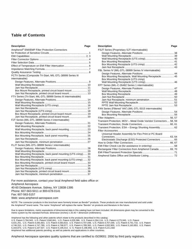
Table of Contents
Description Page
Amphenol® EMI/EMP Filter Protection Connectorsfor Protection of Sensitive Circuits ........................................................ 1EMI Capabilities ................................................................................ 2, 3Filter Connector Options ....................................................................... 4Filter Selection Data .............................................................................. 5Effect of Temperature on EMI Filter Attenuation ................................... 6Impedance Matching Formula............................................................... 7Quality Assurance Testing .................................................................... 8FCTV Series (Composite Tri-Start, MIL-DTL-38999 Series IIIintermateable)
Design Features, Alternate Positions............................................... 9Wall Mounting Receptacle ............................................................. 10Jam Nut Receptacle....................................................................... 11Box Mount Receptacle, printed circuit board mount ...................... 12Jam Nut Receptacle, printed circuit board mount .......................... 13
FTV Series (Tri-Start, MIL-DTL-38999 Series III intermateable)Design Features, Alternate Positions............................................. 14Wall Mounting Receptacle ............................................................. 15Wall Mounting Receptacle (UTS crimp)......................................... 16Jam Nut Receptacle....................................................................... 17Jam Nut Receptacle (UTS crimp) .................................................. 18Box Mount Receptacle, printed circuit board mount ...................... 19Jam Nut Receptacle, printed circuit board mount .......................... 20
FJT Series (MIL-DTL-38999 Series II intermateable)Design Features, Alternate Positions............................................. 21Wall Mounting Receptacle ............................................................. 22Wall Mounting Receptacle, back panel mounting .......................... 23Box Mounting Receptacle .............................................................. 24Box Mounting Receptacle, back panel mounting........................... 25Jam Nut Receptacle....................................................................... 26Jam Nut Receptacle, minimum penetration ................................... 27
FLJT Series (MIL-DTL-38999 Series I intermateable)Design Features, Alternate Positions............................................. 28Wall Mounting Receptacle ............................................................. 29Wall Mounting Receptacle, back panel mounting (UTS crimp)...... 30Box Mounting Receptacle .............................................................. 31Box Mounting Receptacle, back panel mounting (UTS crimp) ...... 32Box Mounting Receptacle, printed circuit board mount ................. 33Jam Nut Receptacle....................................................................... 34Jam Nut Receptacle (UTS crimp) .................................................. 35Jam Nut Receptacle, printed circuit board mount .......................... 36Jam Nut Receptacle, minimum penetration ................................... 37
Description Page
FSJT Series (Proprietary SJT intermateable)Design Features, Alternate Positions ............................................ 38Wall Mounting Receptacle ............................................................. 39Wall Mounting Receptacle (UTS crimp)......................................... 40Box Mounting Receptacle.............................................................. 41Box Mounting Receptacle (UTS crimp) ......................................... 42Jam Nut Receptacle ...................................................................... 43
FBL Series IV (MIL-DTL-38999 Series IV intermateable)Design Features, Alternate Positions ............................................ 44Box Mounting Receptacle, Wall Mounting Receptacle .................. 45Box Mounting Receptacle (UTS crimp)Wall Mounting Receptacle (UTS crimp)......................................... 46
FPT Series (MIL-C-26482 Series 1 intermateable)Design Features, Alternate Positions ............................................ 47Wall Mounting Receptacle ............................................................. 48Box Mounting Receptacle.............................................................. 49Jam Nut Receptacle ...................................................................... 50Jam Nut Receptacle, minimum penetration................................... 51FPTE Wall Mounting Receptacle................................................... 52FPTE Jam Nut Receptacle ............................................................ 53
FAN Series (Filtered “AN”) (MIL-DTL-5015 intermateable)Design Features, Alternate Positions ............................................ 54Box Mounting Receptacle.............................................................. 55
Filter Adapters............................................................................... 56, 57Transient Protection, MOV – Metal Oxide Varistor Connectors.... 58, 59Transient Protection, Diode Connectors ....................................... 60, 61Transient Protection, ESA – Energy Shunting Assembly.................... 62Filter Accessories....................................................................................
Universal Header Assembly for Flex Print or PC BoardConnectors .............................................................................. 63, 64Electrostatic Discharge (ESD) Protected Connectors ................... 65
How to Order Filter Connectors .................................................... 66, 67EMI Filter Check List (for assistance in ordering) ............................... 68Rectangular Filter Connectors from Amphenol Canada ............... 69, 70EMI Filter/Transient Protection Specials ............................................. 71Amphenol Sales Office and Distributor Listing................................... 72
For more assistance, contact your local Amphenol field sales office or:Amphenol Aerospace40-60 Delaware Avenue, Sidney, NY 13838-1395Phone: 607-563-5011 or 800-678-0141Fax: 607-563-5157Web: www.amphenol-aerospace.com
NOTE: The connector products in this brochure were formerly known as Bendix® products. These products are now manufactured and sold under the Amphenol® brand name. The name “Amphenol” will replace the name “Bendix” on products and literature in the future.
Due to space limitations, metric equivalents of dimensional data in this catalog have not been included. All dimensions given may be converted to the metric system by the standard formula: dimension (inches) x 25.40 = dimension (millimeters).
Amphenol has the following and other patents which relate to the products described in this catalog:U.S. Patent 3,764,943, U.S. Patent 3,840,841, U.S. Patent 4,029,386, U.S. Patent 4,264,116, U.S. Patent 4,275,945, U.S. Patent 4,431,251, U.S. Patent 4,440,463, U.S. Patent 4,583,810, U.S. Patent 4,707,048, U.S. Patent 4,707,049, U.S. Patent 4,741,710, U.S. Patent 4,746,310, U.S. Patent 4,747,789, U.S. Patent 4,768,977, U.S. Patent 4,789,360, U.S. Patent 4,932,900, U.S. Patent 5,163,853, U.S. Patent 5,164,873, U.S. Patent 5,167.537, U.S. Patent 5,195,014, U. S. Patent 5,198,958, U.S. Patent 5,211,582Amphenol has additional patents pending, as well as patents and applications in other countries.
Amphenol Aerospace operates quality systems that are certified to ISO9001: 2000 by third party registrars.
1
Amphenol® EMI/EMP Protection Connectors offer the versa-tility of standard connectors with EMI/EMP protection for sensitive circuits. Internal housing of the EMI/EMP devices eliminates costly and bulky exterior discrete protection devices.
Virtually all major MIL-Spec cylindricals can be incorporated with filter devices:
• MIL-DTL-38999 • MIL-DTL-5015• MIL-C-26482 • MIL-C-27599• MIL-C-83723 • MIL-C-26500
Amphenol offers filter connectors that include:• EMP protection using diodes• EMP protection utilizing metal oxide varistors (MOV’s)• Filtered plug connectors• Filtered hermetic connectors• Filter connectors with ESD protection• Combinations of filtering devices within one connector
package
This catalog focuses on the cylindrical connector offerings from Amphenol with EMI/EMP filter transient protection. There are also many rectangular filter connectors that are offered by Amphenol which include:
• MIL-DTL-24308 D-Sub• MIL-DTL-83513 Micro D• ARINC 404/600• DOD-83527 Rack and Panel• MIL-DTL-83733 Rack and Panel
Rectangular filter interconnects are manufactured and sup-plied by Amphenol Canada. See further information at the end of the catalog.Advantages of Filter Connectors:
• Reduction in overall weight and space with the elimina-tion of external filter circuits
• Reduction of solder junctions• Increase in reliability due to fewer connections• Fragile filter elements protected from handling and
environmental damage• Pre-testing from factory and ready for installation
FTVSubminiature Tri-Start, MIL-DTL-38999 Series III, Metal or Composite shells with FilterProtection.
FJTSubminiature JT, MIL-DTL-38999 Series II with FilterProtection.
Filter Contacts Combined with High Speed ContactsFilter Connectors can incorporate high
frequency coax, twinax, triax, quadrax anddifferential twinaxcontacts.
FLJTSubminiature LJT, MIL-DTL-38999 Series I with Filter Protection.
FCTV with Stand-off Flange
Filtered Tri-Startconnectors with composite shells for attachment to printed circuit boards.
MOV ConnectorsMOV’s act as a variable resistor to efficiently dissipate energy.
MOV can be pack-aged singularly or in combinations with other EMI Filtering.
Filter ANConnectorsMIL-DTL-5015 Type Connec-tors with FilterProtection.
FPTMiniature MIL-C-26482 Series 1 with FilterProtection.
Header AssembliesAllow for easy separation and easy termination of connectors when
attaching to flex or printed circuit boards. Allow for electrical testing that would adversely affect sensitive diodes, MOV’s or filter capacitors.
Amphenol EMI/EMP Filter ProtectionConnectorsfor protection of sensitive circuits
®
2
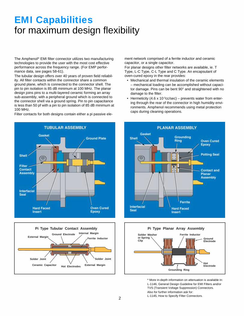
The Amphenol® EMI filter connector utilizes two manufacturing technologies to provide the user with the most cost effective performance across the frequency range. (For EMP perfor-mance data, see pages 58-61).The tubular design offers over 40 years of proven field reliabil-ity. All filter contacts within the connector share a common ground plane, which is connected to the connector shell. The pin to pin isolation is 85 dB minimum at 100 MHz. The planar design joins pins to a multi-layered ceramic forming an array sub-assembly, with a peripheral ground which is connected to the connector shell via a ground spring. Pin to pin capacitance is less than 50 pf with a pin to pin isolation of 85 dB minimum at 100 MHz.Filter contacts for both designs contain either a pi passive ele-
ment network comprised of a ferrite inductor and ceramic capacitor, or a single capacitor.For planar designs other filter networks are available, ie. T Type, L-C Type, C-L Type and C Type. An encapsulant of oven-cured epoxy in the rear provides:
• Mechanical and thermal insulation of the ceramic elements – mechanical loading can be accomplished without capaci-tor damage. Pins can be bent 90° and straightened with no damage to the filter.
• Hermeticity (4.6 x 10⁻³cc/sec) – prevents water from enter-ing through the rear of the connector in high humidity envi-ronments. Amphenol recommends using metal protection caps during cleaning operations.
* More in-depth information on attenuation is available in:L-1146, General Design Guideline for EMI Filters and/orTVS (Transient Voltage Suppression) Connectors.Also for further information ask for:L-1145, How to Specify Filter Connectors.
EMI Capabilitiesfor maximum design flexibility
External MarginGround Electrode Internal Margin
Solder Joint
Ceramic Capacitor Hot Electrodes External Margin
Solder Joint
Ferrite Inductor
Pi Type Tubular Contact Assembly Pi Type Planar Array Assembly
Ferrite Inductor
GroundElectrode
Solder Washeror SpringClip
Grounding Ring
HotElectrode
3
Amphenol provides a wide range of filtering solutions. You can select your options for your particular interference threats - VHF, UHF, HF or other filter ranges, then couple with a connector package of your choice. Or give Amphe-nol your custom shell design requirements for assistance in designing your unique filter solution.
EMI Filter connectors are intended for use in temperatures from –55°C to +125°C. Attenuation will change with feed-through current and temperature.*To assure reliability, connectors may be subjected to an attenuation performance test verifying proper assembly and grounding of the filters. Attenuation data on filter per-formance is stated in reference to a 50 ohm impedance system in order to allow filter performance to be more eas-ily translated into real world impedances.Those interested in determining the expected filter perfor-mance in an impedance system other than 50 ohms may refer to page 7 of this catalog or may contact Amphenol Aerospace for further assistance.
It is suggested that the user analyze his system require-ments for EMI protection in the following areas:
• Working voltage (DC or AC and Frequency)• Peak voltage• Desired attenuation at a given frequency level• Any special capacitance limitations
Definition of Filter Contacts:
Filter contacts can be provided in most frequencies in con-tact sizes 22 or larger. Consult Amphenol Aerospace for availability.Tubular connector designs will meet 3 amps RF current from –55°C through +125°C. Planar connector designs will meet 5 amps.
MF Medium Frequency50 dB performance between 300 - 2999 KHz
HF High Frequency50 dB performance between 3 - 29 MHz
VHF Very High Frequency50 dB performance between 30 - 2999 MHz
UHF Ultra High Frequency50 dB performance between 300 - 2999 MHz
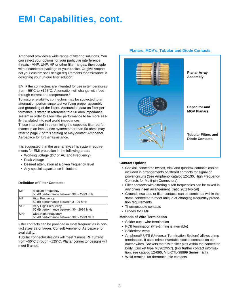
Planars, MOV’s, Tubular and Diode Contacts
Contact Options• Coaxial, concentric twinax, triax and quadrax contacts can be
included in arrangements of filtered contacts for signal or power circuits (See Amphenol catalog 12-130, High Frequency Contacts for Multi-pin Connectors).
• Filter contacts with differing cutoff frequencies can be mixed in any given insert arrangement. (ratio 20:1 typical)
• Ground, insulated or filter contacts can be combined within the same connector to meet unique or changing frequency protec-tion requirements.
• Thermocouple contacts• Diodes for EMP
Methods of Wire Termination• Solder cup - wire termination• PCB termination (Pre-tinning is available)• Solderless wrap• Amphenol® UTS (Universal Termination System) allows crimp
termination. It uses crimp insertable socket contacts on con-ductor wires. Sockets mate with filter pins within the connector body. (Socket type M39029/57). (For further contact informa-tion, see catalog 12-090, MIL-DTL-38999 Series I & II).
• Weld terminal for thermocouple contacts
EMI Capabilities, cont.
Planar Array Assembly
Capacitor and MOV Planars
Tubular Filters andDiode Contacts
4
Filter Connector Options
Other Filter Connector Options include:• Filter adapters eliminate replacement of either existing mated pair. The
adapter provides the circuit protection at the MF, VHF and UHF levels, and is an effective and economical method of introducing EMI/EMP pro-tection to an installed system. Adapters are to be placed between mating faces. (See pages 56, 57).
• Receptacle shell modifications that allow mounting directly to a PC board or flex header. Stand-off shells are available in different configurations. These offer improved reliability by eliminating external spacers and wash-ers. (See pages 12, 13, 19, 20 and 33).
• The hermetic filter connector, while only approximately 1/2 inch longer than standard series connectors, provides all the benefits of a hermetic connector, plus EMI protection for sensitive circuits. The filter assembly is protected by a fused glass insert within a unique steel housing. This design provides the capability to tolerate high level static pressure while maintaining a low level leakage rate. Consult Amphenol Aerospace for more information.
• Composite shell filter connectors meet the MIL-DTL-38999, Series III dimensional length, and offer a light-weight, corrosion resistant, durable connector with the same high performance features as its metal counter-part. The composite filter connector utilizes planar technology to accom-modate VHF-1 or better electrical performance characteristics. (See pages 9-13).
• Filter connectors with ESD (Electrostatic Discharge) protection are avail-able. These MIL-DTL-38999 Series III connectors have an added feature of a Faraday Cage to shunt electrostatic discharge events to the conduc-tive enclosure on which the connector is mounted. (See page 65).
• Filtered Plugs are designed for applications where EMI protection is essential, but access to the receptacle is denied. Designed with the same components as a standard filter receptacle, the filtered plug offers the option of being mounted on the cable harness. It is a cost effective method of achieving EMI protection when length restrictions prohibit inclusion of an adapter to the system. Consult Amphenol Aerospace for availability.
• Diode Connectors offers versatility with transient protection for sensitive circuits, such as TTL lines. Diodes can stand alone or be combined with other filters. (Pages 60, 61).
• Receptacles with EMP protection are available for MIL-DTL-38999 Series IV. (Pages 44-46).
• Amphenol’s Energy Shunting Assembly is a simple, compact unit which provides lightning and electromagnetic pulse pro-tection of systems in which many signal lines enter sensitive electronic equipment. (Page 62).
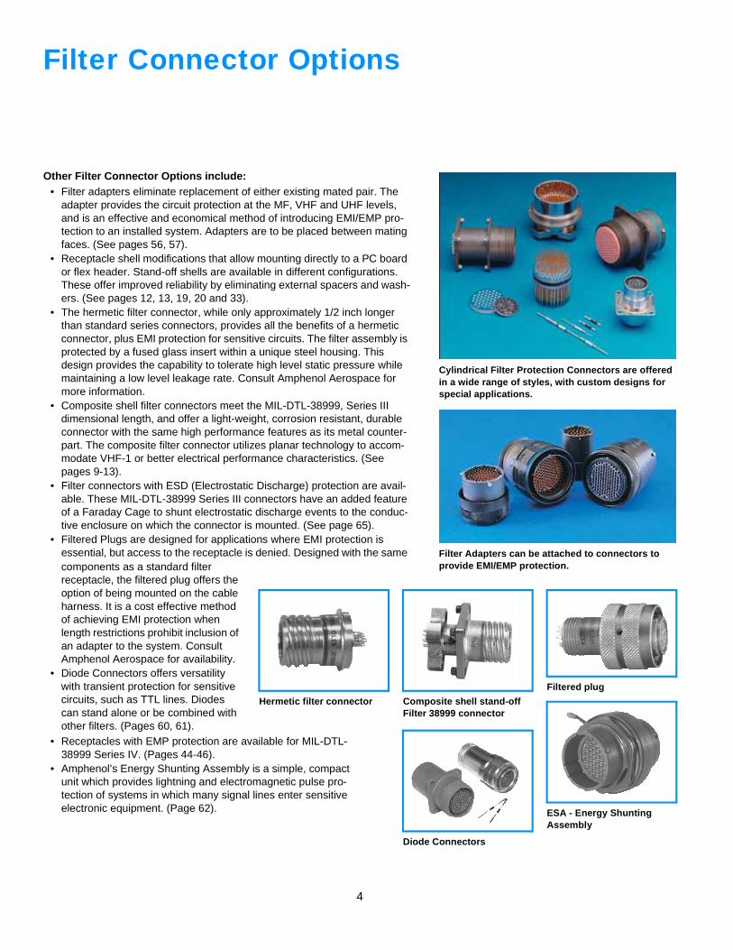
Filter Adapters can be attached to connectors to provide EMI/EMP protection.
Cylindrical Filter Protection Connectors are offered in a wide range of styles, with custom designs for special applications.
Composite shell stand-off Filter 38999 connector
Filtered plug
ESA - Energy Shunting Assembly
Hermetic filter connector
Diode Connectors
5
Filter Selection Data
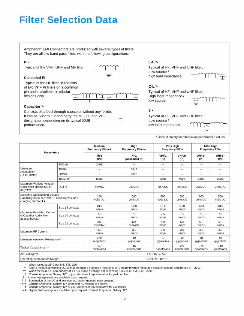
Amphenol® EMI Connectors are produced with several types of filters.They are all low band pass filters with the following configurations:
Pi -Typical of the VHF, UHF and MF filter
Cascaded Pi -Typical of the HF filter. It consistsof two VHF Pi filters on a commonpin and is available in tubulardesigns only.
Capacitor *-Consists of a feed-through capacitor without any ferrite.It can be 50pf to 1µf and carry the MF, HF and VHFdesignation depending on its typical 50dBperformance.
L-C *-Typical of HF, VHF and UHF filter.Low source /high load impedance.
C-L *-Typical of HF, VHF and UHF filter.High load impedance /low source.
T *-Typical of HF, VHF and UHF filter.Low source /low load impedance.
* Consult factory for attenuation performance values.
* When tested at 25°C per MIL-STD-220.** After 2 minutes at working DC voltage through a protective resistance of 1 megohm when measured between contact and ground at +25°C.
*** When measured at a frequency of 1 ±.1kHz and a voltage not exceeding 1.0 V.A.C.R.M.S. at +25°C.† Consult Amphenol, Sidney, NY or your Amphenol representative for part number.
†† Lower leakage rates are available upon request.††† Summation of the DC and low level AC super-imposed peak voltage.
†††† Consult Amphenol, Sidney, NY whenever AC voltage is present.✦ Consult Amphenol, Sidney, NY or your Amphenol representative for availability.
✦✦ Higher DWV ratings are available upon request. Consult Amphenol, Sidney, NY.
Parameters
MediumFrequency Filter✦
HighFrequency Filter✦
Very HighFrequency Filter
Ultra HighFrequency Filter
MF1(Pi)
HF1(Cascaded Pi)
VHF1(Pi)
VHF2†(Pi)
UHF1†(Pi)
UHF2†(Pi)
MinimumAttenuation(Test Points)*
150kHz 20dB – – – – –
15MHz – 50dB – – – –
50MHz – 80dB – – – –
100MHz 80dB – 62dB 46dB 18dB 28dB
Maximum Working Voltage (User must specify DC or AC)††††
DC††† 50VDC 200VDC 200VDC 200VDC 200VDC 200VDC
Dielectric Withstanding VoltageCapability (for 5 sec. with 10 milliamperes max. charging current)✦✦
100volts DC
500volts DC
500volts DC
500volts DC
500volts DC
500volts DC
Maximum Feed-thru Current(DC and/or Audio Fre-quency R.M.S.)
Size 16 contacts13.0amps
13.0amps
13.0amps
13.0amps
13.0amps
13.0amps
Size 20 contacts 7.5amps
7.5amps
7.5amps
7.5amps
7.5amps
7.5amps
Size 22 contacts notavailable
notavailable
5.0amps
5.0amps
5.0amps
5.0amps
Maximum RF Current3.0
amps3.0
amps3.0
amps3.0
amps3.0
amps3.0
amps
Minimum Insulation Resistance** 250megohms
10gigaohms
10gigaohms
10gigaohms
10gigaohms
10gigaohms
Typical Capacitance*** 1.0microfarad
16nanofarads
7nanofarads
2.5nanofarads
375picofarads
710picofarads
Air Leakage†† 4.6 x 10⁻³ cc/sec
Operating Temperature Range –55°C to +125°C
6
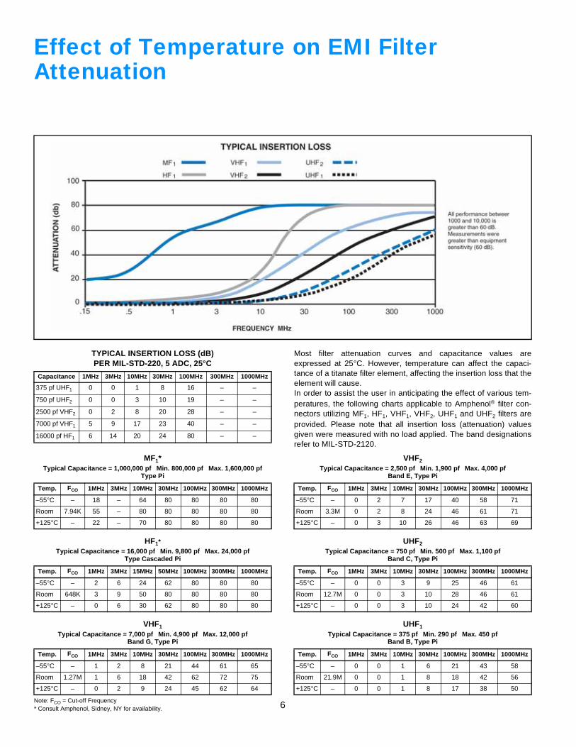
Effect of Temperature on EMI FilterAttenuation
TYPICAL INSERTION LOSS (dB)PER MIL-STD-220, 5 ADC, 25°C
Capacitance 1MHz 3MHz 10MHz 30MHz 100MHz 300MHz 1000MHz
375 pf UHF1 0 0 1 8 16 – –
750 pf UHF2 0 0 3 10 19 – –
2500 pf VHF2 0 2 8 20 28 – –
7000 pf VHF1 5 9 17 23 40 – –
16000 pf HF1 6 14 20 24 80 – –
Note: FCO = Cut-off Frequency* Consult Amphenol, Sidney, NY for availability.
MF1*Typical Capacitance = 1,000,000 pf Min. 800,000 pf Max. 1,600,000 pf
Type Pi
Temp. FCO 1MHz 3MHz 10MHz 30MHz 100MHz 300MHz 1000MHz
–55°C – 18 – 64 80 80 80 80
Room 7.94K 55 – 80 80 80 80 80
+125°C – 22 – 70 80 80 80 80
HF1*Typical Capacitance = 16,000 pf Min. 9,800 pf Max. 24,000 pf
Type Cascaded Pi
Temp. FCO 1MHz 3MHz 15MHz 50MHz 100MHz 300MHz 1000MHz
–55°C – 2 6 24 62 80 80 80
Room 648K 3 9 50 80 80 80 80
+125°C – 0 6 30 62 80 80 80
VHF1
Typical Capacitance = 7,000 pf Min. 4,900 pf Max. 12,000 pfBand G, Type Pi
Temp. FCO 1MHz 3MHz 10MHz 30MHz 100MHz 300MHz 1000MHz
–55°C – 1 2 8 21 44 61 65
Room 1.27M 1 6 18 42 62 72 75
+125°C – 0 2 9 24 45 62 64
Most filter attenuation curves and capacitance values areexpressed at 25°C. However, temperature can affect the capaci-tance of a titanate filter element, affecting the insertion loss that theelement will cause.In order to assist the user in anticipating the effect of various tem-peratures, the following charts applicable to Amphenol® filter con-nectors utilizing MF1, HF1, VHF1, VHF2, UHF1 and UHF2 filters areprovided. Please note that all insertion loss (attenuation) valuesgiven were measured with no load applied. The band designationsrefer to MIL-STD-2120.
VHF2
Typical Capacitance = 2,500 pf Min. 1,900 pf Max. 4,000 pfBand E, Type Pi
Temp. FCO 1MHz 3MHz 10MHz 30MHz 100MHz 300MHz 1000MHz
–55°C – 0 2 7 17 40 58 71
Room 3.3M 0 2 8 24 46 61 71
+125°C – 0 3 10 26 46 63 69
UHF2
Typical Capacitance = 750 pf Min. 500 pf Max. 1,100 pfBand C, Type Pi
Temp. FCO 1MHz 3MHz 10MHz 30MHz 100MHz 300MHz 1000MHz
–55°C – 0 0 3 9 25 46 61
Room 12.7M 0 0 3 10 28 46 61
+125°C – 0 0 3 10 24 42 60
UHF1
Typical Capacitance = 375 pf Min. 290 pf Max. 450 pfBand B, Type Pi
Temp. FCO 1MHz 3MHz 10MHz 30MHz 100MHz 300MHz 1000MHz
–55°C – 0 0 1 6 21 43 58
Room 21.9M 0 0 1 8 18 42 56
+125°C – 0 0 1 8 17 38 50
7
0
20
60
40
80
100
120
140
Att
en
uati
on
- d
B
Attenuation vs Transfer Impedance in 50 Ohm System
Transfer Impedance - Z Ohms
10 1010101010
12
1-0-1-2-3-4
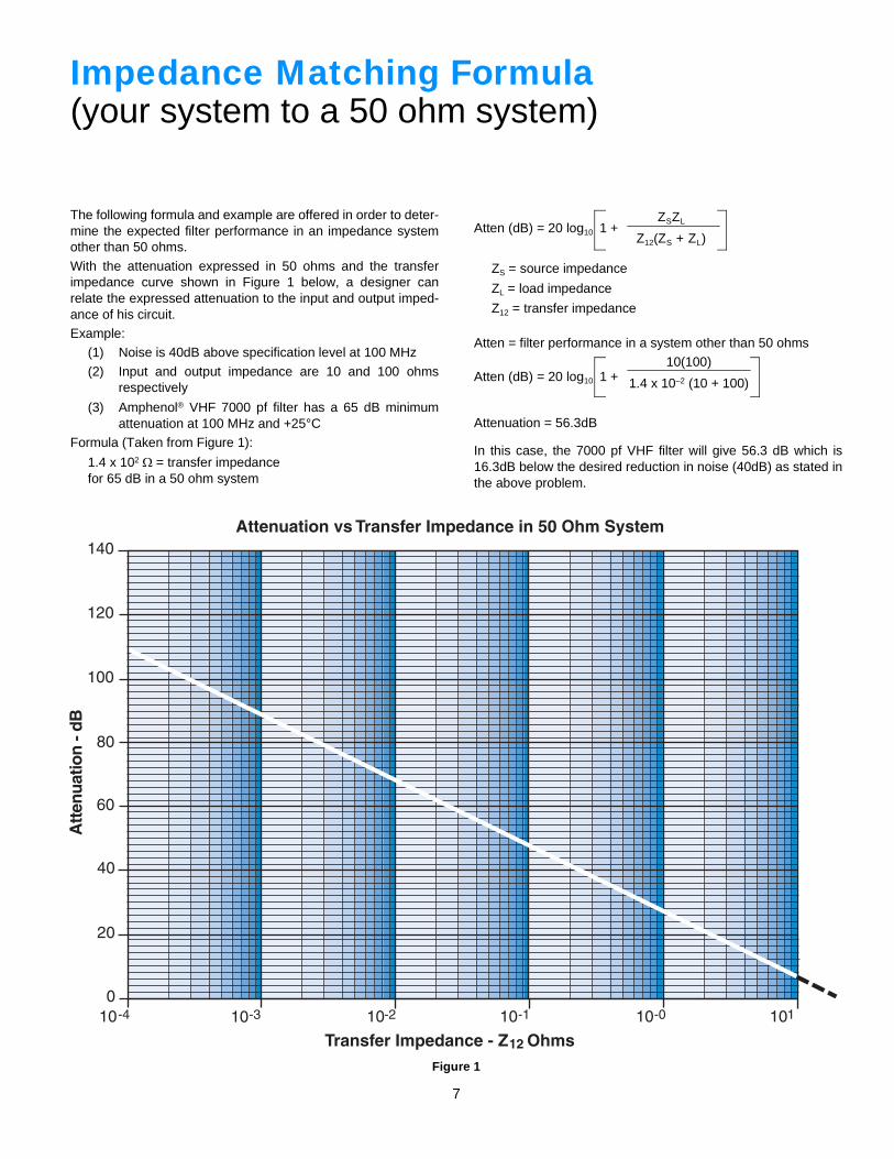
Impedance Matching Formula(your system to a 50 ohm system)
The following formula and example are offered in order to deter-mine the expected filter performance in an impedance systemother than 50 ohms.
With the attenuation expressed in 50 ohms and the transferimpedance curve shown in Figure 1 below, a designer canrelate the expressed attenuation to the input and output imped-ance of his circuit.Example:
(1) Noise is 40dB above specification level at 100 MHz
(2) Input and output impedance are 10 and 100 ohmsrespectively
(3) Amphenol® VHF 7000 pf filter has a 65 dB minimumattenuation at 100 MHz and +25°C
Formula (Taken from Figure 1):
1.4 x 10² Ω = transfer impedancefor 65 dB in a 50 ohm system
Atten (dB) = 20 log10 1 +
ZS = source impedance
ZL = load impedance
Z12 = transfer impedance
Atten = filter performance in a system other than 50 ohms
Atten (dB) = 20 log10 1 +
Attenuation = 56.3dB
In this case, the 7000 pf VHF filter will give 56.3 dB which is16.3dB below the desired reduction in noise (40dB) as stated inthe above problem.
ZSZL
Z12(ZS + ZL)
10(100)
1.4 x 10⁻² (10 + 100)
Figure 1
8
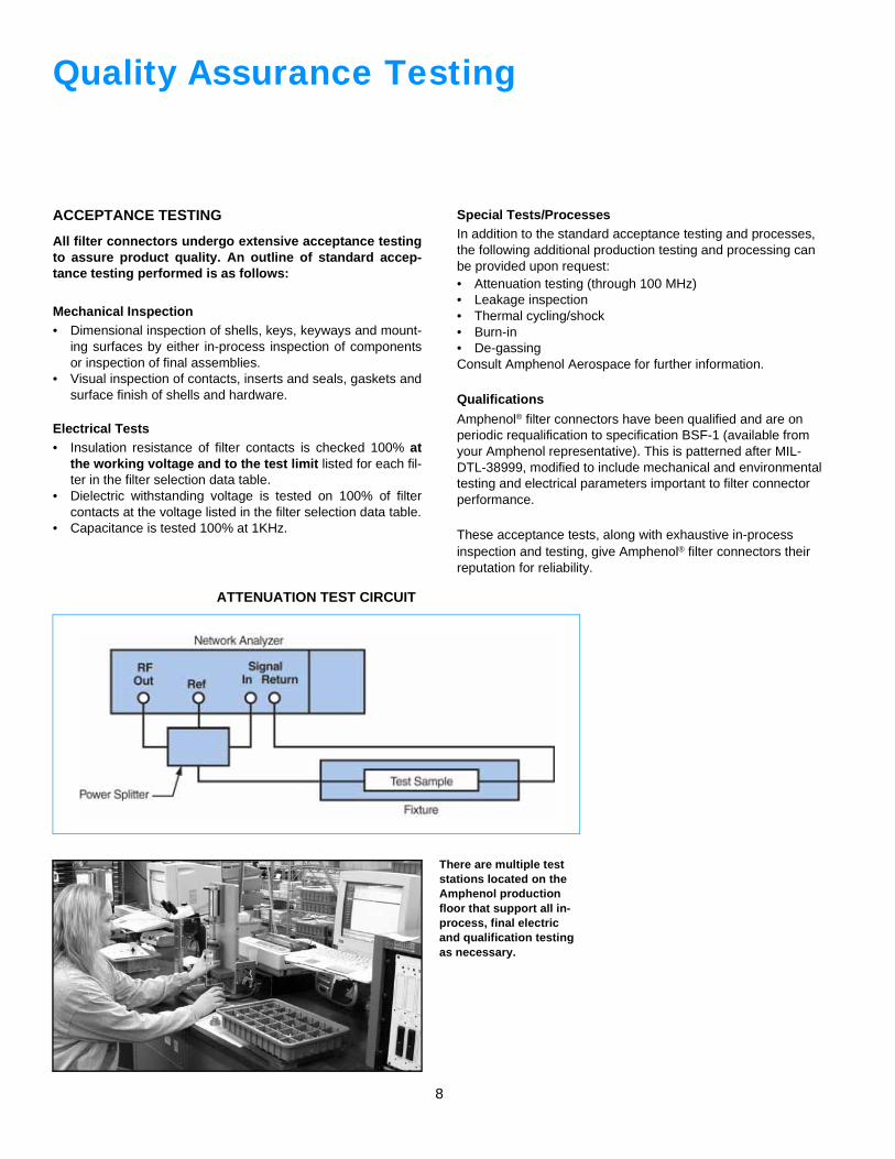
Quality Assurance Testing
ACCEPTANCE TESTING
All filter connectors undergo extensive acceptance testingto assure product quality. An outline of standard accep-tance testing performed is as follows:
Mechanical Inspection• Dimensional inspection of shells, keys, keyways and mount-
ing surfaces by either in-process inspection of componentsor inspection of final assemblies.
• Visual inspection of contacts, inserts and seals, gaskets andsurface finish of shells and hardware.
Electrical Tests• Insulation resistance of filter contacts is checked 100% at
the working voltage and to the test limit listed for each fil-ter in the filter selection data table.
• Dielectric withstanding voltage is tested on 100% of filtercontacts at the voltage listed in the filter selection data table.
• Capacitance is tested 100% at 1KHz.
Special Tests/ProcessesIn addition to the standard acceptance testing and processes, the following additional production testing and processing can be provided upon request:• Attenuation testing (through 100 MHz)• Leakage inspection• Thermal cycling/shock• Burn-in• De-gassingConsult Amphenol Aerospace for further information.
Qualifications
Amphenol® filter connectors have been qualified and are on periodic requalification to specification BSF-1 (available from your Amphenol representative). This is patterned after MIL-DTL-38999, modified to include mechanical and environmental testing and electrical parameters important to filter connector performance.
These acceptance tests, along with exhaustive in-process inspection and testing, give Amphenol® filter connectors their reputation for reliability.
ATTENUATION TEST CIRCUIT
There are multiple test stations located on the Amphenol production floor that support all in-process, final electric and qualification testing as necessary.
9
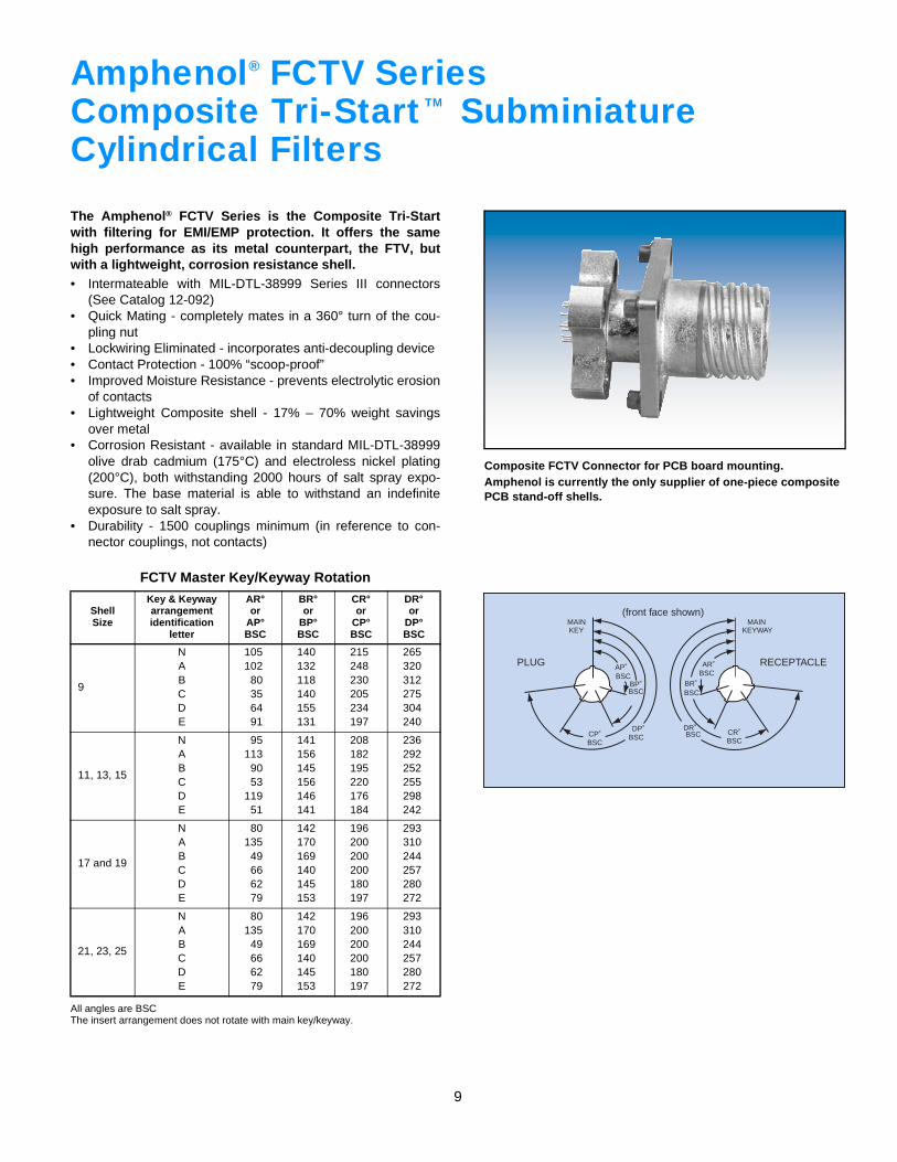
Amphenol FCTV SeriesComposite Tri-Start SubminiatureCylindrical Filters
The Amphenol® FCTV Series is the Composite Tri-Startwith filtering for EMI/EMP protection. It offers the samehigh performance as its metal counterpart, the FTV, butwith a lightweight, corrosion resistance shell.• Intermateable with MIL-DTL-38999 Series III connectors
(See Catalog 12-092)• Quick Mating - completely mates in a 360° turn of the cou-
pling nut• Lockwiring Eliminated - incorporates anti-decoupling device• Contact Protection - 100% “scoop-proof”• Improved Moisture Resistance - prevents electrolytic erosion
of contacts• Lightweight Composite shell - 17% – 70% weight savings
over metal• Corrosion Resistant - available in standard MIL-DTL-38999
olive drab cadmium (175°C) and electroless nickel plating(200°C), both withstanding 2000 hours of salt spray expo-sure. The base material is able to withstand an indefiniteexposure to salt spray.
• Durability - 1500 couplings minimum (in reference to con-nector couplings, not contacts)
All angles are BSCThe insert arrangement does not rotate with main key/keyway.
FCTV Master Key/Keyway Rotation
ShellSize
Key & Keywayarrangement identification
letter
AR°or
AP°BSC
BR°or
BP°BSC
CR°or
CP°BSC
DR°or
DP°BSC
9
NABCDE
105102
80356491
140132118140155131
215248230205234197
265320312275304240
11, 13, 15
NABCDE
95113
9053
11951
141156145156146141
208182195220176184
236292252255298242
17 and 19
NABCDE
80135
49666279
142170169140145153
196200200200180197
293310244257280272
21, 23, 25
NABCDE
80135
49666279
142170169140145153
196200200200180197
293310244257280272
®
TM
AP˚BSC
BP˚BSC
DP˚BSCCP˚
BSC
MAINKEY
PLUG
(front face shown)
AR˚BSC
BR˚BSC
BSCBSC CR˚
DR˚
MAINKEYWAY
RECEPTACLE
Composite FCTV Connector for PCB board mounting.Amphenol is currently the only supplier of one-piece composite PCB stand-off shells.
10
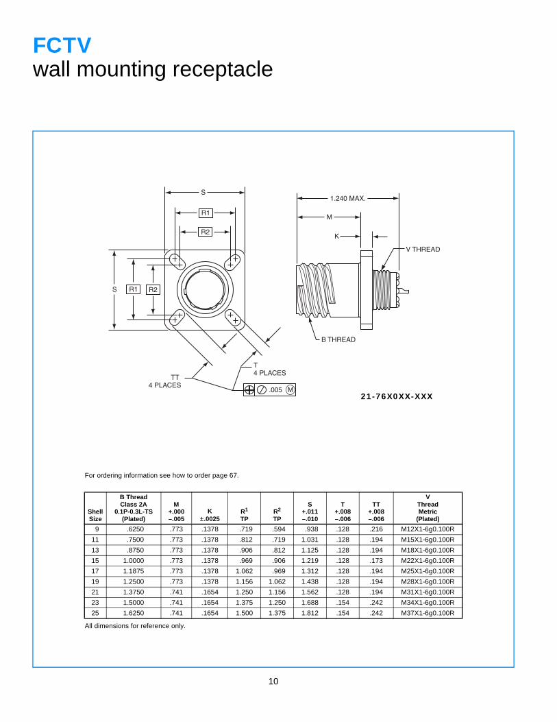
FCTVwall mounting receptacle
For ordering information see how to order page 67.
ShellSize
B ThreadClass 2A
0.1P-0.3L-TS(Plated)
M+.000–.005
K±.0025
R1
TPR2
TP
S+.011–.010
T+.008–.006
TT+.008–.006
VThreadMetric
(Plated)
9 .6250 .773 .1378 .719 .594 .938 .128 .216 M12X1-6g0.100R
11 .7500 .773 .1378 .812 .719 1.031 .128 .194 M15X1-6g0.100R
13 .8750 .773 .1378 .906 .812 1.125 .128 .194 M18X1-6g0.100R
15 1.0000 .773 .1378 .969 .906 1.219 .128 .173 M22X1-6g0.100R
17 1.1875 .773 .1378 1.062 .969 1.312 .128 .194 M25X1-6g0.100R
19 1.2500 .773 .1378 1.156 1.062 1.438 .128 .194 M28X1-6g0.100R
21 1.3750 .741 .1654 1.250 1.156 1.562 .128 .194 M31X1-6g0.100R
23 1.5000 .741 .1654 1.375 1.250 1.688 .154 .242 M34X1-6g0.100R
25 1.6250 .741 .1654 1.500 1.375 1.812 .154 .242 M37X1-6g0.100R
All dimensions for reference only.
S
R1
R2
S R1 R2
B THREAD
V THREAD
K
M
1.240 MAX.
T 4 PLACES
.005 M
TT 4 PLACES
21-76X0XX-XXX
11
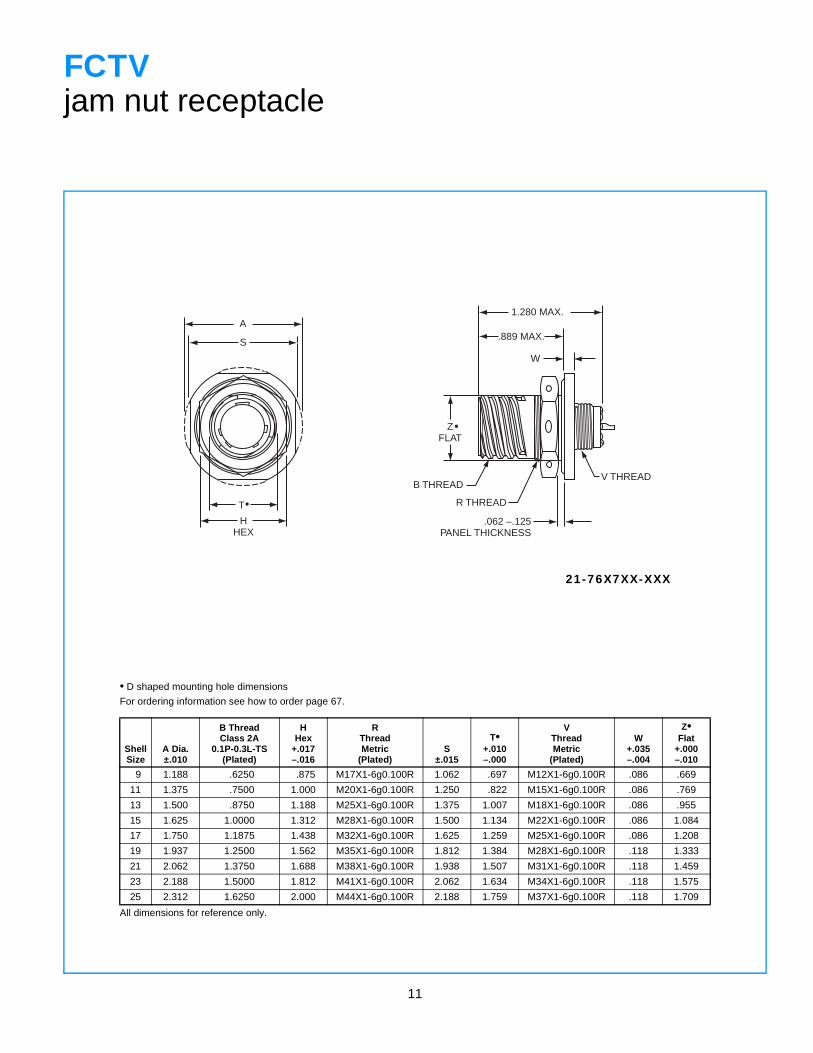
FCTVjam nut receptacle
• D shaped mounting hole dimensions
For ordering information see how to order page 67.
ShellSize
A Dia.±.010
B ThreadClass 2A
0.1P-0.3L-TS(Plated)
HHex
+.017–.016
RThreadMetric
(Plated)S
±.015
T•+.010–.000
VThreadMetric
(Plated)
W+.035–.004
Z•Flat
+.000–.010
9 1.188 .6250 .875 M17X1-6g0.100R 1.062 .697 M12X1-6g0.100R .086 .669
11 1.375 .7500 1.000 M20X1-6g0.100R 1.250 .822 M15X1-6g0.100R .086 .769
13 1.500 .8750 1.188 M25X1-6g0.100R 1.375 1.007 M18X1-6g0.100R .086 .955
15 1.625 1.0000 1.312 M28X1-6g0.100R 1.500 1.134 M22X1-6g0.100R .086 1.084
17 1.750 1.1875 1.438 M32X1-6g0.100R 1.625 1.259 M25X1-6g0.100R .086 1.208
19 1.937 1.2500 1.562 M35X1-6g0.100R 1.812 1.384 M28X1-6g0.100R .118 1.333
21 2.062 1.3750 1.688 M38X1-6g0.100R 1.938 1.507 M31X1-6g0.100R .118 1.459
23 2.188 1.5000 1.812 M41X1-6g0.100R 2.062 1.634 M34X1-6g0.100R .118 1.575
25 2.312 1.6250 2.000 M44X1-6g0.100R 2.188 1.759 M37X1-6g0.100R .118 1.709
All dimensions for reference only.
21-76X7XX-XXX
S
A
T
HHEX
.889 MAX.
ZFLAT
B THREAD
R THREAD
.062 –.125PANEL THICKNESS
W
1.280 MAX.
V THREAD
•
•
12
.005 M
(4) CORROSION RESISTANT STEEL.112-40 UNC-3B INSERTS
A
T
W2 PLACES
B THREAD
M
.673 ±.002
.132 ±.020
SEE NOTE 1
K MAX.PANEL THICKNESS
S2 PLACES
R1
.005 M
(4) CORROSION RESISTANT STEEL.112-40 UNC-3B SELF-LOCKINGCLINCH NUTS PER MIL-N-45938/6-4C
2 PLACES 45˚
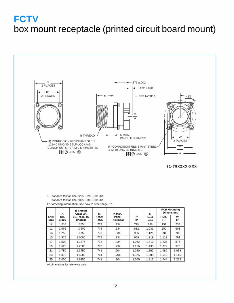
FCTVbox mount receptacle (printed circuit board mount)
1. Standard tail for size 22 is .020 ±.001 dia.Standard tail for size 20 is .030 ±.001 dia.
For ordering information, see how to order page 67.
All dimensions for reference only.
ShellSize
ADia.
±.005
B ThreadClass 2A
0.1P-0.3L-TS(Plated)
M+.000–.005
K Max. Panel
ThicknessR1
TP
S+.011–.010
PCB Mounting Dimensions
T Dia.TP
WTP
9 1.016 .6250 .773 .234 .719 .938 .752 .532
11 1.062 .7500 .773 .234 .812 1.031 .850 .601
13 1.250 .8750 .773 .234 .906 1.125 .994 .703
15 1.375 1.0000 .773 .234 .969 1.219 1.119 .791
17 1.500 1.1875 .773 .234 1.062 1.312 1.237 .875
19 1.625 1.2500 .773 .234 1.156 1.438 1.379 .975
21 1.750 1.3750 .741 .204 1.250 1.562 1.489 1.053
23 1.875 1.5000 .741 .204 1.375 1.688 1.619 1.145
25 2.000 1.6250 .741 .204 1.500 1.812 1.744 1.233
21-78X2XX-XXX
13
S
A
HHEX
.673 ±.002
.132 ±.020
SEE NOTE 1
W
V
M
.889 MAX.
B THREAD
R THREAD .062-.125PANEL THICKNESS
(4) CORROSION RESISTANT STEEL.112-40 UNC-3B INSERTS
.005 M
2 PLACES
T•
ZFLAT
•
45˚
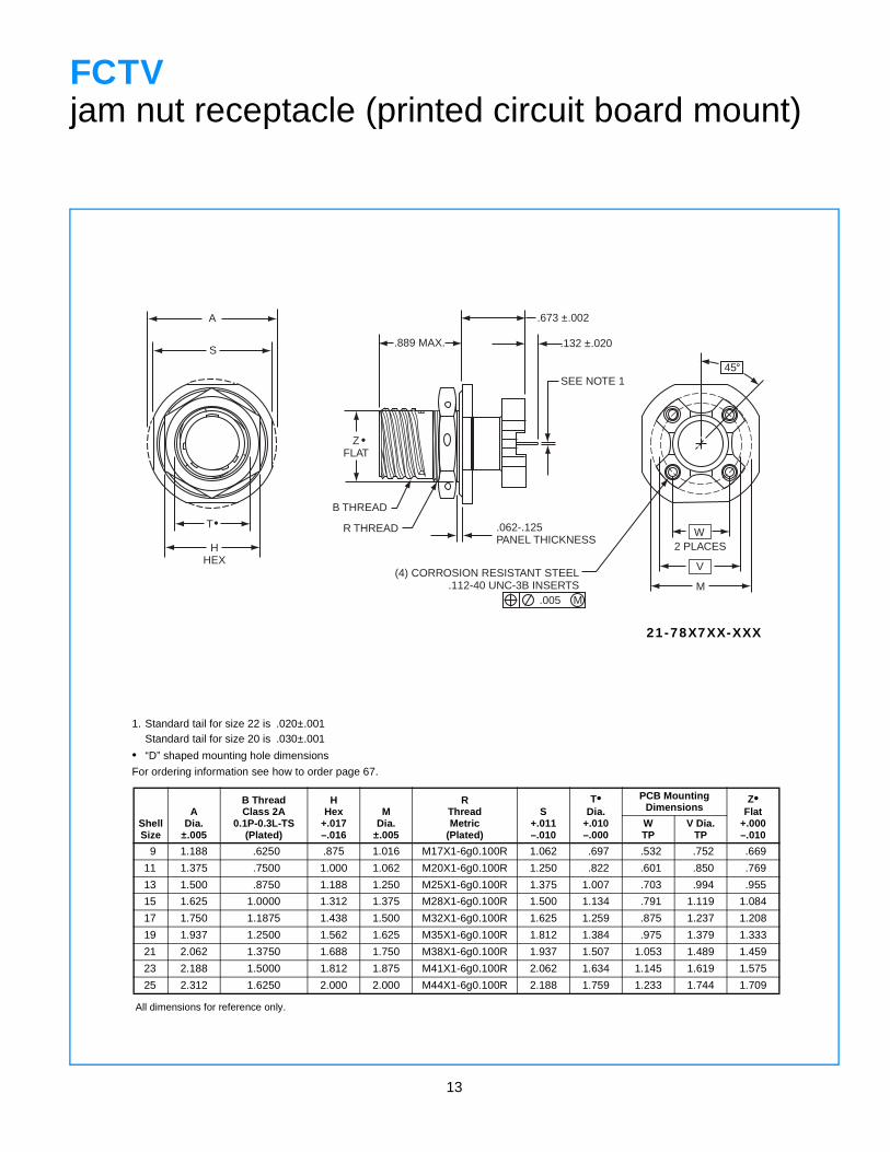
FCTVjam nut receptacle (printed circuit board mount)
1. Standard tail for size 22 is .020±.001Standard tail for size 20 is .030±.001
• “D” shaped mounting hole dimensions
For ordering information see how to order page 67.
ShellSize
ADia.
±.005
B ThreadClass 2A
0.1P-0.3L-TS(Plated)
HHex
+.017–.016
MDia.
±.005
RThreadMetric
(Plated)
S+.011–.010
T•Dia.
+.010–.000
PCB Mounting Dimensions
Z•Flat
+.000–.010
WTP
V Dia.TP
9 1.188 .6250 .875 1.016 M17X1-6g0.100R 1.062 .697 .532 .752 .669
11 1.375 .7500 1.000 1.062 M20X1-6g0.100R 1.250 .822 .601 .850 .769
13 1.500 .8750 1.188 1.250 M25X1-6g0.100R 1.375 1.007 .703 .994 .955
15 1.625 1.0000 1.312 1.375 M28X1-6g0.100R 1.500 1.134 .791 1.119 1.084
17 1.750 1.1875 1.438 1.500 M32X1-6g0.100R 1.625 1.259 .875 1.237 1.208
19 1.937 1.2500 1.562 1.625 M35X1-6g0.100R 1.812 1.384 .975 1.379 1.333
21 2.062 1.3750 1.688 1.750 M38X1-6g0.100R 1.937 1.507 1.053 1.489 1.459
23 2.188 1.5000 1.812 1.875 M41X1-6g0.100R 2.062 1.634 1.145 1.619 1.575
25 2.312 1.6250 2.000 2.000 M44X1-6g0.100R 2.188 1.759 1.233 1.744 1.709
All dimensions for reference only.
21-78X7XX-XXX
14
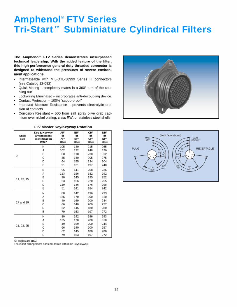
Amphenol FTV SeriesTri-Start Subminiature Cylindrical Filters
The Amphenol® FTV Series demonstrates unsurpassedtechnical leadership. With the added feature of the filter,this high performance general duty threaded connector isdesigned to withstand the pressures of severe environ-ment applications.• Intermateable with MIL-DTL-38999 Series III connectors
(see Catalog 12-092)• Quick Mating – completely mates in a 360° turn of the cou-
pling nut• Lockwiring Eliminated – incorporates anti-decoupling device• Contact Protection – 100% “scoop-proof”• Improved Moisture Resistance – prevents electrolytic ero-
sion of contacts• Corrosion Resistant – 500 hour salt spray olive drab cad-
mium over nickel plating, class RW, or stainless steel shells
All angles are BSCThe insert arrangement does not rotate with main key/keyway.
FTV Master Key/Keyway Rotation
ShellSize
Key & Keywayarrangement identification
letter
AR°or
AP°BSC
BR°or
BP°BSC
CR°or
CP°BSC
DR°or
DP°BSC
9
NABCDE
105102
80356491
140132118140155131
215248230205234197
265320312275304240
11, 13, 15
NABCDE
95113
9053
11951
141156145156146141
208182195220176184
236292252255298242
17 and 19
NABCDE
80135
49666279
142170169140145153
196200200200180197
293310244257280272
21, 23, 25
NABCDE
80135
49666279
142170169140145153
196200200200180197
293310244257280272
®
TM
AP˚BSC
BP˚BSC
DP˚BSCCP˚
BSC
MAINKEY
PLUG
(front face shown)
AR˚BSC
BR˚BSC
BSCBSC CR˚
DR˚
MAINKEYWAY
RECEPTACLE
15
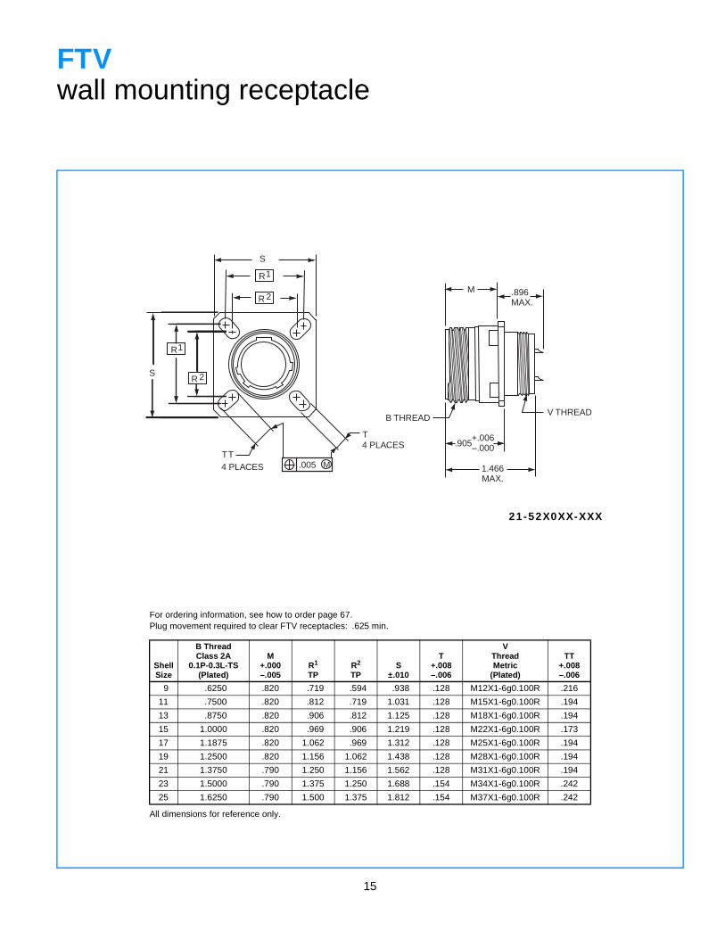
FTVwall mounting receptacle
For ordering information, see how to order page 67.Plug movement required to clear FTV receptacles: .625 min.
ShellSize
B ThreadClass 2A
0.1P-0.3L-TS(Plated)
M+.000–.005
R1
TPR2
TPS
±.010
T+.008–.006
VThreadMetric
(Plated)
TT+.008–.006
9 .6250 .820 .719 .594 .938 .128 M12X1-6g0.100R .216
11 .7500 .820 .812 .719 1.031 .128 M15X1-6g0.100R .194
13 .8750 .820 .906 .812 1.125 .128 M18X1-6g0.100R .194
15 1.0000 .820 .969 .906 1.219 .128 M22X1-6g0.100R .173
17 1.1875 .820 1.062 .969 1.312 .128 M25X1-6g0.100R .194
19 1.2500 .820 1.156 1.062 1.438 .128 M28X1-6g0.100R .194
21 1.3750 .790 1.250 1.156 1.562 .128 M31X1-6g0.100R .194
23 1.5000 .790 1.375 1.250 1.688 .154 M34X1-6g0.100R .242
25 1.6250 .790 1.500 1.375 1.812 .154 M37X1-6g0.100R .242
All dimensions for reference only.
21-52X0XX-XXX
S
R
R
1
2
R1
R 2S
4 PLACESTT
T4 PLACES
.005 M
M .896MAX.
B THREADV THREAD
.905
1.466MAX.
+.006–.000
16
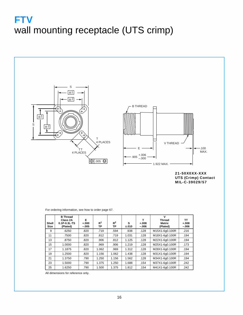
FTVwall mounting receptacle (UTS crimp)
For ordering information, see how to order page 67.
ShellSize
B ThreadClass 2A
0.1P-0.3L-TS(Plated)
E+.000–.005
R1
TPR2
TPS
±.010
T+.008–.006
VThreadMetric
(Plated)
TT+.008–.006
9 .6250 .820 .719 .594 .938 .128 M15X1-6g0.100R .216
11 .7500 .820 .812 .719 1.031 .128 M18X1-6g0.100R .194
13 .8750 .820 .906 .812 1.125 .128 M22X1-6g0.100R .194
15 1.0000 .820 .969 .906 1.219 .128 M25X1-6g0.100R .173
17 1.1875 .820 1.062 .969 1.312 .128 M28X1-6g0.100R .194
19 1.2500 .820 1.156 1.062 1.438 .128 M31X1-6g0.100R .194
21 1.3750 .790 1.250 1.156 1.562 .128 M34X1-6g0.100R .194
23 1.5000 .790 1.375 1.250 1.688 .154 M37X1-6g0.100R .242
25 1.6250 .790 1.500 1.375 1.812 .154 M41X1-6g0.100R .242
All dimensions for reference only.
21-50X0XX-XXXUTS (Crimp) ContactMIL-C-39029/57
S
R
R
1
2
R1
R 2S
4 PLACESTT
T4 PLACES
.005 M
B THREAD
E
+.006–.000.905
V THREAD
1.922 MAX.
.100MAX.
17
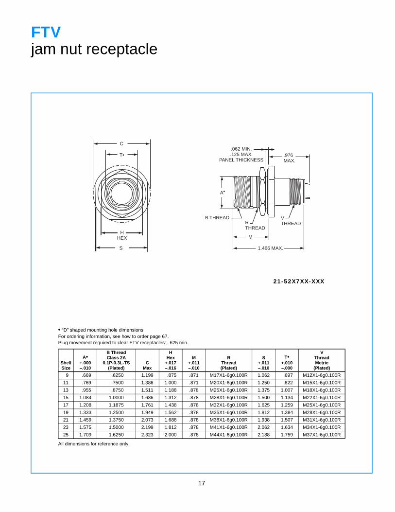
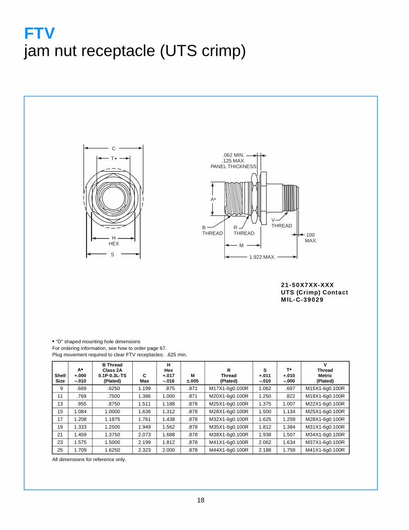
FTVjam nut receptacle
• “D” shaped mounting hole dimensionsFor ordering information, see how to order page 67.Plug movement required to clear FTV receptacles: .625 min.
ShellSize
A•+.000–.010
B ThreadClass 2A
0.1P-0.3L-TS(Plated)
CMax
HHex
+.017–.016
M+.011–.010
RThread(Plated)
S+.011–.010
T•+.010–.000
VThreadMetric
(Plated)
9 .669 .6250 1.199 .875 .871 M17X1-6g0.100R 1.062 .697 M12X1-6g0.100R
11 .769 .7500 1.386 1.000 .871 M20X1-6g0.100R 1.250 .822 M15X1-6g0.100R
13 .955 .8750 1.511 1.188 .878 M25X1-6g0.100R 1.375 1.007 M18X1-6g0.100R
15 1.084 1.0000 1.636 1.312 .878 M28X1-6g0.100R 1.500 1.134 M22X1-6g0.100R
17 1.208 1.1875 1.761 1.438 .878 M32X1-6g0.100R 1.625 1.259 M25X1-6g0.100R
19 1.333 1.2500 1.949 1.562 .878 M35X1-6g0.100R 1.812 1.384 M28X1-6g0.100R
21 1.459 1.3750 2.073 1.688 .878 M38X1-6g0.100R 1.938 1.507 M31X1-6g0.100R
23 1.575 1.5000 2.199 1.812 .878 M41X1-6g0.100R 2.062 1.634 M34X1-6g0.100R
25 1.709 1.6250 2.323 2.000 .878 M44X1-6g0.100R 2.188 1.759 M37X1-6g0.100R
All dimensions for reference only.
21-52X7XX-XXX
C
T•
HHEX
S
A•
.062 MIN..125 MAX.
PANEL THICKNESS
B THREADRTHREAD
M
VTHREAD
.976MAX.
1.466 MAX.
18
FTVjam nut receptacle (UTS crimp)
• “D” shaped mounting hole dimensionsFor ordering information, see how to order page 67.Plug movement required to clear FTV receptacles: .625 min.
ShellSize
A•+.000–.010
B ThreadClass 2A
0.1P-0.3L-TS(Plated)
CMax
HHex
+.017–.016
M±.005
RThread(Plated)
S+.011–.010
T•+.010–.000
VThreadMetric
(Plated)
9 .669 .6250 1.199 .875 .871 M17X1-6g0.100R 1.062 .697 M15X1-6g0.100R
11 .769 .7500 1.386 1.000 .871 M20X1-6g0.100R 1.250 .822 M18X1-6g0.100R
13 .955 .8750 1.511 1.188 .878 M25X1-6g0.100R 1.375 1.007 M22X1-6g0.100R
15 1.084 1.0000 1.636 1.312 .878 M28X1-6g0.100R 1.500 1.134 M25X1-6g0.100R
17 1.208 1.1875 1.761 1.438 .878 M32X1-6g0.100R 1.625 1.259 M28X1-6g0.100R
19 1.333 1.2500 1.949 1.562 .878 M35X1-6g0.100R 1.812 1.384 M31X1-6g0.100R
21 1.459 1.3750 2.073 1.688 .878 M38X1-6g0.100R 1.938 1.507 M34X1-6g0.100R
23 1.575 1.5000 2.199 1.812 .878 M41X1-6g0.100R 2.062 1.634 M37X1-6g0.100R
25 1.709 1.6250 2.323 2.000 .878 M44X1-6g0.100R 2.188 1.759 M41X1-6g0.100R
All dimensions for reference only.
21-50X7XX-XXXUTS (Crimp) ContactMIL-C-39029
C
HHEX
S
T•
A
.062 MIN..125 MAX.
PANEL THICKNESS
BTHREAD
RTHREAD
M
1.922 MAX.
VTHREAD
.100MAX.
•
19
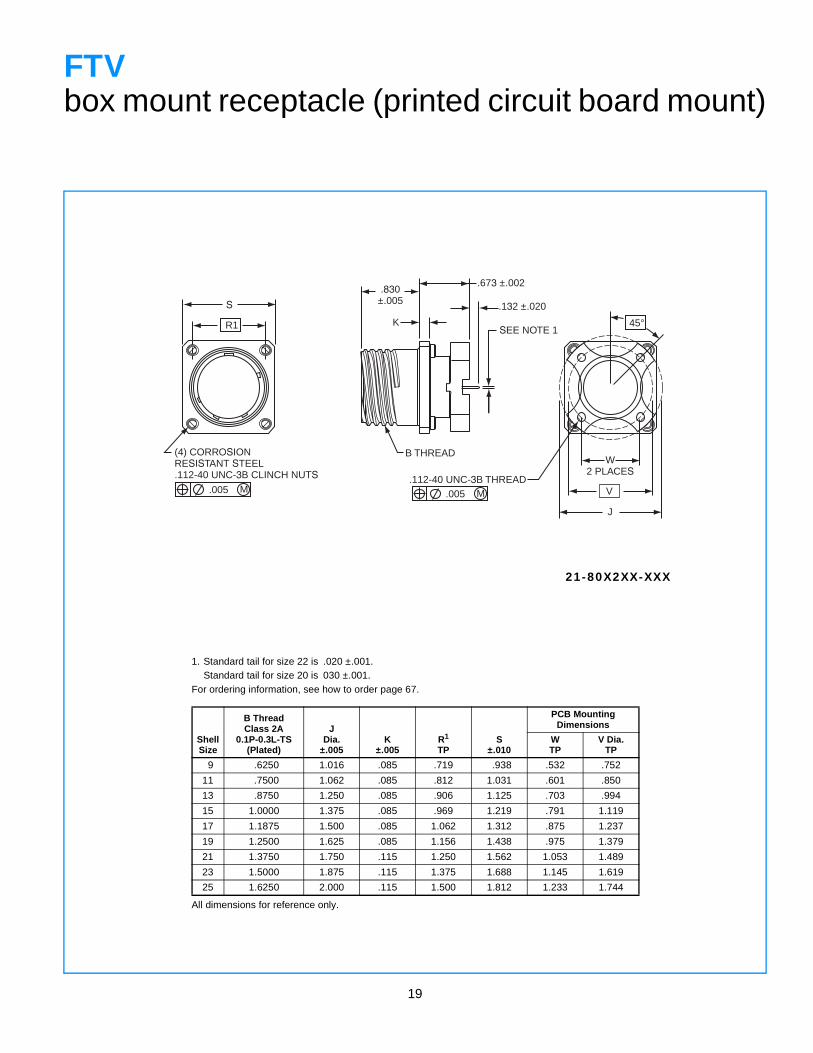
FTVbox mount receptacle (printed circuit board mount)
1. Standard tail for size 22 is .020 ±.001.Standard tail for size 20 is 030 ±.001.
For ordering information, see how to order page 67.
ShellSize
B ThreadClass 2A
0.1P-0.3L-TS(Plated)
JDia.
±.005K
±.005R1
TPS
±.010
PCB Mounting Dimensions
WTP
V Dia.TP
9 .6250 1.016 .085 .719 .938 .532 .752
11 .7500 1.062 .085 .812 1.031 .601 .850
13 .8750 1.250 .085 .906 1.125 .703 .994
15 1.0000 1.375 .085 .969 1.219 .791 1.119
17 1.1875 1.500 .085 1.062 1.312 .875 1.237
19 1.2500 1.625 .085 1.156 1.438 .975 1.379
21 1.3750 1.750 .115 1.250 1.562 1.053 1.489
23 1.5000 1.875 .115 1.375 1.688 1.145 1.619
25 1.6250 2.000 .115 1.500 1.812 1.233 1.744
All dimensions for reference only.
21-80X2XX-XXX
R1
S
(4) CORROSIONRESISTANT STEEL.112-40 UNC-3B CLINCH NUTS
.005 M
B THREAD
K
.005 M.112-40 UNC-3B THREAD
45°
V
W2 PLACES
J
.673 ±.002
.132 ±.020
.830±.005
SEE NOTE 1
20
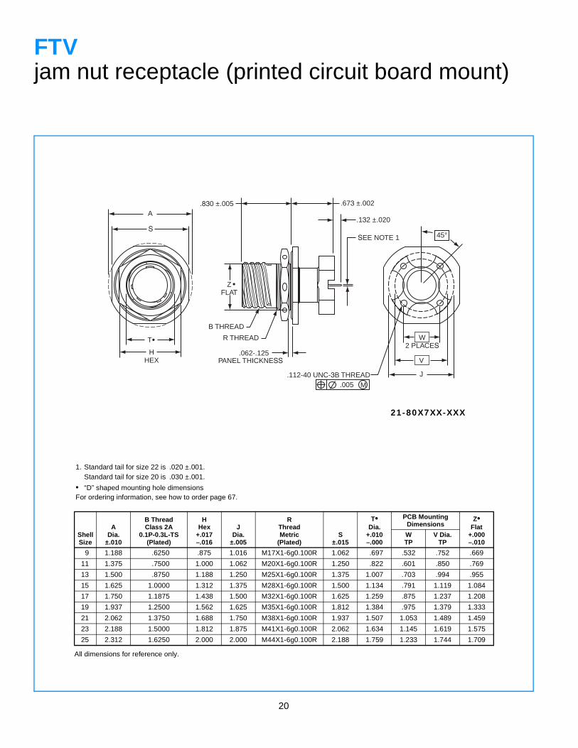
FTVjam nut receptacle (printed circuit board mount)
1. Standard tail for size 22 is .020 ±.001.Standard tail for size 20 is .030 ±.001.
• “D” shaped mounting hole dimensionsFor ordering information, see how to order page 67.
ShellSize
ADia.
±.010
B ThreadClass 2A
0.1P-0.3L-TS(Plated)
HHex
+.017–.016
JDia.
±.005
RThreadMetric
(Plated)S
±.015
T•Dia.
+.010–.000
PCB Mounting Dimensions
Z•Flat
+.000–.010
WTP
V Dia.TP
9 1.188 .6250 .875 1.016 M17X1-6g0.100R 1.062 .697 .532 .752 .669
11 1.375 .7500 1.000 1.062 M20X1-6g0.100R 1.250 .822 .601 .850 .769
13 1.500 .8750 1.188 1.250 M25X1-6g0.100R 1.375 1.007 .703 .994 .955
15 1.625 1.0000 1.312 1.375 M28X1-6g0.100R 1.500 1.134 .791 1.119 1.084
17 1.750 1.1875 1.438 1.500 M32X1-6g0.100R 1.625 1.259 .875 1.237 1.208
19 1.937 1.2500 1.562 1.625 M35X1-6g0.100R 1.812 1.384 .975 1.379 1.333
21 2.062 1.3750 1.688 1.750 M38X1-6g0.100R 1.937 1.507 1.053 1.489 1.459
23 2.188 1.5000 1.812 1.875 M41X1-6g0.100R 2.062 1.634 1.145 1.619 1.575
25 2.312 1.6250 2.000 2.000 M44X1-6g0.100R 2.188 1.759 1.233 1.744 1.709
All dimensions for reference only.
21-80X7XX-XXX
S
A
HHEX
.673 ±.002
.132 ±.020
SEE NOTE 1 45°
W2 PLACES
V
J
.830 ±.005
B THREAD
R THREAD
.062-.125PANEL THICKNESS
.112-40 UNC-3B THREAD.005 M
T•
ZFLAT
•
21
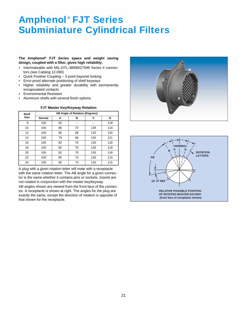
Amphenol FJT SeriesSubminiature Cylindrical Filters
The Amphenol® FJT Series space and weight savingdesign, coupled with a filter, gives high reliability.• Intermateable with MIL-DTL-38999/27599 Series II connec-
tors (see Catalog 12-090)• Quick Positive Coupling – 3 point bayonet locking• Error-proof alternate positioning of shell keyways• Higher reliability and greater durability with permanently
encapsulated contacts• Environmental Resistant• Aluminum shells with several finish options
A plug with a given rotation letter will mate with a receptacle with the same rotation letter. The AB angle for a given connec-tor is the same whether it contains pins or sockets. Inserts are not rotated in conjunction with the master key/keyway.AB angles shown are viewed from the front face of the connec-tor. A receptacle is shown at right. The angles for the plug are exactly the same, except the direction of rotation is opposite of that shown for the receptacle.
FJT Master Key/Keyway Rotation
ShellSize
AB Angle of Rotation (Degrees)
Normal A B C D
8 100 82 – – 118
10 100 86 72 128 114
12 100 80 68 132 120
14 100 79 66 134 121
16 100 82 70 130 118
18 100 82 70 130 118
20 100 82 70 130 118
22 100 85 74 126 115
24 100 85 74 126 115
®
ROTATIONLETTERS
NORMAL
B A D C
AB
10 JT REF
RELATIVE POSSIBLE POSITIONOF ROTATED MASTER KEYWAY (front face of receptacle shown)
˚
22
S
R
RS
.005 M
T4 HOLES
V THREAD.322 +.000–.005
+.006–.000
1.066MAX.
.380
.322 +.000–.005
+.006–.000.380
N
ZMAX.
P*
ZMAX.
N
P*
V THREAD
1.542MAX.
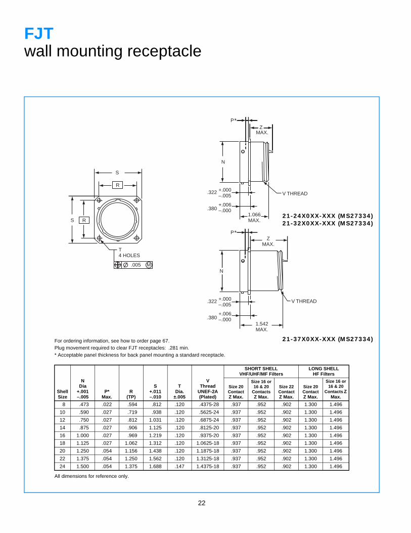
FJTwall mounting receptacle
For ordering information, see how to order page 67.Plug movement required to clear FJT receptacles: .281 min.* Acceptable panel thickness for back panel mounting a standard receptacle.
ShellSize
NDia
+.001–.005
P*Max.
R(TP)
S+.011–.010
TDia.
±.005
VThread
UNEF-2A(Plated)
SHORT SHELLVHF/UHF/MF Filters
LONG SHELLHF Filters
Size 20ContactZ Max.
Size 16 or 16 & 20
ContactsZ Max.
Size 22ContactZ Max.
Size 20ContactZ Max.
Size 16 or 16 & 20
Contacts Z Max.
8 .473 .022 .594 .812 .120 .4375-28 .937 .952 .902 1.300 1.496
10 .590 .027 .719 .938 .120 .5625-24 .937 .952 .902 1.300 1.496
12 .750 .027 .812 1.031 .120 .6875-24 .937 .952 .902 1.300 1.496
14 .875 .027 .906 1.125 .120 .8125-20 .937 .952 .902 1.300 1.496
16 1.000 .027 .969 1.219 .120 .9375-20 .937 .952 .902 1.300 1.496
18 1.125 .027 1.062 1.312 .120 1.0625-18 .937 .952 .902 1.300 1.496
20 1.250 .054 1.156 1.438 .120 1.1875-18 .937 .952 .902 1.300 1.496
22 1.375 .054 1.250 1.562 .120 1.3125-18 .937 .952 .902 1.300 1.496
24 1.500 .054 1.375 1.688 .147 1.4375-18 .937 .952 .902 1.300 1.496
All dimensions for reference only.
21-24X0XX-XXX (MS27334)21-32X0XX-XXX (MS27334)
21-37X0XX-XXX (MS27334)
23
S R
R
S
.005 M
T4 HOLES
P
ZMAX.
.447+.000–.005
NW
.322+.000–.005
.505 +.006–.000
1.066MAX.
V THREAD
P
ZMAX.
.447+.000–.005
.322+.000–.005
.505 +.006–.000
1.542MAX.
W N
V THREAD
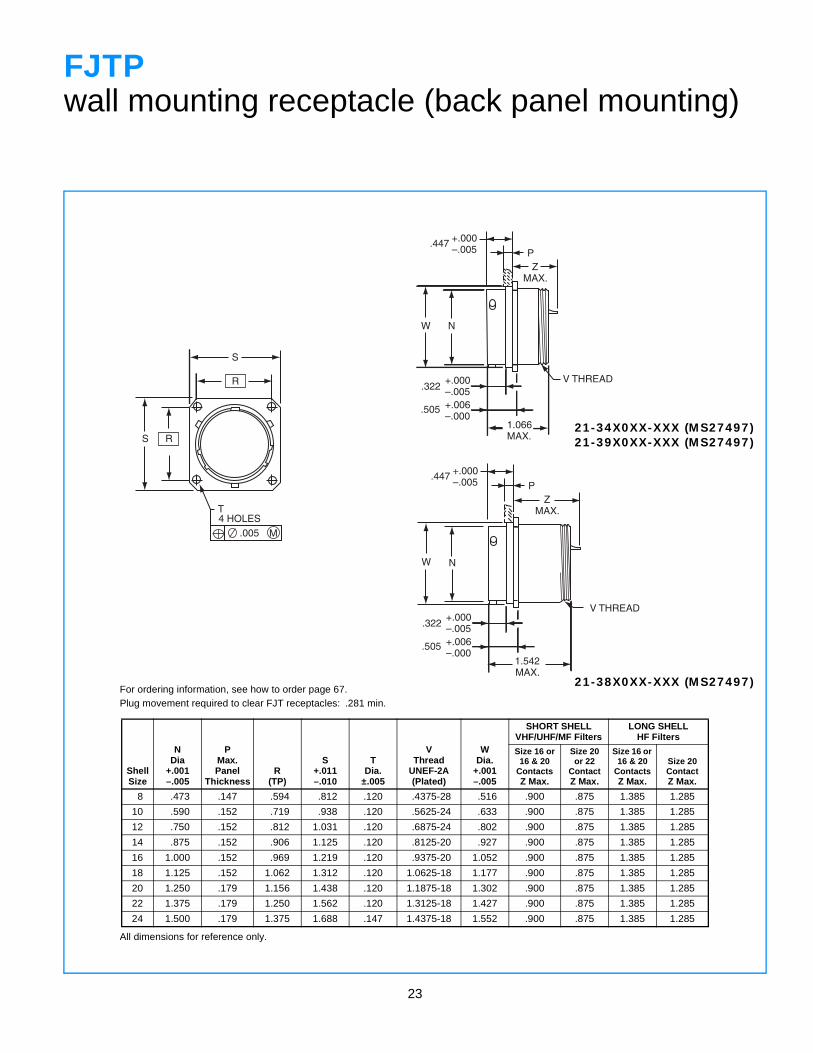
FJTPwall mounting receptacle (back panel mounting)
For ordering information, see how to order page 67.Plug movement required to clear FJT receptacles: .281 min.
ShellSize
NDia
+.001–.005
PMax.Panel
ThicknessR
(TP)
S+.011–.010
TDia.
±.005
VThread
UNEF-2A(Plated)
WDia.
+.001–.005
SHORT SHELLVHF/UHF/MF Filters
LONG SHELLHF Filters
Size 16 or 16 & 20
ContactsZ Max.
Size 20or 22
ContactZ Max.
Size 16 or 16 & 20
ContactsZ Max.
Size 20ContactZ Max.
8 .473 .147 .594 .812 .120 .4375-28 .516 .900 .875 1.385 1.285
10 .590 .152 .719 .938 .120 .5625-24 .633 .900 .875 1.385 1.285
12 .750 .152 .812 1.031 .120 .6875-24 .802 .900 .875 1.385 1.285
14 .875 .152 .906 1.125 .120 .8125-20 .927 .900 .875 1.385 1.285
16 1.000 .152 .969 1.219 .120 .9375-20 1.052 .900 .875 1.385 1.285
18 1.125 .152 1.062 1.312 .120 1.0625-18 1.177 .900 .875 1.385 1.285
20 1.250 .179 1.156 1.438 .120 1.1875-18 1.302 .900 .875 1.385 1.285
22 1.375 .179 1.250 1.562 .120 1.3125-18 1.427 .900 .875 1.385 1.285
24 1.500 .179 1.375 1.688 .147 1.4375-18 1.552 .900 .875 1.385 1.285
All dimensions for reference only.
21-34X0XX-XXX (MS27497)21-39X0XX-XXX (MS27497)
21-38X0XX-XXX (MS27497)
24
S R
R
S
.005 M
THOLES
N
+.000–.005
.322
.380+.006–.000
1.542MAX.
ZMAX.
ZMAX.
K
+.000–.005
.322
.380+.006–.000
1.066MAX.
N K
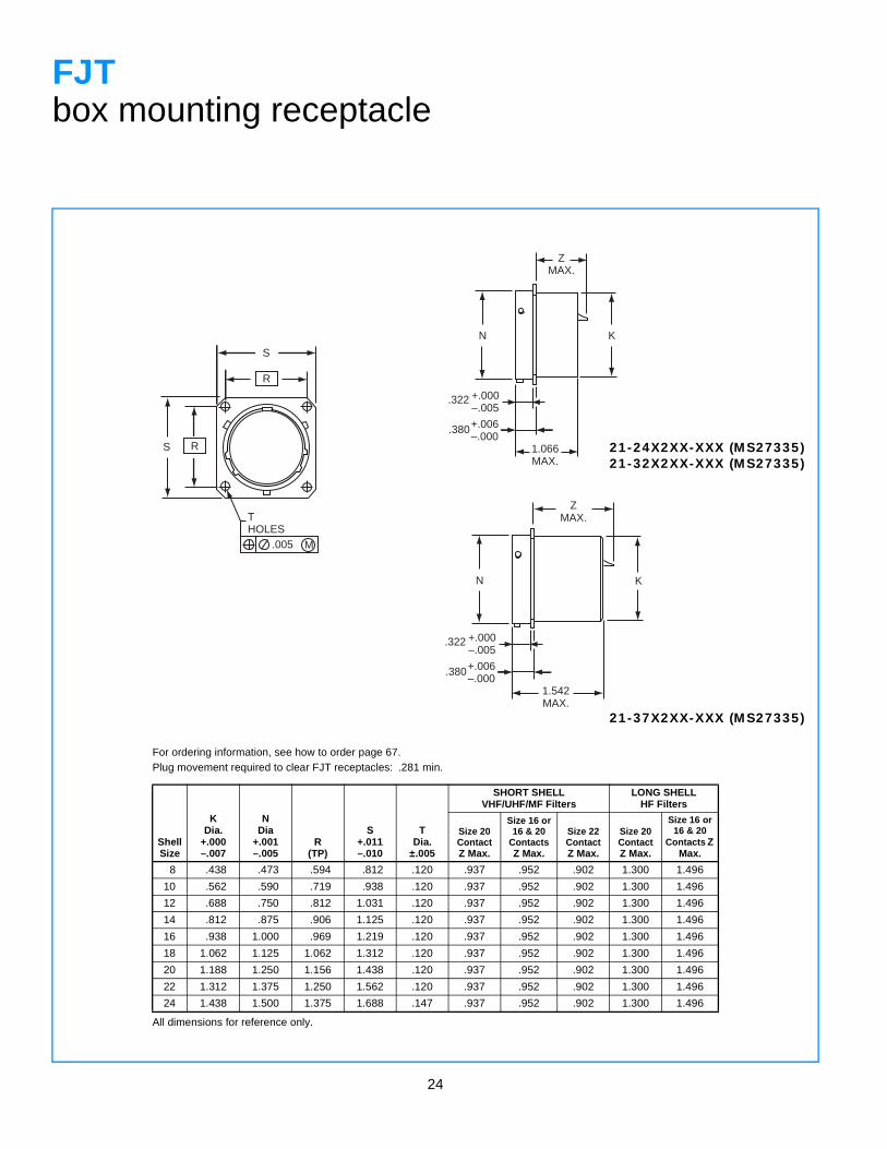
FJTbox mounting receptacle
For ordering information, see how to order page 67.Plug movement required to clear FJT receptacles: .281 min.
ShellSize
KDia.
+.000–.007
NDia
+.001–.005
R(TP)
S+.011–.010
TDia.
±.005
SHORT SHELLVHF/UHF/MF Filters
LONG SHELLHF Filters
Size 20ContactZ Max.
Size 16 or 16 & 20
ContactsZ Max.
Size 22ContactZ Max.
Size 20ContactZ Max.
Size 16 or 16 & 20
Contacts Z Max.
8 .438 .473 .594 .812 .120 .937 .952 .902 1.300 1.496
10 .562 .590 .719 .938 .120 .937 .952 .902 1.300 1.496
12 .688 .750 .812 1.031 .120 .937 .952 .902 1.300 1.496
14 .812 .875 .906 1.125 .120 .937 .952 .902 1.300 1.496
16 .938 1.000 .969 1.219 .120 .937 .952 .902 1.300 1.496
18 1.062 1.125 1.062 1.312 .120 .937 .952 .902 1.300 1.496
20 1.188 1.250 1.156 1.438 .120 .937 .952 .902 1.300 1.496
22 1.312 1.375 1.250 1.562 .120 .937 .952 .902 1.300 1.496
24 1.438 1.500 1.375 1.688 .147 .937 .952 .902 1.300 1.496
All dimensions for reference only.
21-24X2XX-XXX (MS27335)21-32X2XX-XXX (MS27335)
21-37X2XX-XXX (MS27335)
25
N
1.066MAX.
ZMAX.
KW
.447+.000–.005
+.000–.005.322
+.006–.000
.505
P
ZMAX.
.447+.000–.005
P
1.542MAX.
+.000–.005.322
+.006–.000
.505
N KW
S R
R
S
.005 M
T4 HOLES
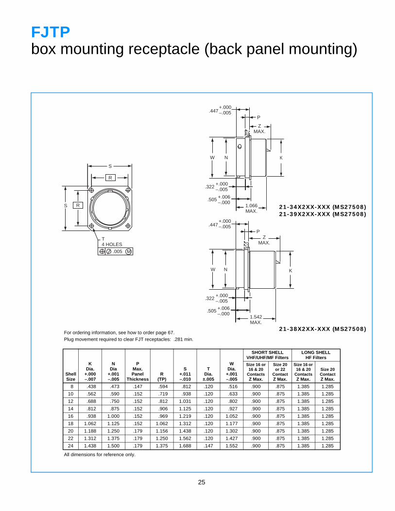
FJTPbox mounting receptacle (back panel mounting)
For ordering information, see how to order page 67.Plug movement required to clear FJT receptacles: .281 min.
ShellSize
KDia.
+.000–.007
NDia
+.001–.005
PMax.Panel
ThicknessR
(TP)
S+.011–.010
TDia.
±.005
WDia.
+.001–.005
SHORT SHELLVHF/UHF/MF Filters
LONG SHELLHF Filters
Size 16 or 16 & 20
ContactsZ Max.
Size 20or 22
ContactZ Max.
Size 16 or 16 & 20
ContactsZ Max.
Size 20ContactZ Max.
8 .438 .473 .147 .594 .812 .120 .516 .900 .875 1.385 1.285
10 .562 .590 .152 .719 .938 .120 .633 .900 .875 1.385 1.285
12 .688 .750 .152 .812 1.031 .120 .802 .900 .875 1.385 1.285
14 .812 .875 .152 .906 1.125 .120 .927 .900 .875 1.385 1.285
16 .938 1.000 .152 .969 1.219 .120 1.052 .900 .875 1.385 1.285
18 1.062 1.125 .152 1.062 1.312 .120 1.177 .900 .875 1.385 1.285
20 1.188 1.250 .179 1.156 1.438 .120 1.302 .900 .875 1.385 1.285
22 1.312 1.375 .179 1.250 1.562 .120 1.427 .900 .875 1.385 1.285
24 1.438 1.500 .179 1.375 1.688 .147 1.552 .900 .875 1.385 1.285
All dimensions for reference only.
21-34X2XX-XXX (MS27508)21-39X2XX-XXX (MS27508)
21-38X2XX-XXX (MS27508)
26
S2 PLACES
HHEX
C
A •
•T
3 LOCKWIRE HOLES .059 DIA. MIN.
PANEL THICKNESS.062-.109
V THREAD
3 LOCKWIRE HOLES .059 DIA. MIN.
PANEL THICKNESS.062-.109
N
RTHREAD
MZ
1.066MAX.
RTHREAD
M1.632MAX.
N
V THREAD
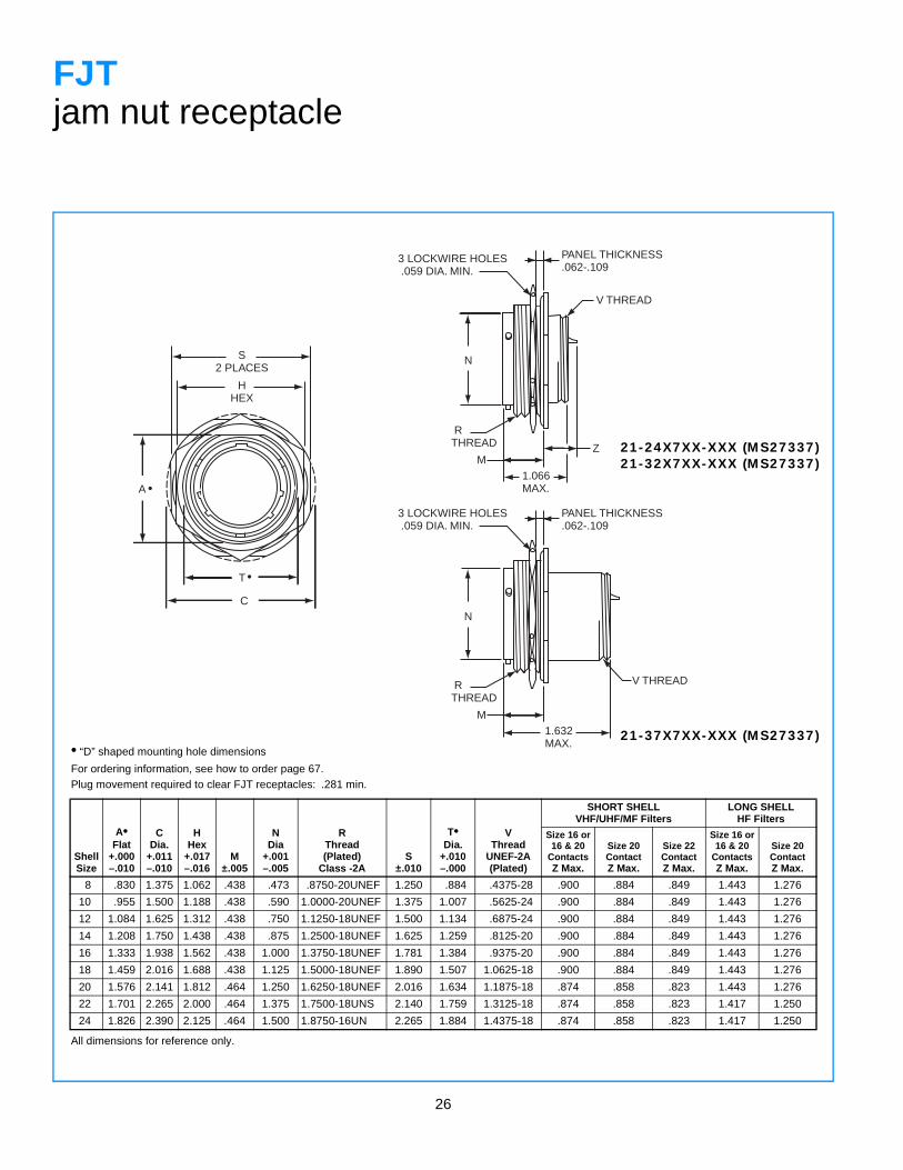
FJTjam nut receptacle
• “D” shaped mounting hole dimensions
For ordering information, see how to order page 67.Plug movement required to clear FJT receptacles: .281 min.
ShellSize
A•Flat
+.000–.010
CDia.
+.011–.010
HHex
+.017–.016
M±.005
NDia
+.001–.005
RThread(Plated)
Class -2AS
±.010
T•Dia.
+.010–.000
VThread
UNEF-2A(Plated)
SHORT SHELLVHF/UHF/MF Filters
LONG SHELLHF Filters
Size 16 or16 & 20
ContactsZ Max.
Size 20ContactZ Max.
Size 22ContactZ Max.
Size 16 or16 & 20
ContactsZ Max.
Size 20ContactZ Max.
8 .830 1.375 1.062 .438 .473 .8750-20UNEF 1.250 .884 .4375-28 .900 .884 .849 1.443 1.276
10 .955 1.500 1.188 .438 .590 1.0000-20UNEF 1.375 1.007 .5625-24 .900 .884 .849 1.443 1.276
12 1.084 1.625 1.312 .438 .750 1.1250-18UNEF 1.500 1.134 .6875-24 .900 .884 .849 1.443 1.276
14 1.208 1.750 1.438 .438 .875 1.2500-18UNEF 1.625 1.259 .8125-20 .900 .884 .849 1.443 1.276
16 1.333 1.938 1.562 .438 1.000 1.3750-18UNEF 1.781 1.384 .9375-20 .900 .884 .849 1.443 1.276
18 1.459 2.016 1.688 .438 1.125 1.5000-18UNEF 1.890 1.507 1.0625-18 .900 .884 .849 1.443 1.276
20 1.576 2.141 1.812 .464 1.250 1.6250-18UNEF 2.016 1.634 1.1875-18 .874 .858 .823 1.443 1.276
22 1.701 2.265 2.000 .464 1.375 1.7500-18UNS 2.140 1.759 1.3125-18 .874 .858 .823 1.417 1.250
24 1.826 2.390 2.125 .464 1.500 1.8750-16UN 2.265 1.884 1.4375-18 .874 .858 .823 1.417 1.250
All dimensions for reference only.
21-24X7XX-XXX (MS27337)21-32X7XX-XXX (MS27337)
21-37X7XX-XXX (MS27337)
27
S2 PLACES
HHEX
C
A•
T •
N
3 LOCKWIRE HOLES.044 DIA. MIN.
1.361MAX.
PANEL THICKNESS.062 -.603
RTHREAD
M
Z MIN.
RTHREAD
M1
3 LOCKWIRE HOLES.044 DIA. MIN.
1.735MAX.
PANEL THICKNESS.062 -1.000
N
Z MIN.
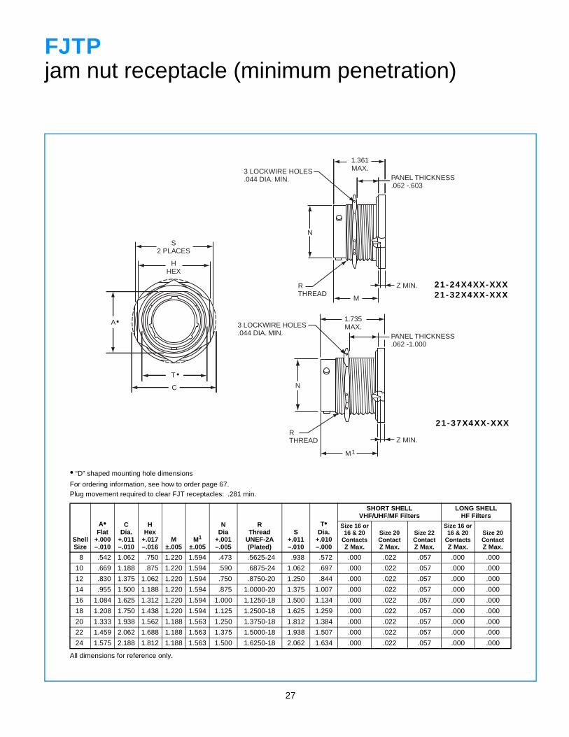
FJTPjam nut receptacle (minimum penetration)
• “D” shaped mounting hole dimensions
For ordering information, see how to order page 67.Plug movement required to clear FJT receptacles: .281 min.
ShellSize
A•Flat
+.000–.010
CDia.
+.011–.010
HHex
+.017–.016
M±.005
M1
±.005
NDia
+.001–.005
RThread
UNEF-2A (Plated)
S+.011–.010
T•Dia.
+.010–.000
SHORT SHELLVHF/UHF/MF Filters
LONG SHELLHF Filters
Size 16 or16 & 20
ContactsZ Max.
Size 20ContactZ Max.
Size 22ContactZ Max.
Size 16 or16 & 20
ContactsZ Max.
Size 20ContactZ Max.
8 .542 1.062 .750 1.220 1.594 .473 .5625-24 .938 .572 .000 .022 .057 .000 .000
10 .669 1.188 .875 1.220 1.594 .590 .6875-24 1.062 .697 .000 .022 .057 .000 .000
12 .830 1.375 1.062 1.220 1.594 .750 .8750-20 1.250 .844 .000 .022 .057 .000 .000
14 .955 1.500 1.188 1.220 1.594 .875 1.0000-20 1.375 1.007 .000 .022 .057 .000 .000
16 1.084 1.625 1.312 1.220 1.594 1.000 1.1250-18 1.500 1.134 .000 .022 .057 .000 .000
18 1.208 1.750 1.438 1.220 1.594 1.125 1.2500-18 1.625 1.259 .000 .022 .057 .000 .000
20 1.333 1.938 1.562 1.188 1.563 1.250 1.3750-18 1.812 1.384 .000 .022 .057 .000 .000
22 1.459 2.062 1.688 1.188 1.563 1.375 1.5000-18 1.938 1.507 .000 .022 .057 .000 .000
24 1.575 2.188 1.812 1.188 1.563 1.500 1.6250-18 2.062 1.634 .000 .022 .057 .000 .000
All dimensions for reference only.
21-24X4XX-XXX21-32X4XX-XXX
21-37X4XX-XXX
28
RELATIVE POSSIBLE POSITIONOF ROTATED MASTER KEYWAY (front face of receptacle shown)
ROTATIONLETTERS
NORMAL
B A D C
AB
5 LJT REF˚
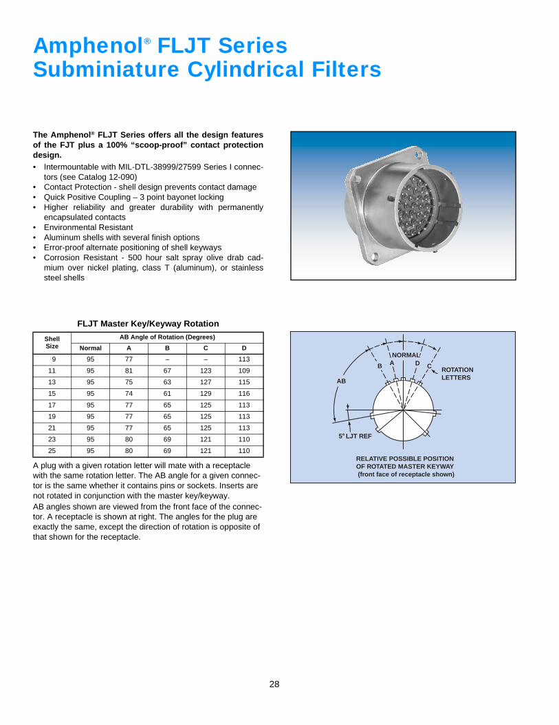
Amphenol FLJT SeriesSubminiature Cylindrical Filters
The Amphenol® FLJT Series offers all the design featuresof the FJT plus a 100% “scoop-proof” contact protectiondesign.• Intermountable with MIL-DTL-38999/27599 Series I connec-
tors (see Catalog 12-090)• Contact Protection - shell design prevents contact damage• Quick Positive Coupling – 3 point bayonet locking• Higher reliability and greater durability with permanently
encapsulated contacts• Environmental Resistant• Aluminum shells with several finish options• Error-proof alternate positioning of shell keyways• Corrosion Resistant - 500 hour salt spray olive drab cad-
mium over nickel plating, class T (aluminum), or stainlesssteel shells
A plug with a given rotation letter will mate with a receptacle with the same rotation letter. The AB angle for a given connec-tor is the same whether it contains pins or sockets. Inserts are not rotated in conjunction with the master key/keyway.AB angles shown are viewed from the front face of the connec-tor. A receptacle is shown at right. The angles for the plug are exactly the same, except the direction of rotation is opposite of that shown for the receptacle.
FLJT Master Key/Keyway Rotation
ShellSize
AB Angle of Rotation (Degrees)
Normal A B C D
9 95 77 – – 113
11 95 81 67 123 109
13 95 75 63 127 115
15 95 74 61 129 116
17 95 77 65 125 113
19 95 77 65 125 113
21 95 77 65 125 113
23 95 80 69 121 110
25 95 80 69 121 110
®
29
S
R
S R
T4 HOLES
.005 M
N
ZMAX.
V THREADM
1.403MAX.
+.005–.000
.717
ZMAX.
N
V THREADM
1.403MAX.
+.005–.000
.717
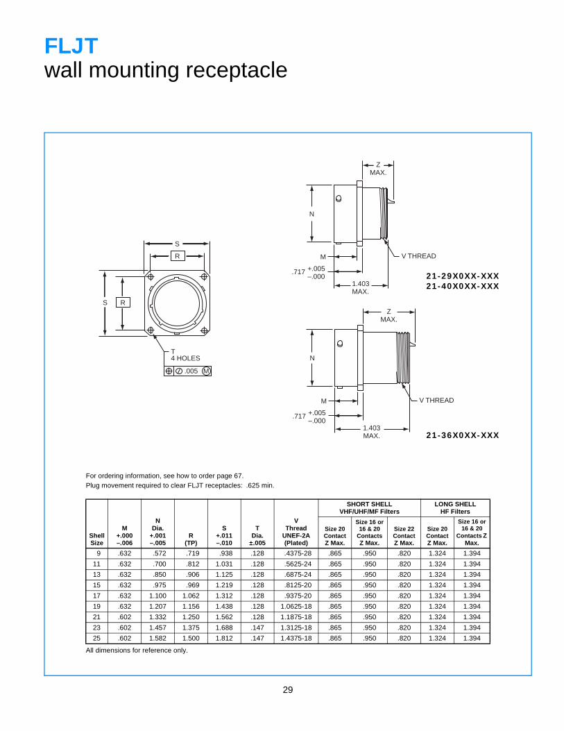
FLJTwall mounting receptacle
For ordering information, see how to order page 67.Plug movement required to clear FLJT receptacles: .625 min.
ShellSize
M+.000–.006
NDia.
+.001–.005
R(TP)
S+.011–.010
TDia.
±.005
VThread
UNEF-2A(Plated)
SHORT SHELLVHF/UHF/MF Filters
LONG SHELLHF Filters
Size 20ContactZ Max.
Size 16 or 16 & 20
ContactsZ Max.
Size 22ContactZ Max.
Size 20ContactZ Max.
Size 16 or 16 & 20
Contacts Z Max.
9 .632 .572 .719 .938 .128 .4375-28 .865 .950 .820 1.324 1.394
11 .632 .700 .812 1.031 .128 .5625-24 .865 .950 .820 1.324 1.394
13 .632 .850 .906 1.125 .128 .6875-24 .865 .950 .820 1.324 1.394
15 .632 .975 .969 1.219 .128 .8125-20 .865 .950 .820 1.324 1.394
17 .632 1.100 1.062 1.312 .128 .9375-20 .865 .950 .820 1.324 1.394
19 .632 1.207 1.156 1.438 .128 1.0625-18 .865 .950 .820 1.324 1.394
21 .602 1.332 1.250 1.562 .128 1.1875-18 .865 .950 .820 1.324 1.394
23 .602 1.457 1.375 1.688 .147 1.3125-18 .865 .950 .820 1.324 1.394
25 .602 1.582 1.500 1.812 .147 1.4375-18 .865 .950 .820 1.324 1.394
All dimensions for reference only.
21-29X0XX-XXX21-40X0XX-XXX
21-36X0XX-XXX
30
S
R
S R
T4 HOLES
.005 M
ZMAX.
V THREADM
1.403MAX.
+.005–.000
.905
N
P *
P *
D
V THREAD1+.005–.000
.921
+.006–.000
1.021
1.921 MAX.
N
.100MAX.
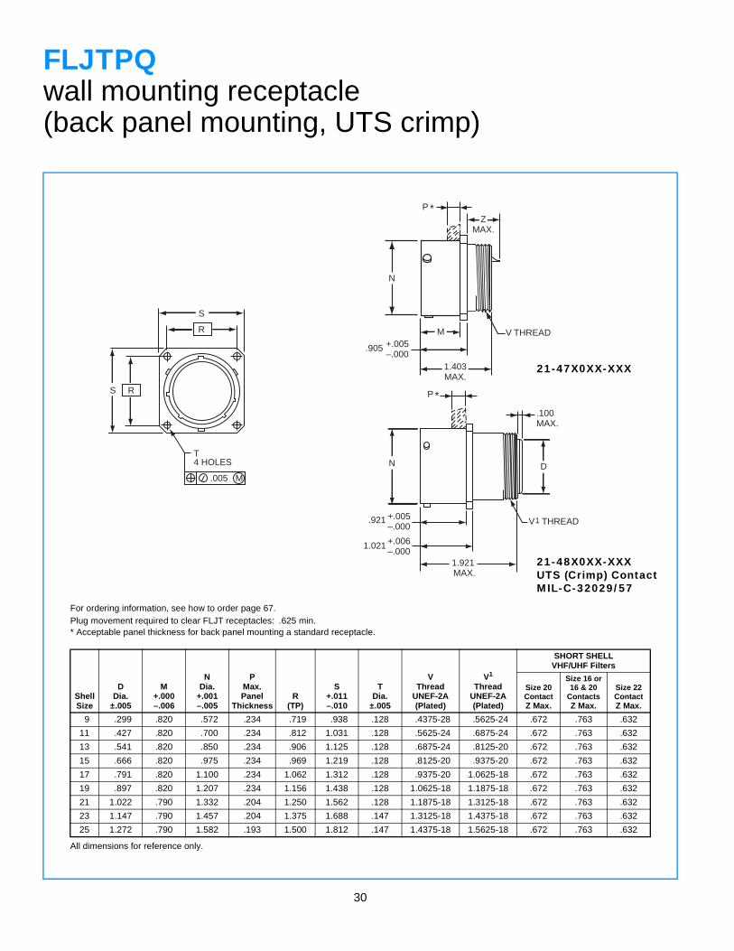
FLJTPQwall mounting receptacle(back panel mounting, UTS crimp)
For ordering information, see how to order page 67.Plug movement required to clear FLJT receptacles: .625 min.* Acceptable panel thickness for back panel mounting a standard receptacle.
ShellSize
DDia.
±.005
M+.000–.006
NDia.
+.001–.005
PMax.Panel
ThicknessR
(TP)
S+.011–.010
TDia.
±.005
VThread
UNEF-2A(Plated)
V1
ThreadUNEF-2A(Plated)
SHORT SHELLVHF/UHF Filters
Size 20ContactZ Max.
Size 16 or 16 & 20
ContactsZ Max.
Size 22ContactZ Max.
9 .299 .820 .572 .234 .719 .938 .128 .4375-28 .5625-24 .672 .763 .632
11 .427 .820 .700 .234 .812 1.031 .128 .5625-24 .6875-24 .672 .763 .632
13 .541 .820 .850 .234 .906 1.125 .128 .6875-24 .8125-20 .672 .763 .632
15 .666 .820 .975 .234 .969 1.219 .128 .8125-20 .9375-20 .672 .763 .632
17 .791 .820 1.100 .234 1.062 1.312 .128 .9375-20 1.0625-18 .672 .763 .632
19 .897 .820 1.207 .234 1.156 1.438 .128 1.0625-18 1.1875-18 .672 .763 .632
21 1.022 .790 1.332 .204 1.250 1.562 .128 1.1875-18 1.3125-18 .672 .763 .632
23 1.147 .790 1.457 .204 1.375 1.688 .147 1.3125-18 1.4375-18 .672 .763 .632
25 1.272 .790 1.582 .193 1.500 1.812 .147 1.4375-18 1.5625-18 .672 .763 .632
All dimensions for reference only.
21-47X0XX-XXX
21-48X0XX-XXXUTS (Crimp) ContactMIL-C-32029/57
31
S
R
S R
T4 HOLES
.005 M
N
ZMAX.
K
1.403MAX.
+.005–.000
.717
M
N
ZMAX.
K
1.931MAX.
+.005–.000
.717
M
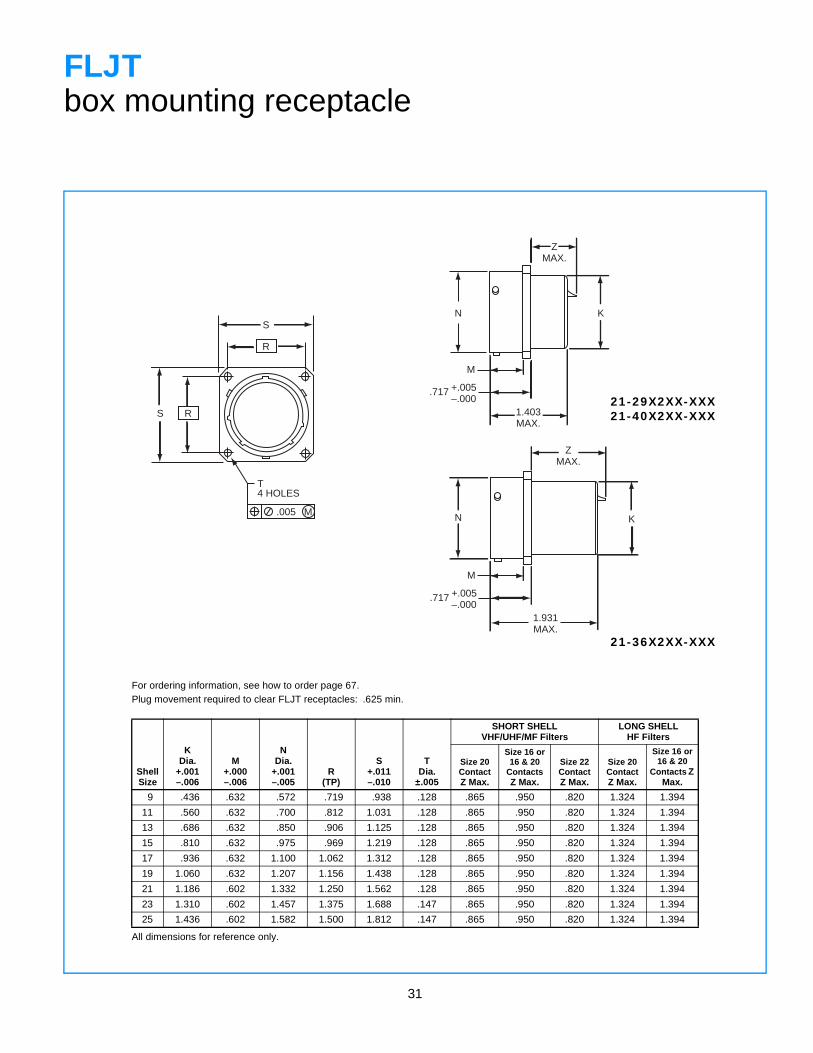
FLJTbox mounting receptacle
For ordering information, see how to order page 67.Plug movement required to clear FLJT receptacles: .625 min.
ShellSize
KDia.
+.001–.006
M+.000–.006
NDia.
+.001–.005
R(TP)
S+.011–.010
TDia.
±.005
SHORT SHELLVHF/UHF/MF Filters
LONG SHELLHF Filters
Size 20ContactZ Max.
Size 16 or 16 & 20
ContactsZ Max.
Size 22ContactZ Max.
Size 20ContactZ Max.
Size 16 or 16 & 20
Contacts Z Max.
9 .436 .632 .572 .719 .938 .128 .865 .950 .820 1.324 1.394
11 .560 .632 .700 .812 1.031 .128 .865 .950 .820 1.324 1.394
13 .686 .632 .850 .906 1.125 .128 .865 .950 .820 1.324 1.394
15 .810 .632 .975 .969 1.219 .128 .865 .950 .820 1.324 1.394
17 .936 .632 1.100 1.062 1.312 .128 .865 .950 .820 1.324 1.394
19 1.060 .632 1.207 1.156 1.438 .128 .865 .950 .820 1.324 1.394
21 1.186 .602 1.332 1.250 1.562 .128 .865 .950 .820 1.324 1.394
23 1.310 .602 1.457 1.375 1.688 .147 .865 .950 .820 1.324 1.394
25 1.436 .602 1.582 1.500 1.812 .147 .865 .950 .820 1.324 1.394
All dimensions for reference only.
21-29X2XX-XXX21-40X2XX-XXX
21-36X2XX-XXX
32
S
R
S R
T4 HOLES
.005 M
N K
ZMAX.
P *
P *
M
1.403MAX.
+.005–.000
.905
N
.921+.005–.000
1.021 +.006–.000
1.921MAX.
D K1
.100MAX.
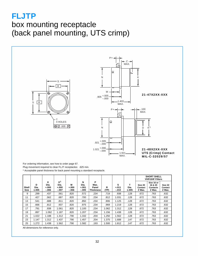
FLJTPbox mounting receptacle(back panel mounting, UTS crimp)
For ordering information, see how to order page 67.Plug movement required to clear FLJT receptacles: .625 min.* Acceptable panel thickness for back panel mounting a standard receptacle.
ShellSize
DDia.
±.005
KDia.
+.000–.006
K1
Dia.+.000–.007
M+.000–.006
NDia.
+.001–.005
PMax.Panel
ThicknessR
(TP)
S+.011–.010
TDia.
±.005
SHORT SHELLVHF/UHF Filters
Size 20ContactZ Max.
Size 16 or 16 & 20
ContactsZ Max.
Size 22ContactZ Max.
9 .299 .437 .561 .820 .572 .234 .719 .938 .128 .672 .763 .632
11 .427 .562 .687 .820 .700 .234 .812 1.031 .128 .672 .763 .632
13 .541 .688 .811 .820 .850 .234 .906 1.125 .128 .672 .763 .632
15 .666 .812 .937 .820 .975 .234 .969 1.219 .128 .672 .763 .632
17 .791 .938 1.061 .820 1.100 .234 1.062 1.312 .128 .672 .763 .632
19 .897 1.062 1.187 .820 1.207 .234 1.156 1.438 .128 .672 .763 .632
21 1.022 1.188 1.312 .790 1.332 .204 1.250 1.562 .128 .672 .763 .632
23 1.147 1.312 1.437 .790 1.457 .204 1.375 1.688 .147 .672 .763 .632
25 1.272 1.438 1.562 .790 1.582 .193 1.500 1.812 .147 .672 .763 .632
All dimensions for reference only.
21-47X2XX-XXX
21-48X2XX-XXXUTS (Crimp) ContactMIL-C-32029/57
33
45˚
W
4-40 UNC-3B THREAD4 PLACES,EQUALLY SPACED
GM
.154±.020
.905+.006–.000
NSEENOTE 1R S
R
S
T4 HOLES
.005 M
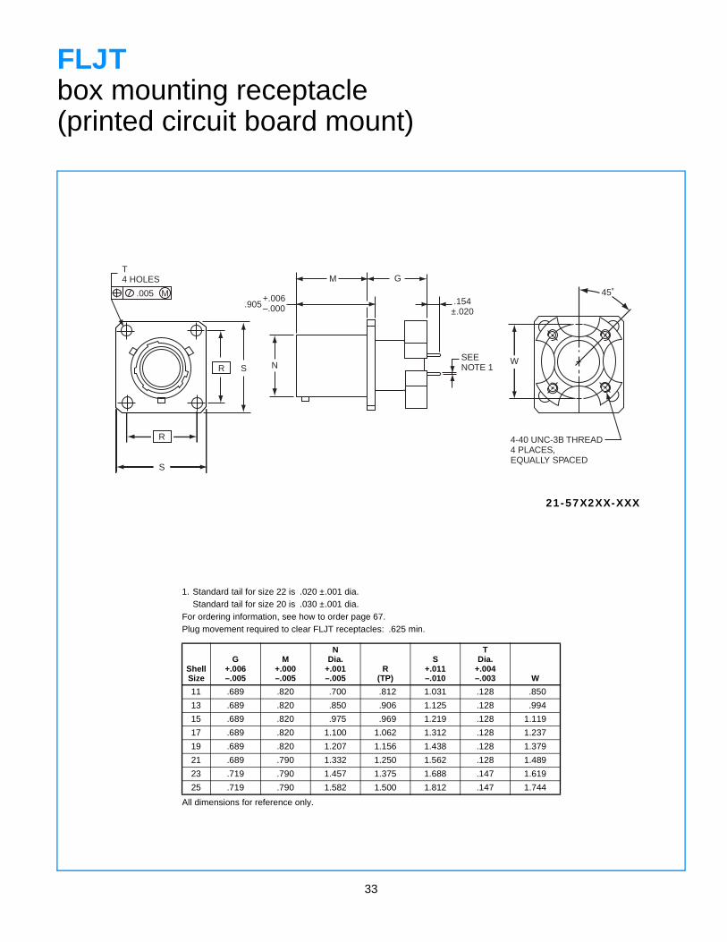
FLJTbox mounting receptacle(printed circuit board mount)
1. Standard tail for size 22 is .020 ±.001 dia.Standard tail for size 20 is .030 ±.001 dia.
For ordering information, see how to order page 67.Plug movement required to clear FLJT receptacles: .625 min.
ShellSize
G+.006–.005
M+.000–.005
NDia.
+.001–.005
R(TP)
S+.011–.010
TDia.
+.004–.003 W
11 .689 .820 .700 .812 1.031 .128 .850
13 .689 .820 .850 .906 1.125 .128 .994
15 .689 .820 .975 .969 1.219 .128 1.119
17 .689 .820 1.100 1.062 1.312 .128 1.237
19 .689 .820 1.207 1.156 1.438 .128 1.379
21 .689 .790 1.332 1.250 1.562 .128 1.489
23 .719 .790 1.457 1.375 1.688 .147 1.619
25 .719 .790 1.582 1.500 1.812 .147 1.744
All dimensions for reference only.
21-57X2XX-XXX
34
S2 PLACES
HHEX
C
A •
T •
V THREADR THREAD
1.403MAX.
.044 DIA. MIN.3 LOCKWIRE HOLES
.915 ±.005
N
PANEL THICKNESS.062 -.0125
Z MAX
.044 DIA. MIN.3 LOCKWIRE HOLES
.915 ±.005 PANEL THICKNESS.062 -.0125
Z MAX.
R THREAD
N
V THREAD
1.931MAX.
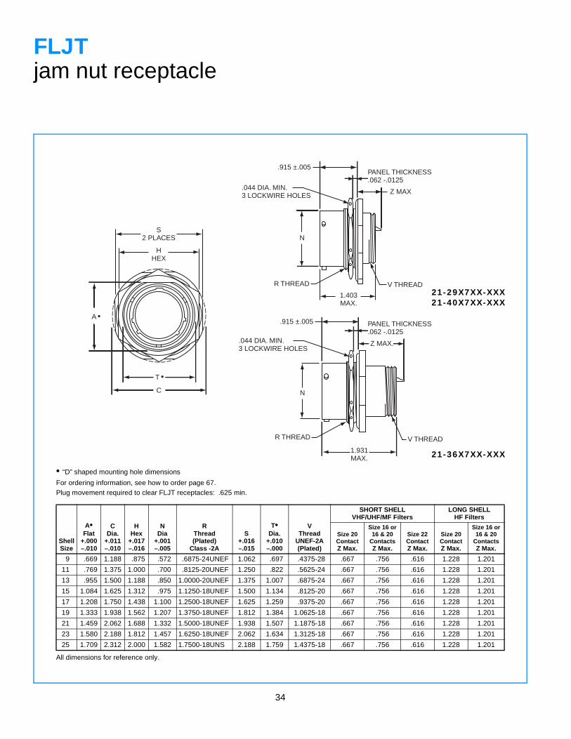
FLJTjam nut receptacle
• “D” shaped mounting hole dimensions
For ordering information, see how to order page 67.Plug movement required to clear FLJT receptacles: .625 min.
ShellSize
A•Flat
+.000–.010
CDia.
+.011–.010
HHex
+.017–.016
NDia
+.001–.005
RThread(Plated)
Class -2A
S+.016–.015
T•Dia.
+.010–.000
VThread
UNEF-2A(Plated)
SHORT SHELLVHF/UHF/MF Filters
LONG SHELLHF Filters
Size 20 ContactZ Max.
Size 16 or16 & 20
ContactsZ Max.
Size 22ContactZ Max.
Size 20ContactZ Max.
Size 16 or16 & 20
ContactsZ Max.
9 .669 1.188 .875 .572 .6875-24UNEF 1.062 .697 .4375-28 .667 .756 .616 1.228 1.201
11 .769 1.375 1.000 .700 .8125-20UNEF 1.250 .822 .5625-24 .667 .756 .616 1.228 1.201
13 .955 1.500 1.188 .850 1.0000-20UNEF 1.375 1.007 .6875-24 .667 .756 .616 1.228 1.201
15 1.084 1.625 1.312 .975 1.1250-18UNEF 1.500 1.134 .8125-20 .667 .756 .616 1.228 1.201
17 1.208 1.750 1.438 1.100 1.2500-18UNEF 1.625 1.259 .9375-20 .667 .756 .616 1.228 1.201
19 1.333 1.938 1.562 1.207 1.3750-18UNEF 1.812 1.384 1.0625-18 .667 .756 .616 1.228 1.201
21 1.459 2.062 1.688 1.332 1.5000-18UNEF 1.938 1.507 1.1875-18 .667 .756 .616 1.228 1.201
23 1.580 2.188 1.812 1.457 1.6250-18UNEF 2.062 1.634 1.3125-18 .667 .756 .616 1.228 1.201
25 1.709 2.312 2.000 1.582 1.7500-18UNS 2.188 1.759 1.4375-18 .667 .756 .616 1.228 1.201
All dimensions for reference only.
21-29X7XX-XXX21-40X7XX-XXX
21-36X7XX-XXX
35
S2 PLACES
HHEX
C
A
•
•
T
PANEL THICKNESS.062 -.125
N
1.922MAX.
G
R THREADV THREAD
D
.100 MAX.
+.005–.000
.921
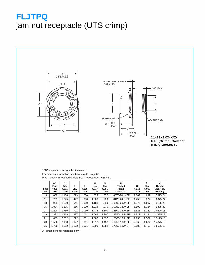
FLJTPQjam nut receptacle (UTS crimp)
• “D” shaped mounting hole dimensions
For ordering information, see how to order page 67.Plug movement required to clear FLJT receptacles: .625 min.
ShellSize
A•Flat
+.000–.010
CDia.
+.011–.010
DDia.
±.005
G+.006–.005
HHex
+.017–.016
NDia
+.001–.005
RThread(Plated)
Class -2A
S+.016–.015
T•Dia.
+.010–.000
VThread
UNEF-2A(Plated)
9 .669 1.188 .299 1.030 .875 .572 .6875-24UNEF 1.062 .697 .5625-24
11 .769 1.375 .427 1.030 1.000 .700 .8125-20UNEF 1.250 .822 .6875-24
13 .955 1.500 .541 1.030 1.188 .850 1.0000-20UNEF 1.375 1.007 .8125-20
15 1.084 1.625 .666 1.030 1.312 .975 1.1250-18UNEF 1.500 1.134 .9375-20
17 1.208 1.750 .791 1.030 1.438 1.100 1.2500-18UNEF 1.625 1.259 1.0625-18
19 1.333 1.938 .897 1.061 1.562 1.207 1.3750-18UNEF 1.812 1.384 1.1875-18
21 1.459 2.062 1.022 1.061 1.688 1.332 1.5000-18UNEF 1.938 1.507 1.3125-18
23 1.580 2.188 1.147 1.061 1.812 1.457 1.6250-18UNEF 2.062 1.634 1.4375-18
25 1.709 2.312 1.272 1.061 2.000 1.582 1.7500-18UNS 2.188 1.759 1.5625-18
All dimensions for reference only.
21-48X7XX-XXXUTS (Crimp) ContactMIL-C-39029/57
36
4-40 UNC-3BTHREAD4 SPACESEQUALLY SPACED
W
45˚
SEE NOTE 1
1.183±.005
.110
.326 ±.002
S
RR THREAD
SPANNER NUT
RR THREAD
SPANNER NUT
.075 MAX.BULKHEAD
.125±.005
B2 PLACES
+.000–.010.932
SEE NOTE 1
.836±.005
.110
.326 ±.002
S.575 ±.010
.673 ±.002
.075 MAX.BULKHEAD
.125±.005
B2 PLACESN
N
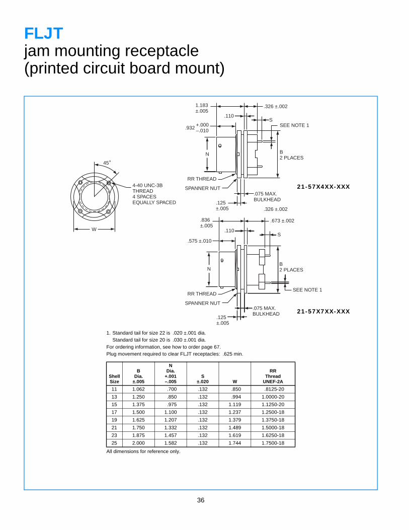
FLJTjam mounting receptacle(printed circuit board mount)
1. Standard tail for size 22 is .020 ±.001 dia.Standard tail for size 20 is .030 ±.001 dia.
For ordering information, see how to order page 67.Plug movement required to clear FLJT receptacles: .625 min.
ShellSize
BDia.
±.005
NDia.
+.001–.005
S±.020 W
RRThread
UNEF-2A
11 1.062 .700 .132 .850 .8125-20
13 1.250 .850 .132 .994 1.0000-20
15 1.375 .975 .132 1.119 1.1250-20
17 1.500 1.100 .132 1.237 1.2500-18
19 1.625 1.207 .132 1.379 1.3750-18
21 1.750 1.332 .132 1.489 1.5000-18
23 1.875 1.457 .132 1.619 1.6250-18
25 2.000 1.582 .132 1.744 1.7500-18
All dimensions for reference only.
21-57X7XX-XXX
21-57X4XX-XXX
37
S2 PLACES
HHEX
C
A•
T•
M
Z MIN.
N
.044 DIA. MIN.3 LOCKWIRE HOLES
PANEL THICKNESS.062 to .603 Sizes 9-19.062 to 572 Sizes 21-25
R THREAD
1.686MAX.
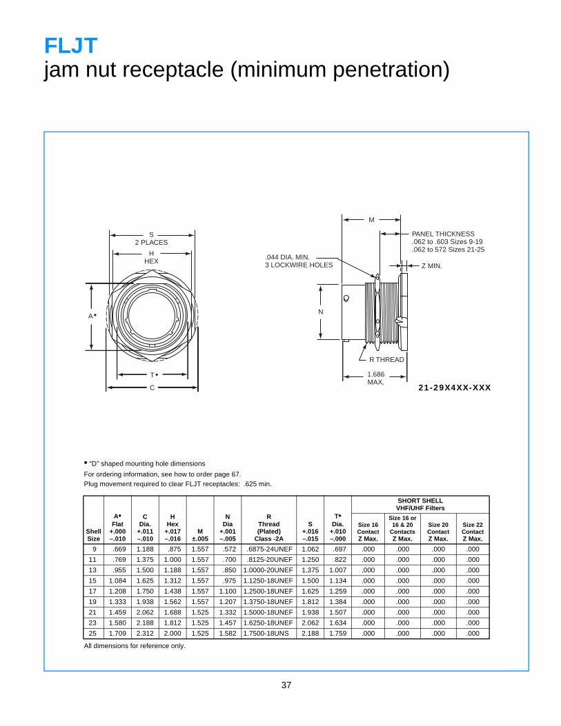
FLJTjam nut receptacle (minimum penetration)
• “D” shaped mounting hole dimensions
For ordering information, see how to order page 67.Plug movement required to clear FLJT receptacles: .625 min.
ShellSize
A•Flat
+.000–.010
CDia.
+.011–.010
HHex
+.017–.016
M±.005
NDia
+.001–.005
RThread(Plated)
Class -2A
S+.016–.015
T•Dia.
+.010–.000
SHORT SHELLVHF/UHF Filters
Size 16 ContactZ Max.
Size 16 or16 & 20
ContactsZ Max.
Size 20ContactZ Max.
Size 22ContactZ Max.
9 .669 1.188 .875 1.557 .572 .6875-24UNEF 1.062 .697 .000 .000 .000 .000
11 .769 1.375 1.000 1.557 .700 .8125-20UNEF 1.250 .822 .000 .000 .000 .000
13 .955 1.500 1.188 1.557 .850 1.0000-20UNEF 1.375 1.007 .000 .000 .000 .000
15 1.084 1.625 1.312 1.557 .975 1.1250-18UNEF 1.500 1.134 .000 .000 .000 .000
17 1.208 1.750 1.438 1.557 1.100 1.2500-18UNEF 1.625 1.259 .000 .000 .000 .000
19 1.333 1.938 1.562 1.557 1.207 1.3750-18UNEF 1.812 1.384 .000 .000 .000 .000
21 1.459 2.062 1.688 1.525 1.332 1.5000-18UNEF 1.938 1.507 .000 .000 .000 .000
23 1.580 2.188 1.812 1.525 1.457 1.6250-18UNEF 2.062 1.634 .000 .000 .000 .000
25 1.709 2.312 2.000 1.525 1.582 1.7500-18UNS 2.188 1.759 .000 .000 .000 .000
All dimensions for reference only.
21-29X4XX-XXX
38
RELATIVE POSSIBLE POSITIONOF ROTATED MASTER KEYWAY (front face of receptacle shown)
ROTATIONLETTERS
NORMAL
B A D C
AB
5˚ REF
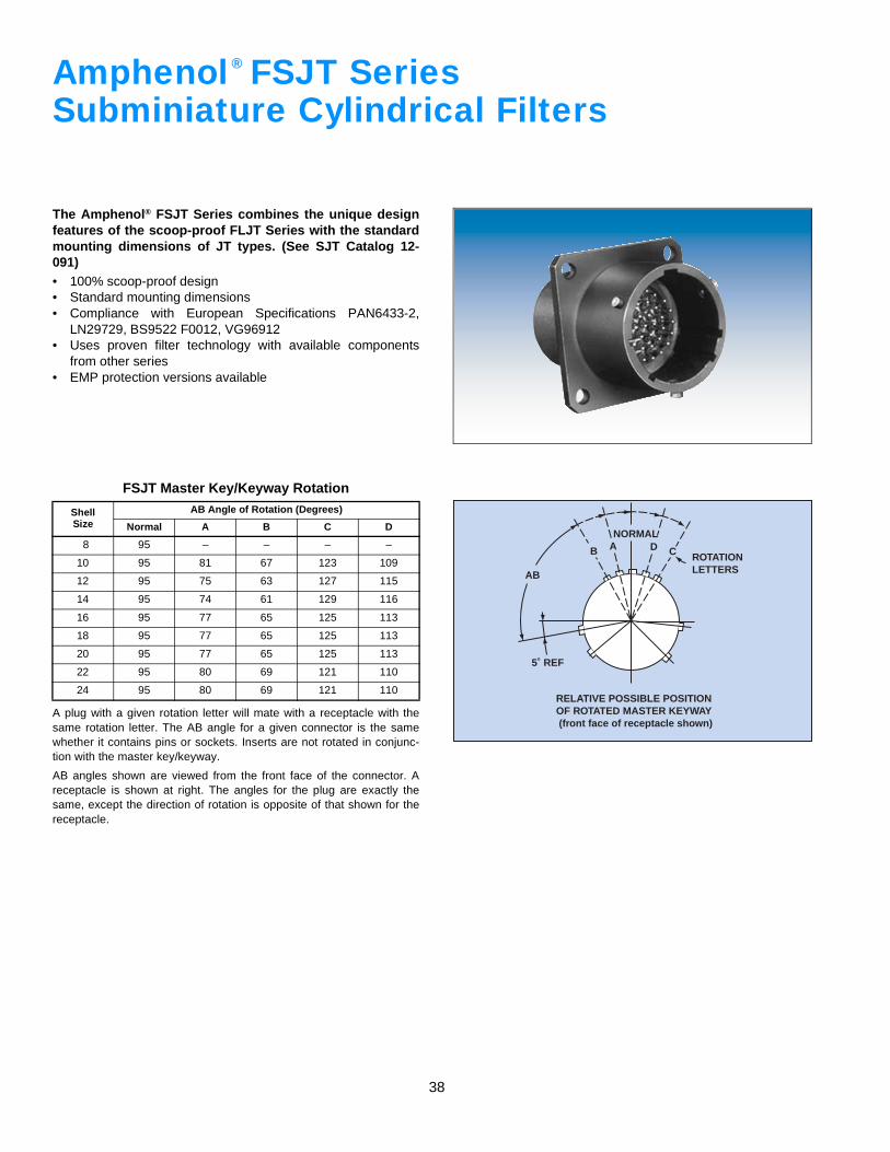
Amphenol FSJT SeriesSubminiature Cylindrical Filters
The Amphenol® FSJT Series combines the unique designfeatures of the scoop-proof FLJT Series with the standardmounting dimensions of JT types. (See SJT Catalog 12-091)• 100% scoop-proof design• Standard mounting dimensions• Compliance with European Specifications PAN6433-2,
LN29729, BS9522 F0012, VG96912• Uses proven filter technology with available components
from other series• EMP protection versions available
A plug with a given rotation letter will mate with a receptacle with thesame rotation letter. The AB angle for a given connector is the samewhether it contains pins or sockets. Inserts are not rotated in conjunc-tion with the master key/keyway.
AB angles shown are viewed from the front face of the connector. Areceptacle is shown at right. The angles for the plug are exactly thesame, except the direction of rotation is opposite of that shown for thereceptacle.
FSJT Master Key/Keyway Rotation
ShellSize
AB Angle of Rotation (Degrees)
Normal A B C D
8 95 – – – –
10 95 81 67 123 109
12 95 75 63 127 115
14 95 74 61 129 116
16 95 77 65 125 113
18 95 77 65 125 113
20 95 77 65 125 113
22 95 80 69 121 110
24 95 80 69 121 110
®
39
R
R
S
S
T DIA.4 HOLES
.005 M
1.506 MAX.
.717+.006–.000
N
M
V THREAD
Z
.312MIN. FULL THREAD
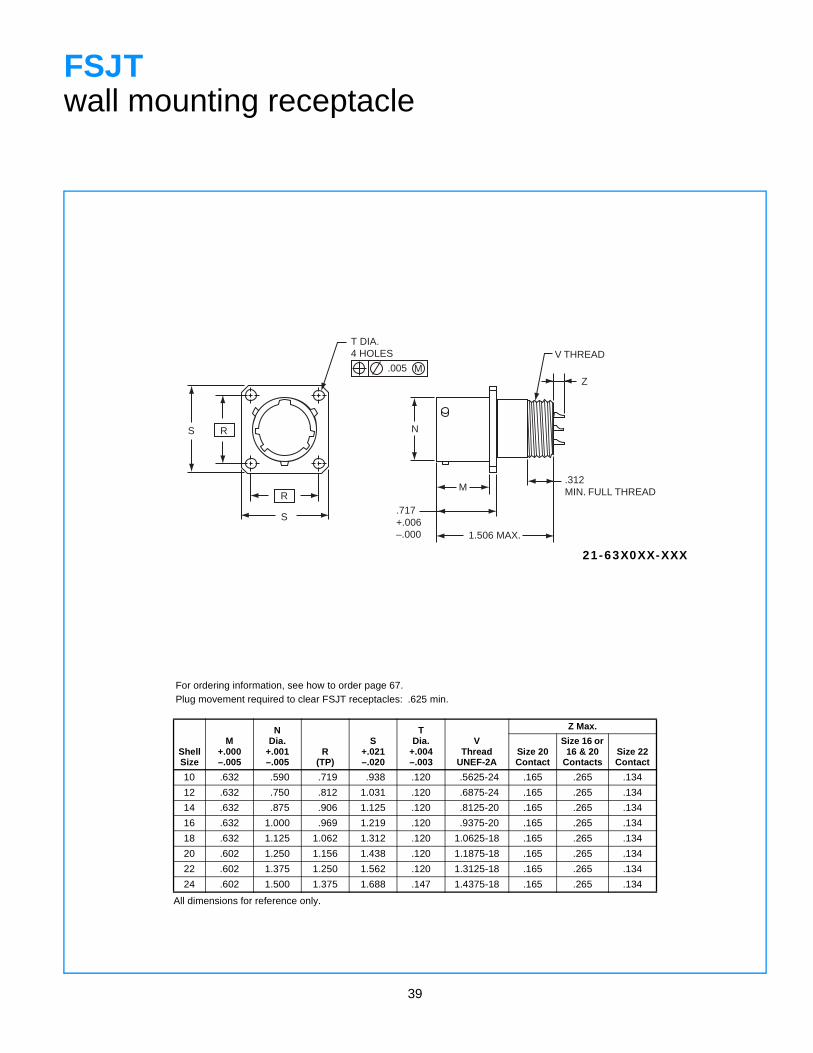
FSJTwall mounting receptacle
For ordering information, see how to order page 67.Plug movement required to clear FSJT receptacles: .625 min.
ShellSize
M+.000–.005
NDia.
+.001–.005
R(TP)
S+.021–.020
TDia.
+.004–.003
VThread
UNEF-2A
Z Max.
Size 20 Contact
Size 16 or 16 & 20
ContactsSize 22 Contact
10 .632 .590 .719 .938 .120 .5625-24 .165 .265 .134
12 .632 .750 .812 1.031 .120 .6875-24 .165 .265 .134
14 .632 .875 .906 1.125 .120 .8125-20 .165 .265 .134
16 .632 1.000 .969 1.219 .120 .9375-20 .165 .265 .134
18 .632 1.125 1.062 1.312 .120 1.0625-18 .165 .265 .134
20 .602 1.250 1.156 1.438 .120 1.1875-18 .165 .265 .134
22 .602 1.375 1.250 1.562 .120 1.3125-18 .165 .265 .134
24 .602 1.500 1.375 1.688 .147 1.4375-18 .165 .265 .134
All dimensions for reference only.
21-63X0XX-XXX
40
R
R
S
S
.005 M
T DIA. 4 HOLES
N
1.922 MAX.
.717+.006–.000
V THREAD
.100 MAX.
D
M.312MIN. FULL THREAD
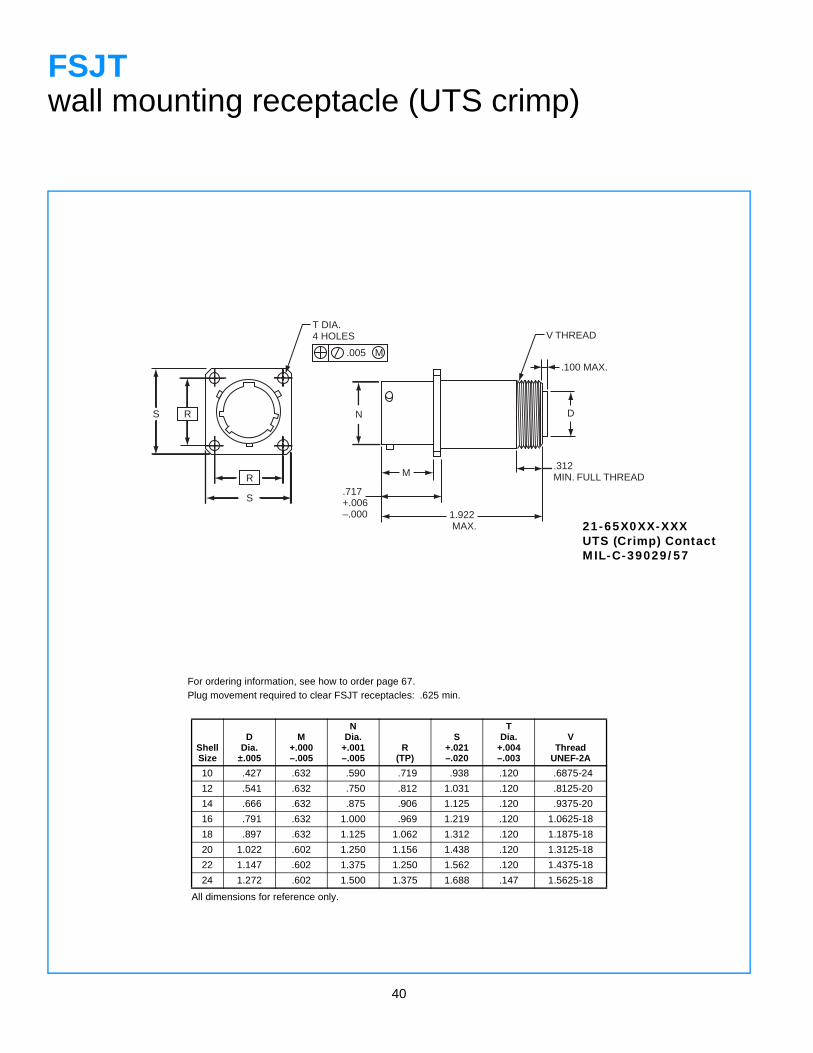
FSJTwall mounting receptacle (UTS crimp)
For ordering information, see how to order page 67.Plug movement required to clear FSJT receptacles: .625 min.
ShellSize
DDia.
±.005
M+.000–.005
NDia.
+.001–.005
R(TP)
S+.021–.020
TDia.
+.004–.003
VThread
UNEF-2A
10 .427 .632 .590 .719 .938 .120 .6875-24
12 .541 .632 .750 .812 1.031 .120 .8125-20
14 .666 .632 .875 .906 1.125 .120 .9375-20
16 .791 .632 1.000 .969 1.219 .120 1.0625-18
18 .897 .632 1.125 1.062 1.312 .120 1.1875-18
20 1.022 .602 1.250 1.156 1.438 .120 1.3125-18
22 1.147 .602 1.375 1.250 1.562 .120 1.4375-18
24 1.272 .602 1.500 1.375 1.688 .147 1.5625-18
All dimensions for reference only.
21-65X0XX-XXXUTS (Crimp) ContactMIL-C-39029/57
41
R
R
S
S
.005 M
T DIA. 4 HOLES
EE
Z
N
M
1.506 MAX
.717+.006–.000
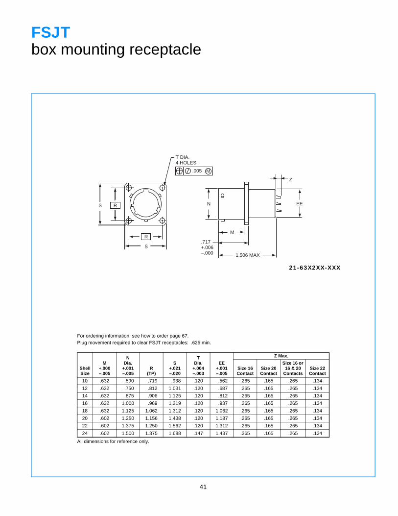
FSJTbox mounting receptacle
For ordering information, see how to order page 67.Plug movement required to clear FSJT receptacles: .625 min.
ShellSize
M+.000–.005
NDia.
+.001–.005
R(TP)
S+.021–.020
TDia.
+.004–.003
EE+.001–.005
Z Max.
Size 16Contact
Size 20 Contact
Size 16 or 16 & 20
ContactsSize 22 Contact
10 .632 .590 .719 .938 .120 .562 .265 .165 .265 .134
12 .632 .750 .812 1.031 .120 .687 .265 .165 .265 .134
14 .632 .875 .906 1.125 .120 .812 .265 .165 .265 .134
16 .632 1.000 .969 1.219 .120 .937 .265 .165 .265 .134
18 .632 1.125 1.062 1.312 .120 1.062 .265 .165 .265 .134
20 .602 1.250 1.156 1.438 .120 1.187 .265 .165 .265 .134
22 .602 1.375 1.250 1.562 .120 1.312 .265 .165 .265 .134
24 .602 1.500 1.375 1.688 .147 1.437 .265 .165 .265 .134
All dimensions for reference only.
21-63X2XX-XXX
42
R
R
S
S
.005 M
T DIA. 4 HOLES
N
.717+.006–.000
M
1.922 MAX.
D EE
.100 MAX.
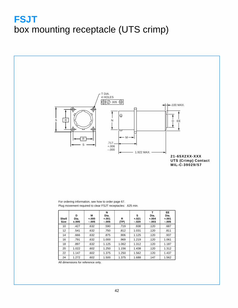
FSJTbox mounting receptacle (UTS crimp)
For ordering information, see how to order page 67.Plug movement required to clear FSJT receptacles: .625 min.
ShellSize
DDia.
±.005
M+.000–.005
NDia.
+.001–.005
R(TP)
S+.021–.020
TDia.
+.004–.003
EEDia.
+.001–.005
10 .427 .632 .590 .719 .938 .120 .687
12 .541 .632 .750 .812 1.031 .120 .811
14 .666 .632 .875 .906 1.125 .120 .937
16 .791 .632 1.000 .969 1.219 .120 1.061
18 .897 .632 1.125 1.062 1.312 .120 1.187
20 1.022 .602 1.250 1.156 1.438 .120 1.312
22 1.147 .602 1.375 1.250 1.562 .120 1.437
24 1.272 .602 1.500 1.375 1.688 .147 1.562
All dimensions for reference only.
21-65X2XX-XXXUTS (Crimp) ContactMIL-C-39029/57
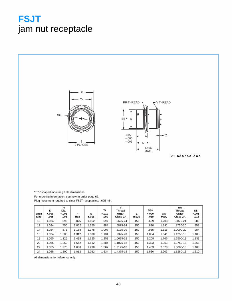
43
P
S2 PLACES
GG
T •RR THREAD V THREAD
Z
K
1.506MAX.
N
.915+.006–.005
BB •
FSJTjam nut receptacle
• “D” shaped mounting hole dimensions
For ordering information, see how to order page 67.Plug movement required to clear FSJT receptacles: .625 min.
ShellSize
K+.006–.005
NDia.
+.001–.005
PHex
S±.016
T•+.010–.000
VThreadUNEF
Class 2AZ
±.020
BB•+.000–.010
GGMax.
RRThreadUNEF
Class 2A
SS+.001–.016
10 1.024 .590 .875 1.062 .697 .5625-24 .150 .669 1.203 .6875-24 .680
12 1.024 .750 1.062 1.250 .884 .6875-24 .150 .830 1.391 .8750-20 .859
14 1.024 .875 1.188 1.375 1.007 .8125-20 .150 .955 1.515 1.0000-20 .984
16 1.024 1.000 1.312 1.500 1.134 .9375-20 .150 1.084 1.641 1.1250-18 1.108
18 1.055 1.125 1.438 1.625 1.259 1.0625-18 .150 1.208 1.766 1.2500-18 1.233
20 1.055 1.250 1.562 1.812 1.384 1.1875-18 .150 1.333 1.953 1.3750-18 1.358
22 1.055 1.375 1.688 1.938 1.507 1.3125-18 .150 1.459 2.078 1.5000-18 1.483
24 1.055 1.500 1.812 2.062 1.634 1.4375-18 .150 1.580 2.203 1.6250-18 1.610
All dimensions for reference only.
21-63X7XX-XXX
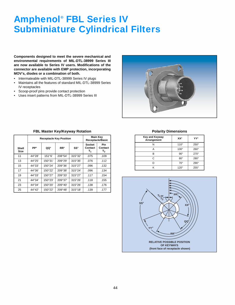
44
orT1T2
PP˚
XX˚
QQ˚
RELATIVE POSSIBLE POSITIONOF KEYWAYS
(front face of receptacle shown)
RR˚
YY˚
SS˚
Amphenol FBL Series IVSubminiature Cylindrical Filters
Components designed to meet the severe mechanical andenvironmental requirements of MIL-DTL-38999 Series IIIare now available to Series IV users. Modifications of theconnector are available with EMP protection, incorporatingMOV’s, diodes or a combination of both.• Intermateable with MIL-DTL-38999 Series IV plugs• Maintains all the features of standard MIL-DTL-38999 Series
IV receptacles• Scoop-proof pins provide contact protection• Uses insert patterns from MIL-DTL-38999 Series III
FBL Master Key/Keyway Rotation
ShellSize
Receptacle Key Position Main KeyReceptacle/Basic
PP° QQ° RR° SS°Socket Contact
T1
Pin Contact
T2
11 44°28’ 151°6’ 208°54’ 315°32’ .075 .109
13 44°25’ 150°31’ 209°29’ 315°35’ .076 .112
15 44°33’ 150°24’ 209°36’ 315°27’ .096 .132
17 44°36’ 150°22’ 209°38’ 315°24’ .096 .134
19 44°33’ 150°27’ 209°33’ 315°27’ .117 .154
21 44°34’ 150°23’ 209°37’ 315°26’ .118 .155
23 44°34’ 150°20’ 209°40’ 315°26’ .138 .176
25 44°42’ 150°22’ 209°48’ 315°18’ .139 .177
Polarity DimensionsKey and Keyway
Arrangement XX° YY°
N 110° 250°
A 100° 260°
B 90° 270°
C 80° 280°
D 70° 290°
K 120° 255°
®
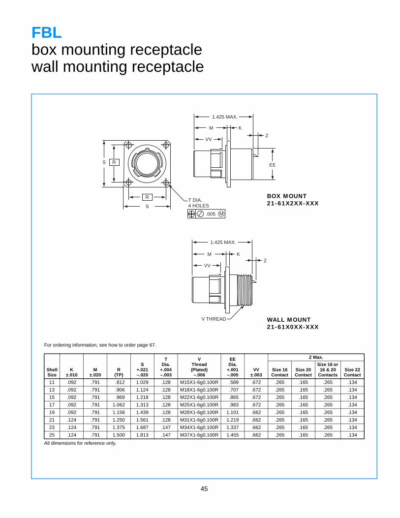
45
S R
S
RT DIA.4 HOLES
.005 M
1.425 MAX.
M K
ZVV
1.425 MAX.
M KZ
VV
EE
V THREAD
FBLbox mounting receptaclewall mounting receptacle
For ordering information, see how to order page 67.
ShellSize
K±.010
M±.020
R(TP)
S+.021–.020
TDia.
+.004–.003
VThread(Plated)
–.006
EEDia.
+.001–.005
VV±.003
Z Max.
Size 16Contact
Size 20 Contact
Size 16 or 16 & 20
ContactsSize 22 Contact
11 .092 .791 .812 1.029 .128 M15X1-6g0.100R .589 .672 .265 .165 .265 .134
13 .092 .791 .906 1.124 .128 M18X1-6g0.100R .707 .672 .265 .165 .265 .134
15 .092 .791 .969 1.218 .128 M22X1-6g0.100R .865 .672 .265 .165 .265 .134
17 .092 .791 1.062 1.313 .128 M25X1-6g0.100R .983 .672 .265 .165 .265 .134
19 .092 .791 1.156 1.439 .128 M28X1-6g0.100R 1.101 .662 .265 .165 .265 .134
21 .124 .791 1.250 1.561 .128 M31X1-6g0.100R 1.219 .662 .265 .165 .265 .134
23 .124 .791 1.375 1.687 .147 M34X1-6g0.100R 1.337 .662 .265 .165 .265 .134
25 .124 .791 1.500 1.813 .147 M37X1-6g0.100R 1.455 .662 .265 .165 .265 .134
All dimensions for reference only.
WALL MOUNT21-61X0XX-XXX
BOX MOUNT21-61X2XX-XXX
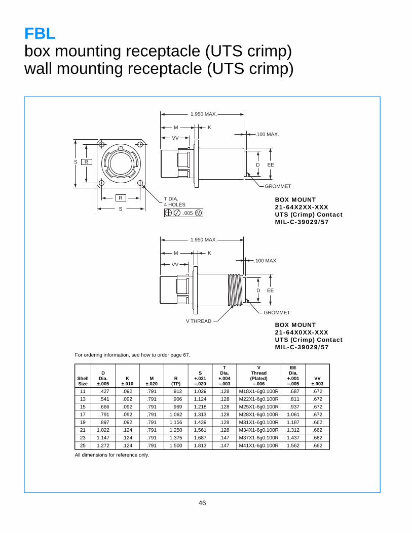
46
R
S
RS
T DIA.4 HOLES
.005 M
1.950 MAX.
K
VV.100 MAX.
D EE
GROMMET
GROMMET
V THREAD
M
1.950 MAX.
K
VV.100 MAX.
D EE
M
FBLbox mounting receptacle (UTS crimp)wall mounting receptacle (UTS crimp)
For ordering information, see how to order page 67.
ShellSize
DDia.
±.005K
±.010M
±.020R
(TP)
S+.021–.020
TDia.
+.004–.003
VThread(Plated)
–.006
EEDia.
+.001–.005
VV±.003
11 .427 .092 .791 .812 1.029 .128 M18X1-6g0.100R .687 .672
13 .541 .092 .791 .906 1.124 .128 M22X1-6g0.100R .811 .672
15 .666 .092 .791 .969 1.218 .128 M25X1-6g0.100R .937 .672
17 .791 .092 ,791 1.062 1.313 .128 M28X1-6g0.100R 1.061 .672
19 .897 .092 .791 1.156 1.439 .128 M31X1-6g0.100R 1.187 .662
21 1.022 .124 .791 1.250 1.561 .128 M34X1-6g0.100R 1.312 .662
23 1.147 .124 .791 1.375 1.687 .147 M37X1-6g0.100R 1.437 .662
25 1.272 .124 .791 1.500 1.813 .147 M41X1-6g0.100R 1.562 .662
All dimensions for reference only.
BOX MOUNT21-64X2XX-XXXUTS (Crimp) ContactMIL-C-39029/57
BOX MOUNT21-64X0XX-XXXUTS (Crimp) ContactMIL-C-39029/57
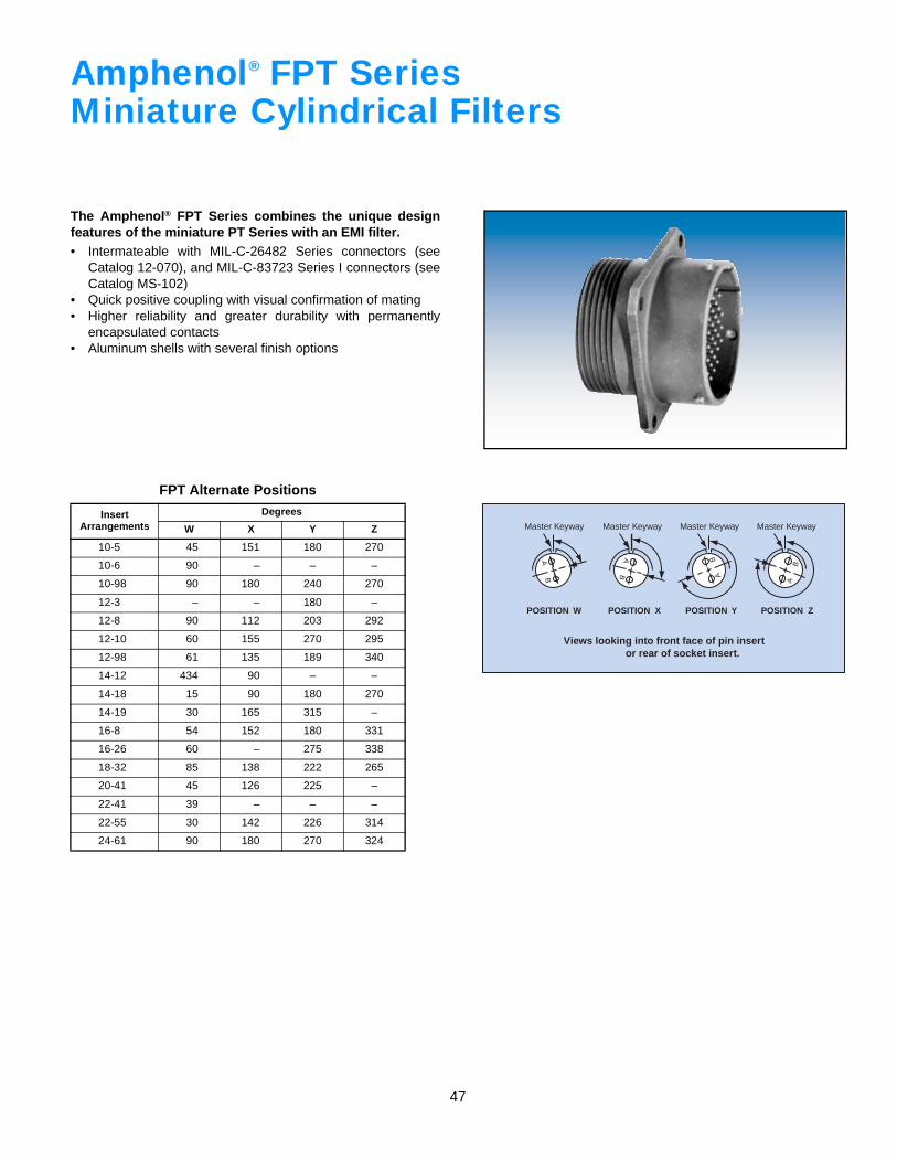
47
AB
Master Keyway
POSITION W
Master Keyway
POSITION X
Master Keyway
POSITION Y
Master Keyway
POSITION Z
Views looking into front face of pin insert or rear of socket insert.
AB A
B
BA
Amphenol FPT SeriesMiniature Cylindrical Filters
The Amphenol® FPT Series combines the unique designfeatures of the miniature PT Series with an EMI filter.• Intermateable with MIL-C-26482 Series connectors (see
Catalog 12-070), and MIL-C-83723 Series I connectors (seeCatalog MS-102)
• Quick positive coupling with visual confirmation of mating• Higher reliability and greater durability with permanently
encapsulated contacts• Aluminum shells with several finish options
FPT Alternate Positions
Insert Arrangements
Degrees
W X Y Z
10-5 45 151 180 270
10-6 90 – – –
10-98 90 180 240 270
12-3 – – 180 –
12-8 90 112 203 292
12-10 60 155 270 295
12-98 61 135 189 340
14-12 434 90 – –
14-18 15 90 180 270
14-19 30 165 315 –
16-8 54 152 180 331
16-26 60 – 275 338
18-32 85 138 222 265
20-41 45 126 225 –
22-41 39 – – –
22-55 30 142 226 314
24-61 90 180 270 324
®
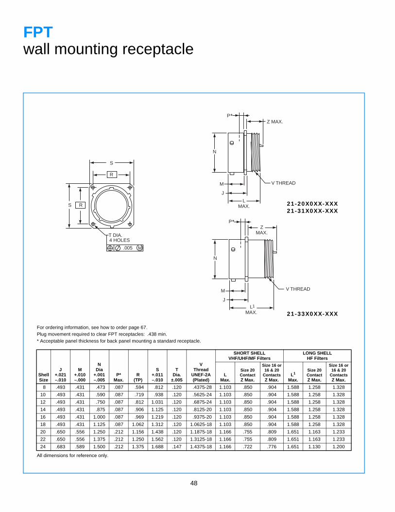
48
S R
S
R
T DIA.4 HOLES
.005 M
Z MAX.
N
LMAX.
M
J
V THREAD
M
J
ZMAX.
N
V THREAD
P*
P*
LMAX.
1
FPTwall mounting receptacle
For ordering information, see how to order page 67.Plug movement required to clear FPT receptacles: .438 min.* Acceptable panel thickness for back panel mounting a standard receptacle.
ShellSize
J+.021–.010
M+.010–.000
NDia
+.001–.005
P*Max.
R(TP)
S+.011–.010
TDia.
±.005
VThread
UNEF-2A(Plated)
SHORT SHELLVHF/UHF/MF Filters
LONG SHELLHF Filters
LMax.
Size 20ContactZ Max.
Size 16 or16 & 20
ContactsZ Max.
L1
Max.
Size 20ContactZ Max.
Size 16 or16 & 20
ContactsZ Max.
8 .493 .431 .473 .087 .594 .812 .120 .4375-28 1.103 .850 .904 1.588 1.258 1.328
10 .493 .431 .590 .087 .719 .938 .120 .5625-24 1.103 .850 .904 1.588 1.258 1.328
12 .493 .431 .750 .087 .812 1.031 .120 .6875-24 1.103 .850 .904 1.588 1.258 1.328
14 .493 .431 .875 .087 .906 1.125 .120 .8125-20 1.103 .850 .904 1.588 1.258 1.328
16 .493 .431 1.000 .087 .969 1.219 .120 .9375-20 1.103 .850 .904 1.588 1.258 1.328
18 .493 .431 1.125 .087 1.062 1.312 .120 1.0625-18 1.103 .850 .904 1.588 1.258 1.328
20 .650 .556 1.250 .212 1.156 1.438 .120 1.1875-18 1.166 .755 .809 1.651 1.163 1.233
22 .650 .556 1.375 .212 1.250 1.562 .120 1.3125-18 1.166 .755 .809 1.651 1.163 1.233
24 .683 .589 1.500 .212 1.375 1.688 .147 1.4375-18 1.166 .722 .776 1.651 1.130 1.200
All dimensions for reference only.
21-20X0XX-XXX21-31X0XX-XXX
21-33X0XX-XXX
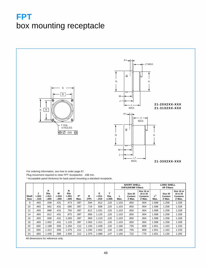
49
RS
T DIA.4 HOLES
.005
S
R
M
Z MAX.
KN
M
J
LMAX.
P*
ZMAX.
KN
M
JL
MAX.1
*P
FPTbox mounting receptacle
For ordering information, see how to order page 67.Plug movement required to clear FPT receptacles: .438 min.* Acceptable panel thickness for back panel mounting a standard receptacle.
ShellSize
J+.021–.010
KDia.
+.011–.000
M+.010–.000
NDia
+.001–.005
P*Max.
R(TP)
S+.011–.010
TDia.
±.005
SHORT SHELLVHF/UHF/MF Filters
LONG SHELLHF Filters
LMax.
Size 20ContactZ Max.
Size 16 or16 & 20
ContactsZ Max.
L1
Max.
Size 20ContactZ Max.
Size 16 or16 & 20
ContactsZ Max.
8 .493 .438 .431 .473 .087 .594 .812 .120 1.103 .850 .904 1.588 1.258 1.328
10 .493 .562 .431 .590 .087 .719 .938 .120 1.103 .850 .904 1.588 1.258 1.328
12 .493 .688 .431 .750 .087 .812 1.031 .120 1.103 .850 .904 1.588 1.258 1.328
14 .493 .812 .431 .875 .087 .906 1.125 .120 1.103 .850 .904 1.588 1.258 1.328
16 .493 .938 .431 1.000 .087 .969 1.219 .120 1.103 .850 .904 1.588 1.258 1.328
18 .493 1.062 .431 1.125 .087 1.062 1.312 .120 1.103 .850 .904 1.588 1.258 1.328
20 .650 1.188 .556 1.250 .212 1.156 1.438 .120 1.166 .755 .809 1.651 1.163 1.233
22 .650 1.312 .556 1.375 .212 1.250 1.562 .120 1.166 .755 .809 1.651 1.163 1.233
24 .683 1.438 .589 1.500 .212 1.375 1.688 .147 1.166 .722 .776 1.651 1.130 1.200
All dimensions for reference only.
21-20X2XX-XXX21-31X2XX-XXX
21-33X2XX-XXX
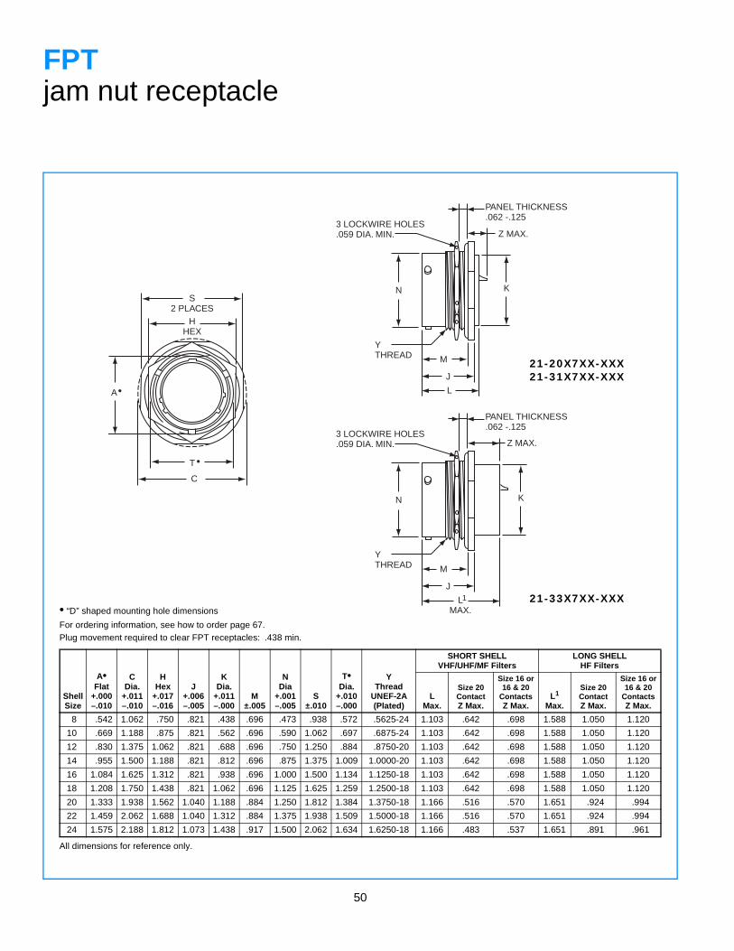
50
S2 PLACES
HHEX
C
A•
T •
3 LOCKWIRE HOLES.059 DIA. MIN.
PANEL THICKNESS.062 -.125
KN
YTHREAD M
J
L
Z MAX.
3 LOCKWIRE HOLES.059 DIA. MIN.
PANEL THICKNESS.062 -.125
KN
YTHREAD M
J
LMAX.
Z MAX.
1
FPTjam nut receptacle
• “D” shaped mounting hole dimensions
For ordering information, see how to order page 67.Plug movement required to clear FPT receptacles: .438 min.
ShellSize
A•Flat
+.000–.010
CDia.
+.011–.010
HHex
+.017–.016
J+.006–.005
KDia.
+.011–.000
M±.005
NDia
+.001–.005
S±.010
T•Dia.
+.010–.000
YThread
UNEF-2A (Plated)
SHORT SHELLVHF/UHF/MF Filters
LONG SHELLHF Filters
LMax.
Size 20ContactZ Max.
Size 16 or16 & 20
ContactsZ Max.
L1
Max.
Size 20ContactZ Max.
Size 16 or16 & 20
ContactsZ Max.
8 .542 1.062 .750 .821 .438 .696 .473 .938 .572 .5625-24 1.103 .642 .698 1.588 1.050 1.120
10 .669 1.188 .875 .821 .562 .696 .590 1.062 .697 .6875-24 1.103 .642 .698 1.588 1.050 1.120
12 .830 1.375 1.062 .821 .688 .696 .750 1.250 .884 .8750-20 1.103 .642 .698 1.588 1.050 1.120
14 .955 1.500 1.188 .821 .812 .696 .875 1.375 1.009 1.0000-20 1.103 .642 .698 1.588 1.050 1.120
16 1.084 1.625 1.312 .821 .938 .696 1.000 1.500 1.134 1.1250-18 1.103 .642 .698 1.588 1.050 1.120
18 1.208 1.750 1.438 .821 1.062 .696 1.125 1.625 1.259 1.2500-18 1.103 .642 .698 1.588 1.050 1.120
20 1.333 1.938 1.562 1.040 1.188 .884 1.250 1.812 1.384 1.3750-18 1.166 .516 .570 1.651 .924 .994
22 1.459 2.062 1.688 1.040 1.312 .884 1.375 1.938 1.509 1.5000-18 1.166 .516 .570 1.651 .924 .994
24 1.575 2.188 1.812 1.073 1.438 .917 1.500 2.062 1.634 1.6250-18 1.166 .483 .537 1.651 .891 .961
All dimensions for reference only.
21-20X7XX-XXX21-31X7XX-XXX
21-33X7XX-XXX
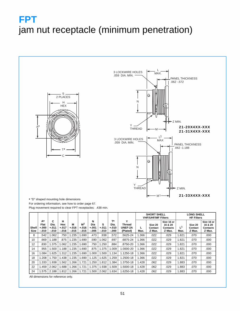
51
N
3 LOCKWIRE HOLES.059 DIA. MIN.
PANEL THICKNESS.062 -.572
LMAX.
YTHREAD M
Z MIN.
N
3 LOCKWIRE HOLES.059 DIA. MIN.
PANEL THICKNESS.062 -1.188
L
YTHREAD Z MIN.
M1
MAX1
S2 PLACES
HHEX
C
A•
T•
FPTjam nut receptacle (minimum penetration)
• “D” shaped mounting hole dimensions
For ordering information, see how to order page 67.Plug movement required to clear FPT receptacles: .438 min.
ShellSize
A•Flat
+.000–.010
CDia.
+.011–.010
HHex
+.017–.016
M+.016–.015
M1
+.016–.015
NDia
+.001–.005
S+.011–.010
T•Dia.
+.010–.000
YThread
UNEF-2A (Plated)
SHORT SHELLVHF/UHF/MF Filters
LONG SHELLHF Filters
LMax.
Size 20ContactZ Max.
Size 16 or16 & 20
ContactsZ Max.
L1
Max.
Size 20ContactZ Max.
Size 16 or16 & 20
ContactsZ Max.
8 .542 1.062 .750 1.235 1.690 .473 .938 .572 .5625-24 1.366 .022 .029 1.821 .070 .000
10 .669 1.188 .875 1.235 1.690 .590 1.062 .697 .6875-24 1.366 .022 .029 1.821 .070 .000
12 .830 1.375 1.062 1.235 1.690 .750 1.250 .884 .8750-20 1.366 .022 .029 1.821 .070 .000
14 .955 1.500 1.188 1.235 1.690 .875 1.375 1.009 1.0000-20 1.366 .022 .029 1.821 .070 .000
16 1.084 1.625 1.312 1.235 1.690 1.000 1.500 1.134 1.1250-18 1.366 .022 .029 1.821 .070 .000
18 1.208 1.750 1.438 1.235 1.690 1.125 1.625 1.259 1.2500-18 1.366 .022 .029 1.821 .070 .000
20 1.333 1.938 1.562 1.266 1.721 1.250 1.812 1.384 1.3750-18 1.428 .062 .029 1.883 .070 .000
22 1.459 2.062 1.688 1.266 1.721 1.375 1.938 1.509 1.5000-18 1.428 .062 .029 1.883 .070 .000
24 1.575 2.188 1.812 1.266 1.721 1.500 2.062 1.634 1.6250-18 1.428 .062 .029 1.883 .070 .000
All dimensions for reference only.
21-20X4XX-XXX21-31X4XX-XXX
21-33X4XX-XXX
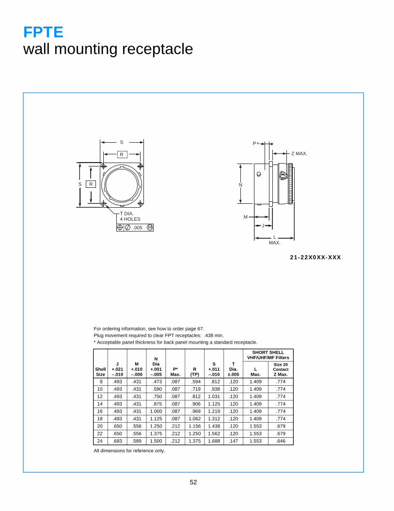
52
RS
T DIA.4 HOLES
.005
S
R
M
Z MAX.
N
M
J
LMAX.
P*
FPTEwall mounting receptacle
For ordering information, see how to order page 67.Plug movement required to clear FPT receptacles: .438 min.* Acceptable panel thickness for back panel mounting a standard receptacle.
ShellSize
J+.021–.010
M+.010–.000
NDia
+.001–.005
P*Max.
R(TP)
S+.011–.010
TDia.
±.005
SHORT SHELLVHF/UHF/MF Filters
LMax.
Size 20ContactZ Max.
8 .493 .431 .473 .087 .594 .812 .120 1.409 .774
10 .493 .431 .590 .087 .719 .938 .120 1.409 .774
12 .493 .431 .750 .087 .812 1.031 .120 1.409 .774
14 .493 .431 .875 .087 .906 1.125 .120 1.409 .774
16 .493 .431 1.000 .087 .969 1.219 .120 1.409 .774
18 .493 .431 1.125 .087 1.062 1.312 .120 1.409 .774
20 .650 .556 1.250 .212 1.156 1.438 .120 1.553 .679
22 .650 .556 1.375 .212 1.250 1.562 .120 1.553 .679
24 .683 .589 1.500 .212 1.375 1.688 .147 1.553 .646
All dimensions for reference only.
21-22X0XX-XXX
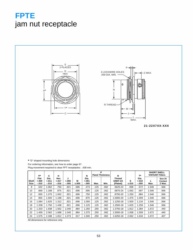
53
N
3 LOCKWIRE HOLES.059 DIA. MIN.
P
Z MAX.
R THREAD
M
J
LMAX.
S2 PLACES
HHEX
C
A•
T•
FPTEjam nut receptacle
• “D” shaped mounting hole dimensions
For ordering information, see how to order page 67.Plug movement required to clear FPT receptacles: .438 min.
ShellSize
A•Flat
+.000–.010
CDia.
+.011–.010
HHex
+.017–.016
J+.006–.005
M±.005
NDia.
+.001–.005
PPanel Thickness R
ThreadUNEF-2A (Plated)
S±.010
T•Dia.
+.010–.000
SHORT SHELLVHF/UHF Filters
Max. Min.L
Max.
Size 20ContactZ Max.
8 .542 1.062 .750 .821 .696 .473 .125 .062 .5625-24 .938 .572 1.546 .566
10 .669 1.188 .875 .821 .696 .590 .125 .062 .6875-24 1.062 .697 1.546 .566
12 .830 1.375 1.062 .821 .696 .750 .125 .062 .8750-20 1.250 .884 1.546 .566
14 .955 1.500 1.188 .821 .696 .875 .125 .062 1.0000-20 1.375 1.009 1.546 .566
16 1.084 1.625 1.312 .821 .696 1.000 .125 .062 1.1250-18 1.500 1.134 1.546 .566
18 1.208 1.750 1.438 .821 .696 1.125 .125 .062 1.2500-18 1.625 1.259 1.546 .566
20 1.333 1.938 1.562 1.040 .884 1.250 .250 .062 1.3750-18 1.812 1.384 1.672 .440
22 1.459 2.062 1.688 1.040 .884 1.375 .250 .062 1.5000-18 1.938 1.509 1.672 .440
24 1.575 2.188 1.812 1.073 .917 1.500 .250 .062 1.6250-18 2.062 1.634 1.672 .407
All dimensions for reference only.
21-22X7XX-XXX
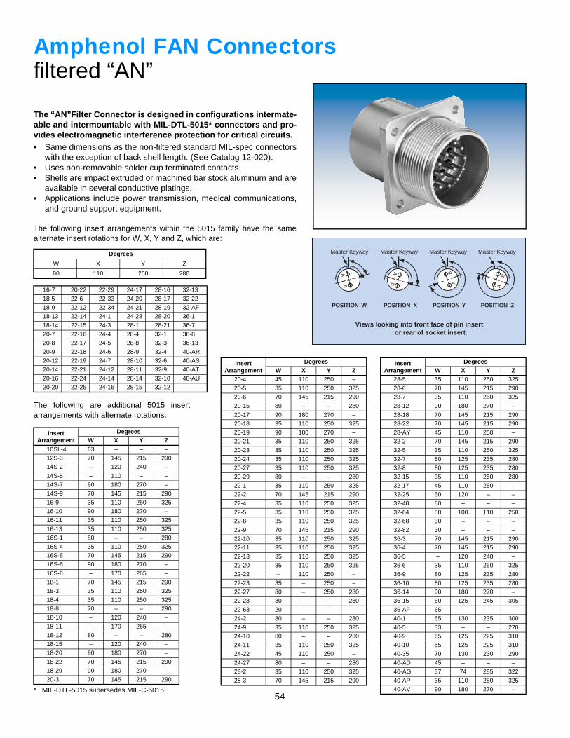
54
AB
Master Keyway
POSITION W
Master Keyway
POSITION X
Master Keyway
POSITION Y
Master Keyway
POSITION Z
Views looking into front face of pin insert or rear of socket insert.
AB A
B
BA
Amphenol FAN Connectorsfiltered “AN”
The “AN”Filter Connector is designed in configurations intermate-able and intermountable with MIL-DTL-5015* connectors and pro-vides electromagnetic interference protection for critical circuits.• Same dimensions as the non-filtered standard MIL-spec connectors
with the exception of back shell length. (See Catalog 12-020).• Uses non-removable solder cup terminated contacts.• Shells are impact extruded or machined bar stock aluminum and are
available in several conductive platings.• Applications include power transmission, medical communications,
and ground support equipment.
The following insert arrangements within the 5015 family have the samealternate insert rotations for W, X, Y and Z, which are:
Degrees
W X Y Z
80 110 250 280
16-7 20-22 22-29 24-17 28-16 32-13
18-5 22-6 22-33 24-20 28-17 32-22
18-9 22-12 22-34 24-21 28-19 32-AF
18-13 22-14 24-1 24-28 28-20 36-1
18-14 22-15 24-3 28-1 28-21 36-7
20-7 22-16 24-4 28-4 32-1 36-8
20-8 22-17 24-5 28-8 32-3 36-13
20-9 22-18 24-6 28-9 32-4 40-AR
20-12 22-19 24-7 28-10 32-6 40-AS
20-14 22-21 24-12 28-11 32-9 40-AT
20-16 22-24 24-14 28-14 32-10 40-AU
20-20 22-25 24-16 28-15 32-12
The following are additional 5015 insertarrangements with alternate rotations.
InsertArrangement
DegreesW X Y Z
10SL-4 63 – – –
12S-3 70 145 215 290
14S-2 – 120 240 –
14S-5 – 110 – –
14S-7 90 180 270 –
14S-9 70 145 215 290
16-9 35 110 250 325
16-10 90 180 270 –
16-11 35 110 250 325
16-13 35 110 250 325
16S-1 80 – – 280
16S-4 35 110 250 325
16S-5 70 145 215 290
16S-6 90 180 270 –
16S-8 – 170 265 –
18-1 70 145 215 290
18-3 35 110 250 325
18-4 35 110 250 325
18-8 70 – – 290
18-10 – 120 240 –
18-11 – 170 265 –
18-12 80 – – 280
18-15 – 120 240 –
18-20 90 180 270 –
18-22 70 145 215 290
18-29 90 180 270 –
20-3 70 145 215 290
20-4 45 110 250 –
20-5 35 110 250 325
20-6 70 145 215 290
20-15 80 – – 280
20-17 90 180 270 –
20-18 35 110 250 325
20-19 90 180 270 –
20-21 35 110 250 325
20-23 35 110 250 325
20-24 35 110 250 325
20-27 35 110 250 325
20-29 80 – – 280
22-1 35 110 250 325
22-2 70 145 215 290
22-4 35 110 250 325
22-5 35 110 250 325
22-8 35 110 250 325
22-9 70 145 215 290
22-10 35 110 250 325
22-11 35 110 250 325
22-13 35 110 250 325
22-20 35 110 250 325
22-22 – 110 250 –
22-23 35 – 250 –
22-27 80 – 250 280
22-28 80 – – 280
22-63 20 – – –
24-2 80 – – 280
24-9 35 110 250 325
24-10 80 – – 280
24-11 35 110 250 325
24-22 45 110 250 –
24-27 80 – – 280
28-2 35 110 250 325
28-3 70 145 215 290
InsertArrangement
DegreesW X Y Z
28-5 35 110 250 325
28-6 70 145 215 290
28-7 35 110 250 325
28-12 90 180 270 –
28-18 70 145 215 290
28-22 70 145 215 290
28-AY 45 110 250 –
32-2 70 145 215 290
32-5 35 110 250 325
32-7 80 125 235 280
32-8 80 125 235 280
32-15 35 110 250 280
32-17 45 110 250 –
32-25 60 120 – –
32-48 80 – – –
32-64 80 100 110 250
32-68 30 – – –
32-82 30 – – –
36-3 70 145 215 290
36-4 70 145 215 290
36-5 – 120 240 –
36-6 35 110 250 325
36-9 80 125 235 280
36-10 80 125 235 280
36-14 90 180 270 –
36-15 60 125 245 305
36-AF 65 – – –
40-1 65 130 235 300
40-5 33 – – 270
40-9 65 125 225 310
40-10 65 125 225 310
40-35 70 130 230 290
40-AD 45 – – –
40-AG 37 74 285 322
40-AP 35 110 250 325
40-AV 90 180 270 –
InsertArrangement
DegreesW X Y Z
* MIL-DTL-5015 supersedes MIL-C-5015.
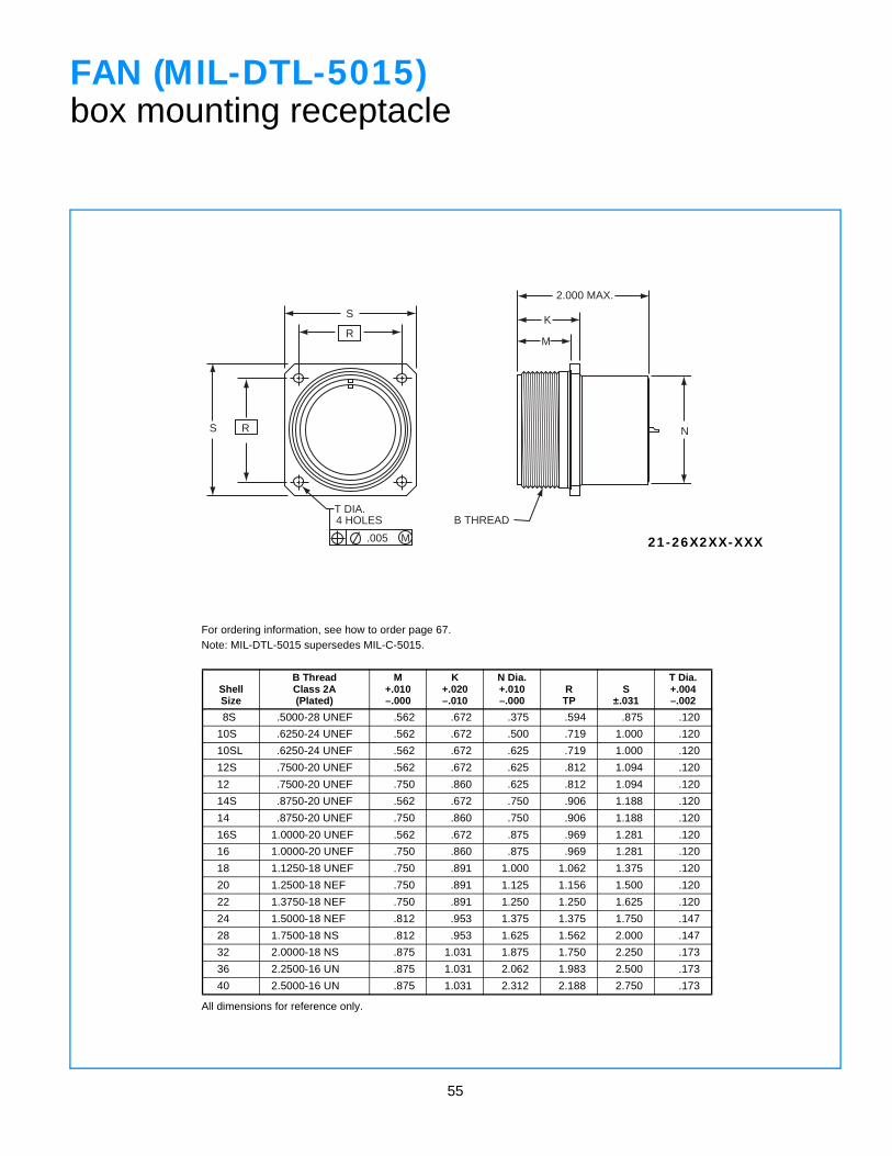
55
2.000 MAX.
K
M
N
B THREADT DIA.4 HOLES
.005 M
R
S
RS
FAN (MIL-DTL-5015)box mounting receptacle
ShellSize
B ThreadClass 2A(Plated)
M+.010–.000
K+.020–.010
N Dia.+.010–.000
RTP
S±.031
T Dia.+.004–.002
8S .5000-28 UNEF .562 .672 .375 .594 .875 .120
10S .6250-24 UNEF .562 .672 .500 .719 1.000 .120
10SL .6250-24 UNEF .562 .672 .625 .719 1.000 .120
12S .7500-20 UNEF .562 .672 .625 .812 1.094 .120
12 .7500-20 UNEF .750 .860 .625 .812 1.094 .120
14S .8750-20 UNEF .562 .672 .750 .906 1.188 .120
14 .8750-20 UNEF .750 .860 .750 .906 1.188 .120
16S 1.0000-20 UNEF .562 .672 .875 .969 1.281 .120
16 1.0000-20 UNEF .750 .860 .875 .969 1.281 .120
18 1.1250-18 UNEF .750 .891 1.000 1.062 1.375 .120
20 1.2500-18 NEF .750 .891 1.125 1.156 1.500 .120
22 1.3750-18 NEF .750 .891 1.250 1.250 1.625 .120
24 1.5000-18 NEF .812 .953 1.375 1.375 1.750 .147
28 1.7500-18 NS .812 .953 1.625 1.562 2.000 .147
32 2.0000-18 NS .875 1.031 1.875 1.750 2.250 .173
36 2.2500-16 UN .875 1.031 2.062 1.983 2.500 .173
40 2.5000-16 UN .875 1.031 2.312 2.188 2.750 .173
All dimensions for reference only.
21-26X2XX-XXX
For ordering information, see how to order page 67.Note: MIL-DTL-5015 supersedes MIL-C-5015.
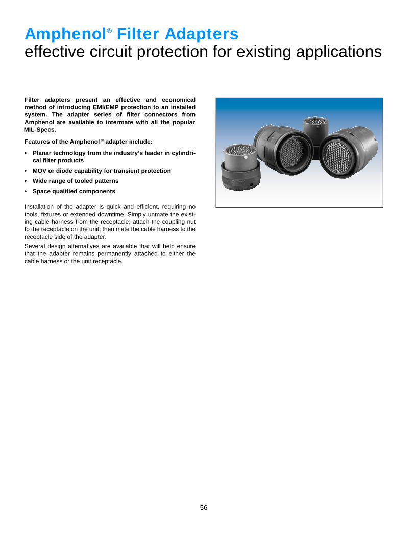
56
Amphenol Filter Adapterseffective circuit protection for existing applications
Filter adapters present an effective and economicalmethod of introducing EMI/EMP protection to an installedsystem. The adapter series of filter connectors fromAmphenol are available to intermate with all the popularMIL-Specs.
Features of the Amphenol ® adapter include:
• Planar technology from the industry’s leader in cylindri-cal filter products
• MOV or diode capability for transient protection
• Wide range of tooled patterns
• Space qualified components
Installation of the adapter is quick and efficient, requiring notools, fixtures or extended downtime. Simply unmate the exist-ing cable harness from the receptacle; attach the coupling nutto the receptacle on the unit; then mate the cable harness to thereceptacle side of the adapter.
Several design alternatives are available that will help ensurethat the adapter remains permanently attached to either thecable harness or the unit receptacle.
®
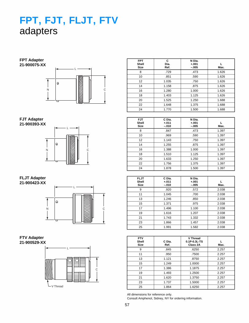
57
L
N C
L
N C
L
N C
L
V Thread
C
FPT, FJT, FLJT, FTVadapters
FPT Adapter21-900075-XX
FJT Adapter21-900393-XX
FLJT Adapter21-900423-XX
FTV Adapter21-900529-XX
FPTShellSize
CDia.Ref.
N Dia.+.001–.005
LMax.
8 .729 .473 1.626
10 .851 .590 1.626
12 1.035 .750 1.626
14 1.158 .875 1.626
16 1.280 1.000 1.626
18 1.403 1.125 1.626
20 1.525 1.250 1.688
22 1.648 1.375 1.688
24 1.770 1.500 1.688
FJTShellSize
C Dia.+.011–.010
N Dia.+.001–.005
LMax.
8 .847 .473 1.397
10 .969 .590 1.397
12 1.143 .750 1.397
14 1.255 .875 1.397
16 1.388 1.000 1.397
18 1.510 1.125 1.397
20 1.633 1.250 1.397
22 1.756 1.375 1.397
24 1.878 1.500 1.397
FLJTShellSize
C Dia.+.011–.010
N Dia.+.001–.005
LMax.
9 .920 .572 2.038
11 1.045 .700 2.038
13 1.246 .850 2.038
15 1.371 .975 2.038
17 1.496 1.100 2.038
19 1.616 1.207 2.038
21 1.743 1.332 2.038
23 1.866 1.457 2.038
25 1.991 1.582 2.038
All dimensions for reference only.Consult Amphenol, Sidney, NY for ordering information.
FTVShellSize
C Dia.Ref.
V Thread0.1P-0.3L-TS
Class 2AL
Max.
9 .845 .6250 2.257
11 .950 .7500 2.257
13 1.121 .8750 2.257
15 1.249 1.0000 2.257
17 1.386 1.1875 2.257
19 1.493 1.2500 2.257
21 1.620 1.3750 2.257
23 1.737 1.5000 2.257
25 1.864 1.6250 2.257
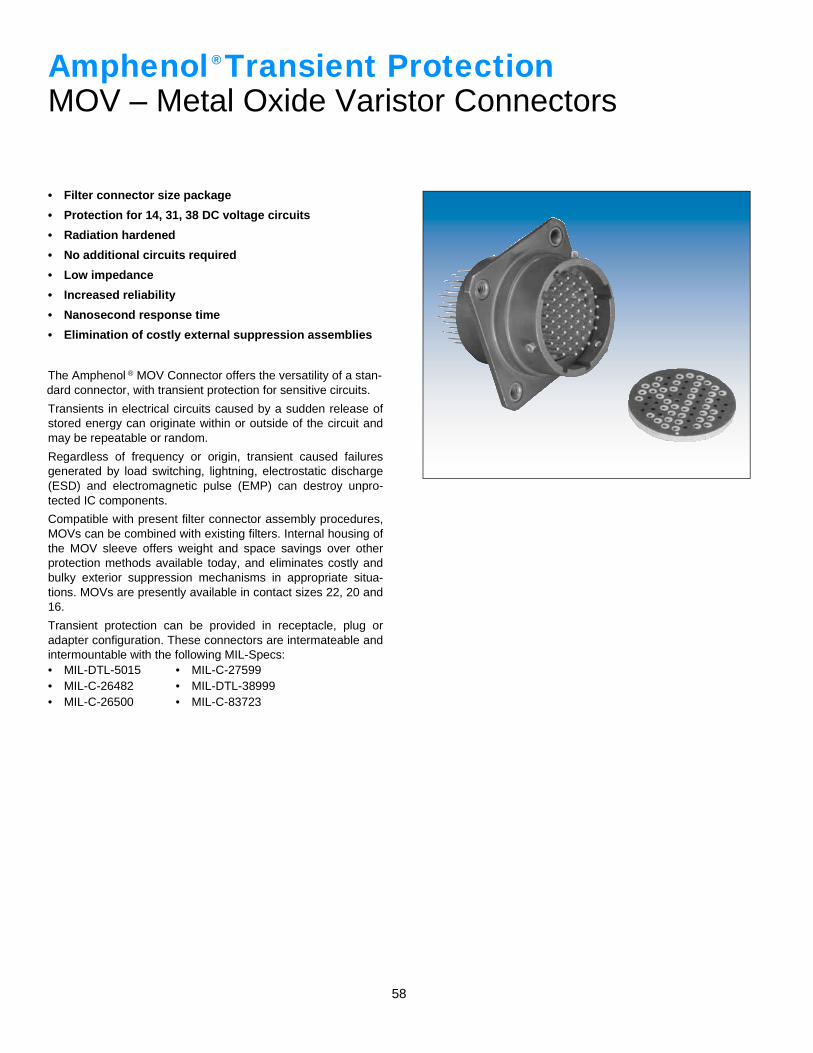
58
• Filter connector size package
• Protection for 14, 31, 38 DC voltage circuits
• Radiation hardened
• No additional circuits required
• Low impedance
• Increased reliability
• Nanosecond response time
• Elimination of costly external suppression assemblies
The Amphenol ® MOV Connector offers the versatility of a stan-dard connector, with transient protection for sensitive circuits.
Transients in electrical circuits caused by a sudden release ofstored energy can originate within or outside of the circuit andmay be repeatable or random.
Regardless of frequency or origin, transient caused failuresgenerated by load switching, lightning, electrostatic discharge(ESD) and electromagnetic pulse (EMP) can destroy unpro-tected IC components.
Compatible with present filter connector assembly procedures,MOVs can be combined with existing filters. Internal housing ofthe MOV sleeve offers weight and space savings over otherprotection methods available today, and eliminates costly andbulky exterior suppression mechanisms in appropriate situa-tions. MOVs are presently available in contact sizes 22, 20 and16.
Transient protection can be provided in receptacle, plug oradapter configuration. These connectors are intermateable andintermountable with the following MIL-Specs:• MIL-DTL-5015• MIL-C-26482• MIL-C-26500
• MIL-C-27599• MIL-DTL-38999• MIL-C-83723
Amphenol Transient ProtectionMOV – Metal Oxide Varistor Connectors
®
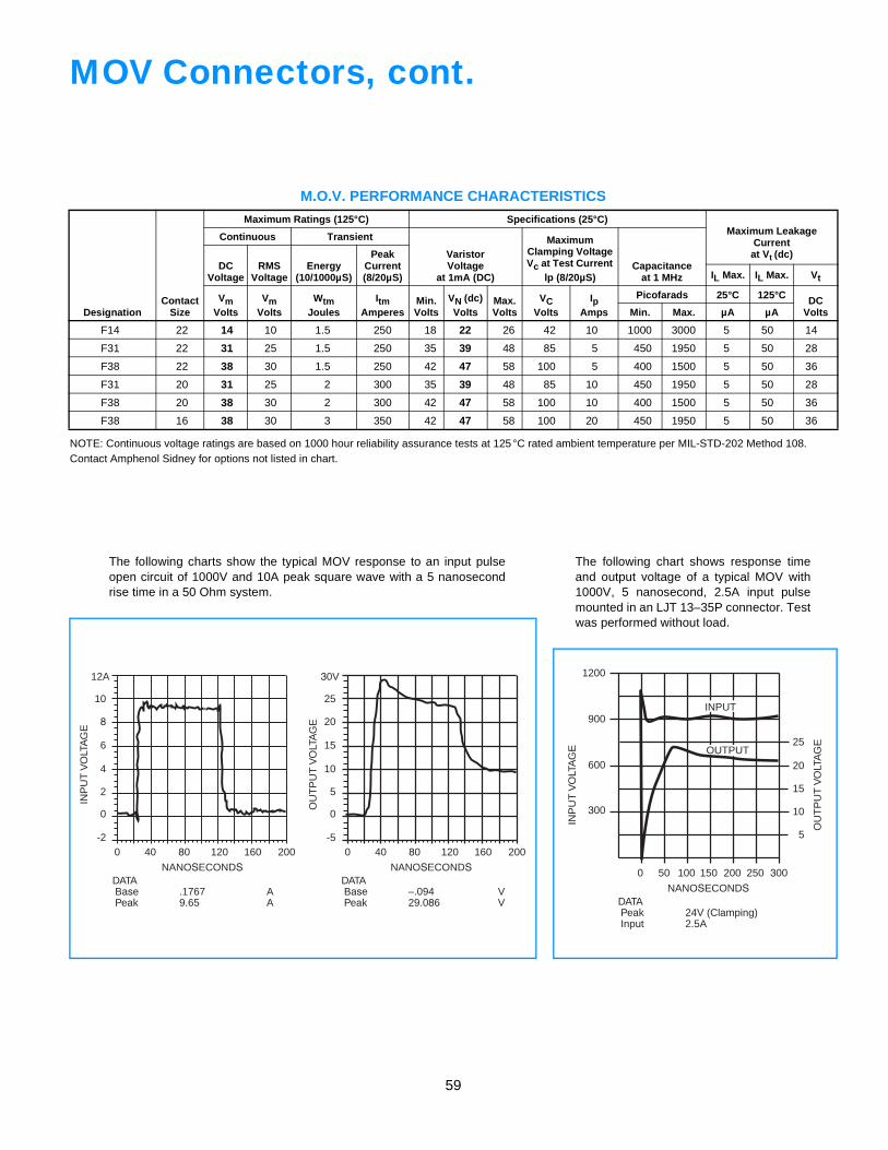
59
0 40 80 120 160 200 0 40 80 120 160 200-2
0
2
4
6
8
12A
10
NANOSECONDS
INP
UT
VO
LTA
GE
DATABase .1767 APeak 9.65 A
-5
0
5
10
15
20
30V
25
NANOSECONDS
OU
TP
UT
VO
LTA
GE
DATABase –.094 VPeak 29.086 V
NANOSECONDS
INP
UT
VO
LTA
GE
DATAPeak 24V (Clamping)Input 2.5A
300
600
900
1200
25
20
15
10
5
0 50 100 150 200 250 300
OU
TP
UT
VO
LTA
GE
OUTPUT
INPUT
MOV Connectors, cont.
NOTE: Continuous voltage ratings are based on 1000 hour reliability assurance tests at 125°C rated ambient temperature per MIL-STD-202 Method 108.Contact Amphenol Sidney for options not listed in chart.
M.O.V. PERFORMANCE CHARACTERISTICS
DesignationContact
Size
Maximum Ratings (125°C) Specifications (25°C)Maximum Leakage
Currentat Vt (dc)
Continuous Transient
VaristorVoltage
at 1mA (DC)
Maximum Clamping Voltage Vc at Test Current
lp (8/20µS)Capacitance
at 1 MHzDC
VoltageRMS
VoltageEnergy
(10/1000µS)
PeakCurrent(8/20µS) IL Max. IL Max. Vt
VmVolts
VmVolts
WtmJoules
ItmAmperes
Min.Volts
VN (dc)Volts
Max.Volts
VCVolts
IpAmps
Picofarads 25°C 125°C DC VoltsMin. Max. µA µA
F14 22 14 10 1.5 250 18 22 26 42 10 1000 3000 5 50 14
F31 22 31 25 1.5 250 35 39 48 85 5 450 1950 5 50 28
F38 22 38 30 1.5 250 42 47 58 100 5 400 1500 5 50 36
F31 20 31 25 2 300 35 39 48 85 10 450 1950 5 50 28
F38 20 38 30 2 300 42 47 58 100 10 400 1500 5 50 36
F38 16 38 30 3 350 42 47 58 100 20 450 1950 5 50 36
The following charts show the typical MOV response to an input pulseopen circuit of 1000V and 10A peak square wave with a 5 nanosecondrise time in a 50 Ohm system.
The following chart shows response timeand output voltage of a typical MOV with1000V, 5 nanosecond, 2.5A input pulsemounted in an LJT 13–35P connector. Testwas performed without load.
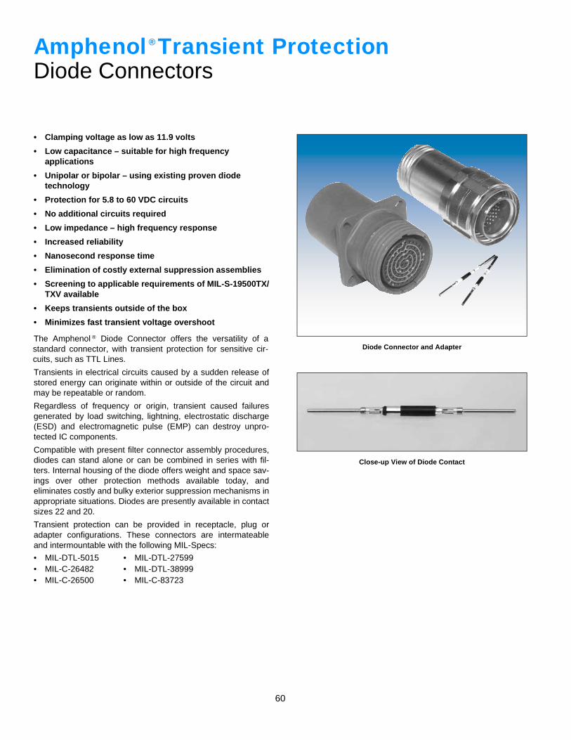
60
• Clamping voltage as low as 11.9 volts
• Low capacitance – suitable for high frequencyapplications
• Unipolar or bipolar – using existing proven diodetechnology
• Protection for 5.8 to 60 VDC circuits
• No additional circuits required
• Low impedance – high frequency response
• Increased reliability
• Nanosecond response time
• Elimination of costly external suppression assemblies
• Screening to applicable requirements of MIL-S-19500TX/TXV available
• Keeps transients outside of the box
• Minimizes fast transient voltage overshoot
The Amphenol ® Diode Connector offers the versatility of astandard connector, with transient protection for sensitive cir-cuits, such as TTL Lines.
Transients in electrical circuits caused by a sudden release ofstored energy can originate within or outside of the circuit andmay be repeatable or random.
Regardless of frequency or origin, transient caused failuresgenerated by load switching, lightning, electrostatic discharge(ESD) and electromagnetic pulse (EMP) can destroy unpro-tected IC components.
Compatible with present filter connector assembly procedures,diodes can stand alone or can be combined in series with fil-ters. Internal housing of the diode offers weight and space sav-ings over other protection methods available today, andeliminates costly and bulky exterior suppression mechanisms inappropriate situations. Diodes are presently available in contactsizes 22 and 20.
Transient protection can be provided in receptacle, plug oradapter configurations. These connectors are intermateableand intermountable with the following MIL-Specs:
• MIL-DTL-5015• MIL-C-26482• MIL-C-26500
• MIL-DTL-27599• MIL-DTL-38999• MIL-C-83723
Amphenol Transient ProtectionDiode Connectors
®
Diode Connector and Adapter
Close-up View of Diode Contact
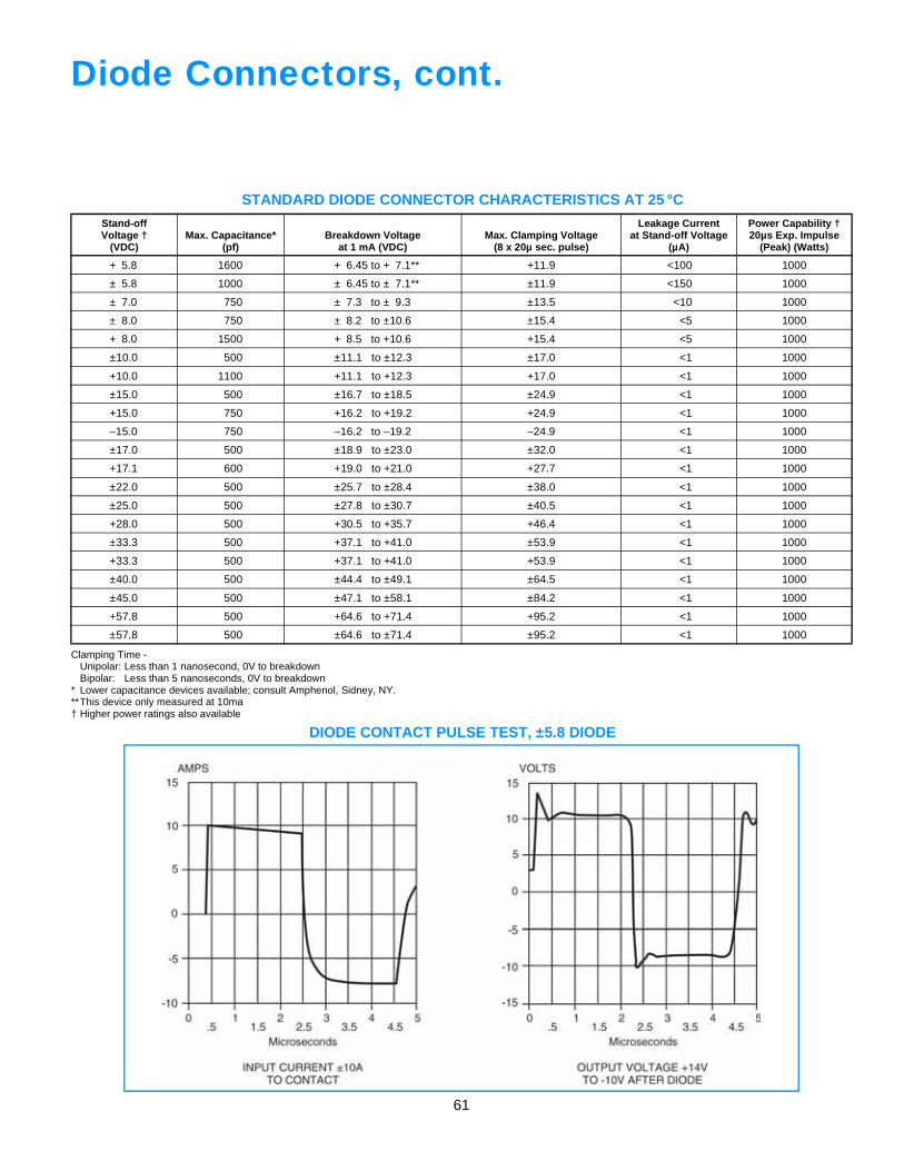
61
Diode Connectors, cont.
Clamping Time -Unipolar: Less than 1 nanosecond, 0V to breakdownBipolar: Less than 5 nanoseconds, 0V to breakdown
* Lower capacitance devices available; consult Amphenol, Sidney, NY.**This device only measured at 10ma† Higher power ratings also available
STANDARD DIODE CONNECTOR CHARACTERISTICS AT 25 °C
Stand-offVoltage †
(VDC)Max. Capacitance*
(pf)Breakdown Voltage
at 1 mA (VDC)Max. Clamping Voltage
(8 x 20µ sec. pulse)
Leakage Currentat Stand-off Voltage
(µA)
Power Capability †20µs Exp. Impulse
(Peak) (Watts)
+ 5.8 1600 + 6.45 to + 7.1** +11.9 <100 1000
± 5.8 1000 ± 6.45 to ± 7.1** ±11.9 <150 1000
± 7.0 750 ± 7.3 to ± 9.3 ±13.5 <10 1000
± 8.0 750 ± 8.2 to ±10.6 ±15.4 <5 1000
+ 8.0 1500 + 8.5 to +10.6 +15.4 <5 1000
±10.0 500 ±11.1 to ±12.3 ±17.0 <1 1000
+10.0 1100 +11.1 to +12.3 +17.0 <1 1000
±15.0 500 ±16.7 to ±18.5 ±24.9 <1 1000
+15.0 750 +16.2 to +19.2 +24.9 <1 1000
–15.0 750 –16.2 to –19.2 –24.9 <1 1000
±17.0 500 ±18.9 to ±23.0 ±32.0 <1 1000
+17.1 600 +19.0 to +21.0 +27.7 <1 1000
±22.0 500 ±25.7 to ±28.4 ±38.0 <1 1000
±25.0 500 ±27.8 to ±30.7 ±40.5 <1 1000
+28.0 500 +30.5 to +35.7 +46.4 <1 1000
±33.3 500 +37.1 to +41.0 ±53.9 <1 1000
+33.3 500 +37.1 to +41.0 +53.9 <1 1000
±40.0 500 ±44.4 to ±49.1 ±64.5 <1 1000
±45.0 500 ±47.1 to ±58.1 ±84.2 <1 1000
+57.8 500 +64.6 to +71.4 +95.2 <1 1000
±57.8 500 ±64.6 to ±71.4 ±95.2 <1 1000
DIODE CONTACT PULSE TEST, ±5.8 DIODE
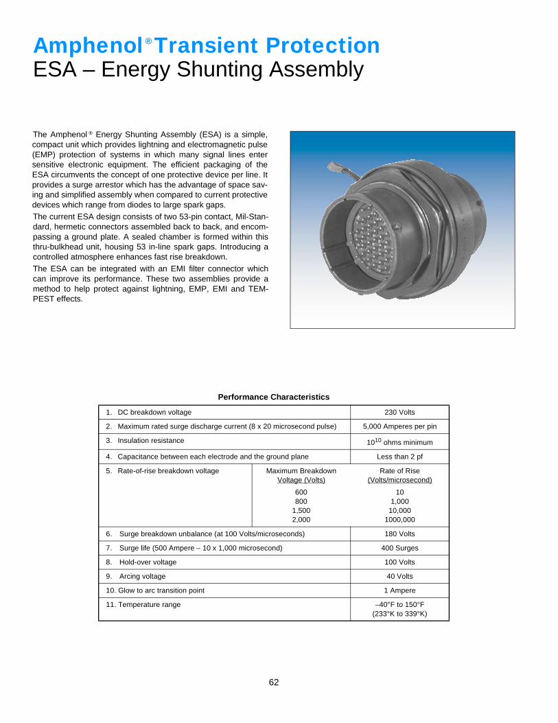
62
The Amphenol ® Energy Shunting Assembly (ESA) is a simple,compact unit which provides lightning and electromagnetic pulse(EMP) protection of systems in which many signal lines entersensitive electronic equipment. The efficient packaging of theESA circumvents the concept of one protective device per line. Itprovides a surge arrestor which has the advantage of space sav-ing and simplified assembly when compared to current protectivedevices which range from diodes to large spark gaps.The current ESA design consists of two 53-pin contact, Mil-Stan-dard, hermetic connectors assembled back to back, and encom-passing a ground plate. A sealed chamber is formed within thisthru-bulkhead unit, housing 53 in-line spark gaps. Introducing acontrolled atmosphere enhances fast rise breakdown.The ESA can be integrated with an EMI filter connector whichcan improve its performance. These two assemblies provide amethod to help protect against lightning, EMP, EMI and TEM-PEST effects.
Performance Characteristics
1. DC breakdown voltage 230 Volts
2. Maximum rated surge discharge current (8 x 20 microsecond pulse) 5,000 Amperes per pin
3. Insulation resistance 1010 ohms minimum
4. Capacitance between each electrode and the ground plane Less than 2 pf
5. Rate-of-rise breakdown voltage Maximum BreakdownVoltage (Volts)
Rate of Rise(Volts/microsecond)
600800
1,5002,000
101,000
10,0001000,000
6. Surge breakdown unbalance (at 100 Volts/microseconds) 180 Volts
7. Surge life (500 Ampere – 10 x 1,000 microsecond) 400 Surges
8. Hold-over voltage 100 Volts
9. Arcing voltage 40 Volts
10. Glow to arc transition point 1 Ampere
11. Temperature range –40°F to 150°F(233°K to 339°K)
Amphenol Transient ProtectionESA – Energy Shunting Assembly
®
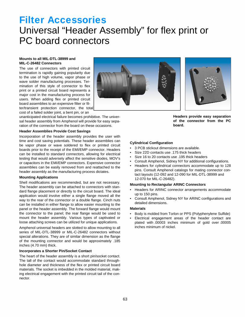
63
Filter AccessoriesUniversal “Header Assembly” for flex print orPC board connectors
Mounts to all MIL-DTL-38999 andMIL-C-26482 ConnectorsThe use of connectors with printed circuittermination is rapidly gaining popularity dueto the use of high volume, vapor phase orwave solder manufacturing processes. Ter-mination of this style of connector to flexprint or a printed circuit board represents amajor cost in the manufacturing process forusers. When adding flex or printed circuitboard assemblies to an expensive filter or fil-ter/transient protection connector, the totalcost of a failed solder joint, a bent pin, or anunanticipated electrical failure becomes prohibitive. The univer-sal header assembly from Amphenol will provide for easy sepa-ration of the connector from the board on these occasions.
Header Assemblies Provide Cost SavingsIncorporation of the header assembly provides the user withtime and cost saving potentials. These header assemblies canbe vapor phase or wave soldered to flex or printed circuitboards prior to the receipt of the EMI/EMP connector. Headerscan be installed to standard connectors, allowing for electricaltesting that would adversely affect the sensitive diodes, MOV’sor capacitors in the EMI/EMP connectors. Expensive connectorassemblies can be easily removed from and reattached to theheader assembly as the manufacturing process dictates.
Mounting ApplicationsShell modifications are recommended, but are not necessary.The header assembly can be attached to connectors with stan-dard flange placement or directly to the circuit board. The idealapplication would involve either a single flange moved all theway to the rear of the connector or a double flange. Cinch nutscan be installed in either flange to allow easier mounting to thepanel or the header assembly. The forward flange would mountthe connector to the panel; the rear flange would be used tomount the header assembly. Various types of captivated orloose attaching screws can be utilized for unique applications.
Amphenol universal headers are slotted to allow mounting to allseries of MIL-DTL-38999 or MIL-C-26482 connectors withoutspecial alterations. They are of similar dimension as the flangeof the mounting connector and would be approximately .185inches (4.70 mm) thick.
Incorporates a Shorter Pin/Socket ContactThe heart of the header assembly is a short pin/socket contact.The tall of the contact would accommodate standard through-hole diameter and thickness of the flex or printed circuit boardmaterials. The socket is imbedded in the molded material, mak-ing electrical engagement with the printed circuit tail of the con-nector.
Headers provide easy separationof the connector from the PCboard.
Cylindrical Configuration• 3 PCB stickout dimensions are available.• Size 22D contacts use .175 thick headers• Size 16 to 20 contacts use .195 thick headers• Consult Amphenol, Sidney NY for additional configurations.• Headers for cylindrical connectors accommodate up to 128
pins. Consult Amphenol catalogs for mating connector con-tact layouts (12-092 and 12-090 for MIL-DTL-38999 and12-070 for MIL-C-26482).
Mounting to Rectangular ARINC Connectors• Headers for ARINC connector arrangements accommodate
up to 150 pins.• Consult Amphenol, Sidney NY for ARINC configurations and
detailed dimensions.
Materials• Body is molded from Torlon or PPS (Polyphenylene Sulfide)• Electrical engagement areas of the header contact are
plated with .00003 inches minimum of gold over .00005inches minimum of nickel.
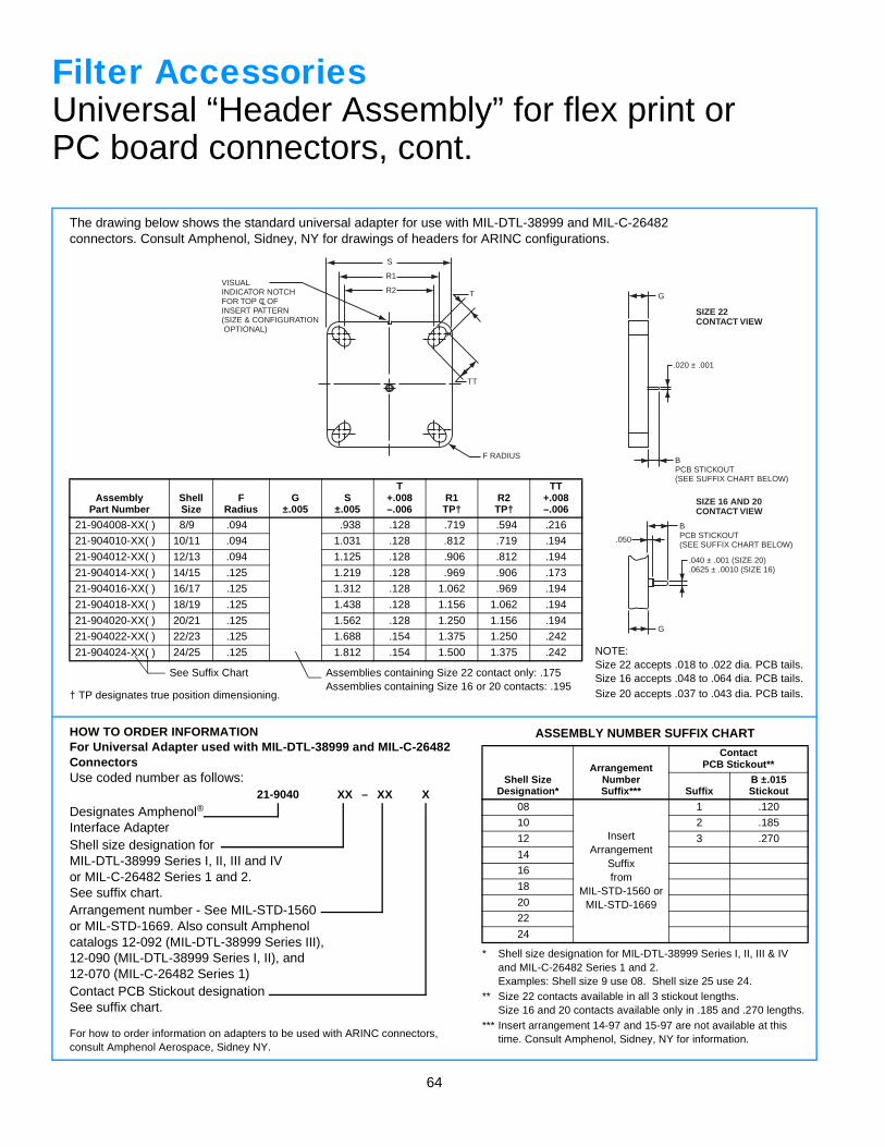
64
R2
R1
S
T
TT
VISUALINDICATOR NOTCHFOR TOP C OFINSERT PATTERN(SIZE & CONFIGURATIONOPTIONAL)
L
F RADIUS BPCB STICKOUT(SEE SUFFIX CHART BELOW)
G
.020 ± .001
.040 ± .001 (SIZE 20)
.0625 ± .0010 (SIZE 16)
BPCB STICKOUT(SEE SUFFIX CHART BELOW)
.050
G
SIZE 22CONTACT VIEW
SIZE 16 AND 20CONTACT VIEW
Filter AccessoriesUniversal “Header Assembly” for flex print orPC board connectors, cont.
The drawing below shows the standard universal adapter for use with MIL-DTL-38999 and MIL-C-26482 connectors. Consult Amphenol, Sidney, NY for drawings of headers for ARINC configurations.
† TP designates true position dimensioning.
AssemblyPart Number
ShellSize
FRadius
G±.005
S±.005
T+.008–.006
R1TP†
R2TP†
TT+.008–.006
21-904008-XX( ) 8/9 .094 .938 .128 .719 .594 .216
21-904010-XX( ) 10/11 .094 1.031 .128 .812 .719 .194
21-904012-XX( ) 12/13 .094 1.125 .128 .906 .812 .194
21-904014-XX( ) 14/15 .125 1.219 .128 .969 .906 .173
21-904016-XX( ) 16/17 .125 1.312 .128 1.062 .969 .194
21-904018-XX( ) 18/19 .125 1.438 .128 1.156 1.062 .194
21-904020-XX( ) 20/21 .125 1.562 .128 1.250 1.156 .194
21-904022-XX( ) 22/23 .125 1.688 .154 1.375 1.250 .242
21-904024-XX( ) 24/25 .125 1.812 .154 1.500 1.375 .242
HOW TO ORDER INFORMATIONFor Universal Adapter used with MIL-DTL-38999 and MIL-C-26482ConnectorsUse coded number as follows:
21-9040 XX – XX X
Designates Amphenol®
Interface AdapterShell size designation forMIL-DTL-38999 Series I, II, III and IVor MIL-C-26482 Series 1 and 2.See suffix chart.Arrangement number - See MIL-STD-1560or MIL-STD-1669. Also consult Amphenolcatalogs 12-092 (MIL-DTL-38999 Series III),12-090 (MIL-DTL-38999 Series I, II), and12-070 (MIL-C-26482 Series 1)Contact PCB Stickout designationSee suffix chart.
For how to order information on adapters to be used with ARINC connectors,consult Amphenol Aerospace, Sidney NY.
* Shell size designation for MIL-DTL-38999 Series I, II, III & IVand MIL-C-26482 Series 1 and 2.Examples: Shell size 9 use 08. Shell size 25 use 24.
** Size 22 contacts available in all 3 stickout lengths.Size 16 and 20 contacts available only in .185 and .270 lengths.
*** Insert arrangement 14-97 and 15-97 are not available at thistime. Consult Amphenol, Sidney, NY for information.
ASSEMBLY NUMBER SUFFIX CHART
Shell SizeDesignation*
ArrangementNumberSuffix***
ContactPCB Stickout**
SuffixB ±.015Stickout
08
InsertArrangement
Suffixfrom
MIL-STD-1560 or MIL-STD-1669
1 .120
10 2 .185
12 3 .270
14
16
18
20
22
24
NOTE:Size 22 accepts .018 to .022 dia. PCB tails.Size 16 accepts .048 to .064 dia. PCB tails.Size 20 accepts .037 to .043 dia. PCB tails.
Assemblies containing Size 22 contact only: .175Assemblies containing Size 16 or 20 contacts: .195
See Suffix Chart
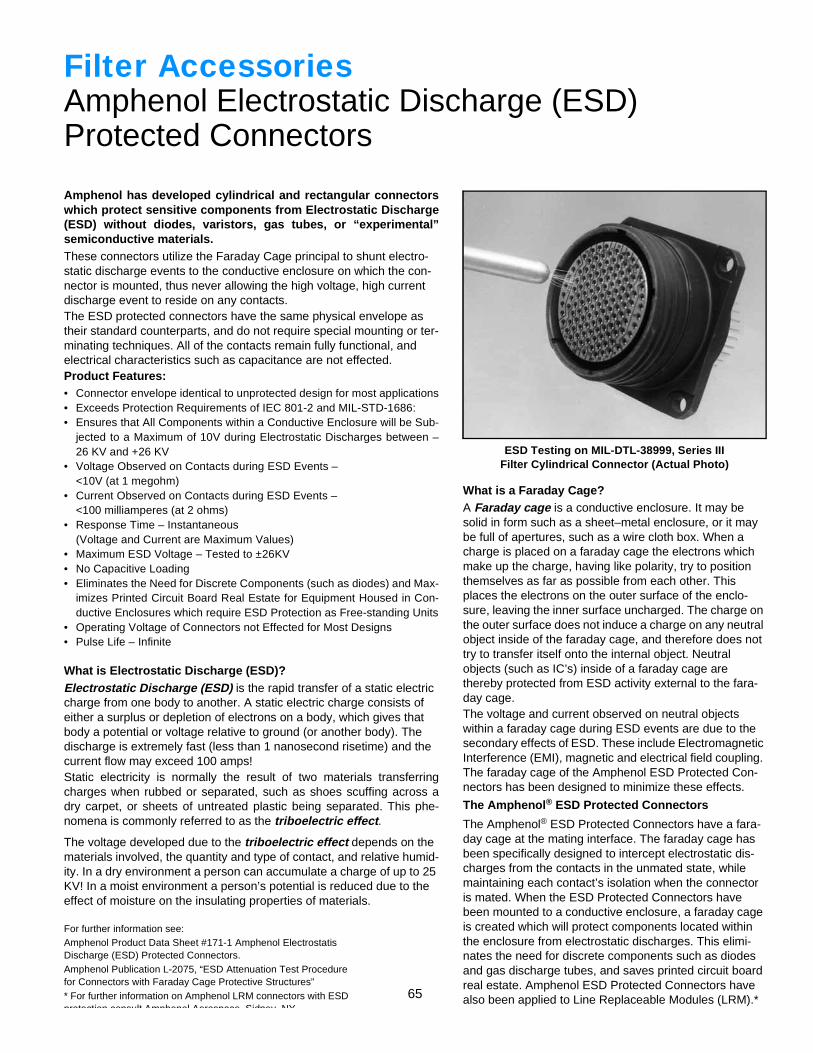
65
Filter AccessoriesAmphenol Electrostatic Discharge (ESD)Protected Connectors
Amphenol has developed cylindrical and rectangular connectorswhich protect sensitive components from Electrostatic Discharge(ESD) without diodes, varistors, gas tubes, or “experimental”semiconductive materials.These connectors utilize the Faraday Cage principal to shunt electro-static discharge events to the conductive enclosure on which the con-nector is mounted, thus never allowing the high voltage, high current discharge event to reside on any contacts.The ESD protected connectors have the same physical envelope as their standard counterparts, and do not require special mounting or ter-minating techniques. All of the contacts remain fully functional, and electrical characteristics such as capacitance are not effected.Product Features:• Connector envelope identical to unprotected design for most applications• Exceeds Protection Requirements of IEC 801-2 and MIL-STD-1686:• Ensures that All Components within a Conductive Enclosure will be Sub-
jected to a Maximum of 10V during Electrostatic Discharges between –26 KV and +26 KV
• Voltage Observed on Contacts during ESD Events –<10V (at 1 megohm)
• Current Observed on Contacts during ESD Events –<100 milliamperes (at 2 ohms)
• Response Time – Instantaneous(Voltage and Current are Maximum Values)
• Maximum ESD Voltage – Tested to ±26KV• No Capacitive Loading• Eliminates the Need for Discrete Components (such as diodes) and Max-
imizes Printed Circuit Board Real Estate for Equipment Housed in Con-ductive Enclosures which require ESD Protection as Free-standing Units
• Operating Voltage of Connectors not Effected for Most Designs• Pulse Life – Infinite
What is Electrostatic Discharge (ESD)?Electrostatic Discharge (ESD) is the rapid transfer of a static electric charge from one body to another. A static electric charge consists of either a surplus or depletion of electrons on a body, which gives that body a potential or voltage relative to ground (or another body). The discharge is extremely fast (less than 1 nanosecond risetime) and the current flow may exceed 100 amps!Static electricity is normally the result of two materials transferringcharges when rubbed or separated, such as shoes scuffing across adry carpet, or sheets of untreated plastic being separated. This phe-nomena is commonly referred to as the triboelectric effect.
The voltage developed due to the triboelectric effect depends on the materials involved, the quantity and type of contact, and relative humid-ity. In a dry environment a person can accumulate a charge of up to 25 KV! In a moist environment a person’s potential is reduced due to the effect of moisture on the insulating properties of materials.
What is a Faraday Cage?A Faraday cage is a conductive enclosure. It may be solid in form such as a sheet–metal enclosure, or it may be full of apertures, such as a wire cloth box. When a charge is placed on a faraday cage the electrons which make up the charge, having like polarity, try to position themselves as far as possible from each other. This places the electrons on the outer surface of the enclo-sure, leaving the inner surface uncharged. The charge on the outer surface does not induce a charge on any neutral object inside of the faraday cage, and therefore does not try to transfer itself onto the internal object. Neutral objects (such as IC’s) inside of a faraday cage are thereby protected from ESD activity external to the fara-day cage.The voltage and current observed on neutral objects within a faraday cage during ESD events are due to the secondary effects of ESD. These include Electromagnetic Interference (EMI), magnetic and electrical field coupling. The faraday cage of the Amphenol ESD Protected Con-nectors has been designed to minimize these effects.
The Amphenol® ESD Protected Connectors
The Amphenol® ESD Protected Connectors have a fara-day cage at the mating interface. The faraday cage has been specifically designed to intercept electrostatic dis-charges from the contacts in the unmated state, while maintaining each contact’s isolation when the connector is mated. When the ESD Protected Connectors have been mounted to a conductive enclosure, a faraday cage is created which will protect components located within the enclosure from electrostatic discharges. This elimi-nates the need for discrete components such as diodes and gas discharge tubes, and saves printed circuit board real estate. Amphenol ESD Protected Connectors have also been applied to Line Replaceable Modules (LRM).*
ESD Testing on MIL-DTL-38999, Series IIIFilter Cylindrical Connector (Actual Photo)
For further information see:Amphenol Product Data Sheet #171-1 Amphenol Electrostatis Discharge (ESD) Protected Connectors.Amphenol Publication L-2075, “ESD Attenuation Test Procedure for Connectors with Faraday Cage Protective Structures”* For further information on Amphenol LRM connectors with ESD protection consult Amphenol Aerospace Sidney NY
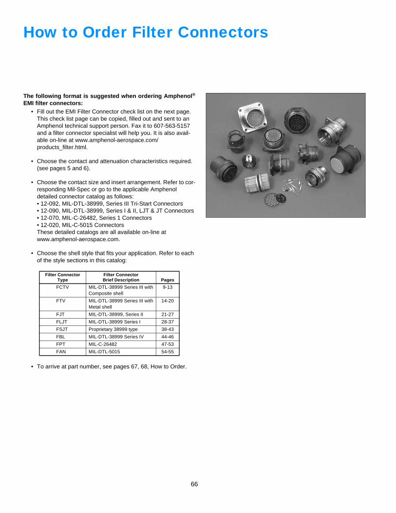
66
How to Order Filter Connectors
The following format is suggested when ordering Amphenol®
EMI filter connectors:• Fill out the EMI Filter Connector check list on the next page.
This check list page can be copied, filled out and sent to an Amphenol technical support person. Fax it to 607-563-5157 and a filter connector specialist will help you. It is also avail-able on-line at www.amphenol-aerospace.com/products_filter.html.
• Choose the contact and attenuation characteristics required. (see pages 5 and 6).
• Choose the contact size and insert arrangement. Refer to cor-responding Mil-Spec or go to the applicable Amphenol detailed connector catalog as follows:• 12-092, MIL-DTL-38999, Series III Tri-Start Connectors• 12-090, MIL-DTL-38999, Series I & II, LJT & JT Connectors• 12-070, MIL-C-26482, Series 1 Connectors• 12-020, MIL-C-5015 ConnectorsThese detailed catalogs are all available on-line at www.amphenol-aerospace.com.
• Choose the shell style that fits your application. Refer to each of the style sections in this catalog:
• To arrive at part number, see pages 67, 68, How to Order.
Filter Connector Type
Filter ConnectorBrief Description Pages
FCTV MIL-DTL-38999 Series III with Composite shell
9-13
FTV MIL-DTL-38999 Series III with Metal shell
14-20
FJT MIL-DTL-38999, Series II 21-27
FLJT MIL-DTL-38999 Series I 28-37
FSJT Proprietary 38999 type 38-43
FBL MIL-DTL-38999 Series IV 44-46
FPT MIL-C-26482 47-53
FAN MIL-DTL-5015 54-55
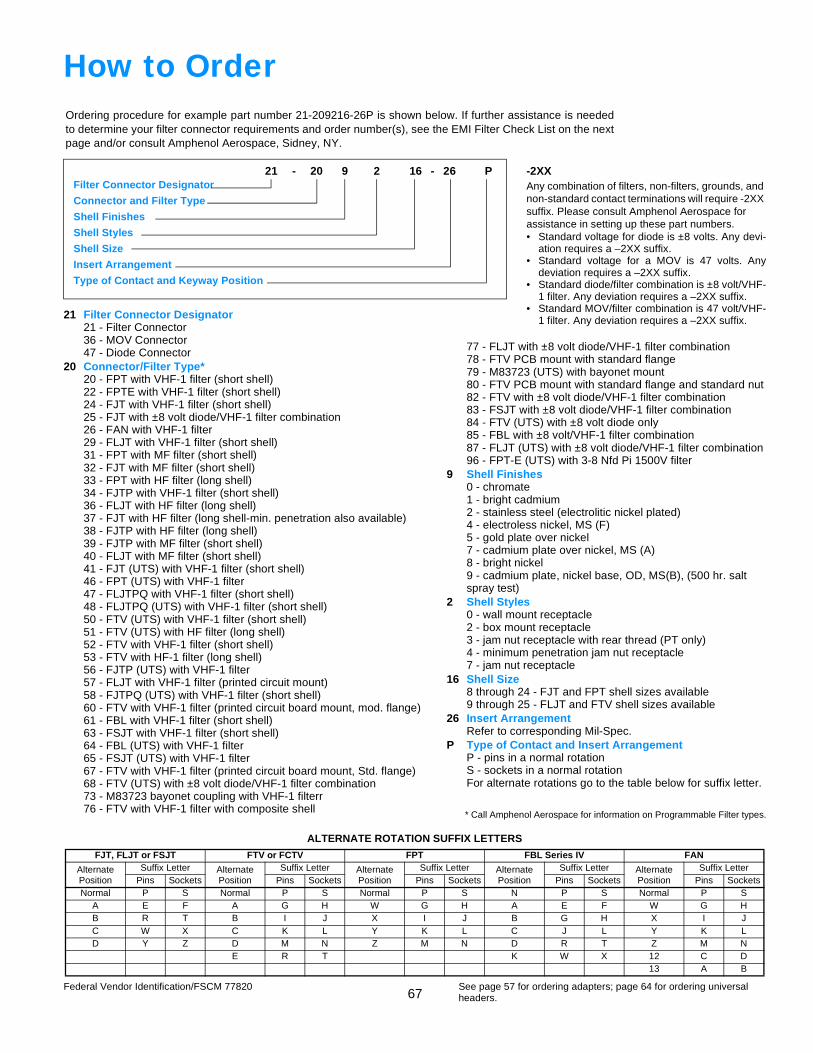
67
Ordering procedure for example part number 21-209216-26P is shown below. If further assistance is neededto determine your filter connector requirements and order number(s), see the EMI Filter Check List on the nextpage and/or consult Amphenol Aerospace, Sidney, NY.
21 - 20 9 2 16 - 26 PFilter Connector Designator
Connector and Filter Type
Shell Finishes
Shell Styles
Shell Size
Insert Arrangement
Type of Contact and Keyway Position
How to Order
21 Filter Connector Designator21 - Filter Connector36 - MOV Connector47 - Diode Connector
20 Connector/Filter Type*20 - FPT with VHF-1 filter (short shell)22 - FPTE with VHF-1 filter (short shell)24 - FJT with VHF-1 filter (short shell)25 - FJT with ±8 volt diode/VHF-1 filter combination26 - FAN with VHF-1 filter29 - FLJT with VHF-1 filter (short shell)31 - FPT with MF filter (short shell)32 - FJT with MF filter (short shell)33 - FPT with HF filter (long shell)34 - FJTP with VHF-1 filter (short shell)36 - FLJT with HF filter (long shell)37 - FJT with HF filter (long shell-min. penetration also available)38 - FJTP with HF filter (long shell)39 - FJTP with MF filter (short shell)40 - FLJT with MF filter (short shell)41 - FJT (UTS) with VHF-1 filter (short shell)46 - FPT (UTS) with VHF-1 filter47 - FLJTPQ with VHF-1 filter (short shell)48 - FLJTPQ (UTS) with VHF-1 filter (short shell)50 - FTV (UTS) with VHF-1 filter (short shell)51 - FTV (UTS) with HF filter (long shell)52 - FTV with VHF-1 filter (short shell)53 - FTV with HF-1 filter (long shell)56 - FJTP (UTS) with VHF-1 filter57 - FLJT with VHF-1 filter (printed circuit mount)58 - FJTPQ (UTS) with VHF-1 filter (short shell)60 - FTV with VHF-1 filter (printed circuit board mount, mod. flange)61 - FBL with VHF-1 filter (short shell)63 - FSJT with VHF-1 filter (short shell)64 - FBL (UTS) with VHF-1 filter65 - FSJT (UTS) with VHF-1 filter67 - FTV with VHF-1 filter (printed circuit board mount, Std. flange)68 - FTV (UTS) with ±8 volt diode/VHF-1 filter combination73 - M83723 bayonet coupling with VHF-1 filterr76 - FTV with VHF-1 filter with composite shell
-2XXAny combination of filters, non-filters, grounds, and non-standard contact terminations will require -2XX suffix. Please consult Amphenol Aerospace for assistance in setting up these part numbers.• Standard voltage for diode is ±8 volts. Any devi-
ation requires a –2XX suffix.• Standard voltage for a MOV is 47 volts. Any
deviation requires a –2XX suffix.• Standard diode/filter combination is ±8 volt/VHF-
1 filter. Any deviation requires a –2XX suffix.• Standard MOV/filter combination is 47 volt/VHF-
1 filter. Any deviation requires a –2XX suffix.
77 - FLJT with ±8 volt diode/VHF-1 filter combination78 - FTV PCB mount with standard flange79 - M83723 (UTS) with bayonet mount80 - FTV PCB mount with standard flange and standard nut82 - FTV with ±8 volt diode/VHF-1 filter combination83 - FSJT with ±8 volt diode/VHF-1 filter combination84 - FTV (UTS) with ±8 volt diode only85 - FBL with ±8 volt/VHF-1 filter combination87 - FLJT (UTS) with ±8 volt diode/VHF-1 filter combination96 - FPT-E (UTS) with 3-8 Nfd Pi 1500V filter
9 Shell Finishes0 - chromate1 - bright cadmium2 - stainless steel (electrolitic nickel plated)4 - electroless nickel, MS (F)5 - gold plate over nickel7 - cadmium plate over nickel, MS (A)8 - bright nickel9 - cadmium plate, nickel base, OD, MS(B), (500 hr. saltspray test)
2 Shell Styles0 - wall mount receptacle2 - box mount receptacle3 - jam nut receptacle with rear thread (PT only)4 - minimum penetration jam nut receptacle7 - jam nut receptacle
16 Shell Size8 through 24 - FJT and FPT shell sizes available9 through 25 - FLJT and FTV shell sizes available
26 Insert ArrangementRefer to corresponding Mil-Spec.
P Type of Contact and Insert ArrangementP - pins in a normal rotationS - sockets in a normal rotationFor alternate rotations go to the table below for suffix letter.
ALTERNATE ROTATION SUFFIX LETTERS
FJT, FLJT or FSJT FTV or FCTV FPT FBL Series IV FAN
AlternatePosition
Suffix Letter AlternatePosition
Suffix Letter AlternatePosition
Suffix Letter AlternatePosition
Suffix Letter AlternatePosition
Suffix LetterPins Sockets Pins Sockets Pins Sockets Pins Sockets Pins Sockets
Normal P S Normal P S Normal P S N P S Normal P SA E F A G H W G H A E F W G HB R T B I J X I J B G H X I JC W X C K L Y K L C J L Y K LD Y Z D M N Z M N D R T Z M N
E R T K W X 12 C D13 A B
See page 57 for ordering adapters; page 64 for ordering universal headers.
Federal Vendor Identification/FSCM 77820
* Call Amphenol Aerospace for information on Programmable Filter types.
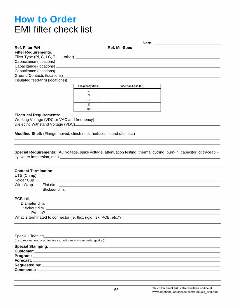
68
How to OrderEMI filter check list
DateRef. Filter P/N Ref. Mil-SpecFilter Requirements:Filter Type (Pi, C, LC, T, LL, other)Capacitance (locations)Capacitance (locations)Capacitance (locations)Ground Contacts (locations)Insulated feed-thru (locations))
Electrical Requirements:Working Voltage (VDC or VAC and frequency)Dielectric Withstand Voltage (VDC)
Modified Shell: (Flange moved, clinch nuts, heilicoils, stand offs, etc.)
Special Requirements: (AC voltage, spike voltage, attenuation testing, thermal cycling, burn-in, capacitor lot traceabil-ity, water immersion, etc.)
Contact Termination:UTS (Crimp)Solder CupWire Wrap Flat dim.
Stickout dim.
PCB tail:Diameter dim.Stickout dim.
Pre-tin?What is terminated to connector (ie. flex, rigid flex, PCB, etc.)?
Special Cleaning(if so, recommend a protective cap with an environmental gasket)
Special Stamping:Customer:Program:Forecast:Requested by:Comments:
Frequency (MHz) Insertion Loss (dB)
1
3
10
30
100
This Filter check list is also available on-line atwww.amphenol-aerospace.com/products_filter.html.
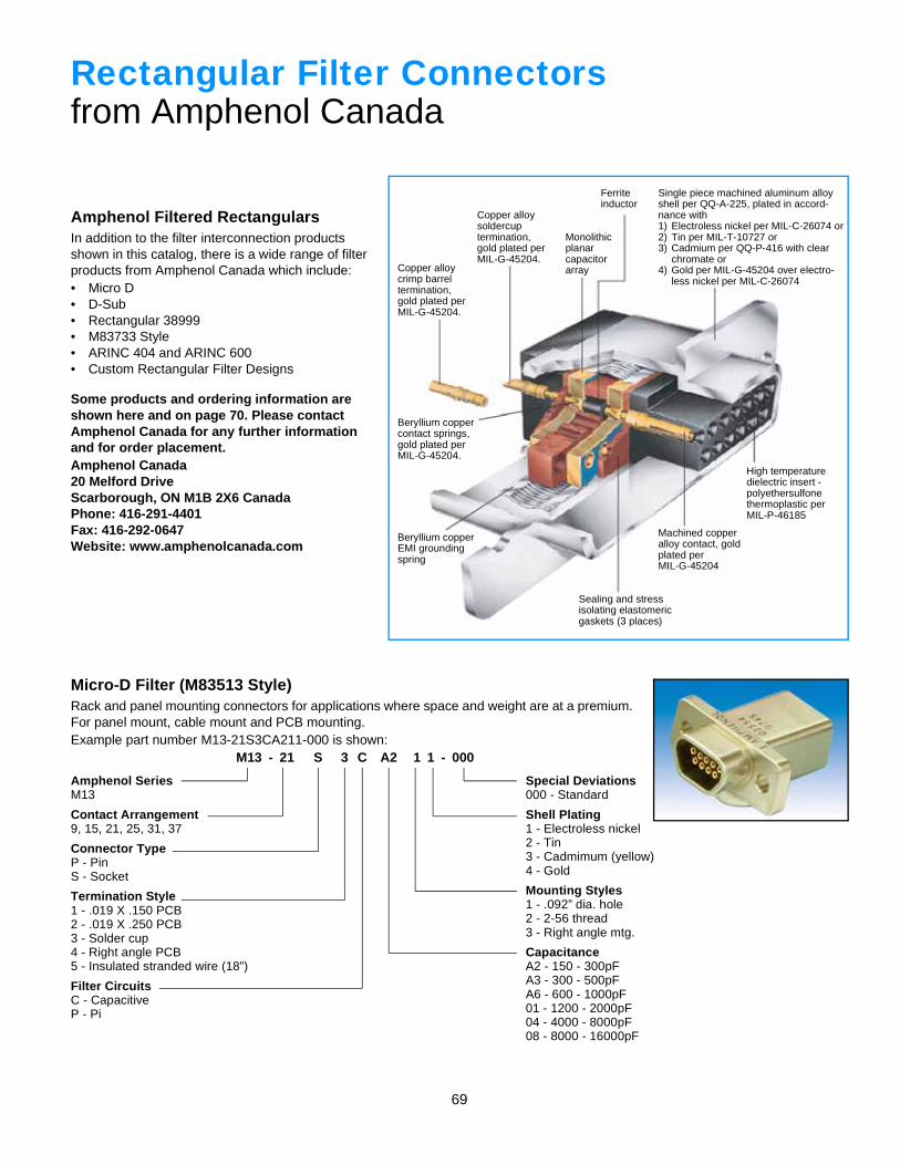
69
Amphenol Filtered RectangularsIn addition to the filter interconnection products shown in this catalog, there is a wide range of filter products from Amphenol Canada which include:• Micro D• D-Sub• Rectangular 38999• M83733 Style• ARINC 404 and ARINC 600• Custom Rectangular Filter Designs
Some products and ordering information are shown here and on page 70. Please contact Amphenol Canada for any further information and for order placement.Amphenol Canada20 Melford DriveScarborough, ON M1B 2X6 CanadaPhone: 416-291-4401Fax: 416-292-0647Website: www.amphenolcanada.com
Micro-D Filter (M83513 Style)Rack and panel mounting connectors for applications where space and weight are at a premium. For panel mount, cable mount and PCB mounting.Example part number M13-21S3CA211-000 is shown:
M13 - 21 S 3 C A2 1 1 - 000
Amphenol SeriesM13
Contact Arrangement9, 15, 21, 25, 31, 37
Connector TypeP - PinS - Socket
Termination Style1 - .019 X .150 PCB2 - .019 X .250 PCB3 - Solder cup4 - Right angle PCB5 - Insulated stranded wire (18”)
Filter CircuitsC - CapacitiveP - Pi
Special Deviations000 - Standard
Shell Plating1 - Electroless nickel2 - Tin3 - Cadmimum (yellow)4 - Gold
Mounting Styles1 - .092” dia. hole2 - 2-56 thread3 - Right angle mtg.
CapacitanceA2 - 150 - 300pFA3 - 300 - 500pFA6 - 600 - 1000pF01 - 1200 - 2000pF04 - 4000 - 8000pF08 - 8000 - 16000pF
Rectangular Filter Connectorsfrom Amphenol Canada
Single piece machined aluminum alloy shell per QQ-A-225, plated in accord-nance with1) Electroless nickel per MIL-C-26074 or2) Tin per MIL-T-10727 or3) Cadmium per QQ-P-416 with clear
chromate or4) Gold per MIL-G-45204 over electro-
less nickel per MIL-C-26074
Ferriteinductor
Monolithicplanarcapacitorarray
Copper alloysoldercuptermination, gold plated per MIL-G-45204.
Copper alloycrimp barreltermination, gold plated per MIL-G-45204.
Beryllium coppercontact springs, gold plated per MIL-G-45204.
Beryllium copperEMI groundingspring
High temperature dielectric insert -polyethersulfonethermoplastic perMIL-P-46185
Machined copper alloy contact, gold plated perMIL-G-45204
Sealing and stressisolating elastomericgaskets (3 places)
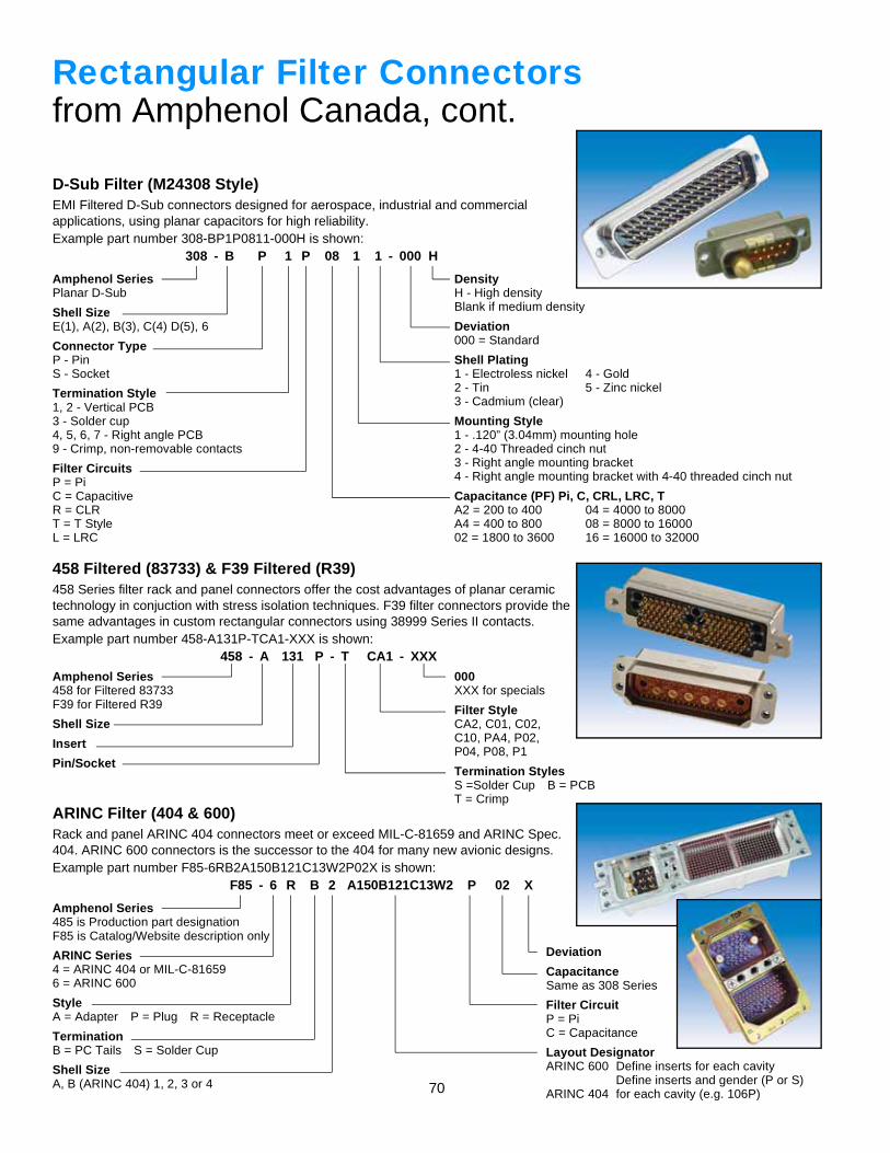
70
D-Sub Filter (M24308 Style)EMI Filtered D-Sub connectors designed for aerospace, industrial and commercialapplications, using planar capacitors for high reliability.Example part number 308-BP1P0811-000H is shown:
308 - B P 1 P 08 1 1 - 000 H
Rectangular Filter Connectorsfrom Amphenol Canada, cont.
Amphenol SeriesPlanar D-Sub
Shell SizeE(1), A(2), B(3), C(4) D(5), 6
Connector TypeP - PinS - Socket
Termination Style1, 2 - Vertical PCB3 - Solder cup4, 5, 6, 7 - Right angle PCB9 - Crimp, non-removable contacts
Filter CircuitsP = PiC = CapacitiveR = CLRT = T StyleL = LRC
DensityH - High densityBlank if medium density
Deviation000 = Standard
Shell Plating1 - Electroless nickel 4 - Gold2 - Tin 5 - Zinc nickel3 - Cadmium (clear)
Mounting Style1 - .120” (3.04mm) mounting hole2 - 4-40 Threaded cinch nut3 - Right angle mounting bracket4 - Right angle mounting bracket with 4-40 threaded cinch nut
Capacitance (PF) Pi, C, CRL, LRC, TA2 = 200 to 400 04 = 4000 to 8000A4 = 400 to 800 08 = 8000 to 1600002 = 1800 to 3600 16 = 16000 to 32000
458 Filtered (83733) & F39 Filtered (R39)458 Series filter rack and panel connectors offer the cost advantages of planar ceramictechnology in conjuction with stress isolation techniques. F39 filter connectors provide thesame advantages in custom rectangular connectors using 38999 Series II contacts.Example part number 458-A131P-TCA1-XXX is shown:
458 - A 131 P - T CA1 - XXX
Amphenol Series458 for Filtered 83733F39 for Filtered R39
Shell Size
Insert
Pin/Socket
000XXX for specials
Filter StyleCA2, C01, C02,C10, PA4, P02,P04, P08, P1
Termination StylesS =Solder Cup B = PCBT = Crimp
ARINC Filter (404 & 600)Rack and panel ARINC 404 connectors meet or exceed MIL-C-81659 and ARINC Spec.404. ARINC 600 connectors is the successor to the 404 for many new avionic designs.Example part number F85-6RB2A150B121C13W2P02X is shown:
F85 - 6 R B 2 A150B121C13W2 P 02 X
Amphenol Series485 is Production part designationF85 is Catalog/Website description only
ARINC Series4 = ARINC 404 or MIL-C-816596 = ARINC 600
StyleA = Adapter P = Plug R = Receptacle
TerminationB = PC Tails S = Solder Cup
Shell SizeA, B (ARINC 404) 1, 2, 3 or 4
Deviation
CapacitanceSame as 308 Series
Filter CircuitP = PiC = Capacitance
Layout DesignatorARINC 600 Define inserts for each cavity
Define inserts and gender (P or S)ARINC 404 for each cavity (e.g. 106P)
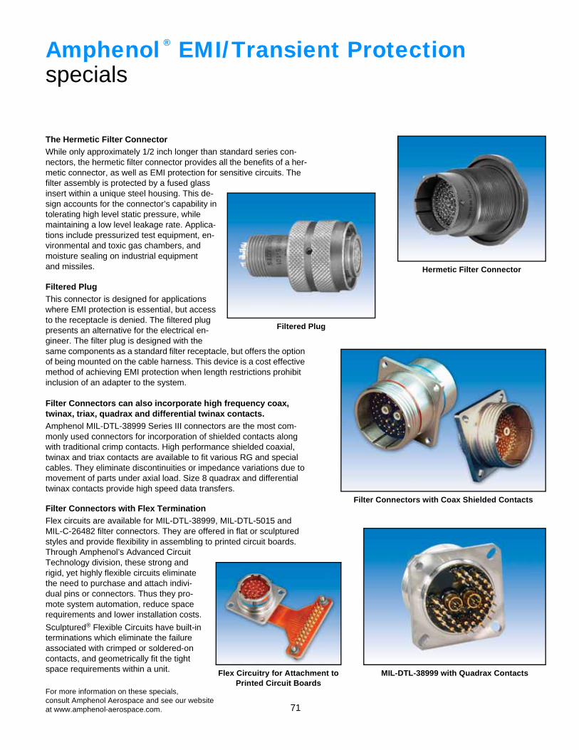
71
The Hermetic Filter ConnectorWhile only approximately 1/2 inch longer than standard series con-nectors, the hermetic filter connector provides all the benefits of a her-metic connector, as well as EMI protection for sensitive circuits. The filter assembly is protected by a fused glassinsert within a unique steel housing. This de-sign accounts for the connector’s capability intolerating high level static pressure, whilemaintaining a low level leakage rate. Applica-tions include pressurized test equipment, en-vironmental and toxic gas chambers, andmoisture sealing on industrial equipmentand missiles.
Filtered Plug This connector is designed for applicationswhere EMI protection is essential, but accessto the receptacle is denied. The filtered plugpresents an alternative for the electrical en-gineer. The filter plug is designed with thesame components as a standard filter receptacle, but offers the option of being mounted on the cable harness. This device is a cost effective method of achieving EMI protection when length restrictions prohibit inclusion of an adapter to the system.
Filter Connectors can also incorporate high frequency coax,twinax, triax, quadrax and differential twinax contacts.Amphenol MIL-DTL-38999 Series III connectors are the most com-monly used connectors for incorporation of shielded contacts along with traditional crimp contacts. High performance shielded coaxial, twinax and triax contacts are available to fit various RG and special cables. They eliminate discontinuities or impedance variations due to movement of parts under axial load. Size 8 quadrax and differential twinax contacts provide high speed data transfers.
Filter Connectors with Flex TerminationFlex circuits are available for MIL-DTL-38999, MIL-DTL-5015 and MIL-C-26482 filter connectors. They are offered in flat or sculptured styles and provide flexibility in assembling to printed circuit boards. Through Amphenol’s Advanced CircuitTechnology division, these strong andrigid, yet highly flexible circuits eliminatethe need to purchase and attach indivi-dual pins or connectors. Thus they pro-mote system automation, reduce spacerequirements and lower installation costs.
Sculptured® Flexible Circuits have built-interminations which eliminate the failureassociated with crimped or soldered-oncontacts, and geometrically fit the tightspace requirements within a unit.
For more information on these specials,consult Amphenol Aerospace and see our websiteat www.amphenol-aerospace.com.
Amphenol EMI/Transient Protectionspecials
®
Filter Connectors with Coax Shielded Contacts
MIL-DTL-38999 with Quadrax ContactsFlex Circuitry for Attachment to Printed Circuit Boards
Hermetic Filter Connector
Filtered Plug