Embed Size (px)
Citation preview
Contact Amphenol Aerospace for more information at 800-678-0141 or [email protected] • www.amphenol-aerospace.com268
AmphenolEMI/EMP Filter Protection
TABLE OF CONTENTSEMI/EMP Filter Protection Connectors - For Protection of Sensitive Circuits• Filter Product Overview, Advantages . . . . . . . . . . . . . . . . . 269• EMI Capabilities . . . . . . . . . . . . . . . . . . . . . . . 270, 271• Filter Connector Options/Specials . . . . . . . . . . . . . . . . 272, 273• Filter Selection Data . . . . . . . . . . . . . . . . . . . . . . . 274• Effect of Temperature on EMI Filter, Attenuation Curves . . . . . . . . . 275• Impedance Matching Formula . . . . . . . . . . . . . . . . . . . 276• Quality Assurance Testing . . . . . . . . . . . . . . . . . . . . . 277
Filter Connector Shell Styles:• How to Order-Standard . . . . . . . . . . . . . . . . . . . . 278-279• How to Order-Special/EMI Check Sheet . . . . . . . . . . . . . . . 280• Filter MIL-DTL-38999, Series III - FTV Aluminum / FCTV Composite . . . . 281 • How to Order-Two Week Filter Connectors . . . . . . . . . . . . . . 282• Two Week Filter Styles, Jam Nut /Wall Mount Receptacles . . . . . . . . 283• Filter MIL-DTL-38999, Series III - FCTV Composite Shell Styles . . . . 284-287• Filter MIL-DTL-38999, Series III - FTV Aluminum Shell Styles . . . . . 288-293
• Filter MIL-DTL-38999, Series II - FJT Aluminum . . . . . . . . . . 294-300
• Filter MIL-DTL-38999, Series I - FLJT Aluminum . . . . . . . . . . 301-310
• Filter SJT Series (MIL-DTL-38999 type) - FSJT Aluminum . . . . . . 311-314
• Filter MIL-DTL-38999 Series IV - FBL Aluminum . . . . . . . . . . 315, 316
• Filter MIL-DTL-26482 - FPT Aluminum . . . . . . . . . . . . . . 317-322
• Filter “AN” Series, MIL-DTL-5015 - FAN Aluminum . . . . . . . . . 323, 324
• Filter Adapters . . . . . . . . . . . . . . . . . . . . . . . . . . 325• Transient Protection MOV (Metal Oxide Varistor) Connectors . . . . . 326, 327• Transient Protection Diode Connectors . . . . . . . . . . . . . . 328, 329• Transient Protection ESA (Energy Shunting Assembly) Connectors . . . . . 330• EMI/Transient Protection Specials . . . . . . . . . . . . . . . . . . 331
EMI/EMP Filter Connector Typical Markets:• Military & Commercial Aviation• Military Vehicles• Missiles & Ordnance AmphenolAerospace
Planar Array Assembly
Capacitor and MOV Planars
Diode Contacts
• UAV• Space & Satellites• C4ISR
Contact Amphenol Aerospace for more information at 800-678-0141 or [email protected] • www.amphenol-aerospace.com 269
AmphenolAerospace
II Dualok
III
SJT
38999
I
PCB
Accessories
Aquacon
HD
EMI Filter
Transient
Herm/Seal
Fiber Optics
ContactsConnectorsCables
HIgH SPEED
26482M
atrix 2 83723 IIIM
atrix|Pyle5015
Crimp Rear
Release M
atrix
26500 Pyle
22992 C
lass L Back- Shells
Options
Others
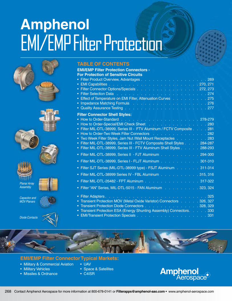
Amphenol® EMI/EMP Protection Connectors offer the versa tility of standard connectors with EMI/EMP protection for sensitive circuits. Internal housing of the EMI/EMP devices eliminates costly and bulky exterior discrete protection devices.
Virtually all major MIL-Spec circulars can be incorporated with filter devices:
• MIL-DTL-38999 • MIL-DTL-5015• MIL-DTL-26482 • MIL-DTL-27599• MIL-DTL-83723 • MIL-DTL-26500
FJTSubminiature JT, MIL-DTL-38999 Series II with Filter Protection.
FLJTSubminiature LJT, MIL-DTL-38999 Series I with Filter Protection.
FCTV with Stand-off FlangeFiltered Tri-Start connectors with composite shells for attachment to printed circuit boards.
EMI/EMP Filter Protection ConnectorsFor Protection of Sensitive Circuits
Filter AN ConnectorMIL-DTL-5015 Type Connectors with Filter Protection.
FPTMiniature MIL-DTL-26482 Series I with Filter Protection.
Page 281
Page 301
Page 323
Page 294
Page 286
Page 317
FTVSubminiature Tri-Start, MIL-DTL-38999 Series III, Metal or Composite shells with Filter Protection.
Rectangular Connectors available by Amphenol:• MIL-DTL-24308 D-Sub• MIL-DTL-83513 Micro D• ARINC 404/600• DOD-83527 Rack and Panel• MIL-DTL-83733 Rack and Panel
Rectangular filter interconnects are manufactured and sup plied by Amphenol Canada (www.amphenolcanada.com).
Overview
Mil-Spec
Rectangular
High Density HD38999• Provide 30% more contacts• Work with existing mil-specified 38999 shells• Utilize mil-qualified 39029 size 23 contact• Available in Mil-Spec or filter length shells
Page 46
Available in Filter, Hermetic & Epoxy Seal
2M• Ideal where space is limited• High density interconnect• Light weight• Intermateable & inter-mountable with Glenair’s “Might Mouse”
Available in Filter, Hermetic & Epoxy Seal
For more information visit www.amphenol-aerospace.com. The Micro-Miniature Catalog 12-M1 is online or contact an Amphenol Salesperson for more information.
Page 565
Contact Amphenol Aerospace for more information at 800-678-0141 or [email protected] • www.amphenol-aerospace.com270
AmphenolAerospace
Dualok
III
SJT
38999
PCB
HD
EMI F
ilter
Tran
sien
t
I II
Accessories
Herm/Seal
Aquacon
Fiber Optics
ContactsConnectors
Cables
HIgH SPEED
2648
2M
atrix
2
8372
3 III
5015
2650
0 Py
le
2299
2 C
lass
L
Back
- Sh
ells
Opt
ions
O
ther
sCr
imp
Rear
Rele
ase
Mat
rix
Mat
rix|P
yle
EMI CapabilitiesFor Maximum Design Flexibility
AdvantagesAmphenol offers filter connectors, which can include:
• EMP protection using diodes• EMP protection utilizing metal oxide varistors (MOV’s)• Filtered plug connectors• Glass fused hermetic seal• ESD protection• Combinations of filtering devices within one
connector package
OptionsAdvantages of Filter Connectors:
• Reduction in overall weight and space with the elimina tion of external filter circuits
• Reduction of solder junctions• Increase in reliability due to fewer connections• Fragile filter elements protected by connector shell from
handling and environmental damage• Pre-testing from factory and ready for installation
Amphenol provides a wide range of filtering solutions. You can select your options for your particular interference threats - VHF, UHF, MF1, HF or other filter ranges, then cou-ple with a connector package of your choice. Or give Amphe nol your custom shell design requirements for assis-tance in designing your unique filter solution.
EMI Filter connectors are intended for use in temperatures from –55°C to +125°C. Attenuation will change with feed-through current and temperature.
To assure reliability, connectors may be subjected to an attenuation performance test verifying proper assembly and grounding of the filters. Attenuation data on filter per-formance is stated in reference to a 50 ohm impedance system in order to allow filter performance to be more eas ily translated into real world impedances. Those inter-ested in determining the expected filter perfor mance in an impedance system other than 50 ohms may refer to page 285 of this catalog or may contact Amphenol Aerospace for further assistance.
It is suggested that the user(s) analyze their system require ments for EMI protection in the following areas:
• Working voltage (DC or AC and Frequency)• Peak voltage• Desired attenuation at a given frequency level• Any special capacitance limitations
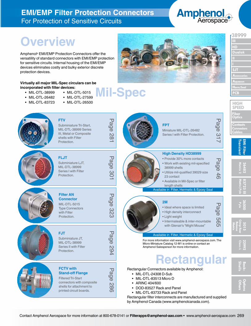
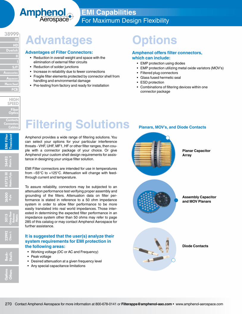
Planar Capacitor Array
Diode Contacts
Planars, MOV’s, and Diode ContactsFiltering Solutions
Assembly Capacitor and MOV Planars
Contact Amphenol Aerospace for more information at 800-678-0141 or [email protected] • www.amphenol-aerospace.com 271
AmphenolAerospace
II Dualok
III
SJT
38999
I
PCB
Accessories
Aquacon
HD
EMI Filter
Transient
Herm/Seal
Fiber Optics
ContactsConnectorsCables
HIgH SPEED
26482M
atrix 2 83723 IIIM
atrix|Pyle5015
Crimp Rear
Release M
atrix
26500 Pyle
22992 C
lass L Back- Shells
Options
Others
EMI CapabilitiesFor Maximum Design Flexibility
Options
Contact Options:• Coaxial, concentric twinax, triax and quadrax contacts
can be included in arrangements of filtered contacts for signal or power circuits (Please refer to the High Speed Contacts Section for High Frequency Contacts for Multi-Pin Connectors).
• Filter contacts with differing cut-off frequencies can be mixed in any given insert arrangement. (ratio 100:1 typical)
• Ground, insulated or filter contacts can be combined within the same connector to meet unique or changing frequency protec tion requirements.
• Thermocouple contacts• Diodes or MOV for EMP
EMI Capabilities For Maximum Design Flexibility, Continued
* More in-depth information on attenuation is available in: L-1146, General Design Guideline for EMI Filters and/or TVS (Transient Voltage Suppression) Connectors.Also for further information ask for:
L-1145, How to Specify Filter Connectors.
Contacts
Wire Terminations
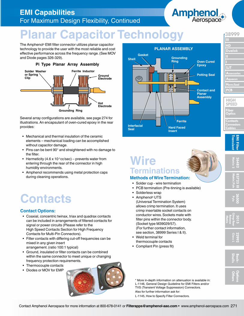
The Amphenol® EMI filter connector utilizes planar capacitor technology to provide the user with the most reliable and cost effective performance across the frequency range. (See MOV and Diode pages 326-329).
Several array configurations are available, see page 274 for illustrations. An encapsulant of oven-cured epoxy in the rear provides:
• Mechanical and thermal insulation of the ceramic elements – mechanical loading can be accomplished without capaci tor damage.
• Pins can be bent 90° and straightened with no damage to the filter.
• Hermeticity (4.6 x 10⁻³ cc/sec) – prevents water from enter ing through the rear of the connector in high humidity envi ronments.
• Amphenol recommends using metal protection caps during cleaning operations.
PLANAR ASSEMBLY
GasketShell Grounding
Ring Oven CuredEpoxy
Potting Seal
Contact andPlanarAssembly
Ferrite
Hard FacedInsert
InterfacialSeal
Pi Type Planar Array Assembly
Ferrite Inductor
GroundElectrode
Solder Washeror SpringClip
Grounding Ring
HotElectrode
Planar Capacitor Technology
Methods of Wire Termination:• Solder cup - wire termination• PCB termination (Pre-tinning is available)• Solderless wrap• Amphenol® UTS
(Universal Termination System) allows crimp termination. It uses crimp insertable socket contacts on con ductor wires. Sockets mate with filter pins within the connector body. (Socket type M39029/57). (For further contact informa tion, see section, 38999 Series I & II).
• Weld terminal for thermocouple contacts
• Compliant Pin (press fit)
Contact Amphenol Aerospace for more information at 800-678-0141 or [email protected] • www.amphenol-aerospace.com272
AmphenolAerospace
Dualok
III
SJT
38999
PCB
HD
EMI F
ilter
Tran
sien
t
I II
Accessories
Herm/Seal
Aquacon
Fiber Optics
ContactsConnectors
Cables
HIgH SPEED
2648
2M
atrix
2
8372
3 III
5015
2650
0 Py
le
2299
2 C
lass
L
Back
- Sh
ells
Opt
ions
O
ther
sCr
imp
Rear
Rele
ase
Mat
rix
Mat
rix|P
yle
Filter Connector Options
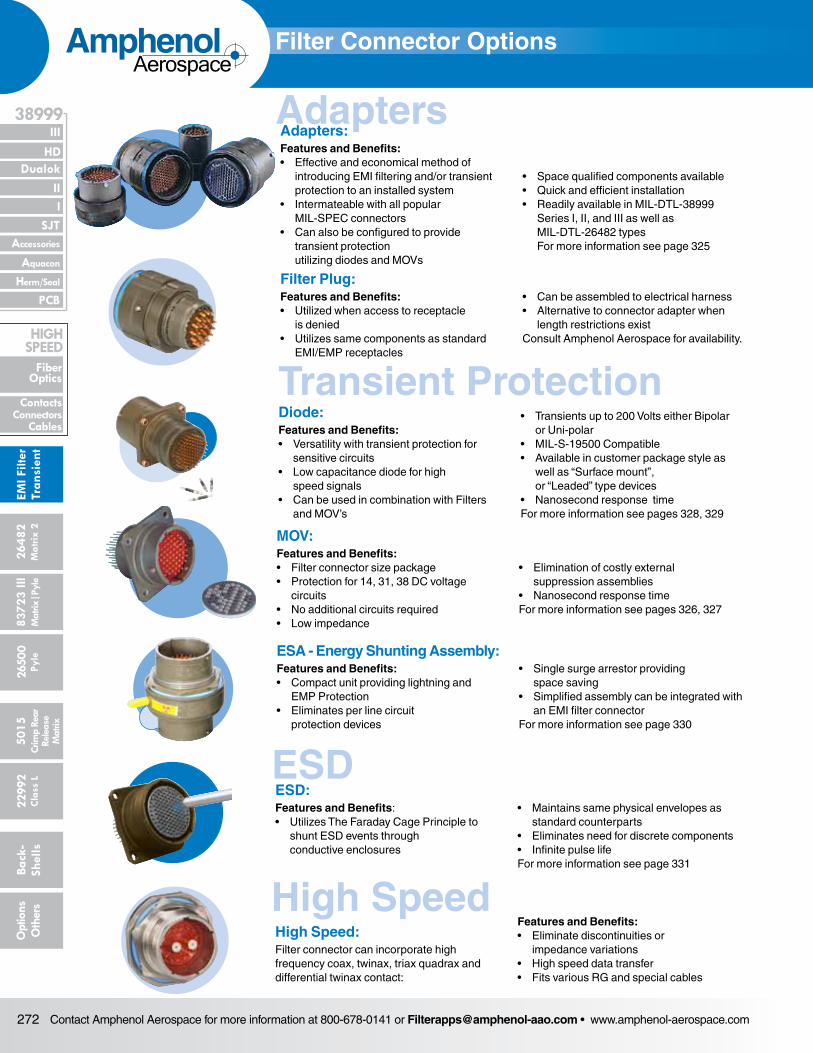
ESD:Features and Benefits:• Utilizes The Faraday Cage Principle to shunt ESD events through conductive enclosures
• Maintains same physical envelopes as standard counterparts• Eliminates need for discrete components• Infinite pulse lifeFor more information see page 331
ESA - Energy Shunting Assembly:Features and Benefits:• Compact unit providing lightning and EMP Protection• Eliminates per line circuit protection devices
• Single surge arrestor providing space saving • Simplified assembly can be integrated with an EMI filter connector For more information see page 330
Filter Plug:Features and Benefits:• Utilized when access to receptacle is denied• Utilizes same components as standard EMI/EMP receptacles
• Can be assembled to electrical harness• Alternative to connector adapter when length restrictions existConsult Amphenol Aerospace for availability.
MOV:Features and Benefits:• Filter connector size package• Protection for 14, 31, 38 DC voltage circuits• No additional circuits required• Low impedance
• Elimination of costly external suppression assemblies • Nanosecond response timeFor more information see pages 326, 327
AdaptersAdapters:Features and Benefits:• Effective and economical method of introducing EMI filtering and/or transient protection to an installed system• Intermateable with all popular MIL-SPEC connectors• Can also be configured to provide transient protection utilizing diodes and MOVs
• Space qualified components available• Quick and efficient installation• Readily available in MIL-DTL-38999 Series I, II, and III as well as MIL-DTL-26482 types For more information see page 325
Transient Protection
ESD
High Speed
Diode:Features and Benefits:• Versatility with transient protection for sensitive circuits• Low capacitance diode for high speed signals• Can be used in combination with Filters and MOV’s
• Transients up to 200 Volts either Bipolar or Uni-polar• MIL-S-19500 Compatible• Available in customer package style as well as “Surface mount”, or “Leaded” type devices• Nanosecond response timeFor more information see pages 328, 329
High Speed:Filter connector can incorporate high frequency coax, twinax, triax quadrax and differential twinax contact:
Features and Benefits:• Eliminate discontinuities or impedance variations• High speed data transfer• Fits various RG and special cables
Contact Amphenol Aerospace for more information at 800-678-0141 or [email protected] • www.amphenol-aerospace.com 273
AmphenolAerospace
II Dualok
III
SJT
38999
I
PCB
Accessories
Aquacon
HD
EMI Filter
Transient
Herm/Seal
Fiber Optics
ContactsConnectorsCables
HIgH SPEED
26482M
atrix 2 83723 IIIM
atrix|Pyle5015
Crimp Rear
Release M
atrix
26500 Pyle
22992 C
lass L Back- Shells
Options
Others
Filter Connector Options EMI/Transient ProtectionSpecials
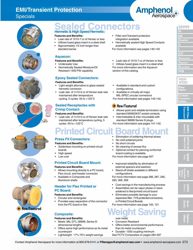
Header for Flex Printed or PC Board:Features and Benefits:• Circular and rectangular• Provides easy separation of the connector from the PC board or flex
• Cost savings in the manufacturing process• Assemblies can be vapor phase or wave soldered to flex/printed circuit board • Eliminates possible damage to your expensive filter ,TVS protected connectors, or Printed Circuit Boards For more information see page 120, 121
Sealed Receptacles with Crimp Contact:Features and Benefits:• Leak rate of 1x10⁻⁵ cc of He/sec leak rate maintained after temperature cycling, 5 cycles -55 to +125°C
• Allows quick and reliable termination using standard M39029/57 socket contacts.• Intermateable & inter-mountable with standard 38999 Series III plugs. For more information see pages 141-142.
Printed Circuit Board Mount:Features and Benefits:• Allows mounting directly to a PC board, Flex circuit, and header connector• Available in Composite and Aluminum shells
• Improved reliability by elimination of external spacers and washers• Stand-off shells available in different configurationsFor more information see page 286, 287, 292, 293, 306, 309
Epoxy Sealed Connectors:Features and Benefits:• Light weight alternative to glass sealed hermetic connector• Leak rate of 1x10⁻⁵ cc of He/sec leak rate maintained after temperature cycling, 5 cycles -55 to +125°C
• Available in standard and custom configurations.• Available in virtually all major MIL-SPEC circular connectorsFor more information see pages 140-142.
Aquacon:Features and Benefits:• Underwater Use• Hermetically Sealed-Moisture/Oil Resistant 1500 PSI capability
• Leak rate of 1X10⁻⁷ cc of He/sec or less• Utilizes fused glass insert in a steel shellFor more information see the Aquacon section of this catalog.
Sealed ConnectorsHermetic & High Speed Hermetic:Features and Benefits:• Leak rate of 1X10⁻⁷ cc of He/sec or less• Utilizes fused glass insert in a steel shell• Approximately 1/2 inch longer than standard series
• Filter and Transient protection integration available.• Hermetically sealed High Speed Contacts availableFor more information see pages 140-142
Printed Circuit Board MountPress Fit Connectors:Features and Benefits:• Solderless mounting on printed circuit boards• High speed• Low cost
• Elimination of soldering thermal stress• No cold soldered joints• No short circuits • No cleaning of excess flux• Optional contact for piercing conformal board coating is available.For more information see page 557
Weight SavingComposite:Features and Benefits:• Meets MIL-DTL-38999, Series III dimensional lengths• Offers same high performance as its metal counterpart• Lightweight: 17%-70% weight savings
over metal• Corrosion Resistant• Offers better environmental performance than its metal counterpart• Durable- 1500 coupling minimum See FCTV Composites on pages 284-287
New/Featured
New/Featured
Contact Amphenol Aerospace for more information at 800-678-0141 or [email protected] • www.amphenol-aerospace.com274
AmphenolAerospace
Dualok
III
SJT
38999
PCB
HD
EMI F
ilter
Tran
sien
t
I II
Accessories
Herm/Seal
Aquacon
Fiber Optics
ContactsConnectors
Cables
HIgH SPEED
2648
2M
atrix
2
8372
3 III
5015
2650
0 Py
le
2299
2 C
lass
L
Back
- Sh
ells
Opt
ions
O
ther
sCr
imp
Rear
Rele
ase
Mat
rix
Mat
rix|P
yle
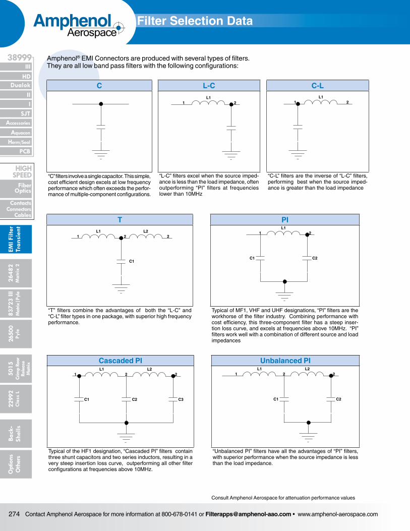
Amphenol® EMI Connectors are produced with several types of filters. They are all low band pass filters with the following configurations:
Pi -Typical of the VHF, UHF and MF filter
Cascaded Pi -Typical of the HF filter. It consists of three planar arrays on a common pin.
Capacitor *-Consists of a feed-through capacitor without any ferrite. It can be 50pf to 1µf and carry the MF, HF and VHF designation depending on its typical 50dB performance.L-C *-Typical of HF, VHF and UHF filter. Low source / high load impedance.
C-L *-Typical of HF, VHF and UHF filter. High load impedance / low source.
T *-Typical of HF, VHF and UHF filter. Low source / low load impedance.* Consult factory for attenuation performance values.
Parameters
Medium Frequency FilterF
High Frequency FilterF
Very High Frequency Filter
Ultra High Frequency Filter
MF-1 (Pi)
HF-1 (Cascaded Pi)
VHF-1 (Pi)
VHF-2† (Pi)
UHF-1† (Pi)
UHF-2† (Pi)
Minimum Attenuation
(Test Points)*
150kHz 20dB – – – – –
15MHz – 50dB – – – –
50MHz – 80dB – – – –
100MHz 80dB – 62dB 46dB 18dB 28dB
Maximum Working Voltage (User must specify DC or
AC)††††DC††† 50VDC 200VDC 200VDC 200VDC 200VDC 200VDC
Dielectric Withstanding Voltage Capability (for 5 sec. with 10 milliamperes
max. charging current)FF
100 volts DC
500 volts DC
500 volts DC
500 volts DC
500volts DC
500 volts DC
Maximum Feed-thru Current
(DC and/or Audio Frequency R.M.S.)
Size 16 contacts 13.0 amps
13.0 amps
13.0amps
13.0 amps
13.0 amps
13.0 amps
Size 20 contacts 7.5amps
7.5 amps
7.5 amps
7.5 amps
7.5 amps
7.5 amps
Size 22 contacts not available
5.0 amps
not available
5.0 amps
5.0 amps
5.0amps
High Density ContactSize 23 contacts not
available5.0
amps5.0
amps5.0
amps5.0
amps5.0
amps
Maximum RF Current 3.0 amps
3.0 amps
3.0amps
3.0amps
3.0 amps
3.0 amps
Minimum Insulation Resistance 250 megohms
10 gigaohms
10gigaohms
10 gigaohms
10 gigaohms
10gigaohms
Typical Capacitance** 1.0 microfarad
16 nanofarads
7 nanofarads
2.5 nanofarads
375 picofarads
710 picofarads
Air Leakage†† 4.6 x 10⁻³ cc/sec (Higher sealing capabilities available upon request please consult factory)
Operating Temperature Range –55°C to +125°C
Filter Selection Data
C
“C” filters involve a single capacitor. This simple, cost efficient design excels at low frequency performance which often exceeds the perfor-mance of multiple-component configurations.
L-C
“L-C” filters excel when the source imped-ance is less than the load impedance, often outperforming “PI” filters at frequencies lower than 10MHz
21L1
C-L
“C-L” filters are the inverse of “L-C” filters, performing best when the source imped-ance is greater than the load impedance
21L1
T
“T” filters combine the advantages of both the “L-C” and “C-L” filter types in one package, with superior high frequency performance.
21 2L1 L2
C1
PI
Typical of MF1, VHF and UHF designations, “PI” filters are the workhorse of the filter industry. Combining performance with cost efficiency, this three-component filter has a steep inser-tion loss curve, and excels at frequencies above 10MHz. “PI” filters work well with a combination of different source and load impedances
21
C1 C2
L1
Cascaded PI
Typical of the HF1 designation, “Cascaded PI” filters contain three shunt capacitors and two series inductors, resulting in a very steep insertion loss curve, outperforming all other filter configurations at frequencies above 10MHz.
Unbalanced PI
“Unbalanced PI” filters have all the advantages of “PI” filters, with superior performance when the source impedance is less than the load impedance.
22
C1 C2
L21
L122
C2 C3C1
L21
L1
Consult Amphenol Aerospace for attenuation performance values
Contact Amphenol Aerospace for more information at 800-678-0141 or [email protected] • www.amphenol-aerospace.com 275
AmphenolAerospace
II Dualok
III
SJT
38999
I
PCB
Accessories
Aquacon
HD
EMI Filter
Transient
Herm/Seal
Fiber Optics
ContactsConnectorsCables
HIgH SPEED
26482M
atrix 2 83723 IIIM
atrix|Pyle5015
Crimp Rear
Release M
atrix
26500 Pyle
22992 C
lass L Back- Shells
Options
Others
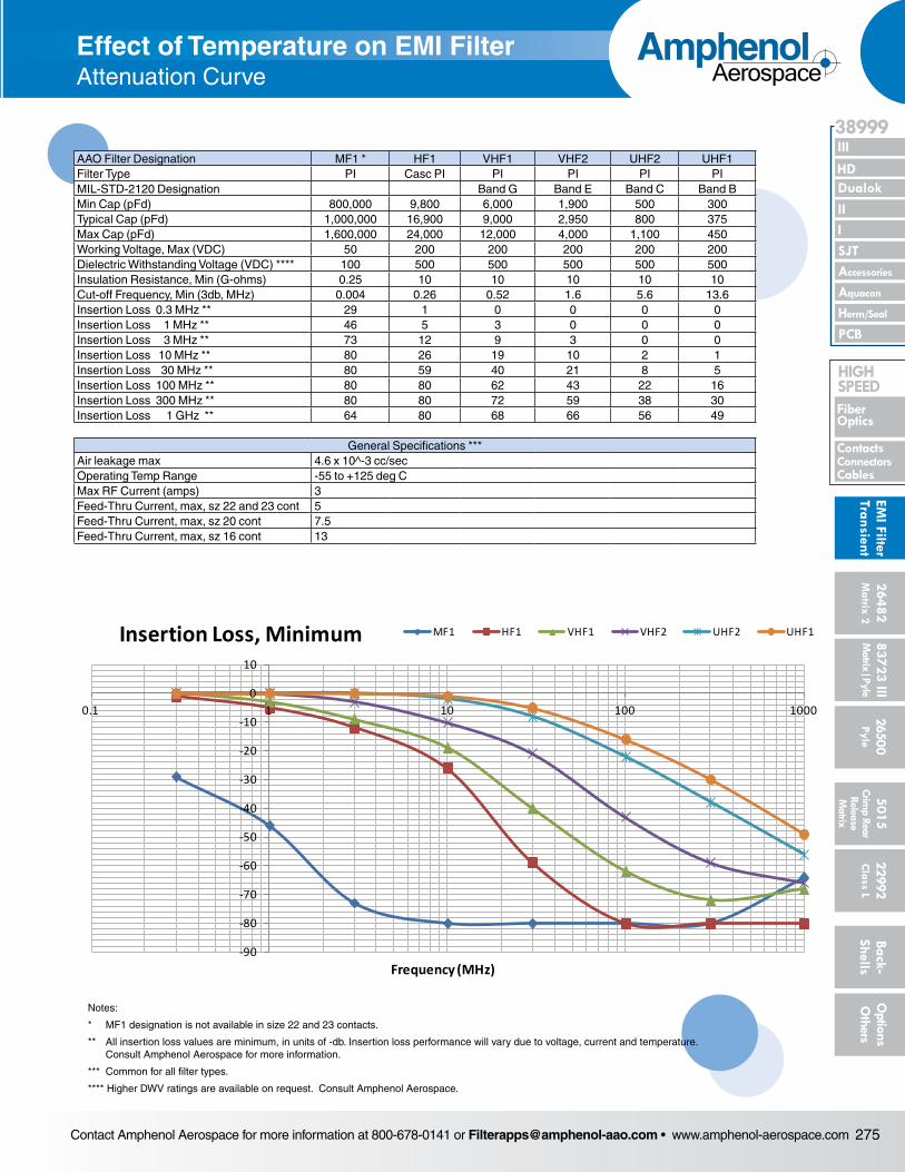
Effect of Temperature on EMI FilterAttenuation Curve
-90
-80
-70
-60
-50
-40
-30
-20
-10
0
10
0.1 1 10 100 1000
Inse
rtio
nLo
ss (d
b)
Frequency (MHz)
Insertion Loss, Minimum MF1 HF1 VHF1 VHF2 UHF2 UHF1
AAO Filter Designation MF1 * HF1 VHF1 VHF2 UHF2 UHF1Filter Type PI Casc PI PI PI PI PIMIL-STD-2120 Designation Band G Band E Band C Band BMin Cap (pFd) 800,000 9,800 6,000 1,900 500 300Typical Cap (pFd) 1,000,000 16,900 9,000 2,950 800 375Max Cap (pFd) 1,600,000 24,000 12,000 4,000 1,100 450Working Voltage, Max (VDC) 50 200 200 200 200 200Dielectric Withstanding Voltage (VDC) **** 100 500 500 500 500 500Insulation Resistance, Min (G-ohms) 0.25 10 10 10 10 10Cut-off Frequency, Min (3db, MHz) 0.004 0.26 0.52 1.6 5.6 13.6Insertion Loss 0.3 MHz ** 29 1 0 0 0 0Insertion Loss 1 MHz ** 46 5 3 0 0 0Insertion Loss 3 MHz ** 73 12 9 3 0 0Insertion Loss 10 MHz ** 80 26 19 10 2 1Insertion Loss 30 MHz ** 80 59 40 21 8 5Insertion Loss 100 MHz ** 80 80 62 43 22 16Insertion Loss 300 MHz ** 80 80 72 59 38 30Insertion Loss 1 GHz ** 64 80 68 66 56 49
General Specifications ***Air leakage max 4.6 x 10^-3 cc/secOperating Temp Range -55 to +125 deg CMax RF Current (amps) 3Feed-Thru Current, max, sz 22 and 23 cont 5Feed-Thru Current, max, sz 20 cont 7.5Feed-Thru Current, max, sz 16 cont 13
Notes:
* MF1 designation is not available in size 22 and 23 contacts.
** All insertion loss values are minimum, in units of -db. Insertion loss performance will vary due to voltage, current and temperature. Consult Amphenol Aerospace for more information.
*** Common for all filter types.
**** Higher DWV ratings are available on request. Consult Amphenol Aerospace.
Contact Amphenol Aerospace for more information at 800-678-0141 or [email protected] • www.amphenol-aerospace.com276
AmphenolAerospace
Dualok
III
SJT
38999
PCB
HD
EMI F
ilter
Tran
sien
t
I II
Accessories
Herm/Seal
Aquacon
Fiber Optics
ContactsConnectors
Cables
HIgH SPEED
2648
2M
atrix
2
8372
3 III
5015
2650
0 Py
le
2299
2 C
lass
L
Back
- Sh
ells
Opt
ions
O
ther
sCr
imp
Rear
Rele
ase
Mat
rix
Mat
rix|P
yle
0
20
60
40
80
100
120
140
Att
enua
tion
- dB
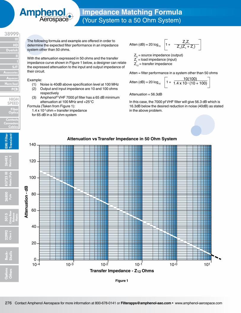
Attenuation vs Transfer Impedance in 50 Ohm System
Transfer Impedance - Z Ohms10 1010101010
12
1-0-1-2-3-4
Atten (dB) = 20 log10 1 +
ZS = source impedance (output)ZL = load impedance (input)Z12 = transfer impedance
Atten = filter performance in a system other than 50 ohms
Atten (dB) = 20 log10 1 +
Attenuation = 56.3dB
In this case, the 7000 pf VHF filter will give 56.3 dB which is 16.3dB below the desired reduction in noise (40dB) as stated in the above problem.
ZSZL
Z12(ZS + ZL)
10(100)1.4 x 10⁻² (10 + 100)
Figure 1
Impedance Matching Formula(Your System to a 50 Ohm System)
The following formula and example are offered in order to deter mine the expected filter performance in an impedance system other than 50 ohms.
With the attenuation expressed in 50 ohms and the transfer impedance curve shown in Figure 1 below, a designer can relate the expressed attenuation to the input and output imped ance of their circuit.
Example: (1) Noise is 40dB above specification level at 100 MHz (2) Output and input impedance are 10 and 100 ohms
respectively (3) Amphenol® VHF 7000 pf filter has a 65 dB minimum
attenuation at 100 MHz and +25°CFormula (Taken from Figure 1): 1.4 x 10⁻² ohm = transfer impedance
for 65 dB in a 50 ohm system
Contact Amphenol Aerospace for more information at 800-678-0141 or [email protected] • www.amphenol-aerospace.com 277
AmphenolAerospace
II Dualok
III
SJT
38999
I
PCB
Accessories
Aquacon
HD
EMI Filter
Transient
Herm/Seal
Fiber Optics
ContactsConnectorsCables
HIgH SPEED
26482M
atrix 2 83723 IIIM
atrix|Pyle5015
Crimp Rear
Release M
atrix
26500 Pyle
22992 C
lass L Back- Shells
Options
Others
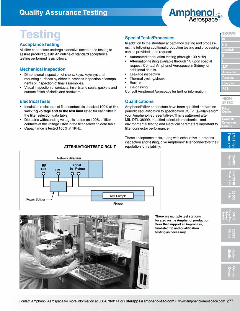
Network Analyzer
Power SplitterFixture
RFOut Ref
SignalIn Return
Test Sample
Acceptance TestingAll filter connectors undergo extensive acceptance testing to assure product quality. An outline of standard accep tance testing performed is as follows:
Mechanical Inspection• Dimensional inspection of shells, keys, keyways and
mount ing surfaces by either in-process inspection of compo-nents or inspection of final assemblies.
• Visual inspection of contacts, inserts and seals, gaskets and surface finish of shells and hardware.
Electrical Tests• Insulation resistance of filter contacts is checked 100% at the
working voltage and to the test limit listed for each fil ter in the filter selection data table.
• Dielectric withstanding voltage is tested on 100% of filter contacts at the voltage listed in the filter selection data table.
• Capacitance is tested 100% at 1KHz.
Special Tests/ProcessesIn addition to the standard acceptance testing and process-es, the following additional production testing and processing can be provided upon request:• Automated attenuation testing (through 100 MHz)• Attenuation testing available through 1G upon special
request. Contact Amphenol Aerospace in Sidney for additional details.
• Leakage inspection• Thermal cycling/shock• Burn-in• De-gassingConsult Amphenol Aerospace for further information.
QualificationsAmphenol® filter connectors have been qualified and are on periodic requalification to specification BSF-1 (available from your Amphenol representative). This is patterned after MIL-DTL-38999, modified to include mechanical and environmental testing and electrical parameters important to filter connector performance.
These acceptance tests, along with exhaustive in-process inspection and testing, give Amphenol® filter connectors their reputation for reliability.ATTENUATION TEST CIRCUIT
There are multiple test stations located on the Amphenol production floor that support all in-process, final electric and qualification testing as necessary.
Quality Assurance Testing
Testing
Contact Amphenol Aerospace for more information at 800-678-0141 or [email protected] • www.amphenol-aerospace.com278
AmphenolAerospace
Dualok
III
SJT
38999
PCB
HD
EMI F
ilter
Tran
sien
t
I II
Accessories
Herm/Seal
Aquacon
Fiber Optics
ContactsConnectors
Cables
HIgH SPEED
2648
2M
atrix
2
8372
3 III
5015
2650
0 Py
le
2299
2 C
lass
L
Back
- Sh
ells
Opt
ions
O
ther
sCr
imp
Rear
Rele
ase
Mat
rix
Mat
rix|P
yle
Federal Vendor Identification/FSCM 77820
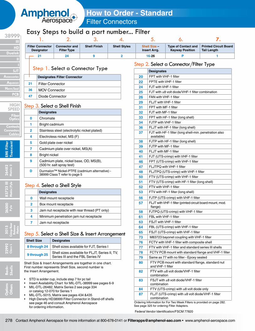
How to Order - StandardFilter Connectors
Step 1. Select a Connector Type
Filter Connector Designator
Connector and Filter Type
Shell Finish Shell Styles Shell Size – Insert Arrg.
Type of Contact and Keyway Position
Printed Circuit Board Tail Length
21 24 9 2 16-26 P 1
Designates Filter Connector
21 Filter Connector
36 MOV Connector
47 Diode Connector
Easy Steps to build a part number... Filter
Step 2. Select a Connector/Filter Type
1. 2. 3. 4. 5. 6. 7.
Designates
0 Chromate
1 Bright cadmium
2 Stainless steel (electrolytic nickel plated)
4 Electroless nickel, MS (F)
5 Gold plate over nickel
7 Cadmium plate over nickel, MS(A)
8 Bright nickel
9 Cadmium plate, nickel base, OD, MS(B), (500 hr. salt spray test)
D Durmalon™ Nickel-PTFE (cadmium alternative) - 38999 Class T refer to page 5
Step 3. Select a Shell Finish
Designates
0 Wall mount receptacle
2 Box mount receptacle
3 Jam nut receptacle with rear thread (PT only)
4 Minimum penetration jam nut receptacle
7 Jam nut receptacle
Step 4. Select a Shell Style
Designates
20 FPT with VHF-1 filter
22 FPTE with VHF-1 filter
24 FJT with VHF-1 filter
25 FJT with ±8 volt diode/VHF-1 filter combination
26 FAN with VHF-1 filter
29 FLJT with VHF-1 filter
31 FPT with MF-1 filter
32 FJT with MF-1 filter
33 FPT with HF-1 filter (long shell)
34 FJTP with VHF-1 filter
36 FLJT with HF-1 filter (long shell)
37 FJT with HF-1 filter (long shell-min. penetration also available)
38 FJTP with HF-1 filter (long shell)
39 FJTP with MF-1 filter
40 FLJT with MF-1 filter
41 FJT (UTS-crimp) with VHF-1 filter
46 FPT (UTS-crimp) with VHF-1 filter
47 FLJTPQ with VHF-1 filter
48 FLJTPQ (UTS-crimp) with VHF-1 filter
50 FTV (UTS-crimp) with VHF-1 filter
51 FTV (UTS-crimp) with HF-1 filter (long shell)
52 FTV with VHF-1 filter
53 FTV with HF-1 filter (long shell)
56 FJTP (UTS-crimp) with VHF-1 filter
57 FLJT with VHF-1 filter (printed circuit board mount, mod. flange)
58 FJTPQ (UTS-crimp) with VHF-1 filter
61 FBL with VHF-1 filter
63 FSJT with VHF-1 filter
64 FBL (UTS-crimp) with VHF-1 filter
65 FSJT (UTS-crimp) with VHF-1 filter
73 M83723 bayonet coupling with VHF-1 filter
76 FCTV with VHF-1 filter with composite shell
77 FTV with VHF-1 filter and standard series III shells
78 FCTV PCB mount with standard flange and VHF-1 filter
79 Same as 77 with no filter - Epoxy sealed
80 FTV PCB mount with standard flange, standard nut and VHF-1 filter
82 FTV with ±8 volt diode/VHF-1 filter combination
83 FSJT with ±8 volt diode/VHF-1 filter combination
84 FTV (UTS-crimp) with ±8 volt diode only
87 FLJT (UTS-crimp) with ±8 volt diode/VHF-1 filter combination
Ordering Information for For Two Week Filters is provided on page 282. See page 325 for ordering Filter Adapters.
Shell Size Designates
8 through 24 Shell sizes available for FJT, Series I
9 through 25 Shell sizes available for FLJT, Series II, TV, Series III and the FBL Series IV
Step 5. Select a Shell Size & Insert Arrangement
Shell Size & Insert Arrangements are together in one chart. First number represents Shell Size, second number is the Insert Arrangement.
• STD is solder cup, include step 7 for pc tail• Insert Availability Chart for MIL-DTL-38999 see pages 6-9• MIL-DTL-26482, Matrix Series 2 see page 334 or catalog 12-070 for Series 1• MIL-DTL-5015, Matrix see pages 434 &435 • High Density HD38999 Filter Connector in Stand-off shells see page 46 and consult Amphenol Aerospace for ordering information.
Contact Amphenol Aerospace for more information at 800-678-0141 or [email protected] • www.amphenol-aerospace.com 279
AmphenolAerospace
II Dualok
III
SJT
38999
I
PCB
Accessories
Aquacon
HD
EMI Filter
Transient
Herm/Seal
Fiber Optics
ContactsConnectorsCables
HIgH SPEED
26482M
atrix 2 83723 IIIM
atrix|Pyle5015
Crimp Rear
Release M
atrix
26500 Pyle
22992 C
lass L Back- Shells
Options
Others
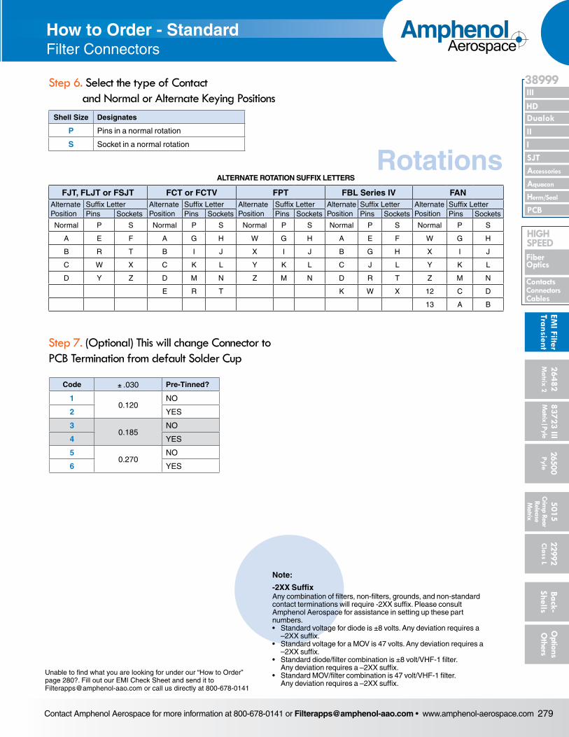
Shell Size Designates
P Pins in a normal rotation
S Socket in a normal rotation
Step 6. Select the type of Contact and Normal or Alternate Keying Positions
How to Order - StandardFilter Connectors
Step 7. (Optional) This will change Connector to PCB Termination from default Solder Cup
Code ± .030 Pre-Tinned?
1 0.120
NO
2 YES
30.185
NO
4 YES
50.270
NO
6 YES
Rotations
Note:
-2XX SuffixAny combination of filters, non-filters, grounds, and non-standard contact terminations will require -2XX suffix. Please consult Amphenol Aerospace for assistance in setting up these part numbers.• Standard voltage for diode is ±8 volts. Any devia tion requires a
–2XX suffix.• Standard voltage for a MOV is 47 volts. Any devi ation requires a
–2XX suffix.• Standard diode/filter combination is ±8 volt/VHF-1 filter.
Any deviation requires a –2XX suffix.• Standard MOV/filter combination is 47 volt/VHF-1 filter.
Any deviation requires a –2XX suffix.
Unable to find what you are looking for under our “How to Order” page 280?. Fill out our EMI Check Sheet and send it to [email protected] or call us directly at 800-678-0141
FJT, FLJT or FSJT FCT or FCTV FPT FBL Series IV FANAlternate Position
Suffix Letter Alternate Position
Suffix Letter Alternate Position
Suffix Letter Alternate Position
Suffix Letter Alternate Position
Suffix LetterPins Sockets Pins Sockets Pins Sockets Pins Sockets Pins Sockets
Normal P S Normal P S Normal P S Normal P S Normal P S
A E F A G H W G H A E F W G H
B R T B I J X I J B G H X I J
C W X C K L Y K L C J L Y K L
D Y Z D M N Z M N D R T Z M N
E R T K W X 12 C D
13 A B
ALTERNATE ROTATION SUFFIX LETTERS
Contact Amphenol Aerospace for more information at 800-678-0141 or [email protected] • www.amphenol-aerospace.com280
AmphenolAerospace
Dualok
III
SJT
38999
PCB
HD
EMI F
ilter
Tran
sien
t
I II
Accessories
Herm/Seal
Aquacon
Fiber Optics
ContactsConnectors
Cables
HIgH SPEED
2648
2M
atrix
2
8372
3 III
5015
2650
0 Py
le
2299
2 C
lass
L
Back
- Sh
ells
Opt
ions
O
ther
sCr
imp
Rear
Rele
ase
Mat
rix
Mat
rix|P
yle
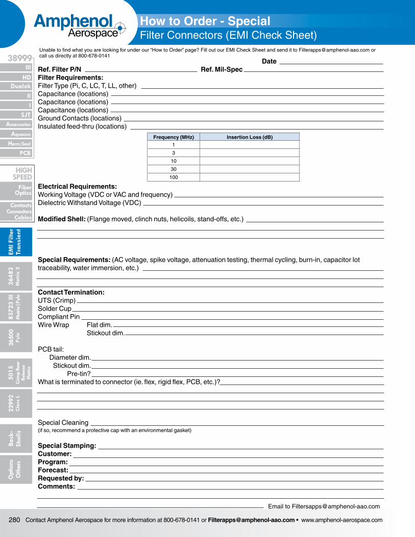
DateRef. Filter P/N Ref. Mil-SpecFilter Requirements:Filter Type (Pi, C, LC, T, LL, other) Capacitance (locations)Capacitance (locations)Capacitance (locations) Ground Contacts (locations) Insulated feed-thru (locations)
Frequency (MHz) Insertion Loss (dB)1
3
10
30
100
Electrical Requirements: Working Voltage (VDC or VAC and frequency)Dielectric Withstand Voltage (VDC)
Modified Shell: (Flange moved, clinch nuts, helicoils, stand-offs, etc.)
Special Requirements: (AC voltage, spike voltage, attenuation testing, thermal cycling, burn-in, capacitor lot traceabil ity, water immersion, etc.)
Contact Termination:UTS (Crimp)Solder CupCompliant PinWire Wrap Flat dim. Stickout dim.
PCB tail: Diameter dim. Stickout dim. Pre-tin?What is terminated to connector (ie. flex, rigid flex, PCB, etc.)?
Special Cleaning (if so, recommend a protective cap with an environmental gasket)
Special Stamping:Customer:Program:Forecast:Requested by:Comments:
How to Order - SpecialFilter Connectors (EMI Check Sheet)
Email to [email protected]
Unable to find what you are looking for under our “How to Order” page? Fill out our EMI Check Sheet and send it to [email protected] or call us directly at 800-678-0141
Contact Amphenol Aerospace for more information at 800-678-0141 or [email protected] • www.amphenol-aerospace.com 281
AmphenolAerospace
II Dualok
III
SJT
38999
I
PCB
Accessories
Aquacon
HD
EMI Filter
Transient
Herm/Seal
Fiber Optics
ContactsConnectorsCables
HIgH SPEED
26482M
atrix 2 83723 IIIM
atrix|Pyle5015
Crimp Rear
Release M
atrix
26500 Pyle
22992 C
lass L Back- Shells
Options
Others
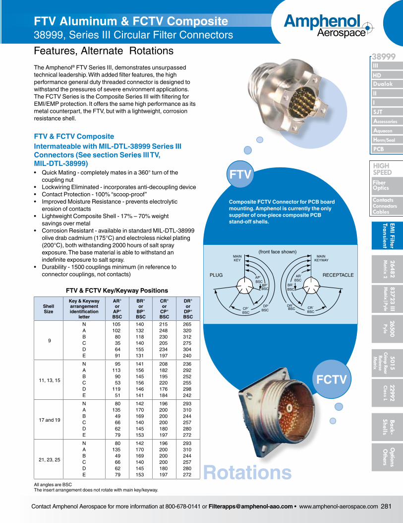
FTV Aluminum & FCTV Composite 38999, Series III Circular Filter Connectors
Features, Alternate Rotations
FTV
AP˚BSC
BP˚BSC
DP˚BSCCP˚
BSC
MAINKEY
PLUG
(front face shown)
AR˚BSC
BR˚BSC
BSCBSC CR˚
DR˚
MAINKEYWAY
RECEPTACLE
Composite FCTV Connector for PCB board mounting. Amphenol is currently the only supplier of one-piece composite PCB stand-off shells.
FCTV
The Amphenol® FTV Series III, demonstrates unsurpassed technical leadership. With added filter features, the high performance general duty threaded connector is designed to withstand the pressures of severe environment applications. The FCTV Series is the Composite Series III with filtering for EMI/EMP protection. It offers the same high performance as its metal counterpart, the FTV, but with a lightweight, corrosion resistance shell.
FTV & FCTV Composite Intermateable with MIL-DTL-38999 Series III Connectors (See section Series III TV, MIL-DTL-38999) • Quick Mating - completely mates in a 360° turn of the
cou pling nut• Lockwiring Eliminated - incorporates anti-decoupling device• Contact Protection - 100% “scoop-proof”• Improved Moisture Resistance - prevents electrolytic
erosion of contacts• Lightweight Composite Shell - 17% – 70% weight
savings over metal• Corrosion Resistant - available in standard MIL-DTL-38999
olive drab cadmium (175°C) and electroless nickel plating (200°C), both withstanding 2000 hours of salt spray expo sure. The base material is able to withstand an indefinite exposure to salt spray.
• Durability - 1500 couplings minimum (in reference to connec tor couplings, not contacts)
FTV & FCTV Key/Keyway Positions
Shell Size
Key & Keyway arrangement identification
letter
AR° or
AP° BSC
BR° or
BP° BSC
CR° or
CP° BSC
DR° or
DP° BSC
9
N A B C D E
105 102 80 35 64 91
140 132 118 140 155 131
215 248 230 205 234 197
265 320 312 275 304 240
11, 13, 15
N A B C D E
95 113 90 53
119 51
141 156 145 156 146 141
208 182 195 220 176 184
236 292 252 255 298 242
17 and 19
N A B C D E
80 135 49 66 62 79
142 170 169 140 145 153
196 200 200 200 180 197
293 310 244 257 280 272
21, 23, 25
N A B C D E
80 135 49 66 62 79
142 170 169 140 145 153
196 200 200 200 180 197
293 310 244 257 280 272
All angles are BSC The insert arrangement does not rotate with main key/keyway.
Rotations
Contact Amphenol Aerospace for more information at 800-678-0141 or [email protected] • www.amphenol-aerospace.com282
AmphenolAerospace
Dualok
III
SJT
38999
PCB
HD
EMI F
ilter
Tran
sien
t
I II
Accessories
Herm/Seal
Aquacon
Fiber Optics
ContactsConnectors
Cables
HIgH SPEED
2648
2M
atrix
2
8372
3 III
5015
2650
0 Py
le
2299
2 C
lass
L
Back
- Sh
ells
Opt
ions
O
ther
sCr
imp
Rear
Rele
ase
Mat
rix
Mat
rix|P
yle
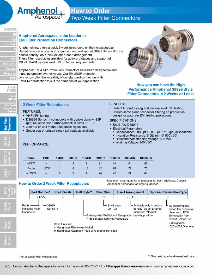
Amphenol now offers a quick 2-week turnaround on their most popular filtered receptacle connectors - jam nut and wall mount 38999 Series III in the double density -35P (pin) Mil-spec insert arrangement.These filter receptacles are ideal for quick prototypes and support of MIL-STD-461 system level EMI protection requirements.
Amphenol Aerospace is the Leader in EMI Filter Protection Connectors
Amphenol® EMI/EMP Protection Connectors have been designed in and manufactured for over 45 years. Our EMI/EMP protection connectors offer the versatility of our standard connectors with EMI/EMP protection to suit the demands of your application.
FEATURES:• VHF1 Pi filtering• D38999 Series III connectors with double density -35P
(pin) Mil-spec insert arrangement; in sizes 09 – 25• Jam nut or wall mount receptacle styles only• Solder cup or printed circuit tail contacts available
BENEFITS:• Perfect for prototyping and system level EMI testing• Utilizes same planar capacitor filtering as production
design for accurate EMI testing projections.
* For 2-Week Filter Receptacles
Part Number* Shell Finish Shell Style** Shell Size Insert Arrangement (Optional) Termination Type
21-55 4 0 09 - 35P 2
How to Order 2 Week Filter Receptacles
38999 Series III
Prefix indicates Filter Connector
Shell Finishes: 4 designates Electroless Nickel 9 designates Cadmium Plate olive drab nickel base
0 designates Wall Mount Receptacle 7 designates Jam Nut Receptacle
Shell sizes 09 – 25
Available only in double density -35 pin arrange-ment with “Normal” keyway position
By choosing this option the connector changes to PCB Termination from default Solder Cup
2 designates .020 ±.002 Diameter
Temp. FCO 1MHz 3MHz 10MHz 30MHz 100MHz 300MHz 1000MHz
–55°C – 1 2 8 21 44 61 65
Room 1.27M 1 6 18 42 62 72 75
+125°C – 0 2 9 24 45 62 64
Now you can have the High Performance Amphenol 38999 Style
Filter Connectors in 2 Weeks or Less!
PERFORMANCE:
2 Week Filter Receptacles
SPECIFICATIONS:• Shell IAW D38999• Electrical Parameters:
• Capacitance: 6,000 pf 12,000 pF “Pi” Type, all locations • Insulation Resistance: 5 GW min @ 500VDC • Dielectric Withstanding Voltage: 500 VDC • Working Voltage: 200 VDC
** See next page for dimensional data.
Maximum order quantity is 10 pieces for each shell size. Consult Amphenol Aerospace for larger quantities.
How to OrderTwo Week Filter Connectors
Contact Amphenol Aerospace for more information at 800-678-0141 or [email protected] • www.amphenol-aerospace.com 283
AmphenolAerospace
II Dualok
III
SJT
38999
I
PCB
Accessories
Aquacon
HD
EMI Filter
Transient
Herm/Seal
Fiber Optics
ContactsConnectorsCables
HIgH SPEED
26482M
atrix 2 83723 IIIM
atrix|Pyle5015
Crimp Rear
Release M
atrix
26500 Pyle
22992 C
lass L Back- Shells
Options
Others
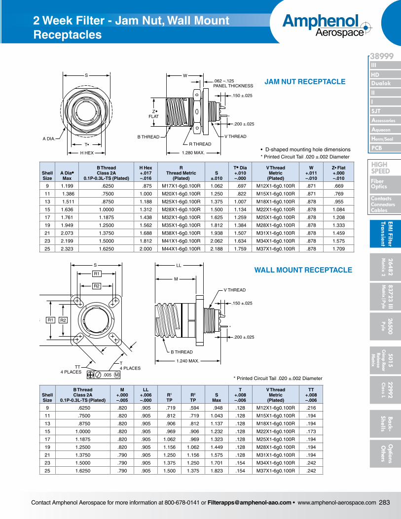
WALL MOUNT RECEPTACLE
* Printed Circuit Tail .020 ±.002 Diameter
JAM NUT RECEPTACLE
• D-shaped mounting hole dimensions* Printed Circuit Tail .020 ±.002 Diameter
Shell Size
B Thread Class 2A
0.1P-0.3L-TS (Plated)
M +.000 –.005
LL +.006 –.000
R1
TPR2
TPS
Max
T +.008 –.006
V Thread Metric
(Plated)
TT +.008 –.006
9 .6250 .820 .905 .719 .594 .948 .128 M12X1-6g0.100R .216
11 .7500 .820 .905 .812 .719 1.043 .128 M15X1-6g0.100R .194
13 .8750 .820 .905 .906 .812 1.137 .128 M18X1-6g0.100R .194
15 1.0000 .820 .905 .969 .906 1.232 .128 M22X1-6g0.100R .173
17 1.1875 .820 .905 1.062 .969 1.323 .128 M25X1-6g0.100R .194
19 1.2500 .820 .905 1.156 1.062 1.449 .128 M28X1-6g0.100R .194
21 1.3750 .790 .905 1.250 1.156 1.575 .128 M31X1-6g0.100R .194
23 1.5000 .790 .905 1.375 1.250 1.701 .154 M34X1-6g0.100R .242
25 1.6250 .790 .905 1.500 1.375 1.823 .154 M37X1-6g0.100R .242
S
R1
R2
S R1 R2
B THREAD
V THREAD
M
LL
1.240 MAX.T 4 PLACES
.005 M
TT 4 PLACES
*
.150 ±.025
.200 ±.025
S
T•
H HEX
ZFLAT
B THREAD
R THREAD
.062 –.125PANEL THICKNESS
.150 ±.025
.200 ±.025
W
1.280 MAX.
V THREAD
•
A DIA.
*
Shell Size
A Dia• Max
B Thread Class 2A
0.1P-0.3L-TS (Plated)
H Hex +.017 –.016
R Thread Metric
(Plated)S
±.010
T• Dia +.010 –.000
V Thread Metric
(Plated)
W +.011 –.010
Z• Flat +.000 –.010
9 1.199 .6250 .875 M17X1-6g0.100R 1.062 .697 M12X1-6g0.100R .871 .669
11 1.386 .7500 1.000 M20X1-6g0.100R 1.250 .822 M15X1-6g0.100R .871 .769
13 1.511 .8750 1.188 M25X1-6g0.100R 1.375 1.007 M18X1-6g0.100R .878 .955
15 1.636 1.0000 1.312 M28X1-6g0.100R 1.500 1.134 M22X1-6g0.100R .878 1.084
17 1.761 1.1875 1.438 M32X1-6g0.100R 1.625 1.259 M25X1-6g0.100R .878 1.208
19 1.949 1.2500 1.562 M35X1-6g0.100R 1.812 1.384 M28X1-6g0.100R .878 1.333
21 2.073 1.3750 1.688 M38X1-6g0.100R 1.938 1.507 M31X1-6g0.100R .878 1.459
23 2.199 1.5000 1.812 M41X1-6g0.100R 2.062 1.634 M34X1-6g0.100R .878 1.575
25 2.323 1.6250 2.000 M44X1-6g0.100R 2.188 1.759 M37X1-6g0.100R .878 1.709
2 Week Filter - Jam Nut, Wall Mount Receptacles
Contact Amphenol Aerospace for more information at 800-678-0141 or [email protected] • www.amphenol-aerospace.com284
AmphenolAerospace
Dualok
III
SJT
38999
PCB
HD
EMI F
ilter
Tran
sien
t
I II
Accessories
Herm/Seal
Aquacon
Fiber Optics
ContactsConnectors
Cables
HIgH SPEED
2648
2M
atrix
2
8372
3 III
5015
2650
0 Py
le
2299
2 C
lass
L
Back
- Sh
ells
Opt
ions
O
ther
sCr
imp
Rear
Rele
ase
Mat
rix
Mat
rix|P
yle
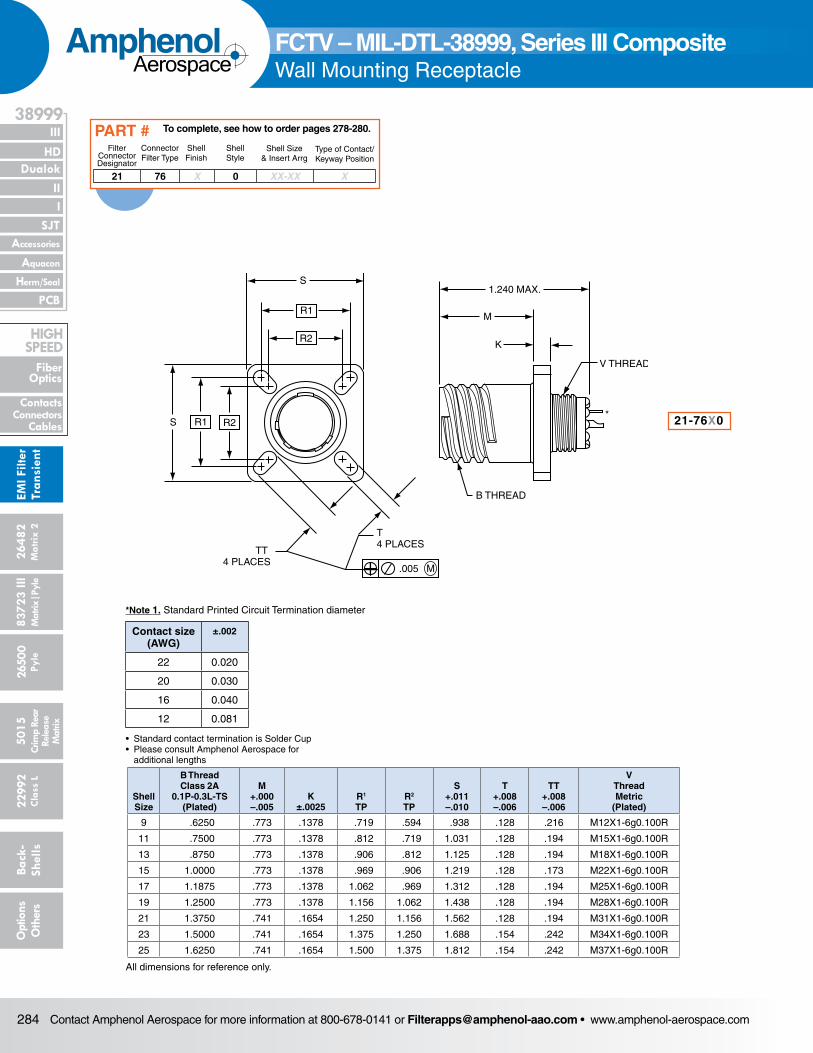
Shell Size
B Thread Class 2A
0.1P-0.3L-TS (Plated)
M +.000 –.005
K±.0025
R1
TPR2
TP
S+.011 –.010
T +.008 –.006
TT +.008 –.006
V Thread Metric
(Plated)
9 .6250 .773 .1378 .719 .594 .938 .128 .216 M12X1-6g0.100R
11 .7500 .773 .1378 .812 .719 1.031 .128 .194 M15X1-6g0.100R
13 .8750 .773 .1378 .906 .812 1.125 .128 .194 M18X1-6g0.100R
15 1.0000 .773 .1378 .969 .906 1.219 .128 .173 M22X1-6g0.100R
17 1.1875 .773 .1378 1.062 .969 1.312 .128 .194 M25X1-6g0.100R
19 1.2500 .773 .1378 1.156 1.062 1.438 .128 .194 M28X1-6g0.100R
21 1.3750 .741 .1654 1.250 1.156 1.562 .128 .194 M31X1-6g0.100R
23 1.5000 .741 .1654 1.375 1.250 1.688 .154 .242 M34X1-6g0.100R
25 1.6250 .741 .1654 1.500 1.375 1.812 .154 .242 M37X1-6g0.100R
All dimensions for reference only.
S
R1
R2
S R1 R2
B THREAD
V THREAD
K
M
1.240 MAX.
T 4 PLACES
.005 M
TT 4 PLACES
*
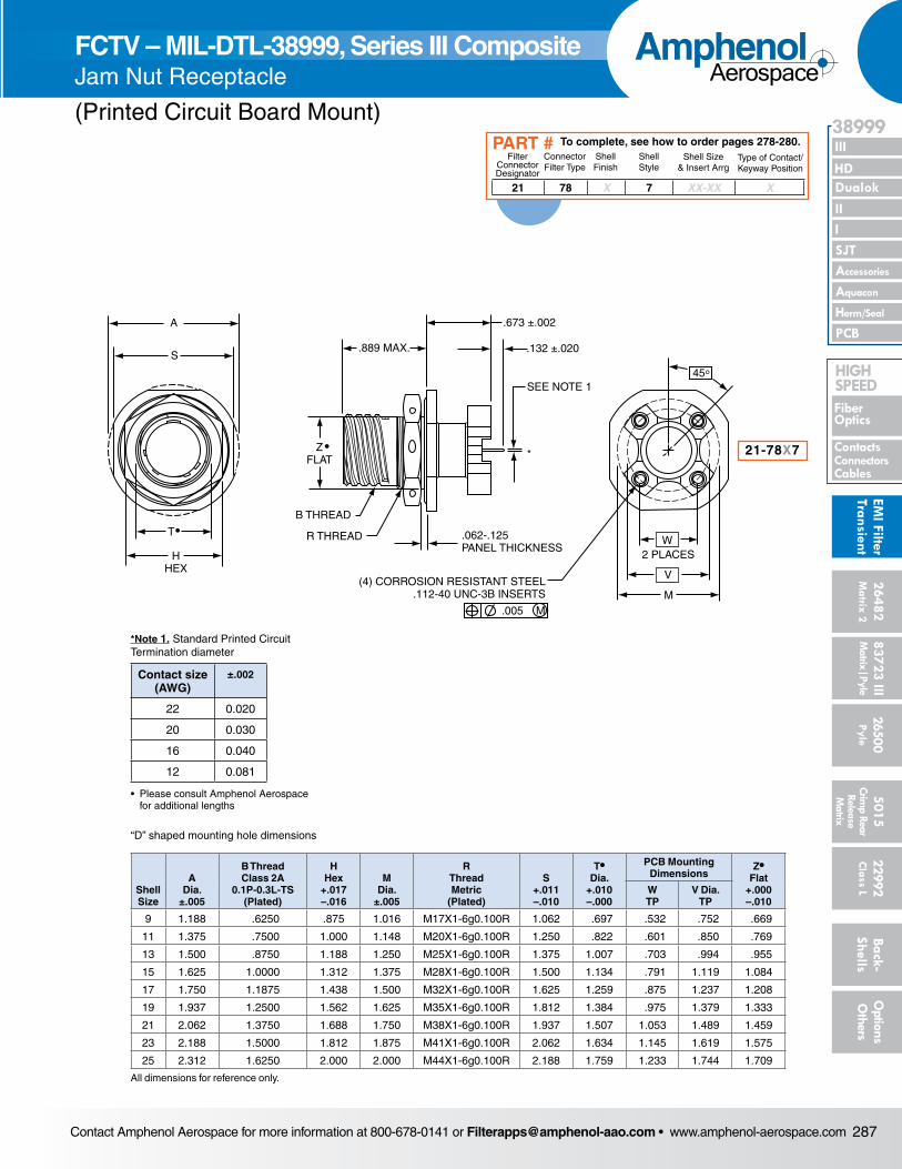
FCTV – MIL-DTL-38999, Series III CompositeWall Mounting Receptacle
21-76X0
*Note 1. Standard Printed Circuit Termination diameter
21 76 X 0 XX-XX X
Filter Connector Designator
Connector Filter Type
Shell Finish
Shell Style
Shell Size& Insert Arrg
Type of Contact/Keyway Position
To complete, see how to order pages 278-280.PART #
Contact size (AWG)
±.002
22 0.020
20 0.030
16 0.040
12 0.081
• Standard contact termination is Solder Cup• Please consult Amphenol Aerospace for additional lengths
Contact Amphenol Aerospace for more information at 800-678-0141 or [email protected] • www.amphenol-aerospace.com 285
AmphenolAerospace
II Dualok
III
SJT
38999
I
PCB
Accessories
Aquacon
HD
EMI Filter
Transient
Herm/Seal
Fiber Optics
ContactsConnectorsCables
HIgH SPEED
26482M
atrix 2 83723 IIIM
atrix|Pyle5015
Crimp Rear
Release M
atrix
26500 Pyle
22992 C
lass L Back- Shells
Options
Others
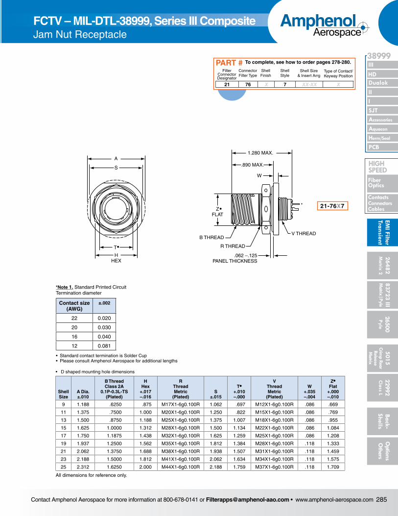
Shell Size
A Dia. ±.010
B Thread Class 2A
0.1P-0.3L-TS (Plated)
H Hex
+.017 –.016
R Thread Metric
(Plated)S
±.015
T• +.010 –.000
V Thread Metric
(Plated)
W+.035–.004
Z•Flat
+.000–.010
9 1.188 .6250 .875 M17X1-6g0.100R 1.062 .697 M12X1-6g0.100R .086 .669
11 1.375 .7500 1.000 M20X1-6g0.100R 1.250 .822 M15X1-6g0.100R .086 .769
13 1.500 .8750 1.188 M25X1-6g0.100R 1.375 1.007 M18X1-6g0.100R .086 .955
15 1.625 1.0000 1.312 M28X1-6g0.100R 1.500 1.134 M22X1-6g0.100R .086 1.084
17 1.750 1.1875 1.438 M32X1-6g0.100R 1.625 1.259 M25X1-6g0.100R .086 1.208
19 1.937 1.2500 1.562 M35X1-6g0.100R 1.812 1.384 M28X1-6g0.100R .118 1.333
21 2.062 1.3750 1.688 M38X1-6g0.100R 1.938 1.507 M31X1-6g0.100R .118 1.459
23 2.188 1.5000 1.812 M41X1-6g0.100R 2.062 1.634 M34X1-6g0.100R .118 1.575
25 2.312 1.6250 2.000 M44X1-6g0.100R 2.188 1.759 M37X1-6g0.100R .118 1.709
All dimensions for reference only.
S
A
T
HHEX
.890 MAX.
ZFLAT
B THREAD
R THREAD
.062 –.125PANEL THICKNESS
W
1.280 MAX.
V THREAD
•
•*
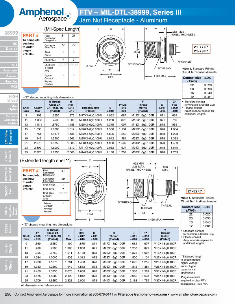
FCTV – MIL-DTL-38999, Series III Composite Jam Nut Receptacle
21 76 X 7 XX-XX X
Filter Connector Designator
Connector Filter Type
Shell Finish
Shell Style
Shell Size& Insert Arrg
Type of Contact/Keyway Position
To complete, see how to order pages 278-280.PART #
• D shaped mounting hole dimensions
21-76X7
*Note 1. Standard Printed Circuit Termination diameter
Contact size (AWG)
±.002
22 0.020
20 0.030
16 0.040
12 0.081
• Standard contact termination is Solder Cup• Please consult Amphenol Aerospace for additional lengths
Contact Amphenol Aerospace for more information at 800-678-0141 or [email protected] • www.amphenol-aerospace.com286
AmphenolAerospace
Dualok
III
SJT
38999
PCB
HD
EMI F
ilter
Tran
sien
t
I II
Accessories
Herm/Seal
Aquacon
Fiber Optics
ContactsConnectors
Cables
HIgH SPEED
2648
2M
atrix
2
8372
3 III
5015
2650
0 Py
le
2299
2 C
lass
L
Back
- Sh
ells
Opt
ions
O
ther
sCr
imp
Rear
Rele
ase
Mat
rix
Mat
rix|P
yle
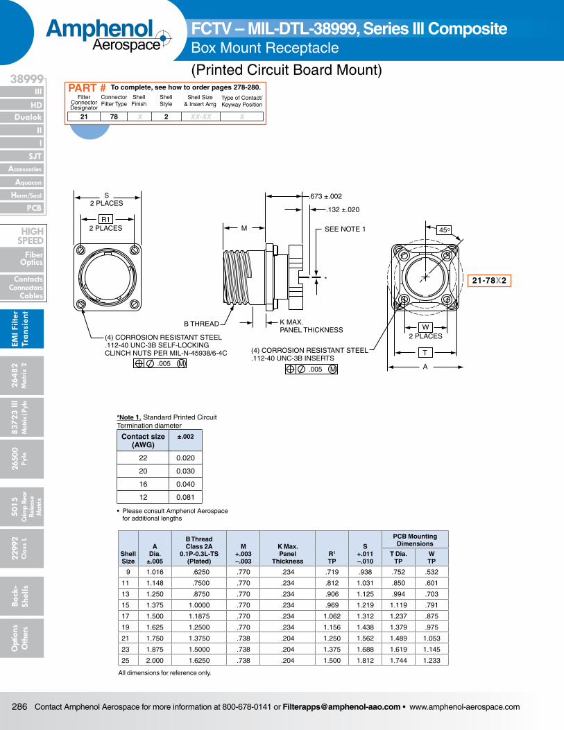
.005 M
(4) CORROSION RESISTANT STEEL.112-40 UNC-3B INSERTS
A
T
W2 PLACES
B THREAD
M
.673 ±.002
.132 ±.020
SEE NOTE 1
K MAX.PANEL THICKNESS
*
S2 PLACES
R1
.005 M
(4) CORROSION RESISTANT STEEL.112-40 UNC-3B SELF-LOCKINGCLINCH NUTS PER MIL-N-45938/6-4C
2 PLACES 45°
Shell Size
A Dia.
±.005
B Thread Class 2A
0.1P-0.3L-TS (Plated)
M +.003 –.003
K Max. Panel
ThicknessR1
TP
S +.011 –.010
PCB Mounting Dimensions
T Dia.TP
WTP
9 1.016 .6250 .770 .234 .719 .938 .752 .532
11 1.148 .7500 .770 .234 .812 1.031 .850 .601
13 1.250 .8750 .770 .234 .906 1.125 .994 .703
15 1.375 1.0000 .770 .234 .969 1.219 1.119 .791
17 1.500 1.1875 .770 .234 1.062 1.312 1.237 .875
19 1.625 1.2500 .770 .234 1.156 1.438 1.379 .975
21 1.750 1.3750 .738 .204 1.250 1.562 1.489 1.053
23 1.875 1.5000 .738 .204 1.375 1.688 1.619 1.145
25 2.000 1.6250 .738 .204 1.500 1.812 1.744 1.233
FCTV – MIL-DTL-38999, Series III CompositeBox Mount Receptacle
(Printed Circuit Board Mount)
21 78 X 2 XX-XX X
Filter Connector Designator
Connector Filter Type
Shell Finish
Shell Style
Shell Size& Insert Arrg
Type of Contact/Keyway Position
To complete, see how to order pages 278-280.PART #
21-78X2
All dimensions for reference only.
*Note 1. Standard Printed Circuit Termination diameter
Contact size (AWG)
±.002
22 0.020
20 0.030
16 0.040
12 0.081
• Please consult Amphenol Aerospace for additional lengths
Contact Amphenol Aerospace for more information at 800-678-0141 or [email protected] • www.amphenol-aerospace.com 287
AmphenolAerospace
II Dualok
III
SJT
38999
I
PCB
Accessories
Aquacon
HD
EMI Filter
Transient
Herm/Seal
Fiber Optics
ContactsConnectorsCables
HIgH SPEED
26482M
atrix 2 83723 IIIM
atrix|Pyle5015
Crimp Rear
Release M
atrix
26500 Pyle
22992 C
lass L Back- Shells
Options
Others
FCTV – MIL-DTL-38999, Series III CompositeBox Mount Receptacle
(Printed Circuit Board Mount)
S
A
HHEX
.673 ±.002
.132 ±.020
SEE NOTE 1
W
V
M
.889 MAX.
B THREAD
R THREAD .062-.125PANEL THICKNESS
(4) CORROSION RESISTANT STEEL.112-40 UNC-3B INSERTS
.005 M
2 PLACES
T•
ZFLAT
•
45°
*
Shell Size
A Dia.
±.005
B Thread Class 2A
0.1P-0.3L-TS (Plated)
H Hex
+.017–.016
M Dia.
±.005
R ThreadMetric
(Plated)
S+.011 –.010
T• Dia.
+.010–.000
PCB Mounting Dimensions
Z• Flat
+.000–.010
WTP
V Dia.TP
9 1.188 .6250 .875 1.016 M17X1-6g0.100R 1.062 .697 .532 .752 .669
11 1.375 .7500 1.000 1.148 M20X1-6g0.100R 1.250 .822 .601 .850 .769
13 1.500 .8750 1.188 1.250 M25X1-6g0.100R 1.375 1.007 .703 .994 .955
15 1.625 1.0000 1.312 1.375 M28X1-6g0.100R 1.500 1.134 .791 1.119 1.084
17 1.750 1.1875 1.438 1.500 M32X1-6g0.100R 1.625 1.259 .875 1.237 1.208
19 1.937 1.2500 1.562 1.625 M35X1-6g0.100R 1.812 1.384 .975 1.379 1.333
21 2.062 1.3750 1.688 1.750 M38X1-6g0.100R 1.937 1.507 1.053 1.489 1.459
23 2.188 1.5000 1.812 1.875 M41X1-6g0.100R 2.062 1.634 1.145 1.619 1.575
25 2.312 1.6250 2.000 2.000 M44X1-6g0.100R 2.188 1.759 1.233 1.744 1.709
All dimensions for reference only.
FCTV – MIL-DTL-38999, Series III Composite Jam Nut Receptacle
(Printed Circuit Board Mount)
21-78X7
“D” shaped mounting hole dimensions
21 78 X 7 XX-XX X
Filter Connector Designator
Connector Filter Type
Shell Finish
Shell Style
Shell Size& Insert Arrg
Type of Contact/Keyway Position
To complete, see how to order pages 278-280.PART #
*Note 1. Standard Printed Circuit Termination diameter
Contact size (AWG)
±.002
22 0.020
20 0.030
16 0.040
12 0.081
• Please consult Amphenol Aerospace for additional lengths
Contact Amphenol Aerospace for more information at 800-678-0141 or [email protected] • www.amphenol-aerospace.com288
AmphenolAerospace
Dualok
III
SJT
38999
PCB
HD
EMI F
ilter
Tran
sien
t
I II
Accessories
Herm/Seal
Aquacon
Fiber Optics
ContactsConnectors
Cables
HIgH SPEED
2648
2M
atrix
2
8372
3 III
5015
2650
0 Py
le
2299
2 C
lass
L
Back
- Sh
ells
Opt
ions
O
ther
sCr
imp
Rear
Rele
ase
Mat
rix
Mat
rix|P
yle
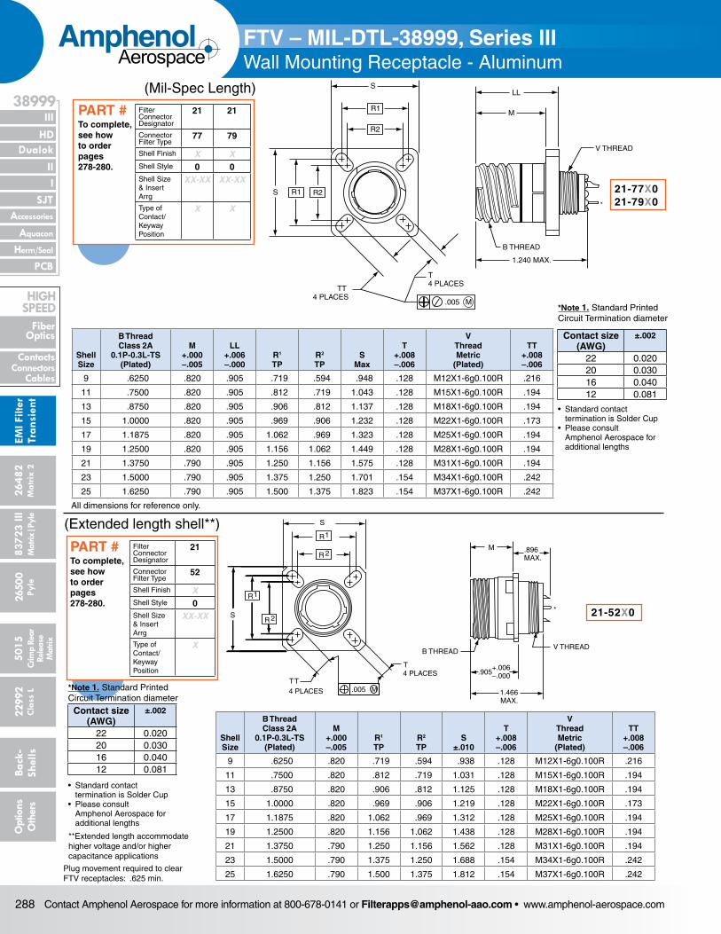
FTV – MIL-DTL-38999, Series IIIWall Mounting Receptacle - Aluminum
Shell Size
B Thread Class 2A
0.1P-0.3L-TS (Plated)
M +.000 –.005
LL +.006 –.000
R1
TPR2
TPS
Max
T +.008 –.006
V Thread Metric
(Plated)
TT +.008 –.006
9 .6250 .820 .905 .719 .594 .948 .128 M12X1-6g0.100R .216
11 .7500 .820 .905 .812 .719 1.043 .128 M15X1-6g0.100R .194
13 .8750 .820 .905 .906 .812 1.137 .128 M18X1-6g0.100R .194
15 1.0000 .820 .905 .969 .906 1.232 .128 M22X1-6g0.100R .173
17 1.1875 .820 .905 1.062 .969 1.323 .128 M25X1-6g0.100R .194
19 1.2500 .820 .905 1.156 1.062 1.449 .128 M28X1-6g0.100R .194
21 1.3750 .790 .905 1.250 1.156 1.575 .128 M31X1-6g0.100R .194
23 1.5000 .790 .905 1.375 1.250 1.701 .154 M34X1-6g0.100R .242
25 1.6250 .790 .905 1.500 1.375 1.823 .154 M37X1-6g0.100R .242
S
R1
R2
S R1 R2
B THREAD
V THREAD
M
LL
1.240 MAX.
T 4 PLACES
.005 M
TT 4 PLACES
*
All dimensions for reference only.
Shell Size
B Thread Class 2A
0.1P-0.3L-TS (Plated)
M +.000 –.005
R1
TPR2
TPS
±.010
T +.008 –.006
V Thread Metric
(Plated)
TT +.008 –.006
9 .6250 .820 .719 .594 .938 .128 M12X1-6g0.100R .216
11 .7500 .820 .812 .719 1.031 .128 M15X1-6g0.100R .194
13 .8750 .820 .906 .812 1.125 .128 M18X1-6g0.100R .194
15 1.0000 .820 .969 .906 1.219 .128 M22X1-6g0.100R .173
17 1.1875 .820 1.062 .969 1.312 .128 M25X1-6g0.100R .194
19 1.2500 .820 1.156 1.062 1.438 .128 M28X1-6g0.100R .194
21 1.3750 .790 1.250 1.156 1.562 .128 M31X1-6g0.100R .194
23 1.5000 .790 1.375 1.250 1.688 .154 M34X1-6g0.100R .242
25 1.6250 .790 1.500 1.375 1.812 .154 M37X1-6g0.100R .242
S
R
R
1
2
R1
R 2S
4 PLACESTT
T4 PLACES
.005 M
M .896MAX.
B THREADV THREAD
.905
1.466MAX.
+.006–.000
*
21-77X021-79X0
21-52X0
To complete, see how to order pages 278-280.
PART # Filter Connector Designator
21 21
Connector Filter Type
77 79
Shell Finish X XShell Style 0 0Shell Size& Insert Arrg
XX-XX XX-XX
Type of Contact/Keyway Position
X X
(Mil-Spec Length)
Plug movement required to clear FTV receptacles: .625 min.
(Extended length shell**)
**Extended length accommodate higher voltage and/or higher capacitance applications
To complete, see how to order pages 278-280.
PART # Filter Connector Designator
21
Connector Filter Type
52
Shell Finish XShell Style 0Shell Size& Insert Arrg
XX-XX
Type of Contact/Keyway Position
X
Contact size (AWG)
±.002
22 0.02020 0.03016 0.04012 0.081
*Note 1. Standard Printed Circuit Termination diameter
• Standard contact termination is Solder Cup• Please consult Amphenol Aerospace for additional lengths
Contact size (AWG)
±.002
22 0.02020 0.03016 0.04012 0.081
*Note 1. Standard Printed Circuit Termination diameter
• Standard contact termination is Solder Cup• Please consult Amphenol Aerospace for additional lengths
Contact Amphenol Aerospace for more information at 800-678-0141 or [email protected] • www.amphenol-aerospace.com 289
AmphenolAerospace
II Dualok
III
SJT
38999
I
PCB
Accessories
Aquacon
HD
EMI Filter
Transient
Herm/Seal
Fiber Optics
ContactsConnectorsCables
HIgH SPEED
26482M
atrix 2 83723 IIIM
atrix|Pyle5015
Crimp Rear
Release M
atrix
26500 Pyle
22992 C
lass L Back- Shells
Options
Others
Shell Size
B Thread Class 2A
0.1P-0.3L-TS (Plated)
E +.000 –.005
R1
TPR2
TPS
±.010
T +.008 –.006
V Thread Metric
(Plated)
TT +.008 –.006
9 .6250 .820 .719 .594 .938 .128 M15X1-6g0.100R .216
11 .7500 .820 .812 .719 1.031 .128 M18X1-6g0.100R .194
13 .8750 .820 .906 .812 1.125 .128 M22X1-6g0.100R .194
15 1.0000 .820 .969 .906 1.219 .128 M25X1-6g0.100R .173
17 1.1875 .820 1.062 .969 1.312 .128 M28X1-6g0.100R .194
19 1.2500 .820 1.156 1.062 1.438 .128 M31X1-6g0.100R .194
21 1.3750 .790 1.250 1.156 1.562 .128 M34X1-6g0.100R .194
23 1.5000 .790 1.375 1.250 1.688 .154 M37X1-6g0.100R .242
25 1.6250 .790 1.500 1.375 1.812 .154 M41X1-6g0.100R .242
All dimensions for reference only.
S
R
R
1
2
R1
R 2S
4 PLACESTT
T4 PLACES
.005 M
B THREAD
E
+.006–.000.905
V THREAD
1.922 MAX.
.100MAX.
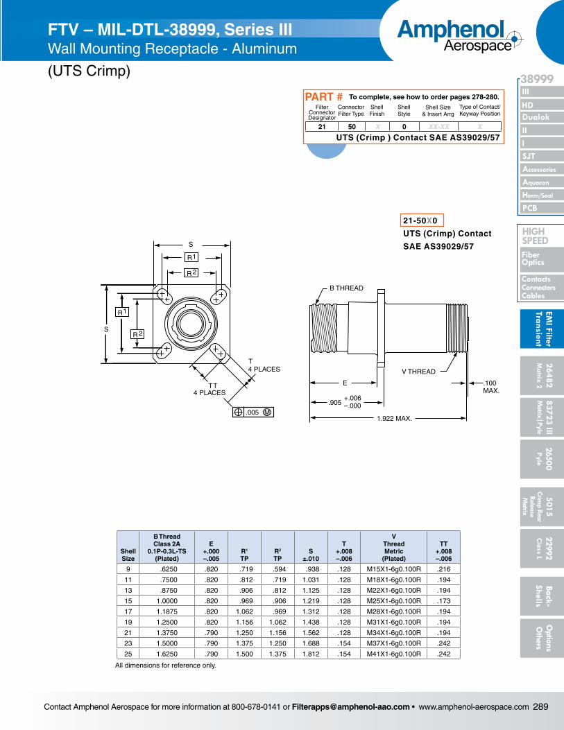
FTV – MIL-DTL-38999, Series IIIWall Mounting Receptacle - Aluminum
(UTS Crimp)
21-50X0
UTS (Crimp) Contact
SAE AS39029/57
21 50 X 0 XX-XX X
Filter Connector Designator
Connector Filter Type
Shell Finish
Shell Style
Shell Size& Insert Arrg
Type of Contact/Keyway Position
To complete, see how to order pages 278-280.PART #
UTS (Crimp ) Contact SAE AS39029/57
Contact Amphenol Aerospace for more information at 800-678-0141 or [email protected] • www.amphenol-aerospace.com290
AmphenolAerospace
Dualok
III
SJT
38999
PCB
HD
EMI F
ilter
Tran
sien
t
I II
Accessories
Herm/Seal
Aquacon
Fiber Optics
ContactsConnectors
Cables
HIgH SPEED
2648
2M
atrix
2
8372
3 III
5015
2650
0 Py
le
2299
2 C
lass
L
Back
- Sh
ells
Opt
ions
O
ther
sCr
imp
Rear
Rele
ase
Mat
rix
Mat
rix|P
yle
Shell Size
A Dia• Max
B Thread Class 2A
0.1P-0.3L-TS (Plated)
H Hex
+.017 –.016
R Thread Metric
(Plated)S
±.010
T• Dia +.010 –.000
V Thread Metric
(Plated)
W +.011 –.010
Z• Flat
+.000 –.010
9 1.199 .6250 .875 M17X1-6g0.100R 1.062 .697 M12X1-6g0.100R .871 .669
11 1.386 .7500 1.000 M20X1-6g0.100R 1.250 .822 M15X1-6g0.100R .871 .769
13 1.511 .8750 1.188 M25X1-6g0.100R 1.375 1.007 M18X1-6g0.100R .878 .955
15 1.636 1.0000 1.312 M28X1-6g0.100R 1.500 1.134 M22X1-6g0.100R .878 1.084
17 1.761 1.1875 1.438 M32X1-6g0.100R 1.625 1.259 M25X1-6g0.100R .878 1.208
19 1.949 1.2500 1.562 M35X1-6g0.100R 1.812 1.384 M28X1-6g0.100R .878 1.333
21 2.073 1.3750 1.688 M38X1-6g0.100R 1.938 1.507 M31X1-6g0.100R .878 1.459
23 2.199 1.5000 1.812 M41X1-6g0.100R 2.062 1.634 M34X1-6g0.100R .878 1.575
25 2.323 1.6250 2.000 M44X1-6g0.100R 2.188 1.759 M37X1-6g0.100R .878 1.709
S
T•
HHEX
ZFLAT
B THREAD
R THREAD
.062 –.125PANEL THICKNESS
W
1.280 MAX.
V THREAD
•
A Dia.
*
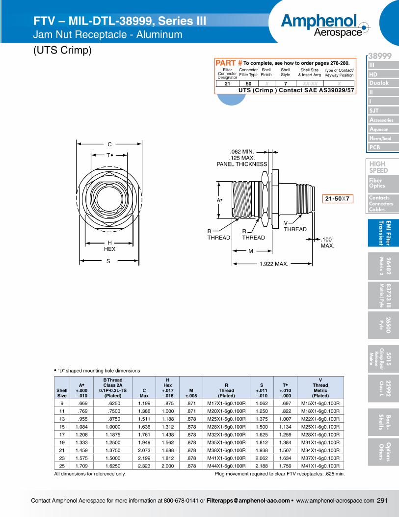
FTV – MIL-DTL-38999, Series IIIJam Nut Receptacle - Aluminum
Shell Size
A• +.000 –.010
B Thread Class 2A
0.1P-0.3L-TS (Plated)
C Max
H Hex
+.017 –.016
M +.011 –.010
R Thread (Plated)
S +.011 –.010
T• +.010 –.000
V Thread Metric
(Plated)
9 .669 .6250 1.199 .875 .871 M17X1-6g0.100R 1.062 .697 M12X1-6g0.100R
11 .769 .7500 1.386 1.000 .871 M20X1-6g0.100R 1.250 .822 M15X1-6g0.100R
13 .955 .8750 1.511 1.188 .878 M25X1-6g0.100R 1.375 1.007 M18X1-6g0.100R
15 1.084 1.0000 1.636 1.312 .878 M28X1-6g0.100R 1.500 1.134 M22X1-6g0.100R
17 1.208 1.1875 1.761 1.438 .878 M32X1-6g0.100R 1.625 1.259 M25X1-6g0.100R
19 1.333 1.2500 1.949 1.562 .878 M35X1-6g0.100R 1.812 1.384 M28X1-6g0.100R
21 1.459 1.3750 2.073 1.688 .878 M38X1-6g0.100R 1.938 1.507 M31X1-6g0.100R
23 1.575 1.5000 2.199 1.812 .878 M41X1-6g0.100R 2.062 1.634 M34X1-6g0.100R
25 1.709 1.6250 2.323 2.000 .878 M44X1-6g0.100R 2.188 1.759 M37X1-6g0.100R
All dimensions for reference only.
**Extended length to accommodate higher voltage and/or higher capacitance applications
21-77X721-79X7
C
T•
HHEX
S
A•
.062 MIN..125 MAX.
PANEL THICKNESS
B THREADRTHREAD
M
VTHREAD
.976MAX.
1.466 MAX.
* 21-52X7
C
T•
HHEX
S
A•
.062 MIN..125 MAX.
PANEL THICKNESS
B THREADRTHREAD
M
VTHREAD
.976MAX.
1.466 MAX.
*
Plug movement required to clear FTV receptacles: .625 min.
S
T•
HHEX
ZFLAT
B THREAD
R THREAD
.062 –.125PANEL THICKNESS
W
1.280 MAX.
V THREAD
•
A Dia.
*
To complete, see how to order pages 278-280.
PART # Filter Connector Designator
21 21
Connector Filter Type
77 79
Shell Finish
X X
Shell Style 7 7
Shell Size& Insert Arrg
XX-XX XX-XX
Type of Contact/Keyway Position
X X
(Mil-Spec Length)
To complete, see how to order pages 278-280.
PART # Filter Connector Designator
21
Connector Filter Type
52
Shell Finish XShell Style 7Shell Size& Insert Arrg
XX-XX
Type of Contact/Keyway Position
X
(Extended length shell**)
Contact size (AWG)
±.002
22 0.02020 0.03016 0.04012 0.081
*Note 1. Standard Printed Circuit Termination diameter
• Standard contact termination is Solder Cup• Please consult Amphenol Aerospace for additional lengths
Contact size (AWG)
±.002
22 0.02020 0.03016 0.04012 0.081
*Note 1. Standard Printed Circuit Termination diameter
• Standard contact termination is Solder Cup• Please consult Amphenol Aerospace for additional lengths
• “D” shaped mounting hole dimensions
• “D” shaped mounting hole dimensions
Contact Amphenol Aerospace for more information at 800-678-0141 or [email protected] • www.amphenol-aerospace.com 291
AmphenolAerospace
II Dualok
III
SJT
38999
I
PCB
Accessories
Aquacon
HD
EMI Filter
Transient
Herm/Seal
Fiber Optics
ContactsConnectorsCables
HIgH SPEED
26482M
atrix 2 83723 IIIM
atrix|Pyle5015
Crimp Rear
Release M
atrix
26500 Pyle
22992 C
lass L Back- Shells
Options
Others
• “D” shaped mounting hole dimensions
Shell Size
A• +.000 –.010
B Thread Class 2A
0.1P-0.3L-TS (Plated)
C Max
H Hex
+.017 –.016
M ±.005
R Thread (Plated)
S +.011 –.010
T• +.010 –.000
V Thread Metric
(Plated)
9 .669 .6250 1.199 .875 .871 M17X1-6g0.100R 1.062 .697 M15X1-6g0.100R
11 .769 .7500 1.386 1.000 .871 M20X1-6g0.100R 1.250 .822 M18X1-6g0.100R
13 .955 .8750 1.511 1.188 .878 M25X1-6g0.100R 1.375 1.007 M22X1-6g0.100R
15 1.084 1.0000 1.636 1.312 .878 M28X1-6g0.100R 1.500 1.134 M25X1-6g0.100R
17 1.208 1.1875 1.761 1.438 .878 M32X1-6g0.100R 1.625 1.259 M28X1-6g0.100R
19 1.333 1.2500 1.949 1.562 .878 M35X1-6g0.100R 1.812 1.384 M31X1-6g0.100R
21 1.459 1.3750 2.073 1.688 .878 M38X1-6g0.100R 1.938 1.507 M34X1-6g0.100R
23 1.575 1.5000 2.199 1.812 .878 M41X1-6g0.100R 2.062 1.634 M37X1-6g0.100R
25 1.709 1.6250 2.323 2.000 .878 M44X1-6g0.100R 2.188 1.759 M41X1-6g0.100R
All dimensions for reference only.
C
HHEX
S
T•
A
.062 MIN..125 MAX.
PANEL THICKNESS
BTHREAD
RTHREAD
M
1.922 MAX.
VTHREAD
.100MAX.
•
FTV – MIL-DTL-38999, Series IIIJam Nut Receptacle - Aluminum
(UTS Crimp)
21-50X7
Plug movement required to clear FTV receptacles: .625 min.
21 50 X 7 XX-XX X
Filter Connector Designator
Connector Filter Type
Shell Finish
Shell Style
Shell Size& Insert Arrg
Type of Contact/Keyway Position
To complete, see how to order pages 278-280.PART #
UTS (Crimp ) Contact SAE AS39029/57
Contact Amphenol Aerospace for more information at 800-678-0141 or [email protected] • www.amphenol-aerospace.com292
AmphenolAerospace
Dualok
III
SJT
38999
PCB
HD
EMI F
ilter
Tran
sien
t
I II
Accessories
Herm/Seal
Aquacon
Fiber Optics
ContactsConnectors
Cables
HIgH SPEED
2648
2M
atrix
2
8372
3 III
5015
2650
0 Py
le
2299
2 C
lass
L
Back
- Sh
ells
Opt
ions
O
ther
sCr
imp
Rear
Rele
ase
Mat
rix
Mat
rix|P
yle
R1
S
(4) CORROSIONRESISTANT STEEL.112-40 UNC-3B CLINCH NUTS
.005 M
B THREAD
K 45°
V
W2 PLACES
J
.673 ±.002
.132 ±.020
.830±.005
SEE NOTE 1
(4) CORROSION RESISTANT STEEL HELICAL COIL WITH LOCKING THREADS
.112-40 UNC-3B INSERTS.005 M
*
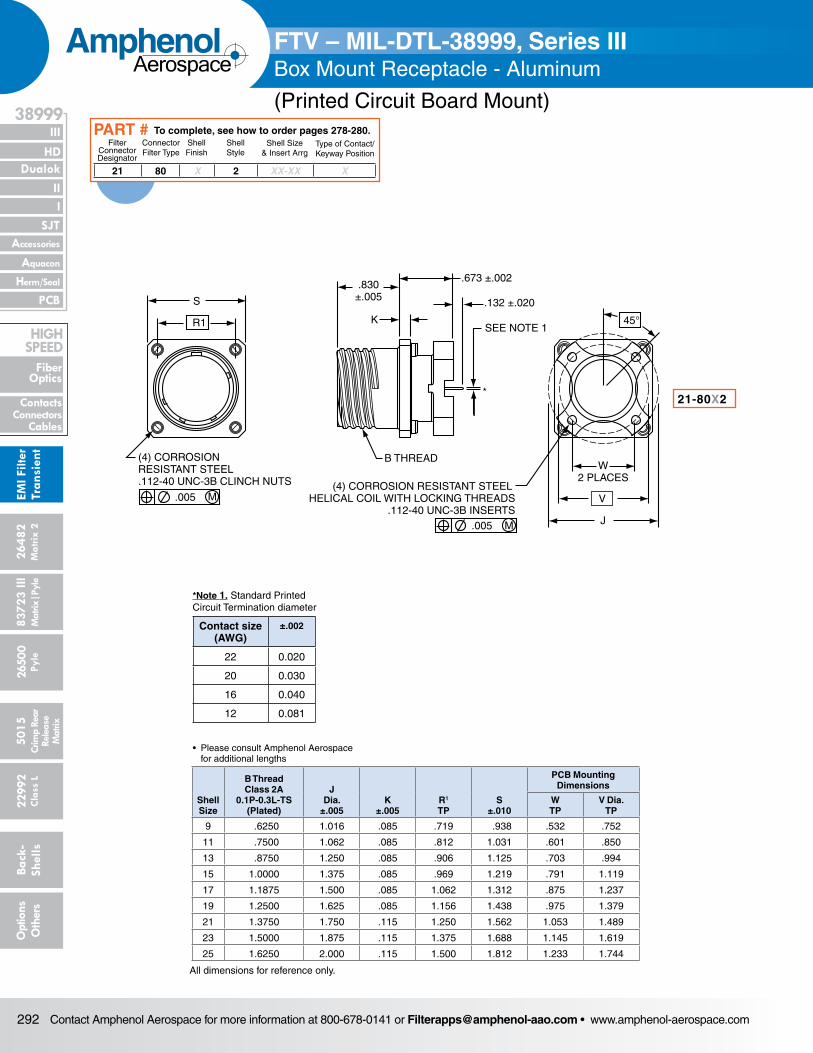
Shell Size
B Thread Class 2A
0.1P-0.3L-TS (Plated)
J Dia.
±.005K
±.005R1
TPS
±.010
PCB Mounting Dimensions
WTP
V Dia.TP
9 .6250 1.016 .085 .719 .938 .532 .752
11 .7500 1.062 .085 .812 1.031 .601 .850
13 .8750 1.250 .085 .906 1.125 .703 .994
15 1.0000 1.375 .085 .969 1.219 .791 1.119
17 1.1875 1.500 .085 1.062 1.312 .875 1.237
19 1.2500 1.625 .085 1.156 1.438 .975 1.379
21 1.3750 1.750 .115 1.250 1.562 1.053 1.489
23 1.5000 1.875 .115 1.375 1.688 1.145 1.619
25 1.6250 2.000 .115 1.500 1.812 1.233 1.744
FTV – MIL-DTL-38999, Series III Box Mount Receptacle - Aluminum
(Printed Circuit Board Mount)
21 80 X 2 XX-XX X
Filter Connector Designator
Connector Filter Type
Shell Finish
Shell Style
Shell Size& Insert Arrg
Type of Contact/Keyway Position
To complete, see how to order pages 278-280.PART #
All dimensions for reference only.
21-80X2
*Note 1. Standard Printed Circuit Termination diameter
Contact size (AWG)
±.002
22 0.020
20 0.030
16 0.040
12 0.081
• Please consult Amphenol Aerospace for additional lengths
Contact Amphenol Aerospace for more information at 800-678-0141 or [email protected] • www.amphenol-aerospace.com 293
AmphenolAerospace
II Dualok
III
SJT
38999
I
PCB
Accessories
Aquacon
HD
EMI Filter
Transient
Herm/Seal
Fiber Optics
ContactsConnectorsCables
HIgH SPEED
26482M
atrix 2 83723 IIIM
atrix|Pyle5015
Crimp Rear
Release M
atrix
26500 Pyle
22992 C
lass L Back- Shells
Options
Others
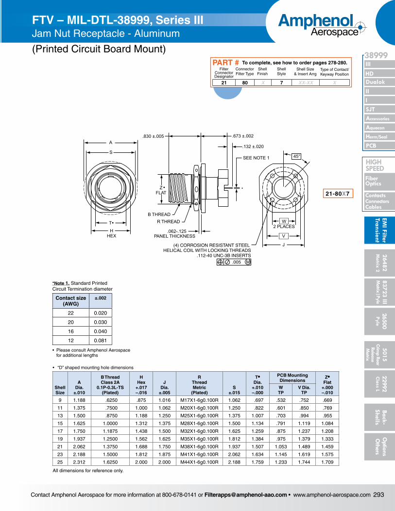
• Please consult Amphenol Aerospace for additional lengths
Shell Size
A Dia.
±.010
B Thread Class 2A
0.1P-0.3L-TS (Plated)
H Hex
+.017–.016
J Dia.
±.005
R ThreadMetric
(Plated)S
±.015
T• Dia.
+.010–.000
PCB Mounting Dimensions
Z• Flat
+.000–.010
WTP
V Dia.TP
9 1.188 .6250 .875 1.016 M17X1-6g0.100R 1.062 .697 .532 .752 .669
11 1.375 .7500 1.000 1.062 M20X1-6g0.100R 1.250 .822 .601 .850 .769
13 1.500 .8750 1.188 1.250 M25X1-6g0.100R 1.375 1.007 .703 .994 .955
15 1.625 1.0000 1.312 1.375 M28X1-6g0.100R 1.500 1.134 .791 1.119 1.084
17 1.750 1.1875 1.438 1.500 M32X1-6g0.100R 1.625 1.259 .875 1.237 1.208
19 1.937 1.2500 1.562 1.625 M35X1-6g0.100R 1.812 1.384 .975 1.379 1.333
21 2.062 1.3750 1.688 1.750 M38X1-6g0.100R 1.937 1.507 1.053 1.489 1.459
23 2.188 1.5000 1.812 1.875 M41X1-6g0.100R 2.062 1.634 1.145 1.619 1.575
25 2.312 1.6250 2.000 2.000 M44X1-6g0.100R 2.188 1.759 1.233 1.744 1.709
S
A
HHEX
.673 ±.002
.132 ±.020
SEE NOTE 1 45°
W2 PLACES
V
J
.830 ±.005
B THREADR THREAD
.062-.125PANEL THICKNESS
T•
ZFLAT
•
(4) CORROSION RESISTANT STEEL HELICAL COIL WITH LOCKING THREADS
.112-40 UNC-3B INSERTS.005 M
*
FTV – MIL-DTL-38999, Series III Jam Nut Receptacle - Aluminum
(Printed Circuit Board Mount)
21-80X7
All dimensions for reference only.
• “D” shaped mounting hole dimensions
21 80 X 7 XX-XX X
Filter Connector Designator
Connector Filter Type
Shell Finish
Shell Style
Shell Size& Insert Arrg
Type of Contact/Keyway Position
To complete, see how to order pages 278-280.PART #
*Note 1. Standard Printed Circuit Termination diameter
Contact size (AWG)
±.002
22 0.020
20 0.030
16 0.040
12 0.081
Contact Amphenol Aerospace for more information at 800-678-0141 or [email protected] • www.amphenol-aerospace.com294
AmphenolAerospace
Dualok
III
SJT
38999
PCB
HD
EMI F
ilter
Tran
sien
t
I II
Accessories
Herm/Seal
Aquacon
Fiber Optics
ContactsConnectors
Cables
HIgH SPEED
2648
2M
atrix
2
8372
3 III
5015
2650
0 Py
le
2299
2 C
lass
L
Back
- Sh
ells
Opt
ions
O
ther
sCr
imp
Rear
Rele
ase
Mat
rix
Mat
rix|P
yle
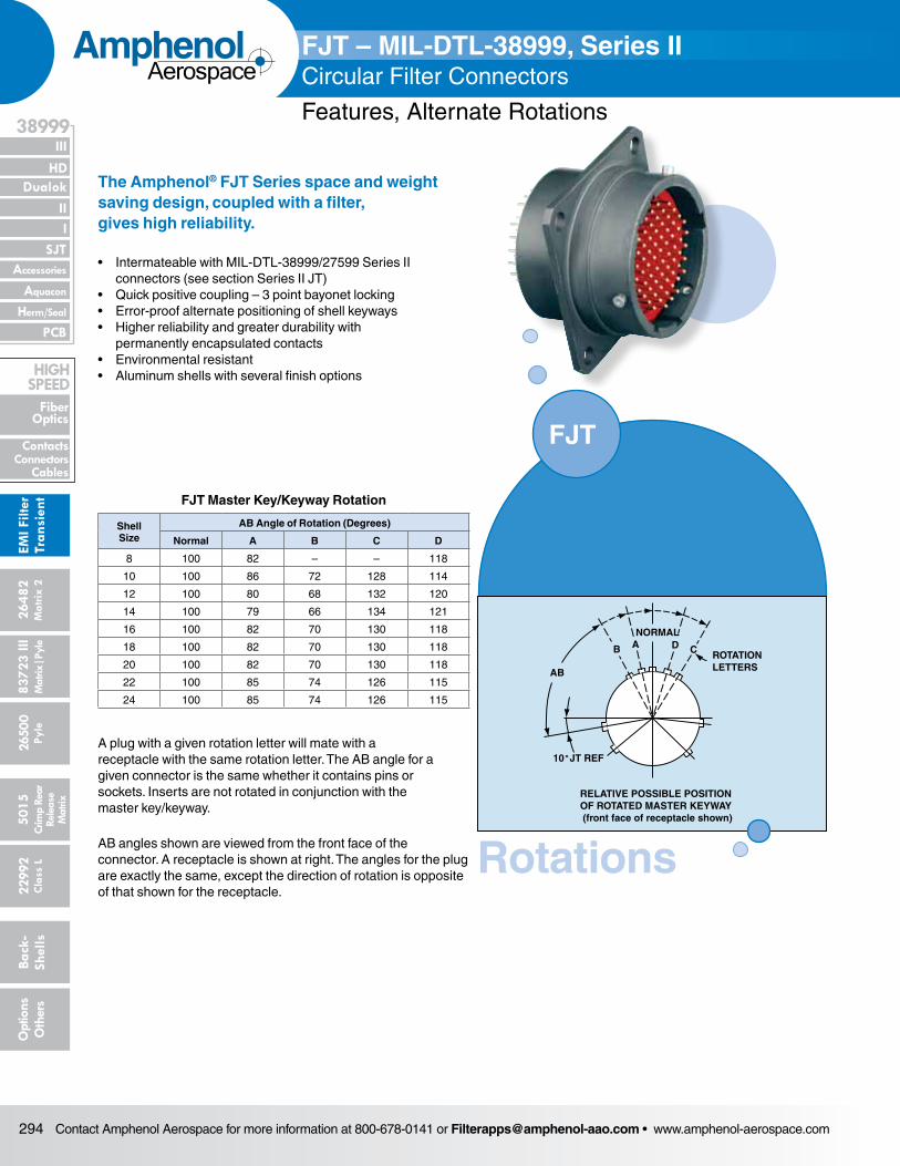
The Amphenol® FJT Series space and weight saving design, coupled with a filter, gives high reliability.
• Intermateable with MIL-DTL-38999/27599 Series II connec tors (see section Series II JT)
• Quick positive coupling – 3 point bayonet locking• Error-proof alternate positioning of shell keyways• Higher reliability and greater durability with
permanently encapsulated contacts• Environmental resistant• Aluminum shells with several finish options
FJT Master Key/Keyway Rotation
Shell Size
AB Angle of Rotation (Degrees)
Normal A B C D
8 100 82 – – 118
10 100 86 72 128 114
12 100 80 68 132 120
14 100 79 66 134 121
16 100 82 70 130 118
18 100 82 70 130 118
20 100 82 70 130 118
22 100 85 74 126 115
24 100 85 74 126 115
A plug with a given rotation letter will mate with a receptacle with the same rotation letter. The AB angle for a given connec tor is the same whether it contains pins or sockets. Inserts are not rotated in conjunction with the master key/keyway.
AB angles shown are viewed from the front face of the connec tor. A receptacle is shown at right. The angles for the plug are exactly the same, except the direction of rotation is opposite of that shown for the receptacle.
ROTATIONLETTERS
NORMAL
B A D C
AB
10 JT REF
RELATIVE POSSIBLE POSITIONOF ROTATED MASTER KEYWAY (front face of receptacle shown)
˚
FJT – MIL-DTL-38999, Series IICircular Filter Connectors
Features, Alternate Rotations
FJT
Rotations
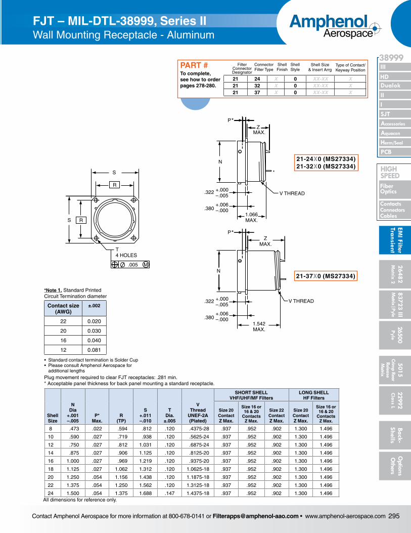
Contact Amphenol Aerospace for more information at 800-678-0141 or [email protected] • www.amphenol-aerospace.com 295
AmphenolAerospace
II Dualok
III
SJT
38999
I
PCB
Accessories
Aquacon
HD
EMI Filter
Transient
Herm/Seal
Fiber Optics
ContactsConnectorsCables
HIgH SPEED
26482M
atrix 2 83723 IIIM
atrix|Pyle5015
Crimp Rear
Release M
atrix
26500 Pyle
22992 C
lass L Back- Shells
Options
Others
S
R
RS
.005 M
T4 HOLES
V THREAD.322 +.000–.005
+.006–.000
1.066MAX.
.380
.322 +.000–.005
+.006–.000.380
N
ZMAX.
P*
ZMAX.
N
P*
V THREAD
1.542MAX.
*
Plug movement required to clear FJT receptacles: .281 min.* Acceptable panel thickness for back panel mounting a standard receptacle.
Shell Size
N Dia
+.001 –.005
P* Max.
R (TP)
S +.011 –.010
T Dia.
±.005
V Thread
UNEF-2A (Plated)
SHORT SHELL VHF/UHF/MF Filters
LONG SHELL HF Filters
Size 20 Contact Z Max.
Size 16 or 16 & 20
Contacts Z Max.
Size 22 Contact Z Max.
Size 20 Contact Z Max.
Size 16 or 16 & 20
Contacts Z Max.
8 .473 .022 .594 .812 .120 .4375-28 .937 .952 .902 1.300 1.496
10 .590 .027 .719 .938 .120 .5625-24 .937 .952 .902 1.300 1.496
12 .750 .027 .812 1.031 .120 .6875-24 .937 .952 .902 1.300 1.496
14 .875 .027 .906 1.125 .120 .8125-20 .937 .952 .902 1.300 1.496
16 1.000 .027 .969 1.219 .120 .9375-20 .937 .952 .902 1.300 1.496
18 1.125 .027 1.062 1.312 .120 1.0625-18 .937 .952 .902 1.300 1.496
20 1.250 .054 1.156 1.438 .120 1.1875-18 .937 .952 .902 1.300 1.496
22 1.375 .054 1.250 1.562 .120 1.3125-18 .937 .952 .902 1.300 1.496
24 1.500 .054 1.375 1.688 .147 1.4375-18 .937 .952 .902 1.300 1.496All dimensions for reference only.
21-24X0 (MS27334)21-32X0 (MS27334)
21-37X0 (MS27334)
FJT – MIL-DTL-38999, Series IIWall Mounting Receptacle - Aluminum
21 24 X 0 XX-XX X21 32 X 0 XX-XX X21 37 X 0 XX-XX X
Filter Connector Designator
Connector Filter Type
Shell Finish
Shell Style
Shell Size& Insert Arrg
Type of Contact/Keyway Position
To complete, see how to order pages 278-280.
PART #
*Note 1. Standard Printed Circuit Termination diameter
Contact size (AWG)
±.002
22 0.020
20 0.030
16 0.040
12 0.081
• Standard contact termination is Solder Cup• Please consult Amphenol Aerospace for additional lengths
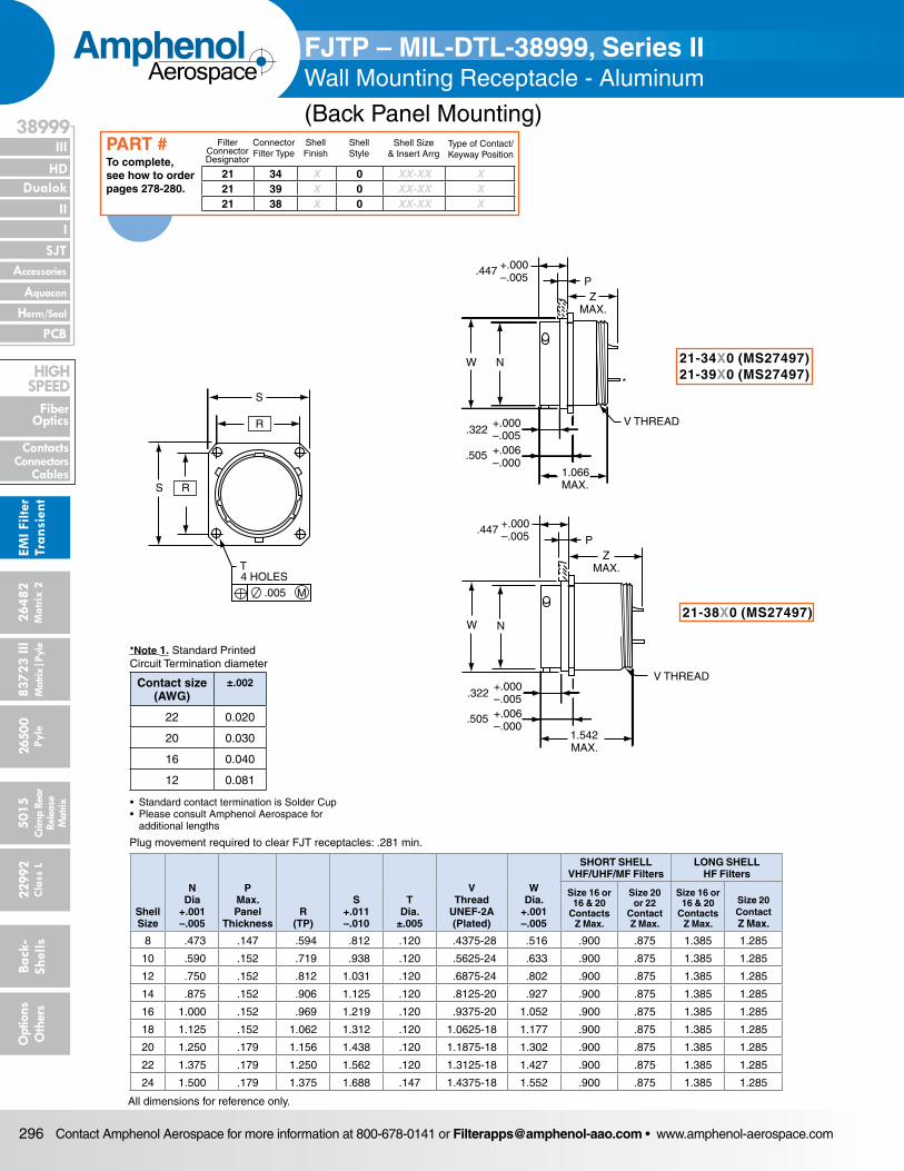
Contact Amphenol Aerospace for more information at 800-678-0141 or [email protected] • www.amphenol-aerospace.com296
AmphenolAerospace
Dualok
III
SJT
38999
PCB
HD
EMI F
ilter
Tran
sien
t
I II
Accessories
Herm/Seal
Aquacon
Fiber Optics
ContactsConnectors
Cables
HIgH SPEED
2648
2M
atrix
2
8372
3 III
5015
2650
0 Py
le
2299
2 C
lass
L
Back
- Sh
ells
Opt
ions
O
ther
sCr
imp
Rear
Rele
ase
Mat
rix
Mat
rix|P
yle
S R
R
S
.005 M
T4 HOLES
PZ
MAX.
.447 +.000–.005
NW
.322+.000–.005
.505 +.006–.000
1.066MAX.
V THREAD
PZ
MAX.
.447 +.000–.005
.322+.000–.005
.505 +.006–.000
1.542MAX.
*
W N
V THREAD
Plug movement required to clear FJT receptacles: .281 min.
Shell Size
N Dia
+.001 –.005
P Max. Panel
ThicknessR
(TP)
S +.011 –.010
T Dia.
±.005
V Thread
UNEF-2A (Plated)
W Dia.
+.001 –.005
SHORT SHELL VHF/UHF/MF Filters
LONG SHELL HF Filters
Size 16 or 16 & 20
Contacts Z Max.
Size 20 or 22
Contact Z Max.
Size 16 or 16 & 20
Contacts Z Max.
Size 20 Contact Z Max.
8 .473 .147 .594 .812 .120 .4375-28 .516 .900 .875 1.385 1.285
10 .590 .152 .719 .938 .120 .5625-24 .633 .900 .875 1.385 1.285
12 .750 .152 .812 1.031 .120 .6875-24 .802 .900 .875 1.385 1.285
14 .875 .152 .906 1.125 .120 .8125-20 .927 .900 .875 1.385 1.285
16 1.000 .152 .969 1.219 .120 .9375-20 1.052 .900 .875 1.385 1.285
18 1.125 .152 1.062 1.312 .120 1.0625-18 1.177 .900 .875 1.385 1.285
20 1.250 .179 1.156 1.438 .120 1.1875-18 1.302 .900 .875 1.385 1.285
22 1.375 .179 1.250 1.562 .120 1.3125-18 1.427 .900 .875 1.385 1.285
24 1.500 .179 1.375 1.688 .147 1.4375-18 1.552 .900 .875 1.385 1.285
All dimensions for reference only.
21-34X0 (MS27497)21-39X0 (MS27497)
21-38X0 (MS27497)
FJTP – MIL-DTL-38999, Series IIWall Mounting Receptacle - Aluminum
(Back Panel Mounting)
21 34 X 0 XX-XX X21 39 X 0 XX-XX X21 38 X 0 XX-XX X
Filter Connector Designator
Connector Filter Type
Shell Finish
Shell Style
Shell Size& Insert Arrg
Type of Contact/Keyway Position
To complete, see how to order pages 278-280.
PART #
*Note 1. Standard Printed Circuit Termination diameter
Contact size (AWG)
±.002
22 0.020
20 0.030
16 0.040
12 0.081
• Standard contact termination is Solder Cup• Please consult Amphenol Aerospace for additional lengths

Contact Amphenol Aerospace for more information at 800-678-0141 or [email protected] • www.amphenol-aerospace.com 297
AmphenolAerospace
II Dualok
III
SJT
38999
I
PCB
Accessories
Aquacon
HD
EMI Filter
Transient
Herm/Seal
Fiber Optics
ContactsConnectorsCables
HIgH SPEED
26482M
atrix 2 83723 IIIM
atrix|Pyle5015
Crimp Rear
Release M
atrix
26500 Pyle
22992 C
lass L Back- Shells
Options
Others
S R
R
S
.005 M
THOLES
N
+.000–.005
.322
.380+.006–.000
1.542MAX.
ZMAX.
ZMAX.
K
+.000–.005
.322
.380+.006–.000
1.066MAX.
*
*
N K
Plug movement required to clear FJT receptacles: .281 min.
Shell Size
K Dia.
+.000 –.007
N Dia
+.001 –.005
R (TP)
S +.011 –.010
T Dia.
±.005
SHORT SHELL VHF/UHF/MF Filters
LONG SHELL HF Filters
Size 20 Contact Z Max.
Size 16 or 16 & 20
Contacts Z Max.
Size 22 Contact Z Max.
Size 20 Contact Z Max.
Size 16 or 16 & 20
Contacts Z Max.
8 .438 .473 .594 .812 .120 .937 .952 .902 1.300 1.496
10 .562 .590 .719 .938 .120 .937 .952 .902 1.300 1.496
12 .688 .750 .812 1.031 .120 .937 .952 .902 1.300 1.496
14 .812 .875 .906 1.125 .120 .937 .952 .902 1.300 1.496
16 .938 1.000 .969 1.219 .120 .937 .952 .902 1.300 1.496
18 1.062 1.125 1.062 1.312 .120 .937 .952 .902 1.300 1.496
20 1.188 1.250 1.156 1.438 .120 .937 .952 .902 1.300 1.496
22 1.312 1.375 1.250 1.562 .120 .937 .952 .902 1.300 1.496
24 1.438 1.500 1.375 1.688 .147 .937 .952 .902 1.300 1.496
All dimensions for reference only.
FJT – MIL-DTL-38999, Series IIBox Mounting Receptacle - Aluminum
21 24 X 2 XX-XX X21 32 X 2 XX-XX X21 37 X 2 XX-XX X
Filter Connector Designator
Connector Filter Type
Shell Finish
Shell Style
Shell Size& Insert Arrg
Type of Contact/Keyway Position
To complete, see how to order pages 278-280.
PART #
21-24X2 (MS27335)21-32X2 (MS27335)
21-37X2 (MS27335)
*Note 1. Standard Printed Circuit Termination diameter
Contact size (AWG)
±.002
22 0.020
20 0.030
16 0.040
12 0.081
• Standard contact termination is Solder Cup• Please consult Amphenol Aerospace for additional lengths
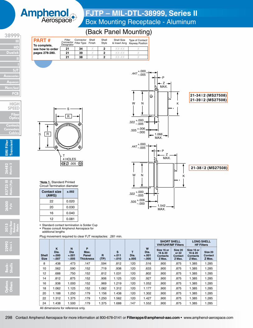
Contact Amphenol Aerospace for more information at 800-678-0141 or [email protected] • www.amphenol-aerospace.com298
AmphenolAerospace
Dualok
III
SJT
38999
PCB
HD
EMI F
ilter
Tran
sien
t
I II
Accessories
Herm/Seal
Aquacon
Fiber Optics
ContactsConnectors
Cables
HIgH SPEED
2648
2M
atrix
2
8372
3 III
5015
2650
0 Py
le
2299
2 C
lass
L
Back
- Sh
ells
Opt
ions
O
ther
sCr
imp
Rear
Rele
ase
Mat
rix
Mat
rix|P
yle
N
1.066MAX.
ZMAX.
KW
.447+.000–.005
+.000–.005.322
+.006–.000
.505
P
ZMAX.
.447+.000–.005
P
1.542MAX.
+.000–.005.322
+.006–.000
.505
*
*
N KW
S R
R
S
.005 M
T4 HOLES
Plug movement required to clear FJT receptacles: .281 min.
Shell Size
K Dia.
+.000 –.007
N Dia
+.001 –.005
P Max. Panel
ThicknessR
(TP)
S +.011 –.010
T Dia.
±.005
W Dia.
+.001 –.005
SHORT SHELL VHF/UHF/MF Filters
LONG SHELL HF Filters
Size 16 or 16 & 20
Contacts Z Max.
Size 20 or 22
Contact Z Max.
Size 16 or 16 & 20
Contacts Z Max.
Size 20 Contact Z Max.
8 .438 .473 .147 .594 .812 .120 .516 .900 .875 1.385 1.285
10 .562 .590 .152 .719 .938 .120 .633 .900 .875 1.385 1.285
12 .688 .750 .152 .812 1.031 .120 .802 .900 .875 1.385 1.285
14 .812 .875 .152 .906 1.125 .120 .927 .900 .875 1.385 1.285
16 .938 1.000 .152 .969 1.219 .120 1.052 .900 .875 1.385 1.285
18 1.062 1.125 .152 1.062 1.312 .120 1.177 .900 .875 1.385 1.285
20 1.188 1.250 .179 1.156 1.438 .120 1.302 .900 .875 1.385 1.285
22 1.312 1.375 .179 1.250 1.562 .120 1.427 .900 .875 1.385 1.285
24 1.438 1.500 .179 1.375 1.688 .147 1.552 .900 .875 1.385 1.285
All dimensions for reference only.
21-34X2 (MS27508)21-39X2 (MS27508)
21-38X2 (MS27508)
FJTP – MIL-DTL-38999, Series II Box Mounting Receptacle - Aluminum
(Back Panel Mounting)
21 34 X 2 XX-XX X21 39 X 2 XX-XX X21 38 X 2 XX-XX X
Filter Connector Designator
Connector Filter Type
Shell Finish
Shell Style
Shell Size& Insert Arrg
Type of Contact/Keyway Position
To complete, see how to order pages 278-280.
PART #
*Note 1. Standard Printed Circuit Termination diameter
Contact size (AWG)
±.002
22 0.020
20 0.030
16 0.040
12 0.081
• Standard contact termination is Solder Cup• Please consult Amphenol Aerospace for additional lengths
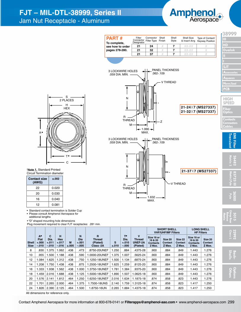
Contact Amphenol Aerospace for more information at 800-678-0141 or [email protected] • www.amphenol-aerospace.com 299
AmphenolAerospace
II Dualok
III
SJT
38999
I
PCB
Accessories
Aquacon
HD
EMI Filter
Transient
Herm/Seal
Fiber Optics
ContactsConnectorsCables
HIgH SPEED
26482M
atrix 2 83723 IIIM
atrix|Pyle5015
Crimp Rear
Release M
atrix
26500 Pyle
22992 C
lass L Back- Shells
Options
Others
S2 PLACES
HHEX
C
A •
•T
3 LOCKWIRE HOLES .059 DIA. MIN.
PANEL THICKNESS.062-.109
V THREAD
3 LOCKWIRE HOLES .059 DIA. MIN.
PANEL THICKNESS.062-.109
N
RTHREAD
MZ
1.066MAX.
RTHREAD
M1.632MAX.
N
V THREAD
*
*
• “D” shaped mounting hole dimensionsPlug movement required to clear FJT receptacles: .281 min.
Shell Size
A• Flat
+.000 –.010
C Dia.
+.011 –.010
HHex
+.017 –.016
M ±.005
N Dia
+.001 –.005
R Thread (Plated)
Class -2AS
±.010
T• Dia.
+.010 –.000
V Thread
UNEF-2A (Plated)
SHORT SHELL VHF/UHF/MF Filters
LONG SHELL HF Filters
Size 16 or 16 & 20
Contacts Z Max.
Size 20 Contact Z Max.
Size 22 Contact Z Max.
Size 16 or 16 & 20
Contacts Z Max.
Size 20 Contact Z Max.
8 .830 1.375 1.062 .438 .473 .8750-20UNEF 1.250 .884 .4375-28 .900 .884 .849 1.443 1.276
10 .955 1.500 1.188 .438 .590 1.0000-20UNEF 1.375 1.007 .5625-24 .900 .884 .849 1.443 1.276
12 1.084 1.625 1.312 .438 .750 1.1250-18UNEF 1.500 1.134 .6875-24 .900 .884 .849 1.443 1.276
14 1.208 1.750 1.438 .438 .875 1.2500-18UNEF 1.625 1.259 .8125-20 .900 .884 .849 1.443 1.276
16 1.333 1.938 1.562 .438 1.000 1.3750-18UNEF 1.781 1.384 .9375-20 .900 .884 .849 1.443 1.276
18 1.459 2.016 1.688 .438 1.125 1.5000-18UNEF 1.890 1.507 1.0625-18 .900 .884 .849 1.443 1.276
20 1.576 2.141 1.812 .464 1.250 1.6250-18UNEF 2.016 1.634 1.1875-18 .874 .858 .823 1.443 1.276
22 1.701 2.265 2.000 .464 1.375 1.7500-18UNS 2.140 1.759 1.3125-18 .874 .858 .823 1.417 1.250
24 1.826 2.390 2.125 .464 1.500 1.8750-16UN 2.265 1.884 1.4375-18 .874 .858 .823 1.417 1.250
All dimensions for reference only.
21-24X7 (MS27337)21-32X7 (MS27337)
21-37X7 (MS27337)
FJT – MIL-DTL-38999, Series II Jam Nut Receptacle - Aluminum
21 24 X 7 XX-XX X21 32 X 7 XX-XX X21 37 X 7 XX-XX X
Filter Connector Designator
Connector Filter Type
Shell Finish
Shell Style
Shell Size& Insert Arrg
Type of Contact/Keyway Position
To complete, see how to order pages 278-280.
PART #
*Note 1. Standard Printed Circuit Termination diameter
Contact size (AWG)
±.002
22 0.020
20 0.030
16 0.040
12 0.081
• Standard contact termination is Solder Cup• Please consult Amphenol Aerospace for additional lengths
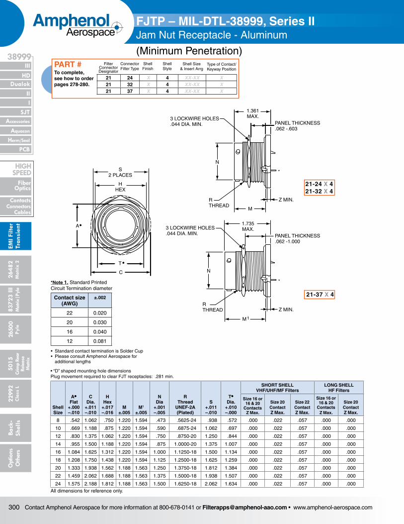
Contact Amphenol Aerospace for more information at 800-678-0141 or [email protected] • www.amphenol-aerospace.com300
AmphenolAerospace
Dualok
III
SJT
38999
PCB
HD
EMI F
ilter
Tran
sien
t
I II
Accessories
Herm/Seal
Aquacon
Fiber Optics
ContactsConnectors
Cables
HIgH SPEED
2648
2M
atrix
2
8372
3 III
5015
2650
0 Py
le
2299
2 C
lass
L
Back
- Sh
ells
Opt
ions
O
ther
sCr
imp
Rear
Rele
ase
Mat
rix
Mat
rix|P
yle
S2 PLACES
HHEX
C
A•
T •
N
3 LOCKWIRE HOLES.044 DIA. MIN.
1.361MAX.
PANEL THICKNESS.062 -.603
RTHREAD
M
Z MIN.
RTHREAD
M1
3 LOCKWIRE HOLES.044 DIA. MIN.
1.735MAX.
PANEL THICKNESS.062 -1.000
N
Z MIN.
*
*
• “D” shaped mounting hole dimensionsPlug movement required to clear FJT receptacles: .281 min.
Shell Size
A• Flat
+.000 –.010
C Dia.
+.011 –.010
HHex
+.017 –.016
M ±.005
M1
±.005
N Dia
+.001 –.005
R Thread
UNEF-2A (Plated)
S +.011 –.010
T• Dia.
+.010 –.000
SHORT SHELL VHF/UHF/MF Filters
LONG SHELL HF Filters
Size 16 or 16 & 20
Contacts Z Max.
Size 20 Contact Z Max.
Size 22 Contact Z Max.
Size 16 or 16 & 20
Contacts Z Max.
Size 20 Contact Z Max.
8 .542 1.062 .750 1.220 1.594 .473 .5625-24 .938 .572 .000 .022 .057 .000 .000
10 .669 1.188 .875 1.220 1.594 .590 .6875-24 1.062 .697 .000 .022 .057 .000 .000
12 .830 1.375 1.062 1.220 1.594 .750 .8750-20 1.250 .844 .000 .022 .057 .000 .000
14 .955 1.500 1.188 1.220 1.594 .875 1.0000-20 1.375 1.007 .000 .022 .057 .000 .000
16 1.084 1.625 1.312 1.220 1.594 1.000 1.1250-18 1.500 1.134 .000 .022 .057 .000 .000
18 1.208 1.750 1.438 1.220 1.594 1.125 1.2500-18 1.625 1.259 .000 .022 .057 .000 .000
20 1.333 1.938 1.562 1.188 1.563 1.250 1.3750-18 1.812 1.384 .000 .022 .057 .000 .000
22 1.459 2.062 1.688 1.188 1.563 1.375 1.5000-18 1.938 1.507 .000 .022 .057 .000 .000
24 1.575 2.188 1.812 1.188 1.563 1.500 1.6250-18 2.062 1.634 .000 .022 .057 .000 .000All dimensions for reference only.
21-24 X 421-32 X 4
21-37 X 4
FJTP – MIL-DTL-38999, Series IIJam Nut Receptacle - Aluminum
(Minimum Penetration)
21 24 X 4 XX-XX X21 32 X 4 XX-XX X21 37 X 4 XX-XX X
Filter Connector Designator
Connector Filter Type
Shell Finish
Shell Style
Shell Size& Insert Arrg
Type of Contact/Keyway Position
To complete, see how to order pages 278-280.
PART #
*Note 1. Standard Printed Circuit Termination diameter
Contact size (AWG)
±.002
22 0.020
20 0.030
16 0.040
12 0.081
• Standard contact termination is Solder Cup• Please consult Amphenol Aerospace for additional lengths
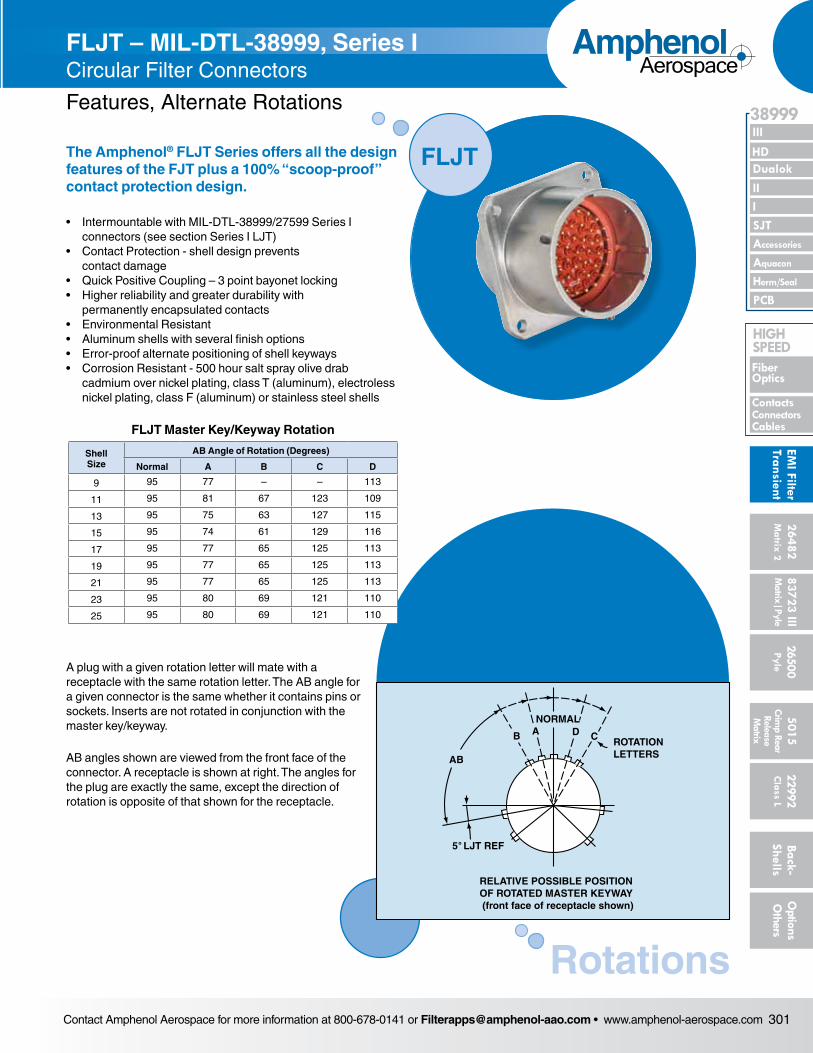
Contact Amphenol Aerospace for more information at 800-678-0141 or [email protected] • www.amphenol-aerospace.com 301
AmphenolAerospace
II Dualok
III
SJT
38999
I
PCB
Accessories
Aquacon
HD
EMI Filter
Transient
Herm/Seal
Fiber Optics
ContactsConnectorsCables
HIgH SPEED
26482M
atrix 2 83723 IIIM
atrix|Pyle5015
Crimp Rear
Release M
atrix
26500 Pyle
22992 C
lass L Back- Shells
Options
Others
FJTP – MIL-DTL-38999, Series IIJam Nut Receptacle - Aluminum
(Minimum Penetration)
The Amphenol® FLJT Series offers all the design features of the FJT plus a 100% “scoop-proof” contact protection design.
• Intermountable with MIL-DTL-38999/27599 Series I connec tors (see section Series I LJT)
• Contact Protection - shell design prevents contact damage
• Quick Positive Coupling – 3 point bayonet locking• Higher reliability and greater durability with
permanently encapsulated contacts• Environmental Resistant• Aluminum shells with several finish options• Error-proof alternate positioning of shell keyways• Corrosion Resistant - 500 hour salt spray olive drab
cad mium over nickel plating, class T (aluminum), electroless nickel plating, class F (aluminum) or stainless steel shells
FLJT – MIL-DTL-38999, Series I Circular Filter Connectors
Features, Alternate Rotations
A plug with a given rotation letter will mate with a receptacle with the same rotation letter. The AB angle for a given connec tor is the same whether it contains pins or sockets. Inserts are not rotated in conjunction with the master key/keyway.
AB angles shown are viewed from the front face of the connec tor. A receptacle is shown at right. The angles for the plug are exactly the same, except the direction of rotation is opposite of that shown for the receptacle.
FLJT
Rotations
RELATIVE POSSIBLE POSITIONOF ROTATED MASTER KEYWAY (front face of receptacle shown)
ROTATIONLETTERS
NORMAL
B A D C
AB
5 LJT REF˚
FLJT Master Key/Keyway Rotation
Shell Size
AB Angle of Rotation (Degrees)
Normal A B C D
9 95 77 – – 113
11 95 81 67 123 109
13 95 75 63 127 115
15 95 74 61 129 116
17 95 77 65 125 113
19 95 77 65 125 113
21 95 77 65 125 113
23 95 80 69 121 110
25 95 80 69 121 110
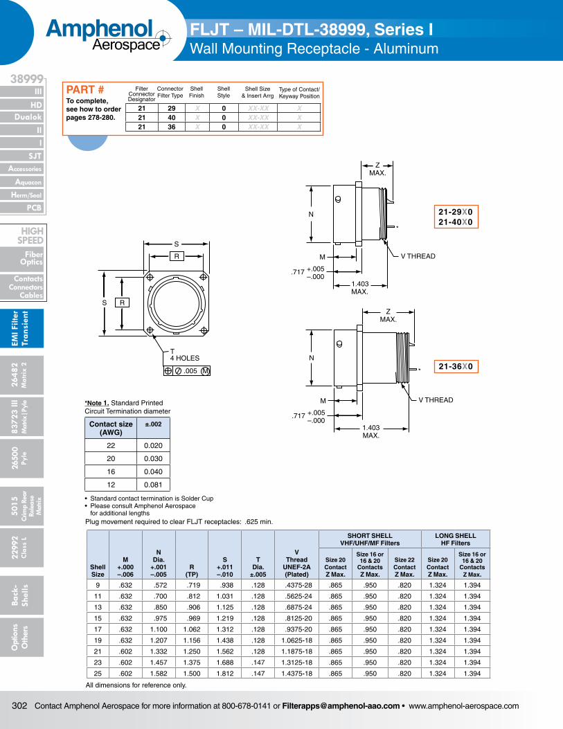
Contact Amphenol Aerospace for more information at 800-678-0141 or [email protected] • www.amphenol-aerospace.com302
AmphenolAerospace
Dualok
III
SJT
38999
PCB
HD
EMI F
ilter
Tran
sien
t
I II
Accessories
Herm/Seal
Aquacon
Fiber Optics
ContactsConnectors
Cables
HIgH SPEED
2648
2M
atrix
2
8372
3 III
5015
2650
0 Py
le
2299
2 C
lass
L
Back
- Sh
ells
Opt
ions
O
ther
sCr
imp
Rear
Rele
ase
Mat
rix
Mat
rix|P
yle
S
R
S R
T4 HOLES
.005 M
N
ZMAX.
V THREADM
1.403MAX.
+.005–.000
.717
ZMAX.
N
V THREADM
1.403MAX.
+.005–.000
.717
*
*
Plug movement required to clear FLJT receptacles: .625 min.
Shell Size
M +.000 –.006
N Dia.
+.001 –.005
R (TP)
S +.011 –.010
T Dia.
±.005
V Thread
UNEF-2A (Plated)
SHORT SHELL VHF/UHF/MF Filters
LONG SHELL HF Filters
Size 20 Contact Z Max.
Size 16 or 16 & 20
Contacts Z Max.
Size 22 Contact Z Max.
Size 20 Contact Z Max.
Size 16 or 16 & 20
Contacts Z Max.
9 .632 .572 .719 .938 .128 .4375-28 .865 .950 .820 1.324 1.394
11 .632 .700 .812 1.031 .128 .5625-24 .865 .950 .820 1.324 1.394
13 .632 .850 .906 1.125 .128 .6875-24 .865 .950 .820 1.324 1.394
15 .632 .975 .969 1.219 .128 .8125-20 .865 .950 .820 1.324 1.394
17 .632 1.100 1.062 1.312 .128 .9375-20 .865 .950 .820 1.324 1.394
19 .632 1.207 1.156 1.438 .128 1.0625-18 .865 .950 .820 1.324 1.394
21 .602 1.332 1.250 1.562 .128 1.1875-18 .865 .950 .820 1.324 1.394
23 .602 1.457 1.375 1.688 .147 1.3125-18 .865 .950 .820 1.324 1.394
25 .602 1.582 1.500 1.812 .147 1.4375-18 .865 .950 .820 1.324 1.394
All dimensions for reference only.
21-29X021-40X0
21-36X0
FLJT – MIL-DTL-38999, Series I Wall Mounting Receptacle - Aluminum
21 29 X 0 XX-XX X21 40 X 0 XX-XX X21 36 X 0 XX-XX X
Filter Connector Designator
Connector Filter Type
Shell Finish
Shell Style
Shell Size& Insert Arrg
Type of Contact/Keyway Position
To complete, see how to order pages 278-280.
PART #
*Note 1. Standard Printed Circuit Termination diameter
Contact size (AWG)
±.002
22 0.020
20 0.030
16 0.040
12 0.081
• Standard contact termination is Solder Cup• Please consult Amphenol Aerospace for additional lengths
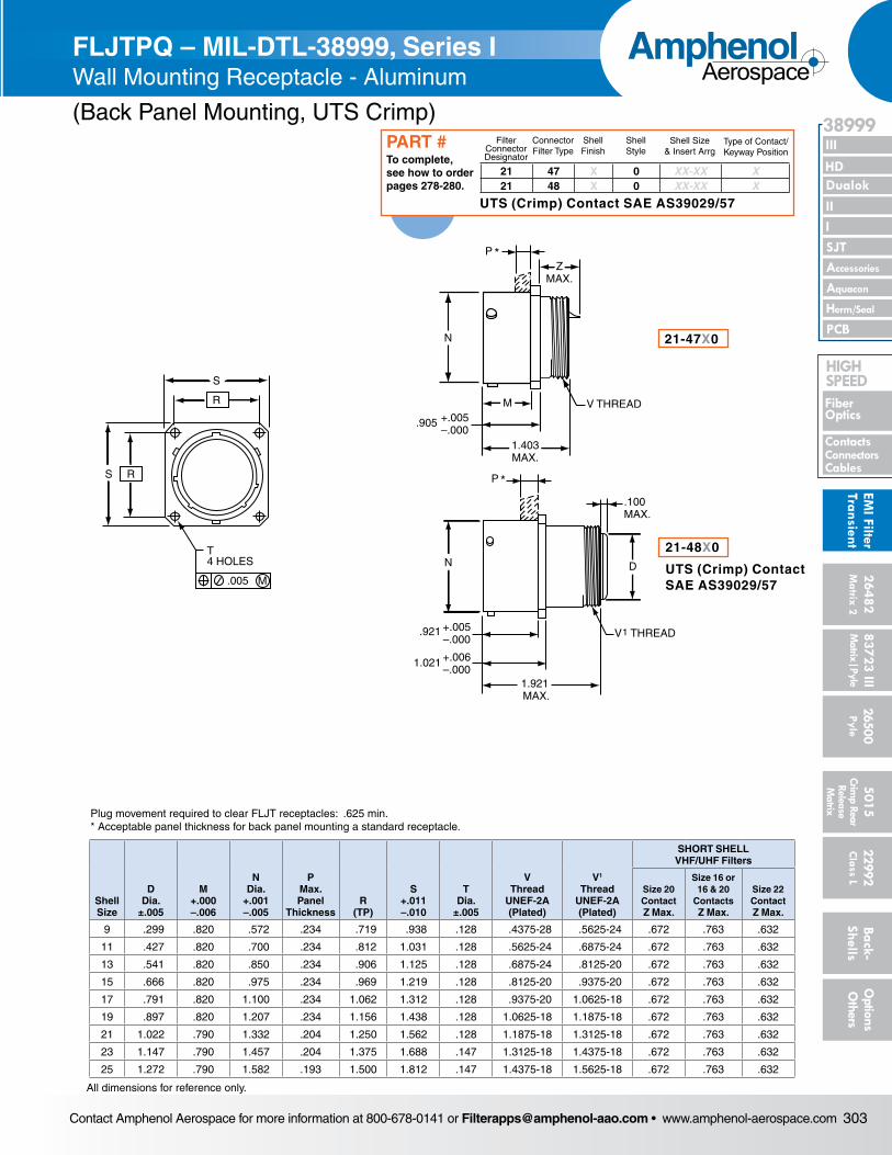
Contact Amphenol Aerospace for more information at 800-678-0141 or [email protected] • www.amphenol-aerospace.com 303
AmphenolAerospace
II Dualok
III
SJT
38999
I
PCB
Accessories
Aquacon
HD
EMI Filter
Transient
Herm/Seal
Fiber Optics
ContactsConnectorsCables
HIgH SPEED
26482M
atrix 2 83723 IIIM
atrix|Pyle5015
Crimp Rear
Release M
atrix
26500 Pyle
22992 C
lass L Back- Shells
Options
Others
FLJT – MIL-DTL-38999, Series I Wall Mounting Receptacle - Aluminum
S
R
S R
T4 HOLES
.005 M
ZMAX.
V THREADM
1.403MAX.
+.005–.000
.905
N
P *
P *
D
V THREAD1+.005–.000
.921
+.006–.000
1.021
1.921 MAX.
N
.100MAX.
Plug movement required to clear FLJT receptacles: .625 min. * Acceptable panel thickness for back panel mounting a standard receptacle.
Shell Size
D Dia.
±.005
M +.000 –.006
N Dia.
+.001 –.005
P Max. Panel
ThicknessR
(TP)
S +.011 –.010
T Dia.
±.005
V Thread
UNEF-2A (Plated)
V1
Thread UNEF-2A (Plated)
SHORT SHELL VHF/UHF Filters
Size 20 Contact Z Max.
Size 16 or 16 & 20
Contacts Z Max.
Size 22 Contact Z Max.
9 .299 .820 .572 .234 .719 .938 .128 .4375-28 .5625-24 .672 .763 .632
11 .427 .820 .700 .234 .812 1.031 .128 .5625-24 .6875-24 .672 .763 .632
13 .541 .820 .850 .234 .906 1.125 .128 .6875-24 .8125-20 .672 .763 .632
15 .666 .820 .975 .234 .969 1.219 .128 .8125-20 .9375-20 .672 .763 .632
17 .791 .820 1.100 .234 1.062 1.312 .128 .9375-20 1.0625-18 .672 .763 .632
19 .897 .820 1.207 .234 1.156 1.438 .128 1.0625-18 1.1875-18 .672 .763 .632
21 1.022 .790 1.332 .204 1.250 1.562 .128 1.1875-18 1.3125-18 .672 .763 .632
23 1.147 .790 1.457 .204 1.375 1.688 .147 1.3125-18 1.4375-18 .672 .763 .632
25 1.272 .790 1.582 .193 1.500 1.812 .147 1.4375-18 1.5625-18 .672 .763 .632
All dimensions for reference only.
21-47X0
21-48X0
UTS (Crimp) ContactSAE AS39029/57
FLJTPQ – MIL-DTL-38999, Series I Wall Mounting Receptacle - Aluminum
(Back Panel Mounting, UTS Crimp)
21 47 X 0 XX-XX X21 48 X 0 XX-XX X
Filter Connector Designator
Connector Filter Type
Shell Finish
Shell Style
Shell Size& Insert Arrg
Type of Contact/Keyway Position
To complete, see how to order pages 278-280.
PART #
UTS (Crimp) Contact SAE AS39029/57
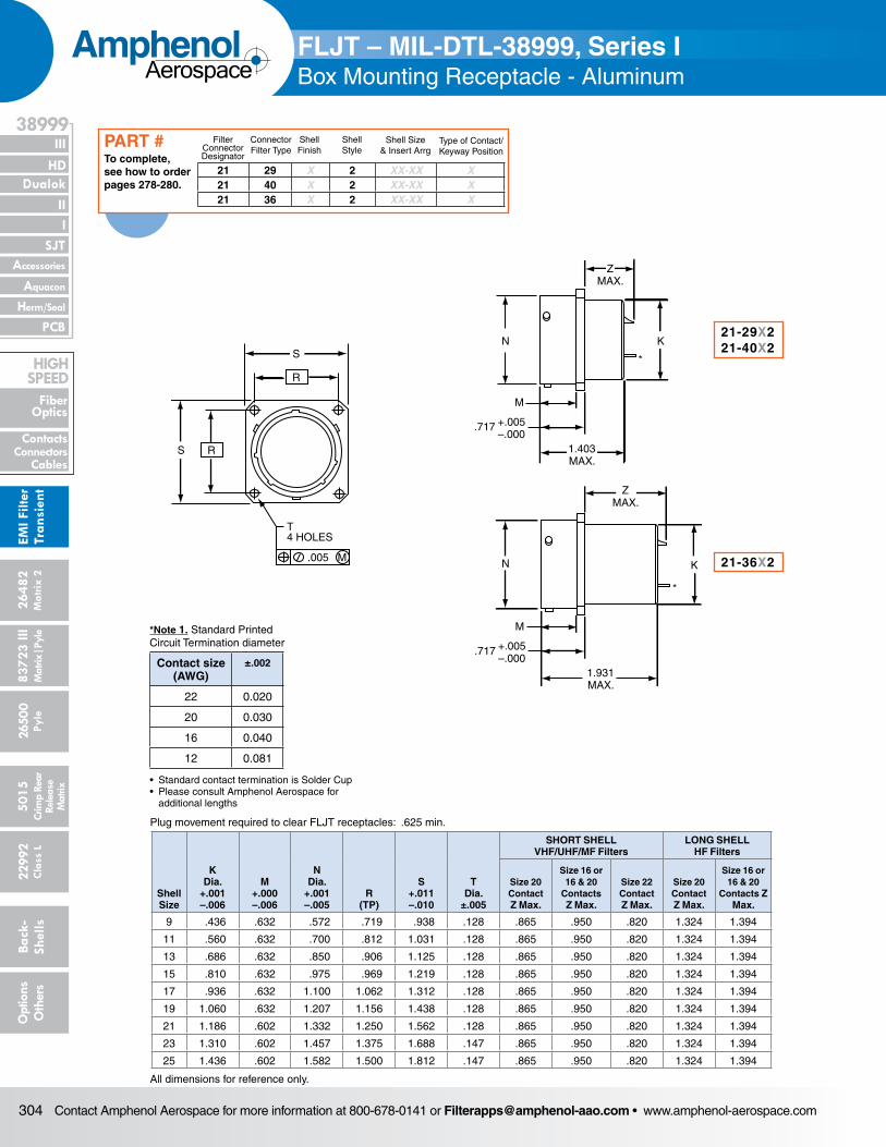
Contact Amphenol Aerospace for more information at 800-678-0141 or [email protected] • www.amphenol-aerospace.com304
AmphenolAerospace
Dualok
III
SJT
38999
PCB
HD
EMI F
ilter
Tran
sien
t
I II
Accessories
Herm/Seal
Aquacon
Fiber Optics
ContactsConnectors
Cables
HIgH SPEED
2648
2M
atrix
2
8372
3 III
5015
2650
0 Py
le
2299
2 C
lass
L
Back
- Sh
ells
Opt
ions
O
ther
sCr
imp
Rear
Rele
ase
Mat
rix
Mat
rix|P
yle
S
R
S R
T4 HOLES
.005 M
N
ZMAX.
K
1.403MAX.
+.005–.000
.717
M
N
ZMAX.
K
1.931MAX.
+.005–.000
.717
M
*
*
Plug movement required to clear FLJT receptacles: .625 min.
Shell Size
K Dia.
+.001 –.006
M +.000 –.006
N Dia.
+.001 –.005
R (TP)
S +.011 –.010
T Dia.
±.005
SHORT SHELL VHF/UHF/MF Filters
LONG SHELL HF Filters
Size 20 Contact Z Max.
Size 16 or 16 & 20
Contacts Z Max.
Size 22 Contact Z Max.
Size 20 Contact Z Max.
Size 16 or 16 & 20
Contacts Z Max.
9 .436 .632 .572 .719 .938 .128 .865 .950 .820 1.324 1.394
11 .560 .632 .700 .812 1.031 .128 .865 .950 .820 1.324 1.394
13 .686 .632 .850 .906 1.125 .128 .865 .950 .820 1.324 1.394
15 .810 .632 .975 .969 1.219 .128 .865 .950 .820 1.324 1.394
17 .936 .632 1.100 1.062 1.312 .128 .865 .950 .820 1.324 1.394
19 1.060 .632 1.207 1.156 1.438 .128 .865 .950 .820 1.324 1.394
21 1.186 .602 1.332 1.250 1.562 .128 .865 .950 .820 1.324 1.394
23 1.310 .602 1.457 1.375 1.688 .147 .865 .950 .820 1.324 1.394
25 1.436 .602 1.582 1.500 1.812 .147 .865 .950 .820 1.324 1.394
All dimensions for reference only.
21-29X221-40X2
21-36X2
FLJT – MIL-DTL-38999, Series IBox Mounting Receptacle - Aluminum
21 29 X 2 XX-XX X21 40 X 2 XX-XX X21 36 X 2 XX-XX X
Filter Connector Designator
Connector Filter Type
Shell Finish
Shell Style
Shell Size& Insert Arrg
Type of Contact/Keyway Position
To complete, see how to order pages 278-280.
PART #
*Note 1. Standard Printed Circuit Termination diameter
Contact size (AWG)
±.002
22 0.020
20 0.030
16 0.040
12 0.081
• Standard contact termination is Solder Cup• Please consult Amphenol Aerospace for additional lengths
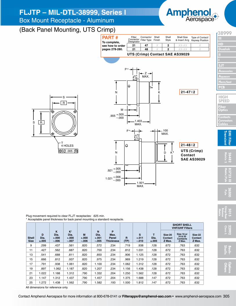
Contact Amphenol Aerospace for more information at 800-678-0141 or [email protected] • www.amphenol-aerospace.com 305
AmphenolAerospace
II Dualok
III
SJT
38999
I
PCB
Accessories
Aquacon
HD
EMI Filter
Transient
Herm/Seal
Fiber Optics
ContactsConnectorsCables
HIgH SPEED
26482M
atrix 2 83723 IIIM
atrix|Pyle5015
Crimp Rear
Release M
atrix
26500 Pyle
22992 C
lass L Back- Shells
Options
Others
S
R
S R
T4 HOLES
.005 M
N K
ZMAX.
P *
P *
M
1.403MAX.
+.005–.000
.905
N
.921+.005–.000
1.021 +.006–.000
1.921MAX.
D K1
.100MAX.
FLJT – MIL-DTL-38999, Series IBox Mounting Receptacle - Aluminum
Plug movement required to clear FLJT receptacles: .625 min.* Acceptable panel thickness for back panel mounting a standard receptacle.
Shell Size
D Dia.
±.005
K Dia.
+.000 –.006
K1
Dia. +.000 –.007
M +.000 –.006
N Dia.
+.001 –.005
P Max. Panel
ThicknessR
(TP)
S +.011 –.010
T Dia.
±.005
SHORT SHELL VHF/UHF Filters
Size 20 Contact Z Max.
Size 16 or 16 & 20
Contacts Z Max.
Size 22 Contact Z Max.
9 .299 .437 .561 .820 .572 .234 .719 .938 .128 .672 .763 .632
11 .427 .562 .687 .820 .700 .234 .812 1.031 .128 .672 .763 .632
13 .541 .688 .811 .820 .850 .234 .906 1.125 .128 .672 .763 .632
15 .666 .812 .937 .820 .975 .234 .969 1.219 .128 .672 .763 .632
17 .791 .938 1.061 .820 1.100 .234 1.062 1.312 .128 .672 .763 .632
19 .897 1.062 1.187 .820 1.207 .234 1.156 1.438 .128 .672 .763 .632
21 1.022 1.188 1.312 .790 1.332 .204 1.250 1.562 .128 .672 .763 .632
23 1.147 1.312 1.437 .790 1.457 .204 1.375 1.688 .147 .672 .763 .632
25 1.272 1.438 1.562 .790 1.582 .193 1.500 1.812 .147 .672 .763 .632
All dimensions for reference only.
21-47X2
21-48X2
UTS (Crimp) ContactSAE AS39029
FLJTP – MIL-DTL-38999, Series IBox Mount Receptacle - Aluminum
(Back Panel Mounting, UTS Crimp)
21 47 X 2 XX-XX X21 48 X 2 XX-XX X
Filter Connector Designator
Connector Filter Type
Shell Finish
Shell Style
Shell Size& Insert Arrg
Type of Contact/Keyway Position
To complete, see how to order pages 278-280.
PART #
UTS (Crimp) Contact SAE AS39029
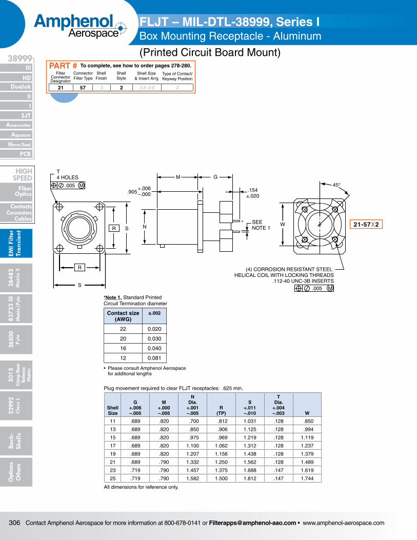
Contact Amphenol Aerospace for more information at 800-678-0141 or [email protected] • www.amphenol-aerospace.com306
AmphenolAerospace
Dualok
III
SJT
38999
PCB
HD
EMI F
ilter
Tran
sien
t
I II
Accessories
Herm/Seal
Aquacon
Fiber Optics
ContactsConnectors
Cables
HIgH SPEED
2648
2M
atrix
2
8372
3 III
5015
2650
0 Py
le
2299
2 C
lass
L
Back
- Sh
ells
Opt
ions
O
ther
sCr
imp
Rear
Rele
ase
Mat
rix
Mat
rix|P
yle
45°
W
(4) CORROSION RESISTANT STEEL HELICAL COIL WITH LOCKING THREADS
.112-40 UNC-3B INSERTS.005 M
GM
.154±.020
.905+.006–.000
NSEENOTE 1
*R S
R
S
T4 HOLES
.005 M
Shell Size
G +.006 –.005
M +.000 –.005
N Dia.
+.001 –.005
R (TP)
S +.011 –.010
T Dia.
+.004 –.003 W
11 .689 .820 .700 .812 1.031 .128 .850
13 .689 .820 .850 .906 1.125 .128 .994
15 .689 .820 .975 .969 1.219 .128 1.119
17 .689 .820 1.100 1.062 1.312 .128 1.237
19 .689 .820 1.207 1.156 1.438 .128 1.379
21 .689 .790 1.332 1.250 1.562 .128 1.489
23 .719 .790 1.457 1.375 1.688 .147 1.619
25 .719 .790 1.582 1.500 1.812 .147 1.744
All dimensions for reference only.
FLJT – MIL-DTL-38999, Series IBox Mounting Receptacle - Aluminum
(Printed Circuit Board Mount)
21-57X2
Plug movement required to clear FLJT receptacles: .625 min.
21 57 X 2 XX-XX X
Filter Connector Designator
Connector Filter Type
Shell Finish
Shell Style
Shell Size& Insert Arrg
Type of Contact/Keyway Position
To complete, see how to order pages 278-280.PART #
*Note 1. Standard Printed Circuit Termination diameter
Contact size (AWG)
±.002
22 0.020
20 0.030
16 0.040
12 0.081
• Please consult Amphenol Aerospace for additional lengths
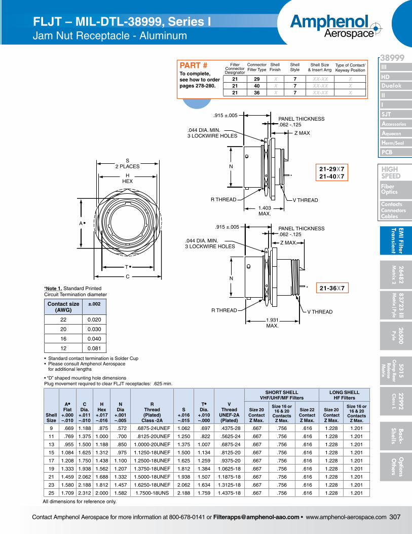
Contact Amphenol Aerospace for more information at 800-678-0141 or [email protected] • www.amphenol-aerospace.com 307
AmphenolAerospace
II Dualok
III
SJT
38999
I
PCB
Accessories
Aquacon
HD
EMI Filter
Transient
Herm/Seal
Fiber Optics
ContactsConnectorsCables
HIgH SPEED
26482M
atrix 2 83723 IIIM
atrix|Pyle5015
Crimp Rear
Release M
atrix
26500 Pyle
22992 C
lass L Back- Shells
Options
Others
S2 PLACES
HHEX
C
A •
T •
V THREADR THREAD
1.403MAX.
.044 DIA. MIN.3 LOCKWIRE HOLES
.915 ±.005
N
PANEL THICKNESS.062 -.125
Z MAX
.044 DIA. MIN.3 LOCKWIRE HOLES
.915 ±.005 PANEL THICKNESS.062 -.125
Z MAX.
R THREAD
N
V THREAD
1.931MAX.
*
*
FLJT – MIL-DTL-38999, Series IBox Mounting Receptacle - Aluminum
(Printed Circuit Board Mount)
• “D” shaped mounting hole dimensionsPlug movement required to clear FLJT receptacles: .625 min.
Shell Size
A• Flat
+.000 –.010
C Dia.
+.011 –.010
HHex
+.017 –.016
N Dia
+.001 –.005
R Thread (Plated)
Class -2A
S +.016 –.015
T• Dia.
+.010 –.000
V Thread
UNEF-2A (Plated)
SHORT SHELL VHF/UHF/MF Filters
LONG SHELL HF Filters
Size 20 Contact Z Max.
Size 16 or 16 & 20
Contacts Z Max.
Size 22 Contact Z Max.
Size 20 Contact Z Max.
Size 16 or 16 & 20
Contacts Z Max.
9 .669 1.188 .875 .572 .6875-24UNEF 1.062 .697 .4375-28 .667 .756 .616 1.228 1.201
11 .769 1.375 1.000 .700 .8125-20UNEF 1.250 .822 .5625-24 .667 .756 .616 1.228 1.201
13 .955 1.500 1.188 .850 1.0000-20UNEF 1.375 1.007 .6875-24 .667 .756 .616 1.228 1.201
15 1.084 1.625 1.312 .975 1.1250-18UNEF 1.500 1.134 .8125-20 .667 .756 .616 1.228 1.201
17 1.208 1.750 1.438 1.100 1.2500-18UNEF 1.625 1.259 .9375-20 .667 .756 .616 1.228 1.201
19 1.333 1.938 1.562 1.207 1.3750-18UNEF 1.812 1.384 1.0625-18 .667 .756 .616 1.228 1.201
21 1.459 2.062 1.688 1.332 1.5000-18UNEF 1.938 1.507 1.1875-18 .667 .756 .616 1.228 1.201
23 1.580 2.188 1.812 1.457 1.6250-18UNEF 2.062 1.634 1.3125-18 .667 .756 .616 1.228 1.201
25 1.709 2.312 2.000 1.582 1.7500-18UNS 2.188 1.759 1.4375-18 .667 .756 .616 1.228 1.201
All dimensions for reference only.
21-29X721-40X7
21-36X7
FLJT – MIL-DTL-38999, Series IJam Nut Receptacle - Aluminum
21 29 X 7 XX-XX X21 40 X 7 XX-XX X21 36 X 7 XX-XX X
Filter Connector Designator
Connector Filter Type
Shell Finish
Shell Style
Shell Size& Insert Arrg
Type of Contact/Keyway Position
To complete, see how to order pages 278-280.
PART #
*Note 1. Standard Printed Circuit Termination diameter
Contact size (AWG)
±.002
22 0.020
20 0.030
16 0.040
12 0.081
• Standard contact termination is Solder Cup• Please consult Amphenol Aerospace for additional lengths
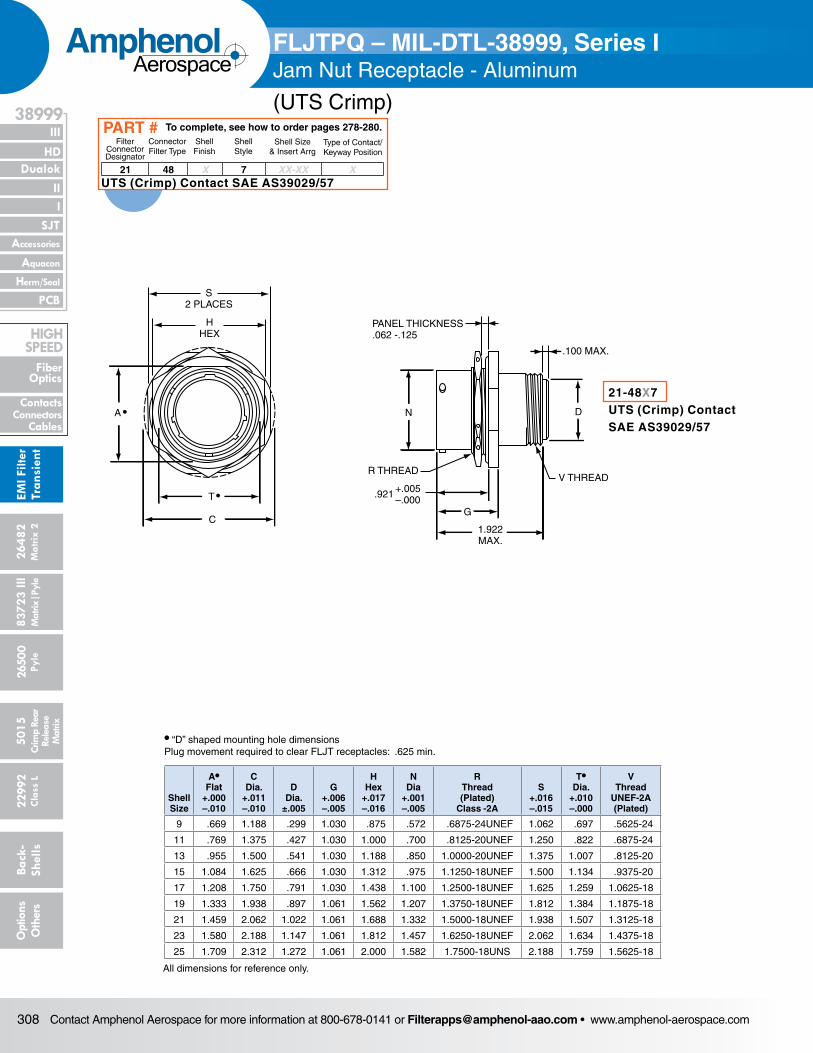
Contact Amphenol Aerospace for more information at 800-678-0141 or [email protected] • www.amphenol-aerospace.com308
AmphenolAerospace
Dualok
III
SJT
38999
PCB
HD
EMI F
ilter
Tran
sien
t
I II
Accessories
Herm/Seal
Aquacon
Fiber Optics
ContactsConnectors
Cables
HIgH SPEED
2648
2M
atrix
2
8372
3 III
5015
2650
0 Py
le
2299
2 C
lass
L
Back
- Sh
ells
Opt
ions
O
ther
sCr
imp
Rear
Rele
ase
Mat
rix
Mat
rix|P
yle
S2 PLACES
HHEX
C
A
•
•
T
PANEL THICKNESS.062 -.125
N
1.922MAX.
G
R THREADV THREAD
D
.100 MAX.
+.005–.000
.921
• “D” shaped mounting hole dimensionsPlug movement required to clear FLJT receptacles: .625 min.
Shell Size
A• Flat
+.000 –.010
C Dia.
+.011 –.010
D Dia.
±.005
G +.006 –.005
HHex
+.017 –.016
N Dia
+.001 –.005
R Thread (Plated)
Class -2A
S +.016 –.015
T• Dia.
+.010 –.000
V Thread
UNEF-2A (Plated)
9 .669 1.188 .299 1.030 .875 .572 .6875-24UNEF 1.062 .697 .5625-24
11 .769 1.375 .427 1.030 1.000 .700 .8125-20UNEF 1.250 .822 .6875-24
13 .955 1.500 .541 1.030 1.188 .850 1.0000-20UNEF 1.375 1.007 .8125-20
15 1.084 1.625 .666 1.030 1.312 .975 1.1250-18UNEF 1.500 1.134 .9375-20
17 1.208 1.750 .791 1.030 1.438 1.100 1.2500-18UNEF 1.625 1.259 1.0625-18
19 1.333 1.938 .897 1.061 1.562 1.207 1.3750-18UNEF 1.812 1.384 1.1875-18
21 1.459 2.062 1.022 1.061 1.688 1.332 1.5000-18UNEF 1.938 1.507 1.3125-18
23 1.580 2.188 1.147 1.061 1.812 1.457 1.6250-18UNEF 2.062 1.634 1.4375-18
25 1.709 2.312 1.272 1.061 2.000 1.582 1.7500-18UNS 2.188 1.759 1.5625-18
All dimensions for reference only.
21-48X7UTS (Crimp) ContactSAE AS39029/57
FLJTPQ – MIL-DTL-38999, Series IJam Nut Receptacle - Aluminum
(UTS Crimp)
21 48 X 7 XX-XX X
Filter Connector Designator
Connector Filter Type
Shell Finish
Shell Style
Shell Size& Insert Arrg
Type of Contact/Keyway Position
To complete, see how to order pages 278-280.PART #
UTS (Crimp) Contact SAE AS39029/57
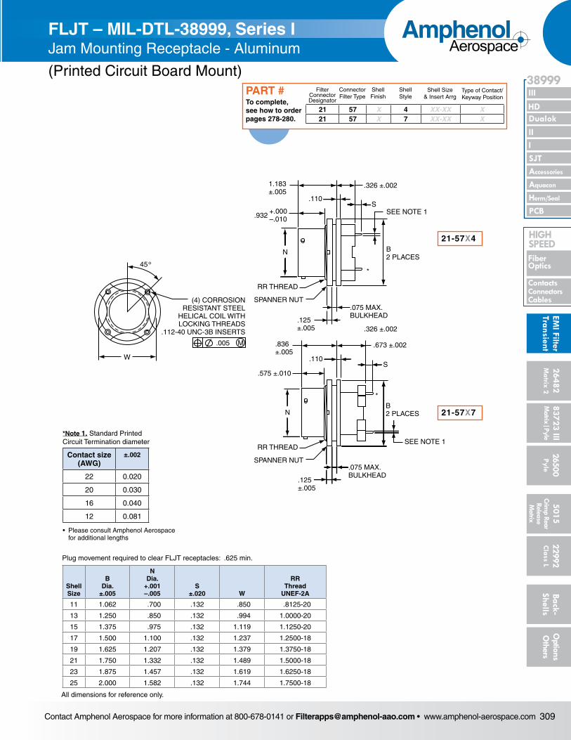
Contact Amphenol Aerospace for more information at 800-678-0141 or [email protected] • www.amphenol-aerospace.com 309
AmphenolAerospace
II Dualok
III
SJT
38999
I
PCB
Accessories
Aquacon
HD
EMI Filter
Transient
Herm/Seal
Fiber Optics
ContactsConnectorsCables
HIgH SPEED
26482M
atrix 2 83723 IIIM
atrix|Pyle5015
Crimp Rear
Release M
atrix
26500 Pyle
22992 C
lass L Back- Shells
Options
Others
W
45°
SEE NOTE 1
1.183±.005
.110
.326 ±.002
S
RR THREAD
SPANNER NUT
RR THREAD
SPANNER NUT
.075 MAX.BULKHEAD
.125±.005
B2 PLACES
+.000–.010.932
SEE NOTE 1
.836±.005
.110
.326 ±.002
S.575 ±.010
.673 ±.002
*
*
.075 MAX.BULKHEAD
.125±.005
B2 PLACESN
N
(4) CORROSIONRESISTANT STEEL
HELICAL COIL WITHLOCKING THREADS
.112-40 UNC-3B INSERTS
.005 M
Shell Size
B Dia.
±.005
N Dia.
+.001 –.005
S ±.020 W
RR Thread
UNEF-2A
11 1.062 .700 .132 .850 .8125-20
13 1.250 .850 .132 .994 1.0000-20
15 1.375 .975 .132 1.119 1.1250-20
17 1.500 1.100 .132 1.237 1.2500-18
19 1.625 1.207 .132 1.379 1.3750-18
21 1.750 1.332 .132 1.489 1.5000-18
23 1.875 1.457 .132 1.619 1.6250-18
25 2.000 1.582 .132 1.744 1.7500-18
All dimensions for reference only.
21-57X7
21-57X4
FLJT – MIL-DTL-38999, Series I Jam Mounting Receptacle - Aluminum
(Printed Circuit Board Mount)
21 57 X 4 XX-XX X21 57 X 7 XX-XX X
Filter Connector Designator
Connector Filter Type
Shell Finish
Shell Style
Shell Size& Insert Arrg
Type of Contact/Keyway Position
To complete, see how to order pages 278-280.
PART #
Plug movement required to clear FLJT receptacles: .625 min.
*Note 1. Standard Printed Circuit Termination diameter
Contact size (AWG)
±.002
22 0.020
20 0.030
16 0.040
12 0.081
• Please consult Amphenol Aerospace for additional lengths
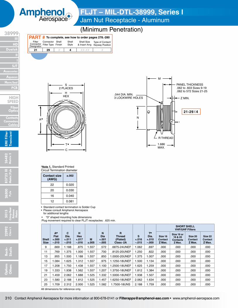
Contact Amphenol Aerospace for more information at 800-678-0141 or [email protected] • www.amphenol-aerospace.com310
AmphenolAerospace
Dualok
III
SJT
38999
PCB
HD
EMI F
ilter
Tran
sien
t
I II
Accessories
Herm/Seal
Aquacon
Fiber Optics
ContactsConnectors
Cables
HIgH SPEED
2648
2M
atrix
2
8372
3 III
5015
2650
0 Py
le
2299
2 C
lass
L
Back
- Sh
ells
Opt
ions
O
ther
sCr
imp
Rear
Rele
ase
Mat
rix
Mat
rix|P
yle
S2 PLACES
HHEX
C
A•
T •
M
Z MIN.
N
.044 DIA. MIN.3 LOCKWIRE HOLES
PANEL THICKNESS.062 to .603 Sizes 9-19.062 to 572 Sizes 21-25
R THREAD
1.686MAX.
*
• “D” shaped mounting hole dimensionsPlug movement required to clear FLJT receptacles: .625 min.
Shell Size
A• Flat
+.000 –.010
C Dia.
+.011 –.010
HHex
+.017 –.016
M ±.005
N Dia
+.001 –.005
R Thread (Plated)
Class -2A
S +.016 –.015
T• Dia.
+.010 –.000
SHORT SHELL VHF/UHF Filters
Size 16 Contact Z Max.
Size 16 or 16 & 20
Contacts Z Max.
Size 20 Contact Z Max.
Size 22 Contact Z Max.
9 .669 1.188 .875 1.557 .572 .6875-24UNEF 1.062 .697 .000 .000 .000 .000
11 .769 1.375 1.000 1.557 .700 .8125-20UNEF 1.250 .822 .000 .000 .000 .000
13 .955 1.500 1.188 1.557 .850 1.0000-20UNEF 1.375 1.007 .000 .000 .000 .000
15 1.084 1.625 1.312 1.557 .975 1.1250-18UNEF 1.500 1.134 .000 .000 .000 .000
17 1.208 1.750 1.438 1.557 1.100 1.2500-18UNEF 1.625 1.259 .000 .000 .000 .000
19 1.333 1.938 1.562 1.557 1.207 1.3750-18UNEF 1.812 1.384 .000 .000 .000 .000
21 1.459 2.062 1.688 1.525 1.332 1.5000-18UNEF 1.938 1.507 .000 .000 .000 .000
23 1.580 2.188 1.812 1.525 1.457 1.6250-18UNEF 2.062 1.634 .000 .000 .000 .000
25 1.709 2.312 2.000 1.525 1.582 1.7500-18UNS 2.188 1.759 .000 .000 .000 .000
All dimensions for reference only.
FLJT – MIL-DTL-38999, Series IJam Nut Receptacle - Aluminum
(Minimum Penetration)
21 29 X 4 XX-XX X
Filter Connector Designator
Connector Filter Type
Shell Finish
Shell Style
Shell Size& Insert Arrg
Type of Contact/Keyway Position
To complete, see how to order pages 278.-280PART #
21-29X4
*Note 1. Standard Printed Circuit Termination diameter
Contact size (AWG)
±.002
22 0.020
20 0.030
16 0.040
12 0.081
• Standard contact termination is Solder Cup• Please consult Amphenol Aerospace for additional lengths
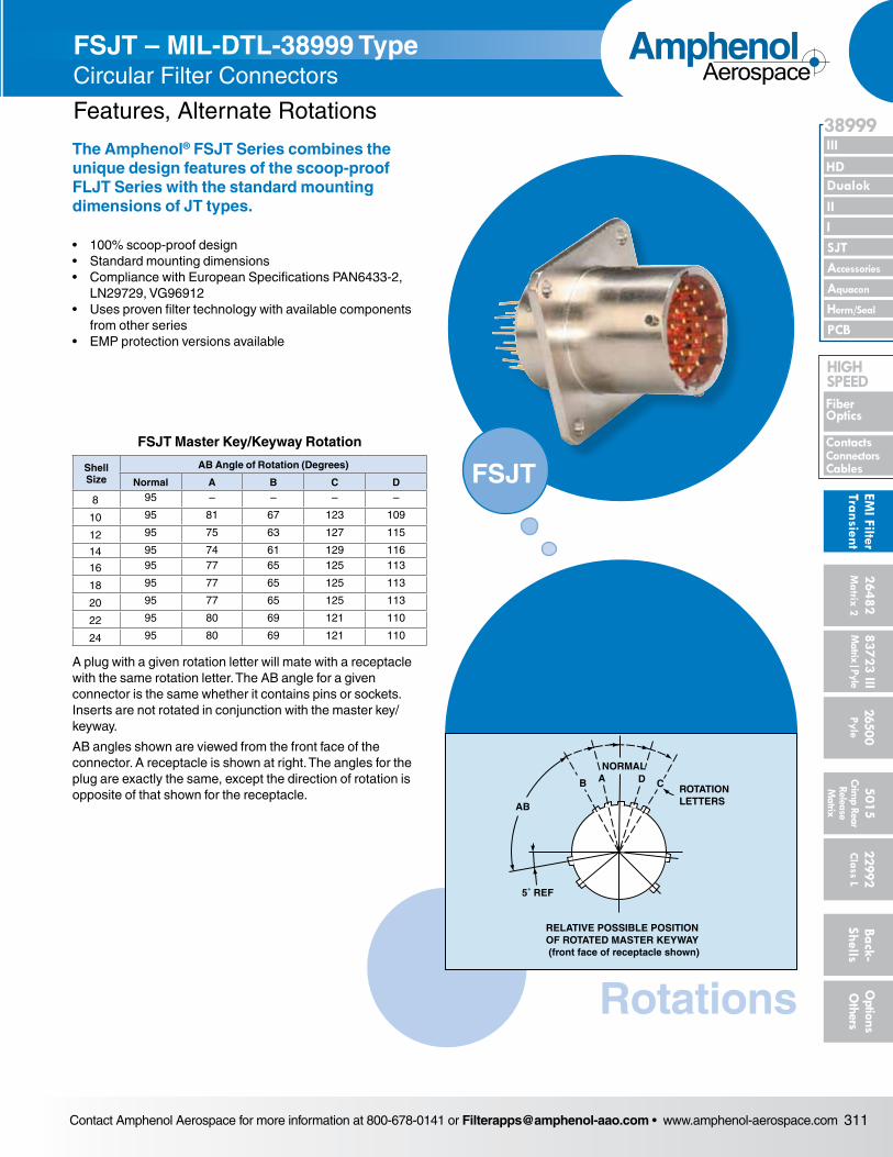
Contact Amphenol Aerospace for more information at 800-678-0141 or [email protected] • www.amphenol-aerospace.com 311
AmphenolAerospace
II Dualok
III
SJT
38999
I
PCB
Accessories
Aquacon
HD
EMI Filter
Transient
Herm/Seal
Fiber Optics
ContactsConnectorsCables
HIgH SPEED
26482M
atrix 2 83723 IIIM
atrix|Pyle5015
Crimp Rear
Release M
atrix
26500 Pyle
22992 C
lass L Back- Shells
Options
Others
The Amphenol® FSJT Series combines the unique design features of the scoop-proof FLJT Series with the standard mounting dimensions of JT types.
• 100% scoop-proof design• Standard mounting dimensions• Compliance with European Specifications PAN6433-2,
LN29729, VG96912• Uses proven filter technology with available components
from other series• EMP protection versions available
FSJT Master Key/Keyway Rotation
Shell Size
AB Angle of Rotation (Degrees)
Normal A B C D
8 95 – – – –
10 95 81 67 123 109
12 95 75 63 127 115
14 95 74 61 129 116
16 95 77 65 125 113
18 95 77 65 125 113
20 95 77 65 125 113
22 95 80 69 121 110
24 95 80 69 121 110
A plug with a given rotation letter will mate with a receptacle with the same rotation letter. The AB angle for a given connector is the same whether it contains pins or sockets. Inserts are not rotated in conjunc tion with the master key/keyway.
AB angles shown are viewed from the front face of the connector. A receptacle is shown at right. The angles for the plug are exactly the same, except the direction of rotation is opposite of that shown for the receptacle.
FSJT – MIL-DTL-38999 Type Circular Filter Connectors
Features, Alternate Rotations
FSJT
Rotations
RELATIVE POSSIBLE POSITIONOF ROTATED MASTER KEYWAY (front face of receptacle shown)
ROTATIONLETTERS
NORMAL
B A D C
AB
5˚ REF
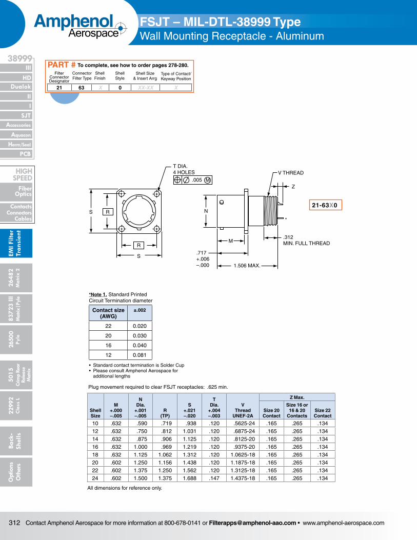
Contact Amphenol Aerospace for more information at 800-678-0141 or [email protected] • www.amphenol-aerospace.com312
AmphenolAerospace
Dualok
III
SJT
38999
PCB
HD
EMI F
ilter
Tran
sien
t
I II
Accessories
Herm/Seal
Aquacon
Fiber Optics
ContactsConnectors
Cables
HIgH SPEED
2648
2M
atrix
2
8372
3 III
5015
2650
0 Py
le
2299
2 C
lass
L
Back
- Sh
ells
Opt
ions
O
ther
sCr
imp
Rear
Rele
ase
Mat
rix
Mat
rix|P
yle
R
R
S
S
T DIA.4 HOLES
.005 M
1.506 MAX.
.717+.006–.000
N
M
V THREAD
Z
.312MIN. FULL THREAD
*
Plug movement required to clear FSJT receptacles: .625 min.
Shell Size
M +.000 –.005
N Dia.
+.001 –.005
R (TP)
S +.021 –.020
T Dia.
+.004 –.003
V Thread
UNEF-2A
Z Max.
Size 20 Contact
Size 16 or 16 & 20
ContactsSize 22 Contact
10 .632 .590 .719 .938 .120 .5625-24 .165 .265 .13412 .632 .750 .812 1.031 .120 .6875-24 .165 .265 .13414 .632 .875 .906 1.125 .120 .8125-20 .165 .265 .13416 .632 1.000 .969 1.219 .120 .9375-20 .165 .265 .13418 .632 1.125 1.062 1.312 .120 1.0625-18 .165 .265 .13420 .602 1.250 1.156 1.438 .120 1.1875-18 .165 .265 .13422 .602 1.375 1.250 1.562 .120 1.3125-18 .165 .265 .13424 .602 1.500 1.375 1.688 .147 1.4375-18 .165 .265 .134
All dimensions for reference only.
FSJT – MIL-DTL-38999 TypeWall Mounting Receptacle - Aluminum
21 63 X 0 XX-XX X
Filter Connector Designator
Connector Filter Type
Shell Finish
Shell Style
Shell Size& Insert Arrg
Type of Contact/Keyway Position
To complete, see how to order pages 278-280.PART #
21-63X0
*Note 1. Standard Printed Circuit Termination diameter
Contact size (AWG)
±.002
22 0.020
20 0.030
16 0.040
12 0.081
• Standard contact termination is Solder Cup• Please consult Amphenol Aerospace for additional lengths
Shell Size
D Dia.
±.005
M +.000 –.005
N Dia.
+.001 –.005
R (TP)
S +.021 –.020
T Dia.
+.004 –.003
V Thread
UNEF-2A
10 .427 .632 .590 .719 .938 .120 .6875-2412 .541 .632 .750 .812 1.031 .120 .8125-2014 .666 .632 .875 .906 1.125 .120 .9375-2016 .791 .632 1.000 .969 1.219 .120 1.0625-1818 .897 .632 1.125 1.062 1.312 .120 1.1875-1820 1.022 .602 1.250 1.156 1.438 .120 1.3125-1822 1.147 .602 1.375 1.250 1.562 .120 1.4375-1824 1.272 .602 1.500 1.375 1.688 .147 1.5625-18
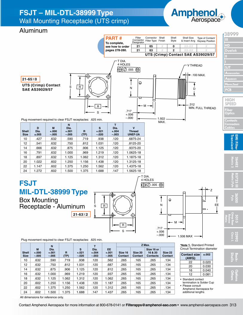
Contact Amphenol Aerospace for more information at 800-678-0141 or [email protected] • www.amphenol-aerospace.com 313
AmphenolAerospace
II Dualok
III
SJT
38999
I
PCB
Accessories
Aquacon
HD
EMI Filter
Transient
Herm/Seal
Fiber Optics
ContactsConnectorsCables
HIgH SPEED
26482M
atrix 2 83723 IIIM
atrix|Pyle5015
Crimp Rear
Release M
atrix
26500 Pyle
22992 C
lass L Back- Shells
Options
Others
FSJT – MIL-DTL-38999 TypeWall Mounting Receptacle - Aluminum
R
R
S
S
.005 M
T DIA. 4 HOLES
N
1.922 MAX.
.717+.006–.000
V THREAD
.100 MAX.
D
M .312MIN. FULL THREAD
Plug movement required to clear FSJT receptacles: .625 min.
Shell Size
D Dia.
±.005
M +.000 –.005
N Dia.
+.001 –.005
R (TP)
S +.021 –.020
T Dia.
+.004 –.003
V Thread
UNEF-2A
10 .427 .632 .590 .719 .938 .120 .6875-2412 .541 .632 .750 .812 1.031 .120 .8125-2014 .666 .632 .875 .906 1.125 .120 .9375-2016 .791 .632 1.000 .969 1.219 .120 1.0625-1818 .897 .632 1.125 1.062 1.312 .120 1.1875-1820 1.022 .602 1.250 1.156 1.438 .120 1.3125-1822 1.147 .602 1.375 1.250 1.562 .120 1.4375-1824 1.272 .602 1.500 1.375 1.688 .147 1.5625-18
21-65X0
UTS (Crimp) ContactSAE AS39029/57
R
R
S
S
.005 M
T DIA. 4 HOLES
EE
Z
N
M
1.506 MAX
.717+.006–.000
*
Plug movement required to clear FSJT receptacles: .625 min.
Shell Size
M +.000 –.005
N Dia.
+.001 –.005
R (TP)
S +.021 –.020
T Dia.
+.004 –.003
EE +.001 –.005
Z Max.
Size 16 Contact
Size 20 Contact
Size 16 or 16 & 20
ContactsSize 22 Contact
10 .632 .590 .719 .938 .120 .562 .265 .165 .265 .13412 .632 .750 .812 1.031 .120 .687 .265 .165 .265 .13414 .632 .875 .906 1.125 .120 .812 .265 .165 .265 .13416 .632 1.000 .969 1.219 .120 .937 .265 .165 .265 .13418 .632 1.125 1.062 1.312 .120 1.062 .265 .165 .265 .13420 .602 1.250 1.156 1.438 .120 1.187 .265 .165 .265 .13422 .602 1.375 1.250 1.562 .120 1.312 .265 .165 .265 .13424 .602 1.500 1.375 1.688 .147 1.437 .265 .165 .265 .134
All dimensions for reference only.
21-63X2
FSJT – MIL-DTL-38999 TypeWall Mounting Receptacle (UTS crimp)
Aluminum
FSJT MIL-DTL-38999 TypeBox Mounting Receptacle - Aluminum
21 65 X 0 XX-XX X21 63 X 2 XX-XX X
Filter Connector Designator
Connector Filter Type
Shell Finish
Shell Style
Shell Size& Insert Arrg
Type of Contact/Keyway Position
To complete, see how to order pages 278-280.
PART #
UTS (Crimp) Contact SAE AS39029/57
Contact size (AWG)
±.002
22 0.02020 0.03016 0.04012 0.081
*Note 1. Standard Printed Circuit Termination diameter
• Standard contact termination is Solder Cup• Please consult Amphenol Aerospace for additional lengths
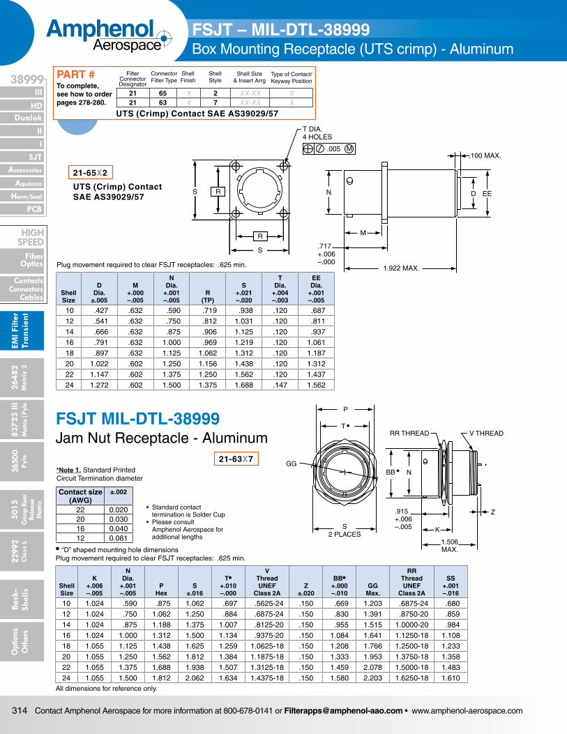
Contact Amphenol Aerospace for more information at 800-678-0141 or [email protected] • www.amphenol-aerospace.com314
AmphenolAerospace
Dualok
III
SJT
38999
PCB
HD
EMI F
ilter
Tran
sien
t
I II
Accessories
Herm/Seal
Aquacon
Fiber Optics
ContactsConnectors
Cables
HIgH SPEED
2648
2M
atrix
2
8372
3 III
5015
2650
0 Py
le
2299
2 C
lass
L
Back
- Sh
ells
Opt
ions
O
ther
sCr
imp
Rear
Rele
ase
Mat
rix
Mat
rix|P
yle
R
R
S
S
.005 M
T DIA. 4 HOLES
N
.717+.006–.000
M
1.922 MAX.
D EE
.100 MAX.
Plug movement required to clear FSJT receptacles: .625 min.
Shell Size
D Dia.
±.005
M +.000 –.005
N Dia.
+.001 –.005
R (TP)
S +.021 –.020
T Dia.
+.004 –.003
EE Dia.
+.001 –.005
10 .427 .632 .590 .719 .938 .120 .68712 .541 .632 .750 .812 1.031 .120 .81114 .666 .632 .875 .906 1.125 .120 .93716 .791 .632 1.000 .969 1.219 .120 1.06118 .897 .632 1.125 1.062 1.312 .120 1.18720 1.022 .602 1.250 1.156 1.438 .120 1.31222 1.147 .602 1.375 1.250 1.562 .120 1.43724 1.272 .602 1.500 1.375 1.688 .147 1.562
P
S2 PLACES
GG
T •RR THREAD V THREAD
Z
K
1.506MAX.
N
.915+.006–.005
BB •*
• “D” shaped mounting hole dimensionsPlug movement required to clear FSJT receptacles: .625 min.
Shell Size
K +.006 –.005
N Dia.
+.001 –.005
P Hex
S ±.016
T• +.010 –.000
V Thread UNEF
Class 2AZ
±.020
BB• +.000 –.010
GG Max.
RR Thread UNEF
Class 2A
SS +.001 –.016
10 1.024 .590 .875 1.062 .697 .5625-24 .150 .669 1.203 .6875-24 .68012 1.024 .750 1.062 1.250 .884 .6875-24 .150 .830 1.391 .8750-20 .85914 1.024 .875 1.188 1.375 1.007 .8125-20 .150 .955 1.515 1.0000-20 .98416 1.024 1.000 1.312 1.500 1.134 .9375-20 .150 1.084 1.641 1.1250-18 1.10818 1.055 1.125 1.438 1.625 1.259 1.0625-18 .150 1.208 1.766 1.2500-18 1.23320 1.055 1.250 1.562 1.812 1.384 1.1875-18 .150 1.333 1.953 1.3750-18 1.35822 1.055 1.375 1.688 1.938 1.507 1.3125-18 .150 1.459 2.078 1.5000-18 1.48324 1.055 1.500 1.812 2.062 1.634 1.4375-18 .150 1.580 2.203 1.6250-18 1.610
All dimensions for reference only.
21-63X7
FSJT – MIL-DTL-38999Box Mounting Receptacle (UTS crimp) - Aluminum
FSJT MIL-DTL-38999Jam Nut Receptacle - Aluminum
21-65X2
UTS (Crimp) ContactSAE AS39029/57
21 65 X 2 XX-XX X21 63 X 7 XX-XX X
Filter Connector Designator
Connector Filter Type
Shell Finish
Shell Style
Shell Size& Insert Arrg
Type of Contact/Keyway Position
To complete, see how to order pages 278-280.
PART #
UTS (Crimp) Contact SAE AS39029/57
Contact size (AWG)
±.002
22 0.02020 0.03016 0.04012 0.081
*Note 1. Standard Printed Circuit Termination diameter
• Standard contact termination is Solder Cup• Please consult Amphenol Aerospace for additional lengths
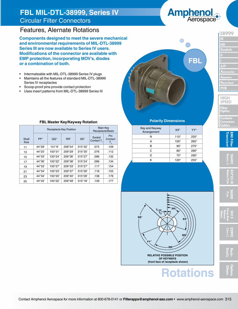
Contact Amphenol Aerospace for more information at 800-678-0141 or [email protected] • www.amphenol-aerospace.com 315
AmphenolAerospace
II Dualok
III
SJT
38999
I
PCB
Accessories
Aquacon
HD
EMI Filter
Transient
Herm/Seal
Fiber Optics
ContactsConnectorsCables
HIgH SPEED
26482M
atrix 2 83723 IIIM
atrix|Pyle5015
Crimp Rear
Release M
atrix
26500 Pyle
22992 C
lass L Back- Shells
Options
Others
FSJT – MIL-DTL-38999Box Mounting Receptacle (UTS crimp) - Aluminum
FBL MIL-DTL-38999, Series IV Circular Filter Connectors
Features, Alernate RotationsComponents designed to meet the severe mechanical and environmental requirements of MIL-DTL-38999 Series III are now available to Series IV users. Modifications of the con nector are available with EMP protection, incorporating MOV’s, diodes or a combination of both.
• Intermateable with MIL-DTL-38999 Series IV plugs• Maintains all the features of standard MIL-DTL-38999
Series IV receptacles• Scoop-proof pins provide contact protection• Uses insert patterns from MIL-DTL-38999 Series III
Rotations
orT1T2
PP˚
XX˚
QQ˚
RELATIVE POSSIBLE POSITIONOF KEYWAYS
(front face of receptacle shown)
RR˚
YY˚
SS˚
FBL
Polarity Dimensions
Key and Keyway Arrangement
XX° YY°
N 110° 250°
A 100° 260°
B 90° 270°
C 80° 280°
D 70° 290°
K 120° 255°
FBL Master Key/Keyway Rotation
Shell Size
Receptacle Key Position Main Key Receptacle/Basic
PP° QQ° RR° SS° Socket Contact T1
Pin Contact
T2
11 44°28’ 151°6’ 208°54’ 315°32’ .075 .109
13 44°25’ 150°31’ 209°29’ 315°35’ .076 .112
15 44°33’ 150°24’ 209°36’ 315°27’ .096 .132
17 44°36’ 150°22’ 209°38’ 315°24’ .096 .134
19 44°33’ 150°27’ 209°33’ 315°27’ .117 .154
21 44°34’ 150°23’ 209°37’ 315°26’ .118 .155
23 44°34’ 150°20’ 209°40’ 315°26’ .138 .176
25 44°42’ 150°22’ 209°48’ 315°18’ .139 .177
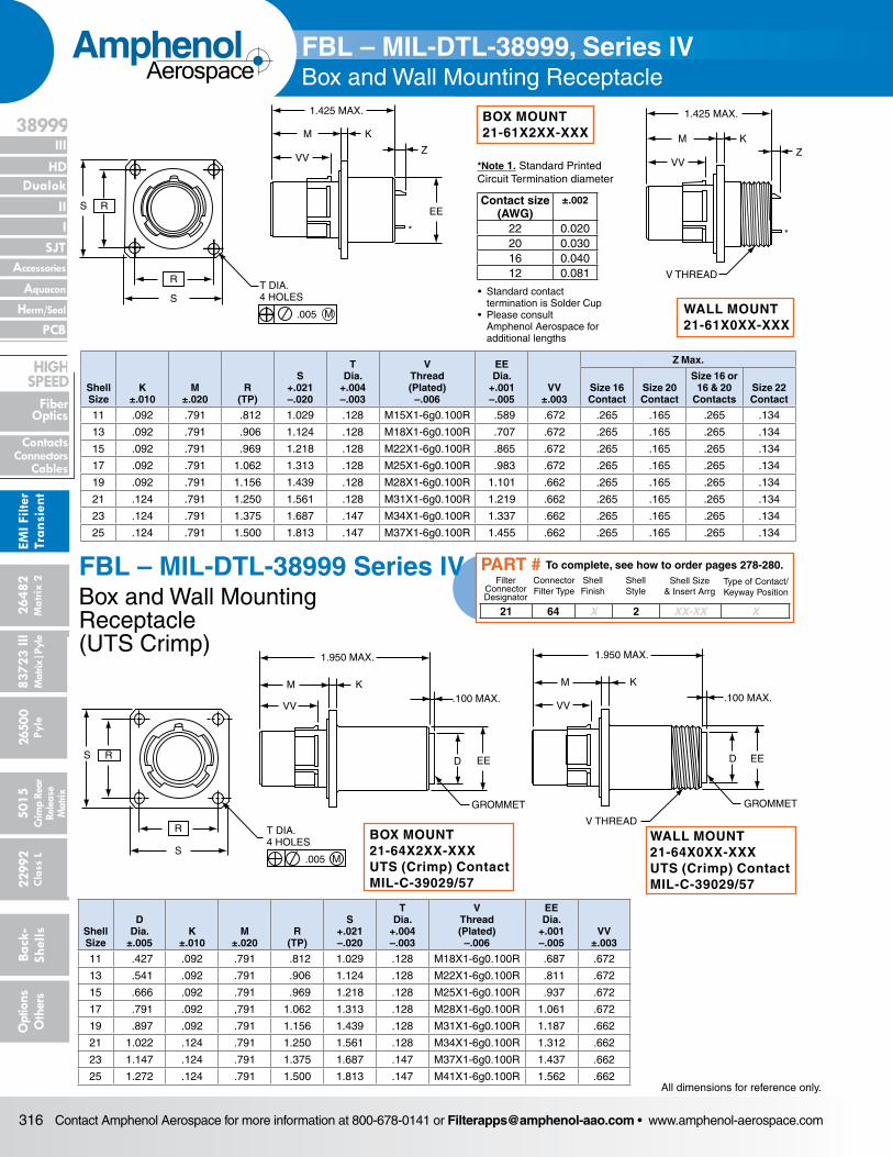
Contact Amphenol Aerospace for more information at 800-678-0141 or [email protected] • www.amphenol-aerospace.com316
AmphenolAerospace
Dualok
III
SJT
38999
PCB
HD
EMI F
ilter
Tran
sien
t
I II
Accessories
Herm/Seal
Aquacon
Fiber Optics
ContactsConnectors
Cables
HIgH SPEED
2648
2M
atrix
2
8372
3 III
5015
2650
0 Py
le
2299
2 C
lass
L
Back
- Sh
ells
Opt
ions
O
ther
sCr
imp
Rear
Rele
ase
Mat
rix
Mat
rix|P
yle
S R
S
RT DIA.4 HOLES
.005 M
1.425 MAX.
M K
ZVV
1.425 MAX.
M KZ
VV
EE
*
*
V THREAD
Shell Size
K ±.010
M ±.020
R (TP)
S +.021 –.020
T Dia.
+.004 –.003
V Thread (Plated)
–.006
EE Dia.
+.001 –.005
VV ±.003
Z Max.
Size 16 Contact
Size 20 Contact
Size 16 or 16 & 20
ContactsSize 22 Contact
11 .092 .791 .812 1.029 .128 M15X1-6g0.100R .589 .672 .265 .165 .265 .134
13 .092 .791 .906 1.124 .128 M18X1-6g0.100R .707 .672 .265 .165 .265 .134
15 .092 .791 .969 1.218 .128 M22X1-6g0.100R .865 .672 .265 .165 .265 .134
17 .092 .791 1.062 1.313 .128 M25X1-6g0.100R .983 .672 .265 .165 .265 .134
19 .092 .791 1.156 1.439 .128 M28X1-6g0.100R 1.101 .662 .265 .165 .265 .134
21 .124 .791 1.250 1.561 .128 M31X1-6g0.100R 1.219 .662 .265 .165 .265 .134
23 .124 .791 1.375 1.687 .147 M34X1-6g0.100R 1.337 .662 .265 .165 .265 .134
25 .124 .791 1.500 1.813 .147 M37X1-6g0.100R 1.455 .662 .265 .165 .265 .134
BOX MOUNT21-61X2XX-XXX
FBL – MIL-DTL-38999, Series IVBox and Wall Mounting Receptacle
S R
S
RT DIA.4 HOLES
.005 M
1.425 MAX.
M K
ZVV
1.425 MAX.
M KZ
VV
EE
*
*
V THREAD
R
S
RS
T DIA.4 HOLES
.005 M
1.950 MAX.
K
VV.100 MAX.
D EE
GROMMET
GROMMET
V THREAD
M
1.950 MAX.
K
VV.100 MAX.
D EE
MShell Size
D Dia.
±.005K
±.010M
±.020R
(TP)
S +.021 –.020
T Dia.
+.004 –.003
V Thread (Plated)
–.006
EE Dia.
+.001 –.005
VV ±.003
11 .427 .092 .791 .812 1.029 .128 M18X1-6g0.100R .687 .672
13 .541 .092 .791 .906 1.124 .128 M22X1-6g0.100R .811 .672
15 .666 .092 .791 .969 1.218 .128 M25X1-6g0.100R .937 .672
17 .791 .092 ,791 1.062 1.313 .128 M28X1-6g0.100R 1.061 .672
19 .897 .092 .791 1.156 1.439 .128 M31X1-6g0.100R 1.187 .662
21 1.022 .124 .791 1.250 1.561 .128 M34X1-6g0.100R 1.312 .662
23 1.147 .124 .791 1.375 1.687 .147 M37X1-6g0.100R 1.437 .662
25 1.272 .124 .791 1.500 1.813 .147 M41X1-6g0.100R 1.562 .662
BOX MOUNT21-64X2XX-XXXUTS (Crimp) ContactMIL-C-39029/57
FBL – MIL-DTL-38999 Series IVBox and Wall Mounting Receptacle (UTS Crimp)
R
S
RS
T DIA.4 HOLES
.005 M
1.950 MAX.
K
VV.100 MAX.
D EE
GROMMET
GROMMET
V THREAD
M
1.950 MAX.
K
VV.100 MAX.
D EE
M
WALL MOUNT21-64X0XX-XXXUTS (Crimp) ContactMIL-C-39029/57
21 64 X 2 XX-XX X
Filter Connector Designator
Connector Filter Type
Shell Finish
Shell Style
Shell Size& Insert Arrg
Type of Contact/Keyway Position
To complete, see how to order pages 278-280.PART #
WALL MOUNT21-61X0XX-XXX
All dimensions for reference only.
Contact size (AWG)
±.002
22 0.02020 0.03016 0.04012 0.081
*Note 1. Standard Printed Circuit Termination diameter
• Standard contact termination is Solder Cup• Please consult Amphenol Aerospace for additional lengths
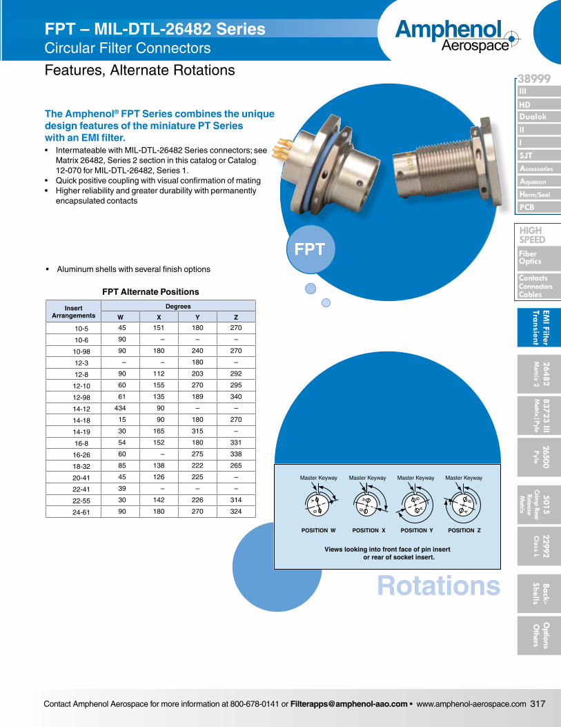
Contact Amphenol Aerospace for more information at 800-678-0141 or [email protected] • www.amphenol-aerospace.com 317
AmphenolAerospace
II Dualok
III
SJT
38999
I
PCB
Accessories
Aquacon
HD
EMI Filter
Transient
Herm/Seal
Fiber Optics
ContactsConnectorsCables
HIgH SPEED
26482M
atrix 2 83723 IIIM
atrix|Pyle5015
Crimp Rear
Release M
atrix
26500 Pyle
22992 C
lass L Back- Shells
Options
Others
FPT – MIL-DTL-26482 SeriesCircular Filter Connectors
Features, Alternate Rotations
The Amphenol® FPT Series combines the unique design features of the miniature PT Series with an EMI filter.• Intermateable with MIL-DTL-26482 Series connectors; see
Matrix 26482, Series 2 section in this catalog or Catalog 12-070 for MIL-DTL-26482, Series 1.
• Quick positive coupling with visual confirmation of mating• Higher reliability and greater durability with permanently
encapsulated contacts
FPT • Aluminum shells with several finish options
FPT Alternate Positions
Insert Arrangements
Degrees
W X Y Z
10-5 45 151 180 270
10-6 90 – – –
10-98 90 180 240 270
12-3 – – 180 –
12-8 90 112 203 292
12-10 60 155 270 295
12-98 61 135 189 340
14-12 434 90 – –
14-18 15 90 180 270
14-19 30 165 315 –
16-8 54 152 180 331
16-26 60 – 275 338
18-32 85 138 222 265
20-41 45 126 225 –
22-41 39 – – –
22-55 30 142 226 314
24-61 90 180 270 324
Rotations
AB
Master Keyway
POSITION W
Master Keyway
POSITION X
Master Keyway
POSITION Y
Master Keyway
POSITION Z
Views looking into front face of pin insert or rear of socket insert.
AB A
B
BA
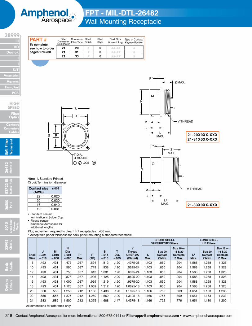
Contact Amphenol Aerospace for more information at 800-678-0141 or [email protected] • www.amphenol-aerospace.com318
AmphenolAerospace
Dualok
III
SJT
38999
PCB
HD
EMI F
ilter
Tran
sien
t
I II
Accessories
Herm/Seal
Aquacon
Fiber Optics
ContactsConnectors
Cables
HIgH SPEED
2648
2M
atrix
2
8372
3 III
5015
2650
0 Py
le
2299
2 C
lass
L
Back
- Sh
ells
Opt
ions
O
ther
sCr
imp
Rear
Rele
ase
Mat
rix
Mat
rix|P
yle
S R
S
R
T DIA.4 HOLES
.005 M
Z MAX.
N
LMAX.
M
J
V THREAD
M
J
ZMAX.
N
V THREAD
P*
P*
LMAX.
1
*
*
FPT - MIL-DTL-26482Wall Mounting Receptacle
Plug movement required to clear FPT receptacles: .438 min.* Acceptable panel thickness for back panel mounting a standard receptacle.
Shell Size
J +.021 –.010
M +.010 –.000
N Dia
+.001 –.005
P* Max.
R (TP)
S +.011 –.010
T Dia.
±.005
V Thread
UNEF-2A (Plated)
SHORT SHELL VHF/UHF/MF Filters
LONG SHELL HF Filters
L Max.
Size 20 Contact Z Max.
Size 16 or 16 & 20
Contacts Z Max.
L1
Max.
Size 20 Contact Z Max.
Size 16 or 16 & 20
Contacts Z Max.
8 .493 .431 .473 .087 .594 .812 .120 .4375-28 1.103 .850 .904 1.588 1.258 1.328
10 .493 .431 .590 .087 .719 .938 .120 .5625-24 1.103 .850 .904 1.588 1.258 1.328
12 .493 .431 .750 .087 .812 1.031 .120 .6875-24 1.103 .850 .904 1.588 1.258 1.328
14 .493 .431 .875 .087 .906 1.125 .120 .8125-20 1.103 .850 .904 1.588 1.258 1.328
16 .493 .431 1.000 .087 .969 1.219 .120 .9375-20 1.103 .850 .904 1.588 1.258 1.328
18 .493 .431 1.125 .087 1.062 1.312 .120 1.0625-18 1.103 .850 .904 1.588 1.258 1.328
20 .650 .556 1.250 .212 1.156 1.438 .120 1.1875-18 1.166 .755 .809 1.651 1.163 1.233
22 .650 .556 1.375 .212 1.250 1.562 .120 1.3125-18 1.166 .755 .809 1.651 1.163 1.233
24 .683 .589 1.500 .212 1.375 1.688 .147 1.4375-18 1.166 .722 .776 1.651 1.130 1.200
All dimensions for reference only.
21-20X0XX-XXX21-31X0XX-XXX
21-33X0XX-XXX
21 20 X 0 XX-XX X21 31 X 0 XX-XX X21 33 X 0 XX-XX X
Filter Connector Designator
Connector Filter Type
Shell Finish
Shell Style
Shell Size& Insert Arrg
Type of Contact/Keyway Position
To complete, see how to order pages 278-280.
PART #
Contact size (AWG)
±.002
22 0.02020 0.03016 0.04012 0.081
*Note 1. Standard Printed Circuit Termination diameter
• Standard contact termination is Solder Cup• Please consult Amphenol Aerospace for additional lengths
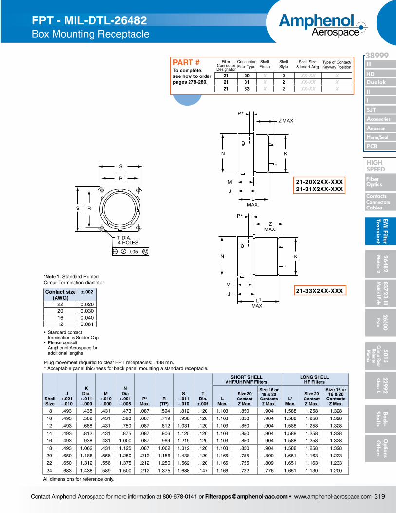
Contact Amphenol Aerospace for more information at 800-678-0141 or [email protected] • www.amphenol-aerospace.com 319
AmphenolAerospace
II Dualok
III
SJT
38999
I
PCB
Accessories
Aquacon
HD
EMI Filter
Transient
Herm/Seal
Fiber Optics
ContactsConnectorsCables
HIgH SPEED
26482M
atrix 2 83723 IIIM
atrix|Pyle5015
Crimp Rear
Release M
atrix
26500 Pyle
22992 C
lass L Back- Shells
Options
Others
RS
T DIA.4 HOLES
.005
S
R
M
Z MAX.
KN
M
J
LMAX.
P*
ZMAX.
KN
M
JL
MAX.1
*P
*
*
FPT - MIL-DTL-26482Box Mounting Receptacle
Plug movement required to clear FPT receptacles: .438 min.* Acceptable panel thickness for back panel mounting a standard receptacle.
Shell Size
J +.021 –.010
K Dia.
+.011 –.000
M +.010 –.000
N Dia
+.001 –.005
P* Max.
R (TP)
S +.011 –.010
T Dia.
±.005
SHORT SHELL VHF/UHF/MF Filters
LONG SHELL HF Filters
L Max.
Size 20 Contact Z Max.
Size 16 or 16 & 20
Contacts Z Max.
L1
Max.
Size 20 Contact Z Max.
Size 16 or 16 & 20
Contacts Z Max.
8 .493 .438 .431 .473 .087 .594 .812 .120 1.103 .850 .904 1.588 1.258 1.328
10 .493 .562 .431 .590 .087 .719 .938 .120 1.103 .850 .904 1.588 1.258 1.328
12 .493 .688 .431 .750 .087 .812 1.031 .120 1.103 .850 .904 1.588 1.258 1.328
14 .493 .812 .431 .875 .087 .906 1.125 .120 1.103 .850 .904 1.588 1.258 1.328
16 .493 .938 .431 1.000 .087 .969 1.219 .120 1.103 .850 .904 1.588 1.258 1.328
18 .493 1.062 .431 1.125 .087 1.062 1.312 .120 1.103 .850 .904 1.588 1.258 1.328
20 .650 1.188 .556 1.250 .212 1.156 1.438 .120 1.166 .755 .809 1.651 1.163 1.233
22 .650 1.312 .556 1.375 .212 1.250 1.562 .120 1.166 .755 .809 1.651 1.163 1.233
24 .683 1.438 .589 1.500 .212 1.375 1.688 .147 1.166 .722 .776 1.651 1.130 1.200
All dimensions for reference only.
21-20X2XX-XXX21-31X2XX-XXX
21-33X2XX-XXX
21 20 X 2 XX-XX X21 31 X 2 XX-XX X21 33 X 2 XX-XX X
Filter Connector Designator
Connector Filter Type
Shell Finish
Shell Style
Shell Size& Insert Arrg
Type of Contact/Keyway Position
To complete, see how to order pages 278-280.
PART #
Contact size (AWG)
±.002
22 0.02020 0.03016 0.04012 0.081
*Note 1. Standard Printed Circuit Termination diameter
• Standard contact termination is Solder Cup• Please consult Amphenol Aerospace for additional lengths
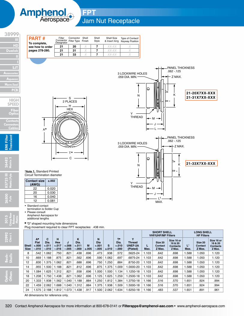
Contact Amphenol Aerospace for more information at 800-678-0141 or [email protected] • www.amphenol-aerospace.com320
AmphenolAerospace
Dualok
III
SJT
38999
PCB
HD
EMI F
ilter
Tran
sien
t
I II
Accessories
Herm/Seal
Aquacon
Fiber Optics
ContactsConnectors
Cables
HIgH SPEED
2648
2M
atrix
2
8372
3 III
5015
2650
0 Py
le
2299
2 C
lass
L
Back
- Sh
ells
Opt
ions
O
ther
sCr
imp
Rear
Rele
ase
Mat
rix
Mat
rix|P
yle
S2 PLACES
HHEX
C
A•
T •
3 LOCKWIRE HOLES.059 DIA. MIN.
PANEL THICKNESS.062 -.125
KN
YTHREAD M
J
L
Z MAX.
3 LOCKWIRE HOLES.059 DIA. MIN.
PANEL THICKNESS.062 -.125
KN
YTHREAD M
J
LMAX.
Z MAX.
1
*
*
FPTJam Nut Receptacle
• “D” shaped mounting hole dimensionsPlug movement required to clear FPT receptacles: .438 min.
Shell Size
A• Flat
+.000 –.010
C Dia.
+.011 –.010
HHex
+.017 –.016
J +.006 –.005
K Dia.
+.011 –.000
M ±.005
N Dia
+.001 –.005
S ±.010
T• Dia.
+.010 –.000
Y Thread
UNEF-2A (Plated)
SHORT SHELL VHF/UHF/MF Filters
LONG SHELL HF Filters
L Max.
Size 20 Contact Z Max.
Size 16 or 16 & 20
Contacts Z Max.
L1
Max.
Size 20 Contact Z Max.
Size 16 or 16 & 20
Contacts Z Max.
8 .542 1.062 .750 .821 .438 .696 .473 .938 .572 .5625-24 1.103 .642 .698 1.588 1.050 1.120
10 .669 1.188 .875 .821 .562 .696 .590 1.062 .697 .6875-24 1.103 .642 .698 1.588 1.050 1.120
12 .830 1.375 1.062 .821 .688 .696 .750 1.250 .884 .8750-20 1.103 .642 .698 1.588 1.050 1.120
14 .955 1.500 1.188 .821 .812 .696 .875 1.375 1.009 1.0000-20 1.103 .642 .698 1.588 1.050 1.120
16 1.084 1.625 1.312 .821 .938 .696 1.000 1.500 1.134 1.1250-18 1.103 .642 .698 1.588 1.050 1.120
18 1.208 1.750 1.438 .821 1.062 .696 1.125 1.625 1.259 1.2500-18 1.103 .642 .698 1.588 1.050 1.120
20 1.333 1.938 1.562 1.040 1.188 .884 1.250 1.812 1.384 1.3750-18 1.166 .516 .570 1.651 .924 .994
22 1.459 2.062 1.688 1.040 1.312 .884 1.375 1.938 1.509 1.5000-18 1.166 .516 .570 1.651 .924 .994
24 1.575 2.188 1.812 1.073 1.438 .917 1.500 2.062 1.634 1.6250-18 1.166 .483 .537 1.651 .891 .961
All dimensions for reference only.
21-20X7XX-XXX21-31X7XX-XXX
21-33X7XX-XXX
21 20 X 7 XX-XX X21 31 X 7 XX-XX X21 33 X 7 XX-XX X
Filter Connector Designator
Connector Filter Type
Shell Finish
Shell Style
Shell Size& Insert Arrg
Type of Contact/Keyway Position
To complete, see how to order pages 278-280.
PART #
Contact size (AWG)
±.002
22 0.02020 0.03016 0.04012 0.081
*Note 1. Standard Printed Circuit Termination diameter
• Standard contact termination is Solder Cup• Please consult Amphenol Aerospace for additional lengths
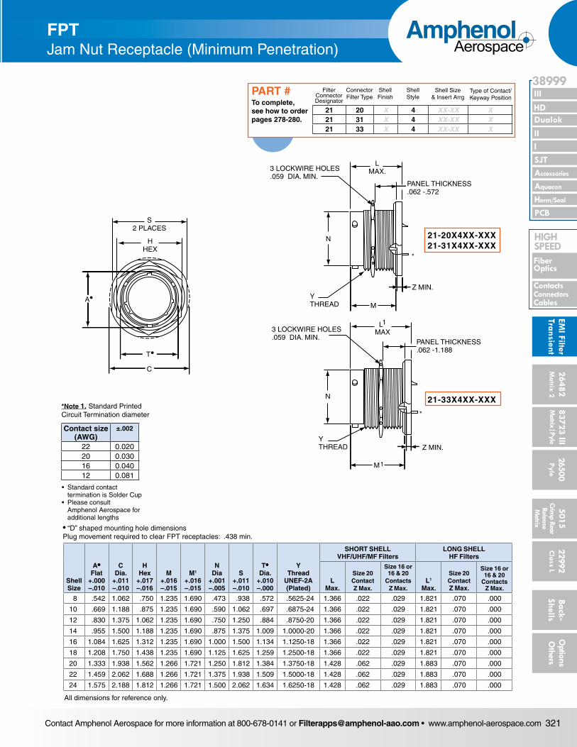
Contact Amphenol Aerospace for more information at 800-678-0141 or [email protected] • www.amphenol-aerospace.com 321
AmphenolAerospace
II Dualok
III
SJT
38999
I
PCB
Accessories
Aquacon
HD
EMI Filter
Transient
Herm/Seal
Fiber Optics
ContactsConnectorsCables
HIgH SPEED
26482M
atrix 2 83723 IIIM
atrix|Pyle5015
Crimp Rear
Release M
atrix
26500 Pyle
22992 C
lass L Back- Shells
Options
Others
N
3 LOCKWIRE HOLES.059 DIA. MIN.
PANEL THICKNESS.062 -.572
LMAX.
YTHREAD M
Z MIN.
*
*
N
3 LOCKWIRE HOLES.059 DIA. MIN.
PANEL THICKNESS.062 -1.188
L
YTHREAD Z MIN.
M1
MAX1
S2 PLACES
HHEX
C
A•
T•
FPTJam Nut Receptacle (Minimum Penetration)
• “D” shaped mounting hole dimensionsPlug movement required to clear FPT receptacles: .438 min.
Shell Size
A• Flat
+.000 –.010
C Dia.
+.011 –.010
HHex
+.017 –.016
M +.016 –.015
M1
+.016 –.015
N Dia
+.001 –.005
S +.011 –.010
T• Dia.
+.010 –.000
Y Thread
UNEF-2A (Plated)
SHORT SHELL VHF/UHF/MF Filters
LONG SHELL HF Filters
L Max.
Size 20 Contact Z Max.
Size 16 or 16 & 20
Contacts Z Max.
L1
Max.
Size 20 Contact Z Max.
Size 16 or 16 & 20
Contacts Z Max.
8 .542 1.062 .750 1.235 1.690 .473 .938 .572 .5625-24 1.366 .022 .029 1.821 .070 .000
10 .669 1.188 .875 1.235 1.690 .590 1.062 .697 .6875-24 1.366 .022 .029 1.821 .070 .000
12 .830 1.375 1.062 1.235 1.690 .750 1.250 .884 .8750-20 1.366 .022 .029 1.821 .070 .000
14 .955 1.500 1.188 1.235 1.690 .875 1.375 1.009 1.0000-20 1.366 .022 .029 1.821 .070 .000
16 1.084 1.625 1.312 1.235 1.690 1.000 1.500 1.134 1.1250-18 1.366 .022 .029 1.821 .070 .000
18 1.208 1.750 1.438 1.235 1.690 1.125 1.625 1.259 1.2500-18 1.366 .022 .029 1.821 .070 .000
20 1.333 1.938 1.562 1.266 1.721 1.250 1.812 1.384 1.3750-18 1.428 .062 .029 1.883 .070 .000
22 1.459 2.062 1.688 1.266 1.721 1.375 1.938 1.509 1.5000-18 1.428 .062 .029 1.883 .070 .000
24 1.575 2.188 1.812 1.266 1.721 1.500 2.062 1.634 1.6250-18 1.428 .062 .029 1.883 .070 .000
All dimensions for reference only.
21-20X4XX-XXX21-31X4XX-XXX
21-33X4XX-XXX
21 20 X 4 XX-XX X21 31 X 4 XX-XX X21 33 X 4 XX-XX X
Filter Connector Designator
Connector Filter Type
Shell Finish
Shell Style
Shell Size& Insert Arrg
Type of Contact/Keyway Position
To complete, see how to order pages 278-280.
PART #
Contact size (AWG)
±.002
22 0.02020 0.03016 0.04012 0.081
*Note 1. Standard Printed Circuit Termination diameter
• Standard contact termination is Solder Cup• Please consult Amphenol Aerospace for additional lengths
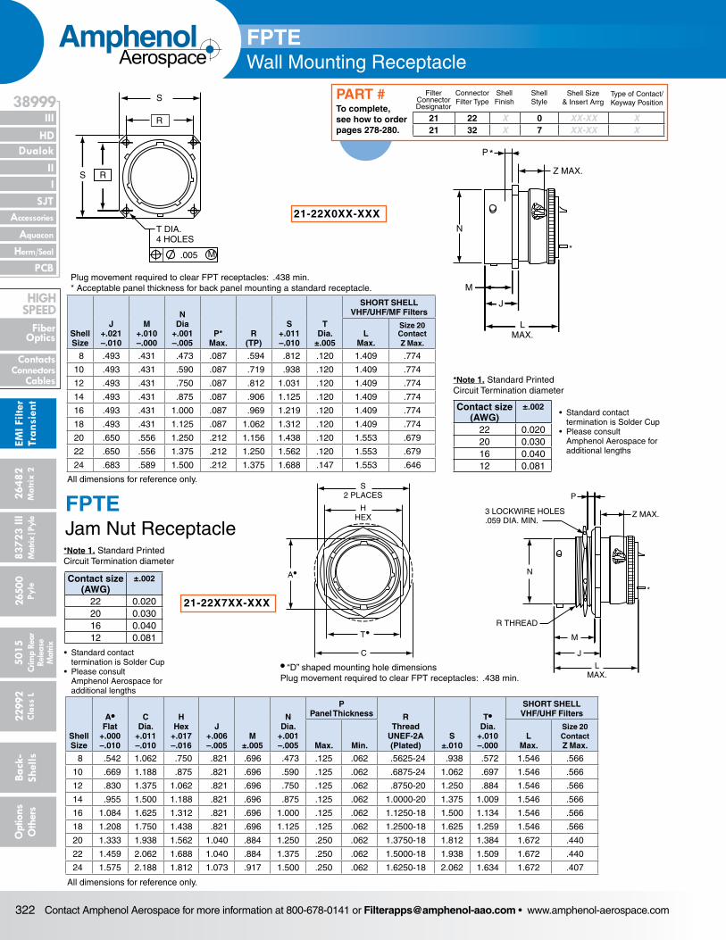
Contact Amphenol Aerospace for more information at 800-678-0141 or [email protected] • www.amphenol-aerospace.com322
AmphenolAerospace
Dualok
III
SJT
38999
PCB
HD
EMI F
ilter
Tran
sien
t
I II
Accessories
Herm/Seal
Aquacon
Fiber Optics
ContactsConnectors
Cables
HIgH SPEED
2648
2M
atrix
2
8372
3 III
5015
2650
0 Py
le
2299
2 C
lass
L
Back
- Sh
ells
Opt
ions
O
ther
sCr
imp
Rear
Rele
ase
Mat
rix
Mat
rix|P
yle
RS
T DIA.4 HOLES
.005
S
R
M
Z MAX.
N
M
J
LMAX.
P*
*
FPTEWall Mounting Receptacle
Plug movement required to clear FPT receptacles: .438 min.* Acceptable panel thickness for back panel mounting a standard receptacle.
All dimensions for reference only.
N
3 LOCKWIRE HOLES.059 DIA. MIN.
P
Z MAX.
R THREAD
M
J
LMAX.
*
S2 PLACES
HHEX
C
A•
T•
FPTEJam Nut Receptacle
• “D” shaped mounting hole dimensionsPlug movement required to clear FPT receptacles: .438 min.
Shell Size
A• Flat
+.000 –.010
C Dia.
+.011 –.010
HHex
+.017 –.016
J +.006 –.005
M ±.005
N Dia.
+.001 –.005
P Panel Thickness R
Thread UNEF-2A (Plated)
S ±.010
T• Dia.
+.010 –.000
SHORT SHELL VHF/UHF Filters
Max. Min.L
Max.
Size 20 Contact Z Max.
8 .542 1.062 .750 .821 .696 .473 .125 .062 .5625-24 .938 .572 1.546 .566
10 .669 1.188 .875 .821 .696 .590 .125 .062 .6875-24 1.062 .697 1.546 .566
12 .830 1.375 1.062 .821 .696 .750 .125 .062 .8750-20 1.250 .884 1.546 .566
14 .955 1.500 1.188 .821 .696 .875 .125 .062 1.0000-20 1.375 1.009 1.546 .566
16 1.084 1.625 1.312 .821 .696 1.000 .125 .062 1.1250-18 1.500 1.134 1.546 .566
18 1.208 1.750 1.438 .821 .696 1.125 .125 .062 1.2500-18 1.625 1.259 1.546 .566
20 1.333 1.938 1.562 1.040 .884 1.250 .250 .062 1.3750-18 1.812 1.384 1.672 .440
22 1.459 2.062 1.688 1.040 .884 1.375 .250 .062 1.5000-18 1.938 1.509 1.672 .440
24 1.575 2.188 1.812 1.073 .917 1.500 .250 .062 1.6250-18 2.062 1.634 1.672 .407
All dimensions for reference only.
RS
T DIA.4 HOLES
.005
S
R
M
Z MAX.
N
M
J
LMAX.
P*
*
21-22X7XX-XXX
Shell Size
J +.021 –.010
M +.010 –.000
N Dia
+.001 –.005
P* Max.
R (TP)
S +.011 –.010
T Dia.
±.005
SHORT SHELL VHF/UHF/MF Filters
L Max.
Size 20 Contact Z Max.
8 .493 .431 .473 .087 .594 .812 .120 1.409 .774
10 .493 .431 .590 .087 .719 .938 .120 1.409 .774
12 .493 .431 .750 .087 .812 1.031 .120 1.409 .774
14 .493 .431 .875 .087 .906 1.125 .120 1.409 .774
16 .493 .431 1.000 .087 .969 1.219 .120 1.409 .774
18 .493 .431 1.125 .087 1.062 1.312 .120 1.409 .774
20 .650 .556 1.250 .212 1.156 1.438 .120 1.553 .679
22 .650 .556 1.375 .212 1.250 1.562 .120 1.553 .679
24 .683 .589 1.500 .212 1.375 1.688 .147 1.553 .646
21 22 X 0 XX-XX X21 32 X 7 XX-XX X
Filter Connector Designator
Connector Filter Type
Shell Finish
Shell Style
Shell Size& Insert Arrg
Type of Contact/Keyway Position
To complete, see how to order pages 278-280.
PART #
21-22X0XX-XXX
Contact size (AWG)
±.002
22 0.02020 0.03016 0.04012 0.081
*Note 1. Standard Printed Circuit Termination diameter
• Standard contact termination is Solder Cup• Please consult Amphenol Aerospace for additional lengths
Contact size (AWG)
±.002
22 0.02020 0.03016 0.04012 0.081
*Note 1. Standard Printed Circuit Termination diameter
• Standard contact termination is Solder Cup• Please consult Amphenol Aerospace for additional lengths
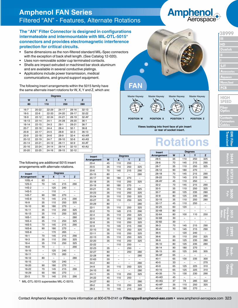
Contact Amphenol Aerospace for more information at 800-678-0141 or [email protected] • www.amphenol-aerospace.com 323
AmphenolAerospace
II Dualok
III
SJT
38999
I
PCB
Accessories
Aquacon
HD
EMI Filter
Transient
Herm/Seal
Fiber Optics
ContactsConnectorsCables
HIgH SPEED
26482M
atrix 2 83723 IIIM
atrix|Pyle5015
Crimp Rear
Release M
atrix
26500 Pyle
22992 C
lass L Back- Shells
Options
Others
• “D” shaped mounting hole dimensionsPlug movement required to clear FPT receptacles: .438 min.
Amphenol FAN SeriesFiltered “AN” - Features, Alternate Rotations
The following are additional 5015 insert arrangements with alternate rotations.
Insert Arrangement
DegreesW X Y Z
10SL-4 63 – – –
12S-3 70 145 215 290
14S-2 – 120 240 –
14S-5 – 110 – –
14S-7 90 180 270 –
14S-9 70 145 215 290
16-9 35 110 250 325
16-10 90 180 270 –
16-11 35 110 250 325
16-13 35 110 250 325
16S-1 80 – – 280
16S-4 35 110 250 325
16S-5 70 145 215 290
16S-6 90 180 270 –
16S-8 – 170 265 –
18-1 70 145 215 290
18-3 35 110 250 325
18-4 35 110 250 325
18-8 70 – – 290
18-10 – 120 240 –
18-11 – 170 265 –
18-12 80 – – 280
18-15 – 120 240 –
18-20 90 180 270 –
18-22 70 145 215 290
18-29 90 180 270 –
20-3 70 145 215 290
Insert Arrangement
DegreesW X Y Z
20-4 45 110 250 –
20-5 35 110 250 325
20-6 70 145 215 290
20-15 80 – – 280
20-17 90 180 270 –
20-18 35 110 250 325
20-19 90 180 270 –
20-21 35 110 250 325
20-23 35 110 250 325
20-24 35 110 250 325
20-27 35 110 250 325
20-29 80 – – 280
22-1 35 110 250 325
22-2 70 145 215 290
22-4 35 110 250 325
22-5 35 110 250 325
22-8 35 110 250 325
22-9 70 145 215 290
22-10 35 110 250 325
22-11 35 110 250 325
22-13 35 110 250 325
22-20 35 110 250 325
22-22 – 110 250 –
22-23 35 – 250 –
22-27 80 – 250 280
22-28 80 – – 280
22-63 20 – – –
24-2 80 – – 280
24-9 35 110 250 325
24-10 80 – – 280
24-11 35 110 250 325
24-22 45 110 250 –
24-27 80 – – 280
28-2 35 110 250 325
28-3 70 145 215 290
Insert Arrangement
DegreesW X Y Z
28-5 35 110 250 325
28-6 70 145 215 290
28-7 35 110 250 325
28-12 90 180 270 –
28-18 70 145 215 290
28-22 70 145 215 290
28-AY 45 110 250 –
32-2 70 145 215 290
32-5 35 110 250 325
32-7 80 125 235 280
32-8 80 125 235 280
32-15 35 110 250 280
32-17 45 110 250 –
32-25 60 120 – –
32-48 80 – – –
32-64 80 100 110 250
32-68 30 – – –
32-82 30 – – –
36-3 70 145 215 290
36-4 70 145 215 290
36-5 – 120 240 –
36-6 35 110 250 325
36-9 80 125 235 280
36-10 80 125 235 280
36-14 90 180 270 –
36-15 60 125 245 305
36-AF 65 – – –
40-1 65 130 235 300
40-5 33 – – 270
40-9 65 125 225 310
40-10 65 125 225 310
40-35 70 130 230 290
40-AD 45 – – –
40-AG 37 74 285 322
40-AP 35 110 250 325
40-AV 90 180 270 –
* MIL-DTL-5015 supersedes MIL-C-5015.
Rotations
FAN
AB
Master Keyway
POSITION W
Master Keyway
POSITION X
Master Keyway
POSITION Y
Master Keyway
POSITION Z
Views looking into front face of pin insert or rear of socket insert.
AB A
B
BA
The “AN” Filter Connector is designed in configurations intermate able and intermountable with MIL-DTL-5015* connectors and pro vides electromagnetic interference protection for critical circuits.• Same dimensions as the non-filtered standard MIL-Spec connectors
with the exception of back shell length. (See Catalog 12-020).• Uses non-removable solder cup terminated contacts.• Shells are impact extruded or machined bar stock aluminum
and are available in several conductive platings.• Applications include power transmission, medical
communications, and ground support equipment.
The following insert arrangements within the 5015 family have the same alternate insert rotations for W, X, Y and Z, which are:
Degrees
W X Y Z
80 110 250 280
16-7 20-22 22-29 24-17 28-16 32-13
18-5 22-6 22-33 24-20 28-17 32-22
18-9 22-12 22-34 24-21 28-19 32-AF
18-13 22-14 24-1 24-28 28-20 36-1
18-14 22-15 24-3 28-1 28-21 36-7
20-7 22-16 24-4 28-4 32-1 36-8
20-8 22-17 24-5 28-8 32-3 36-13
20-9 22-18 24-6 28-9 32-4 40-AR
20-12 22-19 24-7 28-10 32-6 40-AS
20-14 22-21 24-12 28-11 32-9 40-AT
20-16 22-24 24-14 28-14 32-10 40-AU
20-20 22-25 24-16 28-15 32-12
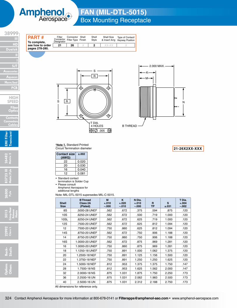
Contact Amphenol Aerospace for more information at 800-678-0141 or [email protected] • www.amphenol-aerospace.com324
AmphenolAerospace
Dualok
III
SJT
38999
PCB
HD
EMI F
ilter
Tran
sien
t
I II
Accessories
Herm/Seal
Aquacon
Fiber Optics
ContactsConnectors
Cables
HIgH SPEED
2648
2M
atrix
2
8372
3 III
5015
2650
0 Py
le
2299
2 C
lass
L
Back
- Sh
ells
Opt
ions
O
ther
sCr
imp
Rear
Rele
ase
Mat
rix
Mat
rix|P
yle
2.000 MAX.
K
M
N
B THREADT DIA.4 HOLES
.005 M
R
S
RS
*
FAN (MIL-DTL-5015)Box Mounting Receptacle
Shell Size
B ThreadClass 2A(Plated)
M+.010–.000
K+.020–.010
N Dia.+.010–.000
RTP
S±.031
T Dia.+.004–.002
8S .5000-28 UNEF .562 .672 .375 .594 .875 .120
10S .6250-24 UNEF .562 .672 .500 .719 1.000 .120
10SL .6250-24 UNEF .562 .672 .625 .719 1.000 .120
12S .7500-20 UNEF .562 .672 .625 .812 1.094 .120
12 .7500-20 UNEF .750 .860 .625 .812 1.094 .120
14S .8750-20 UNEF .562 .672 .750 .906 1.188 .120
14 .8750-20 UNEF .750 .860 .750 .906 1.188 .120
16S 1.0000-20 UNEF .562 .672 .875 .969 1.281 .120
16 1.0000-20 UNEF .750 .860 .875 .969 1.281 .120
18 1.1250-18 UNEF .750 .891 1.000 1.062 1.375 .120
20 1.2500-18 NEF .750 .891 1.125 1.156 1.500 .120
22 1.3750-18 NEF .750 .891 1.250 1.250 1.625 .120
24 1.5000-18 NEF .812 .953 1.375 1.375 1.750 .147
28 1.7500-18 NS .812 .953 1.625 1.562 2.000 .147
32 2.0000-18 NS .875 1.031 1.875 1.750 2.250 .173
36 2.2500-16 UN .875 1.031 2.062 1.983 2.500 .173
40 2.5000-16 UN .875 1.031 2.312 2.188 2.750 .173
All dimensions for reference only.
21-26X2XX-XXX
Note: MIL-DTL-5015 supersedes MIL-C-5015.
21 26 X 2 XX-XX X
Filter Connector Designator
Connector Filter Type
Shell Finish
Shell Style
Shell Size& Insert Arrg
Type of Contact/Keyway Position
To complete, see how to order pages 278-280.
PART #
Contact size (AWG)
±.002
22 0.02020 0.03016 0.04012 0.081
*Note 1. Standard Printed Circuit Termination diameter
• Standard contact termination is Solder Cup• Please consult Amphenol Aerospace for additional lengths
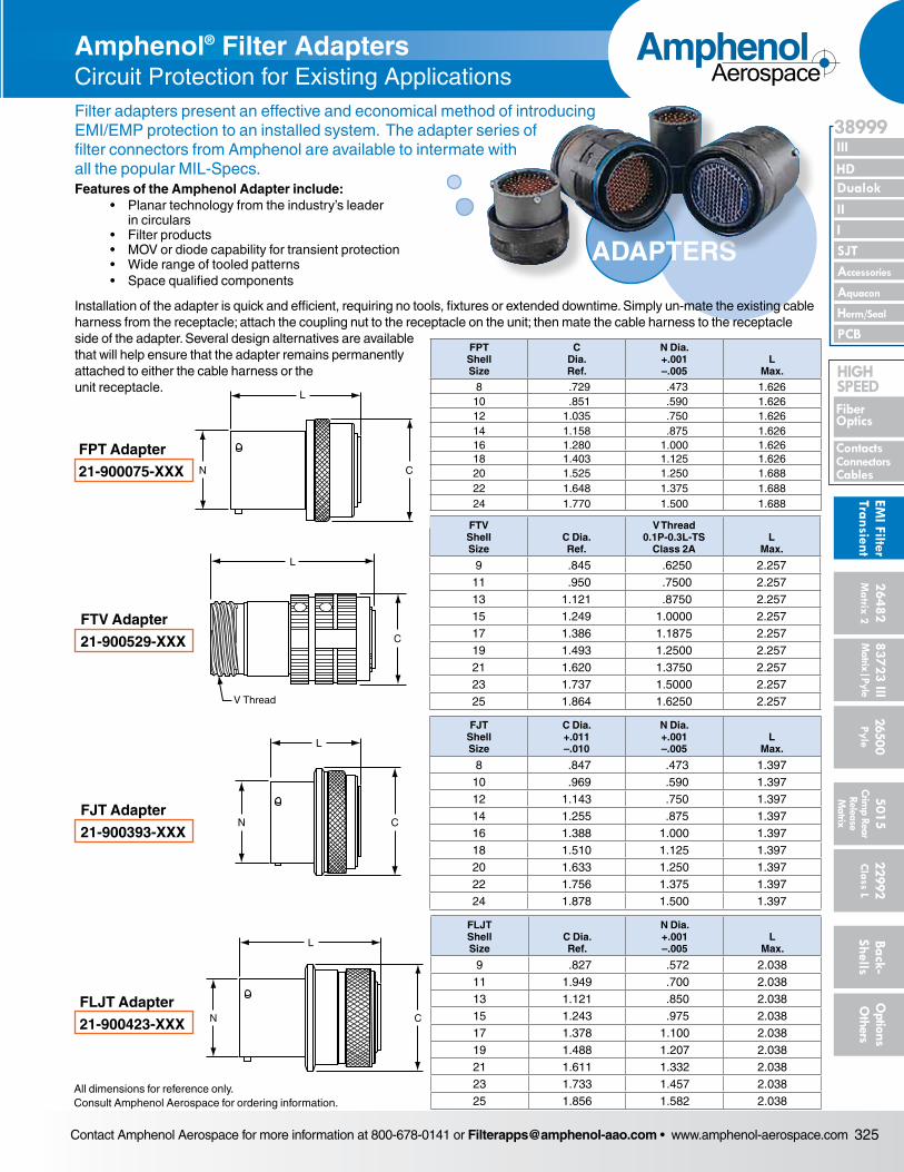
Contact Amphenol Aerospace for more information at 800-678-0141 or [email protected] • www.amphenol-aerospace.com 325
AmphenolAerospace
II Dualok
III
SJT
38999
I
PCB
Accessories
Aquacon
HD
EMI Filter
Transient
Herm/Seal
Fiber Optics
ContactsConnectorsCables
HIgH SPEED
26482M
atrix 2 83723 IIIM
atrix|Pyle5015
Crimp Rear
Release M
atrix
26500 Pyle
22992 C
lass L Back- Shells
Options
Others
FAN (MIL-DTL-5015)Box Mounting Receptacle
Amphenol® Filter Adapters Circuit Protection for Existing Applications
L
V Thread
C
FTV Adapter
21-900529-XXX
L
N CFJT Adapter
21-900393-XXX
FJT Shell Size
C Dia. +.011 –.010
N Dia. +.001 –.005
L Max.
8 .847 .473 1.39710 .969 .590 1.39712 1.143 .750 1.39714 1.255 .875 1.39716 1.388 1.000 1.39718 1.510 1.125 1.39720 1.633 1.250 1.39722 1.756 1.375 1.39724 1.878 1.500 1.397
L
N CFLJT Adapter
21-900423-XXX
FLJT Shell Size
C Dia. Ref.
N Dia. +.001 –.005
L Max.
9 .827 .572 2.03811 1.949 .700 2.03813 1.121 .850 2.03815 1.243 .975 2.03817 1.378 1.100 2.03819 1.488 1.207 2.03821 1.611 1.332 2.03823 1.733 1.457 2.03825 1.856 1.582 2.038
All dimensions for reference only.Consult Amphenol Aerospace for ordering information.
FTV Shell Size
C Dia. Ref.
V Thread 0.1P-0.3L-TS
Class 2AL
Max.
9 .845 .6250 2.25711 .950 .7500 2.25713 1.121 .8750 2.25715 1.249 1.0000 2.25717 1.386 1.1875 2.25719 1.493 1.2500 2.25721 1.620 1.3750 2.25723 1.737 1.5000 2.25725 1.864 1.6250 2.257
L
N C
FPT Adapter
21-900075-XXX
FPT Shell Size
C Dia. Ref.
N Dia. +.001 –.005
L Max.
8 .729 .473 1.62610 .851 .590 1.62612 1.035 .750 1.62614 1.158 .875 1.62616 1.280 1.000 1.62618 1.403 1.125 1.62620 1.525 1.250 1.68822 1.648 1.375 1.68824 1.770 1.500 1.688
ADAPTERS
Filter adapters present an effective and economical method of introducing EMI/EMP protection to an installed system. The adapter series of filter connectors from Amphenol are available to intermate with all the popular MIL-Specs.Features of the Amphenol Adapter include: • Planar technology from the industry’s leader in circulars • Filter products • MOV or diode capability for transient protection • Wide range of tooled patterns • Space qualified components
Installation of the adapter is quick and efficient, requiring no tools, fixtures or extended downtime. Simply un-mate the exist ing cable harness from the receptacle; attach the coupling nut to the receptacle on the unit; then mate the cable harness to the receptacle side of the adapter. Several design alternatives are available that will help ensure that the adapter remains permanently attached to either the cable harness or the unit receptacle.
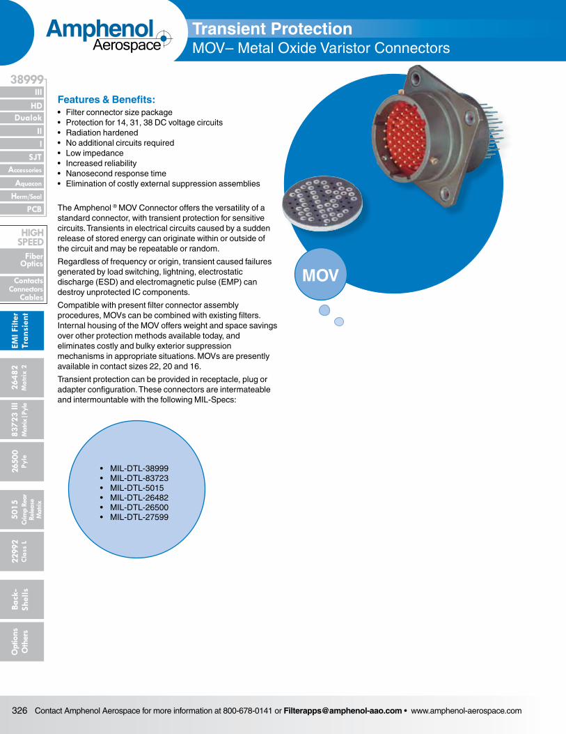
Contact Amphenol Aerospace for more information at 800-678-0141 or [email protected] • www.amphenol-aerospace.com326
AmphenolAerospace
Dualok
III
SJT
38999
PCB
HD
EMI F
ilter
Tran
sien
t
I II
Accessories
Herm/Seal
Aquacon
Fiber Optics
ContactsConnectors
Cables
HIgH SPEED
2648
2M
atrix
2
8372
3 III
5015
2650
0 Py
le
2299
2 C
lass
L
Back
- Sh
ells
Opt
ions
O
ther
sCr
imp
Rear
Rele
ase
Mat
rix
Mat
rix|P
yle
Features & Benefits: • Filter connector size package• Protection for 14, 31, 38 DC voltage circuits• Radiation hardened• No additional circuits required• Low impedance• Increased reliability• Nanosecond response time• Elimination of costly external suppression assemblies
The Amphenol ® MOV Connector offers the versatility of a stan dard connector, with transient protection for sensitive circuits. Transients in electrical circuits caused by a sudden release of stored energy can originate within or outside of the circuit and may be repeatable or random.
Regardless of frequency or origin, transient caused failures generated by load switching, lightning, electrostatic discharge (ESD) and electromagnetic pulse (EMP) can destroy unpro tected IC components.
Compatible with present filter connector assembly procedures, MOVs can be combined with existing filters. Internal housing of the MOV offers weight and space savings over other pro tection methods available today, and eliminates costly and bulky exterior suppression mechanisms in appropriate situations. MOVs are presently available in contact sizes 22, 20 and 16.
Transient protection can be provided in receptacle, plug or adapter configuration. These connectors are intermateable and intermountable with the following MIL-Specs:
Transient ProtectionMOV– Metal Oxide Varistor Connectors
MOV
• MIL-DTL-38999• MIL-DTL-83723 • MIL-DTL-5015• MIL-DTL-26482• MIL-DTL-26500• MIL-DTL-27599
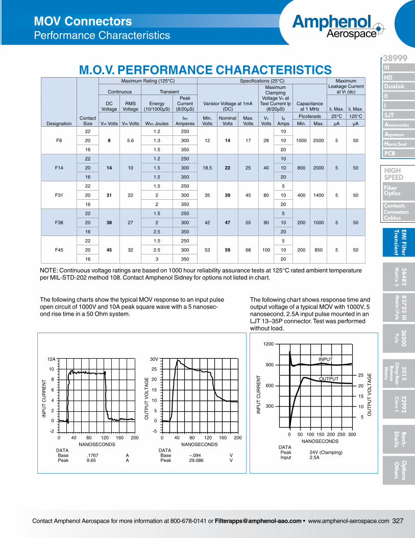
Contact Amphenol Aerospace for more information at 800-678-0141 or [email protected] • www.amphenol-aerospace.com 327
AmphenolAerospace
II Dualok
III
SJT
38999
I
PCB
Accessories
Aquacon
HD
EMI Filter
Transient
Herm/Seal
Fiber Optics
ContactsConnectorsCables
HIgH SPEED
26482M
atrix 2 83723 IIIM
atrix|Pyle5015
Crimp Rear
Release M
atrix
26500 Pyle
22992 C
lass L Back- Shells
Options
Others
0 40 80 120 160 200 0 40 80 120 160 200-2
0
2
4
6
8
12A
10
NANOSECONDS
INP
UT
CU
RR
EN
T
DATABase .1767 APeak 9.65 A
-5
0
5
10
15
20
30V
25
NANOSECONDS
OU
TP
UT
VO
LTA
GE
DATABase –.094 VPeak 29.086 V
NANOSECONDS
INP
UT
CU
RR
EN
T
DATAPeak 24V (Clamping)Input 2.5A
300
600
900
1200
25
20
15
10
5
0 50 100 150 200 250 300
OU
TP
UT
VO
LTA
GE
OUTPUT
INPUT
MOV ConnectorsPerformance Characteristics
The following charts show the typical MOV response to an input pulse open circuit of 1000V and 10A peak square wave with a 5 nanosec-ond rise time in a 50 Ohm system.
The following chart shows response time and output voltage of a typical MOV with 1000V, 5 nanosecond, 2.5A input pulse mounted in an LJT 13–35P connector. Test was performed without load.
NOTE: Continuous voltage ratings are based on 1000 hour reliability assurance tests at 125°C rated ambient temperature per MIL-STD-202 method 108. Contact Amphenol Sidney for options not listed in chart.
M.O.V. PERFORMANCE CHARACTERISTICS
DesignationContact
Size
Maximum Rating (125°C) Specifications (25°C) Maximum Leakage Current
at Vt (dc)Continuous Transient
Varistor Voltage at 1mA (DC)
Maximum Clamping
Voltage Vc at Test Current lp
(8/20µS)Capacitance
at 1 MHzDC
VoltageRMS
VoltageEnergy
(10/1000µS)
Peak Current (8/20µS) IL Max. IL Max.
Vm Volts Vm Volts Wtm JoulesItm
AmperesMin. Volts
Nominal Volts
Max. Volts
Vc Volts
Ip Amps
Picofarads 25°C 125°C
Min. Max. µA µA
F8
22
8 5.6
1.2 250
12 14 17 28
10
1000 2500 5 5020 1.3 300 10
16 1.5 350 20
F14
22
14 10
1.2 250
18.5 22 25 40
10
800 2000 5 5020 1.5 300 10
16 1.5 350 20
F31
22
31 22
1.5 250
35 39 45 80
5
400 1400 5 5020 2 300 10
16 2 350 20
F38
22
38 27
1.5 250
42 47 55 90
5
200 1000 5 5020 2 300 10
16 2.5 350 20
F45
22
45 32
1.5 250
53 59 68 100
5
200 850 5 5020 2.5 300 10
16 3 350 20
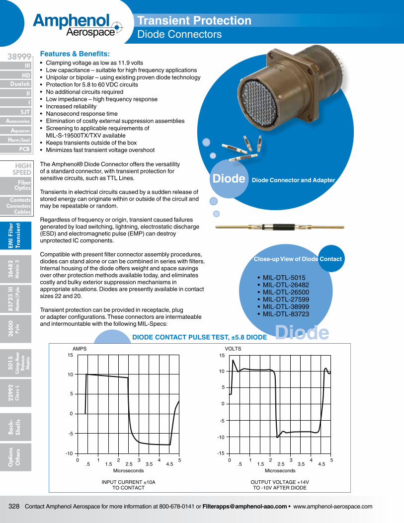
Contact Amphenol Aerospace for more information at 800-678-0141 or [email protected] • www.amphenol-aerospace.com328
AmphenolAerospace
Dualok
III
SJT
38999
PCB
HD
EMI F
ilter
Tran
sien
t
I II
Accessories
Herm/Seal
Aquacon
Fiber Optics
ContactsConnectors
Cables
HIgH SPEED
2648
2M
atrix
2
8372
3 III
5015
2650
0 Py
le
2299
2 C
lass
L
Back
- Sh
ells
Opt
ions
O
ther
sCr
imp
Rear
Rele
ase
Mat
rix
Mat
rix|P
yle
Diode
Diode
Features & Benefits: • Clamping voltage as low as 11.9 volts• Low capacitance – suitable for high frequency applications• Unipolar or bipolar – using existing proven diode technology• Protection for 5.8 to 60 VDC circuits• No additional circuits required• Low impedance – high frequency response• Increased reliability• Nanosecond response time• Elimination of costly external suppression assemblies• Screening to applicable requirements of
MIL-S-19500TX/TXV available• Keeps transients outside of the box• Minimizes fast transient voltage overshoot
The Amphenol® Diode Connector offers the versatility of a standard connector, with transient protection for sensitive cir cuits, such as TTL Lines.
Transients in electrical circuits caused by a sudden release of stored energy can originate within or outside of the circuit and may be repeatable or random.
Regardless of frequency or origin, transient caused failures generated by load switching, lightning, electrostatic discharge (ESD) and electromagnetic pulse (EMP) can destroy unpro tected IC components.
Compatible with present filter connector assembly procedures, diodes can stand alone or can be combined in series with fil ters. Internal housing of the diode offers weight and space sav ings over other protection methods available today, and eliminates costly and bulky exterior suppression mechanisms in appropriate situations. Diodes are presently available in contact sizes 22 and 20.
Transient protection can be provided in receptacle, plug or adapter configurations. These connectors are intermateable and intermountable with the following MIL-Specs:
Diode Connector and Adapter
Transient Protection Diode Connectors
AMPS
-10
-5
0
5
10
15
0 1 2 3 4 5.5 1.5 2.5 3.5 4.5
-10
-5
0
5
10
15
0 1 2 3 4 5.5 1.5 2.5 3.5 4.5
-15
VOLTS
INPUT CURRENT ±10ATO CONTACT
OUTPUT VOLTAGE +14VTO -10V AFTER DIODE
MicrosecondsMicroseconds
DIODE CONTACT PULSE TEST, ±5.8 DIODE
• MIL-DTL-5015 • MIL-DTL-26482 • MIL-DTL-26500 • MIL-DTL-27599 • MIL-DTL-38999 • MIL-DTL-83723
Close-up View of Diode Contact
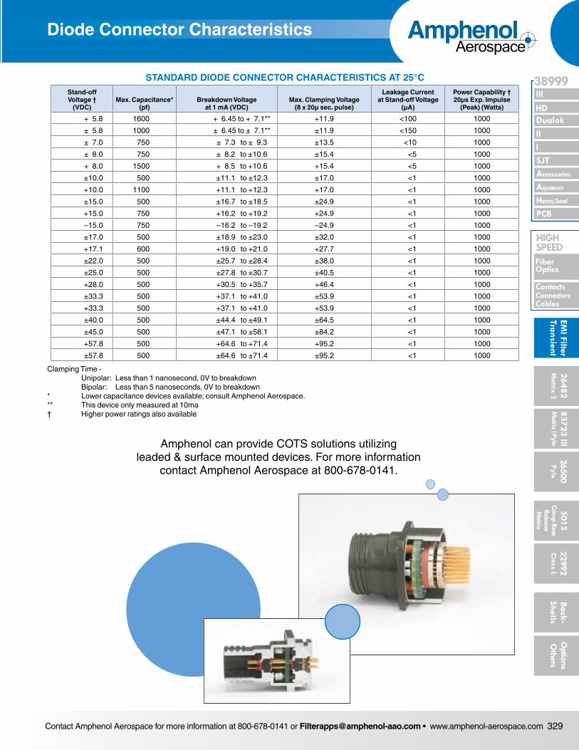
Contact Amphenol Aerospace for more information at 800-678-0141 or [email protected] • www.amphenol-aerospace.com 329
AmphenolAerospace
II Dualok
III
SJT
38999
I
PCB
Accessories
Aquacon
HD
EMI Filter
Transient
Herm/Seal
Fiber Optics
ContactsConnectorsCables
HIgH SPEED
26482M
atrix 2 83723 IIIM
atrix|Pyle5015
Crimp Rear
Release M
atrix
26500 Pyle
22992 C
lass L Back- Shells
Options
Others
Transient Protection Diode Connectors
STANDARD DIODE CONNECTOR CHARACTERISTICS AT 25°CStand-off Voltage †
(VDC)Max. Capacitance*
(pf)Breakdown Voltage
at 1 mA (VDC)Max. Clamping Voltage
(8 x 20µ sec. pulse)
Leakage Current at Stand-off Voltage
(µA)
Power Capability † 20µs Exp. Impulse
(Peak) (Watts)
+ 5.8 1600 + 6.45 to + 7.1** +11.9 <100 1000
± 5.8 1000 ± 6.45 to ± 7.1** ±11.9 <150 1000
± 7.0 750 ± 7.3 to ± 9.3 ±13.5 <10 1000
± 8.0 750 ± 8.2 to ±10.6 ±15.4 <5 1000
+ 8.0 1500 + 8.5 to +10.6 +15.4 <5 1000
±10.0 500 ±11.1 to ±12.3 ±17.0 <1 1000
+10.0 1100 +11.1 to +12.3 +17.0 <1 1000
±15.0 500 ±16.7 to ±18.5 ±24.9 <1 1000
+15.0 750 +16.2 to +19.2 +24.9 <1 1000
–15.0 750 –16.2 to –19.2 –24.9 <1 1000
±17.0 500 ±18.9 to ±23.0 ±32.0 <1 1000
+17.1 600 +19.0 to +21.0 +27.7 <1 1000
±22.0 500 ±25.7 to ±28.4 ±38.0 <1 1000
±25.0 500 ±27.8 to ±30.7 ±40.5 <1 1000
+28.0 500 +30.5 to +35.7 +46.4 <1 1000
±33.3 500 +37.1 to +41.0 ±53.9 <1 1000
+33.3 500 +37.1 to +41.0 +53.9 <1 1000
±40.0 500 ±44.4 to ±49.1 ±64.5 <1 1000
±45.0 500 ±47.1 to ±58.1 ±84.2 <1 1000
+57.8 500 +64.6 to +71.4 +95.2 <1 1000
±57.8 500 ±64.6 to ±71.4 ±95.2 <1 1000
Clamping Time - Unipolar: Less than 1 nanosecond, 0V to breakdown Bipolar: Less than 5 nanoseconds, 0V to breakdown* Lower capacitance devices available; consult Amphenol Aerospace.** This device only measured at 10ma† Higher power ratings also available
Diode Connector Characteristics
Amphenol can provide COTS solutions utilizing leaded & surface mounted devices. For more information
contact Amphenol Aerospace at 800-678-0141.
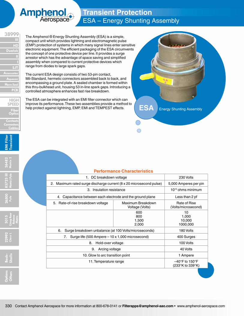
Contact Amphenol Aerospace for more information at 800-678-0141 or [email protected] • www.amphenol-aerospace.com330
AmphenolAerospace
Dualok
III
SJT
38999
PCB
HD
EMI F
ilter
Tran
sien
t
I II
Accessories
Herm/Seal
Aquacon
Fiber Optics
ContactsConnectors
Cables
HIgH SPEED
2648
2M
atrix
2
8372
3 III
5015
2650
0 Py
le
2299
2 C
lass
L
Back
- Sh
ells
Opt
ions
O
ther
sCr
imp
Rear
Rele
ase
Mat
rix
Mat
rix|P
yle
The Amphenol ® Energy Shunting Assembly (ESA) is a simple, compact unit which provides lightning and electromagnetic pulse (EMP) protection of systems in which many signal lines enter sensitive electronic equipment. The efficient packaging of the ESA circumvents the concept of one protective device per line. It provides a surge arrestor which has the advantage of space sav ing and simplified assembly when compared to current protective devices which range from diodes to large spark gaps.
The current ESA design consists of two 53-pin contact, Mil-Stan dard, hermetic connectors assembled back to back, and encom passing a ground plate. A sealed chamber is formed within this thru-bulkhead unit, housing 53 in-line spark gaps. Introducing a controlled atmosphere enhances fast rise breakdown.
The ESA can be integrated with an EMI filter connector which can improve its performance. These two assemblies provide a method to help protect against lightning, EMP, EMI and TEM PEST effects.
Transient ProtectionESA – Energy Shunting Assembly
Diode
ESA Energy Shunting Assembly
1. DC breakdown voltage 230 Volts
2. Maximum rated surge discharge current (8 x 20 microsecond pulse) 5,000 Amperes per pin
3. Insulation resistance 1010 ohms minimum
4. Capacitance between each electrode and the ground plane Less than 2 pf
5. Rate-of-rise breakdown voltage Maximum BreakdownVoltage (Volts)
Rate of Rise(Volts/microsecond)
600 800
1,500 2,000
10 1,000
10,000 1000,000
6. Surge breakdown unbalance (at 100 Volts/microseconds) 180 Volts
7. Surge life (500 Ampere – 10 x 1,000 microsecond) 400 Surges
8. Hold-over voltage 100 Volts
9. Arcing voltage 40 Volts
10. Glow to arc transition point 1 Ampere
11. Temperature range –40°F to 150°F (233°K to 339°K)
Performance Characteristics
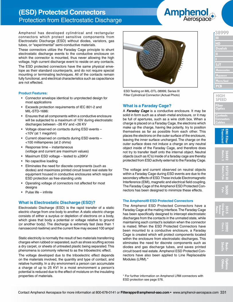
Contact Amphenol Aerospace for more information at 800-678-0141 or [email protected] • www.amphenol-aerospace.com 331
AmphenolAerospace
II Dualok
III
SJT
38999
I
PCB
Accessories
Aquacon
HD
EMI Filter
Transient
Herm/Seal
Fiber Optics
ContactsConnectorsCables
HIgH SPEED
26482M
atrix 2 83723 IIIM
atrix|Pyle5015
Crimp Rear
Release M
atrix
26500 Pyle
22992 C
lass L Back- Shells
Options
Others
Amphenol has developed cylindr ical and rectangular connectors which protect sensitive components from Electrostatic Discharge (ESD) without diodes, varistors, gas tubes, or “experimental” semi-conductive materials.These connectors utilize the Faraday Cage principle to shunt electro static discharge events to the conductive enclosure on which the con nector is mounted, thus never allowing the high voltage, high current discharge event to reside on any contacts.The ESD protected connectors have the same physical enve-lope as their standard counterparts, and do not require special mounting or ter minating techniques. All of the contacts remain fully functional, and electrical characteristics such as capacitance are not effected.
Product Features: • Connector envelope identical to unprotected design for most applications • Exceeds protection requirements of IEC 801-2 and MIL-STD-1686: • Ensures that all components within a conductive enclosure will be sub jected to a maximum of 10V during electrostatic discharges between –26 KV and +26 KV • Voltage observed on contacts during ESD events – <10V (at 1 megohm) • Current observed on contacts during ESD events – <100 milliamperes (at 2 ohms) • Response time – instantaneous (voltage and current are maximum values) • Maximum ESD voltage – tested to ±26KV • No capacitive loading • Eliminates the need for discrete components (such as diodes) and max imizes printed circuit board real estate for equipment housed in con ductive enclosures which require ESD protection as free-standing units • Operating voltage of connectors not affected for most designs • Pulse life – infinite
What is Electrostatic Discharge (ESD)?Electrostatic Discharge (ESD) is the rapid transfer of a static electric charge from one body to another. A static electric charge consists of either a surplus or depletion of electrons on a body, which gives that body a potential or voltage relative to ground (or another body). The discharge is extremely fast (less than 1 nanosecond risetime) and the current flow may exceed 100 amps!
Static electricity is normally the result of two materials transferring charges when rubbed or separated, such as shoes scuffing across a dry carpet, or sheets of untreated plastic being separated. This phe nomena is commonly referred to as the triboelectric effect.The voltage developed due to the triboelectric effect depends on the materials involved, the quantity and type of contact, and relative humid ity. In a dry environment a person can accumulate a charge of up to 25 KV! In a moist environment a person’s potential is reduced due to the effect of moisture on the insulating properties of materials.
What is a Faraday Cage?A Faraday Cage is a conductive enclosure. It may be solid in form such as a sheet–metal enclosure, or it may be full of apertures, such as a wire cloth box. When a charge is placed on a Faraday Cage, the electrons which make up the charge, having like polarity, try to position themselves as far as possible from each other. This places the electrons on the outer surface of the enclo sure, leaving the inner surface uncharged. The charge on the outer surface does not induce a charge on any neutral object inside of the Faraday Cage, and therefore does not try to transfer itself onto the internal object. Neutral objects (such as IC’s) inside of a faraday cage are thereby protected from ESD activity external to the Fara day Cage.
The voltage and current observed on neutral objects within a Faraday Cage during ESD events are due to the secondary effects of ESD. These include Electromagnetic Interference (EMI), magnetic and electrical field coupling. The Faraday Cage of the Amphenol ESD Protected Con-nectors has been designed to minimize these effects.
The Amphenol® ESD Protected ConnectorsThe Amphenol ESD Protected Connectors have a Fara day Cage at the mating interface. The Faraday Cage has been specifically designed to intercept electrostatic dis charges from the contacts in the unmated state, while maintaining each contact’s isolation when the connector is mated. When the ESD Protected Connectors have been mounted to a conductive enclosure, a Faraday Cage is created which will protect components located within the enclosure from electrostatic discharges. This elimi nates the need for discrete components such as diodes and gas discharge tubes, and saves printed circuit board real estate. Amphenol ESD Protected Con-nectors have also been applied to Line Replaceable Modules (LRM).*
ESD Testing on MIL-DTL-38999, Series III Filter Cylindrical Connector (Actual Photo)
* For further information on Amphenol LRM connectors with ESD protection see page 576.
(ESD) Protected ConnectorsProtection from Electrostatic Discharge