Embed Size (px)
Citation preview
An Autonomous Self-Replicating Robotic System
Jackrit Suthakorn Andrew B. Cushing Gregory S. Chirikjian* [email protected] [email protected] [email protected]
Robot and Protein Kinematics Laboratory Department of Mechanical Engineering, The Johns Hopkins University
Baltimore, Maryland 21218 USA
Abstract The concept of self-replicating machines was introduced more than fifty years ago by John von Neumann. However, to our knowledge a fully autonomous self-replicating robot has not been implemented until now. Here we describe a fully autonomous prototype that demonstrates robotic self replication. This work builds on our previous results in remote-controlled robotic replication and semi-autonomous replicating robotic systems.
Keyword Self-Replication, Artificial Life, Robot, Modular Robots INTERODUCTION In this paper, we develop a physical prototype capable of fully autonomous self replication in a laboratory setting. This work builds upon our previous results in remote-controlled robotic replication presented in [1], and a semi-autonomous replicating robotic system presented in [2]. The new prototype uses two light sensors in its navigation system to detect objects and to also track lines. Our prototype is constructed from modified LEGO Mindstorm kits in which the electrical connections are enhanced. Magnets and shape-constraining blocks are employed to aid in the aligning and interlocking of the replica’s subsystems. We also discuss the motivation for studying self-replicating systems and review previous works. Finally, results of experiments with our prototype system are discussed.
Motivation People have imagined for years a factory that could
autonomously replicate itself for multiple generations, requiring neither people nor the monstrous machinery typically associated with a factory. Over the recent decades, outer space has been mentioned as one potential application for such self-replicating robotic factories (see e.g., [3-5]). However, enormous technical barriers must be overcome before these systems can become feasible. The purpose of the current work is to take one small step toward realizing this goal.
In contrast to self-reconfigurable robotics [6-10], self-replication utilizes an original unit to actively assemble an exact copy of itself from passive components. This can result in exponential growth in the number of robots available to perform a job, thus drastically shortening the original unit’s task time.
Previous Efforts in Mechanical Self-Replicating System
Von Neumann [11] was the first to seriously study the idea of self-replicating machines from a theoretical perspective. Von Neumann introduced the theory of automata and established a quantitative definition of self-replication. His early results on self-replicating machines have become useful in several diverse research areas such as: cellular automata, nanotechnology, macromolecular chemistry, and computer programming (more details in [12].)
In the late 1950’s, Penrose performed the first recognized demonstration of a self-replicating mechanical system [13]. It consisted of passive elements that self-assembled only under external agitation. This is similar in many ways to the modern work of Whitesides [14], only at a different length scale.
More than 20 years after Penrose, NASA established a series of studies on the topic of “Advanced Automation for Space Missions” [3]. These studies investigated the possibility of building a self-replicating factory on the moon. References [15-19] also outlined strategies for space utilization. Recently, research on robots that are capable of designing other machines with little help from humans has also been performed (see [20] and references therein). This relies on the use of rapid prototyping technologies.
DESIGN AND DESCRIPTIONS OF AN AUTONOMOUS SELF-REPLICATING ROBOT The robot and its replicas each consist of four subsystems: controller, left tread, right tread, and gripper/sensor subsystems. All subsystems are connected to others using magnets and shape constraints. Figure 1 shows an assembly view of the robot.
The controller subsystem is made up of a LEGO RCX programmable controller fit inside a chassis. The chassis's sides are used to connect to the left and right treads. Each side has a set of magnets, a set of shape-constraining blocks, and a set of electrical connections. The front end of the chassis is designed to attach with the gripper. The front end also has a set of magnets, a set of shape-constraining blocks, and a set of electrical connections, which transfer electrical and electronic signals from the controller to the gripper's motor and the navigating sensors installed on the gripper subsystem.
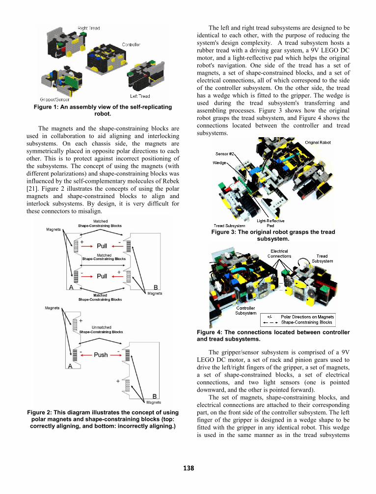
Figure 1: An assembly view of the self-replicating
robot.
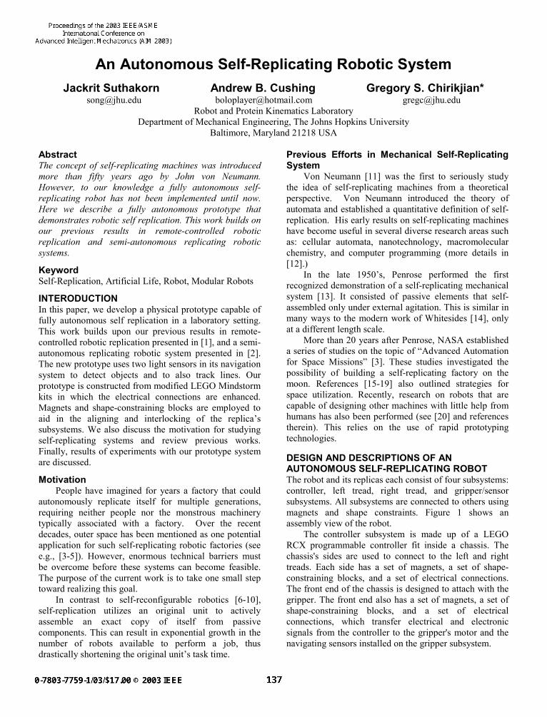
The magnets and the shape-constraining blocks are used in collaboration to aid aligning and interlocking subsystems. On each chassis side, the magnets are symmetrically placed in opposite polar directions to each other. This is to protect against incorrect positioning of the subsystems. The concept of using the magnets (with different polarizations) and shape-constraining blocks was influenced by the self-complementary molecules of Rebek [21]. Figure 2 illustrates the concepts of using the polar magnets and shape-constrained blocks to align and interlock subsystems. By design, it is very difficult for these connectors to misalign.
Figure 2: This diagram illustrates the concept of using
polar magnets and shape-constraining blocks (top: correctly aligning, and bottom: incorrectly aligning.)
The left and right tread subsystems are designed to be identical to each other, with the purpose of reducing the system's design complexity. A tread subsystem hosts a rubber tread with a driving gear system, a 9V LEGO DC motor, and a light-reflective pad which helps the original robot's navigation. One side of the tread has a set of magnets, a set of shape-constrained blocks, and a set of electrical connections, all of which correspond to the side of the controller subsystem. On the other side, the tread has a wedge which is fitted to the gripper. The wedge is used during the tread subsystem's transferring and assembling processes. Figure 3 shows how the original robot grasps the tread subsystem, and Figure 4 shows the connections located between the controller and tread subsystems.
Figure 3: The original robot grasps the tread
subsystem.
Figure 4: The connections located between controller and tread subsystems.
The gripper/sensor subsystem is comprised of a 9V LEGO DC motor, a set of rack and pinion gears used to drive the left/right fingers of the gripper, a set of magnets, a set of shape-constrained blocks, a set of electrical connections, and two light sensors (one is pointed downward, and the other is pointed forward).
The set of magnets, shape-constraining blocks, and electrical connections are attached to their corresponding part, on the front side of the controller subsystem. The left finger of the gripper is designed in a wedge shape to be fitted with the gripper in any identical robot. This wedge is used in the same manner as in the tread subsystems
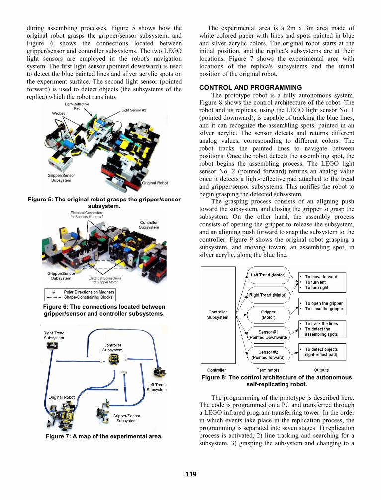
during assembling processes. Figure 5 shows how the original robot grasps the gripper/sensor subsystem, and Figure 6 shows the connections located between gripper/sensor and controller subsystems. The two LEGO light sensors are employed in the robot's navigation system. The first light sensor (pointed downward) is used to detect the blue painted lines and silver acrylic spots on the experiment surface. The second light sensor (pointed forward) is used to detect objects (the subsystems of the replica) which the robot runs into.
Figure 5: The original robot grasps the gripper/sensor
subsystem.
Figure 6: The connections located between gripper/sensor and controller subsystems.
Figure 7: A map of the experimental area.
The experimental area is a 2m x 3m area made of white colored paper with lines and spots painted in blue and silver acrylic colors. The original robot starts at the initial position, and the replica's subsystems are at their locations. Figure 7 shows the experimental area with locations of the replica's subsystems and the initial position of the original robot.
CONTROL AND PROGRAMMING
The prototype robot is a fully autonomous system. Figure 8 shows the control architecture of the robot. The robot and its replicas, using the LEGO light sensor No. 1 (pointed downward), is capable of tracking the blue lines, and it can recognize the assembling spots, painted in an silver acrylic. The sensor detects and returns different analog values, corresponding to different colors. The robot tracks the painted lines to navigate between positions. Once the robot detects the assembling spot, the robot begins the assembling process. The LEGO light sensor No. 2 (pointed forward) returns an analog value once it detects a light-reflective pad attached to the tread and gripper/sensor subsystems. This notifies the robot to begin grasping the detected subsystem.
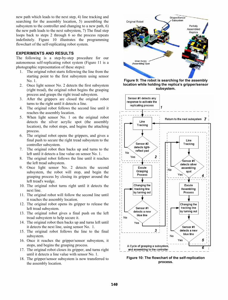
The grasping process consists of an aligning push toward the subsystem, and closing the gripper to grasp the subsystem. On the other hand, the assembly process consists of opening the gripper to release the subsystem, and an aligning push forward to snap the subsystem to the controller. Figure 9 shows the original robot grasping a subsystem, and moving toward an assembling spot, in silver acrylic, along the blue line.
Figure 8: The control architecture of the autonomous
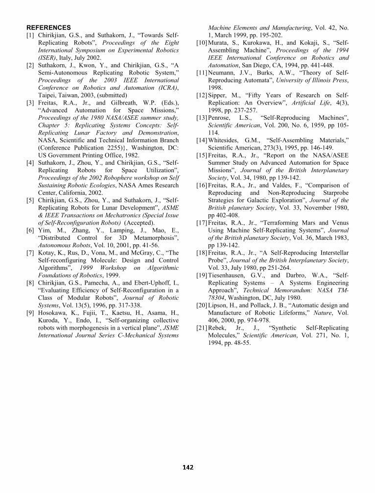
self-replicating robot. The programming of the prototype is described here.
The code is programmed on a PC and transferred through a LEGO infrared program-transferring tower. In the order in which events take place in the replication process, the programming is separated into seven stages: 1) replication process is activated, 2) line tracking and searching for a subsystem, 3) grasping the subsystem and changing to a
new path which leads to the next step, 4) line tracking and searching for the assembly location, 5) assembling the subsystem to the controller and changing to a new path, 6) the new path leads to the next subsystem, 7) The final step loops back to steps 2 through 6 so the process repeats indefinitely. Figure 10 illustrates the programming flowchart of the self-replicating robot system. EXPERIMENTS AND RESULTS The following is a step-by-step procedure for our autonomous self-replicating robot system (Figure 11 is a photographic representation of these steps):
1. The original robot starts following the line from the starting point to the first subsystem using sensor No. 1.
2. Once light sensor No. 2 detects the first subsystem (right tread), the original robot begins the grasping process and grasps the right tread subsystem.
3. After the grippers are closed the original robot turns to the right until it detects a line.
4. The original robot follows the second line until it reaches the assembly location.
5. When light sensor No. 1 on the original robot detects the silver acrylic spot (the assembly location), the robot stops, and begins the attaching process.
6. The original robot opens the grippers, and gives a final push to secure the right tread subsystem to the controller subsystem.
7. The original robot then backs up and turns to the left until it detects a line value on sensor No. 1.
8. The original robot follows the line until it reaches the left tread subsystem.
9. Once light sensor No. 2 detects the second subsystem, the robot will stop, and begin the grasping process by closing its gripper around the left tread's wedge.
10. The original robot turns right until it detects the next line.
11. The original robot will follow the second line until it reaches the assembly location.
12. The original robot opens its gripper to release the left tread subsystem.
13. The original robot gives a final push on the left tread subsystem to help secure it.
14. The original robot then backs up and turns left until it detects the next line, using sensor No. 1.
15. The original robot follows the line to the final subsystem.
16. Once it reaches the gripper/sensor subsystem, it stops, and begins the grasping process.
17. The original robot closes its gripper, and turns right until it detects a line value with sensor No. 1.
18. The gripper/sensor subsystem is now transferred to the assembly location.
Figure 9: The robot is searching for the assembly location while holding the replica’s gripper/sensor
subsystem.
Figure 10: The flowchart of the self-replication process.

19. Once the original robot reaches the assembly location it stops, and opens the gripper.
20. The original robot backs up and turns left until sensor No. 1 is a line value.
21. The original robot then follows the line back to the starting point, and is ready to replicate again.
22. The completed replica self-activates (20 seconds after completion) and begins following the line to the starting point.
23. Once each robot reaches the starting point, it begins the replication procedure again.
The replication process takes two minutes and fifteen seconds per cycle. Although each subsystem is required to be placed in its starting location, errors in initial position and orientation are not very critical. We found slight errors during the grasping process in a few experiments caused by improper placement of the subsystems. Overall, the system is robust and very repeatable.
CONCLUSION An autonomous self-replicating robot prototype has been constructed and tested. It uses two light sensors in its navigation system to detect objects and also to track lines. Magnets and shape-constraining blocks are used to aid in aligning and interlocking the subsystems of the replica. As a result, the robot is capable of automatically assembling its replicas. All the replicas are also capable of completing the same replicating process. We believe that this prototype is the world's first fully functional autonomous self-replicating robot. ACKNOWLEDGEMENTS This work was made possible by support from the Royal Thai government, the Mellon Foundation, and the National Science Foundation. The results and opinions expressed are solely those of the authors.
Figure 11: Self-replication process: 1) the original robot begins at the initial position with every part placed in their position. 2) The robot detects the right-tread subsystem. 3) The robot grasps the right-tread subsystem, and attaches it to the controller. 4) In the same manner, the robot performs the assembly of the left-tread subsystem. 5) After the robot grasps the gripper/sensor subsystem the robot transfers the subsystem to the next assembly step at the controller. 6) After being fully assembled, the replica is self-activated, and ready to replicate just like the original.
REFERENCES [1] Chirikjian, G.S., and Suthakorn, J., “Towards Self-
Replicating Robots”, Proceedings of the Eight International Symposium on Experimental Robotics (ISER), Italy, July 2002.
[2] Suthakorn, J., Kwon, Y., and Chirikjian, G.S., “A Semi-Autonomous Replicating Robotic System,” Proceedings of the 2003 IEEE International Conference on Robotics and Automation (ICRA), Taipei, Taiwan, 2003, (submitted)
[3] Freitas, R.A., Jr., and Gilbreath, W.P. (Eds.), “Advanced Automation for Space Missions,” Proceedings of the 1980 NASA/ASEE summer study, Chapter 5: Replicating Systems Concepts: Self-Replicating Lunar Factory and Demonstration, NASA, Scientific and Technical Information Branch (Conference Publication 2255)}, Washington, DC: US Government Printing Office, 1982.
[4] Suthakorn, J., Zhou, Y., and Chirikjian, G.S., “Self-Replicating Robots for Space Utilization”, Proceedings of the 2002 Robophere workshop on Self Sustaining Robotic Ecologies, NASA Ames Research Center, California, 2002.
[5] Chirikjian, G.S., Zhou, Y., and Suthakorn, J., “Self-Replicating Robots for Lunar Development”, ASME & IEEE Transactions on Mechatronics (Special Issue of Self-Reconfiguration Robots) (Accepted).
[6] Yim, M., Zhang, Y., Lamping, J., Mao, E., “Distributed Control for 3D Metamorphosis”, Autonomous Robots, Vol. 10, 2001, pp. 41-56.
[7] Kotay, K., Rus, D., Vona, M., and McGray, C., “The Self-reconfiguring Molecule: Design and Control Algorithms”, 1999 Workshop on Algorithmic Foundations of Robotics, 1999.
[8] Chirikjian, G.S., Pamecha, A., and Ebert-Uphoff, I., “Evaluating Efficiency of Self-Reconfiguration in a Class of Modular Robots”, Journal of Robotic Systems, Vol. 13(5), 1996, pp. 317-338.
[9] Hosokawa, K., Fujii, T., Kaetsu, H., Asama, H., Kuroda, Y., Endo, I., “Self-organizing collective robots with morphogenesis in a vertical plane”, JSME International Journal Series C-Mechanical Systems
Machine Elements and Manufacturing, Vol. 42, No. 1, March 1999, pp. 195-202.
[10] Murata, S., Kurokawa, H., and Kokaji, S., “Self-Assembling Machine”, Proceedings of the 1994 IEEE International Conference on Robotics and Automation, San Diego, CA, 1994, pp. 441-448.
[11] Neumann, J.V., Burks, A.W., “Theory of Self-Reproducing Automata”, University of Illinois Press, 1998.
[12] Sipper, M., “Fifty Years of Research on Self-Replication: An Overview”, Artificial Life, 4(3), 1998, pp. 237-257.
[13] Penrose, L.S., “Self-Reproducing Machines”, Scientific American, Vol. 200, No. 6, 1959, pp 105-114.
[14] Whitesides, G.M., “Self-Assembling Materials,” Scientific American, 273(3), 1995, pp. 146-149.
[15] Freitas, R.A., Jr., “Report on the NASA/ASEE Summer Study on Advanced Automation for Space Missions”, Journal of the British Interplanetary Society, Vol. 34, 1980, pp 139-142.
[16] Freitas, R.A., Jr., and Valdes, F., “Comparison of Reproducing and Non-Reproducing Starprobe Strategies for Galactic Exploration”, Journal of the British planetary Society, Vol. 33, November 1980, pp 402-408.
[17] Freitas, R.A., Jr., “Terraforming Mars and Venus Using Machine Self-Replicating Systems”, Journal of the British planetary Society, Vol. 36, March 1983, pp 139-142.
[18] Freitas, R.A., Jr., “A Self-Reproducing Interstellar Probe”, Journal of the British Interplanetary Society, Vol. 33, July 1980, pp 251-264.
[19] Tiesenhausen, G.V., and Darbro, W.A., “Self-Replicating Systems – A Systems Engineering Approach”, Technical Memorandum: NASA TM-78304, Washington, DC, July 1980.
[20] Lipson, H., and Pollack, J. B., “Automatic design and Manufacture of Robotic Lifeforms,” Nature, Vol. 406, 2000, pp. 974-978.
[21] Rebek, Jr., J., “Synthetic Self-Replicating Molecules,” Scientific American, Vol. 271, No. 1, 1994, pp. 48-55.