Embed Size (px)
Citation preview
Baxter, D. et al. (2007). An engineering design knowledge reuse methodology using process modelling.Research in Engineering Design 18 (1) pp. 37-48
An Engineering Design Knowledge ReuseMethodology Using Process Modelling
David Baxter1, James Gao1☼, Keith Case2, Jenny Harding2, Bob Young2, SeanCochrane2, Shilpa Dani2
1: School of Industrial and Manufacturing Science, Cranfield University, Cranfield,Bedfordshire, MK43 0AL, UK2: Wolfson School of Mechanical and Manufacturing Engineering, LoughboroughUniversity, Loughborough, Leicestershire, LE11 3TU, UK☼ Corresponding author. Email: [email protected]
AbstractThis paper describes an approach for reusing engineering design knowledge. Manyprevious design knowledge reuse systems focus exclusively on geometrical data,which is often not applicable in early design stages. The proposed methodologyprovides an integrated design knowledge reuse framework, bringing together elementsof best practice reuse, design rationale capture and knowledge based support in asingle coherent framework. Best practices are reused through the process model.rationale is supported by product information, which is retrieved through links todesign process tasks. Knowledge based methods are supported by a common designdata model, which serves as a single source of design data to support the designprocess. By using the design process as the basis for knowledge structuring andretrieval, it serves the dual purpose of design process capture and knowledge reuse:capturing and formalising the rationale that underpins the design process, andproviding a framework through which design knowledge can be stored, retrieved andapplied. The methodology has been tested with an industrial sponsor producing highvacuum pumps for the semiconductor industry.
Keywords: Design knowledge reuse, new product introduction, knowledgemanagement, product lifecycle management
1 IntroductionEngineering design in mature domains is increasingly competitive in today’sglobalised manufacturing environment. One approach to assist in this competitivecycle is to reuse previous knowledge, and the main aim of this project is to provide anengineering knowledge management methodology to enable the creation of robustdesigns in less time, with lower production costs.
Although the design process output, or solutions can be directly reused, they can notbe expected to function in the same way if they are directly scaled or if elements ofthem are reused in different systems. Knowledge relating to geometry can otherwisebe reused through the formalisation of associations between product parameters. Thisenables optimisation of functionality where products are scaled up or down withincertain limits. Parametric associations that are embedded in CAD models help tospeed up product development, reducing the time required to reproduce well knowncomponents. Many Knowledge Based Engineering (KBE) tools provide the above
Baxter, D. et al. (2007). An engineering design knowledge reuse methodology using process modelling.Research in Engineering Design 18 (1) pp. 37-48
functionality which provide solutions that interact with product data, particularlygeometry. However, there is a wealth of non-geometric knowledge elements thatcould be reused but is missing from KBE systems. These include: project constraintreasoning, problem resolution methods, solution generation strategies, design intent,and supply chain knowledge.
A significant body of research work has addressed the subject of what knowledge is,how tacit and explicit knowledge differ and evolve (Nonaka 1994) (Saviotti 1998),that tacit knowledge is best dealt with by social methods and not IT systems (Lubit2001) or that tacit knowledge can not be represented in an IT system (Johannessen etal., 2001) (Walsham 2001). The classic data, information and knowledge hierarchyhas been questioned (Tuomi 1999). Many papers with ‘knowledge’ in the title(particularly within engineering) do not attempt to address the issue of whatknowledge is, they simply provide methods and tools for the business of managing it.In the context of this paper, knowledge will be considered as ‘actionableinformation’. It is further assumed that knowledge can be stored in computer basedsystems, and in a variety of forms: documents (text), images, diagrams, embeddedalgorithms, formulae and rules. The important factor is that the ‘knowledge object’infers knowledge to the user and that the object is in a format that enables appropriateapplication. Since it has previously been applied and stored, this application is reuse,and thus, knowledge reuse.
2 Review of Design ReuseA selection of existing reuse methods will be described, relating to methodology,CAD / CAE, function, meaning (ontology) and matching (case-based reasoning).Reuse relating more specifically to the design process will be described in thefollowing section.
Some approaches to design reuse base the system on a design methodology (Shahin etal., 1999) (Blessing 1995), structuring the elements of the system around theconceptual framework given by the design methodology (typically systematic design).General design methodology can form a core element of a design reuse method, orcould itself be regarded as a design reuse method, in which fundamental principles arereused rather than specific design instances. Axiomatic design (Suh 1990) is anapproach to systematise the design effort. Based on a formulation of the designrequirement (which is cited as the most important and difficult task in engineering)alternative solutions can be tested against the principles, or design axioms. The coreassumption supporting the axiomatic approach is that there is a fundamental set ofprinciples that determine good design practice.
CAD / CAE based design reuse methods include component reuse, parametric design(both generative and variant: see Andrews et al., 1999), and KBE systems. MostComputer Aided Engineering (CAE) systems (such as Unigraphics, Catia, Pro-Engineer and ICAD) provide parameter-driven knowledge modelling capabilitieswhich are normally based on a geometric model. These systems have design rulesembedded in the parameters, and are used for very specific engineering calculations.They are very well suited to solving complex, highly structured problems in which alevel of optimisation is required.
Baxter, D. et al. (2007). An engineering design knowledge reuse methodology using process modelling.Research in Engineering Design 18 (1) pp. 37-48
Knowledge Based Engineering (KBE) is generally regarded as an umbrella termdescribing the application of knowledge to automate or assist in the engineering task.KBE can be applied to a wide range of design tasks (Hew et al., 2001). Designknowledge, once embedded in KBE systems, is not accessible (for reuse) to non-programmers. This limits the potential to reuse the knowledge in other applications. Inorder to make this knowledge more generally reusable, the MOKA (Methodology andtools Oriented to Knowledge based engineering Applications) project provides astandard methodology for developing KBE applications, enabling reuse of thecaptured knowledge through a modified-UML knowledge representation method(Sainter et al., 2000).
Design reuse approaches that apply function (Rodgers et al., 2001) (Rodgers et al.,1999) base the knowledge structure on a functional decomposition, which is a similarapproach to QFD. In the CADET system, a flexible rule base is applied to describe thedomain knowledge – i.e. relating product attributes such as wheel size to requirementattributes such as ‘easy to push’. Another example is the Product Range Model(Costa and Young, R I M 2001) which is intended to support variant design activitiesthrough the representation of product functions, relevant design solutions and‘knowledge links’ between these attributes.
In terms of shared understanding and knowledge representation, the development ofontology and its application to engineering design is providing a means to representdomain knowledge: understanding product (and manufacturing, service, etc.)concepts, data elements, and relationships between concepts (Kerr et al., 2004).
Case-Based Reasoning (CBR) has been applied in a variety of ways to enable designknowledge reuse. Essentially, it involves creating an index of the problem area, thenapplying artificial intelligence techniques to find similar cases. One relevant exampleis the conceptual design information server, in which the cases are selected by the userfrom a wide variety of information sources to support conceptual design (Wood IIIand Agogino 1996).
2.1 Design reuse issuesAround 20% of the designer’s time is spent searching for and absorbing information.This figure is even higher for technical specialists (Lowe et al., 2004a). Furthermore,around 40% of all design information requirements are met by personal stores, despitethe fact that more appropriate information may be available from other sources. Thetype of information used changes during the design process (Lowe et al., 2004b).
Some important factors to enable reuse include a method to first make designreusable, then to store the reusable elements so that they can be found. Even ifknowledge stored in computer based systems is accessed, if it is to be reused, severaladditional factors must be met: reusability, availability, and relevance. Efficientexploitation of past designs has been prohibited by the lack of a methodology tostructure past designs and information (Shahin et al., 1999). With a well structuredlibrary of reusable past designs, and a method to make new design reusable, the issueof design reuse is greatly simplified.
Busby provided a detailed study into problems with design reuse (Busby 1999). Mostreuse problems were cases of reuse not taking place: belief that reuse was desirable
Baxter, D. et al. (2007). An engineering design knowledge reuse methodology using process modelling.Research in Engineering Design 18 (1) pp. 37-48
but not practised. The next most common problem was an unexpected amount ofadditional effort to reuse. Others were knowledge loss through inappropriatereplication, and error where existing designs were reapplied to new purposes.
A review of design reuse was carried out (Sivaloganathan and Shahin 1999). Severalareas of future work are proposed, including: compatibility of knowledge models anddesign reuse models; integrating reuse tools with other systems; recording baddesigns.
Design reuse remains a developing area, and many approaches have been developed.Further effort is required to understand the needs of knowledge users and producers inorder that appropriate methods can be applied (Markus 2001) (Busby 1999) (Finger1998).
2.2 Process-based design reuse methodsIt has been suggested that the design process is a driver of design reuse for decisionmaking at all stages of product development (Inns and Neville 1998). Design reusetools should support the project (or design process) as a means to reuse knowledge,either through guidance to reapply knowledge at the most effective time or throughthe capture and application of the knowledge embedded in the process itself. If thesefactors can be combined, the process can be used as a basis for design knowledgereuse (Baxter and Gao 2004) (Baxter and Gao 2005). The following table representsan attempt to categorise existing work in which the design process has a relationshipto design knowledge management or design reuse.
Design process as KM core: the design process forms a central element of theknowledge management method, either through process templates, productmodel integration, or knowledge-based process support. (Blessing 1995),(Backer et al., 1995), (Park and Cutosky 1999), (Clarkson and Hamilton2000)
Integrating design rationale process: achieved either through annotation of aprocess model or by describing dependencies as part of the process. (BURGEand BROWN 2002), (Ramesh and Tiwana 1999)
Socio-technical system: describing the design process as a socio-technicalsystem has implications for representation, management and computation. (Luet al., 2000), (Ramesh and Tiwana 1999), (Tucker and Hackney 2000)
Business process model: describing design in terms of task dependencies,inputs, outputs, constraints and so on. This type of research provides a meansto represent and manage design through the application of a logical structure.(Shooter et al., 2000), (Hayashi and Herman 2002), (Tate and Nordlund1996), (Yassine and Falkenburg 1999), (Gorti et al., 1998), (Kalpic andBernus 2002), (Pakovich and Marjanovich 2001), (Huang and Gu 2006), (Parkand Cutosky 1999), (Concheri and Milanese 2000), (Clarkson and Hamilton2000), (Sim and Duffy 2003), (Pavkovic and Marjanovic 2000)
Business process framework: as with the business process model category,the process is described as a logical mechanism. The research categorised as‘framework’ rather than ‘process’ describe the business model in a broadersense, as a collaborative exercise between business or product entities.(Salminen et al., 2000), (Blessing 1995), (Backer et al., 1995), (Huang andGu 2006), (Classen and Lopez 1998), (Paashuis and Boer 1997)
Baxter, D. et al. (2007). An engineering design knowledge reuse methodology using process modelling.Research in Engineering Design 18 (1) pp. 37-48
Decision support through designer monitoring: the designer interactionswith a workstation (direct interaction) or PLM system (database changes) aremonitored and responded to: active and dynamic design process support.(Leake and Wilson 2001), (Li et al., 2004), (Harding et al., 2003)
Design methodology as process description or management method: ageneral design methodology forms a key element of the process representationapproach, or is applied as a process management method – i.e. the designprocess describes how to follow the steps prescribed by the methodology.(Tate and Nordlund 1996), (Shahin et al., 1999), (Hicks et al., 2002),(Blessing 1995), (Salminen et al., 2000), (Backer et al., 1995), (Gardam andBurge 1997), (Pakovich and Marjanovich 2001), (Li et al., 2004), (Xu et al.,2002), (Paashuis and Boer 1997), (Clarkson and Hamilton 2000), (Hansen andAndreasen 2002), (Schofield and Gregory 2002), (Knott et al., 2003), (Li etal., 2004)
Design article representation: a relationship between the product and thedesign process: as a product of the process, a means to monitor the process, oras integration of knowledge types through mapping relationships betweenprocess and product. (Shahin et al., 1999), (Hansen and Andreasen 2002), (Liet al., 2004), (Concheri and Milanese 2000), (Xu et al., 2002)
Design information capture and representation: a method embedded in thedesign process to promote and enable reuse across projects, products,processes or decisions. (Hicks et al., 2002), (Matsumoto et al., 2005),(Concheri and Milanese 2000), (Zdrahal et al., 2000), (Ramesh and Tiwana1999), (Knott et al., 2003), (Balasubramanian et al., 1999)
This analysis highlights some issues for further research: the relationship between thedesign process and the design object is not well understood. Integrating rationale withthe design process has relatively little work. Design process models as an integratedpart of knowledge management also requires further analysis to identify the limits andnature of applicability determined by the type of design process. Another area forfurther research is an integrated knowledge reuse method for engineering design, inwhich a process model and product model are provided in a single framework.
One project which addresses some of these issues is the FIPER (Federated IntelligentProduct EnviRonment) project. This approach describes an environment within whicha variety of distributed services can be applied to an intelligent CAD master model.Software tools act as distributed service providers and service requestors (Röhl et al.,2000). Extensions to the project include a workflow model, developed to manageprocess definition, execution and resources (Wujek et al., 2000). The intelligentmaster model is most suitable for variant design in well known areas, where extensiveproduct knowledge has been built up over many years and next generation will sharemuch of the same geometrical relationships. It is also apparently a project with a focuson detail design, since the central element of the approach, the master model, is aCAD based representation.
Other notable process based methods include Signposting and the Design Roadmap.Signposting (Clarkson and Hamilton 2000) is a parameter driven task-based modelof the design process. The task model does not have strong precedence links; insteadthe method uses the level of confidence in key design and performance parameters asthe basis for identifying, or signposting, the next design task. The Signposting method
Baxter, D. et al. (2007). An engineering design knowledge reuse methodology using process modelling.Research in Engineering Design 18 (1) pp. 37-48
is well suited to the development of new technologies in well understood applicationareas. The Design Roadmap (DR) method provides a novel formal method torepresent the design process (Park and Cutosky 1999). The method enables therepresentation of feedback and feedforward processes, which are common in designyet uncommon in other representations. The process data model enables a variety ofgraphical representations, or views. Graph, matrix, tree and list views are supported.Additional functions, including resource management, document attachment andnotification functions were added to the DR framework. The method mainly addressesproject management issues, which implicitly applies product knowledge.
2.3 Next step of design reuse researchExisting methods to reuse design knowledge are generally not compatible with thewhole product design process: some are suitable in conceptual design; most arefocused on detail design. Further research is needed to explore the potential of anintegrated process and product modelling approach. This should include non-geometric knowledge such as problem solving methods, solution generationstrategies, design intent and project knowledge. These knowledge types are associatedwith the variety of tasks in today’s dynamic design process. The method proposed inthis project complements the existing approaches by enabling product data to belinked to the non geometrical information through the process model. The CAD basedmethods will remain highly valuable in supporting detailed design, while these otherelements can support early stages of product development.
3 Overview of the proposed approachThe underlying principle of the proposed approach is based on the interaction betweena design process model and a product data model through a set of parameters to meetthe particular needs of the application area: mature engineering design. In the earlystage of new or developing designs, a great deal of details underlie (and can beextracted from) a description of a product that includes only a small number ofparameters. These parameters may relate to size, performance, or other technicalcharacteristics. Technical product types often include or refer to these parameters inthe product name (e.g. iH 600, an ‘intelligent harsh 600m3h-1 pump). Theparameterised model of the product is then extended to include parameters that arecalculated, or inferred, from the original specification. These parameters form a keyelement in the creation of a product development process describing the best approachto the design of that product within the organisation concerned.
Assuming that the organisation has developed similar products in the past, a largeamount of product knowledge can be applied to the creation of the design process.During enactment of the design process, the parameter based product model isapplied. As the process model is carried out, the product model is populated.Computational methods are applied through the creation of relationships between theprocess task model and the parameterised product model. This architecture enables avariety of analysis methods to use the same data set. The resulted product and processmodel together can be regarded as a project model or project template, and can beextended for specific product instantiations. The project model is created in such away that the data sets are populated at the most appropriate time – and so any productanalysis is scheduled to take place when the data is available.
Baxter, D. et al. (2007). An engineering design knowledge reuse methodology using process modelling.Research in Engineering Design 18 (1) pp. 37-48
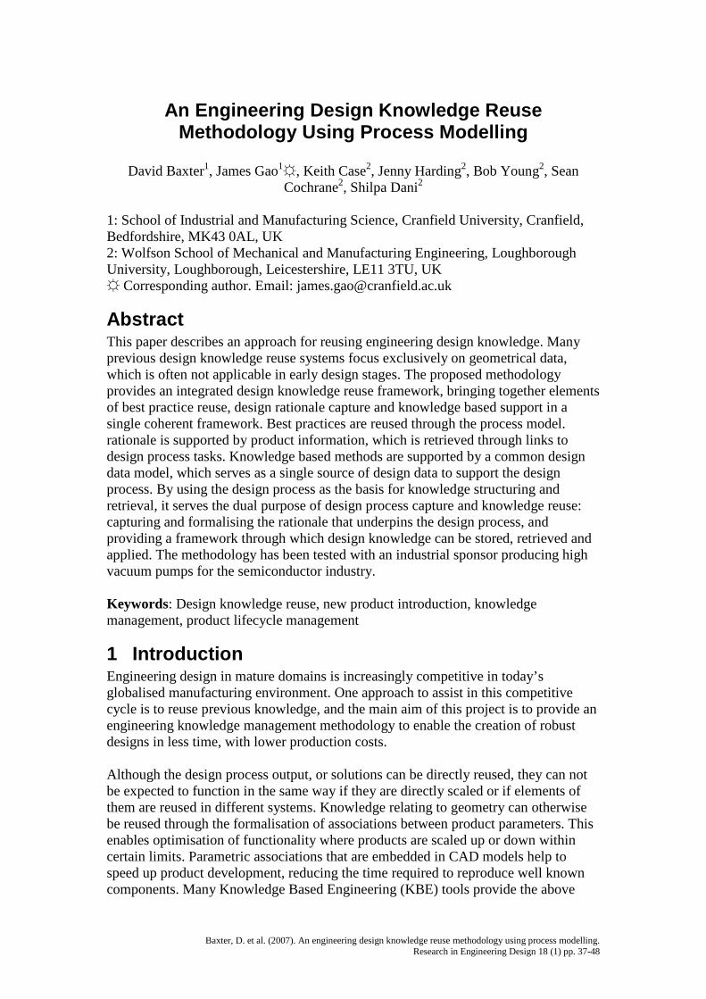
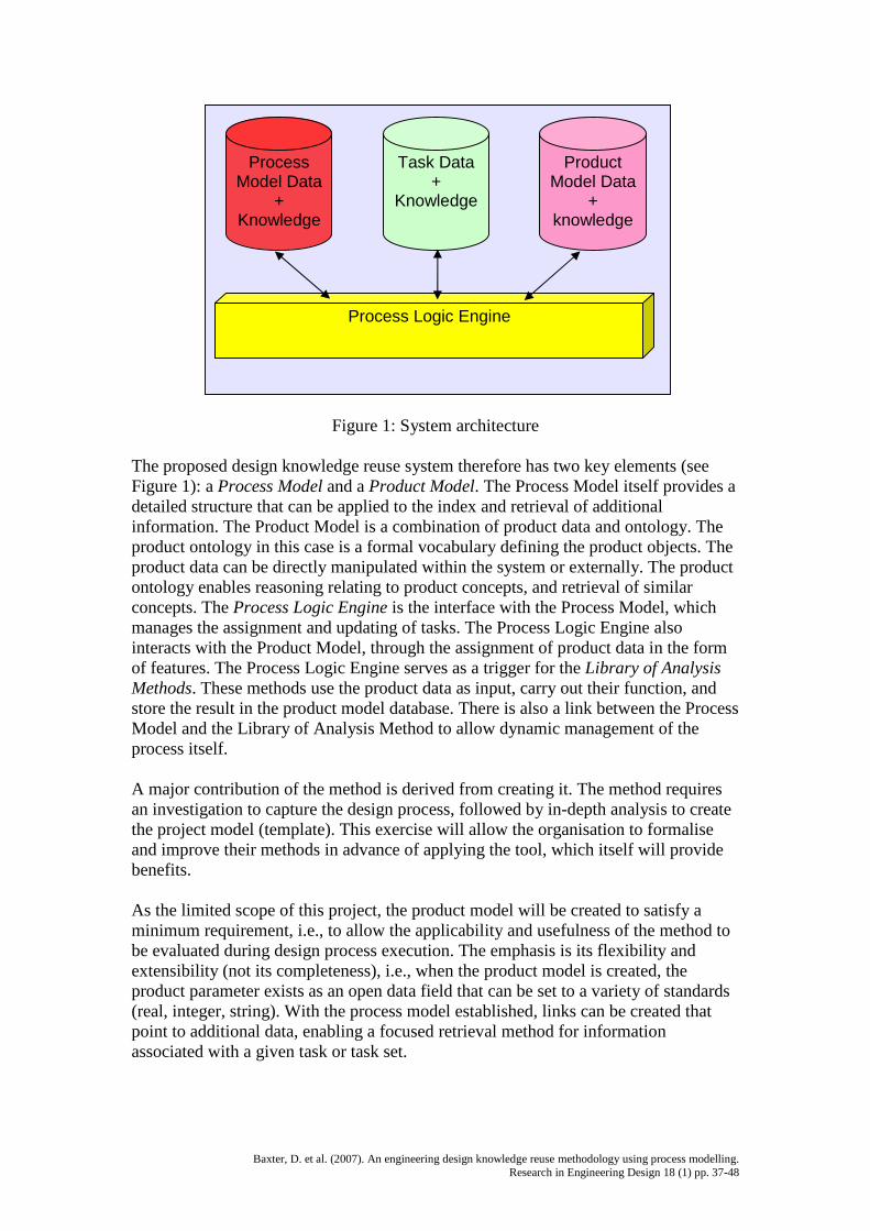
Figure 1: System architecture
The proposed design knowledge reuse system therefore has two key elements (seeFigure 1): a Process Model and a Product Model. The Process Model itself provides adetailed structure that can be applied to the index and retrieval of additionalinformation. The Product Model is a combination of product data and ontology. Theproduct ontology in this case is a formal vocabulary defining the product objects. Theproduct data can be directly manipulated within the system or externally. The productontology enables reasoning relating to product concepts, and retrieval of similarconcepts. The Process Logic Engine is the interface with the Process Model, whichmanages the assignment and updating of tasks. The Process Logic Engine alsointeracts with the Product Model, through the assignment of product data in the formof features. The Process Logic Engine serves as a trigger for the Library of AnalysisMethods. These methods use the product data as input, carry out their function, andstore the result in the product model database. There is also a link between the ProcessModel and the Library of Analysis Method to allow dynamic management of theprocess itself.
A major contribution of the method is derived from creating it. The method requiresan investigation to capture the design process, followed by in-depth analysis to createthe project model (template). This exercise will allow the organisation to formaliseand improve their methods in advance of applying the tool, which itself will providebenefits.
As the limited scope of this project, the product model will be created to satisfy aminimum requirement, i.e., to allow the applicability and usefulness of the method tobe evaluated during design process execution. The emphasis is its flexibility andextensibility (not its completeness), i.e., when the product model is created, theproduct parameter exists as an open data field that can be set to a variety of standards(real, integer, string). With the process model established, links can be created thatpoint to additional data, enabling a focused retrieval method for informationassociated with a given task or task set.
ProcessModel Data
+Knowledge
Task Data+
Knowledge
ProductModel Data
+knowledge
Process Logic Engine
Baxter, D. et al. (2007). An engineering design knowledge reuse methodology using process modelling.Research in Engineering Design 18 (1) pp. 37-48
4 Case StudyThe industrial partners supporting the research project that this paper is reporting onare involved in mature engineering domains. A detailed design process model hasbeen developed, and the supporting knowledge has been captured and added to themodel. The following section describes the approach in more detail, with a descriptionof the example.
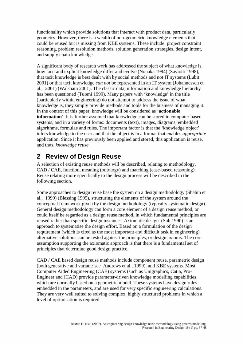
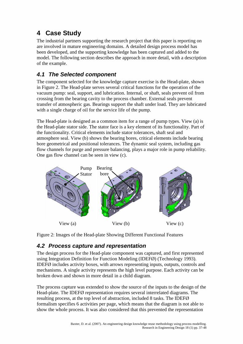
4.1 The Selected componentThe component selected for the knowledge capture exercise is the Head-plate, shownin Figure 2. The Head-plate serves several critical functions for the operation of thevacuum pump: seal, support, and lubrication. Internal, or shaft, seals prevent oil fromcrossing from the bearing cavity to the process chamber. External seals preventtransfer of atmospheric gas. Bearings support the shaft under load. They are lubricatedwith a single charge of oil for the service life of the pump.
The Head-plate is designed as a common item for a range of pump types. View (a) isthe Head-plate stator side. The stator face is a key element of its functionality. Part ofthe functionality. Critical elements include stator tolerances, shaft seal andatmosphere seal. View (b) shows the bearing bores, critical elements include bearingbore geometrical and positional tolerances. The dynamic seal system, including gasflow channels for purge and pressure balancing, plays a major role in pump reliability.One gas flow channel can be seen in view (c).
View (a) View (b) View (c)
Figure 2: Images of the Head-plate Showing Different Functional Features
4.2 Process capture and representationThe design process for the Head-plate component was captured, and first representedusing Integration Definition for Function Modeling (IDEFØ) (Technology 1993).IDEFØ includes activity boxes, with arrows representing inputs, outputs, controls andmechanisms. A single activity represents the high level purpose. Each activity can bebroken down and shown in more detail in a child diagram.
The process capture was extended to show the source of the inputs to the design of theHead-plate. The IDEFØ representation requires several interrelated diagrams. Theresulting process, at the top level of abstraction, included 8 tasks. The IDEFØformalism specifies 6 activities per page, which means that the diagram is not able toshow the whole process. It was also considered that this prevented the representation
PumpStator
Bearingbore

Baxter, D. et al. (2007). An engineering design knowledge reuse methodology using process modelling.Research in Engineering Design 18 (1) pp. 37-48
of both context and detail in a single representation. The IDEFØ series enabled anobserver to gain an understanding of what is happening during the process. Thiswould be adequate if the system analysis task was required for that purpose (as it is ina system design project). The requirement of the process representation method in thisscenario is that it will enable the process to be reapplied, and knowledge about it to bereused. For this purpose the context is important, and so combination of the 6-nodelimit along with the complex array of link types shown in an IDEFØ diagramprompted the search for an alternative. It should be emphasised that is not a lacking inthe process logic that prompted the selection of an alternative process modellingmethod. The change was driven by the need to understand, at a glance, an overview ofthe process and its context. This requirement is in support of system usability.
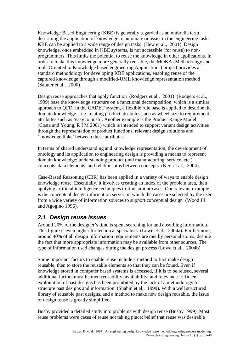
The headplate design process was later modelled using the Design Roadmap (DR)Framework (Park and Cutosky 1999). The DR representation consists of two nodetypes, task (the task itself to be enacted) and feature (which is a task data set). Linktypes include precedence, abstraction and constraints. Precedence shows order of taskexecution, and likely iteration. Abstraction relates to the capability for a sequence ofelements to be represented by a single element. Constraint links connect featurenodes, and show that a constraint exists. Note that the term ‘feature’ is the name givento the data objects included in the process model. It bears no relation to other uses ofthe term ‘feature’ in the engineering domain.
Figure 3 shows a view of Head-plate Design Tasks, modelled using DR Framework,with some of the Features and their attribute slots visible. Iterations, feedback andside-effects have been removed for simplicity. Within the Head-plate design task,both sequential and concurrent activities take place. Data that is required by later tasksis recorded in the features. For example, the Bearing Bore Feature contains data (sizeand tolerance) that will be used in the lubrication system design Task (see top ofFigure 3). This same data set could also be used as an input to a manufacturabilityanalysis Task, i.e., data sets can be called by any Task object. The main objective ofthe Features shown in this diagram is to provide data required by subsequent tasks. Itis the Feature that triggers the Task. If a data set is required but not complete, the taskwill not be initiated.
TaskDrive Layout
(motor, gears,shaft)
TaskLubrication system(thrower, channels)
layout
TaskLip seal layout
TaskDynamic seal
design
TaskBearing bore layout
TaskHeadplate Stator
Layout
Feature: Bearing Bore
Size (diameter, depth)
Bore Tolerance
Geometry Tolerance
Feature: h/p Stator
Size (diameter, depth)
Bore Tolerance
Geometry Tolerance
Feature: Drive
Gear position
Motor fixing
Shaft size
Feature: ThrowerSize:diameter
depth
Tolerances
Feature: Gas flow
Channel location
N2 Flow rate
Feature: Lip Seal
Internal diameter
External diameter
Tolerances
x
x
x
x
x
x
x
x
x
x
x
x
x
x
x
x
x
Baxter, D. et al. (2007). An engineering design knowledge reuse methodology using process modelling.Research in Engineering Design 18 (1) pp. 37-48
Figure 3: The Head-plate Design Tasks Modelled Using Design Roadmap Framework
4.3 Parameterised product modelThe process representation method allows data to be carried through the process usingthe Feature nodes. Within this application, the data that is represented in the Featurenodes is both created and used by the Tasks. For example, the RequirementsSpecification Task produces a fully populated engineering requirements data set.Other Tasks use this Feature data as an input. It is possible to have a Task creatingmultiple Features, and for a subsequent Task to use multiple input Features.
The data handling provided by the process model enables the Parameters of theproduct to be created through the enactment of the design process. An implicit methodfor the handling of the data set is embedded in the design process, i.e., what theparameters are, where they are created, and where they are used. The explicit methodsapplied to the storage and manipulation of the data set are not made clear, so must bedefined.
A full implementation of this method may involve several thousand Parameters.Grouping the parameters into Sets (Objects) could ease the retrieval and reuse process.Rather than call an individual Parameter, an Object could be called. These Objects arecalled by the Features in the Process Model. Using an inheritance model, it will bepossible to treat the Parameter Set as a hierarchy of Objects. The attributes of theobjects are populated through the product design process.
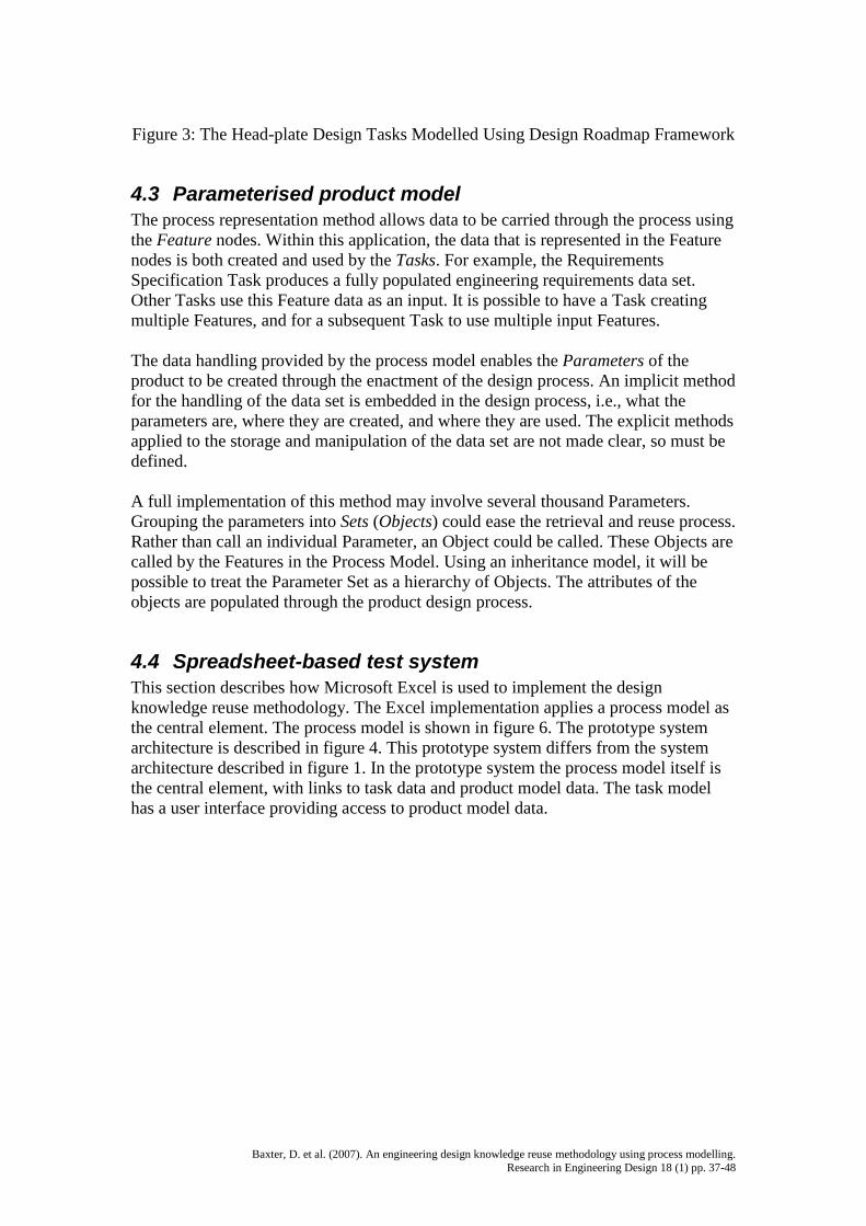
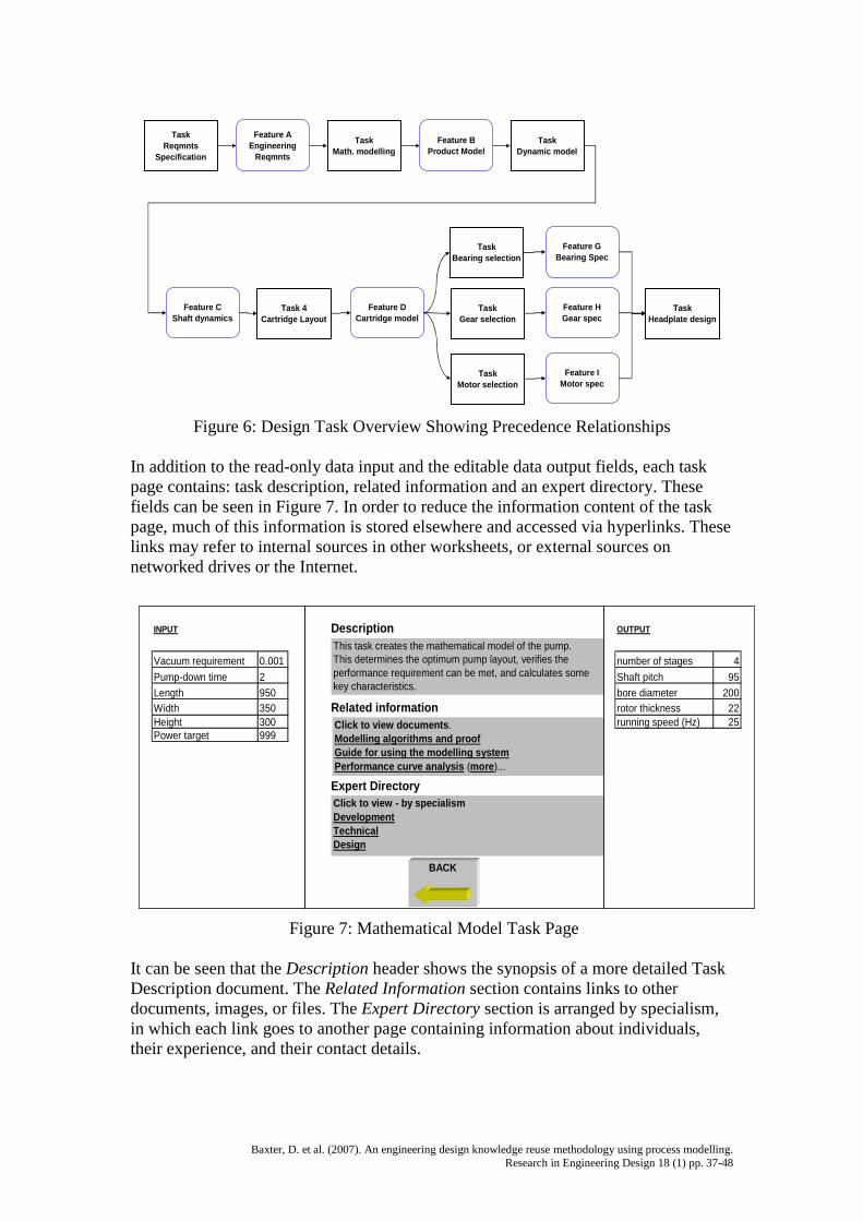
4.4 Spreadsheet-based test systemThis section describes how Microsoft Excel is used to implement the designknowledge reuse methodology. The Excel implementation applies a process model asthe central element. The process model is shown in figure 6. The prototype systemarchitecture is described in figure 4. This prototype system differs from the systemarchitecture described in figure 1. In the prototype system the process model itself isthe central element, with links to task data and product model data. The task modelhas a user interface providing access to product model data.
Baxter, D. et al. (2007). An engineering design knowledge reuse methodology using process modelling.Research in Engineering Design 18 (1) pp. 37-48
Figure 4. Prototype System Architecture
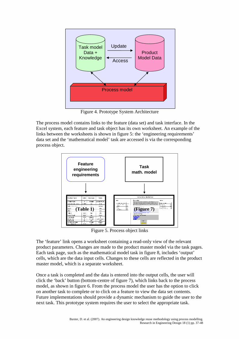
The process model contains links to the feature (data set) and task interface. In theExcel system, each feature and task object has its own worksheet. An example of thelinks between the worksheets is shown in figure 5: the ‘engineering requirements’data set and the ‘mathematical model’ task are accessed is via the correspondingprocess object.
Featureengineering
requirements
Taskmath. model
Figure 5. Process object links
The ‘feature’ link opens a worksheet containing a read-only view of the relevantproduct parameters. Changes are made to the product master model via the task pages.Each task page, such as the mathematical model task in figure 8, includes ‘output’cells, which are the data input cells. Changes to these cells are reflected in the productmaster model, which is a separate worksheet.
Once a task is completed and the data is entered into the output cells, the user willclick the ‘back’ button (bottom-centre of figure 7), which links back to the processmodel, as shown in figure 6. From the process model the user has the option to clickon another task to complete or to click on a feature to view the data set contents.Future implementations should provide a dynamic mechanism to guide the user to thenext task. This prototype system requires the user to select the appropriate task.
Task modelData +
KnowledgeProduct
Model Data
Process model
Update
Access
(Table 1) (Figure 7)
Baxter, D. et al. (2007). An engineering design knowledge reuse methodology using process modelling.Research in Engineering Design 18 (1) pp. 37-48
TaskMath. modelling
Feature AEngineering
Reqmnts
TaskMotor selection
TaskGear selection
Task 4Cartridge Layout
TaskBearing selection
TaskHeadplate design
TaskDynamic model
TaskReqmnts
Specification
Feature BProduct Model
Feature CShaft dynamics
Feature DCartridge model
Feature GBearing Spec
Feature HGear spec
Feature IMotor spec
Figure 6: Design Task Overview Showing Precedence Relationships
In addition to the read-only data input and the editable data output fields, each taskpage contains: task description, related information and an expert directory. Thesefields can be seen in Figure 7. In order to reduce the information content of the taskpage, much of this information is stored elsewhere and accessed via hyperlinks. Theselinks may refer to internal sources in other worksheets, or external sources onnetworked drives or the Internet.
INPUT Description OUTPUT
Vacuum requirement 0.001 number of stages 4Pump-down time 2 Shaft pitch 95Length 950 bore diameter 200Width 350 Related information rotor thickness 22Height 300 running speed (Hz) 25Power target 999
Expert Directory
BACK
This task creates the mathematical model of the pump.This determines the optimum pump layout, verifies theperformance requirement can be met, and calculates somekey characteristics.
more
Click to view documents.Modelling algorithms and proofGuide for using the modelling systemPerformance curve analysis (more)...
Click to view - by specialismDevelopmentTechnicalDesignModelling
Figure 7: Mathematical Model Task Page
It can be seen that the Description header shows the synopsis of a more detailed TaskDescription document. The Related Information section contains links to otherdocuments, images, or files. The Expert Directory section is arranged by specialism,in which each link goes to another page containing information about individuals,their experience, and their contact details.
Baxter, D. et al. (2007). An engineering design knowledge reuse methodology using process modelling.Research in Engineering Design 18 (1) pp. 37-48
Feature Name Data Data type Units
Product type 1 integer product-type
Vacuum requirement 0.001 real mbar
Pump-down time 2 real seconds
Length 950 real mm
Width 350 real mm
Height 300 real mm
Power target 999 real Watts
Cost target 1500 currency $pump type 1 integer pump-typeShaft pitch 95 real mmnumber of stages 4 integer integerbore diameter 200 real mm
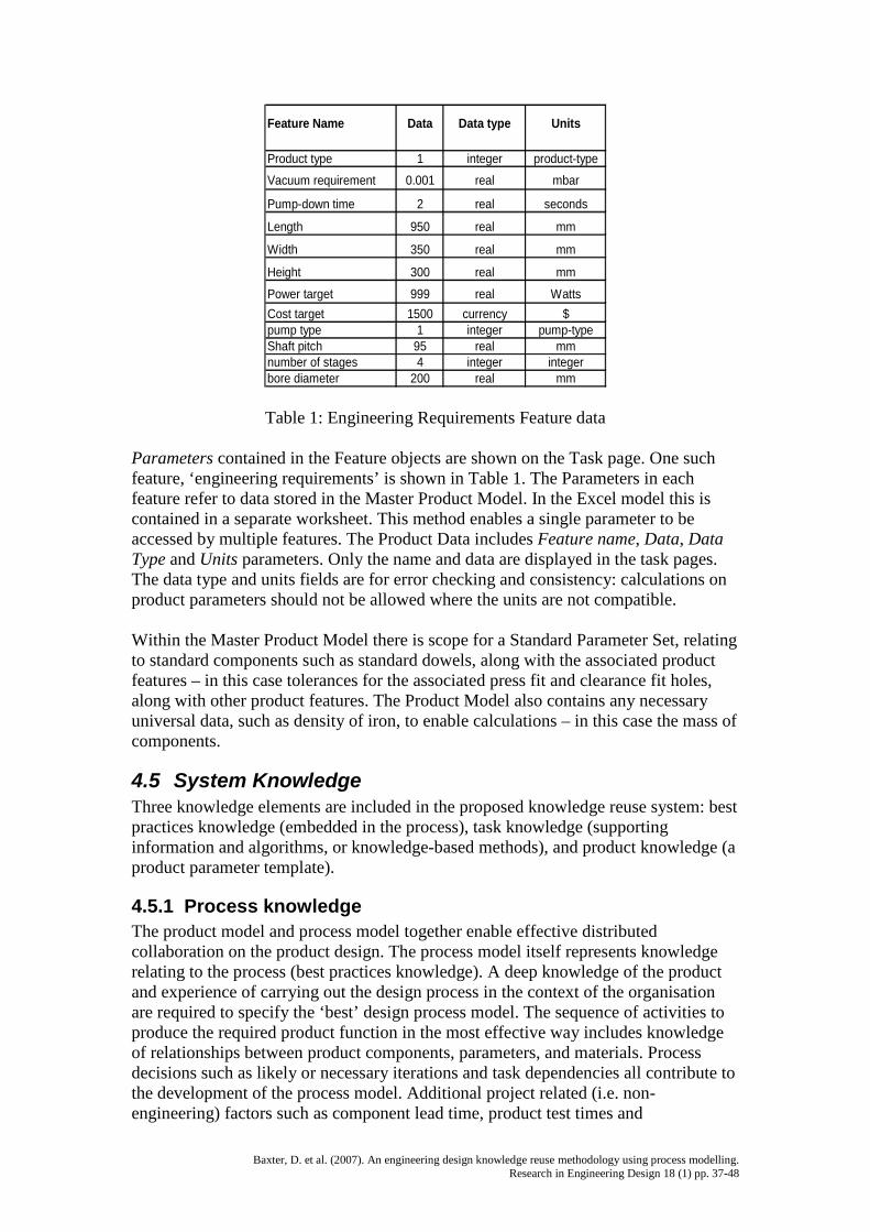
Table 1: Engineering Requirements Feature data
Parameters contained in the Feature objects are shown on the Task page. One suchfeature, ‘engineering requirements’ is shown in Table 1. The Parameters in eachfeature refer to data stored in the Master Product Model. In the Excel model this iscontained in a separate worksheet. This method enables a single parameter to beaccessed by multiple features. The Product Data includes Feature name, Data, DataType and Units parameters. Only the name and data are displayed in the task pages.The data type and units fields are for error checking and consistency: calculations onproduct parameters should not be allowed where the units are not compatible.
Within the Master Product Model there is scope for a Standard Parameter Set, relatingto standard components such as standard dowels, along with the associated productfeatures – in this case tolerances for the associated press fit and clearance fit holes,along with other product features. The Product Model also contains any necessaryuniversal data, such as density of iron, to enable calculations – in this case the mass ofcomponents.
4.5 System KnowledgeThree knowledge elements are included in the proposed knowledge reuse system: bestpractices knowledge (embedded in the process), task knowledge (supportinginformation and algorithms, or knowledge-based methods), and product knowledge (aproduct parameter template).
4.5.1 Process knowledgeThe product model and process model together enable effective distributedcollaboration on the product design. The process model itself represents knowledgerelating to the process (best practices knowledge). A deep knowledge of the productand experience of carrying out the design process in the context of the organisationare required to specify the ‘best’ design process model. The sequence of activities toproduce the required product function in the most effective way includes knowledgeof relationships between product components, parameters, and materials. Processdecisions such as likely or necessary iterations and task dependencies all contribute tothe development of the process model. Additional project related (i.e. non-engineering) factors such as component lead time, product test times and
Baxter, D. et al. (2007). An engineering design knowledge reuse methodology using process modelling.Research in Engineering Design 18 (1) pp. 37-48
organisational factors such as the availability of expertise and systems also contributeto the process model. As such, the process model represents one of the knowledgeelements embedded within the proposed method.
4.5.2 Task knowledgeThe second knowledge element is task knowledge. This includes information andautomation. Supporting information is available to support the designer in completingthe task. It includes general notes, formal design documentation, images, tables, andcatalogues. Informal notes and annotation, or rationale, may be added during theprocess. The combination of these elements is intended to be brought together andedited for reuse in the next generation product template to support design decisions.Automation, in this context, is the application of knowledge based methods oralgorithms to manipulate the product data. These algorithms take parameters from theproduct model as inputs, make calculations on them, and store them as new orupdated parameters.
4.5.3 Product knowledgeThe third knowledge element is referred to as product knowledge. In thisimplementation of the system, the product knowledge is represented by the parameterset. This enables the application of a product template to the development of a newproduct variant. The template can be applied at a variety of levels. The first is ‘datalabels only’, to develop a whole new product of the same type (such as the nextgeneration product in the range). The second level can be applied on a broad spectrumdepending on the constraints: using a partial data model to develop a new productfamily member (such as a different pumping speed or application variant). Clearly theapplication of the partial data model exists within certain limits, which must bedefined for each product type.
One aim is to extend the product knowledge element to include a product ontology torepresent a collectively defined lexicon of terms, agreed parameter ranges andrelationships between terms. This should improve the understanding of the designprocess, and also extend the capability for managing the design process in adistributed manner.
4.5.4 Relationship with KBEThis system is not itself a KBE system; however it does have the capability to includeKBE methods. The main contribution in terms of KBE is a system to provide thecapability to define multiple input and output data sets for analysis by multiple KBEsystems. The definition of the product model will be shaped by the organisationalrequirements at the early design stages. Product model parameters and structure(content of individual data sets) will be defined according to the needs of the process,including KBE systems. The process model supports KBE by including the requiredtasks. Task knowledge includes KBE methods, or in the case of external systems,support for carrying out the task. Automation of the task, including data input / output,represents system task knowledge.
4.6 Application and extension of the DR methodThe process representation method is based on the DR (Design Roadmap) method. Itshould be noted that the implementation applies only a part of the DR framework. The
Baxter, D. et al. (2007). An engineering design knowledge reuse methodology using process modelling.Research in Engineering Design 18 (1) pp. 37-48
basic process logic was applied: a data object precedes (and is consumed by) a taskobject. Precedence and abstraction links were the only types applied to the example.The other DR link types (feedback, feedforward and constraint relationships) wouldadd value to an extended process model. The DR process logic was also notrigorously defined in this test system; the main objective being the processrepresentation. It is therefore not possible to show alternate views of the process(design structure matrix representation is an option in the DR system).
One limitation of the DR method is that there is no method to link task knowledge,including supporting information and computational methods, to the process model.The approach described in this paper provides a method to link task knowledge to theprocess model. Supporting information is stored and indexed with relation to tasks.Through interaction with a product model, computational methods can also be appliedto task support. The product model concept further extends the DR method, bysuggesting that product and process data are stored separately.
5 Evaluation of the proposed methodology and itspotential applications
Within variant design domains, where similar products are designed for severalgenerations, this approach can provide significant benefit. The application of processtemplates along with the capability to store and apply additional information and datawill significantly enhance the reuse of product knowledge, and so improve the productdevelopment effort. If the product in question is highly complex, and also highlysimilar to the last generation, the organisation will gain most benefit from theapplication of KBE technologies that aid the synthesis and analysis of the nextgeneration product. The method proposed here, in that case, could be applied to themanagement of design and project knowledge, especially unstructured knowledge thatsupports product development. The calculations (KBE driven analysis) will be carriedout using the proprietary KBE systems. So this method will be of use to the productdevelopment team, but more benefits will be gained from the application of KBEsystems. The management of structured knowledge provided by this approach willallow the product development team to keep a central data store that tracks theproduct development, enabling better coordination of distributed teams. The processmanagement methods and the methods to store and retrieve unstructured informationwill also serve a useful purpose. The significance of KBE and geometry basedmethods is due to the high relative importance of geometry in later stages of thedesign process 8, and the scale of the detailed design effort when compared toconceptual design, particularly with highly complex products.
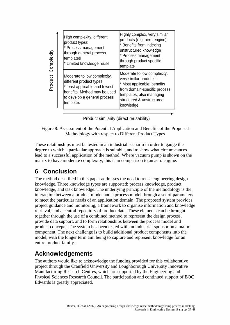
The (project) model context relates directly to the product. A process map template iscreated for a specific product type, just as the product model template. If the type ofproduct differs widely from one generation to the next, then the amount of detailrelevant to the next product will be greatly reduced. There comes a point at which thebenefits to be gained from applying such a context specific knowledge reuse tool areovertaken by the costs, when compared with following a general design process. Insuch cases, the method can be used to implement a general design (or innovation)methodology. It can also be used to store and manage design data through the process.This relationship is described in the matrix in figure 8.
Baxter, D. et al. (2007). An engineering design knowledge reuse methodology using process modelling.Research in Engineering Design 18 (1) pp. 37-48
High complexity, differentproduct types:* Process managementthrough general processtemplates* Limited knowledge reuse
Highly complex, very similarproducts (e.g. aero engine):* Benefits from indexingunstructured knowledge* Process managementthrough product specifictemplate
Moderate to low complexity,different product types:*Least applicable and fewestbenefits. Method may be usedto develop a general processtemplate.
Moderate to low complexity,very similar products:* Most applicable: benefitsfrom domain-specific processtemplates, also managingstructured & unstructuredknowledge
Product similarity (direct reusability)
Pro
duct
Com
plex
ity
Figure 8: Assessment of the Potential Application and Benefits of the ProposedMethodology with respect to Different Product Types
These relationships must be tested in an industrial scenario in order to gauge thedegree to which a particular approach is suitable, and to show what circumstanceslead to a successful application of the method. Where vacuum pump is shown on thematrix to have moderate complexity, this is in comparison to an aero engine.
6 ConclusionThe method described in this paper addresses the need to reuse engineering designknowledge. Three knowledge types are supported: process knowledge, productknowledge, and task knowledge. The underlying principle of the methodology is theinteraction between a product model and a process model through a set of parametersto meet the particular needs of an application domain. The proposed system providesproject guidance and monitoring, a framework to organise information and knowledgeretrieval, and a central repository of product data. These elements can be broughttogether through the use of a combined method to represent the design process,provide data support, and to form relationships between the process model andproduct concepts. The system has been tested with an industrial sponsor on a majorcomponent. The next challenge is to build additional product components into themodel, with the longer term aim being to capture and represent knowledge for anentire product family.
AcknowledgementsThe authors would like to acknowledge the funding provided for this collaborativeproject through the Cranfield University and Loughborough University InnovativeManufacturing Research Centres, which are supported by the Engineering andPhysical Sciences Research Council. The participation and continued support of BOCEdwards is greatly appreciated.
Baxter, D. et al. (2007). An engineering design knowledge reuse methodology using process modelling.Research in Engineering Design 18 (1) pp. 37-48
ReferencesAndrews, P., Shahin, T. and Sivaloganathan, S. (1999) Design reuse in a CAD
environment -- Four case studies. Computers & Industrial Engineering. 37, 1-2.105-9
Backer, T., Siegel, T., Rabin, P. and McGrath, T. (1995) Avoiding the redesign trap:standard design processes improve design quality and reuse. In: anonymous(editors.), AIAA 95-1003,AIAA, Washington, pp. 414-422.
Balasubramanian, P., Nochur, K., Henderson, J. and Kwan, M. (1999) Managingprocess knowledge for decision support. Decision Support Systems. 27, 1. 145-62
Baxter, D.I. and Gao, J.X. (2004) Process based representation for design knowledge,In: Proceedings of the 2nd International Conference on Manufacturing research2004 (ICMR 2004). Sheffield Hallam University, Sheffield, UK.
Baxter, D.I. and Gao, J.X. (2005) Process based design knowledge reuse throughprocess and product representation, In: Proceedings of the 12th CIRP LifeCycle Engineering Seminar (CIRP LCE) 2005. Grenoble, France.
Blessing, L.T.M. (1995) A process-based approach to design. Colloquium Digest-IEE.49.
BURGE, J.E. and BROWN, D.C. (2002) INTEGRATING DESIGN RATIONALEWITH A PROCESS MODEL, In: International Workshop on Agents in Design,WAID’02, MIT, Cambridge, USA.
Busby, J.S. (1999) The Problem with Design Reuse: An Investigation into Outcomesand Antecedents. Journal of Engineering Design. 10, 3. 277-97
Clarkson, P.J. and Hamilton, J.R. (2000) Signposting, A Parameter-driven Task-basedModel of the Design Process. Research in Engineering Design. 12, 1. 18-38
Classen, A. and Lopez, L. (1998) New product introduction between twogeographically dispersed entities, In: Engineering and TechnologyManagement, 1998. Pioneering New Technologies: Management Issues andChallenges in the Third Millennium. IEMC '98 Proceedings. InternationalConference on. Rensselaer Polytechnic Institute. IEEE
Concheri, G. and Milanese, V. (2000) MIRAGGIO: a system for the dynamicmanagement of product data and design models. Advances in EngineeringSoftware. 32, 527-43
Costa, C.A. and Young, R I M (2001) Product range models supporting designknowledge reuse. Proceedings of the Institution of Mechanical Engineers - PartB - Engineering Manufacture. 215, 3. 323-38
Finger, S. (1998) Design reuse and design research - keynote paper, In: EngineeringDesign Conference '98. Brunel University, UK. Professional EngineeringPublishing Ltd
Gardam, A. and Burge, S.E. (1997) Changes in the Engineering Design Process, In:Advances in Maufacturing Technology XI. Glasgow Caledonian University.
Gorti, Gupta, Kim, Sriram and Wong (1998) An object-oriented representation forproduct and design processes. Computer-Aided Design. 30, 7. 489-501
Hansen, C. and Andreasen, M. (2002) The content and nature of a design concept, In:NordDesign 2002: Visions and values in engineering design. NorwegianUniversity of Science & Technology, Trondheim, Norway.
Harding, J.A., Popplewell, K. and Cook, D. (2003) Manufacturing system engineeringmoderator: an aid for multidiscipline project teams. International Journal ofProduction Research. 41, 9. 1973-86
Baxter, D. et al. (2007). An engineering design knowledge reuse methodology using process modelling.Research in Engineering Design 18 (1) pp. 37-48
Hayashi, N. and Herman, G. (2002) A coordination-theory approach to exploringprocess alternatives for designing differentiated products, In: EngineeringManagement Conference, 2002. IEMC '02. 2002 IEEE International.IEEE
Hew, K.P., Fisher, N. and Awbi, H.B. (2001) Towards an integrated set of designtools based on a common data format for building and services design.Automation in Construction. 10, 4. 459-76
Hicks, B.J., Culley, S.J., Allen, R.D. and Mullineux, G. (2002) A framework for therequirements of capturing, storing and reusing information and knowledge inengineering design. International Journal of Information Management. 22, 4.263-80
Huang, H.-Z. and Gu, Y.-K. (2006) Development mode based on integration ofproduct models and process models. Concurrent Engineering: Research andApplications. 14, 1. 27-34
Inns, T. and Neville, P. (1998) Establishing a company-level design process tofacilitate design reuse, In: Engineering Design Conference. Brunel University,UK.
Johannessen, J.-A. , Olaisen, J. and Olsen, B. (2001) Mismanagement of tacitknowledge: the importance of tacit knowledge, the danger of informationtechnology, and what to do about it. International Journal of InformationManagement. 21, 3-20
Kalpic and Bernus (2002) Business process modelling in industry--the powerful toolin enterprise management. Computers in Industry. 47, 3. 299-318
Kerr, C., Roy, R. and Sackett, P. (2004) A product ontology for automotive seatspecification, In: The 2004 ASME International Design Engineering TechnicalConferences & The Computer and Information in Engineering Conference(ASME DETC/CIE 2004) – 30th Design Automation Conference (DAC). SaltLake City, Utah, USA.
Knott, R.P., Merunka, V. and Polak, J. (2003) The role of object oriented processmodeling in requirements engineering phase of information systemsdevelopment, In: EFITA 2003. Debrecen, Hungary.
Leake, D.B. and Wilson, D.C. (2001) A case-based framework for interactive captureand reuse of design knowledge. Applied Intelligence. 14, 77-94
Li, Y., Shao, X., Li, P. and Liu, Q. (2004) Design and implementation of a process-oriented intelligent collaborative product design system. Computers in Industry.53, 2. 205-29
Lowe, A., McMahon, C. and Culley, S. (2004a) Information access, storage and useby engineering designers - Part 1. Engineering Designer. March/April, 30-2
Lowe, A., McMahon, C. and Culley, S. (2004b) Information access, storage and useby engineering designers - Part 2. Engineering Designer. May/June, 23-5
Lu, S., Cai, J., Burkett, W. and Udwadia, F. (2000) A Methodology for CollaborativeDesign Process and Conflict Analysis. ANNALS- CIRP. 49, 1. 69-74
Lubit, R. (2001) The keys to sustainable competitive advantage: Tacit knowledge andknowledge management. Organizational Dynamics. 29, 4. 164-78
Markus, M.L. (2001) Toward a theory of knowledge reuse: types of knowledge reusesituations and factors in reuse success. Journal of Management InformationSystems. 18, 1. 57-93
Matsumoto, I.T., Stapleton, J., Glass, J. and Thorpe, T. (2005) A knowledge-capturereport for multidisciplinary design environments. Journal of KnowledgeManagement. 9, 3. 83-92
Baxter, D. et al. (2007). An engineering design knowledge reuse methodology using process modelling.Research in Engineering Design 18 (1) pp. 37-48
National InstituteofStandardsand Technology (1993) Integration Definition ForFunction Modeling (IDEF0).
Nonaka, I. (1994) A Dynamic Theory of Organizational Knowledge Creation.Organization Science. 5, 1. 14-28
Paashuis, V. and Boer, H. (1997) Organizing for concurrent engineering: anintegration mechanism framework. Integrated Manufacturing Systems. 8, 2. 79-89
Pakovich, N. and Marjanovich, D. (2001) Considering an object oriented approach tothe design process planning. International journal of technology management.21, 25-42
Park, H. and Cutosky, M.R. (1999) Framework for modeling dependencies incollaborative engineering processes. Research in engineering design. 11, 2. 84-102
Pavkovic, N. and Marjanovic, D. (2000) Entities in the object oriented design processmodel, In: International Design Conference - Design 2000. Dubrovnik.
Ramesh, B. and Tiwana, A. (1999) Supporting collaborative process knowledgemanagement in new product development teams. Decision Support Systems. 27,213-35
Rodgers, P.A., Caldwell, N.H.M., Clarkson, P.J. and Huxor, A.P. (2001) Themanagement of concept design knowledge in modern product developmentorganizations. International Journal of Computer Integrated Manufacturing. 14,1. 108-15
Rodgers, P.A., Huxor, A.P. and Caldwell, N.H.M. (1999) Design Support UsingDistributed Web-Based AI Tools. Research in Engineering Design. 11, 1. 31-44
Röhl, P., Kolonay, R., Irani, R., Sobolewski, M. and Kao, K. (2000) A FederatedIntelligent Product Environment, In: 8th AIAA/USAF/NASA/ISSMOSymposium on Multidisciplinary Analysis and Optimization. Long Beach, CA.
Sainter, P., Oldham, K., Larkin, A., Murton, A. and Brimble, R. (2000) ProductKnowledge Management within Knowledge-Based Engineering Systems, In:ASME 2000 Design Engineering Technical Conference. Maryland, US. ASME
Saviotti, P.P. (1998) On the dynamics of appropriability, of tacit and of codifiedknowledge. Research Policy. 26, 843-56
Schofield, M. and Gregory, M. (2002) The impact of architectural uncertainty onproduct introduction in dispersed environments, In: Engineering ManagementConference, 2002. IEMC '02. 2002 IEEE International.IEEE
Shahin, T.M.M., Andrews, P.T.J. and Sivaloganathan, S. (1999) A design reusesystem. Proceedings of the Institution of Mechanical Engineers, Part B: Journalof Engineering Manufacture. 213, 6. 621-7
Shooter, S., Keirouz, W., Szykman, S. and Fenves, S. (2000) A Model for the Flow ofDesign Information in Product Development. Engineering with Computers. 16,3-4. 178-94
Sim, S.K. and Duffy, A.H. (2003) Towards an ontology of generic engineering designactivities. Research in Engineering Design. 14, 200-23
Sivaloganathan, S. and Shahin, T.M.M. (1999) Design reuse: an overview.Proceedings of the Institution of Mechanical Engineers - Part B - EngineeringManufacture. 213, 7. 641-55
Suh, N.P. (1990) The Principles of Design. Oxford University Press, Oxford.Tate, D. and Nordlund, M. (1996) A design process roadmap as a general tool for
structuring and supporting design activities, In: Second World Conference onIntegrated Design and Process Technology. Austin, Texas, USA.
Baxter, D. et al. (2007). An engineering design knowledge reuse methodology using process modelling.Research in Engineering Design 18 (1) pp. 37-48
Tucker, D. and Hackney, R. (2000) Towards the integration of concurrent engineeringenvironments within organisational strategy. Journal of ManagementDevelopment. 19, 3. 179-90
Tuomi, I. (1999) Data Is More Than Knowledge: Implications of the ReversedKnowledge Hierarchy for Knowledge Management and OrganizationalMemory. Journal of Management Information Systems. 16, 3. , 103
Salminen, V., Yassine, A. and Riitahuhta, A. (2000) A strategic managementframework for collaborative product development, In: 4th Internationalconference on engineering design and automation (ED&A). Orlando, Florida.
Walsham, G. (2001) Knowledge Management: The Benefits and Limitations ofComputer Systems. European Management Journal. 19, 6. 599-608
Wood III, W.H. and Agogino, A.M. (1996) Case-based conceptual design informationserver for concurrent engineering. Computer-Aided Design. 28, 5. 361-9
Wujek, B., Koch, P. and Chiang, W. (2000) A workflow paradigm for flexible designprocess configuration in fiper. AIAA-2000-4868.
Xu, Z., Frazer, J. and Tang, M. (2002) Novel design methodology supporting productlife-cycle design. Computers in Industry. 49, 253-65
Yassine, A.A. and Falkenburg, D.R. (1999) A framework for design processspecifications management. Journal of Engineering Design. 10, 3. 223-34
Zdrahal, Z., Mulholland, P., Domingue, J. and Hatala, M. (2000) Sharing engineeringdesign knowledge in a distributed environment. BEHAVIOUR &INFORMATION TECHNOLOGY. 19, 3. 189-200