Embed Size (px)
Citation preview
An Expert System for Diagnosis and Maintenance in FMS
V. D. Majstorovic, V. R. Milacic (1); Mechanical Engineering Faculty, Beograd University/Yugoslavia Received on January 25,1989
ABSTRACT; The building of the expert system for diagnosis and maintenance in FMS is a very complex interdisciplinary engineering task. In InterCeAT (International Center for Advanced Technology) a model of an expert system called EXMAS (Expert Maintenance System) has been developed for conceptual diagnosis and maintenance of FElS working stations. The elements of the theory of automata, knowledge blocks, artificial intelligence tools and techniques have been used in the building of this model. I n its present stage the model is developed a s the prototype for certain working statlons, s o that later suiiie o f its modules may be linkcd with its higher levels (betvrrn indivldual working s L a L i o n s ) and the integrated software product for other FMS functions.
KEY WORDS: Diagnosis, Expert Systems. F>IS, Maintenance.
1. THE APPROACHES TO THE DEVELOPMENT OF DIAGNOSTIC SYSTEHS - RESEARCH PROBLEM DEFINITION FMS to-day represent the highest level of flexible
automation widespread in industrial environment. These are computerised plants with high level data processing distribution and the automatic flow of material, consisting from different mechatronic working stations.
The development of the concept of “un-manned” machining stations gave the basic impulse for the development of diagnostic systems at all technoloei- cal levels in flexible manufacture. Kobayashi [ I ] attaches the greatest importance for the development of this concept to the following three factors: the flexibility, reliability and diagnostic system. The theoretical fundaments of diagnostic systems for manufacturing systems have been set down by prof. Yoshikava [2]. The more recent characteristic approaches include: the use of fuzzy sets [3], causal model of working stations [4] and the use of A1 in the selection of diagnostic signals [5,61.
The diagnostic system of working stations is developed o n theoretical and experimental analysis of its processes and appearances, Fig.1. With such working station diagnostic model the diagnosis is made on the basis of comparative analyses o f real behaviour and simul.ated diagnostic parameters. This paper has two parts. The fj.rsr: part describes deve- loped EXNAS model i l l detail. The second p o r t presents some results of practical tests.
2. EXNAS MODEL
may be idenlified: designing, production and exploi- tation. The first two, a s a rule, relate to the producers and the third one to users.For this concept a multilevel mainLenance model has been developed which defines the engineering approaches to: (i)main- tenance design, (ii)maintenance technology design,and (iii)mainLenance planning and control [ O ] . The model is based o n a mechanical system, and higher levels relate to the above stated groups of engineering activites (71.
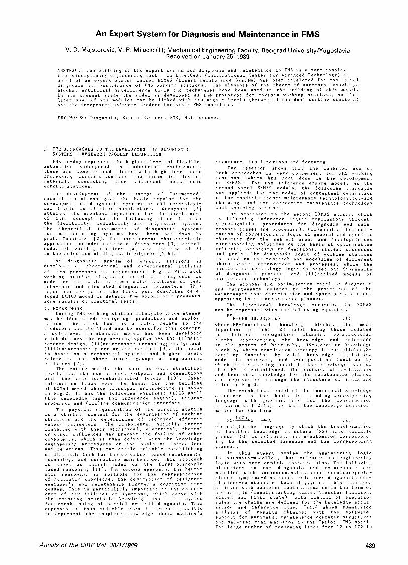
The entire model, the same a s each stratified level, has its own inputs. outputs and connections with the superior-subordinated levels [ l o ] . ‘These information flows were the basis for the building of EXNAS model whose principal architecture is shown i n F i g . 2 . It has the following entities: (i)ES shell (the knowledge base and inference engine). (ii)the processor and (iii.)the communication i.nterface.
The physical organisation of the working station is a starting element: for the description of machine structure and thc determining of technical effecti- veness parameters. The components, mutually inter- connected with their mechanical, electrical, thermal or other influences may prevent the failure of other components, which is then defined with the knowledge engineering procedures o n the basis of connections and relations. This may enable reliable establishing of diagnosis both for the condition-based maintenance technology and corrective maintenance. This approach is known a s causal model o r the first-principle based reasoning [ll]. The second approach, the heuri- stic reasoning is suitable for the representation of heuristic knowledge, the description of designer- enginecr’s and maintenance planner‘s cognitive pro- cesses. This is particularly important in the appear- oncc o f n e w failures or symptoms, rrh1r.h serve with the existing heuristic knowledge about the system for establishing of partial o r full diagnosis. This approach is thus suitable when it is not possible to represent the complete knowledge about machine‘s
During FElS working station lifecycle three stages
structure, its functions and features. Our research shows that thc combined use of
both approaches is very convenient. for FMS working stations, which has been done in the development of EXMAS. For the inference engine model, a s the second vital EXMAS module, he following principle was applied: f o r the model of conceptual definition of the condition-based maintenance technology,forward chaining, and for corrective maintenance technology back chaining was used.
The processor is the second EXMAS entity, which is filtering inference engine conclusions through: (i)recogniLion procedures for diagnosis and main- tenance (cases and processes). (iilenables the reali- sation of corresponding logic of general and specific character f o r the subject area, and (iii)optimises corresponding solutions o n the basis of optimisation criteria, according to functions, states, processes and goals. The diagnosis logic of working stations is based o n the research and modelling of different above stated appearances and processes, while the maintenance technology logic is based o n : (i)results o f diagnostic process, and (ii)applied models of maintenance technology.
The economy and optimisation model o t diagnosis and maintenance relates to he procedures of the maintenance cost optimisation and spare parts stores, appearing in he maintenance planner.
The functional knowledge structure in EXMAS may be expressed with the following equation:
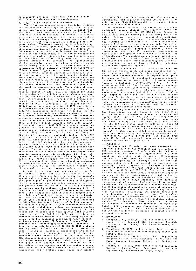
FS~=( FR, SB,OB,S, K ) ( 1 ) where:FB-functional knowledge blocks, the most important for this ES model being those related to different recognition classes, SB-structural blocks representing the knowledge and relations in the system of hierarchy, OB-operation knowledge block b y which conclusion strategy is established,S- coupling function by which knowledge acquisition model is achieved, and K-composition function by which the reasoning model in the knowledge base of this ES is established. The entities of declarative and heuristic knowledge for the maintenance planner are represented through the structure of facts and rules in Fig.3.
The established model of the functional knowledge structure is the basi., for finding corresponding language with grammar, and l o r the construction of automata [ 1 2 , 1 3 ] , so that the knowledge transfor- mation has the form:
FS-G-A ( 2 ) where:L(G)-the language by which the transformation of function knowledge structure (FS) into suitable grammar ( G ) is achieved, and A-automaton correspond- ing to the selected language and the corresponding grammar.
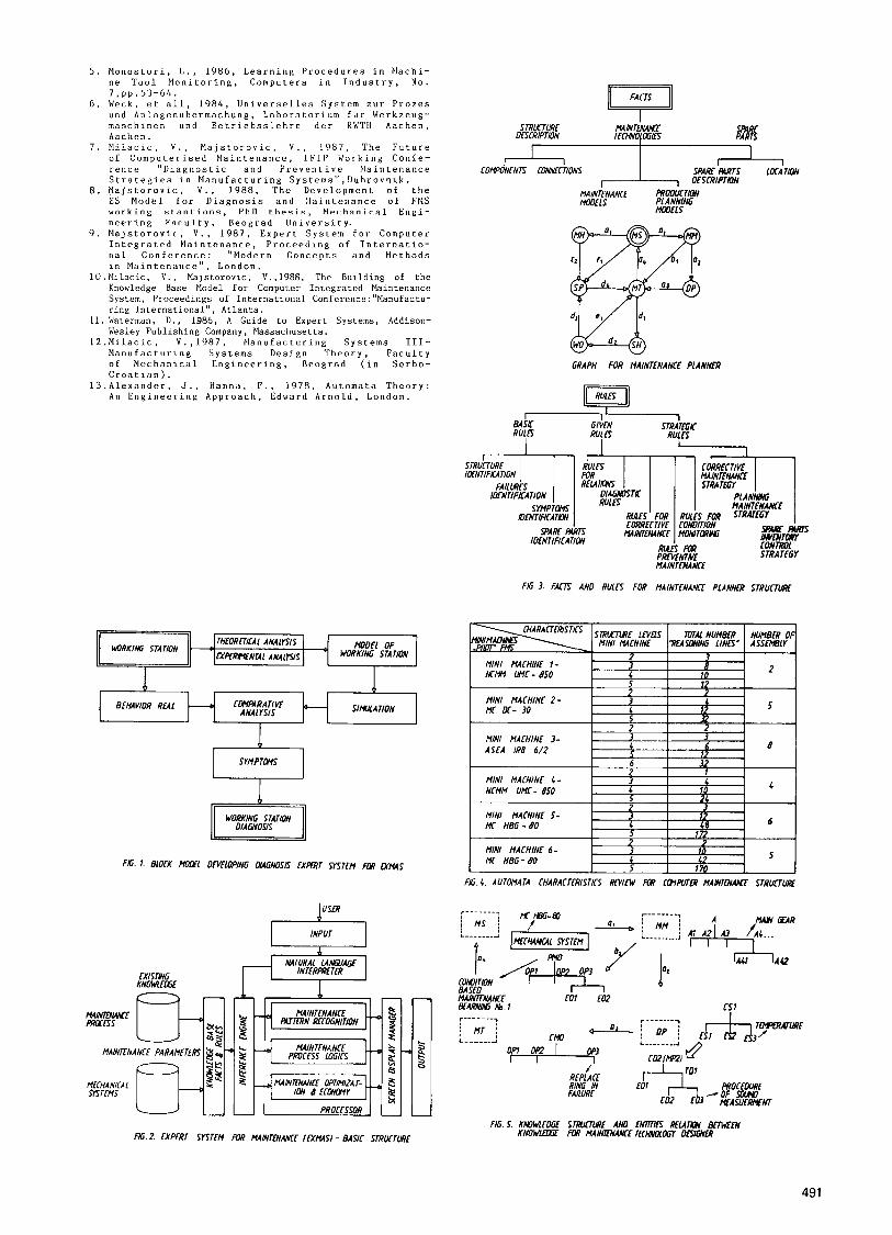
In this expert system the engineering logic is automata-modelled, but oriented to engineering logic with some empiric contents also. The following situations in the diagnosis and maintenance are modelled with automat0n:maintenance structure;rela- tions: symptoms-diagnoses, re1ations:diagnostic con- clusions-maintenance technology,etc. This has been achieved with nondeterminate automaton in the form of a quintuple (input.starting state, transfer function, states and tinal state). With linking o f executivii rules the chains are defined for the knowledge acqui- sition and inference line. F i g . 4 shows summarised analysis of results obtained with the software support for automata, maintenance computer structures and selected mini machines in the “pilot“ FMS model. The large number of reasoning lines from 1 2 to 1 7 2 is
Annals of the ClRP Vol. 38/1/1989
particularly stressed. They enable the realisation of different inference engine conclusions.
3 . EXMAS - SOME RESULTS OF EXPERIMENTS The relations between certain knowledge entities
for maintenance technology designer, i.e. a psrt of the maintenance planner, relating to maintenance planning of work stations are shown in Fig.5. F o n - terminate symbol M M represents different work station maintenance structures, and the facts representing declarative knowledge. The structure and connections for a given mechanical system are idenLified with the basic rules. Terminate symbol a is defined as:a = (elements, features. quantity), 'and the followiAg operations are carried out over this knnw1Pdgr:a = (decomposition,coupling).The decomposition operahicns relate to the establishlng of the entire maintenance structure of work station,and the coupling is carried out according L O relationship relations in main- tenance structure in question. The formalisaLion of this knowledge is made according to the rules with the following form: STRUCTURE COMPONENTS: : =ELENENT (e1ement)IS-PART-OF(e1ement);STRUCTUKE CONNECTIONS::= E L E I I I E N T ( e l e m e n t ) I S _ A T O E l ( a t o m ) . These three groups of rules in PROLOG notation describe all possible forms of the structure of the work station,including: hierarchical structural elements, connections and its last element. O n the basis of similar hypotheses the definition and the formalisation of the knowledge for other nonterminate and terminate symbols of Lhe graph in question are made. The problem of sche- duling of planned maintenance in WRP production control concept in FNS. Fig.3. is complex,for which the question of priorities between planned and cor- rective maintenance has to be solved. In (81 detailed model is presented. Here characteristic examples are quoted for the group of strategic rules, The first example is:RULE 4 (Priotity 2 for failure removal); IF failure at work station prioty 2 THEN apply Rule 4 on planned maintenance operations with probability of 0 . 8 . The maintenance technology scheduling f o r FMS work stations is made according to three criteria: maintenance operations, maintenance work orders and mechanical system to be maintained. The strategic rules for scheduled maintenance operations are classi- fied into five groups. Example: RULE 2,IF priority 1 (certainty factor - 0 . 8 ) THEN maintenance operations planned for the most suitable production terms. Scheduling of maintenance repair orders is carried out according to criteria for 9 priorities. Example: RULE 3 ; IF priority 2 (certainty factor - 0 . 8 ) THEN carry out work orders with the highest downtime costs per unit of time. The third group o f rules re- lates to the definition of priorities for mechanical systems. There are 5 in all: RULE 1 ; IF priority 0 (certainty factor -0.9) THEF mechanical systems very complex. The failure o n them causes very great damage Translated into the entire logic of this expert SYS- tem, for nonterminate node-scheduling ( S C H ) four line reasoning may be established: PIS+ a7 a2 aJ dl d2 , Y S + a7 bl d7 d2 , MS+ cr c2 d4 d7 dg and EIS + f, d4 d, d2. The first reasoning line relates to scheduling according to maintenance operations, and the third and the fourth according to the maintenance history and the control of spare part stores (maintenance orders)
In the further text the examples of rules for maintenance planner for the work station PIC HBG- 80 are given. First two basic rules for nonterminate symbol -DP are given, Fig.3. MC a s machining station has certain quality parameters relating to the geomet rical, kinematic and operation accuracy, so that the general form of the rule for quality diagnosis parameters may be written in the following form: IF (quality function)(parameters)THEN(examination proce- dure). The example is: RULE 18 (quality diagnosis);IF parallelity of machined surfaces A and B in housing No.016845 is under 0.025 mm THEN establish paralleli- ty of main spindle in relation to x-axis according to DIN 8620. For identification o f failure the gene- ral form of the rule is: IF (failure-occurrenc e ) T H E N (place.with probability pi)and the example is:RULE 2 8 ; IF after completion o f machining cycle tool holder not released from main spindle THEN evidence
of VIBRATIONS, and (iii)Lhere exist rules with word TEMPERATURE THEN suggested evident (0.75) that rules relating t o VIBRA'PIONS should be executed before rules with word TEMPERATURE.
The presented ES model was tested at the above mentioned working station. The knowledge base for the diagnostic system for ZIC HBG-80 was formed in PROLOG notation by forming the following facts and rules: failure occurrence probability, symptoms, definition of connections: diagnosis(e)-symptom ( u ) ~ element (u)-technology(ej of corrective mainte- nance and element (u)-spare part (parts). The chain- ing in the knowledge base is achieved with the use of PROLOG features, backward retrieval, when in interactive dialogue, ES answers, corresponding facts about the symptom are entered for the chaining of hypotheses. The conclusions are drawn via certain- t y factor, calculated with Bayes formula.Conflicting situations are solved with selectivity coefficients, representing the sum of Bays probability relations o i the e v e n t : s y m p t o m - d i a g n o s i s .
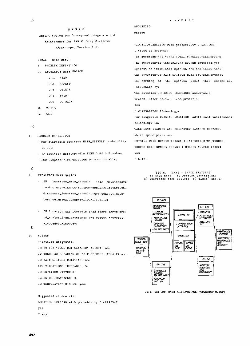
I n order to check the basic features of developed ES, it was tested o n 39 different examples for the above mentioned MC. The folowing results were ob- tained f r o m answers received and explanations given by reasoning lines: (i) absolutely accurate answers: 10 test examples o r about 25X; (ii) exact answers (answer reliability interval:0.9-0.6), 1 7 test examples o r 4 5 % ; (iii)partly exact ansuers.requiring additional analyses (reliability interval:0.4-0.6). 8 test examples, o r about 20%; and (iv) wrong o r unsatisfactory answers (reliability interval 0.4). 4 test examples, o r about 12%. I n Fig.6 the outcome o f this LS is shown o n : a) main menu, b)problem definition, c)knowledge base editor, and d)ES answer with the reasoning line explanation. Given answer relates to conceptual diagnosis and maintenance, as well a s to required spare parts.
For working station MC DC-30 the knowledge base has been formed o n the basis of the translation of the existing diagnostic system into facts and rules, while for IRB 6/2 ASEA the formalisation of electronic errors in Lhe knowledge base rules was made. Finally, the knowledge base was formed for UMC-850 contajning quality indices of this ME1 (kinematic accuracy, measuring uncertainty, geometri- cal accuracy of axes and Lhe measuring of etalon pieces). In this example EXNAS is used as ES consul- tant for establishing of checking procedures for corresponding quality parameters. The output from this ES for all described examples with detailed comment of results i s given in [ a ] .
4 . CONCLUSlON The described ES model has been developed for
off-line approach to the diagnosis and maintenance of FMS working stations, Fig.7, with the following possibilities of industrial application: (i) this model may be applied with the use of PC computers for certain work stations, (ii) with installing of a corresponding A1 language into the computer control unit, it will be possible to translate the existing diagnostic system into the expert diagnostic system according to the EXXAS model, as it has been done for MC DC-30 and IRB 612. The future research o n this ES will include: (i)the research and improve- ment of ES basic features,such as: (a)testing of established concept of the knowledge base and infe- rence engine on a large computer, with different languages and A1 tools, (b)the research of optimal models for the representation of different knowledge, and in particular of cognitive process of maintenance engineers, (c)the research of inference engine model with distributed reasoning, and (d)the development of a learning model, orinted to specific problems in diagnosis and maintenance of divergent FMS work stations, and (ii)the research of problems relating to the ES environment, these being: (a)occurrences and diagnostic processes o n different FMS work sta- tions, (b)CIM concept, the place, the role and the integration of ES with the software for this concept, and (c) the development of models of adaptible expert . . aiagnostic systems suggested with probability 0 . i 5 .that failure o n
~~
lead-out valve of pneumatics of tool clamping system. Given rules for condition based maintenance technolo- gy have a common form: IF (machine element) THEN (maintenance technology)(parameters). Example: IF front main spindle bearing of MC HBG-80 THEN exchange bearing when: (i)vibration amplitude at measuring site 1 during two successive mesurements 0 . 0 8 mm and (ii)temperature at measuring site 1 during two successive measurements 85'C. The relations between FMS characteristics are defined with strategic rules applied maintenance technology models, and procedures for spare part storage control. Example o f rule for selection and application of diagnostic procedu- res: RULE 5 ; IF (i)main spindle o n condition based maintenance and (ii)there exist rules with mention
5. REFERENCES 1 . Kobayashi. K., Inaba,S.,1985, The Practical App-
roach to an Unmanned FMS Operation, Flexible Automation in Japan, IFS (publications),Ltd., Bedford.
2. Yoshikawa, H.,1977, A Preliminary Study of Diag- nosis and Elaintenance o f ?lanufacturing Systems,NTH SINTEF, Trondheim.
3. Shahinpoor, PI., Vells, D., 1986, Engineering Diagnostics and Troublesl~ooting: A New Use f o r Fuzzy Logics, Clarkson College of Technology, Post dam.
4 . Takata, S . , et all, 1985, Monitoring and Diagnosis System of Machine Tools, Department of Precision Engineering, UniversiLy of Tokyo, Tokyo.
5 . M o n o s t o r i , L . , 1986, L e a r n i n g P r o c e d u r e s i n M a c h i - n e T o o l N o n i t o r i n g , C o m p u t e r s i n I n d u s t r y , No. 7 , p p . 5 3 - 6 4 .
6 . W e c k , e t a l l , 1984 , U n i v e r s e l l e s S y s t e m z u r P r o z e s u n d A n l a g e n u b e r m a c h u n g , L a b o r a t o r i u m f u r W e r k z e u g - m a s c h i n e n u n d B e t r i e b s s l e h r e d e r RWTH A a c h e n , A a c h e n .
7 . M i . l a c i . c , V . , P l a j s t o r o v i c , V . , 1 9 8 7 , T h e F u t u r e o f C o m p u t e r i s e d M a i n t e n a n c e , I F I P W o r k i n g C o n f e - r e n c e " D i a g n o s t i c a n d P r e v e n t i v e M a i n t e n a n c e S t r a t e g i e s i n M a n u f a c t u r i n g S y s t e m s " , D u b r o v n i k .
8 . M a j s t o r o v i c , V . . 1 9 8 8 , T h e D e v e l o p m e n L o f t h e &S M o d e l f o r D i a g n o s i s a n d : . l a i n L e n a n c e o f FMS w o r k i n g s t a n t i n n n . P h D t h e s i s , E l e r h n n i r n l E n g i - n e e r i n g F a c u l t y , B e o g r a d U n i v e r s i t y .
9 . M a j s t o r o v i c . V . , 1 9 8 7 , E x p e r t S y s t e m f o r C o m p u t e r I n t eg r a t e d P r o c e e d i n 8 o f I n t e r n a t i o- n a l C o n f e r e n c e : " E l o d e r n C o n c e p t s a n d M e t h o d s i n M a i n t e n a n c e " , L o n d o n .
l O . N i l a c i c , V . , P l a j s t o r o v i c , V . , 1 9 8 8 , T h e B u i l d i n g o f t h e K n o u l e d g e B a s e Model f o r C o m p u t e r I n t e g r a t e d M a i n t e n a n c e S y s t e m , P r o c e e d i n g s of I n t e r n a t i o n a l C o n f e r e n c e : " H a n u f a c t u - r i n g I n t e r n a t i o n a l " , A t l a n t a .
1 1 . Waterman, D . , 1 9 8 6 , A G u i d e t o E x p e r t S y s t e m s , A d d i s o n - W e s l e y P u b l i s h i n g Company, E l a s s a c h u s e t t s .
l Z . H i l a c i c , V . , 1 9 8 7 , M a n u f a c t u r i n g S y s t e m s I I I - M a n u f a c t u r i n g S y s t e m s D e s i g n T h e o r y , F a c u l t y o f M e c h a n i c a l E n g i n e e r j n g , B e o g r a d ( i n S e r b o - C r o a t i a n ) .
1 3 . A l e x a n d e r , J . , H a n n a , F . . 1 9 7 8 , A u t o m a t a T h e o r y : An E n g i n e e r i n g A p p r o a c h , E d w a r d A r n o l d , L o n d o n .
M a i n t e 11 a n c e ,
MINI MACHINE 3- ASEA IR8 6 / 2
MOOEL OF THEORt7lCAL ANALYSIS I EXPtRrrCNTAl ANAllYS WORKING STA TlON
I I 3
12 4 4 - 8
6 32 4
SMLATION CLWFARATIVF ANALYSIS
MINI MACHINE 4 - I NCMM UMC- 850
FG. 1. BWCK MOM OWELOPING DUGNOSK EXmT SYSTEM Mp
I USCR
I I 1 4
4 10 _ .
I INPUT -1
2
4 2
4 5
MINI MACHINE 5- MC HBG - eo
MC HBG - eo MINI MACHINE 6-
INTfRFWTER
3
172
10
170
48 < 6
(2 S
I I
F& STRUURE DESCRIPTION TEChWOl OGIK -
SPARE M T S LOCATION OESCRIPTON
- COMPONENTS CDNNCT~ONS
MAINkNANCE mOOuCTION MODELS P1 ANNING
M r n m
GRAPH FOR MAIMENANCE PLANNER
I ~1 a4iu GIVEN STRAKGK RU(ES RULES RU1 fS
I I r
Fffi.3 FACTS AN0 RULCS FOR UAINTENANCE PLANNCR STRUCTUM
J 3 6
10 5 12
MINI MACHINE 1- - 2 NCMV mc- eso 7
4 12 t 3 I MINI MACHINE 2- I MC DC- 30
FIG. 4. AUTOMATA CHARACTERISTICS WITW
FIG.2. EXPERT SYSTfM R)R MAINTtNMCE It-k'MSI - BASIC STRUCTURE
49 1
a) C O M M E N T
E X M A S
Expert System for Conceptual Diagnosis and
Maintenance for FMS Working Stations
(Prototype. Version 1.0)
EXMAS - MAIN WNU:
1. PROBLEM D6FINITION
2. KNOWLEDGE BASE EDITOR
2 . 1. READ
2.2. APPEND
2.3. DELETE
2 . 4 . PRINT
2.5. GO BACK
3. ACTION
4. EXIT
b)
SUGGESTED
choice
-LOCATION-BEARING-with probability 0.422YO547
I think so because:
The question-ARE-VIRRATIONS_INCREASED-answered:5,
Thc que.stion- IS-TEMPERATURE-HIGHER-answered: yes
Against so formulated opinion are the facts that:
The question- IS-MAIN-SPINDLEPROTATINf;-answered: no
The forming of the opinion about this choice not
influenced by:
The question-IS-NOISE-INCREASED-answered:O
Remark: Other choices less probable.
Yes
?-ma1 ntenance-techno1 ogy . For diagnosis BEARING-LOCATION additional maintenance
technology is:
TAKE_DOWN-BEARING-ANDEXCHANGBD_DAMAC;ED-DAMAGED-ELEMENT,
1 , PROEiLEM DEFINITION while spare parts are:
- For diagnosis position MAIN-SPINDLE probability OUTSIDE~RING-NUM~ERPlOOOOl-*~INTERNAL~RING~NIJMBER~
is 0.1; 1 0 0 0 0 2 ~ B A L L ~ N U M B E R ~ 1 O O O O ~ ~ i ~ H O L D E R ~ N U M B E R ~ l O O O O 4
- IF position main-spindle THEN 0.92 0.3 noise; yes
- FOR symptom-VIBR question is considerable; ?-halt.
4
2. KNOWLEDGE BASE EDITOR FIG.6. EXMAS - B A S I C FEATURES
a) Main Menu; b ) Problem Definition; c ) Knowledge Base Editor; d) E X M A S ' answer
- IF locat ion-main-spindle THEN maintenance
d )
3 .
technology:diagnostic-programs_SJ37-e~8tabli~h
diagnosis-fiinction-spindle-then-consult-main-
tenance-mnual-chapter-lO-*-l1_i-12;
- IF location-main-spindle THEN spare parts are:
id-number-fro~catalogue_r/d_045604_+-600504-
i-5006500-*-500069;
ACT I ON
?-execute-diagnosic.
IS_BlJTTON-" TOOL-NOT-CLAMPED"-AI. IGHT: no.
I S ~ T H E R E ~ N O ~ C L E A N I N G O F _ M A I N _ S P I " O _ A I R ~ : n o .
IS-MAIN-SPINDLE-ROTATING: no.
ARE-VIBRATIONS-INCREASED: 5.
IS-ROTATION-UBBVEN: 0.
IS-NOISE-INCREASED: 0 .
IS-TEMPERATURE-HIGHER: yes.
-1NTiR FACi CNC CU
1-1 -0MGNOSK
TiCHWLOoI
!I
Suggested choice (i):
LOCATION-BEARING with probability 0.422'30547
yes
?-why.
492