Embed Size (px)
Citation preview
EEE TRANSACTIONS ON MAGNETICS, VOL. 28, N0.2, MARCH 1992 1763
An Expert System for Preliminary Design of Contactors
A. Gentilhomme, J. Bigeon,J.L. Coulomb Laboratoire d6lectrotechnique de Grenoble (U.A. 355 CNRS)
ENSIEG Domaine Universitaire,B.P, 46 38402 St Martin d'Heres Cedex
FRANCE Abstmct:The authors present in this paper an expert system for the design of contactors. This system couples preliminary design using heuristic rules and electromagnetic analysis based on the equivalence of electric and magnetic circuits. The expert system presented in the following sections takes easily into account the preliminary design process and has been achieved with a high interactivity level. It uses a blackboard architecture to manage and control the knowledge of the whole system. This approach has given good results with respect to the integration of various knowledge models used.
M. Lauraire T6l6m6canique
33bis AV. du Markha1 Joffre 92000 Nanterre
FRANCE
I. INTRODUCTION
The role of contactors, which are often used to control electrical machines, is to establish, support and switch off current in one or more electrical circuits by means of separable contacts. An electro-magnet is used to supply the energy required for opening and closing operations. In addition, springs allow the contactor to come back to its neutral position when the supply current is switched off. The expert system presented in this paper allows the determination of the different components of contactors, for example springs, contacts, electro-magnet's geometry and the coil. Its handles various types of knowledge like heuristic rules and numerical and analytical computations. Some manufacturing constraints are taken into account for computing physical values requested from an electromagnetic point of view. After a short presentation of the characteric values used in the preliminary design of contactors we inaoduce the specific features of the preliminary computed aided design of such devices.
In this paper we will develop below the relationships between the design problem and the expert system aids. We will propose a knowledge model which is able to take into account the differents aspects presented. Finally we will present the whole system which has been implemented and is used in an industrial environment.
I1 DESCRETION OF CONTACTORS
Contactors have an essential place in the field of electrical devices. They are used each time when insulation between the control and power parts is needed. The general principle is very simple. Fig. 1 enables the reader to understand better the functional behaviour of contactors.
Manuscript received July 7,1991
A'. removable auxiliary contacts B.terminals C.fixed contacts D. arc box E. base F.phaser ring G-fixed magnetic circuit H . hook J.shock absorber K.coil L. springs %mobile magnetic circuit N.mobile contacts P.pole's springs
Fig. 1 : General overview of a contactor When the current in the coil (K) is switched on the mobile
part of the electromagnet (M) is attracted by the fied part of the electromagnet.The mobile part is linked with the mobile contacts (N). When they touch the fixed contacts (C) the power current is established. When the current is switched off in the coil the return's spring pushes back the mobile part which opens the contacts. The contactor is back to its normal state. The main parts of this apparatus are
-contacts -pole 's springs -diagram forces versus air-gap size (see fig. 2) -characteristics of the electro-magnet -dynamical behaviour of contactors (delay to be closed or
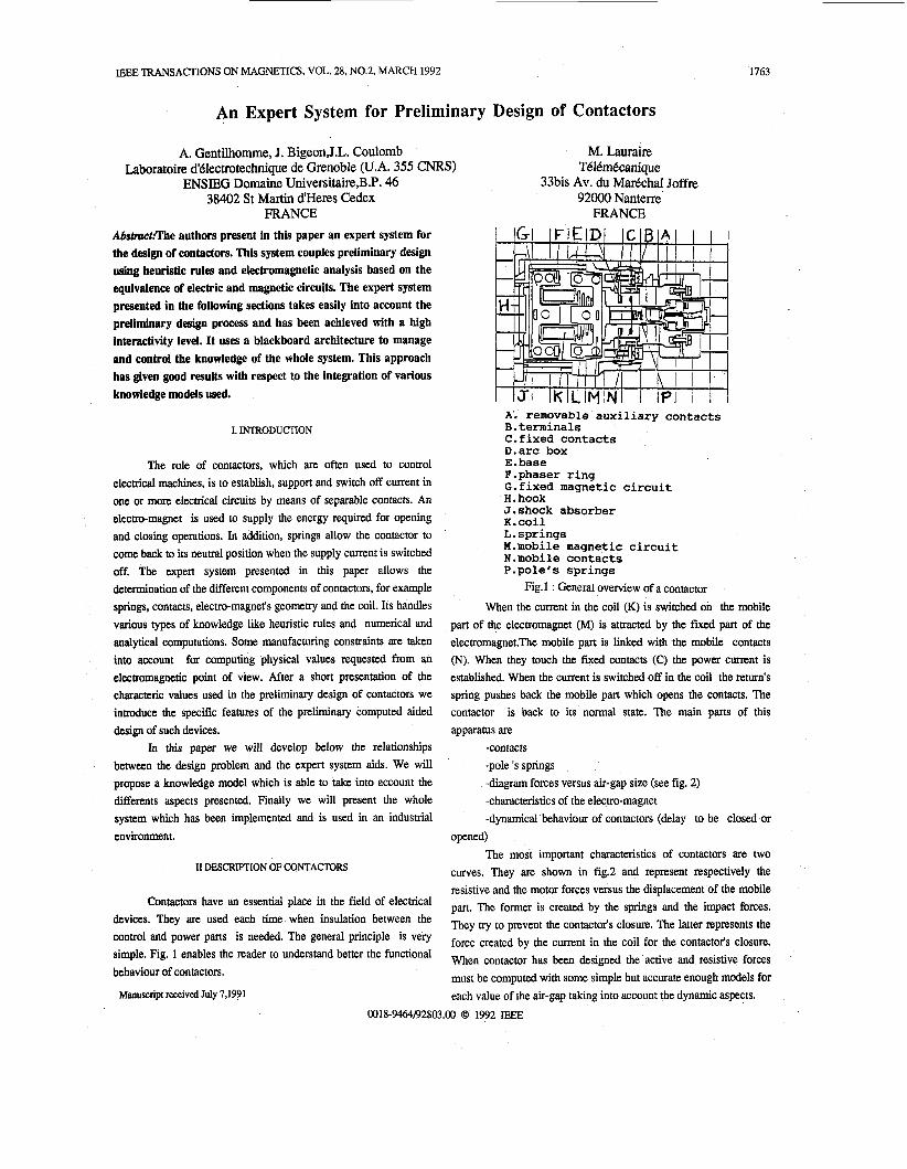
opened) The most important characteristics of contactors are two
curves. They are shown in fig2 and represent respectively the resistive and the motor forces versus the displacement of the mobile part. The former is created by the springs and the impact forces. They try to prevent the contactor's closure. The latter represents the force created by the current in the coil for the contactor's closure. When contactor has been designed the active and resistive forces must be computed with some simple but accurate enough models for each value of the air-gap taking into account the dynamic aspects.
0018-9464/92$03.00 0 1992 IEEE
1764
Resistive forces B. Unification of the heuristic and computational treament
poles springs action
air - gap Fig.2 Resistive forces versus air-gap
IILDESIGN PROBLEM
As mentioned by many authors [3],[4],[5] the design process is difficult to model.Today powerful CAD/CAM systems provide engineers with very fine analysis tools. But these tools have mainly two drawbacks. First, their computational cost increases with the complexity of the tools and second there is a need to have a clear idea of what is fed into these programs (geometrical dimensions, material used .....). These tools need on input what is called the preliminary design of the device.In order to get the preliminary design engineers have to deal with many different knowledge sources. In general, and it is also true in the field of contactors, these sources are mainly of three kinds:
-scientific knowledge -manufacturing constraints -industrial environment According to the specifications the engineers propose some
contactors which fulfill the initial specifications. In fact they often have no more than two or three preliminary designs because it is not easy to do more than three times. This is the preliminary design task. At this stage the engineers try to use all their expertise.Using this design approach we will focus on the preliminary design process for the system's architecture proposal. The methodology proposed above up leads us to develop three major points.
A. hypotheses and parallel solutions
The methodology used leads us to build a system which must be able to deal with hypotheses. During the preliminary design process we need to make choices. In some particular cases we will not be able to decide between two differents rules (heuristic or computational). So we will make two hypotheses and continue to proceed with these different assumptions which lead us to have more than one potential solution. FurthermoE some rules entail a multiple values of the same parameter (for example when a rule takes values from tables for a geometrical parameter like the height of the electromagnet). For these reasons a good preliminary design must be able to manage all these "instances" of the contactor.
In fact the knowledge used in the electrical engineering field is evolutionary: some rules are actually heuristic but can be replaced in the future by some programs derived from new models.This has to be taken into account in a preliminary design system.
C. User's constraints
A good preliminary design must be able to integrate user- specific constraints (if possible any user-specific constraints). In the future customers may be expected to need more and more specific products but with no additianal charge. The time taken to integrate the new specification must be as short as possible to stay competitive with other manufacturers. This point is from our point of view the most difficult to be integrated into modem computer aided design systems.
111. EXPERT SYSTEM APPROACH AND DESIGN PROBLEM
The three previously explained points show clearly the difficulties in applying classical approaches because of the polymorphism of knowledge, its evolutionary features and user- specific constraints only given at run time.To be closed to the preliminary design, we proposed to distinguish between:
- facts (data) -deductive knowledge (rules) -strategy (how to use the rules)
IV.THE KNOWLEDGE MODEL AND THE! STRATEGY
We present here mainly: -the knoledge model we have proposed and used for facts and rules representation -the control architecture of the system which used blackboard concepts [ 131
All is represented using Object Oriented Representation [6], [7] in the system we have developped because of it power.
A. Facts and decomposability
This database contains all the physical data used i.e. the parameters which describe completely the contactor to be designed. For instance: -the type of matirial of the springs, of the coil and of the contacts -the current in the coil, the voltage of the same coil, the induction in the air-gap of the electromagnet ...
As the number of parameters is very important the human mind not have a global idea of the object to be designed. So it decomposes the whole problem into independant sub-problems. This is done recursively. This important (and not completly me) assumption is often called "hypothesis of design problem
decomposability". A number of people have used this assumption [8], [9], [lo]. We hold that this assumption is not true for the design process of solving because some sub-problems are linked together. These links convey some functionalities or dependencies relationships.
Even this hypothesis is not true a quite decomposability can be used and must be used coupled with dependencies to structure data.
B. Deductive knowledge
As we need to have an evolving system from the knowledge point of view we suggest having the same representation for heuristic rules, tables, formulas and numerical programs. We have choosen the fist order rules formalism for this [71,[131. This formalism allow us to take into account all the type of knowledge we have encountered.
C. Control and blackboard architecture
In a fist approach, we have chosen an inference motor based on the forward chaining method. Using the initial data provided by the user, the inference motor f i i s all applicable rules and try to design the contactor. At the end of the process you will get some instances of contactors that satisfied the preliminary design requirements. These contactors have to be analysed with very fine analysis tools (like FEM, BEM, finite differences). These tools are able to decide which the best product is. This methodology is easy to manage but reveals a high level of difficulties for taking into account user-specific constraints. Morever, in this case the evolution of the expert systems is not easier to manage than big programs in Fortran. If we want to add some knowledge to the system we must have a precise idea of the overall process of design and of the rules in the system. For avoiding this disadvantage we have proposed a blackboard architecture. On the blackboard arrive some events (new values, value's modification...). When an event arrives each knowledge based source (KBS and SdC in French) mes to see if it can do anything for solving a part of the problem of design. All KBSs applicable are put into an agenda. At this stage the control function decides which KBS has to be f i d . This is repeated until there is no more KBS to be applied. This approach provides two main advantages. First the knowledge of the domain is more separate from the way of solving the problem (solving strategy). Second there is a unified way of exchanging data between experts: "the blackboard". Rules do not interact directly, they interact via data on the blackboard. We suggest taking as events the modification of the parameters, and objects creation and destruction. We define KBS as boxes with three parts: The fist part is a rule in which we put the condition to fire the KBS. It is called the condition part. The second constitutes the rules belonging to the KBS. The last part is the problem's contibution.
1765
V. SYSTEM BEHAVIOUR
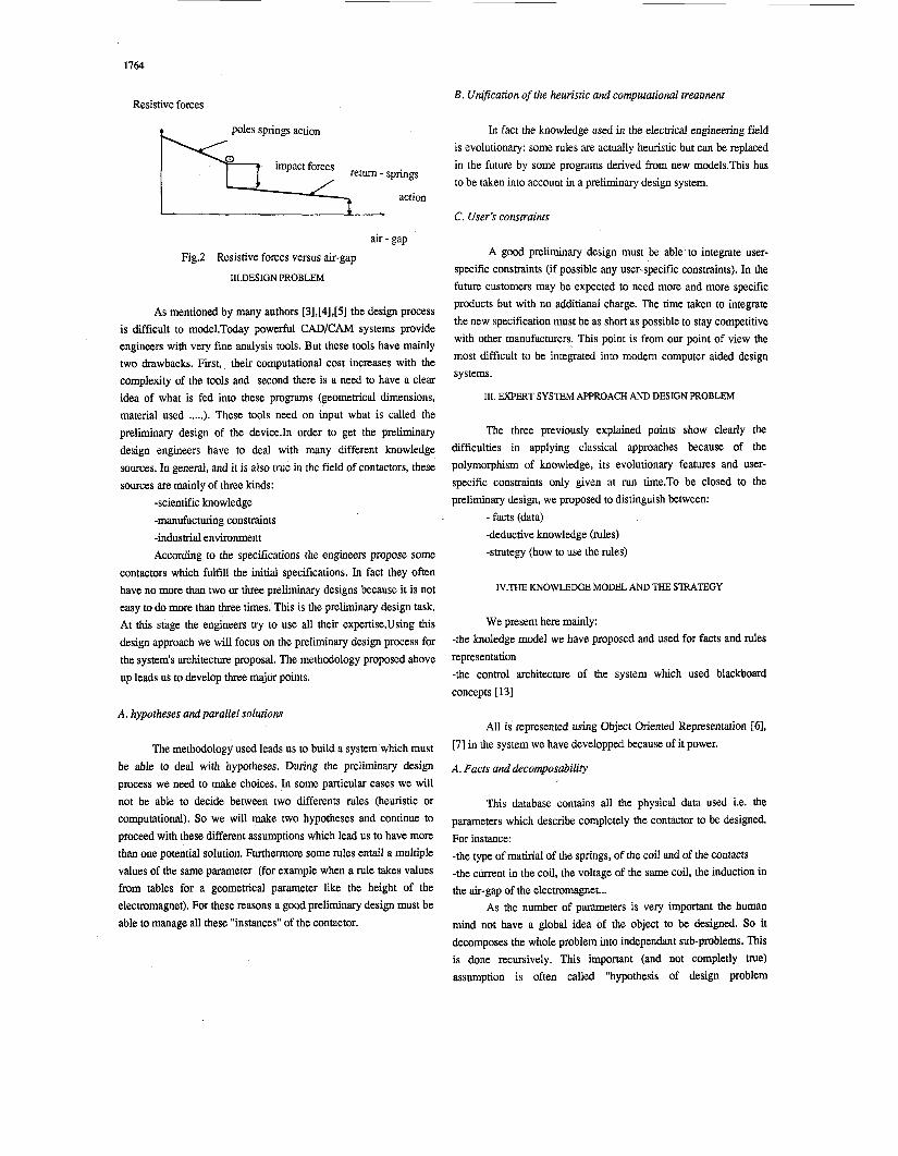
We will show some possibilities for our system. Fist of all, a screen appear into which the user can interactively (using the keyboard or mouse) define the initial data (see fig.3)
c - N m r =ma
Fig.3 specification of the initial datas After the first screen has been validated, a second screen
appears in which an engineer can impose my values he want (%e
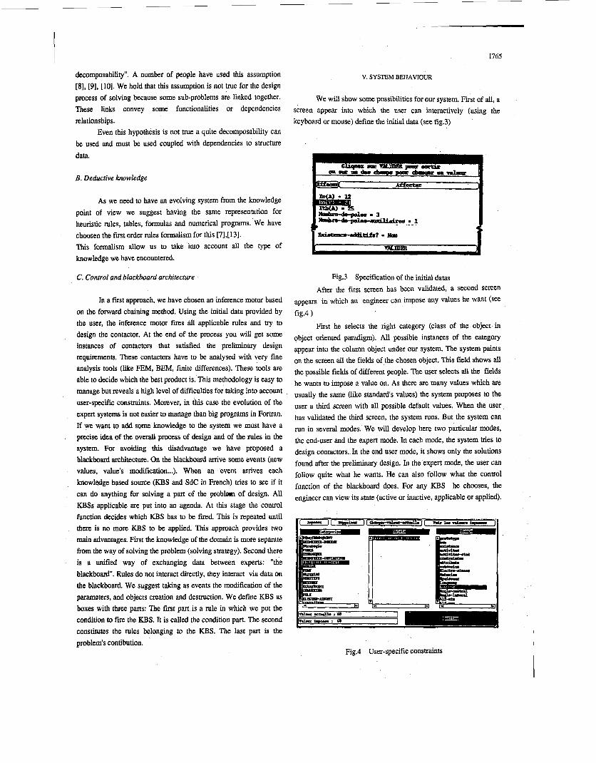
First he selects the right category (class of the object in object oriented paradigm). All possible instances of the category appear into the column object under our system. The system paints on the screen all the fields of the chosen object. This field shows all the possible fields of different people. The user selects all the fields he wants to impose a value on. As there are many values which are usually the same (like standards values) the system proposes to the user a third screen with all possible default values. When the user has validated the third screen, the system runs. But the system can run in several modes. We will develop here two particular modes, the end-user and the expert mode. In each mode, the system tries to design contactors. In the end user mode, it shows only the solutions found after the preliminary design. In the expert mode, the user can follow quite what he wants. He can also follow what the control function of the blackboard does. For any KBS he chooses, the engineer can view its state (active or inactive, applicable or applied).
fig4 )
PI.*- .. 1 I
Fig.4 User-specific constraints
1766
He can also have dynamically the construction of any instances of developed a based on the graphical windowed contactor during the preliminary design process* That interesting because our proposed system manages parallel (see fig.5)
be interface ADA. It allows the user to give specifications and View the results under the form of representative curves and schemaas. In the expert mode, the user can dynamically follow the solution that
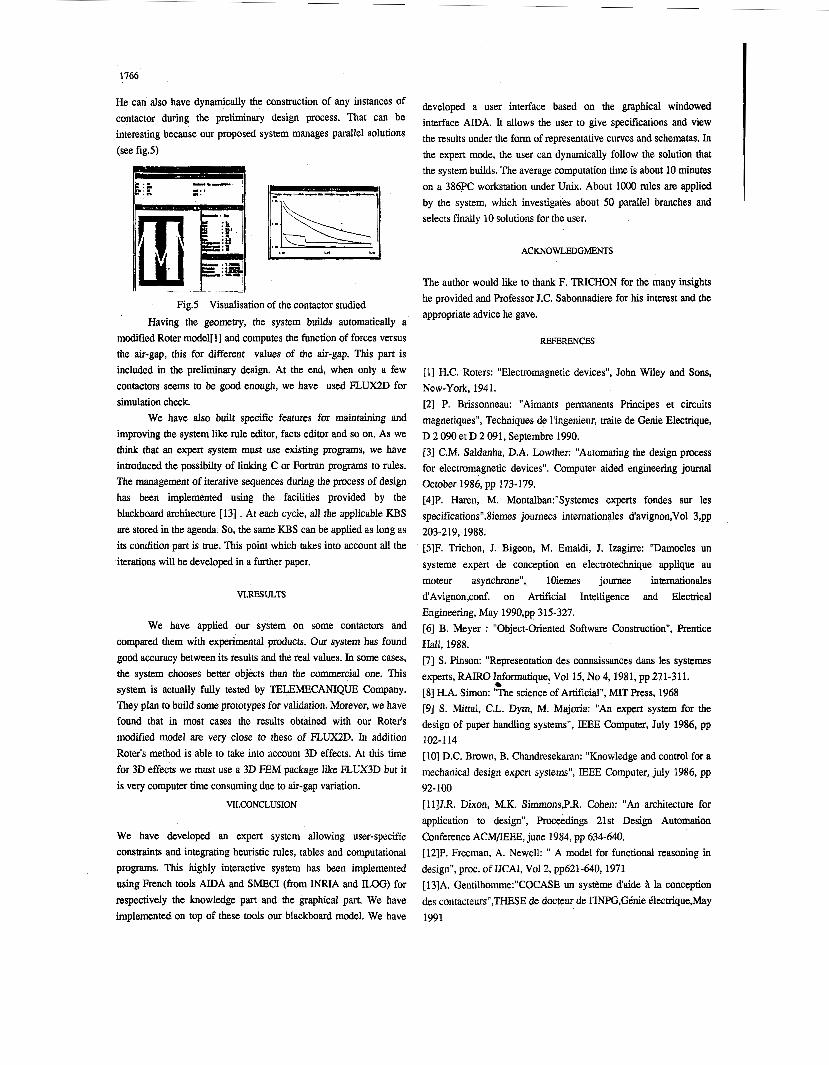
Fig.5 Visualisation of the contactor studied Having the geometry, the system builds automatically
the system builds. The average computation time is about 10 minutes on a 386PC workstation under Unix. About lo00 rules are applied by the system, which investigates about 50 parallel branches and selects finally 10 solutions for the user.
ACKNOWLEDGMENTS
The author would like to thank F. TRICHON for the many insights he provided and Professor J.C. Sabonnadiere for his interest and the appropriate advice he gave.
a modified Roter model[ 13 and computes the function of forces versus the air-gap, this for different values of the air-gap. This part is included in the preliminary design. At the end, when only a few contactors seems to be good enough, we have used FUJX2D for simulation check.
We have also built specific features for maintaining and improving the system like rule editor, facts editor and so on. As we think that an expert system must use existing programs, we have introduced the possibilty of linking C or Fortran programs to rules. The management of iterative sequences during the process of design has been implemented using the facilities provided by the blackboard architecture [13] . At each cycle, all the applicable KBS are stored in the agenda. So, the same KBS can be applied as long as its condition part is true. This point which takes into account all the iterations will be developed in a further paper.
VLRESULTS
We have applied our system on some contactors and compared them with experimental products. Our system has found good accuracy between its results and the real values. In some cases, the system chooses better objects than the commercial one. This system is actually fully tested by TELEMECANIQUE Company. They plan to build some prototypes for validation. Morever, we have found that in most cases the results obtained with our Roter's modified model are very close to these of FLUX2D. In addition Roter's method is able to take into account 3D effects. At this time for 3D effects we must use a 3D FEM package like FLUX3D but it is very computer time consuming due to air-gap variation.
VILCONCLUSION
We have developed an expert system allowing user-specific constraints and integrating heuristic rules, tables and computational programs. This highly interactive system has been implemented using French tools ADA and SMECI (from INRIA and LOG) for respectively the knowledge part and the graphical part. We have
REFERENCES
[l] H.C. Roters: "Electromagnetic devices", John Wiley and Sons, New-York, 1941. [2] P. Brissonneau: "Aimants permanents Principes et circuits magnetiques", Techniques de l'ingenieur, traite de Genie Electrique, D 2 090 et D 2 091, Septembre 1990. [3] C.M. Saldanha, D.A. Lowther: "Automating the design process for electromagnetic devices". Computer aided engineering journal October 1986, pp 173-179. [4]P. Haren, M. Montalban:"Systemes experts fondes sur les specifications".8iemes joumees intemationales d'aVignon,Vol 3,pp
[5]F. Trichon, J. Bigeon, M. Emaldi, J. Izagirre: "Damocles un systeme expert de conception en electrotechnique applique au moteur asynchrone", loiemes journee intemationales d'Avignon,conf. on Artificial Intelligence and Elecmcal Engineering, May 1990,pp 315-327. [6] B. Meyer : "Object-Oriented Software Construction", Prentice Hall, 1988. [7] S. Pinson: "Representation des connaissances dans les systems experts, RAIRO Informatique? Vol15, No 4,1981, pp 271-311. [8] H.A. Simon: "The science of Artificial", MIT Press, 1968 [9] S. Mittal, C.L. Dym, M. Majoria: "An expert system for the design of paper handling systems", IEEE Computer, July 1986, pp
[lo] D.C. Brown, B. Chandresekaran: "Knowledge and control for a mechanical design expert systems", IEEE Computer, july 1986, pp
[11]J.R. Dixon, M.K. Simmons,P.R. Cohen: "An architecture for application to design", Proceedings 21st Design Automation Conference ACM/IEEE, june 1984, pp 634-640. [12]P. Freeman, A. Newell: " A model for functional reasoning in design", proc. of UCAI, Vol2, pp621-640,1971 [13]A. Genti1homme:"COCASE un systkme d'aide k la conception des contacteurs",THESE de docteur de l'INPG,Ghie klecmque,May
203-219, 1988.
.,
102-1 14
92-100
implemented on top of these tools our blackboard model. We have 1991