Embed Size (px)
Citation preview
IEEE Transactions on Power Apparatus and Systems, Vol. PAS-101, No. 1 January 1982
AN INTEGRATED SOFTWARE SYSTEM FOR POWER SYSTEM OPERATION-CONTROL AND -PLANNING
K. FruhaufBrown Boveri & CieBaden, Switzerland
P. Grafoner, MemberBrown Boveri & Cie
Mannheim, FRG
K. SignerBrown Boveri & CieBaden, Switzerland
Abstract - The paper presents the structure of the
software and the data of an integrated system for use
in power generation and distribution control centres.
The integrated system renders a uniform communication
between operators and system engineers on one hand and
supervisory control, security monitoring and short/me-dium term planning software on the other hand. The pa-
per concentrates on the power application software(PAS) and describes the functions available in diffe-
rent console modes. A classification of PAS modules is
introduced and the external and internal data interfa-
ces are discussed.
INTRODUCTION
The present state of electric power systems is
characterized by a steadily increasing load and diffi-
culties in power system expansion resulting in a de-
creasing safety margin. This fact makes the task of
operators and system engineers more and more difficult.Therefore an optimal support of the control room staff
is a necessity. As the widespread SCADA functions are
not sufficient for this exacting task, power applica-
tion functions are being increasingly implemented.However, the PAS functions have usually been im-
plemented as a separate software system with a substan-tially less comfortable man machine communication than
is available in the SCADA system.The concept of an integrated system presented in
this paper is an answer to this problem.
INTEGRATED SYSTEM
The integrated system has the following character-istics:
(i) uniform man machine communication (MMC) withSCADA and PAS functions
(ii) central data base as interface between the majorsoftware subsystems SCADA, PAS and MMC
(iii) common run time environment including facilitiessuch as synchronization, error handling, test
output etc.
The characteristics (ii) and (iii) simplify the designand implementation and help to achieve a high degree offlexibility, maintainability and expandability of the
system.The first aspect is the crucial one for the user.
In controlling the network, an operator thinks in terms
cf functions related to physical actions in the network,e.g. switching out a circuit breaker. Supported by
software, he should not be pushed to change his mind,e.g. he should not have to run a command handler with
"switch off circuit breaker" as parameter.This requirement has always been fulfilled by
SCADA since from the very beginning it was designed for
use in control centres. PAS, however, was first de-
velopee. for off-line use and only more recently imple-mented in on-line systems. From the system point of
view it is a rather philosophical question, as to whe-
ther a push-button should be labelled "State Estimation"
or "complete the measurement set", but to the operatorthey are quite different; the first is a software mo-
dule/mathematical algorithm, while the second is a
function similar to those found in a SCADA system. An-
other aspect on the same level is the presentation of
the results to the operator - the format must be fami-
liar to him in terms of equipment layout, while compu-
ter oriented lists and tables are more appropriate for
a software engineer. This huge effort for PAS integra-tion is necessary in order to exploit all PAS capabi-lities for network operation.
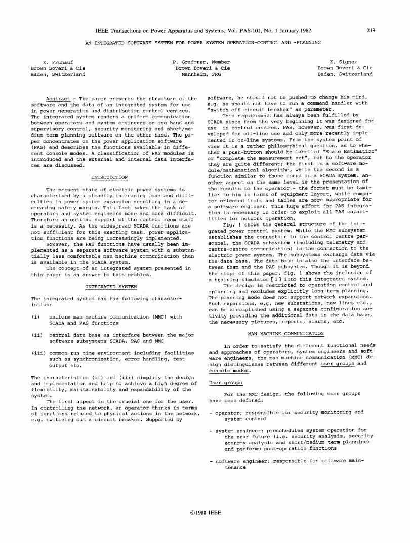
Fig. 1 shows the general structure of the inte-
grated power control system. While the MMC subsystemestablishes the connection to the control centre per-sonnel, the SCADA subsystem (including telemetry and
centre-centre communication) is the connection to the
electric power system. The subsystems exchange data via
the data base. The data base is also the interface be-
tween them and the PAS subsystem. Though it is beyondthe scope of this paper, fig. 1 shows the inclusion of
a training simulator [ 1 into this integrated system.The design is restricted to operation-control and
-planning and excludes explicitly long-term planning.The planning mode does not support network expansions.Such expansions, e.g. new substations, new lines etc.,can be accomplished using a separate configuration ac-
tivity providing the additional data in the data base,the necessary pictures, reports, alarms, etc.
MAN MACHINE COMMUNICATION
In order to satisfy the different functional needs
and approaches of operators, system engineers and soft-
ware engineers, the man machine communication (MMC) de-
sign distinguishes between different user groups andconsole modes.
User groups
For the MMC design, the following user groupshave been defined:
-' operator: responsible for security monitoring and
system control
system engineer: preschedules system-operation for
the near future (i.e. security analysis, securityeconomy analysis and short/medium term planning)and performs post-operation functions
software engineer: responsible for software main-
tenance
1981 IEEE
219
secure energy production and system operation isplanned. The main features of operation planningmode are:
SCADA: functions not available, i.e. control actionsonly affect the network model in the database ("modified data set") but do not lead toactions in the power system.
PAS : - functions run on request- based on actual or modifiednetwork situation
- extensive results available
examples: interactive operator's load flow,load forecast
- training mode
In the training mode, the behaviour of the powersystem and the telemetry system is modelled by atraining simulator (fig. 1 and 4). Within the train-ing mode both operation control and operation plan-ning modes are simulated. The objective of this modeis the training of control room staff.
Design targets
F ,
Tetemetry/ Power System.
Il
The design of the man machine communication hasbeen guided by the following software design targets:
(i) communication with computer is as clear and ef-fective as possible
(ii) data relevant for different user classes arepresented in different console modes and/or indifferent displays and reports
(iii) displays and reports use power system orientedoperating names, symbols and terminology
TSS _ Training Simulator Software MMC - Man-Machine-CommunicationSCADA Supervisory Control and Data AcquisitionPAS ^- Power Application Software
Fig. 1: Integrated Power Control System
Console Modes
Application software can run in different modes.The user can select the following modes per console(working place):
- 2pration control mode
In operation control mdde, system security monitoringand system control are performed. The main featuresof operation control mode are:
SCADA: all functions availablePAS : - functions run cyclically, event driven or on
request- based on actual network situation- results in the form of messages to the oper-
ator
examples: limit check, contingency check, baddata, etc.
operation planning mode
In operation planning mode, economical
(iv) uniform communication with SCADA and PAS func-tions (see also chapt. "Integrated System")
(v) SCADA and PAS software is independent of MMChardware (i/6 devices)
MIC - a software package
The MMC as a software package is defined by twointerfaces (see fig. 1):
(i) the interface to the data base(ii) the interface to the i/o devices (user)
In order to realize the design targets (iv) and (v)there is one common MMC package, which is only con-nected to SCADA and PAS functions via the data base.For "interactive" application software functions, theMMC performs the whole dialogue, while the PAS packageonly executes the appropriate algorithms and storesthe results into the database. From the user's stand-point, the application software is accessed via key-board, VDU and printer in the form of:
- menus : for program/display selection- diagrams: - station diagrams
- nodal diagrams (sections of power sys-tem), see fig. 2
- overview diagrams (eographical voltageprofile, power interchange)
- reports, tabular displays- messages, alarms
220
V[Power Control System
DataBase
r J--I_
but still
221-
tions, in order to analyse the steady state behaviour ofthe system.
The same data set as used for the security analysisclass can also be used for the class of security andeconomy analysis functions. The optimization problem tobe solved is based on spinning generators and switchableelements (e.g. lines, transformers). Both security andeconomic aspects are represented in the objective func-tion.
modifieddata set
secure arcompletedata set
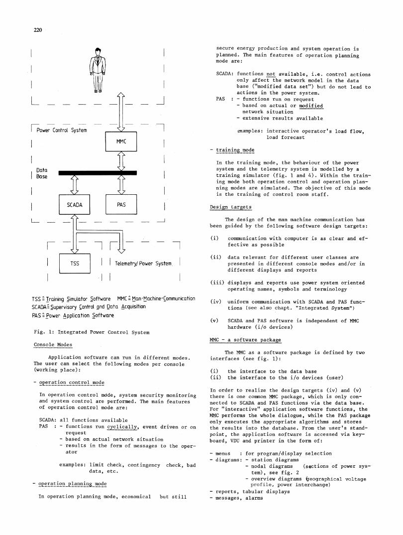
*Fig. 2: nodal diagram - example
In operation control mode, the operator has theoption to display either measured data or calculateddata (state estimation results) on any diagram. The re-sults of power system security checks are presented inthe form of messages to the operator (e.g. messages forelements with exceeded limits in a specified contingen-cy).
In operation planning mode, the system engineer(or operator) has the possibility to modify the networkmodel using station diagrams (e.g. by changing switchstatus) or nodal diagrams (e.g. by taking a transmis-sion line out of service). The results of security ana-lysis or energy management programs are presented incomprehensive form on diagrams and/or reports.
POWER APPLICATION SOFTWARE
PAS classification
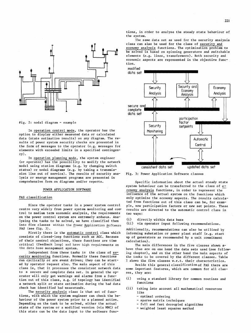
Since the operator tasks in a power system controlcentre vary widely from power system monitoring and corntrol to medium term economic analysis, the requirementson the power control system are extremely arduous. Ana-lysing the tasks to be solved, we have classified theminto five classes within the Power Application SoftwarePAS (see fig. 3).
Firstly there is the automatic control class whichconsists of closed-loop functions such as AGC. Becauseof their control objectives, these functions are timecritical (feedback loop) and have high requirements onthe data base management system.
Independent from these tasks is the class of se-curity monitoring functions. Normally these functionsrun cyclically or are event driven; they can be start-ed by operator request also. The main aspect of thisclass is, that it processes the consistent network datato a secure and complete data set. In general the op-erator will only get warnings and alarms from a func-tion out of this class, e.g. if topology has identifieda network split or state estimation during the bad datacheck has identified bad measurands.
The security analysis class is that set of func-tions, with which the system engineer can check the be-haviour of the power system prior to a planned action.Depending on the task to be solved, either the actualstate of the system or a modified version (via MMC) ofthis state can be the data input to the software func-
Fig. 3: Power Application Software classes
Specific information about the actual steady statesystem behaviour can be transferred to the class of e-conomy analysis functions, in order to represent theinfluence of the actual system on the functions whichonly optimize the economy aspects. The results calcula-ted from functions out of this class can be, for exam-ple, new participation factors or new set points. Theseresults are directed to the automatic control class intwo ways:
(i) directly within data base(ii) via operator input following recommendations.
Additionally, recommendations can also be utilized byinforming substation or power plant staff (e.g. startup of generators as recommended by a unit commitmentcalculation).
The main differences in the five classes shown a-bove thus are on one hand the data sets used (see follow-ing chapter), and on the'other hand the main aspects ofthe tasks to be covered by the different classes. TableI shows the five classes w.r.t. their characteristics.
Beside this general classificationof PAS there aresome important features, which are common for all clas-ses, they are:
(i) using a standard library for common routines andfunctions
(ii) taking into account all mathematical resourceslike- optimal ordering- sparse matrix techniques- full and fast decoupled algorithms- weighted least squares method
222
Table I: PAS classes and their characteristics
Class Characteristics
AUTOMATIC - raw values (measurands, indications, ...)CONTROL - closed loop actions
- results back to "updated data set" (SCADA)- time critical
SECURITY - basis is "consistent data set"MONITORING - creates 'secure and complete data set"
- run cyclic or event driven- start on operator request is possible
SECURITY - basis is "secure and complete data set"ANALYSIS - gives an answer to the main question:
"What happens if?"
SECURITY - basis is "secure and complete data set"AND ECONOMY - optimization w.r.t. active generators andANALYSIS switchable elements (lines, transformers, etc...)
- represents security and economy aspects at a time
ECONOMY - basis is "secure and complete data aet"ANALYSIS - optimization is performed only due to economy
aspects
(iii). running the algorithms parameterized. Possibleparameters are e.g.:- load curve- area generation increase/decrease- area load increase/decrease- fixing/freeing of transformer control
(iv) taking into account all existing power supplyequipment with its physical and operationalrestrictions;e.g!:- real and quadrature transformer control- LTC-transformer- min./max. transformer taps- min./max. real power generation limit- min./max. reactive power generation limit- min./max. voltage limit- remote node voltage control- area controlled interchange
Data structure
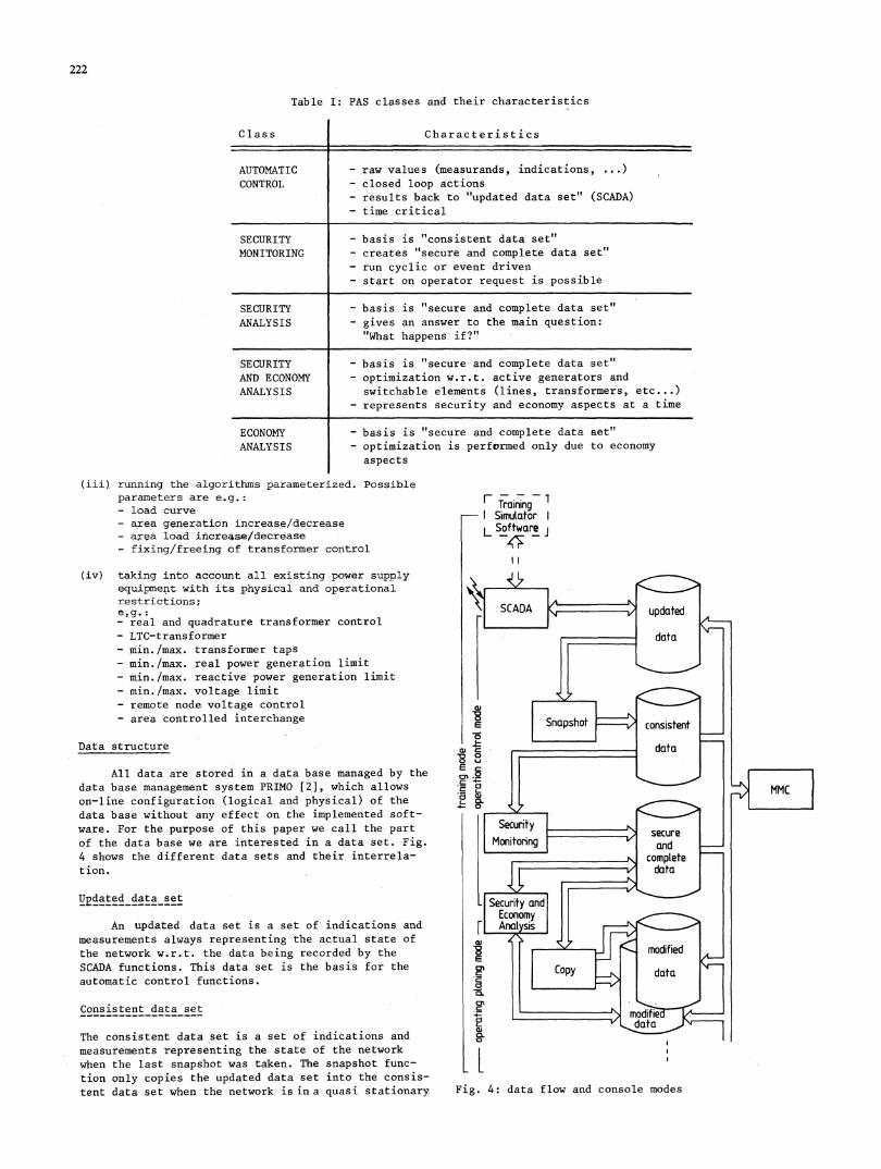
All data are stored in a data base managed by thedata base management system PRIMO [2], which allowson-line configuration (logical and physical) of thedata base without any effect on the implemented soft-ware. For the purpose of this paper we call the partof the data base we are interested in a data set. Fig.4 shows the different data sets and their interrela-tion.
Updated data set
An updated data set is a set of indications andmeasurements always representing the actual state ofthe network w.r.t. the data being recorded by theSCADA functions. This data set is the basis for theautomatic control functions.
Consistent data set
The consistent data set is a set of indications andmeasurements representing the state of the networkwhen the last snapshot was taken. The snapshot func-tion only copies the updated data set into the consis-tent data set when the network is in a quasi stationary
Training- Simulator
L Software i
I I
data flow and console modes
ECC:0,C0
CLFig. 4:
223
state. E.g. after a circuit breaker status change, thesnapshot is blocked until the system is steady and ananalogue measurement update cycle is completed. Thisdata set is the basis for security monitoring functions.When such a function is started, it requests a consis-tent data set from the snapshot function, the requestis then pending until a steady state is reached andthe copy can be made. E.g. a meaningful state estimatecan only be calculated if the analogue measurementscorrespond to the status of the circuit breakers. Theconcept of this consistent data set is applied in or-der to avoid a locking of the updated data set, whilesecurity monitoring functions are active.
The classical consistency problem, not to readand write from and to the updated data set at the sametime is solved by the data base management system viaa lock mechanism (for fairly short times).
Secure and complete data set
The secure and complete data set is a result ofthe security monitoring software. Based on the consis-tent data set
(i) topology is determined(ii) wrong measurements are marked as bad data(iii) unmeasured flows and voltages are calculated
The state estimate contained in this data set is thebasis for security and economy analysis functions.
A copy of this data set may be used for displaypurposes - so that results are available for 'an unlim-ited time- and for saving and retrieving history data.
Modified data set
The modified data sets contain (modified) copiesof the secure and complete data set. There is a modi-fied data set for each console in operation planning,mode. The network models represented by these data setsare modified via the MMC. They are used as dedicateddata sets for analysis functions.
Data sets for training simulator
When the training simulator is active, there arededicated data sets of each type for simulation pur-poses. The data structure in simulation mode is thesame'as for-the on-line system.
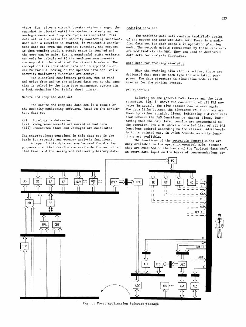
PAS functions
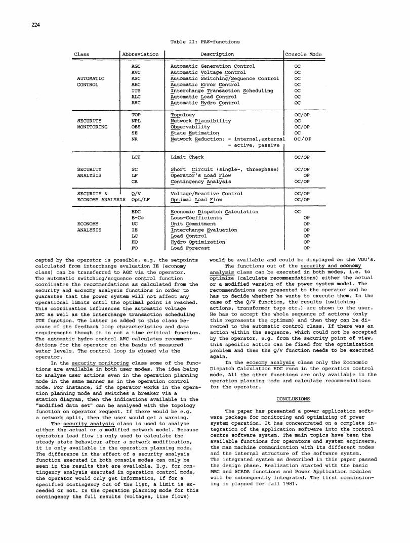
Refering to the general PAS classes and the datastructure, fig. 5 shows the connection of all PAS mo-dules in detail. The five classes can be seen again.The data links between the different PAS functions areshown by either straight lines, indicating a direct dataflow between the PAS functions or dashed lines, indi'-cating that the calculated results are recommended tothe operator. Table If shows a detailed list of all PASfunctions ordered according to the classes. Additional-ly it is pointed out, in which console mode the func-tions are' available.
The functions of the automatic control class areonly available in the operation-control mode, becausethey are executed on the basis of the "updated data set".An extra data input on the basis of recommendations ac-
Fig. 5: Power Application Software package
224
Table II: PAS-functions
Abbreviation Description Console Mode,
AGC Automatic Generation Control OCAVC Automatic Voltage Control OC
AUTOMATIC ASC Automatic Switching/Sequence Control OCCONTROL AEC Automatic Error Contro.l OC
ITS Interchange Transaction Scheduling OCALC Automatic Load Control- OCAHC Automatic Hydro Control OC
TOP Topology OC/OPSECURITY NPL NetwQrk Plausibility OCMONITORING OBS Observability OC/OP
SE State Estimation OCNR Network Reduction: - internal,external OC/OP
- active, passive
LCH Limit Check OC/OP
SECURITY SC Short Circuit (single-, threephase) OC/OPANALYSIS LF Operator's Load Flow OP
CA Contingency Analysis OC/OP
SECURITY & Q/V Voltage/Reactive Control OC/OPECONOMY ANALYSIS Opt/LF Optimal Load Flow OC/OP
__ __ _ __ _ I__
ECONOMYANALYSIS
EDCB-CoU.CIELCHOFO
Economic Dispatch CalculationLoss-CoefficientsUnit CommitmentInterchange EvaluationLoad ControlHydro OptimizationLoad Forecast
OC
OPOPOPOPOPOP
cepted by the operator is possible, e.g. the setpointscalculated from interchange evaluation IE (economyclass) can be transferred to AGC via the operator.The automatic switching/sequence control functioncoordinates the recommendations as calculated from thesecurity and economy analysis functions in order toguarantee that the power system will not affect any
operational limits until the optimal point is reached.This coordination influences the automatic voltageAVC as well as the intercha,nge transaction schedulingITS function. The latter is added to this class be-cause of its feedback loop characteristics and datarequirements though it is not a time critical function.The automatic hydro control AHC calculates recommen-
dations for the:operator on the basis of measured
water levels. The control loop is closed via theoperator.
In the security monitoring class some of the func-tions are available in both user modes. The idea beingto analyse user actions even in the operation planningmode in the same manner as in the operation controlmode. For instance, if the operator works in the opera-
tion planning mode and switches a breaker via a
station diagram,, then the indications available.in the"modified data set" can be analysed with the topologyfunction on operator request. If there would be e.g.
a network split, then the user would get a warning.The security analysis class is used to analyse
either the actual or a modified network model. Becauseoperators load flow is only used to calculate thesteady state behaviour after a network modification,it is only available in the operation planning mode.The difference in the effect of a security analysisfunction executed in both console modes can only beseen in the results that are-available. E.g. for con-
tingency analysis executed in operation control mode,the operator would only get information, if for a
specified contingency out of the list, a limit is ex-
ceeded or not. In the operation pl4nning mode for thiscontingency the full results (voltages, line flows)
would be available and could be displayed on the VDU's.
The functions out of the security and economyanalysis class can be executed in both modes, i.e. to
optimize (calculate recommendations) either the actualor a,modified version of the power system-model. The
recommendations are presented to the operator-and hehas to decide whether he wants to execute them. In the
case of the Q/V function, the'results (switchingactions, transformer taps etc.) are shown to the user.
He has to accept the whole sequence of actions (onlythis represents the optimum) and then they can be di-rected to the automatic control class. If there was anaction within the sequence, which could not be acceptedby the operator, e.g. from the security point of view,this specific action can be fixed for the optimizationproblem and then the Q/V function needs to be executedagain.
In the economy analysis class only the EconomicDispatch Calculation EDC runs in the operation contro.lmode. All the other functions are only available in theoperation planning mode and calculate recommendationsfor the operator.
CONCLUSIONS
The paper has presented a power application soft-ware package for monitoring and optimizing of power-
system operation. It has concentrated on a complete in-tegration of the application software into the controlcentre software system.-The main topics have been theavailable functions for operators and system engineers,the man machine communication with its different modesand the internal structure of the software system.The integrated system as described in this paper passedthe design phase. Realization started with the basicMMC and SCADA functions and Power Application moduleswill be subsequently integrated. The first commission-ing is planned for fall 1981.
Class

225
REFERENCES
1 G. Schaffer, K. Ebert, A. Ess, 0. Bissat, A. J.Germond, "Training Simulator for Power SystemOperations", Submitted to PICA conference 1981,Philadelphia, PA.
2 K. Fruhauf, H. Koller and J. Muheim, "PRIMO - aMultiprogramming Real-Time Database System forEnergy Distribution Applications", Proceedings ofthe 6th PSCC, Darmstadt, 1978, Vol. 1, pp 371-376.