Embed Size (px)
Citation preview
8/6/2019 AN203 Compass Heading Using Magnetometers
http://slidepdf.com/reader/full/an203-compass-heading-using-magnetometers 1/2
COMPASS HEADING USING MAGNETOMETERS AN-203
HoneywellÕs line of magnetoresistive permalloy sensorsare sensitive to magnetic fields less than 100 µgausswithin a ±2 gauss range. This sensitivity can becompared to the earthÕs magnetic field which is roughly
0.6 gauss (48 A/m) and results in a measurementresolution of 1 part in 6,000. This applications note willdiscuss basic principles of compass headings andprovide a method for compassing using the HoneywellSmart Digital Magnetometer.
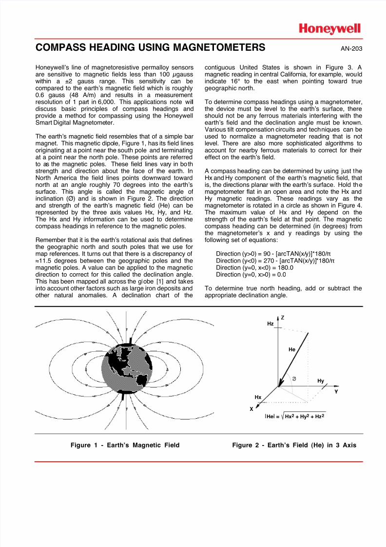
The earthÕs magnetic field resembles that of a simple barmagnet. This magnetic dipole, Figure 1, has its field linesoriginating at a point near the south pole and terminatingat a point near the north pole. These points are referredto as the magnetic poles. These field lines vary in bothstrength and direction about the face of the earth. InNorth America the field lines points downward towardnorth at an angle roughly 70 degrees into the earthÕs
surface. This angle is called the magnetic angle ofinclination (¯) and is shown in Figure 2. The directionand strength of the earthÕs magnetic field (He) can berepresented by the three axis values Hx, Hy, and Hz.The Hx and Hy information can be used to determinecompass headings in reference to the magnetic poles.
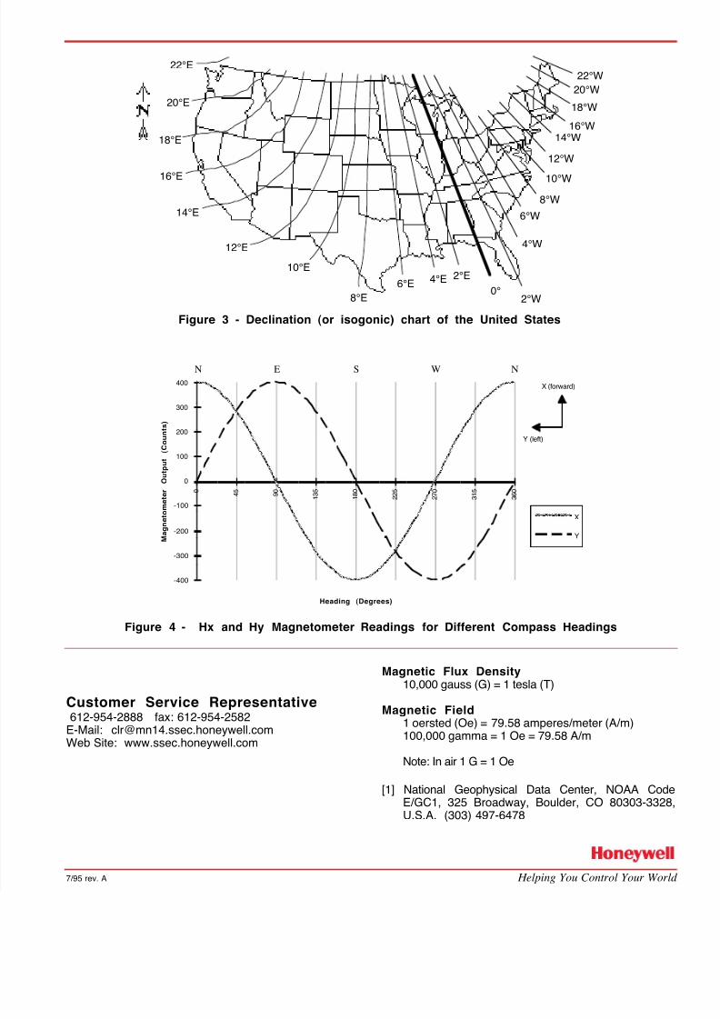
Remember that it is the earthÕs rotational axis that definesthe geographic north and south poles that we use formap references. It turns out that there is a discrepancy ofÅ11.5 degrees between the geographic poles and themagnetic poles. A value can be applied to the magneticdirection to correct for this called the declination angle.This has been mapped all across the globe [1] and takes
into account other factors such as large iron deposits andother natural anomalies. A declination chart of the
contiguous United States is shown in Figure 3. Amagnetic reading in central California, for example, wouldindicate 16¡ to the east when pointing toward truegeographic north.
To determine compass headings using a magnetometerthe device must be level to the earthÕs surface, thereshould not be any ferrous materials interfering with theearthÕs field and the declination angle must be knownVarious tilt compensation circuits and techniques can beused to normalize a magnetometer reading that is nolevel. There are also more sophisticated algorithms toaccount for nearby ferrous materials to correct for theieffect on the earthÕs field.
A compass heading can be determined by using just theHx and Hy component of the earthÕs magnetic field, thatis, the directions planar with the earthÕs surface. Hold the
magnetometer flat in an open area and note the Hx andHy magnetic readings. These readings vary as themagnetometer is rotated in a circle as shown in Figure 4The maximum value of Hx and Hy depend on thestrength of the earthÕs field at that point. The magneticcompass heading can be determined (in degrees) fromthe magnetometerÕs x and y readings by using thefollowing set of equations:
Direction (y>0) = 90 - [arcTAN(x/y)]*180/¹Direction (y<0) = 270 - [arcTAN(x/y)]*180/¹Direction (y=0, x<0) = 180.0Direction (y=0, x>0) = 0.0
To determine true north heading, add or subtract theappropriate declination angle.
X
Hx
Hz
Hy
He
|He| = Hx2 + Hy2 + Hz2
Figure 1 - EarthÕs Magnetic Field Figure 2 - EarthÕs Field (He) in 3 Axis
8/6/2019 AN203 Compass Heading Using Magnetometers
http://slidepdf.com/reader/full/an203-compass-heading-using-magnetometers 2/2
7/95 rev. A Helping You Control Your World
22¡E
20¡E
18¡E
16¡E
14¡E
12¡E
10¡E
8¡E
6¡E2¡E
0¡4¡E
2¡W
4¡W
18¡W
16¡W14¡W
12¡W
10¡W
8¡W
6¡W
20¡W
22¡W
Figure 3 - Declination (or isogonic) chart of the United States
Heading (Degrees)
M a g n e t o m e t e r
O u t p u t
( C o u n t s )
-400
-300
-200
-100
0
100
200
300
400
0 4 5
9 0
1 3 5
1 8 0
2 2 5
2 7 0
3 1 5
3 6 0
X
Y
N E S W N
X (forward)
Y (left)
Figure 4 - Hx and Hy Magnetometer Readings for Different Compass Headings
Customer Service Representative612-954-2888 fax: 612-954-2582
E-Mail: [email protected] Site: www.ssec.honeywell.com
Magnetic Flux Density10,000 gauss (G) = 1 tesla (T)
Magnetic Field1 oersted (Oe) = 79.58 amperes/meter (A/m)100,000 gamma = 1 Oe = 79.58 A/m
Note: In air 1 G = 1 Oe
[1] National Geophysical Data Center, NOAA CodeE/GC1, 325 Broadway, Boulder, CO 80303-3328U.S.A. (303) 497-6478