Embed Size (px)
Citation preview

ANALOG ELECTRONICS LABORATORY
AEL1037-ADV ADVANCED POWER ELECTRONICS TRAINER
MP-SCIENTIFIC
EXPERIMENTS LIST
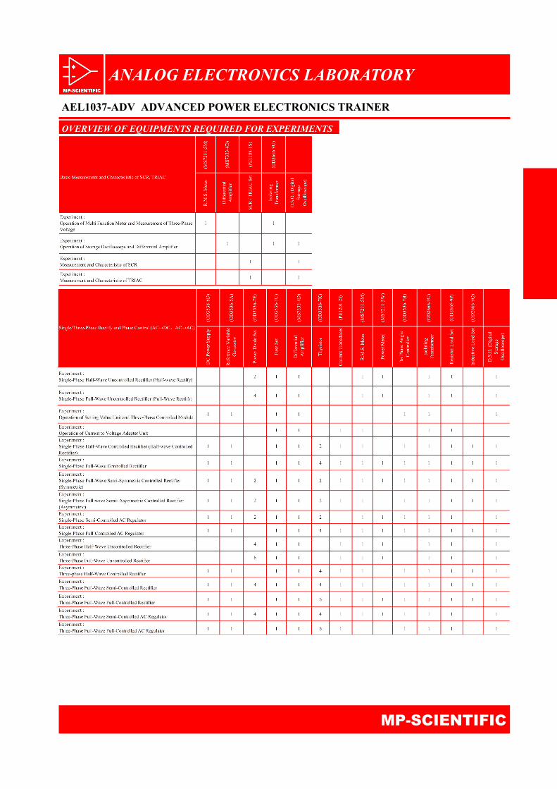
Basic Measurement and Characteristic of SCR, TRIAC Operation of R.M.S. meter and measurement of three-phase voltage
Operation of storage oscilloscope and differential
amplifier
Measurement and characteristic of SCR
Measurement and characteristic of TRIAC Single/Three-Phase Rectify and Phase Control
(AC→DC,AC→AC)
Single-phase half-wave uncontrolled rectifier (Half‑wave rec-tify)
Single-phase full-wave uncontrolled rectifier (Full‑wave rec-tify)
Operation of reference variable generator and three phase angle controller
Operation of voltage/current to measuring transducer
Single-phase half-wave controlled rectifier (Half‑wave con-trolled rectifier)
Single-phase full-wave controlled rectifier
Single-phase full-wave semi- symmetric - controlled rectifier (Symmetric)
Single-phase full-wave semi- asymmetric - controlled rectifier (Asymmetric)
Single-phase semi-controlled AC regulator
Single-phase full-controlled AC regulator
Three-phase half-wave uncontrolled rectifier
Three-phase full-wave uncontrolled rectifier
Three-phase half-wave controlled rectifier
Three-phase full-wave semi-controlled rectifier
Three-phase full-wave full-controlled rectifier
Three-phase full-wave semi-controlled AC regulator
Three-phase full-wave full-controlled AC regulator
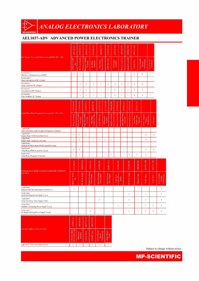
DC Chopper Circuit and Characteristic of IGBT
(DC→DC)
Measurement and characteristic of IGBT
Basic description of DC chopper
Single quadrant DC chopper
Two quadrant DC chopper
Four quadrant DC chopper Single/Three-Phase Frequency Converter
(AC→DC→AC)
Basic description and principle of frequency converter
Single-phase PWM controller circuit
Single-phase frequency converter
Analysis of Three-phase PWM controller circuit
Three-phase PWM controller circuit
Three-phase frequency converter Switching Power Supply Circuit and Characteristic of MOSFET (DC→DC)
Measurement and characteristic of MOSFET
Buck switching power supply
Boost switching power supply
Buck-boost switching power supply
Fly-back switching power supply Electronic Ballast Circuit (AC→AC)
ANALOG ELECTRONICS LABORATORY
MP-SCIENTIFIC
AEL1037-ADV ADVANCED POWER ELECTRONICS TRAINER
MODULES LIST
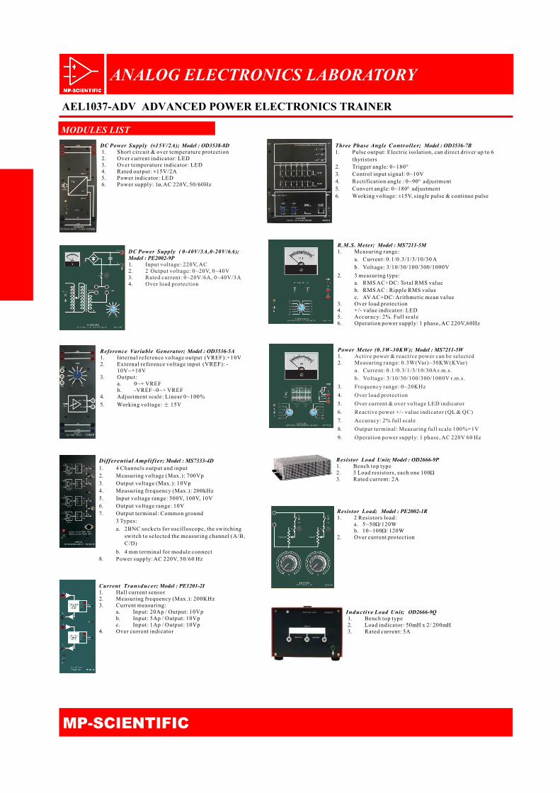
Resistor Load Unit; Model : OD2666-9P 1. Bench top type 2. 3 Load resistors, each one 100Ω 3. Rated current: 2A
DC Power Supply (±15V/2A); Model : OD3538-8D 1. Short circuit & over temperature protection 2. Over current indicator: LED 3. Over temperature indicator: LED 4. Rated output: ±15V/2A 5. Power indicator: LED 6. Power supply: 1ø, AC 220V, 50/60Hz
DC Power Supply ( 0-40V/3A,0-20V/6A); Model : PE2002-9P 1. Input voltage: 220V, AC 2. 2 Output voltage: 0~20V, 0~40V 3. Rated current: 0~20V/6A, 0~40V/3A 4. Over load protection
Reference Variable Generator; Model : OD3536-5A 1. Internal reference voltage output (VREF):+10V 2. External reference voltage input (VREF): -
10V~+10V 3. Output:
a. 0~+ VREF b. -VREF~0~+ VREF
4. Adjustment scale: Linear 0~100%
5. Working voltage: ± 15V
Differential Amplifier; Model : MS7333-4D 1. 4 Channels output and input 2. Measuring voltage (Max.): 700Vp 3. Output voltage (Max.): 10Vp 4. Measuring frequency (Max.): 200kHz 5. Input voltage range: 500V, 100V, 10V 6. Output voltage range: 10V 7. Output terminal: Common ground
3 Types:
a. 2BNC sockets for oscilloscope, the switching switch to selected the measuring channel (A/B, C/D)
b. 4 mm terminal for module connect 8. Power supply: AC 220V, 50/60 Hz
Current Transducer; Model : PE1201-2I 1. Hall current sensor 2. Measuring frequency (Max.): 200KHz 3. Current measuring:
a. Input: 20Ap / Output: 10Vp b. Input: 5Ap / Output: 10Vp c. Input: 1Ap / Output: 10Vp
4. Over current indicator
Three Phase Angle Controller; Model : OD3536-7B 1. Pulse output: Electric isolation, can direct driver up to 6
thyristors 2. Trigger angle: 0~180° 3. Control input signal: 0~10V 4. Rectification angle : 0~90° adjustment 5. Convert angle: 0~180° adjustment 6. Working voltage: ±15V, single pulse & continue pulse
R.M.S. Meter; Model : MS7211-5M 1. Measuring range:
a. Current: 0.1/0.3/1/3/10/30 A
b. Voltage: 3/10/30/100/300/1000V
2. 3 measuring type: a. RMS AC+DC: Total RMS value b. RMS AC : Ripple RMS value c. AV AC+DC: Arithmetic mean value
3. Over load protection 4. +/- value indicator: LED 5. Accuracy: 2%. Full scale 6. Operation power supply: 1 phase, AC 220V,60Hz
Power Meter (0.3W-30KW); Model : MS7211-5W 1. Active power & reactive power can be selected 2. Measuring range: 0.3W(Var)~30KW(KVar)
a. Current: 0.1/0.3/1/3/10/30A r.m.s.
b. Voltage: 3/10/30/100/300/1000V r.m.s.
3. Frequency range: 0~20KHz
4. Over load protection
5. Over current & over voltage LED indicator
6. Reactive power +/- value indicator (QL & QC)
7. Accuracy: 2% full scale
8. Output terminal: Measuring full scale 100%=1V
9. Operation power supply: 1 phase, AC 220V 60 Hz
Resistor Load; Model : PE2002-1R 1. 2 Resistors load:
a. 5~50Ω/120W b. 10~100Ω/ 120W
2. Over current protection
Inductive Load Unit; OD2666-9Q 1. Bench top type 2. Load indicator: 50mH x 2/ 200mH 3. Rated current: 5A
ANALOG ELECTRONICS LABORATORY
AEL1037-ADV ADVANCED POWER ELECTRONICS TRAINER
MP-SCIENTIFIC
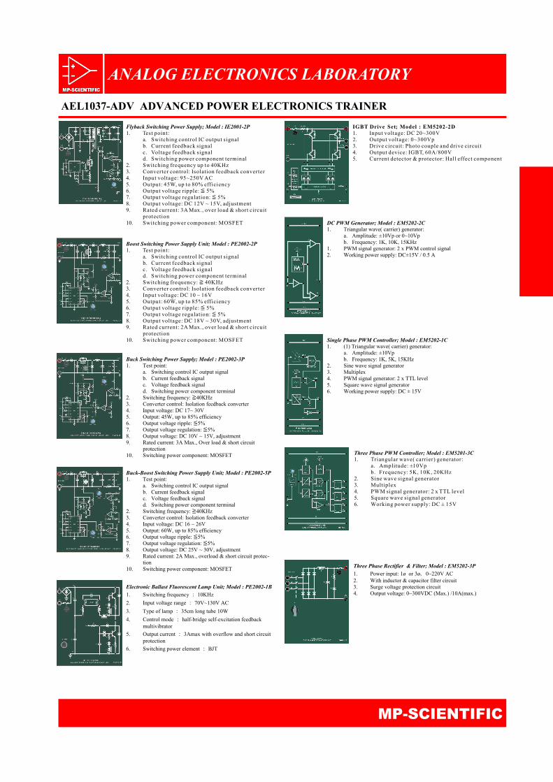
Flyback Switching Power Supply; Model : IE2001-2P 1. Test point:
a. Switching control IC output signal b. Current feedback signal c. Voltage feedback signal d. Switching power component terminal
2. Switching frequency up to 40KHz 3. Converter control: Isolation feedback converter 4. Input voltage: 95~250V AC 5. Output: 45W, up to 80% efficiency 6. Output voltage ripple: ≦ 5% 7. Output voltage regulation: ≦ 5% 8. Output voltage: DC 12V ~ 15V, adjustment 9. Rated current: 3A Max., over load & short circuit
protection 10. Switching power component: MOSFET
Boost Switching Power Supply Unit; Model : PE2002-2P 1. Test point:
a. Switching control IC output signal b. Current feedback signal c. Voltage feedback signal d. Switching power component terminal
2. Switching frequency: ≧ 40KHz 3. Converter control: Isolation feedback converter 4. Input voltage: DC 10 ~ 16V 5. Output: 60W, up to 85% efficiency 6. Output voltage ripple: ≦ 5% 7. Output voltage regulation: ≦ 5% 8. Output voltage: DC 18V ~ 30V, adjustment 9. Rated current: 2A Max., over load & short circuit
protection 10. Switching power component: MOSFET
Buck Switching Power Supply; Model : PE2002-3P 1. Test point:
a. Switching control IC output signal b. Current feedback signal c. Voltage feedback signal d. Switching power component terminal
2. Switching frequency: ≧40KHz 3. Converter control: Isolation feedback converter 4. Input voltage: DC 17~ 30V 5. Output: 45W, up to 85% efficiency 6. Output voltage ripple: ≦5% 7. Output voltage regulation: ≦5% 8. Output voltage: DC 10V ~ 15V, adjustment 9. Rated current: 3A Max., Over load & short circuit
protection 10. Switching power component: MOSFET
Buck-Boost Switching Power Supply Unit; Model : PE2002-5P 1. Test point:
a. Switching control IC output signal b. Current feedback signal c. Voltage feedback signal d. Switching power component terminal
2. Switching frequency: ≧40KHz 3. Converter control: Isolation feedback converter 4. Input voltage: DC 16 ~ 26V 5. Output: 60W, up to 85% efficiency 6. Output voltage ripple: ≦5% 7. Output voltage regulation: ≦5% 8. Output voltage: DC 25V ~ 30V, adjustment 9. Rated current: 2A Max., overload & short circuit protec-
tion 10. Switching power component: MOSFET
Electronic Ballast Fluorescent Lamp Unit; Model : PE2002-1B
1. Switching frequency : 10KHz
2. Input voltage range : 70V~130V AC
3. Type of lamp : 35cm long tube 10W
4. Control mode : half-bridge self-excitation feedback multivibrator
5. Output current : 3Amax with overflow and short circuit protection
6. Switching power element : BJT
IGBT Drive Set; Model : EM5202-2D 1. Input voltage: DC 20~300V 2. Output voltage: 0~300Vp 3. Drive circuit: Photo couple and drive circuit 4. Output device: IGBT, 60A/800V 5. Current detector & protector: Hall effect component
DC PWM Generator; Model : EM5202-2C 1. Triangular wave( carrier) generator:
a. Amplitude: ±10Vp or 0~10Vp b. Frequency: 1K, 10K, 15KHz
1. PWM signal generator: 2 x PWM control signal 2. Working power supply: DC±15V / 0.5 A
Single Phase PWM Controller; Model : EM5202-1C 1. (1) Triangular wave( carrier) generator:
a. Amplitude: ±10Vp b. Frequency: 1K, 5K, 15KHz
2. Sine wave signal generator 3. Multiplex 4. PWM signal generator: 2 x TTL level 5. Square wave signal generator 6. Working power supply: DC ± 15V
Three Phase PWM Controller; Model : EM5201-3C 1. Triangular wave( carrier) generator:
a. Amplitude: ±10Vp b. Frequency: 5K, 10K, 20KHz
2. Sine wave signal generator 3. Multiplex 4. PWM signal generator: 2 x TTL level 5. Square wave signal generator 6. Working power supply: DC ± 15V
Three Phase Rectifier & Filter; Model : EM5202-3P
1. Power input: 1ø or 3ø, 0~220V AC 2. With inductor & capacitor filter circuit 3. Surge voltage protection circuit 4. Output voltage: 0~300VDC (Max.) /10A(max.)
ANALOG ELECTRONICS LABORATORY
MP-SCIENTIFIC
AEL1037-ADV ADVANCED POWER ELECTRONICS TRAINER
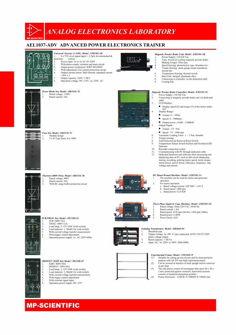
Magnetic Powder Brake Unit; Model : EM5101-3B 1. Power Supply: 110/220 Vac 2. Type: forced air-cooling magnetic powder brake 3. Braking Torque: 5Nm max. 4. Speed Sensing: photoelectric type, 60 pulses/rev. 5. Torque Sensing: strain-gauge torque transducer,
torsion bar 6. Temperature Sensing: thermal switch 7. Base Unit: integral, aluminum alloy 8. Connecting to controller via the dedicated cable 9. Cooling Fan
Magnetic Powder Brake Controller; Model : EM5101-3C 1. Power Supply: 110/240 Vac 2. Connecting to magnetic powder brake unit via dedicated
cable 3. LCD Display:
Display speed (S) and torque (T) of the motor under test
4. Display Range:
Torque: 0 ~ 10Nm
Speed: 0 ~ 5000rpm
Output power ; 0.000 ~ 2.000kW 5. Output Signal :
Torque : 1V / Nm
Speed : 1V / 1000 rpm 6. Automatic Loading Limit : 1 ~ 5 Nm; Settable 7. Torque zeroing 8. Fault Detection & Removal Reset Switch 9. Temperature Sensor Switch Sockets and Overheat LED
Indicator 10. Recorder connection socket 11. Communicating with PC through dedicated cable 12. Dedicated hardware and software allow processing and
displaying data on PC, such as full screen displaying, tracing, recording, printing motor speed, motor torque, motor power, power factor, efficiency, frequency, slip, voltage and current.
Universal Inverter 3×230V; Model : EM5201-3D 1. 6 x TTL level signal input: > 2.5μS, for interlocked & dead time control 2. Power input: 1ø or 3ø AC 20~220V 3. With photo-couple, isolation and main circuit 4. Output power component: IGBT 60A/800V 5. With adjustment over current protection circuit. 6. Output current sensor: Hall element, saturated current
>50A x 2 7. Output capacity: 220V/ 1.5KV 8. Operation voltage: DC ±15V, 1ø, 220V, AC
Power Diode Set; Model : OD3536-7E 1. Rated voltage: 1100V 2. Rated current: 10A
Fuse Set; Model : OD3536-7U 1. Module design 2. 3 x D-Type fuses, 6A/ 500V
Thyristor (800V/10A); Model : OD3536-7K 1. Rated voltage: 800V 2. Rated current: 10A 3. With RC surge buffer protection circuit
SCR/TRIAC Set; Model : PE1188-1S 1. SCR: 600V/16A 2. TRIAC: 600V/12A 3. Load lamp: 2, 12V/10W (with switch) 4. Load inductor: 1, 50mH/1A( with switch) 5. With current/voltage transfer measurement 6. With trigger control adjustment 7. Operation power supply: 1ø AC 220V/60Hz
MOSFET / IGBT Set; Model : PE1188-1F 1. IGBT: 800V/50A 2. MOSFET: 100V/48A 3. Load lamp: 2, 12V/10W (with switch) 4. Load inductor: 1, 50mH/1A( with switch) 5. With current/voltage transfer measurement 6. With trigger control adjustment 7. With external signal input 8. Operation power supply: DC+15V
DC Shunt Wound Machine; Model : EM5101-3A 1. The machine can be used for motor and generator
operation 2. For motor operation:
a. Rated voltage/current: 220 VDC / 1.65 A b. Rated speed: 1800 rpm c. Rated power: 0.25 KW
Three-Phase Squirrel Cage Machine; Model : EM5101-3G 1. Rated voltage: Delta 220 VAC, 50/60 Hz 2. Rated current: 1.4A 3. Rated speed: 1670 rpm (60 Hz), 1420 rpm (50Hz) 4. Rated power: 0.3KW 5. Power factor: 0.82
Isolating Transformer; Model : OD2666-9U 1. Benchtop type 2. Output voltage: 3ø, 4W, Y type connected, 64/95/110/127/220V
phase voltage output 3. Rated capacity: 1.5KVA 4. Input: AC, 3ø, 220V or 380V, 50Hz/60Hz
Experimental Frame; Model : FM1260-3T (1) Suitable for setting up test circuits and for demonstration
purpose with A4 297 mm high experiment panels (2) Can be secured to benches or back upright and be removed
at any time (3) The side pieces consist of rectangular tube steel. 60 x 30 x
2 mm, protected against corrosion, horizontal sections consists of anodized aluminium profiles
(4) Frame dimension : 1250(W) X 1000(H) X 250(D) mm
ANALOG ELECTRONICS LABORATORY
AEL1037-ADV ADVANCED POWER ELECTRONICS TRAINER
MP-SCIENTIFIC
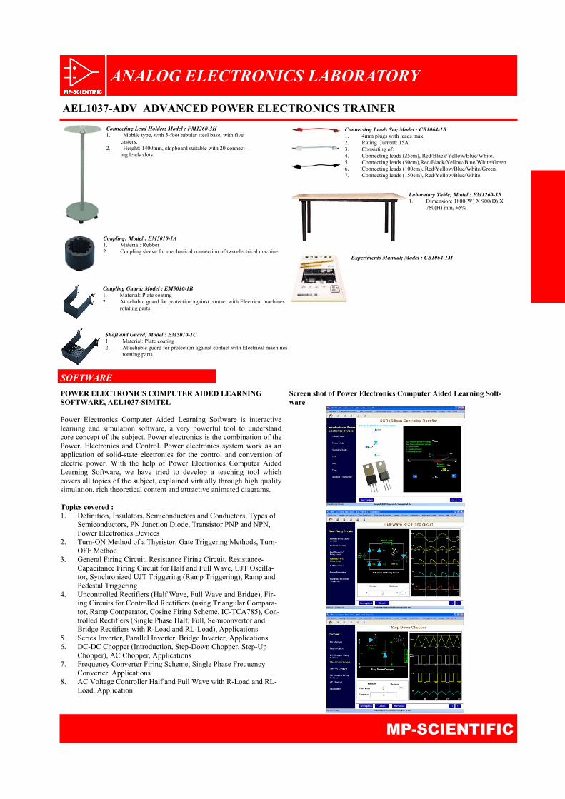
Laboratory Table; Model : FM1260-3B 1. Dimension: 1800(W) X 900(D) X
780(H) mm, ±5%
Connecting Lead Holder; Model : FM1260-3H 1. Mobile type, with 5-foot tubular steel base, with five
casters. 2. Height: 1400mm, chipboard suitable with 20 connect-
ing leads slots.
Coupling; Model : EM5010-1A 1. Material: Rubber 2. Coupling sleeve for mechanical connection of two electrical machine
Coupling Guard; Model : EM5010-1B 1. Material: Plate coating 2. Attachable guard for protection against contact with Electrical machines
rotating parts
Shaft and Guard; Model : EM5010-1C 1. Material: Plate coating 2. Attachable guard for protection against contact with Electrical machines
rotating parts
Connecting Leads Set; Model : CB1064-1B 1. 4mm plugs with leads max. 2. Rating Current: 15A 3. Consisting of: 4. Connecting leads (25cm), Red/Black/Yellow/Blue/White. 5. Connecting leads (50cm),Red/Black/Yellow/Blue/White/Green. 6. Connecting leads (100cm), Red/Yellow/Blue/White/Green. 7. Connecting leads (150cm), Red/Yellow/Blue/White.
Experiments Manual; Model : CB1064-1M
SOFTWARE
POWER ELECTRONICS COMPUTER AIDED LEARNING SOFTWARE, AEL1037-SIMTEL Power Electronics Computer Aided Learning Software is interactive learning and simulation software, a very powerful tool to understand core concept of the subject. Power electronics is the combination of the Power, Electronics and Control. Power electronics system work as an application of solid-state electronics for the control and conversion of electric power. With the help of Power Electronics Computer Aided Learning Software, we have tried to develop a teaching tool which covers all topics of the subject, explained virtually through high quality simulation, rich theoretical content and attractive animated diagrams. Topics covered : 1. Definition, Insulators, Semiconductors and Conductors, Types of
Semiconductors, PN Junction Diode, Transistor PNP and NPN, Power Electronics Devices
2. Turn-ON Method of a Thyristor, Gate Triggering Methods, Turn-OFF Method
3. General Firing Circuit, Resistance Firing Circuit, Resistance-Capacitance Firing Circuit for Half and Full Wave, UJT Oscilla-tor, Synchronized UJT Triggering (Ramp Triggering), Ramp and Pedestal Triggering
4. Uncontrolled Rectifiers (Half Wave, Full Wave and Bridge), Fir-ing Circuits for Controlled Rectifiers (using Triangular Compara-tor, Ramp Comparator, Cosine Firing Scheme, IC-TCA785), Con-trolled Rectifiers (Single Phase Half, Full, Semiconvertor and Bridge Rectifiers with R-Load and RL-Load), Applications
5. Series Inverter, Parallel Inverter, Bridge Inverter, Applications 6. DC-DC Chopper (Introduction, Step-Down Chopper, Step-Up
Chopper), AC Chopper, Applications 7. Frequency Converter Firing Scheme, Single Phase Frequency
Converter, Applications 8. AC Voltage Controller Half and Full Wave with R-Load and RL- Load, Application
Screen shot of Power Electronics Computer Aided Learning Soft-ware
ANALOG ELECTRONICS LABORATORY
AEL1037-ADV ADVANCED POWER ELECTRONICS TRAINER
MP-SCIENTIFIC
OVERVIEW OF EQUIPMENTS REQUIRED FOR EXPERIMENTS
ANALOG ELECTRONICS LABORATORY
AEL1037-ADV ADVANCED POWER ELECTRONICS TRAINER
MP-SCIENTIFIC Subject to change without notice