Embed Size (px)
Citation preview
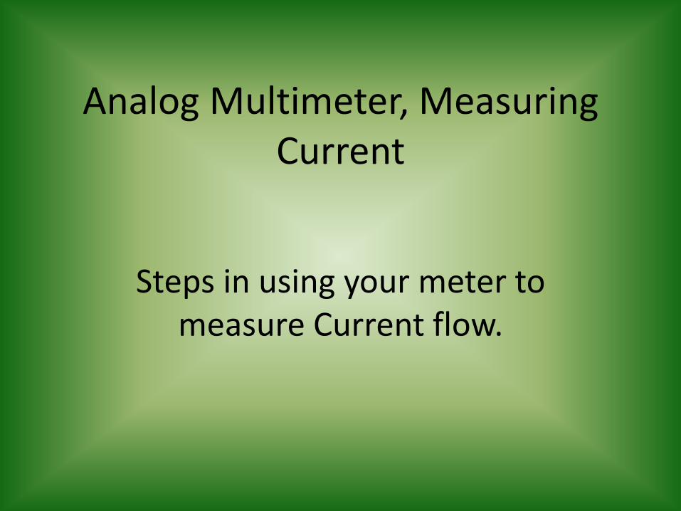
Analog Multimeter, Measuring Current
Steps in using your meter to measure Current flow.
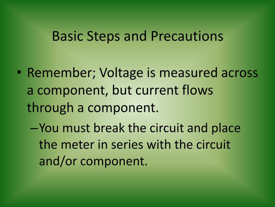
Basic Steps and Precautions
• Remember; Voltage is measured across a component, but current flows through a component.
–You must break the circuit and place the meter in series with the circuit and/or component.

• This is not a “Auto-ranging Digital Multimeter! Pay attention to the polarity of the circuit components and the lead placement.
–The Black Lead is the Negative Lead.
–The Red Lead is the Positive Lead.

• It does not hurt to start with the Function switch at a high level and decrease to a lower level.
• It is still a good idea to try to read the value about mid scale or mid range on the meter.
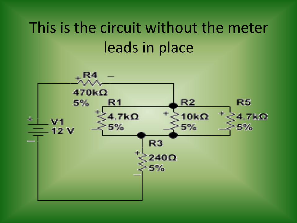
This is the circuit without the meter leads in place
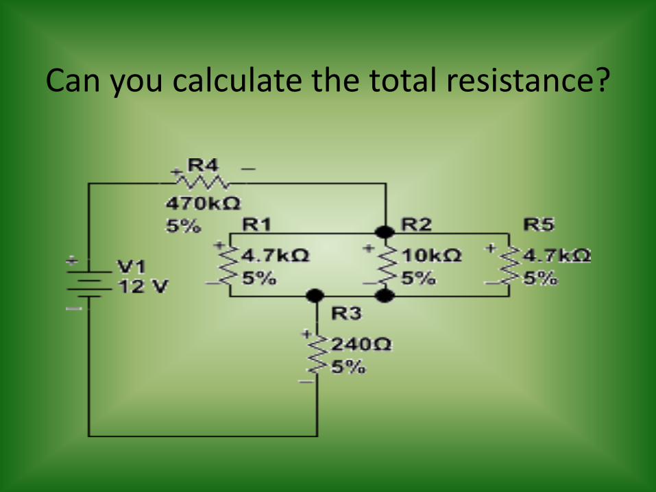
Can you calculate the total resistance?

We are going to calculate IT
• We do this to practice using the Ohms Law formulas you learned previously, to verify Kirchhoff’s Laws do work and to know what current to expect.
• We will first calculate RT
• We will next use the VT which is a given to calculate IT
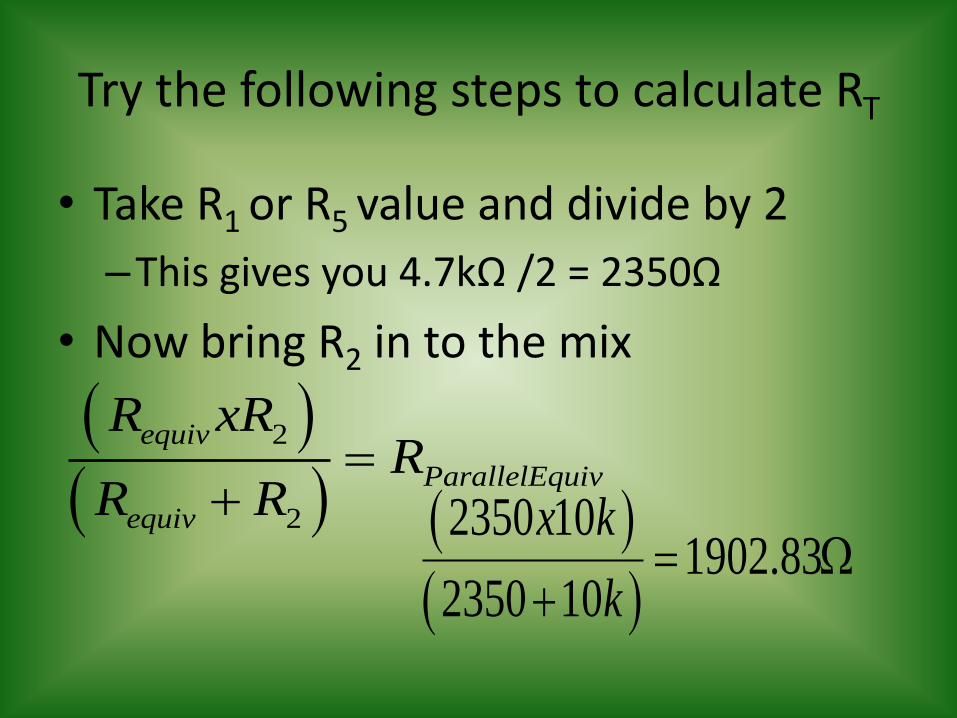
Try the following steps to calculate RT
• Take R1 or R5 value and divide by 2
–This gives you 4.7kΩ /2 = 2350Ω
• Now bring R2 in to the mix
2
2
equiv
ParallelEquiv
equiv
R xRR
R R
2350 101902.83
2350 10
x k
k
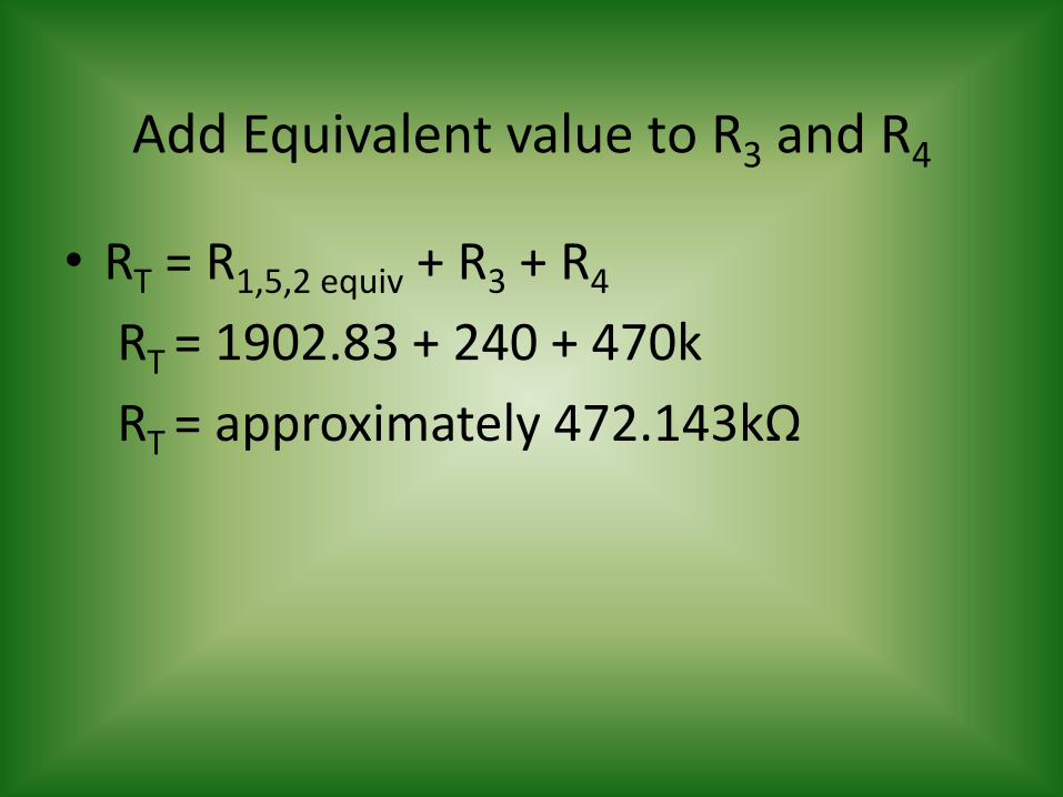
Add Equivalent value to R3 and R4
• RT = R1,5,2 equiv + R3 + R4
RT = 1902.83 + 240 + 470k
RT = approximately 472.143kΩ
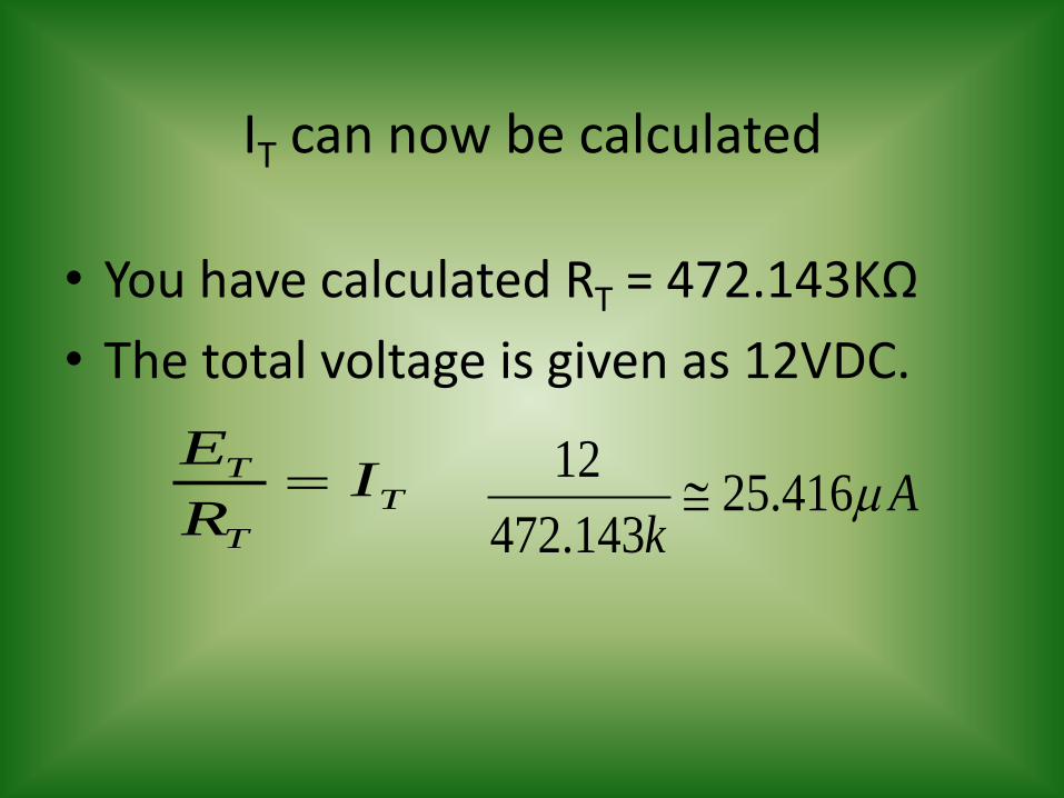
IT can now be calculated
• You have calculated RT = 472.143KΩ
• The total voltage is given as 12VDC.
TT
T
EI
R 12
25.416472.143
Ak
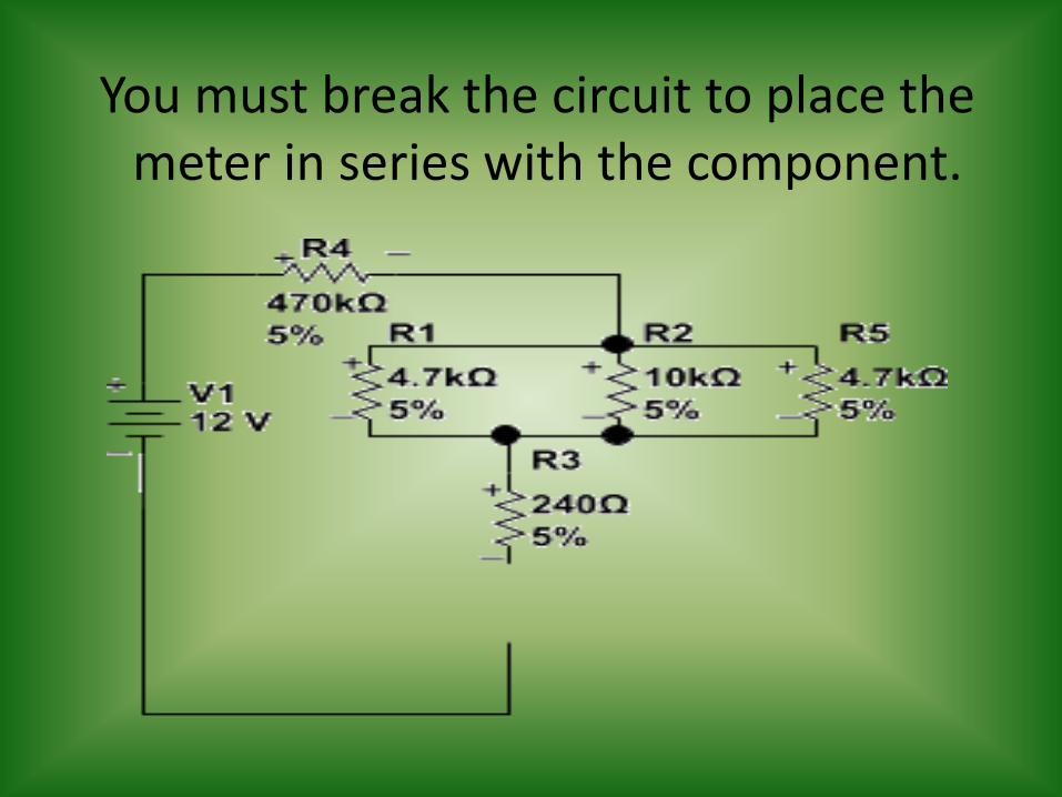
You must break the circuit to place the meter in series with the component.

Remember to start at a higher level

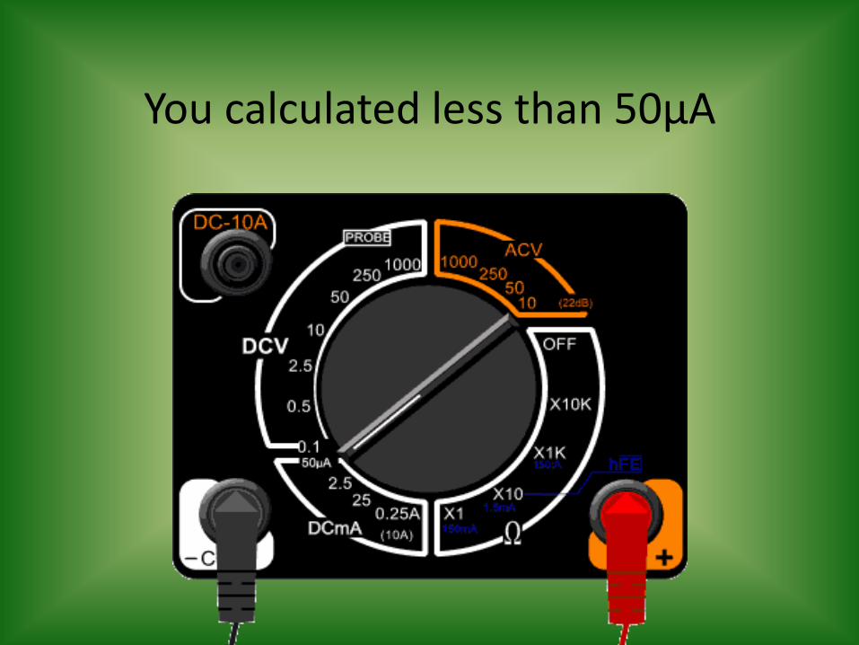
You calculated less than 50µA
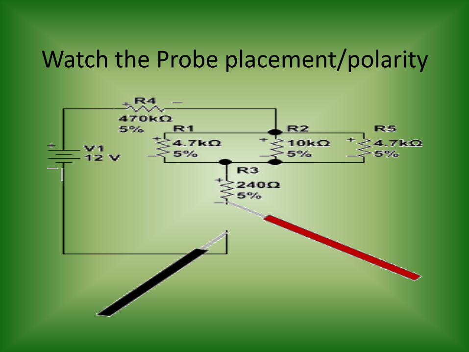
Watch the Probe placement/polarity
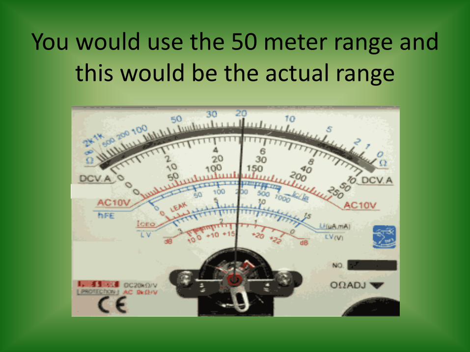
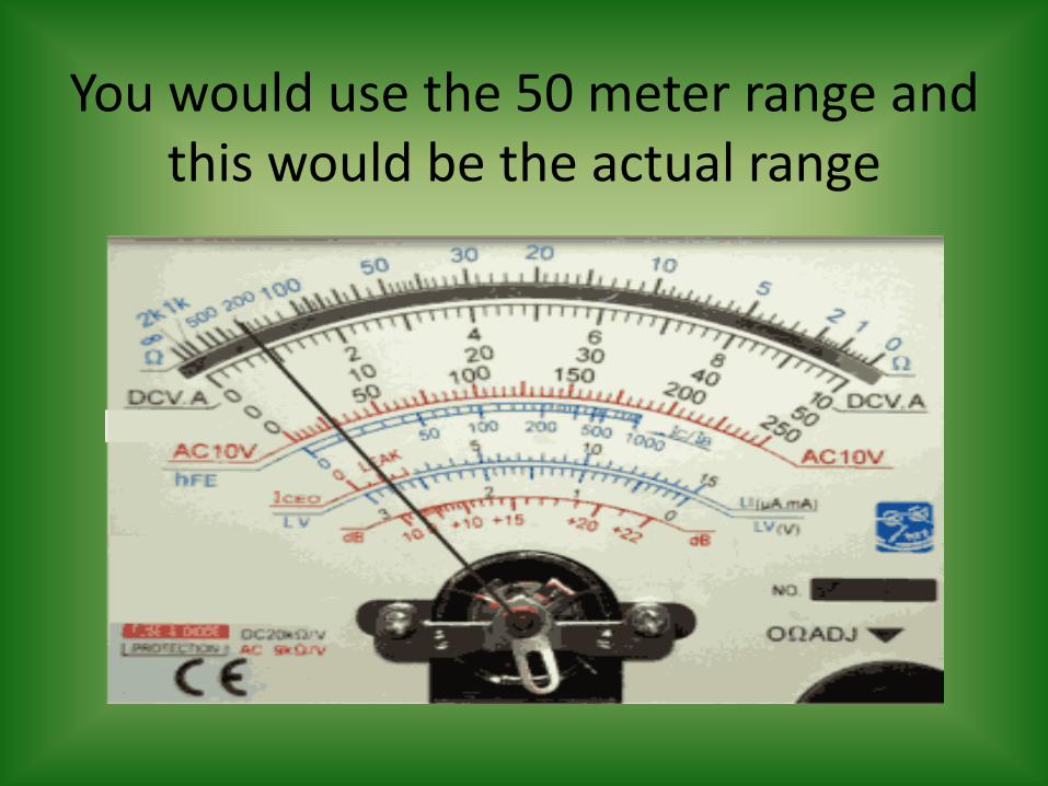
You would use the 50 meter range and this would be the actual range
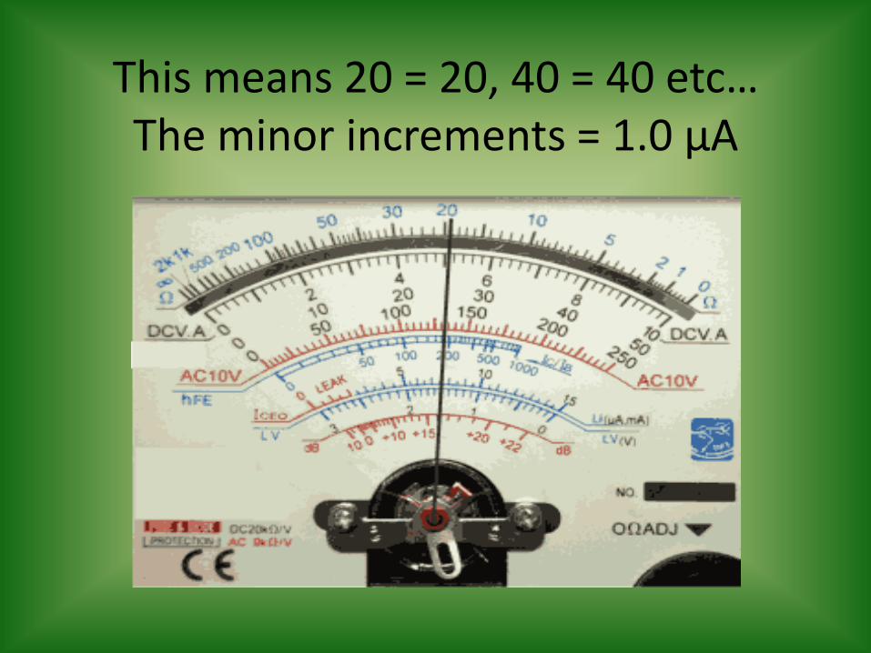
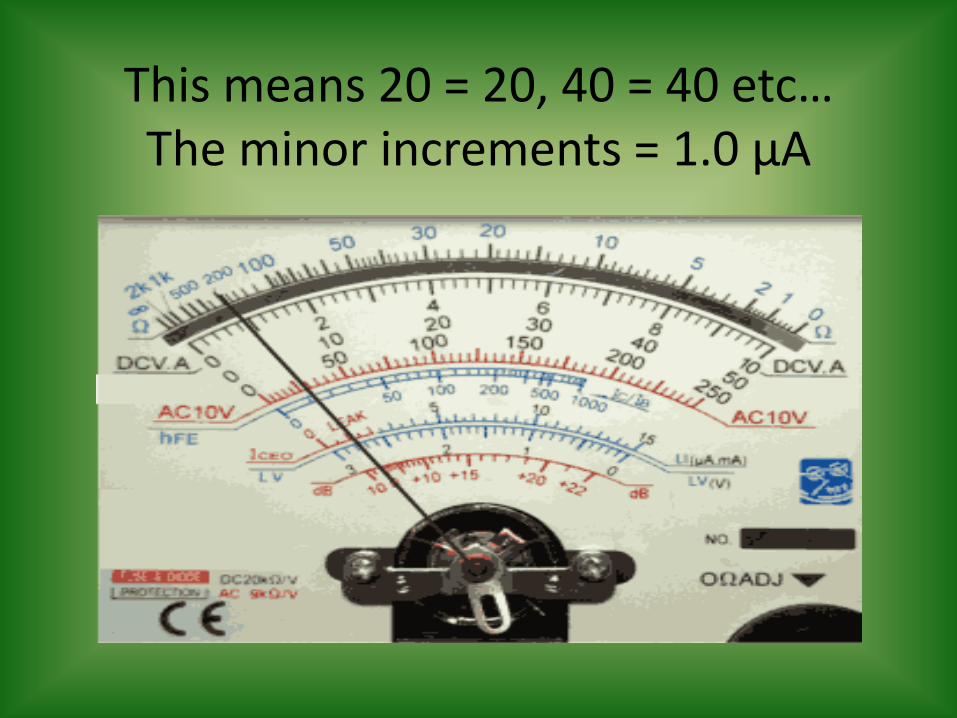
This means 20 = 20, 40 = 40 etc… The minor increments = 1.0 µA
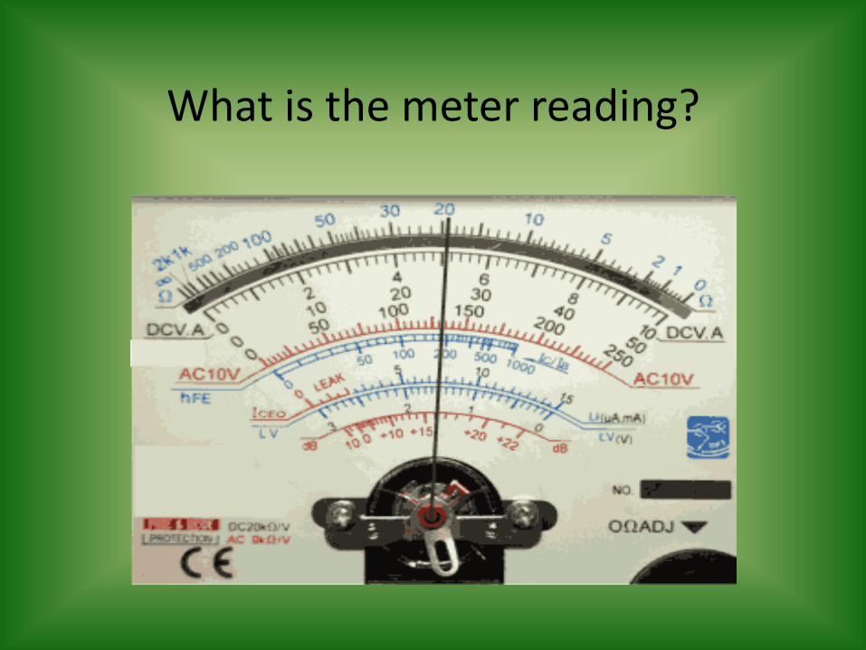
What is the meter reading?
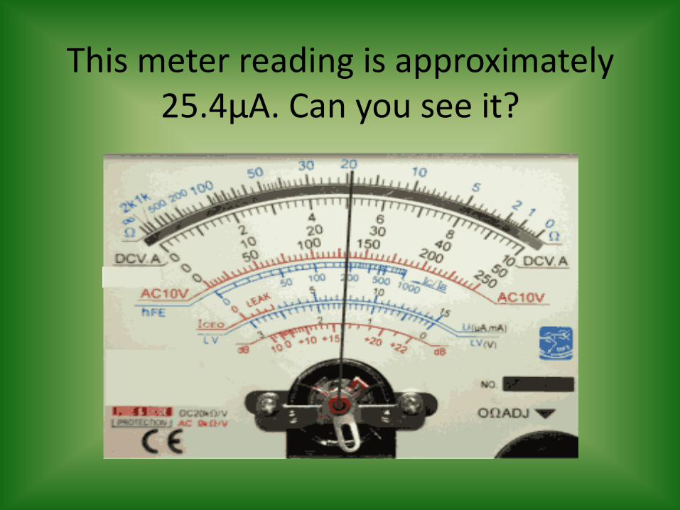
This meter reading is approximately 25.4µA. Can you see it?
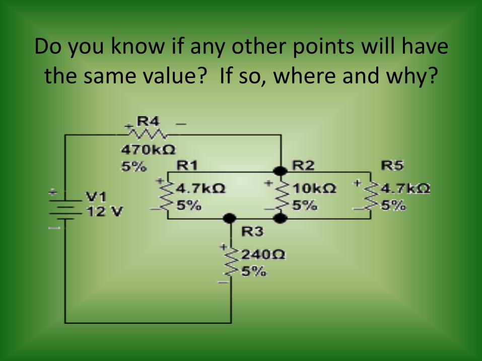
Do you know if any other points will have the same value? If so, where and why?
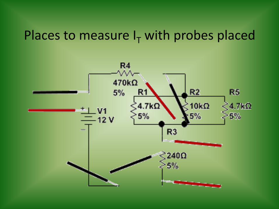
Places to measure IT with probes placed
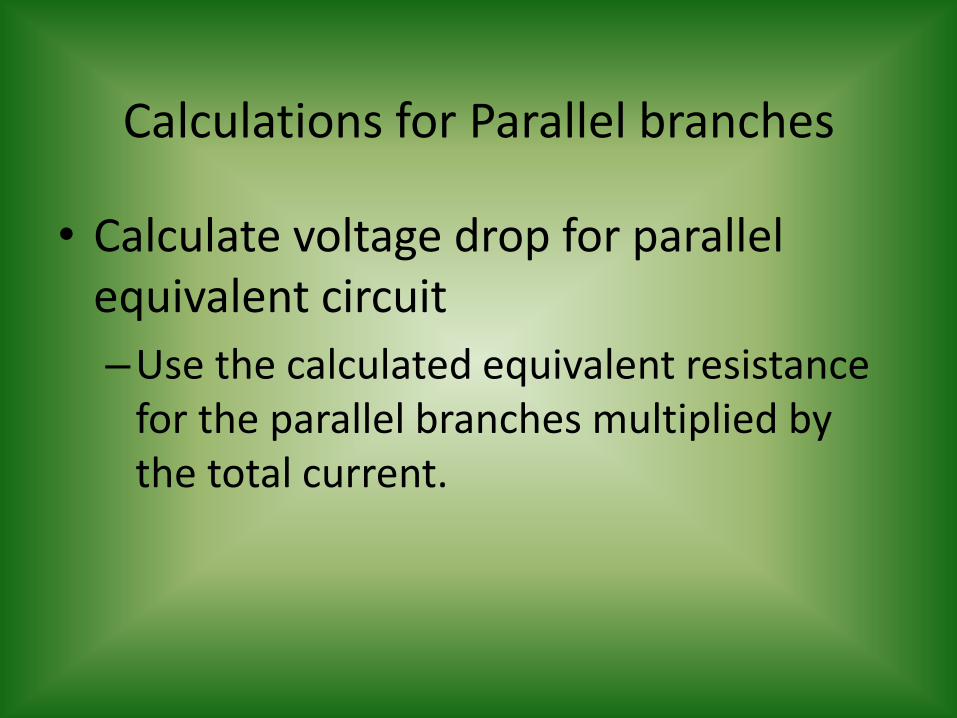
Calculations for Parallel branches
• Calculate voltage drop for parallel equivalent circuit
–Use the calculated equivalent resistance for the parallel branches multiplied by the total current.
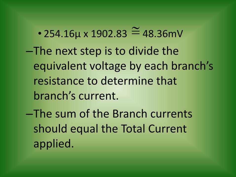
• 254.16µ x 1902.83 48.36mV
–The next step is to divide the equivalent voltage by each branch’s resistance to determine that branch’s current.
–The sum of the Branch currents should equal the Total Current applied.
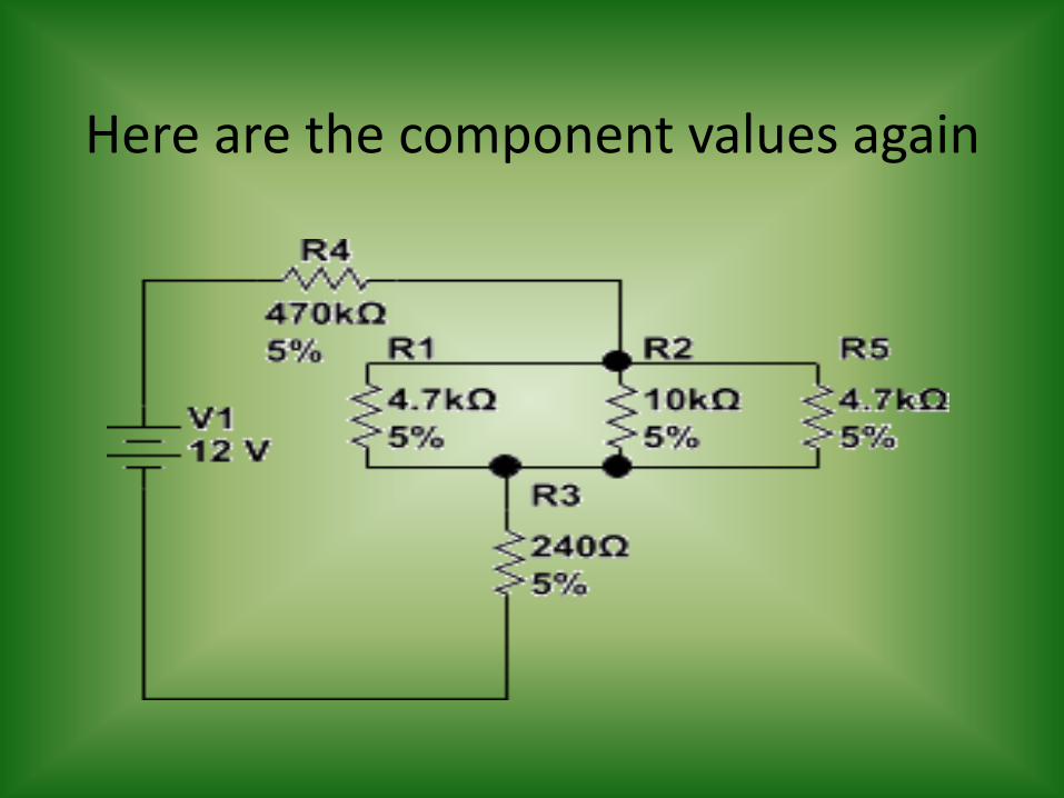
Here are the component values again
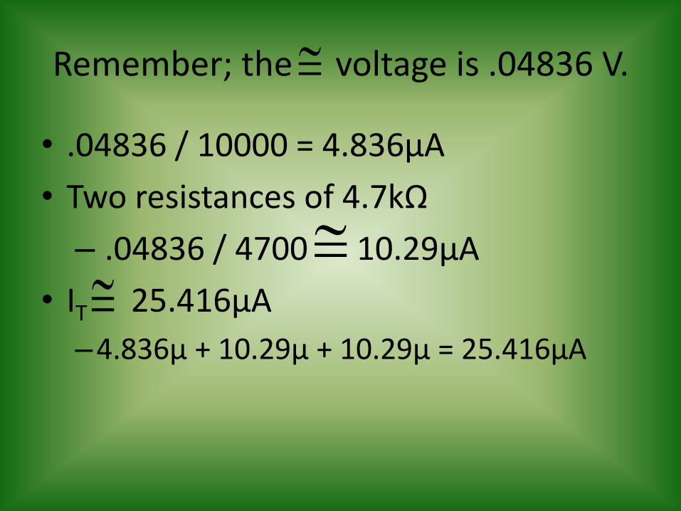
Remember; the voltage is .04836 V.
• .04836 / 10000 = 4.836µA
• Two resistances of 4.7kΩ
– .04836 / 4700 10.29µA
• IT 25.416µA
–4.836µ + 10.29µ + 10.29µ = 25.416µA
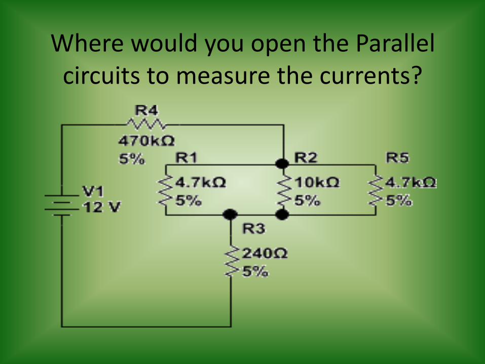
Where would you open the Parallel circuits to measure the currents?
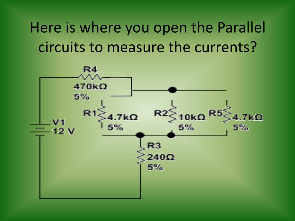
Here is where you open the Parallel circuits to measure the currents?
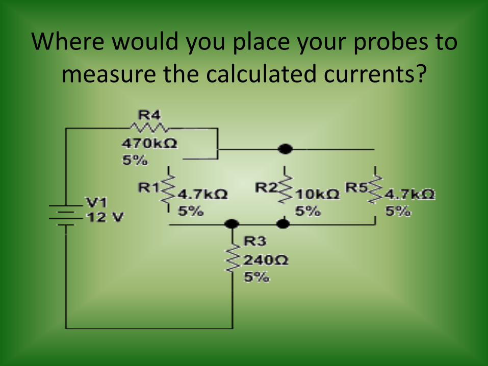
Where would you place your probes to measure the calculated currents?
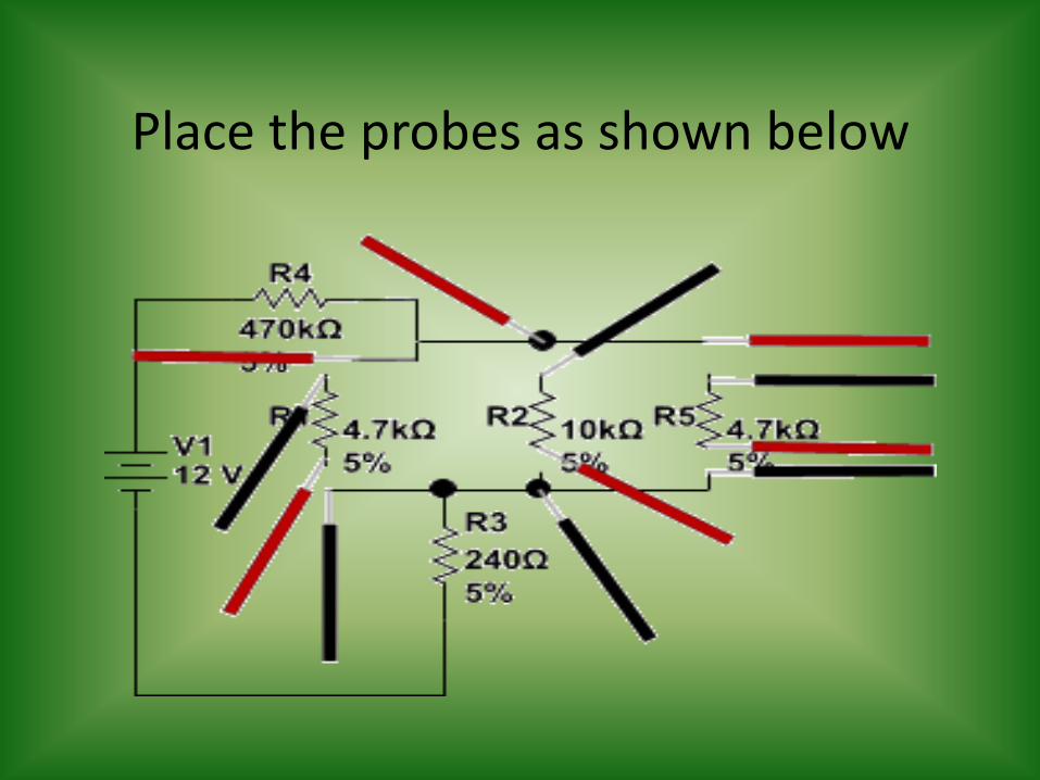
Place the probes as shown below
You calculated less than 50µA
You would use the 50 meter range and this would be the actual range
This means 20 = 20, 40 = 40 etc… The minor increments = 1.0 µA

What is the meter reading?
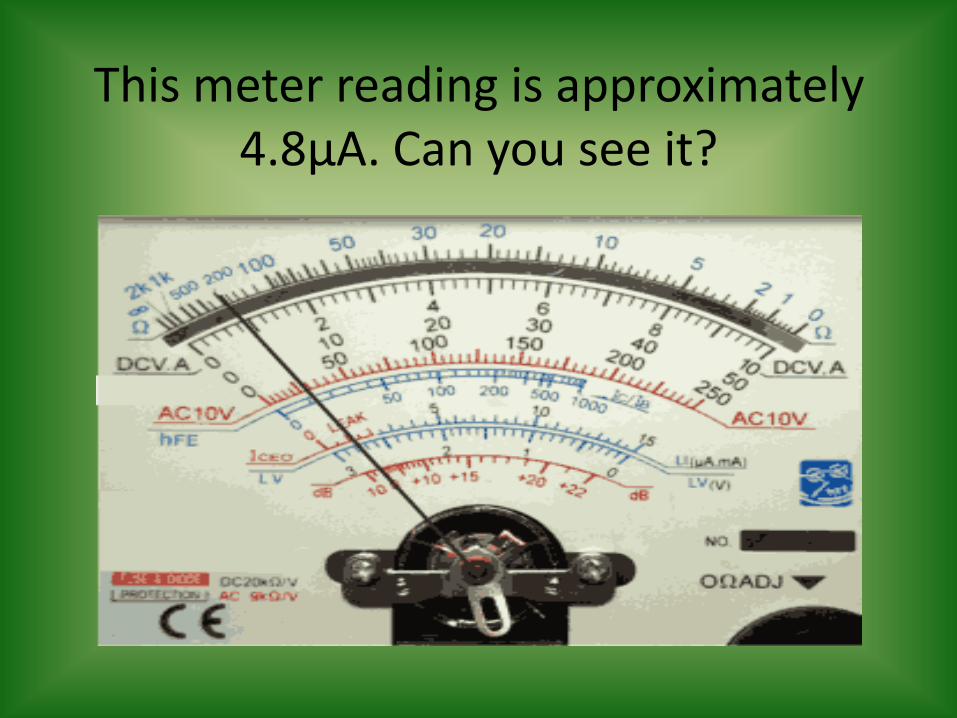
This meter reading is approximately 4.8µA. Can you see it?
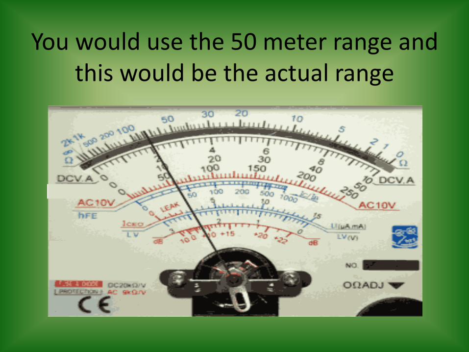
You would use the 50 meter range and this would be the actual range
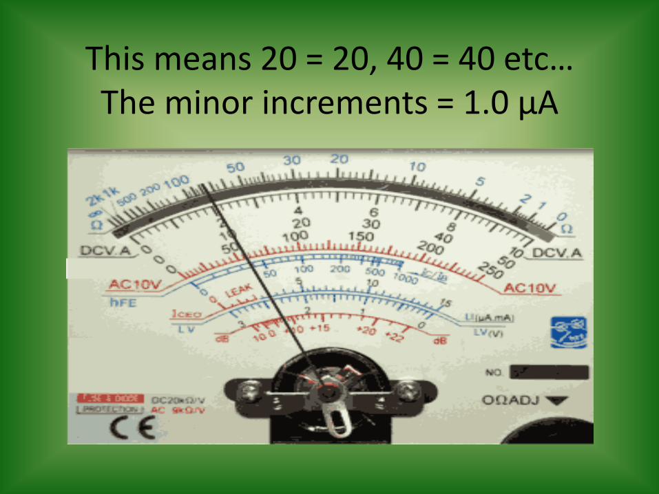
This means 20 = 20, 40 = 40 etc… The minor increments = 1.0 µA
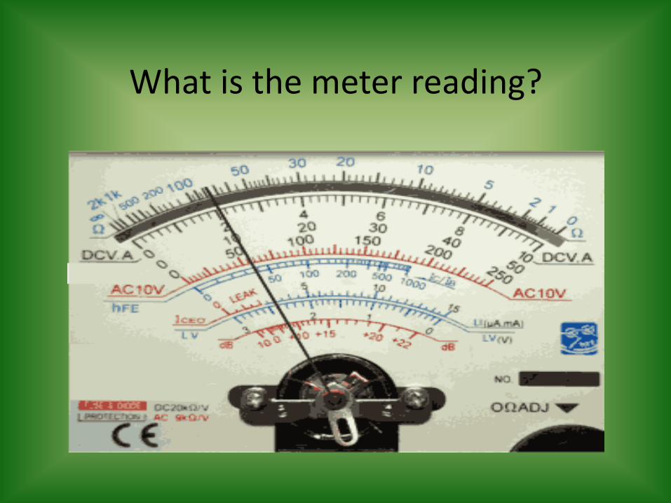
What is the meter reading?
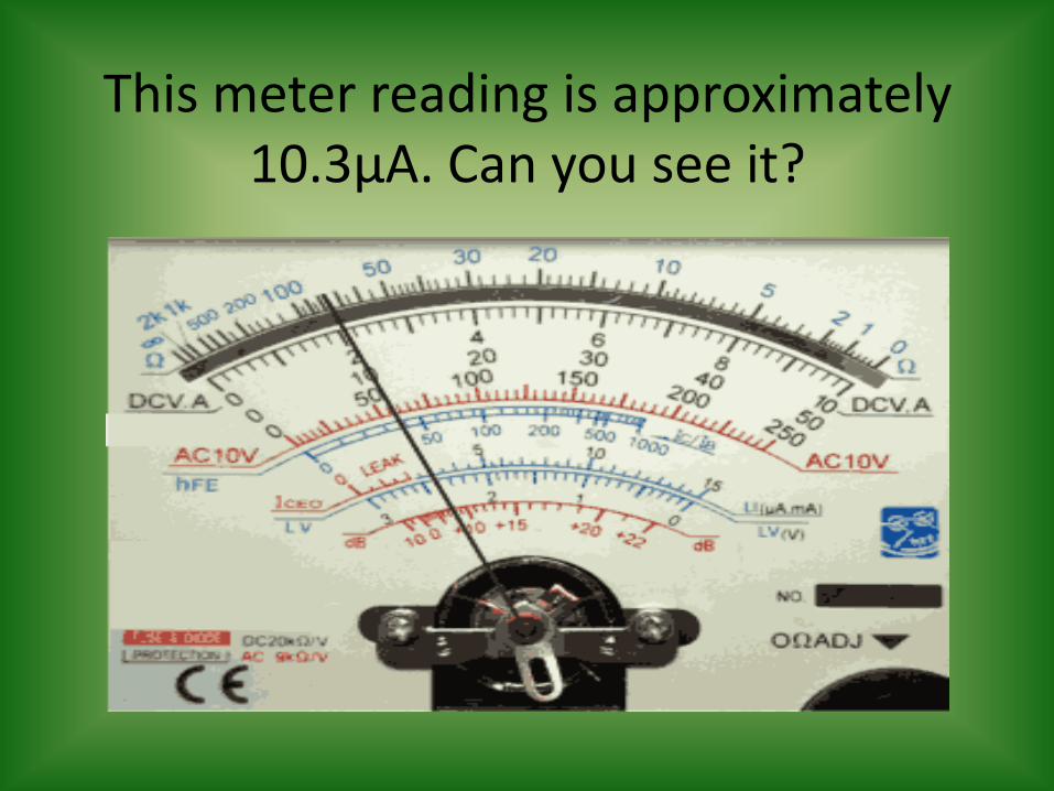
This meter reading is approximately 10.3µA. Can you see it?

Questions?

The End
Developed and Produced by the Instructors in the CIE Instruction
Department. © 10/2011