Embed Size (px)
DESCRIPTION
11
Citation preview
i
Analysis and Design of Multi - Storied (Stilt + G + 4) Residential Building Using STADD Pro. A Project Report submitted in partial fulfillment for the award of degree of
BACHELOR OF TECHNOLOGY IN
CIVIL ENGINEERING Submitted by
P. Anil Kumar (09W61A0137)
N. Sita Gowri Punnaga (09W61A0151) T.Yerranna (09W61A0145)
G. Narayana Rao (09W61A0115) L.Kantarao (09W61A0126)
Under the Esteemed Guidance of
Mr. K. BHANUJI RAO,
Assistant Professor
DEPARTMENT OF CIVIL ENGINEERING
SRI SIVANI COLLEGE OF ENGINEERING, (Affiliated to Jawaharlal Nehru Technological University, Kakinada, A.P)
Chilakapalem Jn., Srikakulam District – 532402.
2009-2013
i
SRI SIVANI COLLEGE OF ENGINEERING DEPARTMENT OF CIVIL ENGINEERING
CERTIFICATE
Certified that this project report titled “Analysis and Design of Multi - Storied
(Stilt + G + 4) Residential Building Using STADD Pro.” is the bonafide work of
P. Anil Kumar (09W61A137), N. Sita Gowri Punnaga (09W61A151), T. Yerranna
(09W61A145), G. Narayana Rao (09W61A0115) and L. Kanta Rao (09W61A126),
who carried out their project work under my supervision. Certified further, that to the best
of my knowledge the work reported herein does not form part of any other project report
or dissertation on the basis of which a degree or award was conferred on an earlier
occasion on this or any other candidate.
INTERNAL GUIDE HEAD OF THE DEPARTMENT Mr. K. Bhanuji Rao, G. Himala Kumari (M.Tech), Assistant Professor, Senior Assistant Professor, Department of Civil, SSCE Department of Civil, SSCE
ii
ABSTRACT
This is a final year Civil project report on Analysis and Design of Multi Storey
(Stilt+G+4) Residential Building using STAAD.Pro The present project deals with the
analysis of a multi storied residential building of Stilt+G+4 consisting of 4 flats in
each floor. This project is mostly based on software and it is essential to know the details
about these software’s. The software’s used in this project are STAAD.Pro (v8i) & Auto
cad.
The principle objective of this project is to analyze and design a multi-storied
building [Stilt+G+4] using STAAD.Pro. The design involves load calculations manually
and analyzing the whole structure by STAAD Pro. The design methods used in
STAAD.Pro analysis are Limit State Design conforming to Indian Standard Code of
Practice. STAAD.Pro features a state-of-the-art user interface, visualization tools,
powerful analysis and design engines with advanced finite element and dynamic analysis
capabilities. From model generation, analysis and design to visualization and result
verification, STAAD.Pro is the professional’s choice.
STAAD.Pro has a very interactive user interface which allows the users to draw the
frame and input the load values and dimensions. Then according to the specified criteria
assigned it analyses the structure and designs the members with reinforcement details for
RCC frames. We continued with our work with some more multi-storied frames under
various load combinations. Our final work was the proper analysis and design of a [Stilt
+ G + 4] RCC frame under various load combinations.
We considered a RCC frame with the dimensions as per client requirements both
in x-axis and z-axis. The y-axis consisted of Stilt+G+4 floors. The total numbers of
beams in each floor were 97 and the numbers of columns were 24. The height of each floor
is 3m. The structure was subjected to self weight, dead load, live load, wind load and
seismic loads under the load case details of STAAD.Pro. The wind load values were
generated by STAAD.Pro considering the given wind intensities at different heights and
iii
strictly abiding by the specifications of IS: 875. Seismic load calculations were done
following IS: 1893-2002. The materials were specified and cross-sections of the beam and
column members were assigned. The supports at the base of the structure were also
specified as fixed.
The codes of practice to be followed were also specified for design purpose
with other important details. Then STAAD.Pro was used to analyze the structure and
design the members. In the post-processing mode, after completion of the design, we
can work on the structure and study the bending moment and shear force values with
the generated diagrams. We may also check the deflection of various members under the
given loading combinations. The design of the building is dependent upon the
minimum requirements as prescribed in the Indian Standard Codes.
In order to compete in the ever growing competent market it is very important for
a structural engineer to save time. Complicated and high-rise structures need very time
taking and cumbersome calculations using conventional manual methods. So, the
STAAD.Pro software provides us a fast, efficient, easy to use and accurate platform for
analyzing and designing structures.

iv
ACKNOWLEDGEMENT
The satisfaction that accompanies the successful completion of any task would be
incomplete without the mention of people who made it possible and whose constant
guidance and encouragement crown all the efforts with success.
First and foremost, I thank to my project guide Sri. K. Bhanuji Rao, Assistant
Professor, Department of Civil Engineering for giving me an opportunity to work on this
challenging topic and providing me guidance and also I would like to thank our external
project guide Sri. V. Madhusudhana Rao, (VMR Structural Consultancy,
Visakhapatnam) for his tremendous source of inspiration, invaluable guidance,
encouragement and suggestions in completion of our project.
I feel elated to extend my floral gratitude to Smt. G. Himala Kumari, Senior
Assistant Professor and Head of Department of Civil Engineering, for her encouragement
all the way during analysis of the project. Her annotations, insinuations and criticisms are
the key behind the successful completion of doing the thesis and for providing me all the
required facilities.
I would like to take this opportunity to express my profound sense of gratitude to
revered Principal Dr. Joshua V. J. P (M.E) for giving me the opportunity of doing thesis
and for providing me all the required facilities.
I also take this opportunity to express my heartfelt thanks to the teaching and non
teaching staff of the department, for their perspective comments and suggestions.
P.Anil Kumar (09W61A0137),
N.Sita Gowri Punnaga (09W61A0151),
L.Kanta Rao (09W61A0126),
G.Narayanarao (09W61A0115),
T.Yerranna (09W61A0145).
v
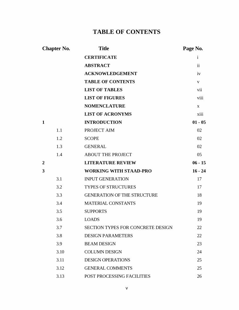
TABLE OF CONTENTS
Chapter No. Title Page No. CERTIFICATE i
ABSTRACT ii
ACKNOWLEDGEMENT iv
TABLE OF CONTENTS v
LIST OF TABLES vii
LIST OF FIGURES viii
NOMENCLATURE x
LIST OF ACRONYMS xiii
1 INTRODUCTION 01 - 05
1.1 PROJECT AIM 02
1.2 SCOPE 02
1.3 GENERAL 02
1.4 ABOUT THE PROJECT 05
2 LITERATURE REVIEW 06 - 15
3 WORKING WITH STAAD-PRO 16 - 24
3.1 INPUT GENERATION 17
3.2 TYPES OF STRUCTURES 17
3.3 GENERATION OF THE STRUCTURE 18
3.4 MATERIAL CONSTANTS 19
3.5 SUPPORTS 19
3.6 LOADS 19
3.7 SECTION TYPES FOR CONCRETE DESIGN 22
3.8 DESIGN PARAMETERS 22
3.9 BEAM DESIGN 23
3.10 COLUMN DESIGN 24
3.11 DESIGN OPERATIONS 25
3.12 GENERAL COMMENTS 25
3.13 POST PROCESSING FACILITIES 26
vi
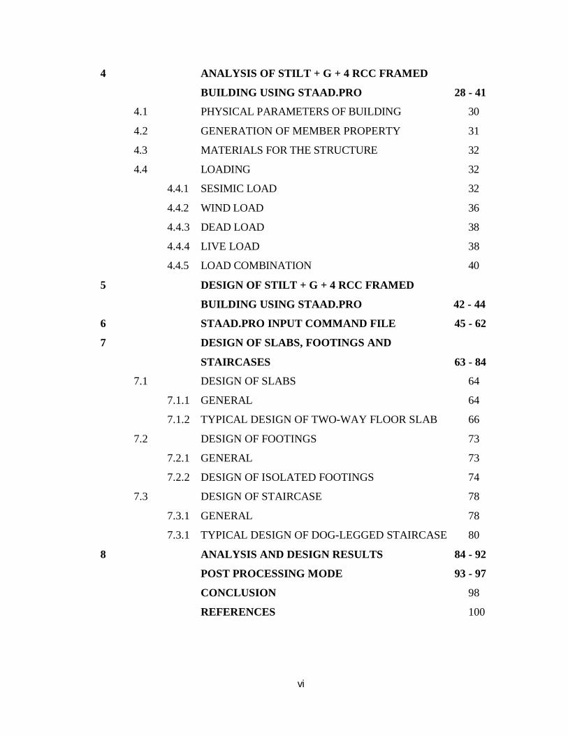
4 ANALYSIS OF STILT + G + 4 RCC FRAMED
BUILDING USING STAAD.PRO 28 - 41
4.1 PHYSICAL PARAMETERS OF BUILDING 30
4.2 GENERATION OF MEMBER PROPERTY 31
4.3 MATERIALS FOR THE STRUCTURE 32
4.4 LOADING 32
4.4.1 SESIMIC LOAD 32
4.4.2 WIND LOAD 36
4.4.3 DEAD LOAD 38
4.4.4 LIVE LOAD 38
4.4.5 LOAD COMBINATION 40
5 DESIGN OF STILT + G + 4 RCC FRAMED
BUILDING USING STAAD.PRO 42 - 44
6 STAAD.PRO INPUT COMMAND FILE 45 - 62
7 DESIGN OF SLABS, FOOTINGS AND
STAIRCASES 63 - 84
7.1 DESIGN OF SLABS 64
7.1.1 GENERAL 64
7.1.2 TYPICAL DESIGN OF TWO-WAY FLOOR SLAB 66
7.2 DESIGN OF FOOTINGS 73
7.2.1 GENERAL 73
7.2.2 DESIGN OF ISOLATED FOOTINGS 74
7.3 DESIGN OF STAIRCASE 78
7.3.1 GENERAL 78
7.3.1 TYPICAL DESIGN OF DOG-LEGGED STAIRCASE 80
8 ANALYSIS AND DESIGN RESULTS 84 - 92
POST PROCESSING MODE 93 - 97
CONCLUSION 98
REFERENCES 100
vii
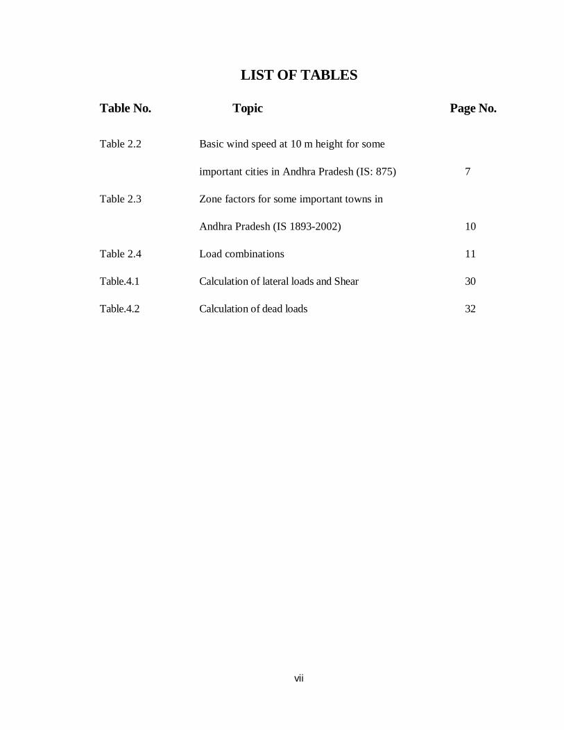
LIST OF TABLES
Table No. Topic Page No.
Table 2.2 Basic wind speed at 10 m height for some
important cities in Andhra Pradesh (IS: 875) 7
Table 2.3 Zone factors for some important towns in
Andhra Pradesh (IS 1893-2002) 10
Table 2.4 Load combinations 11
Table.4.1 Calculation of lateral loads and Shear 30
Table.4.2 Calculation of dead loads 32
viii
LIST OF FIGURES
Fig No. Title Page No. Fig.3.1 STAAD input file 14
Fig.3.2 Generation of structure through GUI 15
Fig.3.3 Member load configuration 17
Fig.4.1 Plan of the Stilt+G+4 Storey Building 25
Fig.4.2 Elevation of the Stilt+G+4 Storey Building 26
Fig 4.3 Input window for Generation of member property 27
Fig. 4.4 Fixing supports of the structure 28
Fig. 4.5 STAAD utilizes the following procedure to generate
the lateral seismic loads 29
Fig.4.6 Bending moment and Shear force 32
Fig.4.7 STAAD utilizes the following procedure to generate the
lateral seismic loads 33
Fig.4.8 Window showing wind load in +ve Z-direction 33
Fig.4.9 The structure elevation under live load 35
Fig.4.10 The plan of the structure under live load 35
Fig.4.11 GUI showing Auto Load Combination with Indian Code 36
Fig.4.12 GUI showing the analyzing window 37
Fig.5.1 Input Windows for Design Purpose 38
Fig.5.2 Design Specifications in STAAD.Pro 39
Fig.7.1 One way slab 58
Fig.7.2 Two - way slab 58
Fig.7.3 Details of Dog-Legged Staircase 70
Fig.8.1 Geometry of beam no. 84 78
Fig.8.2 Property of beam no. 84 78
Fig.8.3 Shear bending of beam no. 84 79
Fig.8.4 Deflection of beam no. 84 79
ix
Fig No. Title Page No.
Fig.8.5 Geometry of beam no. 105 81
Fig.8.6 Property of beam no. 105 81
Fig.8.7 Shear bending of beam no. 105 82
Fig.8.8 Deflection of beam no. 105 82
Fig.8.9 Cross-Section of the column no. 9 83
Fig.8.10 Cross-section of the column no. 24 84
Fig.8.11 Post processing mode in STAAD.Pro 85
Fig.8.12 Bending in Z 85
Fig.8.13 Shear stress at any section 86
Fig.8.14 Graph for shear force and bending moment for a beam 86
Fig.8.15 Graph for shear force and bending moment for a column 87
x
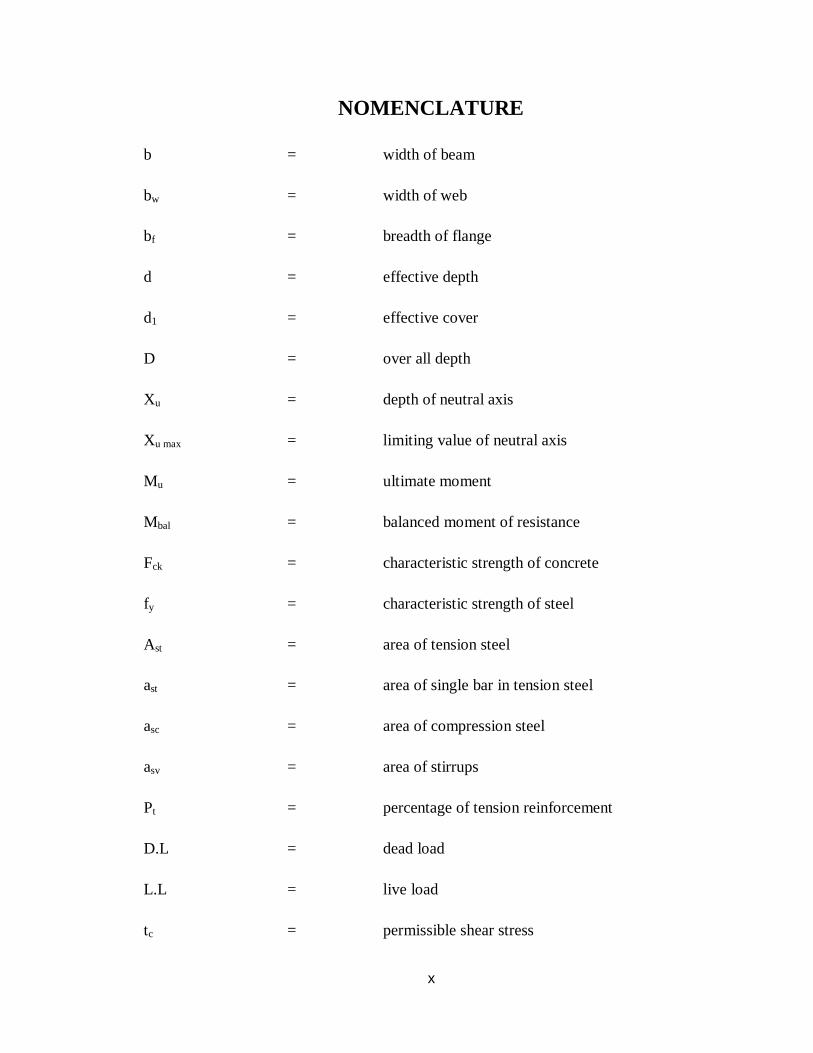
NOMENCLATURE
b = width of beam
bw = width of web
bf = breadth of flange
d = effective depth
d1 = effective cover
D = over all depth
Xu = depth of neutral axis
Xu max = limiting value of neutral axis
Mu = ultimate moment
Mbal = balanced moment of resistance
Fck = characteristic strength of concrete
fy = characteristic strength of steel
Ast = area of tension steel
ast = area of single bar in tension steel
asc = area of compression steel
asv = area of stirrups
Pt = percentage of tension reinforcement
D.L = dead load
L.L = live load
tc = permissible shear stress
xi
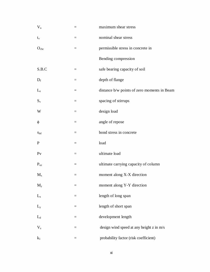
Vu = maximum shear stress
tv = nominal shear stress
Ocbc = permissible stress in concrete in
Bending compression
S.B.C = safe bearing capacity of soil
Df = depth of flange
Le = distance b/w points of zero moments in Beam
Sv = spacing of stirrups
W = design load
ϕ = angle of repose
τbd = bond stress in concrete
P = load
Pv = ultimate load
Puz = ultimate carrying capacity of column
Mx = moment along X-X direction
My = moment along Y-Y direction
Lx = length of long span
Ly = length of short span
Ld = development length
Vz = design wind speed at any height z in m/s
k1 = probability factor (risk coefficient)
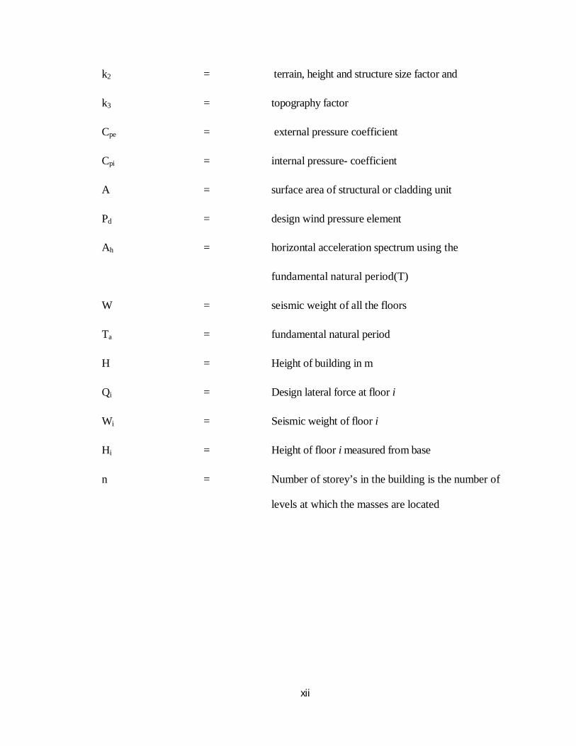
xii
k2 = terrain, height and structure size factor and
k3 = topography factor
Cpe = external pressure coefficient
Cpi = internal pressure- coefficient
A = surface area of structural or cladding unit
Pd = design wind pressure element
Ah = horizontal acceleration spectrum using the
fundamental natural period(T)
W = seismic weight of all the floors
Ta = fundamental natural period
H = Height of building in m
Qi = Design lateral force at floor i
Wi = Seismic weight of floor i
Hi = Height of floor i measured from base
n = Number of storey’s in the building is the number of
levels at which the masses are located

xiii
LIST OF ACRONYMS
STAAD Structural Aided and Designing
API Application Program Interface
ATL Active Template Library
COM Component Object Model
FTP File Transfer Protocol
GUI Graphical User Interface
HTTP Hypertext Transfer Protocol
IDE Integrated Development Environment
I/O Input/output
URL Uniform Resource Locator
VB Visual Basic
VBA Visual Basic for Applications.

1
CHAPTER - 1
INTRODUCTION
2
CHAPTER – 1
INTRODUCTION
1.1. Project Aim:
To analyze and design a multi-storied building for the usage of residential purpose
using STAAD PRO and manual calculations.
1.2. Scope:
The main scope of this project is to apply class room knowledge in the real world
by designing a multi-storied residential building. These building require large and clear
areas unobstructed by the columns. The large floor area provides sufficient flexibility and
facility for later change in the production layout without major building alterations. The
residential buildings are constructed with adequate headroom for the use of an overhead
traveling crane.
1.3 General:
STAAD Pro. V8i is the most popular structural engineering software product for
model generation, analysis and multi-material design. It has an intuitive, user-friendly
GUI, visualization tools, powerful analysis and design facilities and seamless integration
to several other modeling and design software products. The software is fully compatible
with all Windows operating systems but is optimized for Windows XP.
The ultimate power tool for Computerized Structural Engineering
For static or dynamic analysis of bridges, containment structures, embedded structures
(tunnels and culverts), pipe racks, steel, concrete, aluminum or timber buildings,
transmission towers, stadiums or any other simple or complex structure, STAAD Pro. has
been the choice of design professionals around the world for their specific analysis needs.
Our project involves analysis and design of multi-storied [Stilt + G + 4] using a very
popular designing software STAAD Pro (V8i).
3
We have chosen STAAD Pro because of its following advantages:
easy to use interface,
conformation with the Indian Standard Codes,
versatile nature of solving any type of problem,
Accuracy of the solution.
STAAD.Pro consists of the following:
The STAAD.Pro Graphical User Interface: It is used to generate the model, which can
then be analyzed using the STAAD engine. After analysis and design is completed, the
GUI can also be used to view the results graphically.
The STAAD analysis and design engine: It is a general-purpose calculation engine
for structural analysis and integrated Steel, Concrete, Timber and Aluminium design.
To start with we have solved some sample problems using STAAD Pro and checked the
accuracy of the results with manual calculations. The results were to satisfaction and
were accurate. In the initial phase of our project we have done calculations regarding
loadings on buildings and also considered seismic and wind loads.
Structural analysis comprises the set of physical laws and mathematics required to study
and predicts the behavior of structures. Structural analysis can be viewed more abstractly
as a method to drive the engineering design process or prove the soundness of a design
without a dependence on directly testing it.
To perform an accurate analysis a structural engineer must determine such information as
structural loads, geometry, support conditions, and materials properties. The results of
such an analysis typically include support reactions, stresses and displacements. This
information is then compared to criteria that indicate the conditions of failure. Advanced
structural analysis may examine dynamic response, stability and non-linear behavior. The
aim of design is the achievement of an acceptable probability that structures being
designed will perform satisfactorily during their intended life. With an appropriate degree

4
of safety, they should sustain all the loads and deformations of normal construction and
use and have adequate durability and adequate resistance to the effects of seismic and
wind. Structure and structural elements shall normally be designed by Limit State
Method. Account should be taken of accepted theories, experiment and experience and
the need to design for durability.
Design, including design for durability, construction and use in service should be
considered as a whole. The realization of design objectives requires compliance with
clearly defined standards for materials, production, workmanship and also maintenance
and use of structure in service.
The design of the building is dependent upon the minimum requirements as prescribed in
the Indian Standard Codes. The minimum requirements pertaining to the structural
safety of buildings are being covered by way of laying down minimum design loads
which have to be assumed for dead loads, imposed loads, and other external loads, the
structure would be required to bear. Strict conformity to loading standards
recommended in this code, it is hoped, will not only ensure the structural safety of the
buildings which are being designed.
5
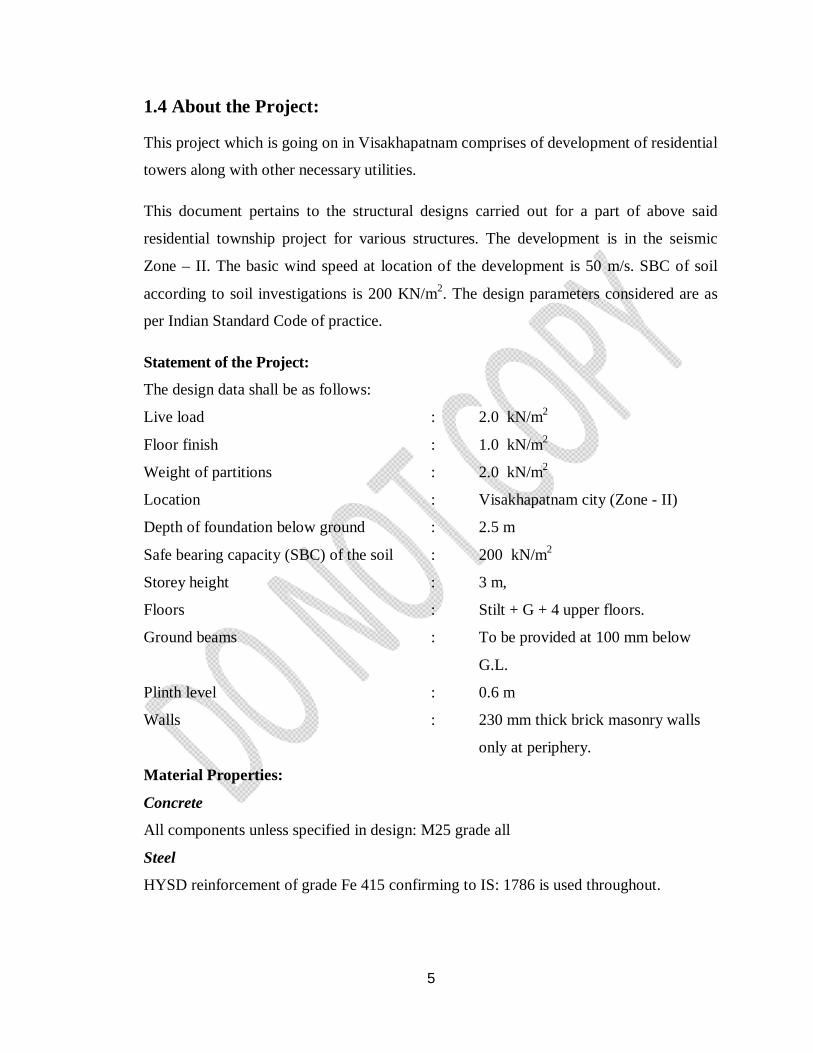
1.4 About the Project:
This project which is going on in Visakhapatnam comprises of development of residential
towers along with other necessary utilities.
This document pertains to the structural designs carried out for a part of above said
residential township project for various structures. The development is in the seismic
Zone – II. The basic wind speed at location of the development is 50 m/s. SBC of soil
according to soil investigations is 200 KN/m2. The design parameters considered are as
per Indian Standard Code of practice.
Statement of the Project:
The design data shall be as follows:
Live load : 2.0 kN/m2
Floor finish : 1.0 kN/m2
Weight of partitions : 2.0 kN/m2
Location : Visakhapatnam city (Zone - II)
Depth of foundation below ground : 2.5 m
Safe bearing capacity (SBC) of the soil : 200 kN/m2
Storey height : 3 m,
Floors : Stilt + G + 4 upper floors.
Ground beams : To be provided at 100 mm below
G.L.
Plinth level : 0.6 m
Walls : 230 mm thick brick masonry walls
only at periphery.
Material Properties:
Concrete
All components unless specified in design: M25 grade all
Steel
HYSD reinforcement of grade Fe 415 confirming to IS: 1786 is used throughout.

6
CHAPTER - 2
LITERATURE REVIEW
7
CHAPTER - 2
LITERATURE REVIEW
IS: 875 (Part 1) – 1987 for Dead Loads, Indian Standard Code Of Practice For Design
Loads (Other Than Earthquake) For Buildings and Structures, All permanent
constructions of the structure form the dead loads. The dead load comprises of the
weights of walls, partitions floor finishes, false ceilings, false floors and the other
permanent constructions in the buildings. The dead load loads may be calculated from the
dimensions of various members and their unit weights. The unit weights of plain concrete
and reinforced concrete made with sand and gravel or crushed natural stone aggregate
may be taken as 24 KN/m3 and 24 KN/m3respectively.
IS: 875 (Part 2) – 1987 for Imposed Loads, Indian Standard Code Of Practice For
Design Loads (Other Than Earthquake), For Buildings And Structures, Imposed load is
produced by the intended use or occupancy of a building including the weight of movable
partitions, distributed and concentrated loads, load due to impact and vibration and dust
loads. Imposed loads do not include loads due to wind, seismic activity, snow, and loads
imposed due to temperature changes to which the structure will be subjected to, creep and
shrinkage of the structure, the differential settlements to which the structure may
undergo.
IS: 875 (Part 3) – 1987 for Wind Loads, Indian Standard Code Of Practice For Design
Loads (Other Than Earthquake) For Buildings And Structures, This standard gives wind
forces and their effects ( static and dynamic ) that should that taken into account when
designing buildings, structures and components thereof. Wind is air in motion relative to
the surface of the earth. The primary cause of wind is traced to earth’s rotation and
differences in terrestrial radiation. The radiation effects are primarily responsible for
convection either upwards or downwards. The wind generally blows horizontal to the
ground at high wind speeds. Since vertical components of atmospheric motion are
relatively small, the term ‘wind’ denotes almost exclusively the horizontal wind, vertical
winds are always identified as such. The wind speeds are assessed with the aid of
8
anemometers or anemographs which are installed at meteorological observatories at heights
generally varying from 10 to 30 meters above ground.
Design Wind Speed (Vz): The basic wind speed (Vb) for any site shall be obtained from and
shall be modified to include the following effects to get design wind velocity at any height
(Vz) for the chosen structure:
a) Risk level;
b) Terrain roughness, height and size of structure; and
c) Local topography.
It can be mathematically expressed as follows:
Vz = Vb * k1 * k2* k3
Where:
Vz = design wind speed at any height z in m/s;
k1 = probability factor (risk coefficient)
k2 = terrain, height and structure size factor and
k3 = topography factor
Risk Coefficient (k1 Factor) – It gives basic wind speeds for terrain Category 2 as
applicable at 10 m above ground level based on 50 years mean return period. In the design
of all buildings and structures, a regional basic wind speed having a mean return period of
50 years shall be used.
Terrain, Height and Structure Size Factor (k2 Factor) – Terrain - Selection of terrain
categories shall be made with due regard to the effect of obstructions which constitute
the ground surface roughness. The terrain category used in the design of a structure may
vary depending on the direction of wind under consideration. Wherever sufficient
meteorological information is available about the nature of wind direction, the
orientation of any building or structure may be suitably planned.
9
Topography (k3 Factor) – The basic wind speed Vb takes account of the general level of
site above sea level. This does not allow for local topographic features such as hills,
valleys, cliffs, escarpments, or ridges which can significantly affect wind speed in their
vicinity. The effect of topography is to accelerate wind near the summits of hills or
crests of cliffs, escarpments or ridges and decelerate the wind in valleys or near the
foot of cliff, steep escarpments, or ridges.
WIND PRESSURES AND FORCES ON BUILDINGS/STRUCTURES:
General:
The wind load on a building shall be calculated for:
a) The building as a whole,
b) Individual structural elements as roofs and walls, and
c) Individual cladding units including glazing and their fixings
Pressure Coefficients - The pressure coefficients are always given for a particular surface
or part of the surface of a building. The wind load acting normal to a surface is obtained
by multiplying the area of that surface or its appropriate portion by the pressure coefficient
(Cp) and the design wind pressure at the height of the surface from the ground. The average
values of these pressure coefficients for some building shapes. Average values of pressure
coefficients are given for critical wind directions in one or more quadrants. In order
to determine the maximum wind load on the building, the total load should be calculated
for each of the critical directions shown from all quadrants. Where considerable
variation of pressure occurs over a surface, it has been subdivided and mean pressure
coefficients given for each of its several parts.
Wind Load on Individual Members – When calculating the wind load on individual
structural elements such as roofs and walls, and individual cladding units and their
fittings, it is essential to take account of the pressure difference between opposite faces of
such elements or units. For clad structures, it is, therefore, necessary to know the internal
pressure as well as the external pressure. Then the wind load, F, acting in a direction
normal to the individual structural element or cladding unit is:
10
F = (Cpe - Cpi) A Pd Where,
Cpe = external pressure coefficient,
Cpi = internal pressure- coefficient,
A = surface area of structural or cladding unit, and
Pd = design wind pressure element.
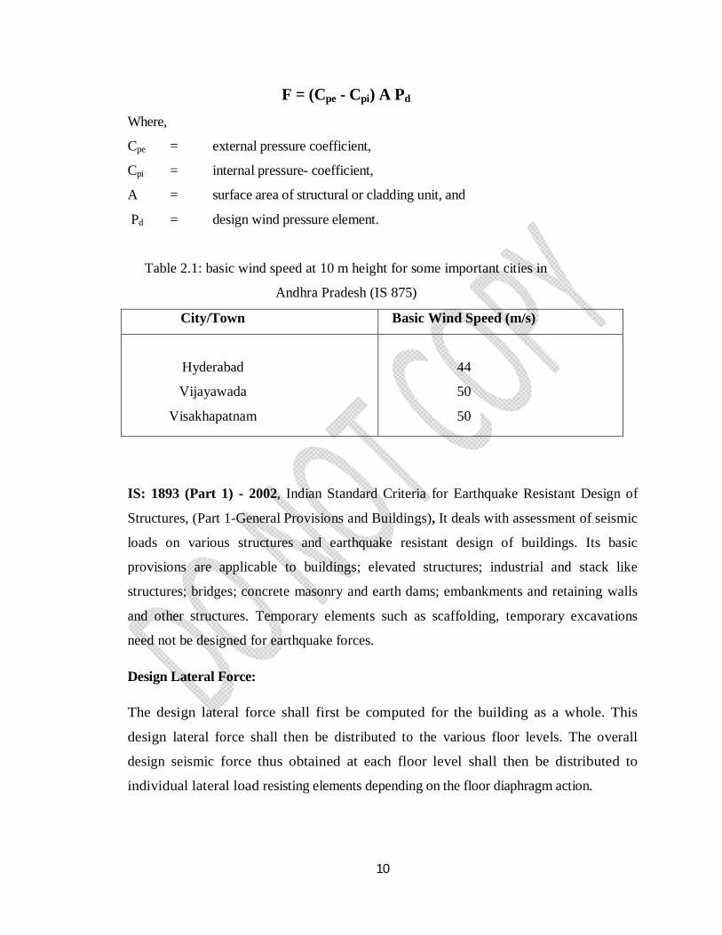
Table 2.1: basic wind speed at 10 m height for some important cities in
Andhra Pradesh (IS 875)
City/Town Basic Wind Speed (m/s)
Hyderabad
Vijayawada
Visakhapatnam
44
50
50
IS: 1893 (Part 1) - 2002, Indian Standard Criteria for Earthquake Resistant Design of
Structures, (Part 1-General Provisions and Buildings), It deals with assessment of seismic
loads on various structures and earthquake resistant design of buildings. Its basic
provisions are applicable to buildings; elevated structures; industrial and stack like
structures; bridges; concrete masonry and earth dams; embankments and retaining walls
and other structures. Temporary elements such as scaffolding, temporary excavations
need not be designed for earthquake forces.
Design Lateral Force:
The design lateral force shall first be computed for the building as a whole. This
design lateral force shall then be distributed to the various floor levels. The overall
design seismic force thus obtained at each floor level shall then be distributed to
individual lateral load resisting elements depending on the floor diaphragm action.
11
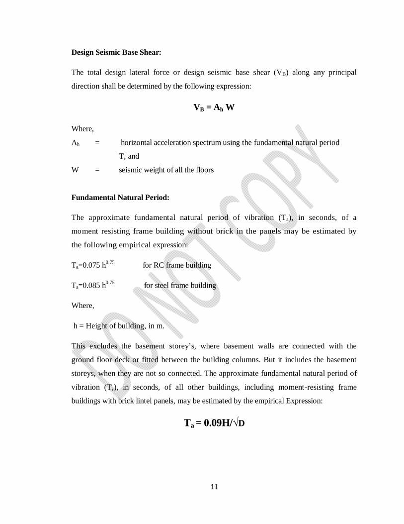
Design Seismic Base Shear:
The total design lateral force or design seismic base shear (VB) along any principal
direction shall be determined by the following expression:
VB = Ah W
Where,
Ah = horizontal acceleration spectrum using the fundamental natural period
T, and
W = seismic weight of all the floors
Fundamental Natural Period:
The approximate fundamental natural period of vibration (Ta), in seconds, of a
moment resisting frame building without brick in the panels may be estimated by
the following empirical expression:
Ta=0.075 h0.75 for RC frame building
Ta=0.085 h0.75 for steel frame building
Where,
h = Height of building, in m.
This excludes the basement storey’s, where basement walls are connected with the
ground floor deck or fitted between the building columns. But it includes the basement
storeys, when they are not so connected. The approximate fundamental natural period of
vibration (T,), in seconds, of all other buildings, including moment-resisting frame
buildings with brick lintel panels, may be estimated by the empirical Expression:
Ta = 0.09H/√D
12
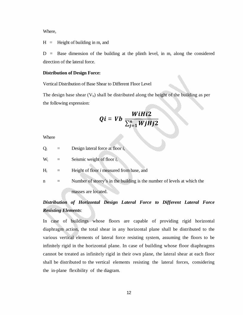
Where,
H = Height of building in m, and
D = Base dimension of the building at the plinth level, in m, along the considered
direction of the lateral force.
Distribution of Design Force:
Vertical Distribution of Base Shear to Different Floor Level
The design base shear (Vb) shall be distributed along the height of the building as per
the following expression:
푸풊 = 푽풃 푾풊푯풊ퟐ
∑ 푾풋푯풋ퟐ풏풋 ퟏ
Where
Qi = Design lateral force at floor i,
Wi = Seismic weight of floor i,
Hi = Height of floor i measured from base, and
n = Number of storey’s in the building is the number of levels at which the
masses are located.
Distribution of Horizontal Design Lateral Force to Different Lateral Force
Resisting Elements:
In case of buildings whose floors are capable of providing rigid horizontal
diaphragm action, the total shear in any horizontal plane shall be distributed to the
various vertical elements of lateral force resisting system, assuming the floors to be
infinitely rigid in the horizontal plane. In case of building whose floor diaphragms
cannot be treated as infinitely rigid in their own plane, the lateral shear at each floor
shall be distributed to the vertical elements resisting the lateral forces, considering
the in-plane flexibility of the diagram.
13
Dynamic Analysis-
Dynamic analysis shall be performed to obtain the design seismic force, and its distribution
to different levels along the height of the building and to the various lateral load
resisting elements, for the following Buildings:
a) Regular buildings -Those greater than 40 m in height in Zones IV and V and those
Greater than 90 m in height in Zones II and III.
b) Irregular buildings - All framed buildings higher than 12m in Zones IV and V and
those greater than 40m in height in Zones II and III.
The analytical model for dynamic analysis of buildings with unusual configuration should
be such that it adequately models the types of irregularities present in the building
configuration. Buildings with plan irregularities cannot be modeled for dynamic analysis.
Note: For irregular buildings, lesser than 40 m in height in Zones II and III, dynamic
analysis, even though not mandatory, is recommended.
Dynamic analysis may be performed either by the Time History Method or by the
Response Spectrum Method. However, in either method, the design base shear (VB) shall be
compared with a base shear (VB) calculated using a fundamental period Ta.
Time History Method: Time history method of analysis shall be based on an appropriate
ground motion and shall be performed using accepted principles of dynamics.
Response Spectrum Method: Response spectrum method of analysis shall be
performed using the design spectrum specified, or by a site-specific design spectrum
mentioned.
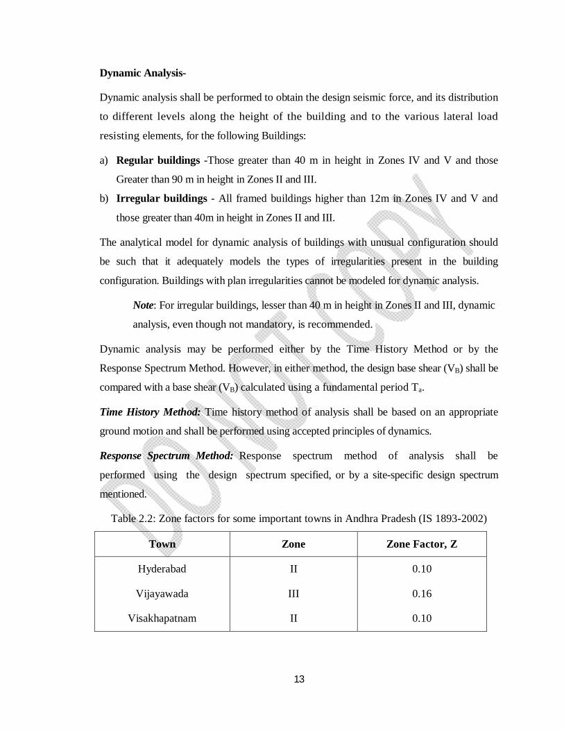
Table 2.2: Zone factors for some important towns in Andhra Pradesh (IS 1893-2002)
Town Zone Zone Factor, Z
Hyderabad
Vijayawada
Visakhapatnam
II
III
II
0.10
0.16
0.10
14
IS: 875 (Part 5) – 1987 for Load Combinations, Indian Standard Code Of Practice For
Design Loads (Other Than Earthquake) For Buildings And Structures, The various loads
should be combined in accordance with the stipulations in the relevant design codes. In
the absence of such recommendations, the following loading combinations, whichever
combination produces the most unfavorable effect in the building, foundation or
structural member concerned may be adopted ( as a general guidance ). It should also be
recognized in load combinations that the simultaneous occurrence of maximum values of
wind, earthquake, imposed and snow loads is not likely.
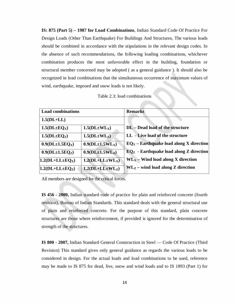
Table 2.3: load combinations
All members are designed for the critical forces.
IS 456 - 2000, Indian standard code of practice for plain and reinforced concrete (fourth
revision), Bureau of Indian Standards. This standard deals with the general structural use
of plain and reinforced concrete. For the purpose of this standard, plain concrete
structures are those where reinforcement, if provided is ignored for the determination of
strength of the structures.
IS 800 - 2007, Indian Standard General Construction in Steel — Code Of Practice (Third
Revision) This standard gives only general guidance as regards the various loads to be
considered in design. For the actual loads and load combinations to be used, reference
may be made to IS 875 for dead, live, snow and wind loads and to IS 1893 (Part 1) for
Load combinations Remarks
1.5(DL+LL)
DL – Dead load of the structure
LL - Live load of the structure
EQX – Earthquake load along X direction
EQZ - Earthquake load along Z direction
WLX – Wind load along X direction
WLZ – wind load along Z direction
1.5(DL±EQX) 1.5(DL±WLX)
1.5(DL±EQZ) 1.5(DL±WLZ)
0.9(DL±1.5EQX) 0.9(DL±1.5WLX)
0.9(DL±1.5EQZ) 0.9(DL±1.5WLZ)
1.2(DL+LL±EQX) 1.2(DL+LL±WLX)
1.2(DL+LL±EQZ) 1.2(DL+LL±WLZ)
15
earthquake loads. For seismic design, recommendations pertaining to steel frames only
are covered in this standard.
SP: 16 - 1980, Design Aids for Reinforced Concrete to IS: 456-1978 (third revision),
Bureau of Indian Standard. This is the explanatory handbook which covers the
basis/source of each clause. The objective of these design aids is to reduce design time in
the use of certain clauses in the Code for the design of beams, slabs and columns in
general building structures. The charts and tables included in the design aids were used in
calculation of footings and slabs.
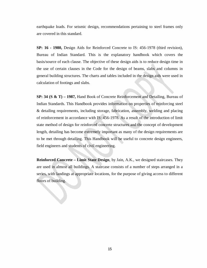
SP: 34 (S & T) – 1987, Hand Book of Concrete Reinforcement and Detailing, Bureau of
Indian Standards. This Handbook provides information on properties of reinforcing steel
& detailing requirements, including storage, fabrication, assembly, welding and placing
of reinforcement in accordance with IS: 456-1978. As a result of the introduction of limit
state method of design for reinforced concrete structures and the concept of development
length, detailing has become extremely important as many of the design requirements are
to be met through detailing. This Handbook will be useful to concrete design engineers,
field engineers and students of civil engineering.
Reinforced Concrete – Limit State Design, by Jain, A.K., we designed staircases. They
are used in almost all buildings. A staircase consists of a number of steps arranged in a
series, with landings at appropriate locations, for the purpose of giving access to different
floors of building.

16
CHAPTER - 3
WORKING WITH STAAD.Pro
17
CHAPTER - 3
WORKING WITH STAAD.Pro
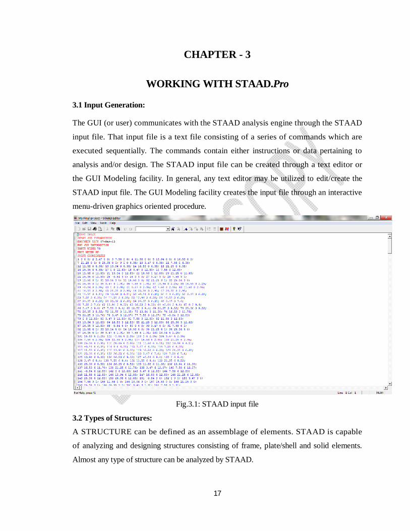
3.1 Input Generation:
The GUI (or user) communicates with the STAAD analysis engine through the STAAD
input file. That input file is a text file consisting of a series of commands which are
executed sequentially. The commands contain either instructions or data pertaining to
analysis and/or design. The STAAD input file can be created through a text editor or
the GUI Modeling facility. In general, any text editor may be utilized to edit/create the
STAAD input file. The GUI Modeling facility creates the input file through an interactive
menu-driven graphics oriented procedure.
Fig.3.1: STAAD input file
3.2 Types of Structures:
A STRUCTURE can be defined as an assemblage of elements. STAAD is capable
of analyzing and designing structures consisting of frame, plate/shell and solid elements.
Almost any type of structure can be analyzed by STAAD.
18
A SPACE structure, which is a three dimensional framed structure with loads applied in
any plane, is the most general.
A PLANE structure is bound by a global X-Y coordinate system with loads in the
same plane.
A TRUSS structure consists of truss members which can have only axial member forces
and no bending in the members.
A FLOOR structure is a two or three dimensional structure having no horizontal (global X
or Z) movement of the structure [FX, FZ & MY are restrained at every joint]. The floor
framing (in global X-Z plane) of a building is an ideal example of a FLOOR structure.
Columns can also be modeled with the floor in a FLOOR structure as long as the
structure has no horizontal loading. If there is any horizontal load, it must be analyzed as a
SPACE structure.
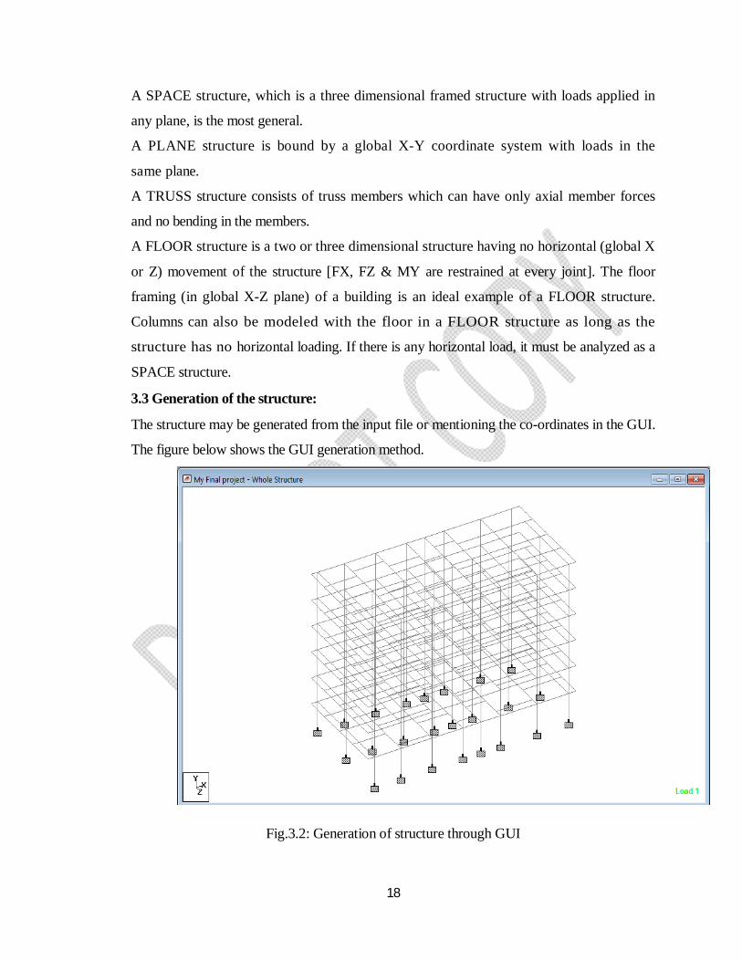
3.3 Generation of the structure:
The structure may be generated from the input file or mentioning the co-ordinates in the GUI.
The figure below shows the GUI generation method.
Fig.3.2: Generation of structure through GUI
19
3.4 Material Constants:
The material constants are: modulus of elasticity (E); weight density (DEN); Poisson's
ratio (POISS); co-efficient of thermal expansion (ALPHA), Composite Damping Ratio,
and beta angle (BETA) or coordinates for any reference (REF) point. E value for
members must be provided or the analysis will not be performed. Weight density (DEN)
is used only when self weight of the structure is to be taken into account. Poisson's ratio
(POISS) is used to calculate the shear modulus (commonly known as G) by the formula,
G = 0.5 x E/ (1 + POISS)
If Poisson's ratio is not provided, STAAD will assume a value for this quantity based on the
value of E. Coefficient of thermal expansion (ALPHA) is used to calculate the expansion of
the members if temperature loads are applied. The temperature unit for temperature load
and ALPHA has to be the same.
3.5 Supports:
Supports are specified as PINNED, FIXED or FIXED with different releases (known as
FIXED BUT). A pinned support has restraints against all translational movement and none
against rotational movement. In other words, a pinned support will have reactions for
all forces but will resist no moments. A fixed support has restraints against all
directions of movement. Translational and rotational springs can also be specified. The
springs are represented in terms of their spring constants. A translational spring constant is
defined as the force to displace a support joint one length unit in the specified global
direction. Similarly, a rotational spring constant is defined as the force to rotate the support
joint one degree around the specified global direction.
3.6 Loads:
Loads in a structure can be specified as joint load, member load, temperature load and fixed
end member load. STAAD can also generate the self-weight of the structure and use it
as uniformly distributed member loads in analysis. Any fraction of this self weight can
also be applied in any desired direction.
20
Joint loads:
Joint loads, both forces and moments, may be applied to any free joint of a structure.
These loads act in the global coordinate system of the structure. Positive forces act in the
positive coordinate directions. Any number of loads may be applied on a single joint, in
which case the loads will be additive on that joint.
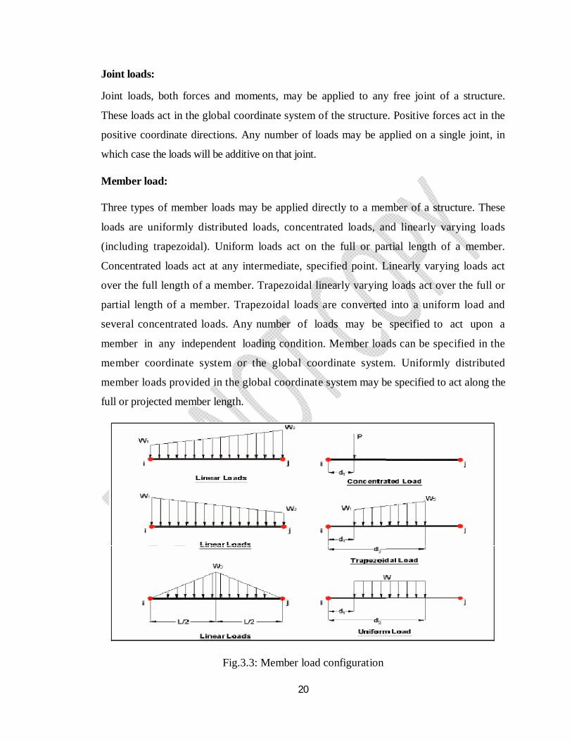
Member load:
Three types of member loads may be applied directly to a member of a structure. These
loads are uniformly distributed loads, concentrated loads, and linearly varying loads
(including trapezoidal). Uniform loads act on the full or partial length of a member.
Concentrated loads act at any intermediate, specified point. Linearly varying loads act
over the full length of a member. Trapezoidal linearly varying loads act over the full or
partial length of a member. Trapezoidal loads are converted into a uniform load and
several concentrated loads. Any number of loads may be specified to act upon a
member in any independent loading condition. Member loads can be specified in the
member coordinate system or the global coordinate system. Uniformly distributed
member loads provided in the global coordinate system may be specified to act along the
full or projected member length.
Fig.3.3: Member load configuration
21
Area/floor load:
Many times a floor (bound by X-Z plane) is subjected to a uniformly distributed
load. It could require a lot of work to calculate the member load for individual members in
that floor. However, with the AREA or FLOOR LOAD command, the user can specify
the area loads (unit load per unit square area) for members. The program will calculate the
tributary area for these members and provide the proper member loads. The Area Load
is used for one way distributions and the Floor Load is used for two way distributions.
Fixed end member load:
Load effects on a member may also be specified in terms of its fixed end loads. These
loads are given in terms of the member coordinate system and the directions are
opposite to the actual load on the member. Each end of a member can have six forces:
axial; shear y; shear z; torsion; moment y, and moment z.
Load Generator - Moving load, Wind & Seismic:
Load generation is the process of taking a load causing unit such as wind pressure,
ground movement or a truck on a bridge, and converting it to a form such as member load
or a joint load which can be then be used in the analysis.
Moving Load Generator:
This feature enables the user to generate moving loads on members of a structure.
Moving load system(s) consisting of concentrated loads at fixed specified distances in both
directions on a plane can be defined by the user. A user specified number of primary load
cases will be subsequently generated by the program and taken into consideration in analysis.
Seismic Load Generator:
The STAAD seismic load generator follows the procedure of equivalent lateral load
analysis. It is assumed that the lateral loads will be exerted in X and Z directions and Y
will be the direction of the gravity loads. Thus, for a building model, Y axis will be
perpendicular to the floors and point upward (all Y joint coordinates positive). For load
generation per the codes, the user is required to provide seismic zone coefficients,
importance factors, and soil characteristic parameters. Instead of using the approximate
22
code based formulas to estimate the building period in a certain direction, the program
calculates the period using Raleigh quotient technique. This period is then utilized to
calculate seismic coefficient C. After the base shear is calculated from the appropriate
equation, it is distributed among the various levels and roof per the specifications. The
distributed base shears are subsequently applied as lateral loads on the structure. These
loads may then be utilized as normal load cases for analysis and design.
Wind Load Generator:
The STAAD Wind Load generator is capable of calculating wind loads on joints
of a structure from user specified wind intensities and exposure factors. Different wind
intensities may be specified for different height zones of the structure. Openings in the
structure may be modeled using exposure factors. An exposure factor is associated
with each joint of the structure and is defined as the fraction of the influence area on
which the wind load acts. Built-in algorithms automatically calculate the exposed area
based on the areas bounded by members (plates and solids are not considered), then
calculates the wind loads from the intensity and exposure input and distributes the loads
as lateral joint loads.
3.7 Section Types for Concrete Design:
The following types of cross sections for concrete members can be designed.
For Beams Prismatic (Rectangular & Square) &
T-shape For Columns Prismatic (Rectangular, Square and Circular)
3.8 Design Parameters:
The program contains a number of parameters that are needed to perform design as per
IS: 13920. It accepts all parameters that are needed to perform design as per IS: 456.
Over and above it has some other parameters that are required only when designed is
performed as per IS: 13920. Default parameter values have been selected such that they
are frequently used numbers for conventional design requirements. These values may
23
be changed to suit the particular design being performed by this manual contains a
complete list of the available parameters and their default values. It is necessary to
declare length and force units as Millimeter and Newton before performing the concrete
design.
3.9 Beam Design:
Beams are designed for flexure, shear and torsion. If required the effect of the axial force
may be taken into consideration. For all these forces, all active beam loadings are pre-
scanned to identify the critical load cases at different sections of the beams. For design to
be performed as per IS: 13920 the width of the member shall not be less than 200mm.
Also the member shall preferably have a width-to depth ratio of more than 0.3.
Design for Flexure:
Design procedure is same as that for IS: 456. However while designing following criteria
are satisfied as per IS: 13920
1. The minimum grade of concrete shall preferably be M25.
2. Steel reinforcements of grade Fe415 or less only shall be used.
3. The minimum tension steel ratio on any face, at any section, is given by:
ρmin = 0.24√fck/fy
The maximum steel ratio on any face, at any section, is given by ρmax = 0.025.
4. The positive steel ratio at a joint face must be at least equal to half the negative steel
at that face.
5. The steel provided at each of the top and bottom face, at any section, shall at least be
equal to one-fourth of the maximum negative moment steel provided at the face
of either joint.
24
Design for Shear:
The Shear force to be resisted by vertical hoops is guided by the IS 13920:1993
revision. Elastic sagging and hogging moments of resistance of the beam section
at ends are considered while calculating shear force. Plastic sagging and hogging
moments of resistance can also be considered for shear design if PLASTIC parameter is
mentioned in the input file. Shear reinforcement is calculated to resist both shear forces and
torsional moments.
3.10 Column Design:
Columns are designed for axial forces and biaxial moments per IS 456:2000. Columns
are also designed for shear forces. All major criteria for selecting longitudinal and
transverse reinforcement as stipulated by IS: 456 have been taken care of in the
column design of STAAD. However following clauses have been satisfied to
incorporate provisions of IS: 13920
1. The minimum grade of concrete shall preferably be M25.
2. Steel reinforcements of grade Fe415 or less only shall be used.
3. The minimum dimension of column member shall not be less than 200 mm. For
columns having unsupported length exceeding 4m, the shortest dimension of
column shall not be less than 300 mm.
4. The ratio of the shortest cross-sectional dimension to the perpendicular dimension
shall preferably be not less than 0.
5. The spacing of hoops shall not exceed half the least lateral dimension of the
column, except where special confining reinforcement is provided.
6. Special confining reinforcement shall be provided over a length lo from each
joint face, towards mid span, and on either side of any section, where flexural
yielding may occur. The length lo shall not be less than a) larger lateral dimension
of the member at the section where yielding occurs, b) 1/6 of clear span of the
member, and c) 450 mm.
7. The spacing of hoops used as special confining reinforcement shall not exceed
¼ of minimum member dimension but need not be less than 75 mm nor > 100 mm.
25
3.11 Design Operations:
STAAD contains a broad set of facilities for designing structural members as
individual components of an analyzed structure. The member design facilities provide the
user with the ability to carry out a number of different design operations. These
facilities may design problem. The operations to perform a design are:
Specify the members and the load cases to be considered in the design.
Specify whether to perform code checking or member selection.
Specify design parameter values, if different from the default values.
Specify whether to perform member selection by optimization.
These operations may be repeated by the user any number of times depending upon
the design requirements. Earthquake motion often induces force large enough to cause
inelastic deformations in the structure. If the structure is brittle, sudden failure could occur.
But if the structure is made to behave ductile, it will be able to sustain the earthquake
effects better with some deflection larger than the yield deflection by absorption of energy.
Therefore ductility is also required as an essential element for safety from sudden collapse
during severe shocks. STAAD has the capabilities of performing concrete design as per
IS: 13920. While designing it satisfies all provisions of IS: 456 - 2000 and IS: 13920 for
beams and columns.
3.12 General Comments:
This section presents some general statements regarding the implementation of Indian
Standard code of practice (IS: 800 - 1984) for structural steel design in STAAD. The
design philosophy and procedural logistics for member selection and code checking are
based upon the principles of allowable stress design. Two major failure modes are
recognized: failure by overstressing, and failure by stability considerations. The
flowing sections describe the salient features of the allowable stresses being calculated
and the stability criteria being used. Members are proportioned to resist the design loads
without exceeding the allowable stresses and the most economic section is selected on
the basis of least weight criteria. The code checking part of the program checks
26
stability and strength requirements and reports the critical loading condition and the
governing code criteria. It is generally assumed that the user will take care of the detailing
requirements like provision of stiffeners and check the local effects such as flange
buckling and web crippling.
Allowable Stresses:
The member design and code checking in STAAD are based upon the allowable stress design
method as per IS: 800 (1984). It is a method for proportioning structural members
using design loads and forces, allowable stresses, and design limitations for the appropriate
material under service conditions. It would not be possible to describe every aspect of
IS: 800 in this manual. This section, however, will discuss the salient features of the
allowable stresses specified by IS: 800 and implemented in STAAD. Appropriate
sections of IS: 800 will be referenced during the discussion of various types of allowable
stresses.
Multiple Analyses:
Structural analysis/design may require multiple analyses in the same run. STAAD allows
the user to change input such as member properties, support conditions etc. in an input
file to facilitate multiple analyses in the same run. Results from different analyses may be
combined for design purposes. For structures with bracing, it may be necessary to
make certain members inactive for a particular load case and subsequently activate
them for another. STAAD provides an INACTIVE facility for this type of analysis.
3.13 Post Processing Facilities:
All output from the STAAD run may be utilized for further processing by the
STAAD.Pro GUI.
Stability Requirements:
Slenderness ratios are calculated for all members and checked against the
appropriate maximum values. IS: 800 summarize the maximum slenderness ratios for
27
different types of members. In STAAD implementation of IS: 800, appropriate maximum
slenderness ratio can be provided for each member. If no maximum slenderness ratio is
provided, compression members will be checked against a maximum value of 180 and
tension members will be checked against a maximum value of 400.
Deflection Check:
This facility allows the user to consider deflection as criteria in the CODE CHECK
and MEMBER SELECTION processes. The deflection check may be controlled
using three parameters. Deflection is used in addition to other strength and stability
related criteria. The local deflection calculation is based on the latest analysis results.
Earthquake Collapse Check:
This checks at each column / beam interface, the program checks that the capacity of the
column exceeds the total capacity of all beams that connect to it. The earthquake check
only uses the results from Design Groups that have Design Briefs from the selected
Design Code.
Code Checking:
The purpose of code checking is to verify whether the specified section is capable
of satisfying applicable design code requirements. The code checking is based on the
IS: 800 (1984) requirements. Forces and moments at specified sections of the members
are utilized for the code checking calculations. Sections may be specified using the
BEAM parameter or the SECTION command. If no sections are specified, the code
checking is based on forces and moments at the member ends.
28
CHAPTER - 4
ANALYSIS OF STILT + G + 4 RCC FRAMED BUILDING
USING STAAD.Pro
29
CHAPTER - 4
ANALYSIS OF STILT + G + 4 RCC FRAMED BUILDING
USING STAAD.Pro
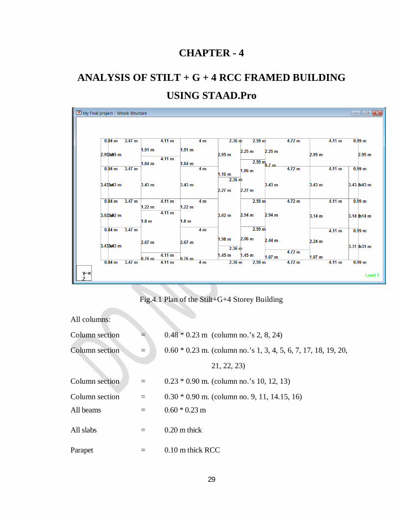
Fig.4.1 Plan of the Stilt+G+4 Storey Building
All columns:
Column section = 0.48 * 0.23 m (column no.’s 2, 8, 24)
Column section = 0.60 * 0.23 m. (column no.’s 1, 3, 4, 5, 6, 7, 17, 18, 19, 20,
21, 22, 23)
Column section = 0.23 * 0.90 m. (column no.’s 10, 12, 13)
Column section = 0.30 * 0.90 m. (column no. 9, 11, 14.15, 16)
All beams = 0.60 * 0.23 m
All slabs = 0.20 m thick
Parapet = 0.10 m thick RCC
30
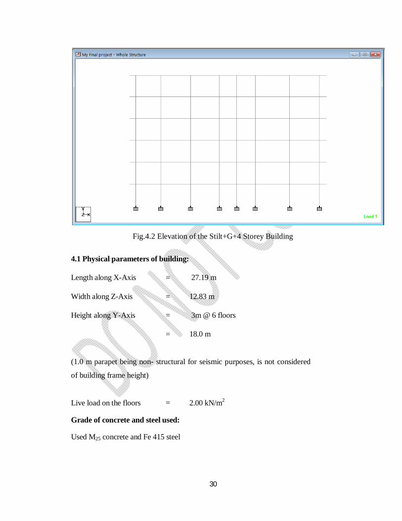
Fig.4.2 Elevation of the Stilt+G+4 Storey Building
4.1 Physical parameters of building:
Length along X-Axis = 27.19 m
Width along Z-Axis = 12.83 m
Height along Y-Axis = 3m @ 6 floors
= 18.0 m
(1.0 m parapet being non- structural for seismic purposes, is not considered
of building frame height)
Live load on the floors = 2.00 kN/m2
Grade of concrete and steel used:
Used M25 concrete and Fe 415 steel
31
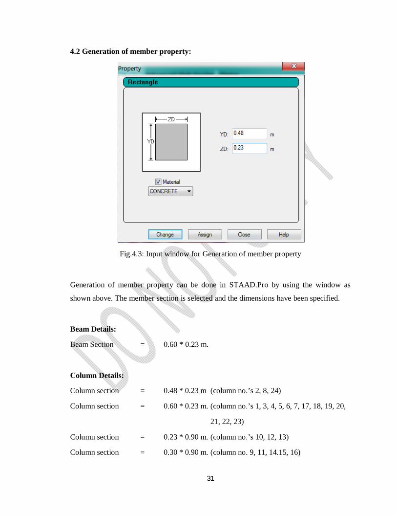
4.2 Generation of member property:
Fig.4.3: Input window for Generation of member property
Generation of member property can be done in STAAD.Pro by using the window as
shown above. The member section is selected and the dimensions have been specified.
Beam Details:
Beam Section = 0.60 * 0.23 m.
Column Details:
Column section = 0.48 * 0.23 m (column no.’s 2, 8, 24)
Column section = 0.60 * 0.23 m. (column no.’s 1, 3, 4, 5, 6, 7, 17, 18, 19, 20,
21, 22, 23)
Column section = 0.23 * 0.90 m. (column no.’s 10, 12, 13)
Column section = 0.30 * 0.90 m. (column no. 9, 11, 14.15, 16)
32
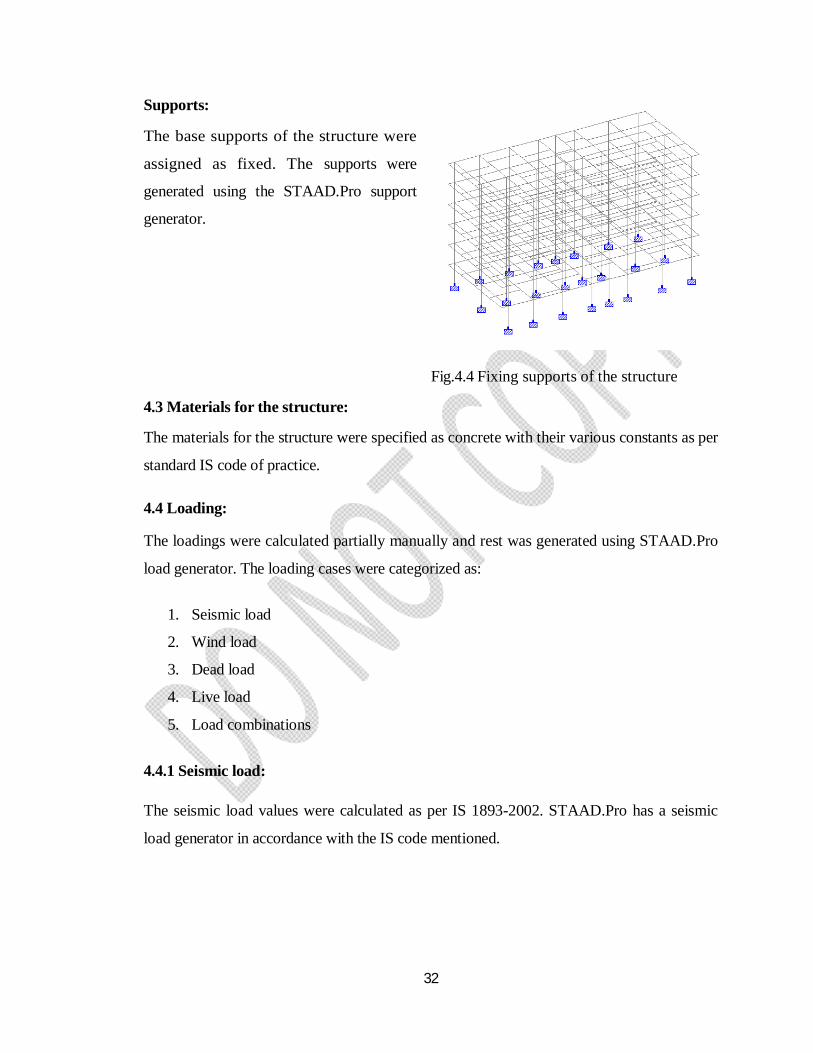
Supports:
The base supports of the structure were
assigned as fixed. The supports were
generated using the STAAD.Pro support
generator.
Fig.4.4 Fixing supports of the structure
4.3 Materials for the structure:
The materials for the structure were specified as concrete with their various constants as per
standard IS code of practice.
4.4 Loading:
The loadings were calculated partially manually and rest was generated using STAAD.Pro
load generator. The loading cases were categorized as:
1. Seismic load
2. Wind load
3. Dead load
4. Live load
5. Load combinations
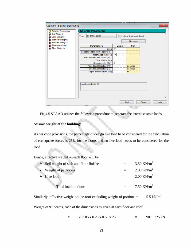
4.4.1 Seismic load:
The seismic load values were calculated as per IS 1893-2002. STAAD.Pro has a seismic
load generator in accordance with the IS code mentioned.
33
Fig.4.5 STAAD utilizes the following procedure to generate the lateral seismic loads.
Seismic weight of the building:
As per code provisions, the percentage of design live load to be considered for the calculation
of earthquake forces is 25% for the floors and no live load needs to be considered for the
roof.
Hence, effective weight on each floor will be
Self weight of slab and floor finishes = 3.50 KN/m2
Weight of partitions = 2.00 KN/m2
Live load = 2.00 KN/m2
Total load on floor = 7.50 KN/m2
Similarly, effective weight on the roof excluding weight of portions = 5.5 kN/m2
Weight of 97 beams, each of the dimensions as given at each floor and roof
= 263.05 x 0.23 x 0.60 x 25 = 907.5225 kN
34
Weight of 24 columns at each floor = 4.0952 x (3.0 – 0.60) x 25
= 245.712 kN
Weight of 24 columns at roof = ½ x 245.712
= 122.86 kN
Plan area of the building is 27.09 m x 12.63 m = 348.85 m2
Equivalent load at roof at roof level = (5.5 x 348.85) + 907.5225 + 122.86
= 2949.05 kN
Equivalent load at roof at floor level = (7.5 x 348.85) + 907.5225 + 245.712
= 3769.60 kN
Seismic weight of the building, W = 2949.05 + (3769.60 x 5)
= 21797.05 kN
Base shear:
The fundamental natural period of vibration (T) for the buildings having shear walls is given
by 푻 = ퟎ.ퟎퟗ 푯√푫
= . √ .
= 0.45 (d, the plan dimension = 12.83 m)
Building is situated at Visakhapatnam which comes under Zone –II with Zone factor of 0.10
m and give the importance factor (I) as 1.5, Response reduction factor, R = 5.0
For 5% of damping and type I soil, average response acceleration coefficient Sa/g
(From IS: 1893 – 2000)
Sa/g = 1.0/T, 0.40 ≤ T ≤ 4.0
Sa/g = 1.0/0.45 = 2.22
35
Design horizontal seismic coefficient, Ah = 풁푰푺풂ퟐ푹품
= . . .
= 0.033
Base shear VB = Ah x W = 0.033 x 21797.05
= 719.30 kN
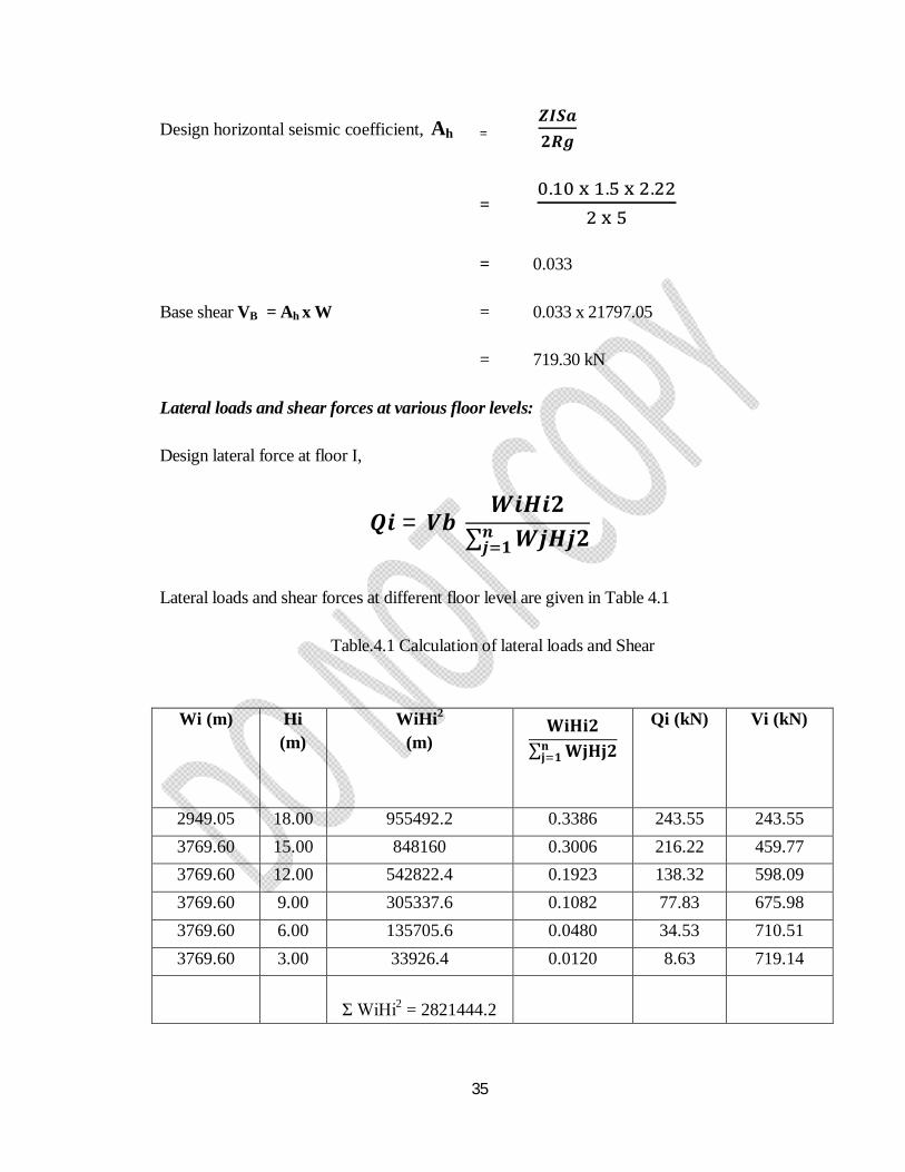
Lateral loads and shear forces at various floor levels:
Design lateral force at floor I,
푸풊 = 푽풃 푾풊푯풊ퟐ
∑ 푾풋푯풋ퟐ풏풋 ퟏ
Lateral loads and shear forces at different floor level are given in Table 4.1
Table.4.1 Calculation of lateral loads and Shear
Wi (m) Hi (m)
WiHi2
(m) 퐖퐢퐇퐢ퟐ
∑ 퐖퐣퐇퐣ퟐ퐧퐣 ퟏ
Qi (kN) Vi (kN)
2949.05 18.00 955492.2 0.3386 243.55 243.55 3769.60 15.00 848160 0.3006 216.22 459.77 3769.60 12.00 542822.4 0.1923 138.32 598.09 3769.60 9.00 305337.6 0.1082 77.83 675.98 3769.60 6.00 135705.6 0.0480 34.53 710.51 3769.60 3.00 33926.4 0.0120 8.63 719.14
Ʃ WiHi2 = 2821444.2
36
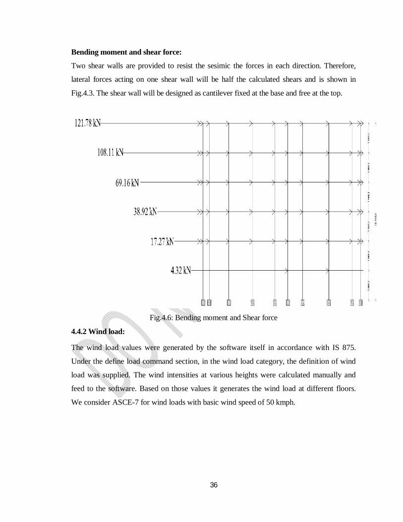
Bending moment and shear force:
Two shear walls are provided to resist the sesimic the forces in each direction. Therefore,
lateral forces acting on one shear wall will be half the calculated shears and is shown in
Fig.4.3. The shear wall will be designed as cantilever fixed at the base and free at the top.
Fig.4.6: Bending moment and Shear force
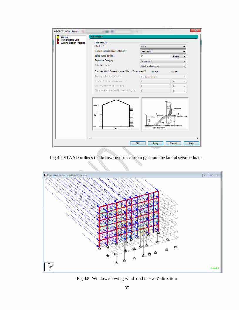
4.4.2 Wind load:
The wind load values were generated by the software itself in accordance with IS 875.
Under the define load command section, in the wind load category, the definition of wind
load was supplied. The wind intensities at various heights were calculated manually and
feed to the software. Based on those values it generates the wind load at different floors.
We consider ASCE-7 for wind loads with basic wind speed of 50 kmph.
37
Fig.4.7 STAAD utilizes the following procedure to generate the lateral seismic loads.
Fig.4.8: Window showing wind load in +ve Z-direction
38
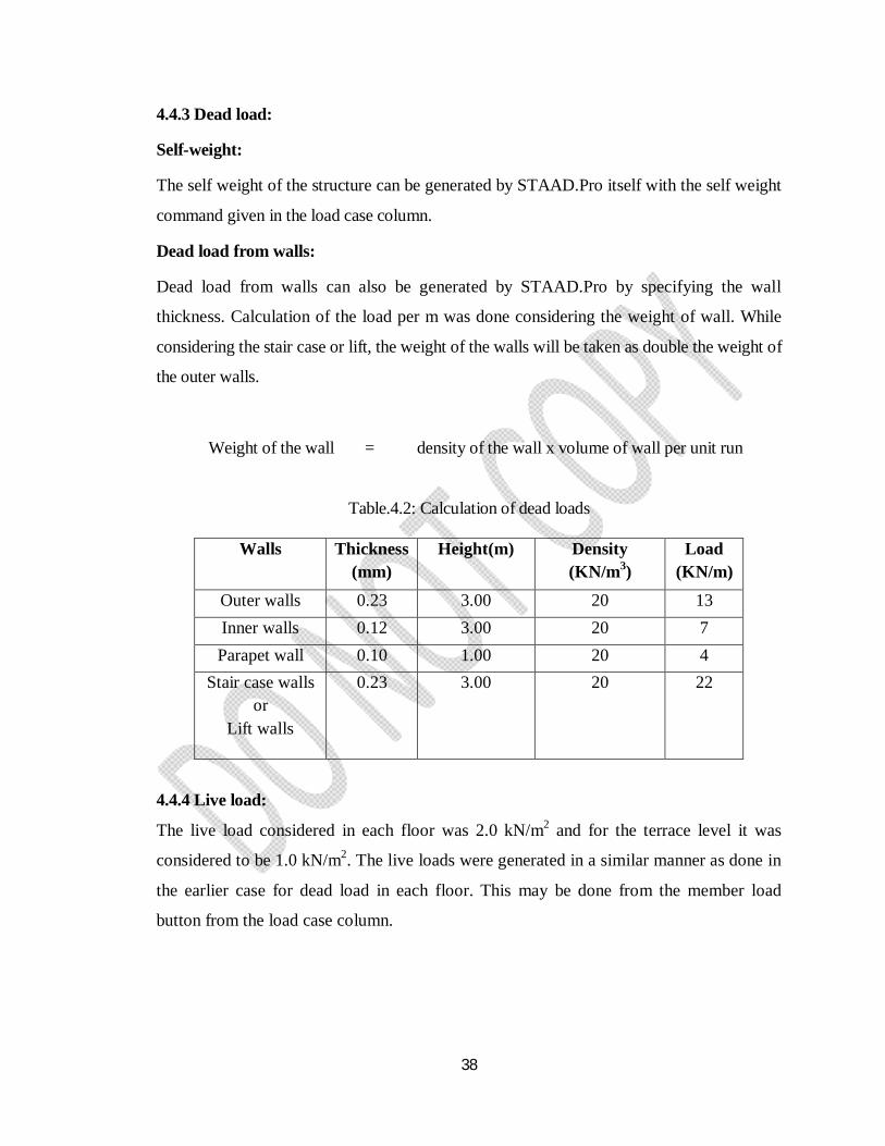
4.4.3 Dead load:
Self-weight:
The self weight of the structure can be generated by STAAD.Pro itself with the self weight
command given in the load case column.
Dead load from walls:
Dead load from walls can also be generated by STAAD.Pro by specifying the wall
thickness. Calculation of the load per m was done considering the weight of wall. While
considering the stair case or lift, the weight of the walls will be taken as double the weight of
the outer walls.
Weight of the wall = density of the wall x volume of wall per unit run
Table.4.2: Calculation of dead loads
4.4.4 Live load:
The live load considered in each floor was 2.0 kN/m2 and for the terrace level it was
considered to be 1.0 kN/m2. The live loads were generated in a similar manner as done in
the earlier case for dead load in each floor. This may be done from the member load
button from the load case column.
Walls Thickness(mm)
Height(m) Density (KN/m3)
Load (KN/m)
Outer walls 0.23 3.00 20 13 Inner walls 0.12 3.00 20 7 Parapet wall 0.10 1.00 20 4
Stair case walls or
Lift walls
0.23 3.00 20 22
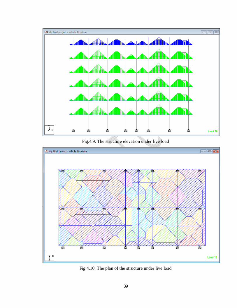
39
Fig.4.9: The structure elevation under live load
Fig.4.10: The plan of the structure under live load
40
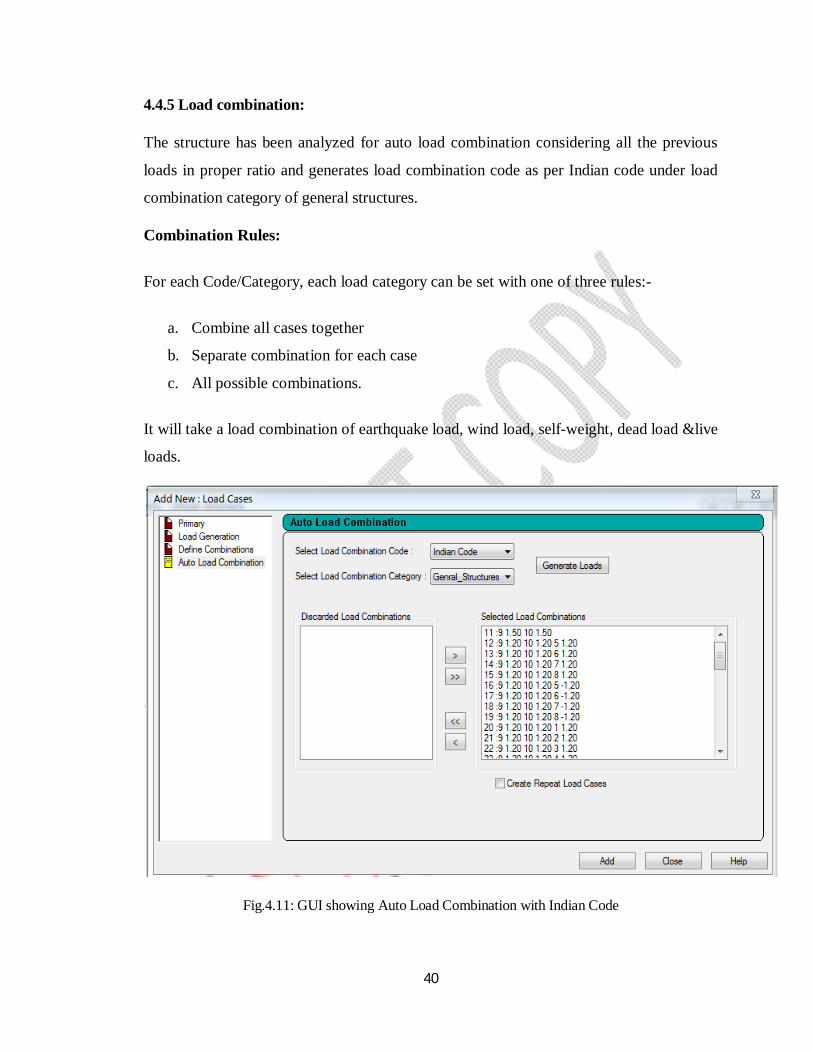
4.4.5 Load combination:
The structure has been analyzed for auto load combination considering all the previous
loads in proper ratio and generates load combination code as per Indian code under load
combination category of general structures.
Combination Rules:
For each Code/Category, each load category can be set with one of three rules:-
a. Combine all cases together
b. Separate combination for each case
c. All possible combinations.
It will take a load combination of earthquake load, wind load, self-weight, dead load &live
loads.
Fig.4.11: GUI showing Auto Load Combination with Indian Code
41
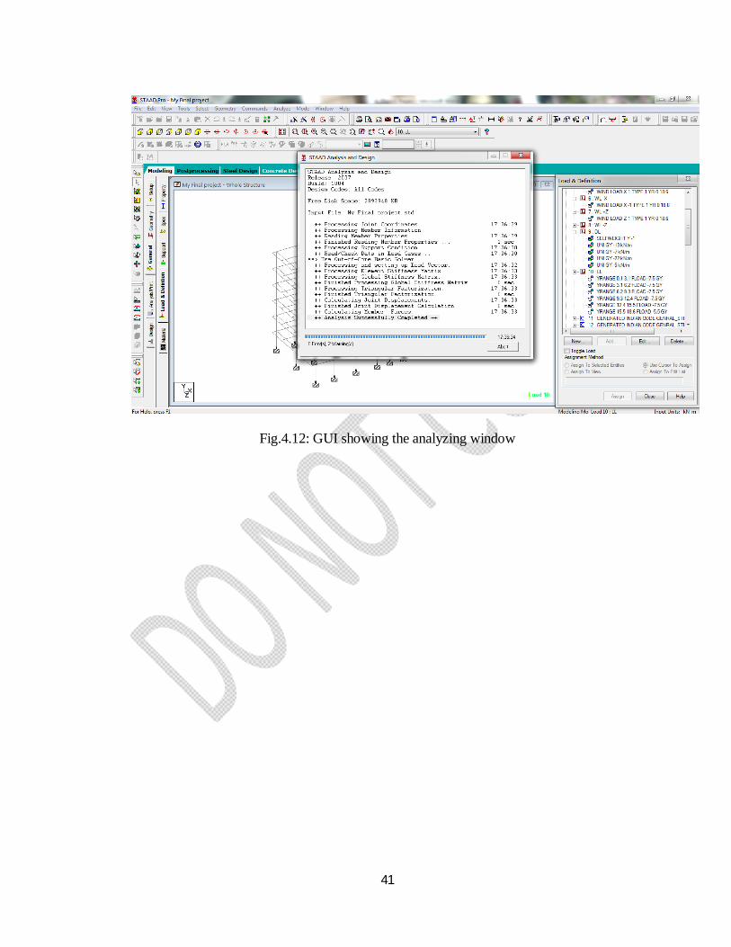
Fig.4.12: GUI showing the analyzing window
42
CHAPTER - 5
DESIGN OF [STILT + G + 4] RCC FRAMED
BUILDING USING STAAD.Pro
43
CHAPTER - 5
DESIGN OF [STILT + G + 4] RCC FRAMED BUILDING
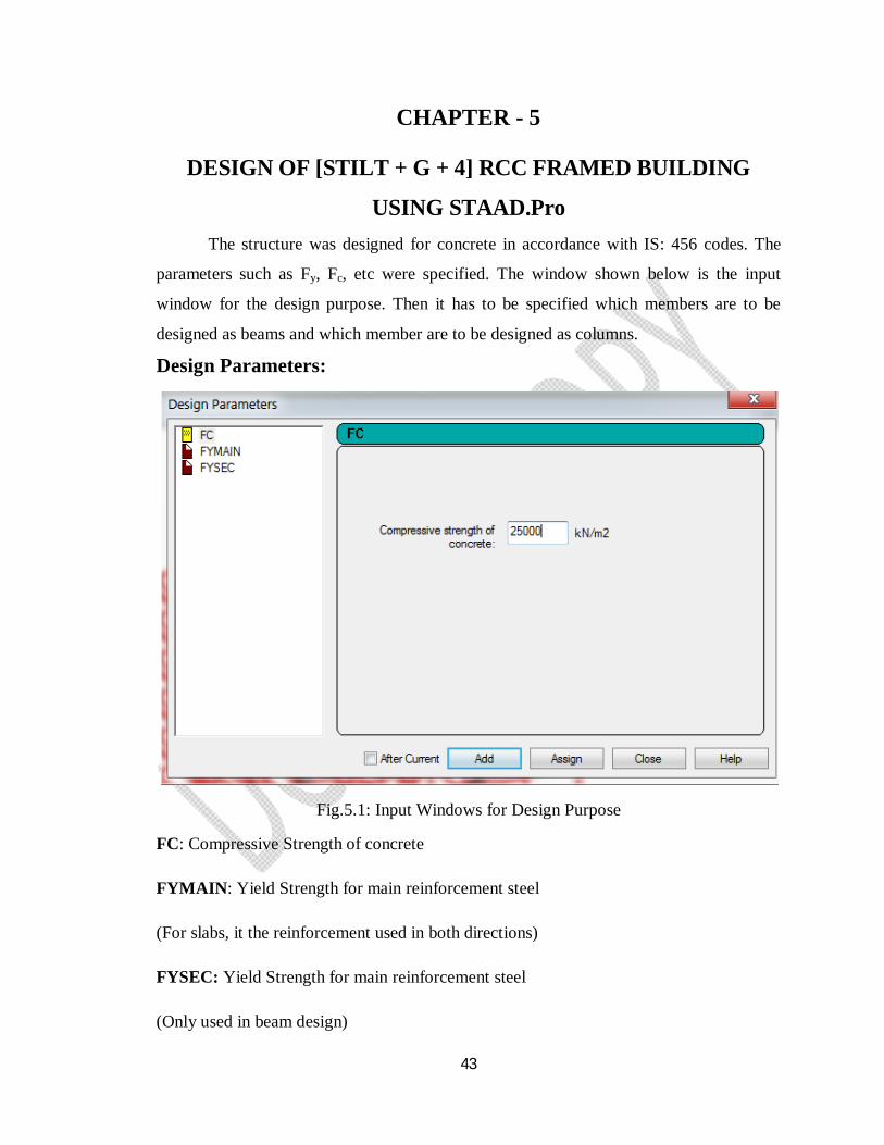
USING STAAD.Pro The structure was designed for concrete in accordance with IS: 456 codes. The
parameters such as Fy, Fc, etc were specified. The window shown below is the input
window for the design purpose. Then it has to be specified which members are to be
designed as beams and which member are to be designed as columns.
Design Parameters:
Fig.5.1: Input Windows for Design Purpose
FC: Compressive Strength of concrete
FYMAIN: Yield Strength for main reinforcement steel
(For slabs, it the reinforcement used in both directions)
FYSEC: Yield Strength for main reinforcement steel
(Only used in beam design)
44
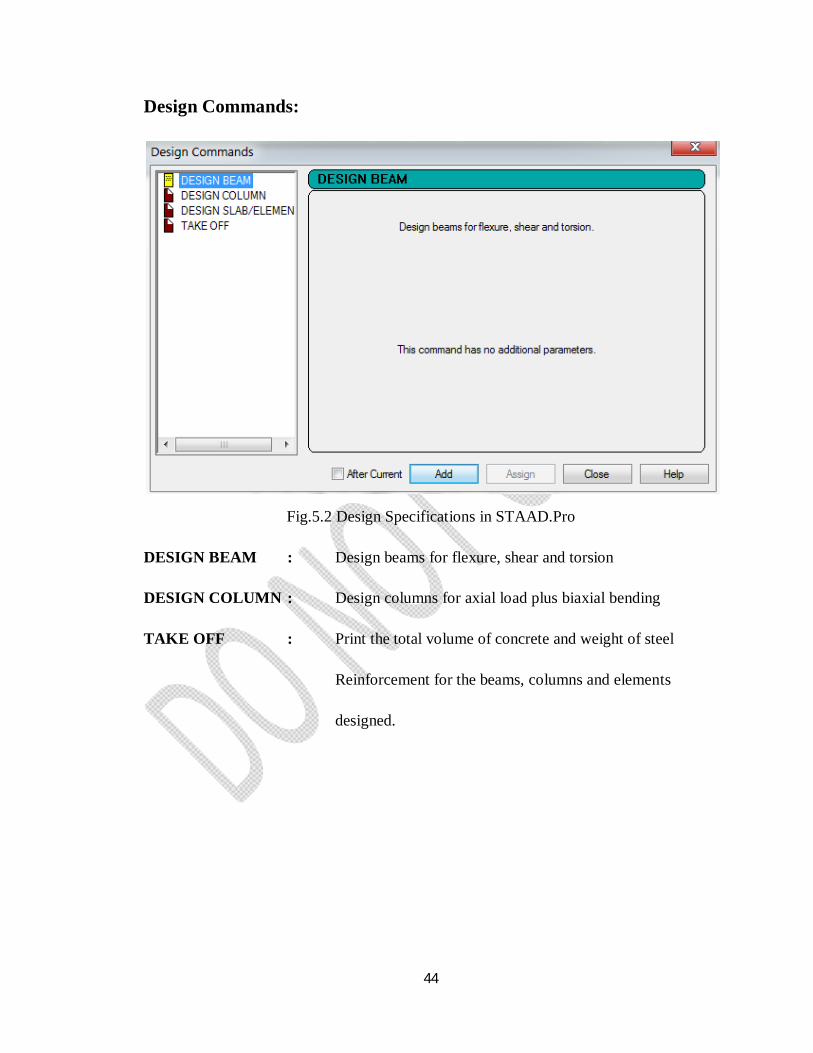
Design Commands:
Fig.5.2 Design Specifications in STAAD.Pro
DESIGN BEAM : Design beams for flexure, shear and torsion
DESIGN COLUMN : Design columns for axial load plus biaxial bending
TAKE OFF : Print the total volume of concrete and weight of steel
Reinforcement for the beams, columns and elements
designed.

45
CHAPTER - 6
STAAD.Pro INPUT COMMAND FILE
46
CHAPTER - 6
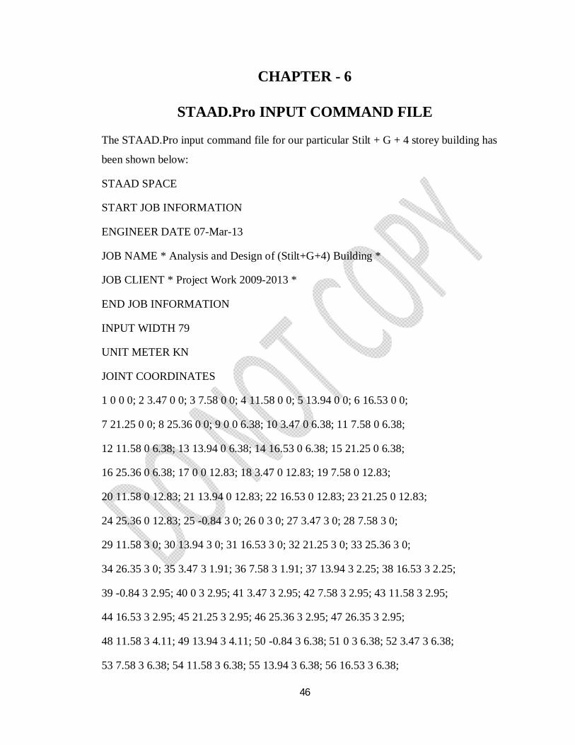
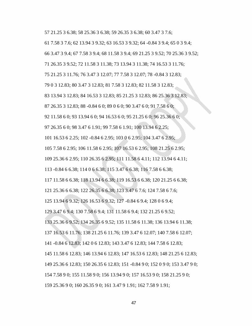
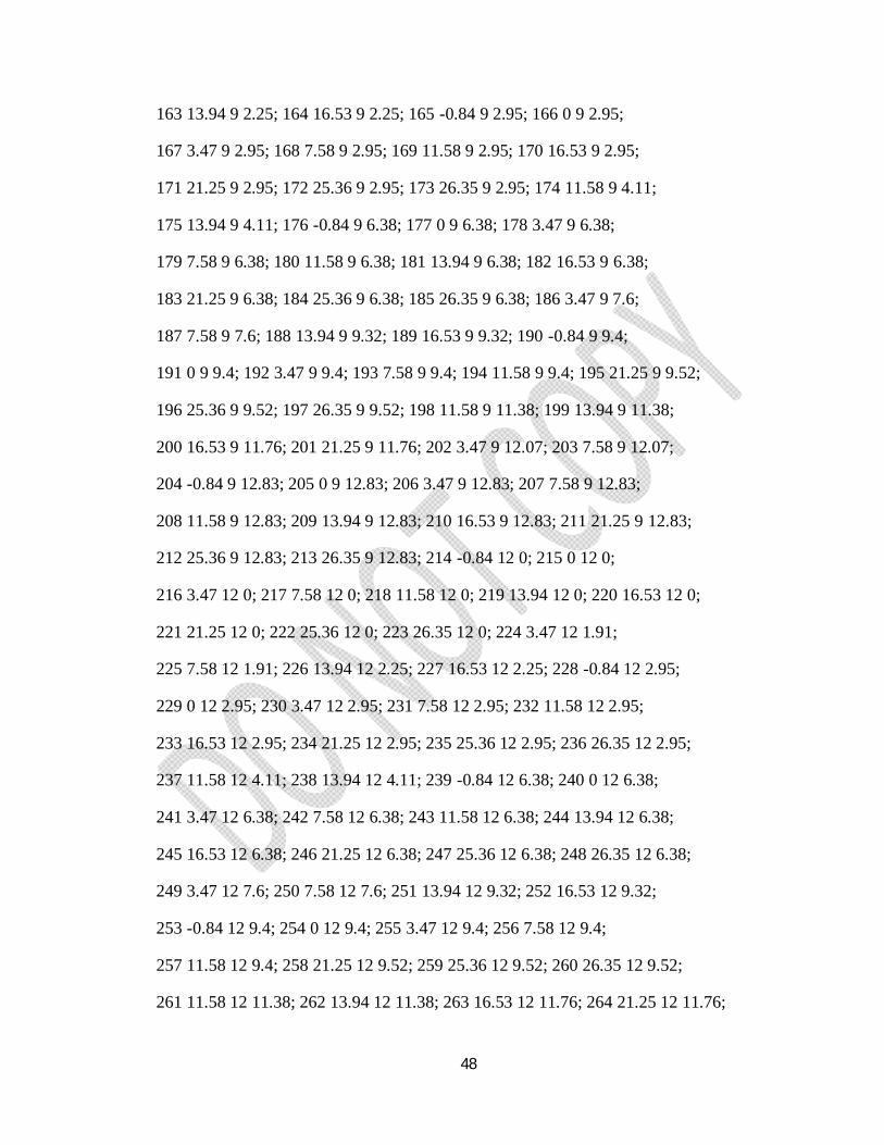
STAAD.Pro INPUT COMMAND FILE
The STAAD.Pro input command file for our particular Stilt + G + 4 storey building has
been shown below:
STAAD SPACE
START JOB INFORMATION
ENGINEER DATE 07-Mar-13
JOB NAME * Analysis and Design of (Stilt+G+4) Building *
JOB CLIENT * Project Work 2009-2013 *
END JOB INFORMATION
INPUT WIDTH 79
UNIT METER KN
JOINT COORDINATES
1 0 0 0; 2 3.47 0 0; 3 7.58 0 0; 4 11.58 0 0; 5 13.94 0 0; 6 16.53 0 0;
7 21.25 0 0; 8 25.36 0 0; 9 0 0 6.38; 10 3.47 0 6.38; 11 7.58 0 6.38;
12 11.58 0 6.38; 13 13.94 0 6.38; 14 16.53 0 6.38; 15 21.25 0 6.38;
16 25.36 0 6.38; 17 0 0 12.83; 18 3.47 0 12.83; 19 7.58 0 12.83;
20 11.58 0 12.83; 21 13.94 0 12.83; 22 16.53 0 12.83; 23 21.25 0 12.83;
24 25.36 0 12.83; 25 -0.84 3 0; 26 0 3 0; 27 3.47 3 0; 28 7.58 3 0;
29 11.58 3 0; 30 13.94 3 0; 31 16.53 3 0; 32 21.25 3 0; 33 25.36 3 0;
34 26.35 3 0; 35 3.47 3 1.91; 36 7.58 3 1.91; 37 13.94 3 2.25; 38 16.53 3 2.25;
39 -0.84 3 2.95; 40 0 3 2.95; 41 3.47 3 2.95; 42 7.58 3 2.95; 43 11.58 3 2.95;
44 16.53 3 2.95; 45 21.25 3 2.95; 46 25.36 3 2.95; 47 26.35 3 2.95;
48 11.58 3 4.11; 49 13.94 3 4.11; 50 -0.84 3 6.38; 51 0 3 6.38; 52 3.47 3 6.38;
53 7.58 3 6.38; 54 11.58 3 6.38; 55 13.94 3 6.38; 56 16.53 3 6.38;
47
57 21.25 3 6.38; 58 25.36 3 6.38; 59 26.35 3 6.38; 60 3.47 3 7.6;
61 7.58 3 7.6; 62 13.94 3 9.32; 63 16.53 3 9.32; 64 -0.84 3 9.4; 65 0 3 9.4;
66 3.47 3 9.4; 67 7.58 3 9.4; 68 11.58 3 9.4; 69 21.25 3 9.52; 70 25.36 3 9.52;
71 26.35 3 9.52; 72 11.58 3 11.38; 73 13.94 3 11.38; 74 16.53 3 11.76;
75 21.25 3 11.76; 76 3.47 3 12.07; 77 7.58 3 12.07; 78 -0.84 3 12.83;
79 0 3 12.83; 80 3.47 3 12.83; 81 7.58 3 12.83; 82 11.58 3 12.83;
83 13.94 3 12.83; 84 16.53 3 12.83; 85 21.25 3 12.83; 86 25.36 3 12.83;
87 26.35 3 12.83; 88 -0.84 6 0; 89 0 6 0; 90 3.47 6 0; 91 7.58 6 0;
92 11.58 6 0; 93 13.94 6 0; 94 16.53 6 0; 95 21.25 6 0; 96 25.36 6 0;
97 26.35 6 0; 98 3.47 6 1.91; 99 7.58 6 1.91; 100 13.94 6 2.25;
101 16.53 6 2.25; 102 -0.84 6 2.95; 103 0 6 2.95; 104 3.47 6 2.95;
105 7.58 6 2.95; 106 11.58 6 2.95; 107 16.53 6 2.95; 108 21.25 6 2.95;
109 25.36 6 2.95; 110 26.35 6 2.95; 111 11.58 6 4.11; 112 13.94 6 4.11;
113 -0.84 6 6.38; 114 0 6 6.38; 115 3.47 6 6.38; 116 7.58 6 6.38;
117 11.58 6 6.38; 118 13.94 6 6.38; 119 16.53 6 6.38; 120 21.25 6 6.38;
121 25.36 6 6.38; 122 26.35 6 6.38; 123 3.47 6 7.6; 124 7.58 6 7.6;
125 13.94 6 9.32; 126 16.53 6 9.32; 127 -0.84 6 9.4; 128 0 6 9.4;
129 3.47 6 9.4; 130 7.58 6 9.4; 131 11.58 6 9.4; 132 21.25 6 9.52;
133 25.36 6 9.52; 134 26.35 6 9.52; 135 11.58 6 11.38; 136 13.94 6 11.38;
137 16.53 6 11.76; 138 21.25 6 11.76; 139 3.47 6 12.07; 140 7.58 6 12.07;
141 -0.84 6 12.83; 142 0 6 12.83; 143 3.47 6 12.83; 144 7.58 6 12.83;
145 11.58 6 12.83; 146 13.94 6 12.83; 147 16.53 6 12.83; 148 21.25 6 12.83;
149 25.36 6 12.83; 150 26.35 6 12.83; 151 -0.84 9 0; 152 0 9 0; 153 3.47 9 0;
154 7.58 9 0; 155 11.58 9 0; 156 13.94 9 0; 157 16.53 9 0; 158 21.25 9 0;
159 25.36 9 0; 160 26.35 9 0; 161 3.47 9 1.91; 162 7.58 9 1.91;
48
163 13.94 9 2.25; 164 16.53 9 2.25; 165 -0.84 9 2.95; 166 0 9 2.95;
167 3.47 9 2.95; 168 7.58 9 2.95; 169 11.58 9 2.95; 170 16.53 9 2.95;
171 21.25 9 2.95; 172 25.36 9 2.95; 173 26.35 9 2.95; 174 11.58 9 4.11;
175 13.94 9 4.11; 176 -0.84 9 6.38; 177 0 9 6.38; 178 3.47 9 6.38;
179 7.58 9 6.38; 180 11.58 9 6.38; 181 13.94 9 6.38; 182 16.53 9 6.38;
183 21.25 9 6.38; 184 25.36 9 6.38; 185 26.35 9 6.38; 186 3.47 9 7.6;
187 7.58 9 7.6; 188 13.94 9 9.32; 189 16.53 9 9.32; 190 -0.84 9 9.4;
191 0 9 9.4; 192 3.47 9 9.4; 193 7.58 9 9.4; 194 11.58 9 9.4; 195 21.25 9 9.52;
196 25.36 9 9.52; 197 26.35 9 9.52; 198 11.58 9 11.38; 199 13.94 9 11.38;
200 16.53 9 11.76; 201 21.25 9 11.76; 202 3.47 9 12.07; 203 7.58 9 12.07;
204 -0.84 9 12.83; 205 0 9 12.83; 206 3.47 9 12.83; 207 7.58 9 12.83;
208 11.58 9 12.83; 209 13.94 9 12.83; 210 16.53 9 12.83; 211 21.25 9 12.83;
212 25.36 9 12.83; 213 26.35 9 12.83; 214 -0.84 12 0; 215 0 12 0;
216 3.47 12 0; 217 7.58 12 0; 218 11.58 12 0; 219 13.94 12 0; 220 16.53 12 0;
221 21.25 12 0; 222 25.36 12 0; 223 26.35 12 0; 224 3.47 12 1.91;
225 7.58 12 1.91; 226 13.94 12 2.25; 227 16.53 12 2.25; 228 -0.84 12 2.95;
229 0 12 2.95; 230 3.47 12 2.95; 231 7.58 12 2.95; 232 11.58 12 2.95;
233 16.53 12 2.95; 234 21.25 12 2.95; 235 25.36 12 2.95; 236 26.35 12 2.95;
237 11.58 12 4.11; 238 13.94 12 4.11; 239 -0.84 12 6.38; 240 0 12 6.38;
241 3.47 12 6.38; 242 7.58 12 6.38; 243 11.58 12 6.38; 244 13.94 12 6.38;
245 16.53 12 6.38; 246 21.25 12 6.38; 247 25.36 12 6.38; 248 26.35 12 6.38;
249 3.47 12 7.6; 250 7.58 12 7.6; 251 13.94 12 9.32; 252 16.53 12 9.32;
253 -0.84 12 9.4; 254 0 12 9.4; 255 3.47 12 9.4; 256 7.58 12 9.4;
257 11.58 12 9.4; 258 21.25 12 9.52; 259 25.36 12 9.52; 260 26.35 12 9.52;
261 11.58 12 11.38; 262 13.94 12 11.38; 263 16.53 12 11.76; 264 21.25 12 11.76;
49
265 3.47 12 12.07; 266 7.58 12 12.07; 267 -0.84 12 12.83; 268 0 12 12.83;
269 3.47 12 12.83; 270 7.58 12 12.83; 271 11.58 12 12.83; 272 13.94 12 12.83;
273 16.53 12 12.83; 274 21.25 12 12.83; 275 25.36 12 12.83; 276 26.35 12 12.83;
277 -0.84 15 0; 278 0 15 0; 279 3.47 15 0; 280 7.58 15 0; 281 11.58 15 0;
282 13.94 15 0; 283 16.53 15 0; 284 21.25 15 0; 285 25.36 15 0; 286 26.35 15 0;
287 3.47 15 1.91; 288 7.58 15 1.91; 289 13.94 15 2.25; 290 16.53 15 2.25;
291 -0.84 15 2.95; 292 0 15 2.95; 293 3.47 15 2.95; 294 7.58 15 2.95;
295 11.58 15 2.95; 296 16.53 15 2.95; 297 21.25 15 2.95; 298 25.36 15 2.95;
299 26.35 15 2.95; 300 11.58 15 4.11; 301 13.94 15 4.11; 302 -0.84 15 6.38;
303 0 15 6.38; 304 3.47 15 6.38; 305 7.58 15 6.38; 306 11.58 15 6.38;
307 13.94 15 6.38; 308 16.53 15 6.38; 309 21.25 15 6.38; 310 25.36 15 6.38;
311 26.35 15 6.38; 312 3.47 15 7.6; 313 7.58 15 7.6; 314 13.94 15 9.32;
315 16.53 15 9.32; 316 -0.84 15 9.4; 317 0 15 9.4; 318 3.47 15 9.4;
319 7.58 15 9.4; 320 11.58 15 9.4; 321 21.25 15 9.52; 322 25.36 15 9.52;
323 26.35 15 9.52; 324 11.58 15 11.38; 325 13.94 15 11.38; 326 16.53 15 11.76;
327 21.25 15 11.76; 328 3.47 15 12.07; 329 7.58 15 12.07; 330 -0.84 15 12.83;
331 0 15 12.83; 332 3.47 15 12.83; 333 7.58 15 12.83; 334 11.58 15 12.83;
335 13.94 15 12.83; 336 16.53 15 12.83; 337 21.25 15 12.83; 338 25.36 15 12.83;
339 26.35 15 12.83; 340 -0.84 18 0; 341 0 18 0; 342 3.47 18 0; 343 7.58 18 0;
344 11.58 18 0; 345 13.94 18 0; 346 16.53 18 0; 347 21.25 18 0; 348 25.36 18 0;
349 26.35 18 0; 350 3.47 18 1.91; 351 7.58 18 1.91; 352 13.94 18 2.25;
353 16.53 18 2.25; 354 -0.84 18 2.95; 355 0 18 2.95; 356 3.47 18 2.95;
357 7.58 18 2.95; 358 11.58 18 2.95; 359 16.53 18 2.95; 360 21.25 18 2.95;
361 25.36 18 2.95; 362 26.35 18 2.95; 363 11.58 18 4.11; 364 13.94 18 4.11;
365 -0.84 18 6.38; 366 0 18 6.38; 367 3.47 18 6.38; 368 7.58 18 6.38;
50
369 11.58 18 6.38; 370 13.94 18 6.38; 371 16.53 18 6.38; 372 21.25 18 6.38;
373 25.36 18 6.38; 374 26.35 18 6.38; 375 3.47 18 7.6; 376 7.58 18 7.6;
377 13.94 18 9.32; 378 16.53 18 9.32; 379 -0.84 18 9.4; 380 0 18 9.4;
381 3.47 18 9.4; 382 7.58 18 9.4; 383 11.58 18 9.4; 384 21.25 18 9.52;
385 25.36 18 9.52; 386 26.35 18 9.52; 387 11.58 18 11.38; 388 13.94 18 11.38;
389 16.53 18 11.76; 390 21.25 18 11.76; 391 3.47 18 12.07; 392 7.58 18 12.07;
393 -0.84 18 12.83; 394 0 18 12.83; 395 3.47 18 12.83; 396 7.58 18 12.83;
397 11.58 18 12.83; 398 13.94 18 12.83; 399 16.53 18 12.83; 400 21.25 18 12.83;
401 25.36 18 12.83; 402 26.35 18 12.83;
MEMBER INCIDENCES
1 1 26; 2 2 27; 3 3 28; 4 4 29; 5 5 30; 6 6 31; 7 7 32; 8 8 33; 9 9 51;
10 10 52; 11 11 53; 12 12 54; 13 13 55; 14 14 56; 15 15 57; 16 16 58; 17 17 79;
18 18 80; 19 19 81; 20 20 82; 21 21 83; 22 22 84; 23 23 85; 24 24 86; 25 25 26;
26 26 27; 27 27 28; 28 28 29; 29 29 30; 30 30 31; 31 31 32; 32 32 33; 33 33 34;
34 27 35; 35 28 36; 36 30 37; 37 31 38; 38 25 39; 39 26 40; 40 29 43; 41 32 45;
42 34 47; 43 35 36; 44 37 38; 45 35 41; 46 36 42; 47 38 44; 48 39 40; 49 40 41;
50 42 43; 51 44 45; 52 45 46; 53 46 47; 54 37 49; 55 43 48; 56 48 49; 57 39 50;
58 40 51; 59 41 52; 60 42 53; 61 44 56; 62 45 57; 63 46 58; 64 47 59; 65 48 54;
66 49 55; 67 50 51; 68 51 52; 69 52 53; 70 53 54; 71 55 56; 72 56 57; 73 57 58;
74 58 59; 75 52 60; 76 53 61; 77 60 61; 78 55 62; 79 56 63; 80 50 64; 81 51 65;
82 54 68; 83 57 69; 84 58 70; 85 59 71; 86 60 66; 87 61 67; 88 62 63; 89 64 65;
90 65 66; 91 67 68; 92 69 70; 93 70 71; 94 62 73; 95 68 72; 96 63 74; 97 69 75;
98 66 76; 99 67 77; 100 64 78; 101 65 79; 102 70 86; 103 71 87; 104 72 73;
105 74 75; 106 76 77; 107 72 82; 108 73 83; 109 74 84; 110 75 85; 111 76 80;
112 77 81; 113 78 79; 114 79 80; 115 80 81; 116 81 82; 117 82 83; 118 83 84;
51
119 84 85; 120 85 86; 121 86 87; 122 26 89; 123 27 90; 124 28 91; 125 29 92;
126 30 93; 127 31 94; 128 32 95; 129 33 96; 130 51 114; 131 52 115; 132 53 116;
133 54 117; 134 55 118; 135 56 119; 136 57 120; 137 58 121; 138 79 142;
139 80 143; 140 81 144; 141 82 145; 142 83 146; 143 84 147; 144 85 148;
145 86 149; 146 88 89; 147 89 90; 148 90 91; 149 91 92; 150 92 93; 151 93 94;
152 94 95; 153 95 96; 154 96 97; 155 90 98; 156 91 99; 157 93 100; 158 94 101;
159 88 102; 160 89 103; 161 92 106; 162 95 108; 163 97 110; 164 98 99;
165 100 101; 166 98 104; 167 99 105; 168 101 107; 169 102 103; 170 103 104;
171 105 106; 172 107 108; 173 108 109; 174 109 110; 175 100 112; 176 106 111;
177 111 112; 178 102 113; 179 103 114; 180 104 115; 181 105 116; 182 107 119;
183 108 120; 184 109 121; 185 110 122; 186 111 117; 187 112 118; 188 113 114;
189 114 115; 190 115 116; 191 116 117; 192 118 119; 193 119 120; 194 120 121;
195 121 122; 196 115 123; 197 116 124; 198 123 124; 199 118 125; 200 119 126;
201 113 127; 202 114 128; 203 117 131; 204 120 132; 205 121 133; 206 122 134;
207 123 129; 208 124 130; 209 125 126; 210 127 128; 211 128 129; 212 130 131;
213 132 133; 214 133 134; 215 125 136; 216 131 135; 217 126 137; 218 132 138;
219 129 139; 220 130 140; 221 127 141; 222 128 142; 223 133 149; 224 134 150;
225 135 136; 226 137 138; 227 139 140; 228 135 145; 229 136 146; 230 137 147;
231 138 148; 232 139 143; 233 140 144; 234 141 142; 235 142 143; 236 143 144;
237 144 145; 238 145 146; 239 146 147; 240 147 148; 241 148 149; 242 149 150;
243 89 152; 244 90 153; 245 91 154; 246 92 155; 247 93 156; 248 94 157;
249 95 158; 250 96 159; 251 114 177; 252 115 178; 253 116 179; 254 117 180;
255 118 181; 256 119 182; 257 120 183; 258 121 184; 259 142 205; 260 143 206;
261 144 207; 262 145 208; 263 146 209; 264 147 210; 265 148 211; 266 149 212;
267 151 152; 268 152 153; 269 153 154; 270 154 155; 271 155 156; 272 156 157;
52
273 157 158; 274 158 159; 275 159 160; 276 153 161; 277 154 162; 278 156 163;
279 157 164; 280 151 165; 281 152 166; 282 155 169; 283 158 171; 284 160 173;
285 161 162; 286 163 164; 287 161 167; 288 162 168; 289 164 170; 290 165 166;
291 166 167; 292 168 169; 293 170 171; 294 171 172; 295 172 173; 296 163 175;
297 169 174; 298 174 175; 299 165 176; 300 166 177; 301 167 178; 302 168 179;
303 170 182; 304 171 183; 305 172 184; 306 173 185; 307 174 180; 308 175 181;
309 176 177; 310 177 178; 311 178 179; 312 179 180; 313 181 182; 314 182 183;
315 183 184; 316 184 185; 317 178 186; 318 179 187; 319 186 187; 320 181 188;
321 182 189; 322 176 190; 323 177 191; 324 180 194; 325 183 195; 326 184 196;
327 185 197; 328 186 192; 329 187 193; 330 188 189; 331 190 191; 332 191 192;
333 193 194; 334 195 196; 335 196 197; 336 188 199; 337 194 198; 338 189 200;
339 195 201; 340 192 202; 341 193 203; 342 190 204; 343 191 205; 344 196 212;
345 197 213; 346 198 199; 347 200 201; 348 202 203; 349 198 208; 350 199 209;
351 200 210; 352 201 211; 353 202 206; 354 203 207; 355 204 205; 356 205 206;
357 206 207; 358 207 208; 359 208 209; 360 209 210; 361 210 211; 362 211 212;
363 212 213; 364 152 215; 365 153 216; 366 154 217; 367 155 218; 368 156 219;
369 157 220; 370 158 221; 371 159 222; 372 177 240; 373 178 241; 374 179 242;
375 180 243; 376 181 244; 377 182 245; 378 183 246; 379 184 247; 380 205 268;
381 206 269; 382 207 270; 383 208 271; 384 209 272; 385 210 273; 386 211 274;
387 212 275; 388 214 215; 389 215 216; 390 216 217; 391 217 218; 392 218 219;
393 219 220; 394 220 221; 395 221 222; 396 222 223; 397 216 224; 398 217 225;
399 219 226; 400 220 227; 401 214 228; 402 215 229; 403 218 232; 404 221 234;
405 223 236; 406 224 225; 407 226 227; 408 224 230; 409 225 231; 410 227 233;
411 228 229; 412 229 230; 413 231 232; 414 233 234; 415 234 235; 416 235 236;
417 226 238; 418 232 237; 419 237 238; 420 228 239; 421 229 240; 422 230 241;
53
423 231 242; 424 233 245; 425 234 246; 426 235 247; 427 236 248; 428 237 243;
429 238 244; 430 239 240; 431 240 241; 432 241 242; 433 242 243; 434 244 245;
435 245 246; 436 246 247; 437 247 248; 438 241 249; 439 242 250; 440 249 250;
441 244 251; 442 245 252; 443 239 253; 444 240 254; 445 243 257; 446 246 258;
447 247 259; 448 248 260; 449 249 255; 450 250 256; 451 251 252; 452 253 254;
453 254 255; 454 256 257; 455 258 259; 456 259 260; 457 251 262; 458 257 261;
459 252 263; 460 258 264; 461 255 265; 462 256 266; 463 253 267; 464 254 268;
465 259 275; 466 260 276; 467 261 262; 468 263 264; 469 265 266; 470 261 271;
471 262 272; 472 263 273; 473 264 274; 474 265 269; 475 266 270; 476 267 268;
477 268 269; 478 269 270; 479 270 271; 480 271 272; 481 272 273; 482 273 274;
483 274 275; 484 275 276; 485 215 278; 486 216 279; 487 217 280; 488 218 281;
489 219 282; 490 220 283; 491 221 284; 492 222 285; 493 240 303; 494 241 304;
495 242 305; 496 243 306; 497 244 307; 498 245 308; 499 246 309; 500 247 310;
501 268 331; 502 269 332; 503 270 333; 504 271 334; 505 272 335; 506 273 336;
507 274 337; 508 275 338; 509 277 278; 510 278 279; 511 279 280; 512 280 281;
513 281 282; 514 282 283; 515 283 284; 516 284 285; 517 285 286; 518 279 287;
519 280 288; 520 282 289; 521 283 290; 522 277 291; 523 278 292; 524 281 295;
525 284 297; 526 286 299; 527 287 288; 528 289 290; 529 287 293; 530 288 294;
531 290 296; 532 291 292; 533 292 293; 534 294 295; 535 296 297; 536 297 298;
537 298 299; 538 289 301; 539 295 300; 540 300 301; 541 291 302; 542 292 303;
543 293 304; 544 294 305; 545 296 308; 546 297 309; 547 298 310; 548 299 311;
549 300 306; 550 301 307; 551 302 303; 552 303 304; 553 304 305; 554 305 306;
555 307 308; 556 308 309; 557 309 310; 558 310 311; 559 304 312; 560 305 313;
561 312 313; 562 307 314; 563 308 315; 564 302 316; 565 303 317; 566 306 320;
567 309 321; 568 310 322; 569 311 323; 570 312 318; 571 313 319; 572 314 315;
54
573 316 317; 574 317 318; 575 319 320; 576 321 322; 577 322 323; 578 314 325;
579 320 324; 580 315 326; 581 321 327; 582 318 328; 583 319 329; 584 316 330;
585 317 331; 586 322 338; 587 323 339; 588 324 325; 589 326 327; 590 328 329;
591 324 334; 592 325 335; 593 326 336; 594 327 337; 595 328 332; 596 329 333;
597 330 331; 598 331 332; 599 332 333; 600 333 334; 601 334 335; 602 335 336;
603 336 337; 604 337 338; 605 338 339; 606 278 341; 607 279 342; 608 280 343;
609 281 344; 610 282 345; 611 283 346; 612 284 347; 613 285 348; 614 303 366;
615 304 367; 616 305 368; 617 306 369; 618 307 370; 619 308 371; 620 309 372;
621 310 373; 622 331 394; 623 332 395; 624 333 396; 625 334 397; 626 335 398;
627 336 399; 628 337 400; 629 338 401; 630 340 341; 631 341 342; 632 342 343;
633 343 344; 634 344 345; 635 345 346; 636 346 347; 637 347 348; 638 348 349;
639 342 350; 640 343 351; 641 345 352; 642 346 353; 643 340 354; 644 341 355;
645 344 358; 646 347 360; 647 349 362; 648 350 351; 649 352 353; 650 350 356;
651 351 357; 652 353 359; 653 354 355; 654 355 356; 655 357 358; 656 359 360;
657 360 361; 658 361 362; 659 352 364; 660 358 363; 661 363 364; 662 354 365;
663 355 366; 664 356 367; 665 357 368; 666 359 371; 667 360 372; 668 361 373;
669 362 374; 670 363 369; 671 364 370; 672 365 366; 673 366 367; 674 367 368;
675 368 369; 676 370 371; 677 371 372; 678 372 373; 679 373 374; 680 367 375;
681 368 376; 682 375 376; 683 370 377; 684 371 378; 685 365 379; 686 366 380;
687 369 383; 688 372 384; 689 373 385; 690 374 386; 691 375 381; 692 376 382;
693 377 378; 694 379 380; 695 380 381; 696 382 383; 697 384 385; 698 385 386;
699 377 388; 700 383 387; 701 378 389; 702 384 390; 703 381 391; 704 382 392;
705 379 393; 706 380 394; 707 385 401; 708 386 402; 709 387 388; 710 389 390;
711 391 392; 712 387 397; 713 388 398; 714 389 399; 715 390 400; 716 391 395;
717 392 396; 718 393 394; 719 394 395; 720 395 396; 721 396 397; 722 397 398;
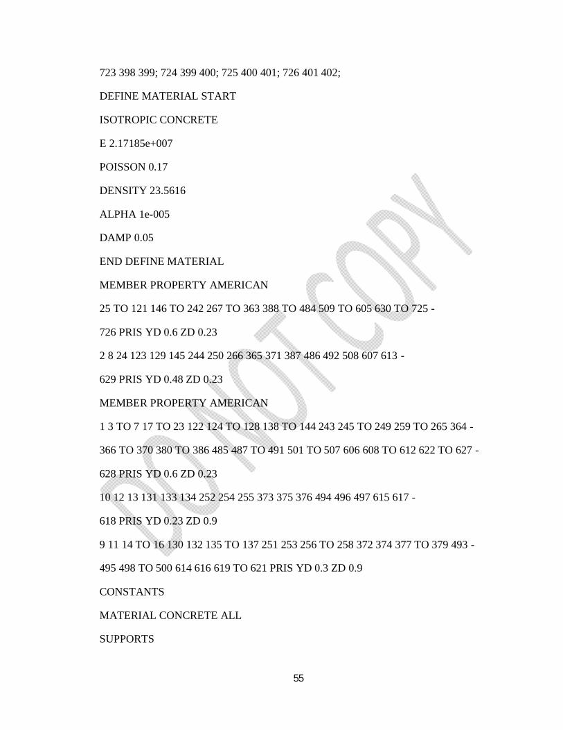
55
723 398 399; 724 399 400; 725 400 401; 726 401 402;
DEFINE MATERIAL START
ISOTROPIC CONCRETE
E 2.17185e+007
POISSON 0.17
DENSITY 23.5616
ALPHA 1e-005
DAMP 0.05
END DEFINE MATERIAL
MEMBER PROPERTY AMERICAN
25 TO 121 146 TO 242 267 TO 363 388 TO 484 509 TO 605 630 TO 725 -
726 PRIS YD 0.6 ZD 0.23
2 8 24 123 129 145 244 250 266 365 371 387 486 492 508 607 613 -
629 PRIS YD 0.48 ZD 0.23
MEMBER PROPERTY AMERICAN
1 3 TO 7 17 TO 23 122 124 TO 128 138 TO 144 243 245 TO 249 259 TO 265 364 -
366 TO 370 380 TO 386 485 487 TO 491 501 TO 507 606 608 TO 612 622 TO 627 -
628 PRIS YD 0.6 ZD 0.23
10 12 13 131 133 134 252 254 255 373 375 376 494 496 497 615 617 -
618 PRIS YD 0.23 ZD 0.9
9 11 14 TO 16 130 132 135 TO 137 251 253 256 TO 258 372 374 377 TO 379 493 -
495 498 TO 500 614 616 619 TO 621 PRIS YD 0.3 ZD 0.9
CONSTANTS
MATERIAL CONCRETE ALL
SUPPORTS
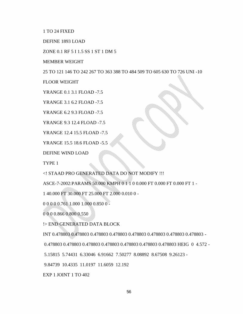
56
1 TO 24 FIXED
DEFINE 1893 LOAD
ZONE 0.1 RF 5 I 1.5 SS 1 ST 1 DM 5
MEMBER WEIGHT
25 TO 121 146 TO 242 267 TO 363 388 TO 484 509 TO 605 630 TO 726 UNI -10
FLOOR WEIGHT
YRANGE 0.1 3.1 FLOAD -7.5
YRANGE 3.1 6.2 FLOAD -7.5
YRANGE 6.2 9.3 FLOAD -7.5
YRANGE 9.3 12.4 FLOAD -7.5
YRANGE 12.4 15.5 FLOAD -7.5
YRANGE 15.5 18.6 FLOAD -5.5
DEFINE WIND LOAD
TYPE 1
<! STAAD PRO GENERATED DATA DO NOT MODIFY !!!
ASCE-7-2002:PARAMS 50.000 KMPH 0 1 1 0 0.000 FT 0.000 FT 0.000 FT 1 -
1 40.000 FT 30.000 FT 25.000 FT 2.000 0.010 0 -
0 0 0 0 0.761 1.000 1.000 0.850 0 -
0 0 0 0.866 0.800 0.550
!> END GENERATED DATA BLOCK
INT 0.478803 0.478803 0.478803 0.478803 0.478803 0.478803 0.478803 0.478803 -
0.478803 0.478803 0.478803 0.478803 0.478803 0.478803 0.478803 HEIG 0 4.572 -
5.15815 5.74431 6.33046 6.91662 7.50277 8.08892 8.67508 9.26123 -
9.84739 10.4335 11.0197 11.6059 12.192
EXP 1 JOINT 1 TO 402
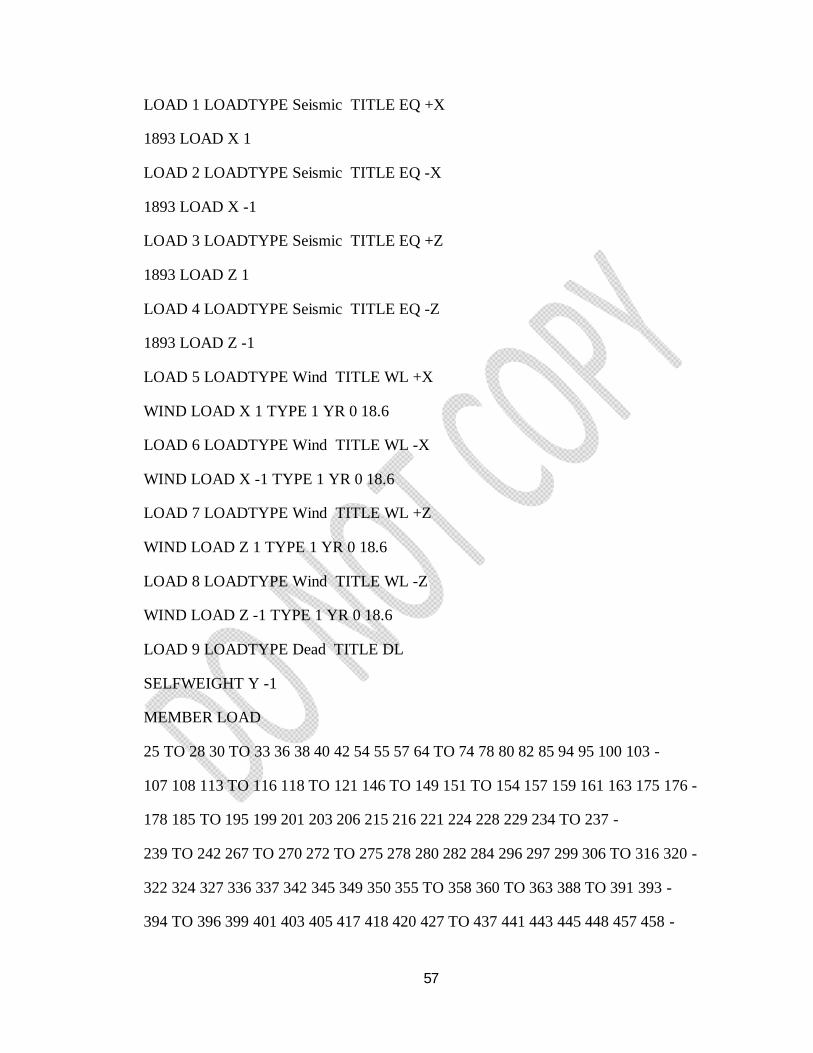
57
LOAD 1 LOADTYPE Seismic TITLE EQ +X
1893 LOAD X 1
LOAD 2 LOADTYPE Seismic TITLE EQ -X
1893 LOAD X -1
LOAD 3 LOADTYPE Seismic TITLE EQ +Z
1893 LOAD Z 1
LOAD 4 LOADTYPE Seismic TITLE EQ -Z
1893 LOAD Z -1
LOAD 5 LOADTYPE Wind TITLE WL +X
WIND LOAD X 1 TYPE 1 YR 0 18.6
LOAD 6 LOADTYPE Wind TITLE WL -X
WIND LOAD X -1 TYPE 1 YR 0 18.6
LOAD 7 LOADTYPE Wind TITLE WL +Z
WIND LOAD Z 1 TYPE 1 YR 0 18.6
LOAD 8 LOADTYPE Wind TITLE WL -Z
WIND LOAD Z -1 TYPE 1 YR 0 18.6
LOAD 9 LOADTYPE Dead TITLE DL
SELFWEIGHT Y -1
MEMBER LOAD
25 TO 28 30 TO 33 36 38 40 42 54 55 57 64 TO 74 78 80 82 85 94 95 100 103 -
107 108 113 TO 116 118 TO 121 146 TO 149 151 TO 154 157 159 161 163 175 176 -
178 185 TO 195 199 201 203 206 215 216 221 224 228 229 234 TO 237 -
239 TO 242 267 TO 270 272 TO 275 278 280 282 284 296 297 299 306 TO 316 320 -
322 324 327 336 337 342 345 349 350 355 TO 358 360 TO 363 388 TO 391 393 -
394 TO 396 399 401 403 405 417 418 420 427 TO 437 441 443 445 448 457 458 -
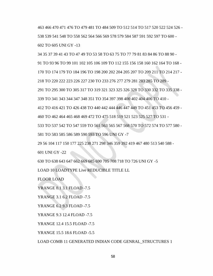
58
463 466 470 471 476 TO 479 481 TO 484 509 TO 512 514 TO 517 520 522 524 526 -
538 539 541 548 TO 558 562 564 566 569 578 579 584 587 591 592 597 TO 600 -
602 TO 605 UNI GY -13
34 35 37 39 41 43 TO 47 49 TO 53 58 TO 63 75 TO 77 79 81 83 84 86 TO 88 90 -
91 TO 93 96 TO 99 101 102 105 106 109 TO 112 155 156 158 160 162 164 TO 168 -
170 TO 174 179 TO 184 196 TO 198 200 202 204 205 207 TO 209 211 TO 214 217 -
218 TO 220 222 223 226 227 230 TO 233 276 277 279 281 283 285 TO 289 -
291 TO 295 300 TO 305 317 TO 319 321 323 325 326 328 TO 330 332 TO 335 338 -
339 TO 341 343 344 347 348 351 TO 354 397 398 400 402 404 406 TO 410 -
412 TO 416 421 TO 426 438 TO 440 442 444 446 447 449 TO 451 453 TO 456 459 -
460 TO 462 464 465 468 469 472 TO 475 518 519 521 523 525 527 TO 531 -
533 TO 537 542 TO 547 559 TO 561 563 565 567 568 570 TO 572 574 TO 577 580 -
581 TO 583 585 586 589 590 593 TO 596 UNI GY -7
29 56 104 117 150 177 225 238 271 298 346 359 392 419 467 480 513 540 588 -
601 UNI GY -22
630 TO 638 643 647 662 669 685 690 705 708 718 TO 726 UNI GY -5
LOAD 10 LOADTYPE Live REDUCIBLE TITLE LL
FLOOR LOAD
YRANGE 0.1 3.1 FLOAD -7.5
YRANGE 3.1 6.2 FLOAD -7.5
YRANGE 6.2 9.3 FLOAD -7.5
YRANGE 9.3 12.4 FLOAD -7.5
YRANGE 12.4 15.5 FLOAD -7.5
YRANGE 15.5 18.6 FLOAD -5.5
LOAD COMB 11 GENERATED INDIAN CODE GENRAL_STRUCTURES 1
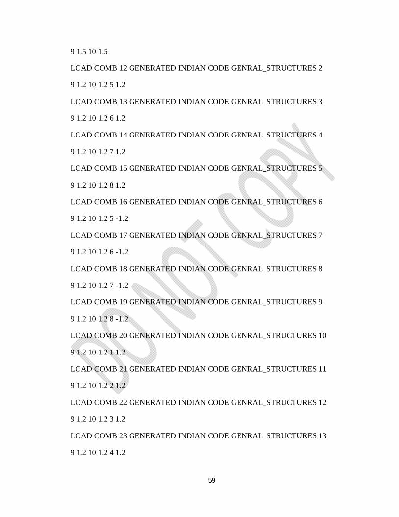
59
9 1.5 10 1.5
LOAD COMB 12 GENERATED INDIAN CODE GENRAL_STRUCTURES 2
9 1.2 10 1.2 5 1.2
LOAD COMB 13 GENERATED INDIAN CODE GENRAL_STRUCTURES 3
9 1.2 10 1.2 6 1.2
LOAD COMB 14 GENERATED INDIAN CODE GENRAL_STRUCTURES 4
9 1.2 10 1.2 7 1.2
LOAD COMB 15 GENERATED INDIAN CODE GENRAL_STRUCTURES 5
9 1.2 10 1.2 8 1.2
LOAD COMB 16 GENERATED INDIAN CODE GENRAL_STRUCTURES 6
9 1.2 10 1.2 5 -1.2
LOAD COMB 17 GENERATED INDIAN CODE GENRAL_STRUCTURES 7
9 1.2 10 1.2 6 -1.2
LOAD COMB 18 GENERATED INDIAN CODE GENRAL_STRUCTURES 8
9 1.2 10 1.2 7 -1.2
LOAD COMB 19 GENERATED INDIAN CODE GENRAL_STRUCTURES 9
9 1.2 10 1.2 8 -1.2
LOAD COMB 20 GENERATED INDIAN CODE GENRAL_STRUCTURES 10
9 1.2 10 1.2 1 1.2
LOAD COMB 21 GENERATED INDIAN CODE GENRAL_STRUCTURES 11
9 1.2 10 1.2 2 1.2
LOAD COMB 22 GENERATED INDIAN CODE GENRAL_STRUCTURES 12
9 1.2 10 1.2 3 1.2
LOAD COMB 23 GENERATED INDIAN CODE GENRAL_STRUCTURES 13
9 1.2 10 1.2 4 1.2
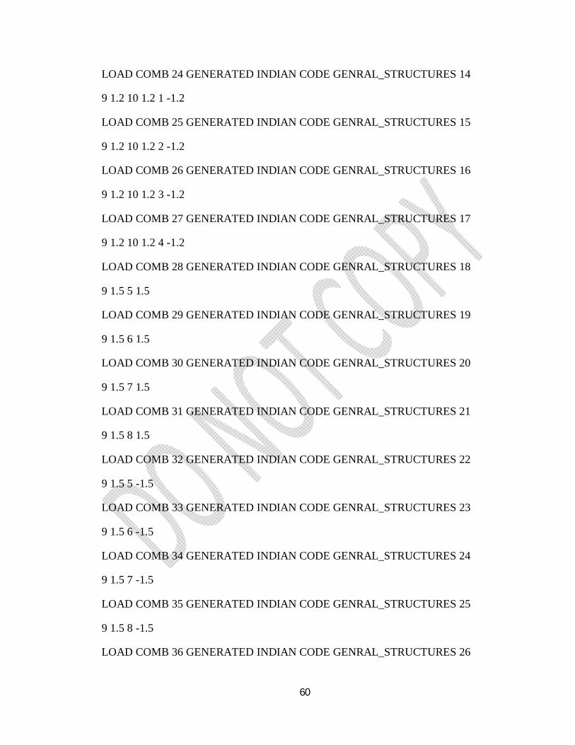
60
LOAD COMB 24 GENERATED INDIAN CODE GENRAL_STRUCTURES 14
9 1.2 10 1.2 1 -1.2
LOAD COMB 25 GENERATED INDIAN CODE GENRAL_STRUCTURES 15
9 1.2 10 1.2 2 -1.2
LOAD COMB 26 GENERATED INDIAN CODE GENRAL_STRUCTURES 16
9 1.2 10 1.2 3 -1.2
LOAD COMB 27 GENERATED INDIAN CODE GENRAL_STRUCTURES 17
9 1.2 10 1.2 4 -1.2
LOAD COMB 28 GENERATED INDIAN CODE GENRAL_STRUCTURES 18
9 1.5 5 1.5
LOAD COMB 29 GENERATED INDIAN CODE GENRAL_STRUCTURES 19
9 1.5 6 1.5
LOAD COMB 30 GENERATED INDIAN CODE GENRAL_STRUCTURES 20
9 1.5 7 1.5
LOAD COMB 31 GENERATED INDIAN CODE GENRAL_STRUCTURES 21
9 1.5 8 1.5
LOAD COMB 32 GENERATED INDIAN CODE GENRAL_STRUCTURES 22
9 1.5 5 -1.5
LOAD COMB 33 GENERATED INDIAN CODE GENRAL_STRUCTURES 23
9 1.5 6 -1.5
LOAD COMB 34 GENERATED INDIAN CODE GENRAL_STRUCTURES 24
9 1.5 7 -1.5
LOAD COMB 35 GENERATED INDIAN CODE GENRAL_STRUCTURES 25
9 1.5 8 -1.5
LOAD COMB 36 GENERATED INDIAN CODE GENRAL_STRUCTURES 26
61
9 1.5 1 1.5
LOAD COMB 37 GENERATED INDIAN CODE GENRAL_STRUCTURES 27
9 1.5 2 1.5
LOAD COMB 38 GENERATED INDIAN CODE GENRAL_STRUCTURES 28
9 1.5 3 1.5
LOAD COMB 39 GENERATED INDIAN CODE GENRAL_STRUCTURES 29
9 1.5 4 1.5
LOAD COMB 40 GENERATED INDIAN CODE GENRAL_STRUCTURES 30
9 1.5 1 -1.5
LOAD COMB 41 GENERATED INDIAN CODE GENRAL_STRUCTURES 31
9 1.5 2 -1.5
LOAD COMB 42 GENERATED INDIAN CODE GENRAL_STRUCTURES 32
9 1.5 3 -1.5
LOAD COMB 43 GENERATED INDIAN CODE GENRAL_STRUCTURES 33
9 1.5 4 -1.5
LOAD COMB 44 GENERATED INDIAN CODE GENRAL_STRUCTURES 34
9 0.9 1 1.5
LOAD COMB 45 GENERATED INDIAN CODE GENRAL_STRUCTURES 35
9 0.9 2 1.5
LOAD COMB 46 GENERATED INDIAN CODE GENRAL_STRUCTURES 36
9 0.9 3 1.5
LOAD COMB 47 GENERATED INDIAN CODE GENRAL_STRUCTURES 37
9 0.9 4 1.5
LOAD COMB 48 GENERATED INDIAN CODE GENRAL_STRUCTURES 38
9 0.9 1 -1.5
62
LOAD COMB 49 GENERATED INDIAN CODE GENRAL_STRUCTURES 39
9 0.9 2 -1.5
LOAD COMB 50 GENERATED INDIAN CODE GENRAL_STRUCTURES 40
9 0.9 3 -1.5
LOAD COMB 51 GENERATED INDIAN CODE GENRAL_STRUCTURES 41
9 0.9 4 -1.5
PERFORM ANALYSIS
LOAD LIST 11
PRINT SUPPORT REACTION ALL
PRINT MEMBER FORCES LIST 1 TO 24
START CONCRETE DESIGN
CODE INDIAN
FC 25000 ALL
FYMAIN 415000 ALL
FYSEC 415000 ALL
DESIGN COLUMN 1 TO 24
DESIGN BEAM 25 TO 121
CONCRETE TAKE
END CONCRETE DESIGN
FINISH
63
CHAPTER - 7
DESIGN OF SLABS, FOOTINGS AND
STAIRCASE
64
CHAPTER – 7
DESIGN OF SLABS, FOOTINGS AND STAIRCASE
7.1 DESIGN OF SLABS:
7.1.1 General:
Slabs are the plate elements forming floor and roof of building and carrying distributed
loads primarily by flexure. A slab is a flat, two-dimensional planar structural element
having a smaller thickness compared to its other two dimensions. It provides a working
flat surface or a covering shelter to buildings. It supports mainly transverse loads and
transfers them to supports primarily by bending action in one or more directions. Though
a RC slab is essentially a bending element, it differs from beam in the following aspects:
The bending cannot be only in one vertical plane as in case of beam but in more
than one vertical plane.
The slab is usually analyzed and designed, considering a strip of uniform length
Shear stresses are usually low and shear reinforcement is usually avoided in width
(usually 1m in practical design). Preference to increase in depth over the region
critical in shear.
Distribution steel provided at right angles to main steel in both the directions.
A reinforced concrete slab covers a relatively large area compared to a beam or column.
Therefore, volume of concrete and hence, dead load is large in case of slab. A small
reduction in the depth of slab therefore, leads to considerable economy. But, care has to
be taken to see that its performance (serviceability) is not affected due to excessive
deflection and cracking.
Depending on the direction of spacing (direction of distribution of loads), the slabs are
classified as following:
a. One way slabs and
b. Two way slabs
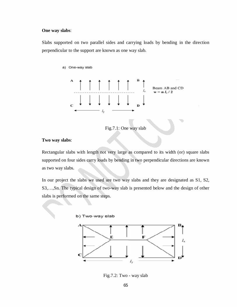
65
One way slabs:
Slabs supported on two parallel sides and carrying loads by bending in the direction
perpendicular to the support are known as one way slab.
Fig.7.1: One way slab
Two way slabs:
Rectangular slabs with length not very large as compared to its width (or) square slabs
supported on four sides carry loads by bending in two perpendicular directions are known
as two way slabs.
In our project the slabs we used are two way slabs and they are designated as S1, S2,
S3,…,Sn. The typical design of two-way slab is presented below and the design of other
slabs is performed on the same steps.
Fig.7.2: Two - way slab
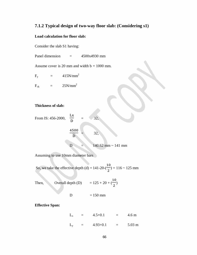
66
7.1.2 Typical design of two-way floor slab: (Considering s1)
Load calculation for floor slab:
Consider the slab S1 having:
Panel dimension = 4500x4930 mm
Assume cover is 20 mm and width b = 1000 mm.
Fy = 415N/mm2
Fck = 25N/mm2
Thickness of slab:
From IS: 456-2000, = 32,
= 32,
D = 140.62 mm ~ 141 mm
Assuming to use 10mm diameter bars
So, we take the effective depth (d) = 141-20-( ) = 116 ~ 125 mm
Then, Overall depth (D) = 125 + 20 + ( )
D = 150 mm
Effective Span:
Lx = 4.5+0.1 = 4.6 m
Ly = 4.93+0.1 = 5.03 m
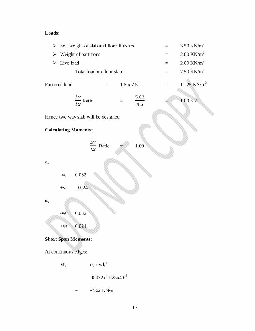
67
Loads:
Self weight of slab and floor finishes = 3.50 KN/m2
Weight of partitions = 2.00 KN/m2
Live load = 2.00 KN/m2
Total load on floor slab = 7.50 KN/m2
Factored load = 1.5 x 7.5 = 11.25 KN/m2
Ratio = ..
= 1.09 < 2
Hence two way slab will be designed.
Calculating Moments:
Ratio = 1.09
αx
-ve 0.032
+ve 0.024
αy
-ve 0.032
+ve 0.024
Short Span Moments:
At continuous edges:
Mx = αx x wlx2
= -0.032x11.25x4.62
= -7.62 KN-m
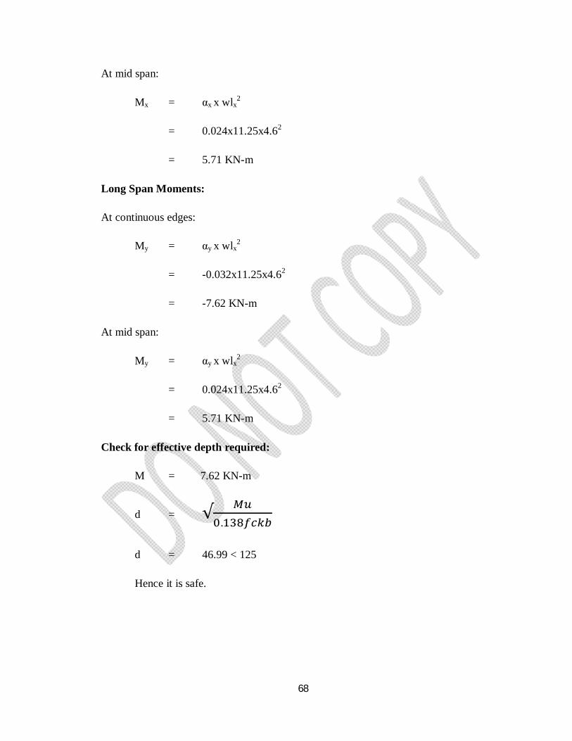
68
At mid span:
Mx = αx x wlx2
= 0.024x11.25x4.62
= 5.71 KN-m
Long Span Moments:
At continuous edges:
My = αy x wlx2
= -0.032x11.25x4.62
= -7.62 KN-m
At mid span:
My = αy x wlx2
= 0.024x11.25x4.62
= 5.71 KN-m
Check for effective depth required:
M = 7.62 KN-m
d = √.
d = 46.99 < 125
Hence it is safe.
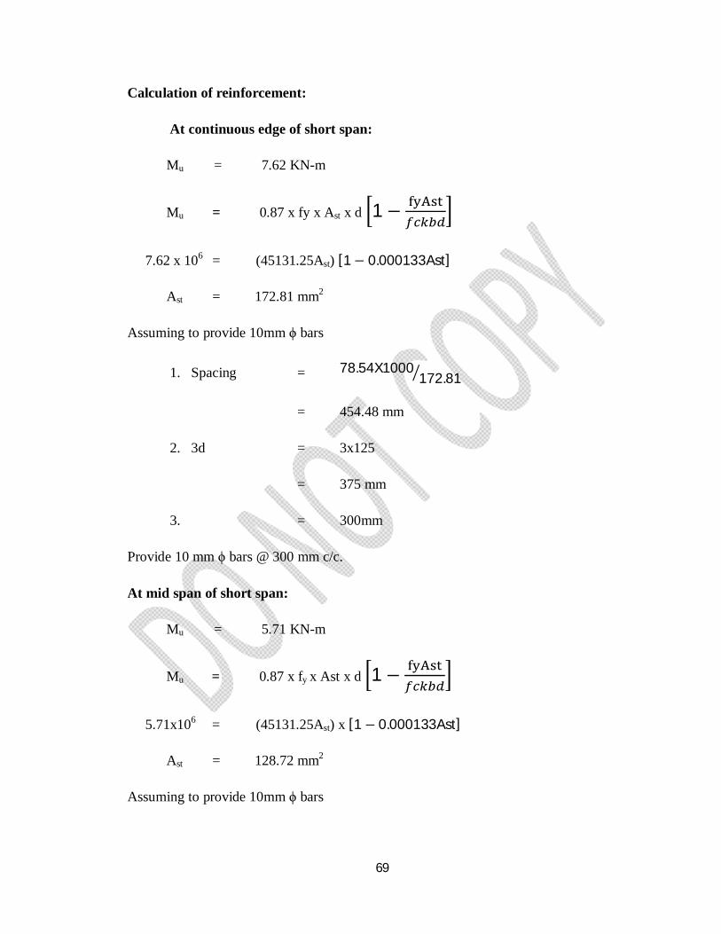
69
Calculation of reinforcement:
At continuous edge of short span:
Mu = 7.62 KN-m
Mu = 0.87 x fy x Ast x d 1 −
7.62 x 106 = (45131.25Ast) [1− 0.000133Ast]
Ast = 172.81 mm2
Assuming to provide 10mm ϕ bars
1. Spacing = 78.54X1000172.81
= 454.48 mm
2. 3d = 3x125
= 375 mm
3. = 300mm
Provide 10 mm ϕ bars @ 300 mm c/c.
At mid span of short span:
Mu = 5.71 KN-m
Mu = 0.87 x fy x Ast x d 1 −
5.71x106 = (45131.25Ast) x [1 − 0.000133Ast]
Ast = 128.72 mm2
Assuming to provide 10mm ϕ bars
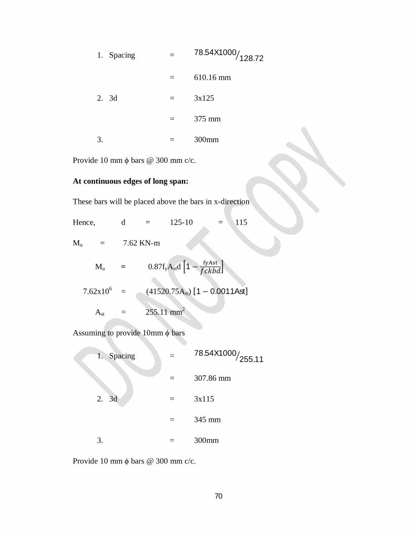
70
1. Spacing = 78.54X1000128.72
= 610.16 mm
2. 3d = 3x125
= 375 mm
3. = 300mm
Provide 10 mm ϕ bars @ 300 mm c/c.
At continuous edges of long span:
These bars will be placed above the bars in x-direction
Hence, d = 125-10 = 115
Mu = 7.62 KN-m
Mu = 0.87fyAstd 1 − 푓푐푘푏푑
7.62x106 = (41520.75Ast) [1− 0.0011Ast]
Ast = 255.11 mm2
Assuming to provide 10mm ϕ bars
1. Spacing = 78.54X1000255.11
= 307.86 mm
2. 3d = 3x115
= 345 mm
3. = 300mm
Provide 10 mm ϕ bars @ 300 mm c/c.
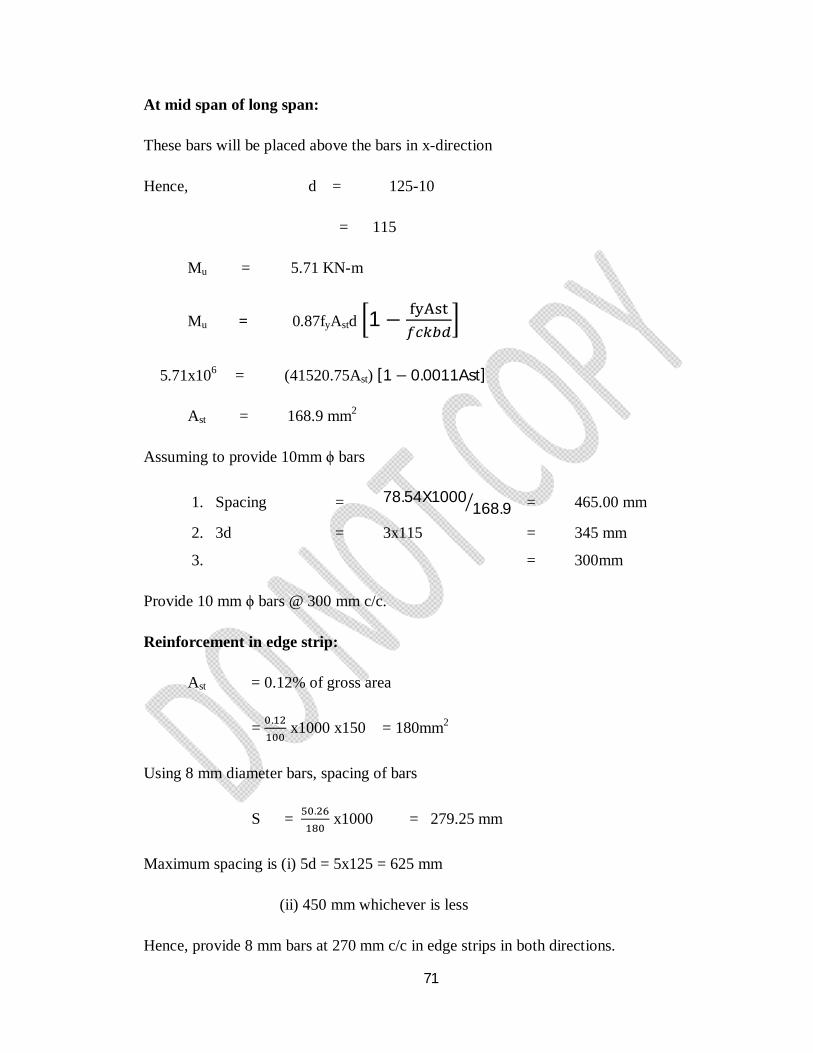
71
At mid span of long span:
These bars will be placed above the bars in x-direction
Hence, d = 125-10
= 115
Mu = 5.71 KN-m
Mu = 0.87fyAstd 1 −
5.71x106 = (41520.75Ast) [1 − 0.0011Ast]
Ast = 168.9 mm2
Assuming to provide 10mm ϕ bars
1. Spacing = 78.54X1000168.9 = 465.00 mm
2. 3d = 3x115 = 345 mm
3. = 300mm
Provide 10 mm ϕ bars @ 300 mm c/c.
Reinforcement in edge strip:
Ast = 0.12% of gross area
= . x1000 x150 = 180mm2
Using 8 mm diameter bars, spacing of bars
S = . x1000 = 279.25 mm
Maximum spacing is (i) 5d = 5x125 = 625 mm
(ii) 450 mm whichever is less
Hence, provide 8 mm bars at 270 mm c/c in edge strips in both directions.
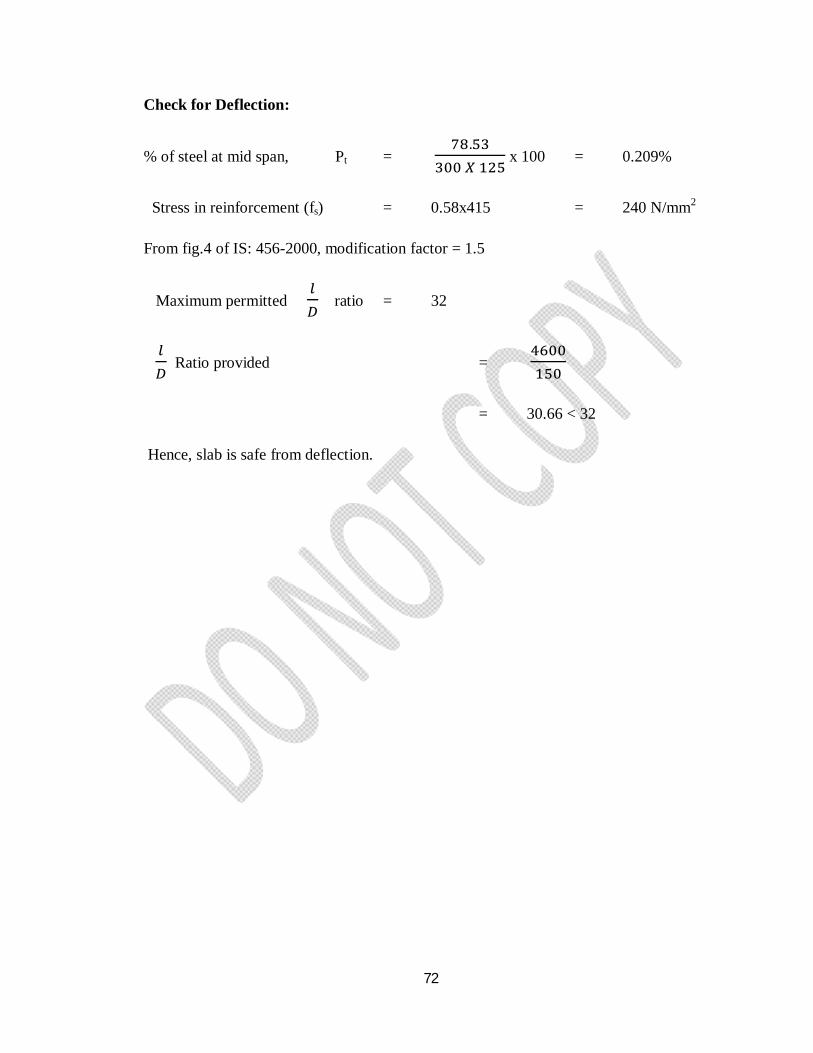
72
Check for Deflection:
% of steel at mid span, Pt = .
x 100 = 0.209%
Stress in reinforcement (fs) = 0.58x415 = 240 N/mm2
From fig.4 of IS: 456-2000, modification factor = 1.5
Maximum permitted ratio = 32
Ratio provided =
= 30.66 < 32
Hence, slab is safe from deflection.
73
7.2 DESIGN OF FOOTINGS:
7.2.1 General:
Footing is the bottom most but the most important compound of a structure which lies
before the ground level it has to be well planned and carefully designed to ensure the
safety and stability of the structure the function of the footing is to safely transfer loads
from the super structure to the ground.
Footing under walls are called one way footings and those under columns are two way
footings present we designed two way footings.
The safe bearing capacity (S.B.C) of a soil is taken as 200 KN/m2 and the materials used
are M25 grade concrete and Fe 415 steel. The weight of the footing is taken as 10% of
load.
The depth of the footing is calculated by bending moment consideration and checked for
one way and two way shear.
Type of footing designed as isolated sloped footing.
Depth of the footing required:
In case of sloped footings cross-section along x-x and y-y axis which resists maximum
bending moment is a combination of rectangular and trapezium. The depth of the cross-
section is maximum at the base of the column and minimum at the free edge. At the same
time at top width of the section is increasing from a minimum value near the column face
to the maximum value of the free ends.
Because of this variation in depth and breadth it is difficult to arrive at an expression for
moment at resistance in terms of breadth and depth. Hence for simplifying the process of
analysis and equivalent rectangular section of width equal to the width of the column.
1/6th of projection and depth is equal to the maximum depth of the footing near the face
of the column.
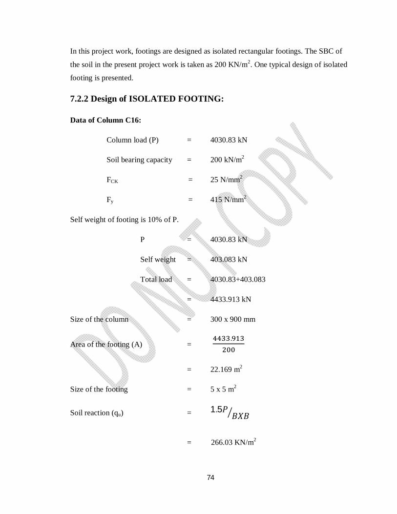
74
In this project work, footings are designed as isolated rectangular footings. The SBC of
the soil in the present project work is taken as 200 KN/m2. One typical design of isolated
footing is presented.
7.2.2 Design of ISOLATED FOOTING:
Data of Column C16:
Column load (P) = 4030.83 kN
Soil bearing capacity = 200 kN/m2
FCK = 25 N/mm2
Fy = 415 N/mm2
Self weight of footing is 10% of P.
P = 4030.83 kN
Self weight = 403.083 kN
Total load = 4030.83+403.083
= 4433.913 kN
Size of the column = 300 x 900 mm
Area of the footing (A) = .
= 22.169 m2
Size of the footing = 5 x 5 m2
Soil reaction (qu) = 1.5푃퐵푋퐵
= 266.03 KN/m2
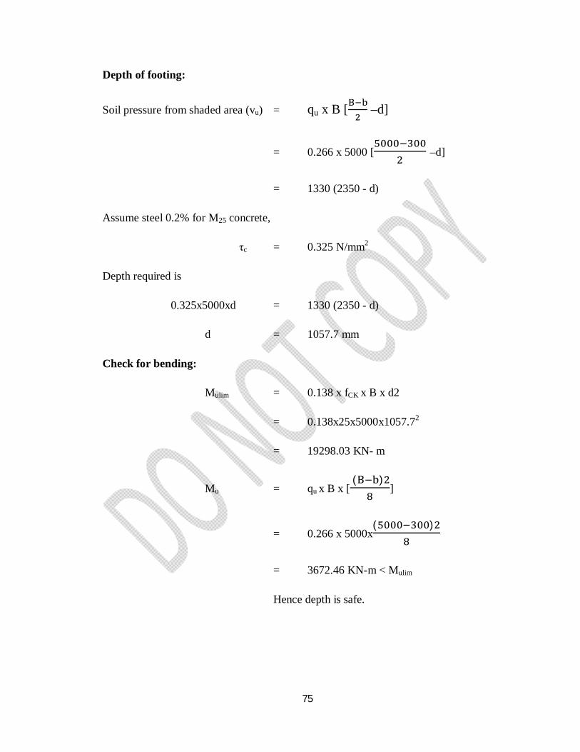
75
Depth of footing:
Soil pressure from shaded area (vu) = qu x B [ –d]
= 0.266 x 5000 [ –d]
= 1330 (2350 - d)
Assume steel 0.2% for M25 concrete,
τc = 0.325 N/mm2
Depth required is
0.325x5000xd = 1330 (2350 - d)
d = 1057.7 mm
Check for bending:
Mulim = 0.138 x fCK x B x d2
= 0.138x25x5000x1057.72
= 19298.03 KN- m
Mu = qu x B x [ ( )
]
= 0.266 x 5000x( )
= 3672.46 KN-m < Mulim
Hence depth is safe.
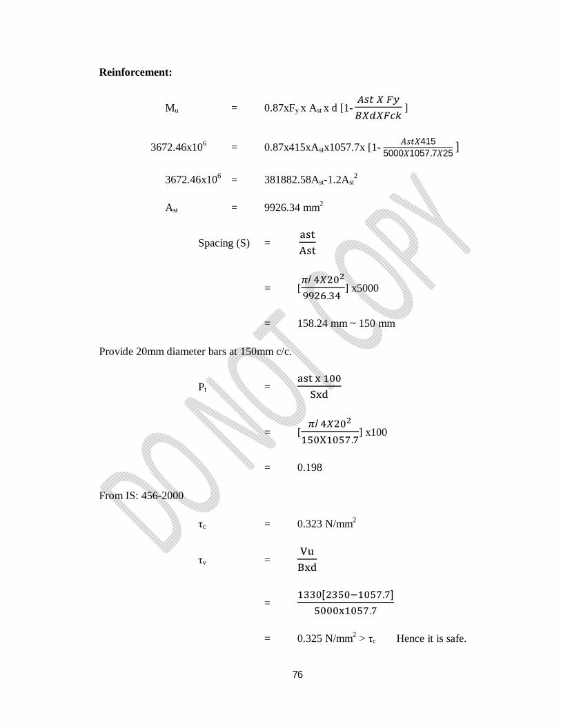
76
Reinforcement:
Mu = 0.87xFy x Ast x d [1-
]
3672.46x106 = 0.87x415xAstx1057.7x [1- 퐴푠푡푋4155000푋1057.7푋25 ]
3672.46x106 = 381882.58Ast-1.2Ast2
Ast = 9926.34 mm2
Spacing (S) =
= [/
. ] x5000
= 158.24 mm ~ 150 mm
Provide 20mm diameter bars at 150mm c/c.
Pt =
= [/
.] x100
= 0.198
From IS: 456-2000
τc = 0.323 N/mm2
τv =
= [ . ]
.
= 0.325 N/mm2 > τc Hence it is safe.

77
Development length:
Ld = .
= .
. .
= 940.23 m.
78
7.3 DESIGN OF STAIRCASE: 7.3.1 General:
Staircase is a space where steps for going (rising) from one floor (height) to another are
arranged systematically in stairs (flights). A staircase may be of different types depending
upon the available space, convenience of users, architectural considerations, etc.
Functionally, staircase is an important component of a building, and often the only means
of access between the various floors in the building. It consists of flights of steps, usually
with one or more intermediate landings (horizontal slab platforms) provided between the
floor levels. The horizontal top portion of a step (where the foot rests) is termed thread
and the vertical projection of the step (i.e., the vertical distance between two neighboring
steps) is called riser.
Usually, the staircase may be provided near the main entrance of the building. All
staircases should be adequately ventilated and properly designed.
Types of stair cases:
a) Straight stairs
b) Dog-legged stairs
c) Open-well stair case
d) Geometric staircase
The loads on the landing could be taken equal to that on the steps but should distribute
equally. This load distribution is usually idealized as uniform over the entire span as done
in the case of slabs.
The head room, i.e. the height between parallel flights or the height between a floor and
landing, must be sufficient so that user may not have any difficulty either in going or
carrying useful furniture’s, luggage’s, etc. Minimum headroom of 2.1 m is essential.
The width of a flight shall not be less than 0.9 m so that users crossing each other on a
step may not collide. The maximum width may be fixed depending on traffic and other
considerations.
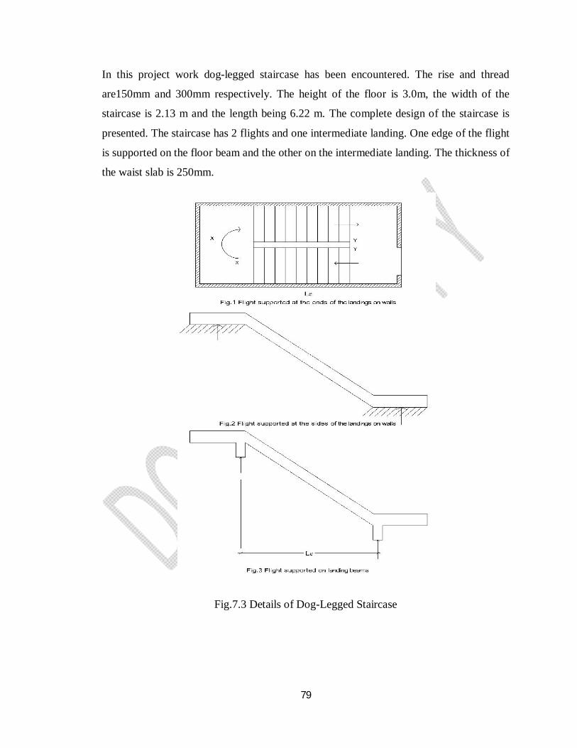
79
In this project work dog-legged staircase has been encountered. The rise and thread
are150mm and 300mm respectively. The height of the floor is 3.0m, the width of the
staircase is 2.13 m and the length being 6.22 m. The complete design of the staircase is
presented. The staircase has 2 flights and one intermediate landing. One edge of the flight
is supported on the floor beam and the other on the intermediate landing. The thickness of
the waist slab is 250mm.
Fig.7.3 Details of Dog-Legged Staircase
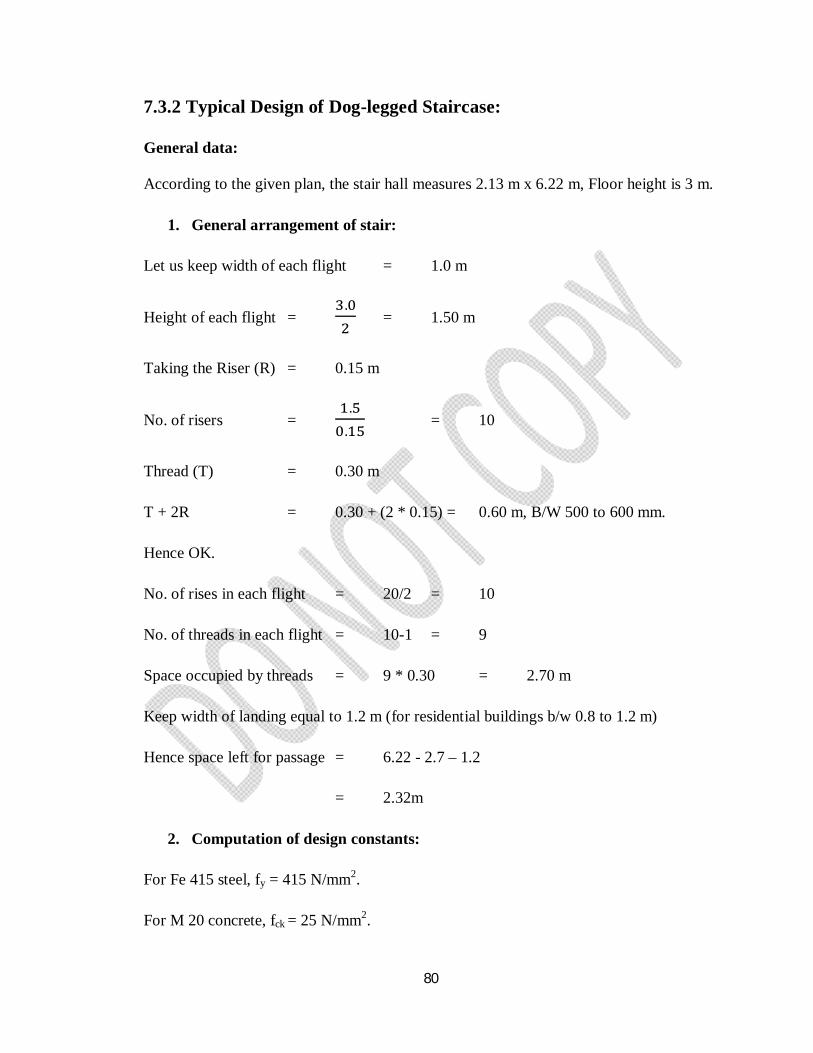
80
7.3.2 Typical Design of Dog-legged Staircase:
General data:
According to the given plan, the stair hall measures 2.13 m x 6.22 m, Floor height is 3 m.
1. General arrangement of stair:
Let us keep width of each flight = 1.0 m
Height of each flight = . = 1.50 m
Taking the Riser (R) = 0.15 m
No. of risers = .
. = 10
Thread (T) = 0.30 m
T + 2R = 0.30 + (2 * 0.15) = 0.60 m, B/W 500 to 600 mm.
Hence OK.
No. of rises in each flight = 20/2 = 10
No. of threads in each flight = 10-1 = 9
Space occupied by threads = 9 * 0.30 = 2.70 m
Keep width of landing equal to 1.2 m (for residential buildings b/w 0.8 to 1.2 m)
Hence space left for passage = 6.22 - 2.7 – 1.2
= 2.32m
2. Computation of design constants:
For Fe 415 steel, fy = 415 N/mm2.
For M 20 concrete, fck = 25 N/mm2.
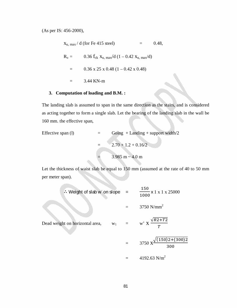
81
(As per IS: 456-2000),
xu, max / d (for Fe 415 steel) = 0.48,
Ru = 0.36 fck xu, max/d (1 – 0.42 xu, max/d)
= 0.36 x 25 x 0.48 (1 – 0.42 x 0.48)
= 3.44 KN-m
3. Computation of loading and B.M. :
The landing slab is assumed to span in the same direction as the stairs, and is considered
as acting together to form a single slab. Let the bearing of the landing slab in the wall be
160 mm. the effective span,
Effective span (l) = Going + Landing + support width/2
= 2.70 + 1.2 + 0.16/2
= 3.985 m ~ 4.0 m
Let the thickness of waist slab be equal to 150 mm (assumed at the rate of 40 to 50 mm
per meter span).
∴ Weight of slab w' on slope = x 1 x 1 x 25000
= 3750 N/mm2
Dead weight on horizontal area, w1 = w’ x √
= 3750 x ( ) ( )
= 4192.63 N/m2
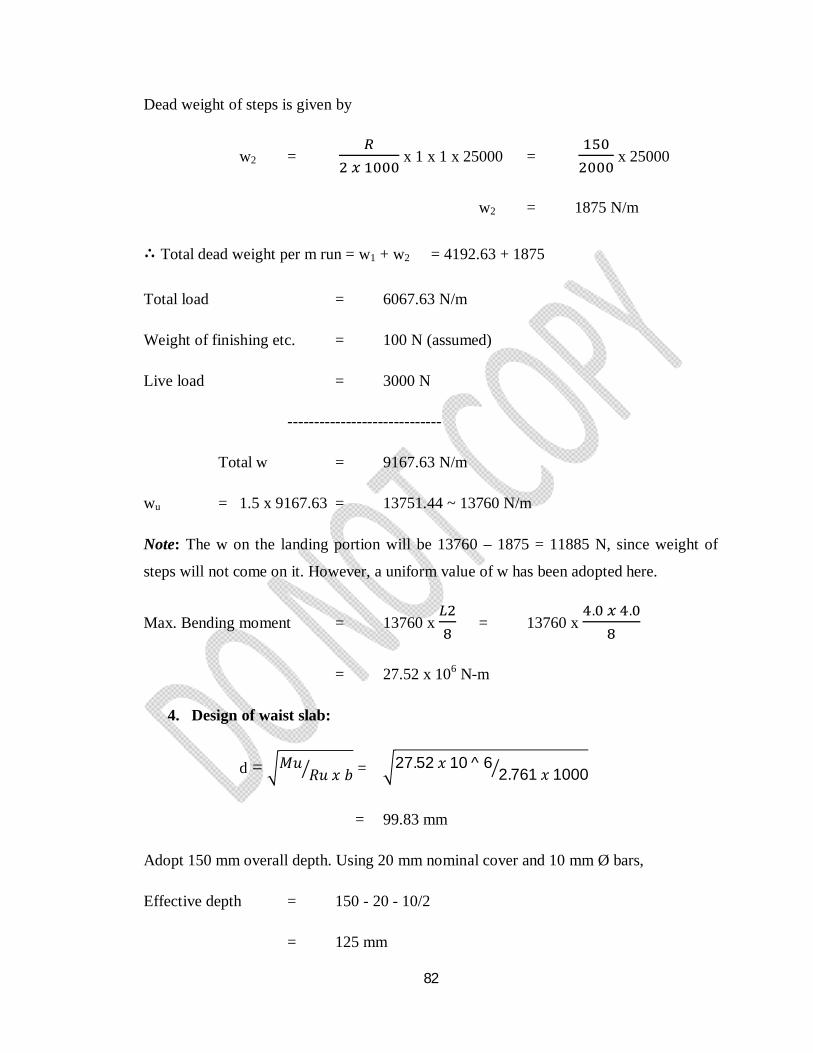
82
Dead weight of steps is given by
w2 =
x 1 x 1 x 25000 = x 25000
w2 = 1875 N/m
∴ Total dead weight per m run = w1 + w2 = 4192.63 + 1875
Total load = 6067.63 N/m
Weight of finishing etc. = 100 N (assumed)
Live load = 3000 N
-----------------------------
Total w = 9167.63 N/m
wu = 1.5 x 9167.63 = 13751.44 ~ 13760 N/m
Note: The w on the landing portion will be 13760 – 1875 = 11885 N, since weight of
steps will not come on it. However, a uniform value of w has been adopted here.
Max. Bending moment = 13760 x = 13760 x . .
= 27.52 x 10⁶ N-m
4. Design of waist slab:
d = 푀푢푅푢 푥 푏 = 27.52 푥 10 ^ 6
2.761 푥 1000
= 99.83 mm
Adopt 150 mm overall depth. Using 20 mm nominal cover and 10 mm Ø bars,
Effective depth = 150 - 20 - 10/2
= 125 mm
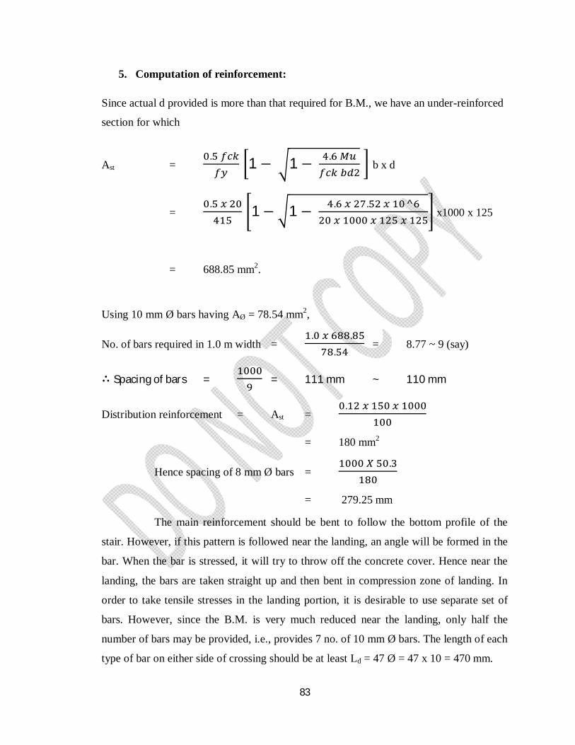
83
5. Computation of reinforcement:
Since actual d provided is more than that required for B.M., we have an under-reinforced
section for which
Ast = . 1 − 1 − .
b x d
= . 1− 1 − . . ^
x1000 x 125
= 688.85 mm2.
Using 10 mm Ø bars having AØ = 78.54 mm2,
No. of bars required in 1.0 m width = . .
. = 8.77 ~ 9 (say)
∴ Spacing of bars = = 111 mm ~ 110 mm
Distribution reinforcement = Ast = .
= 180 mm2
Hence spacing of 8 mm Ø bars = .
= 279.25 mm
The main reinforcement should be bent to follow the bottom profile of the
stair. However, if this pattern is followed near the landing, an angle will be formed in the
bar. When the bar is stressed, it will try to throw off the concrete cover. Hence near the
landing, the bars are taken straight up and then bent in compression zone of landing. In
order to take tensile stresses in the landing portion, it is desirable to use separate set of
bars. However, since the B.M. is very much reduced near the landing, only half the
number of bars may be provided, i.e., provides 7 no. of 10 mm Ø bars. The length of each
type of bar on either side of crossing should be at least Ld = 47 Ø = 47 x 10 = 470 mm.

84
CHAPTER - 8
ANALYSIS AND DESIGN RESULTS
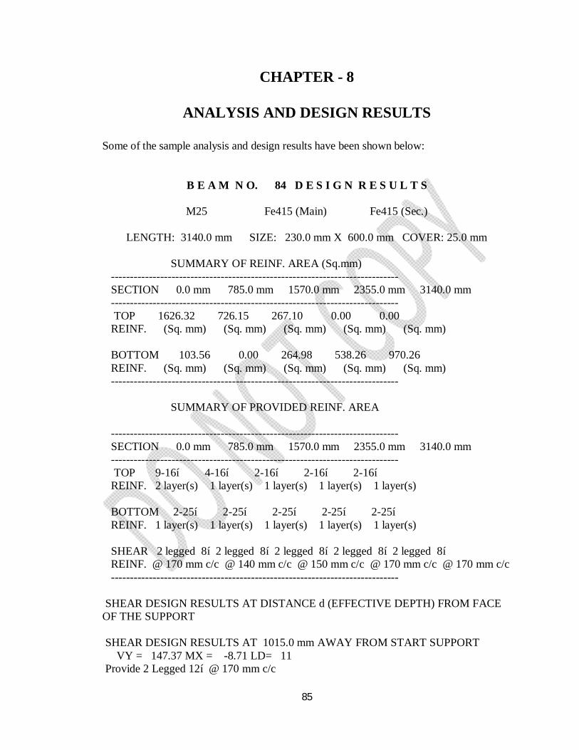
85
CHAPTER - 8
ANALYSIS AND DESIGN RESULTS
Some of the sample analysis and design results have been shown below:
B E A M N O. 84 D E S I G N R E S U L T S
M25 Fe415 (Main) Fe415 (Sec.)
LENGTH: 3140.0 mm SIZE: 230.0 mm X 600.0 mm COVER: 25.0 mm SUMMARY OF REINF. AREA (Sq.mm) ---------------------------------------------------------------------------- SECTION 0.0 mm 785.0 mm 1570.0 mm 2355.0 mm 3140.0 mm ---------------------------------------------------------------------------- TOP 1626.32 726.15 267.10 0.00 0.00 REINF. (Sq. mm) (Sq. mm) (Sq. mm) (Sq. mm) (Sq. mm) BOTTOM 103.56 0.00 264.98 538.26 970.26 REINF. (Sq. mm) (Sq. mm) (Sq. mm) (Sq. mm) (Sq. mm) ---------------------------------------------------------------------------- SUMMARY OF PROVIDED REINF. AREA ---------------------------------------------------------------------------- SECTION 0.0 mm 785.0 mm 1570.0 mm 2355.0 mm 3140.0 mm ---------------------------------------------------------------------------- TOP 9-16í 4-16í 2-16í 2-16í 2-16í REINF. 2 layer(s) 1 layer(s) 1 layer(s) 1 layer(s) 1 layer(s) BOTTOM 2-25í 2-25í 2-25í 2-25í 2-25í REINF. 1 layer(s) 1 layer(s) 1 layer(s) 1 layer(s) 1 layer(s) SHEAR 2 legged 8í 2 legged 8í 2 legged 8í 2 legged 8í 2 legged 8í REINF. @ 170 mm c/c @ 140 mm c/c @ 150 mm c/c @ 170 mm c/c @ 170 mm c/c ---------------------------------------------------------------------------- SHEAR DESIGN RESULTS AT DISTANCE d (EFFECTIVE DEPTH) FROM FACE OF THE SUPPORT SHEAR DESIGN RESULTS AT 1015.0 mm AWAY FROM START SUPPORT VY = 147.37 MX = -8.71 LD= 11 Provide 2 Legged 12í @ 170 mm c/c
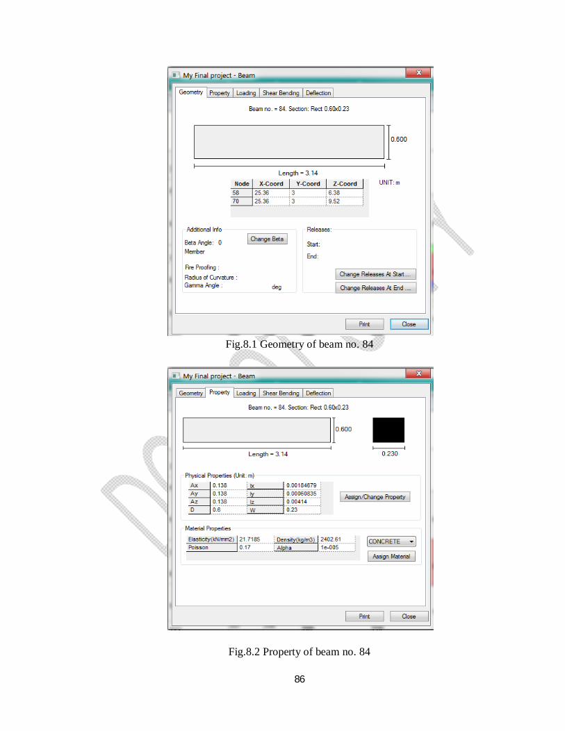
86
Fig.8.1 Geometry of beam no. 84
Fig.8.2 Property of beam no. 84
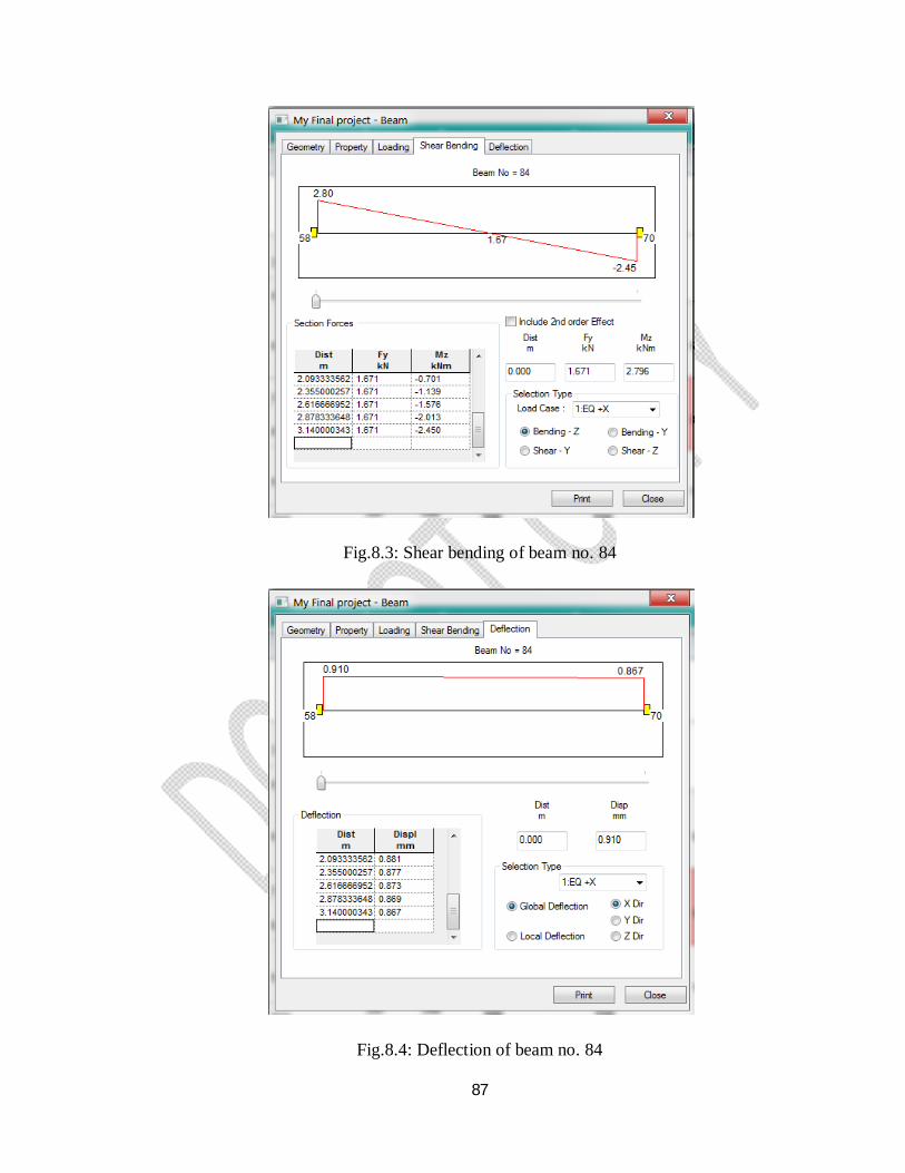
87
Fig.8.3: Shear bending of beam no. 84
Fig.8.4: Deflection of beam no. 84
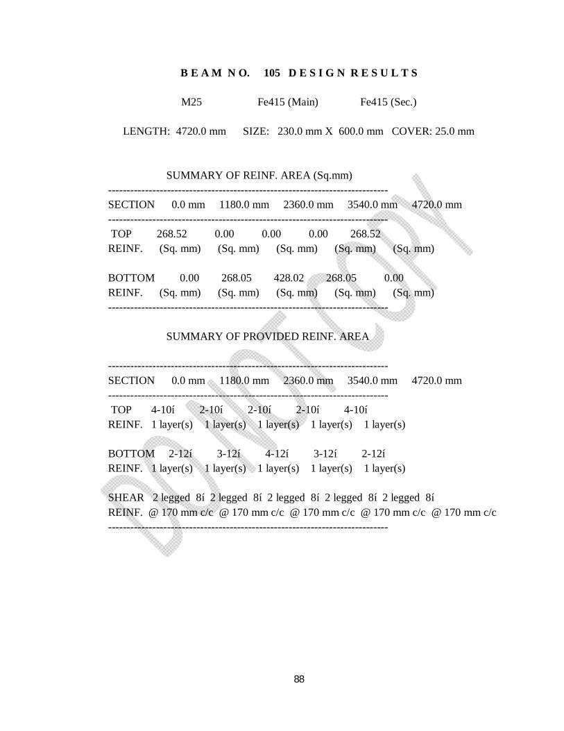
88
B E A M N O. 105 D E S I G N R E S U L T S
M25 Fe415 (Main) Fe415 (Sec.)
LENGTH: 4720.0 mm SIZE: 230.0 mm X 600.0 mm COVER: 25.0 mm SUMMARY OF REINF. AREA (Sq.mm) ---------------------------------------------------------------------------- SECTION 0.0 mm 1180.0 mm 2360.0 mm 3540.0 mm 4720.0 mm ---------------------------------------------------------------------------- TOP 268.52 0.00 0.00 0.00 268.52 REINF. (Sq. mm) (Sq. mm) (Sq. mm) (Sq. mm) (Sq. mm) BOTTOM 0.00 268.05 428.02 268.05 0.00 REINF. (Sq. mm) (Sq. mm) (Sq. mm) (Sq. mm) (Sq. mm) ---------------------------------------------------------------------------- SUMMARY OF PROVIDED REINF. AREA ---------------------------------------------------------------------------- SECTION 0.0 mm 1180.0 mm 2360.0 mm 3540.0 mm 4720.0 mm ---------------------------------------------------------------------------- TOP 4-10í 2-10í 2-10í 2-10í 4-10í REINF. 1 layer(s) 1 layer(s) 1 layer(s) 1 layer(s) 1 layer(s) BOTTOM 2-12í 3-12í 4-12í 3-12í 2-12í REINF. 1 layer(s) 1 layer(s) 1 layer(s) 1 layer(s) 1 layer(s) SHEAR 2 legged 8í 2 legged 8í 2 legged 8í 2 legged 8í 2 legged 8í REINF. @ 170 mm c/c @ 170 mm c/c @ 170 mm c/c @ 170 mm c/c @ 170 mm c/c ----------------------------------------------------------------------------
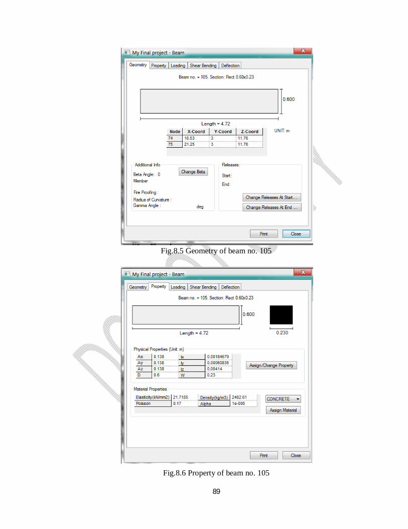
89
Fig.8.5 Geometry of beam no. 105
Fig.8.6 Property of beam no. 105
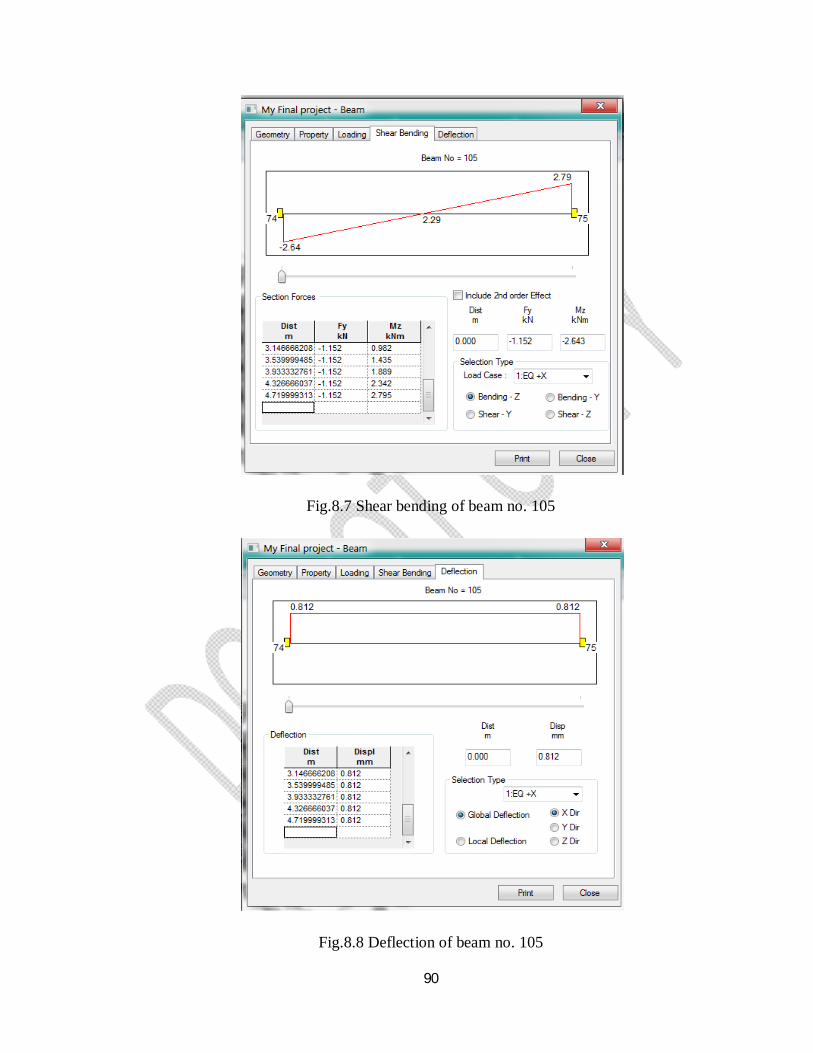
90
Fig.8.7 Shear bending of beam no. 105
Fig.8.8 Deflection of beam no. 105
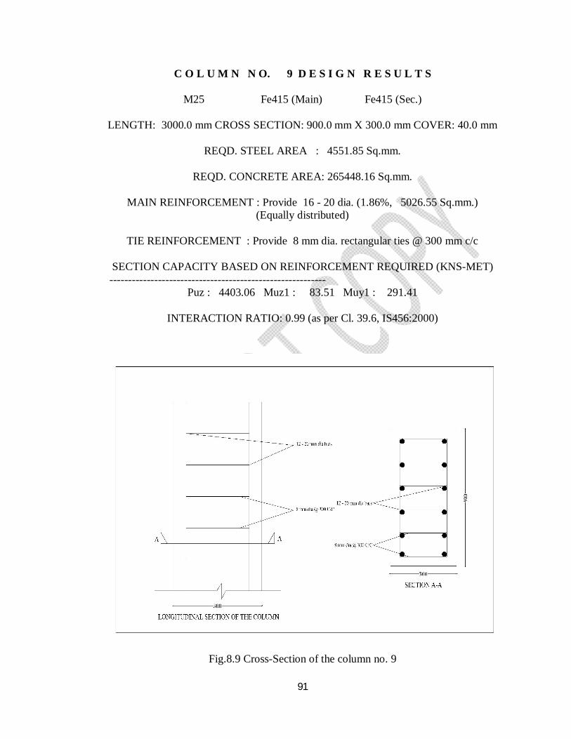
91
C O L U M N N O. 9 D E S I G N R E S U L T S
M25 Fe415 (Main) Fe415 (Sec.)
LENGTH: 3000.0 mm CROSS SECTION: 900.0 mm X 300.0 mm COVER: 40.0 mm
REQD. STEEL AREA : 4551.85 Sq.mm.
REQD. CONCRETE AREA: 265448.16 Sq.mm.
MAIN REINFORCEMENT : Provide 16 - 20 dia. (1.86%, 5026.55 Sq.mm.) (Equally distributed)
TIE REINFORCEMENT : Provide 8 mm dia. rectangular ties @ 300 mm c/c
SECTION CAPACITY BASED ON REINFORCEMENT REQUIRED (KNS-MET)
---------------------------------------------------------- Puz : 4403.06 Muz1 : 83.51 Muy1 : 291.41
INTERACTION RATIO: 0.99 (as per Cl. 39.6, IS456:2000)
Fig.8.9 Cross-Section of the column no. 9
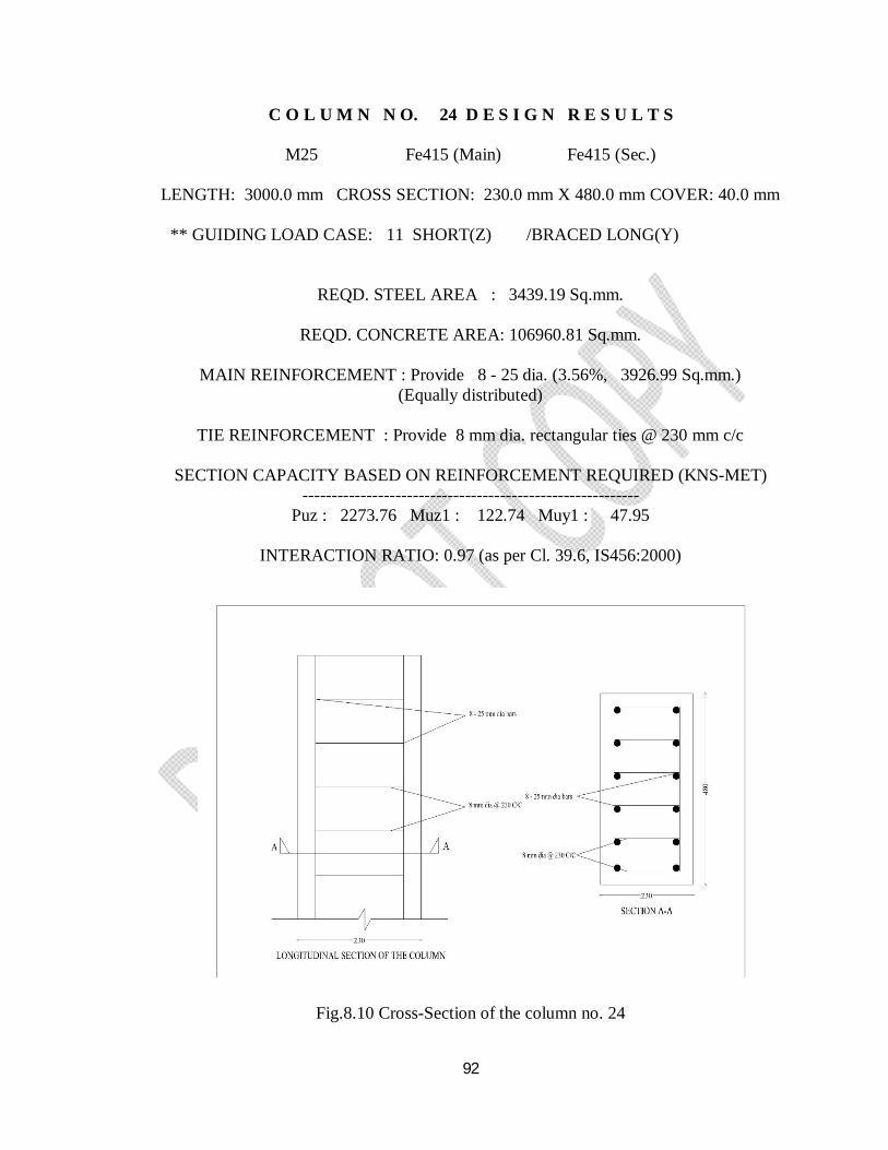
92
C O L U M N N O. 24 D E S I G N R E S U L T S
M25 Fe415 (Main) Fe415 (Sec.)
LENGTH: 3000.0 mm CROSS SECTION: 230.0 mm X 480.0 mm COVER: 40.0 mm ** GUIDING LOAD CASE: 11 SHORT(Z) /BRACED LONG(Y)
REQD. STEEL AREA : 3439.19 Sq.mm.
REQD. CONCRETE AREA: 106960.81 Sq.mm.
MAIN REINFORCEMENT : Provide 8 - 25 dia. (3.56%, 3926.99 Sq.mm.) (Equally distributed)
TIE REINFORCEMENT : Provide 8 mm dia. rectangular ties @ 230 mm c/c
SECTION CAPACITY BASED ON REINFORCEMENT REQUIRED (KNS-MET)
---------------------------------------------------------- Puz : 2273.76 Muz1 : 122.74 Muy1 : 47.95
INTERACTION RATIO: 0.97 (as per Cl. 39.6, IS456:2000)
Fig.8.10 Cross-Section of the column no. 24

93
POST PROCESSING MODE
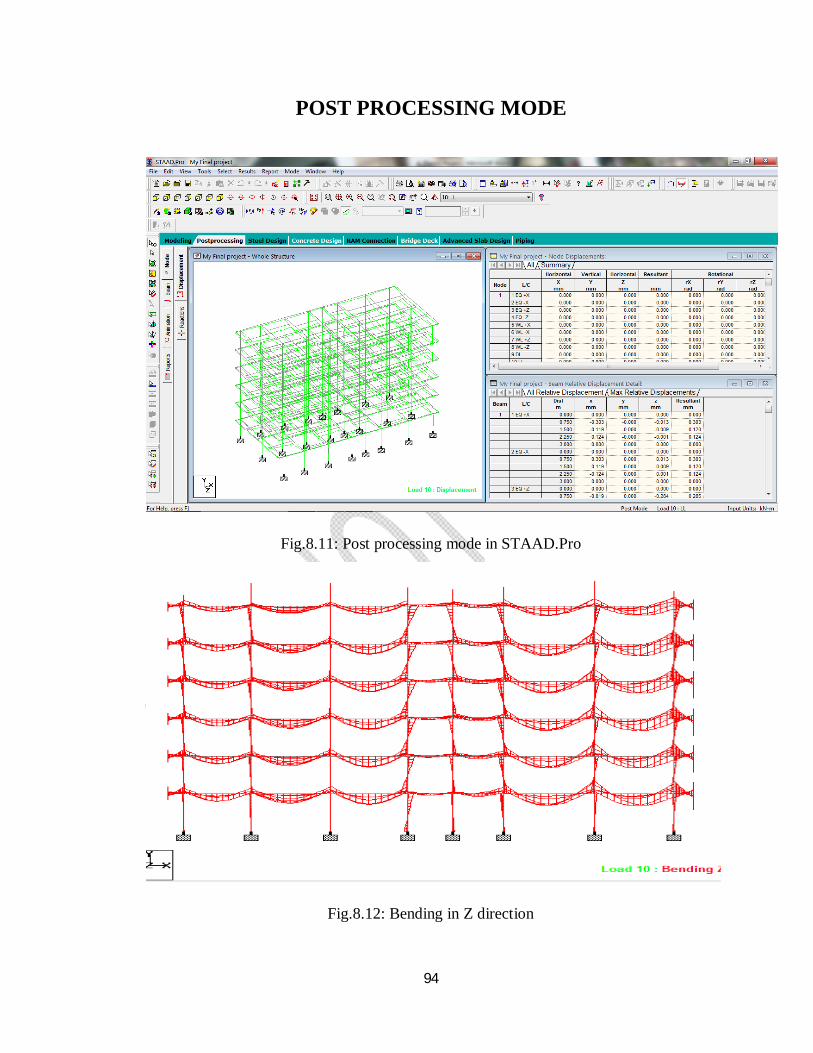
94
POST PROCESSING MODE
Fig.8.11: Post processing mode in STAAD.Pro
Fig.8.12: Bending in Z direction
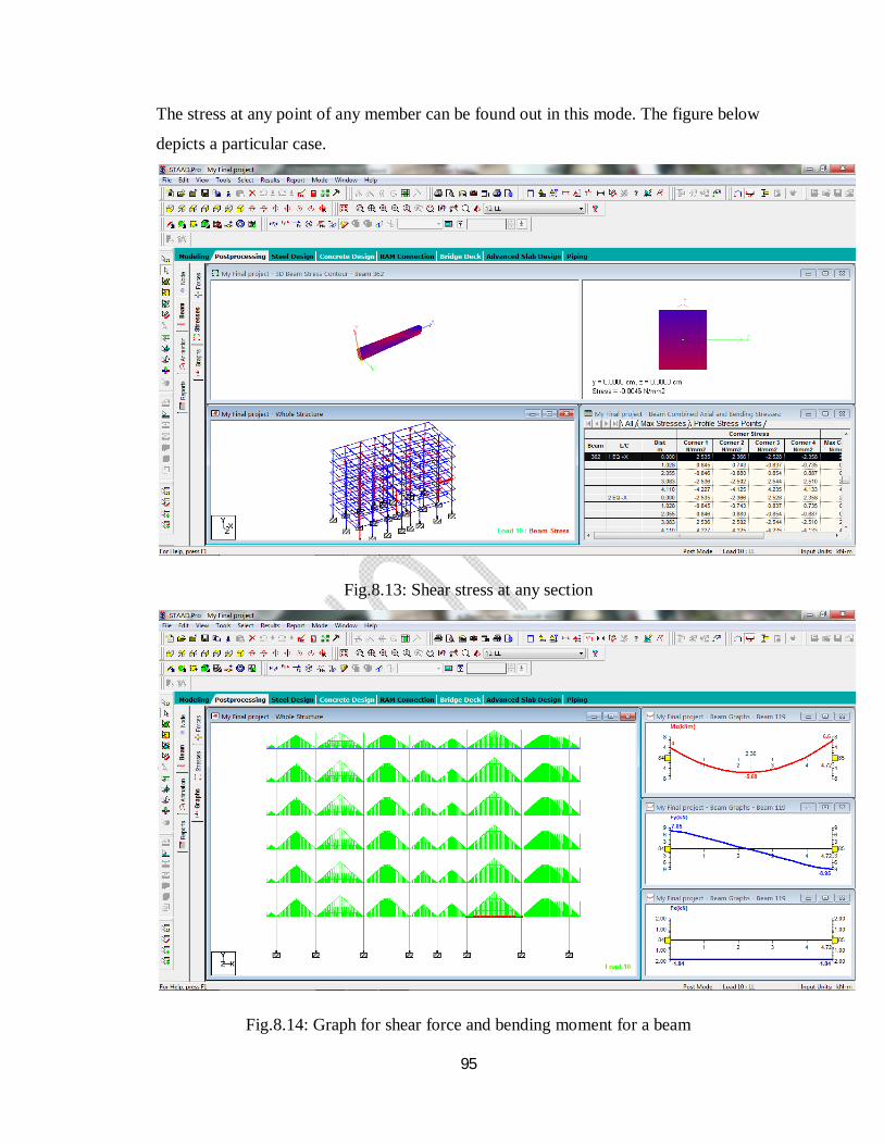
95
The stress at any point of any member can be found out in this mode. The figure below
depicts a particular case.
Fig.8.13: Shear stress at any section
Fig.8.14: Graph for shear force and bending moment for a beam
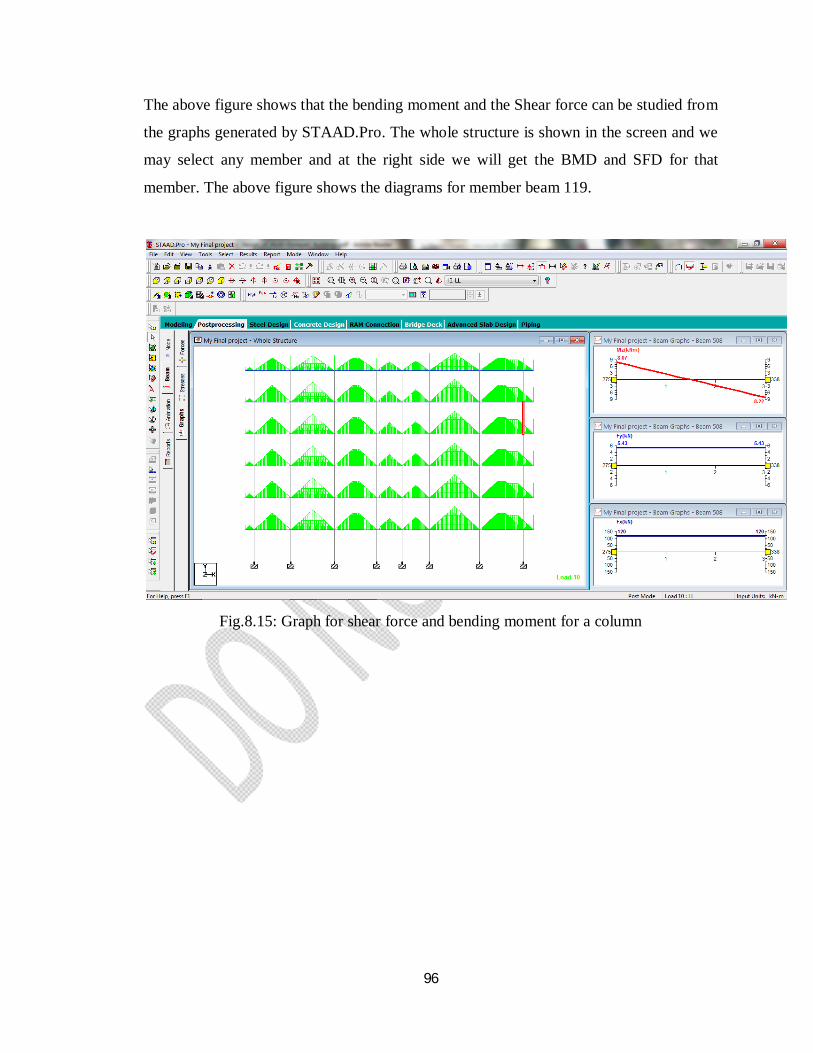
96
The above figure shows that the bending moment and the Shear force can be studied from
the graphs generated by STAAD.Pro. The whole structure is shown in the screen and we
may select any member and at the right side we will get the BMD and SFD for that
member. The above figure shows the diagrams for member beam 119.
Fig.8.15: Graph for shear force and bending moment for a column

97
CONCLUSION
98
CONCLUSION 1. This project is mainly concentrated with the analysis and design of multi-storied
residential building with all possible cases of the loadings using STAAD.Pro
Meeting the design challenges are described in conceptual way.
2. We may also check the deflection of various members under the given loading
combinations.
3. Further in case of rectification it is simple to change the values at the place where
error occurred and the obtained results are generated in the output.
4. Very less space is required for the storage of the data.
5. STAAD.Pro V8i an advanced software which provides us a fast, efficient, easy to use
and accurate platform for analyzing and designing structures.

99
REFERNCES
100
REFERNCES
IS: 875 (Part 1) – 1987 for Dead Loads, Indian Standard Code Of Practice for
Design Loads (Other Than Earthquake) For Buildings and Structures, Bureau of
Indian Standards, Manak Bhavan, 9 Bahadur Shah Zafar Marg, New Delhi
110002.
IS: 875 (Part 2) – 1987 for Imposed Loads, Indian Standard Code Of Practice
for Design Loads (Other Than Earthquake) For Buildings and Structures, Bureau
of Indian Standards, Manak Bhavan, 9 Bahadur Shah Zafar Marg, New Delhi
110002.
IS: 875 (Part 3) – 1987 for Wind Loads, Indian Standard Code Of Practice for
Design Loads (Other Than Earthquake) For Buildings And Structures, Bureau of
Indian Standards, Manak Bhavan, 9 Bahadur Shah Zafar Marg, New Delhi
110002.
IS: 875 (Part 5) – 1987 for Special Loads and Combinations, Indian Standard
Code Of Practice for Design Loads (Other Than Earthquake) For Buildings and
Structures, Bureau of Indian Standards, Manak Bhavan, 9 Bahadur Shah Zafar
Marg, New Delhi 110002.
IS 1893 (Part 1)-2002, Indian Standard Criteria for Earthquake Resistant Design
of Structures, (Part 1-General Provisions and Buildings), Bureau of Indian
Standards, Manak Bhavan, 9 Bahadur Shah Zafar Marg, New Delhi 110002.
IS 456-2000, Indian standard code of practice for plain and reinforced concrete
(fourth revision), Bureau of Indian Standards, New Delhi, July 2000.
SP: 16-1980, Design aids for reinforced concrete to IS: 456, Bureau of Indian
standards, New Delhi, 1980.
SP: 34-1987, Hand Book of Concrete Reinforcement and Detailing, Bureau of
Indian Standards, New Delhi, 1987.
Pilli, S.U. And Menon .D, “Reinforced concrete design”, Second edition, Tata
Mc Graw Hill Publishing Company Limited, New Delhi, 2003.
Jain, A.K. “Reinforced Concrete – Limit State Design”, Sixth edition, New Chand & Bros, Roorkee, 2002.