Embed Size (px)
Citation preview
· In Wenchuan Earthquake (M8.0, May 12, 2008),nearly1600 bridges suffered extensive damages
· To judge the failure mechanisms and bearing capacity of thebridge
BACKGROUND & PURPOSE
STUDY
·Surface faults
Observed Damage
·Structure failures
Comparison
Conclusions
·For small displacement
Pushover Analysis
·For support lost
·Span 1, 2: mainly surface fault
Failure Mechanisms
·Span 3, 4: mainly seismic load
·Rigid-frame arch RC bridge
Bridge Structure
·2×42.35+2×43.15m (assumed)
Fig.2 Flow of Study
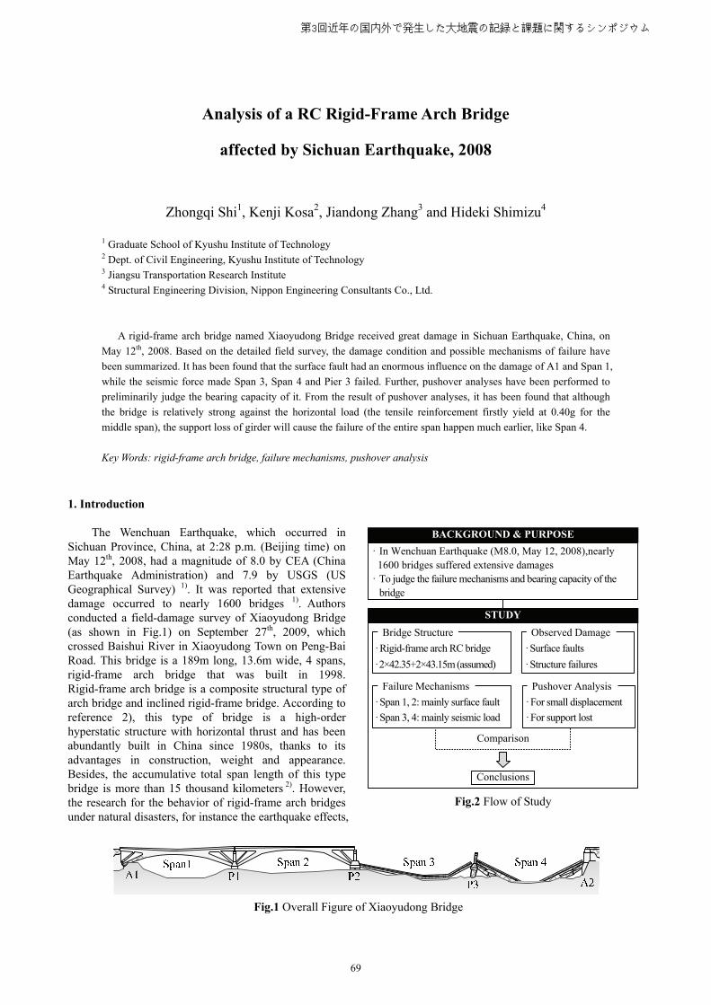
Fig.1 Overall Figure of Xiaoyudong Bridge
Analysis of a RC Rigid-Frame Arch Bridge
affected by Sichuan Earthquake, 2008
Zhongqi Shi1, Kenji Kosa2, Jiandong Zhang3 and Hideki Shimizu4
1 Graduate School of Kyushu Institute of Technology 2 Dept. of Civil Engineering, Kyushu Institute of Technology 3 Jiangsu Transportation Research Institute
4 Structural Engineering Division, Nippon Engineering Consultants Co., Ltd.
A rigid-frame arch bridge named Xiaoyudong Bridge received great damage in Sichuan Earthquake, China, on
May 12th, 2008. Based on the detailed field survey, the damage condition and possible mechanisms of failure have
been summarized. It has been found that the surface fault had an enormous influence on the damage of A1 and Span 1,
while the seismic force made Span 3, Span 4 and Pier 3 failed. Further, pushover analyses have been performed to
preliminarily judge the bearing capacity of it. From the result of pushover analyses, it has been found that although
the bridge is relatively strong against the horizontal load (the tensile reinforcement firstly yield at 0.40g for the
middle span), the support loss of girder will cause the failure of the entire span happen much earlier, like Span 4.
Key Words: rigid-frame arch bridge, failure mechanisms, pushover analysis
1. Introduction The Wenchuan Earthquake, which occurred in Sichuan Province, China, at 2:28 p.m. (Beijing time) on May 12th, 2008, had a magnitude of 8.0 by CEA (China Earthquake Administration) and 7.9 by USGS (US Geographical Survey) 1). It was reported that extensive damage occurred to nearly 1600 bridges 1). Authors conducted a field-damage survey of Xiaoyudong Bridge (as shown in Fig.1) on September 27th, 2009, which crossed Baishui River in Xiaoyudong Town on Peng-Bai Road. This bridge is a 189m long, 13.6m wide, 4 spans, rigid-frame arch bridge that was built in 1998. Rigid-frame arch bridge is a composite structural type of arch bridge and inclined rigid-frame bridge. According to reference 2), this type of bridge is a high-order hyperstatic structure with horizontal thrust and has been abundantly built in China since 1980s, thanks to its advantages in construction, weight and appearance. Besides, the accumulative total span length of this type bridge is more than 15 thousand kilometers 2). However, the research for the behavior of rigid-frame arch bridges under natural disasters, for instance the earthquake effects,
第3回近年の国内外で発生した大地震の記録と課題に関するシンポジウム
69
3750
900
1800
6450
21575
VIV
III
III
4 25
4 22
2 162 22
350
220
750
I
I
II
II
450
350
4 122 124 12
4 25
2 16
350
2 22220
750
720
3502 163 22
2 122 163 22
350
2 162 16
5 22
5 25
220
650
IV
V
IV-IV V-VIII-IIIII-III-I
40°
21°
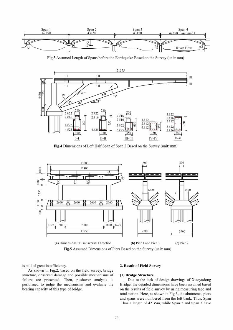
Fig.4 Dimensions of Left Half Span of Span 2 Based on the Survey (unit: mm)
700
1100
2750
1000
1000
13600
12400
220
130
550
2660 2660 2660
1625 1800 7000 1800
13850 2700 3900
1200
800
2400
1625
800
2660
A
B
(a) Dimensions in Transversal Direction (b) Pier 1 and Pier 3 (c) Pier 2
Fig.5 Assumed Dimensions of Piers Based on the Survey (unit: mm)
42350 43150 43150 42350(assumed)Span 1 Span 2 Span 3 Span 4
A1P1 P2 P3 A2River Flow
Fig.3 Assumed Length of Spans before the Earthquake Based on the Survey (unit: mm)
is still of great insufficiency. As shown in Fig.2, based on the field survey, bridge
structure, observed damage and possible mechanisms of failure are presented. Then, pushover analysis is performed to judge the mechanisms and evaluate the bearing capacity of this type of bridge.
2. Result of Field Survey (1) Bridge Structure Due to the lack of design drawings of Xiaoyudong Bridge, the detailed dimensions have been assumed based on the results of field survey by using measuring tape and total station. Here, as shown in Fig.3, the abutments, piers and spans were numbered from the left bank. Thus, Span 1 has a length of 42.35m, while Span 2 and Span 3 have
70
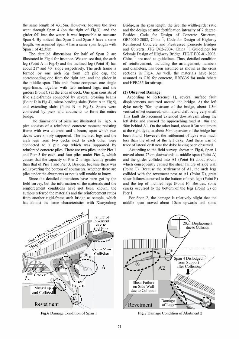
Fig.6 Damage Condition of Span 1
Shear Failure on Side Wall
due to Collision
20cm Displacement due to Collision
A2
RevetmentDamage of Legs
Span 4 Dislodged from Support after Collision
A
B
Fig.7 Damage Condition of Abutment 2
the same length of 43.15m. However, because the river went through Span 4 (on the right of Fig.3), and the girder fell into the water, it was impossible to measure Span 4. By noticed that Span 2 and Span 3 have a same length, we assumed Span 4 has a same span length with Span 1 of 42.35m.
The detailed dimensions for half of Span 2 are illustrated in Fig.4 for instance. We can see that, the arch leg (Point A in Fig.4) and the inclined leg (Point B) has about 21° and 40° slope respectively. The arch frame is formed by one arch leg from left pile cap, the corresponding one from the right cap, and the girder in the middle span. This arch frame composes one single rigid-frame, together with two inclined legs, and the girders (Point C) at the ends of deck. One span consists of five rigid-frames connected by several crossing beams (Point D in Fig.4), micro-bending slabs (Point A in Fig.5), and extending slabs (Point B in Fig.5). Spans were connected by piers and abutments to form the entire bridge.
The dimensions of piers are illustrated in Fig.5. A pier consists of a reinforced concrete moment resisting frame with two columns and a beam, upon which two decks were simply supported. The inclined legs and the arch legs from two decks next to each other were connected to a pile cap which was supported by reinforced concrete piles. There are two piles under Pier 1 and Pier 3 for each, and four piles under Pier 2, which causes that the capacity of Pier 2 is significantly greater than that of Pier 1 and Pier 3. Besides, because there was soil covering the bottom of abutments, whether there are piles under the abutments or not is still unable to know. Since the detailed dimensions have been got by the field survey, but the information of the materials and the reinforcement conditions have not been known, the authors referred the materials and the reinforcement ratios from another rigid-frame arch bridge as sample, which has almost the same characteristics with Xiaoyudong
Bridge, as the span length, the rise, the width-girder ratio and the design seismic fortification intensity of 7 degree. Besides, Code for Design of Concrete Structure, GB50010-2002, China 3), Code for Design of Highway Reinforced Concrete and Prestressed Concrete Bridges and Culverts, JTG D62-2004, China 4), Guidelines for Seismic Design of Highway Bridge, JTG/T B02-01-2008, China 5) are used as guidelines. Thus, detailed condition of reinforcement, including the arrangement, numbers and diameters, has been assumed as shown as the cross sections in Fig.4. As well, the materials have been assumed as C30 for concrete, HRB335 for main rebars and HPB235 for stirrups. (2) Observed Damage
According to Reference 1), several surface fault displacements occurred around the bridge. At the left dyke nearly 70m upstream of the bridge, about 1.5m vertical offset occurred, with lateral drift being very small. This fault displacement extended downstream along the left dyke and crossed the approaching road at 10m and 50m behind A1. On the other hand, about 0.3m settlement at the right dyke, at about 50m upstream of the bridge has been found. However, the settlement of dyke was much less than the offset of the left dyke. And there was no trace of lateral drift near the dyke having been observed.
According to the field survey, shown in Fig.6, Span 1 moved about 75cm downwards at middle span (Point A) and the girder collided into A1 (Point B) about 90cm, which consequently caused the shear failure of side wall (Point C). Because the settlement of A1, the arch legs collided with the revetment next to A1 (Point D), great shear failures occurred to the bottom of arch legs (Point E) and the top of inclined legs (Point F). Besides, some cracks occurred to the bottom of the legs (Point G) on Pier 1.
For Span 2, the damage is relatively slight that the middle span moved about 10cm upwards and some
71
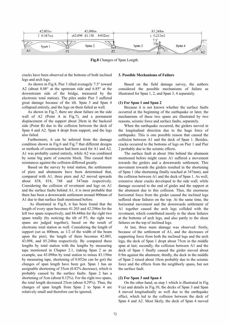
Fig.8 Changes of Span Length
cracks have been observed at the bottoms of both inclined legs and arch legs.
As shown in Fig.8, Pier 3 tilted averagely 7.5° toward A2 (about 8.08° at the upstream side and 6.85° at the downstream side of the bridge, measured by the electronic total station). The piles under Pier 3 suffered great damage because of the tilt. Span 3 and Span 4 collapsed entirely, and the legs on them failed as well.
As shown in Fig.7, there are shear failure on the side wall of A2 (Point A in Fig.7), and a permanent displacement of the support about 20cm in the backsoil side (Point B) due to the collision between the deck of Span 4 and A2. Span 4 dropt from support, and the legs also failed.
Furthermore, it can be inferred from the damage condition shown in Fig.6 and Fig.7 that different designs or methods of construction had been used for A1 and A2. A1 was probably casted entirely, while A2 was combined by some big parts of concrete block. This casued their resistances against the collision differred greatly.
Based on the survey by total station, the settlements of piers and abutments have been determined that, compared with A1, three piers and A2 moved upwards about 838, 818, 748 and 547mm respectively. Considering the collision of revetment and legs on A1 and the surface faults behind A1, it is most probable that there has been a downwards settlement around 800mm of A1 due to that surface fault mentioned before.
As illustrated in Fig.8, it has been found that the length of every span becomes 41.203 and 42.298m for the left two spans respectively, and 84.448m for the right two spans totally (by noticing the tilt of P3, the right two spans are judged together), based on the result of electronic total station as well. Considering the length of support (set as 400mm, as 1/2 of the width of the beam upon the pier), the length of them becomes 42.003, 43.098, and 85.248m respectively. By compared these lengths by total station with the lengths by measuring tape mentioned in Chapter 2.1, (taking Span 2 as an example, use 43.098m by total station to minus 43.150m by measuring tape, shortening of 0.052m can be got) the changes of span length have been got. Span 1 has an assignable shortening of 35cm (0.82% decrease), which is probably caused by the surface faults. Span 2 has a shortening of 5cm (about 0.12%). For the right two spans, the total length decreased 25cm (about 0.29%). Thus, the changes of span length from Span 2 to Span 4 are relatively small and therefore can be ignored.
3. Possible Mechanisms of Failure
Based on the field damage survey, the authors considered the possible mechanisms of failure as illustrated for Span 1, 2, and Span 3, 4 separately. (1) For Span 1 and Span 2
Because it is not known whether the surface faults occurred at the beginning of the earthquake or later, the mechanisms of these two spans are illustrated by two reasons, seismic force and surface faults, separately.
When the earthquake occurred, the girders moved in the longitudinal direction due to the huge force of earthquake. This is one possible reason that caused the collision between A1 and the deck of Span 1. Besides, cracks occurred to the bottoms of legs on Pier 1 and Pier 2 probably due to the seismic effects.
The surface fault at about 10m behind the abutment mentioned before might cause A1 suffered a movement towards the girders and a downwards settlement. This movement towards the girders resulted in the shortening of Span 1 (the shortening finally reached at 347mm), and the collision between A1 and the deck of Span 1. As well, extensive shear cracks developed in the side wall, while damage occurred to the end of girder and the support at the abutment due to this collision. Thus, the enormous horizontal force from the girder caused the inclined legs suffered shear failures on the top. At the same time, the horizontal movement and the downwards settlement of A1 together caused the arch legs collided with the revetment, which contributed mostly to the shear failures at the bottoms of arch legs, and also partly to the shear failures on the top of inclined legs.
At last, three main damage was observed: firstly, because of the settlement of A1, and the decreases of supporting force from both the inclined legs and the arch legs, the deck of Span 1 dropt about 75cm in the middle span at last; secondly, the collision between A1 and the deck of Span 1 finally caused the girder moved about 0.9m against the abutment; thirdly, the deck in the middle of Span 2 raised about 10cm probably due to the seismic force and the effects from the neighborly spans, but not the surface fault. (2) For Span 3 and Span 4
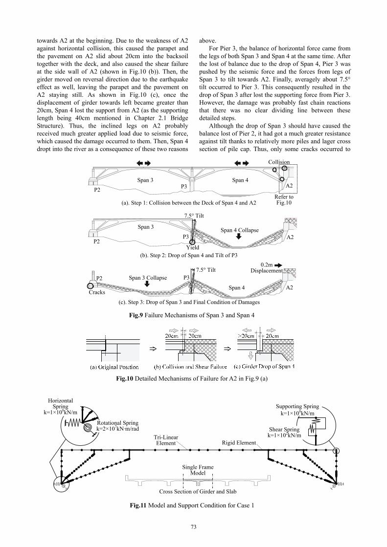
On the other hand, as step 1 which is illustrated in Fig. 9 (a) and details in Fig.10, the decks of Span 3 and Span 4 moved longitudinally as well due to the earthquake effect, which led to the collision between the deck of Span 4 and A2. Most likely, the deck of Span 4 moved
72
Collision
P2P3 A2
Span 3 Span 4
(a). Step 1: Collision between the Deck of Span 4 and A2Refer to Fig.10
7.5° Tilt
Span 4 Collapse
P2P3
Span 3
A2
Yield(b). Step 2: Drop of Span 4 and Tilt of P3
P3P2
Cracks
0.2m Displacement
Span 4
Span 3 Collapse
A2
7.5° Tilt
(c). Step 3: Drop of Span 3 and Final Condition of Damages
Fig.9 Failure Mechanisms of Span 3 and Span 4
Fig.10 Detailed Mechanisms of Failure for A2 in Fig.9 (a)
Rotational Springk=2×10⁷kN·m/rad
Supporting Springk=1×10⁸kN/m
Shear Springk=1×10²kN/m
Rigid ElementTri-Linear Element
Cross Section of Girder and Slab
Single Frame Model
Horizontal Spring
k=1×10⁸kN/m
Fig.11 Model and Support Condition for Case 1
towards A2 at the beginning. Due to the weakness of A2 against horizontal collision, this caused the parapet and the pavement on A2 slid about 20cm into the backsoil together with the deck, and also caused the shear failure at the side wall of A2 (shown in Fig.10 (b)). Then, the girder moved on reversal direction due to the earthquake effect as well, leaving the parapet and the pavement on A2 staying still. As shown in Fig.10 (c), once the displacement of girder towards left became greater than 20cm, Span 4 lost the support from A2 (as the supporting length being 40cm mentioned in Chapter 2.1 Bridge Structure). Thus, the inclined legs on A2 probably received much greater applied load due to seismic force, which caused the damage occurred to them. Then, Span 4 dropt into the river as a consequence of these two reasons
above. For Pier 3, the balance of horizontal force came from
the legs of both Span 3 and Span 4 at the same time. After the lost of balance due to the drop of Span 4, Pier 3 was pushed by the seismic force and the forces from legs of Span 3 to tilt towards A2. Finally, averagely about 7.5° tilt occurred to Pier 3. This consequently resulted in the drop of Span 3 after lost the supporting force from Pier 3. However, the damage was probably fast chain reactions that there was no clear dividing line between these detailed steps.
Although the drop of Span 3 should have caused the balance lost of Pier 2, it had got a much greater resistance against tilt thanks to relatively more piles and lager cross section of pile cap. Thus, only some cracks occurred to
73
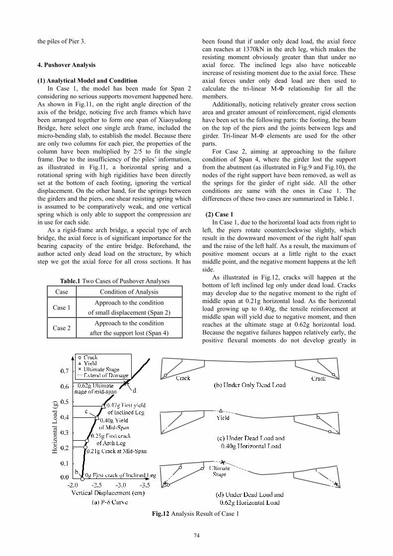
Table.1 Two Cases of Pushover Analyses
Case Condition of Analysis
Case 1 Approach to the condition
of small displacement (Span 2)
Case 2 Approach to the condition
after the support lost (Span 4)
Hor
izon
tal L
oad
(g)
Fig.12 Analysis Result of Case 1
the piles of Pier 3. 4. Pushover Analysis (1) Analytical Model and Condition
In Case 1, the model has been made for Span 2 considering no serious supports movement happened here. As shown in Fig.11, on the right angle direction of the axis of the bridge, noticing five arch frames which have been arranged together to form one span of Xiaoyudong Bridge, here select one single arch frame, included the micro-bending slab, to establish the model. Because there are only two columns for each pier, the properties of the column have been multiplied by 2/5 to fit the single frame. Due to the insufficiency of the piles’ information, as illustrated in Fig.11, a horizontal spring and a rotational spring with high rigidities have been directly set at the bottom of each footing, ignoring the vertical displacement. On the other hand, for the springs between the girders and the piers, one shear resisting spring which is assumed to be comparatively weak, and one vertical spring which is only able to support the compression are in use for each side.
As a rigid-frame arch bridge, a special type of arch bridge, the axial force is of significant importance for the bearing capacity of the entire bridge. Beforehand, the author acted only dead load on the structure, by which step we got the axial force for all cross sections. It has
been found that if under only dead load, the axial force can reaches at 1370kN in the arch leg, which makes the resisting moment obviously greater than that under no axial force. The inclined legs also have noticeable increase of resisting moment due to the axial force. These axial forces under only dead load are then used to calculate the tri-linear M-Φ relationship for all the members.
Additionally, noticing relatively greater cross section area and greater amount of reinforcement, rigid elements have been set to the following parts: the footing, the beam on the top of the piers and the joints between legs and girder. Tri-linear M-Φ elements are used for the other parts.
For Case 2, aiming at approaching to the failure condition of Span 4, where the girder lost the support from the abutment (as illustrated in Fig.9 and Fig.10), the nodes of the right support have been removed, as well as the springs for the girder of right side. All the other conditions are same with the ones in Case 1. The differences of these two cases are summarized in Table.1.
(2) Case 1
In Case 1, due to the horizontal load acts from right to left, the piers rotate counterclockwise slightly, which result in the downward movement of the right half span and the raise of the left half. As a result, the maximum of positive moment occurs at a little right to the exact middle point, and the negative moment happens at the left side.
As illustrated in Fig.12, cracks will happen at the bottom of left inclined leg only under dead load. Cracks may develop due to the negative moment to the right of middle span at 0.21g horizontal load. As the horizontal load growing up to 0.40g, the tensile reinforcement at middle span will yield due to negative moment, and then reaches at the ultimate stage at 0.62g horizontal load. Because the negative failures happen relatively early, the positive flexural moments do not develop greatly in
74
10cm Raise at Middle Span
Possible Failure By Negative Moment
P2
P1
Cracks of Legs
Cracks of Legs
Possible Failures of Legs
Possible Failures of Legs
Pushover Load in Analysis
Results of AnalysisActual Failures
Fig.13 Comparison between Results of Case 1 and Actual Failures for Span 2
elements at middle span. For the inclined legs, the first yield of tensile reinforcement occurs to the left bottom at 0.47g horizontal load. The same point will reach at the ultimate stage soon. Then the yield of tensile reinforcement and the ultimate stage will happen to the right bottom of the inclined leg after the horizontal load becomes greater than 0.53g. For the arch legs, the damage will happen to the left bottom at first among all parts: cracks occur at 0.29g, yield of reinforcement at 0.93g, and soon the ultimate stage. Under 0.62g horizontal load, when is the ultimate stage of middle span, the deflection about 3.1cm happens to the middle span.
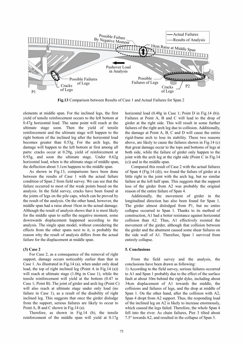
As shown in Fig.13, comparisons have been done between the results of Case 1 with the actual failure condition of Span 2 from field survey. We can see that the failure occurred to most of the weak points based on the analysis. In the field survey, cracks have been found at the joints of legs on the pile caps, which can be proved by the result of the analysis. On the other hand, however, the middle span had a raise about 10cm in the actual damage. Although the result of analysis shows that it is most likely for the middle span to suffer the negative moment, some downwards displacement happened according to the analysis. The single span model, without considering the effects from the other spans next to it, is probably the reason why the result of analysis differs from the actual failure for the displacement at middle span.
(3) Case 2
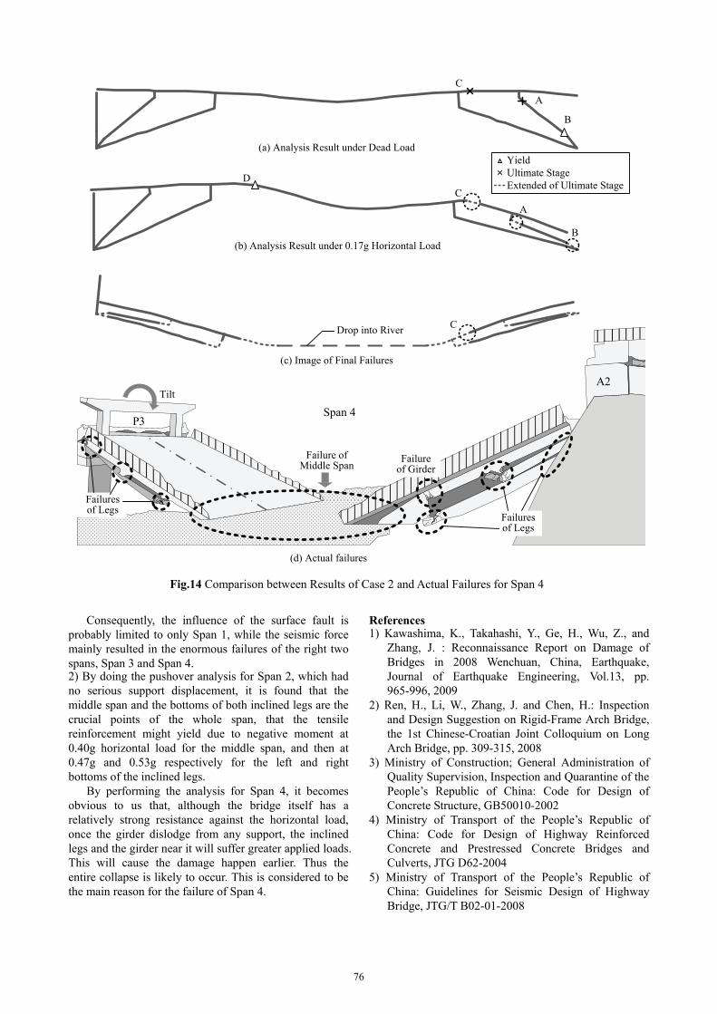
For Case 2, as a consequence of the removal of right support, damage occurs noticeably earlier than that in Case 1. As illustrated in Fig.14 (a), when under only dead load, the top of right inclined leg (Point A in Fig.14 (a)) will reach at ultimate stage (1.06g in Case 1), while the tensile reinforcement will yield at the bottom (0.47 in Case 1; Point B). The joint of girder and arch leg (Point C) will also reach at ultimate stage under only load (no failure in Case 1), as a result of the disability of right inclined leg. This suggests that once the girder dislodge from the support, serious failures are likely to occur to Point A, B and C shown in Fig.14 (a).
Therefore, as shown in Fig.14 (b), the tensile reinforcement of the middle span will yield at 0.17g
horizontal load (0.40g in Case 1; Point D in Fig.14 (b)). Failures at Point A, B and C will lead to the drop of girder at the right side. This will result in some further failures of the right arch leg due to collision. Additionally, the damage at Point A, B, C and D will cause the entire rigid-frame arch to lose its stability. These two reasons above, are likely to cause the failures shown in Fig.14 (c) that great damage occur to the tops and bottoms of legs at both side, while the failure of girder only happen to the joint with the arch leg at the right side (Point C in Fig.14 (c)) and in the middle span.
Compared this result of Case 2 with the actual failures of Span 4 (Fig.14 (d)), we found the failure of girder at a little right to the joint with the arch leg, but no similar failure at the left half span. This suggests that the support loss of the girder from A2 was probably the original reason of the entire failure of Span 4.
Additionally, the movement of girder in the longitudinal direction has also been found for Span 1. The girder almost dislodged from P1, but no entire collapse occurred to Span 1. Thanks to its method of construction, A1 had a better resistance against horizontal collision than A2. Thus, A1 effectively resisted the movement of the girder, although that collision between the girder and the abutment caused some shear failures on the side wall of A1. Therefore, Span 1 survived from entirely collapse. 5. Conclusions
From the field survey and the analysis, the conclusions have been drawn as following: 1) According to the field survey, serious failures occurred to A1 and Span 1 probably due to the effect of the surface fault at about 10m behind the right dyke, including about 34cm displacement of A1 towards the middle, the collisions and failures of legs, and the drop at middle of Span 1. On the other hand, after the collision with A2, Span 4 dropt from A2 support. Thus, the responding load of the inclined leg on A2 is likely to increase enormously, which caused the legs failed. Therefore, the whole Span 4 fell into the river. As chain failures, Pier 3 tilted about 7.5° towards A2, and resulted in the collapse of Span 3.
75
Tilt
P3
Failures of Legs
Failures of Legs
Failure of Middle Span
Failure of Girder
Span 4
A2
(d) Actual failures
(b) Analysis Result under 0.17g Horizontal Load
D
A
B
C
A
B
C
(a) Analysis Result under Dead Load YieldUltimate StageExtended of Ultimate Stage
Drop into River
(c) Image of Final Failures
C
Fig.14 Comparison between Results of Case 2 and Actual Failures for Span 4
Consequently, the influence of the surface fault is probably limited to only Span 1, while the seismic force mainly resulted in the enormous failures of the right two spans, Span 3 and Span 4. 2) By doing the pushover analysis for Span 2, which had no serious support displacement, it is found that the middle span and the bottoms of both inclined legs are the crucial points of the whole span, that the tensile reinforcement might yield due to negative moment at 0.40g horizontal load for the middle span, and then at 0.47g and 0.53g respectively for the left and right bottoms of the inclined legs. By performing the analysis for Span 4, it becomes obvious to us that, although the bridge itself has a relatively strong resistance against the horizontal load, once the girder dislodge from any support, the inclined legs and the girder near it will suffer greater applied loads. This will cause the damage happen earlier. Thus the entire collapse is likely to occur. This is considered to be the main reason for the failure of Span 4.
References 1) Kawashima, K., Takahashi, Y., Ge, H., Wu, Z., and
Zhang, J. : Reconnaissance Report on Damage of Bridges in 2008 Wenchuan, China, Earthquake, Journal of Earthquake Engineering, Vol.13, pp. 965-996, 2009
2) Ren, H., Li, W., Zhang, J. and Chen, H.: Inspection and Design Suggestion on Rigid-Frame Arch Bridge, the 1st Chinese-Croatian Joint Colloquium on Long Arch Bridge, pp. 309-315, 2008
3) Ministry of Construction; General Administration of Quality Supervision, Inspection and Quarantine of the People’s Republic of China: Code for Design of Concrete Structure, GB50010-2002
4) Ministry of Transport of the People’s Republic of China: Code for Design of Highway Reinforced Concrete and Prestressed Concrete Bridges and Culverts, JTG D62-2004
5) Ministry of Transport of the People’s Republic of China: Guidelines for Seismic Design of Highway Bridge, JTG/T B02-01-2008
76