Embed Size (px)
Citation preview
Technical Report, IDE0709, January 2007
ANALYSIS OF MULTIMEDIANETWORKS FOR AUTOMOTIVE
APPLICATIONS
Master’s Thesis in Electrical Engineering
Kajetan Feichtenschlager, Petr Knopp
School of Information Science, Computer and Electrical Engineering, IDE
Halmstad University
Analysis of Multimedia Networks forAutomotive Applications
Master’s thesis in Electrical Engineering
School of Information Science, Computer and Electrical EngineeringHalmstad University
Box 823, S-301 18 Halmstad, Sweden
January 2007
Abstract
Automotive manufacturers face interesting challenges as electronic devices are becomingessential in modern vehicles. Therefore new approaches and strategies are to be adoptedin order to tackle the coming challenges. One of the most rapidly growing domains isinfotainment and telematics, where applications require a large amount of data to betransmitted on-board and also exchanged with the external world. The in-vehicle com-munication networks for infotainment systems must consequently be devised consideringthe need for transporting the considerable amount of data of multimedia applications aswell as features particular to this area.
This thesis is intended to analyze possible implementations of multimedia networks forheavy transport vehicles, in relation to various aspects and features in this area. Thethesis presents an analysis of different protocols and technologies used in automotive mul-timedia networks. Furthermore, characteristic requirements for automotive electronicssystems and especially for automotive multimedia networks are investigated in detail.Based on these requirements different multimedia networks are proposed and studied,making a comparison between them with regard to a number of criteria.
A broad approach during the investigation of the multimedia protocols is chosen in orderto enlarge the area of used technology and to bring new technologies and possibilities forthe truck industry. The observations and the experiences from the car industry are usedin the truck domain, where the specifics of the truck industry are taken into account.The comparison gives an insight into the particulars of the proposed solutions from sev-eral viewpoints so that a suitable multimedia network can be selected based on differentcriteria.
i

ANALYSIS OF MULTIMEDIA NETWORKS FOR AUTOMOTIVE APPLICATIONS
ii

Acknowledgement
This thesis results from close cooperation with Volvo 3P. Therefore we would like tothank our supervisor in Volvo 3P Alejandro Cortes for providing us with the valuableinformations and pleasant environment in the premises of Volvo 3P. Our thanks alsobelongs to our supervisor in Halmstad.
iii

ANALYSIS OF MULTIMEDIA NETWORKS FOR AUTOMOTIVE APPLICATIONS
iv
Acronyms
ACK/NAK Acknowledge/No Acknowledge: Indicates that a message was orwas not received correctly.
BER Bit Error Rate: is the ratio between the number of bits whichwere transmitted incorrectly and the total amount of bits trans-mitted.
CAN Controller Area Network: Most common field bus to connect theECUs in todays vehicles
CRC Cyclic Redundancy Check: Is an algorithm to detect data trans-mission errors
CCP Consumer Convenience PortDVB-T Digital Video Broadcasting Terrestrial: Standard for digital TVd2B Domestic Digital Bus: An early multimedia network for vehicles
based on an optical physical layerDTCP Digital Transmission Content ProtectionEBS Electronic Brake SystemECU Electronic Control Unit: A microprocessor which controls cer-
tain functions in a vehicleGPS Global Positioning SystemHMI Human Machine InterfaceLED Light Emitting DiodeLIN Local Interconnect Network: A low-cost low-speed in-vehicle net-
work, used for sensors and actuatorsMSC Message Sequence ChartOEM Original Equipment ManufacturerPCM Pulse Code ModulationPCS or HCS Polymer/Hard Clad SilicaPLL Phase-locked LoopPOF Plastic Optical FiberRDS Radio Data SystemRGB An color encoding system, where R, G and B represent the value
of the red, the green and the blue part of a pixelRTAI Linux Real-Time LinuxS/PDIF Sony Philips Digital Interface FormatVCSEL Vertical Cavity Surface Emitting LaserYUV An color encoding system, where Y represents the brightness, U
and V contain the color information
v

ANALYSIS OF MULTIMEDIA NETWORKS FOR AUTOMOTIVE APPLICATIONS
vi
CONTENTS
Contents
Abstract i
Acknowledgement iii
Acronyms v
1 Introduction and Related Projects 11.1 Introduction . . . . . . . . . . . . . . . . . . . . . . . . . . . . . . . . . . . 31.2 Background - Automotive Embedded Systems . . . . . . . . . . . . . . . . 41.3 Telematic and Infotainment Systems . . . . . . . . . . . . . . . . . . . . . 4
1.3.1 Safety and Security . . . . . . . . . . . . . . . . . . . . . . . . . . . 41.3.2 Remote Vehicle Diagnostics . . . . . . . . . . . . . . . . . . . . . . 51.3.3 In-Vehicle Telephony Systems . . . . . . . . . . . . . . . . . . . . . 51.3.4 Navigation and Fleet Management . . . . . . . . . . . . . . . . . . 51.3.5 Audio Video Systems . . . . . . . . . . . . . . . . . . . . . . . . . . 61.3.6 Connectivity . . . . . . . . . . . . . . . . . . . . . . . . . . . . . . . 6
1.4 Related Projects . . . . . . . . . . . . . . . . . . . . . . . . . . . . . . . . 61.4.1 Prototype of IDB-1394 Network . . . . . . . . . . . . . . . . . . . . 61.4.2 SCOOT-R . . . . . . . . . . . . . . . . . . . . . . . . . . . . . . . . 71.4.3 Ad-hoc Network . . . . . . . . . . . . . . . . . . . . . . . . . . . . . 81.4.4 Video Transfer over WLAN . . . . . . . . . . . . . . . . . . . . . . 91.4.5 MOST Networks in the Car Industry . . . . . . . . . . . . . . . . . 9
2 Automotive Networks and Protocols 112.1 MOST . . . . . . . . . . . . . . . . . . . . . . . . . . . . . . . . . . . . . . 13
2.1.1 Application Section . . . . . . . . . . . . . . . . . . . . . . . . . . . 142.1.2 Network Section . . . . . . . . . . . . . . . . . . . . . . . . . . . . . 162.1.3 Physical Section . . . . . . . . . . . . . . . . . . . . . . . . . . . . . 20
2.2 IDB-1394 . . . . . . . . . . . . . . . . . . . . . . . . . . . . . . . . . . . . 232.2.1 IDB-1394 Specification . . . . . . . . . . . . . . . . . . . . . . . . . 232.2.2 Topology Configuration . . . . . . . . . . . . . . . . . . . . . . . . 242.2.3 Normal Arbitration . . . . . . . . . . . . . . . . . . . . . . . . . . . 242.2.4 Performance . . . . . . . . . . . . . . . . . . . . . . . . . . . . . . . 252.2.5 VersaPHY . . . . . . . . . . . . . . . . . . . . . . . . . . . . . . . . 25
2.3 SAE J1939 . . . . . . . . . . . . . . . . . . . . . . . . . . . . . . . . . . . . 252.3.1 Physical Layer . . . . . . . . . . . . . . . . . . . . . . . . . . . . . . 252.3.2 Data Link Layer . . . . . . . . . . . . . . . . . . . . . . . . . . . . 262.3.3 Network Layer . . . . . . . . . . . . . . . . . . . . . . . . . . . . . 262.3.4 Vehicle Application Layer . . . . . . . . . . . . . . . . . . . . . . . 272.3.5 Network Management . . . . . . . . . . . . . . . . . . . . . . . . . 27
2.4 APIX Link . . . . . . . . . . . . . . . . . . . . . . . . . . . . . . . . . . . . 272.5 Physical Layer . . . . . . . . . . . . . . . . . . . . . . . . . . . . . . . . . . 28
vii
ANALYSIS OF MULTIMEDIA NETWORKS FOR AUTOMOTIVE APPLICATIONS
2.5.1 Electrical Medium . . . . . . . . . . . . . . . . . . . . . . . . . . . 282.5.2 Optical Medium . . . . . . . . . . . . . . . . . . . . . . . . . . . . . 282.5.3 Cable Comparison . . . . . . . . . . . . . . . . . . . . . . . . . . . 29
3 Performance Requirements 313.1 Performance Requirements and Characteristics of Automotive Multimedia
Systems . . . . . . . . . . . . . . . . . . . . . . . . . . . . . . . . . . . . . 333.1.1 Requirements of automotive electronics . . . . . . . . . . . . . . . . 33
3.1.1.1 Cost . . . . . . . . . . . . . . . . . . . . . . . . . . . . . . 333.1.1.2 Dependability . . . . . . . . . . . . . . . . . . . . . . . . . 343.1.1.3 Flexibility . . . . . . . . . . . . . . . . . . . . . . . . . . . 343.1.1.4 Standardization . . . . . . . . . . . . . . . . . . . . . . . . 343.1.1.5 Compatibility . . . . . . . . . . . . . . . . . . . . . . . . . 353.1.1.6 Scalability . . . . . . . . . . . . . . . . . . . . . . . . . . . 353.1.1.7 Variability . . . . . . . . . . . . . . . . . . . . . . . . . . . 353.1.1.8 Responsibility . . . . . . . . . . . . . . . . . . . . . . . . . 35
3.1.2 Requirements of Telematic and Infotainment systems . . . . . . . . 353.1.2.1 Bandwidth . . . . . . . . . . . . . . . . . . . . . . . . . . 363.1.2.2 QoS . . . . . . . . . . . . . . . . . . . . . . . . . . . . . . 363.1.2.3 Delay . . . . . . . . . . . . . . . . . . . . . . . . . . . . . 363.1.2.4 Branding . . . . . . . . . . . . . . . . . . . . . . . . . . . 363.1.2.5 Power Supply . . . . . . . . . . . . . . . . . . . . . . . . . 363.1.2.6 Packaging . . . . . . . . . . . . . . . . . . . . . . . . . . . 363.1.2.7 Software strategy . . . . . . . . . . . . . . . . . . . . . . . 373.1.2.8 Feature expansion possibility . . . . . . . . . . . . . . . . 373.1.2.9 Technology risks . . . . . . . . . . . . . . . . . . . . . . . 373.1.2.10 Specific Aspects . . . . . . . . . . . . . . . . . . . . . . . 37
3.1.3 Relations between Aspects . . . . . . . . . . . . . . . . . . . . . . . 38
4 Evaluation of different topologies 394.1 CAN-based Networks . . . . . . . . . . . . . . . . . . . . . . . . . . . . . . 41
4.1.1 Typical Multimedia Topology for Trucks . . . . . . . . . . . . . . . 414.1.2 Description . . . . . . . . . . . . . . . . . . . . . . . . . . . . . . . 414.1.3 Communication . . . . . . . . . . . . . . . . . . . . . . . . . . . . . 414.1.4 Aspects . . . . . . . . . . . . . . . . . . . . . . . . . . . . . . . . . 424.1.5 Summary . . . . . . . . . . . . . . . . . . . . . . . . . . . . . . . . 44
4.2 MOST50 Network . . . . . . . . . . . . . . . . . . . . . . . . . . . . . . . . 444.2.1 Description . . . . . . . . . . . . . . . . . . . . . . . . . . . . . . . 444.2.2 Related projects . . . . . . . . . . . . . . . . . . . . . . . . . . . . . 454.2.3 Communication . . . . . . . . . . . . . . . . . . . . . . . . . . . . . 464.2.4 Aspects . . . . . . . . . . . . . . . . . . . . . . . . . . . . . . . . . 474.2.5 Summary . . . . . . . . . . . . . . . . . . . . . . . . . . . . . . . . 49
4.3 Network based on IDB-1394 . . . . . . . . . . . . . . . . . . . . . . . . . . 494.3.1 Description . . . . . . . . . . . . . . . . . . . . . . . . . . . . . . . 494.3.2 Aspects . . . . . . . . . . . . . . . . . . . . . . . . . . . . . . . . . 504.3.3 Summary . . . . . . . . . . . . . . . . . . . . . . . . . . . . . . . . 51
4.4 Network using the APIX link . . . . . . . . . . . . . . . . . . . . . . . . . 51
viii
CONTENTS
4.4.1 Description . . . . . . . . . . . . . . . . . . . . . . . . . . . . . . . 514.4.2 Communication . . . . . . . . . . . . . . . . . . . . . . . . . . . . . 524.4.3 Aspects . . . . . . . . . . . . . . . . . . . . . . . . . . . . . . . . . 544.4.4 Summary . . . . . . . . . . . . . . . . . . . . . . . . . . . . . . . . 55
4.5 Comparison of the Proposed Networks . . . . . . . . . . . . . . . . . . . . 554.6 Conclusions . . . . . . . . . . . . . . . . . . . . . . . . . . . . . . . . . . . 56
ix

ANALYSIS OF MULTIMEDIA NETWORKS FOR AUTOMOTIVE APPLICATIONS
x
LIST OF TABLES
List of Tables
1 MOST network matching the OSI Model . . . . . . . . . . . . . . . . . . . . 132 IDB-1394 network matching the OSI Model . . . . . . . . . . . . . . . . . . 243 SAE J1939 network matching the OSI Model . . . . . . . . . . . . . . . . . 264 Comparison of cables used in the automotive networks[27] . . . . . . . . . . 30
5 Aspects of the particular solutions compared to each other . . . . . . . . . . 55
xi

ANALYSIS OF MULTIMEDIA NETWORKS FOR AUTOMOTIVE APPLICATIONS
xii
LIST OF FIGURES
List of Figures
1 Virtual and real communication between two devices [9] . . . . . . . . . . . 152 MOST Network Service [9] . . . . . . . . . . . . . . . . . . . . . . . . . . . . 173 Structure of MOST25 Data Frame [9] . . . . . . . . . . . . . . . . . . . . . . 184 Structure of MOST50 Data Frame . . . . . . . . . . . . . . . . . . . . . . . 185 Development of the Intelligent NIC from Network Interface Controller [22] . 22
6 Performance requirements . . . . . . . . . . . . . . . . . . . . . . . . . . . . 33
7 Insufficiency of the CAN bus as a multimedia network . . . . . . . . . . . . 428 CAN-based solution . . . . . . . . . . . . . . . . . . . . . . . . . . . . . . . 439 MOST50 Network . . . . . . . . . . . . . . . . . . . . . . . . . . . . . . . . 4510 MOST Example . . . . . . . . . . . . . . . . . . . . . . . . . . . . . . . . . 4611 Topology of the proposed IDB-1394 network . . . . . . . . . . . . . . . . . . 5012 Topology based on the APIX link . . . . . . . . . . . . . . . . . . . . . . . . 5313 Adaptation of MSCs for Automotive Multimedia Networks: a) General in-
stance for user interaction b) MSCs message c) Timer (set and timeout) . . 6314 An example from section 4.2.3 described by MSCs . . . . . . . . . . . . . . 64
xiii

ANALYSIS OF MULTIMEDIA NETWORKS FOR AUTOMOTIVE APPLICATIONS
xiv

CHAPTER 1. INTRODUCTION AND RELATED PROJECTS
1 Introduction and Related Projects
1

ANALYSIS OF MULTIMEDIA NETWORKS FOR AUTOMOTIVE APPLICATIONS
2
CHAPTER 1. INTRODUCTION AND RELATED PROJECTS
Introduction and Related Projects
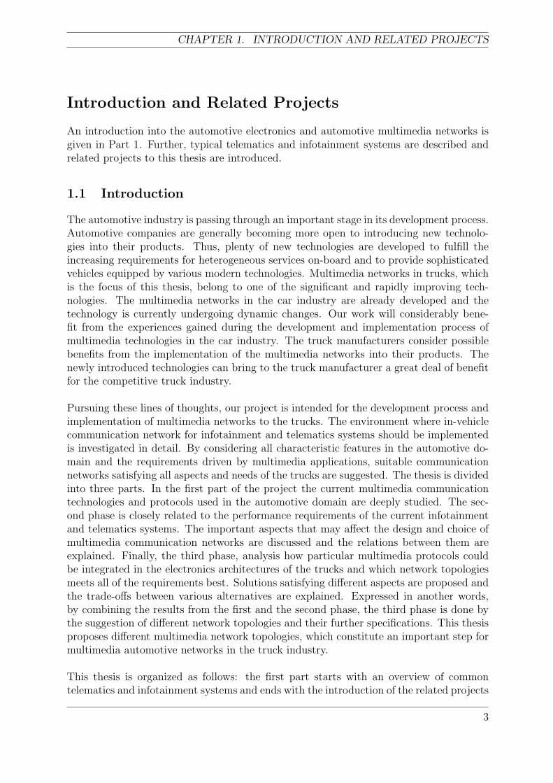
An introduction into the automotive electronics and automotive multimedia networks isgiven in Part 1. Further, typical telematics and infotainment systems are described andrelated projects to this thesis are introduced.
1.1 Introduction
The automotive industry is passing through an important stage in its development process.Automotive companies are generally becoming more open to introducing new technolo-gies into their products. Thus, plenty of new technologies are developed to fulfill theincreasing requirements for heterogeneous services on-board and to provide sophisticatedvehicles equipped by various modern technologies. Multimedia networks in trucks, whichis the focus of this thesis, belong to one of the significant and rapidly improving tech-nologies. The multimedia networks in the car industry are already developed and thetechnology is currently undergoing dynamic changes. Our work will considerably bene-fit from the experiences gained during the development and implementation process ofmultimedia technologies in the car industry. The truck manufacturers consider possiblebenefits from the implementation of the multimedia networks into their products. Thenewly introduced technologies can bring to the truck manufacturer a great deal of benefitfor the competitive truck industry.
Pursuing these lines of thoughts, our project is intended for the development process andimplementation of multimedia networks to the trucks. The environment where in-vehiclecommunication network for infotainment and telematics systems should be implementedis investigated in detail. By considering all characteristic features in the automotive do-main and the requirements driven by multimedia applications, suitable communicationnetworks satisfying all aspects and needs of the trucks are suggested. The thesis is dividedinto three parts. In the first part of the project the current multimedia communicationtechnologies and protocols used in the automotive domain are deeply studied. The sec-ond phase is closely related to the performance requirements of the current infotainmentand telematics systems. The important aspects that may affect the design and choice ofmultimedia communication networks are discussed and the relations between them areexplained. Finally, the third phase, analysis how particular multimedia protocols couldbe integrated in the electronics architectures of the trucks and which network topologiesmeets all of the requirements best. Solutions satisfying different aspects are proposed andthe trade-offs between various alternatives are explained. Expressed in another words,by combining the results from the first and the second phase, the third phase is done bythe suggestion of different network topologies and their further specifications. This thesisproposes different multimedia network topologies, which constitute an important step formultimedia automotive networks in the truck industry.
This thesis is organized as follows: the first part starts with an overview of commontelematics and infotainment systems and ends with the introduction of the related projects
3
ANALYSIS OF MULTIMEDIA NETWORKS FOR AUTOMOTIVE APPLICATIONS
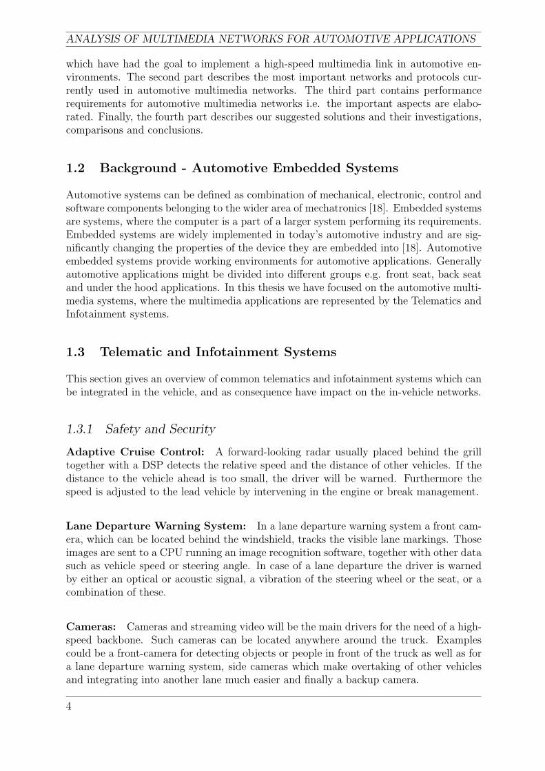
which have had the goal to implement a high-speed multimedia link in automotive en-vironments. The second part describes the most important networks and protocols cur-rently used in automotive multimedia networks. The third part contains performancerequirements for automotive multimedia networks i.e. the important aspects are elabo-rated. Finally, the fourth part describes our suggested solutions and their investigations,comparisons and conclusions.
1.2 Background - Automotive Embedded Systems
Automotive systems can be defined as combination of mechanical, electronic, control andsoftware components belonging to the wider area of mechatronics [18]. Embedded systemsare systems, where the computer is a part of a larger system performing its requirements.Embedded systems are widely implemented in today’s automotive industry and are sig-nificantly changing the properties of the device they are embedded into [18]. Automotiveembedded systems provide working environments for automotive applications. Generallyautomotive applications might be divided into different groups e.g. front seat, back seatand under the hood applications. In this thesis we have focused on the automotive multi-media systems, where the multimedia applications are represented by the Telematics andInfotainment systems.
1.3 Telematic and Infotainment Systems
This section gives an overview of common telematics and infotainment systems which canbe integrated in the vehicle, and as consequence have impact on the in-vehicle networks.
1.3.1 Safety and Security
Adaptive Cruise Control: A forward-looking radar usually placed behind the grilltogether with a DSP detects the relative speed and the distance of other vehicles. If thedistance to the vehicle ahead is too small, the driver will be warned. Furthermore thespeed is adjusted to the lead vehicle by intervening in the engine or break management.
Lane Departure Warning System: In a lane departure warning system a front cam-era, which can be located behind the windshield, tracks the visible lane markings. Thoseimages are sent to a CPU running an image recognition software, together with other datasuch as vehicle speed or steering angle. In case of a lane departure the driver is warnedby either an optical or acoustic signal, a vibration of the steering wheel or the seat, or acombination of these.
Cameras: Cameras and streaming video will be the main drivers for the need of a high-speed backbone. Such cameras can be located anywhere around the truck. Examplescould be a front-camera for detecting objects or people in front of the truck as well as fora lane departure warning system, side cameras which make overtaking of other vehiclesand integrating into another lane much easier and finally a backup camera.
4
CHAPTER 1. INTRODUCTION AND RELATED PROJECTS
1.3.2 Remote Vehicle Diagnostics
Remote vehicle diagnostics provides high potential of reducing costs. Some importantapplications are given below.
Breakdown Assistance: All new vehicles in Europe must be equipped with an auto-matic emergency call system called eCall by the year 2009 [11]. The eCall system willforward the exact location of the vehicle in the case of a crash to an emergency serviceusing the location-enhanced single European Emergency number (E-112) [11]. This callcan be initiated automatically or manually. Therefore the vehicles have to be equippedwith a GPS receiver and at least a GSM link.
Warranty Analysis: Error codes can be forwarded wirelessly to identify warrantytrends. Furthermore the fault identification time as well as the ”no fault found” compo-nents can be reduced. The latter is the case when the driver observes an unusual behaviorof the vehicle, but it can not be reproduced again at a service point. Costs can be reduced,as the production of potentially faulty vehicles will not be continued. The transmission ofvehicle running data can help the vehicle manufacturer to improve future vehicle design.As a GPS receiver and a GSM transmitter will be compulsory due to the eCall system,there will be no need for additional hardware in the vehicle.
Remote Software Download: The possibility to automatically download patches tofix ECU based errors brings the advantage of cost savings on recalls. Apparently thesecurity question has not been answered satisfactorily at the moment.
1.3.3 In-Vehicle Telephony Systems
An important technology for this purpose is Bluetooth. As the major European carmanufacturers already provide Bluetooth at least as an upgrade option, it is just a questionof time, when it will be implemented into truck networks. The Bluetooth link can be usedto realize hands free telephony as well as to enable the mobile’s GSM transmitter to sendtelematics data. The problem is still that it results in prohibitive cost and that not allmobile phones are supported due to the lack of profiles. However [20] claims that assoon as the number of Bluetooth-enabled phones will exceeds 50 % the cost factor canbe ignored. The next approach is to have a fully integrated GSM phone as a module inthe network and to use the HMI and audio system to substantiate the GSM functions.Finally an interface between GSM phone and automotive network can be used to send anaudio (data) signal to the automotive network and to charge the mobile unit.
1.3.4 Navigation and Fleet Management
Satellite navigation system GPS have become a standardized navigation technology forautomotive industry. The navigation unit can be a standalone device with its own displayor an integrated device into the multimedia subnet. The integrated version can be furtherdivided according to the software strategy into distributed or complex navigation units. Adistributed navigation device sends over the network only the data necessary to discoverits position, where the software part located in the head unit will calculate the position
5
ANALYSIS OF MULTIMEDIA NETWORKS FOR AUTOMOTIVE APPLICATIONS
and create the video signal. A complex navigation unit on the other hand calculates andcreates the video navigation signal and sends the compressed signal over the network.The fleet management systems control the vehicle position and behavior. For our purposethe fleet management system can utilize audio, phone, navigation, and telematics unitsto provide various services to the company and driver.
1.3.5 Audio Video Systems
Audio and video systems are the main drivers in the multimedia networks. Typically usedaudio and video devices in the multimedia networks are highlighted in this section.
Audio Devices: Audio devices can be implemented as a complex or standalone deviceand may consist of the following parts:
• Amplifier - analog amplification of the incoming signal
• Radio Tuner - supporting an analog or digital broadcasting with various additionalfunctions e.g. RDS
• CD player
Video Devices: Video devices are represented by a DVD player (DVB receiver) withconnected entertainment display. The video switch is engaged as a switch for the videosignals coming from different devices (e.g. a navigation unit or front-camera).
1.3.6 Connectivity
Gateway: The need for cooperation with other networks is satisfied by the gateways,where various items of information from the vehicle can be transferred to the differentsubnets. This data can be used for e.g. sending a digital odometer data to the company.
Connectivity Box: Connectivity box contains various interfaces to connect differentdevices. Further specification of the interfaces is not given, since there is a strong corre-lation with the suppliers and customers.
1.4 Related Projects
This section gives an overview of current and past projects dealing with in-vehicle multi-media networks. Most projects aim at providing rear-seat entertainment for cars, as thiscan be seen as the driver for high-speed networks, due in turn, to the trends of the carindustry. Nevertheless they are mentioned in this thesis, as those networks and protocolscould also be used for heavy duty trucks.
1.4.1 Prototype of IDB-1394 Network
The Nissan Corporation has designed a prototype of an in-vehicle network based on IDB-1394 using a ring topology with a bandwidth of 400 Mbit/s which meets the demands foraudio and video [23]. The system consists of:
6
CHAPTER 1. INTRODUCTION AND RELATED PROJECTS
• Main units located in front panel which contains DVD player and DVB-T receiver
• Two rear seat displays
• Audio amplifier
All streams, two MPEG-2 and one PCM audio stream, are transmitted simultaneously.The two MPEG-2 streams of the 30 channels of DVB-T and the DVD video player occupy32 Mbit/s each and 36 Mbit/s respectively. The PCM audio stream needs 10 Mbit/s. Intotal approximately 30 % of the available bandwidth is used.
The signal of both the DVB-T receiver and the DVD player has to be converted to anMPEG-2 stream. This leads to the problem that chips for encoding/decoding the MPEG-2 stream are needed which makes the system more expensive and produces delay timesof 200 to 300 ms which exceeds the maximum acceptable delay for rear-view cameras forinstance.
Therefore a new IDB-1394 controller, the Fujitsu MB88387, was introduced, which canprocess the two streams simultaneously. It uses the smartCODEC algorithm which com-presses the raw data, YUV or RGB, to one third of its original size. This algorithm, withencoding and decoding times between 2 and 3 ms, meets the required delay time. Thiscontroller is one possibility to make such camera systems feasible and to design rear seatentertainment systems at lower cost.
1.4.2 SCOOT-R
SCOOT-R which is a subset of the European project ROADSENSE, is a framework forsoftware development. It offers a framework for distributing tasks on multi-processingunits architectures along with communication and synchronization services. It also in-cludes additional support to verify real-time constraints and to implement fault-tolerantstrategies [2, 3]. This reduces the cost as commercial off-the-shelf hardware based onIEEE-1394 can be used. SCOOT-R is implemented as a middleware above the real-timekernel of RTAI Linux.
The main idea is that client-server and emitter-receiver paradigms were developed. Theclient-server model, where the clients send requests to the server, which replies to them,is used for asynchronous applications. Emitters, which send data permanently and/orwithout request respectively, and receivers, which listen to their interfaces and acceptdata, are responsible for synchronous and isochronous traffic with high bandwidth likemultimedia streams. Asynchronous traffic can occure at all time and at any intervalwhereas synchronous traffic, for instance a stream of data, is dependent on a clock cycle.Isochronous traffic has certain real-time constraints. Devices acting as emitters are forinstance front and back cameras. On the other hand GPS or odometer sensors representservers.
Fault-tolerance is achieved through partial replication of critical systems, especially theredundancy of servers and emitters. A quality identifier is assigned to each of the serversor emitters respectively. Furthermore, this quality identifier is modified dynamically at
7
ANALYSIS OF MULTIMEDIA NETWORKS FOR AUTOMOTIVE APPLICATIONS
runtime either explicitly by high-level applications or implicitly by monitoring the appli-cation behaviour.
A possible real world application, as presented in [2, 3], is an accurate positioning sys-tem of a car in a digital cartography geographical information system in real-time. Inthis project a GPS module, an odometer module, a GIS module and a front cameraare implemented as SCOOT-R servers/emitters and clients/receivers which communicatethrough the SCOOT-R middleware. A typical application for trucks would be in a fleetmanagement system.
1.4.3 Ad-hoc Network
A problem in today’s in-car networking concept is that there are independent networkssuch as CAN, LIN, Byteflight, d2B, MOST, Flexray, and IEEE-1394b, among others, forthe different domains like the powertrain or body domain [26]. The communication be-tween these domains and their corresponding networks is often done via gateways whichact as an application gateway as there are no common communication layers.
An in-vehicle ad-hoc network could allow dynamic initialization of devices dependent ontheir built-in location or the car type instead of configuring the devices manually whichwould be more complex with the number of devices. Also an intelligent power manage-ment device (a device that can for instance be sent into sleep mode) causes the network tobe dynamic. Furthermore a reconfiguration of the network at runtime may be needed dueto the flexible topology of IEEE-1394. A good example for the latter is the consumer con-venience port (CCP) of the IDB-1394 network, which will be explained later in this report.
In the ad-hoc network proposed in [26] the main communication network is divided intoseveral specialized modules as for instance a telematics module, a powertrain module ora dashboard module. Each module contains a network optimized for its purpose. Themodule itself represents a gateway in the main communication network. This architectureallows a more selective and optimized power management. Also one failing node does notaffect the power management of the whole system.
To realize this ad-hoc network a new session layer was defined in [26]. In this sessionlayer the connection is not described by network and transport layer address, for instanceIP address and port number in TCP/IP networks, but by an application and a sessionaddress. A lookup service requests the actual node address, node unique numbers andapplication information of all nodes. Topology and application changes have to be passedto this service. This information is stored in information databases in the gateways.
Typical in-car networks like CAN or LIN are only implemented up to OSI layer 2 orlayer 3 and partly layer 4 in the case of IEEE-1394 and Bluetooth. Therefore adapterscan be used to fill the gap to layer 5, the session layer. For IEEE-1394 based networks anadapter was defined meeting the requirements. For CAN, CANopen provides connectionsand an object directory which is necessary for service and application discovery.
8
CHAPTER 1. INTRODUCTION AND RELATED PROJECTS
1.4.4 Video Transfer over WLAN
For applications that require longer link lengths (30 m) like a rear view system for trucks,[14] suggests a wireless link using a 802.11b point-to-point wireless transmission. Theseapplications include parking aids, blind spot avoidance as well as distance warnings. Theproposed system consists of two printed circuit boards for both the transmitter and thereceiver side. The motherboard connects to the camera or to the display and contains aDSP for real-time video encoding and decoding. The RF unit is placed on the daugh-terboard. The transmitted full color video is encoded in MPEG 4 with a resolution of640-by-480 pixels at a rate of 30 frames per second. 802.11b which provides a maximumtransfer rate of 11 Mbit/s is sufficient for this purpose.
1.4.5 MOST Networks in the Car Industry
MOST Technology is a widely used multimedia network among European carmakers andis already implemented in 38 vehicle models [8]. The following two paragraphs describeavailable information about the particular implementations.
BMW is a member of a core group responsible for the development process of theMOST technology. Therefore, BMW integrated the MOST over POF/LED (see Section2.5.2) into almost all BMW car series as a transfer network for audio signal [27]. MOSTtechnology is used from low-end vehicle variants with a single radio unit up to high endsophisticated navigation system with 14 devices (e.g. BMW iDrive) connected to the bus.The topology of the network is a passive MOST star with a 5-port in-line coupler placedin the trunk of the car. The reason for implementing the MOST Technology as a star is,that the changes in star topology (adding devices) are cheaper then in a ring.
Volvo Cars used the MOST Technology in their high-end products. The followingmodels benefit from the MOST multimedia technology: Volvo XC90, Volvo C70 andVolvo S80 [8].
9

ANALYSIS OF MULTIMEDIA NETWORKS FOR AUTOMOTIVE APPLICATIONS
10

CHAPTER 2. AUTOMOTIVE NETWORKS AND PROTOCOLS
2 Automotive Networks and Protocols
11

ANALYSIS OF MULTIMEDIA NETWORKS FOR AUTOMOTIVE APPLICATIONS
12
CHAPTER 2. AUTOMOTIVE NETWORKS AND PROTOCOLS
Automotive Networks and Protocols
This chapter gives a survey of all important networks and protocols which are studiedand which are important in the automotive multimedia networks. At the end, typicallyused physical layers and their properties are described and compared to each other withregards to the automotive environment.
2.1 MOST
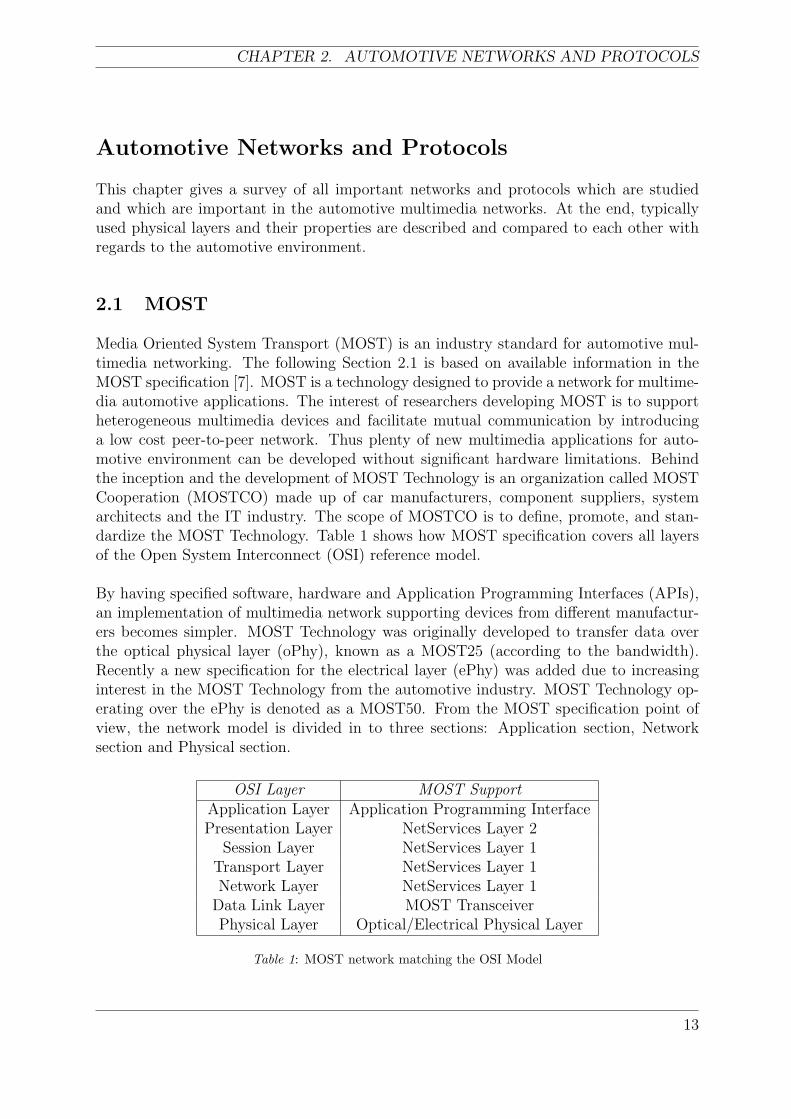
Media Oriented System Transport (MOST) is an industry standard for automotive mul-timedia networking. The following Section 2.1 is based on available information in theMOST specification [7]. MOST is a technology designed to provide a network for multime-dia automotive applications. The interest of researchers developing MOST is to supportheterogeneous multimedia devices and facilitate mutual communication by introducinga low cost peer-to-peer network. Thus plenty of new multimedia applications for auto-motive environment can be developed without significant hardware limitations. Behindthe inception and the development of MOST Technology is an organization called MOSTCooperation (MOSTCO) made up of car manufacturers, component suppliers, systemarchitects and the IT industry. The scope of MOSTCO is to define, promote, and stan-dardize the MOST Technology. Table 1 shows how MOST specification covers all layersof the Open System Interconnect (OSI) reference model.
By having specified software, hardware and Application Programming Interfaces (APIs),an implementation of multimedia network supporting devices from different manufactur-ers becomes simpler. MOST Technology was originally developed to transfer data overthe optical physical layer (oPhy), known as a MOST25 (according to the bandwidth).Recently a new specification for the electrical layer (ePhy) was added due to increasinginterest in the MOST Technology from the automotive industry. MOST Technology op-erating over the ePhy is denoted as a MOST50. From the MOST specification point ofview, the network model is divided in to three sections: Application section, Networksection and Physical section.
OSI Layer MOST SupportApplication Layer Application Programming InterfacePresentation Layer NetServices Layer 2
Session Layer NetServices Layer 1Transport Layer NetServices Layer 1Network Layer NetServices Layer 1
Data Link Layer MOST TransceiverPhysical Layer Optical/Electrical Physical Layer
Table 1: MOST network matching the OSI Model
13
ANALYSIS OF MULTIMEDIA NETWORKS FOR AUTOMOTIVE APPLICATIONS
2.1.1 Application Section
The MOST network supports various devices with wide range of functionality. Startingwith simple audio devices like microphones and speakers, MOST networks include videocameras culminating with sophisticated telematics systems. Three different data channelsare available for applications:
• Control Channel – The control channel is dedicated for event-oriented transmissionwith low bandwidth (10 kbit/s) and short packet length. ACK/NAK mechanism isintroduced together with CRC secured channels.
• Synchronous Channel – Applications using continuous data streams that requirehigh bandwidth make use of the synchronous channel. Connection and bandwidthadministration are done via Connection manager. Requests for establishing connec-tions are addressed to this block. The Connection manager uses functions defined ina FBlock ConnectionMaster, which is a compulsory FBlock for each system usuallyplaced in the Timing master device (see example in section 4.2.3).
• Asynchronous Channel – Data are transmitted in a burst-like manner in large blocksize with large bandwidth.
Logical device model: To connect a device to the MOST Network, each device needsto be equipped with a Network Interface Controller (NIC). From the MOST Network’spoint of view every device consists of a Physical Interface, a NIC and particular Functionblocks.
Functions: Functions are accessible from outside the Function block via the FunctionInterface (FI) and can be further divided into three groups (depending on what kind ofoperation they perform):
• Methods are defined as functions which can be started and which lead to the resultafter a certain period of time. Generally they are triggered only once and are used tocontrol the FBlocks. After a method is called, depending on what kind of operationtype we use (e.g. start, start/result [7]), the error or report message should be sentto the initiator.
• Properties are functions used to change the status of a device i.e. the property of adevice. The Operation Types for the properties are: get, set, increment, etc. Everyproperty has a one unique state.
• Events are basically the same as properties, the only distinction is that events occurwithout any external request (e.g. incoming phone call).
Function Block: Each FBlock contains functions. Every device has several FBlocksrepresenting the applications (e.g. CD player, amplifier, etc.) and one mandatory FBlockcalled Netblock, maintaining functions related to the entire device. We have three differenttypes of FBlocks: slaves, controllers and HMIs. Slaves are always controlled FBlocks,controllers are FBlocks using functions in another Function Block and HMIs are FBlockscommunicating with the user. By using the delegation, heredity and device hierarchymethods, the complex system can be controlled in an understandable way [7].
14
CHAPTER 2. AUTOMOTIVE NETWORKS AND PROTOCOLS
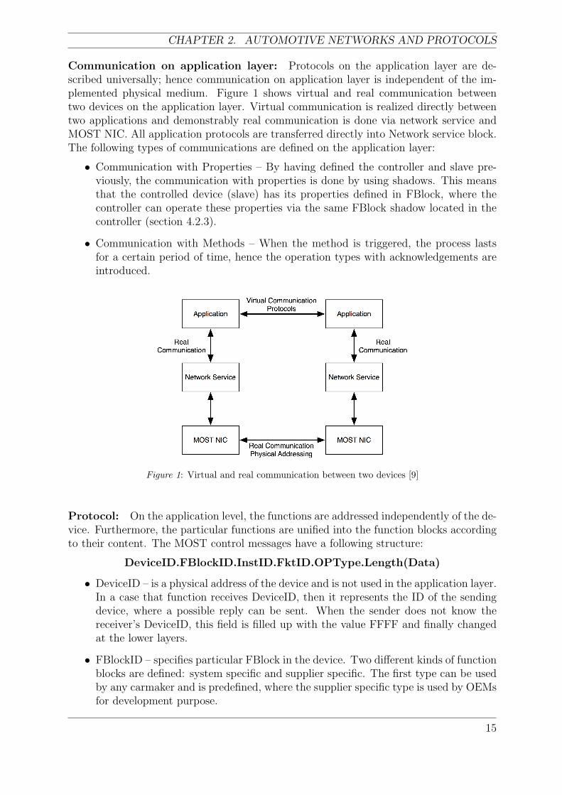
Communication on application layer: Protocols on the application layer are de-scribed universally; hence communication on application layer is independent of the im-plemented physical medium. Figure 1 shows virtual and real communication betweentwo devices on the application layer. Virtual communication is realized directly betweentwo applications and demonstrably real communication is done via network service andMOST NIC. All application protocols are transferred directly into Network service block.The following types of communications are defined on the application layer:
• Communication with Properties – By having defined the controller and slave pre-viously, the communication with properties is done by using shadows. This meansthat the controlled device (slave) has its properties defined in FBlock, where thecontroller can operate these properties via the same FBlock shadow located in thecontroller (section 4.2.3).
• Communication with Methods – When the method is triggered, the process lastsfor a certain period of time, hence the operation types with acknowledgements areintroduced.
Figure 1: Virtual and real communication between two devices [9]
Protocol: On the application level, the functions are addressed independently of the de-vice. Furthermore, the particular functions are unified into the function blocks accordingto their content. The MOST control messages have a following structure:
DeviceID.FBlockID.InstID.FktID.OPType.Length(Data)
• DeviceID – is a physical address of the device and is not used in the application layer.In a case that function receives DeviceID, then it represents the ID of the sendingdevice, where a possible reply can be sent. When the sender does not know thereceiver’s DeviceID, this field is filled up with the value FFFF and finally changedat the lower layers.
• FBlockID – specifies particular FBlock in the device. Two different kinds of functionblocks are defined: system specific and supplier specific. The first type can be usedby any carmaker and is predefined, where the supplier specific type is used by OEMsfor development purpose.
15
ANALYSIS OF MULTIMEDIA NETWORKS FOR AUTOMOTIVE APPLICATIONS
• InstID – is an identifier of instance of function block. If the FBlockID is not uniquewithin the system this identifier specifies the function block. FBlockID and InstIDcreate the functional address, which has to be unique.
• FktID – This part of the protocol constitutes a function (e.g. change CD track, stopetc.). Functions are divided into the following 6 groups: coordination, mandatory,extensions, unique, and system and supplier specific [7].
• OPType – operation type specifies the operations applicable to the functions (e.g.set, get, increment etc).
• Length – indicates the size of the control packet. This parameter is not transferredthrough the control channel, but is computed in the receiving node.
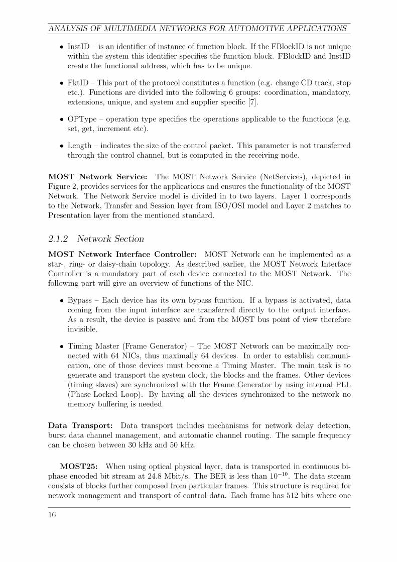
MOST Network Service: The MOST Network Service (NetServices), depicted inFigure 2, provides services for the applications and ensures the functionality of the MOSTNetwork. The Network Service model is divided in to two layers. Layer 1 correspondsto the Network, Transfer and Session layer from ISO/OSI model and Layer 2 matches toPresentation layer from the mentioned standard.
2.1.2 Network Section
MOST Network Interface Controller: MOST Network can be implemented as astar-, ring- or daisy-chain topology. As described earlier, the MOST Network InterfaceController is a mandatory part of each device connected to the MOST Network. Thefollowing part will give an overview of functions of the NIC.
• Bypass – Each device has its own bypass function. If a bypass is activated, datacoming from the input interface are transferred directly to the output interface.As a result, the device is passive and from the MOST bus point of view thereforeinvisible.
• Timing Master (Frame Generator) – The MOST Network can be maximally con-nected with 64 NICs, thus maximally 64 devices. In order to establish communi-cation, one of those devices must become a Timing Master. The main task is togenerate and transport the system clock, the blocks and the frames. Other devices(timing slaves) are synchronized with the Frame Generator by using internal PLL(Phase-Locked Loop). By having all the devices synchronized to the network nomemory buffering is needed.
Data Transport: Data transport includes mechanisms for network delay detection,burst data channel management, and automatic channel routing. The sample frequencycan be chosen between 30 kHz and 50 kHz.
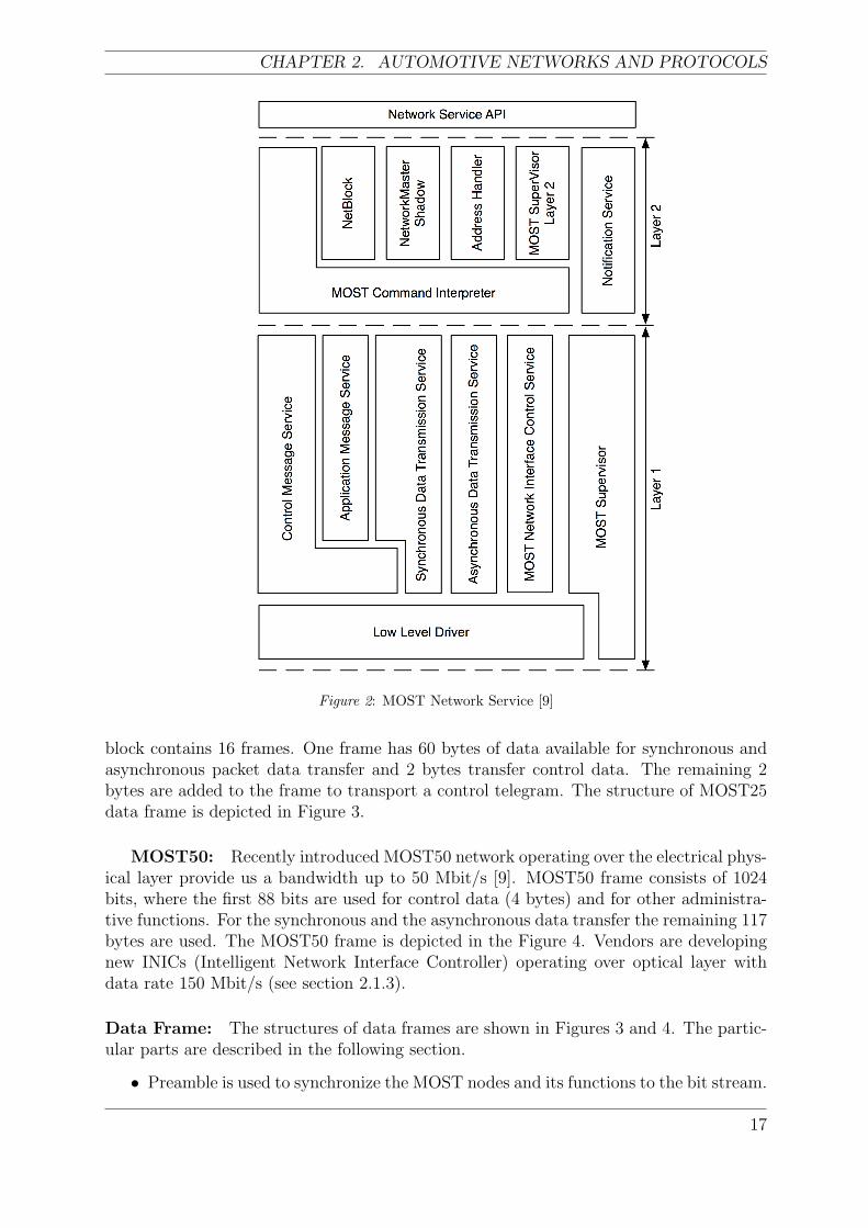
MOST25: When using optical physical layer, data is transported in continuous bi-phase encoded bit stream at 24.8 Mbit/s. The BER is less than 10−10. The data streamconsists of blocks further composed from particular frames. This structure is required fornetwork management and transport of control data. Each frame has 512 bits where one
16
CHAPTER 2. AUTOMOTIVE NETWORKS AND PROTOCOLS
Figure 2: MOST Network Service [9]
block contains 16 frames. One frame has 60 bytes of data available for synchronous andasynchronous packet data transfer and 2 bytes transfer control data. The remaining 2bytes are added to the frame to transport a control telegram. The structure of MOST25data frame is depicted in Figure 3.
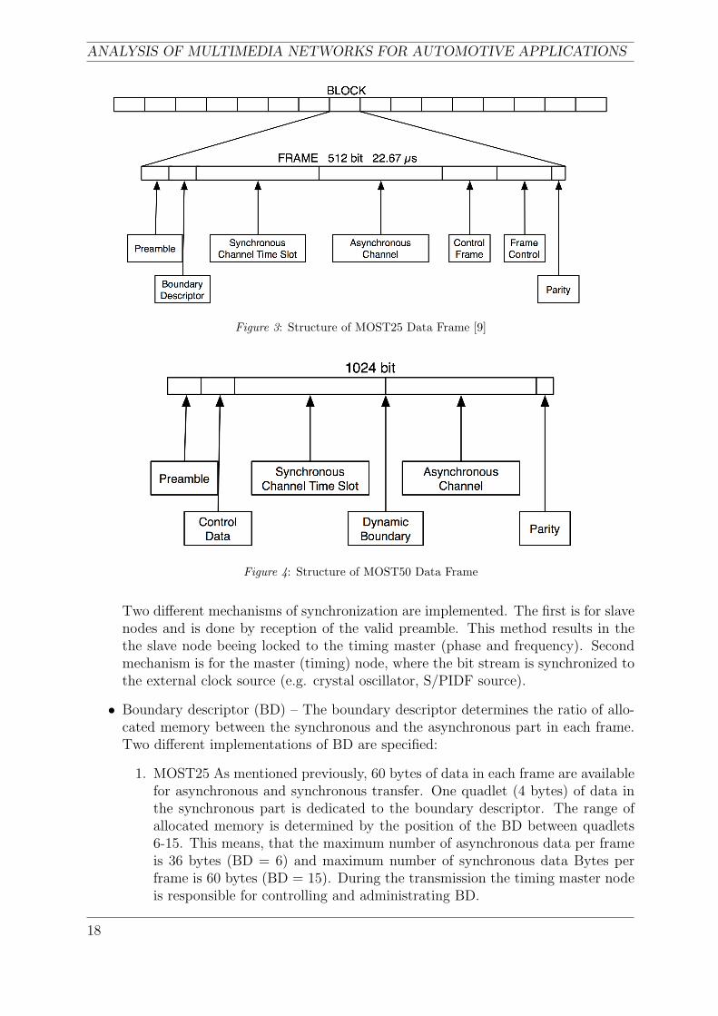
MOST50: Recently introduced MOST50 network operating over the electrical phys-ical layer provide us a bandwidth up to 50 Mbit/s [9]. MOST50 frame consists of 1024bits, where the first 88 bits are used for control data (4 bytes) and for other administra-tive functions. For the synchronous and the asynchronous data transfer the remaining 117bytes are used. The MOST50 frame is depicted in the Figure 4. Vendors are developingnew INICs (Intelligent Network Interface Controller) operating over optical layer withdata rate 150 Mbit/s (see section 2.1.3).
Data Frame: The structures of data frames are shown in Figures 3 and 4. The partic-ular parts are described in the following section.
• Preamble is used to synchronize the MOST nodes and its functions to the bit stream.
17
ANALYSIS OF MULTIMEDIA NETWORKS FOR AUTOMOTIVE APPLICATIONS
Figure 3: Structure of MOST25 Data Frame [9]
Figure 4: Structure of MOST50 Data Frame
Two different mechanisms of synchronization are implemented. The first is for slavenodes and is done by reception of the valid preamble. This method results in thethe slave node beeing locked to the timing master (phase and frequency). Secondmechanism is for the master (timing) node, where the bit stream is synchronized tothe external clock source (e.g. crystal oscillator, S/PIDF source).
• Boundary descriptor (BD) – The boundary descriptor determines the ratio of allo-cated memory between the synchronous and the asynchronous part in each frame.Two different implementations of BD are specified:
1. MOST25 As mentioned previously, 60 bytes of data in each frame are availablefor asynchronous and synchronous transfer. One quadlet (4 bytes) of data inthe synchronous part is dedicated to the boundary descriptor. The range ofallocated memory is determined by the position of the BD between quadlets6-15. This means, that the maximum number of asynchronous data per frameis 36 bytes (BD = 6) and maximum number of synchronous data Bytes perframe is 60 bytes (BD = 15). During the transmission the timing master nodeis responsible for controlling and administrating BD.
18
CHAPTER 2. AUTOMOTIVE NETWORKS AND PROTOCOLS
2. MOST50 A dynamic boundary method is used in the MOST50 frame. Thedynamic boundary allows the system to dynamically change the streaming dataduring the data transfer. The only authorized device to realize this change isan application in the timing master. The maximum amount of data for packetoriented transfer is 116 bytes/frame.
• Parity – A parity control frame is employed to control the content of data, errordetection and PLL operation.
• Synchronous area – Allocated time slots in the synchronous channel are used forreal-time data transmission (audio/video, monitoring, sensors). The Time DivisionMultiplex (TDM) method with allocation of quasi-static physical channels for dif-ferent periods of time technique is implemented. The MOST25 has available up to480 bits/frame with the data rate 44 100 frames/s and the MOST50 network enableat maximum 936 bits/frame with 48 000 frames/s.
• Asynchronous area – The asynchronous (packet) data can be transmitted in twodifferent ways. Firstly in order to transfer a slow asynchronous data (e.g. telegramsto control devices) the control channel is used. Secondly, faster packet-orientedtransfer is done via an asynchronous channel designed to handle burst like traffic.The access method for this channel is implemented in token ring fashion (i.e. a‘token’ is passed from one node to another and authorizes a device to send a data)and the maximum packet length is 48 bytes. Hardware CRC protection is calculatedand is assigned to the end of each asynchronous message.
• Control data – For communication between single nodes on the bus the controldata channel is used. The Carrier Sense Multiple Access (CSMA) mechanism isemployed for accessing the data channel. Two kinds of control messages are used.Normal messages to provide a control of applications (commands, status and diag-nosis messages) and system messages for system administration (resource handling).Arbitration is provided automatically by MOST NIC.
Addressing: Addressing is provided by the MOST Network Interface Controller in fourdifferent versions [9]):
• Node position in the network – Automatic generating of the possition during thelocking procedure.
• Unique node address (2 bytes) – An application can set unique address to a certainnode.
• Group address – Devices with the same address numbers create a group. The groupaddresses can be used to control devices with the same features (e.g. speakers).
• Broadcast – The broadcast message is sent to all nodes in the network. During thebroadcast message a control channel is locked for all other communication messages,until the acknowledgement from last device for broadcast is received.
19
ANALYSIS OF MULTIMEDIA NETWORKS FOR AUTOMOTIVE APPLICATIONS
Channel administration: The following internal services are implemented in the MOSTNetwork to provide functional data transfer and to allocate necessary timeslots for sy-chronous and asynchornous data.
1. MOST25
• System Startup – When the network is established every device receives aunique number starting with Timing Master 0x00 and then incremented byone for each next device. At the end of this procedure, the final value isdistributed over the network (i.e. every connected device knows how manydevices are connected to the bus).
• Delay recognition – Each NIC has information about the source data delay. Bytaking into consideration the fact that each device can operate in passive oractive mode (bypass is open or close), every active device creates two framesof delay.
• Detection of unused channels – The timing master device can establish if thereare some unused channels (i.e. allocated channels without any data transfer).By using resource allocation, the table re-allocation of unused channels can berecommended.
• Automatic channel allocation – To allocate a channel each device has to send arequest to the timing master device. As a reply an information about availablechannel is sent.
2. MOST50
• System Startup (see MOST25)
• Delay recognition – The delay in the MOST50 network caused by the processingis negligible, due to the faster processing procedures (no optoelectronic con-verters are needed). Therefore no delay recognition methods are implementedand all devices are pernamently active.
• Automatic channel allocation – In order to allocate the bandwidth a socketis created and its size determines the amount of allocated bandwidth. Whenthe socket is destroyed the bandwidth is de-allocated and no mechanism fordetection of unused channels is necessary.
2.1.3 Physical Section
The following text describes particular parts of the MOST device structure.
• Interface Area – Consists of a transmitter (TX) and a receiver (RX) communicatingwith the NIC. During a data transmission the phase jitter can be accumulated,hence the phase jitter together with power budget are considered during the designof Interface Area.
• MOST Function Area – The Network Interface Controller, crystal and PLL-Filterare the main blocks in the MOST Function Area. The NIC communicates withthe µController via the I2C (Inter-Integrated Circuit), the SPI (Serial PeripheralInterface) or a parallel bus.
20
CHAPTER 2. AUTOMOTIVE NETWORKS AND PROTOCOLS
• µController Area usually consists of the microcontroller (µC) and the memory.
• Application Area belongs to the application peripherals (i.e., receiver, amplifier).
• Power Supply Area consists of different facilities performing various tasks (e.g.EMI/EMC protection, micropower regulator, etc [7]).
Optical Physical Layer: As mentioned earlier, the MOST Network was originally de-veloped and designed to operate over plastic optical fibres (POFs) as a physical layer. Inthat time the certain advantages were Electro-Magnetic Interference (EMI) immunity andlight weight. On the other hand, small bend radius and limited temperature range werethe two most significant imperfections from the automotive point of view [35]. MOSTTechnology utilization was increasing by implementing it into luxury modern cars. Theused optical medium for the MOST25 is POF (see section 2.5.2).
Electrical Physical Layer: The automotive industry is becoming more and more fo-cused on the electronic area and carmakers are competing against each other in providingsuperior and more sophisticated multimedia services. Under these conditions the needsfor multimedia services in budget-range cars and for new electrical physical layer arise.Simultaneously with a new electrical physical layer the INIC 5 was introduced [22]. As atransmission medium Unshielded Twist Pair (UTP) cables are employed.
EMC Testing The following part summarizes the most significant improvementsin order to increase EMC in ePHY. These improvements enabled to use ePhy in theautomotive environment with high EMI.
• The signal skew of differential transmission was reduced by common mode filter[21].
• The power between physical layer and NIC was decreased (from 5 V to 3,3 V and2,5 V [27]).
• Differential signalling, filtering and scrambling of the signal was introduced.
• The size and number of high-speed traces in Printed Circuit Board were reduced.
MOST50 was individually tested by several carmakers. The list of the passed standardscan be found in [8]. Different kinds of UTP cables with a twist length of ≤45 mmand impedance of 100 Ω were tested. Standard automotive connectors (e.g. crimp styleconnector with 4 or more pins [8]) can be used.
The INIC for MOST was designed to facilitate the integration of the new electricalphysical layer. Significant benefits are:
• Doubled transmission rate from 25 Mbit/s to 50 Mbit/s in MOST50 [12].
• High number of interconnects (up to 8 in-line couplers per link between 2 devices).
• Utilization of current manufacturing processes (UTP cables).
• Simple manipulation.
21
ANALYSIS OF MULTIMEDIA NETWORKS FOR AUTOMOTIVE APPLICATIONS
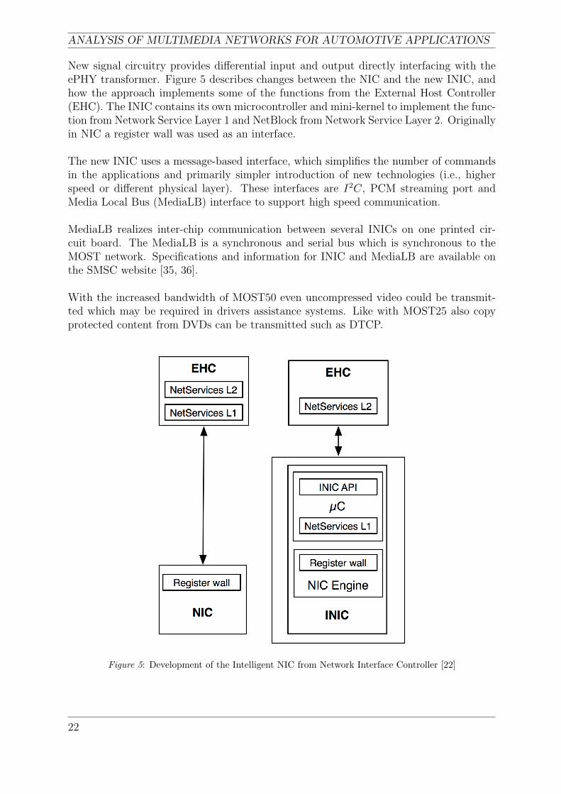
New signal circuitry provides differential input and output directly interfacing with theePHY transformer. Figure 5 describes changes between the NIC and the new INIC, andhow the approach implements some of the functions from the External Host Controller(EHC). The INIC contains its own microcontroller and mini-kernel to implement the func-tion from Network Service Layer 1 and NetBlock from Network Service Layer 2. Originallyin NIC a register wall was used as an interface.
The new INIC uses a message-based interface, which simplifies the number of commandsin the applications and primarily simpler introduction of new technologies (i.e., higherspeed or different physical layer). These interfaces are I2C, PCM streaming port andMedia Local Bus (MediaLB) interface to support high speed communication.
MediaLB realizes inter-chip communication between several INICs on one printed cir-cuit board. The MediaLB is a synchronous and serial bus which is synchronous to theMOST network. Specifications and information for INIC and MediaLB are available onthe SMSC website [35, 36].
With the increased bandwidth of MOST50 even uncompressed video could be transmit-ted which may be required in drivers assistance systems. Like with MOST25 also copyprotected content from DVDs can be transmitted such as DTCP.
Figure 5: Development of the Intelligent NIC from Network Interface Controller [22]
22
CHAPTER 2. AUTOMOTIVE NETWORKS AND PROTOCOLS
Future trends: As it was stated, the MOST Network is a dynamically developingtechnology. This paragraph draws up the future development trends and directions.
• MOST150 is the next step in the development process with a higher bandwidth (150Mbit/s) based still on the POF/LED. Carmakers like BMW or Daimler Chryslertend towards this solution, since the already well known and tested POF/LED canbe utilized. However 150 Mbit/s seems to be the highest possible value over POFand LED. For more bandwidth a new optical transceivers will be used. It is expected,that the MOST150 ring will transfer multiple sound and compressed video signalssimultaneously.
• MOST1000 – In order to increase the bandwidth, the PCS/VCSEL physical layer(see 2.5.2) will be utilized. The MOST1000 is a technology for long time consider-ation and its introduction is not expected within the next 10 years.
2.2 IDB-1394
IDB-1394 is an automotive version of the IEEE-1394b standard, a high-speed bidirectionalserial bus usually used for digital video cameras, hard discs and other high-speed devices,extended by higher level protocols [25]. For automotive applications either POF or hardclad silica fibres (HCS) are applicable. Depending on the physical medium, maximumtransmission rates of 100 Mbit/s and 200 Mbit/s over a link length of 50 m (POF) and100 m (HCS). Using shorter link lengths increases the transmission rate up to 400 Mbit/sand soon up to 1600 and even 3200 Mbit/s.
The standard supports up to 63 nodes per bus including a consumer convenience port,automatic node identification and topology configuration. IEEE-1394 also supports bothasynchronous traffic and isochronous traffic with guaranteed latency and bandwidth whichmakes it suitable for real-time applications. The physical topology of IEEE-1394 can bea bus or ”daisy-chain” or a tree. In the automotive version IDB-1394 a ring topology ispossible too, which is the suggested topology here as it provides a reliable level of systemavailability because the communication between the devices is not interrupted as long asnot more than one link is faulty. Each IEEE-1394 device provides at least two connectors.
2.2.1 IDB-1394 Specification
IDB-1394 specifies OSI layer one to layer four. The first three layers, except the IDB-1394protocol itself, which is a part layer three, also meet the IEEE-1394 specifications [19].The following list shows the different protocol layers of IDB-1394.
• Physical Layer including the CCP ( which provides an interface, used for portabledevices)
• IEEE-1394 stack and driver: The driver acts as the hardware device driver whereasthe stack is responsible for bus management, isochronous resource management andisochronous and asynchronous transaction management.
• Higher-level protocols: These protocols include the communication managementprotocol IEC-61883, which defines the format in which audio and video data are
23
ANALYSIS OF MULTIMEDIA NETWORKS FOR AUTOMOTIVE APPLICATIONS
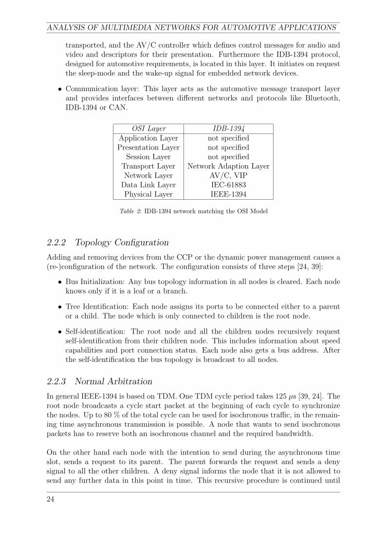
transported, and the AV/C controller which defines control messages for audio andvideo and descriptors for their presentation. Furthermore the IDB-1394 protocol,designed for automotive requirements, is located in this layer. It initiates on requestthe sleep-mode and the wake-up signal for embedded network devices.
• Communication layer: This layer acts as the automotive message transport layerand provides interfaces between different networks and protocols like Bluetooth,IDB-1394 or CAN.
OSI Layer IDB-1394Application Layer not specifiedPresentation Layer not specified
Session Layer not specifiedTransport Layer Network Adaption LayerNetwork Layer AV/C, VIP
Data Link Layer IEC-61883Physical Layer IEEE-1394
Table 2: IDB-1394 network matching the OSI Model
2.2.2 Topology Configuration
Adding and removing devices from the CCP or the dynamic power management causes a(re-)configuration of the network. The configuration consists of three steps [24, 39]:
• Bus Initialization: Any bus topology information in all nodes is cleared. Each nodeknows only if it is a leaf or a branch.
• Tree Identification: Each node assigns its ports to be connected either to a parentor a child. The node which is only connected to children is the root node.
• Self-identification: The root node and all the children nodes recursively requestself-identification from their children node. This includes information about speedcapabilities and port connection status. Each node also gets a bus address. Afterthe self-identification the bus topology is broadcast to all nodes.
2.2.3 Normal Arbitration
In general IEEE-1394 is based on TDM. One TDM cycle period takes 125 µs [39, 24]. Theroot node broadcasts a cycle start packet at the beginning of each cycle to synchronizethe nodes. Up to 80 % of the total cycle can be used for isochronous traffic, in the remain-ing time asynchronous transmission is possible. A node that wants to send isochronouspackets has to reserve both an isochronous channel and the required bandwidth.
On the other hand each node with the intention to send during the asynchronous timeslot, sends a request to its parent. The parent forwards the request and sends a denysignal to all the other children. A deny signal informs the node that it is not allowed tosend any further data in this point in time. This recursive procedure is continued until
24
CHAPTER 2. AUTOMOTIVE NETWORKS AND PROTOCOLS
the root node is reached. The root node grants the request and sends a deny signal tothe other children. Finally the node, which received the grant signal, propagates the dataprefix signal throughout the rest of the network followed by the data bytes [39].
2.2.4 Performance
The effects of isochronous traffic on asynchronous traffic and the fairness protocol ofthe arbitration mechanism are analyzed in [39]. Test measurements showed that theasynchronous traffic was unaffected by the isochronous real-time traffic and vice versa aslong as the total bus utilization was below 80 %. At a higher load the asynchronous trafficdecreased but the isochronous data continued without incident.
2.2.5 VersaPHY
The VersaPHY was recently introduced by the 1394 Trade Association. This standardprovides the same data rate and cable lengths like the existing IEEE-1394 standard and itis also compatible with it. The advantage of this protocol is the reduction of ”unnecessaryoverhead” [10]. Cost for the controller chips are reduced, as not the whole protocol mustbe implemented in a VersaPHY device. Link, transaction and management layers canbe avoided and the necessary functionality will be integrated in an expanded physicallayer. Therefore devices without complex software, controllers or microcontrollers likesensors, actuators, microphones, loudspeakers and cameras can be connected via thismore USB-like approach. On the other hand both asynchronous communication andguaranteed real-time streaming are still supported. An implementation of this protocolinto automotive networks is suggested by the developers.
2.3 SAE J1939
The CAN-based SAE J1939 bus was developed for diagnostics and component controlapplications in truck and trailer systems like radar and lidar, and engine, transmissionand EBS electronic control modules. This SAE class C network supports real-time closedloop control function between ECUs [1].
2.3.1 Physical Layer
OSI layer one and two are identical to the CAN 2.0b standard. The physical mediumcan be both, shielded (SAE J1939-11) and unshielded (SAE J1939-15) twisted pair ofcopper wires. The maximum bus length is 40 m, terminated with a resistor at each endto reduce reflections, with a maximum data rate of 250 kbit/s. The ECUs may be indirect contact with the bus, or via short stubs. No loops are allowed, although redundantbus segments can be provided for fault tolerance. In this case the corresponding ECUsmust be able to deal with these redundant wires. To provide electrical isolation andcompatibility of different data rates and physical media between segments like tractor,trailor or implements, bridges are used. J1939 supports up to 30 ECUs per bus segmentif STP wires are used, in the case of UTP this number is reduced to 10 [29, 30].
25
ANALYSIS OF MULTIMEDIA NETWORKS FOR AUTOMOTIVE APPLICATIONS
2.3.2 Data Link Layer
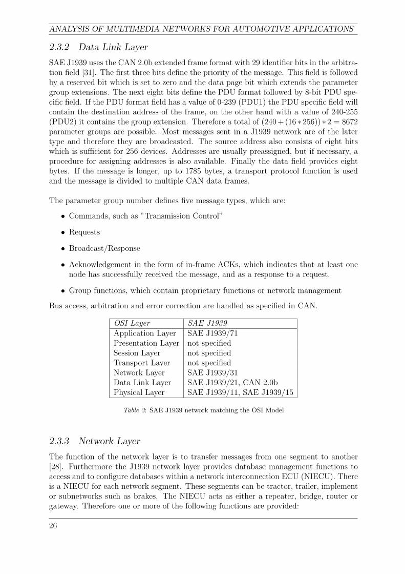
SAE J1939 uses the CAN 2.0b extended frame format with 29 identifier bits in the arbitra-tion field [31]. The first three bits define the priority of the message. This field is followedby a reserved bit which is set to zero and the data page bit which extends the parametergroup extensions. The next eight bits define the PDU format followed by 8-bit PDU spe-cific field. If the PDU format field has a value of 0-239 (PDU1) the PDU specific field willcontain the destination address of the frame, on the other hand with a value of 240-255(PDU2) it contains the group extension. Therefore a total of (240+(16∗ 256))∗ 2 = 8672parameter groups are possible. Most messages sent in a J1939 network are of the latertype and therefore they are broadcasted. The source address also consists of eight bitswhich is sufficient for 256 devices. Addresses are usually preassigned, but if necessary, aprocedure for assigning addresses is also available. Finally the data field provides eightbytes. If the message is longer, up to 1785 bytes, a transport protocol function is usedand the message is divided to multiple CAN data frames.
The parameter group number defines five message types, which are:
• Commands, such as ”Transmission Control”
• Requests
• Broadcast/Response
• Acknowledgement in the form of in-frame ACKs, which indicates that at least onenode has successfully received the message, and as a response to a request.
• Group functions, which contain proprietary functions or network management
Bus access, arbitration and error correction are handled as specified in CAN.
OSI Layer SAE J1939Application Layer SAE J1939/71Presentation Layer not specifiedSession Layer not specifiedTransport Layer not specifiedNetwork Layer SAE J1939/31Data Link Layer SAE J1939/21, CAN 2.0bPhysical Layer SAE J1939/11, SAE J1939/15
Table 3: SAE J1939 network matching the OSI Model
2.3.3 Network Layer
The function of the network layer is to transfer messages from one segment to another[28]. Furthermore the J1939 network layer provides database management functions toaccess and to configure databases within a network interconnection ECU (NIECU). Thereis a NIECU for each network segment. These segments can be tractor, trailer, implementor subnetworks such as brakes. The NIECU acts as either a repeater, bridge, router orgateway. Therefore one or more of the following functions are provided:
26
CHAPTER 2. AUTOMOTIVE NETWORKS AND PROTOCOLS
• Forwarding messages from one segment to another segment
• Filtering to reduce bus traffic on a given segment as messages which are not meantfor a segment can be blocked by the NIECU
• Address Translation, where a single address can be used to reference a particularsystem like the trailer, due to a look-up table with the associated source/destinationaddress located in the NIECU
• Message Repackaging, which provides a potential reduction of bus traffic as severalparameters can be grouped more efficiently
• Database Management to access and configure databases in the NIECU such as thestatic filter database
2.3.4 Vehicle Application Layer
In the vehicle application layer of SAE J1939 all the parameter groups as well as theparameter group numbers are specified. The parameter group number is a unique iden-tifier for each CAN message [33]. Furthermore a ”source address of controlling device”parameter was added in the last revision which makes it possible to identify the originalsource of a message in a bridged network.
2.3.5 Network Management
The Network management covers all OSI layers [32]. This layer defines various statediagrams for instance for initialization and it defines constraints on the use of addresses.
2.4 APIX Link
The Automotive PIXel Link was developed by Inova Semiconductors [15, 17, 34] in coop-eration with the Fraunhofer Gesellschaft in spring 2005. The link was the answer to thecar industry’s question if GigaSTaR (Gigabit-Serial-Transmit and Receive), which offersdata rates of up to 1.2 Gbit/s over a pair of copper wires, can be used in automotiveapplications. GigaSTaR is currently utilized for passenger information systems in trains,to connect remote terminals in the automation industry, as well as for modern LED videowalls. The high requirements of the car industry concerning EMI and EMC were notfulfilled by GigaSTaR. Therefore Inova Semiconductors developed APIX to meet thesedemands.
The APIX point-to-point link is based on one or two pairs of STP copper wires andtransmits uncompressed pixel data with a data rate of up to 1 Gbit/s on the downlinkand up to 62.5 Mbit/s on the upstream link over a wire length of 15 m. One big advantageof APIX compared to optical networks like MOST or IDB-1394 is that optical-to-electronicand electronic-to-optical converters on each device, which produces rather high cost, andcomparable unflexible POFs can be avoided. The transceiver and receiver chips are pro-duced in a 0.18-µm-CMOS process which keeps the purchasing costs low. Also the energyconsumption is as low as 200 mW and the possible application area covers a temperature
27
ANALYSIS OF MULTIMEDIA NETWORKS FOR AUTOMOTIVE APPLICATIONS
range from -40 C to 105 C [16].
Due to special IOs, adjustable driving current and pre-emphasis, new spread-spectrumclocking and an optimized PLL concept, a very good electromagnetical compatibility ofthe link is ensured. The APIX link only specifies the physical layer.
APIX provides a continuous real-time data stream with low latency and low BER, runningfor instance at 1 Gbit/s for the high-resolution, full-colour display link between an imageprocessor and a TFT display or 500 Mbit/s on a camera link between a CMOS sensorand the processor. The camera can be monitored and controlled with the integrated backchannel simultaneously. Altogether the APIX link consists of three independent channels:the unidirectional downstream pixel channel and the bidirectional side band channels. Allchannels can be multiplexed and transmitted over a single STP wire. The upstream sideband channel could also be established over a second pair of wires. One application forthese additional side band channels is to transmit other protocols ’piggyback-like’ withoutthe need of buffers. These protocols can be used to monitor and control parameters ofthe CMOS sensors and displays.
Applications for the APIX link as proposed by Inova Semiconductors are for instancedashboard, rear seat, or head-up displays as well as cameras for lane departure warning,adaptive cruise control, rear and side mirror replacement and blind spot detection. Large24-bit full-colour displays with a resolution of 1280-by-480 pixels have the potential toreplace the analogue dashboard in the near future.
Press releases such as [16] claim that APIX’ safe and EMC-optimized physical layer willbe a good basis to meet the requirements for the next decade. A large number of suppliershave already started to integrate the APIX functionality in their chip sets.
2.5 Physical Layer
2.5.1 Electrical Medium
Physical Layer Requirements: The use of an electrical physical layer in the formof a shielded or unshielded twisted pair of copper wires is preferred as it represents thecheapest form of wiring. Due to the extreme conditions in the automotive environmentconcerning EMC and EMI the research has been concentrated for optical media in thepast. The development of adaptive chips as used for MOST50 with ePHY or the APIXlink, makes U/STP cabling interesting again even for very high data rates. Anotheradvantage is that the copper wires are insensitive to temperature and as they are thesame as used for the CAN/J1939 network, there are no problems with laying the cabling,as no bending radii have to be considered.
2.5.2 Optical Medium
In the past the car industry held the view that copper wires would never meet the require-ments for high-speed links in vehicles. Therefore most of the research was concentratedon the development of optical fibers. Basically there are two important combinations of
28
CHAPTER 2. AUTOMOTIVE NETWORKS AND PROTOCOLS
fibers and transmitters.
POF and LED: Most in-vehicle optical networks including d2B and MOST use a com-bination of PMMA (PolyMethyl MethAcrylate) Plastic Optical Fibers (POFs) with redLED transmitters operating at 650 nm [40],[42]. This combination brings some limita-tions. PMMA fibers can only be utilized in applications inside the passenger compartmentas they would be destroyed by temperatures higher than 85 C which occur in the enginecompartment or the roof. Due to high insertion losses in the fibers, connectors and pas-sive couplers, only point-to-point and no passive fail-tolerant topologies are possible. Themaximum data rate using these components is ≤ 150 Mbit/s over a maximum link lengthof 20 m due to a lack of low-cost temperature-stable red transmitters and large-area highsensitive receivers.
HCS and VCSEL: A possible improvement to the combination of POF and LED isrecommended by [40]. The use of HCS (Hard Clad Silica) fibers and VCSEL (vertical-cavity surface-emitting laser) transmitters operating at 850 nm instead of PMMA fibersand red LEDs respectively brings a much higher temperature resistance up to 125 C.Also the fiber attenuation is negligible for typical link lengths in applications such ascars, trucks, buses and even aircraft. This combination allows even passive star coupledoptical in-vehicle data networks, as a large system margin of 25 dB has been demonstratedfor point-to-point links in a temperature range of -40 C to 85 C and a data rate of 622MBit/s. The cost of of such a optical link is noticeable higher than the combination ofPOF and LED.
2.5.3 Cable Comparison
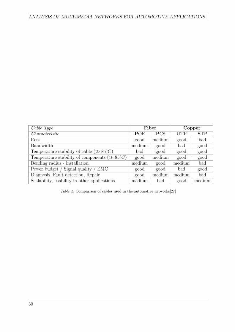
Table 4 compares the suitable physical media for automotive multimedia networks withvarious aspects. These aspects are the most important during an implementation pro-cess. Table 4 is taken from [27]. It is not possible to choose one cable which is best in allregards. In order to decide which cable to use, the characteristics have to be comparedwith the particular demands and environment in which the network will be implemented.In conclusion, the particular cables we should consider are the cables with points markedas a ‘bad’. STP cable appears to be a possibility worth considering. Better propertiescharacterize UTP cable and not very far from UTP copper cable, the POF and PCScables are located.
Another aspect related to this issue is the weight of cables in the vehicles. BMW de-scribes the automotive ring as the best topology for decreasing the weight and number oftransceivers, compared with the star topologies [27].
29
ANALYSIS OF MULTIMEDIA NETWORKS FOR AUTOMOTIVE APPLICATIONS
Cable Type Fiber CopperCharacteristic POF PCS UTP STPCost good medium good badBandwidth medium good bad goodTemperature stability of cable ( 85C) bad good good goodTemperature stability of components ( 85C) good medium good goodBending radius - installation medium good medium badPower budget / Signal quality / EMC good good bad goodDiagnosis, Fault detection, Repair good medium medium badScalability, usability in other applications medium bad good medium
Table 4: Comparison of cables used in the automotive networks[27]
30
CHAPTER 3. PERFORMANCE REQUIREMENTS
3 Performance Requirements
31

ANALYSIS OF MULTIMEDIA NETWORKS FOR AUTOMOTIVE APPLICATIONS
32
CHAPTER 3. PERFORMANCE REQUIREMENTS
Performance Requirements
An important aspects, which influence the development process of automotive electronicsand automotive multimedia networks are introduced in this part.
3.1 Performance Requirements and Characteristics of Automo-tive Multimedia Systems
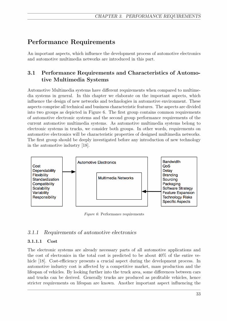
Automotive Multimedia systems have different requirements when compared to multime-dia systems in general. In this chapter we elaborate on the important aspects, whichinfluence the design of new networks and technologies in automotive environment. Theseaspects comprise all technical and business characteristic features. The aspects are dividedinto two groups as depicted in Figure 6. The first group contains common requirementsof automotive electronic systems and the second group performance requirements of thecurrent automotive multimedia systems. As automotive multimedia systems belong toelectronic systems in trucks, we consider both groups. In other words, requirements onautomotive electronics will be characteristic properties of designed multimedia networks.The first group should be deeply investigated before any introduction of new technologyin the automotive industry [18].
Figure 6: Performance requirements
3.1.1 Requirements of automotive electronics
3.1.1.1 Cost
The electronic systems are already necessary parts of all automotive applications andthe cost of electronics in the total cost is predicted to be about 40% of the entire ve-hicle [18]. Cost-efficiency presents a crucial aspect during the development process. Inautomotive industry cost is affected by a competitive market, mass production and thelifespan of vehicles. By looking further into the truck area, some differences between carsand trucks can be derived. Generally trucks are produced as profitable vehicles, hencestricter requirements on lifespan are known. Another important aspect influencing the
33
ANALYSIS OF MULTIMEDIA NETWORKS FOR AUTOMOTIVE APPLICATIONS
cost from long term point of view is, that the new technology has to satisfy the require-ments of the future development process. Generally, the automotive producers want tobe as cost-efficient as possible. Hence they aim to decrease development, production andmaintenance costs of their products on the lowest possible level. An important point isto consider that the cost-efficient system also has to satisfy its future requirements.
3.1.1.2 Dependability
Dependability can be further divided into the following aspects [18].
• Reliability and Availability- both factors are closely related to each other. Never-theless one important divergence is that reliability guarantees correct functioningover a given period of time and availability guarantees this operation at any time.
• Safety is undoubtedly a decisive factor when choosing a new technology. Whenhaving a safety parameter in mind, one can think about faults, errors and systemfailures [18].
• Confidentiality is a crucial aspect in the competitive automotive industry. Thereforeit is not convenient to disclose any confidential information, unless it is a purposefulstep, where the informations are shared (e.g. platforms in the car industry).
• Maintainability is an important factor for seamless functioning during the productlifetime. Maintainable system should also provide the possibility of various repairs,improvements and changes.
3.1.1.3 Flexibility
Flexible arrangement of the system provides the possibility to improve and change existingfunctionality and topology. A flexible arrangement can be achieved by using platformsand layered structures. Flexibility is important for automotive electronics as well as formultimedia networks. A flexible system usually decreases the cost, when the topology ischanged.
3.1.1.4 Standardization
The automotive industry needs an open standard solutions. With open standard solu-tions, the development process can be divided into more companies, hence the cost canbe decreased. As all industry developments have their own advantages and disadvan-tages, every little improvement of the open source system will be beneficial to all involvedmanufacturers, which might be undesirable. The most visible organization in automotivestandardization is AMI-C (Automotive Multimedia Interface Collaboration). It is theinterest of AMI-C to adopt already existing standards on the market to the automotiveindustry, primarily in multimedia networks (i.e. MOST, IDB 1394, Bluetooth). Stan-dardization generally refers to streaming media and communication interfaces. MOSTNetwork and AUTOSAR (AUTomotive Open System ARchitecture) are technologies de-veloped as a standard from the beginning. Behind those two projects stand differentgroups of carmakers and manufacturers.
34
CHAPTER 3. PERFORMANCE REQUIREMENTS
3.1.1.5 Compatibility
Compatibility can be increased by a standardization process (e.g. defining various in-terfaces and gateways to communicate with other external devices or systems) and is animportant aspect creating the cooperation between various producers. Generally compat-ible technology brings benefits for suppliers, automotive producers and customers.
3.1.1.6 Scalability
Scalable automotive networks are designed to increase their performance, when additionalhardware or software is added. These changes are mostly related to the future improve-ments of the electronic systems. A scalable system should satisfy requirements when newservices and technologies are introduced and implemented. Thus, researchers in automo-tive electronics aim for predicting the future trends and development as much as possibleand encompass them in the development process. Obviously this is not an easy process,since the new technologies can not be predicted. However, a reasonable trade off betweenexpected growth trends and possible current solution should be considered carefully. Inthe next sections, we will address scalability as a possibility to add new devices in to thenetwork.
3.1.1.7 Variability
Variability is defined as the capability of the system to be configurable with respect tothe special demands of the customers [41]. Electronic system must be available in variousconfigurations to be implemented in different vehicle models. In order to satisfy differentcustomers demands, the automotive manufacturer has to provide a variable configurationsof the vehicle electronic devices. The proposed multimedia network should be suitable fora different variations of electronic devices implemented in the vehicles.
3.1.1.8 Responsibility
Responsibility is an important aspect when choosing various device suppliers. If the truckmanufacturer decides to implement complex devices from external suppliers in his trucks,the responsibility for functioning of the device will rely on the suppliers. This solutionis usually not cost effective for the truck company and a reasonable trade off betweensuppliers’ products and companies’ technical solutions has to be chosen. The designedsystem can become extremely expensive, when the suppliers perform all small changes andrepairs in the system. On the other hand the technologies are usually very complex, hencethe automotive producers can not invest their resources into the development process ofall used technologies.
3.1.2 Requirements of Telematic and Infotainment systems
When having in mind the growing importance of Telematic and Infotainment systems inautomotive applications, requirements on multimedia networks driven by these systems,from the carmakers’ point of view, are highlighted in the following subsections.
35
ANALYSIS OF MULTIMEDIA NETWORKS FOR AUTOMOTIVE APPLICATIONS
3.1.2.1 Bandwidth
Bandwidth represents a major aspect in multimedia networking area. Different solutionshave been proposed in order to provide higher bandwidth and to allow superior services(e.g. streaming video). With the introduction of new network technologies the bandwidthwill unambiguously increase, since the applications demand a large amount of data to betransmitted on-board. Generally today’s state of the art does not provide satisfactorysolutions for implementing all services.
3.1.2.2 QoS
Quality of Service should be also considered when a complex multimedia network is pro-posed. By using QoS an important data can be transmitted in preference with respect tothe application.
3.1.2.3 Delay
Delay of data packets and the variance of the delay (delay jitter) plays an important role,when a real time data are transmitted. Therefore these aspects must be considered alongthe development process.
3.1.2.4 Branding
Branding is a specific industry’s requirement. When a new device is delivered by a sup-plier, the carmaker usually does not want to have a supplier’s brand written on the device.Therefore branding stands for replacing all supplier’s related trademarks and logos by car-maker’s own brand.
3.1.2.5 Power Supply
Different power supply schemes and strategies can be implemented. This factor affects thefinal solution. Generally two approaches are used. The first is to use a separate cable forthe power supply and second is to use the electrical communication medium as a sourceof energy. This can reduce a number of used cables in the vehicles, but demands morecomplicated transceivers.
3.1.2.6 Packaging
This aspect is related to different device topologies. One solution can represent a complexdevice supporting many services and other solutions can be a distributed topology of adevice providing various services not just from one device box. The complex device iseasy to implement into the vehicle, but it is not possible to change the functionality orthe topology of the system. Such a complex device can be represented by one box withall the required functions and features.
In the distributed solution, a communication network acts as a transfer medium for theparticular devices. Therefore adding new features and services is possible and all of thedevices can benefit from their mutual communication. The distributed solution bringsanother issue into the consideration as e.g. compatibility, responsibility, etc.
36
CHAPTER 3. PERFORMANCE REQUIREMENTS
3.1.2.7 Software strategy
Automotive producers have to look at heterogeneous aspects during the implementationof new technologies. The software strategy is a factor which affects other aspects such asthe cost and the packaging. Software strategy deals with different approaches with regardto the implementation of software. For instance a reasonable trade off between supplier’ssoftware implementation and the carmaker’s software solution has to be chosen. Anothercase can deal with different scenarios of how to implement the parts of the softwareinto the system (i.e. some applications can be placed in the central device and somein the particular parts in the network). The software strategy is closely related to theresponsibility, hence these aspects should be clearly defined during a cooperation with asupplier.
3.1.2.8 Feature expansion possibility
This aspect is closely related to the scalability. To emphasize the significance of scala-bility in infotainment systems, feature expansion possibility features represent importantfactors. An importance of this aspect is obvious, since the multimedia devices are dy-namically developing area and new features and functions are arising. A new introducedtechnology should be able to support functions and features introduced during the periodof its lifetime.
3.1.2.9 Technology risks
Technology risks arise when introducing new technologies which were not sufficientlytested and which e.g. are unlikely to become a standard or a major track in the industry.The automotive manufacturers are trying to avoid undesirable technology risks and arerather careful in implementing revolutionary technologies. Based on these facts, one canbegin to understand the conservatism which is prevalent in the automotive industry (e.g.vehicle’s combustion engine etc). Generally carmakers are quite conservative when itcomes to new technologies because ‘new’ implies untested and therefore unknown risks.The technology risks in the automotive industry are increased by the fact that the devicesin the vehicles are exposed to the specific conditions (e.g. temperature, vibrations, etc).
3.1.2.10 Specific Aspects
In this paragraph specific aspects which affect the development process are mentioned.These aspects are considered during the technologies development processes and are re-lated to the physical layer:
• Temperature range
• BER (Bit Error Rate)
• SNR (Signal to Noise Ratio)
• Crosstalk
• EMI (ElectroMagnetic Interference)
• Inductance
37
ANALYSIS OF MULTIMEDIA NETWORKS FOR AUTOMOTIVE APPLICATIONS
• Capacitance
3.1.3 Relations between Aspects
All aspects mentioned above should be considered carefully during a development process.Various relations between aspects can be theoretically observed and more relations appearduring the implementation procedure. Generally speaking, the most dependable aspector most related aspect in the area of multimedia networks, both from the automotivemanufacturer’s point of view is the cost (e.g. in order to have a cost-efficient productthe sufficient degree of scalability must be guaranteed). Multimedia services are thereforedependent on the customers requirements and the cost presents the most important factorfor the manufacturers.
38

CHAPTER 4. EVALUATION OF DIFFERENT TOPOLOGIES
4 Evaluation of different topologies
39

ANALYSIS OF MULTIMEDIA NETWORKS FOR AUTOMOTIVE APPLICATIONS
40
CHAPTER 4. EVALUATION OF DIFFERENT TOPOLOGIES
Evaluation of different topologies
In this chapter various networks and their topologies are described and presented as ourproposed solutions. The aspects mentioned in Part 3 are compared with the proposals.Therefore a general evaluation of the proposed networks and their comparisons is given.
4.1 CAN-based Networks
4.1.1 Typical Multimedia Topology for Trucks
Current architectures of multimedia networks in trucks, include typically an integratedCAN-based bus (e.g. J1939) as the usual communication medium. In reality the currentmultimedia network is presented by audio, phone and HMI devices connected together.In Figure 7 the typical multimedia architecture is illustrated . From Figure 7 follows theneed for changing the topology of current network. The problem is that the bandwidthof the CAN-based network is limited (250 kbit/s) and adding the new devices (e.g. DVD,Navigation, etc.) represents an impossible task. This is depicted in Figure 7 and a possiblesolution for this problem is described in the following section.
4.1.2 Description
Figure 8 shows the possible implementation of a CAN-based multimedia network. Par-ticular devices are connected to the CAN bus and the multimedia signals are transportedover separate cables. A CAN-based network (e.g. J1939) is used to send the control databetween devices. The control data can theoretically be used from the J1939 specificationor can be defined as proprietary messages. Another possibility will be an implementationof control messages from automotive networks designed for multimedia (e.g. MOST). Thesound signal (dotted lines) is transferred through an ordinary audio RCA cable connectedto the AUXiliary Input/Output interface. For video signals (dashed lines) the video RCAcables can be used. Uncompressed video signals from cameras and navigation unit areconnected to the Video Switch (VS) and depicted on the 2nd display.
4.1.3 Communication
Communication via the common shared bus depends on the implemented control mes-sages. For example in the case of utilizing the MOST control messages, the communicationwill be identical to the communication over the control channel in Section 4.2.3, whereinstead of allocating channels on the bus, the direct cables will be used. For any othersolution, the content and structure of control messages will determine the way of com-munication. Video signals have to be treated separately. The content shown in the 2nddisplay can be chosen by a manual change of the switch position, or as a reaction onsome event, e.g. by selecting the navigation unit in the HMI, the navigation signal shouldbe shown automatically or during shifting to the reverse gear a back camera would be
41
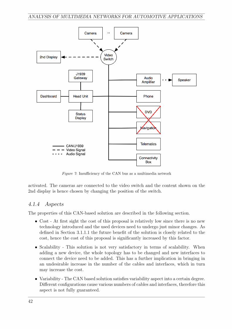
ANALYSIS OF MULTIMEDIA NETWORKS FOR AUTOMOTIVE APPLICATIONS
Figure 7: Insufficiency of the CAN bus as a multimedia network
activated. The cameras are connected to the video switch and the content shown on the2nd display is hence chosen by changing the position of the switch.
4.1.4 Aspects
The properties of this CAN-based solution are described in the following section.
• Cost - At first sight the cost of this proposal is relatively low since there is no newtechnology introduced and the used devices need to undergo just minor changes. Asdefined in Section 3.1.1.1 the future benefit of the solution is closely related to thecost, hence the cost of this proposal is significantly increased by this factor.
• Scalability - This solution is not very satisfactory in terms of scalability. Whenadding a new device, the whole topology has to be changed and new interfaces toconnect the device need to be added. This has a further implication in bringing inan undesirable increase in the number of the cables and interfaces, which in turnmay increase the cost.
• Variability - The CAN based solution satisfies variability aspect into a certain degree.Different configurations cause various numbers of cables and interfaces, therefore thisaspect is not fully guaranteed.
42
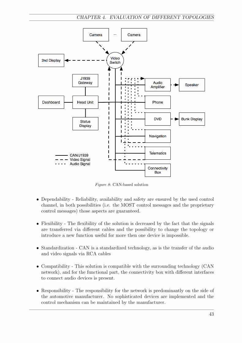
CHAPTER 4. EVALUATION OF DIFFERENT TOPOLOGIES
Figure 8: CAN-based solution
• Dependability - Reliability, availability and safety are ensured by the used controlchannel, in both possibilities (i.e. the MOST control messages and the proprietarycontrol messages) those aspects are guaranteed.
• Flexibility - The flexibility of the solution is decreased by the fact that the signalsare transferred via different cables and the possibility to change the topology orintroduce a new function useful for more then one device is impossible.
• Standardization - CAN is a standardized technology, as is the transfer of the audioand video signals via RCA cables
• Compatibility - This solution is compatible with the surrounding technology (CANnetwork), and for the functional part, the connectivity box with different interfacesto connect audio devices is present.
• Responsibility - The responsibility for the network is predominantly on the side ofthe automotive manufacturer. No sophisticated devices are implemented and thecontrol mechanism can be maintained by the manufacturer.
43
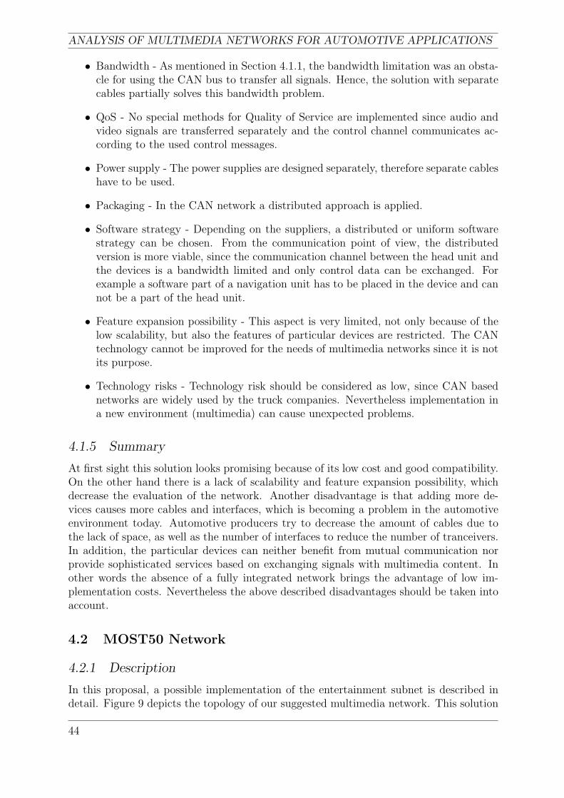
ANALYSIS OF MULTIMEDIA NETWORKS FOR AUTOMOTIVE APPLICATIONS
• Bandwidth - As mentioned in Section 4.1.1, the bandwidth limitation was an obsta-cle for using the CAN bus to transfer all signals. Hence, the solution with separatecables partially solves this bandwidth problem.
• QoS - No special methods for Quality of Service are implemented since audio andvideo signals are transferred separately and the control channel communicates ac-cording to the used control messages.
• Power supply - The power supplies are designed separately, therefore separate cableshave to be used.
• Packaging - In the CAN network a distributed approach is applied.
• Software strategy - Depending on the suppliers, a distributed or uniform softwarestrategy can be chosen. From the communication point of view, the distributedversion is more viable, since the communication channel between the head unit andthe devices is a bandwidth limited and only control data can be exchanged. Forexample a software part of a navigation unit has to be placed in the device and cannot be a part of the head unit.
• Feature expansion possibility - This aspect is very limited, not only because of thelow scalability, but also the features of particular devices are restricted. The CANtechnology cannot be improved for the needs of multimedia networks since it is notits purpose.
• Technology risks - Technology risk should be considered as low, since CAN basednetworks are widely used by the truck companies. Nevertheless implementation ina new environment (multimedia) can cause unexpected problems.
4.1.5 Summary
At first sight this solution looks promising because of its low cost and good compatibility.On the other hand there is a lack of scalability and feature expansion possibility, whichdecrease the evaluation of the network. Another disadvantage is that adding more de-vices causes more cables and interfaces, which is becoming a problem in the automotiveenvironment today. Automotive producers try to decrease the amount of cables due tothe lack of space, as well as the number of interfaces to reduce the number of tranceivers.In addition, the particular devices can neither benefit from mutual communication norprovide sophisticated services based on exchanging signals with multimedia content. Inother words the absence of a fully integrated network brings the advantage of low im-plementation costs. Nevertheless the above described disadvantages should be taken intoaccount.
4.2 MOST50 Network
4.2.1 Description
In this proposal, a possible implementation of the entertainment subnet is described indetail. Figure 9 depicts the topology of our suggested multimedia network. This solution
44
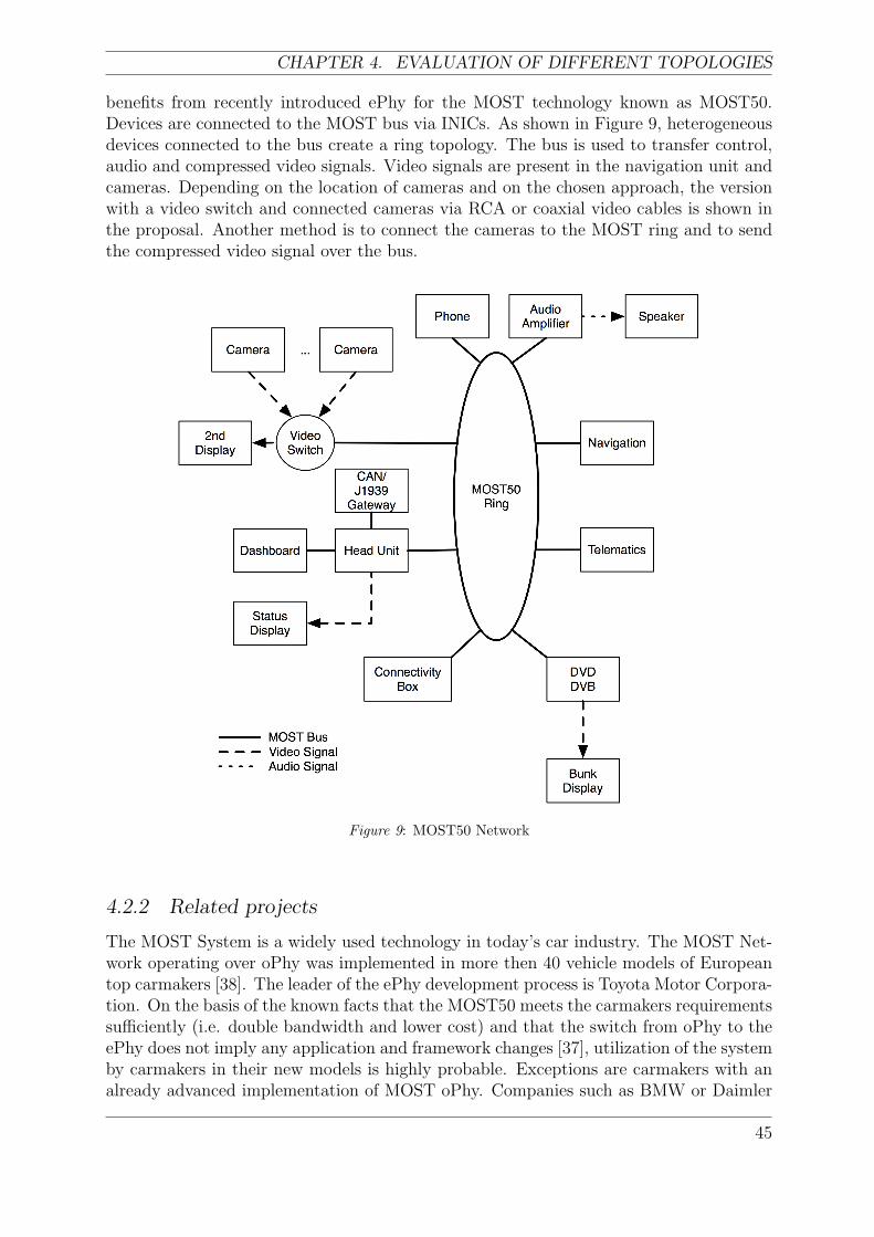
CHAPTER 4. EVALUATION OF DIFFERENT TOPOLOGIES
benefits from recently introduced ePhy for the MOST technology known as MOST50.Devices are connected to the MOST bus via INICs. As shown in Figure 9, heterogeneousdevices connected to the bus create a ring topology. The bus is used to transfer control,audio and compressed video signals. Video signals are present in the navigation unit andcameras. Depending on the location of cameras and on the chosen approach, the versionwith a video switch and connected cameras via RCA or coaxial video cables is shown inthe proposal. Another method is to connect the cameras to the MOST ring and to sendthe compressed video signal over the bus.
Figure 9: MOST50 Network
4.2.2 Related projects
The MOST System is a widely used technology in today’s car industry. The MOST Net-work operating over oPhy was implemented in more then 40 vehicle models of Europeantop carmakers [38]. The leader of the ePhy development process is Toyota Motor Corpora-tion. On the basis of the known facts that the MOST50 meets the carmakers requirementssufficiently (i.e. double bandwidth and lower cost) and that the switch from oPhy to theePhy does not imply any application and framework changes [37], utilization of the systemby carmakers in their new models is highly probable. Exceptions are carmakers with analready advanced implementation of MOST oPhy. Companies such as BMW or Daimler
45
ANALYSIS OF MULTIMEDIA NETWORKS FOR AUTOMOTIVE APPLICATIONS
Chrysler do not want to lose their lead in the optical field area investigation and willprobably continue to support further MOST oPhy versions such as MOST150.
4.2.3 Communication
In order to explain the communication process on the application layer, a more detailedexample will be introduced and described. To keep the complexity of the example on anunderstandable level, let us consider the simple case from Figure 10 with audio, phoneand HMI devices connected to the MOST50 bus. According to the MOST terminology,the FBlocks amplifier and GSM mobile unit are called slaves and FBlock HMI is labeledas a controller. The messages sent though the control channel are denoted as protocols.The communication example is shown in Figure 10.Example: An audio device contains several more function blocks i.e. CD player, ampli-fier and radio tuner. After the change of the CD track, an incoming phone call will occurand the sound signal will be changed.
Figure 10: MOST Example
Solution: The HMI controls the audio device via the FBlock CD shadow located in thecontroller. As mentioned in the chapter 2.1, the shadow in the controller represents animage of the property of the slave device. The next track on the CD can be chosen bypressing the NEXT button, where the shadow of the CD will transfer the following pro-tocol from the HMI device (controller) to the amplifier (slave): CD.1.Track.Set(2). Onthe application layer the physical addresses are not known, hence the Network services ofHMI assigns to this protocol the device ID parameter as follows:
Audio.CD.1.Track.Set(2)
and for the transmission the structure is completed by a sender’s address:HMI.Audio.CD.1.Track.Set(2). This telegram is received by the audio device as aHMI.CD.1.Track.Set(2), where the parameter device ID=Audio is missing, since thereis no need to have this information on Audio’s application level.Following the same procedure, a status reply can be sent:
Audio.HMI.CD.1.Track.Status(2),
46
CHAPTER 4. EVALUATION OF DIFFERENT TOPOLOGIES
similarly interpreted by the controller as: Audio.CD.1.Track.Status(2). The contentof the status message can be displayed on the monochrome Status Display (SD) . Untilthis point we do not have any synchronous or asynchronous channels allocated on theMOST bus. The only used communication channel is the control channel, because theamplifier and the speakers are integrated, connected to the audio device respectively.Let us assume that the integrated GSM mobile unit is receiving a call. Thus after thereception of the call the synchronous channel has to be allocated. Firstly the user has todecide if the call will be accepted or rejected. The phone number can be displayed on theSD via this telegram:
GSM.HMI.1.Call.Status(PhoneNumber)
(where Call is an event) from the GMS unit to the HMI device.Simultaneously, the properties Audio.HMI.CD.1.Stop.Set() in the CD andAudio.HMI.Amplifier.1.Ring.set() in the amplifier are started. The ring tone canbe integrated as e.g. a generated sound from a synthesizer in the amplifier, a saved ringtone in the HMI/Amplifier or a different solution for the integrated phone module. Inthe case that the call is received, a method inCall.StartResult provided in the FBlockGSM is triggered, otherwise when the call is not accepted the method inCall.Abort isstarted. Method inCall.StartResult will act as an initiator for establishing a connectionbetween the source and the sink. The Connection Manager (CM) is responsible for allsynchronous connections. The procedure for establishing a connection is:
1. Firstly, the initiator (inCall) starts a method BuildSyncConnection in the CM.
2. The Connection Manager will establish and maintain the synchronous channel be-tween the source (GSM unit) and the sink (Audio device), hence it will send acommand to the source to connect its output to the synchronous network channel.In our case, the source unit does not need to allocate the channel but uses the pro-posed one from CM instead. After this, the source unit sends a status reply to theCM.
3. If the status is ‘connected’, the CM is trying to connect the sink to the same chan-nel. After sending the description of the channel (delay and number), the sink isconnected and a status reply is sent back. When the sink (i.e. the amplifier) isconnected, the ring signal will be cancelled and the GSM sound signal can proceedto the speakers.
4. When both the source and the sink are connected to the channel, the connectionis established and the report to the initiator (GSM unit) is sent. CM stores theconnection data in case that a new sink wants to connect to the source.
Now the telegram inCall.Result from the GSM unit to the HMI unit can be sent. Letus assume that one FBlock in the GSM unit is a microphone connected to the GSM voicecoder. The GSM call is finally established through the MOST Network.
4.2.4 Aspects
In this section our solution is analyzed with regard to the aspects described in the thirdpart of the thesis.
47
ANALYSIS OF MULTIMEDIA NETWORKS FOR AUTOMOTIVE APPLICATIONS
• Cost - In order to analyze the cost of our system, a trade off between the cost relatedto the introduction of a new technology and the future sufficiency of the networkhas to be selected. On one hand we have the expenses for the implementation ofnew protocol: particular devices need to be equipped with INIC for MOST50 andnew interfaces to connect the devices, NetServices functions and application layerhave to be defined. On the other hand the future utilization of the network shouldbe considered carefully (i.e. how long will the network be sufficient for the newdevices and technologies?).
• Scalability - Our proposal is designed as a fully scalable system. Firstly, the MOSTbus can operate with 64 INICs, hence we can connect up to 64 heterogeneous devicesto the network.
• Variability - Different combinations of multimedia devices are supported. The pro-posed network can be implemented from the simplest case, consisting of one audiodevice and integrated phone unit, to complex combinations of multimedia devices(see Figure 9).
• Dependability - Reliability, availability and safety are ensured by the properties ofthe MOST technology. The error detection and the phase lock loop mechanisms areproviding reliable services. Maintainability is ensured in the system (i.e. furtherrepairs, changes and improvements in terms of maintainability are available).
• Flexibility - Flexibility is ensured by the MOST Technology. Different topologiesare possible and different physical layers for the MOST Technology are available.The change of the physical layer does not affect the higher layers.
• Standardization - MOST System is a standardized network. Major automotivecarmakers, which are members of MOSTCO, are continuously developing and im-proving the system.
• Compatibility - Compatibility is guaranteed by a gateway to the CAN-based networkand with the connectivity box.
• Responsibility - Since the MOST System is an open standard, the implementa-tion can be accomplished by automotive producers in conjunction with appropriatevendors. Thus the responsibility results from this cooperation.
• Bandwidth - Particular devices can use a bandwidth up to 50 Mbit/s. For calcu-lating the amount of bandwidth, we have to consider the audio and video signalseparately. The most bandwidth consuming audio device in our network is a DVDplayer using an AC3 codec, with a data rate of 448 kbit/s, also known as a DolbyDigital. Enhanced AC3 codec in Digital TV has improved coding efficiency and thebandwidth needed is about 256 kbit/s. Video signals can be transferred over theMOST Network in a compressed format. From Figure 9 follows, that the only videosignal transferred over the network is the navigation video signal. This signal has tobe compressed and the bandwidth needed depends on the implemented navigationdevice.
• QoS - The introduced priority levels increase the probability that the importantmessages will be sent, e.g. when the control channel is overloaded.
48
CHAPTER 4. EVALUATION OF DIFFERENT TOPOLOGIES
• Power Supply - The power supplies in our proposal have to be separate from theINICs, micro-controller and application peripherals, therefore separate cables forpower supplies is needed.
• Packaging - The proposed solution is organized in a distributed manner (devicescommunicating over a shared bus). Theoretically any device in the MOST networkcan be a timing master, but in our case the HMI is logically chosen as a controlunit.
• Software strategy - Depending on the approach of carmakers, different strategies canbe used. The navigation device can e.g. only send GPS position data to the HMI,where implemented software will draw the position as a picture. Another solutionwould be to have the software part in the Navigation GPS unit and send the dataover the network in a viewable form (shown on the 2nd display).
• Feature expansion possibility - The extensive research process in MOST technologyis giving us a certainty of further development of the system. Another fact is thatthe MOST Technology does not necessitate changes in the higher layers when thesystem is upgraded (e.g. the differences between MOST25 and MOST50 are onlyin the NIC).
• Technology risks - With the introduction of a new technology there is certainly arisk present, even though the MOST Network is a standard.
4.2.5 Summary
MOST Technology is a dynamically developing area. In this part, the description, relatedprojects, a communication example and aspects evaluation of the proposed solution wereinvestigated. Table 5 shows how the particular aspects can be interpreted and how signif-icant they are for this proposed solution. The importance of scalability and cost shouldbe taken into account. The MOST50 proposal appears to be a promising solution forautomotive multimedia networks. An example from the Section 4.2.3 is described withMSC in Appendix A.
4.3 Network based on IDB-1394
4.3.1 Description
Although most car manufacturers focus on MOST as the favorite network, a great deal ofresearch on how to implement a IDB-1394-based network has been done. The approacheswere in most cases academic ones. As mentioned earlier, companies, such as Renault orNissan have already implemented an advanced prototype of an IDB-1394-based network.A similar topology as it was used in those projects has been taken as a basis and wasextended by additional devices which may be required for the truck sector. This topologyis shown in Figure 11. The most bandwidth consuming devices are the cameras and theentertainment sources. As DVD and DVB are assumed to be available only during restperiods, their impact on the bandwidth is moderate. The proposed topology includes onthe other hand a large number of cameras which send video data all the time. Therefore
49
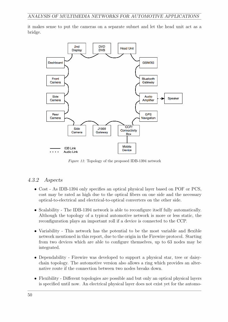
ANALYSIS OF MULTIMEDIA NETWORKS FOR AUTOMOTIVE APPLICATIONS
it makes sense to put the cameras on a separate subnet and let the head unit act as abridge.
Figure 11: Topology of the proposed IDB-1394 network
4.3.2 Aspects
• Cost - As IDB-1394 only specifies an optical physical layer based on POF or PCS,cost may be rated as high due to the optical fibers on one side and the necessaryoptical-to-electrical and electrical-to-optical converters on the other side.
• Scalability - The IDB-1394 network is able to reconfigure itself fully automatically.Although the topology of a typical automotive network is more or less static, thereconfiguration plays an important roll if a device is connected to the CCP.
• Variability - This network has the potential to be the most variable and flexiblenetwork mentioned in this report, due to the origin in the Firewire protocol. Startingfrom two devices which are able to configure themselves, up to 63 nodes may beintegrated.
• Dependability - Firewire was developed to support a physical star, tree or daisy-chain topology. The automotive version also allows a ring which provides an alter-native route if the connection between two nodes breaks down.
• Flexibility - Different topologies are possible and but only an optical physical layersis specified until now. An electrical physical layer does not exist yet for the automo-
50
CHAPTER 4. EVALUATION OF DIFFERENT TOPOLOGIES
tive environment, but if it will be included in the future, the change of the physicallayer does not affect the higher layers.
• Standardization - IDB-1394 is fully standardized by the IDB forum as well as AMI-C.
• Compatibility - IDB-1394 is completely compatible with IEEE-1394-based consumerelectronics as most protocol layers are equal. Furthermore gateways to Bluetoothand CAN are available.
• Responsibility - IDB-1394 is standardized, so the implementation can be accom-plished by automotive producers in conjunction with appropriate vendors. Thusthe responsibility results from this cooperation.
• Bandwidth - Compared to MOST, the bandwidth is much higher. As long as com-pressed video is used, there will be no limitation. On the other hand when uncom-pressed data is needed, for instance because only minimum delay can be accepted,the available 400 Mbit/s may be the bottleneck depending on resolution, colour-depth and frames per second.
• QoS - IDB-1394 supports both asynchronous and isochronous traffic and providesmechanisms for QoS as mentioned earlier.
• Power Supply - Traditional IEEE-1394 is able to supply power to the devices usingsome of the copper wires. As the automotive version is only specified for opticalfibers, extra wiring is needed.
• Technology risks - As can be seen in the related projects section, there has been agreat deal of research done using this type of network, but most car manufacturersstill focus on the MOST solution. Therefore it is hard to say, how the support forthis technology will be in the future. Also, the latest update of the official IDBwebsite dates back a rather long time.
4.3.3 Summary
A major benefit of the IDB-1394-based network is the dynamic reconfiguration afterbooting and after changes in the topology, such as connecting a portable device to theconsumer convenience port. If different encoding is used, as mentioned in the Nissanproject in the related work section, IDB-1394 is even suitable for camera applicationswhere only a minimum delay can be accepted. The drawback nevertheless is that currentlyonly optical fibers are specified for automotive applications which makes it interesting forconsumer cars, but not for trucks, due to the rather high costs of fibers and converters.
4.4 Network using the APIX link
4.4.1 Description
Figure 12 shows a proposed topology based on the APIX link. A similar network for theentertainment system in a car is shown in [15] and [16]. The network consists of the head
51
ANALYSIS OF MULTIMEDIA NETWORKS FOR AUTOMOTIVE APPLICATIONS
unit, which contains most of the intelligence, two or more displays, some cameras locatedaround the vehicle and gateways to the J1939 vehicle bus, GPS and a GSM unit.
All cameras are assumed to have a resolution of 640-by-480 pixels operating at 60 framesper second. If the cameras have a color resolution of 16 bits, or 10 bits for the night visioncamera respectively, the bandwidth of the APIX link will be sufficient to transmit themultiplexed uncompressed signal.
Bitrate =∑
sources
resolution · colordepth · frames per second
On the other hand, there is no bandwidth problem with the two rear view cameras andthe other sources such as the DVD player or the DVB receiver. The two camera signalscan even have a colour resolution of 24 bits and the data rate of the multiplexed signalis still below 1 Gbit/s. As DVD and DVB are not available during driving, those sourcesare connected via a video switch and therefore they have no impact on the bandwidthcalculation. One advantage of this link is that the cameras can be supplied with powerover the return channel, due to the fact that both the uplink and the downlink channelare completely decoupled from direct voltage. Therefore there is only need for one STPcable to connect the camera and the head unit.
As the side-band channels can be used to control the cameras in real-time by trans-mitting the I2C as well as the CAN bus, it is also possible to synchronize them in orderto get a 360-degree-view or a multiview system.
4.4.2 Communication
Front camera system: The front and side cameras send uncompressed video via amultiplexer to the CPU in the head unit. In the CPU of the head unit all the neces-sary image processing is done, required for the lane departure warning system, objectrecognition and similar tasks.
Rear view cameras and entertainment sources: As the DVD, DVB and otherentertainment functions are not provided during driving, a video switch is suggested toswitch video between the rear view system in normal operation and DVD/DVB duringthe rest periods.
Displays: As mentioned before, the displays receive uncompressed pixeldata from thehead unit. To input data, such as messages from the driver to the dispatcher, touchscreencan be used. The emerging control data can be transmitted either by sending I2C signals,by using modified CAN/J1939 frames or even by using the messages of the MOST controlchannel on the side-band channels.
GPS and Navigation: The communication between the head unit and the navigationsystem works the same way as from the head unit to the displays. The position is trans-mitted over the side-band channel and the according images, if not created in the headunit, will use the high-bandwidth link.
52
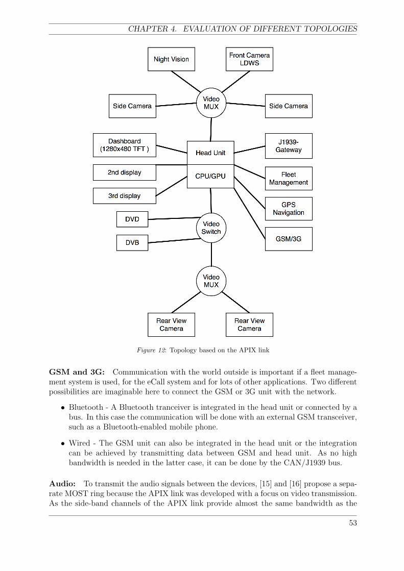
CHAPTER 4. EVALUATION OF DIFFERENT TOPOLOGIES
Figure 12: Topology based on the APIX link
GSM and 3G: Communication with the world outside is important if a fleet manage-ment system is used, for the eCall system and for lots of other applications. Two differentpossibilities are imaginable here to connect the GSM or 3G unit with the network.
• Bluetooth - A Bluetooth tranceiver is integrated in the head unit or connected by abus. In this case the communication will be done with an external GSM transceiver,such as a Bluetooth-enabled mobile phone.
• Wired - The GSM unit can also be integrated in the head unit or the integrationcan be achieved by transmitting data between GSM and head unit. As no highbandwidth is needed in the latter case, it can be done by the CAN/J1939 bus.
Audio: To transmit the audio signals between the devices, [15] and [16] propose a sepa-rate MOST ring because the APIX link was developed with a focus on video transmission.As the side-band channels of the APIX link provide almost the same bandwidth as the
53
ANALYSIS OF MULTIMEDIA NETWORKS FOR AUTOMOTIVE APPLICATIONS
traditional MOST25 network it is also imaginable that sound could be sent over thosechannels. Further investigations can be done in this case.
4.4.3 Aspects
The following describes how the solution based on the APIX link performs in relation tothe previously defined aspects.
• Cost - The use of shielded twisted pair cables instead of optical fibers keeps the costof the solution low. On the other hand rather high development costs may arise asthere is no real reference implementation available yet.
• Scalability - The Apix link is a point-to-point pixel link. Therefore the main lim-itations for the scalability are located in the head unit. The more connectors andthe faster the CPU or GPU is, the more devices can be connected.
• Variability - This link only makes sense if high-quality video is required. But thendifferent scenarios are possible, starting from a simple rear-view camera to a fullyequipped network as proposed above.
• Dependability - As the apix link is a point-to-point link with no redundancy, soif a single link is interrupted, there is no alternative route, where the data can betransmitted.
• Flexibility - The GBit/s downstream link is a direct pixel link, but the side-bandchannels make APIX very flexible, as a variety of buses and protocols can be sentover those channels.
• Standardization - The APIX chip is solely developed and produced by Inova Semi-conductors. A data sheet is available for download, but APIX is not standardized.On the other hand, a separate standardized MOST ring to transmit audio signalsis suggested by Inova Semiconductors.
• Compatibility - The chip connects to common 10-, 12-, 18- and 24-bit RGB in-terfaces. Furthermore, the side-band channels can transmit the popular I2C busbi-directionally to control camera functions.
• Responsibility - Only a preliminary data sheet is available now. Inova provides thechip itself. First cars using this link should be released in 2008. Therefore it is verylikely, that suppliers will offer devices, already including an APIX link, soon.
• Bandwidth - Besides IDB-1394 (under certain conditions), this link is the onlypossibility in the automotive area to transmit uncompressed, low-delay video signals.Furthermore it is the only solution presented in this report which provides enoughbandwidth for future high-resolution 1280-by-480 pixel TFTs which will probablyreplace the traditional analogue gauges.
• QoS - The control messages on the side-band channels do not influence the actualpixel data in any way. Consequently full QoS is given concerning the link itself.
54
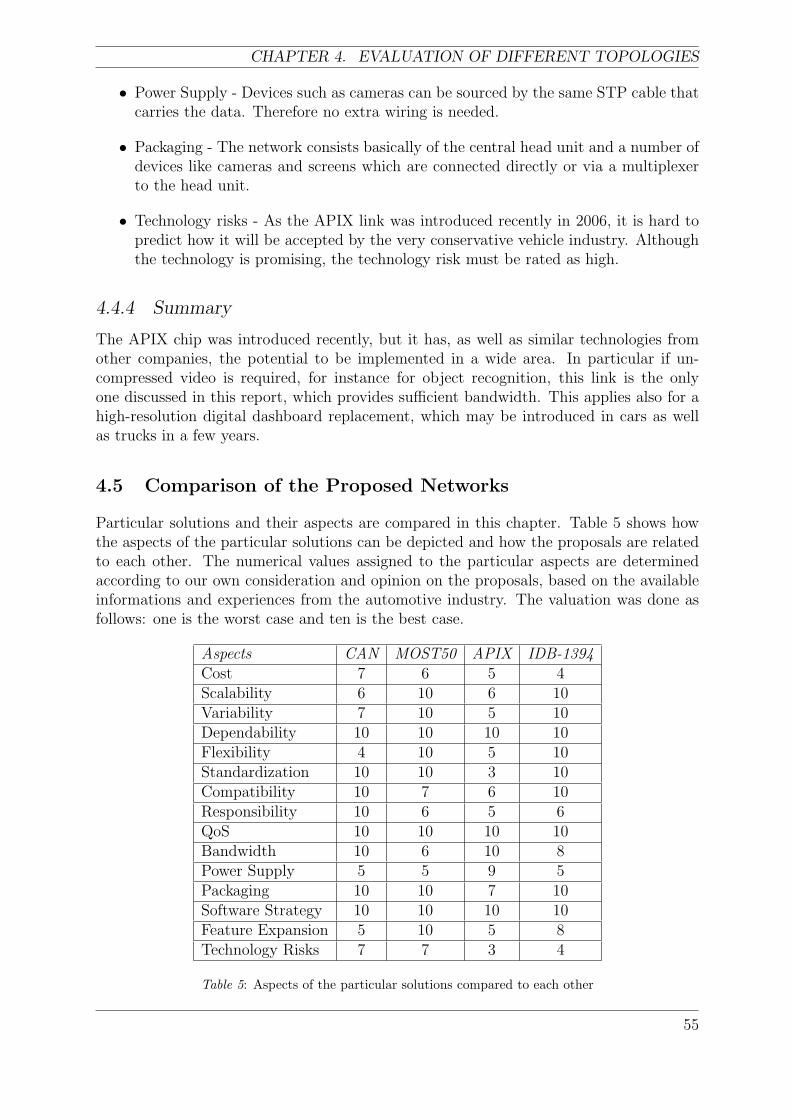
CHAPTER 4. EVALUATION OF DIFFERENT TOPOLOGIES
• Power Supply - Devices such as cameras can be sourced by the same STP cable thatcarries the data. Therefore no extra wiring is needed.
• Packaging - The network consists basically of the central head unit and a number ofdevices like cameras and screens which are connected directly or via a multiplexerto the head unit.
• Technology risks - As the APIX link was introduced recently in 2006, it is hard topredict how it will be accepted by the very conservative vehicle industry. Althoughthe technology is promising, the technology risk must be rated as high.
4.4.4 Summary
The APIX chip was introduced recently, but it has, as well as similar technologies fromother companies, the potential to be implemented in a wide area. In particular if un-compressed video is required, for instance for object recognition, this link is the onlyone discussed in this report, which provides sufficient bandwidth. This applies also for ahigh-resolution digital dashboard replacement, which may be introduced in cars as wellas trucks in a few years.
4.5 Comparison of the Proposed Networks
Particular solutions and their aspects are compared in this chapter. Table 5 shows howthe aspects of the particular solutions can be depicted and how the proposals are relatedto each other. The numerical values assigned to the particular aspects are determinedaccording to our own consideration and opinion on the proposals, based on the availableinformations and experiences from the automotive industry. The valuation was done asfollows: one is the worst case and ten is the best case.
Aspects CAN MOST50 APIX IDB-1394Cost 7 6 5 4Scalability 6 10 6 10Variability 7 10 5 10Dependability 10 10 10 10Flexibility 4 10 5 10Standardization 10 10 3 10Compatibility 10 7 6 10Responsibility 10 6 5 6QoS 10 10 10 10Bandwidth 10 6 10 8Power Supply 5 5 9 5Packaging 10 10 7 10Software Strategy 10 10 10 10Feature Expansion 5 10 5 8Technology Risks 7 7 3 4
Table 5: Aspects of the particular solutions compared to each other
55
ANALYSIS OF MULTIMEDIA NETWORKS FOR AUTOMOTIVE APPLICATIONS
A suitable solution can be found when particular requirements are defined and whenthe priorities of all aspects are well known. By using Table 5 the decision can be done andthe solution can be chosen. Generally, a universal solution is impossible to define, sinceall of the solutions have their own advantages and disadvantages and, before the decisionprocess, the requirements have to be defined.
By comparing the particular networks we can observe the following relations. The cheap-est solution is the CAN Network, but as it was stated it suffers from insufficiency inscalability, flexibility and feature expansion possibility. The IDB-1394 network has a rel-atively high ranking in most of the aspects except the cost, which is caused by the opticalphysical layer. As visible from Table 5 such an expensive solution should still be evaluatedsince it fulfills the other requirements and brings other benefits (e.g. future utilization ofthe system). The APIX link is a promising solution for the transmission of video signals.Another important aspect is scalability, where MOST and IDB1394 networks reach themaximum value. Aspects like dependability and software strategy are not dependent onlyon the used technology but also on the agreement between suppliers and automotive pro-ducers. Feature expansion possibility is an important property of the system and is fullysatisfied by the MOST and IDB1394 technologies. Standardization is fulfilled by CAN,MOST and IDB1394.
From our point of view the MOST Network for audio signals and the APIX link as amedium for the transfer of video signals appear to be as the most suitable solution.
4.6 Conclusions
Multimedia networks for automotive applications is an evolving and promising area. Re-searchers from different communities (such as IT, Communication and Electronic, etc.)are focused on the automotive industry, in order to migrate their high-end products intovehicles. This requires a different approach to the environment and conditions, which aretypical in the automotive area. Besides this, the customers demand more sophisticatedfunctions to be implemented in their vehicles. The car industry is the main driver forautomotive multimedia networks and during our investigation the car industry was ourmain source of information about the automotive multimedia networks. Since this thesisis concerned with the truck industry, its specific features were taken into account duringour work. It should be noted that the truck industry suffers from a lack of available in-formation compared to the car industry. In spite of this, a lot of similarities can be derived.
This thesis analyzes multimedia networks for automotive applications. The first part,the introduction and related projects, introduces the area of investigation. In the secondpart, an extensive survey of the state of art is given. The available communication proto-cols and technologies are described in detail. It should be remarked, that the developmentprocess is relatively young and the effort to standardize and propagate particular technolo-gies is visible. The third part describes the requirements on the automotive electronicsin general and requirements driven by infotainment systems. From the description of theaspects an outlook on the environment where the final proposals should be implementedis given. Finally, the last part represents the main part of our thesis. By comparing theavailable protocols and networks with our investigated aspects, four possible solutions are
56
described and examined. The chosen topologies result from the network specificationsand their implementation in the automotive industry.
The MOST Network is considered as a standardized and promising technology, but thisdoes not mean that the importance of other protocols and networks should be decreased.CAN-based solutions cannot support the development process for long and will not provesatisfactory for the future devices due to the limited scalability and feature expansionpossibility. New networks and technologies supporting more bandwidth for video signalsare going to be introduced in the future, but before this, an APIX solution for videosignals together with the MOST audio network appear to be, from our point of view,the most suitable solution. An example of how optical fibers can be used in the truckindustry is given by the IDB-1394 Network. Generally, optical fibers are not popularamong truck manufacturers. Therefore the implementation is not very probable. Thismight be a disadvantages for future technologies. When for example the bandwidth ofcopper cables will not be sufficient anymore, then optic fibers will be introduced. Thedisadvantage is the introduction of optic fibers as a new technology into already existingnetworks without any previous experiences and implementations. On the other hand,there is a huge development process behind electrical cables and the methods of how toimplement them in the automotive industry are well known.
Our aim has been to define the problems and aspects for choosing an automotive multime-dia network. Our suggestions for the decision process are correlated to the requirementsof the automotive manufacturer. In other words, they depend on what the manufacturerwants to implement. Automotive producer’s requirements are represented as the partic-ular aspects. From Table 5 the solution can be chosen. Generally, a solution which fullysatisfies all of the requirements does not exist and therefore a suitable trade off has tobe chosen. A reasonable approach, when the network should be selected , is to considerthe network usage from a future point of view and to take into account all automotivemultimedia protocols and networks available on the market, even newly arising promisingtechnologies.

CHAPTER 4. EVALUATION OF DIFFERENT TOPOLOGIES
Bibliography
[1] Kvaser AB. SAE J1939. http://www.kvaser.com/can/hlps/j1939.htm, 2005.
[2] K. Chaaban, M. Shawky, and P. Crubille. Dynamic Reconfiguration for high level In-vehicle application using IEEE-1394. 2004 IEEE Intelligent Transportation SystemsConference, pages 826–830, October 2004.
[3] K. Chaaban, M. Shawky, and P. Crubille. A Distributed Framework For Real-TimeIn-Vehicle Applications. Proceeding of the 8th International IEEE Conference onIntelligent Transportation Systems, pages 925–929, September 2005.
[4] MOST Cooperation. MOST FunctionBlock AudioAmplifier, Rev. 2.4.2. http:
//www.mostcooperation.com/downloads/Specifications/MOST%20Function%
20Block%20Library/MOST%20FunctionBlock%20AudioAmplifier.pdf, September2003.
[5] MOST Cooperation. MOST FunctionBlock AudioDiskPlayer, Rev. 2.4. http:
//www.mostcooperation.com/downloads/Specifications/MOST%20Function%
20Block%20Library/MOST%20FunctionBlock%20AudioDiskPlayer.pdf, September2003.
[6] MOST Cooperation. MOST MSC Cookbook. http://mostcooperation.com/
downloads/Specifications/MOST%20Guidelines/MOST%20MSC%20Cookbook.pdf,April 2005.
[7] MOST Cooperation. MOST Specification Rev 2.4. http://www.mostcooperation.com, 2005.
[8] MOST Cooperation. Japan Interconnectivity Conference. http://www.
mostcooperation.com/news/Conferences+%26+Presentations/2006/1/40/
files/01MOSTCO+Presentation+2006.pdf, November 2006.
[9] MOST Cooperation. MOST Specification Rev 2.5. http://www.mostcooperation.com, 2006.
[10] Dick Davis. Simple Lightweight Devices Cut Cost by Taking Direction from a Full-featured Controller node. http://www.1394ta.org/Press/2006Press/june/6.20.a.htm, June 2006.
[11] EU. Cars that can dial 112: Commission an industry target 2009.http://europa.eu/rapid/pressReleasesAction.do?reference=IP/05/
134&format=HTML&aged=0&language=en&guiLanguage=en, February 2005.
[12] Christian Hess, Jurgen Baumgartner, and Matthias Karcher. Einfacher Umstiegauf MOST50. http://www.hanser-automotive.de/fileadmin/heftarchiv/2004/11993.pdf, 2006.
59
[13] ITU. ITU-T Recommendation Z.120 Message Sequence Chart. http://www.itu.
int/ITU-T/studygroups/com10/languages/Z.120 1199.pdf, November 1999.
[14] Venkatraman K K. Real Time Image Transfer over WLAN for Rear View Systemsin Automobiles. WIPRO Technologies White Paper, pages 1–9, 2003.
[15] Robert Kraus. Datenautobahn fur Multimedia auf vier Radern. http://www.
electroniknet.de/index.php?id=1373, 2006.
[16] Axel Krepil. Datenautobahn fur ungestorte Bildubertragung. http://www.
hanser-automotive.de/fileadmin/heftarchiv/2004/11995.pdf, 2006.
[17] Axel Krepil. Kfz-Elektronik: Videodatenautobahn ubertragt bis zu 1 GBit/s. http://www.elektronikpraxis.de/fachartikel/ep fachartikel 2951471.html, 2006.
[18] Ola Larses. Architecting and modeling automotive embedded systems. PhD thesis,Kungliga Tekniska Hogskolan, Stockholm, December 2005.
[19] M. Lessard. IDB-1394 Automotive Reference Platform - Enabling In-vehicle Enter-tainment. http://www.touchbriefings.com/pdf/11/auto031 t Mindre∼1.pdf,2003.
[20] D. McClure. White Paper: Trends of in-car Bluetooth and wireless technologiesin Europe. http://www.abd.co.uk/assets/770 Bluetooth whitepaper.pdf, July2005.
[21] Keiko Murase. EMC control with High-speed differential transmission withcommon mode filter. http://www.mostcooperation.com/news/Conferences+
%26+Presentations/2006/1/40/files/05+TDK+Presentation+2006.pdf, Novem-ber 2006.
[22] H. Muyshondt. MOST Intelligent network interface controllers. http://www.
esemagazine.com/index.php?option=com content&task=view&id=84&Itemid=2,February 2006.
[23] Akio Nezu and Wolfgang Wiewesiek. Networking standards enable in-vehicle video entertainment and information systems. http://www.
automotivedesignline.com/howto/infotainment/192300781;jsessionid=
CYHM022NAXR0KQSNDLOSKHSCJUNN2JVN, 2006.
[24] A. Paskins. The IEEE 1394 Bus. IEE Colloquium on New High Capacity DigitalMedia And Their Applications, pages 1–6, 1997.
[25] M. Rabel, A. Schmeiser, and H.-P. Großmann. Integrating IEEE 1394 as InfotainmentBackbone into the Automotive environment. IEEE Trans. Veh. Technol., 3:2026–2031, 2001.
[26] M. Rabel, A. Schmeiser, and H.-P. Großmann. Ad-hoc In-car Networking Concept.In Proceeding of the 8th International IEEE Conference on Intelligent TransportSystems, pages 143–148, Vienna, Austria, September 2005.
[27] Robert Reiter. MOST at BMW Group - Experience and future scenar-ios. http://www.mostcooperation.com/news/Conferences+%26+Presentations/
2006/1/40/files/10+BMW+Presentation+2006.pdf, November 2006.
[28] SAE. J1939-15 - Network Layer, 1997.
[29] SAE. J1939-11 - Physical Layer, 250 kbit/s, Twisted Shilded Pair, 1999.
[30] SAE. J1939-15 - Reduced Physical Layer, 250 kbit/s, Unshielded Twisted Pair, 2000.
[31] SAE. J1939-21 - Data Link Layer, 2001.
[32] SAE. J1939-81 - Network Management, 2002.
[33] SAE. J1939-71 - Vehicle Application Layer, 2005.
[34] Inova Semiconductors. APIX Specification Rev 0.9. http://www.
inova-semiconductors.de/en/datasheets/Q PP APIX.pdf, 2006.
[35] SMSC. ePHY Overview and Implementation. http://smsc-ais.com/files/ePHY/ePHY Overview TB0812AN1A1.pdf, 2006.
[36] SMSC. Media Local Bus Specification. http://smsc-ais.com/files/MediaLB
Spec 3v0.pdf, 2006.
[37] SMSC. MOST50 Double Bandwidth and Electrical Physical Layer.http://www.mostcooperation.com/news/Conferences+%26+Presentations/
2006/1/40/files/03+SMSC+Presentation+2006.pdf, November 2006.
[38] SMSC. SMSC’s MOST50 Technology Doubles the Bandwidth for Automotive Mul-timedia Networking and Supports an Electrical Physical layer. http://www.smsc.
com/whatsnew/pr/most50pr.html, June 2006.
[39] D. Steinberg and Y. Birk. An Empirical Analysis of the IEEE-1394 Serial Bus Pro-tocol. IEEE Micro, 20:58–65, 2000.
[40] T. Kibler and S. Poferl and G. Boeck and H.-P. Huber and E. Zeeb. Optical DataBuses for Automotive Applications. J. Lightwave Technol., 22:2184–2199, September2004.
[41] Matthias Weber and Joachim Weisbrod. Requirements Engineering in AutomotiveDevelopmnet: Experiences and Challenges. IEEE Softw., 20:16–24, September 2003.
[42] E. Zeeb. Optical Data Bus Systems in Cars: Current Status and Future Challenges.In Proc. 27th Eur .Conf. on Opt. Comm., volume 1, pages 70–71, Amsterdam, 2001.

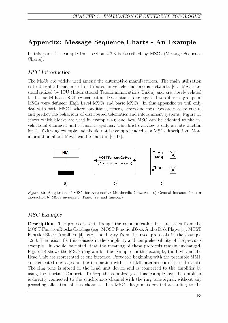
CHAPTER 4. EVALUATION OF DIFFERENT TOPOLOGIES
Appendix: Message Sequence Charts - An Example
In this part the example from section 4.2.3 is described by MSCs (Message SequenceCharts).
MSC Introduction
The MSCs are widely used among the automotive manufacturers. The main utilizationis to describe behaviour of distributed in-vehicle multimedia networks [6]. MSCs arestandardized by ITU (International Telecommunications Union) and are closely relatedto the model based SDL (Specification Description Language). Two different groups ofMSCs were defined: High Level MSCs and basic MSCs. In this appendix we will onlydeal with basic MSCs, where conditions, timers, errors and messages are used to ensureand predict the behaviour of distributed telematics and infotainment systems. Figure 13shows which blocks are used in example 4.6 and how MSC can be adopted to the in-vehicle infotainment and telematics systems. This brief overview is only an introductionfor the following example and should not be comprehended as a MSCs description. Moreinformation about MSCs can be found in [6, 13].
Figure 13: Adaptation of MSCs for Automotive Multimedia Networks: a) General instance for userinteraction b) MSCs message c) Timer (set and timeout)
MSC Example
Description The protocols sent through the communication bus are taken from theMOST FunctionBlocks Catalogs (e.g. MOST FunctionBlock Audio Disk Player [5], MOSTFunctionBlock Amplifier [4], etc.) and vary from the used protocols in the example4.2.3. The reason for this consists in the simplicity and comprehensibility of the previousexample. It should be noted, that the meaning of these protocols remain unchanged.Figure 14 shows the MSCs diagram for the example. In this example, the HMI and theHead Unit are represented as one instance. Protocols beginning with the preamble MMI,are dedicated messages for the interaction with the HMI interface (update end event).The ring tone is stored in the head unit device and is connected to the amplifier byusing the function Connect. To keep the complexity of this example low, the amplifieris directly connected to the synchronous channel with the ring tone signal, without anypreceding allocation of this channel. The MSCs diagram is created according to the
63
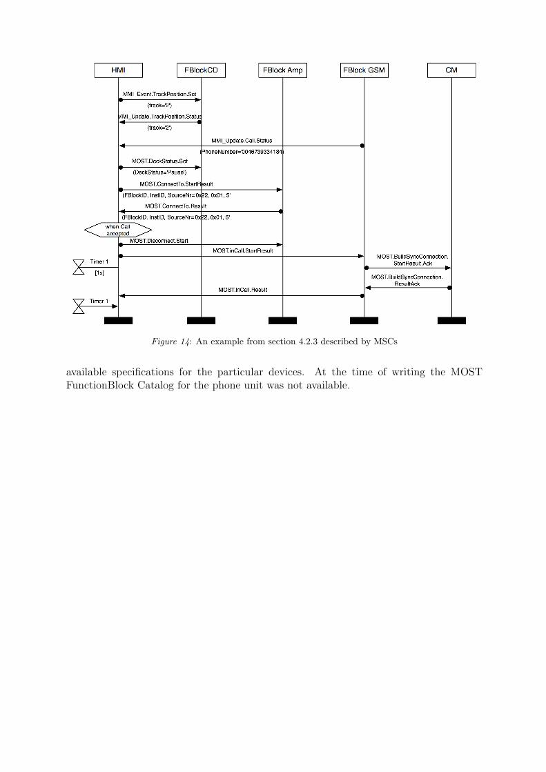
Figure 14: An example from section 4.2.3 described by MSCs
available specifications for the particular devices. At the time of writing the MOSTFunctionBlock Catalog for the phone unit was not available.