Embed Size (px)
Citation preview
Annexure E: TNPA Bed Leveller Replacement: Page 1
ANNEXURE D: SPECIFICATION
Document
Reference
Title No of
pages
This cover page 1
Technical Specification: Bed Leveler 121
Total number of pages 122
Annexure E: TNPA Bed Leveller Replacement: Page 2
ANNEXURE D: SPECIFICATION ............................................................................................. 1
SECTION A - GENERAL DESCRIPTION .................................................................................. 9
A1. GENERAL ........................................................................................................................ 9
A2. DESIGN CRITERIA .........................................................................................................11
A3. TYPE AND FUNCTION ...................................................................................................11
A4. ANTICIPATED MAIN PARTICULARS ............................................................................12
A5. SPEED ............................................................................................................................13
A6. DREDGING PERFORMANCE ........................................................................................13
A7. CLASSIFICATION ...........................................................................................................13
A8. CERTIFICATES ..............................................................................................................14
A9. DRAWINGS AND DOCUMENTATION ............................................................................15
A10. TESTS AND TRIALS .....................................................................................................19
A11. STANDARDIZATION ....................................................................................................22
A12. MAKES .........................................................................................................................22
A13. SPARE PARTS, TOOLS AND INVENTORY .................................................................23
A14. ASSEMBLING, WELDING, ETC. ..................................................................................23
A15. NOISE REDUCING MEASURES ..................................................................................23
SECTION B - STEEL HULL .....................................................................................................25
B1. GENERAL ARRANGEMENT ..........................................................................................25
B2. HULL CONSTRUCTION AND SCANTLINGS .................................................................25
B3. HULL PLATING ...............................................................................................................26
B4. DECKS ...........................................................................................................................26
B5. DOUBLE BOTTOM .........................................................................................................26
B6. STEM AND STERN ........................................................................................................26
B7. DECKHOUSES ...............................................................................................................26
B8. FUNNEL..........................................................................................................................27
B9. PROPELLER SHAFT BRACKETS ..................................................................................27
B10. RUDDERS ....................................................................................................................27
B11. PROPELLER NOZZLES ...............................................................................................28
B12. FENDERING .................................................................................................................28
B13. BUILT-IN TANKS ..........................................................................................................28
B14. VARIOUS SEPARATE TANKS .....................................................................................29
B15. HATCHWAYS ...............................................................................................................29
Annexure E: TNPA Bed Leveller Replacement: Page 3
B16. HAWSE PIPES .............................................................................................................29
B17. CHAIN LOCKERS .........................................................................................................30
B18. STEEL LADDERS AND STAIRWAYS ...........................................................................30
B19. FLOOR PLATES AND GRATINGS IN ENGINE ROOM ................................................30
B20. MANHOLES ..................................................................................................................31
B21. STEEL DOORS .............................................................................................................31
B22. CATWALK .....................................................................................................................31
B23. BULWARKS AND RAILINGS ........................................................................................31
B24. DRAIN PLUGS ..............................................................................................................32
B25. BILGE KEELS ...............................................................................................................32
B26. NAMEPLATES, SHIP'S IDENTIFICATION NUMBER, DRAUGHT MARKS, ETC ..........32
B27. CATHODIC HULL PROTECTION .................................................................................32
B28. PAINTING AND OTHER PROTECTIVE PROCESSES .................................................33
SECTION C - EQUIPMENT ......................................................................................................35
C1. STEERING GEAR ..........................................................................................................35
C2. FORWARD WINDLASSES AND CHAIN STOPPERS .....................................................35
C3. ANCHORS AND CHAIN CABLES ...................................................................................35
C4. BOLLARDS, FAIRLEADS AND MOORING PORTS .......................................................36
C5. HAWSERS AND WIRE ROPES ......................................................................................36
C6. MOTOR RESCUE BOAT ................................................................................................36
C7. MOTOR RESCUE BOAT AND LIFE-RAFT LAUNCHING DAVIT ....................................36
C9. GANGWAY .....................................................................................................................36
C10. MASTS AND RIGGING .................................................................................................37
C11. HOISTING GEAR IN ENGINE ROOM...........................................................................37
C12. STORES HANDLING DAVIT ........................................................................................37
C13. FIXED FIRE-EXTINGUISHING SYSTEMS ...................................................................37
C14. INTEGRATED FIRE DETECTION AND FIRE ALARM SYSTEM AND SMOKE
DETECTION SYSTEM ..........................................................................................................38
C15. LOOSE FIREFIGHTING EQUIPMENT ..........................................................................38
C16. LIFE-SAVING APPLIANCES ........................................................................................38
C17. REPAIR AREAS ...........................................................................................................39
C18. STORE SPACES ..........................................................................................................39
C19. ARRANGEMENT OF EMERGENCY GENERATOR ROOM .........................................39
Annexure E: TNPA Bed Leveller Replacement: Page 4
C20. ENGINE ROOM WATCH CABIN ..................................................................................39
C21. MACHINE TOOLS ........................................................................................................40
C22. PROTECTION COVERS ..............................................................................................40
SECTION D - ACCOMMODATION ...........................................................................................41
D1. LAYOUT OF ACCOMMODATION ..................................................................................41
D2. PANELLING, PARTITION BULKHEADS AND CEILINGS ...............................................41
D3. DOORS IN ACCOMMODATION .....................................................................................42
D4. WINDOWS AND PORTHOLES ......................................................................................42
D5. STAIRWAYS ...................................................................................................................43
D6. INSULATION ..................................................................................................................43
D7. FLOOR COVERINGS .....................................................................................................43
D8. TILED FLOORS ..............................................................................................................44
D9. FURNITURE ...................................................................................................................44
D10. UPHOLSTERY ..............................................................................................................45
D11. ACCOMMODATION .....................................................................................................45
D12. MESS ROOM ...............................................................................................................46
D13. GALLEY ........................................................................................................................46
D14. DRY PROVISION STOREROOM .................................................................................47
D15. REFRIGERATED PROVISION STOREROOM .............................................................47
D16. DOMESTIC REFRIGERATORS ....................................................................................48
D17. SANITARY EQUIPMENT ..............................................................................................48
D18. LAUNDRY .....................................................................................................................49
D19. LINEN LOCKERS .........................................................................................................50
D20. WHEEL HOUSE ...........................................................................................................50
D21. FIRST AID OUTFIT .......................................................................................................50
SECTION E - NAVIGATION AND COMMUNICATION EQUIPMENT .......................................51
E1. MAGNETIC COMPASS ..................................................................................................51
E2. GYRO COMPASS ...........................................................................................................51
E3. ELECTRIC STEERING SYSTEM ....................................................................................51
E4. ELECTRIC RUDDER POSITION INDICATING SYSTEM ...............................................52
E5. AUTO PILOT ...................................................................................................................53
E6. TELEGRAPH REMOTE CONTROL SYSTEM.................................................................53
E7. VOYAGE DATA RECORDER (VDR) ..............................................................................54
Annexure E: TNPA Bed Leveller Replacement: Page 5
E8. AUTOMATIC IDENTIFICATION SYSTEM (AIS) .............................................................54
E9. SHIP SECURITY ALERT SYSTEM (SSAS) ....................................................................55
E10. NAVIGATION ECHO-SOUNDING EQUIPMENT ...........................................................55
E11. WATER TRACK SPEED LOG .......................................................................................55
E12. RADAR INSTALLATIONS .............................................................................................56
E13. GLOBAL POSITIONING SYSTEM (GPS) FOR NAVIGATION PURPOSES .................56
E14. WIND MEASURING SYSTEM ......................................................................................57
E15. RADIO COMMUNICATION AND SAFETY EQUIPMENT (GMDSS - A3) ......................57
E16. INMARSAT-FLEET BROADBAND SATELLITE COMMUNICATION SYSTEM .............59
E17. ELECTRONIC CHART DISPLAY AND INFORMATION SYSTEM (ECDIS) ..................59
E18. INTEGRATED COMMUNICATION SYSTEM ................................................................60
E19. REFRIGERATOR ALARM SYSTEM .............................................................................61
E20. NAVIGATION LIGHTS ..................................................................................................61
E21. DREDGING LIGHTS .....................................................................................................61
E22. DAY SIGNALS ..............................................................................................................62
E23. DAYLIGHT SIGNALLING LAMP (ALDIS) ......................................................................62
E24. WHISTLE ......................................................................................................................62
E25. SEARCHLIGHT .............................................................................................................62
E26. WINDOW WIPERS .......................................................................................................62
E27. CLOCKS .......................................................................................................................63
E28. TELEVISION AND BROADCAST CENTRAL ANTENNA SYSTEM ...............................63
SECTION F - INVENTORY .......................................................................................................64
F1. BOATSWAIN'S INVENTORY ..........................................................................................64
F2. NAUTICAL INVENTORY .................................................................................................64
F3. GALLEY INVENTORY .....................................................................................................64
F4. MESS ROOM ..................................................................................................................65
F5. BEDDING AND LINEN ....................................................................................................67
F6. ENGINE ROOM INVENTORY .........................................................................................67
SECTION G - AIR CONDITIONING, HEATING AND VENTILATION .......................................71
G1. GENERAL DESIGN CONDITIONS .................................................................................71
G2. AIR CONDITIONING ......................................................................................................71
G3. HEATING SYSTEM ........................................................................................................73
G4. MECHANICAL VENTILATION SYSTEMS ......................................................................73
Annexure E: TNPA Bed Leveller Replacement: Page 6
G5. NATURAL VENTILATION ...............................................................................................74
G6. AIR INLET MIST ELIMINATORS ....................................................................................74
SECTION – H DREDGING INSTALLATION ............................................................................75
H1. “A” frame .........................................................................................................................75
H2. Plough ............................................................................................................................75
H3. FILLING AND EMPTYING OF FORE PEAK TANK .........................................................75
SECTION I - CONTROL CONSOLES AND INSTRUMENTS ...................................................76
I1. GENERAL ........................................................................................................................76
I2. NAVIGATION CONTROL CONSOLE ...............................................................................77
I3. 19" INSTRUMENTS RACK ...............................................................................................79
I4. CONTROL PANELS ENGINE ROOM ..............................................................................79
I5. PRESSURE MEASURING SYSTEMS .............................................................................80
The following systems are provided: ......................................................................................80
I6. DREDGED TRACK PRESENTATION SYSTEM (DTPS) ..................................................80
I7. TANK SOUNDING INSTALLATION ..................................................................................82
SECTION J - ELECTRICAL INSTALLATION...........................................................................84
J1. GENERAL ..........................................................................................................................84
J2. ANTI - CONDENSATION HEATING ................................................................................84
J3. AC GENERATORS ..........................................................................................................85
J4. MAIN SWITCHBOARD - 400 V ........................................................................................85
J6. MOTORSTARTERS ........................................................................................................87
J7. SHORE SUPPLY CONNECTION BOX ............................................................................87
J8. 32 V - AC HAND LAMP SUPPLY ....................................................................................88
J9. ACCUMULATORS ...........................................................................................................88
J10. TRANSFORMERS - 400 V / 230 V ................................................................................88
J11. POWER DISTRIBUTION BOXES ..................................................................................88
J12. LIGHTING DISTRIBUTION BOXES ...............................................................................89
J13. CABLES AND CABLE TRAYS .......................................................................................89
J14. MAIN LIGHTING - 230 V ...............................................................................................89
J15. SOCKET OUTLETS FOR GENERAL USE IN COVERED SPACES ..............................91
J16. EMERGENCY LIGHTING - 230 V ..................................................................................91
J17. GENERAL EMERGENCY ALARM SYSTEM .................................................................91
J18. ENGINEERS' ALARM SYSTEM ....................................................................................92
Annexure E: TNPA Bed Leveller Replacement: Page 7
J19. PERSONNEL ALARM SYSTEM ....................................................................................92
J20. BRIDGE NAVIGATIONAL WATCH ALARM SYSTEM (BNWAS) ...................................92
J21. ENGINE ROOM ALARM AND MONITORING SYSTEM ................................................92
SECTION K - MACHINERY INSTALLATION ...........................................................................94
K1. GENERAL .......................................................................................................................94
K2. CONTROL SYSTEMS MACHINERY INSTALLATIONS ..................................................94
K3. MAIN DIESEL ENGINES ................................................................................................95
K4. AC GENERATOR DIESEL ENGINE ...............................................................................96
K6. COUPLINGS FOR PROPELLER DRIVE.........................................................................97
K7. COUPLINGS FOR AC MAIN GENERATOR DRIVE ........................................................98
K8. GEARBOXES FOR PROPELLER DRIVE .......................................................................98
K9. PROPELLER SHAFT EARTHING ...................................................................................98
K10. PROPELLER SHAFT LOCKING DEVICE .....................................................................98
K11. STERN TUBE AND SEALS ...........................................................................................98
SECTION L - AUXILIARIES ................................................................................................... 100
L1. BILGE/FIRE/GENERAL SERVICE PUMPS ................................................................... 100
L2. EMERGENCY FIRE PUMP ........................................................................................... 100
L3. BILGE OILY WATER SEPARATOR .............................................................................. 101
L4. WATER PRESSURE SETS ........................................................................................... 101
L5. FRESH WATER DISINFECTION INSTALLATION ........................................................ 102
L6. DOMESTIC HOT DRINKING WATER CIRCULATING PUMP ....................................... 103
L7. CALORIFIERS............................................................................................................... 103
L8. DRINKING WATER COOLERS ..................................................................................... 103
L9. SEWAGE TREATMENT UNIT ....................................................................................... 103
L10. FUEL OIL TRANSFER PUMPS ................................................................................... 103
L11. FUEL OIL SEPARATOR UNIT .................................................................................... 104
L12. LUBRICATING OIL PUMPS ........................................................................................ 105
L13. LUBRICATING OIL TRANSFER PUMP ....................................................................... 105
L14. SLUDGE/DIRTY OIL PUMP ........................................................................................ 106
L15. COOLING WATER SYSTEMS .................................................................................... 107
L16. BOX COOLERS .......................................................................................................... 108
L17. PROTECTION SYSTEM FOR BOX COOLERS .......................................................... 109
L18. PRE-HEATING SYSTEMS FOR DIESEL ENGINES ................................................... 109
Annexure E: TNPA Bed Leveller Replacement: Page 8
L19. FRESH COOLING WATER TRANSFER PUMP .......................................................... 110
L20. STARTING AIR COMPRESSORS ............................................................................... 111
L21. STARTING AIR RECEIVERS ...................................................................................... 111
L23. EXHAUST SILENCERS .............................................................................................. 111
SECTION M - HYDRAULIC INSTALLATION ......................................................................... 112
M1. MAIN HYDRAULIC SYSTEM ....................................................................................... 112
M2. HYDRAULIC CYLINDERS ........................................................................................... 113
M3. OPERATION OF THE SYSTEM ................................................................................... 113
SECTION N - SHIP PIPING SYSTEMS .................................................................................. 114
N1. GENERAL ..................................................................................................................... 114
N2. MATERIALS ................................................................................................................. 114
N3. BILGE AND BALLAST PIPING ..................................................................................... 117
N4. AIR PIPES .................................................................................................................... 117
N5. OVERFLOW PIPES ...................................................................................................... 117
N6. FILLING PIPES ............................................................................................................. 117
N7. SOUNDING PIPES ....................................................................................................... 118
N8. SCUPPERS .................................................................................................................. 118
N9. FIRE FIGHTING AND DECK WASH SYSTEM ............................................................. 118
N10. DOMESTIC PIPE LINES ............................................................................................. 118
N11. COMPRESSED AIR SYSTEMS .................................................................................. 120
N12. EXHAUST GAS SYSTEMS ......................................................................................... 121
N13. INSULATION .............................................................................................................. 122
Annexure E: TNPA Bed Leveller Replacement: Page 9
SECTION A - GENERAL DESCRIPTION
A1. GENERAL
This specification aims to set out the technical data and extent of supply as applicable to a bed leveler
with a bollard pull of at least 40 tons to ensure sufficient power to pull an 8 meter wide plough via a main
deck mounted “A” frame.
A1.1 All dimensions, calculations, formulae, power outputs, weights etc. mentioned in this specification
are based on the International System of Units (SI Units).
A1.2 Should there exist any inconsistency in the specifications, the tenderer is required to bring this to
the attention of the Project Manager and may offer the best practice solution to the problem.
A1.3 Equipment capacities, powers, flows, pressures and/or head figures as stated in the specification
shall be considered as being the minimum required for the vessel.
A.1.4 The tenderer may offer an alternative to the mechanical concept (relating to power supply,
transmission, propulsion and layout of engine room), complying with the specification generally, but
meeting the power requirements.
A.1.5 The bed leveler shall be built under survey and to the requirements of Lloyd's Registry of
Shipping Special survey Class 100 A1, with L.M.C/U.M.S or the equivalent standard of such other
recognised Classification Society as may be nominated by the tenderer.
A.1.6 When considering hull scantlings, the thickness of plating, stringers, floors, keelson, etc., is to be
as per Lloyds Classification Society's requirements. The strength of propeller shafts, intermediate shafts,
coupling bolts, rudder stock and “A” brackets to be 10% in excess of the Classification Society's
requirements.
A.1.7 The bed leveler and its equipment are to meet all South African Maritime Safety Authority (SAMSA)
requirements for a Class VIII vessel and are to comply with the International Convention for Safety of Life at Sea, as applied to dredgers.
A.1.8 It will be the responsibility of the successful tenderer to advise SAMSA of the intention to build
the vessel. All tenderers should ascertain that Department's requirements before tendering.
A.1.9 All costs in connection with certificates, registration, surveys by SAMSA and the Classification
Society, are to be borne by the builders. Three hard copies and two digital copies of test certificates for
machinery, anchors, cables, deck machinery, etc., are to be supplied.
A.1.11 Tenderers must submit full details and outline drawings of their proposals when tendering. The
outline drawings are to include a general arrangement profile, midship section and plan. Frame spacing
and all scantlings are to be clearly indicated, with the Classification Society's requirements in brackets
followed by the proposed scantlings providing for TNPA's excess requirements.
A.1.12 Full particulars of all machinery and equipment are also to be furnished.
Annexure E: TNPA Bed Leveller Replacement: Page 10
A.1.13 The tenderer must indicate, paragraph by paragraph either that his tender complies in every
respect with this specification or, if not, precisely how it differs from the specification. Alternative
quotations may be submitted but all divergences from this specification must be clearly stated. A broad
statement that the equipment is in accordance with the specification is not acceptable. Failure to comply
with these requirements may preclude a tender from consideration.
A.1.14 The successful tenderer shall arrange to submit working drawings within a period of 2 months
from the date of acceptance of award. Transnet NPA's representative who will approve such drawings, is
Mr Muhammad Bilal Khan., Manager Engineering, situated in the Engineering Department, 10 Point Road,
Durban ([email protected]). The postal address is P.O. Box 38174, Point 4069, KZN, South Africa.
Drawings may be submitted direct to that officer by the Contractor (successful tenderer).
A1.15 Three prints of such detailed working drawings, duly approved by the Classification Society where
necessary, is to be supplied. The prints are to be dated and receipt will be acknowledged. One print will
be retained by the Manager Engineering and two signed prints will be returned to the Contractor
(successful- tenderer) when approved.
A.1.16 A detailed project plan (“Gantt Chart”), of the entire construction including commissioning,
handover and delivery is to be provided highlighting relevant milestones. This is to be provided no later
than 2 months from the date of award.
A1.17 In addition to the drawings mentioned in A10, the Contractor shall supply one electronic set
(including a copy of the relevant software to view these files) of fully dimensioned drawings of all general
arrangement and working drawings showing full details of the vessel and all machinery as actually
constructed.
A.1.18 The completed and successfully commissioned Dredger is to be sailed to the Port of Durban,
South Africa for delivery, at the contractor’s risk. All related costs shall be for the contractors account.
A.1.19 Notwithstanding any errors, omissions or inconsistencies in the specification or drawings, it will be
the tenderers responsibility to deliver the dredger complete in every respect, to TNPA’s satisfaction,
meeting all requirements of SAMSA and the Classification Society.
A.1.20 The cost of any work, material or equipment not covered by the specification or drawings, but
considered necessary (by the Classification Society and/or SAMSA) for the satisfactory completion of the
dredger, is to be borne by the builders and included in their tender prices.
A.1.21 After completion of the dredger by the builders and prior to commencement of the delivery
voyage, complete builder's trials are to be carried out. These trials shall include speed trials and complete
working trials of the dredger and all its machinery and equipment.
A.1.22 Training: The tenderer is to allow for at least two trainers to be available after the vessel has been
delivered to South Africa, for a minimum period of six weeks. Training is to include theoretical and
practical operation of the vessel for deck and engineering staff.
Annexure E: TNPA Bed Leveller Replacement: Page 11
A2. DESIGN CRITERIA
Design conditions:
The vessel and its equipment are designed for full operation under the following conditions:
- maximum outside temperature 45 °C
- minimum outside temperature 10 °C
- engine room temperature 55 °C
- maximum sea water temperature 32 °C
- minimum sea water temperature 10 °C
- relative humidity 90% at 35°C
The anchoring equipment is designed for the following conditions:
Maximum current speed (in longitudinal direction) 4 knots
Maximum current speed (athwart ships) 1 knots
Maximum wind speed approx. 14 m/s (6 Beaufort)
Oil requirements:
Unless specified otherwise used oil will be of the following type:
Fuel oil
- Main diesel engine.......................................................................... Marine Diesel Oil 1)
- Auxiliary generator diesel engine..................................................... Marine Diesel Oil 1)
- Lubricating oil................................................................................. mineral oil type
- Hydraulic oil................................................................................... mineral oil type
1) Marine Diesel Oil according to ISO 8217:1996(E) with designation ISO-F-DMB
Materials:
- All materials as required for the construction of this vessel and all equipment to be installed will
be new and of reputable make.
- The tenderer is to ensure that the manufacturer of the equipment supplied has an adequate
support structure in South Africa and is able to successfully troubleshoot and maintain chosen
equipment.
A3. TYPE AND FUNCTION
The bed leveller is to have the minimum following characteristics:
a) Capable of bed levelling by pulling an 8 meter wide plough up to a depth of 25 metres by means of an
‘A’ frame.
Annexure E: TNPA Bed Leveller Replacement: Page 12
b) During dredging, the design of the vessel will allow the captain to have a view of the plough wires to
ensure the plough is in the correct orientation. This may be achieved by using a wide angle camera of
the aft deck area and a large screen on the bridge. The design of bridge is to be as ergonomic as
possible to cater for the specific requirements of bed levelling.
c) Capable of recovering the plough from sea bed with the ‘A’ frame and stowing the plough on the aft
deck.
d) The ‘A’ frame is to be operated by hydraulic ram cylinders and a hydraulic winch remote controlled
from the wheel house.
e) Each propeller is to be driven by a non-reversible diesel engine.
f) The following minimum items are to be remote controlled from the wheelhouse :
- propulsion system
- “A” frame
- winches (with cameras for operator in wheelhouse )
- trim tank
g) An accommodation space and deck house, suitable to accommodate 8 crew and 2 officers in a
standard on par with the latest craft in the fleet.
h) The hull is required to have an evolved form and be capable of inter port journeys as well as short
international voyages under Southern African Coastal conditions.
i) The fuel and fresh water tanks are to be situated to create as stable a vessel as possible.
j) The fore peak tank is arranged as trim tank in order to reduce the vessel’s trim
The trim tank may be filled by the fire pump. Emptying of the tank will be by means of a drain pipe to
the ship's bottom remotely controlled from the bridge or via bilge/ballast module.
k) The ship must have an automated engine room, suitable for unattended operation, according to
the Rules of Lloyd's Register of Shipping with Automation Mark UMS.
l) A sound-insulated air conditioned watch cabin housing the alarm panel with “trendable” inputs from
all field measurements with suitable space to accommodate four people at any one time.
m) All software required to troubleshoot and efficiently run all equipment will be considered as
standard delivery items.
A4. ANTICIPATED MAIN PARTICULARS
- Length overall approx. 26.00 m
- Breadth, moulded 8.00 m
- Depth, moulded 4.00 m
- Dredging depth below light waterline 25 m
Annexure E: TNPA Bed Leveller Replacement: Page 13
- 2 Propulsion diesel engines, developing at 1600 rpm, each approx. 950 kW
(bollard pull and speed are the determining factors for power)
- Trial speed at a mean moulded draught approx. 11 knots
- Fuel oil, lubricating oil, fresh water and ballast capacities
are to allow autonomy of at least 10 days
When sailing at "International Freeboard Draught", the longitudinal strength of the vessel should allow
operation in areas as intended by the hull class notation.
A5. SPEED
The ship with a freshly painted hull, at the mean moulded draught, in smooth deep sea water, an
unrestricted channel width and a wind force not exceeding Beaufort scale 2, will have a trial speed of 11
knots at 80% rated continuous output of the main diesel engines.
Should the conditions of the vessel and/or the weather differ, a suitable calculation shall be made to
present the results in accordance with the above stated conditions.
The output of the propulsion diesel engines is to be verified by measurements of torque and speed at
propeller shafts.
A6. DREDGING PERFORMANCE
The design of the vessels hull is to ensure a stable platform for the operation of the ‘A’ frame and plough.
The vessel should be sufficiently powered to generate the required 40 ton bollard pull.
The craft is meant to be a sea going vessel and should maintain a mean speed of 11 knots at 80%
maximum propulsive power available at the propeller shafts
A7. CLASSIFICATION
The vessel shall be built under survey and to the requirements of Lloyd's Register of Shipping with the
following notation:
Class symbol : 100A1
Class notation (hull) : Tug Coastal
Class notation (machinery) : LMC UMS
The vessel and her equipment meet also the Rules and Regulations - including Amendments at the
date of contract of:
- International Convention for the Safety of Life at Sea (SOLAS), 1974
- International Convention on Load Lines, 1966
- International Convention on Tonnage Measurement of Ships, 1969
Annexure E: TNPA Bed Leveller Replacement: Page 14
- International Convention for the Prevention of Pollution from Ships (MARPOL), 9173/9171
- Annex I, IV and VI.
- Convention on the International Regulations for Preventing Collisions at Sea (COLREG),1972
- International Telecommunications Union (ITU), as far as practicable for this type of vessel
- International Electro Technical Commission (IEC), as far as practicable for this type of vessel
- South African Maritime Safety Authority (SAMSA) for Class VIII vessels, as far as applicable and or
practicable for this type of vessel. In case of a discrepancy with the latest issue of the concerning
International Rules and Regulations, the latter will prevail.
- IMO Regulations, excluding Recommendations
- International Ship and Port Facility Security (ISPS) Code
A8. CERTIFICATES
On delivery of the vessel the following certificates, in connection with the item Classification as
described above, will be supplied in duplicate:
- Certificate of Classification for Hull
- Certificate of Classification for Machinery
- International Load Line Certificate
- International Tonnage Certificate (1969)
- Cargo Ship Safety Construction Certificate
- Cargo Ship Safety Equipment Certificate
- Cargo Ship Safety Radio Certificate (GMDSS)
- Builder's Certificate
- Ship Sanitation Control Exemption Certificate
- International Oil Pollution Prevention (IOPP) Certificate
- International Sewage Pollution Prevention Certificate
- International Air Pollution Prevention (IAPP) Certificate
- And any other certificate as required by SAMSA or Lloyds to conform to class.
Annexure E: TNPA Bed Leveller Replacement: Page 15
A9. DRAWINGS AND DOCUMENTATION
Approval of drawings:
Before and during the construction period, the set of drawings listed below, diagrams and lists shall
be submitted to the Owner, giving the information needed to evaluate the construction, arrangement
and equipment of the dredger.
The drawings which are submitted to the Owner's representatives during Technical Project stage are
subject to Owner's approval within the description in this technical specification.
Drawings submitted after the Technical Project stages are for information only.
The submitted documents will be approved and returned by the Owners' representatives as soon as
possible, but within three weeks. The date fo sending will be decisive.
A copy of all plans approved by the Classification Society will be available at the Yard for perusal
by the Owner's representative.
The set of information drawings will be composed as follows:
During the Technical Project stage: -
1. General Arrangement Plan Main section
2. Construction plans, including deckhouses and superstructures
Arrangement of accommodation
3. Preliminary lay-out of engine room
4. Preliminary deck lay-outs
5. Principal arrangement of propeller drives
6. Principal schemes and dimensions of main diesel engines
7. Principal arrangement of deck crane
8. Principal arrangement of navigating and dredging signals
9. Principal diagram of bilge- and ballast lines
10. Principal diagram of air- and sounding lines
11. Principal diagram of fire-fighting and deck wash lines
12. Principal diagram of starting air lines
13. Principal diagram of hydraulic pipe lines
14. Principal diagram of fresh cooling water lines
15. Principal diagram of lubricating oil lines
16. Principal diagram of fuel oil lines
17. Principal diagram of tank: sounding installation
18. Principal diagram of hot- and cold drinking water lines
Annexure E: TNPA Bed Leveller Replacement: Page 16
19. Principal diagram of technical fresh water lines
20. Principal diagram of working air lines
21. Principal diagram of auxiliary cooling water system
22. Diagram of sludge, leak oil and dirty oil lines
23. Principal diagram of waste water lines (grey water)
24. Principal diagram of waste water lines (black water)
25. Air conditioning system, mechanical ventilation system and natural ventilation system
26. Principal diagram of pneumatic lines for SOS valves
27. One line diagram electric installation
28. Block diagram control system
After Technical Project stage:
1. Section plans
- Buoyancy compartments
- Double bottom
- Decks
- Watertight bulkheads
- Stem and stern
- Deckhouses and superstructures
- Main and auxiliary engine foundations
2. Body plan
3. Universal hydrostatic table, consisting of the following data:
- Draught extreme (meters)
- Volume moulded (m3)
- Total displacement fresh water (tons)
- Total displacement seawater (tons)
- Displacement per cm immersion seawater (tons/cm)
- Displacement per cm immersion fresh water (tons/cm)
- Moment to alter trim one cm in seawater (tm/cm)
- Moment to alter trim one cm in fresh water (tm/cm)
- Longitudinal centre of buoyancy from APP (m)
- Longitudinal centre of flotation from APP (m)
- Vertical centre of buoyancy above base (m)
- Transverse metacentric height above base (m)
- Longitudinal metacentric height above base (m)
- Transverse moment of inertia (m 4)
- Longitudinal moment of inertia (m4)
- Wetted surface (m2)
- Block coefficient
- Water plane area coefficient
- Horizontal prismatic coefficient
- Vertical prismatic coefficient

Annexure E: TNPA Bed Leveller Replacement: Page 17
- Midship section coefficient
- Bonjean particulars giving the section (m2)
4. Tank testing plan
5. Docking plan
6. Safety plan
7. Arrangement of cathodic protection
8. Rudder with bearings, general arrangement drawing
9. Arrangement of steering gear
10. Stem tubes
11. Propellers
12. Arrangement propeller shaft line
13. Assembly drawing of reduction gear boxes for propulsion
14. Arrangement of engine room
15. Arrangement of emergency generator room
16. Arrangement of stairs and platforms
17. Arrangement plan of stores and workshop/repair areas
18. Arrangement of fixed fire extinguishing installation
19. Arrangement of converter room
20. Drawing of mast
21. Deck arrangements
22. Arrangement of rescue boats and davits
23. Plan of accommodation
24. Arrangement plan of wheel house
25. Door and window plan
26. Ventilation plan with fire-valves
27. List of name plates and number plates
28. Paint specification
29. Sounding scale of tanks
30. Top view of navigation control console
31. General arrangement of switchboards
32. Single wire diagram of switchboards
33. General diagram of electric power distribution
34. General diagram of electric lighting circuits
35. General diagram of electric emergency circuits
36. Electric power consumption table
37. Diagrams of:
1. Bilge and ballast lines
2. Air and sounding lines
3. Firefighting and deck wash lines
4. Scupper pipes
5. Starting air lines
6. Control air lines
7. Hydraulic pipe lines
8. Fresh cooling water lines
9. Lubricating oil lines
10. Fuel oil lines
Annexure E: TNPA Bed Leveller Replacement: Page 18
11. Tank sounding installation
12. Air pipes in accommodation
13. Hot- and cold drinking water lines
Technical fresh water lines Working
air lines
14. Auxiliary cooling water system
15. Sludge, leak oil and dirty oil lines
16. Waste water lines (grey water)
17. Waste water lines (black water)
18. Hydraulic lines steering gear
19. Pneumatic lines SOS valves
20. Jet water and hopper diluting lines
38. Lists of:
Auxiliaries in engine room and pump room
Fittings/name plates
Colours of pipe lines
Hydraulic fittings
39. "As built" drawings:
At delivery of the vessel, "as built" drawings will be delivered as CAD-file (see below) and in duplicate on
paper print and folded to A4-size
Text data:
Text data will be delivered in MS-Word (Windows).
Medium:
All files will be delivered on DVD-ROM, CD-ROM
Instruction books:
The following instruction books and maintenance manuals, as supplied by the respective makers, are to
be furnished in duplicate:
- diesel engines
- auxiliaries
- generators and electric motors
- electric installation
- hydraulic installation
- pneumatic systems
- mechanical ventilation system
- air conditioning system
- deck machinery
- the Yard's standard parts
- dredging equipment
Instruction books and parts lists to be submitted in English.
Annexure E: TNPA Bed Leveller Replacement: Page 19
Miscellaneous:
1. Results of trim and stability calculations will be supplied in duplicate (Intact Stability Booklet).
2. Torsional vibration calculations will be made for propulsion, generator-drive and submitted to the
Owner.
3. Sufficient copies of Damage Control Plan and Fire Control Plan in plasticized execution are
displayed at appropriate locations in the vessel.
4. Outside the deckhouse a duplicate set of Fire Control Plans is stored in a prominently marked
weather tight enclosure for the assistance of shore side fire-fighting personnel.
5. A board is placed against one of the walls of the watch cabin on which the fuel oil bunkers with
the respective tank capacities are indicated, complete with index for tank soundings.
The following documents, as required by the Authorities mentioned in item Classification as
described above, will be supplied by the Yard:
1. Damage Control Booklet
2. Minimum safe manning document
3. Fire safety training manual
4. Oil Record Book
5. Shipboard Oil Pollution Emergency Plan (SOPEP)
6. Continuous Synopsis Record
7. Noise Survey Report
8. Wheel house poster, showing maneuvering information
All documents prepared are to be submitted in the English language.
The drawings prepared by the Yard bear English translations for all parts. The scale of the
drawings is according to the Yard's practice.
A10. TESTS AND TRIALS
General:
Tests and trials will be carried out according to a program made by the Yard, based on this
specification and in accordance with the requirements of the Authorities as mentioned in item
Classification as described above. They will be affected in the presence of the Owner and shall be at
expense and risk of the Yard. The Yard shall give the Owner sufficient notice of the date of the trials
to enable the Owner's representatives to attend.
Test protocols will be supplied containing readings of temperatures, currents, voltages, pressures etc,
necessary to show the good working and adjusting of the dredger.
1. Shop tests:
If required by the Authorities mentioned in item Classification as described above, diesel engines,
generators and auxiliaries are tested in the respective makers' shops according to the standard tests
of the makers or, if required, to the rules of the Authorities mentioned in item Classification, as
described above.
Annexure E: TNPA Bed Leveller Replacement: Page 20
2. Basin trials:
As soon as the vessel has been sufficiently completed, the vessel will undergo basin trials, during which
the main- and auxiliary engines, deck and dredging machinery, electric, pneumatic and hydraulic
systems, special installations and instruments are tested separately, in accordance with the
requirements of the Authorities mentioned in item Classification as described above and in accordance
with best practice.
All tests required by the Authorities, mentioned in item Classification described above, for lifesaving
appliances, rescue boat, fire-fighting, accommodation, navigation lights etc. will be carried out.
Instruments and controls are tested and calibrated as far as possible.
3. Inclining test:
An inclining test will be held with the vessel in a state as complete as practicable to determine the
vessel's light weight and centre of gravity in vertical, longitudinal and twarthship's position.
The results of the test together with calculations of stability for the ship in different loading conditions
will be handed over in an Intact Stability Booklet, which will be authenticated by the Classification
Society.
4. Sea trials
Preliminary sea trials:
If the Yard deems it necessary they may carry out preliminary sea trials. These trials may be attended
unofficially by the Owner's inspectors or representatives, but no official records will be taken.
Official sea trials:
All sea trials will be held in the vicinity of the coast of South Africa with permission from SAMSA.
Preliminary works:
Before commencement of the sea trials the following is carried out:
- adjustment of compasses
- checking of echo sounder, radar, VHF, radio equipment and further nautical instruments
- testing of the hydraulic systems
- checking of communication between wheel house and engine room
Bollard Pull Trials:
The vessel is to undergo a static bollard pull test in compliance with the B.S.R.A. Code of Procedure and to
the satisfaction of the certificate assigning body (Lloyds). If the water depth, tow rope length, or dock water
disturbance do not conform with the B.S.R.A. Code, the shipbuilder has the right to apply correction factors
to calculate what the Bollard Pull would have been had the Bollard Pull been carried out in optimum
conditions.
Two load cells are to be used is series for the test, with calibrations being done before and after the bollard
pull test.
Annexure E: TNPA Bed Leveller Replacement: Page 21
The tests are to be held at a suitable site as agreed with the Owner.
Pulls are to be carried out with various engine powers agreed with the Owner. The main engines required to
operate an 8% overload for 15 minutes. Maximum power on the bollard pull to be sustained for 30 minutes.
During this period the full engine power, will be used for propulsion and there will be no engine power
consumed by the equipment driven off the free-end of each engine.
Speed trials:
Speed trials will be held with the bed leveller in loaded condition at the mean moulded draught and
under favourable weather conditions (maximum wind force Beaufort 6).
The trial speed will be measured by means of a DGPS system and will be calculated from the results of
three runs by the "means of means" method. The equivalent power of the main diesel engines is
verified by measurements of torque and speed at propeller shafts.
Should the conditions of the vessel and/or the weather differ from those stated in item Speed as
described above, a suitable calculation shall be made to present the results in accordance with the
conditions stated in said item.
Endurance test:
The vessel shall run for a total of four hours at uninterrupted full power. In these hours the time
needed for the speed trials and turning circle will be included.
Readings of the main diesel engines are taken.
Readings of noise levels will be taken in engine room and accommodation deckhouse. During the
endurance test, the behavior of the automated engine room installation will be checked.
Manoeuvring and steering tests:
a) With loaded ship full speed ahead a stop test will be carried out. The necessary time to stop and
the covered distance are determined by means of DGPS system or other method.
b) The steering gear will be tested with both hydraulic pumps running. The times are recorded to bring
the helm from:
- Amidships to SB
- SB to PS
- PS to SB
- SB to amidships
c) With loaded ship a full turning circle will be made at full speed ahead.
The diameter of the turning circle is determined by means of a DGPS system.
e) With loaded ship the following zigzag tests will be performed (with and against current, if any):
- 10°/ 10° zigzag test
- 20°/200 zigzag test.
The heading will be recorded at time intervals.
Black-out test:
Annexure E: TNPA Bed Leveller Replacement: Page 22
A total black-out is simulated. The time needed for the automatic recovery of the ship's power supply is
recorded.
Anchor tests:
Both anchors are dropped the one after the other. A minimum of 4 to 5 lengths of chain are paid out, the
vessel being "dead slow" astern.
With stopped main engines the chains are hauled and the anchors are housed. Water depth, hauling
speed and winch readings are verified.
A similar test will be performed with the stem anchors.
A11. STANDARDIZATION
Where applicable, the dredging equipment and all other appropriate parts are manufactured to the
latest craft in the fleet and in compliance with and to the satisfaction of the Authorities mentioned in
item Classification as described above. Common components between the two crafts in the fleet are
required.
Where applicable and/or practical in designing and manufacturing equipment and installations, ISO
norms will be employed, governed by this specification.
Dredging equipment is fabricated according to the following standards:
For welded steel constructions EN ISO 13920, Class C and G
For welded steel pipes EN 10224
For castings EN 1559 (part 1 and 2), quality Class 4
For casting tolerances ISO 8062 GTB 18/5
Metric screw thread (ISO) is employed throughout, except where the use of such thread on
purchased machinery is not feasible.
Only one type of grease nipple is used, except where in purchased items replacement is
impractical.
Piping and hull equipment such as but not limited to manholes, bulwarks, railings, ladders,
platforms, stairways, separate tanks, bollards, fairleads, mooring ports, etc. will be executed
according the Yard's Standard.
Non-described execution, design parameters and details of equipment are according to
manufacturer's standard (i.e. commercial off-the-shelf).
A12. MAKES
The yard must ensure that makes of chosen equipment are well supported in the South African market.
Lead times to respond to breakdowns must be within acceptable industry norms and should not exceed
three calendar days. It is understood that a yard will deal with reputable suppliers who have a long
history of supply to the yard and these conditions may be adhered to.
Annexure E: TNPA Bed Leveller Replacement: Page 23
A13. SPARE PARTS, TOOLS AND INVENTORY
Recommended spare parts are included as listed in the Rules and Regulations for the Classification of
Ships of Lloyd's Register of Shipping, Part 5, Chapter 16, as far as applicable for equipment mounted
on board the ship.
Spare parts for the dredging installation are not included; they have to be ordered separately.
Inventory and tools will be supplied as mentioned in Section F.
Special tools will be supplied as described in the relevant Sections.
Standard tools normally delivered by the various manufacturers are also included.
Spare parts, tools and inventory as far as being delivered by the Yard in accordance with this
specification shall be supplied and placed or fitted on board and securely stowed, where possible, in
a position adjacent to their use in case of heavy items; small parts are stowed in standard plastic
container boxes, suitably labeled, complete with list of components. The boxes are stored in steel
racks. Suitable racks are provided for stowage of spare parts that cannot be conveniently boxed.
Spare parts and inventory delivered by the Owner will be placed on board and securely stowed.
Securing of spare parts is by means of bolts, lugs, etc. without temporary welding connections.
A14. ASSEMBLING, WELDING, ETC.
Welding will be carried out in accordance with the Yard's "Quality Standard for Welding". Scribing,
working up materials and compiling ship structures will be performed according to the standard NEN
2140 of the Netherlands Standardization Institution.
Permissible deviations in aligning of steel ship constructions will meet the standard NEN 2141 of above
mentioned Standardization Institution.
This standard provides directives for the maximum tolerable deviations when aligning structural
elements, welding and arranging the hull construction.
Execution of the directives given in this standard shall be in concert with the views of the
attending surveyor of the Classification Society.
Major rotating machinery will be fitted in place after launching the vessel by means of: - resin
chocks for:
- each main diesel engine
- each gearbox for: propeller drive
- universal adjustable steel chocks for:
- each AC main generator
Before the basin trials the alignment of all engine installations will be checked.
Tanks will be tested to an extent according to the Rules of Classification Society; tests to be made
according to the Rules of Classification Society.
A15. NOISE REDUCING MEASURES
Noise levels will be in accordance with the requirements as laid down below:
- Cabins 60 dB(A)
- Mess rooms 65 dB (A)
Annexure E: TNPA Bed Leveller Replacement: Page 24
- Galley 75 dB (A)
- Pantries 75 dB (A)
- Wheel house 65 dB (A)
- Engine room watch cabin 75 dB(A)
- Engine room repair area 85 dB (A)
All adequate means such as arrangement of noise generating machinery, insulation and anti-vibration
fittings to reduce the noise levels in relation to the above requirements will be taken in co-operation
with the relevant subcontractors and up to Yard's decision.
Noise levels will be judged to be in accordance with above mentioned requirements for the vessel
sailing at full speed in loaded condition in deep water without the bow thruster in operation.
Noise reducing measures:
- Floating sound-insulated floor coverings in accommodation and wheel house where
necessary to obtain the specified noise levels, see also Section D.
- All weather exposed steel outer walls of accommodation spaces are insulated.
- Paneling, partition walls and ceilings consist of insulated sandwich panels.
- Paneling, partition walls and ceilings in accommodation not in contact with steel bulkheads
and decks.
- Window- and porthole casings not in contact with steel bulkheads.
- Flexible suspension of exhaust gas pipelines.
- Auxiliaries in the deckhouse are flexibly mounted.
- Special attention is paid to the exhaust silencers of the diesel engines.
- Special attention is paid to the ventilation system.
- The engine room watch post is located in a sound-insulated watch cabin.
- The engine room casing and funnel are arranged outside the accommodation space.
Arrangements taken for noise reduction as mentioned above, will be increased or decreased depending
on final reports of the sound advisors of the Yard.
Noise measurements:
The measurements of noise are carried out as described in:
- IMO Resolution A.468 (XII) - Code on noise levels on board ships.
Taking into account the possible inaccuracy of the measurements, the measured noise levels allow
a tolerance of +or - 3 dB (A).
Due to the fact that certain spaces are unfavorably affected in comparison to others (for instance those
located above the propeller area and on the lowest deckhouse tier), the noise level in the unfavorably
located cabins can exceed above mentioned values slightly.
Annexure E: TNPA Bed Leveller Replacement: Page 25
SECTION B - STEEL HULL
B1. GENERAL ARRANGEMENT
- The vessel is of the single deck type with accommodation deckhouse forward.
- Transverse watertight bulkheads divide the vessel into the following main compartments:
- fore peak with chain lockers, water ballast tank
- Crew accommodation below deck for 8 crew
- fresh water tanks between crew accommodation and engine room
- Crew accommodation above main deck for Captain, Chief Engineer, Mess Room Galley.
- engine room ,engine room store area , engine room watch cabin for 2 people
- aft peak
- The vessel is constructed of new steel, shot-blasted to SA 2.5 and treated as described at the end of
this Section.
- Where advantageous in way of heavily loaded structural parts in the hull, higher tensile strength
steel S355JO (AH 36) will be used.
B2. HULL CONSTRUCTION AND SCANTLINGS
- The hull is constructed under the supervision of the Classification Society as mentioned in
Section A.
- The hull is of fully welded construction and built to the longitudinal frame system supported by
transverse web frames. The aft peak has transverse frames.
- The materials used in the construction of the hull and the scantlings of such materials fully
comply with the requirements of the Classification Society.
- Scantlings and reinforcements which are not prescribed by the Classification Society are governed
and fitted by the Yard's best practice, for instance beneath heavily loaded parts of the deck,
foundations and dredging equipment.
- Continuous welding is applied for all welding work, except for longitudinals on tween decks and for
non-watertight welding work in deckhouses, for example stiffeners on bulkheads and deck
longitudinals, which are fitted by intermittent welding.
- Non-destructive testing of welds of main structural parts is made to the extent required by the
Classification Society.
- The testing will be carried out by means of magnetic testing, ultrasonic testing or by X -ray
photographs, decided by the Yard in close concert with the Classification Society's surveyor. The
fore and aft ship are provided with a double bottom, as described below.
- Centre and side keelsons are extended as far as practicable throughout the length of the vessel
and are incorporated in the foundations of fore and aft ship.
- Drain holes are cut in all bottom floors as low as possible to facilitate adequate drainage and a
good flow to the suctions.
- Discontinuities in structure are avoided as far as practicable.
Annexure E: TNPA Bed Leveller Replacement: Page 26
- Compartments beside the engine room are provided with fuel bunkers,Frames, longitudinals and
stiffeners are generally of bulb plate profiles.
B3. HULL PLATING
- The hull plating is reinforced around openings.
- A big part of the hull is strengthened by longitudinal frames, transversely supported by web
frames. The aft part is built to a transverse framing system.
- Drain plugs are fitted in all tanks and bunkers.
B4. DECKS
- All decks are without sheer and without camber and parallel with the baseline, except the weather
exposed main deck, which is cambered
- All decks are made of steel with insert plates of increased thickness where required by the
Classification Society under windlasses and dredging equipment.
- The decks are longitudinally framed by bulb plate profiles, supported by web beams.
B5. DOUBLE BOTTOM
- The vessel has a double bottom structure in fore and aft ship in accordance with the
requirements of the Authorities as mentioned in Section A.
- Where necessary, recesses are made in way of the pumps, valves and inboard suction lines.
Execution of recesses in accordance with above mentioned requirements. Lubricating oil storage
tanks and various smaller tanks are arranged in the double bottom, see relevant Sections.
- The necessary manholes, sounding and vent pipes are provided.
B6. STEM AND STERN
- The stem is well raked forward and is constructed of steel plate with a cylindrical section,
suitably strengthened by means of frames and stringers.
- The stern is provided with a double plate centre line skeg, welded to the hull structure.
The base of the skeg is in line with the bottom of keel line.
B7. DECKHOUSES
- Deckhouses are of welded steel construction, suitably stiffened.
- Both the inner and outer walls of the accommodation deckhouse are built-up of corrugated
plates or an alternate spec as approved by class.
- The aft deckhouse and the wheelhouse are built-up of flat plates with welded-on stiffeners. The
decks are made of flat plates, longitudinally stiffened by flat bars, supported by transverse web
frames of bulb profiles.
- The decks are without sheer and without camber.
Annexure E: TNPA Bed Leveller Replacement: Page 27
- Web frames of flat bulb profiles or partial bulkheads are fitted according to Classification Rules or,
as far as necessary at Yard's option to ensure sufficient transverse strength of deckhouses. Where
possible, these web frames are fitted in line with web frames of the hull.
- The height between steel decks in accommodation spaces is 2.90 m or in accordance to
classification society requirements.
- The height between the steel decks in the wheelhouse is 2.90 m or in accordance to classification
society requirements.
B8. FUNNEL
- A funnel is fitted on the aft deckhouse to accommodate the main, and auxiliary diesel engine
exhausts.
- The funnel is built-up of corrugated plates.
- The funnel is closed at the top by a deck, through which all exhaust gas ducts are led.
- A scupper collects the water from said top.
- The funnel serves also as natural exhaust for hot air from the engine room.
- Hot air exhaust louvers are arranged as high as practicable on the aft side of the funnel.
- Ladders are fitted for access to the funnel top.
- The Owner's Identity symbol, made of stainless steel, is bolted at each side of the funnel.
B9. PROPELLER SHAFT BRACKETS
- The propeller shaft brackets are of fabricated mild steel and have an approximate streamlined cross-
section.
- The supporting arms are welded to the boss; they penetrate the hull plating and are suitably
connected to the structural members, both longitudinally and transversely.
- The outboard part of the propeller shafts is protected by a steel tube, serving as a stern tube
'
B10. RUDDERS
- Rudders are rectangular with a streamlined cross section.
- They are of the free hanging fishtail type
- They are adequately stiffened and of all-welded construction.
- The forged rudder stock is supported in two bearings, the lower one is mounted in a tubular support,
provided with a bronze bearing bush, strongly incorporated in the hull construction and fitted with a
sealing arrangement consisting of a set of rubber V -rings.
- The upper bearing of each rudder is of the roller bearing type and serves also to carry the rudder
weight.
- An automatic continuous grease lubricating system is provided for the rudder stock bearings.
Internal parts of rudders are flood coated with oil, bituminous solution or equivalent. For this
purpose stainless steel fill and drain plugs are fitted.
- Provisions are made to prevent the rudders from lifting.
Annexure E: TNPA Bed Leveller Replacement: Page 28
- The rudder arrangement permits a maximum rudder angle of 60° from centre to each side. One
set of tools for mounting/dismounting of the rudder stock cones will be provided.
B11. PROPELLER NOZZLES
- Around each propeller, a fixed high efficiency nozzle will be fitted.
- The whole inside surface is executed in seawater resistant stainless steel with notation
X2CrNiN23-4
- The last layers of the outside welding seams are welded with special stainless steel electrodes. The
nozzles are provided with a vertical strut outrigger construction for welding in the ship's structure.
B12. FENDERING
Tenders are to quote for fitting Winged D-Type fender around the bow and along the port and
starboard sides. Suitable channel and stoppers provided to stop longitudinal movement.
B13. BUILT-IN TANKS
The following tanks are incorporated in the structure of the vessel:
Fuel oil tanks:
- Total capacity of the marine diesel oil is 120 tons
- Marine diesel oil settling tank
- The capacity of the tank is incorporated in the total capacity as mentioned in Section A.
Marine diesel oil daily service tank(s) serving the diesel engines in the engine room.
- The capacity of the tank(s), complying with the requirements of the Regulatory Bodies is
incorporated in the total capacity as mentioned above.
- Marine diesel oil daily service tank in the emergency generator room.
- The capacity of the tank, complying with the requirements of the Regulatory Bodies as
mentioned in Section A, is incorporated in the total capacity as mentioned in Section A.
- Fuel oil overflow tank.
Lubricating oil tanks:
- Lubricating oil storage tank for diesel engines; total capacity as mentioned in Section A
- Lubricating oil storage tank for gearboxes for:
- propeller drive
The capacity is incorporated in the capacity as mentioned above.
- Dirty oil tank
Fresh water tanks:
- Fresh drinking water; total capacity : 60 tons
- Technical fresh water; total capacity : 40 tons
Water ballast tanks:
- Water ballast tank in the fore peak.
Annexure E: TNPA Bed Leveller Replacement: Page 29
The ballast tank is filled and emptied by means of the bilge/ballast pump.
Other built-in tanks:
- dirty water tank
- sludge tank
- fresh cooling water drain tank
- hydraulic oil storage tank
General:
The built-in tanks have sufficient capacity, related to the quantity of the relevant systems.
Depending on their duty, the above mentioned tanks are provided with:
- air
- filling and sounding pipes
- drain cock
- manhole(s)
- level gauge for fuel oil daily service tanks
B14. VARIOUS SEPARATE TANKS
System tanks for fuel oil systems, cooling water systems, lubricating oil systems, hydraulic systems, etc.,
will be provided in accordance with the recommendations of the manufacturers of the components in
the relevant systems, Regulatory Bodies as mentioned in Section A and the Yard's practice; depending
on the final lay-out of the systems.
Furthermore, the following separate mounted tanks are to be installed:
- 1 general service tank for lubricating oil with a capacity of 200 litres
- 1 tank for cleaning purposes with a capacity of 100 litres
All tanks complete with all necessary fittings, drain cocks and drip-trays as required. Each
tank is clearly marked indicating type of fluid and purpose.
A cradle for one loose 200 liter drum is provided in the engine room.
B15. HATCHWAYS
- All hatchways are watertight and have steel coamings with a height according to the regulations of
the Authorities as mentioned in Section A. They are provided with steel hinged hatch covers,
provided with rubber packing.
- Hatchways with dimensions 0.70 x 0.70 m are closed by means of brass hinged bolts with steel eye
nuts. Larger hatchways are closed by means of MacGregor cleats.
- Arrangements for securing in the open position are provided.
- Escape hatches are fitted, as required by the Authorities as mentioned in Section A.
B16. HAWSE PIPES
Annexure E: TNPA Bed Leveller Replacement: Page 30
- The hawse pipes are made of steel tube with wearing edges of half-round or similar material at
the hull around the hawse pipe opening.
- The hawse pipes can be closed on their upper side by means of steel plate splash covers of the
sliding type.
- Each hawse pipe has a connection for flushing the anchor chain fed by the deck washing system.
B17. CHAIN LOCKERS
- The chain lockers are of such size that adequate working space exists above the chain cables.
The inside surface is smooth and unlined.
- The bottom is fitted with a removable steel grating. A hand pump is provided for drainage
purposes.
- The inboard ends of the chain cables are attached to the chain locker top by means of a
quick-release lock.
B18. STEEL LADDERS AND STAIRWAYS
- Vertical steel ladders are provided in fore and aft peak, fuel bunkers, ballast tanks, buoyancy
compartments, below escape hatches, to funnel, mast and wheel house, and in addition where
required for good accessibility for maintenance and repairs.
- Steel ladders have side rails of flat material and rungs of square section steel, spaced 30 cm
apart. Safety cages will be fitted around ladders as required by the Regulatory Bodies.
- All external stairways have steel side rails and anti-slip steps.
- Handrails are of steel tubing.
- Internal stairways in engine room, pump room, technical space and bow thruster room have steel
side rails and anti-slip steps and are provided with removable handrails of steel tube, with
connection pieces of "Kee Clamp" type or fully welded in accordance to classification society
requirements.
- The angle of inclination of stairways is not more than 50° from the horizontal. In machinery
spaces and small spaces the angle is not more than 60°.
B19. FLOOR PLATES AND GRATINGS IN ENGINE ROOM
- Floor plates are fitted in the engine room consisting of raised pattern plate of 5 mm thickness,
secured with self-tapping screws and supported to the ship's structure.
- Platforms, gratings and ladders are fitted where required for accessibility and control
railings are arranged where required for safety.
- Railings and stanchions in engine room and in the fore ship along the tween deck are executed
dismountable with connection pieces of "Kee Clamp" type or fully welded in accordance to
classification society requirements.
- The floor plates are bordered by a flange of3.5 cm height along platforms and floor openings.
Safety guards are provided for shafting etc. as required by the Authorities as mentioned in Section
A.
Annexure E: TNPA Bed Leveller Replacement: Page 31
- Steel covers in floor plates giving access to valves and similar fittings are clearly marked with
screwed in engraved brass nameplates.
B20. MANHOLES
- All manholes are according to the Yard's Standard, if possible diameter 480 mm.
- They are provided with a steel mounting ring on which a steel plate cover is bolted.
- Cord ring of material suitable for the content of the relevant tank or bunker.
- All built-in tanks have two manholes.
B21. STEEL DOORS
Doors are fitted according to general arrangement plan.
All accommodation outer doors are of steel, except the wheel house doors which are made of 40 mm
teak and are provided with a glass window or an alternate material in accordance to classification
society requirements.
Outside doors giving access to spaces below deck, to accommodation deckhouse, store spaces and
further service spaces are steel watertight doors, closed by means of four toggles, suitable for one-
handle operation.
All doors have a clear width of opening of 700 mm and are of the Yard's Standard design.
However, the outside door of the hospital has a width of 800 mm.
Steel doors inside deckhouses and below deck are non-watertight doors according to the Yard's
Standard.
Steel doors in escape routes will comply with the relevant SOLAS Regulations. All steel
doors are provided with retaining device.
All hinges and dogs of watertight doors are provided with grease nipples.
B22. CATWALK
Catwalks are to be fitted for ease of access. They are to include handrails where required.
B23. BULWARKS AND RAILINGS
- Steel bulwarks are fitted around forecastle and foredeck.
- Bulwarks are well stiffened and have a bulb plate profile on top. Bulb plate stays at suitable
spaces are welded to the bulwarks.
- Freeing ports are arranged in suitable positions.
- Where not provided with bulwarks, the main deck and the open sides of forecastle deck,
coaming deck, accommodation decks and bridge deck are provided with an open railing
according to the Yard's Standard.
- These railings consist of flat steel stanchions 50 x 20 mm with a top row of 42 mm diameter
galvanized steel tube and two rows of 26 mm diameter galvanized steel tube.
- In way of magnetic compass on top of wheel house, railings are fitted of same construction,
however of non-magnetic material where necessary.
Annexure E: TNPA Bed Leveller Replacement: Page 32
- A storm railing of 42 mm diameter galvanized steel pipe is fitted around the outside of the
deckhouse walls.
B24. DRAIN PLUGS
- Except dry tanks each tank and bunker is at the lowest point fitted with a stainless steel drain
plug according to the Yard's Standard.
- They are situated sufficiently far from the centre line to be free from the keel blocks when dry -
docking.
- The name of the relevant compartment is indicated on the shell adjacent to each drain plug, by
means of weld beads.
B25. BILGE KEELS
Bilge keels are fitted parallel amidships on PS and SB, consisting of notched flat bulb profile welded to
the bilge plating.
B26. NAMEPLATES, SHIP'S IDENTIFICATION NUMBER, DRAUGHT MARKS, ETC
- Ship's name on either side of the bow in 6 mm steel plate capitals will be welded to the hull and
painted.
- Ship's name and home port on the stem will be in the same execution.
- The ship's identification number will be permanently marked, complying with the requirements of
the Regulatory Bodies.
- Freeboard Marks as required by the Classification Society are of 6 mm steel plate, welded to the
shell and painted.
- Draught marks in welded beads fore and aft on port and starboard side, scale in decimeters, as
far as possible located at perpendiculars.
- Marking of light waterline on the hull by means of welded beads, suitably spaced.
Nameplates of Resopal are affixed to the outside of interior doors.
- Nameplates on switchboards, control consoles, control cabinets of machinery installations etc. will be
made of Resopal.
- Nameplates affixed to important parts of the machinery installation are of brass with engraved
letters securely attached
- Yard's nameplate, plate with building number and year and patent data plate are fixed in suitable
positions.
- Two propeller warning boards are fitted on railings at stern.
- Notice, warning and instruction boards as required by the Authorities mentioned in Section A are
provided and located as directed.
- All nameplates are provided with English texts.
B27. CATHODIC HULL PROTECTION
Annexure E: TNPA Bed Leveller Replacement: Page 33
- The vessel is equipped with a cathodic hull protection system covering the underwater parts of the
external hull, the rudders and box cooler chest.
- The sacrificial aluminium anodes have a lifetime of about 2 years in moderate climate and under
normal conditions.
- The anodes are welded to the hull plating on doubler plates.
B28. PAINTING AND OTHER PROTECTIVE PROCESSES
Before being processed, the steel used in the vessel's construction is shot-blasted to remove rust till SA
2.5, ISO 8501-1:1988, SSPC-SP-I0 and treated with one coat of shop-primer (Sigmaweld MC) of about
18-22 microns thickness.
All steelwork is thoroughly cleaned of rust and other contaminants and pre-treated according to the
"NORMS FOR PRE- TREATMENT STEELWORK" before any coat of paint is applied and if not in
contradiction with ''NORMS FOR PRE-TREATMENT P AINTING SURFACES". Pre-treatment of galvanized
steel, stainless steel, copper and Cunifer will be according to paint-manufactures requirements.
Oil and grease will be removed with a suitable detergent.
Intact shop-primer will be cleaned by means of 3M discs or pads of light sweep blasting.
Marking, letters etc. will be removed prior to painting if necessary.
The surfaces will be submitted for approval before painting.
No painting to be executed during rain, too low temperatures, too high relative humidity and too
intensive sunshine.
Conditions and drying times specified in the product data sheets of the manufacturer to be
respected.
Deviations of the data sheets must have the approval of the manufacturer. To meet the required
climate conditions on the data sheets, the Yard has the right to apply a winter system.
Painting must be executed in accordance with the paint supplier prescription.
The surface preparation and painting of the deck equipment will be executed before erection on board.
Cableways, pipe clamps etc. are to be painted before fitting cables and pipes.
Spaces and structures which will become inaccessible after mounting of equipment will be painted
with the indicated number of coatings before erection of these parts.
Non-accessible spaces will be painted with Bitumastic or equivalent, and or closed airtight, in
accordance with Yard's practice.
Critical spots to be stripe coated.
For the hull outside and large surfaces only airless spraying will be used. After
applying and drying, each layer will be checked.
The film thickness will be specified as a Dry Film Thickness and measured as follows:
Procedure:
- for tanks ................................. according to the "90 - 10" rule
- other spaces ............................ according to the "80 - 20" rule
The first number (90 or 80) means that no measurement may be below 90 or 80% of the specified layer
thickness.
Annexure E: TNPA Bed Leveller Replacement: Page 34
- The second number (10 or 20) means that no more than 10 or 20 % of the measurements may be
in the range from 90 - 100% respectively 80 - 100% of the specified layer thickness.
- However if one spot measurement is below the 90 respectively 80% five extra measurements
will be taken around this spot, the lowest value expires.
- The quantity of the measurements will be taken randomly per section.
- Dry Film Thickness shall not be measured for machinery; equipment, outfitting, pipes, pipe
- supports, seats, welding beads and edges of structural members.
- Painting surfaces have to be smooth without sags.
- Subsequent coats have to be distinguishable for identification.
- Painting of machinery and auxiliaries delivered by subcontractors is cleaned from grease and other
contaminants and if necessary, treated with the final coat, with exception of switchboards, control
desks, refrigerators and such like.
- The chamber of a rubber sealing will be painted with epoxy primer before fitting the sealing.
Electric cables, cable trays and all piping (if not specified otherwise) will be painted in the colour
of the surroundings. High voltage cables not to be painted.
- Pipes will be marked with coloured rings to denote the nature of the fluid or gas passing through it.
- The hull will be provided with cathodic protection by means of anodes, these anodes are not to be
painted.
- Before launching, the outside hull, the inside hull below the waterline and the water tanks shall be
painted completely and the exposed constructions at least protected by one coat of universal
primer.
- The antifouling paint line will correspond with the following waterline:
0.30 m above the waterline of the empty ship with 100% bunker filling
- Colour scheme and paint specification of equipment to that of latest crafts in the fleet.
Paint spec is available for this.
- Painting and surface preparation will be executed under supervision of an authorized and
experienced inspector of the paint manufacturer for the important parts, i.e. the underwater hull,
the fresh water tanks and the ballast tanks.
Annexure E: TNPA Bed Leveller Replacement: Page 35
SECTION C - EQUIPMENT
C1. STEERING GEAR
- The steering gear is of the electric-hydraulic type.
- The hydraulic system of the steering gear is fed by two electrically driven hydraulic pumps, both
normally in operation.
- Each pump, together with its driving motor, is mounted on a common bedplate.
- The pumps are installed in the engine room aft and can be started locally and from the
navigation control console in the wheel house.
- The time to bring the rudders from 35° on either side to 30° on the other side does not exceed
18 seconds using one pump, at maximum service speed of the vessel.
- The maximum rudder angle is 60° Port and Starboard.
- The steering gear is controlled from the navigation control console in the wheel house by means of
a double electric steering system, consisting of one main system and the second serving as
emergency system which is to be manual in accordance to classification society requirements.
- In case of emergency it is possible to control the steering gear from the wheel house by means of
above mentioned emergency system.
- Visual and audible alarms of the steering gear are fitted in the navigation control console in the
wheel house as required by the classification society.
C2. FORWARD WINDLASSES AND CHAIN STOPPERS
- Two forward windlasses, of the horizontal hydraulically driven type, are placed on the forecastle
deck.
- They are each equipped with a disengageable cast steel cable lifter for stud link chain cable of high
tensile strength steel, grade U3.
- The cable lifter is provided with a hand operated screw spindle brake and a hand operated steel
dog clutch.
- For mooring purposes, a cast iron warping head is provided for a suitable wire diameter.
- Each windlass is driven by a hydraulic motor via a totally enclosed gearbox, giving the cable
lifter a hauling speed of at least 10 m/min.
- The hydraulic motor is fed from the main hydraulic system.
The windlasses are controlled locally
- A chain stopper combined with guide roller and turnbuckle is fitted between each windlass and
hawse pipe.
C3. ANCHORS AND CHAIN CABLES
- 2 stockless bow anchors, high holding power type,
- Stud Link Chain and anchors are to be of sufficient weight and construction to meet the minimum
requirements.
- Each length of chain cable is fitted with "KENTER" joining shackles. The
anchors are mounted to the chain cable by means of a swivel.
Annexure E: TNPA Bed Leveller Replacement: Page 36
C4. BOLLARDS, FAIRLEADS AND MOORING PORTS
- The ship is provided with bollards, fairleads and mooring ports, to enable efficient and
adequate use of the mooring equipment.
- All equipment to be suitably rated as per class requirements for the maximum conditions
of operation.
- Bollards are of welded construction to the Yard's Standard (with welded steel plate
foundations)
- Fairleads and mooring ports are in accordance with standard designs.
- The rollers are fitted with self-lubricating maintenance-free bearing bushes.
- Additional stiffeners and stays are fitted where necessary to provide sufficient support for the
mooring ports at the maximum breaking load of the wire or cable for which they are designed.
C5. HAWSERS AND WIRE ROPES
- 1 steel wire towing cable, length 200 m, diameter 34 mm, adequate breaking load, fitted with 1.50
m spliced eye. The towing cable is stowed on a wooden reel.
- 4 polypropylene mooring ropes, length 2 x 44 m aft, diameter 48mm breaking load 365 kN, fitted
with 1.50 m spliced eye. Length 2 x 100m fwd diameter 64 mm breaking load 630 kN.
- 2 heaving lines, length each 40 m, diameter 10 mm, with filled leather bag at one end.
- four steel rope drums are provided for stowing the mooring ropes, two on forecastle deck and two
on main deck aft.
C6. MOTOR RESCUE BOAT
One motor rescue fitted on bridge deck with davit for lowering.
The boat is of the rigid type, fabricated of glass fibre reinforced polyester. Fixed and loose inventory is in
accordance with the SOLAS regulations.
The boat is equipped with an outboard motor, suitable for a speed of 6 knots in calm water. Vessel's
name and port of registry are painted on both sides of the boat.
A cover of Bisonyl is included.
C7. MOTOR RESCUE BOAT AND LIFE-RAFT LAUNCHING DAVIT
The motor rescue boat is handled by a slewing davit provided with an electrically driven winch.
Slewing of the davit hydraulically by means of accumulated power. Both
slewing and hoisting/lowering are also possible manually. This davit is
also suitable for handling the life-rafts on portside.
At starboard side of the vessel a slewing davit is installed for handling the life-rafts at starboard side.
The winch and the slewing system are manually driven.
Both davits fully comply with the SOLAS regulations and class requirements.
C9. GANGWAY
Annexure E: TNPA Bed Leveller Replacement: Page 37
A loose gangway of sea water-resistant aluminium will be supplied, suitable for use by ship's
personnel from deck to shore.
Length of gangway is 6 m, width 0.60 m. Mass
is about 90 kg.
The gangway is provided with removable stanchions, steel wire railing at one side and 4 hoisting eyes.
C10. MASTS AND RIGGING
The mast is fabricated of steel pipes and is destined to carry the prescribed navigation lights. The
mast is fitted with a platform for the radar installation and other navigation equipment.
Halyards for hoisting and lowering of day signals are provided. The mast
is provided with a vertical steel ladder with safety guards.
Wires, blocks, shackles etc. all to the requirements of the Authorities, mentioned in Section A. A flag
staff is fitted at aft deck.
C11. HOISTING GEAR IN ENGINE ROOM
Hoisting gear rated to the largest piece of equipment that would generally be lifted in each area is to be
supplied.
C12. STORES HANDLING DAVIT
HYDRAULIC CRANE Palfinger PK 12080M or similar marine grade.
A hydraulic crane suitably placed to be used to remove equipment from the engine room hatch.
In its stowed position it shall not be higher than the funnel or obstruct visibility from the bridge.
Lifting capacity to be 1800 kg at 6m reach.
C13. FIXED FIRE-EXTINGUISHING SYSTEMS
Fixed Fire-Extinguishing Installation (C02)
- A CO2 fire-extinguishing installation of the "Total Flood" system is installed for the engine
room.
- The CO2 bottle battery is situated in a separate room and is accessible from the open deck.
- The required electrically operated signaling and alarm equipment is installed to warn personnel
inside the engine room before discharging CO2,
- Ventilation units of the engine room are stopped automatically when C02 is released.
- A separate C02 fire-extinguishing system is installed for the exhaust duct of galley canopy.
Fixed Local Application Fire-Extinguishing System (water mist)
Annexure E: TNPA Bed Leveller Replacement: Page 38
- A fixed local application water mist system is installed for the engine room. It can be used
without the necessity of engine shut down, personnel evacuation, or sealing of the space.
The water mist system is installed for:
- each main diesel engine
- A water mist tank is situated in a separate room on aft deck, automatically topped-up by the
pump.
- The system is automatically released or released manually from the remote release panel in the
engine room entrance. In the wheel house a fire alarm panel is installed.
C14. INTEGRATED FIRE DETECTION AND FIRE ALARM SYSTEM AND SMOKE DETECTION
SYSTEM
A fixed integrated fire detection and fire alarm system and smoke detection system is installed as
required by the Authorities as mentioned in Section A.
The main control and indicating panel is fitted in the 19" instruments rack in the wheel house,
provided with alarm buzzer and lamps indicating section on fire.
C15. LOOSE FIREFIGHTING EQUIPMENT
- Loose fire-fighting equipment will be provided, as far as execution, number and capacity, as
described by the Authorities mentioned in Section A and will mainly consist of:
- fire hoses
- portable fire extinguishers
- fire-fighter's outfits with air breathing apparatus - emergency escape breathing devices
- The extinguishers are of an approved type, accessible mounted at suitable locations. Spare
charges are supplied according to the requirements of the Authorities mentioned in Section
A.
- All fire hoses are stowed in wall mounted boxes of polyester/fibreglass.
C16. LIFE-SAVING APPLIANCES
- Life-saving appliances in accordance with the current regulations of the Authorities mentioned in
Section A are supplied, viz.:
- 2 automatic inflatable life rafts, each for 10 persons, one at SB and one at PS, stowed in
fibreglass container, complete with launching device
- 2 life buoys with self-igniting light and self-actuating smoke signal, fitted on the bridge wings in
instantaneous release racks
- 2 life buoys with self-igniting light, fitted to railing or deckhouse 2 life
buoys with 30 m life line, fitted to railing or deckhouse
- 2 life buoys with grab line, fitted to railing or deckhouse
- 10 life jackets, stowed on top of the wardrobes in the cabins
- 6 life jackets, stowed in a polyester box (for watch keeping personnel)
- 1 line throwing appliance, including four projectiles and four lines 12
rocket parachute flares, stowed in watertight canister
Annexure E: TNPA Bed Leveller Replacement: Page 39
- 1 blacksmiths hand hammer for anchor slipping, 4 kg
- 2 ladders for embarkation into the life rafts
- For rescue boat see relevant item of this Section.
- For portable survival craft radio equipment see Section E
C17. REPAIR AREAS
a) Machinery repair area in engine room aft:
A machinery repair area is situated in the fwd engine room.
The repair area is equipped with:
- 1 steel workbench with two drawers and vice of 140 mm
- 1 steel locker with 2 doors for tools
- 1 rack with clips for heavy tools, mounted against one of the steel walls
- 2 connections for electric hand tools
- 2 connections for pneumatic hand tools
- 1 connection for stationary electric tools
- 1 connection for electric welding
- 1 beam with hand operated hoisting tackle of 500kg,
- Machine tools (drill press, grinder)
C18. STORE SPACES
b) Engine room store:
Steel lockers are to be situated as close as possible to the repair area in the engine room.
C19. ARRANGEMENT OF EMERGENCY GENERATOR ROOM
The emergency generator set is installed in a separate room above main deck level. Also the
emergency switch board is fitted in this room.
The necessary foundations for generator set and switch board are provided as well as a fuel oil tank with
a capacity satisfying the requirements of the Authorities mentioned in Section A. The room is
mechanically ventilated.
C20. ENGINE ROOM WATCH CABIN
A sound-insulated watch cabin, of sufficient space is installed in the engine room, housing the
engine room alarm panel.
The steel watch cabin is mounted on anti-vibration mountings and provided with two double glass
windows 900 x 900 mm and is accessible by means of a sound reducing steel door.
Walls and ceilings are sound-insulated with rock wool, finished with panels of non-combustible material.
The floor is insulated with a sound-reducing covering, covered with linoleum.
The watch cabin is fully air conditioned by a separate self-contained air conditioning unit, see Section
G.
Furthermore, the watch cabin is provided with: - a
writing desk with desk chair
Annexure E: TNPA Bed Leveller Replacement: Page 40
- a locker for storage of manuals
- a white notice board for tank soundings
- a battery operated clock
C21. MACHINE TOOLS
The following machine tools will be supplied:
In the machinery repair area:
- 1 electrically driven column drilling machine, drilling capacity in mild steel 32 mm, spindle
travel 170 mm, with 8 different spindle speeds from 100-1085 rpm., provided with coolant
equipment and machine vice
- 1 double wheel grinding machine, bench mounted type, diameter of grinding
wheels 200 mm
C22. PROTECTION COVERS
Protection covers of Bisonyl are provided for deck-mounted electric motors, radar scanner, standard
compass on wheel house, searchlight, loudhailers, controllers of deck-machinery, weather exposed
hoisting tackles, and, if not closable, torpedo ventilators, cowls, goose necks, vent pipes and where
required by Rules and/or subcontractors.
Annexure E: TNPA Bed Leveller Replacement: Page 41
SECTION D - ACCOMMODATION
D1. LAYOUT OF ACCOMMODATION
The accommodation for crew and officers is arranged above main deck in a deckhouse on the aft ship,
Accommodation is arranged for a total complement of 10 persons, as follows:
Navigation bridge deck
- wheel house
Lower Bridge Deck
- 1 AC room
- 1 Battery Room
- Rescue boat Davit
- Life rafts
- Expansion Tanks HT and LT systems
Main Deck
- 1 Captain's cabin with bed room and private bathroom annex
- 1 Chief Engineer's cabin with bed room and private bathroom annex
- 1 Mess room
- 1 Galley
- 1 food store
- 1 dry provision store room
- 1 refrigerated provision store room
- CO2 room
- Emergency Generator/Harbour Generator Room
- Fuel Oil Day Tanks
- Damage Control Locker
- One communal toilet
Below deck:
- 4 Double-berth crew's cabins
- 4 Showers and Toilets
D2. PANELLING, PARTITION BULKHEADS AND CEILINGS
- Paneling, partition bulkheads and ceilings are non-combustible panels, complying with the latest
requirements of the International Convention for Safety of Life at Sea, 1974, in respect of B-Class
material.
- Clear ceiling heights on the accommodation decks are 2100 mm above floor.
Annexure E: TNPA Bed Leveller Replacement: Page 42
- Paneling, partition walls and ceilings in wheelhouse, cabins, hospital, mess rooms, and office are
non-combustible panels, consisting of mineral wool with 0.7 mm PVC faced galvanized steel
sheets, total thickness approx. 50 mm.
- No linings are fitted to steel inner partition bulkheads in common toilet spaces, galley, pantries,
provision store, laundry, linen rooms and steel bulkheads of alleyways.
- Insulated walls in common toilet spaces, galley, pantries, provision store, laundry and linen rooms
are finished with hard plastic laminated non-combustible panels of 21 mm thickness. Ceilings in
above mentioned rooms are of identical construction with a total thickness of 15 mm. Paneling and
partition bulkheads are placed in steel U-profiles and provided with a plastic plinth.
- Paneling and partition bulkheads in galley, common toilet spaces, pantries, laundry, linen rooms and
provision store are placed in U-profiles, welded on steel straps reaching above tiled floors and
forming gutter-ways.
- All ceilings are mounted on a framework of galvanized steel profiles or
in accordance to classification society requirements. For insulation, see
description below.
- Paneling, partition walls and ceilings will be delivered in the same colours.
D3. DOORS IN ACCOMMODATION
Interior doors of cabins, mess rooms, etc. giving access to an alleyway are fire retarding doors,
complying with the latest requirements of International Convention for Safety of Life at Sea, 1974; in
respect of B-Class material.
Interior doors of galley and provision store giving access to an alleyway are fire-resisting doors,
complying with the requirements of SOLAS for Class A0.
Doors between alleyways and staircase are SOLAS type A0-doors, however of the self-closing type.
Cabin and mess room doors are provided with a ventilation grid. Door
frames are of steel with stainless steel sill plates.
All interior and exterior doors are fitted with retaining devices, except the self-closing doors
between alleyways and staircase.
Door fittings for outside and interior doors are of dull chromium plated brass. Locks and fittings are
according to the standard used in the fleet.
Nameplates are fitted over all doors to accommodation.
For outside doors of the accommodation and the wheel house see Section B.
D4. WINDOWS AND PORTHOLES
Portholes, of the opening type, have a diameter of 300 mm and have steel welding frame,
brass glass ring and 10 mm security glass; where prescribed steel port lids are provided.
Windows in cabins, hospital and office have dimensions 600 x 450 mm and have steel
welding frame, brass glass ring and 15 mm security glass.
Windows are of the opening type, hinging outwards.
Annexure E: TNPA Bed Leveller Replacement: Page 43
Wheel house windows have dimensions as specified below, steel welding frame, brass glass
ring and 12 mm security glass.
Rectangular porthole- or window casings are fitted in the paneled bulkheads.
Wheel house:
- windows approx.1550 x 900 mm, all around of which 6 windows can be opened,
hinging upwards to outside
- portside and starboard entrance doors are provided with fixed security glass.
D5. STAIRWAYS
In accordance with the SOLAS requirements, steel staircases are arranged on all accommodation decks,
provided with self-closing doors (see description above).
Stairways inside accommodation have steel side rails and steel steps finished with a rubber anti-
slip covering.
Stairs and staircases are equipped with steel railings, fitted with hardwood (IROKO) top rail.
The angle of inclination of stairways inside accommodation is limited to 50° with the horizontal. Storm
rails of hardwood (IROKO), fitted on light metal brackets are provided along one side of the alleyways.
D6. INSULATION
The weather exposed outside walls and weather exposed decks of accommodation cabins, office, mess
rooms, hospital, office, galley, pantries, fitness room, provision store, laundry and linen rooms are
insulated by rock wool panels of 50 mm thickness, fixed with clips, finished with paneling and ceilings as
described above.
Deck beams and stiffeners are clad with rock wool slabs of 25 mm thickness.
Wheel house walls up to window level and wheel house ceiling are insulated in the same way. Where
required by the SOLAS regulations, concerning the fire integrity of bulkheads and decks,
such parts are insulated with mineral wool panels of the required thickness, covered with wire gauge
and finished with galvanized metal sheeting or paneling as described above.
To fulfill the required noise levels as specified in Section A, the relevant spaces may be insulated with
other type of isolation and/or by special deck covering as described below.
D7. FLOOR COVERINGS
- The wheelhouse, cabins, office, hospital, mess rooms, recreation room, fitness room ,AC room,
converter room and the alleyways on accommodation decks are provided with a thermal- and sound-
insulating floor or a synthetic mortar leveling sub-floor with a thickness and construction suitable to
comply with the sound levels specified in Section A.
The floors will be finished with 2 mm polyflor.
- store spaces, repair areas, CO2 room, fan rooms and similar spaces have no floor coverings.
The steel floors of these spaces are coated with deck paint as indicated in Section B.
Annexure E: TNPA Bed Leveller Replacement: Page 44
D8. TILED FLOORS
Floors in common toilet spaces, galley, pantries, laundry, linen rooms and provision store are
surfaced with ceramic tiles having anti-slip surfaces, laid in 30 mm cement.
The floors are fitted with curved border tiles of about 30 nun in height and sloped down towards
scuppers.
For private sanitary units, see sanitary equipment described below.
D9. FURNITURE
Generally, all furniture will be constructed and built according to the fleet Standard.
Berths:
All berths are of hard plastic laminated chipboard, dimensions 2000 x 800 mm, equipped with a plywood
bottom and two drawers underneath.
Wardrobes:
Wardrobes in cabins are of hard plastic laminated chipboard, dimensions 1700 x 400 x 500 mm,
provided with shelf and hanging rod.
Settees:
Settees have plywood panels and framework of white fir-wood. Visible woodwork is of IROKO. Legs of
settees are of steel tube.
Settees have foam rubber seats and polyether backs, both upholstered with artificial leather.
Chairs:
All chairs are of steel with upholstered seats and backs.
Desk chairs and mess room chairs are provided with armrests.
Tables:
Tables in cabins, mess rooms and recreation room have tops of 18 mm plywood, covered with hard
plastic.
Tables in cabins have dimensions 900 x 500 mm.
Dining tables are provided with movable anti-rolling fiddles of teak all around. All
tables have legs of steel tube, fixed to the deck.
Writing desks:
Writing desks are of hard plastic laminated chipboard. Writing desks with two drawers at one side have
dimensions 1220 x 750 mm; writing desks with two drawers at both sides have dimensions 1600 x 750
mm. The writing desks have low drawers at upper side and high drawers for hanging files at lower side.
Remaining furniture:
Further furniture such as cupboards in mess rooms and recreation room, plate and cup racks,
bookracks, keyboards, etc. are built-up of hard plastic laminated chipboard and finishing wood of
IROKO.
Annexure E: TNPA Bed Leveller Replacement: Page 45
Cupboards in galley and pantries are of stainless steel.
Where applicable, legs are of steel tubing.
Tops of low cupboards in mess rooms are covered with hard plastic. Coat-
hooks are fitted in each cabin and mess room.
Locks and fittings are according to the Yard's Standard.
D10. UPHOLSTERY
All portholes and windows in officers' and crew's cabins and in the mess rooms, office and hospital are
fitted with curtains.
Curtains are also fitted around the double berth in the two-person cabins. All berths are
provided with foam rubber mattresses and pillows. Doormats are provided for each
accommodation entrance.
A curtain is fitted all around the chart table and the table for radio equipment.
D11. ACCOMMODATION
Captain's and Chief Engineer's cabins
Each consisting, a sleeping room and a bathroom.
- 1 desk chair with armrests
- 1 desk lamp
- 1 bookrack
- 1 cupboard
- 1 battery-operated clock
- 1 window curtain for each window
- 1 domestic refrigerator, net capacity of approx. 90 litres
- 1 TV-and broadcast receiver connection
In addition, the Captain's cabin is provided with a small safe.
- 1 berth, 2000 x 800 mm
- 2 wardrobes
- 1 bedside lamp
- 2 coat-hooks
- 1 window curtain for the window
Each private sanitary unit:
- 1 WC
- 1 shower
- 1 wash-hand basin
For private sanitary units, see sanitary equipment described below.
Annexure E: TNPA Bed Leveller Replacement: Page 46
4 Double-berth crew's and petty officer cabins, each with:
- 1 double berth, 2000 x 800 mm
- 2 wardrobes
- 1 writing desk with drawers at one side 1 desk chair with armrests
- 1 book rack
- 4 coat-hooks
- 1 curtain for each window or porthole ,
- 1 set of berth curtains
- 2 bedside lamps
- 1 broadcast receiver connection
- 1 wash-hand basin
D12. MESS ROOM
- 1 dining table,
- 6 chairs
- 1 sideboard with service hatch to pantry 1 book rack
- 6 coat-hooks
- 1 battery-operated clock
- 1 curtain for each porthole
- 1 TV-and broadcast receiver connection
1 bookrack 1 domestic refrigerator, net capacity of approx. 240
litres
- 1 hot press 1 automatic water cooker
D13. GALLEY
- 1 electric cooking range with 4 cooking plates of approx. 2.5 kW each and one baking oven
of approx. 4 kW
- 1 stainless steel dresser with double sink and splashguard and cupboards with shelves and
drawers underneath
- 1 cupboard, two-doors type
- 1 worktable for food preparation and wooden racks underneath
1 chopping block
- 1 plate rack
- 1 cup rack
- 1 glass
rack 1
pan rack
- 1 rack for cooking utensils
Annexure E: TNPA Bed Leveller Replacement: Page 47
- 2 extra electric connections for kitchen
machines 1 battery-operated clock
- 1 domestic refrigerator, net capacity of approx. 240
litres 1 hot press
- 1 automatic water cooker
- storage capacity 20 litres
- hour capacity 60 litres
- 1 microwave oven
- 1 universal kitchen mixing machine with 12 litres bowl and accessories for mincing of meat
and slicing of vegetables
- 1 coffee machine, capacity 2 x 6 litres per
hour 1 dishwashing machine, capacity 20
racks/hour - Two water cooled Freon refrigerating plants are installed, each capable to maintain the
specified temperatures in all compartments, when running 18 hours per day automatically
under an average outside air temperature of 35°C. I
- For cooling water pump, see Section O.
One of the refrigerating machines serves as stand-by. I
- The refrigerating installation is automatically controlled by means of a low pressure control
system and relevant piping can be easily accessed for maintenance purposes.I
- An electric defrost heater is fitted for the freezing compartment.
Each compartment is fitted with a thermometer, fitted outside the compartments. I
- For materials of condenser(s), see Section O.
D14. DRY PROVISION STOREROOM
- The dry provision storeroom is equipped with:
- wooden racks (the total storage area of the racks, divided over four layers)
- 1 wooden locker for provisions
- 1 refrigerated provision store as described below
D15. REFRIGERATED PROVISION STOREROOM
- In the dry provision store a cooling and refrigerating unit is fitted. The unit has a total
capacity, divided into two compartments, viz.:
- 1 cooling compartment with a temperature of + 4°c
- 1 freezing compartment with a temperature of -20oc
- All relevant piping easily accessible for maintenance purposes.
- Does not have to be the “walk in” type, must be in accordance to class requirements.
Insulation and finishing of the rooms:
Annexure E: TNPA Bed Leveller Replacement: Page 48
The unit is built-up of a steel frame, insulated with polyurethane panels, the inside finished with
galvanized sheets finished with polyester coating ("food proof'), outside finished with galvanized
steel sheets.
Floors have fibreglass reinforced covering, fitted with water drains.
Doors and door frames are of polyester and insulated with polyurethane foam.
The freezing compartment is provided with 2 galvanized steel meat rails and stainless
steel hooks.
Beech wooden racks are fitted in each compartment. The total storage area of the racks
amounts approx. 11 m2, divided over four layers.
Note:
A refrigerator alarm system for a trapped person is installed in accordance with the requirements of the
Regulatory Bodies as mentioned in Section A.
D16. DOMESTIC REFRIGERATORS
The following domestic refrigerators are installed:
- one in the Captain's cabin, net capacity of approx. 90 litres
- one in the Chief Engineer's cabin, net capacity of approx. 90 litres
- one in the officers' mess, net capacity of approx. 240 litres
- one in the crew's mess, net capacity of approx. 240 litres
- one in the galley, net capacity of approx. 240 litres
The refrigerators are provided with retaining device.
D17. SANITARY EQUIPMENT
All sanitary equipment is according to the fleet Standard. Sanitary equipment is
provided as follows:
Private sanitary units for cabins and hospital:
They are arranged as complete pre-fabricated standard units in the following execution:
- the walls are of galvanized steel sheets, fitted against a galvanized steel frame
- the walls are insulated with mineral wool at the outside
- the bottom and walls are finished with ceramic tiles
- the door is finished with a hard-plastic covering
Each unit is provided with:
- wash-hand basin of enameled steel fitted against a removable wall section which can be
- hinged away for inspection of pipes, cables etc. behind the wall, complete with built-in mirror
- cabinet (2-doors), toilet lamp, shaver socket and drinking glass holder
- wc of china with flushometer, complete with:
- closet paper holder
- hand grip
Annexure E: TNPA Bed Leveller Replacement: Page 49
- shower with:
- shower curtain
- hand grip
- soap dish
- towel hook
- Ventilation and lighting are provided.
Common toilet spaces
Each common toilet space is provided with:
- 1 wc
- 1 closet paper holder
- 1 coat hook
- 1 wash-hand basin with shelf and mirror
- 1 drinking glass with holder
- 1 towel rail
Further equipment:
a technical fresh water tap for cleaning purposes is provided in: - each
common toilet space
- galley
- laundry
- provision store
- mixing tap for cold and hot fresh water is provided in/on each:
- wash-hand basin
- dresser sinks in galley and each pantry
- wash trough in laundry
- thermostatically controlled mixing tap for cold and hot fresh water is provided for each:
- shower
- water closets are provided with a flushometer:
Note:
- for domestic pressure water sets - see Section O
- for drinking water coolers - see Section O
- for domestic pipe lines - see Section Q
D18. LAUNDRY
The laundry is equipped with:
- 1 automatic washing machines, capacity each approx. 7,5 kg dry clothes
- 1 drying tumblers, capacity each approx. 5,5 kg dry clothes
- 1 folding ironing board complete with iron
- 1 small cupboard for cleaning articles
- Equipment must be included in the design and is to be in same location and be easily accessible
Annexure E: TNPA Bed Leveller Replacement: Page 50
D19. LINEN LOCKERS
A locker for dirty linen and a locker for clean linen are located near the laundry. The lockers are fitted
with racks for stowage of linen.
D20. WHEEL HOUSE
The wheel house is arranged for maximum comfort and visibility. The walls
incline at an angle of 15° to the vertical.
A sun protection visor is fitted all around the wheel house top deck.
The bridge wings are extended over the full width of the vessel, to obtain visibility to the ship's sides.
The wheel house is equipped with windows all around, see description above.
Effort is made to avoid installation of equipment at window height, whereby the view would be
obstructed.
For window wipers, see Section E.
A small platform is arranged for cleaning the windows.
- The wheel house contains the various control consoles and equipment for navigation and
communication as mentioned in the relevant items of this specification.
- Furthermore are fitted:
- 1 chart table with built-in chronometer box and flag locker and chart lamp over
- 1 table for radio equipment
- 1 chair for the helmsman
- 1 chair for the radio operator
- 1 chair for surveyor
- 1 binocular box
- 1 battery-operated clock
D21. FIRST AID OUTFIT
A medicine chest, equipped in accordance with the current regulations of the Regulatory Bodies as
mentioned in Section A is supplied and stored in the captain’s cabin.
Annexure E: TNPA Bed Leveller Replacement: Page 51
SECTION E - NAVIGATION AND COMMUNICATION EQUIPMENT
E1. MAGNETIC COMPASS
- The magnetic compass equipment, make CASSENS & PLATH, comprises: -
compass binnacle of glass fibre reinforced plastic - type REFLECT A 1
- The binnacle, placed on the wheel house top deck, complete with: - full
correction facilities
- full set of compensating magnets
- inclinometer
- transmitting magnetic compass system, comprising:
- liquid filled compass bowl with 180 mm card with gimbals on self-lubricating bearings - heading
sensor, mounted under compass bowl
- electric steering repeater - square144 mm, fitted in the navigation control console
- electronic box with:
- input of heading sensor
- output to:
- steering repeater
- auto pilot for off course alarm
- spare compass bowl in storage box
standard azimuth device in storage box
- Power supply lighting : 230 V – AC/24 V -DC
- Power supply steering repeater : 24 V - DC
I
E2. GYRO COMPASS
- The gyro compass installation, make ALPHATRON - type Alpha Minicourse, consists of:
- maintenance free master compass
- analogue steering repeater compass, fitted in the navigation control console
analogue bearing repeater with mounting bracket on each bridge wing digital
repeater with mounting bracket in the steering gear room
- standard azimuth device in storage box
- interface with:
- auto pilot
- voyage data recorder (VDR)
- automatic identification system (AIS)
- each radar
- electronic chart display and information system (ECDIS)
- Dredged Track Presentation System (DTPS)
- Power supply: 24 V - DC
E3. ELECTRIC STEERING SYSTEM
Annexure E: TNPA Bed Leveller Replacement: Page 52
- An electric steering system is installed.
- The steering gear is follow-up/non-follow-up (FU/NFU) controlled.
The system, make ALPHATRON, consists of:
- for mounting in navigation control console:
- PLC switching unit
- steering lever unit with helm indication - FU steering
- steering lever unit - NFU steering
- steering mode selector switch - FU / NFU / autopilot
- for take over duty:
- push button - take control
- signal lamp - rudder in service
- control and distribution units
- push button/signal lamps - start/stop - each steering gear pump
- alarm signal lamps for steering gear as required by the Regulatory Bodies
Note:
- The PLC switching unit serves also for switching of the controls of each propulsion system and
bow thruster to the respective control position in the wheel house.
- for mounting in each auxiliary navigation control console:
- steering lever - FU
- for take over duty:
- push button - take control
- signal lamp - rudder in service
- for mounting in steering gear room:
- feed back unit; connected to the rudder stock by means of a lever linkage and driving the
- potentiometers for steering system and rudder position indicating system
- motor starter for each steering gear pump
- distribution units
- interface with:
- magnetic compass
- gyro compass
- auto pilot
- voyage data recorder (VDR)
- electronic chart display and information system (ECDIS)
- engine room alarm and monitoring system
- Power supply: 230 V - AC/24 V - DC
E4. ELECTRIC RUDDER POSITION INDICATING SYSTEM
- An electric rudder position indicating system is installed.
- The system, make ALPHATRON, consists of:
- for mounting in navigation control console:
Annexure E: TNPA Bed Leveller Replacement: Page 53
- rudder position indicator - square 96 mm
- for mounting in each auxiliary navigation control console:
- rudder position indicator - square 96 mm
- for mounting in steering gear room:
- feedback unit; connected to the rudder stock by means of a lever linkage and driving a
potentiometer for the rudder position indicating system rudder position indicator
- necessary distribution boxes
- interface with:
- voyage data recorder (VDR)
- Power supply: 24 V - DC
E5. AUTO PILOT
- A digital auto pilot, make ALPHATRON - type AlphaSeapilot MFA, is fitted in the navigation control
console.
- The auto pilot is suitable to work in conjunction with: - gyro compass - steering system
- steering gear
The auto pilot complete with:
- built-in off course alarm with input from the heading sensor of the magnetic compass
- for interfaces, see electric steering system
- Power supply: 24 V - DC
E6. TELEGRAPH REMOTE CONTROL SYSTEM
- The controllable pitch propellers are electrically remote controlled from the wheel house.
- For emergency purpose an electric emergency telegraph installation links the navigation control
console with the control position of each main diesel engine/controllable pitch propeller in the
engine room.
- To achieve the above mentioned systems a combined telegraph/remote control system is
installed, so that both the remote control system and the telegraph system are operated by
one and the same lever.
- The system, make KW ANT CONTROLS, consists of: - for mounting in navigation control console:
- for each propulsion system:
- control unit with control lever moving into the same direction as the vessel is to sail
- Further the control unit will be provided with:
- engine telegraph system - pointer indication - of respective propulsion system
- transmitter potentiometer for remote control system of respective propulsion system
- adjustable friction device and palpable zero-stop
- buzzer for audible telegraph system
- dial illumination with dimming switch
- push button/signal lamp - finished with engine - push buttonlsignallamp - engine stand-by
- selector switch - emergency telegraph system - on/off
- for mounting in each auxiliary navigation control console:
Annexure E: TNPA Bed Leveller Replacement: Page 54
- for each propulsion system:
- control unit in the same execution as described for the wheel house control unit,
however excluding the telegraph system
- for mounting in/on each control panel near the control position of each main diesel
engine/controllable pitch propeller installation in the engine room:
- 1 receiver/transmitter - square 144 mm; the instrument executed with:
- 11 telegraph orders
- order selector switch
- 1 loud sounding gong for audible telegraph alarm
- interface with voyage data recorder (VDR)
- Power supply: 24 V - DC
E7. VOYAGE DATA RECORDER (VDR)
A Voyage Data Recorder (VDR), make ALPHA TRON - type Alphadata, will be installed;
comprising:
- recording control unit
- protective capsule
The required input data will be derived from the several items as specified in this Technical
Specification; like:
- gyro compass
- steering system
- rudder position indicating system
- auto pilot
- telegraph/remote control system
- automatic identification system (AIS)
- bridge audio system
- navigation echo-sounding equipment
- water track speed log
- each radar
- global positioning system (GPS) for navigation purposes
- wind measuring system
- each VHF of the GMDSS system
- electronic chart display and information system (ECDIS)
- control system watertight doors
- engine room alarm and monitoring system
- extended and/or adapted as required by the Regulatory Bodies
Power supply: 24 V - DC
E8. AUTOMATIC IDENTIFICATION SYSTEM (AIS)
An Automatic Identification System (AIS), make JRC - type JHS-182, will be installed;
comprising:
- AIS control/display unit with pilot plug; fitted in the navigation control console
- AIS antenna unit with connection box
Annexure E: TNPA Bed Leveller Replacement: Page 55
- power supply unit 230 V-AC / 24 V-DC with automatic change over
interface with:
- gyro compass
- voyage data recorder
- each radar
- global positioning system (GPS) for navigation purposes
- electronic chart display and information system (ECDIS)
E9. SHIP SECURITY ALERT SYSTEM (SSAS)
The Ship Security Alert System (SSAS) is integrated in one of the INMARSAT-C satellite communication
systems of the radio communication and safety equipment (GMDSS) as described below.
E10. NAVIGATION ECHO-SOUNDING EQUIPMENT
The navigation echo-sounding equipment with depth alarm, make JRC - type JFE-380, consists of:
- display control unit including digital depth indicator, fitted in the 19" instruments rack in the
wheelhouse
- transducer junction box
- 200 kHz transducer with hull fitting, mounted in the ship's bottom
- digital repeater, fitted in the navigation control console
- interface with:
- voyage data recorder (VDR)
- electronic chart display and information system (ECDIS)
- Dredged Track Presentation System (DTPS)
Selectable scale ranges:
- 0 - 10m
- 0 - 20m
- 0 - 50m
- 0 - 100m
- 0 - 200m
- 0 - 500m
- 0 - 800m
Power supply: 230 V - AC
E11. WATER TRACK SPEED LOG
- The single-axis water track log, make JRC - type JLN-205, consists of: - display control unit, fitted in
the navigation control console
- data distributor signal processor
- retractable transducer with hull fitting and valve, mounted in the ship's bottom
- interface with:
- voyage data recorder (VDR)
Annexure E: TNPA Bed Leveller Replacement: Page 56
- each radar
- electronic chart display and information system (ECDIS)
Power supply: 230 V - AC
E12. RADAR INSTALLATIONS
The following equipment is installed:
A) One 3 cm (9 GHz) true motion ARPA radar installation, make JRC - type JMA-5310-6 ATA,
consisting of:
- 18.1" colour TFT daylight viewing high resolution display unit with an effective radar picture
of 250 mm
- Range scale: 0.125 - 96 nautical miles.
- 10 kW X-band transceiver, enclosed in antenna unit
- 6 ft antenna unit
- performance monitor
- inter switch
- interface with:
- gyro compass
- voyage data recorder (VDR)
- water track speed log
- automatic identification system CAIS)
- global positioning system (GPS) for navigation purposes
- electronic chart display and information system (ECDIS) for ARPA targets only
- power supply unit 230 V-AC/24 V-DC
E13. GLOBAL POSITIONING SYSTEM (GPS) FOR NAVIGATION PURPOSES
The global positioning system, make JRC - type NWZ 4570, comprises:
- display unit, fitted on the chart table
- active GPS antenna/receiver unit
- power supply unit 230 V -AC / 24 V -DC with automatic change over
- interface with:
- gyro compass
- voyage data recorder (VDR)
- automatic identification system (AIS)
- each radar
- all VHF DSC and channel 70 watch keeping receivers
- MF/HF DSC controllers
- satellite communication system(s) for GMDSS system
- electronic chart display and information system (ECDIS)
- Dredged Track Presentation System (DTPS)
Annexure E: TNPA Bed Leveller Replacement: Page 57
E14. WIND MEASURING SYSTEM
- The wind measuring system, make OBSERMET - type Obsermet OMC 139, consists of:
- combined wind speed and wind direction sensor
- combined wind speed and wind direction display unit, square 144 mm, fitted in the
navigation control console interface with:
- voyage data recorder (VDR)
- electronic chart display and information system (ECDIS)
- Dredging Control System (DCS)
Power supply: 230V - AC
E15. RADIO COMMUNICATION AND SAFETY EQUIPMENT (GMDSS - A3)
The complete equipment shall fulfill the requirements of GMDSS for Navigation Area A3.
The equipment will be mounted in the wheel house and shall comprise the following equipment:
A) Two 25 Watt simplex/semi duplex VHF radio telephones, make THRANE & THRANEtype
Sailor RT 5022, each comprising:
- transceiver unit
- transceiver control unit, complete with:
- DSC modem with channel 70 watch keeping
receiver - built-in loudspeaker
- handset in holder
- two whip antennas
- power supply unit 230V-ACI24V-DC with automatic change over
- interface with:
- voyage data recorder
- global positioning system (GPS) for navigation purposes
Note:
- one of the units is installed in the navigation control console
B) One MF/HF radio telephone, make THRANE & THRANE - type Sailor System 5000, comprising:
- transceiver unit, output 150 Watt PEP
- transceiver control unit, complete with:
- DSC modem
- DSC watch keeping receiver
- handset in holder
- external loudspeaker
- antenna tuning unit
- whip antennas
- remaining antenna materials

Annexure E: TNPA Bed Leveller Replacement: Page 58
- power supply unit 230V-ACI24V-DC with automatic change-over interface
with:
- global positioning system (GPS) for navigation purposes
C) Two INMARSAT-C satellite communication systems; make THRANE & THRANE - type Sailor TT -
3000E Mini-C, each comprising:
- transceiver unit
- data terminal with keyboard
- printer
- distress alert button
- antenna
- interface with global positioning system (GPS) for navigation purposes
- power supply unit 230V -ACI24V -DC with automatic change over
The system incorporates an EGC (Enhanced Group Call) function to receive the SAFETY and
FLEETNET service.
Note:
- one of the units is extended with a Ship Security Alert System (SSAS) add-on kit;
comprising:
- two alert push buttons
- test push button
D) One navtex receiver, make JRC - type NCR-333, comprising:
- processor/display unit
- whip antenna
- Power supply: 24 V - DC
E) Emergency power supply for the above mentioned items, comprising:
- 24 V-DC lead acid battery with battery box
- battery charger – AC/DC power supply
- the necessary distribution boxes
F) GMDSS communication console with ancillary equipment, including emergency lighting
G) One Emergency Position Indicating Radio Beacon (EPIRB), make McMURDO - type E5; complete
with release mechanism and cover
H) Two Search And Rescue Radar Transponders (SART), make McMURDO - type S4; each complete
with mounting bracket
I) Three two-way portable watertight GMDSS VHF transceivers, make THRANE & THRANE

Annexure E: TNPA Bed Leveller Replacement: Page 59
- type Sailor SP3520; each comprising:
- transceiver
- re-chargeable Li-Ion battery
- emergency GMDSS battery pack
- charger with adapter
E16. INMARSAT-FLEET BROADBAND SATELLITE COMMUNICATION SYSTEM
An INMARSAT-Fleet Broadband satellite communication system for voice, fax and high speed data using
the "always on-line" capability will be installed.
The system, make THRANE & THRANE - type Sailor Fleet Broadband FBSOO, comprises: - antenna
unit
- communication hub
- voice over IP (VolP) handset in holder
- communication PC with keyboard -
printer/facsimile
- interface with:
- integrated communication system
- Dredged Track Presentation System (DTPS)
- power supply unit 230V-AC/24V-DC
E17. ELECTRONIC CHART DISPLAY AND INFORMATION SYSTEM (ECDIS)
The ECDIS system - suitable for vector chart data as well as for raster chart data, make ALPHA TRON
- type Alpha chart ECDIS, is capable of displaying all chart information necessary for a safe and
efficient navigation of the vessel.
The system consists of the following:
- one intel core i7 - 3.0 GHz gen 2 (or better) computer, mounted in the navigation control console in the
wheel house
The PC complete with:
- 1 Tb hard disk
- 8 Gb RAM
- DVD/CD drive
- 8 USB
- software:
- operating system - Windows
- software package allowing the use of:
- raster chart data; as Admiralty Raster Chart Service (ARCS) and other
Hydrographic Chart Raster Format (HCRF) complying formats
- vector formats; as International Hydrographical Organization (IRO) S57, C-MAP CM93
and DNCNPF
Annexure E: TNPA Bed Leveller Replacement: Page 60
- uninterrupted power supply unit (UPS) with a capacity for a transitional time of 10 minutes
For control of the PC:
- in the navigation control console:
- 19" TFT/LCD colour display
- membrane type keyboard
- trackerball mouse
- interface with:
- gyro compass
- voyage data recorder (VDR)
- automatic identification system (AIS)
- navigation echo-sounding equipment
- water track speed log
- each radar - for targets only
- global positioning system (GPS) for navigation purposes
- wind measuring system
- Dredged Track Presentation System (DTPS)
Power supply: 230 V - AC
E18. INTEGRATED COMMUNICATION SYSTEM
An integrated communication system, make ALPHATRON or equal, is installed for:
- automatic telephones
- general emergency alarm - see Section M
- public address
The system mainly consists of:
- exchange unit, fitted in the converter room, with interface with:
- Inmarsat-Fleet Broadband system
Power supply: 24 V - DC
- control unit of general emergency alarm system; fitted in the navigation control console in the
wheelhouse
- control unit of public address system; fitted in the navigation control console in the wheel
house giving an audible signal via loudspeakers, sirens, bells, etc.
- 10 telephone extensions, the location of which has still to be selected.
Priority is provided for the following telephone stations:
- navigation control console
- captain's cabin
- chief engineer's cabin
- engine room
Annexure E: TNPA Bed Leveller Replacement: Page 61
Telephone stations of the push button type are of the:
- flush mounted type in control consoles
- desk type in:
- cabins
- each mess-room
- WT bulkhead mounted type in/on: -
- galley
- aft deck in WT box
This signal is connected to a relays box to which the lighting columns, rotating beam lights and signal
horns of engine room alarm and monitoring system are connected.
E19. REFRIGERATOR ALARM SYSTEM
A refrigerator alarm system for the refrigerated provision store room is installed in accordance with the
requirements of the Regulatory Bodies.
Power supply: 24 V - DC
E20. NAVIGATION LIGHTS
The following navigation lights in dual electric execution are provided:
- 2 masthead lights, white
- 2 sidelights, one red and one green
- 1 sternlight, white
- 2 anchor lights, white
The navigation lights are fed by two separate power supplies:
- 230 V - AC for main lighting
- 230 V - AC for emergency lighting
The lights are controlled from the navigation control console in the wheel house. A visual and audible
alarm should warn the vessel in the event that any navigation light is not working and should be specific.
E21. DREDGING LIGHTS
The following dredging lights as well as the lights for vessel "not under command" (NUC) and "restricted
in maneuverability" (RIM) are provided:
- 4 all-round dredging lights in dual electric execution - two at each side of the vessel - each
lamp provided with one red and one green inner glass
- 4 red all-round NUC (alternative RIM) lights, two at each side of the mast
- 2 white all-round RIM lights, one at each side of the mast
Power supply: 230 V - AC.
The lights are controlled from the navigation control console in the wheel house. A visual and audible
alarm should warn the vessel in the event that any navigation light is not working and should be specific.
Annexure E: TNPA Bed Leveller Replacement: Page 62
E22. DAY SIGNALS
The following shapes are provided as day signals to indicate the obstruction/passing side of the vessel;
the vessel is not under command, restricted in maneuverability, at anchor and aground respectively:
- seven black balls
- five black diamonds
The necessary halyards etc. for hoisting of the shapes are provided.
E23. DAYLIGHT SIGNALLING LAMP (ALDIS)
A long range daylight signaling lamp is supplied, complete with sighting telescope, portable battery box
with feeding cable and a transformer/rectifier for power supply from the ship's main supply via a
connection box at each bridge wing.
E24. WHISTLE
The air whistle of the diaphragm type and fed from the compressed air system consists of:
- air whistle, make ZOELLNER, with thermostatically controlled electric heating and solenoid operated
valve
The air whistle is mounted on the wheel house top deck.
- automatic control unit, make ZOELLNER - type 5 + S, fitted in the navigation control
console
Power supply: 230 V - AC /24 V - DC.
The whistle can also be controlled by means of push buttons fitted in the navigation control console
as well as in each auxiliary navigation control console in the wheel house.
E25. SEARCHLIGHT
One searchlight with a 1000 W halogen lamp is mounted on the wheel house top deck and handoperated
from inside the wheel house.
E26. WINDOW WIPERS
Straight line window wipers are fitted; the location of which has still to be selected. Each window
wiper is provided with:
- thermostatically controlled heating
- variable speed drive
- spray wash facilities fed from the domestic freshwater pressure system
- control unit in the respective control console
Power supply: 230 V - AC
Annexure E: TNPA Bed Leveller Replacement: Page 63
E27. CLOCKS
Ten battery operated clocks with 6" dial are provided, the location of the clocks has still to be selected.
The clock in the wheel house is equipped with red marked wireless silence period sectors and a large
sweep seconds-hand.
E28. TELEVISION AND BROADCAST CENTRAL ANTENNA SYSTEM
The TV-AM-FM central antenna system comprises:
- an omni-directional TVIFM antenna with built-in aerial amplifier an omni-directional AM antenna
- over-voltage protectors - head-end amplifier / power supply unit the necessary splitters
- the necessary repeater amplifiers - combined broadcast / TV connection box in:
- each cabin
- mess-room
Power supply: 230V - AC
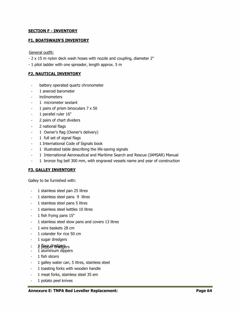
Annexure E: TNPA Bed Leveller Replacement: Page 64
SECTION F - INVENTORY
F1. BOATSWAIN'S INVENTORY
General outfit:
- 2 x 15 m nylon deck wash hoses with nozzle and coupling, diameter 2"
- 1 pilot ladder with one spreader, length approx. 5 m
F2. NAUTICAL INVENTORY
- battery operated quartz chronometer
- 1 aneroid barometer
- inclinometers
- 1 micrometer sextant
- 1 pairs of prism binoculars 7 x 50
- 1 parallel ruler 16"
- 2 pairs of chart dividers
- 2 national flags
- 1 Owner's flag (Owner's delivery)
- 1 full set of signal flags
- 1 International Code of Signals book
- 1 illustrated table describing the life-saving signals
- 1 International Aeronautical and Maritime Search and Rescue (IAMSAR) Manual
- 1 bronze fog bell 300 mm, with engraved vessels name and year of construction
F3. GALLEY INVENTORY
Galley to be furnished with:
- 1 stainless steel pan 25 litres
- 1 stainless steel pans 9 litres
- 1 stainless steel pans 5 litres
- 1 stainless steel kettles 10 litres
- 1 fish frying pans 15"
- 1 stainless steel stow pans and covers 13 litres
- 1 wire baskets 28 cm
- 1 colander for rice 50 cm
- 1 sugar dredgers
- 1 flour dredgers - 2 pepper dredgers - 1 aluminium dippers
- 1 fish slicers
- 1 galley water can, 5 litres, stainless steel
- 1 toasting forks with wooden handle
- 1 meat forks, stainless steel 35 em
- 1 potato peel knives
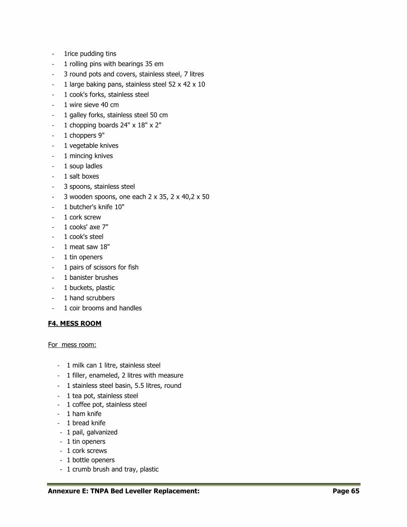
Annexure E: TNPA Bed Leveller Replacement: Page 65
- 1rice pudding tins
- 1 rolling pins with bearings 35 em
- 3 round pots and covers, stainless steel, 7 litres
- 1 large baking pans, stainless steel 52 x 42 x 10
- 1 cook's forks, stainless steel
- 1 wire sieve 40 cm
- 1 galley forks, stainless steel 50 cm
- 1 chopping boards 24" x 18" x 2"
- 1 choppers 9"
- 1 vegetable knives
- 1 mincing knives
- 1 soup ladles
- 1 salt boxes
- 3 spoons, stainless steel
- 3 wooden spoons, one each 2 x 35, 2 x 40,2 x 50
- 1 butcher's knife 10"
- 1 cork screw
- 1 cooks' axe 7"
- 1 cook's steel
- 1 meat saw 18"
- 1 tin openers
- 1 pairs of scissors for fish
- 1 banister brushes
- 1 buckets, plastic
- 1 hand scrubbers
- 1 coir brooms and handles
F4. MESS ROOM
For mess room:
- 1 milk can 1 litre, stainless steel
- 1 filler, enameled, 2 litres with measure
- 1 stainless steel basin, 5.5 litres, round
- 1 tea pot, stainless steel
- 1 coffee pot, stainless steel
- 1 ham knife
- 1 bread knife
- 1 pail, galvanized
- 1 tin openers
- 1 cork screws
- 1 bottle openers
- 1 crumb brush and tray, plastic

Annexure E: TNPA Bed Leveller Replacement: Page 66
- 1 tray
- 1 sugar basin, stainless steel
- 10 table spoons
- 10 dessert spoons
- 10 tea spoons
- 90egg spoons
- 10 table forks
- 10 dessert forks
- 90 table knives
- 1 pair of carvers, stainless steel
- 10 fish knives and forks
- 1 pepper pot
- 1 mustard pot and spoon 9 salt pot and spoon
- 1 soup ladle
- 1 sauce ladle
- 9 sugar spoon
- 1 pickle fork
- 1 toast rack (5 bars)
- 1 pair of sugar tongs
- 10 stoneware soup plates
- 10 stoneware pudding plates
- 90 stoneware dinner plates
- 10 stoneware breakfast plates
- 10 plastic egg cups
- 10 breakfast cups and saucers
- 10 coffee cups and saucers
- 1 stainless steel soup tureen
- 1 stainless steel small water jug 25 cl.
- 1 stainless steel sauce tureen
- 1 stainless steel large meat dish
- 9 stainless steel small meat dish
- 1 stainless steel vegetable dish without cover
- 1 fireproof dish
- 1 stainless steel pudding basin
- 1 cheese dish
- 1 butter dish, stainless steel
- 1 marmalade dish
- 10 drinking glasses
- 1 hair broom and handle
- 1 scrubbing brush
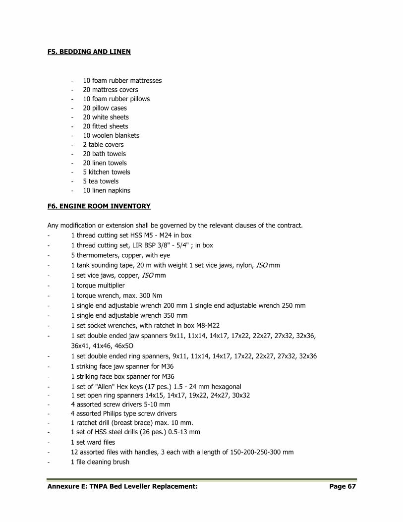
Annexure E: TNPA Bed Leveller Replacement: Page 67
F5. BEDDING AND LINEN
- 10 foam rubber mattresses
- 20 mattress covers
- 10 foam rubber pillows
- 20 pillow cases
- 20 white sheets
- 20 fitted sheets
- 10 woolen blankets
- 2 table covers
- 20 bath towels
- 20 linen towels
- 5 kitchen towels
- 5 tea towels
- 10 linen napkins
F6. ENGINE ROOM INVENTORY
Any modification or extension shall be governed by the relevant clauses of the contract.
- 1 thread cutting set HSS M5 - M24 in box
- 1 thread cutting set, LIR BSP 3/8" - 5/4" ; in box
- 5 thermometers, copper, with eye
- 1 tank sounding tape, 20 m with weight 1 set vice jaws, nylon, ISO mm
- 1 set vice jaws, copper, ISO mm
- 1 torque multiplier
- 1 torque wrench, max. 300 Nm
- 1 single end adjustable wrench 200 mm 1 single end adjustable wrench 250 mm
- 1 single end adjustable wrench 350 mm
- 1 set socket wrenches, with ratchet in box M8-M22
- 1 set double ended jaw spanners 9x11, 11x14, 14x17, 17x22, 22x27, 27x32, 32x36,
36x41, 41x46, 46x5O
- 1 set double ended ring spanners, 9x11, 11x14, 14x17, 17x22, 22x27, 27x32, 32x36
- 1 striking face jaw spanner for M36
- 1 striking face box spanner for M36
- 1 set of "Allen" Hex keys (17 pes.) 1.5 - 24 mm hexagonal
- 1 set open ring spanners 14x15, 14x17, 19x22, 24x27, 30x32
- 4 assorted screw drivers 5-10 mm
- 4 assorted Philips type screw drivers
- 1 ratchet drill (breast brace) max. 10 mm.
- 1 set of HSS steel drills (26 pes.) 0.5-13 mm
- 1 set ward files
- 12 assorted files with handles, 3 each with a length of 150-200-250-300 mm
- 1 file cleaning brush
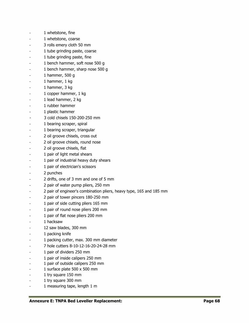
Annexure E: TNPA Bed Leveller Replacement: Page 68
- 1 whetstone, fine
- 1 whetstone, coarse
- 3 rolls emery cloth 50 mm
- 1 tube grinding paste, coarse
- 1 tube grinding paste, fine
- 1 bench hammer, soft nose 500 g
- 1 bench hammer, sharp nose 500 g
- 1 hammer, 500 g
- 1 hammer, 1 kg
- 1 hammer, 3 kg
- 1 copper hammer, 1 kg
- 1 lead hammer, 2 kg
- 1 rubber hammer
- 1 plastic hammer
- 3 cold chisels 150-200-250 mm
- 1 bearing scraper, spiral
- 1 bearing scraper, triangular
- 2 oil groove chisels, cross out
- 2 oil groove chisels, round nose
- 2 oil groove chisels, flat
- 1 pair of light metal shears
- 1 pair of industrial heavy duty shears
- 1 pair of electrician's scissors
- 2 punches
- 2 drifts, one of 3 mm and one of 5 mm
- 2 pair of water pump pliers, 250 mm
- 2 pair of engineer's combination pliers, heavy type, 165 and 185 mm
- 2 pair of tower pincers 180-250 mm
- 1 pair of side cutting pliers 165 mm
- 1 pair of round nose pliers 200 mm
- 1 pair of flat nose pliers 200 mm
- 1 hacksaw
- 12 saw blades, 300 mm
- 1 packing knife
- 1 packing cutter, max. 300 mm diameter
- 7 hole cutters 8-10-12-16-20-24-28 mm
- 1 pair of dividers 250 mm
- 1 pair of inside calipers 250 mm
- 1 pair of outside calipers 250 mm
- 1 surface plate 500 x 500 mm
- 1 try square 150 mm
- 1 try square 300 mm
- 1 measuring tape, length 1 m
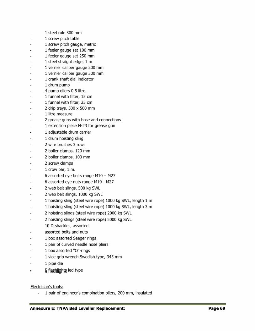
Annexure E: TNPA Bed Leveller Replacement: Page 69
- 1 steel rule 300 mm
- 1 screw pitch table
- 1 screw pitch gauge, metric
- 1 feeler gauge set 100 mm
- 1 feeler gauge set 250 mm
- 1 steel straight edge, 1 m
- 1 vernier caliper gauge 200 mm
- 1 vernier caliper gauge 300 mm
- 1 crank shaft dial indicator
- 1 drum pump
- 4 pump oilers 0.5 litre.
- 1 funnel with filter, 15 cm
- 1 funnel with filter, 25 cm
- 2 drip trays, 500 x 500 mm
- 1 litre measure
- 2 grease guns with hose and connections
- 1 extension piece N-23 for grease gun
- 1 adjustable drum carrier
- 1 drum hoisting sling
- 2 wire brushes 3 rows
- 2 boiler clamps, 120 mm
- 2 boiler clamps, 100 mm
- 2 screw clamps
- 1 crow bar, 1 m.
- 6 assorted eye bolts range M10 – M27
- 6 assorted eye nuts range M10 - M27
- 2 web belt slings, 500 kg SWL
- 2 web belt slings, 1000 kg SWL
- 1 hoisting sling (steel wire rope) 1000 kg SWL, length 1 m
- 1 hoisting sling (steel wire rope) 1000 kg SWL, length 3 m
- 2 hoisting slings (steel wire rope) 2000 kg SWL
- 2 hoisting slings (steel wire rope) 5000 kg SWL
- 10 D-shackles, assorted
- assorted bolts and nuts
- 1 box assorted Seeger rings
- 1 pair of curved needle nose pliers
- 1 box assorted "O"-rings
- 1 vice grip wrench Swedish type, 345 mm
- 1 pipe die
- 5 flashlights led type - 5 flashlights
Electrician's tools:
- 1 pair of engineer's combination pliers, 200 mm, insulated
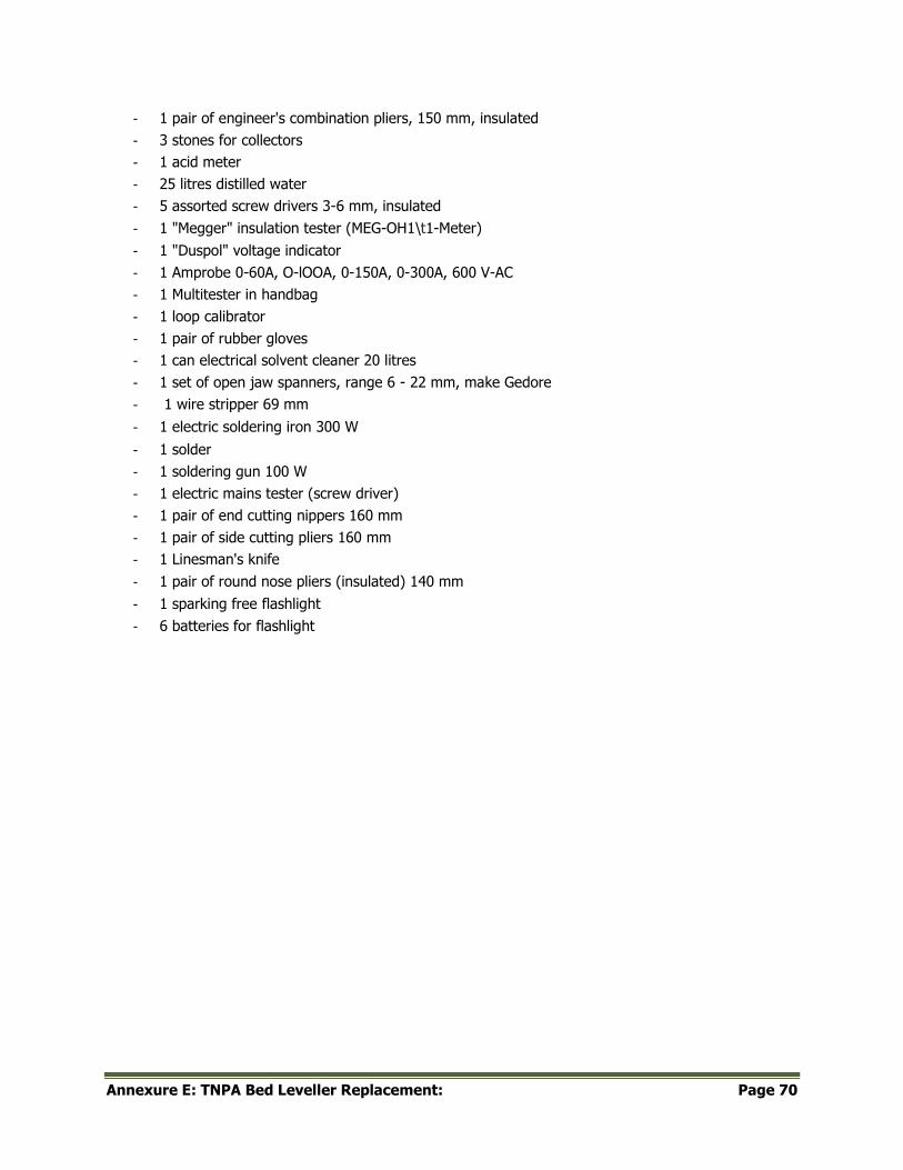
Annexure E: TNPA Bed Leveller Replacement: Page 70
- 1 pair of engineer's combination pliers, 150 mm, insulated
- 3 stones for collectors
- 1 acid meter
- 25 litres distilled water
- 5 assorted screw drivers 3-6 mm, insulated
- 1 "Megger" insulation tester (MEG-OH1\t1-Meter)
- 1 "Duspol" voltage indicator
- 1 Amprobe 0-60A, O-lOOA, 0-150A, 0-300A, 600 V-AC
- 1 Multitester in handbag
- 1 loop calibrator
- 1 pair of rubber gloves
- 1 can electrical solvent cleaner 20 litres
- 1 set of open jaw spanners, range 6 - 22 mm, make Gedore
- 1 wire stripper 69 mm
- 1 electric soldering iron 300 W
- 1 solder
- 1 soldering gun 100 W
- 1 electric mains tester (screw driver)
- 1 pair of end cutting nippers 160 mm
- 1 pair of side cutting pliers 160 mm
- 1 Linesman's knife
- 1 pair of round nose pliers (insulated) 140 mm
- 1 sparking free flashlight
- 6 batteries for flashlight
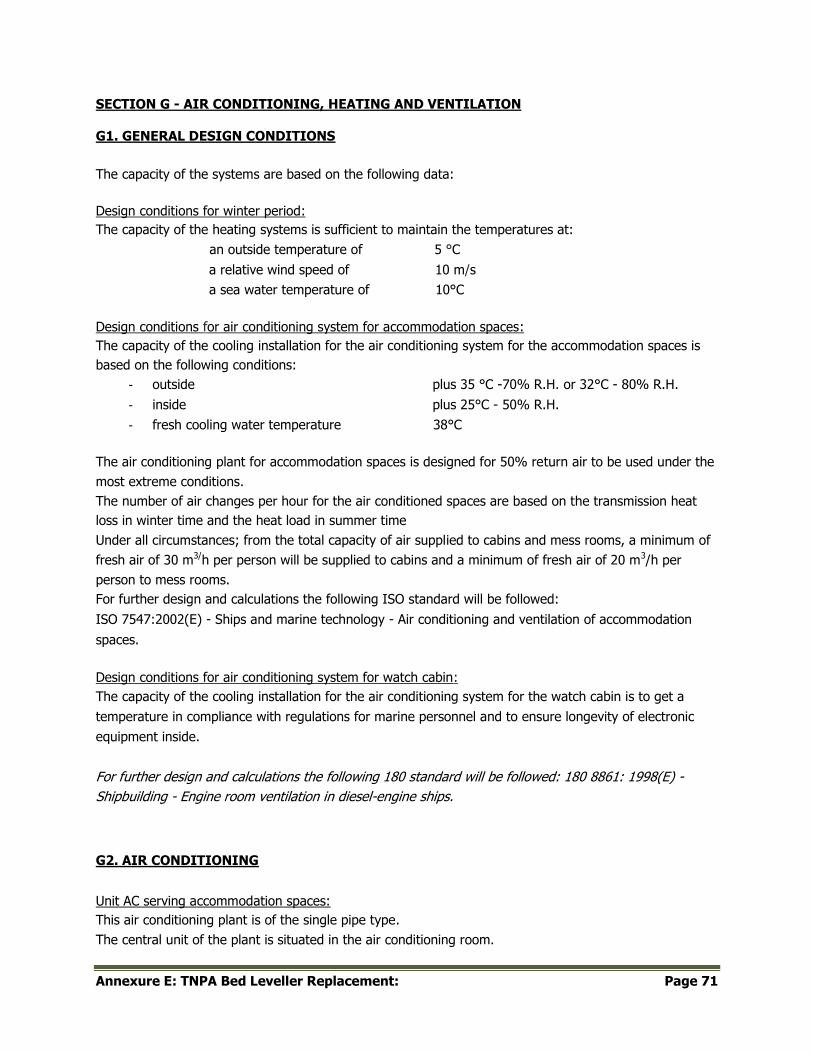
Annexure E: TNPA Bed Leveller Replacement: Page 71
SECTION G - AIR CONDITIONING, HEATING AND VENTILATION
G1. GENERAL DESIGN CONDITIONS
The capacity of the systems are based on the following data:
Design conditions for winter period:
The capacity of the heating systems is sufficient to maintain the temperatures at:
an outside temperature of 5 °C
a relative wind speed of 10 m/s
a sea water temperature of 10°C
Design conditions for air conditioning system for accommodation spaces:
The capacity of the cooling installation for the air conditioning system for the accommodation spaces is
based on the following conditions:
- outside plus 35 °C -70% R.H. or 32°C - 80% R.H.
- inside plus 25°C - 50% R.H.
- fresh cooling water temperature 38°C
The air conditioning plant for accommodation spaces is designed for 50% return air to be used under the
most extreme conditions.
The number of air changes per hour for the air conditioned spaces are based on the transmission heat
loss in winter time and the heat load in summer time
Under all circumstances; from the total capacity of air supplied to cabins and mess rooms, a minimum of
fresh air of 30 m3/h per person will be supplied to cabins and a minimum of fresh air of 20 m3/h per
person to mess rooms.
For further design and calculations the following ISO standard will be followed:
ISO 7547:2002(E) - Ships and marine technology - Air conditioning and ventilation of accommodation
spaces.
Design conditions for air conditioning system for watch cabin:
The capacity of the cooling installation for the air conditioning system for the watch cabin is to get a
temperature in compliance with regulations for marine personnel and to ensure longevity of electronic
equipment inside.
For further design and calculations the following 180 standard will be followed: 180 8861: 1998(E) -
Shipbuilding - Engine room ventilation in diesel-engine ships.
G2. AIR CONDITIONING
Unit AC serving accommodation spaces:
This air conditioning plant is of the single pipe type.
The central unit of the plant is situated in the air conditioning room.
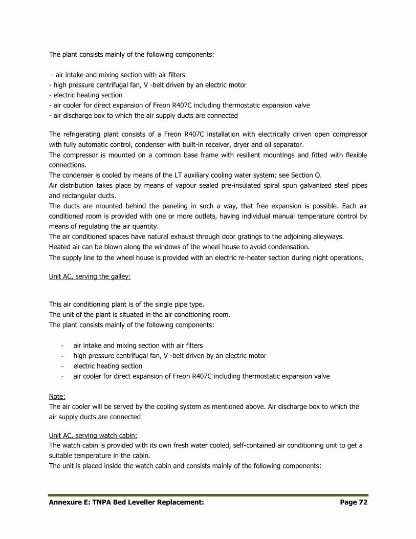
Annexure E: TNPA Bed Leveller Replacement: Page 72
The plant consists mainly of the following components:
- air intake and mixing section with air filters
- high pressure centrifugal fan, V -belt driven by an electric motor
- electric heating section
- air cooler for direct expansion of Freon R407C including thermostatic expansion valve
- air discharge box to which the air supply ducts are connected
The refrigerating plant consists of a Freon R407C installation with electrically driven open compressor
with fully automatic control, condenser with built-in receiver, dryer and oil separator.
The compressor is mounted on a common base frame with resilient mountings and fitted with flexible
connections.
The condenser is cooled by means of the LT auxiliary cooling water system; see Section O.
Air distribution takes place by means of vapour sealed pre-insulated spiral spun galvanized steel pipes
and rectangular ducts.
The ducts are mounted behind the paneling in such a way, that free expansion is possible. Each air
conditioned room is provided with one or more outlets, having individual manual temperature control by
means of regulating the air quantity.
The air conditioned spaces have natural exhaust through door gratings to the adjoining alleyways.
Heated air can be blown along the windows of the wheel house to avoid condensation.
The supply line to the wheel house is provided with an electric re-heater section during night operations.
Unit AC, serving the galley:
This air conditioning plant is of the single pipe type.
The unit of the plant is situated in the air conditioning room.
The plant consists mainly of the following components:
- air intake and mixing section with air filters
- high pressure centrifugal fan, V -belt driven by an electric motor
- electric heating section
- air cooler for direct expansion of Freon R407C including thermostatic expansion valve
Note:
The air cooler will be served by the cooling system as mentioned above. Air discharge box to which the
air supply ducts are connected
Unit AC, serving watch cabin:
The watch cabin is provided with its own fresh water cooled, self-contained air conditioning unit to get a
suitable temperature in the cabin.
The unit is placed inside the watch cabin and consists mainly of the following components:
Annexure E: TNPA Bed Leveller Replacement: Page 73
- intake section with fresh air duct connection from the engine room ventilation, re-circulation grid
and cleanable air filter
- centrifugal fan
- fresh water cooled cooling plant with condenser, compressor, evaporator, etc.; fresh water being
supplied by the LT auxiliary cooling water system, see Section 0
- sheet steel casing with supply grids
G3. HEATING SYSTEM
A heating system is only provided for the accommodation spaces in the deck house. Electric air heaters
are provided in the air conditioning unit.
G4. MECHANICAL VENTILATION SYSTEMS
Each exhaust or supply system consists mainly of:
- one axial flow fan or
- one centrifugal fan with vibration dampers and flexible connections
- supply grills of the lockable and adjustable type
- fixed exhaust grills - galvanized rectangular ducts or round spiroducts complete with suspensions
Sheet thickness related to the following dimensions of ducts:
- not-insulated spirally wound Spiroducts® pipes : 0.6 mm
- pre-insulated spirally wound Spiroducts® pipes : inner and outer duct 0.6 mm;
insulation 15 mm
- rectangular ducts :up to 350 mm;0.75 mm
- 350 - 800 mm;1.00 mm
- above 800Imm;1.25 mm
The exhaust fans of galley and sanitary spaces have such capacities, that the excess air of cabins and
mess room will be exhausted by these fans, to avoid entering of smells into these spaces.
A stainless steel canopy with grease filters is provided over the galley range.
The ventilation air is distributed over the engine room and other spaces in such a way, that no hotspots
or accumulation of oil moisture will occur and the relevant diesel engines, generators,
motors, etc. are provided with sufficient air supply.
As far as not mentioned otherwise the compartments or spaces ventilated by exhaust systems only are
supplied by air through adjoining alleyways.
Hand-operated fire valves, with open/closed indication, are fitted in the ventilation openings. An
emergency stop of the engine room fans is fitted at the outside of the engine room entrance. Engine
room exhaust will be naturally by means of the funnel.
Annexure E: TNPA Bed Leveller Replacement: Page 74
All fans in accommodation deckhouse are flexibly mounted and flexibly connected to the relevant air
ducts in order to reduce noise.
G5. NATURAL VENTILATION
Spaces, not connected to the mechanical ventilation or air conditioning system are naturally ventilated by
means of gooseneck or mushroom type ventilating shafts.
G6. AIR INLET MIST ELIMINATORS
To make aspiring of moisture or drops of water as low as possible, air inlet mist eliminators of sea water
resistant aluminium type are provided for the air conditioning systems and all mechanical ventilation
supply systems.
Air speed through gross width of mist eliminator will be 5 m/s.
Annexure E: TNPA Bed Leveller Replacement: Page 75
SECTION – H DREDGING INSTALLATION
H1. “A” frame
One hydraulically operated “A” frame with hydraulic winches for hoisting the plough off the
deck and over the aft bulwark to the sea bed as well as recovering the side wires on
plough. The winches and A frame are to have local and remote control from the Bridge.
Local controls will be fitted in a stainless steel water tight enclosure on the aft deck with a
clear view of the A frame.
H2. Plough
8 meter wide dredging ploughs (2 off) are to be supplied. One plough is to be stowed on the aft deck for
inter port voyages. Proper securing lugs for the plough are to be welded to deck.
H3. FILLING AND EMPTYING OF FORE PEAK TANK
The forepeak tank is arranged as trim tank, to be filled by means of the fire pump, in order to reduce the
vessel's trim in light ship condition
The discharge system of the fire pumps is provided with a branch pipe to the forepeak tank, fitted with a
hydraulically operated butterfly valve, The bottom of the tank is situated just above the light waterline.
Emptying of the tank will be by means of opening of the hydraulically operated butterfly valve in the
draining pipe between tank and ship's bottom or via a bilge/ballast module in accordance with class
requirements.
All butterfly valves are remote controlled from the wheel house.
Annexure E: TNPA Bed Leveller Replacement: Page 76
SECTION I - CONTROL CONSOLES AND INSTRUMENTS
I1. GENERAL
The following are installed:
- in the wheel house:
- navigation control console
- dredging control console
- 19" instruments racks
- GMDSS communication console; see Section E
control panels in engine room; one at the control position of each main diesel engine
Construction of control consoles:
The consoles with a frame of steel plates and profiles, are provided with removable panels on the front
side and hinged top cover to give good access to the inside of the console.
The top cover is flat and has an inclination.
The console has a smooth surface and is provided with a storm rail. The frame and the panels are
painted in standard colour.
The top plate on the cover is of opaque perspex, with glued on nameplates of opaque perspex with texts
engraved underneath.
Engraved texts are painted:
- yellow fluorescent for control consoles in the wheel house
- white for control panels in engine room
The electric wiring is mounted in plastic tubes and connected to terminals.
The adjustable night lighting (dimming control) over the control consoles in the wheel house consists of
UV lamps.
The instruments and texts are good visible at this lighting while it is not disturbing during night
operations.
Indicators are executed as follows:
- unless specified otherwise, square 96 mm
- without internal lighting
- in wheel house : black scale, yellow fluorescent figures and pointer
- in engine room control panels : white scale, black figures and pointer
- glass with limited reflection
Remote indicators are of the electric type.
The control apparatus and special items, such as telephones, etc., are in standard execution of the
manufacturer.
The signal lamps and push buttons; combined or not, are rectangular 24x48 mm.
The necessary push button switches / signal lamps for control console heating, dimmer devices and test
push buttons for the night lighting and the signal lamps are provided.
Annexure E: TNPA Bed Leveller Replacement: Page 77
I2. NAVIGATION CONTROL CONSOLE
A navigation control console is placed in the wheel house. The control console comprises for the
following parts:
General
- control units of window wipers
- emergency stop accommodation fans
- radar display unit with ancillary equipment
- for engine room alarm system:
- LCD indicating display unit with alphanumeric information
- separately mounted alarm signal lamps as required by the Regulatory Bodies
- indicator for:
- echo sounding equipment
- water track speed log
- wind speed and direction indicator
- remote control WT doors
Communication:
- automatic telephone set control unit:
- public address system
- general emergency alarm system
- engineers' alarm system
- bridge navigational watch alarm system
- for whistle control:
- automatic control unit
- push button - normal control
- push button - emergency control
- GMDSS VHF control unit
- AIS control/display unit
Steering:
- for steering system:
- PLC switching unit
- steering lever unit with helm indication - FU steering
- steering lever unit - NFU steering
- steering mode selector switch – FU/NFU/autopilot if fitted
- for take over:
- push button - take control
- signal lamp - rudder in service
- push button/signal lamp - start/stop - each steering gear pump
- alarm signal lamps for steering gear as required by the Regulatory Bodies
- control unit autopilot:
Annexure E: TNPA Bed Leveller Replacement: Page 78
- indicator of:
- magnetic compass
- gyro compass
- rudder position
- display unit with ancillary equipment for:
- ECDIS
- DTPS
Propulsion:
- for each propulsion control system:
- control unit with one lever for remote control and incorporated emergency telegraph
system
- selector switch - on/off emergency telegraph system
- push button signal lamp:
- finished with engine
- engine stand-by
- bridge control/take-over
- signal lamp:
- bridge control
- engine room control
- for each main diesel engine:
- speed indicator
for each propeller clutch coupling: - push button/signal lamp - in
- push button - out
- push button - emergency out
Hydraulic controls:
- push button - emergency stop hydraulic pumps
- push button - emergency closing:
Power supply part:
This part of the navigation control console comprises the distribution for the following systems: - controls
for:
- navigation lights
- dredging lights
- deck lighting
- nautical instruments
Annexure E: TNPA Bed Leveller Replacement: Page 79
I3. 19" INSTRUMENTS RACK
A combined 19" instruments rack is installed in the wheel house; comprising:
- 19" racks of 15 HE modules; on top of which a wooden table top is mounted.
The following is fitted in or on the console: - display unit echo sounding equipment central panel of fire
detection installation PC's with ancillary equipment for:
- Dredger Control System (DCS)
- Dredged Track Presentation System (DTPS)
- for each fire pump:
- push button/signal lamp - start
- push button - stop
- where applicable other instruments etc. can be fitted in this rack
I4. CONTROL PANELS ENGINE ROOM
In the engine room a control panel is fitted in the vicinity of the control position of each main diesel
engine
Each panel comprises:
- for emergency telegraph system:
- receiver/transmitter unit
- gong for audible alarm
for remote control system:
- signal lamp - engine room control
- signal lamp - bridge control
- selector switch - engine room control / bridge control
- for propeller clutch coupling:
- push button/signal lamp - in
- push button - out
for main diesel engine:
- speed indicator
- push buttons:
- speed control
- emergency stop
- reset emergency stop
- control unit HT cooling water thermostatic control valve
- control unit LT cooling water thermostatic control valve
- a PLC (see Section N) is implemented with the following functions:
- controls for diesel engine, clutches, etc. related to respective control systems
- safety devices, interlocking, etc.
- power management between major consumers as far as applicable
Annexure E: TNPA Bed Leveller Replacement: Page 80
- extended and/or adapted if required by the Regulatory Bodies
I5. PRESSURE MEASURING SYSTEMS
The following systems are provided:
For the fire pump:
A pressure measuring system of the electric type, consisting of a transmitter with built-in amplifier and
shut-off valve.
For presentation of the systems, the transmitters are connected to a SCADA system as described
above.
For Hydraulic systems:
For measuring the pressure of hydraulic systems electric type pressure measuring systems are fitted,
consisting of a transmitter with built-in amplifier and flexible hose with shut-off coupling.
For presentation of the systems, the transmitters are connected to the SCADA system as described
above.
The following indications are presented:
- one for each main hydraulic pump
I6. DREDGED TRACK PRESENTATION SYSTEM (DTPS)
The dredged track presentation system is for on-line hydrographic survey applications as well as for off-
line applications.
The DTPS system presents the dredge operator with on-line actual updates from the dredger on the
bathymetric electronic chart or DTM (Digital Terrain Module) electronic chart in absolute
positions.
With one of the DTPS tools the operator is also able to see and control the dredger between the
required profile and the actual profile.
The system is able to log and to present all relevant data.
The system will derive the following information from the several systems as specified in the
respective Sections of this Technical Specification:
- position of the vessel (GPS) - heading of the vessel
- echo sounder
- position of the plough
- average draught of the vessel (DLM)
- electronic chart display and information system (ECDIS)
The system, installed in the wheel house, consists of hardware components and software.
Hardware for DTPS:
Annexure E: TNPA Bed Leveller Replacement: Page 81
- for mounting in 19" rack in the wheel house:
- one intel i7 - 3.0 GHz gen 2 (or better) computer; complete with:
- 1 Tb hard disk
- 8 Gb RAM
- DVD/CD drive
- 8 usb port
- 1 Gb graphics card
- for control of PC: .
- data/display unit selector switch
- 17" TFT/LCD colour display unit
- ASCII type keyboard with mouse
- printing facility via the printer of the DCS system
- for mounting in/on navigation control console:
- 17" TFT/LCD colour display unit
- membrane type keyboard
- uninterrupted power supply unit (UPS) with a capacity for a transitional time of 10 minutes interface
with the Inmarsat-Fleet Broadband system for data exchange ship to shore via the DCS system
Software for DTPS computer:
- Windows XP
DTPS package; consisting of:
- Wizard configuration module; to configure all possible views, set-ups, projects and locations
- On-line dredging module; serving dredging operations dependent on the selections made with
the help of the wizard module
- Replay (data processing) module with sub-modules functioning on-line as well as offline. The
sub-modules are also available as stand-alone modules.
- The data processing package provides the various tools for preparation, editing and processing of
the dredge data. The package provides the processing of the raw dredge data into output of
various forms such as charts and matrixes.
The following sub-modules are provided:
- DESIGN:
- to design dredging working areas, survey lines, profiles, dump area's and
theoretical models
- DRAW:
- to be used for dredging equipment and to view drawings and reference points of
the dredger
- DTM VIEWER (off-line):
- to check DTM's by import and export
- volume calculations over and under dredging between design and update matrixes
Annexure E: TNPA Bed Leveller Replacement: Page 82
- Database wizard (off-line):
- for managing and/or manipulating the DTPS database
This manipulation is to exchange or delete data between two different columns in the
database.
The aim of this wizard is to save project elements from on-going or finished projects in a
company wide general database and to set-up a new project database with elements from
previous projects.
- GARP (Geographic Arithmetic Program):
- for management of the geometric database as delivered by the DTPS Navigation
system. It allows additional modifications and display of various elements in the
geodesy database.
The application can be used to test settings and perform conversions of data and
projections.
- PRINT:
- the print function can be used to print, on scale A4 size, bathymetric chart(s) / DTM
chart(s) with or without dredge tracks as well as for final charting use the validated
data.
I7. TANK SOUNDING INSTALLATION
- An electric tank sounding system will be provided for each of the following tanks:
- each water ballast tank
- each fresh drinking water tank each
technical fresh water tank each fuel
oil bunker
- fuel oil settling tank
- each fuel oil daily service tank in engine room
- fuel oil daily service tank in emergency generator room fuel
overflow tank
- dirty oil tank
- sludge tank
Each system consists of:
- pressure transducer - make DAMCOS or equivalent, mounted in/on the respective tank
- amplifier
The amplifiers are connected to the engine room alarm and monitoring system for read out and alarm.
The system is provided with a list, trim and specific gravity correction.
- The following tanks are provided with a set point for high level alarm:
- fuel overflow tank
- dirty oil tank
- sludge tank

Annexure E: TNPA Bed Leveller Replacement: Page 83
The following tanks are provided with a set point for low level alarm:
- each fuel oil daily service tank in engine room
The following tanks are provided with a set point for low as well as high level alarm.
- fuel oil settling tank
- fuel oil daily service tank in emergency generator room
Annexure E: TNPA Bed Leveller Replacement: Page 84
SECTION J - ELECTRICAL INSTALLATION
J1. GENERAL
The electrical installation and all materials are in accordance with the requirements of the Regulatory
Bodies.
Design conditions; unless specified otherwise:
- degree of protection of machines:
- on open decks ................................................................................................................ IP 56.
- in enclosed spaces .......................................................................................................... IP 44.
degree of protection of switchboards, distribution boards;
transformers, etc ............................................................................................................ IP 23.
output of machines .................................................................................... continuously 100%.
insulation of machines .................................................................................................. Class F.
temperature rise of machines ...................................................... .according to insulation Class F
ambient temperature on open decks .......................................................................... 45 deg C.
ambient temperature in enclosed spaces ..................................................................... .55deg C
relative humidity ................................................................................. . 90% at about 35 deg C
theoretical life L10h for roller bearings for machines .......................................... .at least 30000 H
Control system main switchboards:
The control system of the main switchboard is incorporated in the control systems machinery installations
- see Section N.
The electrical installation consists of the following systems:
- a 3 x 400 V-50 Hz - AC main system for supplying auxiliaries
- a 3 x 230 V-50 Hz - AC system for main lighting, emergency lighting, small consumers and other
apparatus
The system will be fed from the 400 V system via three phase transformers.
- two 24 V - DC systems for alarm systems and other appliances; each via a battery charger and DC
supply rectifier unit fed from the main supply
Capacity and arrangement of the systems:
The capacity and arrangement of the main-, auxiliary- generator and the relevant systems are
defined by following operating conditions:
1. Main generators
Each main generator is driven by its own diesel engine.
J2. ANTI - CONDENSATION HEATING
Anti-condensation heating is provided for:
- generators
- electric motors of 5.5 kW and over
Annexure E: TNPA Bed Leveller Replacement: Page 85
- transformers 400 V / 230 V
- switchboards
- control consoles
The anti-condensation heating for generators, motors and transformers is switched on automatically
when the main switch or starter concerned is switched off and the heating is signalized on the concerning
starter or switchboard.
J3. AC GENERATORS
AC main generator
The self-regulated, self-excited AC main generators are installed in the engine room, driven by a diesel
engine
The generator has the following specification:
- power factor .................................................... 0.8 @full load .
- voltage ............................................................ . 3 x 400 V
- frequency ........................................................ . 50Hz
- speed .............................................................. . 1500rpm
- degree of protection . IP 44 up to shaft level
- air inlet. .......................................................... . with filters
- air outlet . with drip cover
- method of cooling ............................................ . air cooled
- bearings .......................................................... . self-ventilated roller bearings
- temperature sensors 2 x PT1OO element in each stator winding, for
alarm and switching-off
The generator draws cooling air from the engine room and discharge the cooling air into the engine
room.
The generator is suitable for running in parallel with the auxiliary generator for take-over duty.
J4. MAIN SWITCHBOARD - 400 V
The main switchboard is situated in the switchboard room and is arranged in panels.
On the top and rear the panels are provided with steel plates and on the front with lockable doors.
The switchboards consist of but not limited to main bus bar section with:
- generator panel for AC main generator; fitted with:
- motor operated generator circuit breaker provided with no-voltage coil with delay, a direct working
magnetic short circuit security relay and a thermal overload relay as well as the necessary auxiliary
contacts
- push button - in/out - generator circuit breaker
- signal lamp for:
Annexure E: TNPA Bed Leveller Replacement: Page 86
- generator circuit breaker - in
- anti-condensation heating generator - in
A)
- ammeter with selector switch
- voltmeter with selector switch
- frequency meter
- Watt meter
- insulation monitoring system
- outgoing group for:
- emergency switchboard
- switchboard - fore ship
- transformer
- main lighting
- shore supply panel -3 x 400 V-50 Hz - 200 A, fitted with:
- hand-operated circuit breaker with interlocking device for shore supply
- signal lamp
- shore supply
- ammeter
- panels with motor starters
- synchronizing control - in/out
- speed control auxiliary generator diesel engine
signal lamps for:
- circuit breaker - in/out
- anti -condensation heating generator - in
- ammeter with selector switch
- voltmeter with selector switch
- double frequency meter
- Watt meter
- synchronoscope
J5. EMERGENCY SWITCHBOARD - 400 V
The switchboard is fed by the main switchboard and is in accordance to the classification society
requirements if needed.
A) One generator panel fitted with:
- motor operated generator circuit breaker, provided with no-voltage coil with delay and the
necessary contacts for signaling and interlocking
- signal lamp for:
- anti-condensation heating generator - in
- generator circuit breaker - in
- the necessary relays for short circuit and overload protection
- Watt meter
Annexure E: TNPA Bed Leveller Replacement: Page 87
- ammeter with selector switch
- voltmeter with selector switch frequency
meter
- measuring converter for Watt meter in main switchboard
C) Connecting panel with the main switchboard, fitted with:
- circuit breaker, provided with no-voltage coil with delay and the necessary auxiliary contacts
- voltmeter
- ammeter
D) Panels with motor starters - see below.
The switchboard complete with the necessary current and voltage transformers, fuses,
terminals, relays, busbars, earth fault signaling and wiring.
All remote controlled equipment is provided with an isolating switch.
J6. MOTORSTARTERS
Motor starters for auxiliaries with automatic stand-by function and motor starters for other auxiliaries
with an automatic function will be installed in the corresponding switchboards. All other motor
starters will be mounted at site.
Each fixed type motor starter for the electric motor of 5.5 kW and over is executed with push buttons -
start/stop - and ammeter.
Motor starters which switch automatically by means of a pressostat etc. are fitted with switch -
hand/automatic.
Unless specified otherwise; motor starters will be direct on line (DOL) starters and depending on the
final lay-out of the relevant systems, the decision will be made for the use of other types of motor
starters.
J7. SHORE SUPPLY CONNECTION BOX
A shore supply connection box 400 V-50 Hz - 200 A is provided and connected to the shore supply
section of the main switchboard - 400 V.
The box contains:
- main switch/phase selector switch
- fuses
- phase sequence meter
- terminals for shore cable connection
One hand-operated cable reel with 50 m shore supply cable and sockets is installed.
Annexure E: TNPA Bed Leveller Replacement: Page 88
J8. 32 V - AC HAND LAMP SUPPLY
For 32 V - AC hand lamp supply; 10 WT sockets with built-in transformer 230 V - AC I 32 V - AC will be
installed.
The sockets, the location of which has still to be selected, are clearly marked.
J9. ACCUMULATORS
The following accumulators are installed:
A) Two 24 V - DC lead acid accumulator with automatic charger unit and alarm device connected
to the engine room alarm system.
Each unit, fed from the respective main supply, is executed as battery charger and DC supply
rectifier unit with separated circuits and provided with a discharge circuit for uninterrupted DC
power supply and voltage limitation.
Each charger unit is complete with voltmeter, ammeters, earth fault lamp and the necessary outgoing
groups for the 24 V consumers - except the GMDSS equipment.
B) One 24 V - DC lead acid accumulator with automatic charger fed from the 230 V supply for the
emergency supply to the GMDSS equipment
The accumulators are stowed in watertight boxes of fibre glass reinforced plastic.
J10. TRANSFORMERS - 400 V / 230 V
Two identical transformer banks 400 V / 230V - 50 Hz - AC supply for lighting, small electric motors and
other appliances are provided; each having the following specification:
- voltage primary............................................. 3 x 400 V
- voltage secondary ........................................... ,. 3 x 230 V
- frequency. ............................................................. 50 Hz
- output ................................................................... 65% of the total demand
- taps ...................................................................... ± 2 % and ± 5%
Each transformer bank consists of four single phase transformers; three connected and one as
spare. I
The transformer banks are of the drip-proof, dry and air cooled type.
One of the transformer banks is connected to the main switchboard, the other one to the
emergency switchboard.
The transformer banks are of the drip-proof, dry and air cooled type.
J11. POWER DISTRIBUTION BOXES
The necessary power distribution boxes are fitted.
Each box is provided with one main switch and fuses for the outgoing groups.
Annexure E: TNPA Bed Leveller Replacement: Page 89
J12. LIGHTING DISTRIBUTION BOXES
For the lighting the necessary lighting distribution boxes with mini-circuit breakers are fitted.
J13. CABLES AND CABLE TRAYS
All cables are of a Halogen free and approved marine type - make DRAKA or equal. Where
required for interference, the cables are provided with a metal braiding. Compression type
cable glands of an approved type are used for cable terminations, For fixing the cables, cable
trays of the ladder type are used and mounted on places to Builders option.
For mounting of the cables on the trays plastic cable ties of the UV resistant type are used. The
trays are secured to bulkheads, casing etc., by means of welded strips.
Deck cables and cables exposed to mechanical damage are protected by means of galvanized solid
drawn steel pipes.
Where cables pass through decks or watertight bulkheads, watertight passages are used.
The cabling, cable tray connections, etc. will be executed according to the EMC Regulations.
J14. MAIN LIGHTING - 230 V
General:
- The electric lighting is 230 V - AC.
- In each space the lighting points are divided in two groups.
- Definition of "General measurement points":
- "General measurement points" means, in relation to any space, those points which,
measured at a height of 850 millimeters above the floor, fall on an imaginary line drawn
vertically through the following points:
- every point mid-way between every two adjacent lamps in that space;
- every point mid-way between any lamp and any position on the boundary of that
space to which that lamp is nearer than any other lamp; and
- where any part of the space available for free movement is shielded from the direct rays of
a lamp by a re-entrant angle formed in the boundary of that space, the central point of the
space so shielded
- the electric lighting in any space, mentioned hereafter, is adequate if the lamps, paint work and
other surface finishes are new, the illumination in the horizontal plane when measured at the
points specified in respect of that space is steady and is maintained, subject to a tolerance of
10% at the value prescribed in respect of those points.
Reflection factor of walls is 0.6 or better.
Deck lights:
- 2 WT floodlights 250 W SON-T type on forward side of deckhouse, directed forward
- 2 WT floodlights 250 W SON- T type on aft side of deckhouse, directed aft
- 2 WT floodlight 250 W SON- T type on the funnel, directed aft
- 2 WT halogen lights 200 W - one at each side of the funnel- to illuminate the Owner's symbols
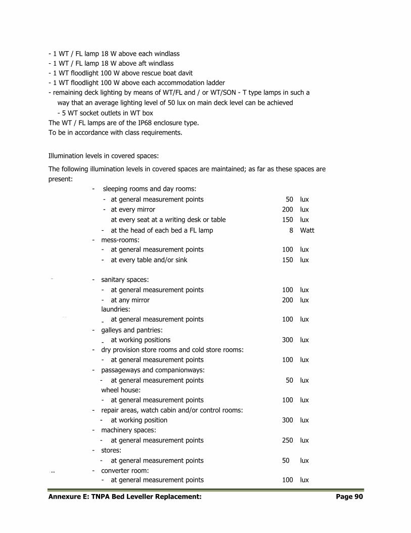
Annexure E: TNPA Bed Leveller Replacement: Page 90
- 1 WT / FL lamp 18 W above each windlass
- 1 WT / FL lamp 18 W above aft windlass
- 1 WT floodlight 100 W above rescue boat davit
- 1 WT floodlight 100 W above each accommodation ladder
- remaining deck lighting by means of WT/FL and / or WT/SON - T type lamps in such a
way that an average lighting level of 50 lux on main deck level can be achieved
- 5 WT socket outlets in WT box
The WT / FL lamps are of the IP68 enclosure type.
To be in accordance with class requirements.
Illumination levels in covered spaces:
The following illumination levels in covered spaces are maintained; as far as these spaces are
present:
- sleeping rooms and day rooms:
- at general measurement points 50 lux
- at every mirror 200 lux
at every seat at a writing desk or table 150 lux
- at the head of each bed a FL lamp 8 Watt
- mess-rooms:
- at general measurement points 100 lux
- at every table and/or sink 150 lux
-r-
-,
- sanitary spaces:
- at general measurement points 100 lux
- at any mirror 200 lux
laundries:
...--.. at general measurement points 100 lux -
- galleys and pantries:
~~----, at working positions 300 lux - - dry provision store rooms and cold store rooms:
- at general measurement points 100 lux
- passageways and companionways:
- at general measurement points 50 lux
wheel house:
- at general measurement points 100 lux
- repair areas, watch cabin and/or control rooms:
- at working position 300 lux
- machinery spaces:
- at general measurement points 250 lux
- stores:
- at general measurement points 50 lux
...
.., - converter room:
- at general measurement points 100 lux
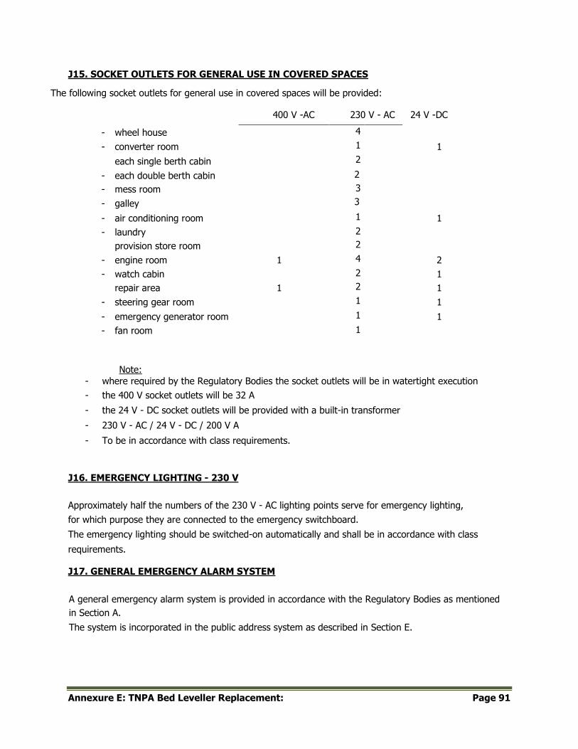
Annexure E: TNPA Bed Leveller Replacement: Page 91
J15. SOCKET OUTLETS FOR GENERAL USE IN COVERED SPACES
The following socket outlets for general use in covered spaces will be provided:
400 V -AC 230 V - AC 24 V -DC
- wheel house 4
- converter room 1 1
each single berth cabin 2
- each double berth cabin 2
- mess room 3
- galley 3
- air conditioning room 1 1
- laundry 2
provision store room 2
- engine room 1 4 2
- watch cabin 2 1
repair area 1 2 1
- steering gear room 1 1
- emergency generator room 1 1
- fan room 1
Note:
- where required by the Regulatory Bodies the socket outlets will be in watertight execution
- the 400 V socket outlets will be 32 A
- the 24 V - DC socket outlets will be provided with a built-in transformer
- 230 V - AC / 24 V - DC / 200 V A
- To be in accordance with class requirements.
J16. EMERGENCY LIGHTING - 230 V
Approximately half the numbers of the 230 V - AC lighting points serve for emergency lighting,
for which purpose they are connected to the emergency switchboard.
The emergency lighting should be switched-on automatically and shall be in accordance with class
requirements.
J17. GENERAL EMERGENCY ALARM SYSTEM
A general emergency alarm system is provided in accordance with the Regulatory Bodies as mentioned
in Section A.
The system is incorporated in the public address system as described in Section E.
Annexure E: TNPA Bed Leveller Replacement: Page 92
J18. ENGINEERS' ALARM SYSTEM
An engineers' alarm system, integrated in the alarm system as described below is provided; comprising
a buzzer in the cabin alarm unit in each engineer's cabin and in each public room as required by the
Regulatory Bodies as mentioned in Section A.
The buzzer in the engineer's cabins can be pre-selected from the alarm system in the switch
board room.
The buzzer in each public room is always activated.
The buzzers are activated at each incoming alarm.
If within a specified time the alarm is not responded, a klaxon in the alleyways of the engineers' and
an alarm signal lamp in the navigation control console in the wheel house are activated.
J19. PERSONNEL ALARM SYSTEM
For the safety supervision of the engine room watch keeping personnel a personnel alarm system,
integrated in the engine room alarm system as described below, is installed. The system can be switched-
on by means of a key controlled switch in the alleyway of the engineers' . After switching-on, the system
activates an alarm after 27 minutes in the engine room. This alarm can be reset by means of push
buttons of which the number and place has still to be determined to comply with the requirements of the
Regulatory Bodies as mentioned in Section A. If within 3 minutes the alarm is not responded, the
personnel alarm system is automatically connected to the engineers' alarm system.
J20. BRIDGE NAVIGATIONAL WATCH ALARM SYSTEM (BNWAS)
A bridge navigational watch alarm system (BNW AS) is provided in accordance with the
Regulatory Bodies as mentioned in Section A.
J21. ENGINE ROOM ALARM AND MONITORING SYSTEM
An alarm and monitoring system is provided for warning of faults in the machinery systems, the
safety systems and control systems and in addition the monitoring of analogue values as mentioned
below.
The execution of the alarm and monitoring system satisfies the requirements of the Regulatory Bodies
as mentioned in Section A.
The following systems are incorporated in the engine room alarm and monitoring system: - general
engineers' alarm system
- personnel alarm system
- computing device for the tank sounding system as described in Section L
- exhaust gas temperature alarm and monitoring system of each main diesel engine
- exhaust gas temperature alarm and monitoring system of dredge pump diesel engine
The alarm and monitoring system comprises:
Annexure E: TNPA Bed Leveller Replacement: Page 93
- in switchboard room:
- main alarm unit
- 15.1" TFT touch screen and operating push buttons
- on duty selection unit of engineers' alarm system
- control unit personal alarm system
- alarm printer
- LCD indicating display unit with alphanumeric information, in:
- technical space
- in navigation control console:
- LCD indicating display unit with alphanumeric information
- alarm annunciator unit(s) for separate alarms as required by the Regulatory Bodies
- on duty indication unit of general engineers' alarm system
- cabin alarm unit:
- each engineers' cabin
- each mess room
relevant equipment as indicator columns, rotating beam lights, signal horns etc. in the respective
spaces as required
- interface with:
- voyage data recorder (VDR) - see Section E
Beside the alarms the following indications can also be read out on the display unit in the watch cabin:
contents of the tanks of the tank sounding installation as described in Section L pressure for:
- starting air
- operating air
- lubricating oil - each main diesel engine
- temperature for:
- HT cooling water - each main diesel engine
- lubricating oil - each main diesel engine
- lubricating oil - each gearbox for propeller drive
The I/O cards - including spare cards - are provided for 256 channels (digital and analogue, however
excluding inhibits).
Power supply: 230V - AC124V - DC
Annexure E: TNPA Bed Leveller Replacement: Page 94
SECTION K - MACHINERY INSTALLATION
K1. GENERAL
The machinery installation comprises the following diesel engines:
- PS main diesel engine, driving:
- at flywheel side a propeller installation through a flexible coupling
and a reduction gearbox with built-in multiple disc clutch coupling
- The gearbox is at the propeller side
- SB main diesel engine, driving: - at flywheel side a propeller installation through a flexible coupling and a reduction gearbox with built-
in multiple disc clutch coupling
- The gearbox is at the propeller side
- Two Diesel Engines driving two main generators
- Ratings: - Engine power stated are maximum continuous ratings developed under the following conditions:
- ambient air temperature 45°C
- raw water temperature 32°C
- fresh water temperature of central cooling water system 38°C
- air pressure 1 bar
- maximum relative humidity 90 % at abt. 35°C
K2. CONTROL SYSTEMS MACHINERY INSTALLATIONS
The control systems of the machinery installations are based on independent programmable logic
controllers (PLC's), which communicate with each other over a redundant network.
The PLC system, based on ALLEN-BRADLEY - Controllogix product range, monitors and controls the
relevant systems and provides communication with the SCADA System for data exchange
The following will be provided and installed in the engine room control panels:
- for each propulsion system:
- one Programmable Logic Controller (PLC)
The system provides:
- I/O capacity for the propeller drive related signals
Annexure E: TNPA Bed Leveller Replacement: Page 95
- I/O capacity for the main diesel engine related signals
- autonomous processing of propeller drive and main diesel engine, interlocking and protection circuits as
far as not executed by the control system of the main diesel engine itself
- communication with the DCS system as described in Section L
The PLC and also the PC network communicate over an internal so-called redundant cable network.
Interaction with main switchboards:
The control systems of the main switchboard are incorporated in the above mentioned system,
comprising:
- i/o capacity for related switchboard signals
- autonomous processing of motor starters, interlocking and protection circuits, etc.
- remote starting and stopping of auxiliaries for dredging operations.
Interaction with engine room alarm and monitoring system:
The engine room alarm and monitoring system communicates with the above mentioned system for data
exchange.
K3. MAIN DIESEL ENGINES
Each of both turbocharged, after cooled, four stroke diesel engines has the following specification:
- with engine driven pumps
Each engine complete with:
- for fuel:
- engine driven fuel feed pump
- injection pump for each cylinder - duplex filter fine filter
- sheathed fuel injection pipes - pressure regulating valve
- fuel oil cooler; served by LT auxiliary cooling water system
- for lubrication: - engine driven lubricating oil pump
- built-on electrically driven pre-lubrication oil pump - lubricating oil cooler
- lubricating oil thermostatic control valve
- centrifugal filter - automatic filter
- pressure control valve - pipe connections for lubricating oil separator
- wet sump operation - for spare lubricating oil pumps
- for cooling:
Annexure E: TNPA Bed Leveller Replacement: Page 96
- separated HT and LT cooling water system; each comprising:
- engine driven cooling water pump - cooling water thermostatic control valve of the electric acting type
- box cooler, see Section 0 - pipe connections for pre-heating of HT cooling water system
- for pre-heating, see Section 0
- for spare cooling water pumps, see Section 0 - air starting motor with electromagnetic starting valve flywheel with hand turning gear
forward crankshaft extension or electric start in accordance with class requirements.
- crankcase relief valves
- exhaust silencer with spark arrestor - 35 dB(A) reducer and expansion joint on turbocharger
torsional vibration damper - if necessary electronic governing system
- engine control system to diesel engine maker's standard; however complying with the requirements of the relevant Regulatory Bodies
- instrumentation to diesel engine maker's standard; however complying with the requirements of the relevant Regulatory Bodies
- remote indication - via engine room alarm and monitoring system - of:
- lubricating oil pressure - lubricating oil temperature
- HT cooling water temperature - alarm switches to diesel engine maker's standard; however complying with the requirements of the
relevant Regulatory Bodies
- automatic shutdown at: - lubricating oil pressure - too low
- HI cooling water temperature - too high - over-speed
Note:
For the diesel engines
- 2 starting air receivers, 30 bar
- 1 set of special tools
- 1 set of tools for turbochargers
K4. AC GENERATOR DIESEL ENGINE
The auxiliary diesel generators sets are installed in the engine room. The set comprises:
- diesel engine - AC main / auxiliary generator with SAE housing; as described in Section M
- common torsion rigid base frame for diesel engine and generator
Note:
Diesel engine and close coupled generator mounted on resilient mountings on the common base frame.
The turbocharged, after-cooled, four stroke, diesel engine has the following specification:
- make : CATERPILLAR
Annexure E: TNPA Bed Leveller Replacement: Page 97
- power : each with sufficient capacity to provide all electrical power requirements
The engine complete with:
- for cooling:
- engine driven cooling water pump - thermostatic control valves
- box cooler; see Section 0 - electric immersion heater for pre-heating
- for lubrication :
- lubricating oil cooler - engine driven lubricating oil pump
- lubricating oil duplex filter - hand pump for emptying crankcase
- wet sump operation - for fuel:
- electronically controlled unit ejectors
- engine driven fuel transfer pump - hand-operated priming pump
- fuel oil duplex filter - fuel oil cooler; integrated in engine cooling water system
- water/fuel oil separator
- air starting motor with electromagnetic starting air valve flywheel with flexible coupling and hand turning gear SAE flywheel housing
- torsional vibration damper - if necessary expansion joint on turbocharger
- exhaust silencer with spark arrestor - 35 dB(A) - electronic governor with speed adjusting device for running in parallel for take-over duty
- instrumentation to diesel engine maker's standard; however complying with the requirements of the
relevant Regulatory Bodies - alarm switches to diesel engine maker's standard; however complying with the requirements of the
relevant Regulatory Bodies - automatic shutdown at:
- lubricating oil pressure - too low
- HT cooling water temperature - too high - over-speed
Note:
For the generator diesel engines: - one set of standard tools
K6. COUPLINGS FOR PROPELLER DRIVE
Between each main diesel engine and respective reduction gearbox for propeller drive a flexible coupling
is mounted.
Annexure E: TNPA Bed Leveller Replacement: Page 98
K7. COUPLINGS FOR AC MAIN GENERATOR DRIVE
Between each AC main generator a flexible coupling is mounted.
K8. GEARBOXES FOR PROPELLER DRIVE
Each propeller is driven through reduction gearbox with a primary. Each gearbox has the following
specification:
Each gearbox complete with:
- hardened and ground gears
- built-in multiple disc clutch coupling
- built-in thrust bearing
- forced lubrication with:
- gearbox driven lubricating oil pump
- built-on electrically driven stand-by lubricating oil pump
- lubricating oil cooler, served by the LT auxiliary cooling water system - lubricating oil duplex filter
- wet sump operation - instrumentation to gearbox maker's standard; however complying with the requirements of the relevant
Regulatory Bodies
- alarm switches to gearbox maker's standard; however complying with the requirements of the relevant Regulatory Bodies
- remote indication - via engine room alarm and monitoring system - of: - lubricating oil pressure
- lubricating oil temperature
K9. PROPELLER SHAFT EARTHING
To avoid potential corrosion in the ship and parts of machinery a current conductor is fitted on each
propeller shaft for earthing the propeller shaft with the hull.
K10. PROPELLER SHAFT LOCKING DEVICE
Each propeller shaft is provided with a hand-operated propeller shaft locking device.
K11. STERN TUBE AND SEALS
Each stern tube is made of thick-walled seamless steel tube welded in the ship's structure. Shaft seals
and bearings made of cast iron bushes with white metal liners are fitted at each end of the stem tube.
The housing of aft seal is of bronze and the housing of forward seal is of cast iron. The sealing rings run
on chrome steel liners.
Annexure E: TNPA Bed Leveller Replacement: Page 99
The aft seal is further provided with:
- bronze distance ring (2/2) between seal and stern tube
- special sealing ring as sand barrier - wire winder
- rope guard with net cutters, the rope guard will be made in halves
The aft stern bush has a length of 2 times the rule diameter of the propeller shaft and the forward stem
bush has a length of 1 time the rule diameter of the propeller shaft.
Means are provided for measuring the wear down of the stem bushes.
The propeller shafts are oil lubricated.
The lubricating system of each stem tube includes a gravity type lubricating oil tank mounted at a
suitable height and complete with low level alarm device, a filling pipe, a vent pipe and a drain cock.
One hand pump is installed for filling the two stern tube lubricating oil tanks.
Annexure E: TNPA Bed Leveller Replacement: Page 100
SECTION L - AUXILIARIES
L1. BILGE/FIRE/GENERAL SERVICE PUMPS
Two electrically driven, self-priming, centrifugal pumps are installed in the engine room and can be used
as:
- bilge pump
- fire pump
- general service pump
- ballast pump
Each pump, running at about 2900 rpm; has a capacity in accordance with the requirements of the
Regulatory Bodies.
Materials:
Pump casing :bronze.
Impeller :bronze
Shaft :stainless steel
Bearings :ball bearings
Shaft seal :stuffing box type
Each pump draws from:
- outboard; via two single filters - each 100% capacity - watertight compartments - if required by the Regulatory Bodies
- fore peak: - water ballast tank
Each pump discharges to:
- outboard
- fore peak - dirty water tank in engine room
- fire-fighting and deck wash system - bilge ejector in pump room
- water ballast tank
L2. EMERGENCY FIRE PUMP
One diesel driven, self-priming, centrifugal pump is installed in the engine room.
Annexure E: TNPA Bed Leveller Replacement: Page 101
The pump, running at about 2900 rpm, has a capacity in accordance with the requirements of the
Regulatory Bodies.
Materials of the pump as described in item 01.
The pump draws from:
- outboard; via a strainer
The pump discharges to:
- fire- fighting and deck wash system
For power supply the emergency fire pump is connected to the emergency switchboard.
L3. BILGE OILY WATER SEPARATOR
A bilge oily water separator, with a capacity of 1 m3/h is installed in the engine room. The separator will
produce effluent with an oil content not exceeding 15 ppm.
An oil content monitor is installed, provided with alarm when exceeding 15 ppm.
Clean bilge water is discharged overboard; the separated oil is drained off automatically to the sludge
tank.
The separator, provided with its own built-on pump, draws from:
- dirty water tank in engine room
- outboard
and discharges:
- to outboard
- dirty water tank in engine room when oil content exceeds 15 ppm
L4. WATER PRESSURE SETS
Two water pressure sets are installed:
- one serving the drinking water system - one serving the technical fresh water system.
Each pressure set consists of a vertical galvanized pressure tank with a capacity of 250 litres and an
electrically driven, self-priming, centrifugal pump, running at about 1450 rpm with an average capacity of
3 m3/h.
The pump starts and stops automatically by means of a pressure switch, mounted on the pressure tank.
Pressures at which the pump automatically starts and stops can be set at 2.5 and 4 bar respectively.
Annexure E: TNPA Bed Leveller Replacement: Page 102
The drinking water system draws from:
- drinking water tank
and discharges via pressure tank to:
- drinking water system
The technical fresh water system draws from:
- technical fresh water tank
and discharges via pressure tank to:
- technical fresh water system
Materials:
Pump casing : cast iron
Impeller : brass
Shaft : stainless steel
Bearings : ball bearings
Shaft seal : stuffing box type
L5. FRESH WATER DISINFECTION INSTALLATION
An ultraviolet disinfection installation (including pre-filter system) is installed in the engine room, serving
the drinking water system. The unit is flexibly mounted.
The installation has a capacity which is adapted to the domestic drinking water system and is fitted in the
pressure pipeline of the drinking water pressure system.
The installation consists of:
- stainless steel irradiation chamber, containing: - quartz protection pipe
- ultraviolet burner - control/monitoring box
- flow control valve in water inlet
- solenoid valve in water outlet - pre-filter system
Annexure E: TNPA Bed Leveller Replacement: Page 103
L6. DOMESTIC HOT DRINKING WATER CIRCULATING PUMP
For the closed hot drinking water circuit an electrically driven, close-coupled in-line, non-self-priming,
centrifugal circulating pump is fitted.
L7. CALORIFIERS
The following calorifiers are installed:
- serving the hot drinking water system in the ship, two thermostatically controlled electric calorifiers,
each with a capacity of 150 litres
The calorifiers are of the indirectly heated, double walled type.
L8. DRINKING WATER COOLERS
Two drinking water coolers are installed; one in the engine room and one in the mess room
Each drinking water cooler has a capacity of 28 litres per hour water of 12°C at a water inlet temperature
of 22 °C and an ambient temperature of 32°C.
L9. SEWAGE TREATMENT UNIT
A sewage treatment unit for biological treatment of the sewage discharge is installed in the technical
space, serving the separate black and grey water discharge systems of the ship. The unit, using the
vacuum toilet flushing system, meets the latest internationally accepted requirements.
The unit is divided in compartments for collection, aeration/purification and chlorinating.
The following items are mounted on the unit:
- electrically driven air blower - one electrically driven discharge pump
The discharge pump is controlled by float switches in the chlorine contact and discharge chamber
and discharge to outboard.
- A by-pass line for direct discharge overboard is provided and also an international shore
discharge connection.
- one electrically driven vacuumarator pump - control panel with all necessary switches, relays, etc. for full automatic operation chlorine dosing
system with storage tank
L10. FUEL OIL TRANSFER PUMPS
Two identical, electrically driven fuel oil transfer pumps of the screw type are installed. Each pump,
running at about 1450 rpm, has a capacity of 15 m3/h at a pressure of 3 bar.
Annexure E: TNPA Bed Leveller Replacement: Page 104
Each pump draws from:
- fuel oil bunkers
- fuel oil settling tank - fuel oil daily service tanks
- fuel oil overflow tank
and discharges to:
- fuel oil bunkers, trimming duty
- fuel oil settling tank
- fuel oil daily service tanks - bunker station
Materials:
Pump casing : cast iron
Screws : steel
Shafts : hardened and ground steel
Bearings : hardened and ground sleeve bearings
Shaft seal : lip type seal
L11. FUEL OIL SEPARATOR UNIT
In the engine room a fuel oil separator unit is installed;
comprising:
- common bedplate with sludge collecting pipe, dirty water collecting pipe, piping, fittings,
electric cabling and with built-on:
- automatic self-cleaning fuel oil separator with a capacity of 950 l/h marine diesel fuel with a
maximum viscosity of 11 cSt at 40°C at a separating temperature of 40 °C
The separator complete with:
- electrically driven fuel oil feed pump of the gear type
- pre-filter
- thermostatically controlled electric fuel oil heater to heat the fuel oil to the desired
separating temperature
- combined panel in which are mounted:
- motor starter fuel oil separator - motor starter fuel feed oil pump
- control unit fuel oil separator
Annexure E: TNPA Bed Leveller Replacement: Page 105
Note:
The feed pump for the fuel oil separator is separately mounted in the engine room.
L12. LUBRICATING OIL PUMPS
The following lubricating oil pumps are installed or supplied:
- For each main diesel engine:
- engine driven lubricating oil pump
- built-on electrically driven pre-lubricating oil pump - one loose shelf spare lubricating oil pump - ready for mounting
- For main generator diesel engines: - engine driven lubricating oil pump
- built-on hand-operated pump for emptying crankcase
- For emergency generator diesel engine:
- engine driven lubricating oil pump
- built-on hand-operated pump for emptying crankcase
- For each gearbox for propeller drive:
- gearbox driven lubricating oil pump
- built-on electrically driven stand-by lubricating oil pump
- For both stern tubes:
- one hand pump
The pump draws from:
- lubricating oil storage tank and discharges to:
- respective stem tube
L13. LUBRICATING OIL TRANSFER PUMP
One electrically driven lubricating oil transfer pump of the gear type is installed in the engine room.
The pump, running at about 1450 rpm, has a capacity of 3 m3/h at a pressure of 3 bar. The pump draws
from:
Annexure E: TNPA Bed Leveller Replacement: Page 106
- respective lubricating oil storage tank and discharges to:
- crankcase each main diesel engine - crankcase each generator diesel engine
- each gearbox for propeller drive
Materials:
Pump casing cast iron
Gears steel, hardened and ground
Shafts steel, hardened and ground
Bearings sleeve bearings
Shaft seal lip type seal
L14. SLUDGE/DIRTY OIL PUMP
The sludge/dirty oil pump is an air driven pump of the diaphragm type with a capacity of 5 m3/h at a
pressure of3 bar.
The pump draws from:
- crankcase each main diesel engine
- each gearbox for propeller drive - sludge tank:
- dirty oil tank
- dirty water tank - fuel oil overflow tank
and discharges to:
- dirty oil tank - deck connection
Materials:
Pump chamber cast aluminium.
Manifolds cast aluminium
Wetted piston stainless steel cast
Centre block aluminium
Clamping rings stainless steel.
Balls rubber (Buna-N)
Ball seats rubber (Buna-N)
Annexure E: TNPA Bed Leveller Replacement: Page 107
Diaphragms rubber (Buna-N)
L15. COOLING WATER SYSTEMS
The following fresh cooling systems are provided:
A) Independent cooling water system for: - radiator cooled emergency generator diesel engine, comprising:
- engine driven cooling water pump
- thermostatic control valve - engine driven cooling fan
- radiator with header tank with low level switch
- ac generator diesel engines, comprising:
- engine driven cooling water pump
- thermostatic control valve
- header tank with low level switch - box cooler
B) Independent low temperature (LT) cooling water system as well as an independent high temperature
(HT) cooling water system is provided for:
- each main diesel engine
Each system comprises:
- engine driven cooling fresh water pump - thermostatic control valve
- header tank: with low level switch - box cooler
At the lowest point of the system valves are provided for emptying the system to the cooling water drain
tank.
Note:
Loose shelf spare cooling water pumps - ready for mounting - are provided for the engine driven pumps
as follows:
- one HT cooling water pump for:
- each main diesel engine
- each AC generator diesel engine
- one LT cooling water pump for:
- each main diesel engine - each AC generator diesel engine
C) Low temperature auxiliary cooling water system in the engine room, comprising:
Annexure E: TNPA Bed Leveller Replacement: Page 108
- two box coolers; each 50 % capacity
- header tank: with low level switch - thermostatic control valve
- two fresh cooling water pumps, each 100 % capacity; one as stand-by - The pumps discharge to:
- fuel oil cooler of:
- each main diesel engine
- lubricating oil cooler of: - each gearbox for propeller drive
- condenser of:
- each air conditioning unit
- provision store refrigerating equipment
- hydraulic oil cooler of hydraulic power unit
At the lowest point of the system valves are provided for emptying the system to the
cooling water drain tank.
The above mentioned electrically driven pumps; running at about 1450 rpm; are of the non-self priming,
centrifugal type.
Capacity and pressure of the pumps are in accordance with the requirements for their duty.
Materials:
Pump casing . cast iron
Impeller . bronze
Shaft . stainless steel
Bearings . ball bearings
Shaft seal . mechanical seal
L16. BOX COOLERS
The fresh cooling water systems are cooled by means of box coolers as mentioned above. A box cooler
consists of a removable tube bundle fitted in a box integral with the ship's structure, with inlet openings
in the bottom and outlet openings in the side plating.
Fresh cooling water flows through the inside of the tube bundle, of which the outside is in contact with
sea water for transfer of heat.
Annexure E: TNPA Bed Leveller Replacement: Page 109
In the box a thermal-siphon circulation of sea water arises, based upon the mass differences of water
caused by temperature differences. Water with a higher temperature has a lower specific mass than
colder water.
The box coolers are suitable for ship lying idle and can be removed with empty ship.
Materials:
Pipes . Cunifer (CuNi 10 Fe)
Pipe plates . brass (CuZn40)
Covers . steel
Pipe connections . steel
Mounting frame . steel
L17. PROTECTION SYSTEM FOR BOX COOLERS
The natural anti-fouling property of the material of the Cunifer pipes will be used.
The oxide layer on the pipes is toxic for animal growth; to achieve a stable oxide layer it is important to
keep the material in balance between cathodic protection and corrosion.
The Cunifer has to keep its natural potential; therefore each box cooler is provided with its own
automatically working, electronic control unit to keep the potential of the cooler to a pre-set figure.
The unit, without external power supply, is provided with a built-in battery with a lifetime of at least five
years and a LED to indicate proper working of the unit.
The unit is connected to the pipe plate of the cooler as well as to the hull structure.
L18. PRE-HEATING SYSTEMS FOR DIESEL ENGINES
The following pre-heating systems are installed:
- For each main diesel engine:
- pre-heating unit; comprising: - electrically driven, non-self priming, centrifugal circulating pump
- thermostatically controlled electric heater
For main AC generator diesel engine:
Annexure E: TNPA Bed Leveller Replacement: Page 110
- the HT cooling water system of the auxiliary generator diesel engine is provided with an electric
immersion heater
- For emergency generator diesel engine:
- the HT cooling water system of the emergency generator diesel engine is provided with an
electric immersion heater
Capacity and pressure of the pumps and heaters are in accordance with the requirements of their duty.
The necessary thermostatic control valves are fitted.
L19. FRESH COOLING WATER TRANSFER PUMP
The following fresh cooling water systems can be drained off to the fresh cooling water drain tank which
is incorporated in the ship's structure:
- HT cooling water system of:
- each main diesel engine
- each main AC diesel engine
LT cooling water system of:
- each main diesel engine
- each main AC diesel engine
An air driven pump of the diaphragm type with a capacity of 1 m3/h at a pressure of 3 bar is installed to
refill the relevant cooling water system.
The pump draws from:
- fresh cooling water drain tank
and discharges to:
- fresh cooling water drain tank
- HT cooling water system of: - each main diesel engine
- each main Ac diesel engine
- LT cooling water system of:
- each main diesel engine - each main AC diesel engine
Annexure E: TNPA Bed Leveller Replacement: Page 111
- LT auxiliary cooling water system
Materials of the pump as described for the sludge/dirty oil pump as mentioned above.
L20. STARTING AIR COMPRESSORS
The following starting air compressors are installed:
- two electrically driven starting air compressors in the engine room
- Each compressor, running at about 1450 rpm, has a capacity of about 17 m3/h F.A.D. at a pressure
of 30 bar. - The compressors of the air cooled type are arranged for automatic operation and supply air to the
starting air receivers as described below. - one hand-operated emergency air compressor for starting from "dead ship" in the emergency
generator room
The compressor is mounted on a 30 litres air receiver which is complete with pressure gauge and
safety valve.
L21. STARTING AIR RECEIVERS
The following starting air receivers are installed:
- two main starting air receivers each with a capacity of 355 litres - 30 bar in the engine room for
starting of the diesel engines in the engine room
- one starting air receiver with a capacity of 125 litres - 30 bar in the emergency generator room for starting the emergency generator diesel engine
- The receiver is kept under pressure by the main starting air receivers. - one starting air receiver with a capacity of 30 litres - 30 bar for starting from "dead ship" as
described above.
The receiver is kept under pressure by the main starting air receivers.
L23. EXHAUST SILENCERS
The exhaust gas pipe line of each diesel engine is provided with an exhaust silencer with spark
arrestor.
To reduce the exhaust sound level, special attention will be paid to the exhaust silencers of the main
diesel engines.
Annexure E: TNPA Bed Leveller Replacement: Page 112
SECTION M - HYDRAULIC INSTALLATION
M1. MAIN HYDRAULIC SYSTEM
The main hydraulic power unit is installed in the engine room, comprising a hydraulic oil tank made of
stainless steel X2CrNi 19-11 (AISI 304L) and the following electrically driven hydraulic pump sets:
- two main pumps of the variable displacement axial piston type including internal pilot oil/feed oil system.
The capacity calculation of the pumps is based on the highest demand
- butterfly valves in fire pump pipe lines
- each windlass - “A” frame cylinders and winch
Furthermore the hydraulic power unit complete with:
- level gauge - thermometer
- de-aerating valve
- duplex filter in the main return pipe line - fresh water cooled hydraulic oil cooler, served by the LT auxiliary cooling water
system
- flexible hoses between suction and discharge pipe line of each pump
- piping, flanges, pipe couplings, measuring connections (Minimess), valve panels, safety
- valves and remaining fittings - all solenoid operated valves are of the electric pilot controlled type, in addition the solenoid
operated valves are provided with built-in signal lamp(s) for indication of the excitation - alarm switches for:
- level hydraulic oil tank - low
- level hydraulic oil tank - too low - stop main hydraulic pumps - oil temperature - too high
- clogged filter in main return pipeline - electric equipment, wired up to a common connection / control box
Note:
- The design pressure of the system will be 250 bar.
- Each pump set - running at about 1450 rpm - comprises an electric motor, flexible coupling and hydraulic pump; in addition each pump set is also mounted on anti-vibration mountings.
- Hydraulic oil used for all hydraulic systems will be of the mineral oil type - All calculations for the hydraulic system are based on a momentary viscosity of the hydraulic oil of
50 cSt - After final installation the complete system is filled with the final hydraulic oil.
- After sea trials the filter will be checked and cleaned.
Annexure E: TNPA Bed Leveller Replacement: Page 113
M2. HYDRAULIC CYLINDERS
Depending on their service, the hydraulic cylinders are of the oscillating type or of the flange mounted
type.
Materials:
Cylinder shell: steel
Piston rod:
- A frame steel, nickel-plated (0.06 mm) and chromium-plated (0.04 mm)
M3. OPERATION OF THE SYSTEM
The operation is electric-hydraulic via PLC's.
The following controls are situated in the several control consoles in the wheel house:
- starting and stopping of hydraulic pumps
- A frame system
- butterfly valves in fire pump pipe lines
- each emergency closing device
- each windlass
The following controls are situated at site:
- each windlass
- A frame cylinders and winch
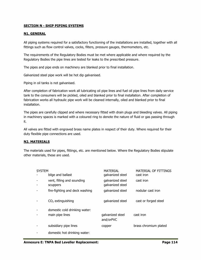
Annexure E: TNPA Bed Leveller Replacement: Page 114
SECTION N - SHIP PIPING SYSTEMS
N1. GENERAL
All piping systems required for a satisfactory functioning of the installations are installed, together with all
fittings such as flow control valves, cocks, filters, pressure gauges, thermometers, etc.
The requirements of the Regulatory Bodies must be met where applicable and where required by the
Regulatory Bodies the pipe lines are tested for leaks to the prescribed pressure.
The pipes and pipe ends on machinery are blanked prior to final installation.
Galvanized steel pipe work will be hot dip galvanised.
Piping in oil tanks is not galvanised.
After completion of fabrication work all lubricating oil pipe lines and fuel oil pipe lines from daily service
tank to the consumers will be pickled, oiled and blanked prior to final installation. After completion of
fabrication works all hydraulic pipe work will be cleaned internally, oiled and blanked prior to final
installation.
The pipes are carefully clipped and where necessary fitted with drain plugs and bleeding valves. All piping
in machinery spaces is marked with a coloured ring to denote the nature of fluid or gas passing through
it.
All valves are fitted with engraved brass name plates in respect of their duty. Where required for their
duty flexible pipe connections are used.
N2. MATERIALS
The materials used for pipes, fittings, etc. are mentioned below. Where the Regulatory Bodies stipulate
other materials, these are used.
SYSTEM MATERIAL MATERIAL OF FITTINGS - bilge and ballast galvanized steel cast iron
- vent, filling and sounding galvanized steel cast iron
- scuppers galvanized steel
- fire-fighting and deck washing galvanized steel nodular cast iron
- CO2 extinguishing galvanized steel cast or forged steel
- domestic cold drinking water:
- main pipe lines galvanized steel cast iron
and/orPVC
- subsidiary pipe lines copper brass chromium plated
- domestic hot drinking water:
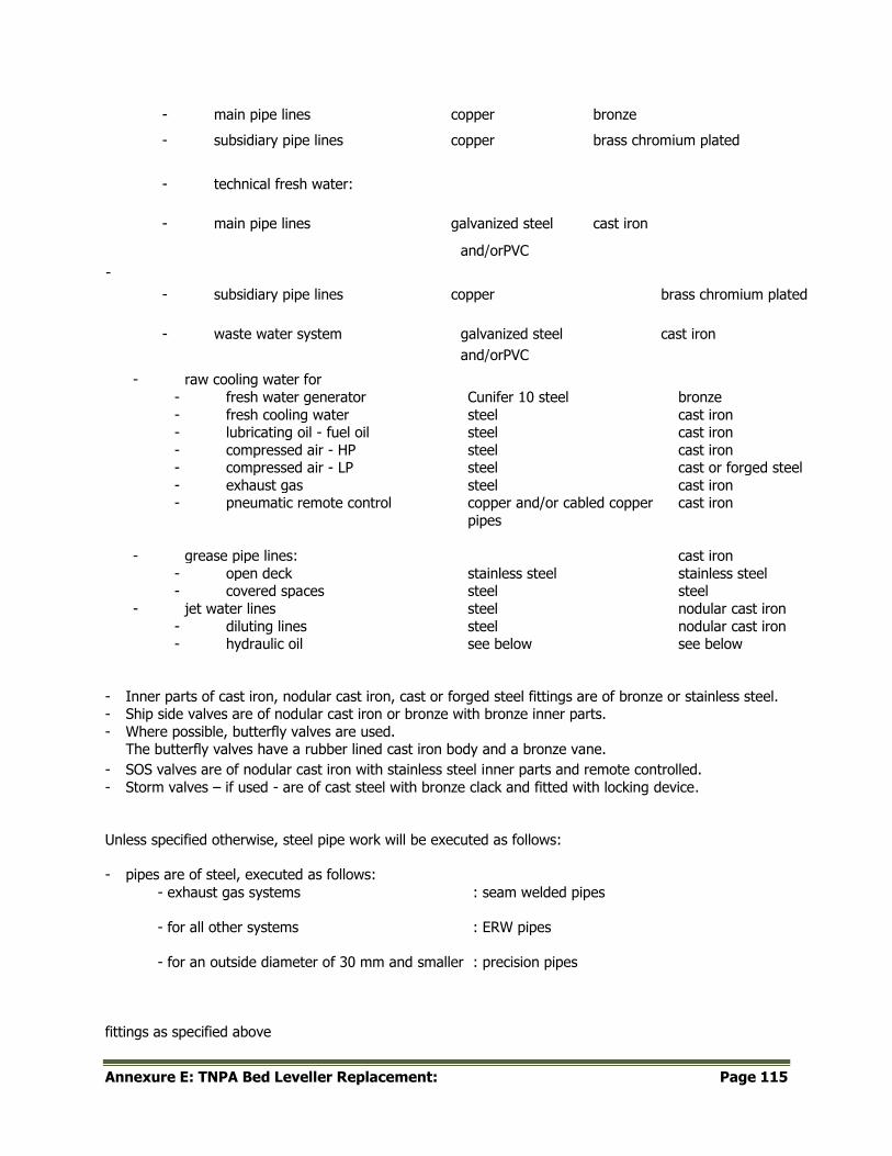
Annexure E: TNPA Bed Leveller Replacement: Page 115
- main pipe lines copper bronze
- subsidiary pipe lines copper brass chromium plated
- technical fresh water:
- main pipe lines galvanized steel cast iron
-
and/orPVC
- subsidiary pipe lines copper brass chromium plated
- waste water system galvanized steel cast iron
and/orPVC
- raw cooling water for
- fresh water generator Cunifer 10 steel bronze
- fresh cooling water steel cast iron - lubricating oil - fuel oil steel cast iron
- compressed air - HP steel cast iron - compressed air - LP steel cast or forged steel
- exhaust gas steel cast iron - pneumatic remote control copper and/or cabled copper
pipes
cast iron
- grease pipe lines: cast iron
- open deck stainless steel stainless steel - covered spaces steel steel
- jet water lines steel nodular cast iron
- diluting lines steel nodular cast iron - hydraulic oil see below see below
- Inner parts of cast iron, nodular cast iron, cast or forged steel fittings are of bronze or stainless steel. - Ship side valves are of nodular cast iron or bronze with bronze inner parts.
- Where possible, butterfly valves are used. The butterfly valves have a rubber lined cast iron body and a bronze vane.
- SOS valves are of nodular cast iron with stainless steel inner parts and remote controlled.
- Storm valves – if used - are of cast steel with bronze clack and fitted with locking device.
Unless specified otherwise, steel pipe work will be executed as follows:
- pipes are of steel, executed as follows:
- exhaust gas systems : seam welded pipes
- for all other systems : ERW pipes
- for an outside diameter of 30 mm and smaller : precision pipes
fittings as specified above
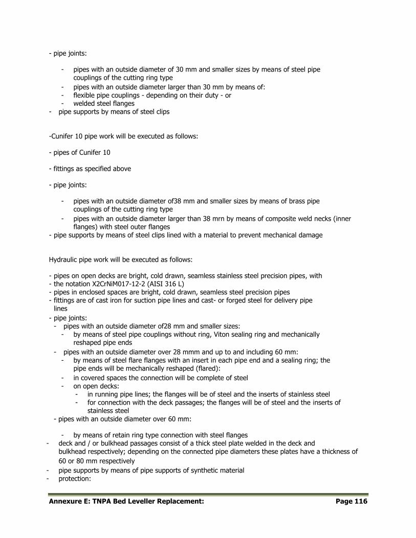
Annexure E: TNPA Bed Leveller Replacement: Page 116
- pipe joints:
- pipes with an outside diameter of 30 mm and smaller sizes by means of steel pipe
couplings of the cutting ring type
- pipes with an outside diameter larger than 30 mm by means of:
- flexible pipe couplings - depending on their duty - or - welded steel flanges
- pipe supports by means of steel clips
-Cunifer 10 pipe work will be executed as follows:
- pipes of Cunifer 10
- fittings as specified above
- pipe joints:
- pipes with an outside diameter of38 mm and smaller sizes by means of brass pipe couplings of the cutting ring type
- pipes with an outside diameter larger than 38 mrn by means of composite weld necks (inner flanges) with steel outer flanges
- pipe supports by means of steel clips lined with a material to prevent mechanical damage
Hydraulic pipe work will be executed as follows:
- pipes on open decks are bright, cold drawn, seamless stainless steel precision pipes, with - the notation X2CrNiM017-12-2 (AISI 316 L)
- pipes in enclosed spaces are bright, cold drawn, seamless steel precision pipes - fittings are of cast iron for suction pipe lines and cast- or forged steel for delivery pipe
lines
- pipe joints: - pipes with an outside diameter of28 mm and smaller sizes:
- by means of steel pipe couplings without ring, Viton sealing ring and mechanically reshaped pipe ends
- pipes with an outside diameter over 28 mmm and up to and including 60 mm:
- by means of steel flare flanges with an insert in each pipe end and a sealing ring; the pipe ends will be mechanically reshaped (flared):
- in covered spaces the connection will be complete of steel
- on open decks: - in running pipe lines; the flanges will be of steel and the inserts of stainless steel
- for connection with the deck passages; the flanges will be of steel and the inserts of stainless steel
- pipes with an outside diameter over 60 mm:
- by means of retain ring type connection with steel flanges - deck and / or bulkhead passages consist of a thick steel plate welded in the deck and
bulkhead respectively; depending on the connected pipe diameters these plates have a thickness of
60 or 80 mm respectively
- pipe supports by means of pipe supports of synthetic material
- protection:
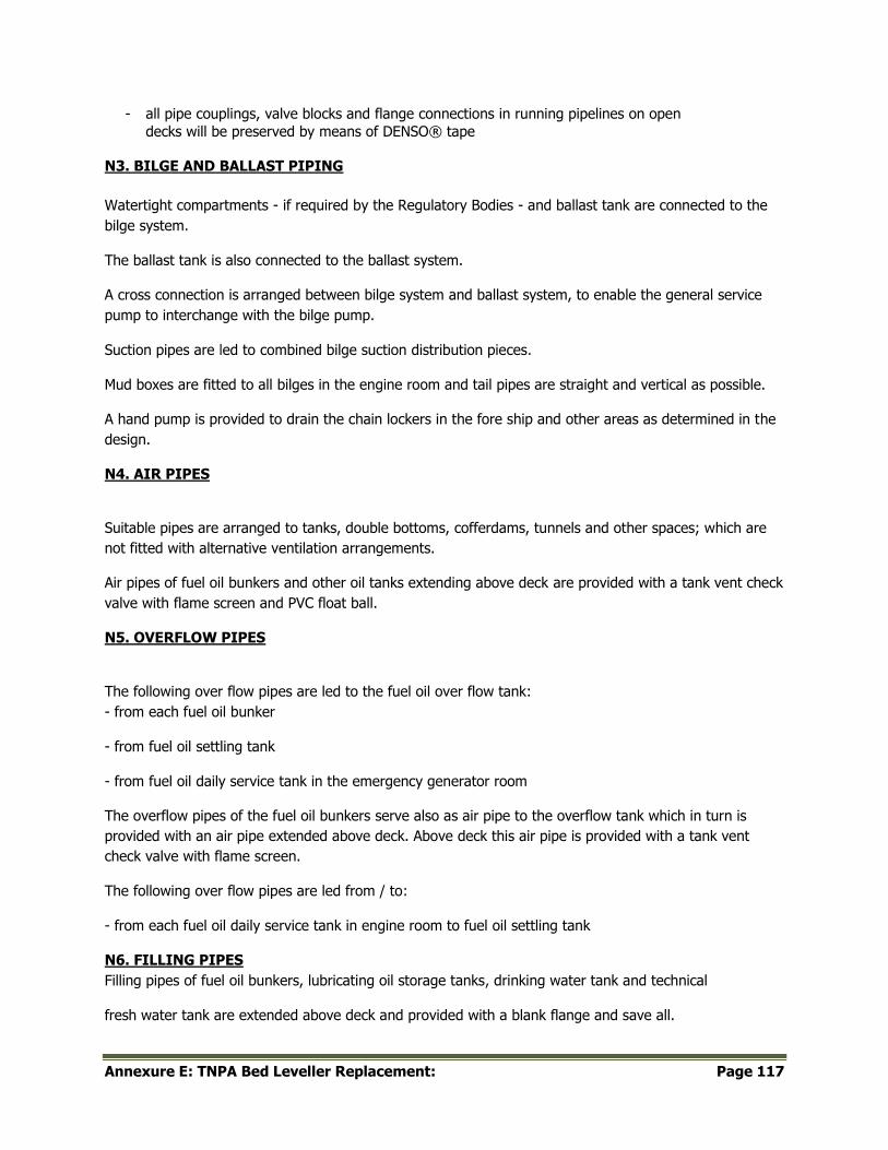
Annexure E: TNPA Bed Leveller Replacement: Page 117
- all pipe couplings, valve blocks and flange connections in running pipelines on open
decks will be preserved by means of DENSO® tape
N3. BILGE AND BALLAST PIPING
Watertight compartments - if required by the Regulatory Bodies - and ballast tank are connected to the
bilge system.
The ballast tank is also connected to the ballast system.
A cross connection is arranged between bilge system and ballast system, to enable the general service
pump to interchange with the bilge pump.
Suction pipes are led to combined bilge suction distribution pieces.
Mud boxes are fitted to all bilges in the engine room and tail pipes are straight and vertical as possible.
A hand pump is provided to drain the chain lockers in the fore ship and other areas as determined in the
design.
N4. AIR PIPES
Suitable pipes are arranged to tanks, double bottoms, cofferdams, tunnels and other spaces; which are
not fitted with alternative ventilation arrangements.
Air pipes of fuel oil bunkers and other oil tanks extending above deck are provided with a tank vent check
valve with flame screen and PVC float ball.
N5. OVERFLOW PIPES
The following over flow pipes are led to the fuel oil over flow tank:
- from each fuel oil bunker
- from fuel oil settling tank
- from fuel oil daily service tank in the emergency generator room
The overflow pipes of the fuel oil bunkers serve also as air pipe to the overflow tank which in turn is
provided with an air pipe extended above deck. Above deck this air pipe is provided with a tank vent
check valve with flame screen.
The following over flow pipes are led from / to:
- from each fuel oil daily service tank in engine room to fuel oil settling tank
N6. FILLING PIPES
Filling pipes of fuel oil bunkers, lubricating oil storage tanks, drinking water tank and technical
fresh water tank are extended above deck and provided with a blank flange and save all.
Annexure E: TNPA Bed Leveller Replacement: Page 118
N7. SOUNDING PIPES
All sounding pipes are provided with a bronze screw cap and where required by the Regulatory
Bodies extended above deck.
Sounding pipes of tanks in engine rooms are supplied with a stand pipe and bronze self-closing
sounding cock.
Striking pads are fitted under sounding pipes in all tanks and compartments.
N8. SCUPPERS
Scuppers sufficient in number and size are fitted, in all-weather exposed decks of deckhouse and led to
the next lower deck.
Scupper pipes in floors in sanitary spaces, galley, passages, etc. are provided with a water lock and led to
a main drain.
N9. FIRE FIGHTING AND DECK WASH SYSTEM
The combined fire-fighting and deck wash system can be supplied from the bilge pump, general service
pump and the emergency fire pump.
The place and number of fire-fighting and deck wash valves and the diameter of the piping is in
accordance with the requirements of the Regulatory Bodies.
Two international shore connections complying with the requirements of the Regulatory Bodies are
provided.
Also each hawse pipe is connected to the system for flushing the anchor chains. The valves for this piping
are fitted on the forecastle deck and aft deck respectively.
N10. DOMESTIC PIPE LINES
General:
For each two deck layers a main pipeline is installed for supply of domestic:
- technical fresh water
- cold drinking water
- hot drinking water
Annexure E: TNPA Bed Leveller Replacement: Page 119
Each main pipeline or main ring pipeline will serve the relevant sanitary consumers of concerned deck
layers.
Subsidiary supply lines to consumers are each provided with a stop valve.
Technical fresh water system:
The technical fresh water tank is connected to the technical fresh water pressure set from which a pipe
line is led to:
- WC's
- each washing machine
- dish washing machine
- window wipers
- fresh cooling water systems of diesel engines; for supply purposes only
- auxiliary LT cooling water system; for supply purposes only
- separator unit
- tap for cleaning purposes in:
- provision store
- laundry
- galley - each main and AC generator diesel engine for washing turbo charger
Cold drinking water system:
The drinking water tank is connected to the drinking water pressure set from which a pipe line is led to:
- tap on each deckhouse tier outside - wash-hand basins;
- showers
- sink in: - galley
- pantry - wash trough in laundry
- drinking water coolers
- water boiler in pantry
Hot drinking water system:
Annexure E: TNPA Bed Leveller Replacement: Page 120
The hot drinking water system is a closed circuit fitted with an electrically driven circulating pumps and
calorifiers and kept under pressure by the drinking water pressure set.
Hot drinking water is supplied to:
- wash-hand basins
- showers
- sink in:
- galley - each pantry
- wash trough in laundry
Waste water systems:
The separate black and grey water pipe systems in fore ship are each provided with siphons and are led
into separate collecting pipes which end into the sewage unit with by-pass for direct discharge overboard.
The soil pipe of the galley is provided with a grease trap.
The discharge pump of the sewage unit can discharge the treated water to:
- outboard via storm valves with locking device
- an international shore connection
The storm valves are positioned above the light water line.
Black and grey water pipe systems in the aft ship are also provided with siphons and are led into
common collecting pipes which end into the sewage pump unit in the engine room with by-pass for direct
discharge overboard.
Where necessary, the collecting pipes are provided with vent pipes with gooseneck.
N11. COMPRESSED AIR SYSTEMS
The following systems are provided:
A) A HP compressed air system operating at 30 bar for starting the diesel engines.
The system comprises the air receivers and starting air compressors as specified in Section O.
A pipe line is led to:
Annexure E: TNPA Bed Leveller Replacement: Page 121
- diesel engines
- air whistle
- LP compressed air system
- control air system
B) A LP compressed air system operating at 9.5 bar for pneumatic tools and other appliances.
The system comprises the air receiver and working air compressor as specified in Section O.
A pipe line is led to:
- pressure tank of each domestic pressure water set
- air driven sludge/dirty oil pump
- air driven fresh water transfer pump
- control air system; for emergency purposes
The following working air connections are provided:
- two in the engine room - one in the engine room repair area
- two on main deck PS and starboard midship -
A connection is provided between HP and LP compressed air system via a pressure reducing valve.
C) A control air system operating at 10bar; fed by the HP compressed air system via pressure reducing
valves, air filters and water separators. For emergency the control air system can also be connected to the LP compressed air system.
The control air system furthermore provided with an electrically driven compressed air dryer and air
receiver; adapted to the requirements of this system.
A pipe line is led to:
- each main diesel engine
- each main AC generator diesel engine
- bilge oily water separator
- fuel oil separator unit
- SOS valve system
N12. EXHAUST GAS SYSTEMS
The exhaust gas pipe lines of diesel engines are each provided with a silencer with spark arrestor and the
necessary expansion pieces, vibration dampers and flexible connections to allow free expansion and to
prevent vibration.

Annexure E: TNPA Bed Leveller Replacement: Page 122
At a suitable place, each exhaust gas pipeline is fitted with a drain point.
N13. INSULATION
The exhaust gas pipe lines of diesel engines are insulated and externally covered with aluminium plates.
The ring lines for domestic hot and cold water inside the accommodation are insulated by a synthetic
foam rubber material


![Transnet]...TRANSNET FRAIGHT RAIL, a division of TRANSNET SOC LTD Registration Number 1990/000900/30 [thereinafter referred to as Transnet] REQUEST FOR QUOTATION …](https://img.pdfslide.net/doc/110x75/6050751b455b0f3d741c0d14/transnet-transnet-fraight-rail-a-division-of-transnet-soc-ltd-registration.jpg)


![TRANSNET SOC LTD Transnet] ONLY · 10 Specification/Scope of Work ... Locomotive movement facility . Main Infrastructure: PREVIEW COPY ... • Workshop • Offices](https://img.pdfslide.net/doc/110x75/5ada130c7f8b9a137f8cf587/transnet-soc-ltd-transnet-specificationscope-of-work-locomotive-movement-facility.jpg)