Embed Size (px)
Citation preview
Surgical Technique
Antegrade Femoral Nail (AFN)
This publication is not intended for distribution in the USA.
Instruments and implantsapproved by the AO Foundation.

Image intensifier control
This description alone does not provide sufficient background for direct use of DePuy Synthes products. Instruction by a surgeon experienced in handling these products is highly recommended.
Processing, Reprocessing, Care and MaintenanceFor general guidelines, function control and dismantling of multi-part instruments, as well as processing guidelines for implants, please contact your local sales representative or refer to:http://emea.depuysynthes.com/hcp/reprocessing-care-maintenanceFor general information about reprocessing, care and maintenance of Synthes reusable devices, instrument trays and cases, as well as processing of Synthes non-sterile implants, please consult the Important Information leaflet (SE_023827) or refer to: http://emea.depuysynthes.com/hcp/reprocessing-care-maintenance
Antegrade Femoral Nail (AFN) Surgical Technique DePuy Synthes 1
Contents
Introduction Indications/Contraindications 2
AO Principles 3
AFN implants 4
Surgical Technique Preparation 6
Surgical technique for the AFN 10
Proximal locking 19
Distal locking 31
Implant removal 36 – Alternative Technique – Extraction Hook 39
For removal of broken nail
Cleaning 43
Product Information Implants 44
Instruments 47
Literature 50
MRI Information 51
2 DePuy Synthes Antegrade Femoral Nail (AFN) Surgical Technique
Indications/Contraindications
Indications
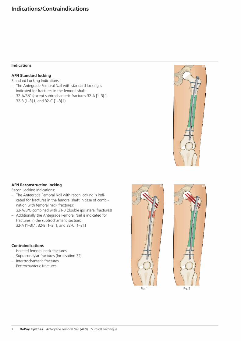
AFN Standard lockingStandard Locking Indications: – The Antegrade Femoral Nail with standard locking is
indicated for fractures in the femoral shaft: – 32-A/B/C (except subtrochanteric fractures 32-A [1–3].1,
32-B [1–3].1, and 32-C [1–3].1)
AFN Reconstruction lockingRecon Locking Indications: – The Antegrade Femoral Nail with recon locking is indi-
cated for fractures in the femoral shaft in case of combi-nation with femoral neck fractures: 32-A/B/C combined with 31-B (double ipsilateral fractures)
– Additionally the Antegrade Femoral Nail is indicated for fractures in the subtrochanteric section: 32-A [1–3].1, 32-B [1–3].1, and 32-C [1–3].1
Contraindications – Isolated femoral neck fractures – Supracondylar fractures (localisation 32) – Intertrochanteric fractures – Pertrochanteric fractures
Fig. 1 Fig. 2
1
4
2
3
4_Priciples_03.pdf 1 05.07.12 12:08
4 DePuy Synthes Expert Lateral Femoral Nail Surgical Technique
AO PRINCIPLES
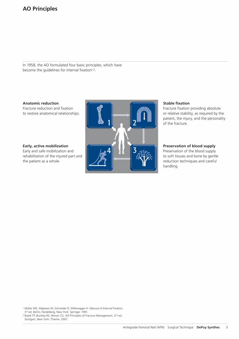
In 1958, the AO formulated four basic principles, which have become the guidelines for internal fixation1, 2.
1 Müller ME, M Allgöwer, R Schneider, H Willenegger. Manual of Internal Fixation. 3rd ed. Berlin Heidelberg New York: Springer. 1991.
2 Rüedi TP, RE Buckley, CG Moran. AO Principles of Fracture Management. 2nd ed. Stuttgart, New York: Thieme. 2007.
Anatomic reductionFracture reduction and fixation to restore anatomical relationships.
Early, active mobilizationEarly and safe mobilization and rehabilitation of the injured part and the patient as a whole.
Stable fixationFracture fixation providing abso-lute or relative stability, as required by the patient, the injury, and the personality of the fracture.
Preservation of blood supplyPreservation of the blood supply to soft tissues and bone by gentle reduction techniques and careful handling.
Antegrade Femoral Nail (AFN) Surgical Technique DePuy Synthes 3
AO Principles
1 Müller ME, Allgöwer M, Schneider R, Willenegger H. Manual of Internal Fixation. 3rd ed. Berlin, Heidelberg, New York: Springer. 1991.
2 Rüedi TP, Buckley RE, Moran CG. AO Principles of Fracture Management. 2nd ed. Stuttgart, New York: Thieme. 2007.
Stable fixationFracture fixation providing absolute or relative stability, as required by the patient, the injury, and the personality of the fracture.
Anatomic reductionFracture reduction and fixation to restore anatomical relationships.
Early, active mobilizationEarly and safe mobilization and rehabilitation of the injured part and the patient as a whole.
Preservation of blood supplyPreservation of the blood supply to soft tissues and bone by gentle reduction techniques and careful handling.
In 1958, the AO formulated four basic principles, which have become the guidelines for internal fixation1,2.
4 DePuy Synthes Antegrade Femoral Nail (AFN) Surgical Technique
AFN implants
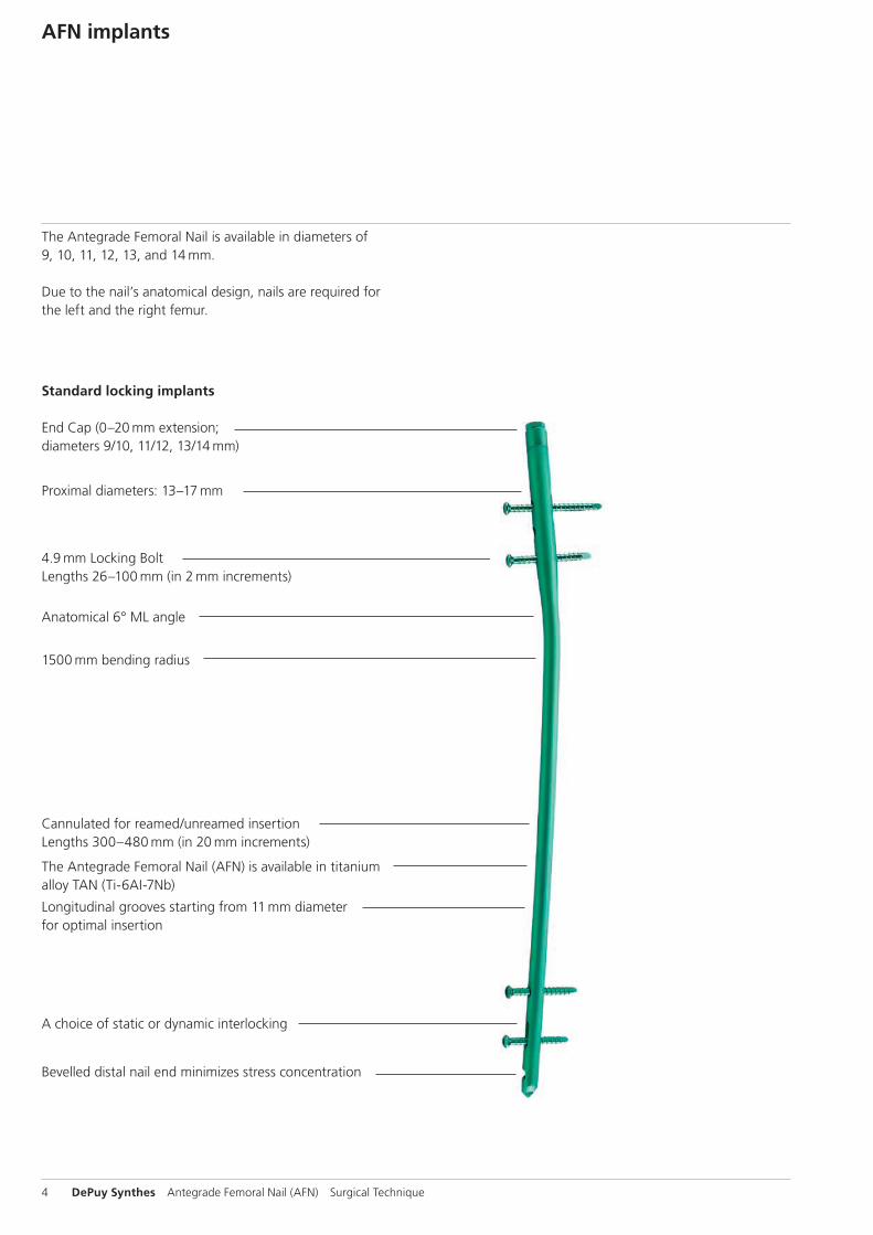
The Antegrade Femoral Nail is available in diameters of 9, 10, 11, 12, 13, and 14 mm.
Due to the nail’s anatomical design, nails are required for the left and the right femur.
Standard locking implants
End Cap (0–20 mm extension; diameters 9/10, 11/12, 13/14 mm)
4.9 mm Locking Bolt Lengths 26–100 mm (in 2 mm increments)
Cannulated for reamed/unreamed insertion Lengths 300–480 mm (in 20 mm increments)
The Antegrade Femoral Nail (AFN) is available in titanium alloy TAN (Ti-6AI-7Nb)
Longitudinal grooves starting from 11 mm diameter for optimal insertion
Bevelled distal nail end minimizes stress concentration
A choice of static or dynamic interlocking
1500 mm bending radius
Anatomical 6° ML angle
Proximal diameters: 13–17 mm
Antegrade Femoral Nail (AFN) Surgical Technique DePuy Synthes 5
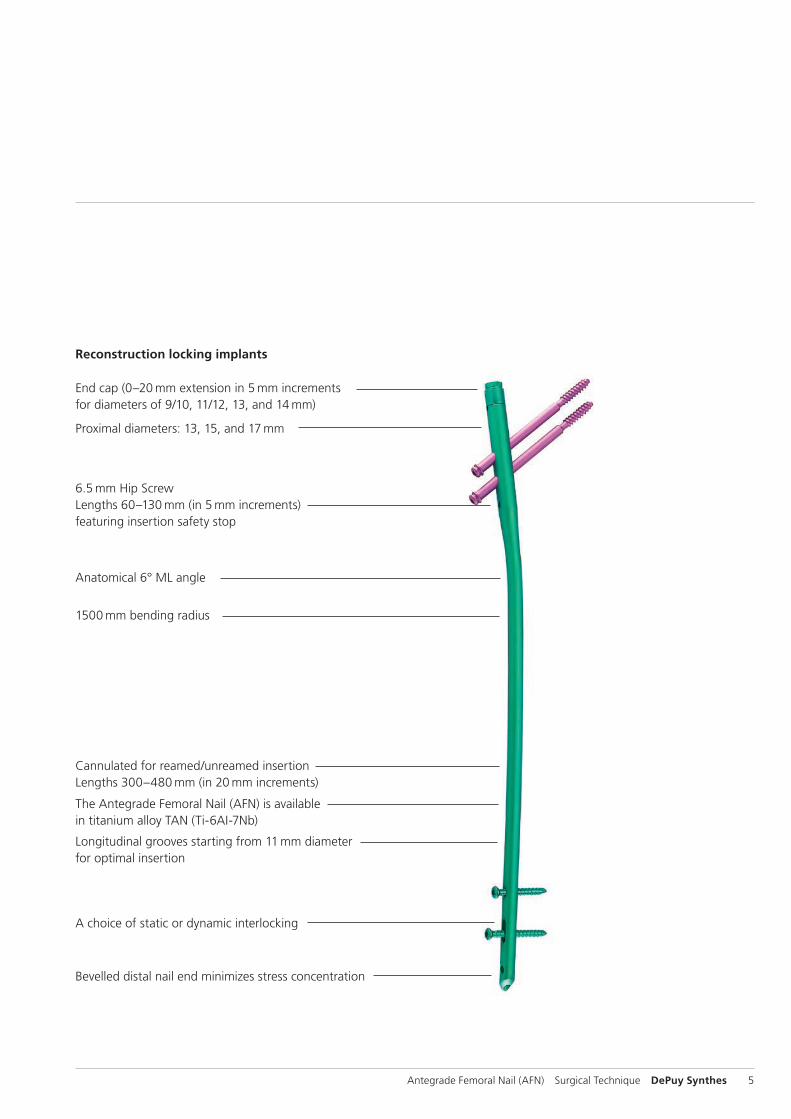
Reconstruction locking implants
End cap (0–20 mm extension in 5 mm increments for diameters of 9/10, 11/12, 13, and 14 mm)
6.5 mm Hip Screw Lengths 60–130 mm (in 5 mm increments) featuring insertion safety stop
Cannulated for reamed/unreamed insertion Lengths 300–480 mm (in 20 mm increments)
The Antegrade Femoral Nail (AFN) is available in titanium alloy TAN (Ti-6AI-7Nb)
Longitudinal grooves starting from 11 mm diameter for optimal insertion
Bevelled distal nail end minimizes stress concentration
A choice of static or dynamic interlocking
Proximal diameters: 13, 15, and 17 mm
Anatomical 6° ML angle
1500 mm bending radius
6 DePuy Synthes Antegrade Femoral Nail (AFN) Surgical Technique
Preparation
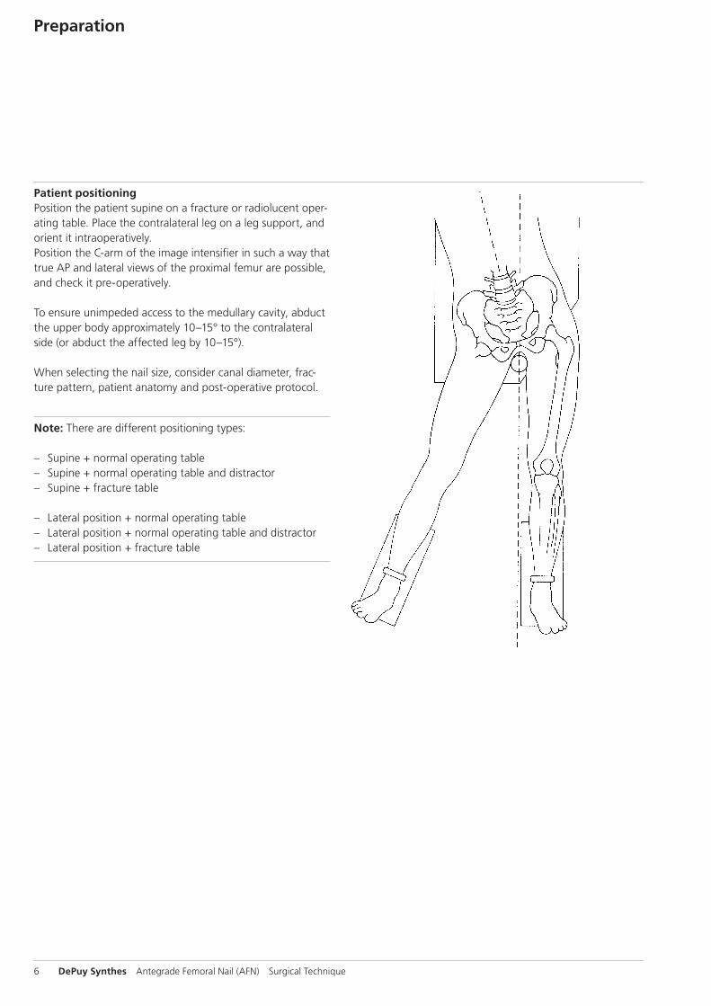
Patient positioningPosition the patient supine on a fracture or radiolucent oper-ating table. Place the contralateral leg on a leg support, and orient it intraoperatively. Position the C-arm of the image intensifier in such a way that true AP and lateral views of the proximal femur are possible, and check it pre-operatively.
To ensure unimpeded access to the medullary cavity, abduct the upper body approximately 10–15° to the contralateral side (or abduct the affect ed leg by 10–15°).
When selecting the nail size, consider canal diameter, frac-ture pattern, patient anatomy and post-operative protocol.
Note: There are different positioning types:
– Supine + normal operating table – Supine + normal operating table and distractor – Supine + fracture table
– Lateral position + normal operating table – Lateral position + normal operating table and distractor – Lateral position + fracture table
Antegrade Femoral Nail (AFN) Surgical Technique DePuy Synthes 7
Fracture reduction on the fracture tableIf possible, carry out a closed preoperative reduction of the fracture under image intensifier control. Exact reduction and secure fixation of the patient to the operating table are essential for easy handling and a good surgical result.
Use of the large distractor is also possible.
Use of the distractorThe application of the distractor can be helpful in many types of frac -tures, for old injuries, or when the assistants are inexperienced. Using standard techniques for applying the distractor, insert the distal Schanz screw laterally without image intensification at the level of the upper margin of the patella. The middle of the femur is easy to find with the drill bit. Insert the proximal Schanz screw under image intensifi-cation into the fe mur to allow the AFN to enter the medul-lary canal on the lateral side of the screw.
After mounting the connecting rods, distract the main frag-ments and achieve approximate reduction and length correc-tion. An alternative procedure involves inserting the proximal Schanz screw for the distraction from the lateral side. Place the distractor so that the nail can pass it easily during inser-tion.
8 DePuy Synthes Antegrade Femoral Nail (AFN) Surgical Technique
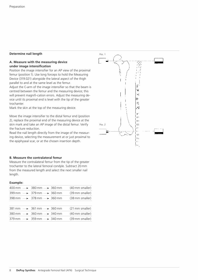
Determine nail length
A. Measure with the measuring device under image intensificationPosition the image intensifier for an AP view of the proximal femur (posi tion 1). Use long forceps to hold the Measuring Device (319.021) along side the lateral aspect of the thigh parallel to and at the same level as the femur. Adjust the C-arm of the image intensifier so that the beam is centred between the femur and the measuring device; this will prevent magnifi -ca tion errors. Adjust the measuring de-vice until its proximal end is level with the tip of the greater trochanter.Mark the skin at the top of the measuring device.
Move the image intensifier to the distal femur end (position 2), replace the proximal end of the measuring device at the skin mark and take an AP image of the distal femur. Verify the fracture reduction.Read the nail length directly from the image of the measur-ing device, selecting the measurement at or just proximal to the epiphyseal scar, or at the chosen insertion depth.
B. Measure the contralateral femurMeasure the contralateral femur from the tip of the greater trochanter to the lateral femoral condyle. Subtract 20 mm from the measured length and select the next smaller nail length.
Example:
400 mm 380 mm 360 mm (40 mm smaller)
399 mm 379 mm 360 mm (39 mm smaller)
398 mm 378 mm 360 mm (38 mm smaller)
381 mm 361 mm 360 mm (21 mm smaller)
380 mm 360 mm 340 mm (40 mm smaller)
379 mm 359 mm 340 mm (39 mm smaller)
Pos. 1
Pos. 2
Preparation
Antegrade Femoral Nail (AFN) Surgical Technique DePuy Synthes 9
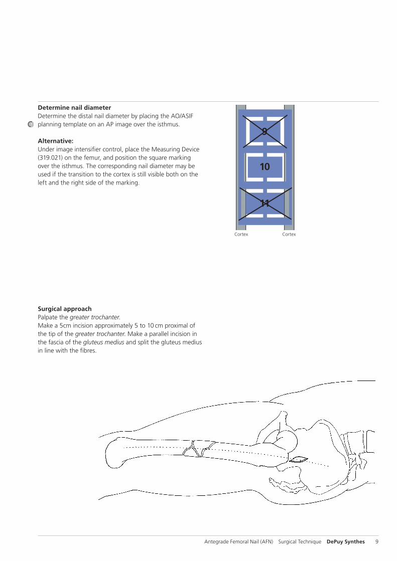
Determine nail diameterDetermine the distal nail diameter by placing the AO/ASIF planning template on an AP image over the isthmus.
Alternative:Under image intensifier control, place the Measuring Device (319.021) on the femur, and position the square marking over the isthmus. The corresponding nail diameter may be used if the tran sition to the cortex is still visible both on the left and the right side of the marking.
Surgical approachPalpate the greater trochanter.Make a 5cm incision approximately 5 to 10 cm proximal of the tip of the greater trochanter. Make a parallel incision in the fascia of the gluteus medius and split the gluteus medius in line with the fibres.
Cortex Cortex
9
10
11
P A
10 DePuy Synthes Antegrade Femoral Nail (AFN) Surgical Technique
Surgical technique for the AFN
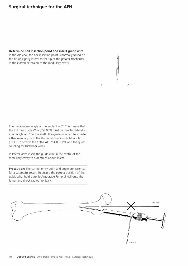
Determine nail insertion point and insert guide wireIn the AP view, the nail insertion point is normally found on the tip or slightly lateral to the tip of the greater trochanter in the curved extension of the medullary cavity.
The mediolateral angle of the implant is 6°. This means that the 2.8 mm Guide Wire (357.039) must be inserted laterally at an angle of 6° to the shaft. The guide wire can be inserted either manually with the Universal Chuck with T-Handle (393.100) or with the COMPACTTM AIR DRIVE and the quick coupling for Kirschner wires.
In lateral view, insert the guide wire in the centre of the medullary cavity to a depth of about 15 cm.
Precaution: The correct entry point and angle are essential for a successful result. To ensure the correct position of the guide wire, hold a sterile Antegrade Femoral Nail onto the femur and check radiographically.
correct
wrong
Antegrade Femoral Nail (AFN) Surgical Technique DePuy Synthes 11
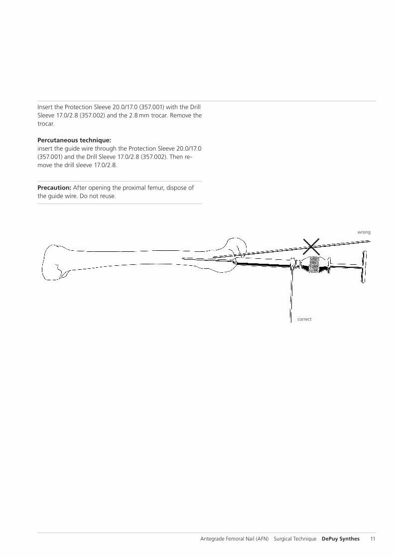
Insert the Protection Sleeve 20.0/17.0 (357.001) with the Drill Sleeve 17.0/2.8 (357.002) and the 2.8 mm trocar. Remove the trocar.
Percutaneous technique:insert the guide wire through the Protection Sleeve 20.0/17.0 (357.001) and the Drill Sleeve 17.0/2.8 (357.002). Then re-move the drill sleeve 17.0/2.8.
Precaution: After opening the proximal femur, dispose of the guide wire. Do not reuse.
correct
wrong
12 DePuy Synthes Antegrade Femoral Nail (AFN) Surgical Technique
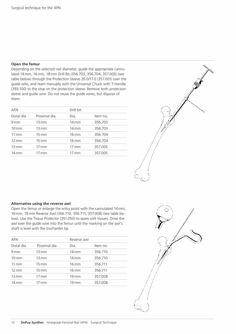
Open the femurDepending on the selected nail diameter, guide the appropriate cannu-lated 14 mm, 16 mm, 18 mm Drill Bit (356.703, 356.704, 357.005) (see table below) through the Protection Sleeve 20.0/17.0 (357.001) over the guide wire, and ream manually with the Universal Chuck with T-Handle (393.100) to the stop on the protection sleeve. Remove both protection sleeve and guide wire. Do not reuse the guide wires, but dispose of them.
AFN Drill bit
Distal dia. Proximal dia. Dia. Item no.
9 mm 13 mm 14 mm 356.703
10 mm 13 mm 14 mm 356.703
11 mm 15 mm 16 mm 356.704
12 mm 15 mm 16 mm 356.704
13 mm 17 mm 17 mm 357.005
14 mm 17 mm 17 mm 357.005
Alternative using the reverse awlOpen the femur or enlarge the entry point with the cannulated 14 mm, 16 mm, 18 mm Reverse Awl (356.710, 356.711, 357.008) (see table be-low). Use the Tissue Protector (351.050) to spare soft tissues. Drive the awl over the guide wire into the femur until the marking on the awl’s shaft is level with the trochanter tip.
AFN Reverse awl
Distal dia. Proximal dia. Dia. Item no.
9 mm 13 mm 14 mm 356.710
10 mm 13 mm 14 mm 356.710
11 mm 15 mm 16 mm 356.711
12 mm 15 mm 16 mm 356.711
13 mm 17 mm 19 mm 357.008
14 mm 17 mm 19 mm 357.008
Surgical technique for the AFN
Antegrade Femoral Nail (AFN) Surgical Technique DePuy Synthes 13
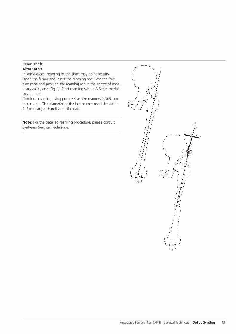
Ream shaftAlternativeIn some cases, reaming of the shaft may be necessary. Open the femur and insert the reaming rod. Pass the frac-ture zone and position the reaming rod in the centre of med-ullary cavity end (Fig. 1). Start reaming with a 8.5 mm medul-lary reamer. Continue reaming using progressive size reamers in 0.5 mm increments. The diameter of the last reamer used should be 1–2 mm larger than that of the nail.
Note: For the detailed reaming procedure, please consult SynReam Surgical Technique.
Fig. 2
Fig. 1
14 DePuy Synthes Antegrade Femoral Nail (AFN) Surgical Technique
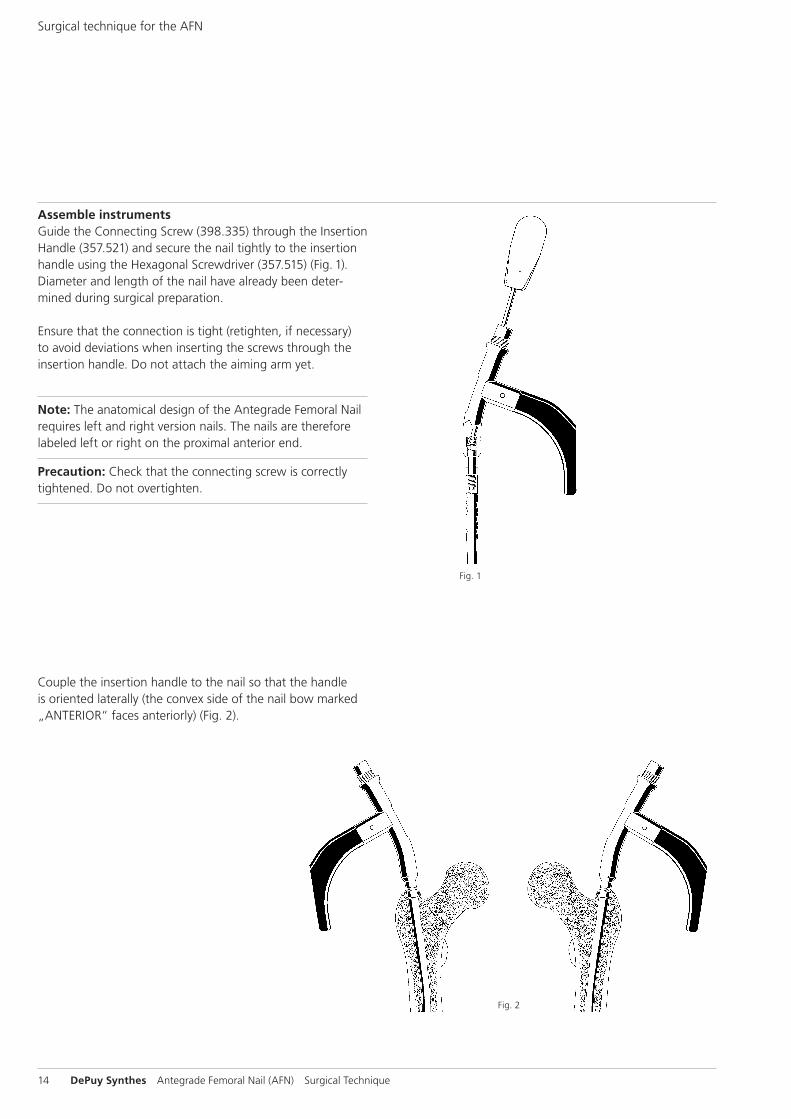
Assemble instrumentsGuide the Connecting Screw (398.335) through the Insertion Handle (357.521) and secure the nail tightly to the insertion handle using the Hexagonal Screwdriver (357.515) (Fig. 1).Diameter and length of the nail have already been deter-mined during surgical preparation.
Ensure that the connection is tight (retighten, if necessary) to avoid devi ations when inserting the screws through the insertion handle. Do not attach the aiming arm yet.
Note: The anatomical design of the Antegrade Femoral Nail requires left and right version nails. The nails are therefore labeled left or right on the proximal anterior end.
Precaution: Check that the connecting screw is correctly tightened. Do not overtighten.
Couple the insertion handle to the nail so that the handle is oriented laterally (the convex side of the nail bow marked „ANTERIOR“ faces anteriorly) (Fig. 2).
Fig. 1
Fig. 2
Surgical technique for the AFN
Antegrade Femoral Nail (AFN) Surgical Technique DePuy Synthes 15
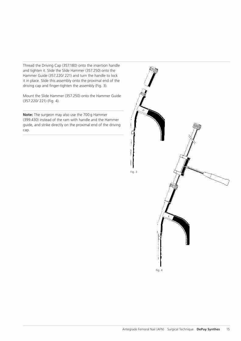
Fig. 4
Thread the Driving Cap (357.180) onto the insertion handle and tighten it. Slide the Slide Hammer (357.250) onto the Hammer Guide (357.220/ 221) and turn the handle to lock it in place. Slide this assembly onto the proximal end of the driving cap and finger-tighten the assembly (Fig. 3).
Mount the Slide Hammer (357.250) onto the Hammer Guide (357.220/ 221) (Fig. 4).
Note: The surgeon may also use the 700 g Hammer (399.430) instead of the ram with handle and the Hammer guide, and strike directly on the proximal end of the driving cap.
Fig. 3
16 DePuy Synthes Antegrade Femoral Nail (AFN) Surgical Technique
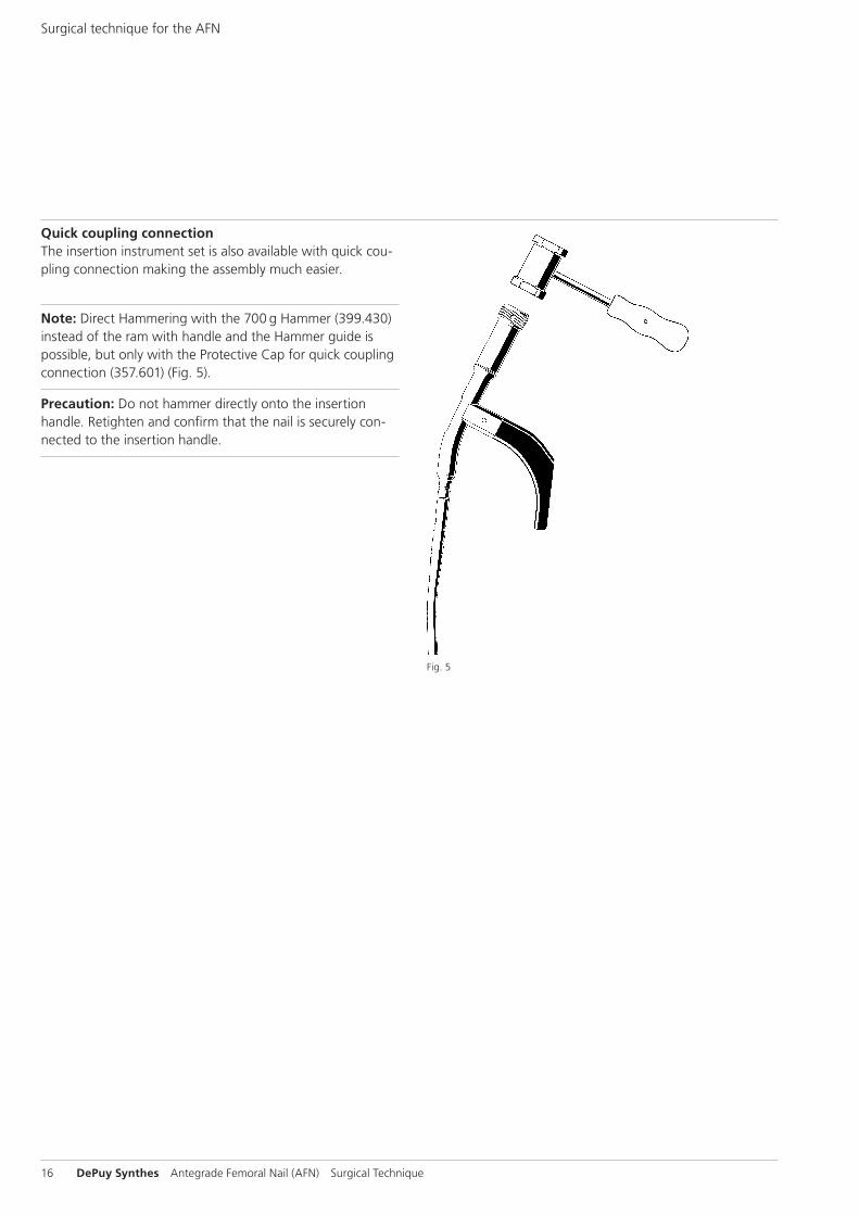
Quick coupling connectionThe insertion instrument set is also available with quick cou-pling connection making the assembly much easier.
Note: Direct Hammering with the 700 g Hammer (399.430) instead of the ram with handle and the Hammer guide is possible, but only with the Protective Cap for quick coupling connection (357.601) (Fig. 5).
Precaution: Do not hammer directly onto the insertion handle. Retighten and confirm that the nail is securely con-nected to the insertion handle.
Fig. 5
Surgical technique for the AFN
Antegrade Femoral Nail (AFN) Surgical Technique DePuy Synthes 17
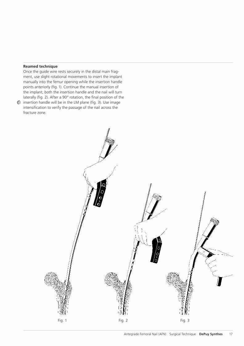
Reamed techniqueOnce the guide wire rests securely in the distal main frag-ment, use slight rotational movements to insert the implant manually into the femur opening while the insertion handle points anteriorly (fig. 1). Continue the manual insertion of the implant; both the insertion handle and the nail will turn laterally (fig. 2). After a 90° rotation, the final position of the insertion handle will be in the LM plane (fig. 3). Use image inten sification to verify the passage of the nail across the fracture zone.
Fig. 1 Fig. 2 Fig. 3
18 DePuy Synthes Antegrade Femoral Nail (AFN) Surgical Technique
Insert the nailUnreamed techniqueUse slight rotational movements to insert the nail manually into the femur opening while the insertion handle points an-teriorly. Push the implant manually to the fracture; both the insertion handle and the nail will turn laterally (compare illus-trations 1–3, page 18). Insert the guide wire. Reduce the fracture using the nail and the insertion handle, and guide the guide wire across the fracture line.
Verify the position of the guide wire in the distal fragment and correct it, if necessary. Advance the nail to the desired position.
Precaution: If nail insertion is difficult, choose a smaller diameter nail or ream the intramedullary canal to a larger diameter.
Use light Hammer blows to seat the nail into the metaphysis, leaving the proximal nail end at or just below the level of the tip of the greater troch anter. To avoid locking inaccuracies, recheck whether the connecting screw is secured tightly to the nail.
If nail over-insertion into the medullary cavity is required to ensure optimal positioning of the locking implants, the sur-geon may extend the nail length with an end cap (see page 34, insert the end cap).
Remove the guide wire.
Note: During insertion of a cannulated nail, the cannulated Coupling Shaft (357.516) may be used to retighten the connecting screw over the guide wire.
Surgical technique for the AFN
Antegrade Femoral Nail (AFN) Surgical Technique DePuy Synthes 19
Proximal locking
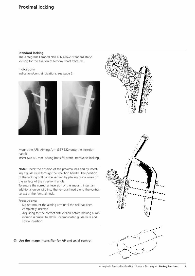
Standard lockingThe Antegrade Femoral Nail AFN allows standard static locking for the fixation of femoral shaft fractures
IndicationsIndications/contraindications, see page 2.
Mount the AFN Aiming Arm (357.522) onto the insertion handle.Insert two 4.9 mm locking bolts for static, transverse locking.
Note: Check the position of the proximal nail end by insert-ing a guide wire through the insertion handle. The position of the locking bolt can be verified by placing guide wires on the surface of the insertion handle. To ensure the correct anteversion of the implant, insert an additional guide wire into the femoral head along the ventral cortex of the femoral neck.
Precautions: – Do not mount the aiming arm until the nail has been
completely inserted. – Adjusting for the correct anteversion before making a skin
incision is crucial to allow uncomplicated guide wire and screw insertion.
Use the image intensifier for AP and axial control.
20 DePuy Synthes Antegrade Femoral Nail (AFN) Surgical Technique
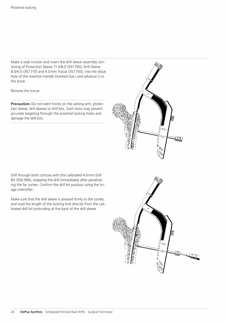
Make a stab incision and insert the drill sleeve assembly con-sisting of Protection Sleeve 11.0/8.0 (357.760), Drill Sleeve 8.0/4.0 (357.710) and 4.0 mm Trocar (357.750), into the distal hole of the insertion handle (marked stat.) and advance it to the bone.
Remove the trocar.
Precaution: Do not exert forces on the aiming arm, protec-tion sleeve, drill sleeves or drill bits. Such force may prevent accurate targeting through the proximal locking holes and damage the drill bits.
Drill through both cortices with the calibrated 4.0 mm Drill Bit (356.980), stopping the drill immediately after penetrat-ing the far cortex. Confirm the drill bit position using the im-age intensifier.
Make sure that the drill sleeve is pressed firmly to the cortex, and read the length of the locking bolt directly from the cali-brated drill bit protruding at the back of the drill sleeve.
Proximal locking
Antegrade Femoral Nail (AFN) Surgical Technique DePuy Synthes 21
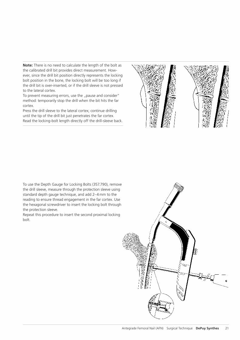
To use the Depth Gauge for Locking Bolts (357.790), remove the drill sleeve, measure through the protection sleeve using standard depth gauge technique, and add 2–4 mm to the reading to ensure thread engagement in the far cortex. Use the hexagonal screwdriver to insert the locking bolt through the protection sleeve. Repeat this procedure to insert the second proximal locking bolt.
Note: There is no need to calculate the length of the bolt as the calibrated drill bit provides direct measurement. How-ever, since the drill bit position directly represents the locking bolt position in the bone, the locking bolt will be too long if the drill bit is over-inserted, or if the drill sleeve is not pressed to the lateral cortex. To prevent measuring errors, use the „pause and consider“ method: temporarily stop the drill when the bit hits the far cortex. Press the drill sleeve to the lateral cortex; continue drilling until the tip of the drill bit just penetrates the far cortex. Read the locking-bolt length directly off the drill-sleeve back.
22 DePuy Synthes Antegrade Femoral Nail (AFN) Surgical Technique
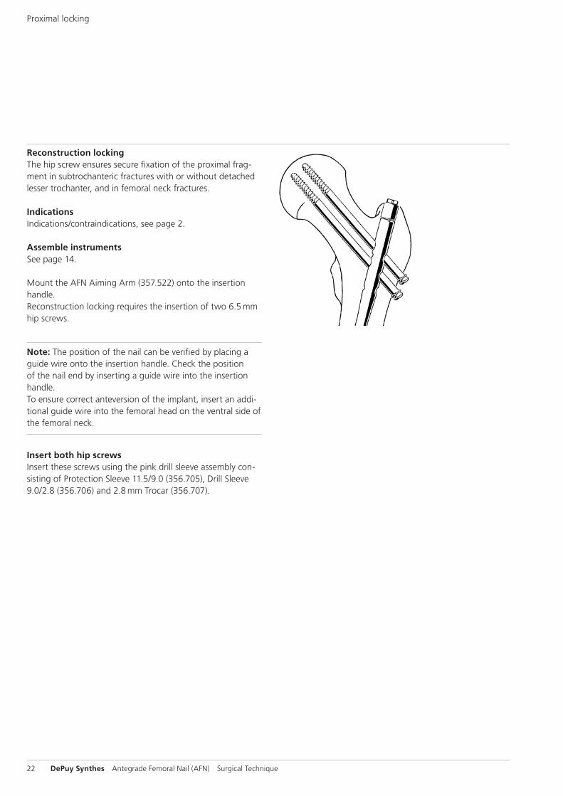
Reconstruction lockingThe hip screw ensures secure fixation of the proximal frag-ment in sub trochanteric fractures with or without detached lesser trochanter, and in femoral neck fractures.
IndicationsIndications/contraindications, see page 2.
Assemble instrumentsSee page 14.
Mount the AFN Aiming Arm (357.522) onto the insertion handle.Reconstruction locking requires the insertion of two 6.5 mm hip screws.
Note: The position of the nail can be verified by placing a guide wire onto the insertion handle. Check the position of the nail end by inserting a guide wire into the insertion handle. To ensure correct anteversion of the implant, insert an addi-tional guide wire into the femoral head on the ventral side of the femoral neck.
Insert both hip screwsInsert these screws using the pink drill sleeve assembly con-sisting of Protection Sleeve 11.5/9.0 (356.705), Drill Sleeve 9.0/2.8 (356.706) and 2.8 mm Trocar (356.707).
Proximal locking
Antegrade Femoral Nail (AFN) Surgical Technique DePuy Synthes 23
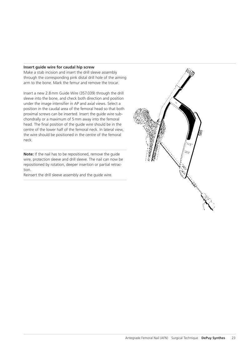
Insert guide wire for caudal hip screwMake a stab incision and insert the drill sleeve assembly through the corresponding pink distal drill hole of the aiming arm to the bone. Mark the femur and remove the trocar.
Insert a new 2.8 mm Guide Wire (357.039) through the drill sleeve into the bone, and check both direction and position under the image intensifier in AP and axial views. Select a position in the caudal area of the fe mo ral head so that both proximal screws can be inserted. Insert the guide wire sub-chondrally or a maximum of 5 mm away into the femoral head. The final position of the guide wire should be in the centre of the lower half of the femoral neck. In lateral view, the wire should be positioned in the centre of the femoral neck.
Note: If the nail has to be repositioned, remove the guide wire, protection sleeve and drill sleeve. The nail can now be repositioned by rotation, deeper insertion or partial retrac-tion. Reinsert the drill sleeve assembly and the guide wire.
24 DePuy Synthes Antegrade Femoral Nail (AFN) Surgical Technique
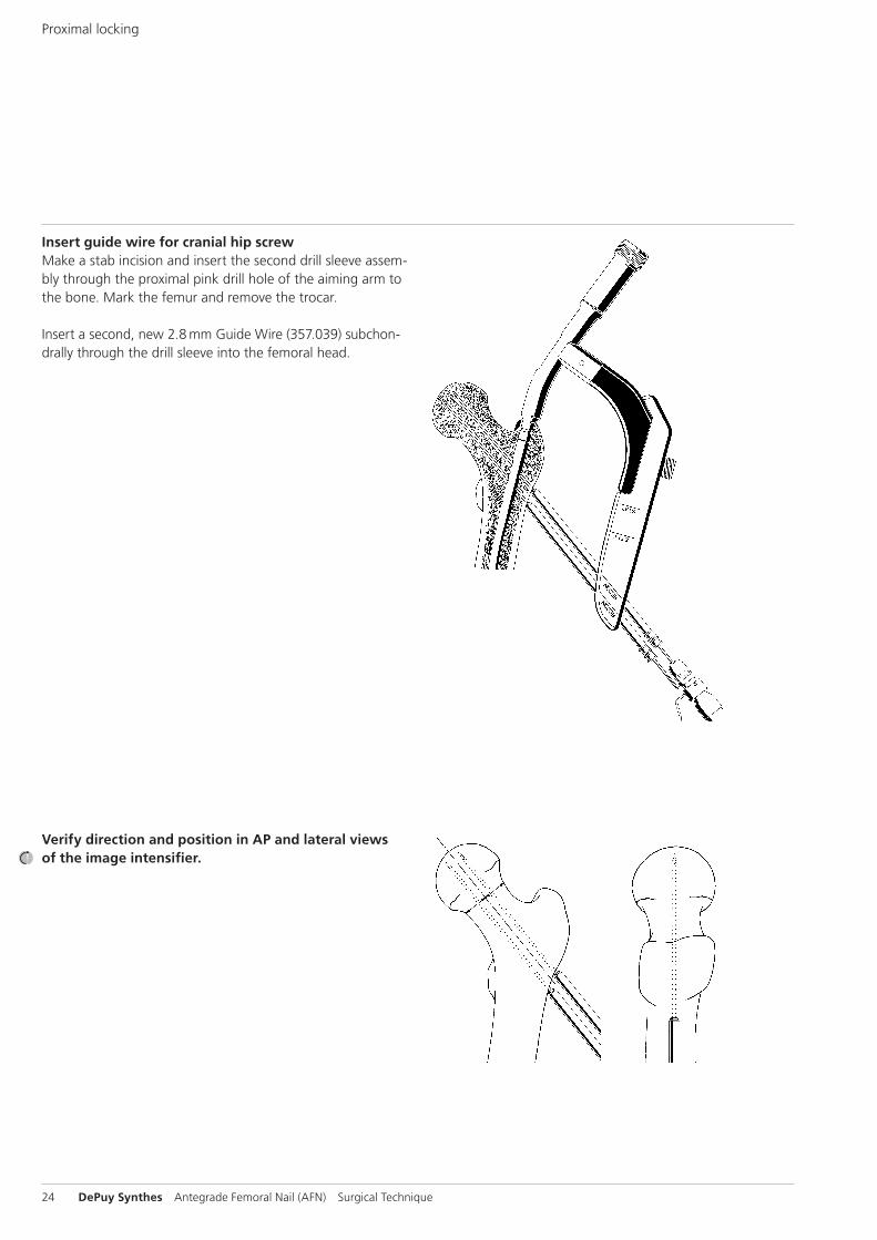
Insert guide wire for cranial hip screwMake a stab incision and insert the second drill sleeve assem-bly through the proximal pink drill hole of the aiming arm to the bone. Mark the femur and remove the trocar.
Insert a second, new 2.8 mm Guide Wire (357.039) subchon-drally through the drill sleeve into the femoral head.
Verify direction and position in AP and lateral views of the image intensifier.
Proximal locking
Antegrade Femoral Nail (AFN) Surgical Technique DePuy Synthes 25
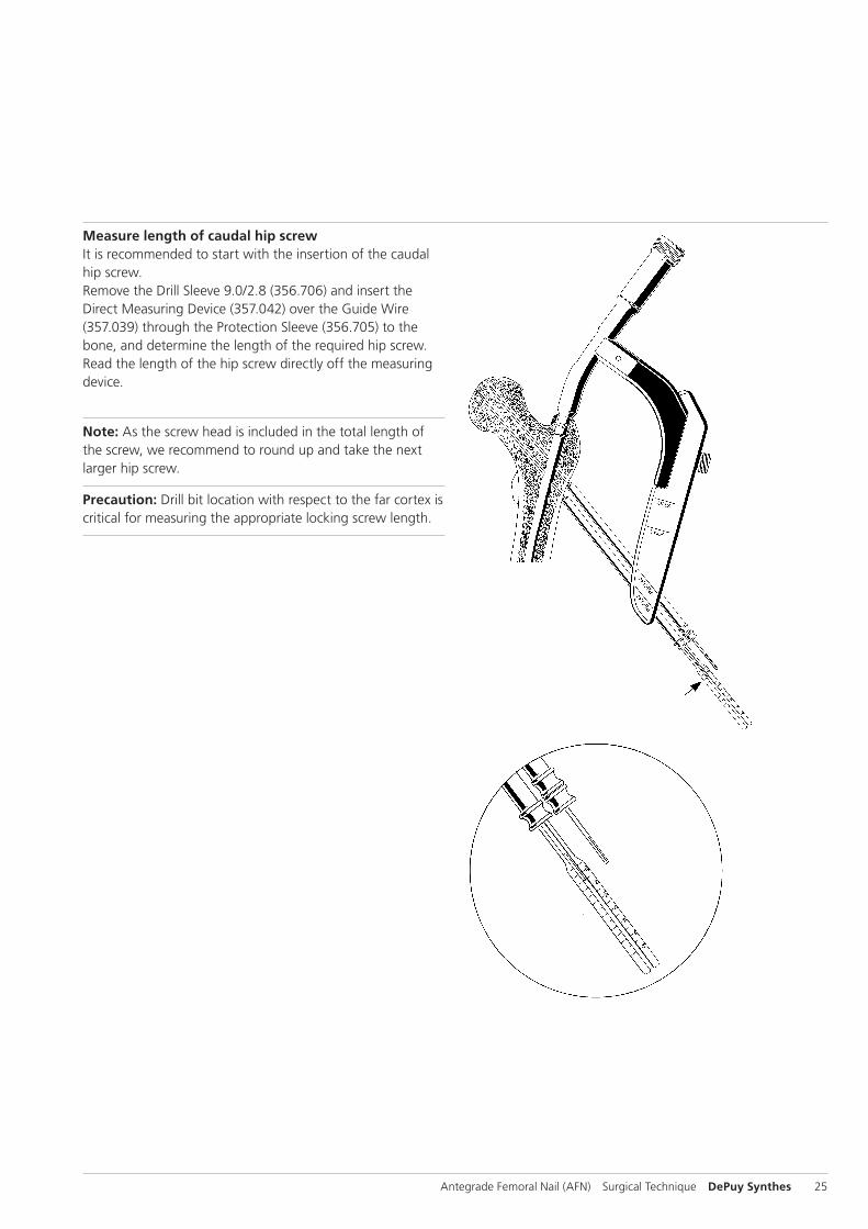
Measure length of caudal hip screwIt is recommended to start with the insertion of the caudal hip screw.Remove the Drill Sleeve 9.0/2.8 (356.706) and insert the Direct Measuring Device (357.042) over the Guide Wire (357.039) through the Protection Sleeve (356.705) to the bone, and determine the length of the required hip screw. Read the length of the hip screw directly off the measuring device.
Note: As the screw head is included in the total length of the screw, we recommend to round up and take the next larger hip screw.
Precaution: Drill bit location with respect to the far cortex is critical for measuring the appropriate locking screw length.
26 DePuy Synthes Antegrade Femoral Nail (AFN) Surgical Technique
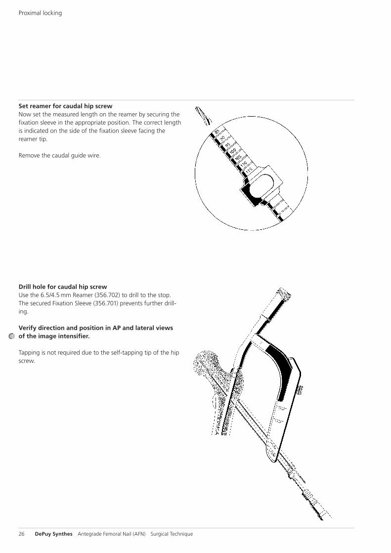
Set reamer for caudal hip screwNow set the measured length on the reamer by securing the fixation sleeve in the appropriate position. The correct length is indicated on the side of the fixation sleeve facing the reamer tip.
Remove the caudal guide wire.
Drill hole for caudal hip screwUse the 6.5/4.5 mm Reamer (356.702) to drill to the stop. The secured Fixation Sleeve (356.701) prevents further drill-ing.
Verify direction and position in AP and lateral views of the image intensifier.
Tapping is not required due to the self-tapping tip of the hip screw.
Proximal locking
Antegrade Femoral Nail (AFN) Surgical Technique DePuy Synthes 27
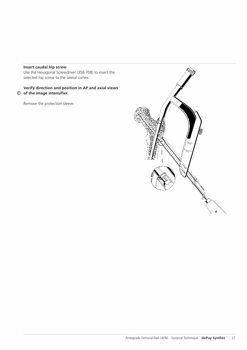
Insert caudal hip screwUse the Hexagonal Screwdriver (356.708) to insert the selected hip screw to the lateral cortex.
Verify direction and position in AP and axial views of the image intensifier.
Remove the protection sleeve.
28 DePuy Synthes Antegrade Femoral Nail (AFN) Surgical Technique
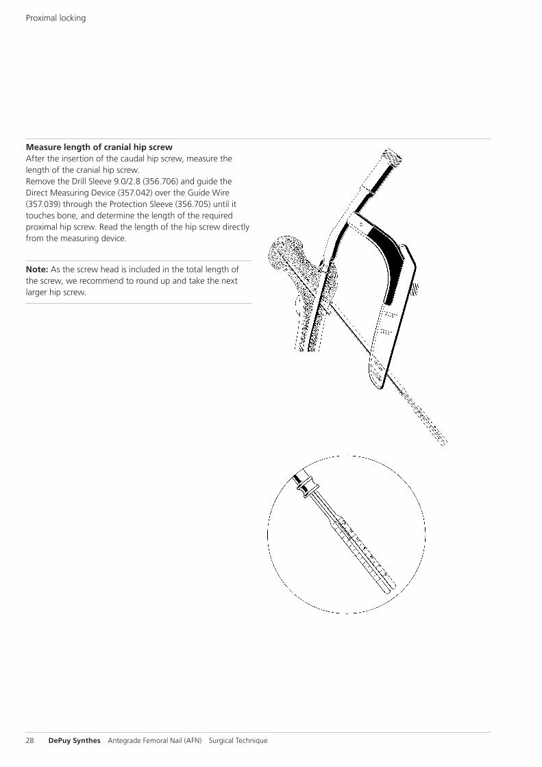
Measure length of cranial hip screwAfter the insertion of the caudal hip screw, measure the length of the cranial hip screw.Remove the Drill Sleeve 9.0/2.8 (356.706) and guide the Direct Measuring Device (357.042) over the Guide Wire (357.039) through the Protection Sleeve (356.705) until it touches bone, and determine the length of the required proximal hip screw. Read the length of the hip screw directly from the measuring device.
Note: As the screw head is included in the total length of the screw, we recommend to round up and take the next larger hip screw.
Proximal locking
Antegrade Femoral Nail (AFN) Surgical Technique DePuy Synthes 29
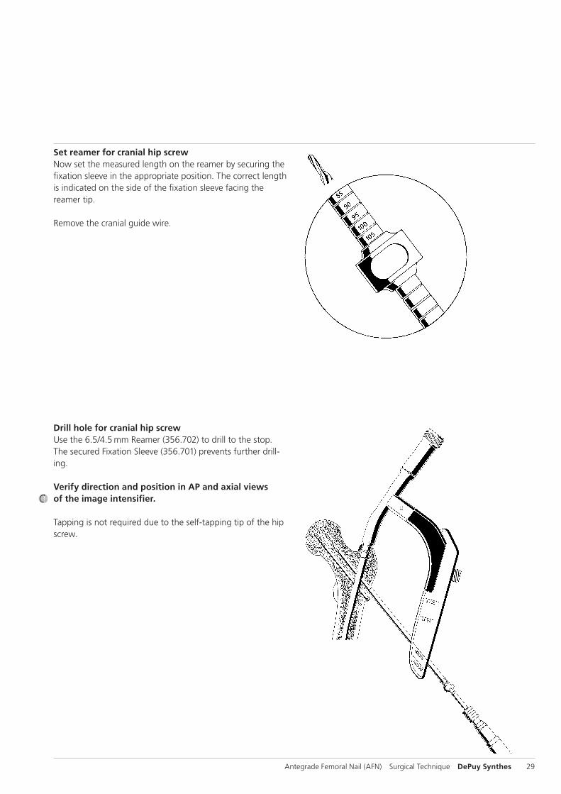
Set reamer for cranial hip screwNow set the measured length on the reamer by securing the fixation sleeve in the appropriate position. The correct length is indicated on the side of the fixation sleeve facing the reamer tip.
Remove the cranial guide wire.
Drill hole for cranial hip screwUse the 6.5/4.5 mm Reamer (356.702) to drill to the stop. The secured Fixation Sleeve (356.701) prevents further drill-ing.
Verify direction and position in AP and axial views of the image intensifier.
Tapping is not required due to the self-tapping tip of the hip screw.
30 DePuy Synthes Antegrade Femoral Nail (AFN) Surgical Technique
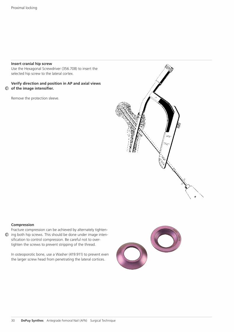
Insert cranial hip screwUse the Hexagonal Screwdriver (356.708) to insert the selected hip screw to the lateral cortex.
Verify direction and position in AP and axial views of the image intensifier.
Remove the protection sleeve.
CompressionFracture compression can be achieved by alternately tighten-ing both hip screws. This should be done under image inten-sification to control compression. Be careful not to over-tighten the screws to prevent stripping of the thread.
In osteoporotic bone, use a Washer (419.911) to prevent even the larger screw head from penetrating the lateral cortices.
Proximal locking
Antegrade Femoral Nail (AFN) Surgical Technique DePuy Synthes 31
Distal locking
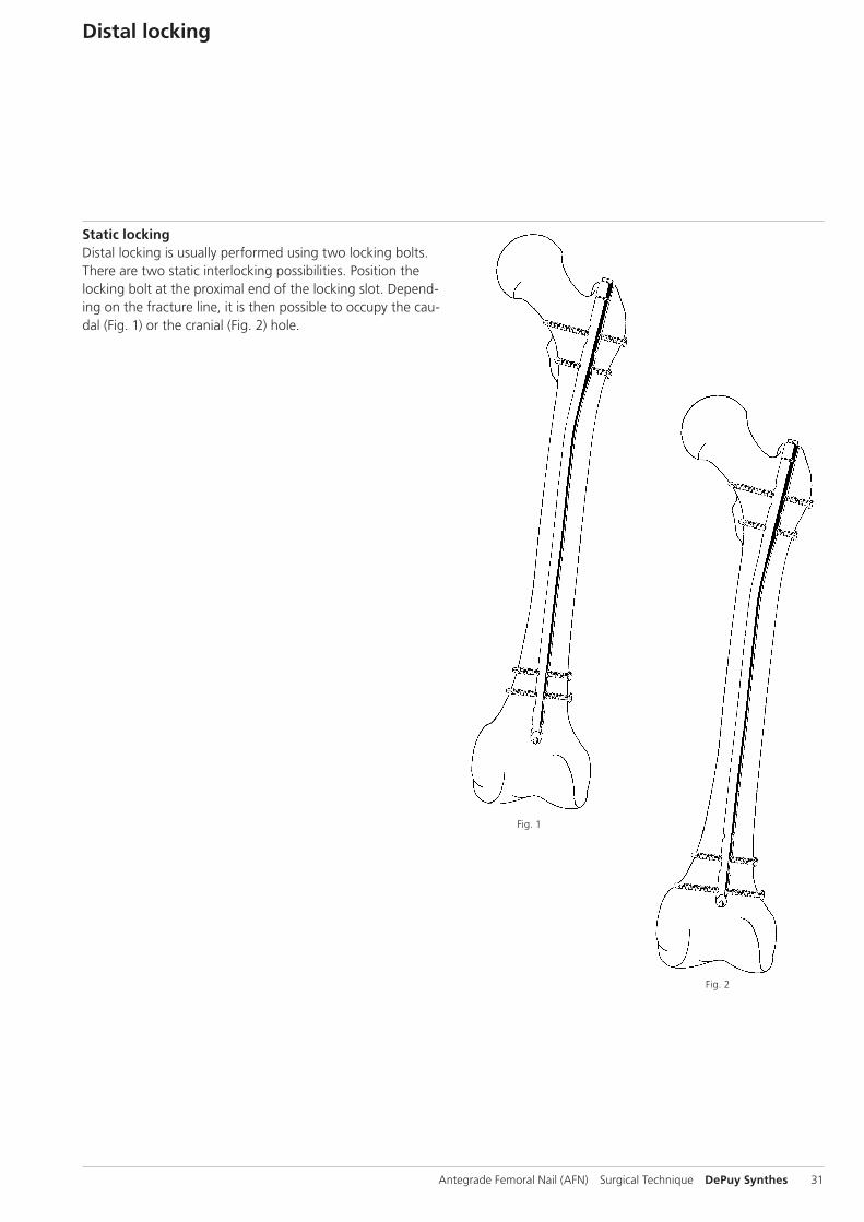
Static lockingDistal locking is usually performed using two locking bolts.There are two static interlocking possibilities. Position the locking bolt at the proximal end of the locking slot. Depend-ing on the fracture line, it is then possible to occupy the cau-dal (Fig. 1) or the cranial (Fig. 2) hole.
Fig. 1
Fig. 2
32 DePuy Synthes Antegrade Femoral Nail (AFN) Surgical Technique
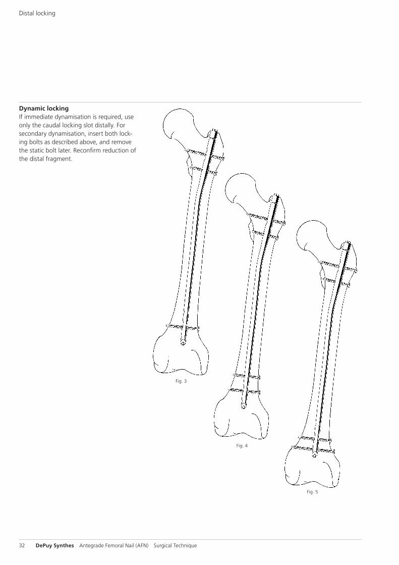
Dynamic lockingIf immediate dynamisation is required, use only the caudal locking slot distally. For secondary dynamisation, insert both lock-ing bolts as described above, and remove the static bolt later. Reconfirm reduction of the distal fragment.
Fig. 3
Fig. 4
Fig. 5
Distal locking
Antegrade Femoral Nail (AFN) Surgical Technique DePuy Synthes 33
Note: In dynamisation, there is a risk of the nail penetrating the knee, due to the somewhat deeper position of the nail in reconstruction locking.
Use the Radiolucent Drive Mark II: align the image intensifier with the nail hole to be drilled until a perfect circle is visible in the centre of the screen. Make a stab incision at the inci-sion point.
Use image intensifier control to insert the tip of the Drill Bit (356.980) into the incision, and hold the drill bit oblique to the X-ray beam until the tip is centred in the locking slot. Tilt the drive until the drill bit is in line with the beam and appears as a radio-opaque, solid circle in the centre of the outer ring. The drill bit will nearly fill the locking-hole image. Hold the drill bit in this position and drill through both corti-ces. Measure the required locking bolt length using the Depth Gauge for Locking Bolts (357.790) adding 2–4 mm to the read ing to ensure locking bolt engagement in the far cortex.
Use the large Hexagonal Screwdriver (356.708) to insert the bolt.Repeat the procedure for the second distal locking bolt. For static interlocking, position the caudal bolt at the proximal end of the locking slot, for dynamic interlocking at the distal end of the locking slot to allow dynamisation.
Verify direction and position in AP and axial views of the image intensifier.
Note: If the Radiolucent Drive MARK II is not available, per-form distal locking in standard freehand technique using the Drill Bit (356.980).
34 DePuy Synthes Antegrade Femoral Nail (AFN) Surgical Technique
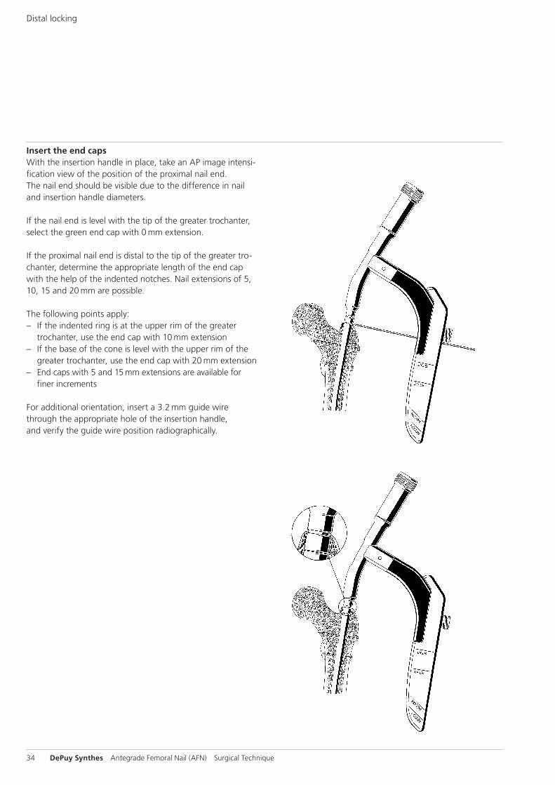
Insert the end capsWith the insertion handle in place, take an AP image intensi-fication view of the position of the proximal nail end. The nail end should be visible due to the difference in nail and insertion handle diameters.
If the nail end is level with the tip of the greater trochanter, select the green end cap with 0 mm extension.
If the proximal nail end is distal to the tip of the greater tro-chanter, determine the appropriate length of the end cap with the help of the indented notches. Nail extensions of 5, 10, 15 and 20 mm are possible.
The following points apply: – If the indented ring is at the upper rim of the greater
trochanter, use the end cap with 10 mm extension – If the base of the cone is level with the upper rim of the
greater trochanter, use the end cap with 20 mm extension – End caps with 5 and 15 mm extensions are available for
finer increments
For additional orientation, insert a 3.2 mm guide wire through the appro priate hole of the insertion handle, and verify the guide wire position radiographically.
Distal locking
Antegrade Femoral Nail (AFN) Surgical Technique DePuy Synthes 35
Loosen the connecting screw and remove the insertion handle.
Insert the hook of the Guide Wire with Hook (356.717) through the selected end cap. Now guide the 11/11 mm Cannulated Hexagonal Socket (356.715) over the guide wire to the end cap. The end cap is automat i cally secured as soon as this connection is made.
Guide the cannulated end cap to the proximal end of the nail. Tighten the end cap using the 11 mm Ratchet Wrench (321.200). Fully insert the end cap into the nail.
As the final threads of the end cap turn into the nail, you will feel increased resistance. Continue turning until the shoulder of the end cap contacts the proximal nail end. This prevents backout.
Notes: – If the indented ring is level with the upper rim of the
greater trochanter, use the end cap with 10 mm extension – If the base of the cone is level with the upper rim of the
greater trochanter, use the end cap with 20 mm extension
Remove the hexagonal socket, the ratchet wrench and the guide wire.
36 DePuy Synthes Antegrade Femoral Nail (AFN) Surgical Technique
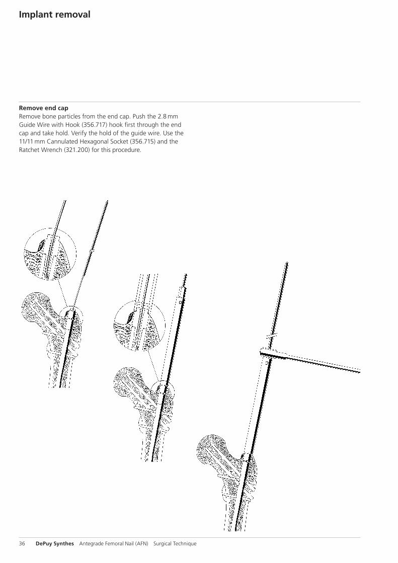
Implant removal
Remove end capRemove bone particles from the end cap. Push the 2.8 mm Guide Wire with Hook (356.717) hook first through the end cap and take hold. Verify the hold of the guide wire. Use the 11/11 mm Cannulated Hexagonal Socket (356.715) and the Ratchet Wrench (321.200) for this procedure.
Antegrade Femoral Nail (AFN) Surgical Technique DePuy Synthes 37
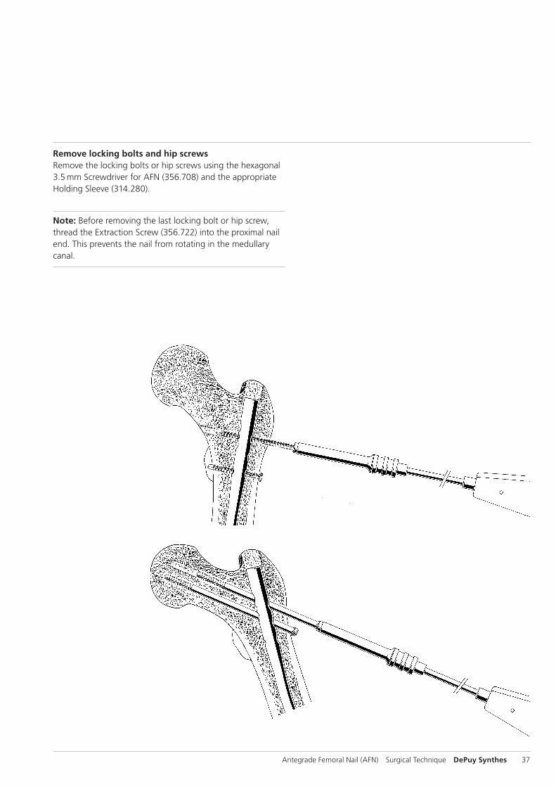
Remove locking bolts and hip screwsRemove the locking bolts or hip screws using the hexagonal 3.5 mm Screw driver for AFN (356.708) and the appropriate Holding Sleeve (314.280).
Note: Before removing the last locking bolt or hip screw, thread the Extraction Screw (356.722) into the proximal nail end. This prevents the nail from rotating in the medullary canal.
38 DePuy Synthes Antegrade Femoral Nail (AFN) Surgical Technique
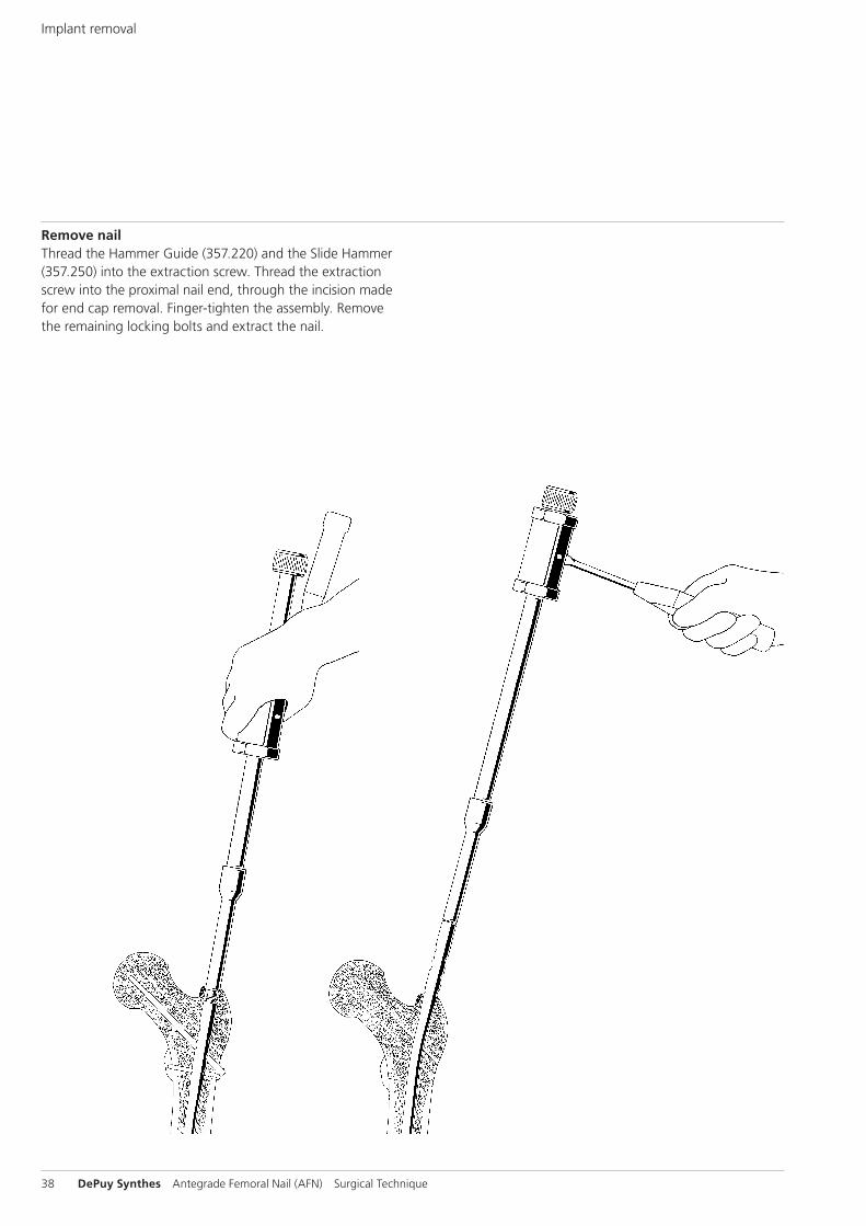
Remove nailThread the Hammer Guide (357.220) and the Slide Hammer (357.250) into the extraction screw. Thread the extraction screw into the proximal nail end, through the incision made for end cap removal. Finger-tighten the assembly. Remove the remaining locking bolts and extract the nail.
Implant removal
Instruments
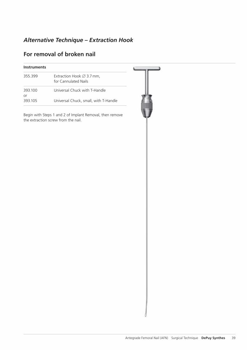
355.399 Extraction Hook B 3.7 mm, for Cannulated Nails
393.100 Universal Chuck with T-Handle or393.105 Universal Chuck, small, with T-Handle
Begin with Steps 1 and 2 of Implant Removal, then remove the extraction screw from the nail.
Antegrade Femoral Nail (AFN) Surgical Technique DePuy Synthes 39
Alternative Technique – Extraction Hook
For removal of broken nail
Option 1
1Assemble extraction hook and universal chuck
Insert the extraction hook into the universal chuck with T-handle. The hook should be parallel with the T-handle. This facilitates visualization of the hook position in the bone.
2Insert extraction hook through nail
Pass the extraction hook through the cannula of the nail, including the distant fragment.
Precaution: Under image intensification, verify that the hook has passed through and engaged the distant end of the nail.
3Extract nail
Extract both nail fragments.
Note: Keep the patient’s limb restrained to increase the effi-ciency of the extraction force.
Implant Removal
40 DePuy Synthes Antegrade Femoral Nail (AFN) Surgical Technique
Option 2
1Remove near nail fragment
Attach the appropriate extraction bolt or extraction screw to the nail. Remove the near nail fragment using the extraction bolt or extraction screw.
Note: The extraction hook can be used as an alternative to extraction instrumentation.
2Ream canal
Ream the medullary canal 1 mm larger than the nail diameter to clear a path for the distant nail fragment.
3Align extraction hook
Insert the extraction hook and explanted near nail fragment into the medullary canal. The near nail fragment aligns the extraction hook with the cannulation of the distant nail fragment.
Antegrade Femoral Nail (AFN) Surgical Technique DePuy Synthes 41

4Engage distant fragment
Pass the extraction hook through the cannula of the distant nail fragment.
Precaution: Under image intensifi cation, verify that the hook has passed through and engaged the distant end of the nail.
5Extract nail
Extract both nail fragments.
Note: Keep the patient’s limb restrained to increase the effi ciency of the extraction force.
Implant Removal
42 DePuy Synthes Antegrade Femoral Nail (AFN) Surgical Technique

Antegrade Femoral Nail (AFN) Surgical Technique DePuy Synthes 43
Cleaning
Intra-operative and postoperative cleaningUse the 2.8 mm Stylet (319.460) to clean the cannulations of the instruments intraoperatively.
Subject to alterations.
44 DePuy Synthes Antegrade Femoral Nail (AFN) Surgical Technique
Implants
Hip Screws
418.260 418.260S Hip Screw B 6.5 mm for AFN, self-tapping, length 60 mm, Titanium Alloy (TAN)
418.265 418.265S Hip Screw B 6.5 mm for AFN, self-tapping, length 65 mm, Titanium Alloy (TAN)
418.270 418.270S Hip Screw B 6.5 mm for AFN, self-tapping, length 70 mm, Titanium Alloy (TAN)
418.275 418.275S Hip Screw B 6.5 mm for AFN, self-tapping, length 75 mm, Titanium Alloy (TAN)
418.280 418.280S Hip Screw B 6.5 mm for AFN, self-tapping, length 80 mm, Titanium Alloy (TAN)
418.285 418.285S Hip Screw B 6.5 mm for AFN, self-tapping, length 85 mm, Titanium Alloy (TAN)
418.290 418.290S Hip Screw B 6.5 mm for AFN, self-tapping, length 90 mm, Titanium Alloy (TAN)
418.295 418.295S Hip Screw B 6.5 mm for AFN, self-tapping, length 95 mm, Titanium Alloy (TAN)
418.300 418.300S Hip Screw B 6.5 mm for AFN, self-tapping, length 100 mm, Titanium Alloy (TAN)
418.305 418.305S Hip Screw B 6.5 mm for AFN, self-tapping, length 105 mm, Titanium Alloy (TAN)
418.310 418.310S Hip Screw B 6.5 mm for AFN, self-tapping, length 110 mm, Titanium Alloy (TAN)
418.315 418.315S Hip Screw B 6.5 mm for AFN, self-tapping, length 115 mm, Titanium Alloy (TAN)
418.320 418.320S Hip Screw B 6.5 mm for AFN, self-tapping, length 120 mm, Titanium Alloy (TAN)
418.325 418.325S Hip Screw B 6.5 mm for AFN, self-tapping, length 125 mm, Titanium Alloy (TAN)
418.330 418.330S Hip Screw B 6.5 mm for AFN, self-tapping, length 130 mm, Titanium Alloy (TAN)
Antegrade Femoral Nail (AFN) Surgical Technique DePuy Synthes 45
Washer
419.911 419.911S Washer B 12.5/6.5 mm, thickness 2.5 mm, Titanium Alloy (TAN)
End Caps
418.360 418.360S End Cap for AFN B 9.0–10.0 mm, cannulated, extension 0 mm
418.361 418.361S End Cap for AFN B 9.0–10.0 mm, cannulated, extension 5 mm
418.362 418.362S End Cap for AFN B 9.0–10.0 mm, cannulated, extension 10 mm
418.363 418.363S End Cap for AFN B 9.0–10.0 mm, cannulated, extension 15 mm
418.364 418.364S End Cap for AFN B 9.0–10.0 mm, cannulated, extension 20 mm
418.370 418.370S End Cap for AFN B 11.0–12.0 mm, cannulated, extension 0 mm
418.371 418.371S End Cap for AFN B 11.0–12.0 mm, cannulated, extension 5 mm, sterile
418.372 418.372S End Cap for AFN B 11.0–12.0 mm, cannulated, extension 10 mm, sterile
418.373 418.373S End Cap for AFN B 11.0–12.0 mm, cannulated, extension 15 mm
418.374 418.374S End Cap for AFN B 11.0–12.0 mm, cannulated, extension 20 mm
418.380 418.380S End Cap for AFN B 13.0–14.0 mm, cannulated, extension 0 mm
418.381 418.381S End Cap for AFN B 13.0–14.0 mm, cannulated, extension 5 mm
418.382 418.382S End Cap for AFN B 13.0–14.0 mm, cannulated, extension 10 mm
418.383 418.383S End Cap for AFN B 13.0–14.0 mm, cannulated, extension 15 mm
418.384 418.384S End Cap for AFN B 13.0–14.0 mm, cannulated, extension 20 mm
46 DePuy Synthes Antegrade Femoral Nail (AFN) Surgical Technique
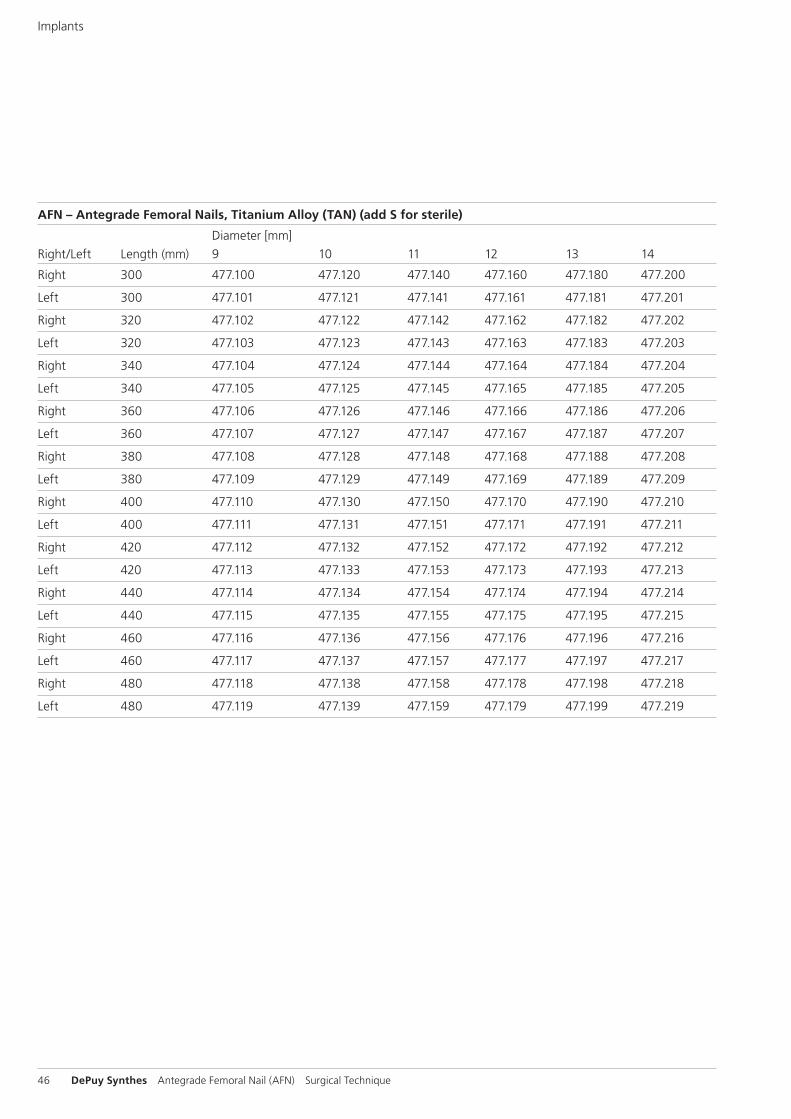
AFN – Antegrade Femoral Nails, Titanium Alloy (TAN) (add S for sterile)
Diameter [mm]Right/Left Length (mm) 9 10 11 12 13 14
Right 300 477.100 477.120 477.140 477.160 477.180 477.200
Left 300 477.101 477.121 477.141 477.161 477.181 477.201
Right 320 477.102 477.122 477.142 477.162 477.182 477.202
Left 320 477.103 477.123 477.143 477.163 477.183 477.203
Right 340 477.104 477.124 477.144 477.164 477.184 477.204
Left 340 477.105 477.125 477.145 477.165 477.185 477.205
Right 360 477.106 477.126 477.146 477.166 477.186 477.206
Left 360 477.107 477.127 477.147 477.167 477.187 477.207
Right 380 477.108 477.128 477.148 477.168 477.188 477.208
Left 380 477.109 477.129 477.149 477.169 477.189 477.209
Right 400 477.110 477.130 477.150 477.170 477.190 477.210
Left 400 477.111 477.131 477.151 477.171 477.191 477.211
Right 420 477.112 477.132 477.152 477.172 477.192 477.212
Left 420 477.113 477.133 477.153 477.173 477.193 477.213
Right 440 477.114 477.134 477.154 477.174 477.194 477.214
Left 440 477.115 477.135 477.155 477.175 477.195 477.215
Right 460 477.116 477.136 477.156 477.176 477.196 477.216
Left 460 477.117 477.137 477.157 477.177 477.197 477.217
Right 480 477.118 477.138 477.158 477.178 477.198 477.218
Left 480 477.119 477.139 477.159 477.179 477.199 477.219
Implants
Antegrade Femoral Nail (AFN) Surgical Technique DePuy Synthes 47
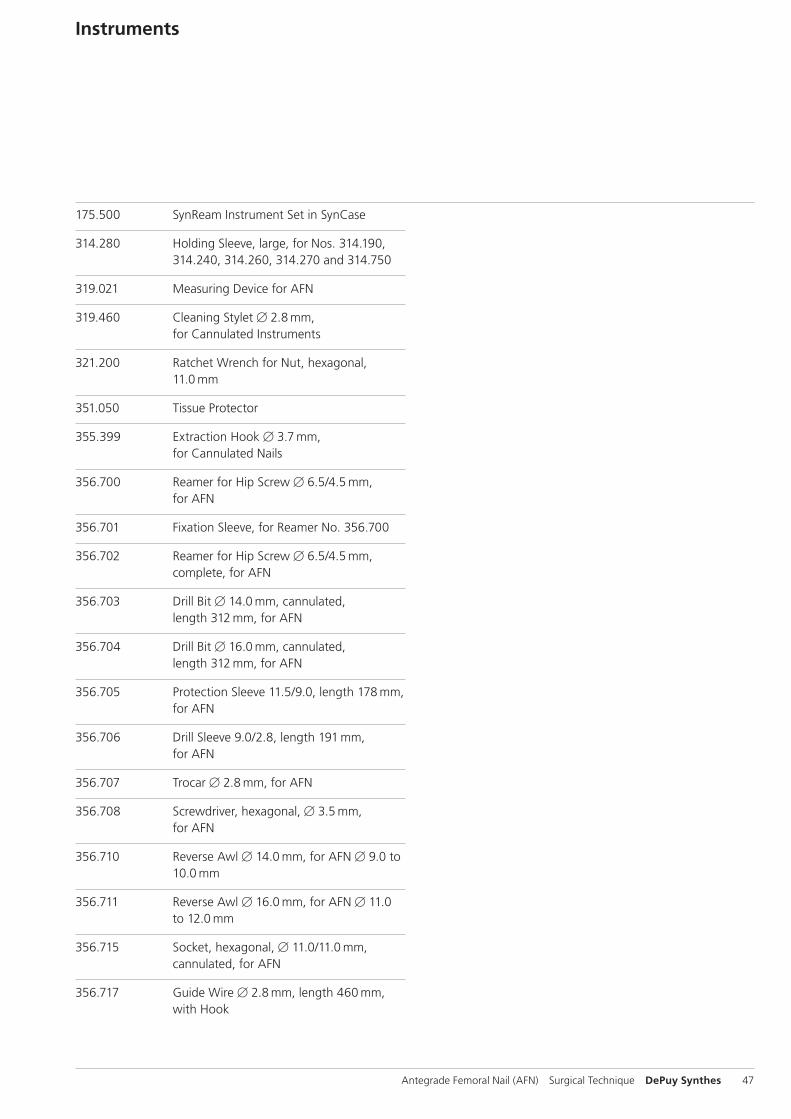
175.500 SynReam Instrument Set in SynCase
314.280 Holding Sleeve, large, for Nos. 314.190, 314.240, 314.260, 314.270 and 314.750
319.021 Measuring Device for AFN
319.460 Cleaning Stylet B 2.8 mm, for Cannulated Instruments
321.200 Ratchet Wrench for Nut, hexagonal, 11.0 mm
351.050 Tissue Protector
355.399 Extraction Hook B 3.7 mm, for Cannulated Nails
356.700 Reamer for Hip Screw B 6.5/4.5 mm, for AFN
356.701 Fixation Sleeve, for Reamer No. 356.700
356.702 Reamer for Hip Screw B 6.5/4.5 mm, complete, for AFN
356.703 Drill Bit B 14.0 mm, cannulated, length 312 mm, for AFN
356.704 Drill Bit B 16.0 mm, cannulated, length 312 mm, for AFN
356.705 Protection Sleeve 11.5/9.0, length 178 mm, for AFN
356.706 Drill Sleeve 9.0/2.8, length 191 mm, for AFN
356.707 Trocar B 2.8 mm, for AFN
356.708 Screwdriver, hexagonal, B 3.5 mm, for AFN
356.710 Reverse Awl B 14.0 mm, for AFN B 9.0 to 10.0 mm
356.711 Reverse Awl B 16.0 mm, for AFN B 11.0 to 12.0 mm
356.715 Socket, hexagonal, B 11.0/11.0 mm, cannulated, for AFN
356.717 Guide Wire B 2.8 mm, length 460 mm, with Hook
Instruments
48 DePuy Synthes Antegrade Femoral Nail (AFN) Surgical Technique
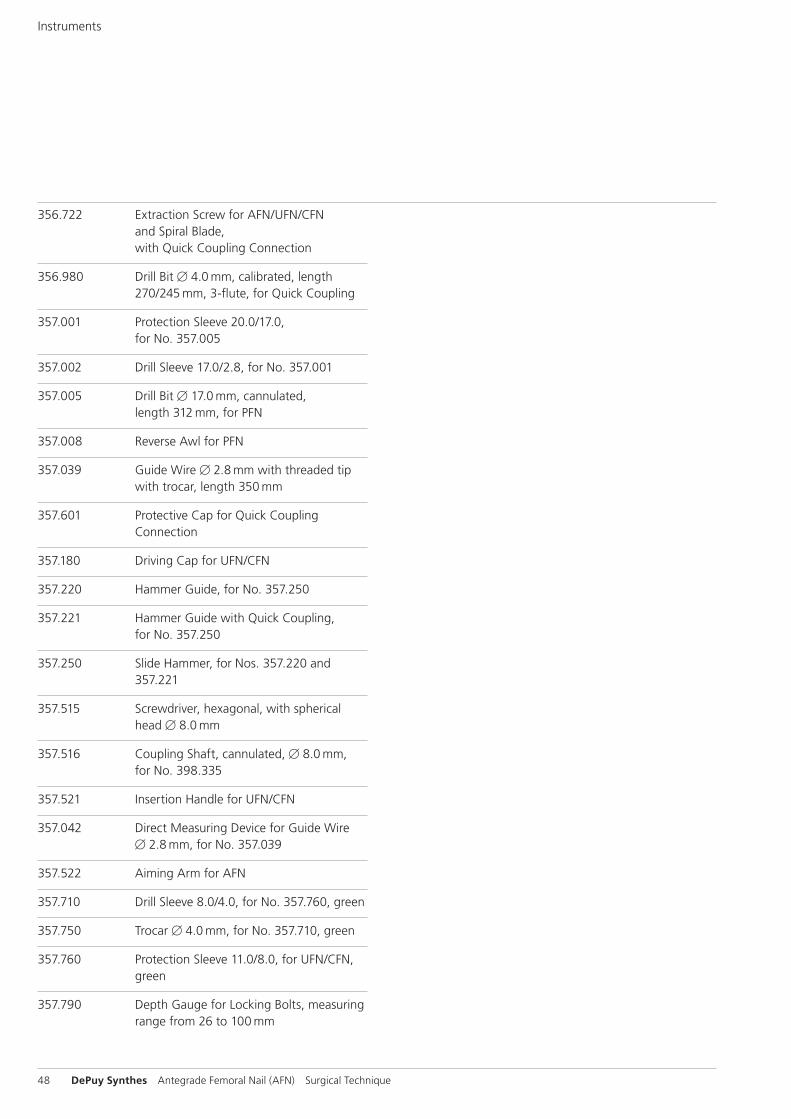
356.722 Extraction Screw for AFN/UFN/CFN and Spiral Blade, with Quick Coupling Connection
356.980 Drill Bit B 4.0 mm, calibrated, length 270/245 mm, 3-flute, for Quick Coupling
357.001 Protection Sleeve 20.0/17.0, for No. 357.005
357.002 Drill Sleeve 17.0/2.8, for No. 357.001
357.005 Drill Bit B 17.0 mm, cannulated, length 312 mm, for PFN
357.008 Reverse Awl for PFN
357.039 Guide Wire B 2.8 mm with threaded tip with trocar, length 350 mm
357.601 Protective Cap for Quick Coupling Connection
357.180 Driving Cap for UFN/CFN
357.220 Hammer Guide, for No. 357.250
357.221 Hammer Guide with Quick Coupling, for No. 357.250
357.250 Slide Hammer, for Nos. 357.220 and 357.221
357.515 Screwdriver, hexagonal, with spherical head B 8.0 mm
357.516 Coupling Shaft, cannulated, B 8.0 mm, for No. 398.335
357.521 Insertion Handle for UFN/CFN
357.042 Direct Measuring Device for Guide Wire B 2.8 mm, for No. 357.039
357.522 Aiming Arm for AFN
357.710 Drill Sleeve 8.0/4.0, for No. 357.760, green
357.750 Trocar B 4.0 mm, for No. 357.710, green
357.760 Protection Sleeve 11.0/8.0, for UFN/CFN, green
357.790 Depth Gauge for Locking Bolts, measuring range from 26 to 100 mm
Instruments
Antegrade Femoral Nail (AFN) Surgical Technique DePuy Synthes 49
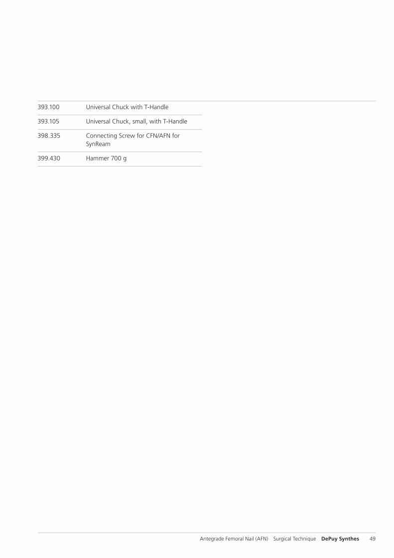
393.100 Universal Chuck with T-Handle
393.105 Universal Chuck, small, with T-Handle
398.335 Connecting Screw for CFN/AFN for SynReam
399.430 Hammer 700 g
50 DePuy Synthes Antegrade Femoral Nail (AFN) Surgical Technique
Literature
Rüedi T.P., Murphy W.M. (2000) AO Principles of Fracture Management. Stuttgart, New York: Thieme Publisher’s.
C. Krettek, P. Schandelmaier, and H. Tscherne. Stabilisierung von Femur schaftfrakturen mit dem Unaufgebohrten Femur Nagel (UFN) [Stabiliza tion of femoral shaft fractures using the Unreamed Femoral Nail (UFN)]. Part 1: Standardverriegelung [Standard locking]. Operat. Orthop. Traumatol. 10 (4): 183–197, 1998.
O P. A. Karpos, M. A. McFerran, and K.D. Johnson. Intra-medullary nailing of acute femoral shaft fractures using man-ual traction without a fracture table. J. Orthop. Trauma 9 (1): 57–62, 1995.
McFerran M.A., Johnson K.D. (1992) Intramedullary nailing of acute fe mo ral shaft fractures without a fracture table: techniques of using a fe mo ral distractor. J. Orthop Trauma 6: 271–278.
Antegrade Femoral Nail (AFN) Surgical Technique DePuy Synthes 51
MRI Information
Torque, Displacement and Image Artifacts according to ASTM F 2213-06, ASTM F 2052-06e1 and ASTM F 2119-07Non-clinical testing of worst case scenario in a 3 T MRI system did not reveal any relevant torque or displacement of the construct for an experimentally measured local spatial gradient of the magnetic field of 3.69 T/m. The largest image artifact extended approximately 169 mm from the construct when scanned using the Gradient Echo (GE). Testing was conducted on a 3 T MRI system.
Radio-Frequency-(RF-)induced heating according to ASTM F 2182-11aNon-clinical electromagnetic and thermal testing of worst case scenario lead to peak temperature rise of 9.5 °C with an average temperature rise of 6.6 °C (1.5 T) and a peak temperature rise of 5.9 °C (3 T) under MRI Conditions using RF Coils (whole body averaged specific absorption rate [SAR] of 2 W/kg for 6 minutes [1.5 T] and for 15 minutes [3 T]).
Precautions: The above mentioned test relies on non-clini - cal testing. The actual temperature rise in the patient will depend on a variety of factors beyond the SAR and time of RF application. Thus, it is recommended to pay particular attention to the following points: – It is recommended to thoroughly monitor patients under-
going MR scanning for perceived temperature and/or pain sensations.
– Patients with impaired thermoregulation or temperature sensation should be excluded from MR scanning proce - dures.
– Generally, it is recommended to use a MR system with low field strength in the presence of conductive implants. The employed specific absorption rate (SAR) should be reduced as far as possible.
– Using the ventilation system may further contribute to reduce temperature increase in the body.


Synthes GmbHEimattstrasse 34436 OberdorfSwitzerlandTel: +41 61 965 61 11Fax: +41 61 965 66 00www.depuysynthes.com 0123 ©
DeP
uy S
ynth
es T
raum
a, a
div
isio
n of
Syn
thes
Gm
bH. 2
016.
A
ll rig
hts
rese
rved
. 03
6.00
0.71
2 D
SEM
/TR
M/0
714/
0124
(2)
09/1
6
Not all products are currently available in all markets.
This publication is not intended for distribution in the USA.
All surgical techniques are available as PDF files at www.depuysynthes.com/ifu