Embed Size (px)
Citation preview
722 P. JANKOWSKI-MIHU OWICZ, D. KAWALEC, M. W GLARSKI, ANTENNA DESIGN FOR SEMI-PASSIVE UHF RFID …
DOI: 10.13164/re.2015.0722 APPLICATION OF WIRELESS COMMUNICATIONS
Antenna Design for Semi-Passive UHF RFID Transponder with Energy Harvester
Piotr JANKOWSKI-MIHU OWICZ, Damian KAWALEC, Mariusz W GLARSKI
Dept. of Electronic and Communications Systems, Rzeszów University of Technology, Pola 2, 35-959 Rzeszów, Poland
[email protected], [email protected], [email protected]
Abstract. A novel microstrip antenna which is dedicated to UHF semi-passive RFID transponders with an energy harvester is presented in this paper. The antenna structure designed and simulated by using Mentor Graphics Hyper-Lynx 3D EM software is described in details. The modeling and simulation results along with comparison with experi-mental data are analyzed and concluded. The main goal of the project is the need to eliminate a traditional battery form the transponder structure. The energy harvesting block, which is used instead, converts ambient energy (electromagnetic energy of typical radio communication system) into electrical power for internal circuitry. The additional function (gathering extra energy) of the trans-ponder antenna causes the necessity to create new designs in this scope.
Keywords Antenna design, semi-passive chip, RFID technique, microstrip antenna, energy harvesting
1. Introduction The radio frequency identification (RFID) technique
is often used in automated identification processes even at the present stage of its development [1]. It is implemented in complex hardware and software systems which have numerous applications in industry, commerce, science, medicine and many other fields [2–6].
In terms of hardware, an RFID system consists of a read/write device (RWD), its antenna and at least one transponder that is intended for marking an object. Com-munication in this system is provided with one or with multiple transponders simultaneously (single/anti-collision system). The marked objects during identification process may be placed in fixed point (static system) or may dy-namically change their location (dynamic system) [7]. The interrogation zone (IZ) is the main parameter of the RFID system – it determines the efficiency of a given automated process [1], [7]. The size of the interrogation zone strongly depends on the above mentioned arrangements of RWD and transponders. It should be emphasized that there is no
universal transponder at the commercial market that can be used for identifying any object in any automated process. In addition, the details about constructional parameters of transponders (of their antennas and used chips) are usually not specified in producers’ datasheets. It does not allow designers to estimate precisely IZ and the trial and error method has to be used during implementing an RFID system.
The process of transponder designing always starts with elaborating the antenna that should be matched to the chip to be selected. The application requirements, specific characteristics of target objects, frequency bands etc. should be taken into account. In the literature, it is easy to find antenna designs for classic UHF passive transponders [8–12]. However, the progress in electronics enables to crate new solutions in RFID chips (as internal harvester for additional energy, for example). It is the reason why the precise design guidelines have to be elaborated and new antennas have to be designed.
The modern design of semi-passive UHF transponder with an energy harvester is characterized in Sec. 2. The process of antenna synthesis for rare but commercially available type of chips is discussed in Sec. 3. The particu-lar attention was paid to the method of matching antenna and chip impedances (Sec. 3.1) and antenna construction (Sec. 3.2). The model of antenna was carried out in the Mentor Graphics HyperLynx 3D EM (HL3DEM) software tool and the adequate assumptions are described in Sec. 3.3. The practical implementation was made in PCB technology (Sec. 3.4). The work is summarized by the comparison of calculations and measurements (Sec. 3.5).
2. Semi-Passive UHF Transponder Radiative coupled RFID systems in the UHF band –
depending on the region of the world – typically operate in the range from 860 MHz to 960 MHz. Appropriate com-munication mechanisms are defined by the ISO/IEC 18000-6 protocol (EPC Class 1 Gen 2 [13]).
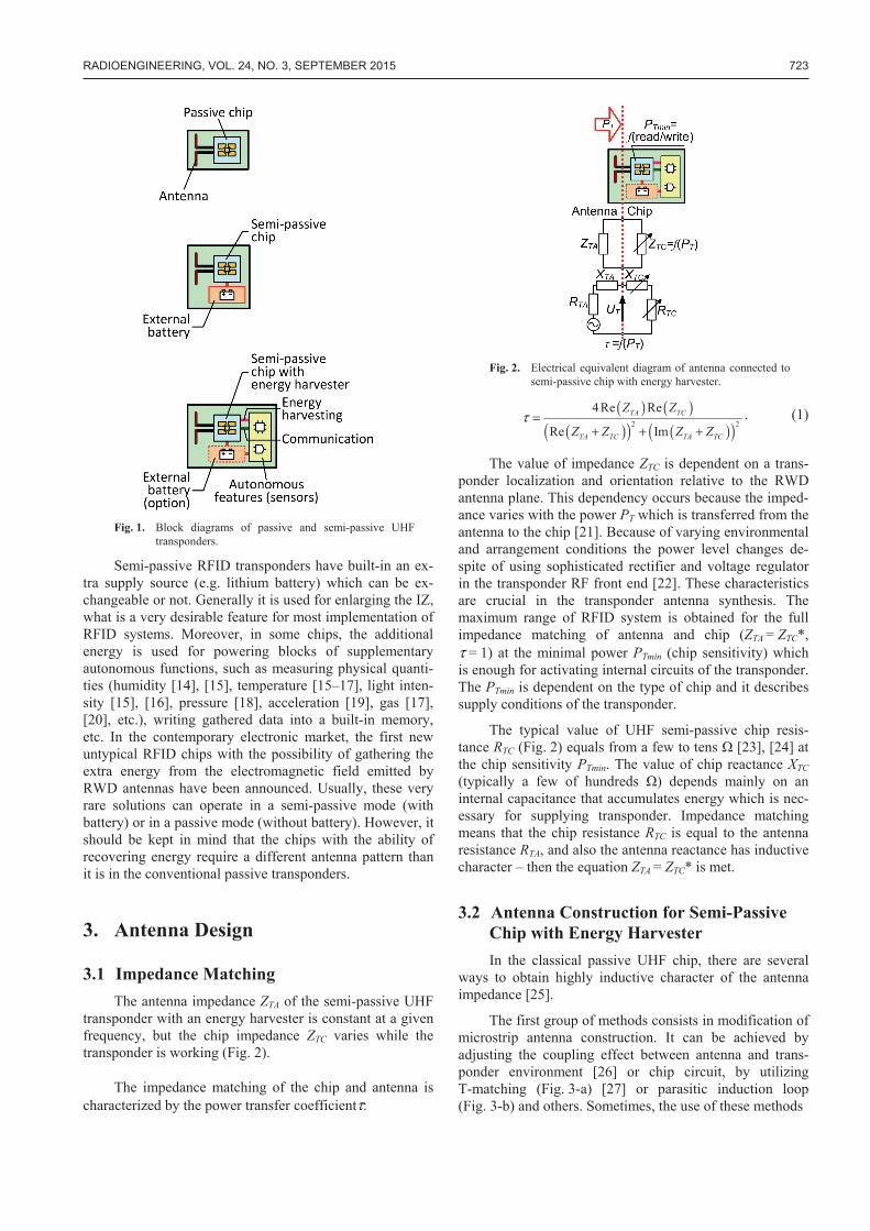
The most popular passive RFID transponder contains only the chip with the connected antenna (Fig. 1). Access to the internal memory of the chip can be done only by using the radio interface.
RADIOENGINEERING, VOL. 24, NO. 3, SEPTEMBER 2015 723
Fig. 1. Block diagrams of passive and semi-passive UHF
transponders.
Semi-passive RFID transponders have built-in an ex-tra supply source (e.g. lithium battery) which can be ex-changeable or not. Generally it is used for enlarging the IZ, what is a very desirable feature for most implementation of RFID systems. Moreover, in some chips, the additional energy is used for powering blocks of supplementary autonomous functions, such as measuring physical quanti-ties (humidity [14], [15], temperature [15–17], light inten-sity [15], [16], pressure [18], acceleration [19], gas [17], [20], etc.), writing gathered data into a built-in memory, etc. In the contemporary electronic market, the first new untypical RFID chips with the possibility of gathering the extra energy from the electromagnetic field emitted by RWD antennas have been announced. Usually, these very rare solutions can operate in a semi-passive mode (with battery) or in a passive mode (without battery). However, it should be kept in mind that the chips with the ability of recovering energy require a different antenna pattern than it is in the conventional passive transponders.
3. Antenna Design
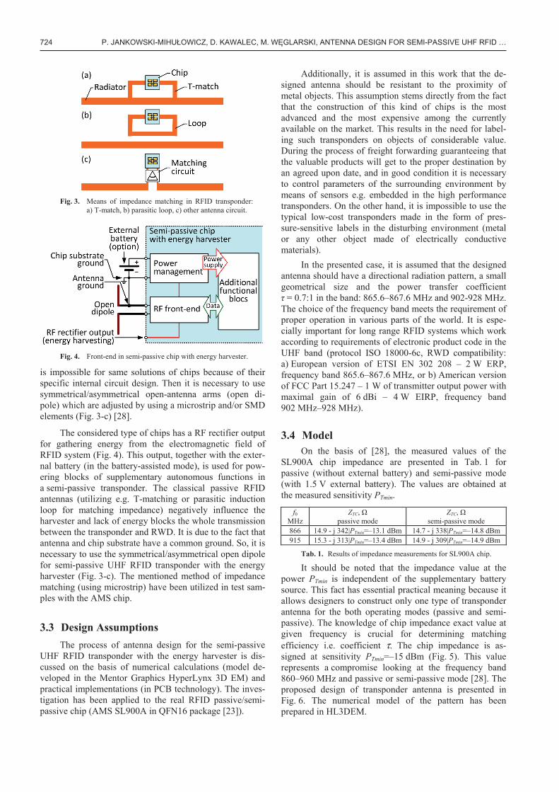
3.1 Impedance Matching The antenna impedance ZTA of the semi-passive UHF
transponder with an energy harvester is constant at a given frequency, but the chip impedance ZTC varies while the transponder is working (Fig. 2).
The impedance matching of the chip and antenna is characterized by the power transfer coefficientτ:
Fig. 2. Electrical equivalent diagram of antenna connected to
semi-passive chip with energy harvester.
( ) ( )( )( ) ( )( )2 2
4 Re Re
Re ImTA TC
TA TC TA TC
Z Z
Z Z Z Zτ =
+ + +. (1)
The value of impedance ZTC is dependent on a trans-ponder localization and orientation relative to the RWD antenna plane. This dependency occurs because the imped-ance varies with the power PT which is transferred from the antenna to the chip [21]. Because of varying environmental and arrangement conditions the power level changes de-spite of using sophisticated rectifier and voltage regulator in the transponder RF front end [22]. These characteristics are crucial in the transponder antenna synthesis. The maximum range of RFID system is obtained for the full impedance matching of antenna and chip (ZTA = ZTC*, τ = 1) at the minimal power PTmin (chip sensitivity) which is enough for activating internal circuits of the transponder. The PTmin is dependent on the type of chip and it describes supply conditions of the transponder.
The typical value of UHF semi-passive chip resis-tance RTC (Fig. 2) equals from a few to tens [23], [24] at the chip sensitivity PTmin. The value of chip reactance XTC (typically a few of hundreds ) depends mainly on an internal capacitance that accumulates energy which is nec-essary for supplying transponder. Impedance matching means that the chip resistance RTC is equal to the antenna resistance RTA, and also the antenna reactance has inductive character – then the equation ZTA = ZTC* is met.
3.2 Antenna Construction for Semi-Passive Chip with Energy Harvester In the classical passive UHF chip, there are several
ways to obtain highly inductive character of the antenna impedance [25].
The first group of methods consists in modification of microstrip antenna construction. It can be achieved by adjusting the coupling effect between antenna and trans-ponder environment [26] or chip circuit, by utilizing T-matching (Fig. 3-a) [27] or parasitic induction loop (Fig. 3-b) and others. Sometimes, the use of these methods
724 P. JANKOWSKI-MIHU OWICZ, D. KAWALEC, M. W GLARSKI, ANTENNA DESIGN FOR SEMI-PASSIVE UHF RFID …
Fig. 3. Means of impedance matching in RFID transponder:
a) T-match, b) parasitic loop, c) other antenna circuit.
Fig. 4. Front-end in semi-passive chip with energy harvester.
is impossible for same solutions of chips because of their specific internal circuit design. Then it is necessary to use symmetrical/asymmetrical open-antenna arms (open di-pole) which are adjusted by using a microstrip and/or SMD elements (Fig. 3-c) [28].
The considered type of chips has a RF rectifier output for gathering energy from the electromagnetic field of RFID system (Fig. 4). This output, together with the exter-nal battery (in the battery-assisted mode), is used for pow-ering blocks of supplementary autonomous functions in a semi-passive transponder. The classical passive RFID antennas (utilizing e.g. T-matching or parasitic induction loop for matching impedance) negatively influence the harvester and lack of energy blocks the whole transmission between the transponder and RWD. It is due to the fact that antenna and chip substrate have a common ground. So, it is necessary to use the symmetrical/asymmetrical open dipole for semi-passive UHF RFID transponder with the energy harvester (Fig. 3-c). The mentioned method of impedance matching (using microstrip) have been utilized in test sam-ples with the AMS chip.
3.3 Design Assumptions The process of antenna design for the semi-passive
UHF RFID transponder with the energy harvester is dis-cussed on the basis of numerical calculations (model de-veloped in the Mentor Graphics HyperLynx 3D EM) and practical implementations (in PCB technology). The inves-tigation has been applied to the real RFID passive/semi-passive chip (AMS SL900A in QFN16 package [23]).
Additionally, it is assumed in this work that the de-signed antenna should be resistant to the proximity of metal objects. This assumption stems directly from the fact that the construction of this kind of chips is the most advanced and the most expensive among the currently available on the market. This results in the need for label-ing such transponders on objects of considerable value. During the process of freight forwarding guaranteeing that the valuable products will get to the proper destination by an agreed upon date, and in good condition it is necessary to control parameters of the surrounding environment by means of sensors e.g. embedded in the high performance transponders. On the other hand, it is impossible to use the typical low-cost transponders made in the form of pres-sure-sensitive labels in the disturbing environment (metal or any other object made of electrically conductive materials).
In the presented case, it is assumed that the designed antenna should have a directional radiation pattern, a small geometrical size and the power transfer coefficient = 0.7:1 in the band: 865.6–867.6 MHz and 902-928 MHz.
The choice of the frequency band meets the requirement of proper operation in various parts of the world. It is espe-cially important for long range RFID systems which work according to requirements of electronic product code in the UHF band (protocol ISO 18000-6c, RWD compatibility: a) European version of ETSI EN 302 208 – 2 W ERP, frequency band 865.6–867.6 MHz, or b) American version of FCC Part 15.247 – 1 W of transmitter output power with maximal gain of 6 dBi – 4 W EIRP, frequency band 902 MHz–928 MHz).
3.4 Model On the basis of [28], the measured values of the
SL900A chip impedance are presented in Tab. 1 for passive (without external battery) and semi-passive mode (with 1.5 V external battery). The values are obtained at the measured sensitivity PTmin.
f0 MHz
ZTC, passive mode
ZTC, semi-passive mode
866 14.9 - j 342|PTmin=–13.1 dBm 14.7 - j 338|PTmin=–14.8 dBm 915 15.3 - j 313|PTmin=–13.4 dBm 14.9 - j 309|PTmin=–14.9 dBm
Tab. 1. Results of impedance measurements for SL900A chip.
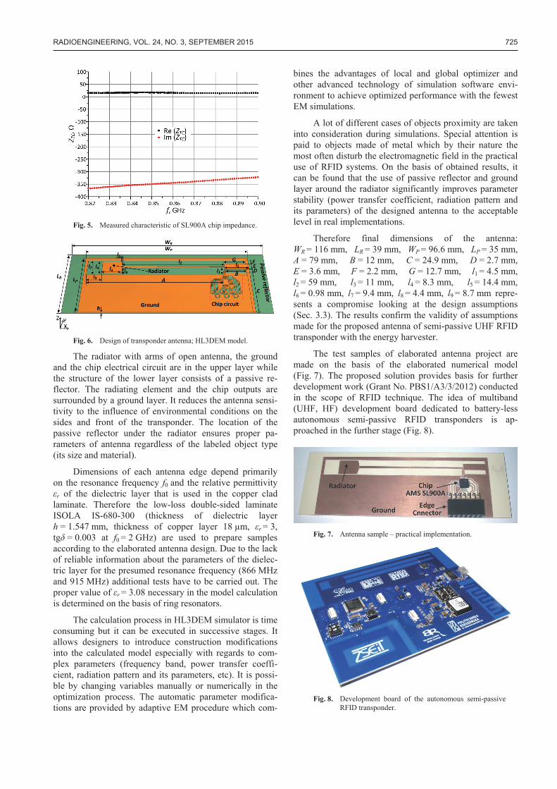
It should be noted that the impedance value at the power PTmin is independent of the supplementary battery source. This fact has essential practical meaning because it allows designers to construct only one type of transponder antenna for the both operating modes (passive and semi-passive). The knowledge of chip impedance exact value at given frequency is crucial for determining matching efficiency i.e. coefficient τ. The chip impedance is as-signed at sensitivity PTmin=–15 dBm (Fig. 5). This value represents a compromise looking at the frequency band 860–960 MHz and passive or semi-passive mode [28]. The proposed design of transponder antenna is presented in Fig. 6. The numerical model of the pattern has been prepared in HL3DEM.
RADIOENGINEERING, VOL. 24, NO. 3, SEPTEMBER 2015 725
Fig. 5. Measured characteristic of SL900A chip impedance.
Fig. 6. Design of transponder antenna; HL3DEM model.
The radiator with arms of open antenna, the ground and the chip electrical circuit are in the upper layer while the structure of the lower layer consists of a passive re-flector. The radiating element and the chip outputs are surrounded by a ground layer. It reduces the antenna sensi-tivity to the influence of environmental conditions on the sides and front of the transponder. The location of the passive reflector under the radiator ensures proper pa-rameters of antenna regardless of the labeled object type (its size and material).
Dimensions of each antenna edge depend primarily on the resonance frequency f0 and the relative permittivity
r of the dielectric layer that is used in the copper clad laminate. Therefore the low-loss double-sided laminate ISOLA IS-680-300 (thickness of dielectric layer h = 1.547 mm, thickness of copper layer 18 μm, r = 3, tg = 0.003 at f0 = 2 GHz) are used to prepare samples according to the elaborated antenna design. Due to the lack of reliable information about the parameters of the dielec-tric layer for the presumed resonance frequency (866 MHz and 915 MHz) additional tests have to be carried out. The proper value of r = 3.08 necessary in the model calculation is determined on the basis of ring resonators.
The calculation process in HL3DEM simulator is time consuming but it can be executed in successive stages. It allows designers to introduce construction modifications into the calculated model especially with regards to com-plex parameters (frequency band, power transfer coeffi-cient, radiation pattern and its parameters, etc). It is possi-ble by changing variables manually or numerically in the optimization process. The automatic parameter modifica-tions are provided by adaptive EM procedure which com-
bines the advantages of local and global optimizer and other advanced technology of simulation software envi-ronment to achieve optimized performance with the fewest EM simulations.
A lot of different cases of objects proximity are taken into consideration during simulations. Special attention is paid to objects made of metal which by their nature the most often disturb the electromagnetic field in the practical use of RFID systems. On the basis of obtained results, it can be found that the use of passive reflector and ground layer around the radiator significantly improves parameter stability (power transfer coefficient, radiation pattern and its parameters) of the designed antenna to the acceptable level in real implementations.
Therefore final dimensions of the antenna: WR = 116 mm, LR = 39 mm, WP = 96.6 mm, LP = 35 mm, A = 79 mm, B = 12 mm, C = 24.9 mm, D = 2.7 mm, E = 3.6 mm, F = 2.2 mm, G = 12.7 mm, l1 = 4.5 mm, l2 = 59 mm, l3 = 11 mm, l4 = 8.3 mm, l5 = 14.4 mm, l6 = 0.98 mm, l7 = 9.4 mm, l8 = 4.4 mm, l9 = 8.7 mm repre-sents a compromise looking at the design assumptions (Sec. 3.3). The results confirm the validity of assumptions made for the proposed antenna of semi-passive UHF RFID transponder with the energy harvester.
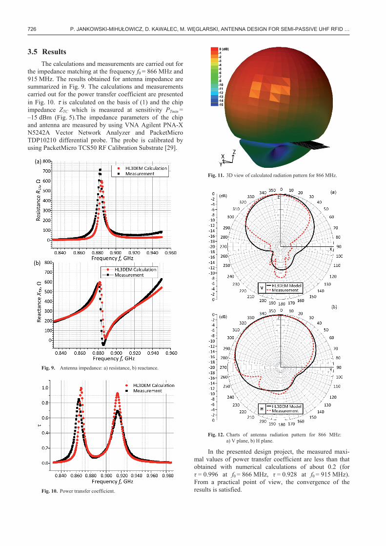
The test samples of elaborated antenna project are made on the basis of the elaborated numerical model (Fig. 7). The proposed solution provides basis for further development work (Grant No. PBS1/A3/3/2012) conducted in the scope of RFID technique. The idea of multiband (UHF, HF) development board dedicated to battery-less autonomous semi-passive RFID transponders is ap-proached in the further stage (Fig. 8).
Fig. 7. Antenna sample – practical implementation.
Fig. 8. Development board of the autonomous semi-passive
RFID transponder.
726 P. JANKOWSKI-MIHU OWICZ, D. KAWALEC, M. W GLARSKI, ANTENNA DESIGN FOR SEMI-PASSIVE UHF RFID …
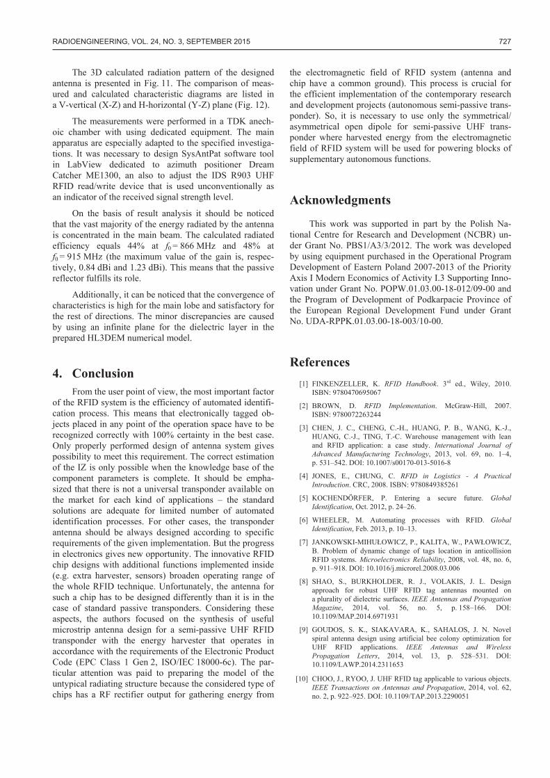
3.5 Results The calculations and measurements are carried out for
the impedance matching at the frequency f0 = 866 MHz and 915 MHz. The results obtained for antenna impedance are summarized in Fig. 9. The calculations and measurements carried out for the power transfer coefficient are presented in Fig. 10. τ is calculated on the basis of (1) and the chip impedance ZTC which is measured at sensitivity PTmin = –15 dBm (Fig. 5).The impedance parameters of the chip and antenna are measured by using VNA Agilent PNA-X N5242A Vector Network Analyzer and PacketMicro TDP10210 differential probe. The probe is calibrated by using PacketMicro TCS50 RF Calibration Substrate [29].
Fig. 9. Antenna impedance: a) resistance, b) reactance.
Fig. 10. Power transfer coefficient.
Fig. 11. 3D view of calculated radiation pattern for 866 MHz.
Fig. 12. Charts of antenna radiation pattern for 866 MHz:
a) V plane, b) H plane.
In the presented design project, the measured maxi-mal values of power transfer coefficient are less than that obtained with numerical calculations of about 0.2 (for = 0.996 at f0 = 866 MHz, = 0.928 at f0 = 915 MHz).
From a practical point of view, the convergence of the results is satisfied.
RADIOENGINEERING, VOL. 24, NO. 3, SEPTEMBER 2015 727
The 3D calculated radiation pattern of the designed antenna is presented in Fig. 11. The comparison of meas-ured and calculated characteristic diagrams are listed in a V-vertical (X-Z) and H-horizontal (Y-Z) plane (Fig. 12).
The measurements were performed in a TDK anech-oic chamber with using dedicated equipment. The main apparatus are especially adapted to the specified investiga-tions. It was necessary to design SysAntPat software tool in LabView dedicated to azimuth positioner Dream Catcher ME1300, an also to adjust the IDS R903 UHF RFID read/write device that is used unconventionally as an indicator of the received signal strength level.
On the basis of result analysis it should be noticed that the vast majority of the energy radiated by the antenna is concentrated in the main beam. The calculated radiated efficiency equals 44% at f0 = 866 MHz and 48% at f0 = 915 MHz (the maximum value of the gain is, respec-tively, 0.84 dBi and 1.23 dBi). This means that the passive reflector fulfills its role.
Additionally, it can be noticed that the convergence of characteristics is high for the main lobe and satisfactory for the rest of directions. The minor discrepancies are caused by using an infinite plane for the dielectric layer in the prepared HL3DEM numerical model.
4. Conclusion From the user point of view, the most important factor
of the RFID system is the efficiency of automated identifi-cation process. This means that electronically tagged ob-jects placed in any point of the operation space have to be recognized correctly with 100% certainty in the best case. Only properly performed design of antenna system gives possibility to meet this requirement. The correct estimation of the IZ is only possible when the knowledge base of the component parameters is complete. It should be empha-sized that there is not a universal transponder available on the market for each kind of applications – the standard solutions are adequate for limited number of automated identification processes. For other cases, the transponder antenna should be always designed according to specific requirements of the given implementation. But the progress in electronics gives new opportunity. The innovative RFID chip designs with additional functions implemented inside (e.g. extra harvester, sensors) broaden operating range of the whole RFID technique. Unfortunately, the antenna for such a chip has to be designed differently than it is in the case of standard passive transponders. Considering these aspects, the authors focused on the synthesis of useful microstrip antenna design for a semi-passive UHF RFID transponder with the energy harvester that operates in accordance with the requirements of the Electronic Product Code (EPC Class 1 Gen 2, ISO/IEC 18000-6c). The par-ticular attention was paid to preparing the model of the untypical radiating structure because the considered type of chips has a RF rectifier output for gathering energy from
the electromagnetic field of RFID system (antenna and chip have a common ground). This process is crucial for the efficient implementation of the contemporary research and development projects (autonomous semi-passive trans-ponder). So, it is necessary to use only the symmetrical/ asymmetrical open dipole for semi-passive UHF trans-ponder where harvested energy from the electromagnetic field of RFID system will be used for powering blocks of supplementary autonomous functions.
Acknowledgments
This work was supported in part by the Polish Na-tional Centre for Research and Development (NCBR) un-der Grant No. PBS1/A3/3/2012. The work was developed by using equipment purchased in the Operational Program Development of Eastern Poland 2007-2013 of the Priority Axis I Modern Economics of Activity I.3 Supporting Inno-vation under Grant No. POPW.01.03.00-18-012/09-00 and the Program of Development of Podkarpacie Province of the European Regional Development Fund under Grant No. UDA-RPPK.01.03.00-18-003/10-00.
References [1] FINKENZELLER, K. RFID Handbook. 3rd ed., Wiley, 2010.
ISBN: 9780470695067
[2] BROWN, D. RFID Implementation. McGraw-Hill, 2007. ISBN: 9780072263244
[3] CHEN, J. C., CHENG, C.-H., HUANG, P. B., WANG, K.-J., HUANG, C.-J., TING, T.-C. Warehouse management with lean and RFID application: a case study. International Journal of Advanced Manufacturing Technology, 2013, vol. 69, no. 1–4, p. 531–542. DOI: 10.1007/s00170-013-5016-8
[4] JONES, E., CHUNG, C. RFID in Logistics - A Practical Introduction. CRC, 2008. ISBN: 9780849385261
[5] KOCHENDÖRFER, P. Entering a secure future. Global Identification, Oct. 2012, p. 24–26.
[6] WHEELER, M. Automating processes with RFID. Global Identification, Feb. 2013, p. 10–13.
[7] JANKOWSKI-MIHU OWICZ, P., KALITA, W., PAW OWICZ, B. Problem of dynamic change of tags location in anticollision RFID systems. Microelectronics Reliability, 2008, vol. 48, no. 6, p. 911–918. DOI: 10.1016/j.microrel.2008.03.006
[8] SHAO, S., BURKHOLDER, R. J., VOLAKIS, J. L. Design approach for robust UHF RFID tag antennas mounted on a plurality of dielectric surfaces. IEEE Antennas and Propagation Magazine, 2014, vol. 56, no. 5, p. 158–166. DOI: 10.1109/MAP.2014.6971931
[9] GOUDOS, S. K., SIAKAVARA, K., SAHALOS, J. N. Novel spiral antenna design using artificial bee colony optimization for UHF RFID applications. IEEE Antennas and Wireless Propagation Letters, 2014, vol. 13, p. 528–531. DOI: 10.1109/LAWP.2014.2311653
[10] CHOO, J., RYOO, J. UHF RFID tag applicable to various objects. IEEE Transactions on Antennas and Propagation, 2014, vol. 62, no. 2, p. 922–925. DOI: 10.1109/TAP.2013.2290051

728 P. JANKOWSKI-MIHU OWICZ, D. KAWALEC, M. W GLARSKI, ANTENNA DESIGN FOR SEMI-PASSIVE UHF RFID …
[11] SUN, X.-B., XIE, J., CAO, M.-Y. RFID tag antenna design based on an improved coupling source shape. IEEE Antennas and Wireless Propagation Letters, 2013, vol. 12, p. 532–534. DOI: 10.1109/LAWP.2013.2255856
[12] ZAMORA, G., ZUFFANELLI, S., PAREDES, F., MARIN, F., BONACHE, J. Design and synthesis methodology for UHF-RFID tags based on the T-match network. IEEE Transactions on Microwave Theory and Techniques, 2013, vol. 61, no. 12, p. 4090–4098. DOI: 10.1109/TMTT.2013.2287856
[13] GS1 EPCglobal. EPC Radio-Frequency Identity Protocols Generation-2 UHF RFID; Specification for RFID Air Interface Protocol for Communications at 860 MHz – 960 MHz. Ver. 2.0.0, Nov-2013. [Online] Available at: http://www.gs1.org/epcglobal
[14] PHAN, N. D., CHANG, I. J., LEE, J. W. A 2-Kb one-time programmable memory for UHF passive RFID tag IC in a standard 0.18 m CMOS process. IEEE Transactions on Circuits and Systems I, 2012, vol. 60, no. 7, p. 1810–1822. DOI: 10.1109/TCSI.2012.2230500
[15] SLOSAR ÍK, S., VEHEC, I., KALITA, W., BAUER, R., SABAT, W. 3D shaped module with integrated pressure sensor ATP Jour-nal plus, 2007, vol. 1, p. 228–230. ISSN: 1336-5010 (in Slovak).
[16] LEE, C. W., LEE, S. J., KIM, M., KYUNG, Y., EOM, K. Capacitive humidity sensor tag smart refrigerator system using the capacitive to voltage converter (CVC). International Journal of Science and Advanced Technology, 2011, vol. 36, p. 15–26. ISSN: 2221-8386
[17] ABAD, E., MAZZOLAI, B., JUARROS, A., GÓMEZ, D., MONDINI, A., SAYHAN, I., KRENKOW, A., BECKER, T. Fabrication process for a flexible tag microlab. Proceedings of SPIE, vol. 6589, Smart Sensors, Actuators, 2007, 65890O. DOI: 10.1117/12.723737
[18] OPREA, A., BÂRSAN, N., WEIMAR, U., BAUERSFELD, M. L., EBLING, D., WÖLLENSTEIN, J. Capacitive humidity sensors on flexible RFID labels. Sensors and Actuators B, 2008, vol. 132, no. 2, p. 404–410. DOI: 10.1016/j.snb.2007.10.010
[19] VOLK, T., JANSEN, D., SPELETZ, H., FLEINER, B., BAU, D., KREKER, A., RISKE, A. Active RFID sensor with integrated file system for logistic applications. In Proceedings of 2010 European Workshop on Smart Objects: Systems, Technologies and Applica-tions. Ciudad (Spain), 2010, p. 1–7. ISBN: 9783800732821
[20] KIM, S., CHO, J. H., KIM, H. S., KIM, H., KANG, H. B., HONG, S. K. An EPC Gen 2 compatible passive/semi-active UHF RFID transponder with embedded FeRAM and temperature sensor. In Proc. of IEEE Asian Solid-State Circuits Conference. Jeju (South Korea), 2007. p. 135–138. DOI: 10.1109/ASSCC.2007.4425750
[21] DE VITA, G., IANNACCONE, G. Design criteria for the RF section of UHF and microwave passive RFID transponders. IEEE Transactions on Microwave Theory and Techniques, 2005, vol. 53, no. 9, p. 2978–2990. DOI: 10.1109/TMTT.2005.854229
[22] WEI, P., CHE, W., BI, Z., WEI, C., NA, Y., QIANG, L., HAO, M. High-efficiency differential RF front-end for a Gen2 RFID tag. IEEE Transactions on Circuits and Systems II, 2011, vol. 58, no. 4, p. 189–194. DOI: 10.1109/TCSII.2011.2124530
[23] AMS. SL900A EPC Class 3 Sensory Tag Chip - For Automatic Data Logging. AMS Datasheet, 2014-May-06, v1-01.
[24] RAMTRON. WM72016 – 16Kbit Secure F-RAM Memory with Gen-2 RFID Access & Serial Port Direct Memory Access. Product Specification, Rev. 3.0, Sep. 2012.
[25] MARROCCO, G. The art of UHF RFID antenna design: imped-ance-matching and size-reduction techniques. IEEE Antennas and Propagation Magazine, 2008 vol. 50, no. 1, p. 66–79. DOI: 10.1109/MAP.2008.4494504
[26] KIM, D, YEO, J. Dual-band long-range passive RFID tag antenna using an AMC ground plane. IEEE Transactions on Antennas and
Propagation, 2012, vol. 60, no. 6, p. 2620–2626. DOI: 10.1109/TAP.2012.2194638
[27] MOHAMMED, N. A., DEMAREST, K., DEAVOURS, D. D. Analysis and synthesis of UHF RFID antennas using the embedded T-match. In Proceedings of the IEEE International Conference on RFID. Orlando, (FL, USA), 2010, p. 230–236. DOI: 10.1109/RFID.2010.5467276
[28] JANKOWSKI-MIHU OWICZ, P., W GLARSKI, M. Determina-tion of passive and semi-passive chip parameters required for syn-thesis of interrogation zone in UHF RFID systems. Elektronika ir Elektrotechnika (Electronics and Electrical Engineering), 2014, vol. 20, no. 9, p. 65–73. DOI: 10.5755/j01.eee.20.9.5007
[29] JANKOWSKI-MIHU OWICZ, P., PITERA, G., W GLARSKI, M. The impedance measurement problem in antennas for RFID technique. Metrology and Measurement Systems, 2014, vol. XXI, no 3, p. 509–520. DOI: 10.2478/mms-2014-0043
About the Authors ... Piotr JANKOWSKI-MIHU OWICZ was born in 1974. He received the MSc. degree in the specialization of Elec-tronic Devices from the Faculty of Electrical Engineering, Rzeszów University of Technology (Poland), in 1999, and the Ph.D. degree in the field of Telecommunications at AGH University of Science and Technology, in 2007. Since 2007, he has been an Assistant Professor with the Dept. of Electronic and Communications Systems (ZSEiT), Faculty of Electrical and Computer Engineering, Rzeszów University of Technology. He is the author of numerous publications and studies for industry. His scientific re-search is focusing on antennas, RFID systems and their practical uses. He co-operates with companies in the coun-try and abroad in order to solve problems from the range of RFID technology. Dr. Jankowski-Mihu owicz is a Member of IEEE, IMAPS and SEP.
Damian KAWALEC received his BSc. and MSc. diploma in Electronics and Telecommunications from Rzeszów University of Technology in 2009 and 2011, respectively. Since 2013 he participates in research project “Synthesis of autonomous semi-passive transponder dedicated to opera-tion in anti-collision dynamic RFID systems”. His research interests include antenna designing, EM wave propagation and modeling of RFID systems. Currently he is a PhD student in the Dept. of Electronic and Communications Systems, Rzeszów University of Technology.
Mariusz W GLARSKI was born in 1971. In 1996 he graduated (MSc.) in the specialization of Electronic De-vices from the Faculty of Electrical Engineering, Rzeszów University of Technology, Poland. He defended his PhD thesis in the field of Electrical Engineering at the Faculty of Electrical and Computer Engineering, Rzeszów University of Technology, in 2005. Since 1996, he has been an Assistant Professor in the Dept. of Electronic and Communications Systems, Rzeszów University of Tech-nology. He is the author of more than 50 publications. His scientific research is focusing on hybrid microelectronic and microsystem technology, analysis of temperature fields, RFID systems technology and their applications. Dr. W glarski is a Member of IEEE, IMAPS and SEP.