Embed Size (px)
DESCRIPTION
ANTENAS
Citation preview
1 - 1
Ain Shams UniversityFaculty of Engineering
Electronics and Comm. Eng. Dept.
Antennas4th Year
2000/2001 2nd Semester
EXERCISE (1)
VECTOR ANALYSIS
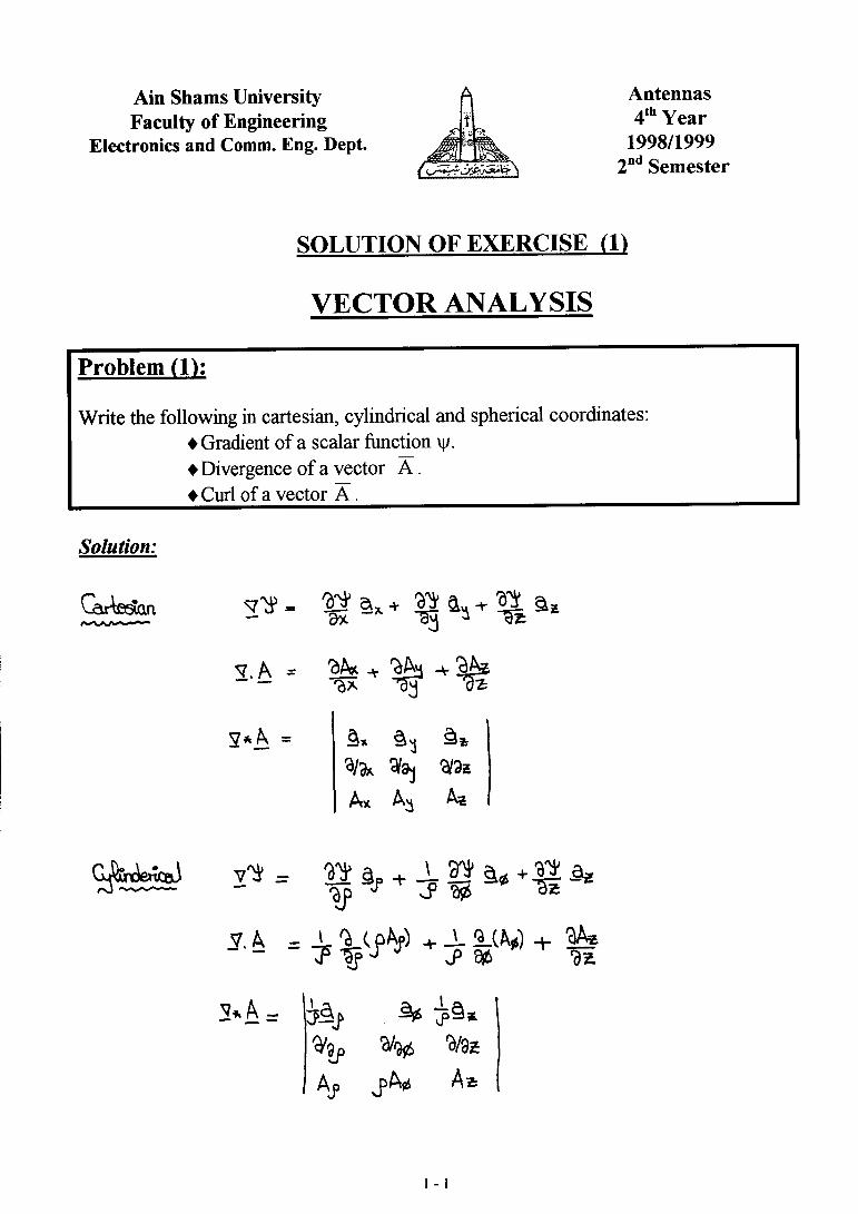
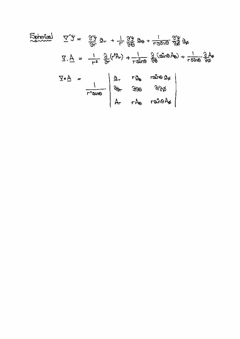
1 . Write the following in cartesian, cylindrical and spherical coordinates: ♦ Gradient of a scalar function ψ. ♦ Divergence of a vector A .
♦ Curl of a vector A .
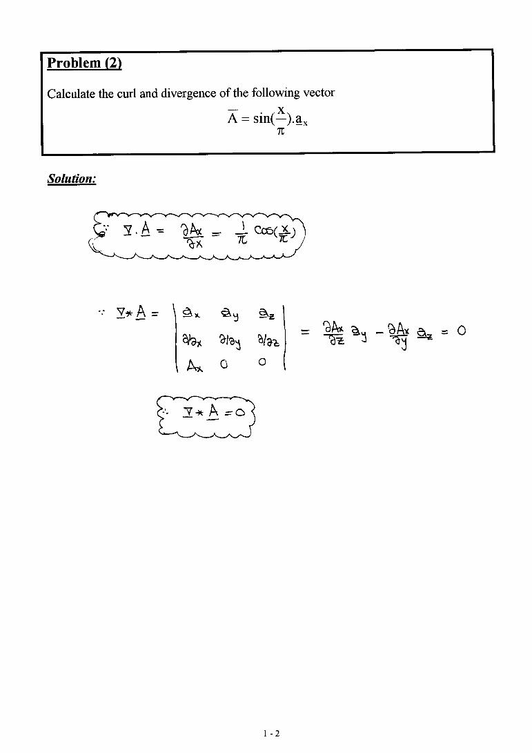
2 . Calculate the curl and divergence of the following vector
Ax
ax= sin( ).π
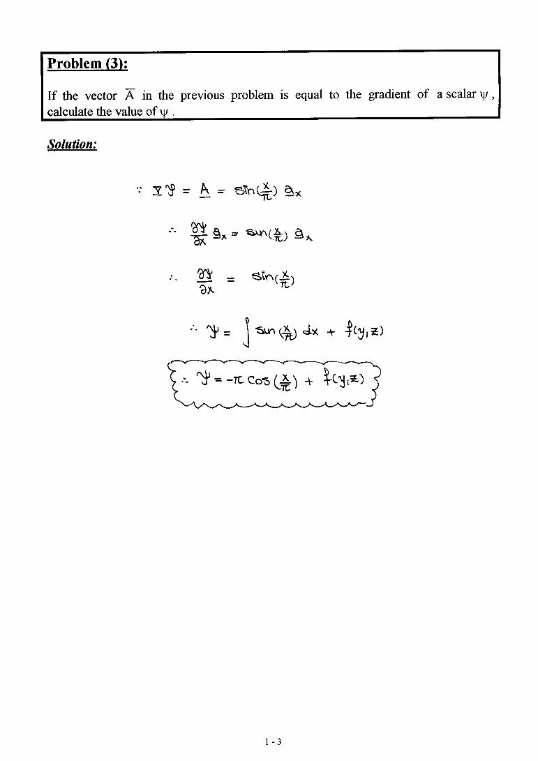
3 . If the vector A in the previous problem is equal to the gradient of a scalar ψ ,calculate the value of ψ .
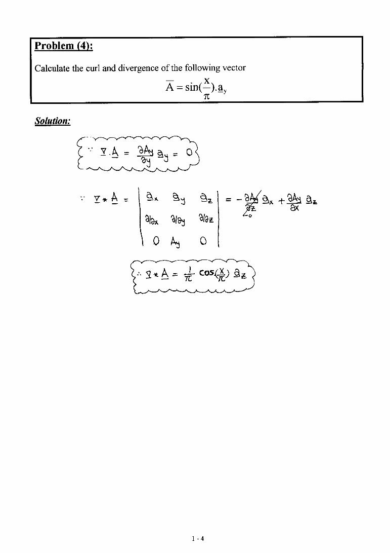
4 . Calculate the curl and divergence of the following vector
Ax
ay= sin( ).π
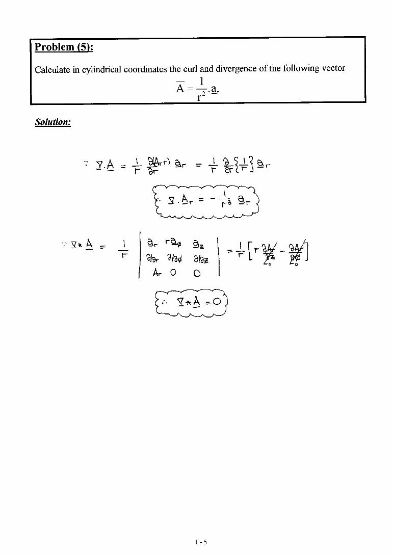
5 . Calculate in cylindrical coordinates the curl and divergence of the followingvector
Ar
a r=12
.
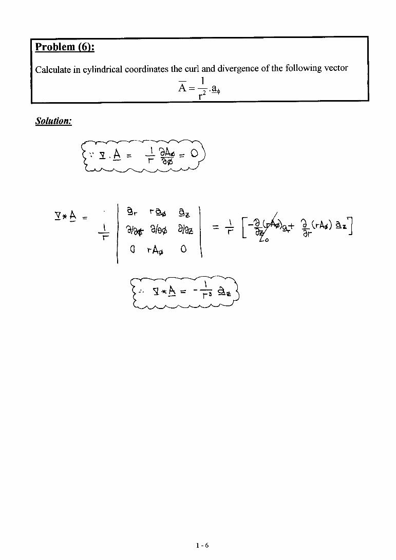
6 . Calculate in cylindrical coordinates the curl and divergence of the followingvector
Ar
a=12
. φ
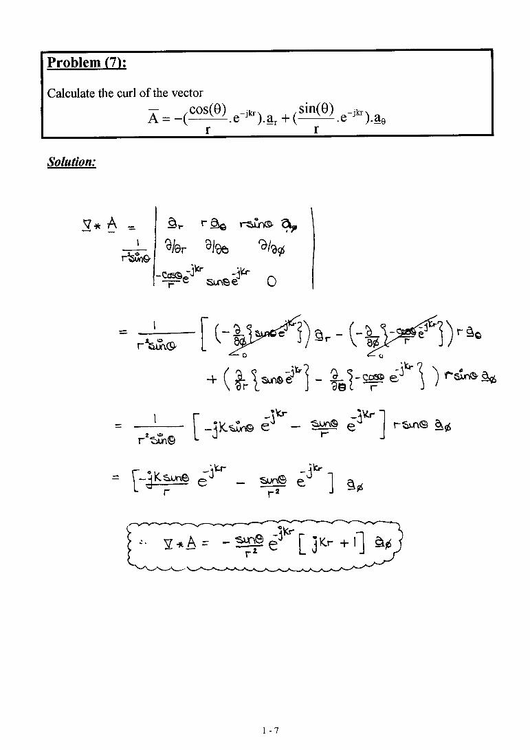
7 . Calculate the curl of the vector
Ar
e ar
e ajkrr
jkr= − +− −(cos( )
. ). (sin( )
. ).θ θ
θ
1 - 2
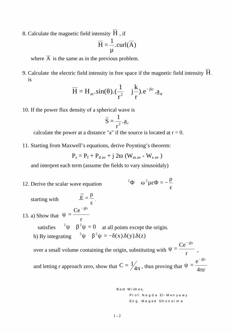
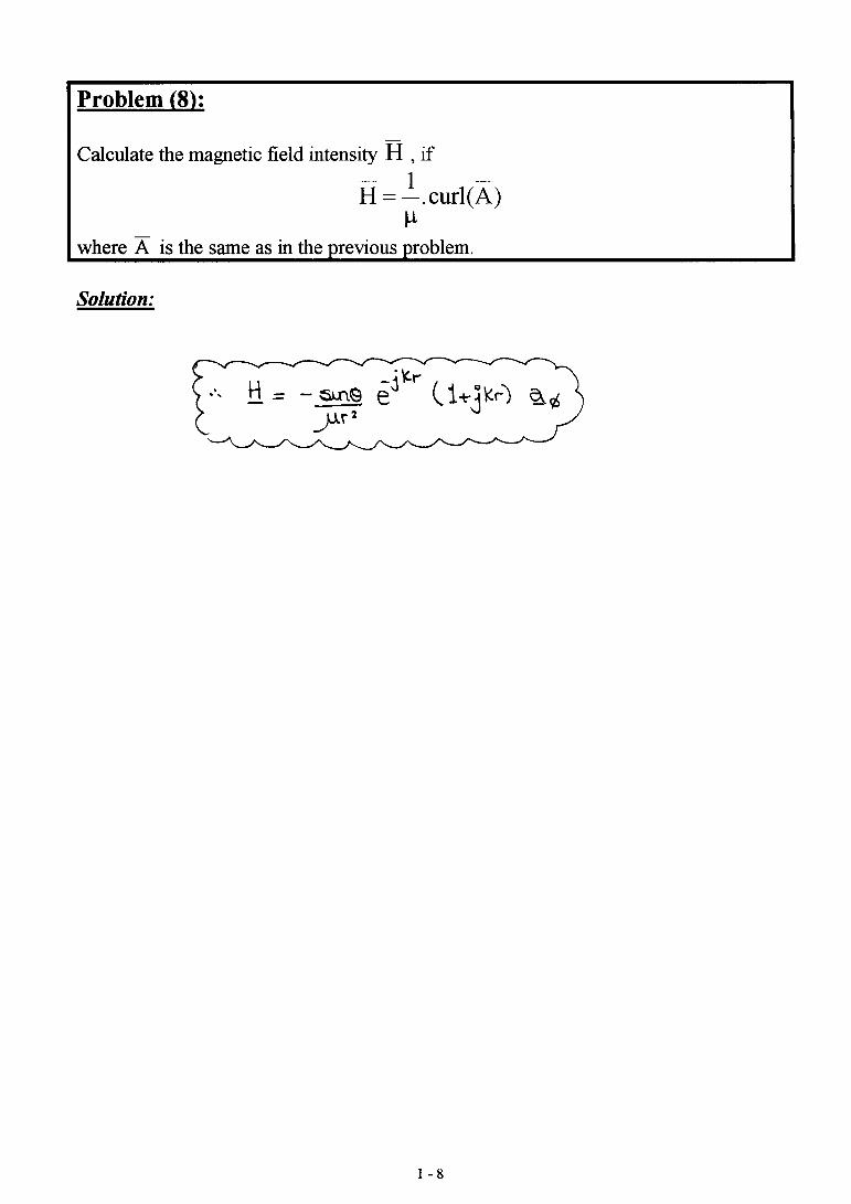
8 . Calculate the magnetic field intensity H , if
H curl A= 1µ
. ( )
where A is the same as in the previous problem.
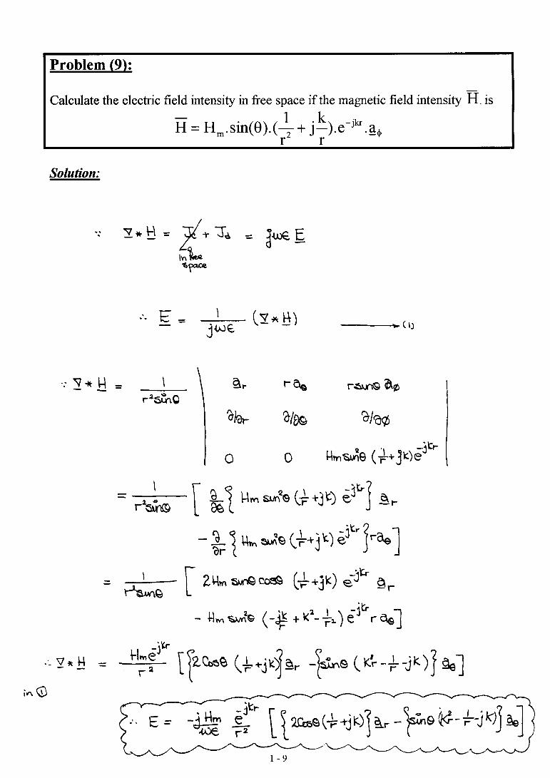
9 . Calculate the electric field intensity in free space if the magnetic field intensity H .
is
H Hr
jkr
e amjkr= + −.sin( ).( ). .θ φ
12
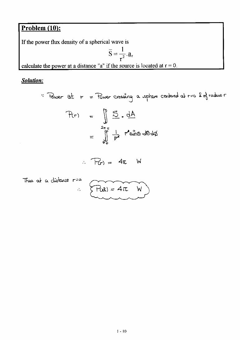
10 . If the power flux density of a spherical wave is
Sr
a r=12
.
calculate the power at a distance "a" if the source is located at r = 0.
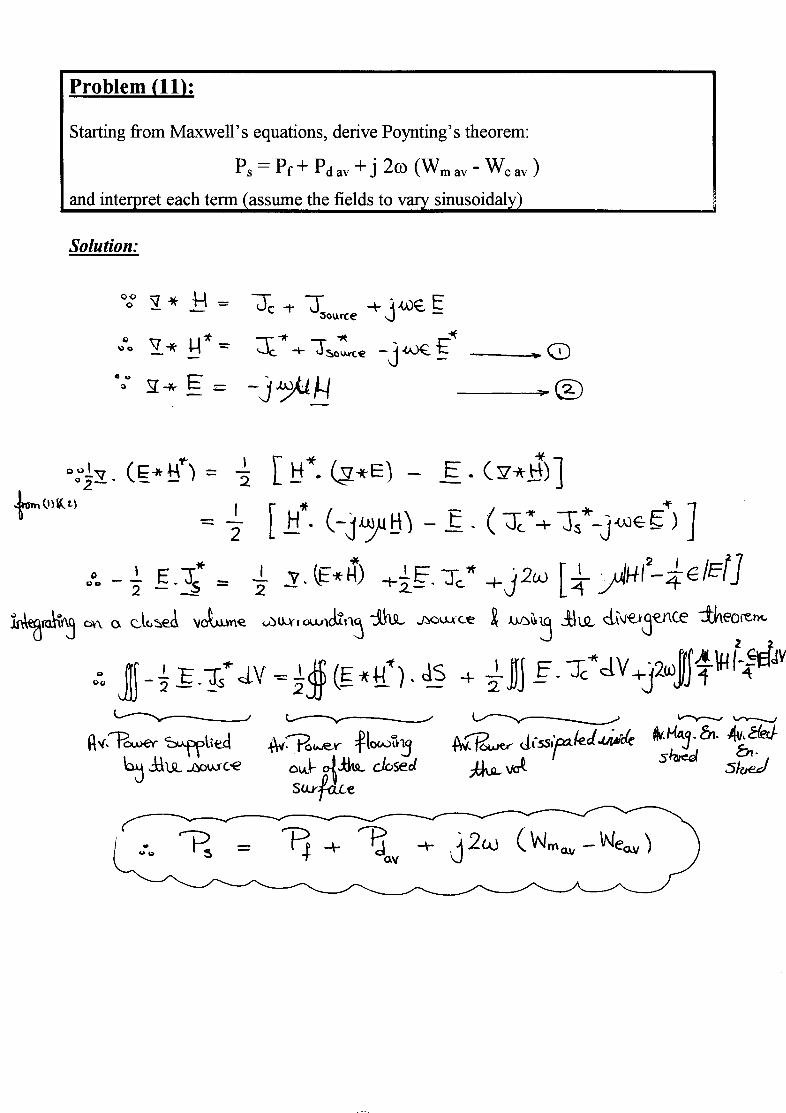
11. Starting from Maxwell’s equations, derive Poynting’s theorem:
Ps = Pf + Pd av + j 2ω (Wm av - We av )
and interpret each term (assume the fields to vary sinusoidaly)
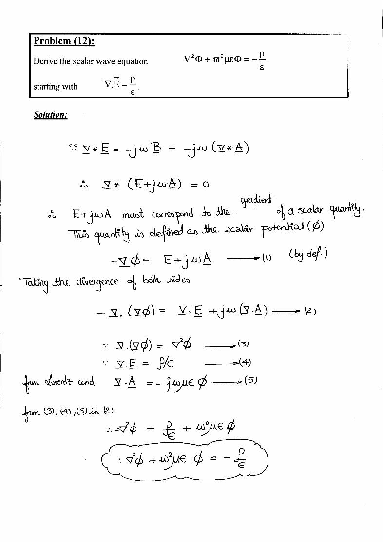
12. Derive the scalar wave equation ερ
−=Φµεϖ+Φ∇ 22
starting with ερ
=∇ E. .
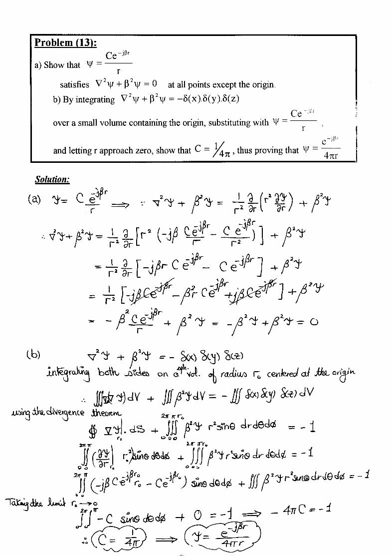
13. a) Show that r
Ce rjβ−
=ψ
satisfies 022 =ψβ+ψ∇ at all points except the origin.
b) By integrating )z().y().x(22 δδδ−=ψβ+ψ∇
over a small volume containing the origin, substituting with r
Ce rjβ−
=ψ ,
and letting r approach zero, show that π= 41C , thus proving that
r4
e rj
π=ψ
β−
B e st W ish e s,
P r o f. N a g d a El-M e n y a w y
E n g . M a g e d G h o n e i m a
2 - 1
Ain Shams UniversityFaculty of Engineering
Electronics and Comm. Eng. Dept.
Antennas4th Year
2000/2001 2nd Semester
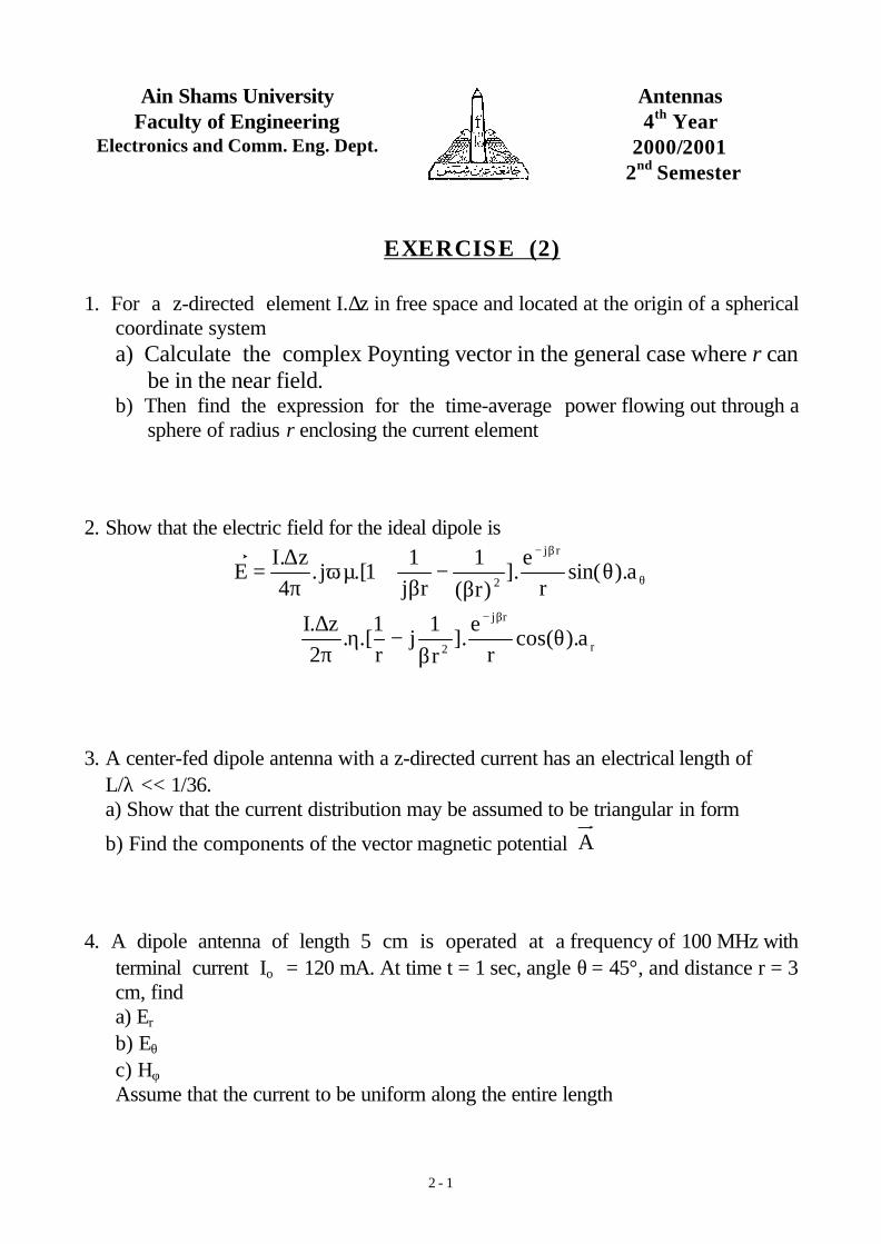
EXERCISE (2)
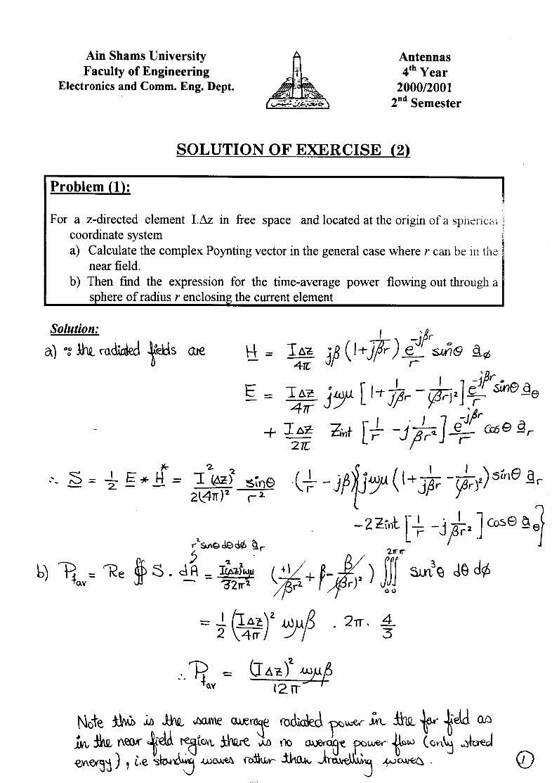
1. For a z-directed element I.∆z in free space and located at the origin of a sphericalcoordinate system a) Calculate the complex Poynting vector in the general case where r can
be in the near field.b) Then find the expression for the time-average power flowing out through a
sphere of radius r enclosing the current element
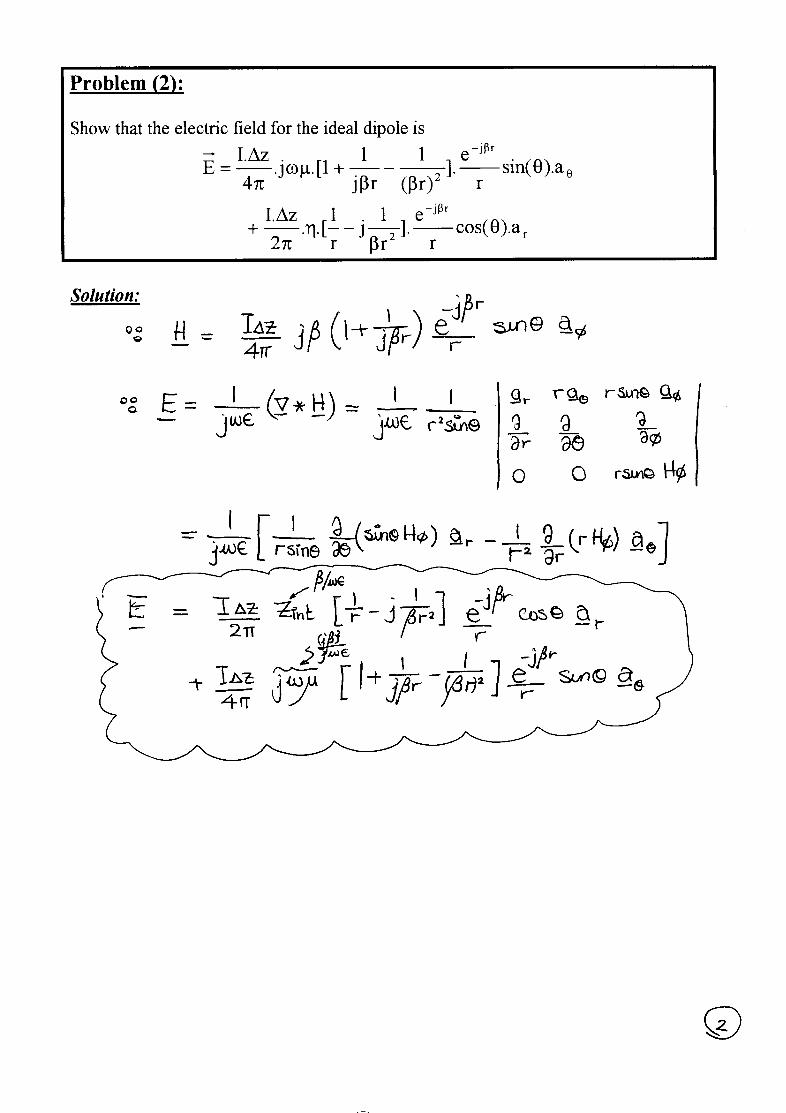
2. Show that the electric field for the ideal dipole is
θ
β−
θβ
−β
+ωµπ∆
= a).sin(r
e].
)r(
1rj
11.[j.
4z.I
Erj
2
r
rj
2a).cos(
re
].r
1j
r1
.[.2
z.Iθ
β−η
π∆
+β−
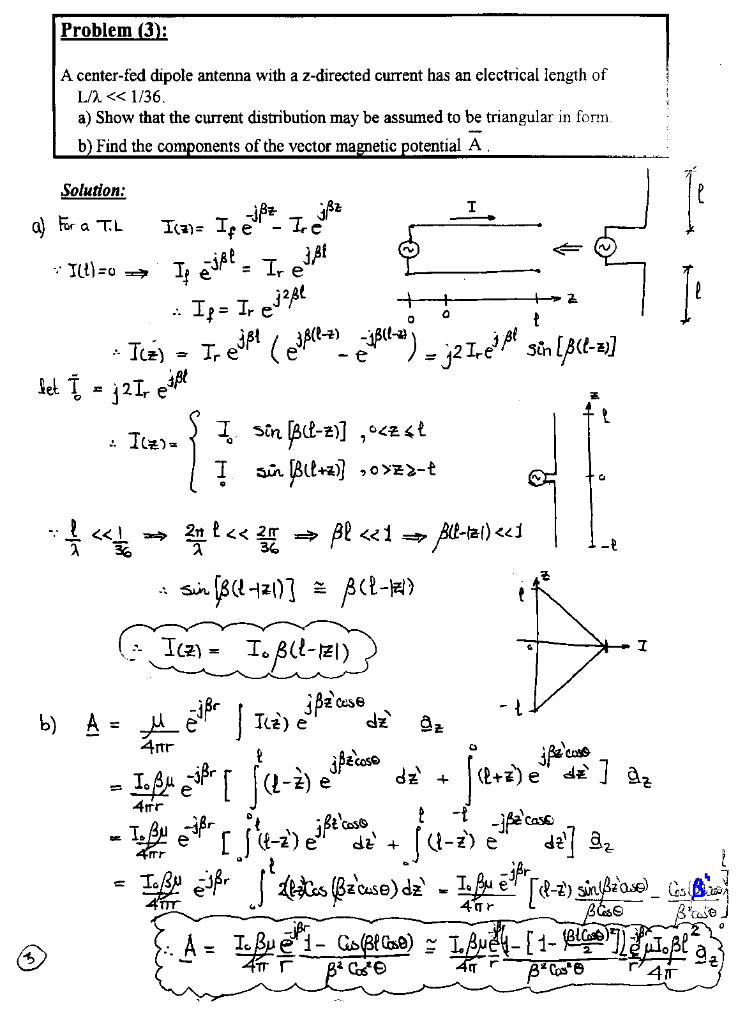
3. A center-fed dipole antenna with a z-directed current has an electrical length ofL/λ << 1/36.a) Show that the current distribution may be assumed to be triangular in form
b) Find the components of the vector magnetic potential A
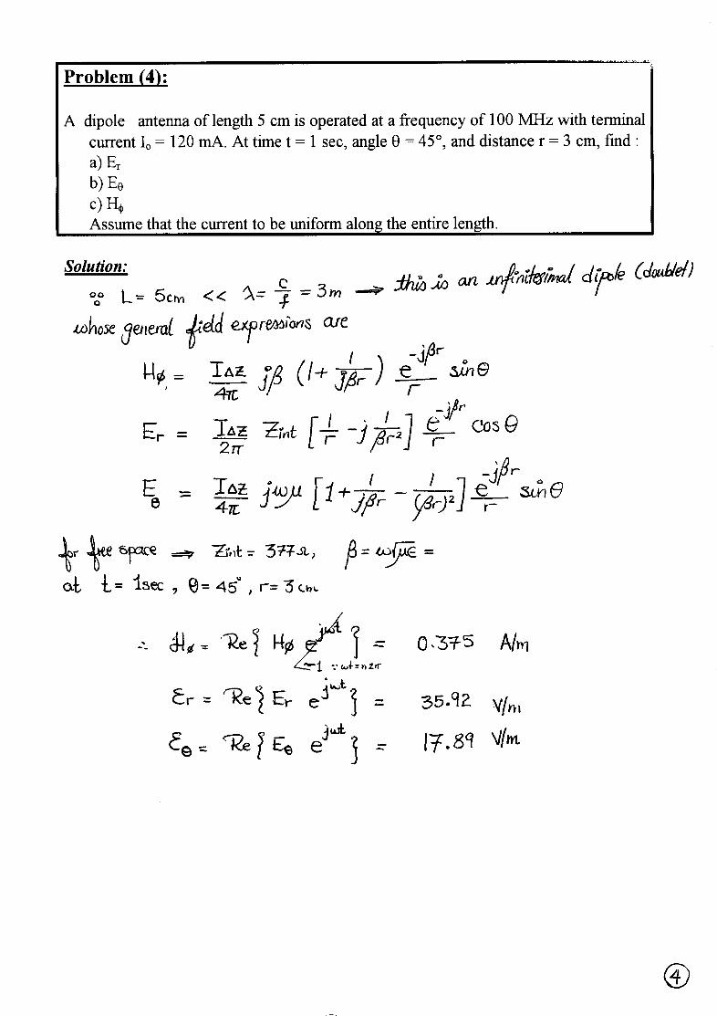
4. A dipole antenna of length 5 cm is operated at a frequency of 100 MHz withterminal current Io = 120 mA. At time t = 1 sec, angle θ = 45°, and distance r = 3cm, find a) Er
b) Eθ
c) Hφ
Assume that the current to be uniform along the entire length
2 - 2
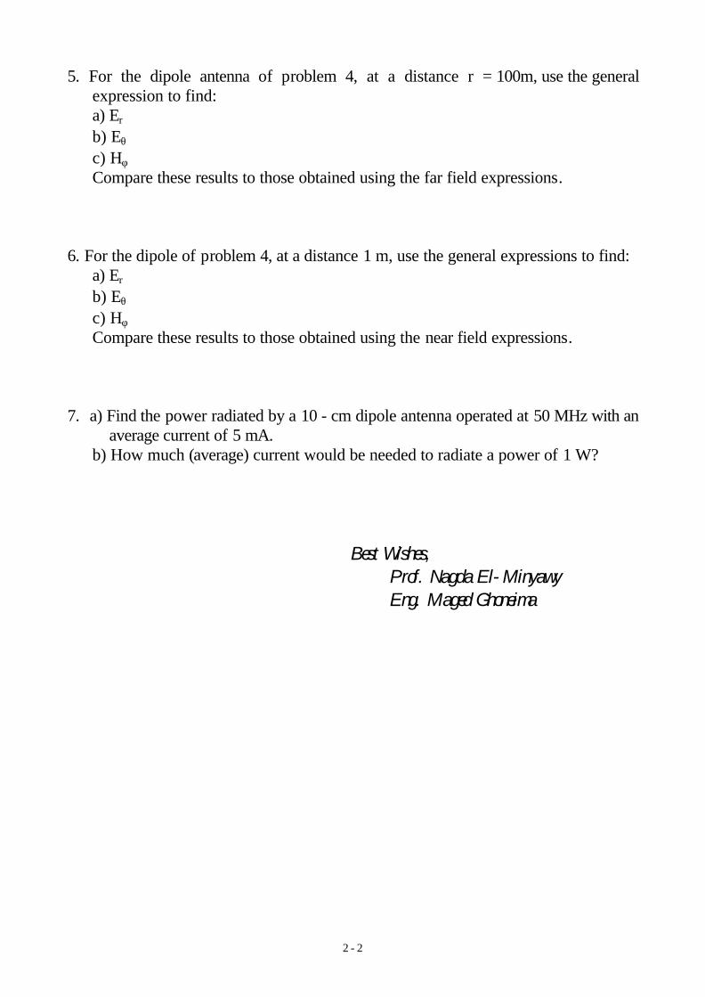
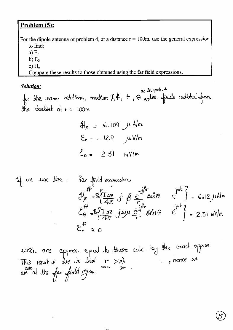
5. For the dipole antenna of problem 4, at a distance r = 100m, use the generalexpression to find:a) Er
b) Eθ
c) Hφ
Compare these results to those obtained using the far field expressions.
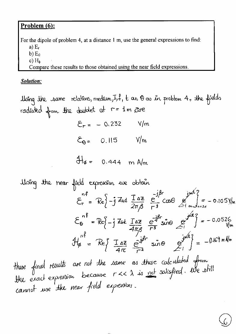
6. For the dipole of problem 4, at a distance 1 m, use the general expressions to find:a) Er
b) Eθ
c) Hφ
Compare these results to those obtained using the near field expressions.
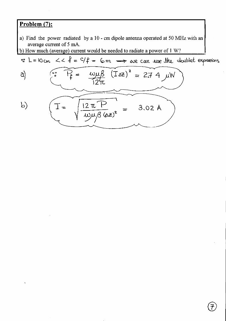
7. a) Find the power radiated by a 10 - cm dipole antenna operated at 50 MHz with anaverage current of 5 mA.
b) How much (average) current would be needed to radiate a power of 1 W?
Best Wishes,Prof. Nagda El-MinyawyEng. Maged Ghoneima
3 - 1
Ain Shams UniversityFaculty of Engineering
Electronics and Comm. Eng. Dept.
Antennas4th Year
2000/2001 2nd Semester
EXERCISE (3)
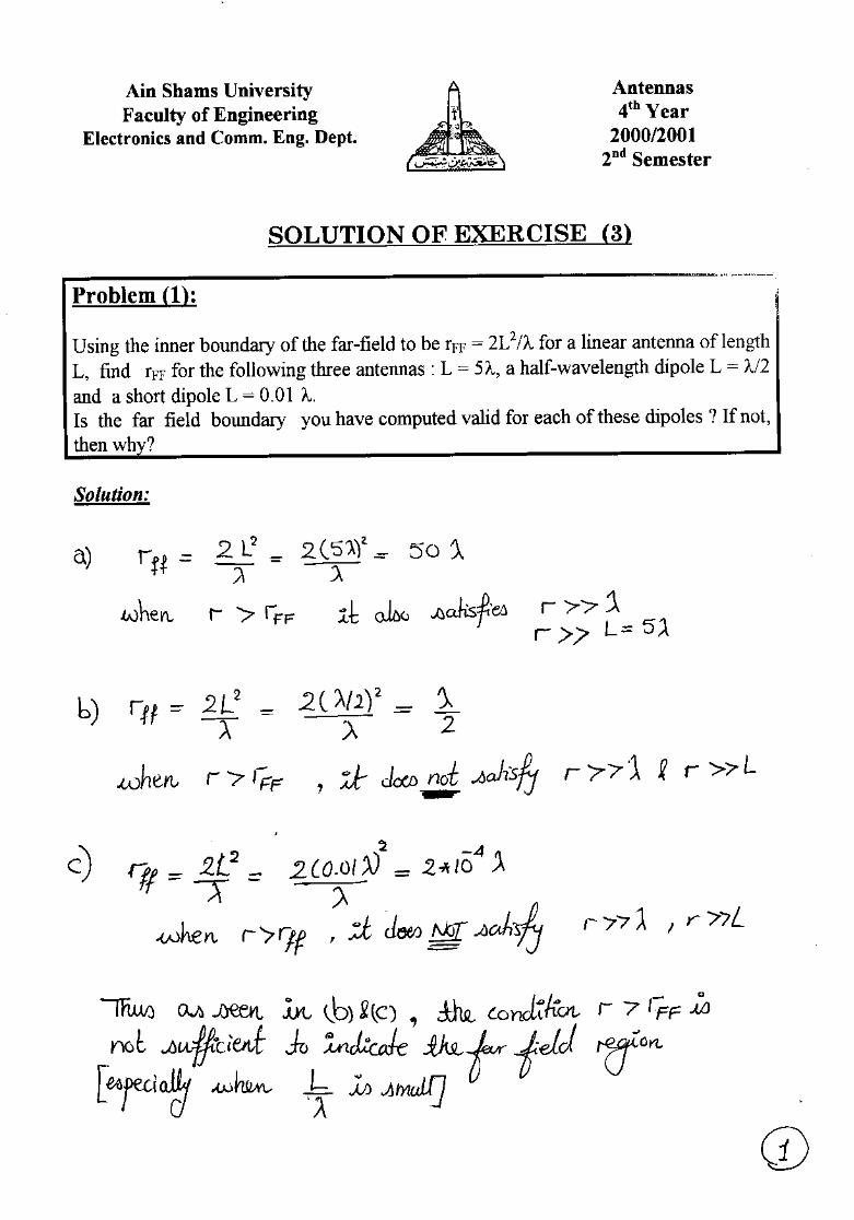
1. Using the inner boundary of the far-field to be rFF = 2L2/λ for a linear antenna oflength L, find rFF for the following three antennas : L = 5λ, a half-wavelengthdipole L = λ/2 and a short dipole L = 0.01 λ.Is the far field boundary you have computed valid for each of these dipoles ? Ifnot, then why?
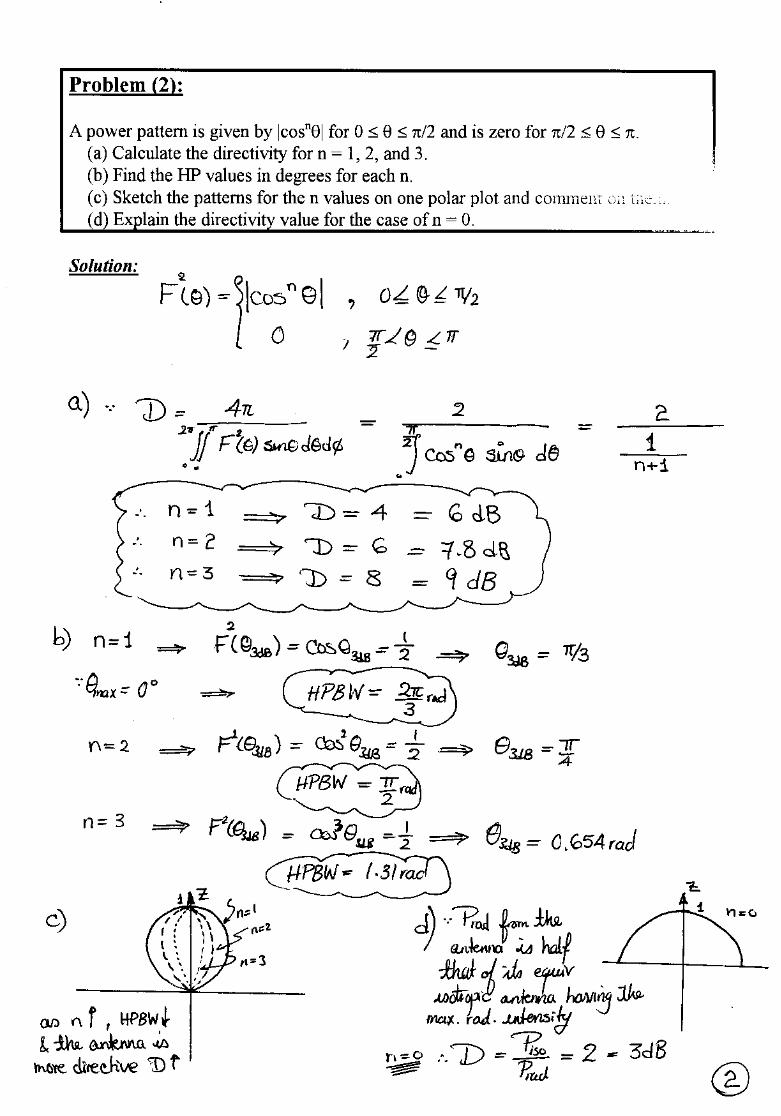
2. A power pattern is given by |cosnθ| for 0 ≤ θ ≤ π/2 and is zero for π/2 ≤ θ ≤ π.(a) Calculate the directivity for n = 1, 2, and 3.(b) Find the HP values in degrees for each n.(c) Sketch the patterns for the n values on one polar plot and comment on them.(d) Explain the directivity value for the case of n = 0.
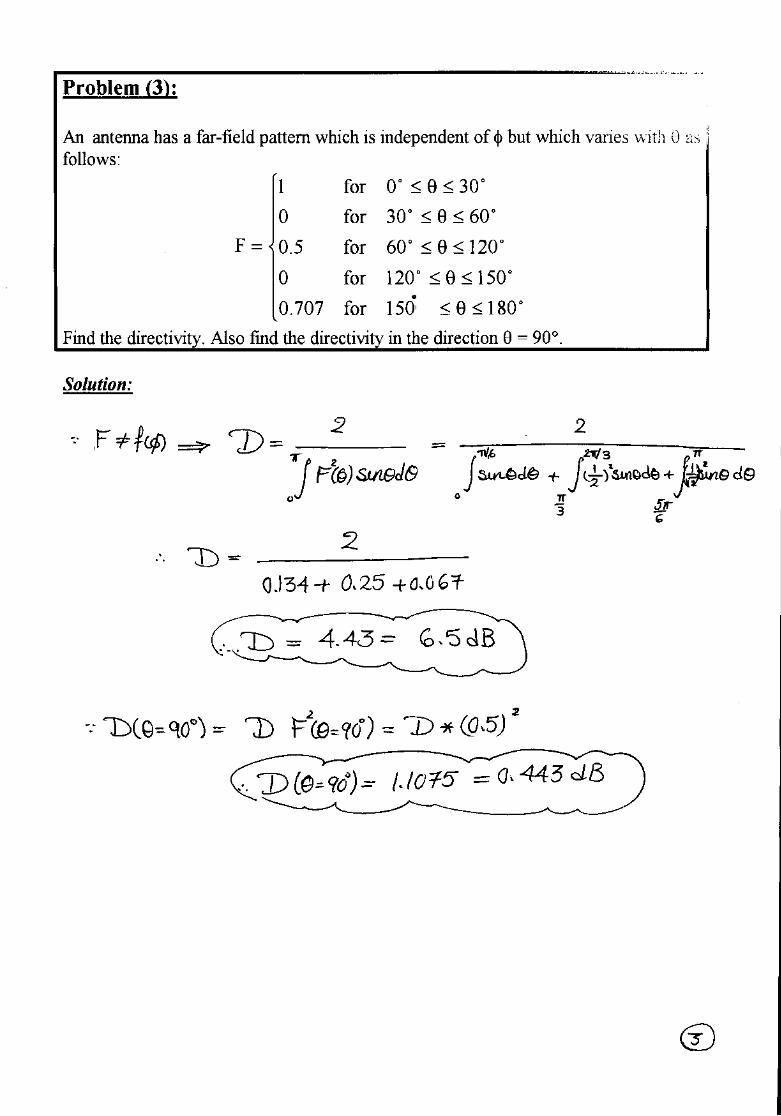
3. An antenna has a far-field pattern which is independent of φ but which varies with θas follows:
≤θ≤
≤θ≤≤θ≤
≤θ≤
≤θ≤
=
oo
oo
oo
oo
oo
1801500for707.0
150120for0
12060for5.0
6030for0
300for1
F
Find the directivity. Also find the directivity in the direction θ = 90°.
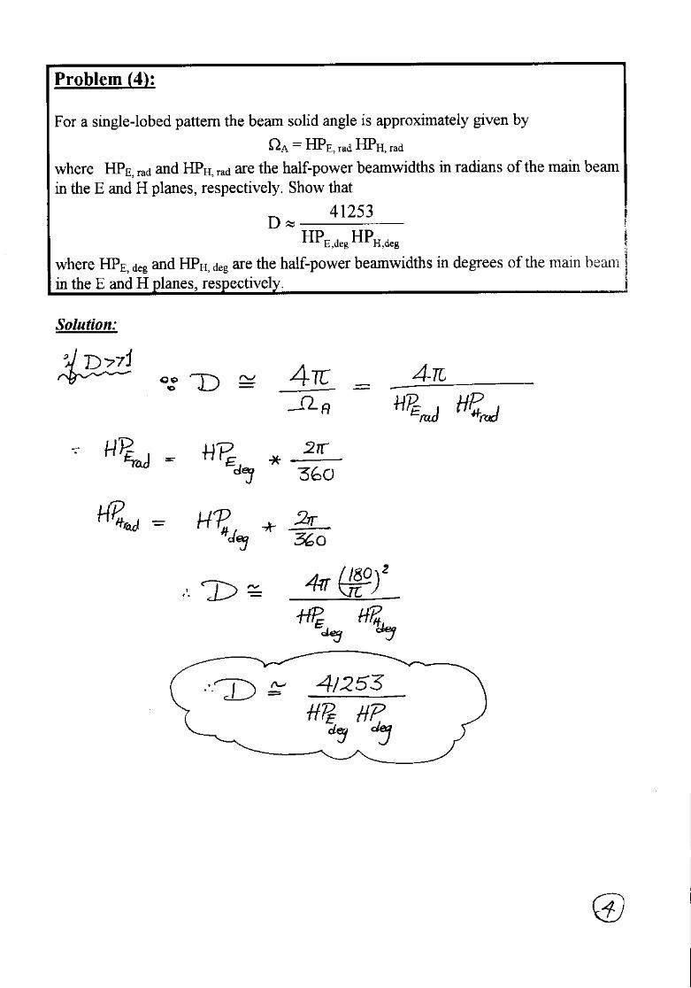
4. For a single-lobed pattern the beam solid angle is approximately given by
ΩA = HPE, rad HPH, rad
where HPE, rad and HPH, rad are the half-power beamwidths in radians of the mainbeam in the E and H planes, respectively. Show that
deg,Hdeg,E HPHP
41253D ≈
where HPE, deg and HPH, deg are the half-power beamwidths in degrees of the mainbeam in the E and H planes, respectively.
3 - 2
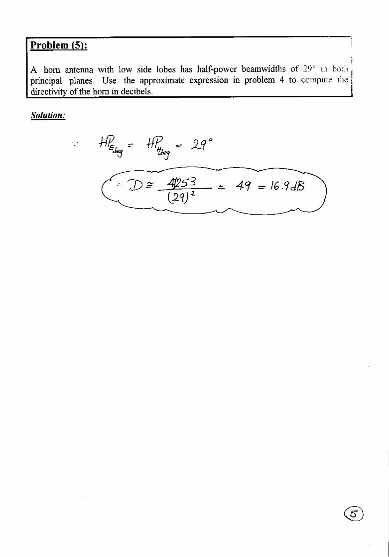
5. A horn antenna with low side lobes has half-power beamwidths of 29° in bothprincipal planes. Use the approximate expression in problem 4 to compute thedirectivity of the horn in decibels.
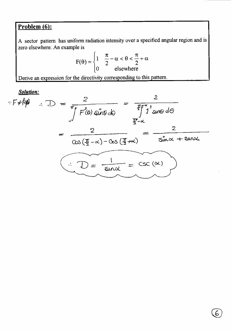
6. A sector pattern has uniform radiation intensity over a specified angular region andis zero elsewhere. An example is
α+
π<θ<α−
π=θ
elsewhere022
1)(F
Derive an expression for the directivity corresponding to this pattern.
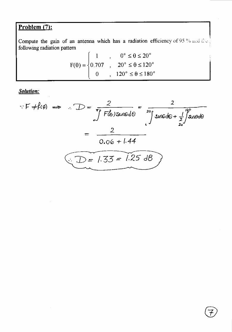
7. Compute the gain of an antenna which has a radiation efficiency of 95 % and thefollowing radiation pattern
≤θ≤≤θ≤
≤θ≤
=θoo
oo
oo
180120,0
12020,707.0
200,1
)(F
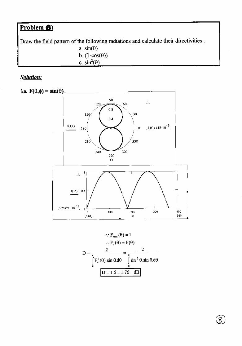
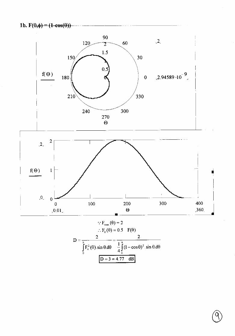
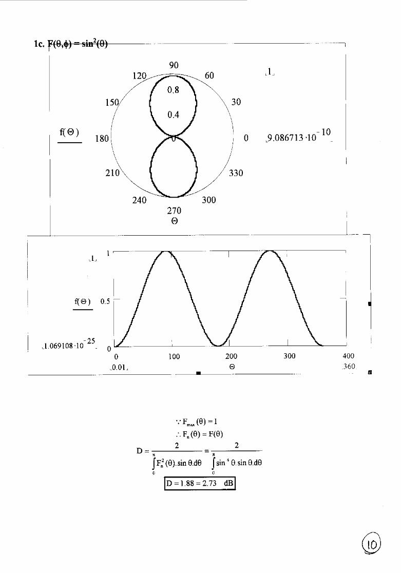
8. Draw the field pattern of the following radiations and calculate their directivities :a. sin(θ)b. (1-cos(θ))c. sin2(θ)
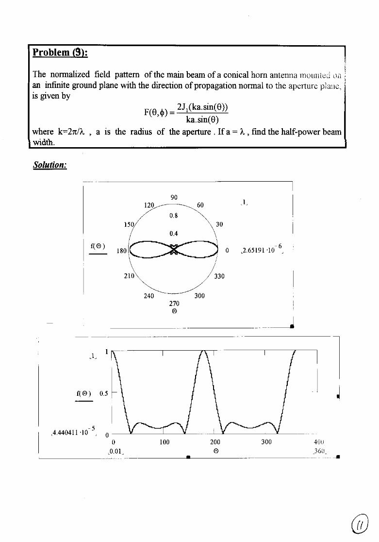
9. The normalized field pattern of the main beam of a conical horn antenna mountedon an infinite ground plane with the direction of propagation normal to the apertureplane, is given by
FJ ka
ka( , )
( .sin( ))
.sin( )θ φ θ
θ=
2 1
where k=2π/λ , a is the radius of the aperture . If a = λ , find the half-power beamwidth
10. Find the half-power beamwidth of the uniform line whose pattern factor f(θ) is
)cos().2
l(
)]cos().2
lsin[(
)(fθ
β
θβ
=θ, where β l = π
Best Wishes,Prof. Nagda El-MinyawyEng. Maged Ghoneima
4 - 1
Ain Shams UniversityFaculty of Engineering
Electronics and Comm. Eng. Dept.
Antennas4th Year
2000/2001 2nd Semester
EXERCISE (4)
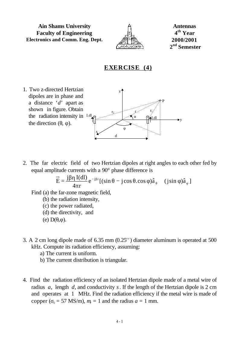
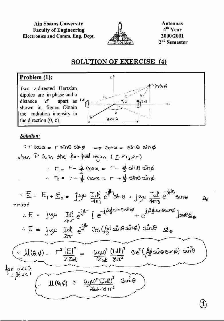
1. Two z-directed Hertziandipoles are in phase anda distance ‘d’ apart asshown in figure. Obtainthe radiation intensity inthe direction (θ, φ).
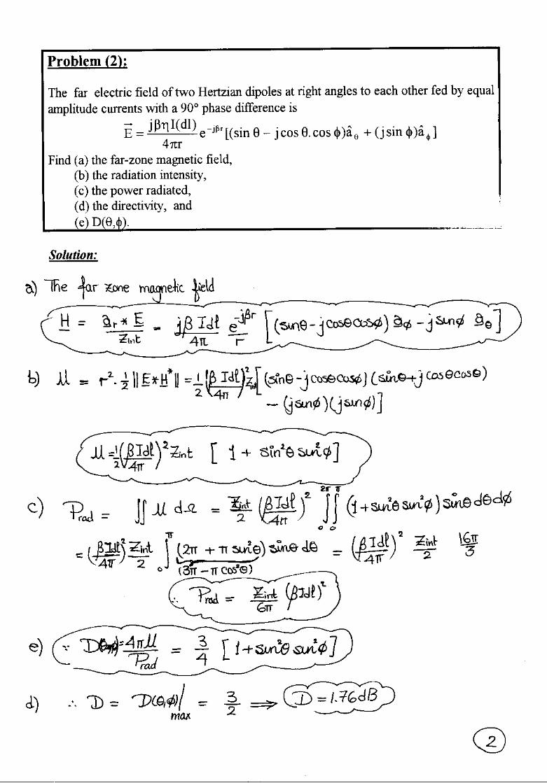
2. The far electric field of two Hertzian dipoles at right angles to each other fed byequal amplitude currents with a 90° phase difference is
]a)sinj(a)cos.cosj[(siner4
)dl(IjE rj
φθβ− φ+φθ−θ
πβη=
Find (a) the far-zone magnetic field,(b) the radiation intensity,(c) the power radiated,(d) the directivity, and(e) D(θ,φ).
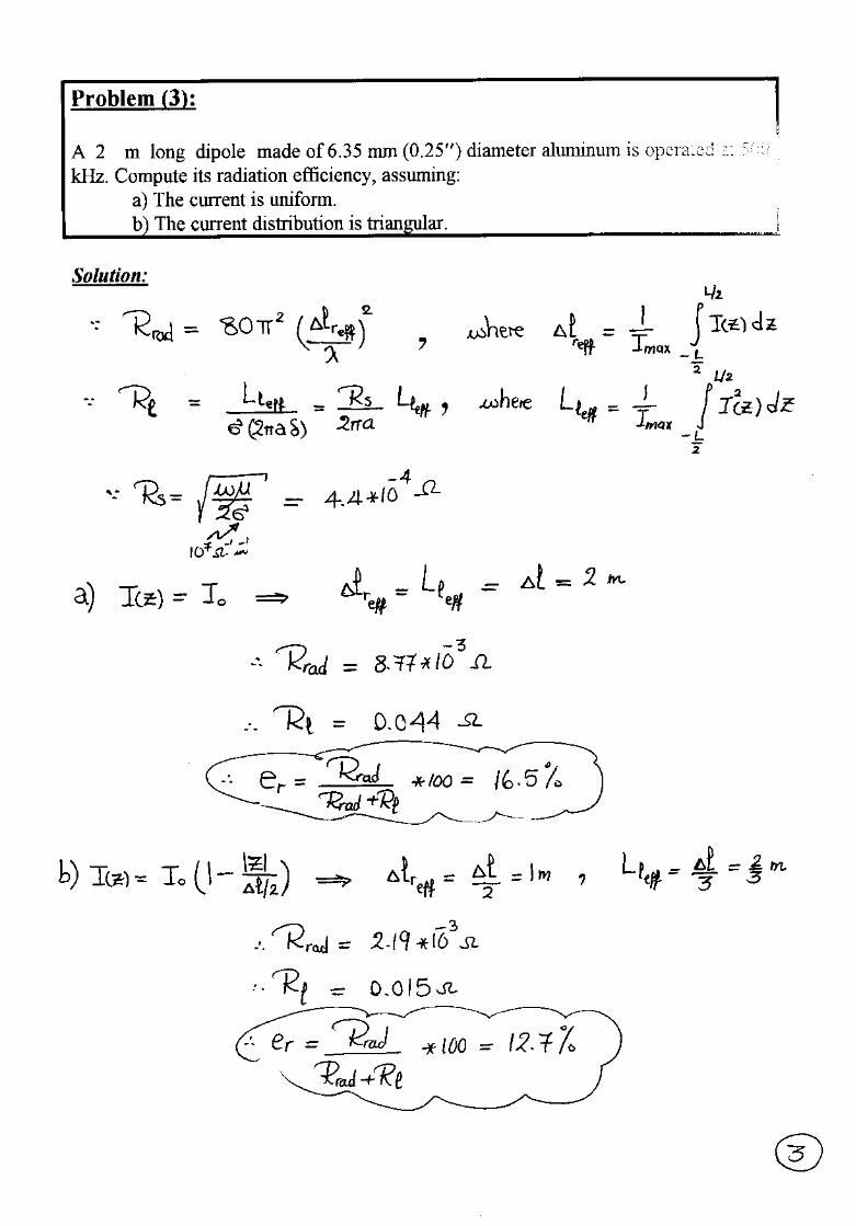
3. A 2 cm long dipole made of 6.35 mm (0.25′′) diameter aluminum is operated at 500kHz. Compute its radiation efficiency, assuming:
a) The current is uniform.b) The current distribution is triangular.
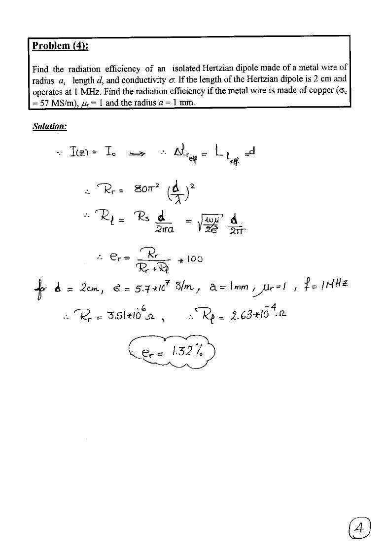
4. Find the radiation efficiency of an isolated Hertzian dipole made of a metal wire ofradius a, length d, and conductivity σ. If the length of the Hertzian dipole is 2 cmand operates at 1 MHz. Find the radiation efficiency if the metal wire is made ofcopper (σc = 57 MS/m), µr = 1 and the radius a = 1 mm.
P
αr
φ
r1r2I.dl
I.dl y
z
xd
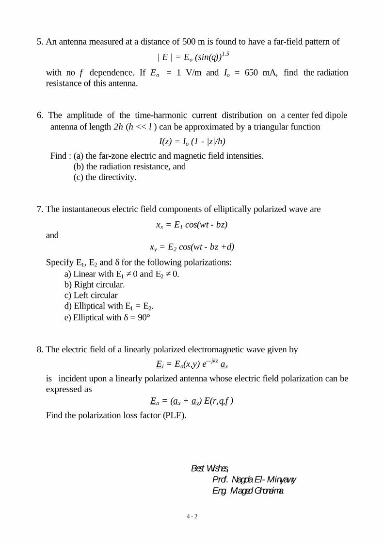
4 - 2
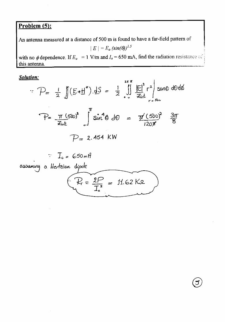
5. An antenna measured at a distance of 500 m is found to have a far-field pattern of
| E | = Eo (sin(θ))1.5
with no φ dependence. If Eo = 1 V/m and Io = 650 mA, find the radiationresistance of this antenna.
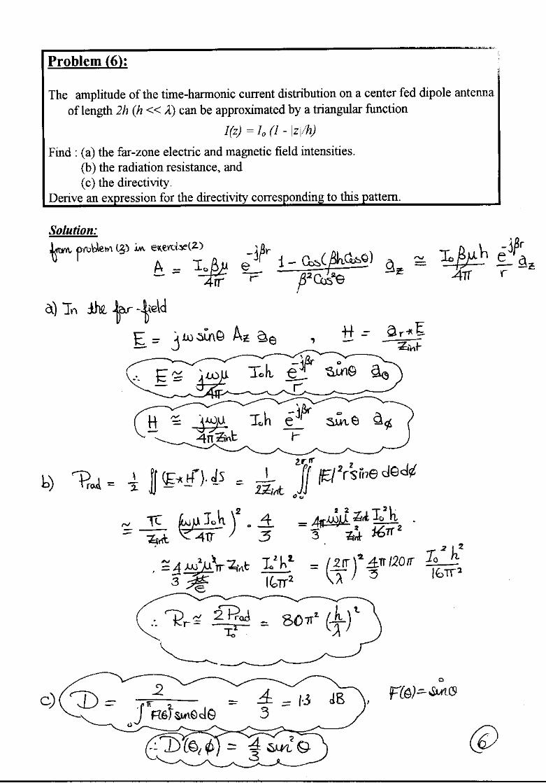
6. The amplitude of the time-harmonic current distribution on a center fed dipoleantenna of length 2h (h << λ) can be approximated by a triangular function
I(z) = Io (1 - |z|/h)
Find : (a) the far-zone electric and magnetic field intensities.(b) the radiation resistance, and(c) the directivity.
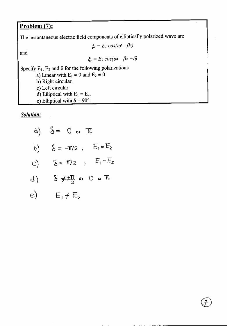
7. The instantaneous electric field components of elliptically polarized wave are
ξx = E1 cos(ωt - βz)and
ξy = E2 cos(ωt - βz +δ)
Specify E1, E2 and δ for the following polarizations:a) Linear with E1 ≠ 0 and E2 ≠ 0.b) Right circular.c) Left circulard) Elliptical with E1 = E2.e) Elliptical with δ = 90°
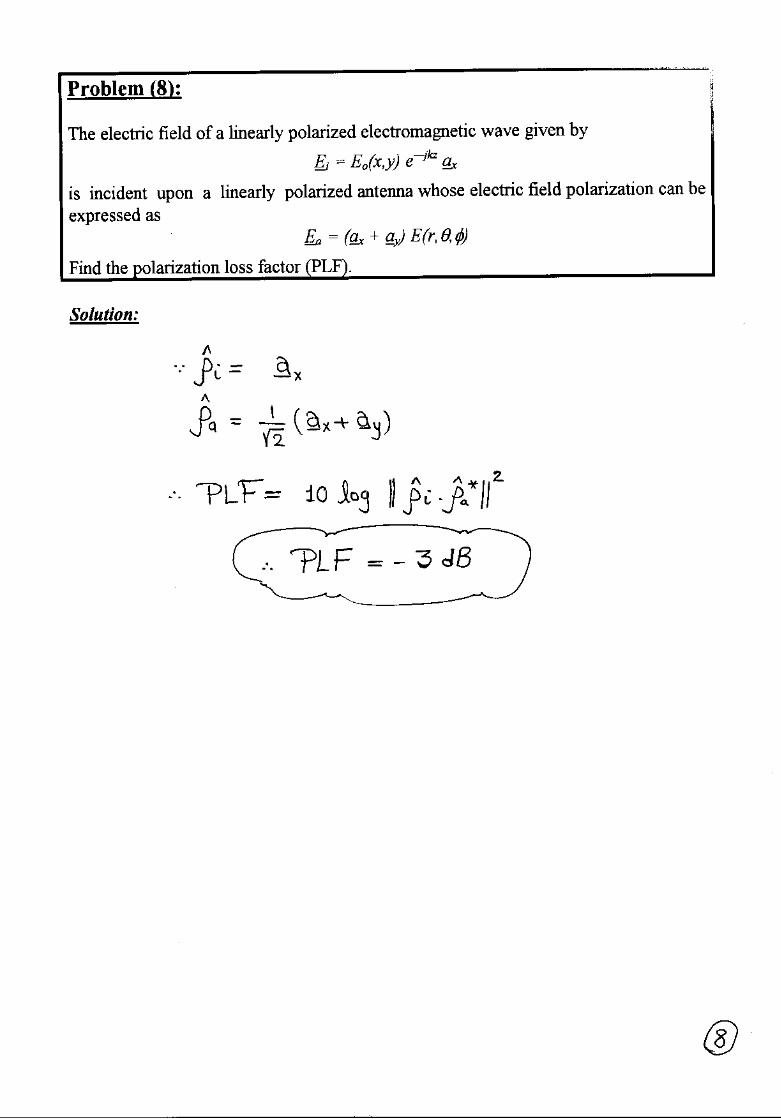
8. The electric field of a linearly polarized electromagnetic wave given by
Ei = Eo(x,y) e—jkz ax
is incident upon a linearly polarized antenna whose electric field polarization can beexpressed as
Ea = (ax + ay) E(r,θ,φ)
Find the polarization loss factor (PLF).
Best Wishes,Prof. Nagda El-MinyawyEng. Maged Ghoneima
5 - 1
Ain Shams UniversityFaculty of Engineering
Electronics and Comm. Eng. Dept.
Antennas4th Year
2000/2001 2nd Semester
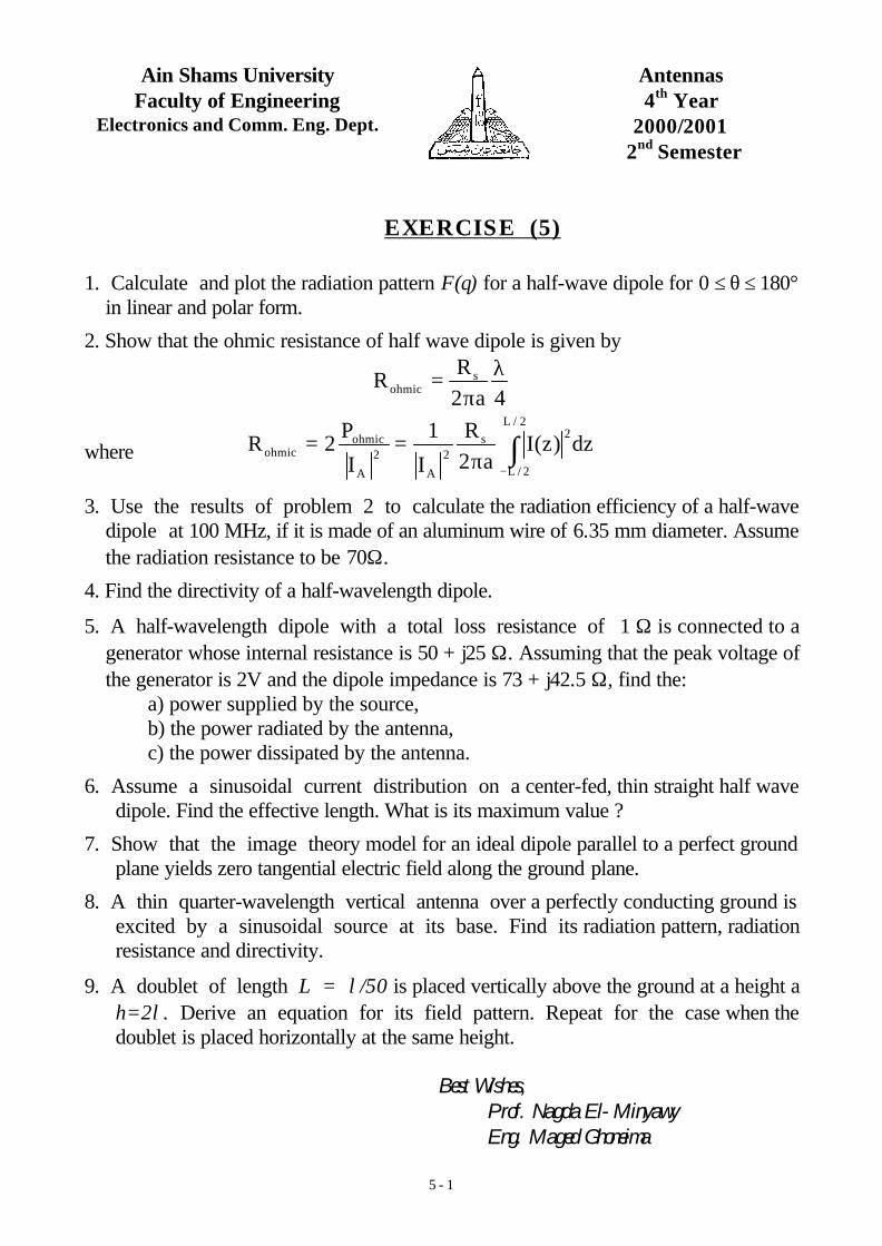
EXERCISE (5)
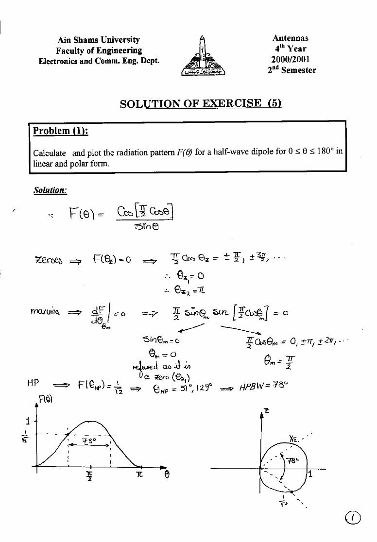
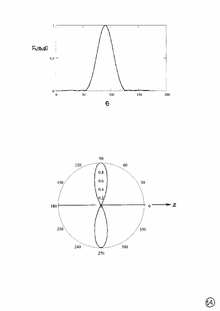
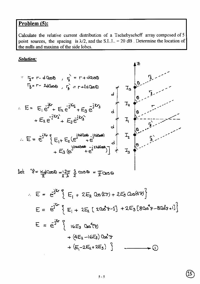
1. Calculate and plot the radiation pattern F(θ) for a half-wave dipole for 0 ≤ θ ≤ 180°in linear and polar form.
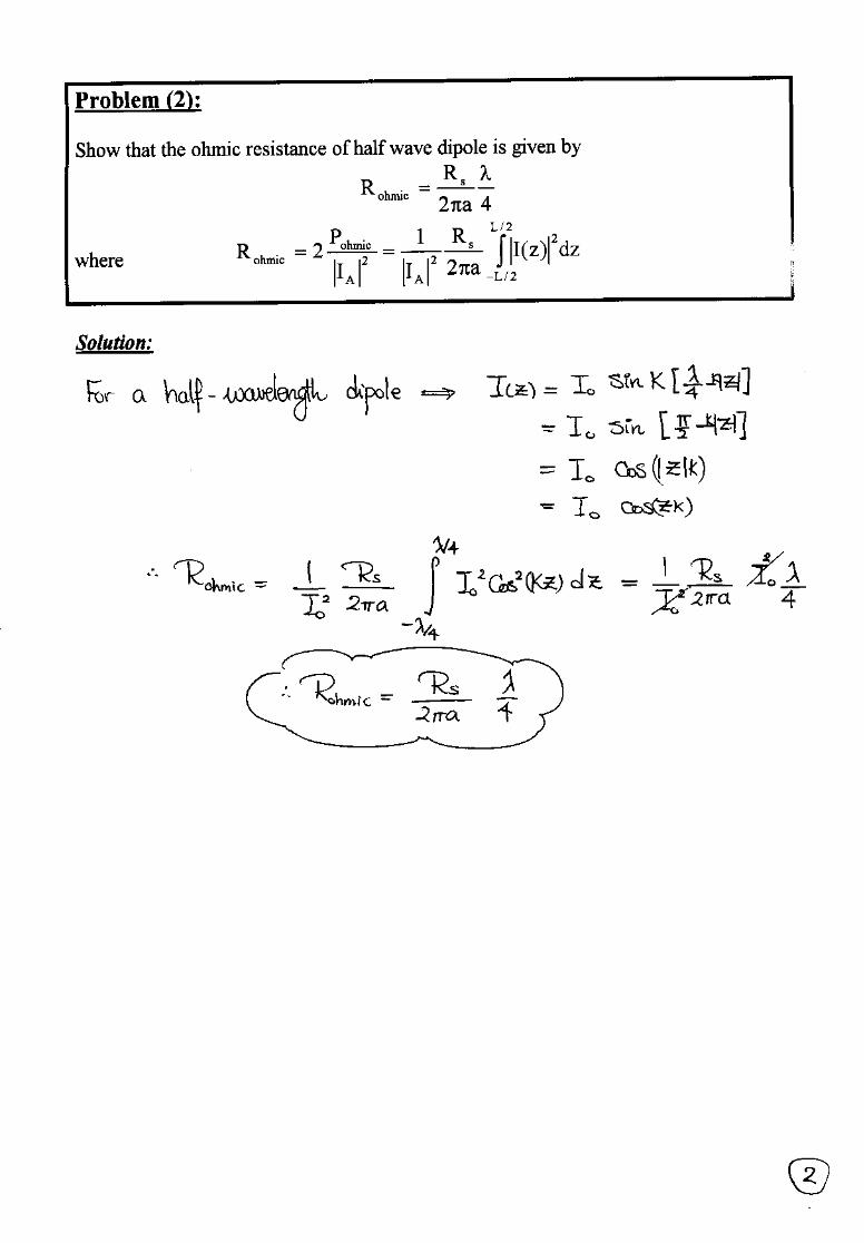
2. Show that the ohmic resistance of half wave dipole is given by
4a2R
R sohmic
λπ
=
where dz)z(Ia2
R
I
1
I
P2R
2/L
2/L
2s2
A
2
A
ohmicohmic ∫
−π==
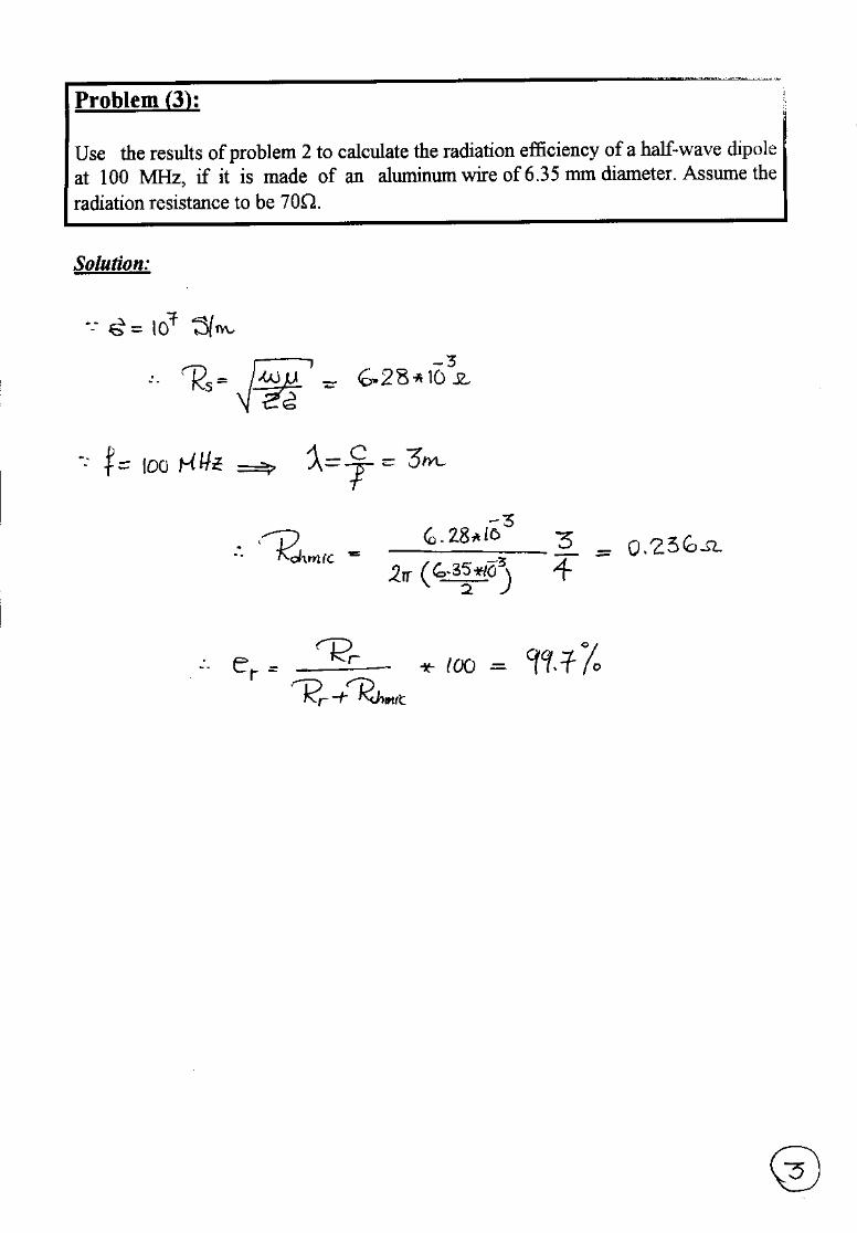
3. Use the results of problem 2 to calculate the radiation efficiency of a half-wavedipole at 100 MHz, if it is made of an aluminum wire of 6.35 mm diameter. Assumethe radiation resistance to be 70Ω.
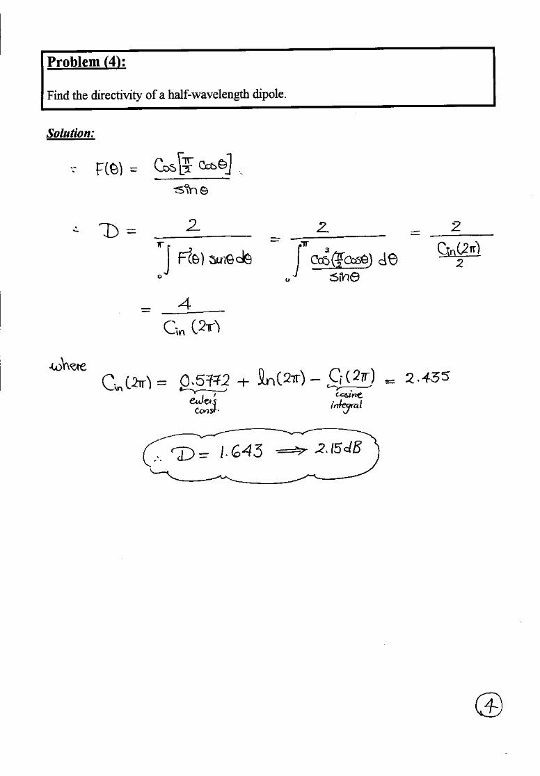
4. Find the directivity of a half-wavelength dipole.
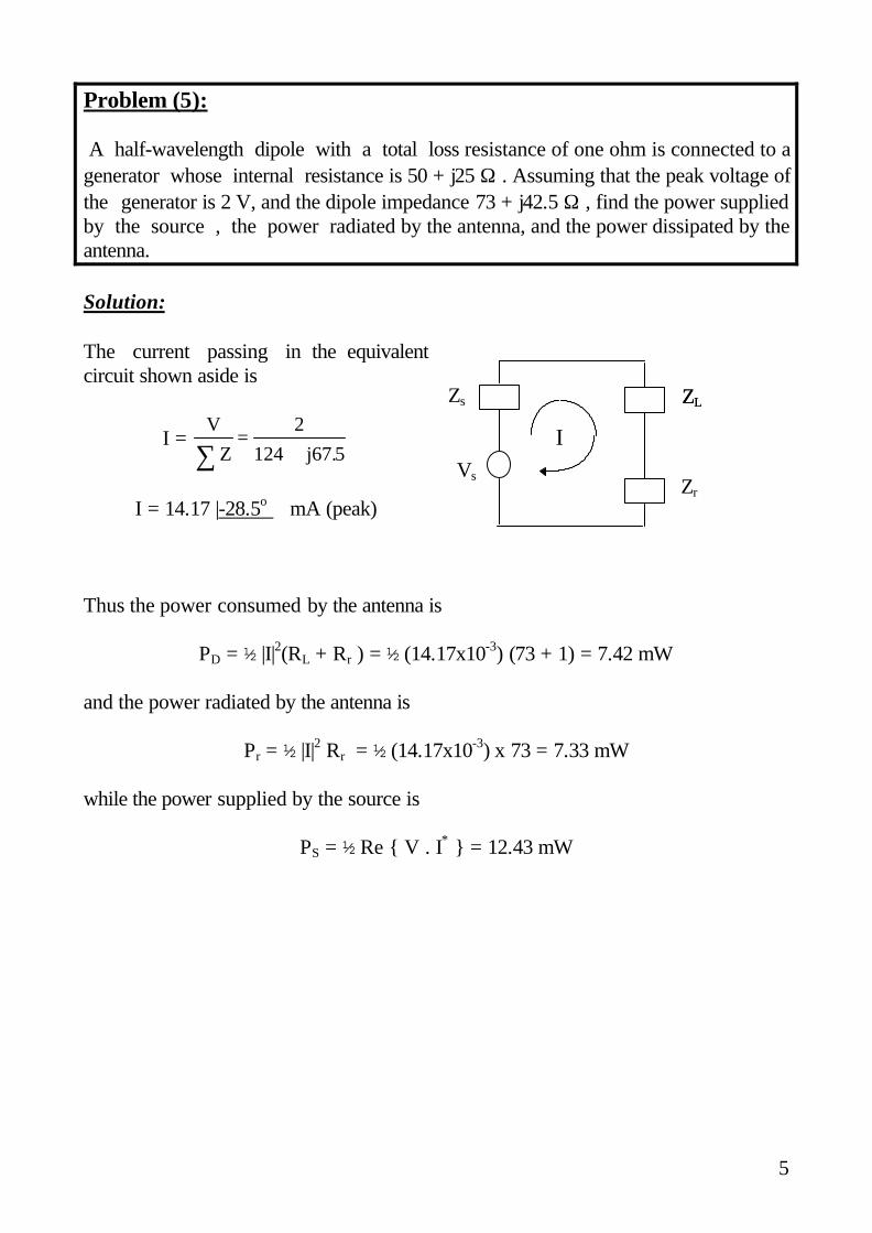
5. A half-wavelength dipole with a total loss resistance of 1 Ω is connected to agenerator whose internal resistance is 50 + j25 Ω. Assuming that the peak voltage ofthe generator is 2V and the dipole impedance is 73 + j42.5 Ω, find the:
a) power supplied by the source,b) the power radiated by the antenna,c) the power dissipated by the antenna.
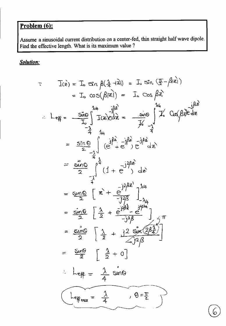
6. Assume a sinusoidal current distribution on a center-fed, thin straight half wavedipole. Find the effective length. What is its maximum value ?
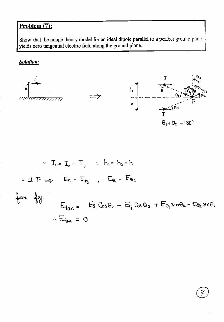
7. Show that the image theory model for an ideal dipole parallel to a perfect groundplane yields zero tangential electric field along the ground plane.
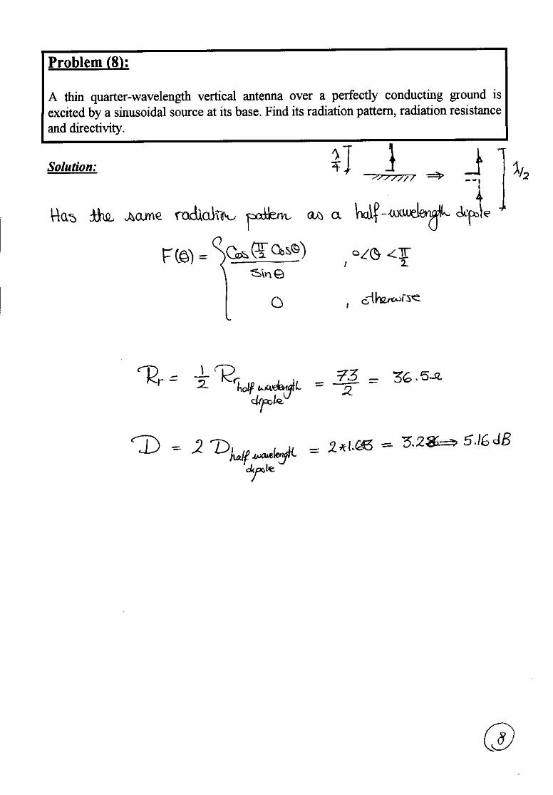
8. A thin quarter-wavelength vertical antenna over a perfectly conducting ground isexcited by a sinusoidal source at its base. Find its radiation pattern, radiationresistance and directivity.
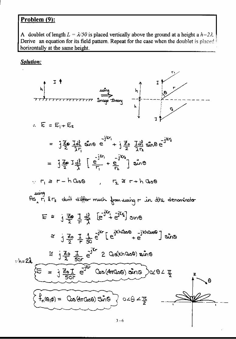
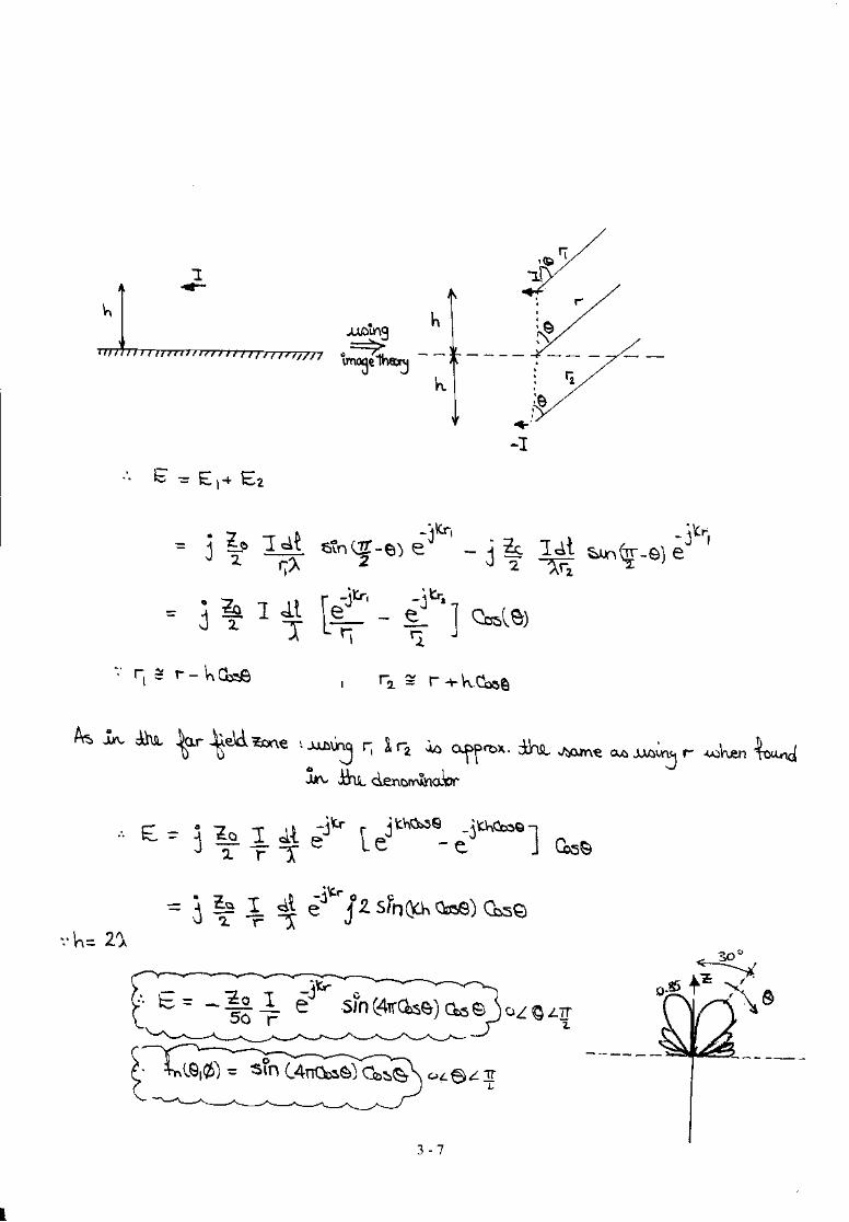
9. A doublet of length L = λ/50 is placed vertically above the ground at a height ah=2λ. Derive an equation for its field pattern. Repeat for the case when thedoublet is placed horizontally at the same height.
Best Wishes,Prof. Nagda El-MinyawyEng. Maged Ghoneima
5
Problem (5):
A half-wavelength dipole with a total loss resistance of one ohm is connected to agenerator whose internal resistance is 50 + j25 Ω . Assuming that the peak voltage ofthe generator is 2 V, and the dipole impedance 73 + j42.5 Ω , find the power suppliedby the source , the power radiated by the antenna, and the power dissipated by theantenna.
Solution:
The current passing in the equivalentcircuit shown aside is
I = V
Z j∑=
+2
124 67 5.
I = 14.17 |-28.5o mA (peak)
Thus the power consumed by the antenna is
PD = ½ |I|2(RL + Rr ) = ½ (14.17x10⁻³) (73 + 1) = 7.42 mW
and the power radiated by the antenna is
Pr = ½ |I|2 Rr = ½ (14.17x10-3) x 73 = 7.33 mW
while the power supplied by the source is
PS = ½ Re V . I* = 12.43 mW
Vs
Zs ZLZL
Zr
I
6 - 1
Ain Shams UniversityFaculty of Engineering
Electronics and Comm. Eng. Dept.
Antennas4th Year
2000/2001 2nd Semester
EXERCISE (6)
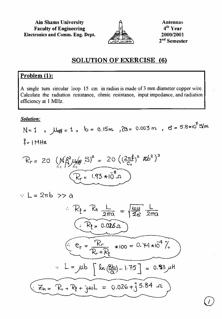
1. A single turn circular loop 15 cm in radius is made of 3 mm diameter copper wire.Calculate the radiation resistance, ohmic resistance, input impedance, and radiationefficiency at 1 MHz.
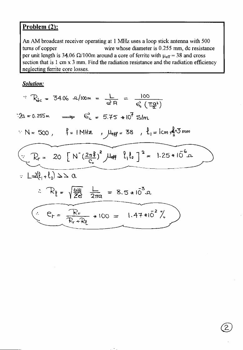
2. An AM broadcast receiver operating at 1 MHz uses a loop stick antenna with 500turns of copper (σ = 5.7 x 10⁷ S/m) wire whose diameter is 0.255 mm, dcresistance per unit length is 32.06 Ω/100m around a core of ferrite with µeff = 38and cross section that is 1 cm x 3 mm. Find the radiation resistance and theradiation efficiency neglecting ferrite core losses.
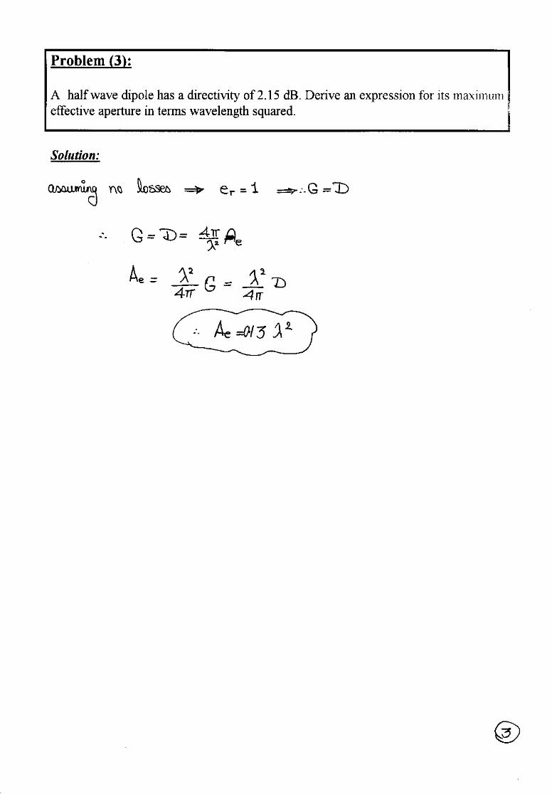
3. A half wave dipole has a directivity of 2.15 dB. Derive an expression for itsmaximum effective aperture in terms wavelength squared.
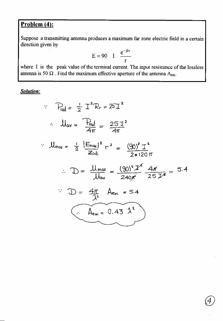
4. Suppose a transmitting antenna produces a maximum far zone electric field in acertain direction given by
re
I90Erjβ−
=
where I is the peak value of the terminal current. The input resistance of thelossless antenna is 50 . Find the maximum effective aperture of the antenna Aem.
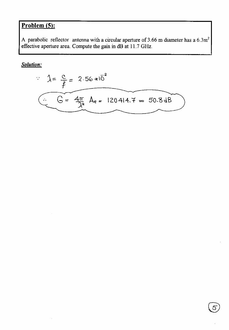
5. A parabolic reflector antenna with a circular aperture of 3.66 m diameter has a6.3m2 effective aperture area. Compute the gain in dB at 11.7 GHz.
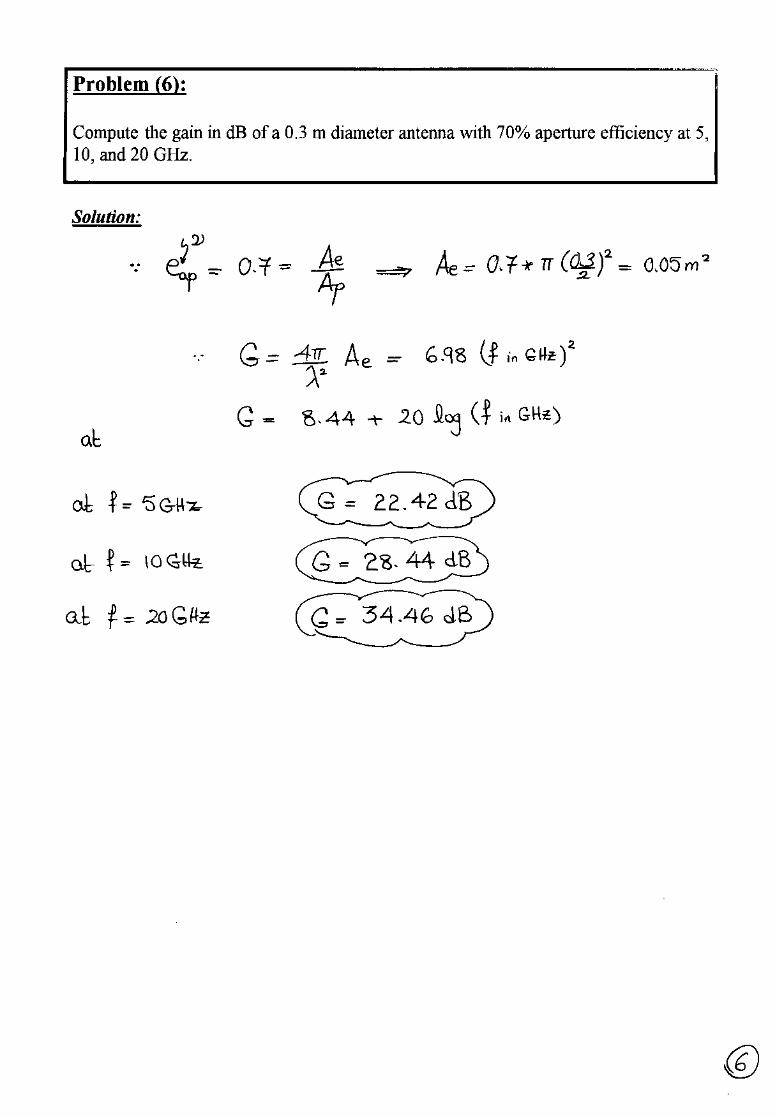
6. Compute the gain in dB of a 0.3 m diameter antenna with 70% aperture areefficiency at 5, 10, and 20 GHz.
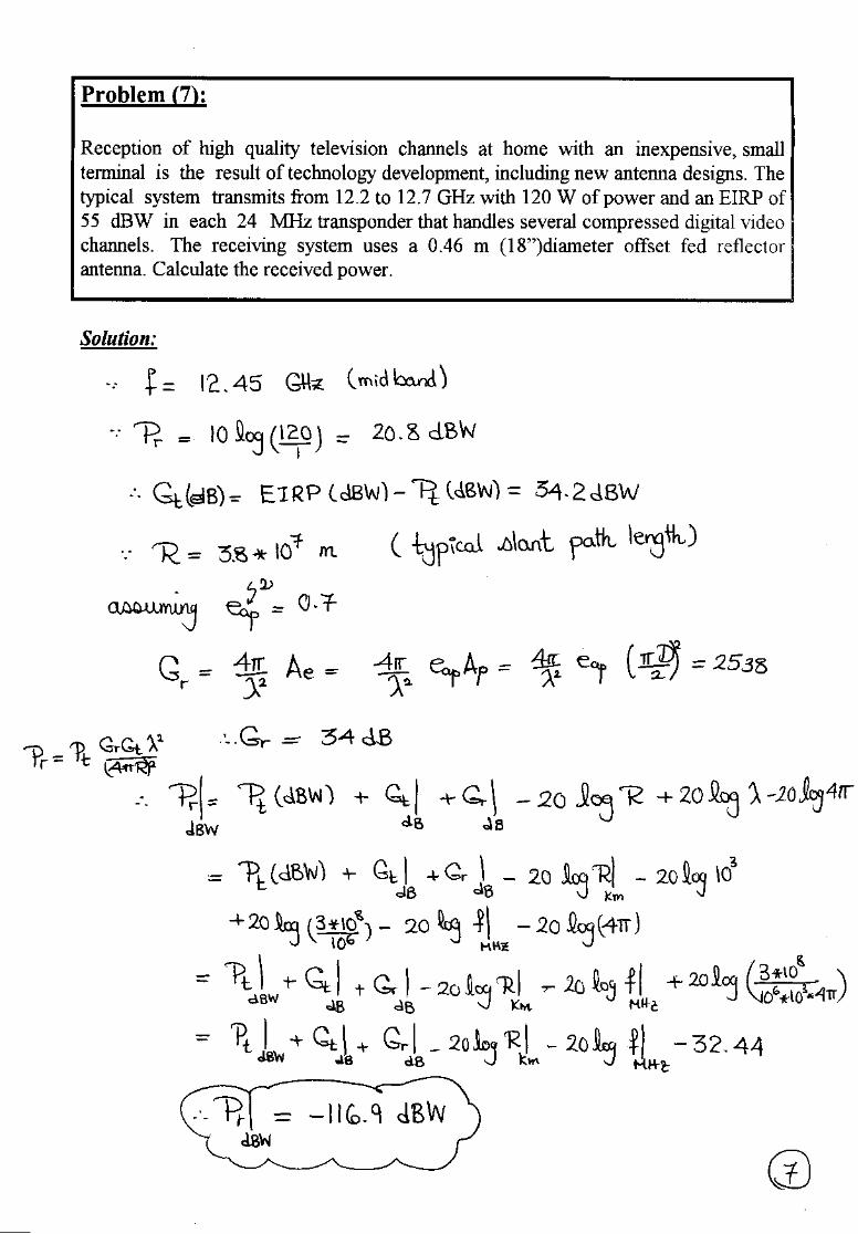
7. Reception of high quality television channels at home with an inexpensive, smallterminal is the result of technology development, including new antenna designs.The typical system transmits from 12.2 to 12.7 GHz with 120 W of power and anEIRP of 55 dBW in each 24 MHz transponder that handles several compresseddigital video channels. The receiving system uses a 0.46 m (18”)diameter offsetfed reflector antenna. Calculate the received power.
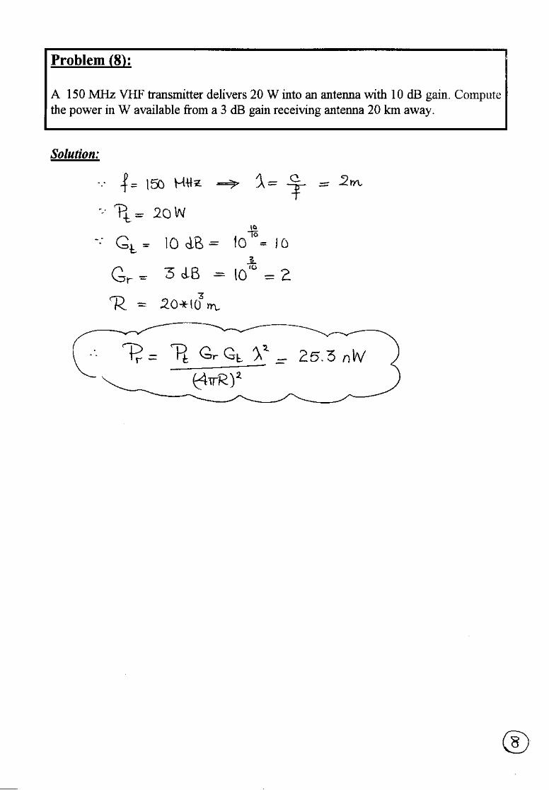
8. A 150 MHz VHF transmitter delivers 20 W into an antenna with 10 dB gain.Compute the power in W available from a 3 dB gain receiving antenna 20 kmaway.
6 - 2
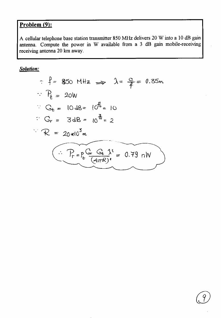
9. A cellular telephone base station transmitter 850 MHz delivers 20 W into a 10 dBgain antenna. Compute the power in W available from a 3 dB gain mobile-receivingreceiving antenna 20 km away.
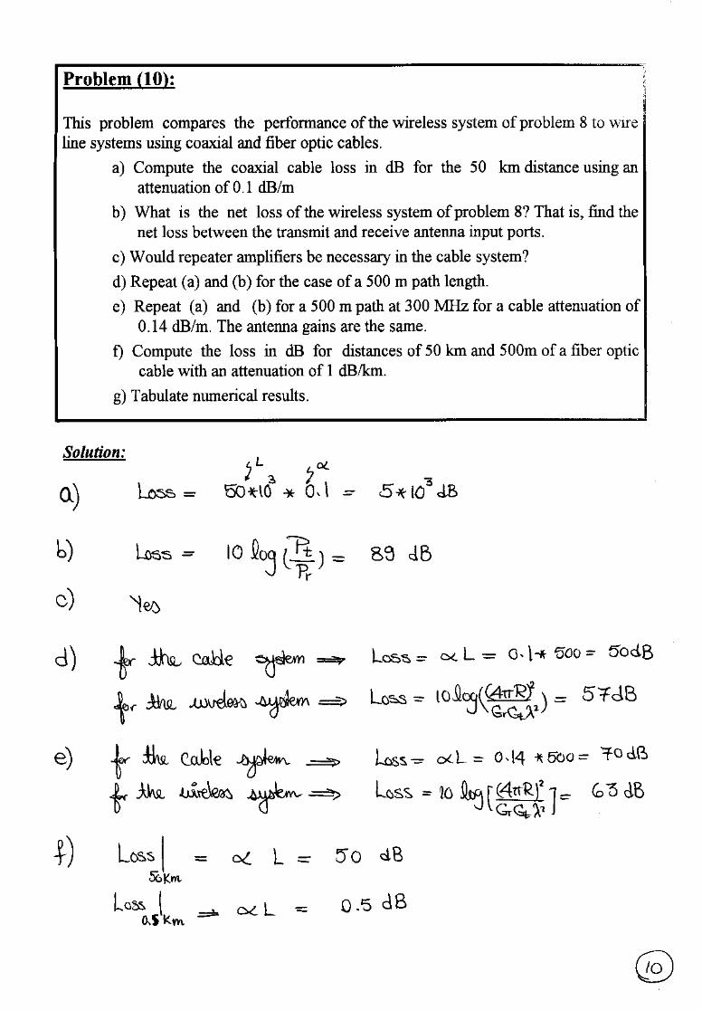
10. This problem compares the performance of the wireless system of problem 8 towire line systems using coaxial and fiber optic cables.
a) Compute the coaxial cable loss in dB for the 50 km distance using anattenuation of 0.1 dB/m
b) What is the net loss of the wireless system of problem 8? That is, find thenet loss between the transmit and receive antenna input ports.
c) Would repeater amplifiers be necessary in the cable system?
d) Repeat (a) and (b) for the case of a 500 m path length.
e) Repeat (a) and (b) for a 500 m path at 300 MHz for a cable attenuation of0.14 dB/m. The antenna gains are the same.
f) Compute the loss in dB for distances of 50 km and 500m of a fiber opticcable with an attenuation of 1 dB/km.
g) Tabulate numerical results.
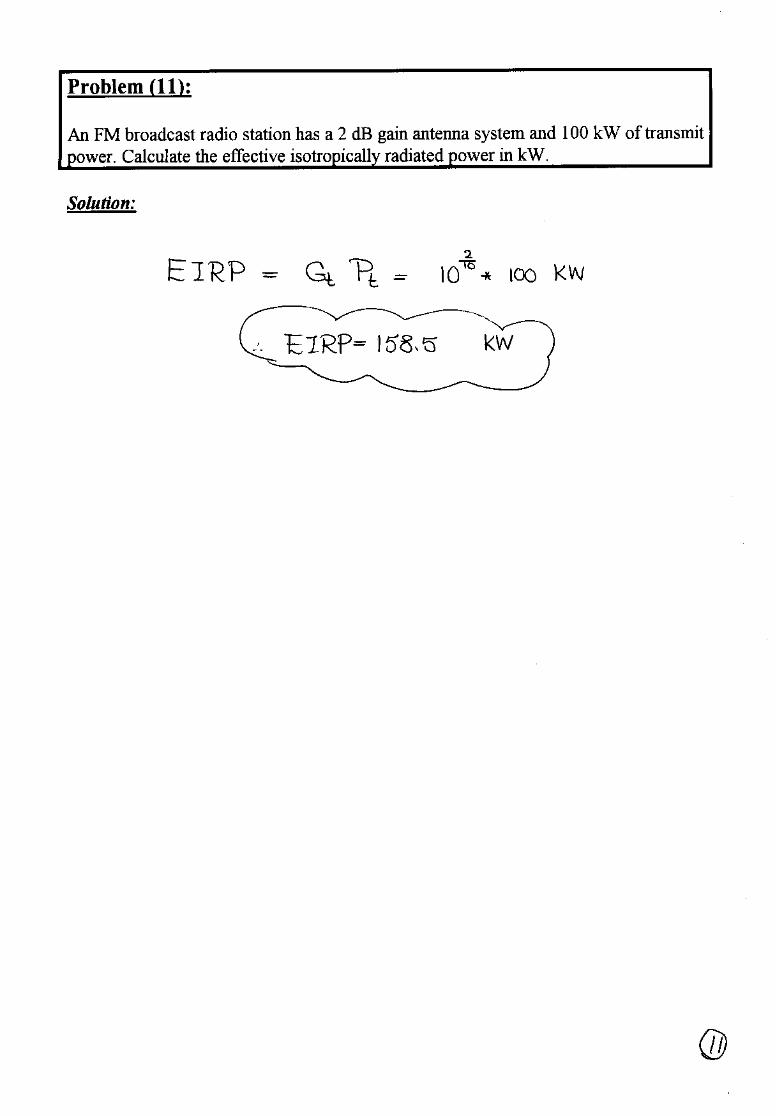
11. An FM broadcast radio station has a 2 dB gain antenna system and 100 kW oftransmit power. Calculate the effective isotropically radiated power in kW
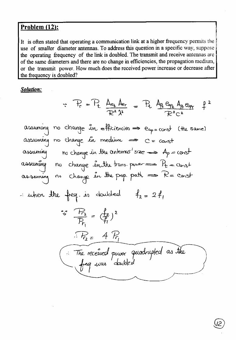
12. It is often stated that operating a communication link at a higher frequency permitsthe use of smaller diameter antennas. To address this question in a specific way,suppose the operating frequency of the link is doubled. The transmit and receiveantennas are of the same diameters and there are no change in efficiencies, thepropagation medium, or the transmit power. How much does the received powerincrease or decrease after the frequency is doubled?
Best Wishes,Prof. Nagda El-MinyawyEng. Maged Ghoneima
7 - 1
Ain Shams UniversityFaculty of Engineering
Electronics and Comm. Eng. Dept.
Antennas4th Year
2000/2001 2nd Semester
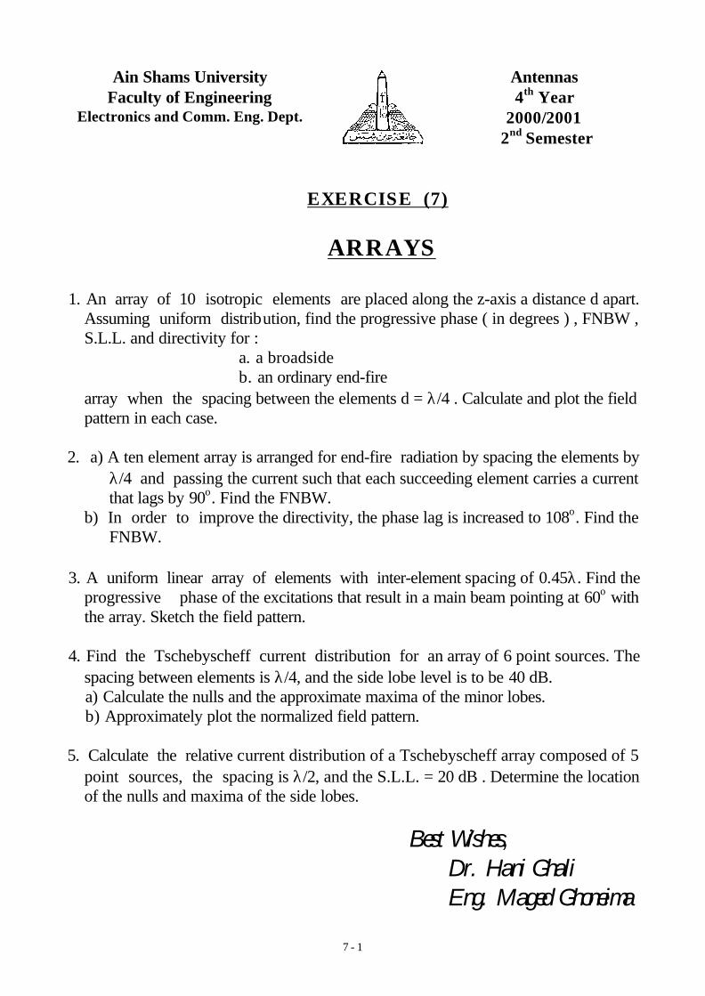
EXERCISE (7)
ARRAYS
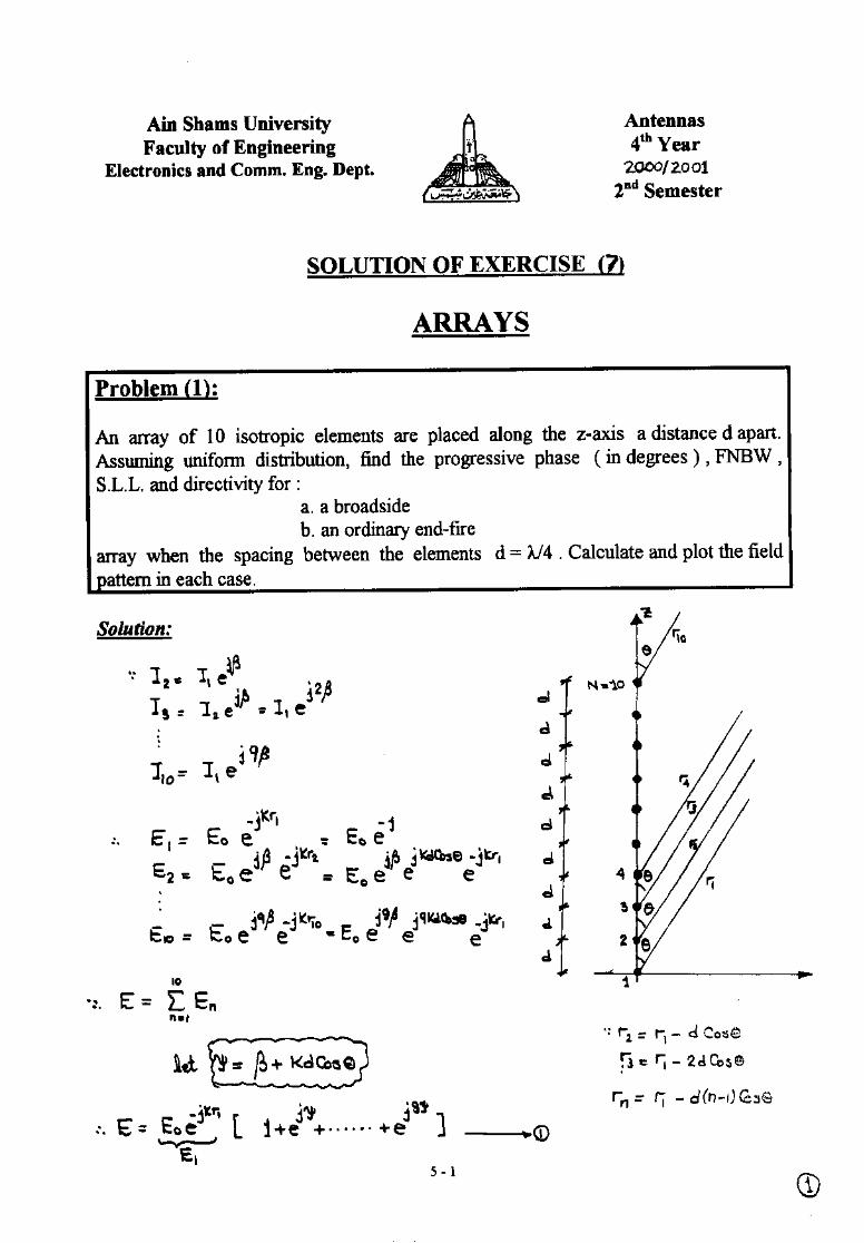
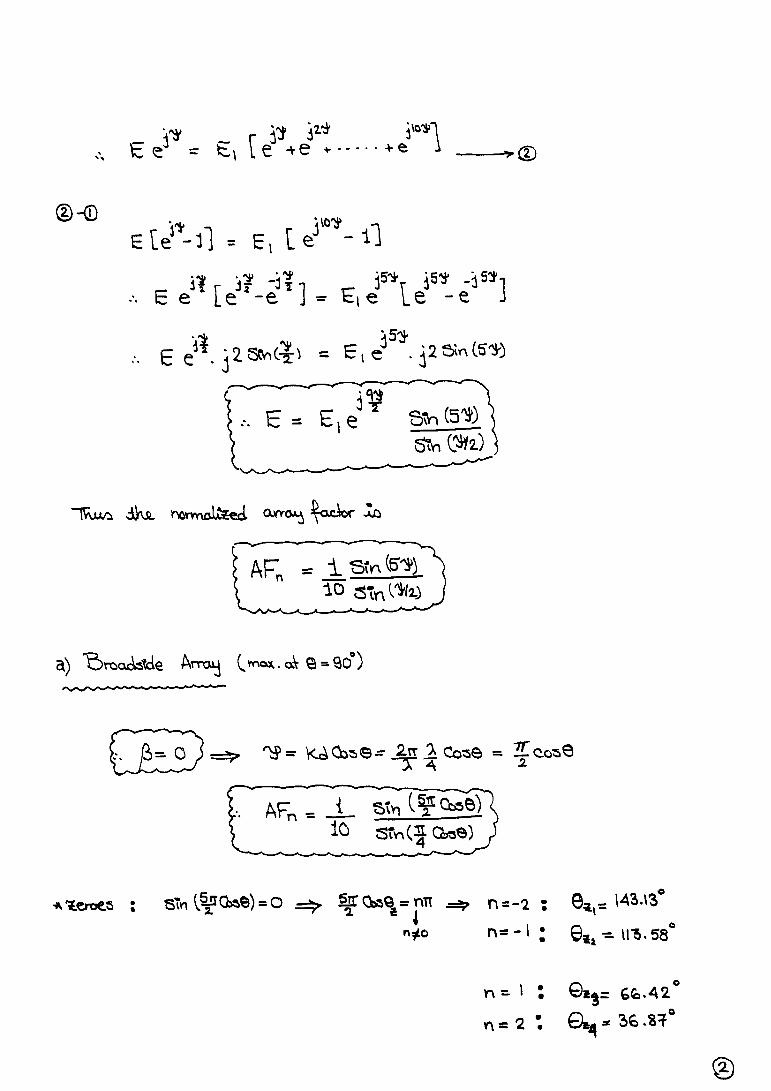
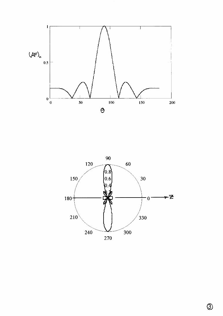
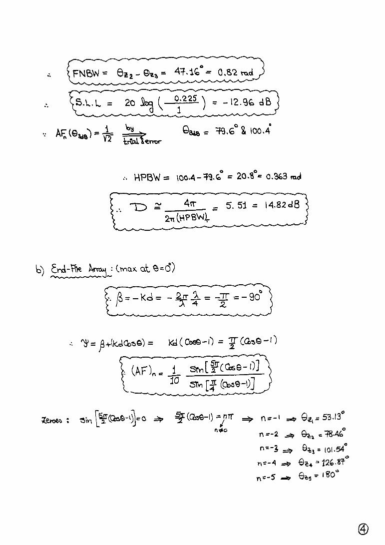
1 . An array of 10 isotropic elements are placed along the z-axis a distance d apart.Assuming uniform distribution, find the progressive phase ( in degrees ) , FNBW ,S.L.L. and directivity for :
a . a broadside b . an ordinary end-fire
array when the spacing between the elements d = λ/4 . Calculate and plot the fieldpattern in each case.
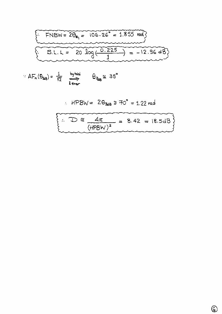
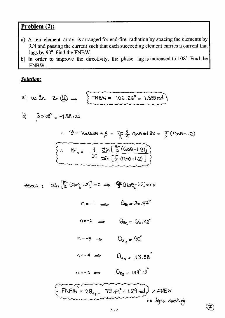
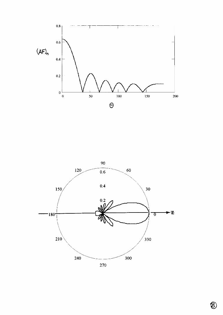
2. a) A ten element array is arranged for end-fire radiation by spacing the elements byλ/4 and passing the current such that each succeeding element carries a currentthat lags by 90o. Find the FNBW.
b) In order to improve the directivity, the phase lag is increased to 108o. Find theFNBW.
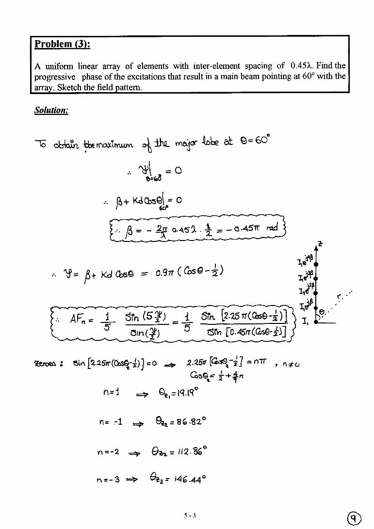
3 . A uniform linear array of elements with inter-element spacing of 0.45λ. Find theprogressive phase of the excitations that result in a main beam pointing at 60o withthe array. Sketch the field pattern.
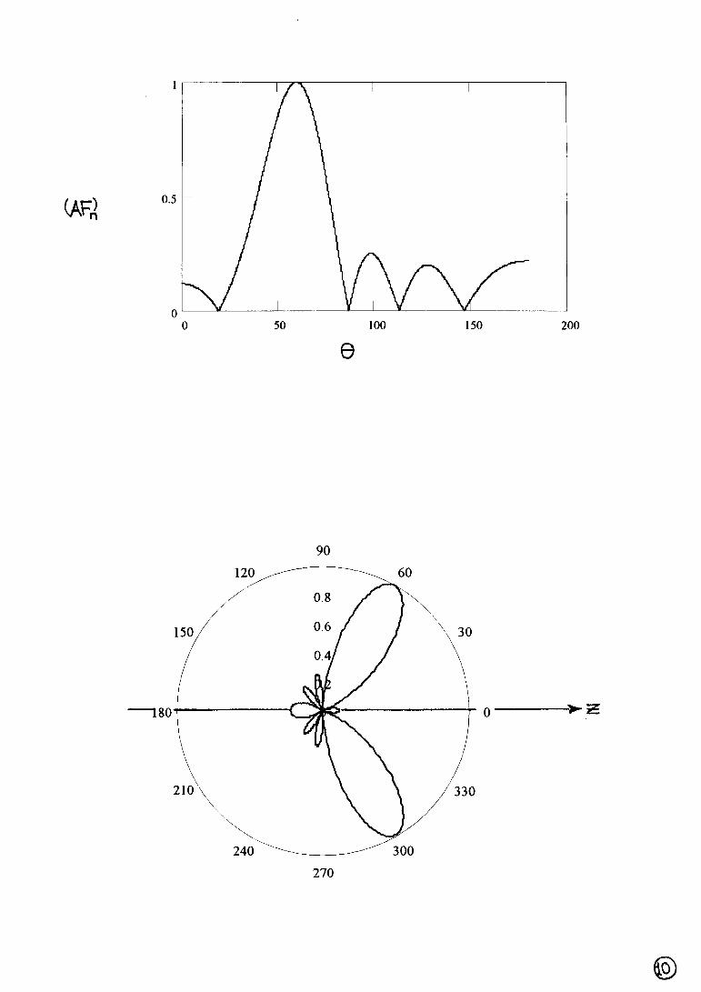
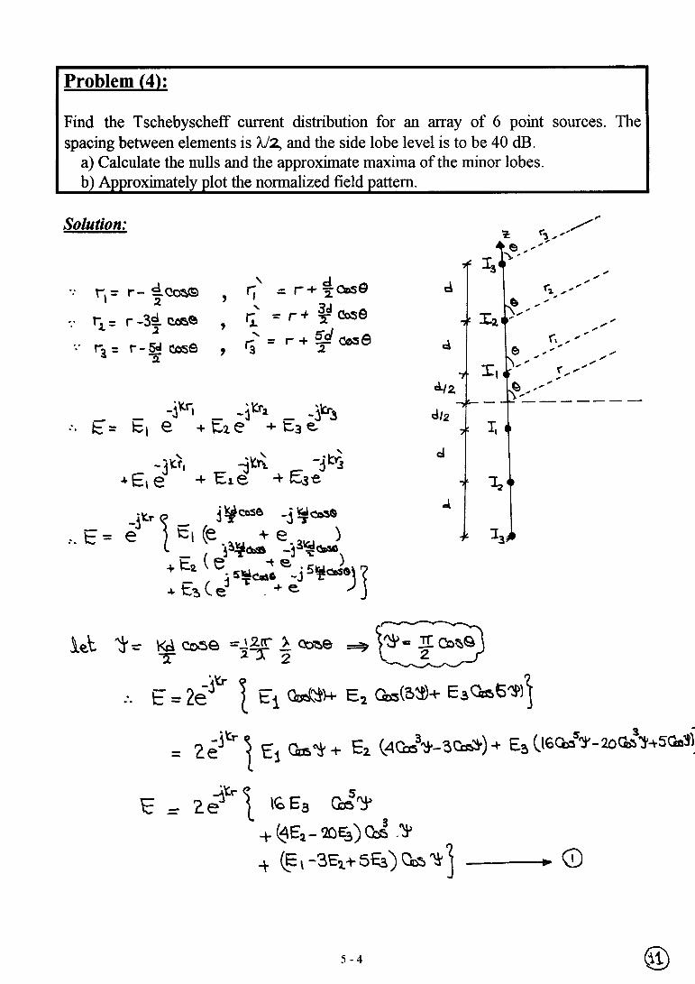
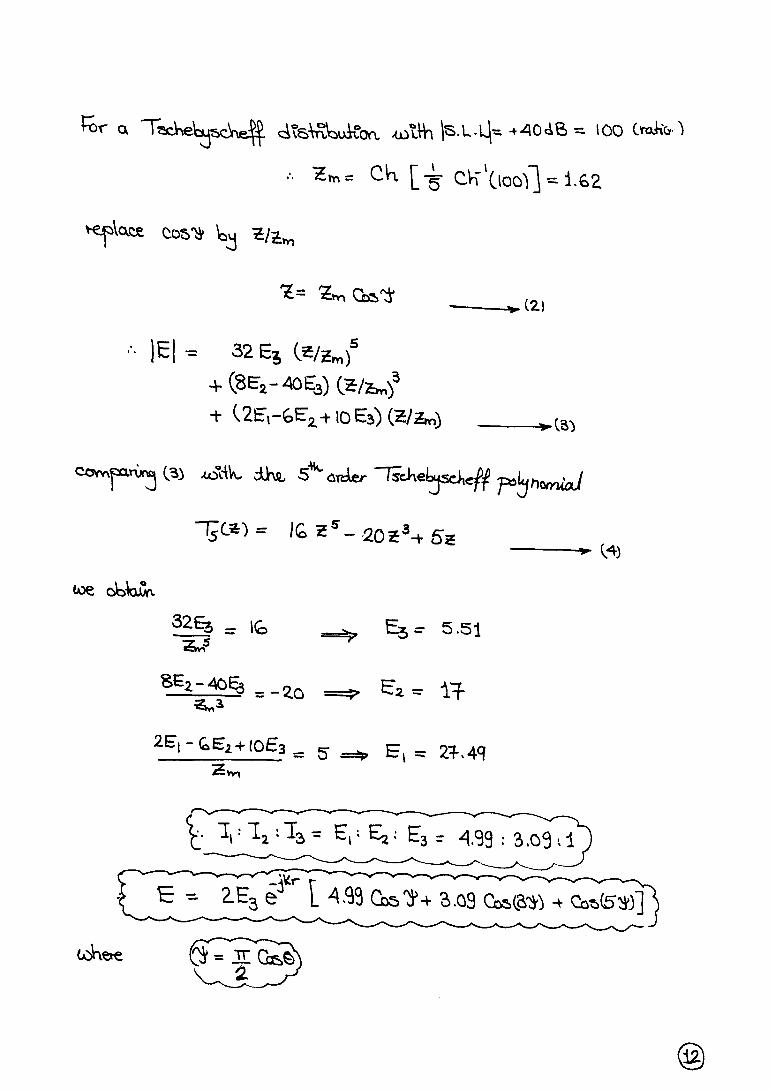
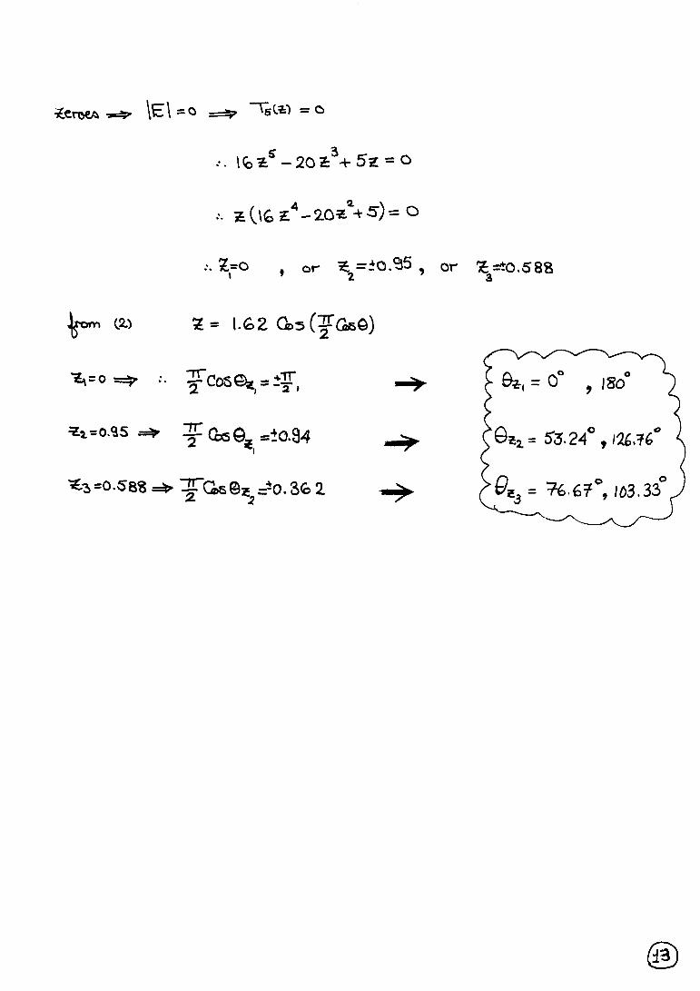
4 . Find the Tschebyscheff current distribution for an array of 6 point sources. Thespacing between elements is λ/4, and the side lobe level is to be 40 dB. a ) Calculate the nulls and the approximate maxima of the minor lobes. b ) Approximately plot the normalized field pattern.
5. Calculate the relative current distribution of a Tschebyscheff array composed of 5point sources, the spacing is λ/2, and the S.L.L. = 20 dB . Determine the locationof the nulls and maxima of the side lobes.
Best Wishes,Dr. Hani GhaliEng. Maged Ghoneima
6 - 1
Ain Shams UniversityFaculty of Engineering
Electronics and Comm. Eng. Dept.
Antennas4th Year
2000/2001 2nd Semester
EXERCISE (8)
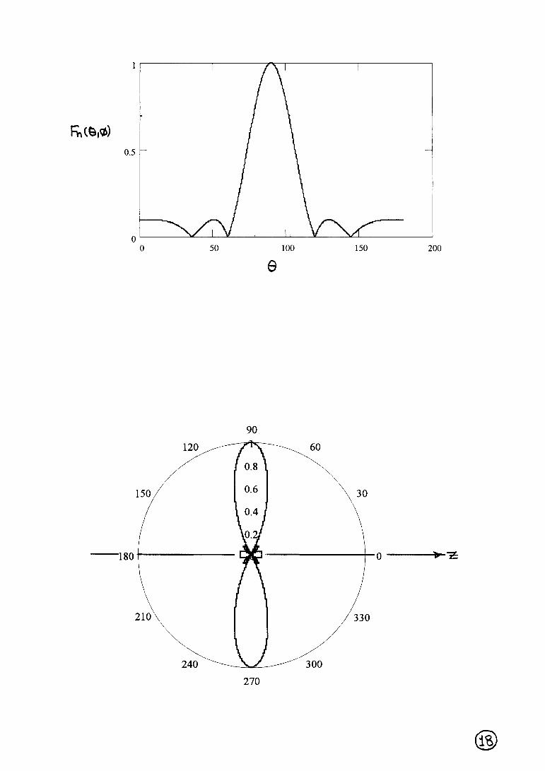
1. It is desired to place the first maximum of a long wire travelling wave antenna at anangle 25° from the axis of the wire. For the wire antenna, find the:
a) exact required length.b) radiation resistance.c) directivity (in dB).
The wire is radiating into free space.
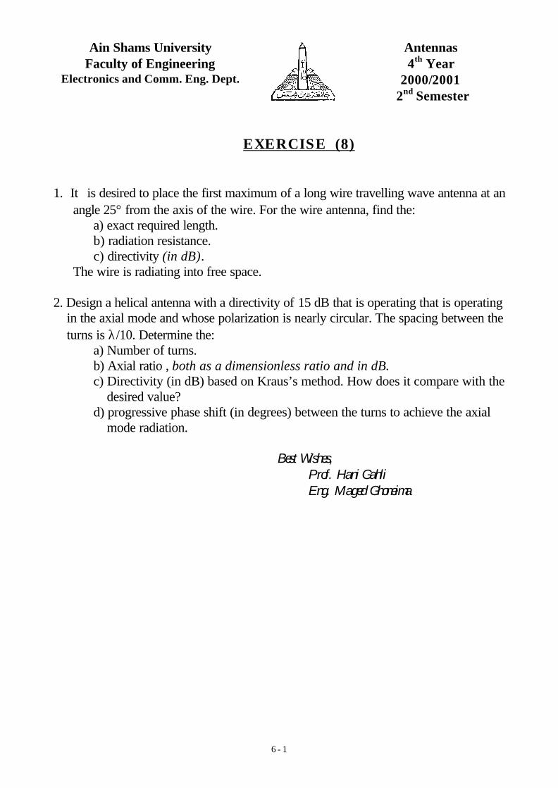
2. Design a helical antenna with a directivity of 15 dB that is operating that is operatingin the axial mode and whose polarization is nearly circular. The spacing between theturns is λ/10. Determine the:
a) Number of turns.b) Axial ratio , both as a dimensionless ratio and in dB.c) Directivity (in dB) based on Kraus’s method. How does it compare with the
desired value?d) progressive phase shift (in degrees) between the turns to achieve the axial
mode radiation.
Best Wishes,Prof. Hani GahliEng. Maged Ghoneima
Ain Shams UniversityFaculty of Engineering
Electronics and Comm. Eng. Dept.
Antennas4th Year
2000/2001 2nd Semester
SOLUTION OF EXERCISE (8)
Problem (1):
It is desired to place the first maximum of a long wire travelling wave antenna at anangle 25° from the axis of the wire. For the wire antenna, find the:
a) exact required length.b) radiation resistance.c) directivity (in dB).
The wire is radiating into free space.
Solution:
a) as F(θ) = cot (θ/2). sin ( kL.sin2(θ/2))As the variations in the sine function of F(θ) are more rapid than those of thecotangent function, the peaks of the lobes occur approximately when
sin ( kL.sin2(θmax/2)) = ± 1kL.sin2(θmax/2) = (2m + 1) π/2 , m = 0, 1, 2, …
As it is required that θmax = 25° then2π (L/λ) . (0.0468) = (2m + 1) π/2 , m = 0, 1, 2, …
∴ L/λ = 5.34 (2m + 1), m = 0, 1, 2, …
Thus the shortest length to satisfy that θθmax = 25°° is L/λλ = 5.34
b) Ω=
λπ
λπ
+λπ
−λ
+π
= 226])
L4(
)L4
sin()
L4(C)
L2ln(415.1[
2
ZR i
intr
c) dB7.1174.14
])
L4(
)L4
sin()
L4(C)
L2ln(415.1[
)]L
371.01(cos
2
1[cot2
D
i
12
==
λπ
λπ
+λπ
−λ
+
λ−=
−
Problem (2):
Design a helical antenna with a directivity of 15 dB that is operating that is operating inthe axial mode and whose polarization is nearly circular. The spacing between theturns is λ/10. Determine the:
a) Number of turns.b) Axial ratio , both as a dimensionless ratio and in dB.c) Directivity (in dB) based on Kraus’s method. How does it compare with the
desired value?d) progressive phase shift (in degrees) between the turns to achieve the axial
mode radiation.
Solution:
a) let C/λ = 1 and as S = λ/10 & D = 31.63, then fromD ≈ 15 N C2 S / λ3
∴∴N = D λλ3 / 15 C2 S ≈≈ 21
b) AR ≈≈ 1 + (1/2N) ≈≈ 1.02
d) as Ψmax = k S cosθmax - φ = ±2mπ
and as axial radiation is required, then θmax = 0, π, and hence the required progressivephase shift (φin degrees) between the turns is given by
φφ = ±±2mππ ±± k S = ±± ππ/5 rad = ±± 36°°
c) as the field pattern is approx
)2
sin(
)2
Nsin(AF
Ψ
Ψ
=
)cos()
2sin(
)2
Nsin()(F θ
Ψ
Ψ
=θ
then by trial & error we can find that the HPBW for the axial radiation case of part (d)is approx. 1.1 radians, then the directivity using Kraus's method
D = 4ππ /(HPBW)2 = 10.38 = 10.16 dB
This gives 4.4 dB error in the directivity used in part (a). This was expected becausethe directivity equation used in part (a) is not valid for the axial radiation case of (d).
6.6667
13.3333
20
30
210
60
240
90
270
120
300
150
330
180 0
Ain Shams UniversityFaculty of Engineering
Electronics and Comm. Eng. Dept.
Antennas4th Year
2000/2001 2nd Semester
Solution of Control Test (2)
a) Design a Dolph - Tschebyscheff array composed of 5 isotropic elements with 20dB S.L.L. such that the main beam is pointing 30o from the array’s broadsidedirection.
b) Sketch the field pattern when the element spacing (d) is i ) d = λ/4. ii ) d = λ.
Note that :T0(z) = 1T1(z) = zTn(z) = 2z Tn-1(z) - Tn-2(z)
])1RR()1RR[(2
1z P/12
00P/12
000 −−+−+=
Solution
If the feeding current to an isotropicelement is I, then its far field radiation canbe expressed by
r
eCIE
jkr−
=
where C is a constant. It can also be seenthat
r1 = r - d cos(θ)r2 = r - 2d cos(θ)r1' = r + d cos(θ)
r2' = r + 2d cos(θ)
We will also assume a progressive phaseβ for the current feeding the arrayelements. This is necessary to adjust themax. of the major lobe to be in a directionother than the broadside direction as
r2'
r1'
θ
θ
θ
θ
θ
r2
r1
r
I2 e- j 2 β
I1 e- j β
I2 ej 2 β
I1 ej β
I0
z
d
d
d
d
required in the problem.The total electric field of the array is thus
'2
jkr2j
2'1
jkrj
1
jkr
0
1
jkrj
1
2
jkr2j
2r
eeCI
r
eeCI
r
eCI
r
eeCI
r
eeCIE
'2
'112 −
β−−
β−−−
β−
β ++++=
)]ee(I)ee(II[r
eCE )coskd(2j)coskd(2j
2)coskd(j)coskd(j
10
jkrθ+β−θ+βθ+β−θ+β
−
++++=
let 2ψ = β + kd cos(θ), then
)]ee(I)ee(II[r
eCE 4j4j
22j2j
10
jkrψ−ψψ−ψ
−
++++=
)]4cos(I2)2cos(I2I[r
eCE 210
jkr
Ψ+Ψ+=−
)]1cos8cos8(I2)1cos2(I2I[r
eCE 24
22
10
jkr
+Ψ−Ψ+−Ψ+=−
)]I2I2I(cos)I4I16(cos)I16[(r
eCE 210
212
42
jkr
+−+Ψ+−+Ψ=−
letz = zm cos(ψ)
whereR0 = S.L.L (ratio) = 10S.L.L(dB)/20
= 10and
zm = Cosh((1/4). Cosh-1(R0)) = 1.293
Hence
)]I2I2I(z)z
I4I16(z)
z
I16[(
r
eCE 210
2
2m
124
4m
2jkr
+−++−
+=−
Comparing the coefficients of the powers of z in this equation with those in the fourthorder Tschebscheff polynomial
T4(z) = 8z4 - 8z2 + 1we find that
8z
I164m
2 =∴I2 = 1.398
8z
I4I162m
12 −=+− ∴I1 = 2.246
1I2I2I 210 =+− ∴I0 = 2.7
∴Io : I1 : I2 = 1: 0.832 : 0.518
Also as it is desired that major lobe maximum be directed 30o from the broadsidedirection, i.e. 60o from the z -axis, then θmax = 60o or 120o
As ψmax = 0, then
kd cos θmax + β = 0
∴ β = ± 0.5 kd
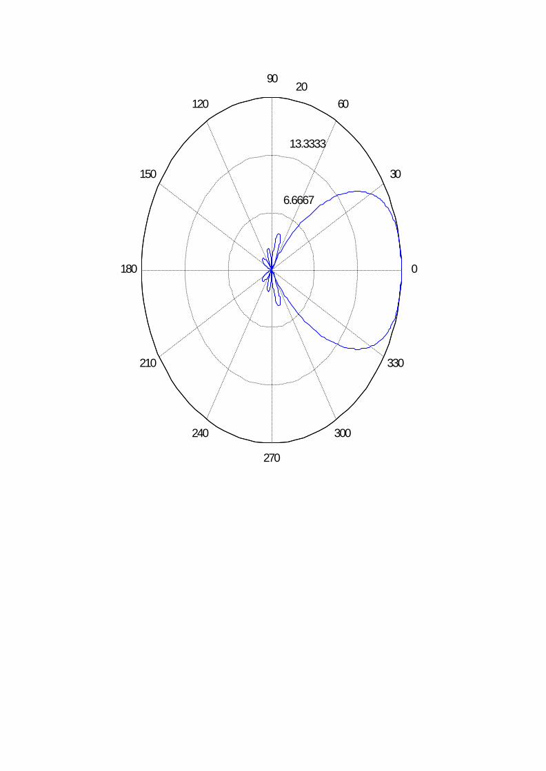
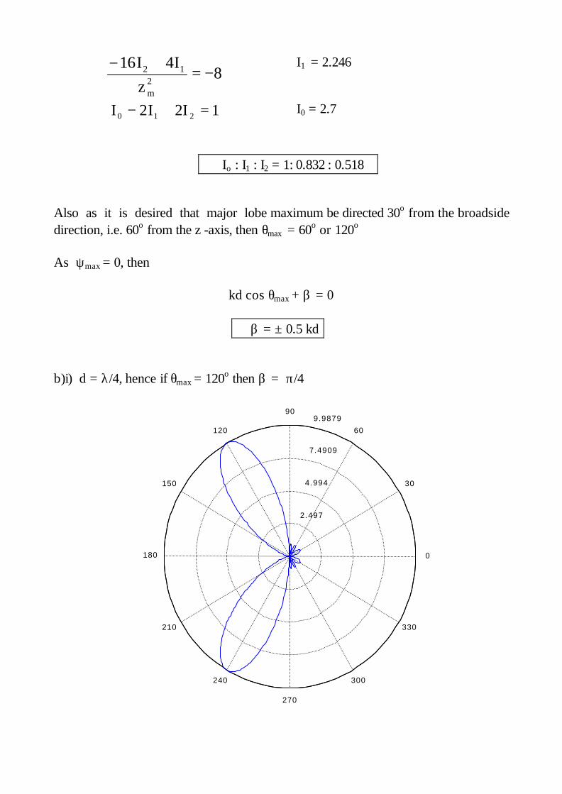
b)i) d = λ/4, hence if θmax = 120o then β = π/4
2.497
4.994
7.4909
9.9879
30
210
60
240
90
270
120
300
150
330
180 0
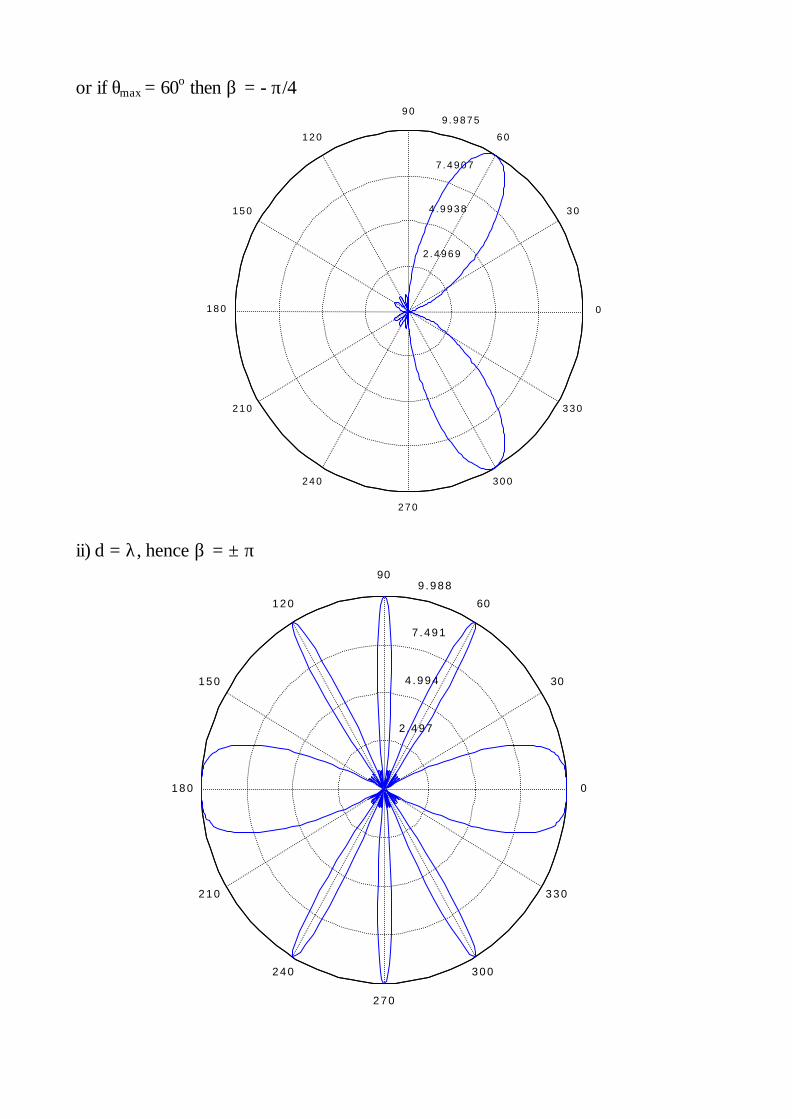
or if θmax = 60o then β = - π/4
2 . 4 9 6 9
4 . 9 9 3 8
7 . 4 9 0 7
9 . 9 8 7 5
3 0
2 1 0
6 0
2 4 0
9 0
2 7 0
1 2 0
3 0 0
1 5 0
3 3 0
1 8 0 0
ii) d = λ, hence β = ± π
2 . 497
4 .994
7 .491
9 .988
30
2 1 0
60
2 4 0
90
2 7 0
1 2 0
3 0 0
1 5 0
3 3 0
1 8 0 0