Embed Size (px)
Citation preview
N A S A
-r . c
z c 4 v) 4 I
TECHNICAL NOTE
APOLLO EXPERIENCE REPORT - LUNAR MODULE LANDING GEAR SUBSYSTEM
by William F. Rogers
M a n n e d Spacecra , Center Hoaston, Texas 77058
N A T I O N A L AERONAUTICS A N D SPACE A D M I N I S T R A T I O N WASHINGTON, D. C. JUNE 1972
https://ntrs.nasa.gov/search.jsp?R=19720018253 2018-08-26T05:53:48+00:00Z
TECH LIBRARY KAFB, NM
21. NO. of Pages
58
0133b50
22. Price'
$3.00
2. Government Accession NO. I - __
1. Rewrt No. 1- NASA m D-6850 4. Title and Subtitle
APOLLO EXPERIENCE REPORT LUNAR MODULE LANDING GEAR SUBSYSTEM
7. Author(s)
William F. Rogers , MSC
9. Performing Organization Name and Address
Manned Spacecraf t Center Houston, Texas 77058
I 12. Sponsoring Agency Name and Address
~~
3. Recipient's Catalog No.
5. Report Date June 1972
6. Performing Organization Code
8. Performing Organization Report No.
MSC S-316 IO. W i r k U n i t NO.
9 14 -1 3 -20 -1 3 -72 11. Contract or Grant No.
13. Type of Report and Period Covered
Technical Note
14. Sponsoring Agency Code National Aeronaut ics and Space Adminis t ra t ion Washington, D.C. 20546
. Supplementary Notes The MSC Di rec to r waived the use of t he International System of Units (SI) for
th i s Apollo Experience Report , because, in h i s judgment, u s e of SI Units would impa i r the usefulness of the r epor t o r r e su l t in excessive cost.
. . 1.;;. Abstract
The development of the lunar module landing gea r subsystem through the Apollo 11 lunar-landing miss ion is presented. to sat isfy the s t ruc tu ra l , mechanical , and landing-performance cons t ra in ts of the vehicle. tensive ana lyses and t e s t s w e r e undertaken to ver i fy the design adequacy. landing -performance ana lys i s s e rved as a p r imary tool in developing the subsys tem hardware and in determining the adequacy of the landing g e a r fo r toppling stabil i ty and energy absorption. The successfu l Apollo 11 lunar-landing mission provided the first opportunity for a complete flight t e s t of the landing g e a r under both na tura l and induced environments.
The landing-gear design evolved f r o m the design requi rements , which had Ex-
Techniques of the
Landing Gear ' Spacecraf t Mechanisms * Lunar Module ' Landing Dynamics ' Landing P e r f o r m a n c e ' Landing-Gear Test ing
' Lunar Landing
- - 19. Security Classif. (of this report) 1 20; Security Classif. (of this page)
None None .. -
For sale by tho National Technical Informat ion Service, Sprinpfield, Virginia 22151
-11 1111 l1ll11l1l1ll11l1ll11ll11111 I I1 I

CONTENTS
Section
SUMMARY . . . . . . . . . . . . . . . . . . . . . . . . . . . . . . . . . . . . . INTRODUCTION . . . . . . . . . . . . . . . . . . . . . . . . . . . . . . . . . . DESIGN REQUIREMENTS AND CRITERLA . . . . . . . . . . . . . . . . . . . . DEVELOPMENT HISTORY . . . . . . . . . . . . . . . . . . . . . . . . . . . . CONFIGURATION DE SCRIP TION . . . . . . . . . . . . . . . . . . . . . . . . . MAJOR PROBLEMS . . . . . . . . . . . . . . . . . . . . . . . . . . . . . . . .
Redesign of the 167-Inch-Tread-Radius Landing Gear . . . . . . . . . . . . Statistical Landing Performance . . . . . . . . . . . . . . . . . . . . . . . Thermal Insulation . . . . . . . . . . . . . . . . . . . . . . . . . . . . . . . Weight Summary . . . . . . . . . . . . . . . . . . . . . . . . . . . . . . . . Failure History . . . . . . . . . . . . . . . . . . . . . . . . . . . . . . . .
APOLLO 11 FLIGHT-TEST RESULTS . . . . . . . . . . . . . . . . . . . . . . CONCLUDING REMARKS . . . . . . . . . . . . . . . . . . . . . . . . . . . . . REFERENCES . . . . . . . . . . . . . . . . . . . . . . . . . . . . . . . . . . . APPENDIX A -LANDING PERFORMANCE OF THE LM . . . . . . . . . . . . APPENDIX B . HARDWARE DEVELOPMENT AND CERTIFICATION
TESTING . . . . . . . . . . . . . . . . . . . . . . . . . . . APPENDIX C -DETAILED CONFIGURATION DESCRIPTION . . . . . . . . .
Page
1
1
2
4
6
9
9
10
12
13
14
16
20
21
22
33
46
iii
TABLES
Table Page
I SIGNIFICANT LANDING-GEAR DESIGN CONCEPTS . . . . . . . . . . . 5
II LANDING-GEAR THERMAL-INSULATION WEIGHT HISTORY . . . . . 12
111 APOLLO 11 LANDING-GEAR-COMPONENT WEIGHT SUMMARY . . . . 14
N LANDING-GEAR FAILURE HISTORY . . . . . . . . . . . . . . . . . . . 15
V APOLLO 11 (LM-5) STRUT-STROKE ESTIMATES. . . . . . . . . . . . 19
A-I LANDING-PERFORMANCE HISTORY O F THE LM . . . . . . . . . . . 31
B-I LANDING-GEARCEPLOYMENT-TESTSUMMARY . . . . . . . . . . . 35
B-II LANDING-GEARDROP-TESTSUMMARY . . . . . . . . . . . . . . . . 36
B-III CERTIFICATION SUMMARY O F THE LM LANDING-GEAR SUBSYSTEM . . . . . . . . . . . . . . . . . . . . . . . . . . . . . . 41
B-IV COMPARISON OF CERTIFIED AND FLIGHT-CONFIGURATION HARDWARE . . . . . . . . . . . . . . . . . . . . . . . . . . . . . . 42
iv
..._.............-.. ..11.-.11- .... I,.,
FIGURES
Figure
1 The LM configuration (contractor technical proposal). . . . . . . . . . 2 Stowed and deployed positions of the landing gear . . . . . . . . . . . . 3 The LM supported in the SLA . . . . . . . . . . . . . . . . . . . . . . 4 The LM landing g e a r . . . . . . . . . . . . . . . . . . . . . . . . . . . 5 Overall view of the LM with the landing gear deployed . . . . . . . . . 6 Landing-gear primary s t rut . . . . . . . . . . . . . . . . . . . . . .
compression stroke . . . . . . . . . . . . . . . . . . . . . . . . . . 7 Primary-strut compression load as a function of
8 Landing-gear secondary strut . . . . . . . . . . . . . . . . . . . . . . 9 Secondary -strut compression and tension loads
Page
3
5
7
7
8
8
8
8
9 9
(a) Compression load as a function of compression stroke . . . . . . (b) Tension load as a function of tension stroke . . . . . . . . . . . .
10 Final-landing-gear landing performance . . . . . . . . . . . . . . . . 10
11 Critical landing conditions . . . . . . . . . . . . . . . . . . . . . . . . 10
12 Apollo 11 attitude and motion touchdown conditions . . . . . . . . . . . 11
13 The LM weight history
(a) The LM touchdown weight history . . . . . . . . . . . . . . . . . . 13 (b) The LM landing-gear weight history . . . . . . . . . . . . . . . . 14
14 Apollo 11 LM (LM-5) on the lunar surface . . . . . . . . . . . . . . . 16
15 Apollo 11 LM (LM-5) minus-Z (aft) footpad . . . . . . . . . . . . . . 16
16 Apollo 11 (LM-5) attitudes and attitude rates at touchdown
17 (a) Pitch angle as a function of time . . . . . . . . . . . . . . . . . . 17 (b) Roll angle as a function of time . . . . . . . . . . . . . . . . . . . . . . . . . . . . . . . . . . . . . . 17 (c) Yaw angle as a function of time . . . . . . . . . . . . . . . . . . . 17 (d) Pitch rate as a function of time
(e) Roll rate as a function of time . . . . . . . . . . . . . . . . . . . 18 (f) Yaw rate as a function of time . . . . . . . . . . . . . . . . . . . . 18
I
V
Figure
17
A -1
A -2
A- 3
A-4
A -5
A -6
A -7
B -1
B -2
B -3
B -4
c -1
c -2
c -3
c -4
c -5
C -6
Apollo 11 (LM-5) descent-engine skir t . . . . . . . . . . . . . . . . . . Validation of touchdown-analysis mathematical model . . . . . . . . . Lunar -surface description
(a) Slope profile . . . . . . . . . . . . . . . . . . . . . . . . . . . . . (b) Protuberance profile . . . . . . . . . . . . . . . . . . . . . . . . . One-sixth-scale drop-test model . . . . . . . . . . . . . . . . . . . . . One-sixth-scale model and drop-test equipment at the prime
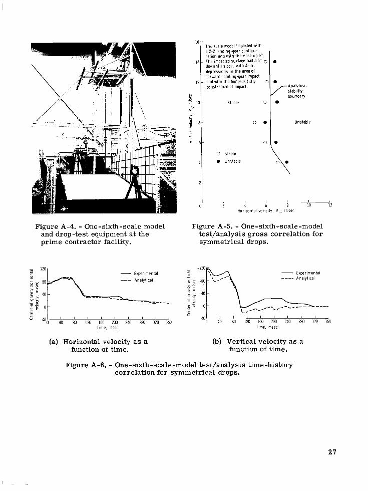
contractor facility . . . . . . . . . . . . . . . . . . . . . . . . . . .
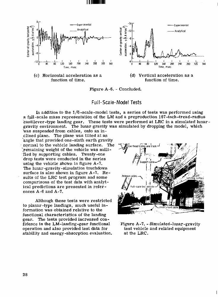
symmetrical drops . . . . . . . . . . . . . . . . . . . . . . . . . . . One-sixth-scale -model test/analysis gross correlation for
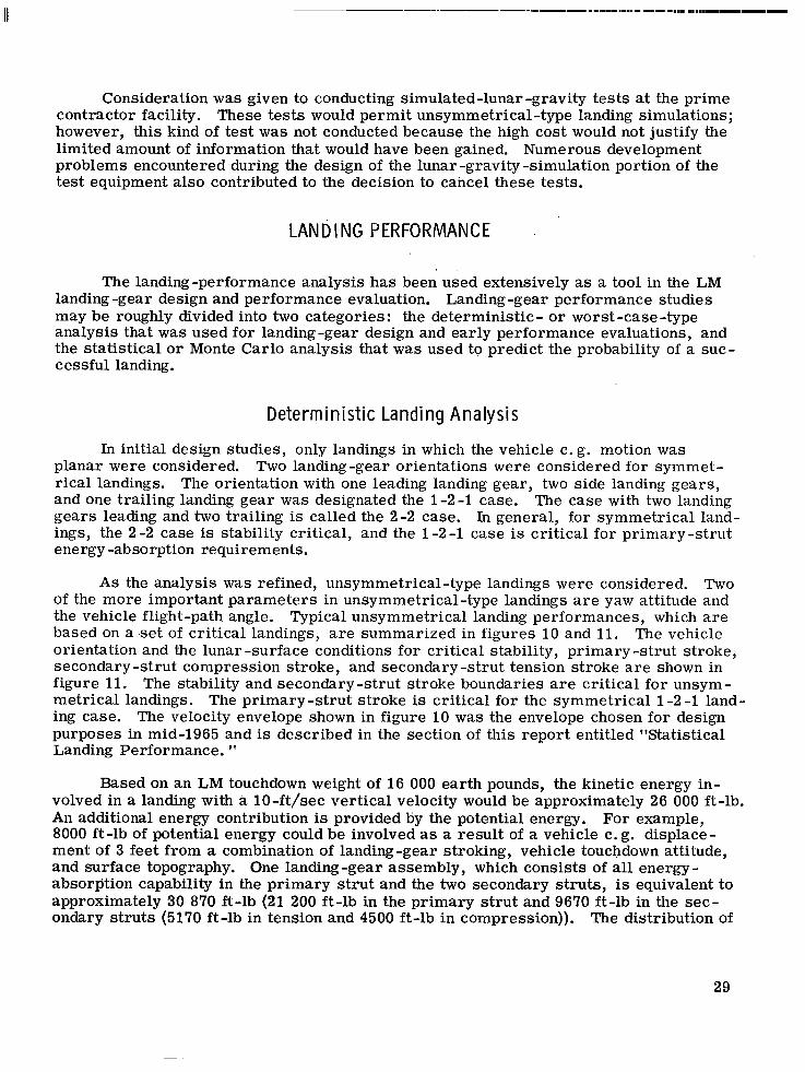
One -sixth -scale -model test/analysis time -history correlation for symmetrical drops
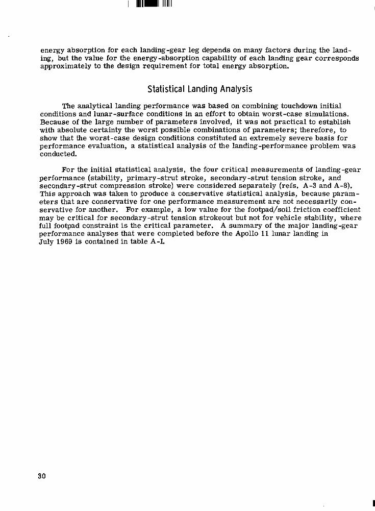
(a) Horizontal velocity as afunction of time . . . . . . . . . . . . . . . (b) Vertical velocity as a function of time . . . . . . . . . . . . . . . (c) Horizontal acceleration as a function of time . . . . . . . . . . . . (d) Vertical acceleration as a function of time . . . . . . . . . . . . . Simulated-lunar -gravity test vehicle and related equipment
at the LRC . . . . . . . . . . . . . . . . . . . . . . . . . . . . . . . Test summary of the LM landing gear . . . . . . . . . . . . . . . . . . Landing-gear drop-test equipment . . . . . . . . . . . . . . . . . . . . Landing gear configured for unsymmetrical drop test . . . . . . . . . . Landing gear following drop into simulated lunar soil . . . . . . . . . . Landing-gear uplock mechanism . . . . . . . . . . . . . . . . . . . . . Landing-gear deployment and downlock mechanism
(a) Stowed position . . . . . . . . . . . . . . . . . . . . . . . . . . . . (b) Down and locked position . . . . . . . . . . . . . . . . . . . . . . . Lunar-surface-sensing-probe-deployment mechanism . . . . . . . . . Lunar -surface -sensing-probe switch . . . . . . . . . . . . . . . . . . Landing-gear footpad . . . . . . . . . . . . . . . . . . . . . . . . . . . Landing-gear -assembly test flow . . . . . . . . . . . . . . . . . . . .
vi
Page
20
22
25 25
26
27
27
27 27 28 28
28
33
37
37
37
48
48 48
50
50
51
52
APOLLO EXPERI ENCE REPORT
LUNAR MODULE LANDING GEAR SUBSYSTEM
By Wi l l iam F. Rogers Manned Spacecraft Center
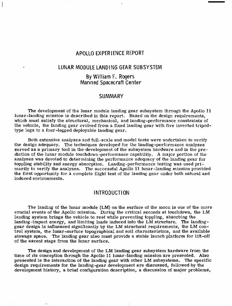
SUMMARY
The development of the lunar module landing gear subsystem through the Apollo 11 lunar-landing mission is described in this report. which must satisfy the structural, mechanical, and landing -performance constraints of the vehicle, the landing gear evolved from a fixed landing gear with five inverted tripod- type legs to a four-legged deployable landing gear.
Based on the design requirements,
Both extensive analyses and full-scale and model tests were undertaken to verify the design adequacy. served as a primary tool in the development of the subsystem hardware and in the pre- diction of the lunar module touchdown-performance capability. A major portion of the analyses was devoted to determining the performance adequacy of the landing gear for toppling stability and energy absorption. Landing-performance testing was used pr i - marily to verify the analyses. The successful Apollo 11 lunar-landing mission provided the first opportunity for a complete flight test of the landing gear under both natural and induced environments.
The techniques developed for the landing -performance analyses
INTRODUCTION
The landing of the lunar module (LM) on the surface of the moon is one of the more crucial events of the Apollo mission. During the critical seconds at touchdown, the LM landing system brings the vehicle to rest while preventing toppling, absorbing the landing-impact energy, and limiting loads induced into the LM structure. The landing- gear design is influenced significantly by the LM structural requirements, the LM con- t rol system, the lunar -surface topographical and soil characteristics, and the available stowage space. The landing gear also must provide a stable launch platform for lift-off of the ascent stage from the lunar surface.
The design and development of the LM landing gear subsystem hardware from the time of 'its conception through the Apollo 11 lunar-landing mission are presented. Also presented is the interaction of the landing gear with other LM subsystems. The specific design requirements for the landing -gear development are discussed, followed by the development history, a brief configuration description, a discussion of major problems,
and a summary of flight test results. Detailed information about the LM landing per- formance, the hardware development and testing, and the landing -gear configuration is given in appendixes A, B, and C, respectively.
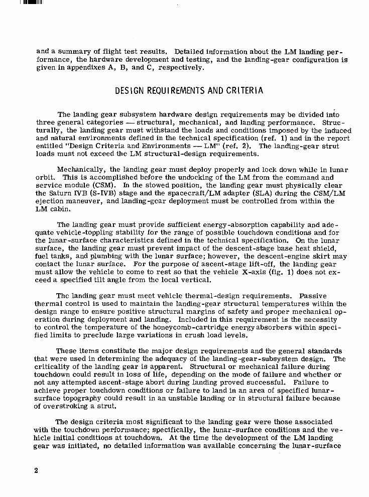
DESIGN REQUIREMENTS AND CRITERIA
The landing gear subsystem hardware design requirements may be divided into three general categories - structural, mechanical, and landing performance. turally, the landing gear must withstand the loads and conditions imposed by the induced and natural environments defined in the technical specification (ref. 1) and in the report entitled "Design Criteria and Environments - LM" (ref. 2). loads must not exceed the LM structural-design requirements.
Struc -
The landing-gear s t rut
Mechanically, the landing gear must deploy properly and lock down while in lunar orbit. service module (CSM). In the stowed position, the landing gear must physically clear the Saturn IVB (S-IVB) stage and the spacecraft/LM adapter (SLA) during the CSM/LM ejection maneuver, and landing-gear deployment must be controlled from within the LM cabin,
This is accomplished before the undocking of the LM from the command and
The landing gear must provide sufficient energy -absorption capability and ade - quate vehicle -toppling stability for the range' of possible touchdown conditions and for the lunar -surface characteristics defined in the technical specification. On the lunar surface, the landing gear must prevent impact of the descent-stage base heat shield, fuel tanks, and plumbing with the lunar surface; however, the descent-engine skir t may contact the lunar surface. For the purpose of ascent-stage lift-off, the landing gear must allow the vehicle to come to rest so that the vehicle X-axis (fig. 1) does not ex- ceed a specified tilt angle from the local vertical.
The landing gear must meet vehicle thermal-design requirements. Passive thermal control is used to maintain the landing-gear structural temperatures within the design range to ensure positive structural margins of safety and proper mechanical op- eration during deployment and landing. Included in this requirement is the necessity to control the temperature of the honeycomb -cartridge energy absorbers within speci - fied limits to preclude large variations in crush load levels.
These items constitute the major design requirements and the general standards that were used in determining the adequacy of the landing-gear-subsystem design. criticality of the landing gear is apparent. Structural or mechanical failure during touchdown could result in loss of life, depending on the mode of failure and whether or not any attempted ascent -stage abort during landing proved successful. Failure to achieve proper touchdown conditions o r failure to land in an area of specified lunar- surface topography could result in an unstable landing o r in structural failure because of overstroking a strut.
The
The design criteria most significant to the landing gear were those associated with the touchdown performance; specifically, the lunar -surface conditions and the ve - hicle initial conditions at touchdown. At the time the development of the LM landing gear was initiated, no detailed information was available concerning the lunar -surface
2
-2 I
I
- X +Z
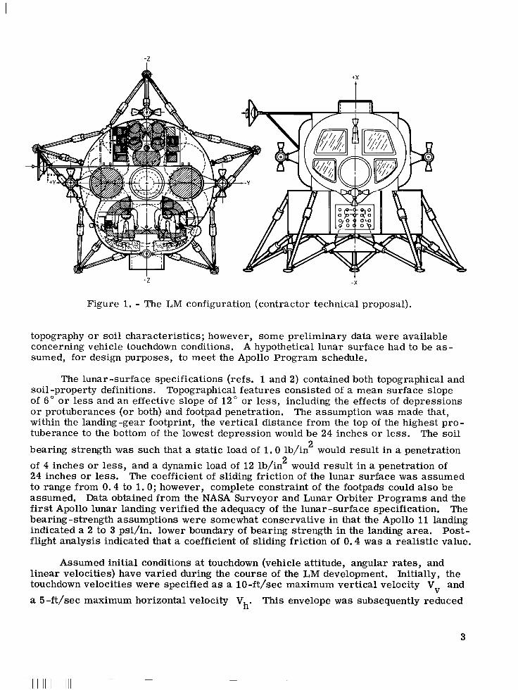
Figure 1. - The LM configuration (contractor technical proposal).
topography o r soil characteristics; however, some preliminary data were available concerning vehicle touchdown conditions. sumed, for design purposes, to meet the Apollo Program schedule.
A hypothetical lunar surface had to be as-
The lunar -surface specifications (refs. 1 and 2) contained both topographical and soil -property definitions. of 6" o r less and an effective slope of 12" o r less, including the effects of depressions o r protuberances (or both) and footpad penetration. within the landing-gear footprint, the vertical distance from the top of the highest pro- tuberance to the bottom of the lowest depression would be 24 inches o r less. The soil
bearing strength was such that a static load of 1 .0 lb/in would result in a penetration of 4 inches o r less, and a dynamic load of 12 lb/in would result in a penetration of 24 inches or less. The coefficient of sliding friction of the lunar surface was assumed to range from 0.4 to 1.0; however, complete constraint of the footpads could also be assumed. Data obtained from the NASA Surveyor and Lunar Orbiter Programs and the first Apollo lunar landing verified the adequacy of the lunar-surface specification. The bearing -strength assumptions were somewhat conservative in that the Apollo 11 landing indicated a 2 to 3 psi/in. lower boundary of bearing strength in the landing area. Post- flight analysis indicated that a coefficient of sliding friction of 0.4 was a realistic value.
Topographical features consisted of a mean surface slope
The assumption was made that,
2
2
Assumed initial conditions at touchdown (vehicle attitude, angular rates, and linear velocities) have varied during the course of the LM development. Initially, the touchdown velocities were specified as a lO-ft/sec maximum vertical velocity V and a 5 -ft/sec maximum horizontal velocity Vh. This envelope was subsequently reduced
V
3
' Ill1 IIIIIIII I 1 I l l I l l 1
to a 4 -ft/sec maximum horizontal velocity, based on updated simulation data. Later, the envelope was further reduced, as is discussed in the section entitled "Redesign of the 167-Inch-Tread-Radius Landing Gear. 'I This final reduction resulted in an en- velope where, for Vv I 7 ft/sec, Vh = 4 ft/sec; and, for 7 ft/sec 5 Vv 5 IO ft/sec,
40 - 5 V ft/sec. Further details of the lunar-surface description and initial con- 3 v Vh = 3 ditions at touchdown are provided in appendix A.
For the purpose of structural design, the ultimate safety factor for the landing The 1.35 safety gear was 1. 35, with an ultimate safety factor of 1.50 on all fittings.
factor was based on the landing gear being a load-limited device; that is, the honeycomb energy absorbers used in the landing gear crush at predictable load levels, thereby ab- solutely limiting the loads that can be induced into the landing gear.
DEVELOPMENT HI STORY
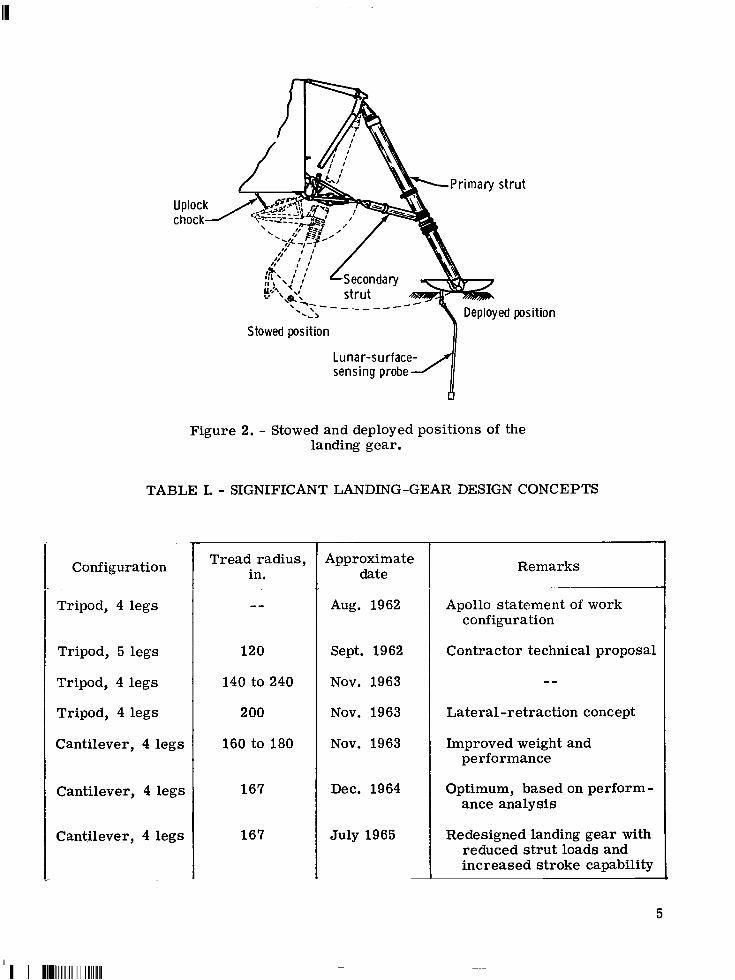
The general design requirements discussed in the previous section have applied to the LM landing system since the decision in 1962 to use the lunar orbit rendezvous technique to accomplish a manned lunar landing. The LM configuration proposed by the contractor (fig. 1) consisted of a five -legged, fixed, inverted-tripod-type landing gear attached to a cylindrical descent stage. The five-legged landing gear was the lightest arrangement and provided the largest diameter base consistent with the space restrictions of the SLA without retraction. Configurations of four and six legs were also considered. the selected arrangement and provided only a small increase in stabili& for the same diameter base. To provide the same stability as was available in the five-legged con- figuration, the four-legged landing gear required a larger diameter and retraction for stowage in the SLA.
The six-legged landing gear was approximately 40 pounds heavier than
Soon after the LM contract was awarded, the basic descent stage was changed from a cylindrical structure to a cruciform-type structure that could accommodate a four -legged landing gear more readily. The inverted-tripod-type landing gear, which consisted of a primary s t rut and two secondary s t ruts joined near the footpad (fig. l), is typical of the early configurations that were considered for both the cylindrical- and cruciform -shaped descent stages.
After selection of the four -legged landing gear, which required retraction for stowage because of the large landing -gear tread radius, many detailed inverted-tripod landing-gear leg designs were studied. Landing-gear tread radii ranged from 140 to 240 inches, with the tread radius defined as the distance from the vehicle longitudinal axis to the center of the landing-gear footpad.
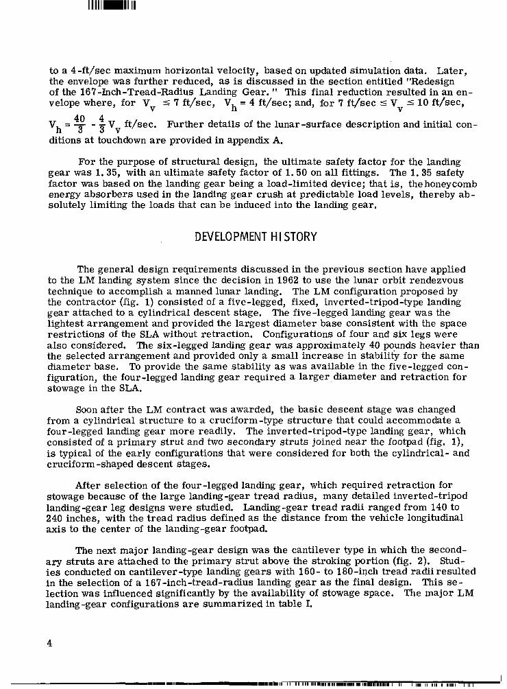
The next major landing-gear design was the cantilever type in which the second- a ry struts are attached to the primary strut above the stroking portion (fig. 2). Stud- ies conducted on cantilever-type landing gears with 160- to 180-inch tread radii resulted in the selection of a 167-inch-tread-radius landing gear as the final design, This se- lection was influenced significantly by the availability of stowage space. The major LM landing -gear configurations are summarized in table I.
4
s t r u t
-- b , Deployed position
I Stowed position
Lunar-su rface- sensing probe
Figure 2. - Stowed and deployed positions of the landing gear.
TABLE I. - SIGNIFICANT LANDING-GEAR DESIGN CONCEPTS
Configuration
Tripod, 4 legs
Tripod, 5 legs
Tripod, 4 legs
Tripod, 4 legs
Cantilever, 4 legs
Cantilever, 4 legs
Cantilever, 4 legs
Tread radius, in.
120
140 to 240
200
160 to 180
167
167
Approximate date
Aug. 1962
Sept. 1962
Nov. 1963
Nov. 1963
Nov. 1963
Dec. 1964
July 1965
Remarks
Apollo statement of work configuration
Contractor technical proposal
--
Lateral-retraction concept
Improved weight and performance
Optimum, based on perform- ance analysis
Redesigned landing gear with reduced s t rut loads and increased stroke capability
5
Design studies conducted on various landing-gear s t rut arrangements show that the cantilever-type landing gear has several advantages over the inverted-tripod arrangement. The cantilever -type landing gear weighs less, primarily because the secondary s t ruts are much shorter than those in the inverted-tripod design. ening of the secondary s t ru ts and the simplification of the primary-strut-to -footpad attachment compensated for the increase in weight of the primary strut that was neces- sitated by the high bending loads encountered in the cantilever-type design. Because of light weight and relatively short length, the cantilever -type -landing-gear secondary struts are primarily axially loaded members that bend as a result of lateral inertial loading only. Another advantage of the cantilever-type design is that the location of the secondary struts minimizes interference problems in the vicinity of the footpad. Land- ing analyses indicated that the cantilever -type landing gear provided greater toppling stability than an inverted-tripod landing gear of the same tread radius, primarily be- cause the cantilever-type landing gear provided a lower, and thus a more favorable, center -of -gravity (c. g. ) location.
The short-
During the course of the landing-gear development, extensive testing was under-
During the development phases, testing was performed taken to investigate specific a reas of concern, such as primary-strut bearings and honeycomb energy absorbers. for all significant ground and flight environments. Certification testing, especially deployment tes ts in a thermal-vacuum environment and drop tes ts at design landing conditions, was accomplished, in accordance with Apollo Program test philosophy, on as complete a subsystem assembly as possible. were used for the majority of the certification program. verification testing was performed at both component and assembly levels. Model tes ts were conducted in support of the landing-performance analysis.
Thus, landing-gear-assembly tes ts Development and design-
Landing dynamics w a s a major concern in the LM development. The LM touchdown -performance characteristics had to be compatible with a broadly defined lunar surface and with the LM control-system characteristics, Furthermore, the LM had to be capable of landing under conditions of zero visibility. Because of the diffi- culty in conducting meaningful and comprehensive full -scale landing -performance tests in the earth -gravity environment, extensive landing -dynamics analyses, using digital - computer simulations, were performed to evaluate the landing gear for both toppling stability and energy -absorption capability, The analyses were conducted concurrently with much of the structural and mechanical testing previously discussed. Results of both the development testing and the performance analyses were used to determine an optimum landing gear based on the design requirements. Analysis of the landing-gear performance also constituted a major portion of the flight certification. The landing performance and the hardware development and certification testing are discussed in detail in appendixes A and B, respectively.
CONFIGURATION DESCRIPTION
A sketch of the LM mounted in the SLA with the landing gear in the stowed posi- tion is shown in figure 3. Apollo spacecraft is in lunar orbit. Deployment occurs during LM systems activation before powered descent to the lunar surface. 167.57 inches from the vehicle X-axis. A landing-gear leg assembly in both the stowed
The landing gear remains in the stowed position until the
The center of each LM footpad is
6
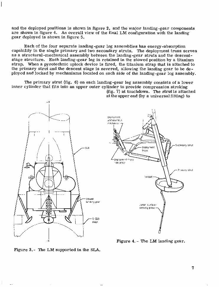
and the deployed positions is shown in figure 2, and the major landing-gear components a r e shown in figure 4. An overall view of the final LM configuration with the landing gear deployed is shown in figure 5.
Each of the four separate landing-gear leg assemblies has energy -absorption capability in the single primary and two secondary struts. The deployment t russ serves as a structural-mechanical assembly between the landing-gear struts and the descent- stage structure. Each landing-gear leg is retained in the stowed position by a titanium strap. When a pyrotechnic uplock device is fired, the titanium strap that is attached to the primary s t rut and the descent stage is severed, allowing the landing gear to be de- ployed and locked by mechanisms located on each side of the landing-gear leg assembly,
The primary s t rut (fig. 6) on each landing-gear leg assembly consists of a lower iMer cylinder that fits into an upper outer cylinder to provide compression stroking
(fig. 7) at touchdown. The strut is attached at the upper end (by a universal fitting) to
t X
-X
Figure 3.- The LM supported in the SLA.
1 1
Deployment and downlock I /
Secondary s t ru t
1 u n a r surface-
Figure 4. - The LM landing gear.
7
I n n e r cyl inder cyl inder io n
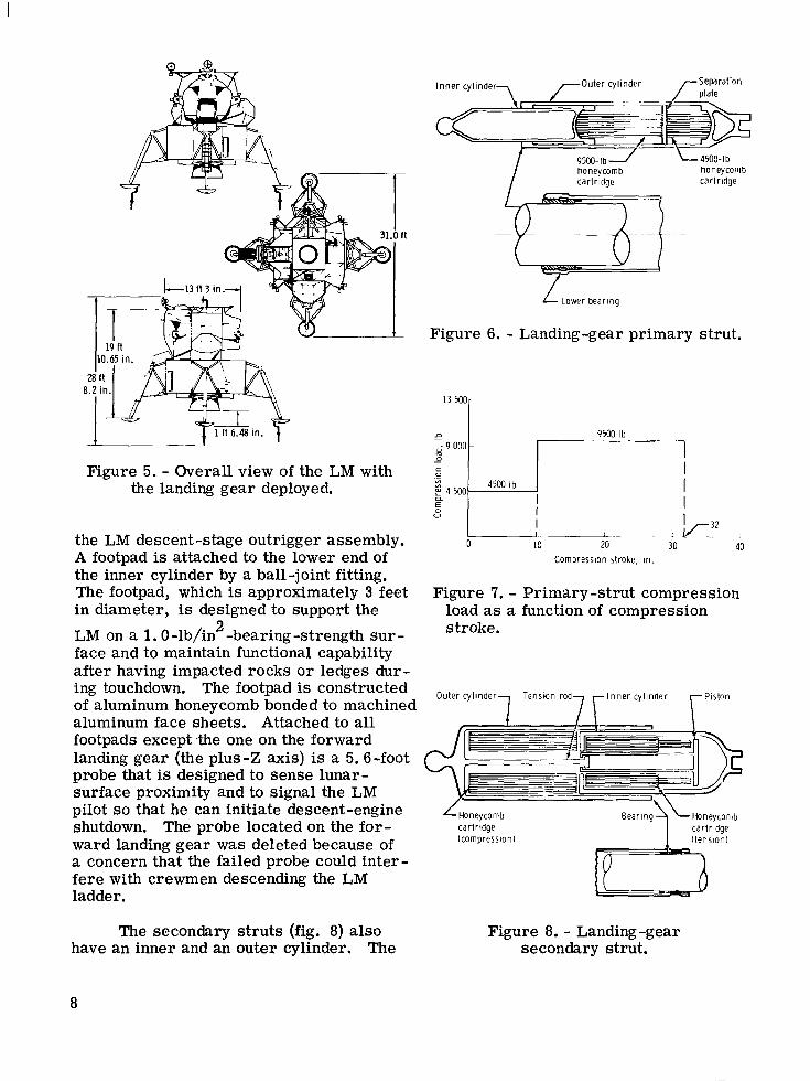
Figure 5. - Overall view of the LM with the landing gear deployed.
the LM descent-stage outrigger assembly. A footpad is attached to the lower end of the inner cylinder by a ball-joint fitting. The footpad, which is approximately 3 feet in diameter, is designed to support the
4500-lb honeycomb
9500- Ib honeycomb carlridge carlridge
L tower bearing
Figure 6. - Landing-gear primary strut.
0 10 20
~-
I I I I I
1 1 c 2 I
30 40 Compression stroke. i n .
Figure 7. - Primary-strut compression load as a function of compression
2 stroke. LM on a 1.0 -lb/in -bearing -strength sur - face and to maintain functional capability after having impacted rocks o r ledges dur- ing ouchd down. The footpad is constructed of aluminum honeycomb bonded to machined aluminum face sheets. Attached to all footpads except the one on the forward landing gear (the plus-Z axis) is a 5.6-foot probe that is designed to sense lunar- surface proximity and to signal the LM pilot so that he can initiate descent-engine
ward landing gear was deleted because of a concern that the failed probe could inter- fere with crewmen descending the LM ladder ,
shutdown. The probe located on the for- cartridge lcompressionl
The secondary s t ruts (fig. 8) also Figure 8. - Landing-gear have an inner and an outer cylinder. The secondary strut.
8
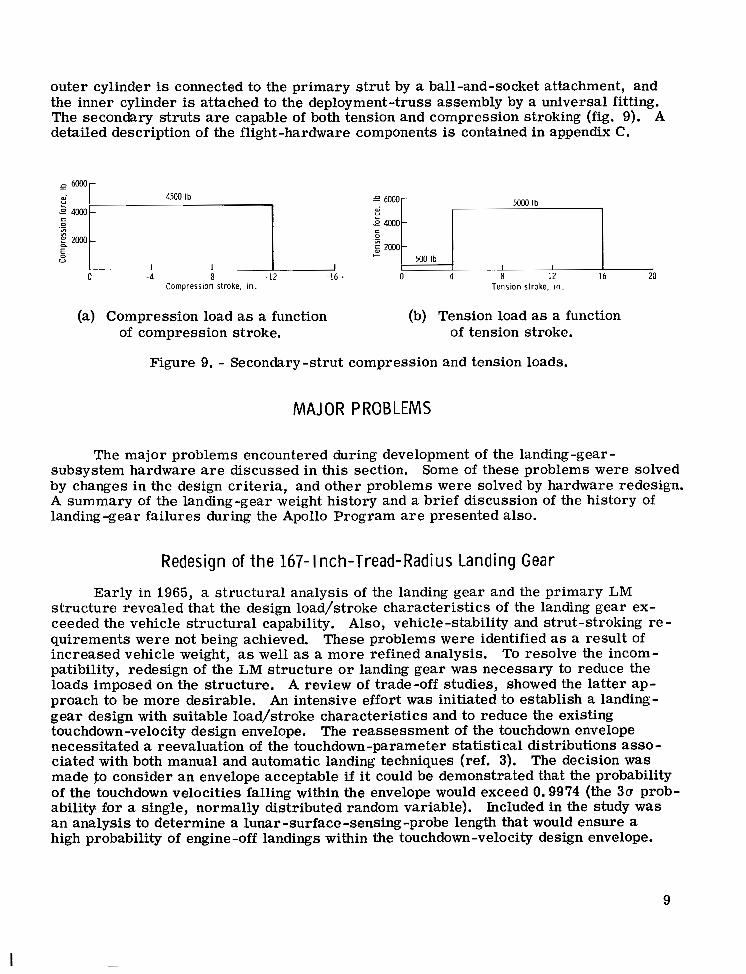
outer cylinder is connected to the primary s t rut by a ball-and-socket attachment, and the inner cylinder is attached to the deployment-truss assembly by a universal fitting. The secondary struts are capable of both tension and compression stroking (fig. 9). A detailed description of the flight-hardware components is contained in appendix C.
: u 6o00r 4500 Ib
.- i m 0 - i E CL zoo0
E V
0 - 4 -8 - 12 Compression stroke. in.
I -16 *
5000 Ib e 6000
500 Ib +
0 4 8 12 16 20
5000 Ib I
500 Ib
0 4
+
8 12 16 20 Tension stroke, in.
(a) Compression load as a function (b) Tension load as a function of compression stroke. of tension stroke.
Figure 9. - Secondary -strut compression and tension loads.
MAJOR PROBLEMS
The major problems encountered during development of the landing-gear - subsystem hardware a r e discussed in this section. Some of these problems were solved by changes in the design criteria, and other problems were solved by hardware redesign. A summary of the landing-gear weight history and a brief discussion of the history of landing -gear failures during the Apollo Program a r e presented also.
Redesign of t h e 167- I nch-Tread-Radius Landing Gear
Early in 1965, a structural analysis of the landing gear and the primary LM structure revealed that the design load/stroke characteristics of the landing gear ex- ceeded the vehicle structural capability. Also, vehicle -stability and strut-stroking r e - quirements were not being achieved. These problems were identified as a result of increased vehicle weight, as well as a more refined analysis. To resolve the incom- patibility, redesign of the LM structure o r landing gear was necessary to reduce the loads imposed on the structure. A review of trade-off studies, showed the latter ap- proach to be more desirable. An intensive effort was initiated to establish a landing- gear design with suitable load/stroke characteristics and to reduce the existing touchdown-velocity design envelope. necessitated a reevaluation of the touchdown-parameter statistical distributions asso - ciated with both manual and automatic landing techniques (ref. 3). made ;to consider an envelope acceptable if it could be demonstrated that the probability of the touchdown velocities falling within the envelope would exceed 0.9974 (the 3a prob- ability, for a single, normally distributed random variable). Included in the study was an analysis to determine a lunar -surface -sensing -probe length that would ensure a high probability of engine -off landings within the touchdown-velocity design envelope.
The reassessment of the touchdown envelope
The decision was
9
I
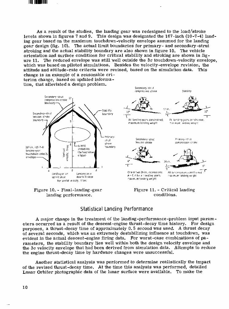
As a result of the studies, the landing gear was redesigned to the loadjstroke levels shown in figures 7 and 9. ing gear based on the maximum touchdown-velocity envelope assumed for the landing gear design (fig. 10). The actual limit boundaries for primary- and secondary-strut stroking and the actual stability boundary are also shown in figure 10. orientation and surface conditions for critical stability and stroking are shown in fig- u re 11. which was based on piloted simulations. Besides the velocity -envelope revision, the attitude and attitude-rate criteria were revised, based on the simulation data. change is an example of a reasonable c r i - terion change, based on updated informa - tion, that alleviated a design problem.
This design was designated the 167-inch (10-7-4) land-
The vehicle
The reduced envelope was still well outside the 30 touchdown-velocity envelope,
This
Secondary-strut compression stroke Stability
Secondary -st r u t compression-stroke l2 r
167-in. 110-7-4)
4 0 4 Landing on an uph i l l slope downhil l slope
Horizontal velocity. ftlsec
Landing on a
12 in. 3- 12"
4- +- 7- 12"
t -
A l l landing gears constrained: maximum landing weight
Al l landing gear, constrained: min imum landing weight
Secondary-strut Pr imary-s t ru t tension stroke compression stroke
One o r two 24-in. depressions, ' A l l landing gears constrains c = 0.4 for a l l landing gears: maximum landing weight
maxlmum landing weight
Figure 10. - Final-landing-gear Figure 11. - Critical landing landing performance. conditions.
Statist ical Landing Performance
A major change in the treatment of the landing-performance-problem input param- e t e r s occurred as a result of the descent-engine thrust-decay time history. purposes, a thrust-decay time of approximately 0.5 second was used. A thrust decay of several seconds, which was an extremely destabilizing influence at touchdown, was evident in the actual descent-engine firing data. For worst-case combinations of pa- rameters, the stability boundary lies well within both the design velocity envelope and the 30 velocity envelope that had been derived from simulation data. Attempts to reduce the engine thrust-decay time by hardware changes were unsuccessful.
For design
Another statistical analysis was performed to determine realistically the impact of the revised thrust-decay time. At the time this analysis was performed, detailed Lunar Orbiter photographic data of the lunar surface were available. To make the
10
analysis as realistic as possible, a statistical description of the lunar surface, which consisted of general surface slopes and surface protuberances and depressions, w a s derived from Lunar Orbiter photography. Statistical descriptions of potential Apollo landing sites were formulated and, based on general surface slope, the most severe site was chosen for the analysis. This analysis, which was used to certify the adequacy of the LM landing performance, constituted a criterion change because of the method of combining design parameters.
Another factor that influenced the landing -performance analysis was the desire of the Apollo 11 (LM-5) crewmen to have the option of thrusting the descent engine until the footpads had touched down, rather than initiating engine shutdown following lunar- surface -probe contact. This option resulted in additional analysis, and statistical re - sults were obtained for both the "probe" mode and the ??pad" mode type of LM landing,
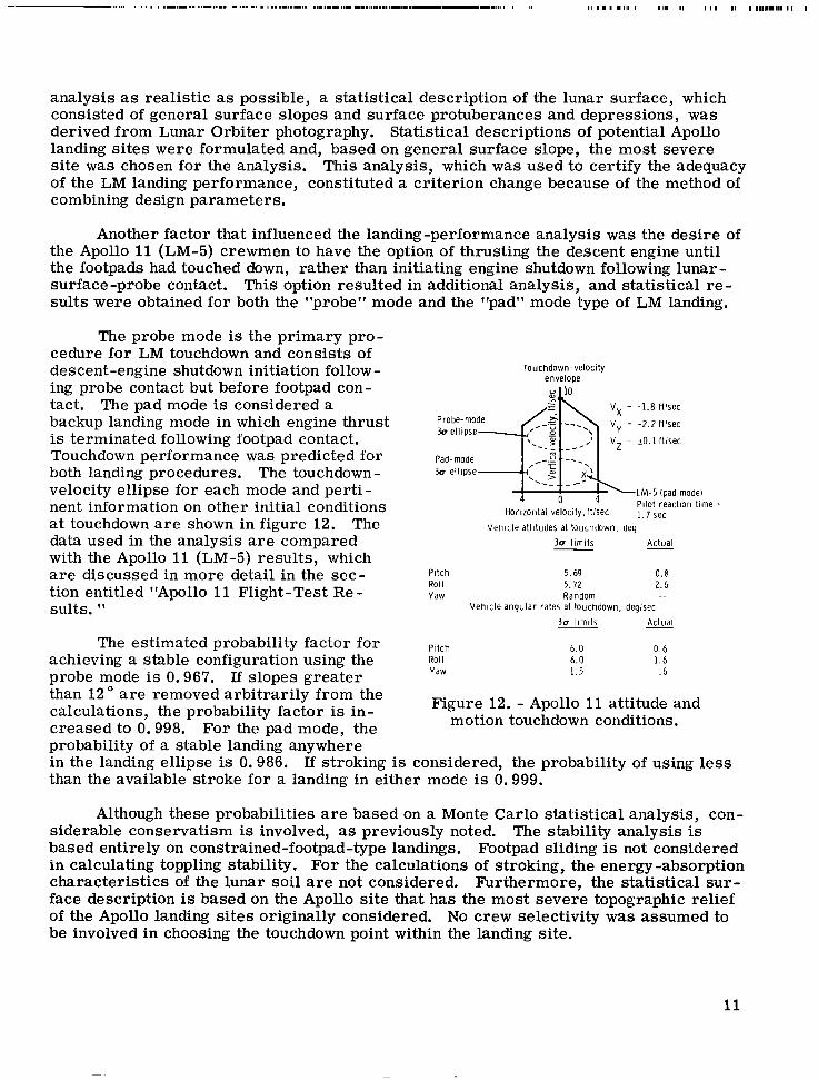
The probe mode is the primary pro- cedure for LM touchdown and consists of descent-engine shutdown initiation follow - ing probe contact but before footpad con- tact. The pad mode is considered a backup landing mode in which engine thrust is terminated following footpad contact. Touchdown performance was predicted for both landing procedures. The touchdown- velocity ellipse for each mode and perti- nent information on other initial conditions at touchdown a r e shown in figure 12. data used in the analysis are compared with the Apollo 11 (LM-5) results, which are discussed in more detail in the sec- tion entitled "Apollo 11 Flight-Test Re- sults. "
The
The estimated probability factor for achieving a stable configuration using the probe mode is 0.967. If slopes greater than 12" a r e removed arbitrarily from the calculations, the probability factor is in- creased to 0.998. For the pad mode, the probability of a stable landing anvwhere
Touchdown-velocity envelope
-1.8 ftlsec
-2.2 ft fsec
io. 1 ftlsec
.LM-5 (pad model Pilot reaction time =
1.1 sec Vehic le altitudes at touchdown, deg
3 0 l imi ts Actual -
Pitch 5.69 0.8 Roll 5.72 2.6 Yaw Random .-
Vehicle angular rates at touchdown. deglsec 3u l imits - Actual
P i tch Roll Yaw
6.0 0.6 6.0 1.6 1.5 .6
Figure 12. - Apollo 11 attitude and motion touchdown conditions.
in the landing ellipse is 0.986. if stroking is considered, the probability of using less than the available stroke for a landing in either mode is 0.999.
Although these probabilities are based on a Monte Carlo statistical analysis, con- siderable conservatism is involved, as previously noted. The stability analysis is based entirely on constrained-footpad-type landings. Footpad sliding is not considered in calculating toppling stability. For the calculations of stroking, the energy -absorption characteristics of the lunar soil are not considered. Furthermore, the statistical sur- face description is based on the Apollo site that has the most severe topographic relief of the Apollo landing sites originally considered. No crew selectivity was assumed to be involved in choosing the touchdown point within the landing site.
11
Thermal Insulation Landing-gear thermal-insulation design is based on several requirements,
Landing-gear temperatures must be maintained at or below design levels to ensure pos- itive structural margins of safety and proper mechanical operation during deployment and landing. l imits is necessary to ensure that the crush loads will be within proper levels.
Temperature control of the honeycomb energy absorbers within specified
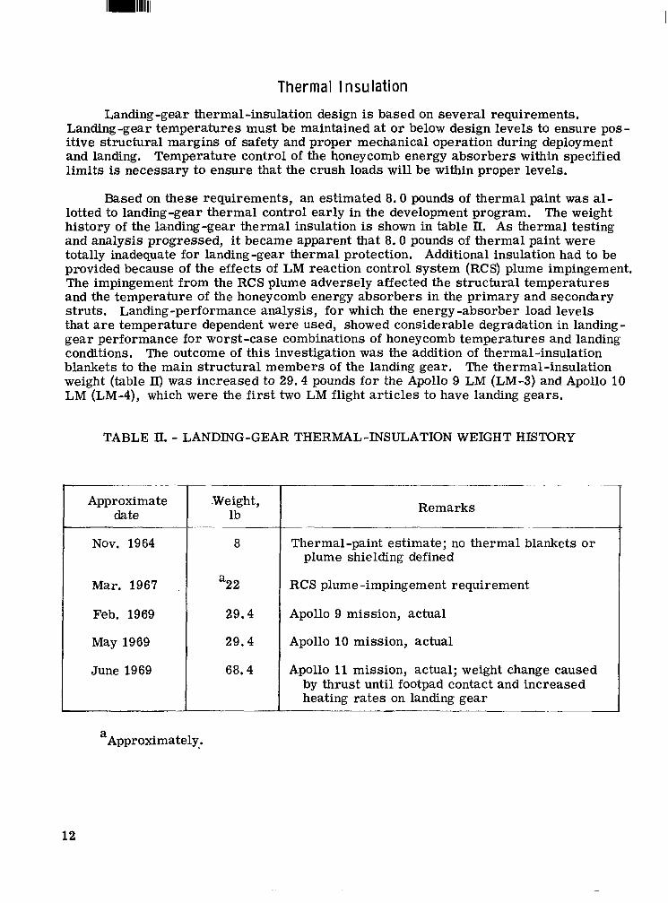
Based on these requirements, an estimated 8.0 pounds of thermal paint was al- lotted to landing-gear thermal control early in the development program. The weight history of the landing-gear thermal insulation is shown in table II. As thermal testing and analysis progressed, i t became apparent that 8.0 pounds of thermal paint were totally inadequate for landing -gear thermal protection. Additional insulation had to be provided because of the effects of LM reaction control system (RCS) plume impingement, The impingement from the RCS plume adversely affected the structural temperatures and the temperature of the honeycomb energy absorbers in the primary and secondary struts. Landing-performance analysis, fo r which the energy -absorber load levels that are temperature dependent were used, showed considerable degradation in landing- gear performance for worst -case combinations of honeycomb temperatures and landing conditions. The outcome of this investigation was the addition of thermal-insulation blankets to the main structural members of the landing gear. The thermal-insulation weight (table II) was increased to 29.4 pounds for the Ap0110 9 LM (LM-3) and Apollo 10 LM (LM-4), which were the first two LM flight art icles to have landing gears.
TABLE II. - LANDING-GEAR THERMAL-INSULATION WEIGHT HISTORY
Approximate date
Nov. 1964
Mar. 1967
Feb. 1969
May 1969
June 1969
.Weight, lb
8
“22
29.4
29.4
68.4
-- ~~ - . .-
Remarks
Thermal-paint estimate; no thermal blankets o r plume shielding defined
RCS plume -impingement requirement
Apollo 9 mission, actual
Apollo 10 mission, actual
Apollo 11 mission, actual; weight change caused by thrust until footpad contact and increased heating rates on landing gear
a Approximately.
12
Another significant thermal-design problem related to the landing gear was the effect of descent-engine-plume heating. A few months before the flight of Apollo 11, data from scale-model shock-tube tests indicated that heating rates on the landing gear were much higher than previously had been considered for design. sulted in an extensive effort to design additional thermal insulation for the landing gear and to perform structural and mechanical tests on the affected hardware.
This increase re-
At approximately the time the problem of excessive heating rates was identified, the LM flight crew expressed a desire to have the option of using either the pad mode o r the probe mode. Inclusion of the pad mode resulted in even higher predicted heating rates for the landing gear. Consequently, the Apollo 11 landing-gear thermal-insulation weight was increased 39 pounds over that of Apollo 10. A more refined analysis allowed reduction of the landing-gear -insulation weight on subsequent vehicles.
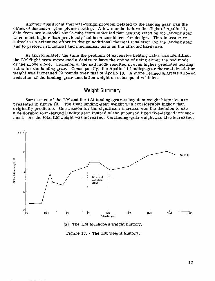
Weight Sum ma ry
Summaries of the LM and the LM landing-gear-subsystem weight histories are presented in figure 1'3. The final landing-gear weight w a s considerably higher than originally predicted. One reason for the significant increase was the decision to use a deployable four -legged landing gear instead of the proposed fixed five -1eggedarrange- ment. As the total LM weight w a s increased, the landing -gear weight was also increased.
- L I L 1
1963 1964 1965 1966 1967 1968 10 I 1962
Calendar year
(a) The LM touchdown weight history.
1 I
1969 1970
Figure 13. - The LM weight history.
13
LM weight-
-1 txxd$on Apollo 9 Apollo 10
- - 4 0 0
proposal -1 - L
1962 1963 1964 1965 1966 1967 1968 1969 1 -~
1970 300
Calendar year
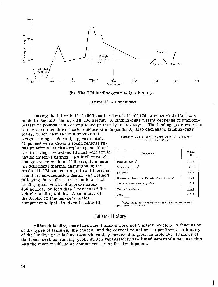
(b) The LM landing-gear weight history.
Figure 13. - Concluded.
During the latter half of 1965 and the f i rs t half of 1966, a concerted effort was made to decrease the overall LM weight. A landing-gear weight decrease of approxi- mately 75 pounds was accomplished primarily in two ways. to decrease structural loads (discussed in appendix A) also decreased landing -gear
The landing-gear redesign
loads, which resulted in a substantial weight savings. Second, approximately 40 pounds were saved throughgeneral re- design efforts, such as replacing machined s t ruts having riveted end fittings with struts having integral fittings, No further weight changes were made until the requirements for additional thermal insulation on the Apollo 11 LM caused a significant increase. The thermal -insulation design w a s refined following the Apollo 11 mission to a final landing-gear weight of approximately 456 pounds, o r less than 3 percent of the vehicle landing weight. A summary of the Apollo 11 landing-gear major- component weights is given in table III.
TABLE Ill. - APOLLO 11 LANDING-GEAR-COMPONENT WEIGHT SUMMARY
Component
Primary strutsa
Secondary strutsa
Footpads
Deployment t russ and deployment mechanisms
Lunar-surface -sensing probes
Thermal insulation
Total
Weight, lb
211.3
68. 8
44.9
80.4
6. I
68.4
486.5
-
aTota.l honeycomb-energy-absorber weight in a l l struts i s approximately 61 bounds.
Failure History
Although landing-gear hardware failures were not a major problem, a discussion of the types of failures, the causes, and the corrective actions is pertinent. A history of the landing-gear failures and where they occurred is given in table IV. Failures of the lunar -surface -sensing-probe switch subassembly a r e listed separately because this was the most troublesome component during the development.
14
I
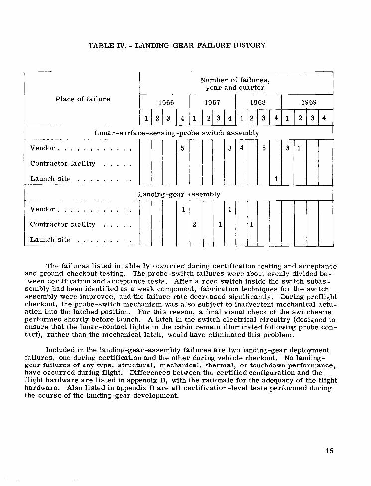
TABLE IV. - LANDING-GEAR FAILURE HISTORY
~ - . I 1966 I 1967 1 1968
j ij213 j.+ 12131411j21i14
I I
1969
1 2 1 3 j 4 . . . . . . . . . . . .
. . . . . . . . . . . . . .
. .
Vendor 5
Contractor facility
Launch site - - .~ ~ - . .~
5 3 1
1 A ’ 1 ’ - ..
I Landing -gear assembly I
L ~ ~ - ~ -. .~ ~- . . . _ -__
The failures listed in table IV occurred during certification testing and acceptance and ground-checkout testing. The probe-switch failures were about evenly divided be - tween certification and acceptance tests. After a reed switch inside the switch subas- sembly had been identified as a. weak component, fabrication techniques for the switch assembly were improved,. and the failure rate decreased significantly. During preflight checkout, the probe-switch mechanism w a s also subject to inadvertent mechanical actu- ation into the latched position. performed shortly before launch. A latch in the switch electrical circuitry (designed to ensure that the lunar-contact lights in the cabin remain illuminated following probe con- tact), rather than the mechanical latch, would have eliminated this problem.
For this reason, a final visual check of the switches.is
- . -.
Vendor . . . . . . . . . . . . Contractor facility . . . . . Launch site . . . . . . . . . I - -~ ... . -
Included in the landing -gear -assembly failures a r e two landing -gear deployment failures, one during certification and the other during vehicle checkout. No landing - gear failures of any type, structural, mechanical, thermal, o r touchdown performance, have occurred during flight. flight hardware a r e listed in appendix B, with the rationale for the adequacy of the flight hardware. Also listed in appendix B a r e all certification-level tests performed during the course of the landing -gear development.
Differences between the certified configuration and the
~ . . - .. ~.
1
. . . . .
15
APOLLO 11 FLIGHT-TEST RESULTS
The initial landing of an LM on the lunar surface constituted the first complete flight test of the landing-gear hardware. Landing-gear deployment in space had been demonstrated on two previous manned LM flights, Apollo 9 and 10. Before the Apollo 11 mission, LM landing performance and landing-gear functional operation had been dem - onstrated by analysis and by extensive ground tests. During these tests, the landing gear was exposed to all significant flight environments, including vehicle drop tes ts un- der simulated lunar-gravity conditions.
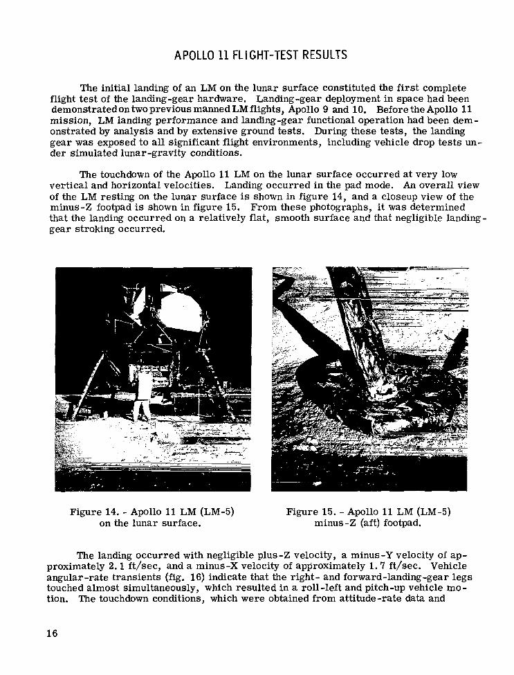
The touchdown of the Apollo 11 LM on the lunar surface occurred at very low vertical and horizontal velocities. of the LM resting on the lunar surface is shown in figure 14, and a closeup view of the minus-Z footpad is shown in figure 15. that the landing occurred on a relatively flat, smooth surface and that negligible landing- gear stroking occurred.
Landing occurred in the pad mode. An overall view
From these photographs, it was determined
Figure 14. - Apollo 11 LM (LM-5) on the lunar surface.
Figure 15. - Apollo 11 LM (LM-5) minus -Z (aft) footpad.
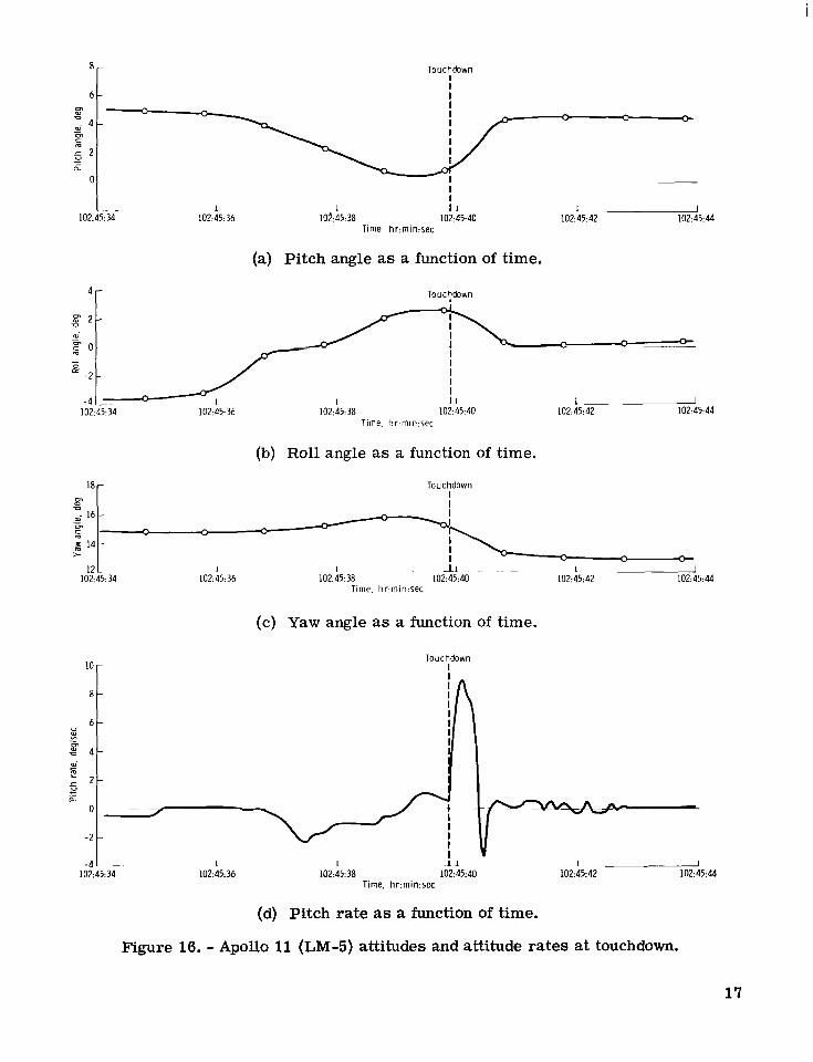
The landing occurred with negligible plus-Z velocity, a minus-Y velocity of ap- proximately 2 . 1 ft/sec, and a minus-X velocity of approximately 1 . 7 ft/sec. Vehicle angular-rate transients (fig. 16) indicate that the right- and forward-landing-gear legs touched almost simultaneously, which resulted in a roll-left and pitch-up vehicle mo - tion. The touchdown conditions, which were obtained from attitude-rate data and
16
8-
6 - m 0
c - m
- c 4 -
- 5 2 - ._ a 0
I - - 1 1 i 1 102:45: 34 102:45:36 102:45:38 102:45:40
Time, hr:min:sec
Touchdown I I I I ,. - - - * - -
I I
(a) Pitch angle as a function of time.
4r Touc?down
1 - 102:45:42 102:45: 44
Time, hr:min:sec
(b) Roll angle as a function of time.
Touchdown 18 r- I I I
I I
1 2 L 1 1 I 1 ~ ~~ ~ 1 I 102:45:34 102:45:36 102:45:38 102:45:40 102:45:42 102:45:44
10
8
6 a3 - E 4 a3.
E 5 k i
- 2
c
0
-2
- 4 102
Time, hr.min:sec
(c) Yaw angle as a function of time.
Touchdown I
- I I -1 1 1 - : 34 102:45:36 102:45:38 102:45:40 102:45:42 102:45:44
Time. h r m i n : s e c
(d) Pitch rate as a function of time.
Figure 16. - Apollo 11 (LM-5) attitudes and attitude rates at touchdown.
17
m d L
:-2 B
- -
-4 -
-6 -
-8 3 102:45:M 102: 45: 36 102:45:38 102:45:40 102:45:42 102:45:44
Time, hr:min:sec
(e) Roll rate as a function of time.
Touchdown I I I I I
- 4 1 - L-- - I I I 102:45: 34 102:45: 36 102:45:38 102:45:40 102:25:4.?
Time. hr:min:sec
I 102:45:44
(f) Yaw rate as a function of time.
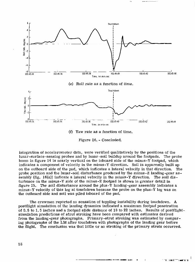
Figure 16. - Concluded.
integration of accelerometer data, were verified qualitatively by the positions of the lunar-surface-sensing probes and by lunar -soil buildup around the footpads. boom in figure 14 is nearly vertical on the inboard side of the minus-Y footpad, which indicates a component of velocity in the minus-Y direction. Soil is apparently built up on the outboard side of the pad, which indicates a lateral velocity in that direction. The probe position and the lunar-soil disturbance produced by the minus-Z landing-gear as- sembly (fig. 16(a)) indicate a lateral velocity in the minus-Y direction. The soil dis- turbance on the minus-Y side of the minus-Z footpad is shown in greater detail in figure 15. The soil disturbance around the plus-Y landing-gear assembly indicates a minus-Y velocity of this leg at touchdown because the probe on the plus-Y leg was on the outboard side and soil was piled inboard of the pad.
The probe
The crewmen reported no sensation of toppling instability during touchdown. A postflight simulation of the landing dynamics indicated a maximum footpad penetration of 0.5 to 1. 5 inches and a footpad slide distance of 18 to 22 inches. Results of postflight- simulation predictions of s t rut stroking have been compared with estimates derived from the landing-gear photographs, Primary -strut stroking was estimated by compar - ing photographs of the LM after touchdown with photographs of the landing gear before the flight. The conclusion was that little o r no stroking of the primary struts occurred.
18
- ,.I1111111 111.1.11 I,,,,, I I1 I
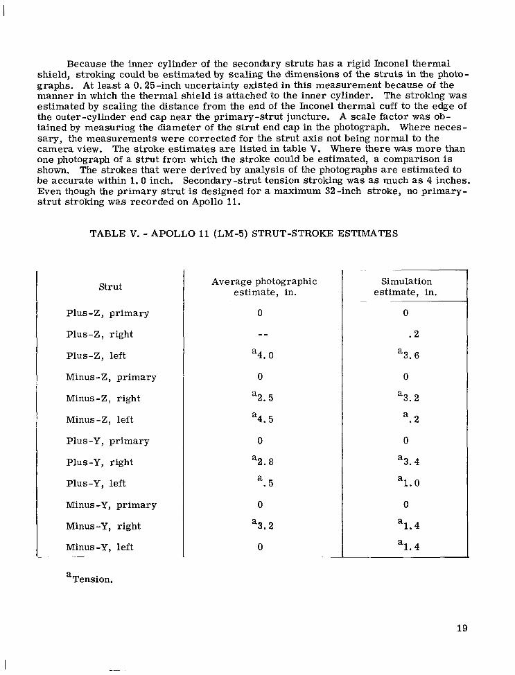
Because the inner cylinder of the secondary struts has a rigid Inconel thermal shield, stroking could be estimated by scaling the dimensions of the s t ruts in the photo- graphs. At least a 0.25-inch uncertainty existed in this measurement because of the manner in which the thermal shield is attached to the inner cylinder. The stroking was estimated by scaling the distance from the end of the Inconel thermal cuff to the edge of the outer-cylinder end cap near the primary-strut juncture. A scale factor was ob- tained by measuring the diameter of the strut end cap in the photograph. Where neces- sary, the measurements were corrected for the strut axis not being normal to the camera view. The stroke estimates are listed in table V. Where there was more than one photograph of a s t rut from which the stroke could be estimated, a comparison is shown, be accurate within 1.0 inch. Secondary-strut tension stroking was as much as 4 inches. Even though the primary s t rut is designed for a maximum 32-inch stroke, no primary- s t rut stroking was recorded on Apollo 11.
The strokes that were derived by analysis of the photographs a r e estimated to
TABLE V. - APOLLO 11 (LM-5) STRUT-STROKE ESTIMATES
Strut
Plus-Z, primary
Plus-Z, right
Plus-Z, left
Minus-Z, primary
Minus-Z, right
Minus-Z, left
Plus -Y, primary
Plus-Y, right
Plus-Y, left
Minus -Y, primary
Minus -Y, right
Minus -Y, left
a Tension.
Average photographic estimate, in.
0
--
4.0
0
a
“2.5
4.5
0
“2.8 a . 5
0
“3.2
0
a
Simulation estimate, in.
0
. 2
‘3.6
0
3.2
. 2 a
0
a
“3.4
1 .0
0
1.4
1.4
a
a
a
19
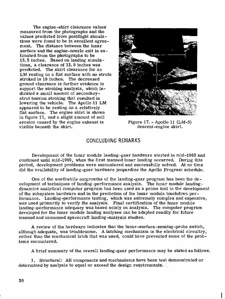
The engine-skirt clearance values measured from the photographs and the values predicted from postflight simula- tions were found to be in excellent agree- ment, The distance between the lunar surface and the engine-nozzle exit is es- timated from the photographs to be 13. 5 inches. Based on landing simula- tions, a clearance of 13.8 inches was predicted. The skir t clearance for an LM resting on a flat surface with no s t ruts stroked is 19 inches. ground clearance is further evidence to support the stroking analysis, which in- dicated a small amount of secondary- s t rut tension stroking that resulted in lowering the vehicle. appeared to be resting on a relatively flat surface. The engine skirt is shown in figure 17, and a slight amount of soil erosion caused by the engine exhaust is visible beneath the skirt.
The decreased
The Apollo 11 LM
Figure 17. - Apollo 11 (LM-5) descent-engine skirt.
CONCLUDING REMARKS
Development of the lunar module landing-gear hardware started in mid-1962 and continued until mid-1969, when the first manned lunar landing occurred. During this period, development problems were encountered and successfully solved. At no time did the availability of landing-gear hardware jeopardize the Apollo Program schedule.
One of the worthwhile outgrowths of the landing-gear program has been the de- The lunar module landing - velopment of techniques of landing -performance analysis.
dynamics analytical computer program has been used as a prime tool in the development of the subsystem hardware and in the prediction of the lunar module touchdown per- formance. Landing-performance testing, which was extremely complex and expensive, was used primarily to verify the analysis. landing -performance adequacy was based solely on analysis. The computer program developed for the lunar module landing analyses can be adapted readily for future manned and unmanned spacecraft landing-analysis studies.
Final certification of the lunar module
A review of the hardware indicates that the lunar -surface -sensing-probe switch, although adequate, w a s troublesome. A latching mechanism in the electrical circuitry, rather than the mechanical latch that was used, could have prevented some of the prob- lems encountered.
A brief summary of the overall landing-gear performance may be stated as follows.
1. Structural: All components and mechanisms have been test demonstrated or determined by analysis to equal o r exceed the design requirements. .',
20
I
2. Mechanical: All mechanisms have been functionally test demonstrated to be adequate under lunar -mission environments.
3. Landing performance: For the Apollo landing sites, the energy-absorption and toppling-stability capabilities are adequate. The probability of never attaining max- imum strut stroking is greater than 0.999, and the probability of attaining a stable land- ing on a slope of 12" or less is 0.998.
Manned Spacecraft C enter National Aeronautics and Space Administration
Houston, Texas, January 6, 1972 914 -13 -20 -13 -72
REFER EN C ES
1. Anon. : Contract Technical Specification for Lunar Module Systems. Rept. LSP-470-1D, Grumman Aircraft Engineering Corp. , Oct. 1, 1968.
2. Anon. : Design Criteria and Environments - LM. Rept. LED-520-1 H, Grumman Aircraft Engineering Corp. , Oct. 19, 1970.
3. Anon. : IIIB LEM Lunar Landing Simulation Studies. Rept. LED-470-5, Grumman Aircraft Engineering Corp., Feb. 18, 1966.
21
APPENDIX A
LAND I NG PERFORMANCE OF THE L M
Landing dynamics was a major concern during the development of the LM. The LM touchdown-performance characteristics must be compatible with both a broadly de - fined lunar surface and the LM control-system characteristics. Furthermore, the LM must be capable of landing under conditions of zero visibility.
Because of the difficulty in conducting meaningful and comprehensive full -scale landing -performance tests in the earth -gravity environment, an extensive landing- dynamics analysis, in which digital -computer simulations were used, was the primary tool for proving the adequacy of the landing gear for both toppling stability and landing- gear energy -absorption capability, much of the structural and mechanical testing. Results of both the development testing and the performance analysis were used to develop an optimum landing gear that ful- filled the design requirements. Analysis of the landing-gear performance also consti- tuted a major portion of the flightworthiness certification.
This analysis was conducted concurrently with
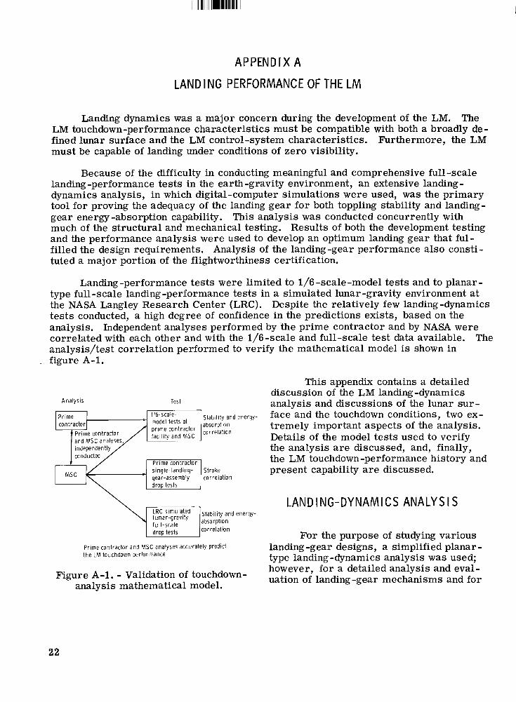
Landing-performance tests were limited to 1/6 -scale-model tests and to planar - type full -scale landing-performance tests in a simulated lunar -gravity environment at the NASA Langley Research Center (LRC). Despite the relatively few landing-dynamics tes ts conducted, a high degree of confidence in the predictions exists, based on the analysis. Independent analyses performed by 'the prime contractor and by NASA were correlated with each other and with the 1/6-scale and full-scale test data available. analysis/test correlation performed to verify the mathematical model is shown in figure A-1.
The
This appendix contains a detailed discussion of the LM landing-dynamics analysis and discussions of the lunar sur - face and the touchdown conditions, two ex- tremely important aspects of the analysis. Details of the model tests used to verify the analysis are discussed, and, finally, the LM touchdown-performance history and
Test Analysis
Stability and energy-
Pr ime contractor - single-landing- Stroke present capability are discussed.
LAND I NG-DY N A M l CS ANALY S I S
For the purpose of studying various landing -gear designs, a simplified planar - type landing-dynamics analysis was used; however, for a detailed analysis and eval- uation of landing-gear mechanisms and for
Prime contractor and MSC analyses accurately predlct t he t M touchdown performance
Figure A-1. - Validation of touchdown- analysis mathematical model.
22
providing design information for landing-load determinations and landing -gear - performance predictions, a three -dimensional landing-dynamics computer program was required. The following description of the LM landing-dynamics computer pro- gram is typical of the analyses used for landing studies. Detailed descriptions of the prime contractor analysis may be found in references A-1 and A-2, and a description of the NASA Manned Spacecraft Center analysis is given in reference A-3.
Two basic requirements of the analysis were that it must realistically model the geometry and loading of the individual landing-gear members and that it must be capa- ble of accommodating a wide variety of lunar -surface conditions. studies, the LM, except for the landing gear, is considered to be a rigid body. An un- sprung mass represents the mass of the footpad and the primary strut. and secondary struts stroke axially and absorb energy according to the load,/stroke curves shown in figures 7 and 9. the purpose of determining the landing-gear geometry that results from stroking. Strut elasticity is introduced to the extent that it affects the overall vehicle motion.
For landing -dynamics
The primary
The struts a r e considered to be rigid in flexure for
The energy absorption that results when a strut is stroked axially is incorpo- rated in the model by assuming an elastic -plastic load/stroke characteristic. Energy, which is represented by the elastic portion of the curve, is released back into the sys- tem because of the axial elasticity of the strut. loads caused by transverse inertia a r e assumed to be negligible; therefore, the second- a ry struts a r e only loaded axially. primary-strut bearing loads that must be accounted for in the stroking analysis. load/stroke curve for each s t rut may vary because of manufacturing tolerances, strut- stroking velocity, and honeycomb temperatures. For this reason, the analysis enables different honeycomb characteristics to be assigned to each strut.
For the secondary struts, bending
The secondary-strut side loads cause sizable The
The lunar surface at the touchdown point may have a general slope as well as various combinations of protuberances and depressions. acteristics, a footpad may be subjected to sliding-friction forces o r to full constraint. Surface forces normal to the 'footpad a r e assumed to be elastic-plastic. In addition, footpad loads caused by lateral crushing are represented for cases in which the footpad slides into a rigid obstacle. a single landing simulation.
Because of the surface char -
Combinations of footpad conditions can be represented in
Other significant effects are included in the analysis. Control moments caused Because it is possible for the descent-engine noz- by RCS thrusting may be included.
zle extension to impact the lunar surface, the load/stroke characteristics of the crush- able nozzle are included. Nozzle energy -absorption characteristics are based on tests of full-scale engine skirts. In addition to the descent-engine thrust, considerable forces may be exerted by the interaction of the descent-engine exhaust plume with the lunar surface, which causes surface-effect forces on the base of the vehicle. Signifi- cant engine thrust may occur with the nozzle close to the lunar surface because of the long thrust-decay time or because the pilot may choose to touch down with the engine on. A landing on top of a large protuberance o r mound would place the nozzle close to the surface. With the nozzle thrusting close to the surface, a thrust-amplification ef- fect occurs. This effect has a sizable influence on the LM toppling-stability character- istics and is accounted for in the analysis.
23
The vehicle c. g. has six degrees of freedom, three translational and three ro- tational. In addition, each footpad has three translational degrees of freedom. A total of 18 nonlinear, second-order, simultaneous differential equations of motion must be integrated to describe the vehicle dynamics. Results of a landing simulation include time histories of the rigid-body vehicle positions, velocities, and accelerations. In ad- dition, footpad motion, s t rut loads, and s t rut strokes a r e obtained. The toppling sta- bility of the vehicle is also monitored, The vehicle is assumed to be stable neutrally if the vehicle tips to a point at which the vehicle c. g. coincides with the vertical plane that passes through the center of any two adjacent footpads. ity and the distance between the vehicle mass center and the vertical plane are meas- ures of the vehicle stability. If the vehicle stability and s t rut strokes a r e known, landing -gear performance evaluations can be made.
The vehicle tipping veloc-
During the early stages of the landing-gear analysis, it was discovered that cer - qtain types of landings tend to be critical with respect to the vehicle stability o r the stroking of a particular strut. Although these particular landings could not be judged to be worst-case landings, they were the worst cases found and were considered to be good indicators of the adequacy of the particular landing-gear configuration being studied. These landing cases were called control runs and were used extensively for evaluation of the landing-gear designs. As analysis work continued, a more realistic look at landing performance was desired, which resulted in several statistical studies. The basic analysis for the statistical studies was the same as that used for the dis- crete analyses. Statistical representations of the lunar surface, spacecraft initial con- ditions at touchdown, and pertinent parameters (such as descent-engine thrust-decay time histories) were used in the statistical analyses.
LUNAR-SURFACE DESCRI PTION
To design an LM landing system, the surface on which the LM is to touch down must be defined. At the time the contract to produce a lunar-landing vehicle was awarded, only meager information was available concerning the lunar -surface top0 - graphical features and soil characteristics. Therefore, a surface had to be assumed that not only was reasonable but also was broad enough to accommodate a wide range of actual landing sites. A specification of the lunar surface was formulated, and, based on this specification, the landing gear was designed and manufactured.
The original lunar-surface description (refs. 1 and 2) consisted of the topograph- ical and soil-property features defined in the section of this report entitled "Design Re- quirements and Criteria. '' A comprehensive soil-mechanics study (ref. A-4) was conducted in support of the LM landing analysis. formulated for various statistical studies of landing performance and for landing -load analysis. The statistical description used most extensively was based on topographical data from the Lunar Orbiter photography of the most severe Apollo landing site (fig. A-2). With the exception of one study, no attempt was made to establish statisti- cal values for soil properties. In general, the footpads were considered to be fully constrained for all studies, except for secondary-strut tension stroking for which a low friction coefficient is a crucial parameter. Although the specification defined 0.4 as the minimum value for the friction coefficient, lower values were investigated in secondary -strut strokeout studies.
Statistical descriptions were also
24
Slope. deg Protuberance, m
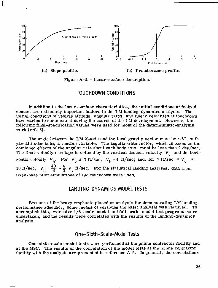
(a) Slope profile. (b) Protuberance profile.
Figure A-2. - Lunar-surface description.
TOUCHDOWN CONDITIONS
111 addition to the lunar-surface characteristics, the initial conditions at footpad contact are extremely important factors in the LM landing-dynamics analysis. The initial conditions of vehicle attitude, angular rates, and linear velocities at touchdown have varied to some extent during the course of the LM development. However, the following final-specification values were used for most of the deterministic-analysis work (ref. 3).
The angle between the LM X-axis and the local gravity vector must be 5 6", with yaw attitudes being a random variable. The angular-rate vector, which is based on the combined effects of the angular rate about each body axis, must be less than 2 deg/sec. The final-velocity envelope is defined by the vertical descent velocity Vv and the hori-
zontal velocity Vh.
10 ft/sec, vh = - 40 fixed-base pilot simulations of LM touchdown were used.
For V 5 7 ft/sec, Vh = 4 ft/sec; and, for 7 ft/sec 5 Vv 5 V
Vv ft/sec. For the statistical landing analyses, data from 3 - 3
LANDING-DYNAMICS MODEL TESTS
Because of the heavy emphasis placed on analysis for demonstrating LM landing- performance adequacy, some means of verifying the basic analysis was required. To accomplish this, extensive 1/6 -scale-model and full-scale -model test programs were undertaken, and the results were correlated with the results of the landing-dynamics analysis.
On e- S ixt h- Sca I e- Mode I Tests
One -sixth-scale -model tests were performed at the prime contractor facility and at the MSC. The results of the correlation of the model tests at the prime contractor facility with the analysis are presented in reference A-5. In general, the correlations
25
for vehicle stability and landing-gear energy absorption were considered to be the most important. Instrumentation of the models permitted comparisons of acceleration, ve - locity, and displacement time histories with the analytical results.
By using the technique of dynamic scaling, a model was designed that could be tested in the earth-gravity environment. 1/6-dimensional scale and a (1/6) mass scale, and the ratio of the model touchdown velocities to the touchdown velocities of the full-scale LM was 1.0. desirable characteristics of being untethered, of having a convenient size and weight for handling, and of having easily obtainable mass properties. Scale parts, including landing -gear energy absorbers, generally presented no great manufacturing problem. However, the fabrication of reliable 1/6 -scale honeycomb cartridges was an initial problem. The small number of cells in the scale cartridges caused cartridge instabil- ity during stroking, which resulted in poor load/stroke characteristics. The final test cartridges were handmade and contained a sufficient number of cells to provide repeat- able load/stroke characteristics.
The resulting model was constructed to a 3
The model had the
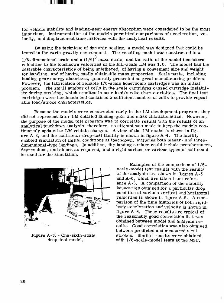
Because the models were constructed early in the LM development program, they did not represent la ter LM detailed landing-gear and mass characteristics. However, the purpose of the model test program was to correlate results with the results of an analytical touchdown analysis; therefore, no attempt was made to keep the models con- tinuously updated to LM vehicle changes. A view of the LM model is shown in fig- ure A-3, and the contractor drop-test facility is shown in figure A-4. The facility enabled simulation of initial conditions at touchdown, including both planar - and three - dimensional-type landings. In addition, the landing surface could include protuberances, depressions, and slopes as required, and a rigid surface o r various types of soil could be used for the simulation.
Figure A-3. - One-sixth-scale drop-test model.
Examples of the comparison of 1/6- scale-model test results with the results of the analysis a r e shown in figures A-5 and A-6, which are taken from refer- ence A-5. A comparison of the stability boundaries obtained for a particular drop condition at various vertical and horizontal velocities is shown in figure A-5. A com- parison of the time histories of both rigid- body acceleration and velocity is shown in figure A-6. These results are typical of the reasonably good correlation that was obtained between model and analysis re- sults. Good correlation was also obtained between predicted and measured strut strokes. Similar results were obtained with 1/6-scale-model tests at the MSC.
26
The scale model impacted wi th a 2-2 landing-year configu- rat ion and wi th the nose u p 5". The impacted surface had a 5' 0 downhil l slope, wi th &in. depressions in the area of forward-landing-year impact and with the footpads fu l ly constrained at impact.
C
Stable 0
0 . I
1 I I I ' 2 4 6 8 10
I 0
Horizontal velocity. Vh. f t h C 12
Figure A-4. - One-sixth-scale model Figure A-5. - One-sixth-scale-model te st/analy s is gross correlation for and drop -test equipment at the
prime contractor facility. symmetrical drops.
- Experimental ---- Analytical
O t \-,---
I I I- 40f) 40 80 120 lk 2h l 2:O 2 i O 3iO 3dO
Time. msec Time. msec
(a) Horizontal velocity as a function of time.
(b) Vertical velocity as a function of time.
Figure A-6. - One-sixth-scale-model test/analysis time-history correlation for symmetrical drops.
27
I IIIIIIII 111llmll11111l111
-----Analytical
I I I 1 1 1 1 1 1 4L I I I I I I I I I 0 40 80 120 164 200 240 280 320 360 0 40 go 120 160 m 240 280 320 360
-12 I Time. msec Time, msec
(c) Horizontal acceleration as a function of time.
(d) Vertical acceleration as a function of time.
Figure A-6. - Concluded.
Full-Scale-Model Tests
In addition to the 1/6 -scale -model tests, a ser ies of tests was performed using a fgU-scale mass representation of the LM and a preproduction 167-inch-tread-radius $antilever-type landing gear. These tests were performed at LRC in a simulated lunar- gravity environment. 'was suspended from cables, onto an in- clined plane, The plane was tilted at an "angle that provided one-sixth earth gravity normal to the vehicle landing surface. The 'remaining weight of the vehicle was nulli- hed by supporting cables. Twenty-one drop tests were conducted in the ser ies using the vehicle shown in figure A-7. The lunar -gravity -simulation touchdown surface is also shown in figure A-7. Re- sults of the LRC test program and some comparisons of the test data with analyt- ical predictions are presented in refer- ences A-6 and A-?.
The lunar gravity was simulated by dropping the model, which
Although these tests were restricted to planar-type landings, much useful in- formation was obtained relative to the functional characteristics of the landing gear. The tests provided increased con- fidence in the LM-landing-gear functional operation and also provided test data for stability and energy -absorption evaluation.
Figure A-7. - Simulated-lunar -gravity test vehicle and related equipment at the LRC.
28
Consideration was given to conducting simulated-lunar -gravity tests at the prime contractor facility, These tests would permit unsymmetrical-type landing simulations; however, this kind of test was not conducted because the high cost would not justify the limited amount of information that would have been gained. Numerous development problems encountered during the design of the lunar -gravity -simulation portion of the test equipment also contributed to the decision to cancel these tests.
LANDING PERFORMANCE
The landing-performance analysis has been used extensively as a tool in the LM landing -gear design and performance evaluation. Eanding-gear performance studies may be roughly divided into two categories: the deterministic- or worst-case-type analysis that was used for landing-gear design and early performance evaluations, and the statistical or Monte Carlo analysis that w a s used to predict the probability of a suc- cessful landing.
Determin is t ic Landing Ana lysis
In initial design studies, only landings in which the vehicle c. g. motion was planar were considered. rical landings. and one trailing landing gear was designated the 1-2-1 case. The case with two landing gears leading and two trailing is called the 2-2 case. In general, for symmetrical land- ings, the 2 -2 case is stability critical, and the 1-2 -1 case is critical for priniary-strut energy -absorption requirements.
Two landing-gear orientations were considered for symmet- The orientation with one leading landing gear, two side landing gears,
As the analysis was refined, unsymmetrical-type landings were considered. Two of the more important parameters in unsymmetrical-type landings a r e yaw attitude and the vehicle flight-path angle. Typical unsymmetrical landing performances, which a r e based on a s e t of critical landings, a r e summarized in figures 10 and 11. The vehicle orientation and the lunar -surface conditions for critical stability, primary-strut stroke, secondary -strut compression stroke, and secondary-strut tension stroke a r e shown in figure 11. The stability and secondary-strut stroke boundaries a r e critical for unsym- metrical landings. The primary-strut stroke is critical for the symmetrical 1-2 -1 land- ing case. The velocity envelope shown in figure 10 was the envelope chosen for design purposes in mid-1965 and is described in the section of this report entitled "Statistical Landing Performance. "
Based on an LM touchdown weight of 16 000 earth pounds, the kinetic energy in- volved in a landing with a lO-ft/sec vertical velocity would be approximately 26 000 ft-lb. An additional energy contribution is provided by the potential energy. 8000 ft-lb of potential energy could be involved as a result of a vehicle c. g. displace- ment of 3 feet from a combination of landing-gear stroking, vehicle touchdown attitude, and surface topography. One landing-gear assembly, which consists of all energy- absorption capability in the primary strut and the two secondary struts, is equivalent to approximately 30 870 ft-lb (21 200 ft-lb in the primary s t rut and 9670 ft-lb in the sec- ondary struts (5170 ft-lb in tension and 4500 ft-lb in compression)). The distribution of
For example,
29
energy absorption for each landing-gear leg depends on many factors during the land- ing, but the value for the energy-absorption capability of each landing gear corresponds approximately to the design requirement for total energy absorption.
Stati stica I Landing Analysis
The analytical landing performance was based on combining touchdown initial conditions and lunar -surface conditions in an effort to obtain worst-case simulations. Because of the large number of parameters involved, it was not practical to establish with absolute certainty the worst possible combinations of parameters; therefore, to show that the worst-case design conditions constituted an extremely severe basis for performance evaluation, a statistical analysis of the landing -performance problem w a s conducted.
For the initial statistical analysis, the four critical measurements of landing -gear performance (stability, primary-strut stroke, secondary -strut tension stroke, and secondary -strut compression stroke) were considered separately (refs. A-3 and A-8). This approach was taken to produce a conservative statistical analysis, because param - eters that are conservative for one performance measurement are not necessarily con- servative for another. For example, a low value for the footpad/soil friction coefficient may be critical for secondary -strut tension strokeout but not for vehicle stability, where full footpad constraint is the critical parameter. A summary of the major landing-gear performance analyses that were completed before the Apollo 11 lunar landing in July 1969 is contained in table A-I.
30
I
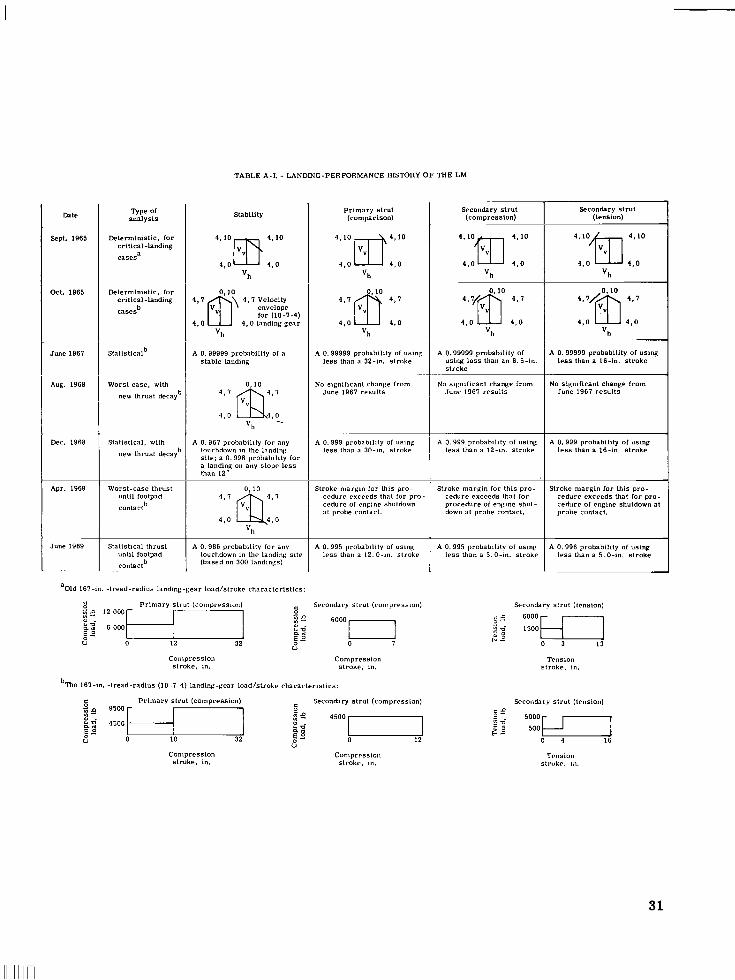
TABLE A-I. ~ LANDING-PERFORMANCE HISTORY O F THE LM
Primary strut (comparison)
Type of analysis
Deterministic, for critical-landing
a cases
Secondary strut (compression)
Secondary strut (tension) Stability m t e
Sept. 1965
Oct. 1965
June 1961
Aug. 1968
Lkc. 1966
Apr. 1969
~
June 1969
'"Om 4 . 0 4 , o 4'10
'h
4 * 1 0 f I l 4 , O 4.0 4'10
'h 4,o 4 , o
'h
4 , o 4 , o 'h
4 , o 4 , o 'h
for (10-7-4) 4 , o 4 , O landing gear
'h
Lkierministic, for critical -landing casesb
Statisticalb A 0,99999 probability of a stable landing
A 0,99999 probability of using less than a 16-in. stroke
No significant change from June 1961 results
A 0,99999 probability of using less than an 6.5-in. stroke
No significant change from June 1961 results
A 0,99999 probabilily of using less than a 32-in. stroke
~~
No significant change from June 1961 results
Worst case, with new thrust decayb 4 , l
4 , o "h .
Statistical, with new thrust decayb
A 0.961 probabtiity for any lourhdown in the landing sile; a 0. 998 probability for a l andiy on any slope less than 12
A 0,999 probability of using less than a 30-in. stroke
A 0.999 probability of using less than a 16-in. stroke
A 0. 999 probability of using less than a 12-in. stroke
Worst-case thrust unt i l footpad contactb
Stroke margin for lhis pro- cedure exre-ds thal for pro- cedure of engine shuldown 31 probe ronlacl .
Stroke margin for this pro- cedure exceeds thal for procedure of engine shut- down at probe conlact.
Stroke margin for this pro- cedure exceeds lhat for pra- cedure of engine shutdown at probe contact.
4 , o 'h
Statistical thrust u n t i l footpad contactb
~
A 0.986 probability for any touchdown in the landing sile (based on 300 landings)
A 0.995 probability of using less than a 12.0-rn. Slroke
A 0,995 probability of using less than a 5.04". stroke
A 0.996 probability of using less than a 5.04". stroke
aOld 161-in. -tread-radius landing-pear load/slroke characteristics
Primary s t r u t (compression) E Secondary slrul (compression)
.$? I.* -1 iz 6O0OI,
U 0 12 32 0 I E O a m
E O U
Secondary strut (tension)
Compression slroke, in.
Compression stroke, in.
b l h e 161-in. -tread-radius ( 1 0 - 1 - 4 ) iandinp-gear ioad/strake rhnracteristrcs:
Primary s t ru t (compression) Secondary s t r u t (compressLon) ;: :q -1 f z 4 5 0 0 7 1 a m
U 0 0 12 2" 10 32 $: U
Compression stroke, in.
Conlprrssioll stroke. 111.
31
REFER EN C ES
A-1. Hilderman, Richard A; Mueller, William H. ; and Mantus, Morton: Landing Dynamics of the Lunar ,Excursion Module. J. Spacecraft Rockets, vol. 3, no. 10, Oct. 1966, pp. 1484-1489.
A-2. Anon. : Landing Dynamics of the Lunar Module (Performance Characteristics). Rept. LED-520-17, Grumman Aircraft Engineering Corp. , June 15, 1967.
A-3. Zupp, George A., Jr. ; hnd Doiron, Harold H. : A Mathematical Procedure for Predicting the Touchdown Dynamics of a Soft-Landing Vehicle. NASA TN D-7045, 1971.
A-4. Anon. : Lunar Module (LM) Soil Mechanics Study. Final Report. Rept. AM-68-1, Energy Controls Division, Bendix Corp., May 1, 1968.
A-5. Anon. : Landing Dynamics of the Lunar Excursion Module (1/6 Scale Model III Test -Analysis Correlation). Rept. LED-520 -12, Grumman Aircraft Engineer - ing Corp., May 16, 1966.
A-6. Blanchard, TJlysse J. : Full-Scale Dynamic Landing-Impact Investigation of a Prototype Lunar Module Landing Gear. NASA TN D-5029, 1969.
A-7. Blanchard, Ulysse J. : Evaluation of a F’ull-Scale Lunar-Gravity Simulator by Comparison of Landing-Impact Tests of a Full-Scale and a 1/6-Scale Model. NASA TN D-4474, 1968.
A-8. Anon. : Landing Dynamics of the Lunar Module (Performance Characteristics Including Descent Engine Thrust Decay Effects). Aircraft Engineering Corp., Apr. 16, 1969.
Rept. LED-520-53, Grumman
32
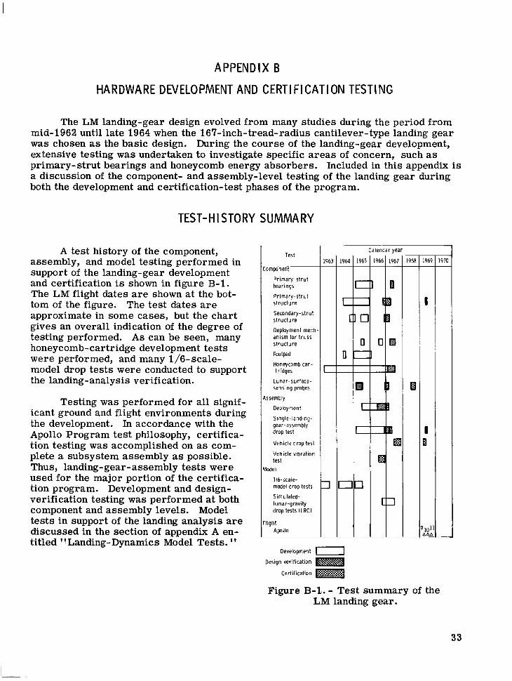
APPENDIX B
HARDWARE DEVELOPMENT AND CERTI FICATI ON TESTING
The LM landing-gear design evolved from many studies during the period from mid-1962 until late 1964 when the 167-inch- tread-radius cantilever-type landing gear w a s chosen as the basic design. During the course of the landing-gear development, extensive testing was undertaken to investigate specific areas of concern, such as primary- strut bearings and honeycomb energy absorbers. Included in this appendix is a discussion of the component- and assembly-level testing of the landing gear during both the development and certification- test phases of the program.
TEST-HISTORY SUMMARY
A test history of the component, assembly, and model testing performed in support of the landing-gear development and certification is shown in figure B-1. The LM flight dates a r e shown at the bot- tom of the figure. The test dates a r e approximate in some cases, but the chart gives an overall indication of the degree of testing performed. A s can be seen, many honeycomb-cartridge development tests were performed, and many 1/6-scale- model drop tests were conducted to support the landing-analysis verification.
Testing was performed for all signif- icant ground and flight environments during the development. In accordance with the Apollo Program test philosophy, certifica- tion testing was accomplished on as com- plete a subsystem assembly as possible. Thus, landing-gear-assembly tests were used for the major portion of the certifica- tion program. Development and design- verification testing was per€ormed at both component and assembly levels. Model tests in support of the landing analysis are discussed in the section of appendix A en- titled "Landing-Dynamics Model Tests. "
Test
Component _____
Primary-strut bearings
Primary-strut structure
Secondary-strut structure
Deployment mech anism for truss structure
Footpad
Honeycomb car- t ridges
Lunar-surface- sensing probes
Assembly
Deployment
Single-landlng- gear-assembly drop lest
Vehicle drop test
Vehicle vibration test
Wdel
116- scale- model drop tests
Simulated- lunar-gravity drop tests ILRC)
Apollo Flight
Development -1 Design verification
Certification
a C
c
717
Calendar year
Figure B-1-. - Test summary of the LM landing gear.
33
DE PLOY MENT TESTS
Extensive landing-gear deployment tests were conducted, beginning with the 160-inch-tread-radius landing-gear design. Tests were conducted in ambient, salt-fog, and thermal-vacuum environments, with the majority conducted under ambient condi- tions. Deployment testing was generally conducted with the landing-gear-assembly axis of deployment in the vertical position; that is, the primary-strut longitudinal axis was perpendicular to the gravity vector. To minimize gravity effects, a cable was attached to the landing gear near its c. g.
Energy requirements for landing-gear deployment were generally determined by testing. Because of the complexity of the landing-gear motions during deployment and because of the difficulty of accurately estimating friction loads at the bearing joints, the deployment energy requirements were only grossly predicted by analysis. Simulated-zero-gravity deployment tests were used as a design tool to verify the deploy- ment energy requirements and to test the deployment- mechanism hardware concepts.
During early deployment testing, much design information was obtained about the 'deployment-mechanism functionality and deployment time. Strut loads were measured to determine the magnitudes of the loads induced by the deployment shock. Honeycomb- cartridge lengths in the secondary strut were measured to determine if any honeycomb crushing occurred as a result of the inertial forces produced by deployment. Loads induced into the LM structure by deployment were measured also. Quantitative data from later tests performed on flight-type hardware consisted primarily of deployment- time information. This information was used to verify that changes to the landing-gear thermal insulation had not adversely affected deployment and to verify the accuracy of the landing-gear checkout tests at the prime contractor facility and at the launch site, The landing-gear -assembly deployment tests (development, design verification, and certification), beginning with initial ground-test hardware and concluding with flight- vehicle checkout and flight-test results, a r e summarized in table B-I. All deployment- test failures and the cause of each failure a r e also summarized. As indicated in table B-I, almost 250 individual landing-gear deployments have been made through the Apollo 11 mission. Detailed information on the development, design-verification, and certification tests may be found in references B-1 to B-9.
Two deployment failures occurred during certification and checkout testing: one during a thermal-vacuum certification test and the other during factory checkout of the Apollo 9 landing gear. The certification-test failure resulted from the use of an im- proper lubricant in the deployment springs during a thermal-vacuum test at a temper- ature of -150" F. In this instance, the landing gear deployed and locked, but not within the specified time. With the correct lubricant on the springs, operation was nominal. The deployment failure on the Apollo 9' landing gear during factory checkout resulted from two deficiencies: ing joint and marginal energy in both deployment springs of the failed landing gear. insulation was redesigned in the vicinity of the deployment joints, the required spring energy was increased, and more rigid acceptance-test requirements were imposed on the deployment-spring assemblies. Component tes ts of the leaf-type deployment spring consisted primarily of functional tests under various environments and of fatigue tests (ref. B-10).
thermal-insulation interference with a deployment- t russ rotat- The
34
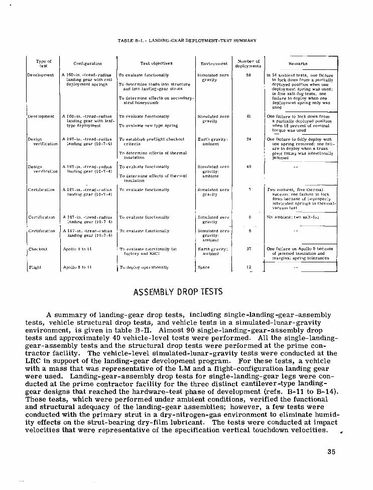
T A B L E B-1. - LANDING-GEAR D E P L O Y M E N T - T E S T SUMMARY
T y p e of t e s t
l e v e l o p m e n t
Development
Design ver i f ica t ion
Des ign ver i f ica t ion
C e r t i f i c a t i o n
c e r t i f i c a t i o n
C e r t i f i c a t i o n
Checkout
F l igh t
Conf igura t ion
\ 160-in. - t r e a d - r a d i u s landing g e a r wi th c o i l deployment s p r i n g s
A 160- in . - t r e a d - r a d i u s landing g e a r wi th l e d - type deployment
A 167-in. - t r e a d - r a d i u s landing g e a r (10-7-4)
A 167-111. - t r e a d - r a d i u s landing g e a r (10-7-4)
A 167-111. - t r e a d - r a d i u s landing g e a r (10-7-4)
A 167- in . - t r e a d - r a d i u s landing g e a r (10-7-4)
A 167- in . - t r e a d - r a d i u s landing g e a r (10-7-4)
Apollo 9 to 11
Apollo 9 to 11
T e s t o b j e c t i v e s
ro e v a l u a t e functionally
To d e t e r m i n e l o a d s into s t r u c t u r e and i n t o landing-gear s t r u t s
To d e t e r m i n e e f f e c t s on s e c o n d a r y - s t r u t honeycomb
To e v a l u a t e func t iona l ly
T o e v a l u a t e new type s p r i n g
T o e s t a b l i s h pref l igh t checkout c r i t e r i a
T o d e t e r m i n e e f f e c t s oi t h e r m a l insu la t ion
T o e v a l u a t e functionally
T o d e t e r m i n e e f f e c t s of t h e r m a l insu la t ion
To e v a l u a t e functionally
T o e v a l u a t e functionally
T o e v a l u a t e functionally
T o e v a l u a t e functionally (a t f a c t o r y and KSC)
T o deploy opera t iona l ly
E n v i r o n m e n t
S imula ted z e r o g r a v i t y
S imula ted z e r o g r a v i t y
E a r t h g r a v i t y : a m b i e n t
S imula ted z e r o g r a v i t y : ambient
S imula ted z e r o g r a v i t y
S imula ted z e r o gravi ty
S imula ted z e r o g r a v i t y : ambient
E a r t h g r a v i t y : ambient
S p a c e
N u m b e r of deployments
59
41
24
49
7
8
.~
6
37
12
R e m a r k s
In 54 ambient t e s t s , o n e f a i l u r e to lock down f r o m a p a r t i a l l y deployed pos i t ion when one deployment s p r i n g w a s u s e d : in f i v e s a l t - f o g t e s t s , one f a i l u r e to deploy when o n e deployment s p r i n g only w a s used
~
One f a i l u r e to lock down f r o m a p a r t i a l l y deployed pos i t ion when 1 6 p e r c e n t of nominal t o r q u e w a s used
One f a i l u r e to ful ly deploy with one s p r i n g r e m o v e d : one f a i l - u r e to deploy when a t r u s s pivot f i t t ing w a s in ten t iona l ly j a m m e d
Two ambient , f ive t h e r m a l - vacuum: one f a i l u r e to lock down b e c a u s e of i m p r o p e r l y lubr ica ted s p r i n g s in t h e r m a l vacuum t e s t . ~~
SIX a m b i e n t ; two sa l t - fop
One f a i l u r e on Apollo 9 b e c a u s e of j a m m e d insu la t ion and m a r g i n a l s p r i n g t o l e r a n c e s
_ _
ASSEMBLY DROP TESTS
A summary of landing-gear drop tests, including single -landing -gear -assembly tests, vehicle structural drop tests, and vehicle tests in a simulated-lunar-gravity environment, is given in table B-II. Almost 90 single-landing-gear-assembly drop tests and approximately 40 vehicle-level tes ts were performed. Al l the single-landing- gear-assembly tests and the structural drop tes ts were performed at the prime con- tractor facility. The vehicle-level simulated-lunar-gravity tes ts were conducted at the LRC in support of the landing-gear development program. For these tests, a vehicle with a mass that was representative of the LM and a flight-configuration landing gear were used. Landing-gear-assembly drop tes ts for single-landing-gear legs were con- ducted at the prime contractor facility for the three distinct cantilever -type landing- gear designs that reached the hardware-test phase of development (refs. B-11 to B-14). These tests, which were performed under ambient conditions, verified the functional and structural adequacy of the landing-gear assemblies; however, a few tests were conducted with the primary s t rut in a dry-nitrogen-gas environment to eliminate humid- ity effects on the strut-bearing dry-film lubricant. The tes ts were conducted at impact velocities that were representative of the specification vertical touchdown velocities. ,
35
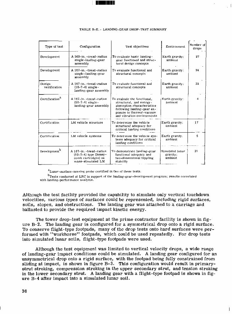
TABLE 8-II. - LANDING-GEAR DROP-TEST SUMMARY
Type of test
Development
Development
Design verification
Certificationa
Certification
Certification
Developmentb
Configuration ~~
A 160-in. - t read-radius single -landing-gear assembly
A 167-in. - t read-radius single -landing-gear assembly
A 167-in. - t read-radius (10-7-4) single- landing-gear assembly
~~
A 167-in. - t read-radius (10-7-4) single- landing-gear assembly
~~ .. . ~
LM vehicle s t ruc ture
LM vehicle sys tems
~ ~~~~
A 167-in. - t read-radius (10-7-4) type (honey- comb car t r idges) on mass-s imulated LM - ~
Test objectives
To evaluate basic landing- gear functional and s t r u c - tu ra l design concepts
To evaluate functional and s t ruc tura l concepts
To evaluate functional and s t ructural concepts
-
To evaluate the functional, s t ructural , and energy- absorption charac te r i s t ics following landing-gear ex- posure to thermal-vacuum and vibration environments
~~ - -.
To determine the vehicle s t ructural adequacy f o r c r i t i ca l landing conditions
To determine the vehicle s y s - t e m s adequacy f o r c r i t i ca l landing conditions
. ~ ..___
~~~ ~ . - ~~~ ~~
ro demonstrate landing-gear functional adequacy and two-dimensional toppling stability
.
Environment
E a r t h gravity: ambient
Ear th gravity: ambient
Earth gravity; ambient
Earth gravity: ambient
3arth gravity: ambient
Zarth gravity; ambient
. - ._____
iimulated lunar gravity: ambient
\lumber o d rops
27
-
24
33
4
- 17
5
21
aLunar-surface-sensing probe certified in two of these tes ts .
bTests conducted at LRC in support of the landing-gear-development program; resu l t s correlated with landing-performance analysis.
Although the test facility provided the capability to simulate only vertical touchdown velocities, various types of surfaces could be represented, including rigid surfaces, soils, slopes, and obstructions. The landing gear was attached to a carriage and ballasted to provide the required impact kinetic energy.
The tower drop-test equipment at the prime contractor.facility is shown in fig- ure B-2. The landing gear is configured for a symmetrical drop onto a rigid surface. To conserve flight-type footpads, many of the drop tests onto hard surfaces were per- formed with "workhorse" footpads, which could be used repeatedly. For drop tests into simulated lunar soils, flight-type footpads were used.
Although the test equipment was limited to vertical velocity drops, a wide range of landing-gear impact conditions could be simulated. A landing gear configured for an unsymmetrical drop onto a rigid surface, with the footpad being fully constrained from sliding at impact, is shown in figure B-3. This configuration would result in primary- s t rut stroking, compression stroking in the upper secondary strut, and tension stroking in the lower secondary strut. A landing gear with a flight-type footpad is shown in fig- u re B-4 after impact into a simulated lunar soil.
36
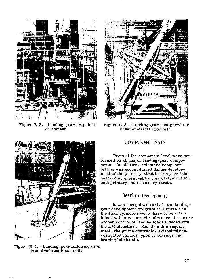
Figure B-2. - Landing-gear drop-test equipment.
Figure B-3. - Landing gear configured for unsymmetrical drop test.
COMPONENT TESTS
Tests at the component level were per- formed on all major landing-gear compo- nents. In addition, extensive component testing was accomplished during develop- ment of the primary-strut bearings and the honeycomb energy-absorbing cartridges for both primary and secondary struts.
Bea r i ng D eve I opm en t
It was recognized early in the landing- gear development program that friction in the strut cylinders would have to be main- tained within reasonable tolerances to ensure proper control of landing loads induced into the LM structure. Based on this require- ment, the prime contractor extensively in- vestigated various types of bearings and bearing lubricants.
Figure B-4. - Landing gear following drop into simulated lunar soil.
37
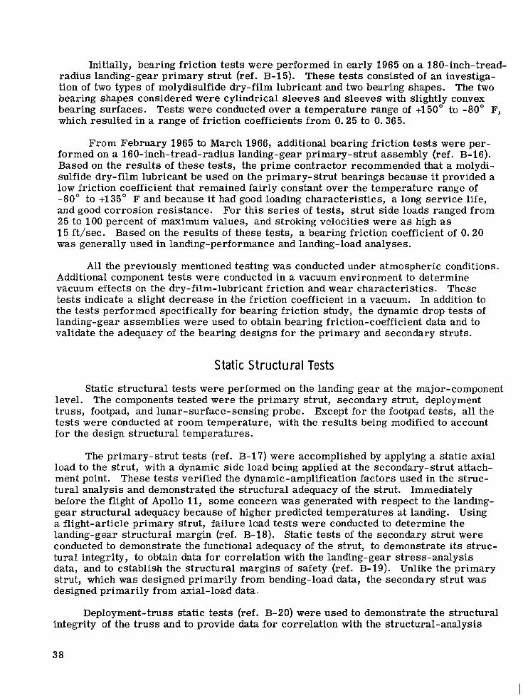
Initially, bearing friction tests were performed in early 1965 on a 180-inch-tread- radius landing-gear primary s t rut (ref. B-15). These tests consisted of an investiga- tion of two types of molydisulfide dry-film lubricant and two bearing shapes. The two bearing shapes considered were cylindrical sleeves and sleeves with slightly convex bearing surfaces. Tests were conducted over a temperature range of +150° to -80" F, which resulted in a range of friction coefficients from 0.25 to 0.365.
From February 1965 to March 1966, additional bearing friction tests were per- formed on a 160-inch-tread-radius landing-gear primary-strut assembly (ref. B-16). Based on the results of these tests, the prime contractor recommended that a molydi- sulfide dry-film lubricant be used on the primary-strut bearings because it provided a low friction coefficient that remained fairly constant over the temperature range of -80" to +135" F and because it had good loading characteristics, a long service life, and good corrosion resistance. 25 to 100 percent of maximum values, and stroking velocities were as high as 15 ft/sec. Based on the results of these tests, a bearing friction coefficient of 0.20 was generally used in landing-performance and landing-load analyses.
For this se r ies of tests, strut side loads ranged from
Al l the previously mentioned testing was conducted under atmospheric conditions. Additional component tests were conducted in a vacuum environment to determine vacuum effects on the dry-film-lubricant friction and wear characteristics. These tests indicate a slight decrease in the friction coefficient in a vacuum. In addition to the tests performed specifically for bearing friction study, the dynamic drop tests of landing-gear assemblies were used to obtain-bearing friction-coefficient data and to validate the adequacy of the bearing designs for the primary and secondary struts.
Static Structural Tests
Static structural tests were performed on the landing gear at the major-component level. The components tested were the primary strut, secondary strut, deployment truss, footpad, and lunar-surface-sensing probe. Except for the footpad tests, all the tests were conducted at room temperature, with the results being modified to account for the design structural temperatures.
The primary-strut tes ts (ref. B-17) were accomplished by applying a static axial load to the strut, with a dynamic side load being applied at the secondary-strut attach- ment point. These tests verified the dynamic-amplification factors used in the struc- tural analysis and demonstrated the structural adequacy of the strut. Immediately before the flight of Apollo 11, some concern was generated with respect to the landing- gear structural adequacy because of higher predicted temperatures at landing. Using a flight-article primary strut, failure load tes ts were conducted to determine the landing-gear structural margin (ref. B-18). Static tests of the secondary strut were conducted to demonstrate the functional adequacy of the strut, to demonstrate its struc- tural integrity, to obtain data for correlation with the landing-gear stress-analysis data, and to establish the structural margins of safety (ref. B-19). Unlike the primary strut, which was designed primarily from bending-load data, the secondary strut was designed primarily from axial-load data.
Deployment-truss static tests (ref. B-20) were used to demonstrate the structural integrity of the t russ and to provide data for correlation with the structural-analysis
data. All components of the t ru s s were subjected to failure loads. tests of the trunnion fitting that attaches the deployment t russ to the descent-stage structure also were conducted (ref. B-21).
Static ultimate-load
Footpad-Com ponen t Tests
Component tests of various footpad configurations began early in the landing- gear
Because of the unknown characteristics of the landing site, a footpad that could Furthermore, the footpad
2 test program. The footpad was required to sustain a 12-lb/in normal-pressure load- ing. sustain crushing against various obstacles was required. should plane adequately while sliding over the lunar surface because of a horizontal velocity component at touchdown. sibility of the footpad digging into the lunar soil and being ripped away from the pri- mary strut.
This specification was required to preclude the pos-
The footpad component-level tests demonstrated the strength of the footpad when subjected to a uniformly distributed normal load and evaluated the load/stroke charac- terist ics of the footpad when laterally crushed against obstacles of various shapes. Normal-load component tests were conducted at room temperature and at 225" F. footpad was tested dynamically during the landing-gear-assembly drop tests. crushing tests were conducted at various load rates and with a variety of obstacle shapes. Lateral crushing of flight- type footpads was also investigated during landing- gear-assembly drop tes ts onto hard surfaces. Details of the footpad-component tests a r e contained in references B-22 to B-25.
The Side-load
Honeycomb Energy Absorber
The choice of a method for absorbing the LM impact energy at touchdown is based
The energy absorber must have on several requirements. ing, the energy absorber does not have to be recycled. load/stroke characteristics that a r e predictable, within close limits, in order to con- trol the loads induced into the vehicle structure. Light weight, compatibility with the space environment, and simplicity a r e other desirable features. Early in the LM development program, various devices were evaluated in the search for an energy absorber that met these requirements. Initial investigations by the prime contractor indicated that crushable honeycomb could fulfill the requirements and could be developed within the constraints of the Apollo Program schedule.
Because the landing gear is required for only a single land-
It became evident early in the honeycomb-development program that several fac- to rs influence the load level at which honeycomb crushes. The primary factors are manufacturing tolerances, temperature, and impact velocity. that have a significant effect on the strength of the honeycomb are the expansion of the hobe (the basic block of alternate layers of aluminum foil and adhesive that is expanded to form the honeycomb core), the foil thickness, the foil material properties, and the adhesive application and curing method. Honeycomb temperature also has a significant effect on the crush strength, with the crush strength decreasing as temperature in- creases. The crush-load level for an impact velocity is approximately 10 percent greater than the static crush-load level, and this increment is approximately constant over a range of 3 to 12 ft/sec.
Manufacturing tolerances
39
These effects were investigated extensively by the prime contractor during devel- opment of honeycomb cartridges that were suitable for use on the landing gear. Manu- facturing tolerances were reduced to approximately i 2 percent for the final flight-type cartridges. Velocity effects were accounted for in sizing the cartridges, and tempera- ture effects were reduced to acceptable levels by providing thermal insulation on the landing- gear struts.
The variations in the crush-load levels have been considered in the LM structural- load and landing-performance analyses. In the landing-performance studies, an ex- tensive analysis of the effects of cartridge temperature on vehicle stability and energy-absorption requirements was performed. Honeycomb-development and design- verification- test results are contained in references B-26 to B-30.
LUNAR-SURFACE-SENS ING-PROBE QUAL1 FICATION TESTS
During the course of hardware development, two distinct sensing probes were used in flight. A 4. &foot probe was used on the Apollo 9 and 10 missions, and a 5.6-foot probe was used on the Apollo 11 mission. Both probe designs underwent com- plete qualification-test programs. Details of the qualification of the 5.6-foot probe a r e contained in reference B-31. With the exception of probe certification in drop tests, certification was accomplished by the probe-hardware vendor.
Two probe assemblies were subjected to all significant mission-level environ- ments, including shock, vibration, and thermal-vacuum environments. The electro- mechanical sensing- switch operation was monitored during testing, and the probe-deployment mechanism was checked. Before qualification of the early model 4.5-fOOt probe, extensive development testing was performed by the vendor under the cognizance of the prime contractor.
CERTI F I CAT1 ON SUMMARY
All certification-level tes ts a r e listed in table B-III. Also provided is a brief description of the tests, information about the level of assembly, and whether the test was an original requirement or was added because of a design change o r a new qualifi- cation requirement. The flight hardware is compared with the certified hardware in table B-IV. Some design changes did not necessitate complete hardware recertifica- tion for various reasons. These design changes, together with the reasons the flight configuration was considered to be adequate, a r e a lso listed in table B-IV. Where practical, analysis was performed to demonstrate the adequacy of the flight hardware; however, in some cases, configuration differences were so minor that the flight hard- ware was determined to be adequate by design similarity.
40
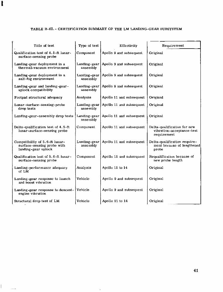
TABLE B-III. - CERTIFICATION SUMMARY OF THE LM LANDING-GEAR SUBSYSTEM
Title of test
Qualification test of 4.5-ft lunar- surface-sensing probe
Landing-gear deployment in a thermal-vacuum environment
Landing-gear deployment in a salt-fog environment
Landing-gear and landing-gear- uplock compatibility
Footpad structural adequacy
Lunar -surface -sensing-probe drop tests
Landing-gear-assembly drop tests
Delta-qualification test of 4.5-ft lunar-surface-sensing probe
Compatibility of 5.6-ft lunar- surface-sensing probe with landing - gear uploc k
Qualification test of 5.6-ft lunar- surface-sensing probe
Landing-performance adequacy of LM
Landing-gear response to launch and boost vibration
Landing-gear response to descent- engine vibration
Structural drop test of LM
Type of test
Component
Landing-gear assembly
Landing-gear assembly
Landing-ge ar assembly
Analysis
Landing - ge ar assembly
Landing-gear assembly
Component
Landing-gear assembly
Component
Analysis
Vehicle
Vehicle
Vehicle
Effectivity
Apollo 9 and subsequent
Apollo 9 and subsequent
Apollo 9 and subsequent
Apollo 9 and subsequent
Apollo 11 and subsequent
Apollo 11 and subsequent
Apollo 11 and subsequent
Apollo 11 and subsequent
Apollo 11 and subsequent
Apollo 11 and subsequent
Apollo 11 to 14
Apollo 9 and subsequent
Apollo 9 and subsequent
Apollo 11 to 14
Requirement
Original
Original
Original
Original
Original
Original
Delta-qualification for new vibration-acceptance-test requirement
Delta-qualification require- ment because of lengthenet probe
Requalification because of new probe length
Original
Original
Original
Original
4 1
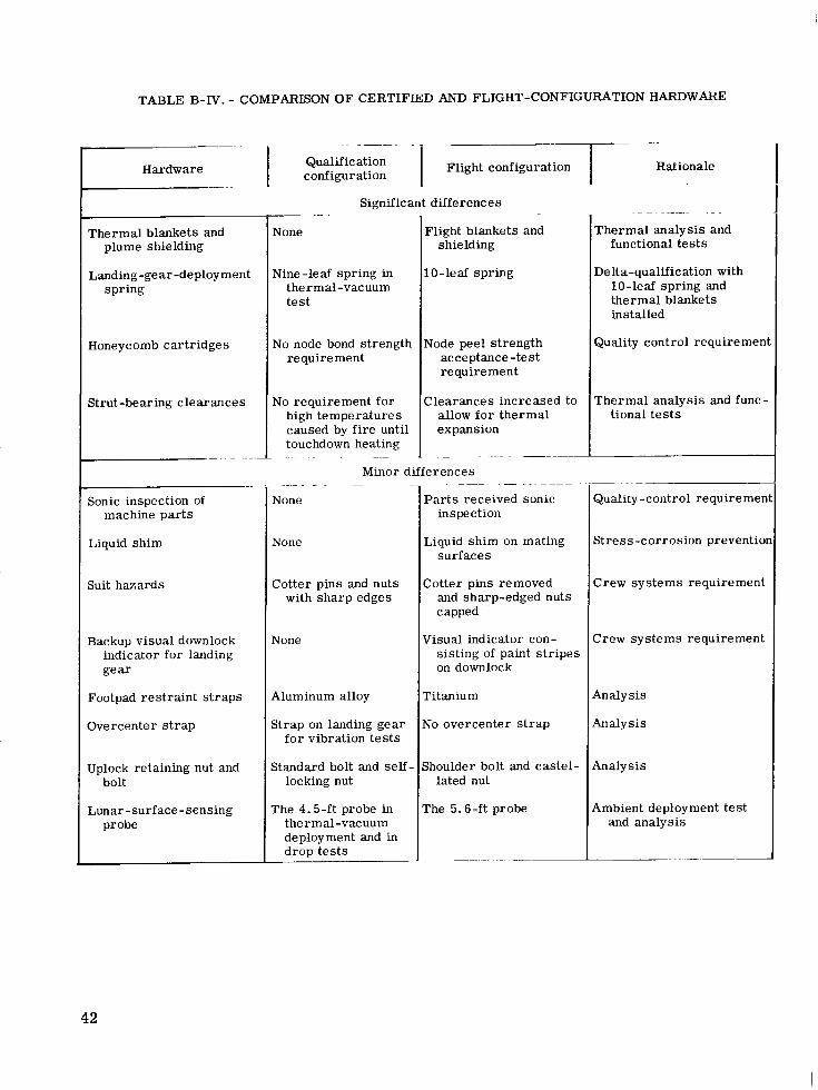
TABLE B-IV. - COMPARISON O F CERTIFIED AND FLIGHT-CONFIGURATION HARDWARE
Hardware
Thermal blankets and plume shielding
Landing-gear -deployment spring
Honeycomb cartridges
Strut-bearing clearances
Sonic inspection of machine par t s
Liquid shim
Suit hazards
Backup visual downlock indicator for landing gear
Footpad restraint s t raps
Overcenter s t r ap
Uplock retaining nut and bolt
Lunar -surf ace - sensing probe
Flight configuration Qualification configuration
Significant differences .
None
Nine-leaf spring in therm a1 -vac uum test
No node bond strength requirement
No requirement for high temperatures caused by fire until touchdown heating
~ - _ ..
plight blankets and shielding
0-leaf spring
Jode peel strength acceptance -test requirement
:learances increased to allow fo r thermal expansion
Minor differences -. -
None
None
Cotter pins and nuts with sharp edges
None
Aluminum alloy
Strap on landing gear for vibration tes t s
Standard bolt and self locking nut
The 4.5-ft probe in thermal-vacuum deployment and in drop tes t s
P a r t s received sonic inspect ion
Liquid shim on mating surfaces
Cotter pins removed and sharp-edged nuts capped
Visual indicator con- sisting of paint s t r ipes on downlock
Titanium
No overcenter s t r ap
Shoulder bolt and castel- lated nut
The 5.6-ft probe
Rat ionale
- . .
Thermal analysis and functional tests
Delta-qualification with 10-leaf spring and thermal blankets installed
Quality control requireme
Thermal analysis and func tional tes t s
Quality -control requireme
Stress-corrosion preventi
Crew systems requiremen
Crew systems requiremen
Analysis
Analysis
Analysis
Ambient deployment tes t and analysis
42
REFERENCES
B-1. Anon. : Test Results for Landing Gear Assembly Tests, Section B - Results of the 160" Landing Gear Deployment Tests. Rept. LTR 904-14001B, Grumman Aircraft Engineering Corp., Jan. 21, 1966.
B-2. Anon. : Test Results for the Landing Gear Assembly Tests, Section C - Results of the 160" Landing Gear Deployment Tests After Salt Fog. Rept. LTR 904-14001C, Grumman Aircraft Engineering Corp., May 25, 1966.
B-3. Anon. : Results of the 167" Semi-Tread (10-7-4) Landing Gear Vertical Deploy- ment Tests. Rept. LTR 904-14005, Grumman Aircraft Engineering Corp., Feb. 2, 1967.
B-4. Anon. : Results of Thermal Vacuum Test of 167" Semi- Tread (10-7-4) Landing Gear Assembly. Rept. LTR 904-14012, Grumman Aircraft Engineering Corp., Mar. 13, 1967.
B-5. Anon. : Results of the Deployment Tests (Horizontal) of the 167" Semi-Tread (10-7-4) Landing Gear Assembly. Rept. LTR 904-14020, Grumman Aircraft Engineering Corp., Apr. 6, 1967.
B-6. Anon. : Results of 167" (10-7-4) Landing Gear Vertical Deployment Tests Using Full Insulation. Rept. LTC 904-14024, Grumman Aircraft Engineering Corp. , Sept. 18, 1967.
B-7. Anon. : Results of Landing Gear Deployment Tests (With Revised Insulation Con- figuration). Rept. LTR 904-14036, Grumman Aircra€t Engineering Corp. , June 20, 1969.
B-8. Anon. : Results of the 167" (10-7-4) Landing Gear Deployment Tests With the Revised Thermal Insulation. Rept. LTC 904-1 5008, Grumman Aircraft Engineering Corp., Aug. 8, 1969.
B-9. Anon. : Test Results of the Certification Test of the LM Landing Gear Deploy- ment System Equipped With Environmental Protective Covers. Rept. LTR 904-14014, Grumman Aircraft Engineering Corp., Feb. 27, 1967.
B-10. Anon. : Test Results of the LM Landing Gear Component Development Test. Results of the Component Tests of the LM Landing Gear Deployment Spring LSC320-202. Rept. LTC 904-14016, Grumman Aircraft Engineering Corp., Feb. 15, 1967.
B-11. Anon. : Test Results fo r Landing Gear Assembly Tests, Section A - Test Results for 160" Semi-Tread Landing Gear Assembly Tests. Rept. LTR 904-14001B, Grumman Aircraft Engineering Corp., Sept. 15, 1966.
43
B-12. Anon. : Test Results for Landing Gear Assembly Tests, Section E - Test Results for 167" Semi-Tread Landing Gear Assembly Tests. Rept. LTR 904-14001D, Grumman Aircraft Engineering Corp., June 9, 1967.
B-13. Anon. : Results of the LM 167 Inch Semi-Tread (10-7-4) Landing Gear Assem- bly Drop Test Program. Rept. LTR 904-14009, Grumman Aircraft Engineer- ing Corp., Oct. 12, 1967.
B-14. Anon. : Results of Drop Tests for Certification of LM 167 Inch Semi-Tread (1 0-7-4) Landing Gear Assembly. Rept. LTR 904-14013, Grumman Aircraft Engineering Corp., Aug. 25, 1967.
B-15. Anon. : Test Report for the Development of Linear Bearing Friction Materials Rept. LTR 320-5, Grumman Aircraft Engineering Corp., 180" Strut.
Mar. 16, 1966.
B-16. Anon. : Test Report for the Cantilever Pr imary Strut Assembly Friction Load Test 160" Strut. Rept. LTR 320-6, Grumman Aircraft Engineering Corp., Apr. 15, 1966.
B-17. Anon. : Results of the Structural Tests of the 167" (10-7-4) Landing Gear Pri- mary Strut. Rept. LTR 904-14003, Grumman Aircraft Engineering Corp., Sept. 18, 1967.
B-18. Anon. : Results of the Primary Strut Failing Load Test. Rept. LTR 904-14035, Grumman Aircraft Engineering Corp., June 18, 1969.
B-19. Anon. : Results of Functional and Structural Tests of LDW 320-23553 Secondary Strut Assembly and (10-7-4) Ball Joint Assembly. Rept. LTR 904-14004, Grumman Aircraft Engineering Corp., Sept. 30, 1967.
B-20. Anon. : Results of Structural Tests of the 167" (10-7-4) Landing Gear Deploy- ment Truss. Rept. LTR 904-14007, Grumman Aircraft Engineering Corp., July 19, 1967.
B-21. Anon. : Report of Landing Gear Trunnion Failing Load Investigation. Rept. LTR 904-14034, Grumman Aircraft Engineering Corp., June 17, 1969.
B-22. Anon. : Results of the LEM Landing Gear Component Development Tests, Section D - Results of the Static Test of the LEM Landing Gear Footpad LSK-320-10702. Rept. LTR 904-10001D, Grumman Aircraft Engineering Corp., Feb. 14, 1966.
B-23. Anon. : Results of the LEM Landing Gear Component Development Tests, Section J - Results of the Static Test of the LEM Landing Gear Footpad LSK-320-10704. Rept. LTR 904-10001. Grumman Aircraft Engineering Corp., Feb. 28, 1966.
44
Ill I I I II 1111 I 1 1 ~ 1 1 1 I I I l l I I
B-24. Anon. : Results of the LEM Landing Gear Component Development Tests, Section M - Results of the Static Test of the LEM Landing Gear Footpad LSK-320-10707. Corp., Feb. 12, 1966.
Rept. LTR 904-10001, Grumman Aircraft Engineering
B-25. Anon. : Results of the LEM Landing Gear Component Development Tests, Section Q - Results of the Normal Load Test of Footpad LTM-320-H-10701. Rept. LTR 904-10001, Grumman Aircraft Engineering Corp., Aug. 9, 1966.
B-26. Anon. : Design Data Derived From Preliminary Testing of Honeycomb Car- tridge. Rept. LTR 320-4, Grumman Aircraft Engineering Corp. , Jan. 14, 1966.
B-27. Anon. : Results of the LEM Landing Gear Component Development Tests, Section B - Crushable Cartridges - Intermediate and Full Size. Rept. LTR 904-10001, Grumman Aircraft Engineering Corp. , Jan. 6, 1967.
B-28. Anon. : Results of the LEM Landing Gear Component Development Tests, Section P - Crushable Honeycomb Cartridges for the 160" and 167" Landing Gear Assemblies. Rept. LTR 904-1 0001, Grumman Aircraft Engineering Corp., Apr. 5, 1967.
B-29. Anon. : Results of Tests on the 167" (10-7-4) Landing Gear Honeycomb Car- tridges - Block I. Rept. LTR 904-14010, Grumman Aircraft Engineering Corp., June 16, 1967.
B-30. Anon. : Design Data Derived From the Intermediate Testing of Honeycomb Cartridges. Rept. LTR 320-13, Grumman Aircraft Engineering Corp. , Aug. 18, 1967.
B-31. Anon. : Final Report - Qualification Test of the 5 .6 Foot Lunar Surface Sensing Probe for LM. Rept. 8342, rev. A, Edo Corp. , Mar. 1969.
45
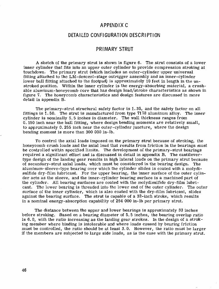
APPENDIX C
D ETA LED CONFIGURATION DESCR
PRIMARY STRUT
PTION
A sketch of the primary strut is shown in figure 6. The strut consists of a lower inner cylinder that fits into an upper outer cylinder to provide compression stroking at touchdown. The primary strut (which includes an outer-cylinder upper universal fitting attached to the LM-descent- stage outrigger assembly and an inner-cylinder lower ball fitting attached to the footpad) is approximately 10 feet in length in the un- stroked position. Within the inner cylinder is the energy-absorbing material, a crush- able aluminum-honeycomb core that has design load/stroke characteristics as shown in figure 7. The honeycomb characteristics and design features a r e discussed in more detail in appendix El.
The primary-strut structural safety factor is 1.35, and the safety factor on all fittings is 1.50. The strut is manufactured from type 7178 aluminum alloy. The inner cylinder is nominally 5.5 inches in diameter. The wall thickness ranges from 0. 150 inch near the ball fitting, where design bending moments a r e relatively small, to approximately 0.255 inch near the outer-cylinder juncture, where the design bending moment is more than 300 000 in-lb.
To control the axial loads imposed on the primary strut because of stroking, the honeycomb crush loads and the axial load that results from friction in the bearings must be controlled within specified limits. The development of the primary- strut bearings required a significant effort and is discussed in detail in appendix B. The cantilever- type design of the landing gear results in high lateral loads on the primary strut because of secondary-strut axial loads, which must be considered in the bearing design. The aluminum-sleeve-type bearing over which the cylinder slides is coated with a molydi- sulfide dry-film lubricant. For the upper bearing, the inner surface of the outer cylin- der acts as the sleeve, and the inner-cylinder bearing surface is a machined part of the cylinder. All bearing surfaces a r e coated with the molydisulfide dry-film lubri- cant. The lower bearing is threaded into the lower end of the outer cylinder. The outer surface of the inner cylinder, which is also coated with the dry-film lubricant, slides against the bearing surface. in a nominal energy-absorption capability of 254 000 in-lb per primary strut.
The strut is capable of a 32-inch stroke, which results
The distance between the upper and lower bearings is approximately 33 inches before stroking. Based on a bearing diameter of 5.5 inches, the bearing overlap ratio is 6.0, with the ratio increasing as the landing gear strokes. In the design of a strok- ing member where binding is intolerable and where loads caused by bearing friction must be controlled, the ratio should be at least 3.0. However, the ratio must be larger if the members a r e subjected to large side loads, as is the case with the primary strut.
46
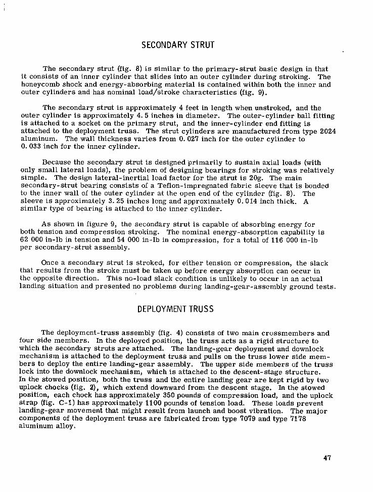
SECONDARY STRUT
The secondary strut (fig. 8) is similar to the primary-strut basic design in that it consists of an inner cylinder that slides into an outer cylinder during stroking. The honeycomb shock and energy-absorbing material is contained within both the inner and outer cylinders and has nominal load/stroke characteristics (fig. 9).
The secondary strut is approximately 4 feet in length when unstroked, and the outer cylinder is approximately 4. 5 inches in diameter. The outer-cylinder ball fitting is attached to a socket on the primary strut, and the inner-cylinder end fitting is attached to the deployment truss. The strut cylinders a r e manufactured from type 2024 aluminum. The wall thickness varies from 0.027 inch for the outer cylinder to 0.033 inch for the inner cylinder.
Because the secondary strut is designed primarily to sustain axial loads (with only small lateral loads), the problem of designing bearings for stroking was relatively simple. The design lateral-inertial load factor for the strut is 20g. The main secondary- strut bearing consists of a Teflon-impregnated fabric sleeve that is bonded to the inner wall of the outer cylinder a t the open end of the cylinder (fig. 8). The sleeve is approximately 3.25 inches long and approximately 0.014 inch thick. A similar type of bearing is attached to the inner cylinder.
A s shown in figure 9, the secondary strut is capable of absorbing energy for both tension and compression stroking. The nominal energy-absorption capability is 62 000 in-lb in tension and 54 000 in-lb in compression, for a total of 116 000 in-lb per secondary-strut assembly.
Once a secondary strut is stroked, for either tension o r compression, the slack that results from the stroke must be taken up before energy absorption can occur in the opposite direction. This no-load slack condition is unlikely to occur in an actual landing situation and presented no problems during landing-gear-assembly ground tests.
DEPLOYMENT TRUSS
The deployment-truss assembly (fig. 4) consists of two main crossmembers and four side members. In the deployed position, the t russ acts as a rigid structure to which the secondary s t ruts a r e attached. The landing- gear deployment and downlock mechanism is attached to the deployment t russ and pulls on the t russ lower side mem- bers to deploy the entire landing-gear assembly. The upper side members of the t russ lock into the downlock mechanism, which is attached to the descent-stage structure. In the stowed position, both the t russ and the entire landing gear are kept rigid by two uplock chocks (fig. 2), which extend downward from the descent stage. In the stowed position, each chock has approximately 350 pounds of compression load, and the uplock strap (fig. C-1) has approximately 1100 pounds of tension load. These loads prevent landing-gear movement that might result from launch and boost vibration. The major components of the deployment t russ are fabricated from type 7079 and type 7178 aluminum alloy.
47
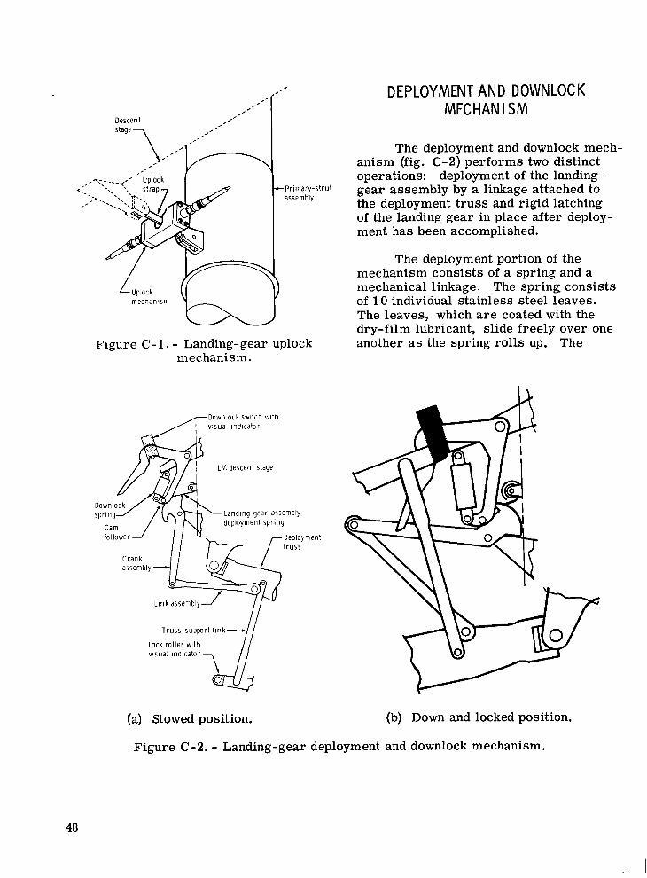
DEPLOYMENT AND DOWNLOCK MECHANISM
Descent
The deployment and downlock mech- anism (fig. C-2) performs two distinct operations: deployment of the landing- gear assembly by a linkage attached to the deployment t russ and rigid latching of the landing gear in place after deploy- ment has been accomplished.
Pr imary-s t ru t assembly
The deployment portion of the mechanism consists of a spring and a mechanical linkage. The spring consists of 10 individual stainless steel leaves. The leaves, which a r e coated with the dry-film lubricant, slide freely over one another as the spring rolls up. The Figure C-1. - Landing-gear uplock
mechanism .
/Downlock switch wi th visual indicator
LM descent stage
Landing-gear- assembly
Deployment t russ
Truss-support l i n k
visual indicator, lock ro l ler wi th
(a) Stowed position. (b) Down and locked position.
Figure C-2. - Landing-gear deployment and downlock mechanism.
48
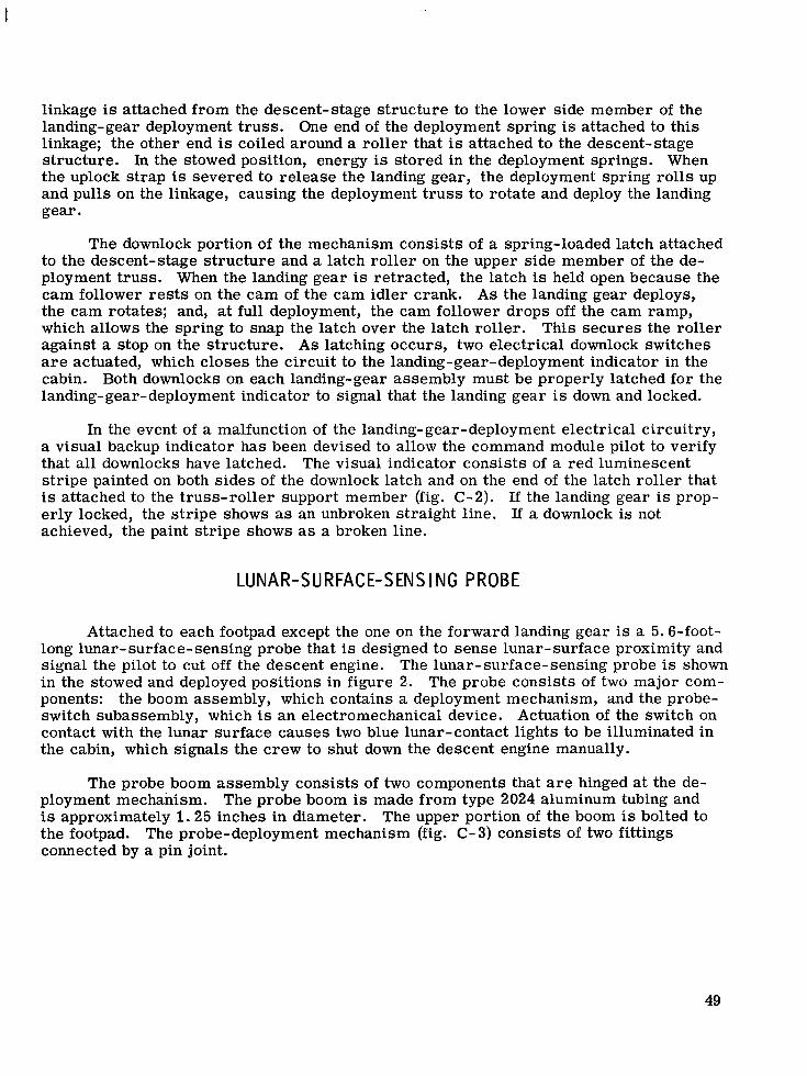
I
linkage is attached from the descent-stage structure to the lower side member of the landing-gear deployment truss. One end of the deployment spring is attached to this linkage; the other end is coiled around a roller that is attached to the descent-stage structure. In the stowed position, energy is stored in the deployment springs. When the uplock strap is severed to release the landing gear, the deployment spring rolls up and pulls on the linkage, causing the deployment t russ to rotate and deploy the landing gear.
The downlock portion of the mechanism consists of a spring-loaded latch attached to the descent-stage structure and a latch roller on the upper side member of the de- ployment truss. When the landing gear is retracted, the latch is held open because the cam follower r e s t s on the cam of the cam idler crank. A s the landing gear deploys, the cam rotates; and, at full deployment, the cam follower drops off the cam ramp, which allows the spring to snap the latch over the latch roller. This secures the roller against a stop on the structure. A s latching occurs, two electrical downlock switches a r e actuated, which closes the circuit to the landing-gear-deployment indicator in the cabin. Both downlocks on each landing-gear assembly must be properly latched for the landing-gear-deployment indicator to signal that the landing gear is down and locked.
In the event of a malfunction of the landing-gear-deployment electrical circuitry, a visual backup indicator has been devised to allow the command module pilot to verify that all downlocks have latched. The visual indicator consists of a red luminescent stripe painted on both sides of the downlock latch and on the end of the latch roller that is attached to the truss-roller support member (fig. C-2). If the landing gear is prop- erly locked, the stripe shows as an unbroken straight line. If a downlock is not achieved, the paint stripe shows as a broken line.
LUNAR-SURFACE-SENSING PROBE
Attached to each footpad except the one on the forward landing gear is a 5.6-foot- long lunar- surface- sensing probe that is designed to sense lunar- surface proximity and signal the pilot to cut off the descent engine. The lunar-surface-sensing probe is shown in the stowed and deployed positions in figure 2. The probe consists of two major com- ponents: the boom assembly, which contains a deployment mechanism, and the probe- switch subassembly, which is an electromechanical device. Actuation of the switch on contact with the lunar surface causes two blue lunar-contact lights to be illuminated in the cabin, which signals the crew to shut down the descent engine manually.
The probe boom assembly consists of two components that a r e hinged at the de-
The upper portion of the boom is bolted to ployment mechanism. The probe boom is made from type 2024 aluminum tubing and is approximately 1.25 inches in diameter. the footpad. The probe-deployment mechanism (fig. C- 3) consists of two fittings connected by a pin joint.
49
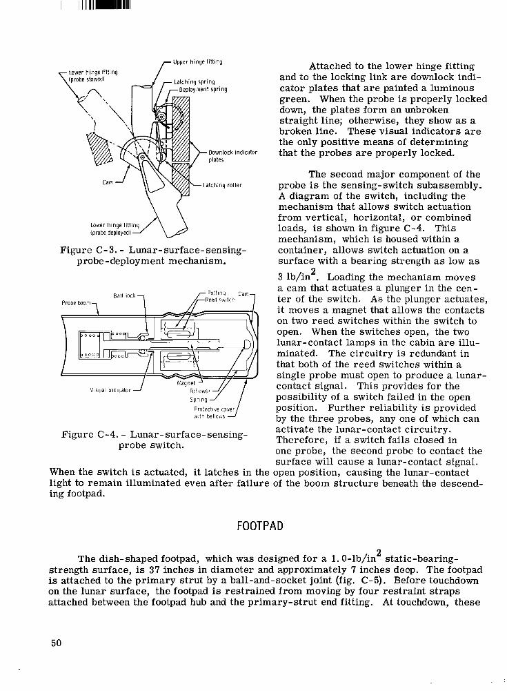
Upper hinge fitting
Figure C-3. - Lunar-surface-sensing- probe -deployment mechanism.
Ball lock 7 Probe boom-,
Visual indicator 1 Spring
with be1lov.s
Figure C-4. - Lunar-surface-sensing- probe switch.
Attached to the lower hinge fitting and to the locking link a r e downlock indi- cator plates that a r e painted a luminous green. When the probe is properly locked down, the plates form an unbroken straight line; otherwise, they show as a broken line. These visual indicators are the only positive means of determining that the probes are properly locked.
The second major component of the probe is the sensing- switch subassembly. A diagram of the switch, including the mechanism that allows switch actuation from vertical, horizontal, o r combined loads, is shown in figure C-4. This mechanism, which is housed within a container, allows switch actuation on a surface with a bearing strength as low as
2 3 lb/in . Loading the mechanism moves a cam that actuates a plunger in the cen- te r of the switch. A s the plunger actuates, it moves a magnet that allows the contacts on two reed switches within the switch to open. When the switches open, the two lunar-contact lamps in the cabin a r e illu- minated. The circuitry is redundant in that both of the reed switches within a single probe must open to produce a lunar- contact signal. This provides for the possibility of a switch failed in the open position. Further reliability is provided by the three probes, any one of which can activate the lunar- contac t circuitry. Therefore, if a switch fails closed in one probe, the second probe to contact the surface will cause a lunar-contact signal.
When the switch is actuated, it latches in the open position, causing the lunar-contact light to remain illuminated even after failure of the boom structure beneath the descend- ing footpad.
FOOTPAD
2 The dish-shaped footpad, which was designed for a 1. 0-lb/in static-bearing- strength surface, is 37 inches in diameter and approximately 7 inches deep. The footpad is attached to the primary strut by a ball-and-socket joint (fig. C-5). Before touchdown on the lunar surface, the footpad is restrained from moving by four restraint s t raps attached between the footpad hub and the primary-strut end fitting. At touchdown, these
50
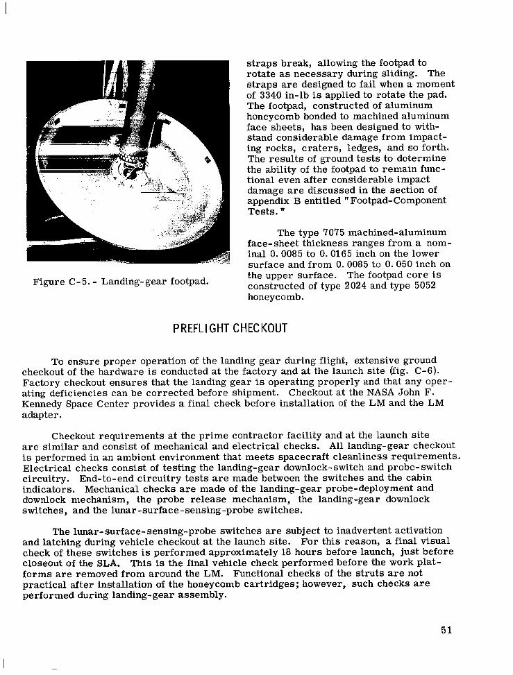
Figure C-5. - Landing-gear footpad.
s t raps break, allowing the footpad to rotate as necessary during sliding. The s t raps are designed to fail when a moment of 3340 in-lb is applied to rotate the pad. The footpad, constructed of aluminum honeycomb bonded to machined aluminum face sheets, has been designed to with- stand considerable damage from impact- ing rocks, craters , ledges, and so forth. The results of ground tests to determine the ability of the footpad to remain func- tional even after considerable impact damage a r e discussed in the section of appendix B entitled " Footpad-Component Tests. "
The type 7075 machined-aluminum face-sheet thickness ranges from a nom- inal 0.0085 to 0.0165 inch on the lower surface and from 0.0085 to 0.050 inch on the upper surface. The footpad core is constructed of type 2024 and type 5052 honeycomb.
PREFLIGHT CHECKOUT
To ensure proper operation of the landing gear during flight, extensive ground checkout of the hardware is conducted at the factory and at the launch site (fig. C-6). Factory checkout ensures that the landing gear is operating properly and that any oper- ating deficiencies can be corrected before shipment. Kennedy Space Center provides a final check before installation of the LM and the LM adapter.
Checkout at the NASA John F.
Checkout requirements at the prime contractor facility and at the launch site a r e similar and consist of mechanical and electrical checks. All landing-gear checkout is performed in an ambient environment that meets spacecraft cleanliness requirements. Electrical checks consist of testing the landing-gear downlock-switch and probe- switch circuitry. End-to-end circuitry tests a r e made between the switches and the cabin indicators. Mechanical checks a r e made of the landing-gear probe-deployment and downlock mechanism, the probe release mechanism, the landing-gear downlock switches, and the lunar -surface-sensing-probe switches.
The lunar-surface- sensing-probe switches are subject to inadvertent activation and latching during vehicle checkout at the launch site. check of these switches is performed approximately 18 hours before launch, just before closeout of the SLA. forms a r e removed from around the LM. practical after installation of the honeycomb cartridges ; however, such checks a r e performed during landing-gear assembly.
For this reason, a final visual
This is the final vehicle check performed before the work plat- Functional checks of the struts are not
51
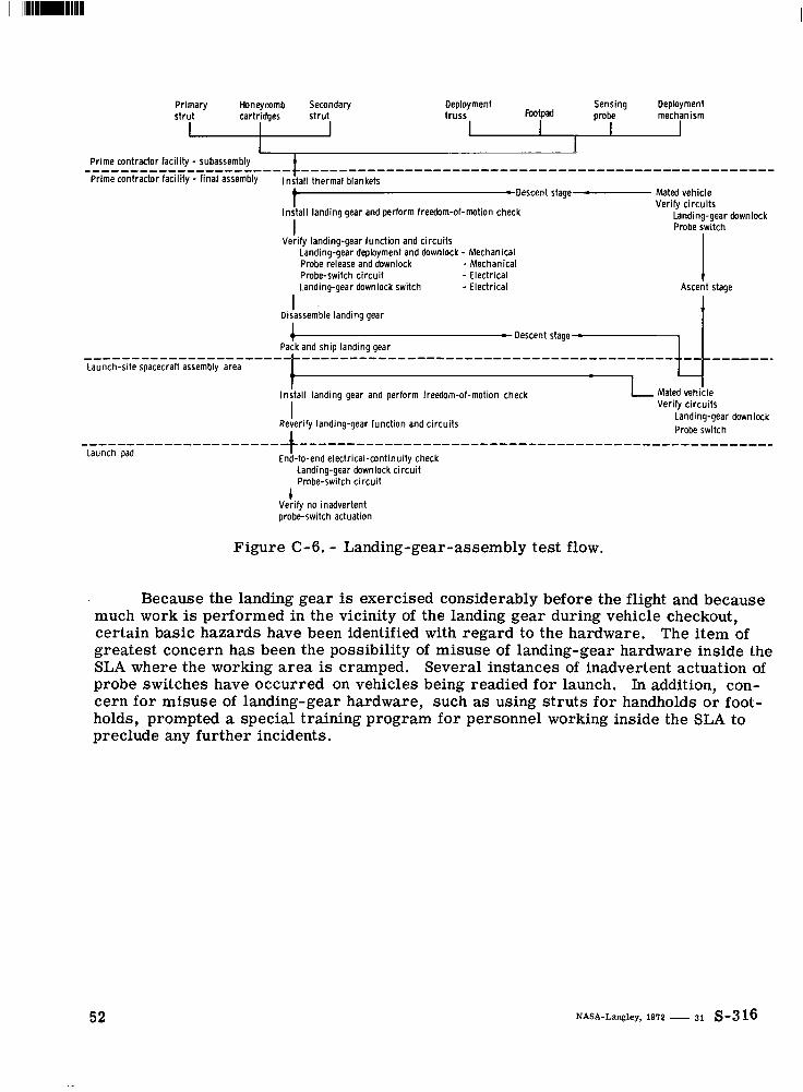
Primary Honeycomb Secondary s t ru t cartridges s t ru t
I I Deployment Sensing Deployment t russ Footpad probe mechanism
I I I
I Insta l l landing gear and perform freedom-of-motion check
Verify landing-gear funct ion and c i rcu i ts I
Landing-gear deployment and downlock - Mechanical Probe release and downlock - Mechanical Probe-switch c i r cu i t - Electrical Landing-gear downlock switch - Electrical
Verify c i r cu i t s Landing-gear downlock Probe switch
1 Ascent stage
I Disassemble landing gear
I Insta l l landing gear and perform freedom-of-motion check
Reverify landing-gear funct ion and c i r cu i t s I I
1 Mated vehi;le Verify c i r cu i t s
Landing-gear downlock Probe switch ..................... -)--------------------------------------------------
End-to-end e ledr ica l -cont inu i ty check Landing-gear downlock c i r cu i t Probe-switch c i r cu i t
Launch pad
1 Verify no inadvertent orobe-switch actuation
Figure C-6. - Landing-gear-assembly test flow.
Because the landing gear is exercised considerably before the flight and because much work is performed in the vicinity of the landing gear during vehicle checkout, certain basic hazards have been identified with regard to the hardware. The item of greatest concern has been the possibility of misuse of landing-gear hardware inside the SLA where the working area is cramped. Several instances of inadvertent actuation of probe switches have occurred on vehicles being readied for launch. In addition, con- cern for misuse of landing-gear hardware, such as using s t ruts for handholds o r foot- holds, prompted a special training program fo r personnel working inside the SLA to preclude any further incidents.
52
I II I1 I I l l Il111l111llll Ill1
N A T I O N A L A E R O N A U T I C S A N D SPACE A D M I S T R A T I O N W A S H I N G T O N . D.C. 20546
~ P O S T A G E A N D FEES P A I D
N A T I O N A L A E R O N A U T I C S A N D
SPACE A D M I N I S T R A T I O N USMAIL
FIRST CLASS MAIL O F F I C I A L B U S I N E S S P E N A L T Y FOR P R I V A T E USE $300
U
NASA 451
If Undeliverable (Section 158 Postal Manual) Do Nor Return
"The aeronautical and space activities of the United Stntes shall be condncted so as to contribute . . . t o the expansion of human knowl- edge of phenomena in the atutosphere and space. T h e Adniinistration shall provide for the widest practicable and appropriate dissenzination of information concerning its actizdies and the results thereof."
-NATIONAL AERONAUTICS AND SPACE ACT OF 1958
NASA SCIENTIFIC A N D TECHNICAL PUBLICATIONS
TECHNICAL REPORTS: Scientific and technical information considered important, complete, and a lasting contribution to existing knowledge.
TECHNICAL NOTES: Information .less broad in scope but nevertheless of importance as a contribution to existing knowledge.
TECHNICAL MEMORANDUMS: Information receiving limited distribution because of preliminary data, security classifica- tion, or other reasons.
TECHNICAL TRANSLATIONS: Information published in a foreign language considered to merit NASA distribution in English.
SPECIAL PUBLICATIONS: Information derived from or of value to NASA activities. Publications include conference pr,oceedings, monographs, data compilations, handbooks, sourcebooks, and special bibliographies.
TECHNOLOGY UTILIZATION PUBLICATIONS: Information on technology used by NASA that may be of particular interest in commercial and other non-aerospace applications. Publications include Tech Briefs, Technology utilization Reports and Technology Surveys.
CONTRACTOR REPORTS: Scientific and technical information generated under a NASA contract or grant and considered an important contribution to existing knowledge.
Details on the availability of these publications may be obtained from:
SCIENTIFIC AND TECHNICAL INFORMATION OFFICE
NATIONAL AERONAUTICS AND SPACE ADMINISTRATION Washington, D.C. PO546