Embed Size (px)
Citation preview
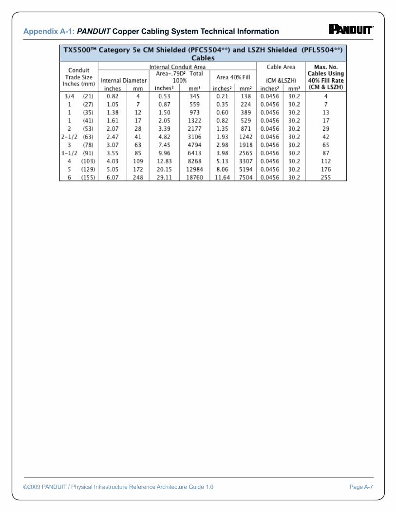
PANDUIT® TX5eTM Copper Cabling Conduit Fill Capacity Table
Appendix A-1: PANDUIT Copper Cabling System Technical Information
©2009 PANDUIT / Physical Infrastructure Reference Architecture Guide 1.0 Page A-5
PANDUIT® TX5e™ Shielded Copper Cabling System Conduit Fill Capacity Table
Appendix A-1: PANDUIT Copper Cabling System Technical Information
©2009 PANDUIT / Physical Infrastructure Reference Architecture Guide 1.0 Page A-6
Appendix A-1: PANDUIT Copper Cabling System Technical Information
©2009 PANDUIT / Physical Infrastructure Reference Architecture Guide 1.0 Page A-7
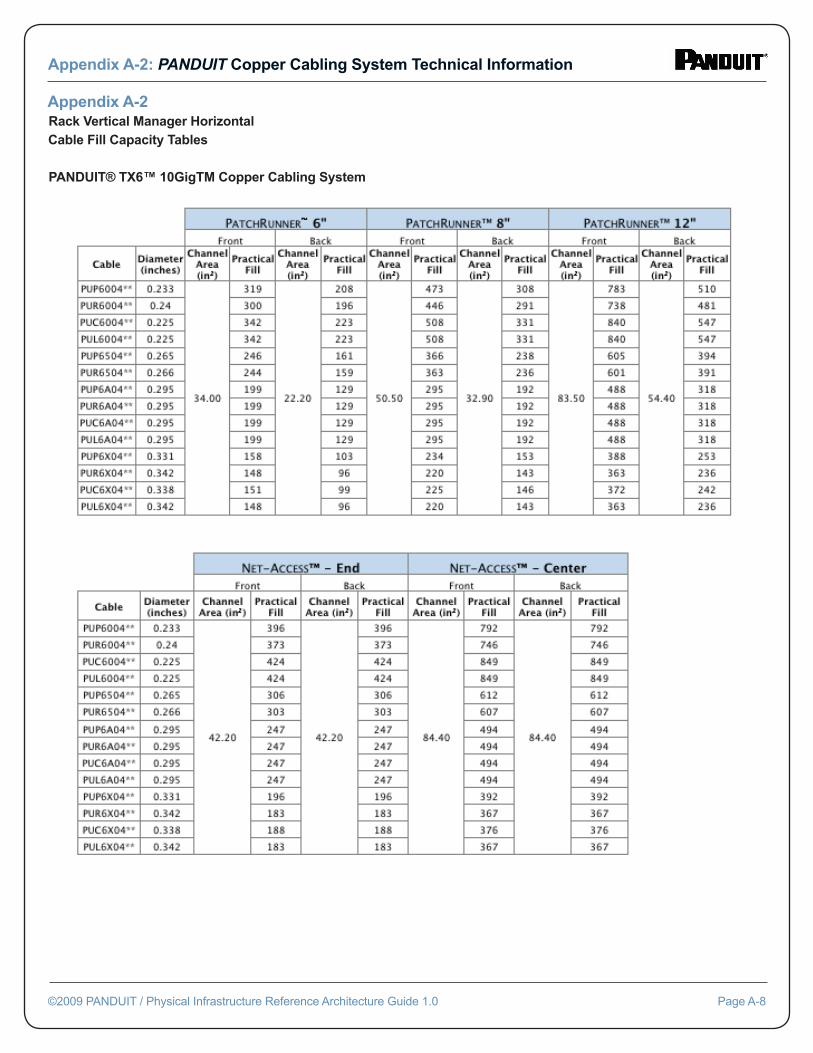
Appendix A-2Rack Vertical Manager Horizontal Cable Fill Capacity Tables
PANDUIT® TX6™ 10GigTM Copper Cabling System
Appendix A-2: PANDUIT Copper Cabling System Technical Information
©2009 PANDUIT / Physical Infrastructure Reference Architecture Guide 1.0 Page A-8
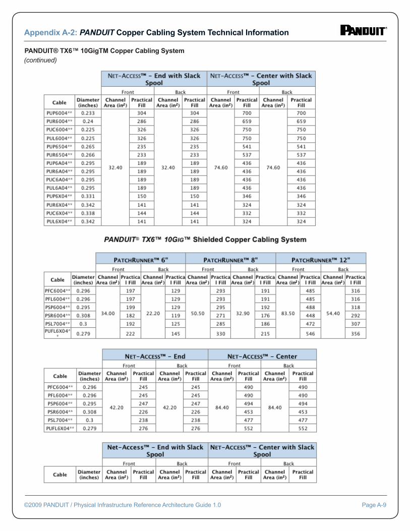
PANDUIT® TX6™ 10GigTM Copper Cabling System(continued)
Appendix A-2: PANDUIT Copper Cabling System Technical Information
©2009 PANDUIT / Physical Infrastructure Reference Architecture Guide 1.0 Page A-9
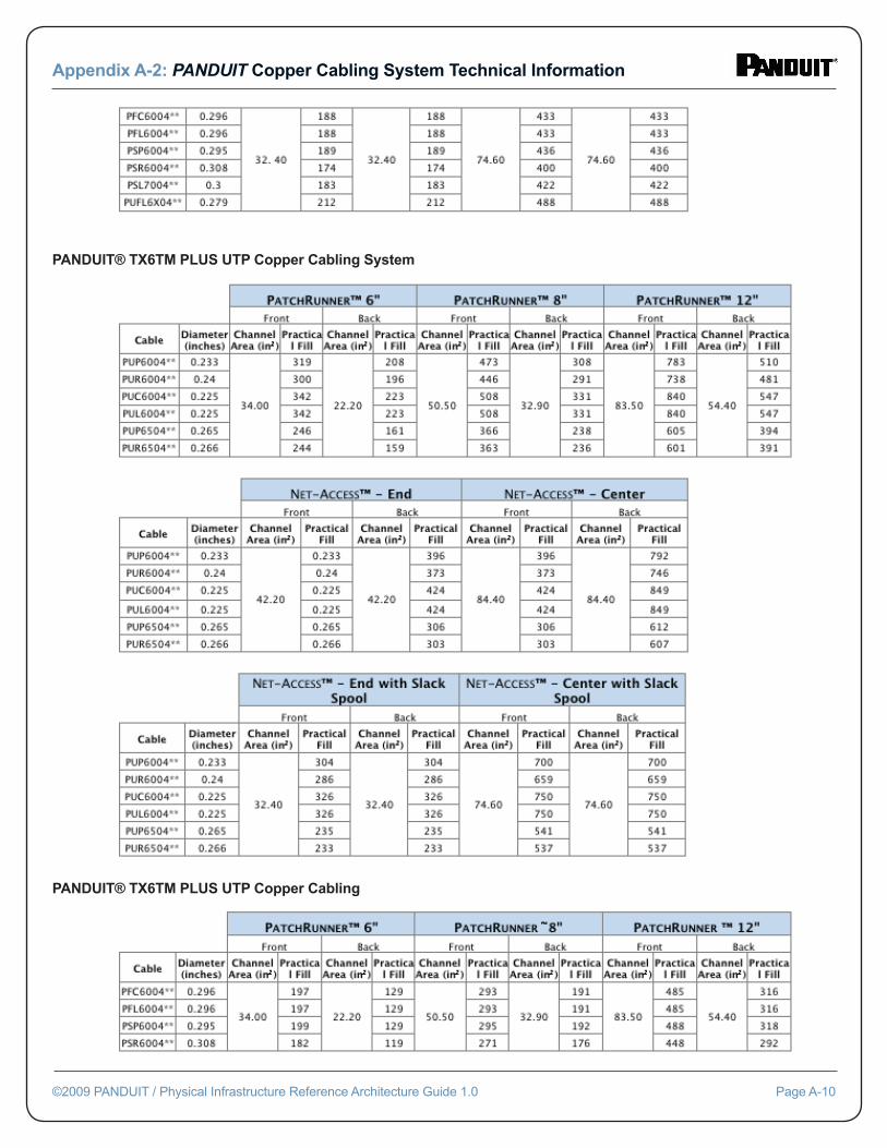
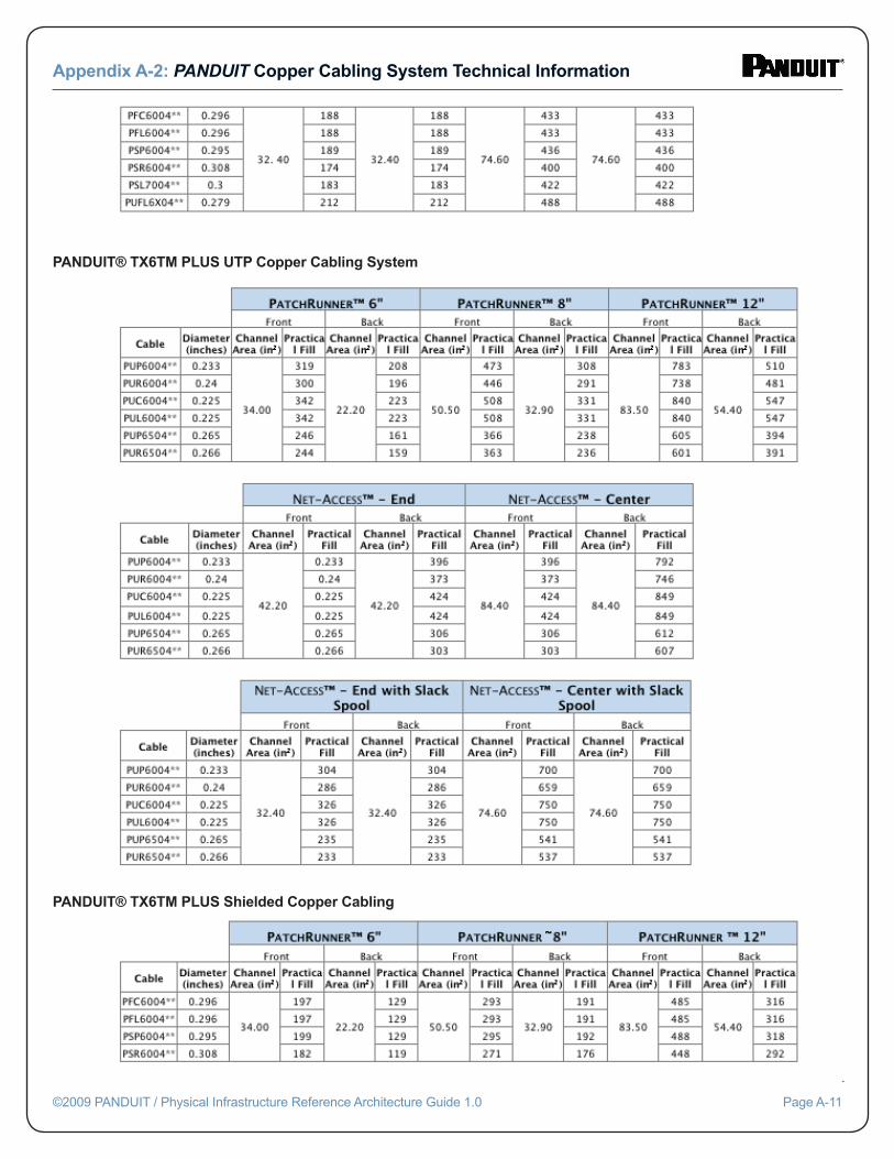
PANDUIT® TX6™ PLUS UTP Copper Cabling System
PANDUIT® TX6TM PLUS Shielded Copper Cabling
Appendix A-2: PANDUIT Copper Cabling System Technical Information
©2009 PANDUIT / Physical Infrastructure Reference Architecture Guide 1.0 Page A-10
PANDUIT® TX6TM PLUS UTP Copper Cabling
PANDUIT® TX6TM PLUS UTP Copper Cabling System
Appendix A-2: PANDUIT Copper Cabling System Technical Information
©2009 PANDUIT / Physical Infrastructure Reference Architecture Guide 1.0 Page A-11
PANDUIT® TX6TM PLUS Shielded Copper Cabling
PANDUIT® TX6TM PLUS UTP Copper Cabling System
Appendix A-2: PANDUIT Copper Cabling System Technical Information
©2009 PANDUIT / Physical Infrastructure Reference Architecture Guide 1.0 Page A-12
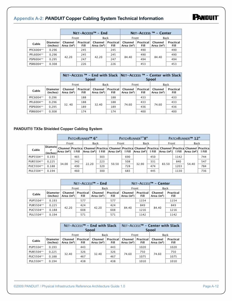
PANDUIT® TX5e Shielded Copper Cabling System
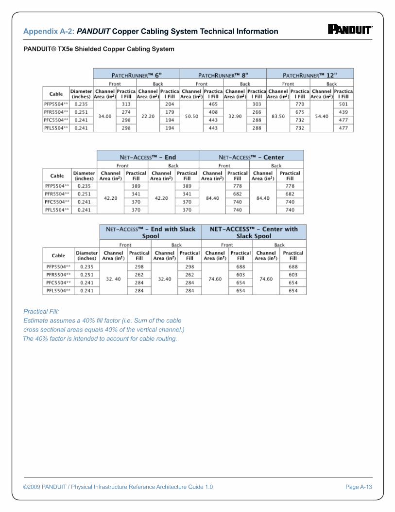
PANDUIT® TX5e Shielded Copper Cabling System
Practical Fill: Estimate assumes a 40% fi ll factor (i.e. Sum of the cable cross sectional areas equals 40% of the vertical channel.) The 40% factor is intended to account for cable routing.
Appendix A-2: PANDUIT Copper Cabling System Technical Information
©2009 PANDUIT / Physical Infrastructure Reference Architecture Guide 1.0 Page A-13
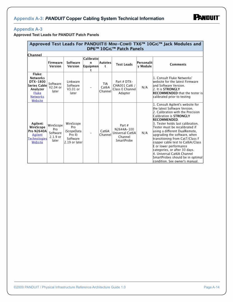
Appendix A-3Approved Test Leads for PANDUIT Patch Panels
Appendix A-3: PANDUIT Copper Cabling System Technical Information
©2009 PANDUIT / Physical Infrastructure Reference Architecture Guide 1.0 Page A-14
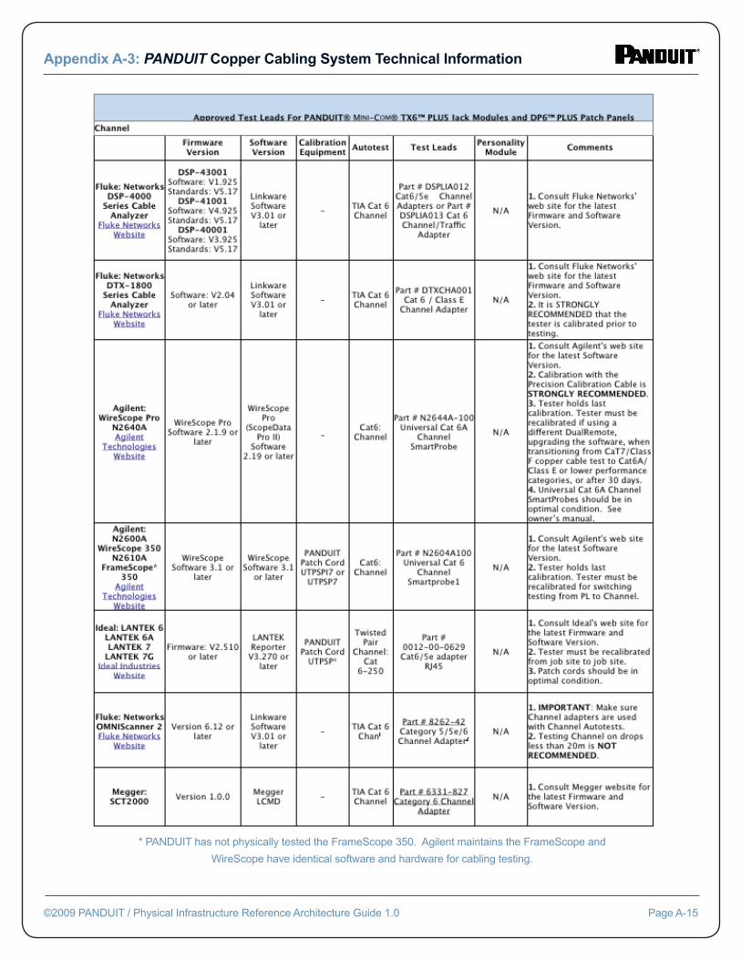
Appendix A-3: PANDUIT Copper Cabling System Technical Information
©2009 PANDUIT / Physical Infrastructure Reference Architecture Guide 1.0 Page A-15
* PANDUIT has not physically tested the FrameScope 350. Agilent maintains the FrameScope and
WireScope have identical software and hardware for cabling testing.
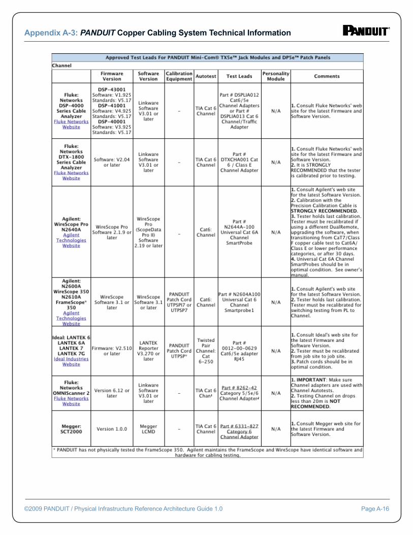
Appendix A-3: PANDUIT Copper Cabling System Technical Information
©2009 PANDUIT / Physical Infrastructure Reference Architecture Guide 1.0 Page A-16
Appendix A-4PANDUIT Copper Cabling System Product Specifi cation Details
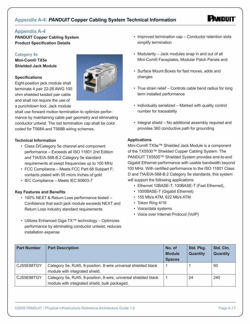
Category 5eMini-Com® TX5e Shielded Jack Module Specifi cationsEight-position jack module shall terminate 4 pair 22-26 AWG 100 ohm shielded twisted pair cable and shall not require the use of a punchdown tool. Jack module shall use forward motion termination to optimize perfor-mance by maintaining cable pair geometry and eliminating conductor untwist. The red termination cap shall be color coded for T568A and T568B wiring schemes.
Technical Information • Class D/Category 5e channel and component performance – Exceeds all ISO 11801 2nd Edition and TIA/EIA-568-B.2 Category 5e standard requirements at swept frequencies up to 100 MHz • FCC Compliance – Meets FCC Part 68 Subpart F; contacts plated with 50 micro inches of gold • IEC Compliance – Meets IEC 60603-7
Key Features and Benefi ts • 100% NEXT & Return Loss performance tested – Confi dence that each jack module exceeds NEXT and Return Loss industry standard requirements
• Utilizes Enhanced Giga-TX™ technology – Optimizes performance by eliminating conductor untwist; reduces installation expense
• Improved termination cap – Conductor retention slots simplify termination
• Modularity – Jack modules snap in and out of all Mini-Com® Faceplates, Modular Patch Panels and
• Surface Mount Boxes for fast moves, adds and changes
• True strain relief – Controls cable bend radius for long term installed performance
• Individually serialized – Marked with quality control number for traceability
• Integral shield – No additional assembly required and provides 360 conductive path for grounding
ApplicationsMini-Com® TX5e™ Shielded Jack Module is a component of the TX5500™ Shielded Copper Cabling System. The PANDUIT TX5500™ Shielded System provides end-to-end Gigabit Ethernet performance with usable bandwidth beyond 100 MHz. With certifi ed performance to the ISO 11801 Class D and TIA/EIA-568-B.2 Category 5e standards, this system will support the following applications: • Ethernet 10BASE-T, 100BASE-T (Fast Ethernet), • 1000BASE-T (Gigabit Ethernet) • 155 Mb/s ATM, 622 Mb/s ATM • Token Ring 4/16 • Voice/data systems • Voice over Internet Protocol (VoIP)
Appendix A-4: PANDUIT Copper Cabling System Technical Information
©2009 PANDUIT / Physical Infrastructure Reference Architecture Guide 1.0 Page A-17
Part Number Part Description No. of Module Spaces
Std. Pkg. Quantity
Std. Ctn. Quantity
CJS5E88TGY Category 5e, RJ45, 8-position, 8-wire universal shielded black module with integrated shield.
1 1 50
CJS5E88TGY Category 5e, RJ45, 8-position, 8-wire, universal shielded black module with integrated shield, bulk packaged.
1 24 240
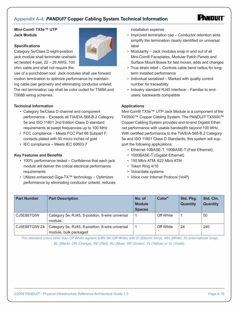
Mini-Com® TX5e™ UTP Jack Module Specifi cationsCategory 5e/Class D eight-position jack module shall terminate unshield-ed twisted 4-pair, 22 – 26 AWG, 100 ohm cable and shall not require the use of a punchdown tool. Jack modules shall use forward motion termination to optimize performance by maintain-ing cable pair geometry and eliminating conductor untwist. The red termination cap shall be color coded for T568A and T568B wiring schemes.
Technical Information • Category 5e/Class D channel and component performance – Exceeds all TIA/EIA-568-B.2 Category 5e and ISO 11801 2nd Edition Class D standard requirements at swept frequencies up to 100 MHz • FCC compliance – Meets FCC Part 68 Subpart F; contacts plated with 50 micro inches of gold • IEC compliance – Meets IEC 60603-7
Key Features and Benefi ts • 100% performance tested – Confi dence that each jack module will deliver the critical electrical performance requirements • Utilizes enhanced Giga-TX™ technology – Optimizes performance by eliminating conductor untwist; reduces
installation expense • Improved termination cap – Conductor retention slots simplify the termination clearly identifi ed on universal label • Modularity – Jack modules snap in and out of all Mini-Com® Faceplates, Modular Patch Panels and Surface Mount Boxes for fast moves, adds and changes • True strain relief – Controls cable bend radius for long- term installed performance • Individual serialized – Marked with quality control number for traceability • Industry standard RJ45 interface – Familiar to end- users; backwards compatible
ApplicationsMini-Com® TX5e™ UTP Jack Module is a component of the TX5500™ Copper Cabling System. The PANDUIT TX5500™ Copper Cabling System provides end-to-end Gigabit Ether-net performance with usable bandwidth beyond 100 MHz. With certifi ed performance to the TIA/EIA-568-B.2 Category 5e and ISO 11801 Class D Standards, this system will sup-port the following applications: • Ethernet 10BASE-T, 100BASE-T (Fast Ethernet), • 1000BASE-T (Gigabit Ethernet) • 155 Mb/s ATM, 622 Mb/s ATM • Token Ring 4/16 • Voice/data systems • Voice over Internet Protocol (VoIP)
Appendix A-4: PANDUIT Copper Cabling System Technical Information
©2009 PANDUIT / Physical Infrastructure Reference Architecture Guide 1.0 Page A-18
Part Number Part Description No. of Module Spaces
Color* Std. Pkg. Quantity
Std. Ctn. Quantity
CJ5E88TGIW Category 5e, RJ45, 8-position, 8-wire universal module.
1 Off White 1 50
CJ5E88TGIW-24 Category 5e, RJ45, 8-position, 8-wire universal module, bulk packaged
1 Off White 24 240
*For standard colors other than Off White, replace suffi x IW (Off White) with EI (Electric Ivory), WH (White), IG (international Gray),
BL (Black), OR (Orange), RD (Red), BU (Blue), GR (Green), YL (Yellow) or VL (Violet).
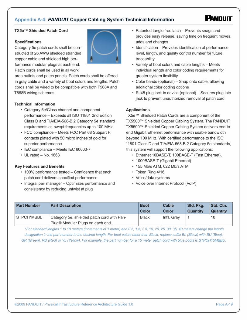
TX5e™ Shielded Patch Cord Specifi cationsCategory 5e patch cords shall be con-structed of 26 AWG shielded stranded copper cable and shielded high per-formance modular plugs at each end. Patch cords shall be used in all work area outlets and patch panels. Patch cords shall be offered in gray cable and a variety of boot colors and lengths. Patch cords shall be wired to be compatible with both T568A and T568B wiring schemes.
Technical Information • Category 5e/Class channel and component performance – Exceeds all ISO 11801 2nd Edition Class D and TIA/EIA-568-B.2 Category 5e standard requirements at swept frequencies up to 100 MHz • FCC compliance – Meets FCC Part 68 Subpart F; contacts plated with 50 micro inches of gold for superior performance • IEC compliance – Meets IEC 60603-7 • UL rated – No. 1863
Key Features and Benefi ts • 100% performance tested – Confi dence that each patch cord delivers specifi ed performance • Integral pair manager – Optimizes performance and consistency by reducing untwist at plug
• Patented tangle free latch – Prevents snags and provides easy release, saving time on frequent moves, adds and changes • Identifi cation – Provides identifi cation of performance level, length, and quality control number for future traceability • Variety of boot colors and cable lengths – Meets individual length and color coding requirements for greater system fl exibility • Color bands (optional) – Snap onto cable, allowing additional color coding options • RJ45 plug lock-in device (optional) – Secures plug into jack to prevent unauthorized removal of patch cord
ApplicationsTX5e™ Shielded Patch Cords are a component of the TX5500™ Shielded Copper Cabling System. The PANDUIT TX5500™ Shielded Copper Cabling System delivers end-to-end Gigabit Ethernet performance with usable bandwidth beyond 100 MHz. With certifi ed performance to the ISO 11801 Class D and TIA/EIA-568-B.2 Category 5e standards, this system will support the following applications: • Ethernet 10BASE-T, 100BASE-T (Fast Ethernet), • 1000BASE-T (Gigabit Ethernet) • 155 Mb/s ATM, 622 Mb/s ATM • Token Ring 4/16 • Voice/data systems • Voice over Internet Protocol (VoIP)
Appendix A-4: PANDUIT Copper Cabling System Technical Information
©2009 PANDUIT / Physical Infrastructure Reference Architecture Guide 1.0 Page A-19
Part Number Part Description Boot Color
Cable Color
Std. Pkg. Quantity
Std. Ctn. Quantity
STPCH*MBBL Category 5e, shielded patch cord with Pan-Plug® Modular Plugs on each end..
Black Int’l. Gray 1 10
*For standard lengths 1 to 10 meters (increments of 1 meter) and 0.5, 1.5, 2.5, 15, 20, 25, 30, 35, 40 meters change the length
designation in the part number to the desired length. For boot colors other than Black, replace suffi x BL (Black) with BU (Blue),
GR (Green), RD (Red) or YL (Yellow). For example, the part number for a 15 meter patch cord with blue boots is STPCH15MBBU.
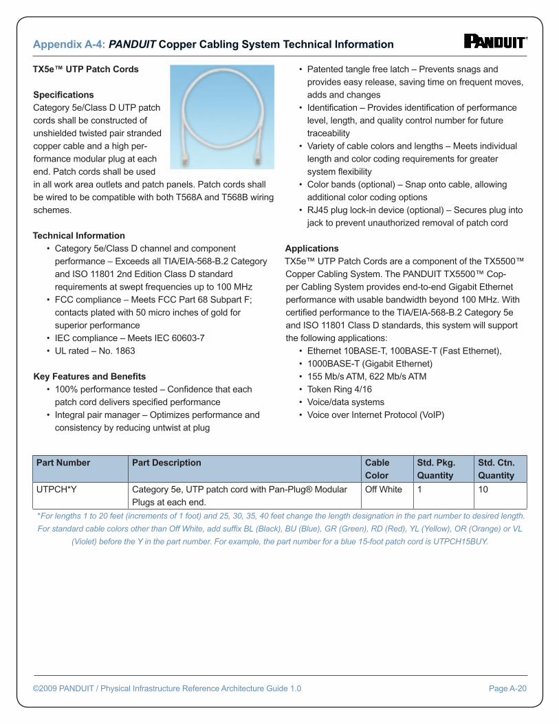
TX5e™ UTP Patch Cords Specifi cationsCategory 5e/Class D UTP patch cords shall be constructed of unshielded twisted pair stranded copper cable and a high per-formance modular plug at each end. Patch cords shall be used in all work area outlets and patch panels. Patch cords shall be wired to be compatible with both T568A and T568B wiring schemes.
Technical Information • Category 5e/Class D channel and component performance – Exceeds all TIA/EIA-568-B.2 Category and ISO 11801 2nd Edition Class D standard requirements at swept frequencies up to 100 MHz • FCC compliance – Meets FCC Part 68 Subpart F; contacts plated with 50 micro inches of gold for superior performance • IEC compliance – Meets IEC 60603-7 • UL rated – No. 1863
Key Features and Benefi ts • 100% performance tested – Confi dence that each patch cord delivers specifi ed performance • Integral pair manager – Optimizes performance and consistency by reducing untwist at plug
• Patented tangle free latch – Prevents snags and provides easy release, saving time on frequent moves, adds and changes • Identifi cation – Provides identifi cation of performance level, length, and quality control number for future traceability • Variety of cable colors and lengths – Meets individual length and color coding requirements for greater system fl exibility • Color bands (optional) – Snap onto cable, allowing additional color coding options • RJ45 plug lock-in device (optional) – Secures plug into jack to prevent unauthorized removal of patch cord
ApplicationsTX5e™ UTP Patch Cords are a component of the TX5500™ Copper Cabling System. The PANDUIT TX5500™ Cop-per Cabling System provides end-to-end Gigabit Ethernet performance with usable bandwidth beyond 100 MHz. With certifi ed performance to the TIA/EIA-568-B.2 Category 5e and ISO 11801 Class D standards, this system will support the following applications: • Ethernet 10BASE-T, 100BASE-T (Fast Ethernet), • 1000BASE-T (Gigabit Ethernet) • 155 Mb/s ATM, 622 Mb/s ATM • Token Ring 4/16 • Voice/data systems • Voice over Internet Protocol (VoIP)
Appendix A-4: PANDUIT Copper Cabling System Technical Information
©2009 PANDUIT / Physical Infrastructure Reference Architecture Guide 1.0 Page A-20
Part Number Part Description Cable Color
Std. Pkg. Quantity
Std. Ctn. Quantity
UTPCH*Y Category 5e, UTP patch cord with Pan-Plug® Modular Plugs at each end.
Off White 1 10
*For lengths 1 to 20 feet (increments of 1 foot) and 25, 30, 35, 40 feet change the length designation in the part number to desired length.
For standard cable colors other than Off White, add suffi x BL (Black), BU (Blue), GR (Green), RD (Red), YL (Yellow), OR (Orange) or VL
(Violet) before the Y in the part number. For example, the part number for a blue 15-foot patch cord is UTPCH15BUY.
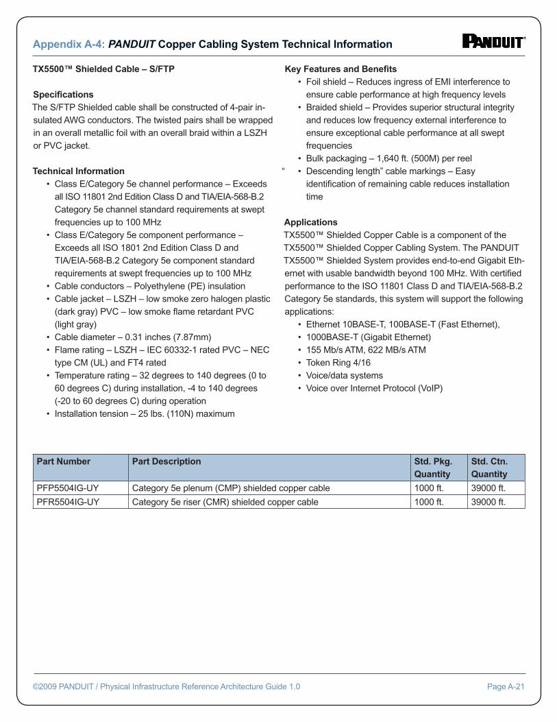
TX5500™ Shielded Cable – S/FTP
Specifi cationsThe S/FTP Shielded cable shall be constructed of 4-pair in-sulated AWG conductors. The twisted pairs shall be wrapped in an overall metallic foil with an overall braid within a LSZH or PVC jacket.
Technical Information • Class E/Category 5e channel performance – Exceeds all ISO 11801 2nd Edition Class D and TIA/EIA-568-B.2 Category 5e channel standard requirements at swept frequencies up to 100 MHz • Class E/Category 5e component performance – Exceeds all ISO 1801 2nd Edition Class D and TIA/EIA-568-B.2 Category 5e component standard requirements at swept frequencies up to 100 MHz • Cable conductors – Polyethylene (PE) insulation • Cable jacket – LSZH – low smoke zero halogen plastic (dark gray) PVC – low smoke fl ame retardant PVC (light gray) • Cable diameter – 0.31 inches (7.87mm) • Flame rating – LSZH – IEC 60332-1 rated PVC – NEC type CM (UL) and FT4 rated • Temperature rating – 32 degrees to 140 degrees (0 to 60 degrees C) during installation, -4 to 140 degrees (-20 to 60 degrees C) during operation • Installation tension – 25 lbs. (110N) maximum
Key Features and Benefi ts • Foil shield – Reduces ingress of EMI interference to ensure cable performance at high frequency levels • Braided shield – Provides superior structural integrity and reduces low frequency external interference to ensure exceptional cable performance at all swept frequencies • Bulk packaging – 1,640 ft. (500M) per reel“ • Descending length” cable markings – Easy identifi cation of remaining cable reduces installation time
ApplicationsTX5500™ Shielded Copper Cable is a component of the TX5500™ Shielded Copper Cabling System. The PANDUIT TX5500™ Shielded System provides end-to-end Gigabit Eth-ernet with usable bandwidth beyond 100 MHz. With certifi ed performance to the ISO 11801 Class D and TIA/EIA-568-B.2 Category 5e standards, this system will support the following applications: • Ethernet 10BASE-T, 100BASE-T (Fast Ethernet), • 1000BASE-T (Gigabit Ethernet) • 155 Mb/s ATM, 622 MB/s ATM • Token Ring 4/16 • Voice/data systems • Voice over Internet Protocol (VoIP)
Appendix A-4: PANDUIT Copper Cabling System Technical Information
©2009 PANDUIT / Physical Infrastructure Reference Architecture Guide 1.0 Page A-21
Part Number Part Description Std. Pkg. Quantity
Std. Ctn. Quantity
PFP5504IG-UY Category 5e plenum (CMP) shielded copper cable 1000 ft. 39000 ft.
PFR5504IG-UY Category 5e riser (CMR) shielded copper cable 1000 ft. 39000 ft.
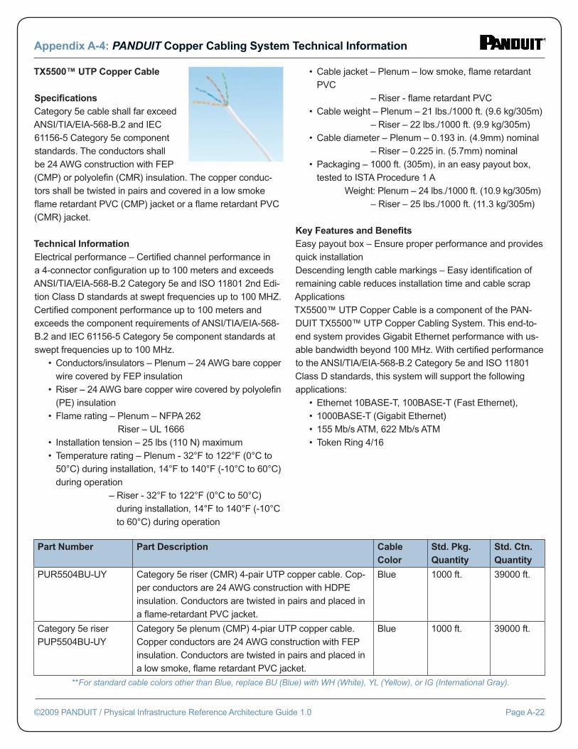
TX5500™ UTP Copper Cable Specifi cationsCategory 5e cable shall far exceed ANSI/TIA/EIA-568-B.2 and IEC 61156-5 Category 5e component standards. The conductors shall be 24 AWG construction with FEP (CMP) or polyolefi n (CMR) insulation. The copper conduc-tors shall be twisted in pairs and covered in a low smoke fl ame retardant PVC (CMP) jacket or a fl ame retardant PVC (CMR) jacket.
Technical InformationElectrical performance – Certifi ed channel performance in a 4-connector confi guration up to 100 meters and exceeds ANSI/TIA/EIA-568-B.2 Category 5e and ISO 11801 2nd Edi-tion Class D standards at swept frequencies up to 100 MHZ. Certifi ed component performance up to 100 meters and exceeds the component requirements of ANSI/TIA/EIA-568-B.2 and IEC 61156-5 Category 5e component standards at swept frequencies up to 100 MHz. • Conductors/insulators – Plenum – 24 AWG bare copper wire covered by FEP insulation • Riser – 24 AWG bare copper wire covered by polyolefi n (PE) insulation • Flame rating – Plenum – NFPA 262 Riser – UL 1666 • Installation tension – 25 lbs (110 N) maximum • Temperature rating – Plenum - 32°F to 122°F (0°C to 50°C) during installation, 14°F to 140°F (-10°C to 60°C) during operation – Riser - 32°F to 122°F (0°C to 50°C) during installation, 14°F to 140°F (-10°C to 60°C) during operation
• Cable jacket – Plenum – low smoke, fl ame retardant PVC – Riser - fl ame retardant PVC • Cable weight – Plenum – 21 lbs./1000 ft. (9.6 kg/305m) – Riser – 22 lbs./1000 ft. (9.9 kg/305m) • Cable diameter – Plenum – 0.193 in. (4.9mm) nominal – Riser – 0.225 in. (5.7mm) nominal • Packaging – 1000 ft. (305m), in an easy payout box, tested to ISTA Procedure 1 A Weight: Plenum – 24 lbs./1000 ft. (10.9 kg/305m) – Riser – 25 lbs./1000 ft. (11.3 kg/305m)
Key Features and Benefi tsEasy payout box – Ensure proper performance and provides quick installationDescending length cable markings – Easy identifi cation of remaining cable reduces installation time and cable scrapApplicationsTX5500™ UTP Copper Cable is a component of the PAN-DUIT TX5500™ UTP Copper Cabling System. This end-to-end system provides Gigabit Ethernet performance with us-able bandwidth beyond 100 MHz. With certifi ed performance to the ANSI/TIA/EIA-568-B.2 Category 5e and ISO 11801 Class D standards, this system will support the following applications: • Ethernet 10BASE-T, 100BASE-T (Fast Ethernet), • 1000BASE-T (Gigabit Ethernet) • 155 Mb/s ATM, 622 Mb/s ATM • Token Ring 4/16
Appendix A-4: PANDUIT Copper Cabling System Technical Information
©2009 PANDUIT / Physical Infrastructure Reference Architecture Guide 1.0 Page A-22
Part Number Part Description Cable Color
Std. Pkg. Quantity
Std. Ctn. Quantity
PUR5504BU-UY Category 5e riser (CMR) 4-pair UTP copper cable. Cop-per conductors are 24 AWG construction with HDPE insulation. Conductors are twisted in pairs and placed in a fl ame-retardant PVC jacket.
Blue 1000 ft. 39000 ft.
Category 5e riser PUP5504BU-UY
Category 5e plenum (CMP) 4-piar UTP copper cable. Copper conductors are 24 AWG construction with FEP insulation. Conductors are twisted in pairs and placed in a low smoke, fl ame retardant PVC jacket.
Blue 1000 ft. 39000 ft.
**For standard cable colors other than Blue, replace BU (Blue) with WH (White), YL (Yellow), or IG (International Gray).
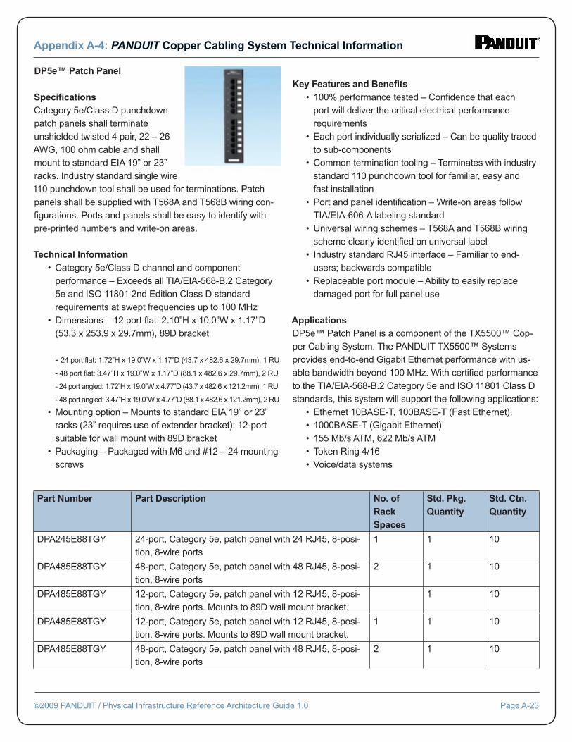
DP5e™ Patch Panel Specifi cationsCategory 5e/Class D punchdown patch panels shall terminate unshielded twisted 4 pair, 22 – 26 AWG, 100 ohm cable and shall mount to standard EIA 19” or 23” racks. Industry standard single wire 110 punchdown tool shall be used for terminations. Patch panels shall be supplied with T568A and T568B wiring con-fi gurations. Ports and panels shall be easy to identify with pre-printed numbers and write-on areas.
Technical Information • Category 5e/Class D channel and component performance – Exceeds all TIA/EIA-568-B.2 Category 5e and ISO 11801 2nd Edition Class D standard requirements at swept frequencies up to 100 MHz • Dimensions – 12 port fl at: 2.10”H x 10.0”W x 1.17”D (53.3 x 253.9 x 29.7mm), 89D bracket - 24 port fl at: 1.72”H x 19.0”W x 1.17”D (43.7 x 482.6 x 29.7mm), 1 RU
- 48 port fl at: 3.47”H x 19.0”W x 1.17”D (88.1 x 482.6 x 29.7mm), 2 RU
- 24 port angled: 1.72”H x 19.0”W x 4.77”D (43.7 x 482.6 x 121.2mm), 1 RU
- 48 port angled: 3.47”H x 19.0”W x 4.77”D (88.1 x 482.6 x 121.2mm), 2 RU
• Mounting option – Mounts to standard EIA 19” or 23” racks (23” requires use of extender bracket); 12-port suitable for wall mount with 89D bracket • Packaging – Packaged with M6 and #12 – 24 mounting screws
Key Features and Benefi ts • 100% performance tested – Confi dence that each port will deliver the critical electrical performance requirements • Each port individually serialized – Can be quality traced to sub-components • Common termination tooling – Terminates with industry standard 110 punchdown tool for familiar, easy and fast installation • Port and panel identifi cation – Write-on areas follow TIA/EIA-606-A labeling standard • Universal wiring schemes – T568A and T568B wiring scheme clearly identifi ed on universal label • Industry standard RJ45 interface – Familiar to end- users; backwards compatible • Replaceable port module – Ability to easily replace damaged port for full panel use
ApplicationsDP5e™ Patch Panel is a component of the TX5500™ Cop-per Cabling System. The PANDUIT TX5500™ Systems provides end-to-end Gigabit Ethernet performance with us-able bandwidth beyond 100 MHz. With certifi ed performance to the TIA/EIA-568-B.2 Category 5e and ISO 11801 Class D standards, this system will support the following applications: • Ethernet 10BASE-T, 100BASE-T (Fast Ethernet), • 1000BASE-T (Gigabit Ethernet) • 155 Mb/s ATM, 622 Mb/s ATM • Token Ring 4/16 • Voice/data systems
Appendix A-4: PANDUIT Copper Cabling System Technical Information
©2009 PANDUIT / Physical Infrastructure Reference Architecture Guide 1.0 Page A-23
Part Number Part Description No. of Rack Spaces
Std. Pkg. Quantity
Std. Ctn. Quantity
DPA245E88TGY 24-port, Category 5e, patch panel with 24 RJ45, 8-posi-tion, 8-wire ports
1 1 10
DPA485E88TGY 48-port, Category 5e, patch panel with 48 RJ45, 8-posi-tion, 8-wire ports
2 1 10
DPA485E88TGY 12-port, Category 5e, patch panel with 12 RJ45, 8-posi-tion, 8-wire ports. Mounts to 89D wall mount bracket.
1 10
DPA485E88TGY 12-port, Category 5e, patch panel with 12 RJ45, 8-posi-tion, 8-wire ports. Mounts to 89D wall mount bracket.
1 1 10
DPA485E88TGY 48-port, Category 5e, patch panel with 48 RJ45, 8-posi-tion, 8-wire ports
2 1 10
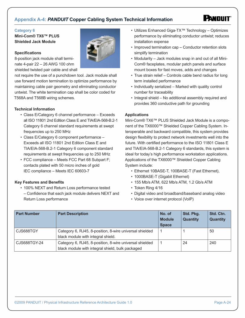
Category 6Mini-Com® TX6™ PLUS Shielded Jack Module
Specifi cations8-position jack module shall termi-nate 4-pair 22 – 26 AWG 100 ohm shielded twisted pair cable and shall not require the use of a punchdown tool. Jack module shall use forward motion termination to optimize performance by maintaining cable pair geometry and eliminating conductor untwist. The white termination cap shall be color coded for T568A and T568B wiring schemes.
Technical Information • Class E/Category 6 channel performance – Exceeds all ISO 11801 2nd Edition Class E and TIA/EIA-568-B.2-1 Category 6 channel standard requirements at swept frequencies up to 250 MHz • Class E/Category 6 component performance – Exceeds all ISO 11801 2nd Edition Class E and TIA/EIA-568-B.2-1 Category 6 component standard requirements at swept frequencies up to 250 MHz • FCC compliance – Meets FCC Part 68 Subpart F; contacts plated with 50 micro inches of gold IEC compliance – Meets IEC 60603-7
Key Features and Benefi ts • 100% NEXT and Return Loss performance tested – Confi dence that each jack module delivers NEXT and Return Loss performance
• Utilizes Enhanced Giga-TX™ Technology – Optimizes performance by eliminating conductor untwist; reduces installation expense • Improved termination cap – Conductor retention slots simplify termination • Modularity – Jack modules snap in and out of all Mini- Com® faceplates, modular patch panels and surface mount boxes for fast moves, adds and changes • True strain relief – Controls cable bend radius for long term installed performance • Individually serialized – Marked with quality control number for traceability • Integral shield – No additional assembly required and provides 360 conductive path for grounding
ApplicationsMini-Com® TX6™ PLUS Shielded Jack Module is a compo-nent of the TX6000™ Shielded Copper Cabling System. In-teroperable and backward compatible, this system provides design fl exibility to protect network investments well into the future. With certifi ed performance to the ISO 11801 Class E and TIA/EIA-568-B.2-1 Category 6 standards, this system is ideal for today’s high performance workstation applications. Applications of the TX6000™ Shielded Copper Cabling System include: • Ethernet 10BASE-T, 100BASE-T (Fast Ethernet), • 1000BASE-T (Gigabit Ethernet) • 155 Mb/s ATM, 622 Mb/s ATM, 1.2 Gb/s ATM • Token Ring 4/16 • Digital video and broadband/baseband analog video • Voice over internet protocol (VoIP)
Appendix A-4: PANDUIT Copper Cabling System Technical Information
©2009 PANDUIT / Physical Infrastructure Reference Architecture Guide 1.0 Page A-24
Part Number Part Description No. of Module Space
Std. Pkg. Quantity
Std. Ctn. Quantity
CJS688TGY Category 6, RJ45, 8-position, 8-wire universal shielded black module with integral shield.
1 1 50
CJS688TGY-24 Category 6, RJ45, 8-position, 8-wire universal shielded black module with integral shield, bulk packaged
1 24 240
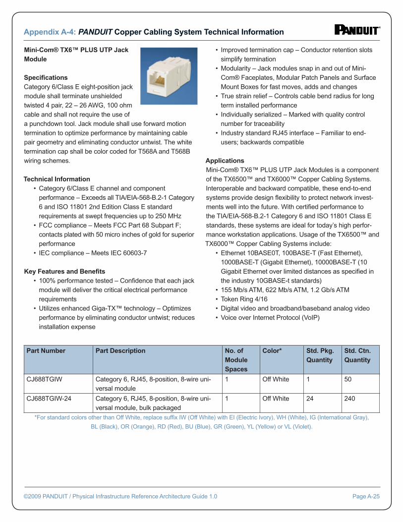
Mini-Com® TX6™ PLUS UTP Jack Module Specifi cationsCategory 6/Class E eight-position jack module shall terminate unshielded twisted 4 pair, 22 – 26 AWG, 100 ohm cable and shall not require the use of a punchdown tool. Jack module shall use forward motion termination to optimize performance by maintaining cable pair geometry and eliminating conductor untwist. The white termination cap shall be color coded for T568A and T568B wiring schemes.
Technical Information • Category 6/Class E channel and component performance – Exceeds all TIA/EIA-568-B.2-1 Category 6 and ISO 11801 2nd Edition Class E standard requirements at swept frequencies up to 250 MHz • FCC compliance – Meets FCC Part 68 Subpart F; contacts plated with 50 micro inches of gold for superior performance • IEC compliance – Meets IEC 60603-7
Key Features and Benefi ts • 100% performance tested – Confi dence that each jack module will deliver the critical electrical performance requirements • Utilizes enhanced Giga-TX™ technology – Optimizes performance by eliminating conductor untwist; reduces installation expense
• Improved termination cap – Conductor retention slots simplify termination • Modularity – Jack modules snap in and out of Mini- Com® Faceplates, Modular Patch Panels and Surface Mount Boxes for fast moves, adds and changes • True strain relief – Controls cable bend radius for long term installed performance • Individually serialized – Marked with quality control number for traceability • Industry standard RJ45 interface – Familiar to end- users; backwards compatible
ApplicationsMini-Com® TX6™ PLUS UTP Jack Modules is a component of the TX6500™ and TX6000™ Copper Cabling Systems. Interoperable and backward compatible, these end-to-end systems provide design fl exibility to protect network invest-ments well into the future. With certifi ed performance to the TIA/EIA-568-B.2-1 Category 6 and ISO 11801 Class E standards, these systems are ideal for today’s high perfor-mance workstation applications. Usage of the TX6500™ and TX6000™ Copper Cabling Systems include: • Ethernet 10BASE0T, 100BASE-T (Fast Ethernet), 1000BASE-T (Gigabit Ethernet), 10000BASE-T (10 Gigabit Ethernet over limited distances as specifi ed in the industry 10GBASE-t standards) • 155 Mb/s ATM, 622 Mb/s ATM, 1.2 Gb/s ATM • Token Ring 4/16 • Digital video and broadband/baseband analog video • Voice over Internet Protocol (VoIP)
Appendix A-4: PANDUIT Copper Cabling System Technical Information
©2009 PANDUIT / Physical Infrastructure Reference Architecture Guide 1.0 Page A-25
Part Number Part Description No. of Module Spaces
Color* Std. Pkg. Quantity
Std. Ctn. Quantity
CJ688TGIW Category 6, RJ45, 8-position, 8-wire uni-versal module
1 Off White 1 50
CJ688TGIW-24 Category 6, RJ45, 8-position, 8-wire uni-versal module, bulk packaged
1 Off White 24 240
*For standard colors other than Off White, replace suffi x IW (Off White) with EI (Electric Ivory), WH (White), IG (International Gray),
BL (Black), OR (Orange), RD (Red), BU (Blue), GR (Green), YL (Yellow) or VL (Violet).
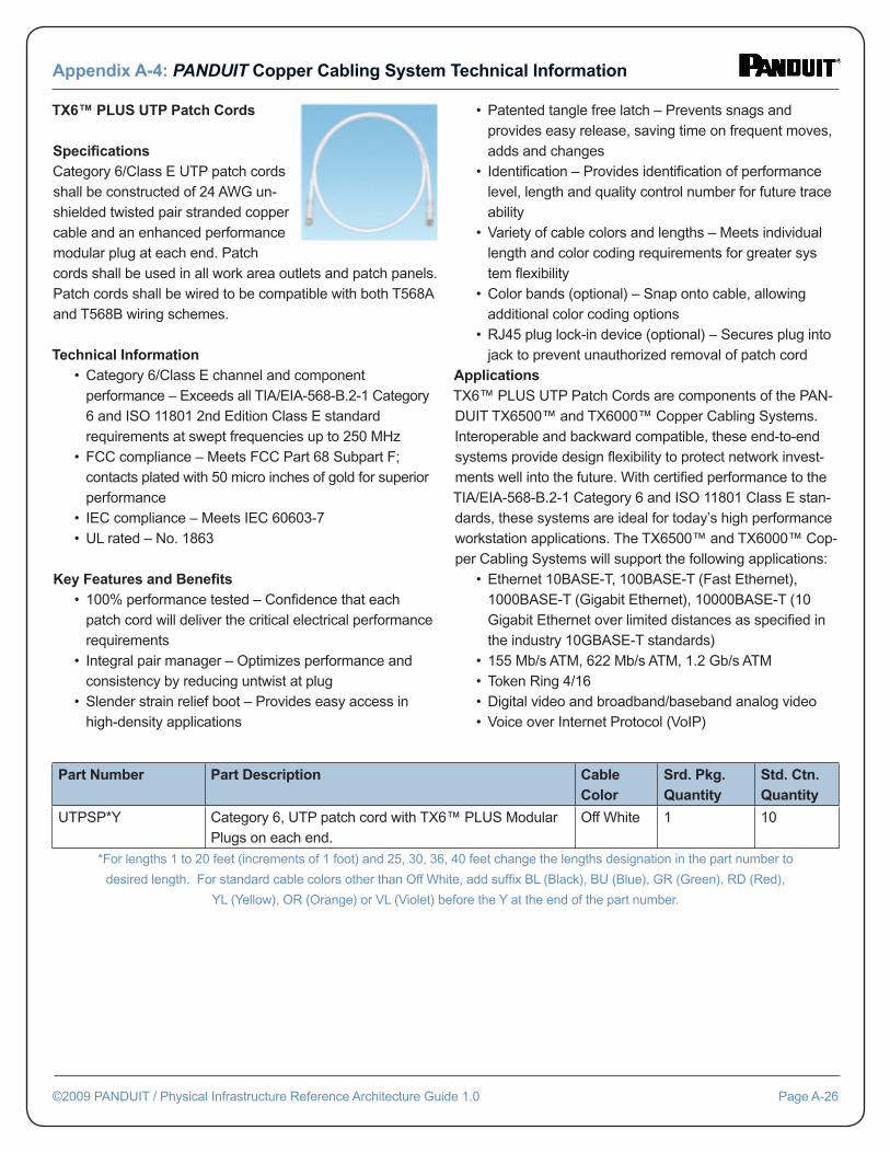
TX6™ PLUS UTP Patch Cords Specifi cationsCategory 6/Class E UTP patch cords shall be constructed of 24 AWG un-shielded twisted pair stranded copper cable and an enhanced performance modular plug at each end. Patch cords shall be used in all work area outlets and patch panels. Patch cords shall be wired to be compatible with both T568A and T568B wiring schemes.
Technical Information • Category 6/Class E channel and component performance – Exceeds all TIA/EIA-568-B.2-1 Category 6 and ISO 11801 2nd Edition Class E standard requirements at swept frequencies up to 250 MHz • FCC compliance – Meets FCC Part 68 Subpart F; contacts plated with 50 micro inches of gold for superior performance • IEC compliance – Meets IEC 60603-7 • UL rated – No. 1863
Key Features and Benefi ts • 100% performance tested – Confi dence that each patch cord will deliver the critical electrical performance requirements • Integral pair manager – Optimizes performance and consistency by reducing untwist at plug • Slender strain relief boot – Provides easy access in high-density applications
• Patented tangle free latch – Prevents snags and provides easy release, saving time on frequent moves, adds and changes • Identifi cation – Provides identifi cation of performance level, length and quality control number for future trace ability • Variety of cable colors and lengths – Meets individual length and color coding requirements for greater sys tem fl exibility • Color bands (optional) – Snap onto cable, allowing additional color coding options • RJ45 plug lock-in device (optional) – Secures plug into jack to prevent unauthorized removal of patch cordApplicationsTX6™ PLUS UTP Patch Cords are components of the PAN-DUIT TX6500™ and TX6000™ Copper Cabling Systems. Interoperable and backward compatible, these end-to-end systems provide design fl exibility to protect network invest-ments well into the future. With certifi ed performance to the TIA/EIA-568-B.2-1 Category 6 and ISO 11801 Class E stan-dards, these systems are ideal for today’s high performance workstation applications. The TX6500™ and TX6000™ Cop-per Cabling Systems will support the following applications: • Ethernet 10BASE-T, 100BASE-T (Fast Ethernet), 1000BASE-T (Gigabit Ethernet), 10000BASE-T (10 Gigabit Ethernet over limited distances as specifi ed in the industry 10GBASE-T standards) • 155 Mb/s ATM, 622 Mb/s ATM, 1.2 Gb/s ATM • Token Ring 4/16 • Digital video and broadband/baseband analog video • Voice over Internet Protocol (VoIP)
Appendix A-4: PANDUIT Copper Cabling System Technical Information
©2009 PANDUIT / Physical Infrastructure Reference Architecture Guide 1.0 Page A-26
Part Number Part Description Cable Color
Srd. Pkg. Quantity
Std. Ctn. Quantity
UTPSP*Y Category 6, UTP patch cord with TX6™ PLUS Modular Plugs on each end.
Off White 1 10
*For lengths 1 to 20 feet (increments of 1 foot) and 25, 30, 36, 40 feet change the lengths designation in the part number to
desired length. For standard cable colors other than Off White, add suffi x BL (Black), BU (Blue), GR (Green), RD (Red),
YL (Yellow), OR (Orange) or VL (Violet) before the Y at the end of the part number.
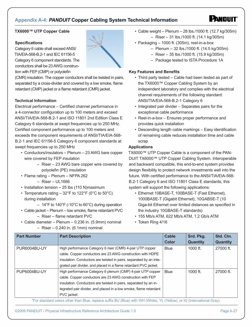
TX6000™ UTP Copper Cable Specifi cationsCategory 6 cable shall exceed ANSI/TIA/EIA-568-B.2-1 and IEC 61156-5 Category 6 component standards. The conductors shall be 23 AWG construc-tion with FEP (CMP) or polyolefi n (CMR) insulation. The copper conductors shall be twisted in pairs, separated by a cross-divider and covered by a low smoke, fl ame retardant (CMP) jacket or a fl ame retardant (CMR) jacket.
Technical InformationElectrical performance – Certifi ed channel performance in a 4-connector confi guration up to 100 meters and exceed ANSI/TIA/EIA-568-B.2-1 and ISO 11801 2nd Edition Class E Category 6 standards at swept frequencies up to 250 MHz. Certifi ed component performance up to 100 meters and exceeds the component requirements of ANSI/TIA/EIA-568-B.2-1 and IEC 61156-5 Category 6 component standards at swept frequencies up to 250 MHz • Conductors/insulators – Plenum – 23 AWG bare copper wire covered by FEP insulation – Riser – 23 AWG bare copper wire covered by polyolefi n (PE) insulation • Flame rating – Plenum – NFPA 262 – Riser – UL1666 • Installation tension – 25 lbs (110 N)maximum • Temperature rating – 32°F to 122°F (0°C to 50°C) during installation – 14°F to 140°F (-10°C to 60°C) during operation • Cable jacket – Plenum – low smoke, fl ame retardant PVC – Riser – fl ame retardant PVC • Cable diameter – Plenum – 0.236 in. (5.9mm) nominal – Riser – 0.240 in. (6.1mm) nominal
• Cable weight – Plenum – 28 lbs./1000 ft. (12.7 kg/305m) – Riser – 31 lbs./1000 ft. (14.1 kg/305m) • Packaging – 1000 ft. (305m), reel-in-a-box – Plenum – 32 lbs./1000 ft. (14.5 kg/305m) – Riser – 35 lbs./1000 ft. (15.9 kg/305m) – Package tested to ISTA Procedure 1A
Key Features and Benefi ts • Third party tested – Cable had been tested as part of the TX6000™ Copper Cabling System by an independent laboratory and complies with the electrical channel requirements of the following standard: ANSI/TIA/EIA-568-B.2-1 Category 6 • Integrated pair divider – Separates pairs for the exceptional cable performance • Reel-in-a-box – Ensures proper performance and provides quick installation • Descending length cable markings – Easy identifi cation of remaining cable reduces installation time and cable scrapApplicationsTX6000™ UTP Copper Cable is a component of the PAN-DUIT TX6000™ UTP Copper Cabling System. Interoperable and backward compatible, this end-to-end system provides design fl exibility to protect network investments well into the future. With certifi ed performance to the ANSI/TIA/EIA-568-B.2-1 Category 6 and ISO 11801 Class E standards, this system will support the following applications: • Ethernet 10BASE-T, 100BASE-T (Fast Ethernet), 1000BASE-T (Gigabit Ethernet), 10GABSE-T (10 Giga-bit Ethernet over limited distances as specifi ed in the industry 10GBASE-T standards) • 155 Mb/s ATM, 622 Mb/s ATM, 1.2 Gb/s ATM • Token Ring 4/16
Appendix A-4: PANDUIT Copper Cabling System Technical Information
©2009 PANDUIT / Physical Infrastructure Reference Architecture Guide 1.0 Page A-27
Part Number Part Description Cable Color
Srd. Pkg. Quantity
Std. Ctn. Quantity
PUR6004BU-UY High performance Category 6 riser (CMR) 4-pair UTP copper
cable. Copper conductors are 23 AWG construction with HDPE
insulation. Conductors are twisted in pairs, separated by an inte-
grated pair divider, and placed in a fl ame retardant PVC jacket.
Blue 1000 ft. 27000 ft.
PUP6004BU-UY High performance Category 6 plenum (CMP) 4-pair UTP copper
cable. Copper conductors are 23 AWG construction with FEP
insulation. Conductors are twisted in pairs, separated by an in-
tegrated pair divider, and placed in a low smoke, fl ame retardant
PVC jacket.
Blue 1000 ft. 27000 ft.
*For standard colors other than Blue, replace suffi x BU (Blue) with WH (White), YL (Yellow), or IG (International Gray).
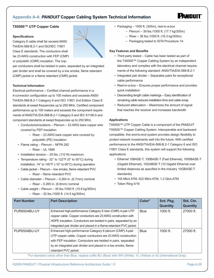
TX6500™ UTP Copper Cable Specifi cations
Category 6 cable shall far exceed ANSI/
TIA/EIA-568-B.2-1 and ISO/IEC 11801
Class E standards. The conductors shall
be 23 AWG construction with FEP (CMP)
or polyolefi n (CMR) insulation. The cop-
per conductors shall be twisted in pairs, separated by an integrated
pair divider and shall be covered by a low smoke, fl ame retardant
(CMP) jacket or a fl ame retardant (CMR) jacket.
Technical Information
Electrical performance – Certifi ed channel performance in a
4-connector confi guration up to 100 meters and exceeds ANSI/
TIA/EIA-568-B.2-1 Category 6 and ISO 11801 2nd Edition Class E
standards at swept frequencies up to 250 MHz. Certifi ed component
performance up to 100 meters and exceeds the component require-
ments of ANSI/TIA.EIA-568-B.2-1 Category 6 and IEC 61156-5 and
component standards at swept frequencies up to 250 MHz.
• Conductors/insulators – Plenum – 23 AWG bare copper wire
covered by FEP insulation
– Riser – 23 AWG bare copper wire covered by
polyolefi n (PE) insulation
• Flame rating – Plenum – NFPA 262
– Riser – UL 1666
• Installation tension – 25 lbs. (110 N) maximum
• Temperature rating - 32° to 122°F (0° to 50°C) during
installation, 14° to 140°F (-10° to 60°C) during operation
• Cable jacket – Plenum – low smoke, fl ame retardant PVC
– Riser – fl ame retardant PVC
• Cable diameter – Plenum – 0.264 in. (6.7mm) nominal
– Riser – 0.265 in. (6.8mm) nominal
• Cable weight – Plenum – 35 lbs./1000 ft. (15.8 kg/305m)
– Riser – 32 lbs./1000 ft. (14.5 kg/305m)
• Packaging – 1000 ft. (305m), reel-in-a-box
– Plenum – 39 lbs./1000 ft. (17.7 kg/305m)
– Riser – 36 lbs./1000 ft. (16.3 kg/305m)
– Packaging tested to ISTA Procedure 1A
Key Features and Benefi ts
• Third party tested – Cable has been tested as part of
the TX6500™ Copper Cabling System by an independent
laboratory and complies with the electrical channel require-
ments of the following standard: ANSI/TIA/EIA-568-B.2-1
• Integrated pair divider – Separates pairs for exceptional
cable performance
• Reel-in-a-box – Ensures proper performance and provides
quick installation
• Descending length cable markings – Easy identifi cation of
remaining cable reduces installation time and cable scrap
• Reduced attenuation – Maximizes the amount of signal
that reaches the receiver and increases bandwidth
Applications
TX6500™ UTP Copper Cable is a component of the PANDUIT
TX6500™ Copper Cabling System. Interoperable and backward
compatible, this end-to-end system provides design fl exibility to
protect network investments well into the future. With certifi ed
performance to the ANSI/TIA/EIA-568-B.2-1 Category 6 and ISO
11801 Class E standards, this system will support the following
applications:
• Ethernet 10BASE-T, 100BASE-T (Fast Ethernet), 1000BASE-T
(Gigabit Ethernet), 10GABSE-T (10 Gigabit Ethernet over
limited distances as specifi ed in the industry 10GBASE-T
standards)
• 155 Mb/s ATM, 622 Mb/s ATM, 1.2 Gb/s ATM
• Token Ring 4/16
Appendix A-4: PANDUIT Copper Cabling System Technical Information
©2009 PANDUIT / Physical Infrastructure Reference Architecture Guide 1.0 Page A-28
Part Number Part Description Color* Srd. Pkg. Quantity
Std. Ctn. Quantity
PUR6504BU-UY Enhanced high-performance Category 6 riser (CMR) 4-pair UTP
copper cable. Copper conductors are 23 AWG construction with
HDPE insulation. Conductors are twisted in pairs, separated by an
integrated pair divider and placed in a fl ame-retardant PVC jacket.
Blue 1000 ft. 27000 ft.
PUP6504BU-UY Enhanced high-performance Category 6 plenum (CMP) 4-pair
UTP copper cable. Copper conductors are 23 AWG construction
with FEP insulation. Conductors are twisted in pairs, separated
by an integrated pair divider and placed in a low smoke, fl ame-
retardant PVC jacket.
Blue 1000 ft. 27000 ft.
*For standard colors other than Blue, replace suffi x BU (Blue) with WH (White), YL (Yellow) or IG (International Gray).
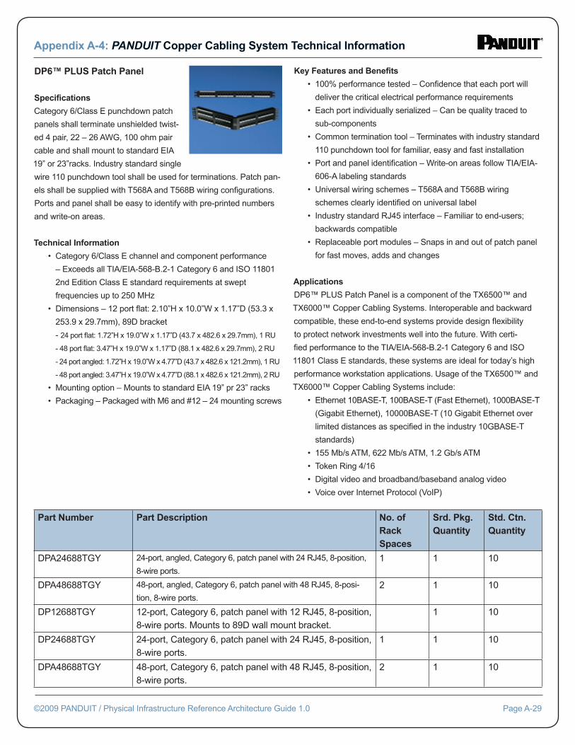
DP6™ PLUS Patch Panel
Specifi cations
Category 6/Class E punchdown patch
panels shall terminate unshielded twist-
ed 4 pair, 22 – 26 AWG, 100 ohm pair
cable and shall mount to standard EIA
19” or 23”racks. Industry standard single
wire 110 punchdown tool shall be used for terminations. Patch pan-
els shall be supplied with T568A and T568B wiring confi gurations.
Ports and panel shall be easy to identify with pre-printed numbers
and write-on areas.
Technical Information
• Category 6/Class E channel and component performance
– Exceeds all TIA/EIA-568-B.2-1 Category 6 and ISO 11801
2nd Edition Class E standard requirements at swept
frequencies up to 250 MHz
• Dimensions – 12 port fl at: 2.10”H x 10.0”W x 1.17”D (53.3 x
253.9 x 29.7mm), 89D bracket
- 24 port fl at: 1.72”H x 19.0”W x 1.17”D (43.7 x 482.6 x 29.7mm), 1 RU
- 48 port fl at: 3.47”H x 19.0”W x 1.17”D (88.1 x 482.6 x 29.7mm), 2 RU
- 24 port angled: 1.72”H x 19.0”W x 4.77”D (43.7 x 482.6 x 121.2mm), 1 RU
- 48 port angled: 3.47”H x 19.0”W x 4.77”D (88.1 x 482.6 x 121.2mm), 2 RU
• Mounting option – Mounts to standard EIA 19” pr 23” racks
• Packaging – Packaged with M6 and #12 – 24 mounting screws
Key Features and Benefi ts
• 100% performance tested – Confi dence that each port will
deliver the critical electrical performance requirements
• Each port individually serialized – Can be quality traced to
sub-components
• Common termination tool – Terminates with industry standard
110 punchdown tool for familiar, easy and fast installation
• Port and panel identifi cation – Write-on areas follow TIA/EIA-
606-A labeling standards
• Universal wiring schemes – T568A and T568B wiring
schemes clearly identifi ed on universal label
• Industry standard RJ45 interface – Familiar to end-users;
backwards compatible
• Replaceable port modules – Snaps in and out of patch panel
for fast moves, adds and changes
Applications
DP6™ PLUS Patch Panel is a component of the TX6500™ and
TX6000™ Copper Cabling Systems. Interoperable and backward
compatible, these end-to-end systems provide design fl exibility
to protect network investments well into the future. With certi-
fi ed performance to the TIA/EIA-568-B.2-1 Category 6 and ISO
11801 Class E standards, these systems are ideal for today’s high
performance workstation applications. Usage of the TX6500™ and
TX6000™ Copper Cabling Systems include:
• Ethernet 10BASE-T, 100BASE-T (Fast Ethernet), 1000BASE-T
(Gigabit Ethernet), 10000BASE-T (10 Gigabit Ethernet over
limited distances as specifi ed in the industry 10GBASE-T
standards)
• 155 Mb/s ATM, 622 Mb/s ATM, 1.2 Gb/s ATM
• Token Ring 4/16
• Digital video and broadband/baseband analog video
• Voice over Internet Protocol (VoIP)
Appendix A-4: PANDUIT Copper Cabling System Technical Information
©2009 PANDUIT / Physical Infrastructure Reference Architecture Guide 1.0 Page A-29
Part Number Part Description No. of Rack Spaces
Srd. Pkg. Quantity
Std. Ctn. Quantity
DPA24688TGY 24-port, angled, Category 6, patch panel with 24 RJ45, 8-position,
8-wire ports.
1 1 10
DPA48688TGY 48-port, angled, Category 6, patch panel with 48 RJ45, 8-posi-
tion, 8-wire ports.
2 1 10
DP12688TGY 12-port, Category 6, patch panel with 12 RJ45, 8-position, 8-wire ports. Mounts to 89D wall mount bracket.
1 10
DP24688TGY 24-port, Category 6, patch panel with 24 RJ45, 8-position, 8-wire ports.
1 1 10
DPA48688TGY 48-port, Category 6, patch panel with 48 RJ45, 8-position, 8-wire ports.
2 1 10
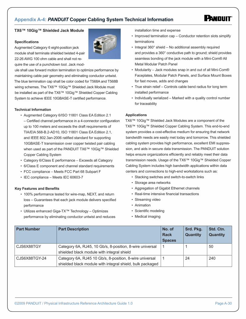
TX6™ 10Gig™ Shielded Jack Module
Specifi cations
Augmented Category 6 eight-position jack
module shall terminate shielded twisted 4-pair
22-26 AWG 100 ohm cable and shall not re-
quire the use of a punchdown tool. Jack mod-
ule shall use forward motion termination to optimize performance by
maintaining cable pair geometry and eliminating conductor untwist.
The blue termination cap shall be color coded for T568A and T568B
wiring schemes. The TX6™ 10Gig™ Shielded Jack Module must
be installed as part of the TX6™ 10Gig™ Shielded Copper Cabling
System to achieve IEEE 10GBASE-T certifi ed performance.
Technical Information
• Augmented Category 6/ISO 11801 Class EA Edition 2.1
– Certifi ed channel performance in a 4-connector confi guration
up to 100 meters and exceeds the draft requirements of
TIA/EIA 568-B.2-AD10, ISO 11801 Class EA Edition 2.1,
and IEEE 802.3an-2006 ratifi ed standard for supporting
10GBASE-T transmission over copper twisted pair cabling
when used as part of the PANDUIT TX6™ 10Gig™ Shielded
Copper Cabling System
• Category 6/Class E performance – Exceeds all Category
• 6/Class E component and channel standard requirements
• FCC compliance – Meets FCC Part 68 Subpart F
• IEC compliance – Meets IEC 60603-7
Key Features and Benefi ts
• 100% performance tested for wire-map, NEXT, and return
loss – Guarantees that each jack module delivers specifi ed
performance
• Utilizes enhanced Giga-TX™ Technology – Optimizes
performance by eliminating conductor untwist and reduces
installation time and expense
• Improved termination cap – Conductor retention slots simplify
terminations
• Integral 360° shield – No additional assembly required
and provides a 360° conductive path to ground; shield provides
seamless bonding of the jack module with a Mini-Com® All
Metal Modular Patch Panel
• Modularity – Jack modules snap in and out of all Mini-Com®
Faceplates, Modular Patch Panels, and Surface Mount Boxes
for fast moves, adds and changes
• True strain relief – Controls cable bend radius for long term
installed performance
• Individually serialized – Marked with a quality control number
for traceability
Applications
TX6™ 10Gig™ Shielded Jack Modules are a component of the
TX6™ 10Gig™ Shielded Copper Cabling System. This end-to-end
system provides a cost-effective medium for ensuring that network
bandwidth needs are easily met today and tomorrow. This shielded
cabling system provides high performance, excellent EMI suppres-
sion, and aids in secure data transmission. The PANDUIT solution
helps ensure organizations effi ciently and reliably meet their data
transmission needs. Usage of the TX6™ 10Gig™ Shielded Copper
Cabling System includes high bandwidth applications within data
centers and connections to high-end workstations such as:
• Stacking switches and switch-to-switch links
• Storage area networks
• Aggregation of Gigabit Ethernet channels
• Real-time intensive fi nancial transactions
• Streaming video
• Animation
• Scientifi c modeling
• Medical imaging
Appendix A-4: PANDUIT Copper Cabling System Technical Information
©2009 PANDUIT / Physical Infrastructure Reference Architecture Guide 1.0 Page A-30
Part Number Part Description No. of Rack Spaces
Srd. Pkg. Quantity
Std. Ctn. Quantity
CJS6X88TGY Category 6A, RJ45, 10 Gb/s, 8-position, 8-wire universal shielded black module with integral shield
1 1 50
CJS6X88TGY-24 Category 6A, RJ45 10 Gb/s, 8-position, 8-wire universal shielded black module with integral shield, bulk packaged
1 24 240
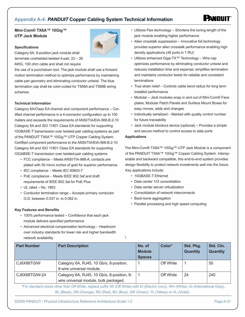
Mini-Com® TX6A™ 10Gig™ UTP Jack Module
Specifi cations
Category 6A, 8-position jack module shall
terminate unshielded twisted 4-pair, 22 – 26
AWG, 100 ohm cable and shall not require
the use of a punchdown tool. The jack module shall use a forward
motion termination method to optimize performance by maintaining
cable pair geometry and eliminating conductor untwist. The blue
termination cap shall be color-coded for T568A and T568B wiring
schemes.
Technical Information
Category 6A/Class EA channel and component performance – Cer-
tifi ed channel performance in a 4-connector confi guration up to 100
meters and exceeds the requirements of ANSI/TIA/EIA-568-B.2-10
Category 6A and ISO 11801 Class EA standards for supporting
10GBASE-T transmission over twisted-pair cabling systems as part
of the PANDUIT TX6A™ 10Gig™ UTP Copper Cabling System.
Certifi ed component performance to the ANSI/TIA/EIA-568-B.2-10
Category 6A and ISO 11801 Class EA standards for supporting
10GABSE-T transmission over twisted-pair cabling systems
• FCC compliance – Meets ANSI/TIA-968-A; contacts are
plated with 50 micro inches of gold for superior performance
• IEC compliance – Meets IEC 60603-7
• PoE compliance – Meets IEEE 802.3af and draft
requirements of IEEE 802.3at for PoE Plus
• UL rated – No. 1863
• Conductor termination range – Accepts primary conductor
O.D. between 0.037 in. to 0.062 in.
Key Features and Benefi ts
• 100% performance tested – Confi dence that each jack
module delivers specifi ed performance
• Advanced electrical compensation technology – Headroom
over industry standards for lower risk and higher bandwidth
network availability
• Utilizes Flex technology – Shortens the tuning length of the
jack module enabling higher performance
• Alien crosstalk suppression – Innovative foil technology
provides superior alien crosstalk performance enabling high
density applications (48 ports in 1 RU)
• Utilizes enhanced Giga-TX™ Technology – Wire cap
optimizes performance by eliminating conductor untwist and
reduces installation time and expense; simplifi es termination
and maintains conductor twists for reliable and consistent
terminations
• True strain relief – Controls cable bend radius for long term
installed performance
• Modular – Jack modules snap in and out of Mini-Com® Face
plates, Modular Patch Panels and Surface Mount Boxes for
easy moves, adds and changes
• Individually serialized – Marked with quality control number
for future traceability
• Jack module blockout device (optional) – Provides a simple
and secure method to control access to data ports
Applications
The Mini-Com® TX6A™ 10Gig™ UTP Jack Module is a component
of the PANDUIT TX6A™ 10Gig™ Copper Cabling System. Interop-
erable and backward compatible, this end-to-end system provides
design fl exibility to protect network investments well into the future.
Key applications include:
• 10GBASE-T Ethernet
• Data center 1/O consolidation
• Data center server virtualization
• Consolidation of network interconnects
• Back-bone aggregation
• Parallel processing and high speed computing
\
Appendix A-4: PANDUIT Copper Cabling System Technical Information
©2009 PANDUIT / Physical Infrastructure Reference Architecture Guide 1.0 Page A-31
Part Number Part Description No. of Module Spaces
Color* Std. Pkg. Quantity
Std. Ctn. Quantity
CJ6X88TGIW Category 6A, RJ45, 10 Gb/s, 8-position, 8-wire universal module.
1 Off White 1 50
CJ6X88TGIW-24 Category 6A, RJ45, 10 Gb/s, 8-position, 8-wire universal module, bulk packaged.
1 Off White 24 240
*For standard colors other than Off White, replace suffi x IW (Off White) with EI (Electric Ivory), WH (White), IG (International Gray),
BL (Black), OR (Orange), RD (Red), BU (Blue), GR (Green), YL (Yellow) or VL (Violet).
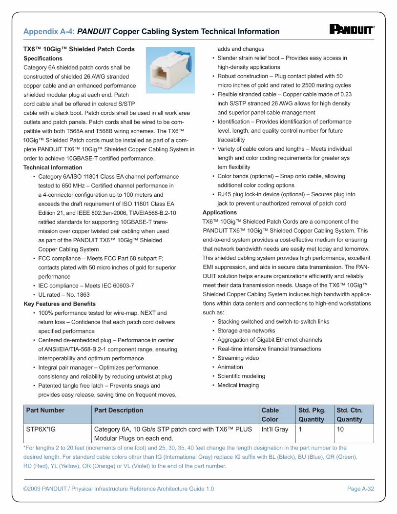
TX6™ 10Gig™ Shielded Patch CordsSpecifi cations
Category 6A shielded patch cords shall be
constructed of shielded 26 AWG stranded
copper cable and an enhanced performance
shielded modular plug at each end. Patch
cord cable shall be offered in colored S/STP
cable with a black boot. Patch cords shall be used in all work area
outlets and patch panels. Patch cords shall be wired to be com-
patible with both T568A and T568B wiring schemes. The TX6™
10Gig™ Shielded Patch cords must be installed as part of a com-
plete PANDUIT TX6™ 10Gig™ Shielded Copper Cabling System in
order to achieve 10GBASE-T certifi ed performance.
Technical Information
• Category 6A/ISO 11801 Class EA channel performance
tested to 650 MHz – Certifi ed channel performance in
a 4-connector confi guration up to 100 meters and
exceeds the draft requirement of ISO 11801 Class EA
Edition 21, and IEEE 802.3an-2006, TIA/EIA568-B.2-10
ratifi ed standards for supporting 10GBASE-T trans-
mission over copper twisted pair cabling when used
as part of the PANDUIT TX6™ 10Gig™ Shielded
Copper Cabling System
• FCC compliance – Meets FCC Part 68 subpart F;
contacts plated with 50 micro inches of gold for superior
performance
• IEC compliance – Meets IEC 60603-7
• UL rated – No. 1863
Key Features and Benefi ts
• 100% performance tested for wire-map, NEXT and
return loss – Confi dence that each patch cord delivers
specifi ed performance
• Centered de-embedded plug – Performance in center
of ANSI/EIA/TIA-568-B.2-1 component range, ensuring
interoperability and optimum performance
• Integral pair manager – Optimizes performance,
consistency and reliability by reducing untwist at plug
• Patented tangle free latch – Prevents snags and
provides easy release, saving time on frequent moves,
adds and changes
• Slender strain relief boot – Provides easy access in
high-density applications
• Robust construction – Plug contact plated with 50
micro inches of gold and rated to 2500 mating cycles
• Flexible stranded cable – Copper cable made of 0.23
inch S/STP stranded 26 AWG allows for high density
and superior panel cable management
• Identifi cation – Provides identifi cation of performance
level, length, and quality control number for future
traceability
• Variety of cable colors and lengths – Meets individual
length and color coding requirements for greater sys
tem fl exibility
• Color bands (optional) – Snap onto cable, allowing
additional color coding options
• RJ45 plug lock-in device (optional) – Secures plug into
jack to prevent unauthorized removal of patch cord
Applications
TX6™ 10Gig™ Shielded Patch Cords are a component of the
PANDUIT TX6™ 10Gig™ Shielded Copper Cabling System. This
end-to-end system provides a cost-effective medium for ensuring
that network bandwidth needs are easily met today and tomorrow.
This shielded cabling system provides high performance, excellent
EMI suppression, and aids in secure data transmission. The PAN-
DUIT solution helps ensure organizations effi ciently and reliably
meet their data transmission needs. Usage of the TX6™ 10Gig™
Shielded Copper Cabling System includes high bandwidth applica-
tions within data centers and connections to high-end workstations
such as:
• Stacking switched and switch-to-switch links
• Storage area networks
• Aggregation of Gigabit Ethernet channels
• Real-time intensive fi nancial transactions
• Streaming video
• Animation
• Scientifi c modeling
• Medical imaging
Appendix A-4: PANDUIT Copper Cabling System Technical Information
©2009 PANDUIT / Physical Infrastructure Reference Architecture Guide 1.0 Page A-32
Part Number Part Description Cable Color
Std. Pkg. Quantity
Std. Ctn. Quantity
STP6X*IG Category 6A, 10 Gb/s STP patch cord with TX6™ PLUS Modular Plugs on each end.
Int’ll Gray 1 10
*For lengths 2 to 20 feet (increments of one foot) and 25, 30, 35, 40 feet change the length designation in the part number to the
desired length. For standard cable colors other than IG (International Gray) replace IG suffi x with BL (Black), BU (Blue), GR (Green),
RD (Red), YL (Yellow), OR (Orange) or VL (Violet) to the end of the part number.
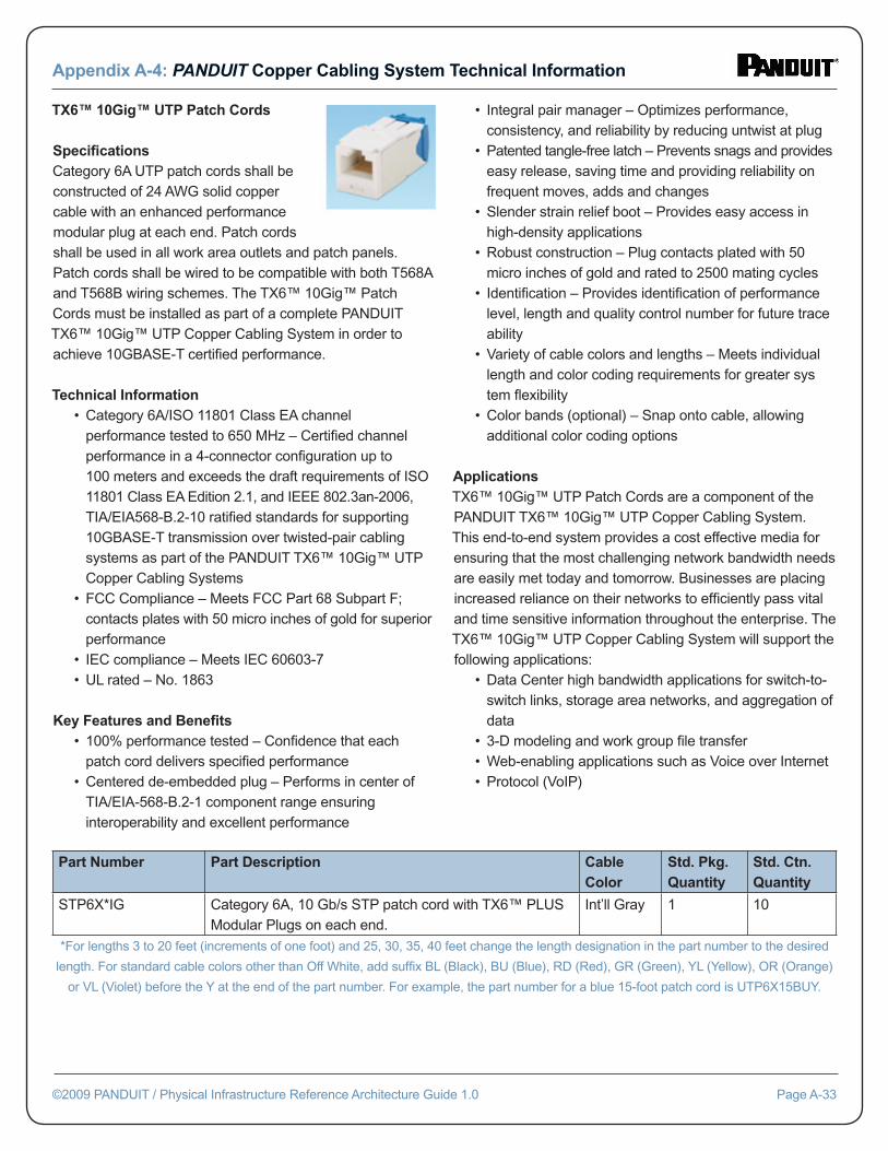
TX6™ 10Gig™ UTP Patch Cords Specifi cationsCategory 6A UTP patch cords shall be constructed of 24 AWG solid copper cable with an enhanced performance modular plug at each end. Patch cords shall be used in all work area outlets and patch panels. Patch cords shall be wired to be compatible with both T568A and T568B wiring schemes. The TX6™ 10Gig™ Patch Cords must be installed as part of a complete PANDUIT TX6™ 10Gig™ UTP Copper Cabling System in order to achieve 10GBASE-T certifi ed performance.
Technical Information • Category 6A/ISO 11801 Class EA channel performance tested to 650 MHz – Certifi ed channel performance in a 4-connector confi guration up to 100 meters and exceeds the draft requirements of ISO 11801 Class EA Edition 2.1, and IEEE 802.3an-2006, TIA/EIA568-B.2-10 ratifi ed standards for supporting 10GBASE-T transmission over twisted-pair cabling systems as part of the PANDUIT TX6™ 10Gig™ UTP Copper Cabling Systems • FCC Compliance – Meets FCC Part 68 Subpart F; contacts plates with 50 micro inches of gold for superior performance • IEC compliance – Meets IEC 60603-7 • UL rated – No. 1863
Key Features and Benefi ts • 100% performance tested – Confi dence that each patch cord delivers specifi ed performance • Centered de-embedded plug – Performs in center of TIA/EIA-568-B.2-1 component range ensuring interoperability and excellent performance
• Integral pair manager – Optimizes performance, consistency, and reliability by reducing untwist at plug • Patented tangle-free latch – Prevents snags and provides easy release, saving time and providing reliability on frequent moves, adds and changes • Slender strain relief boot – Provides easy access in high-density applications • Robust construction – Plug contacts plated with 50 micro inches of gold and rated to 2500 mating cycles • Identifi cation – Provides identifi cation of performance level, length and quality control number for future trace ability • Variety of cable colors and lengths – Meets individual length and color coding requirements for greater sys tem fl exibility • Color bands (optional) – Snap onto cable, allowing additional color coding options
ApplicationsTX6™ 10Gig™ UTP Patch Cords are a component of the PANDUIT TX6™ 10Gig™ UTP Copper Cabling System. This end-to-end system provides a cost effective media for ensuring that the most challenging network bandwidth needs are easily met today and tomorrow. Businesses are placing increased reliance on their networks to effi ciently pass vital and time sensitive information throughout the enterprise. The TX6™ 10Gig™ UTP Copper Cabling System will support the following applications: • Data Center high bandwidth applications for switch-to- switch links, storage area networks, and aggregation of data • 3-D modeling and work group fi le transfer • Web-enabling applications such as Voice over Internet • Protocol (VoIP)
Appendix A-4: PANDUIT Copper Cabling System Technical Information
©2009 PANDUIT / Physical Infrastructure Reference Architecture Guide 1.0 Page A-33
Part Number Part Description Cable Color
Std. Pkg. Quantity
Std. Ctn. Quantity
STP6X*IG Category 6A, 10 Gb/s STP patch cord with TX6™ PLUS Modular Plugs on each end.
Int’ll Gray 1 10
*For lengths 3 to 20 feet (increments of one foot) and 25, 30, 35, 40 feet change the length designation in the part number to the desired
length. For standard cable colors other than Off White, add suffi x BL (Black), BU (Blue), RD (Red), GR (Green), YL (Yellow), OR (Orange)
or VL (Violet) before the Y at the end of the part number. For example, the part number for a blue 15-foot patch cord is UTP6X15BUY.
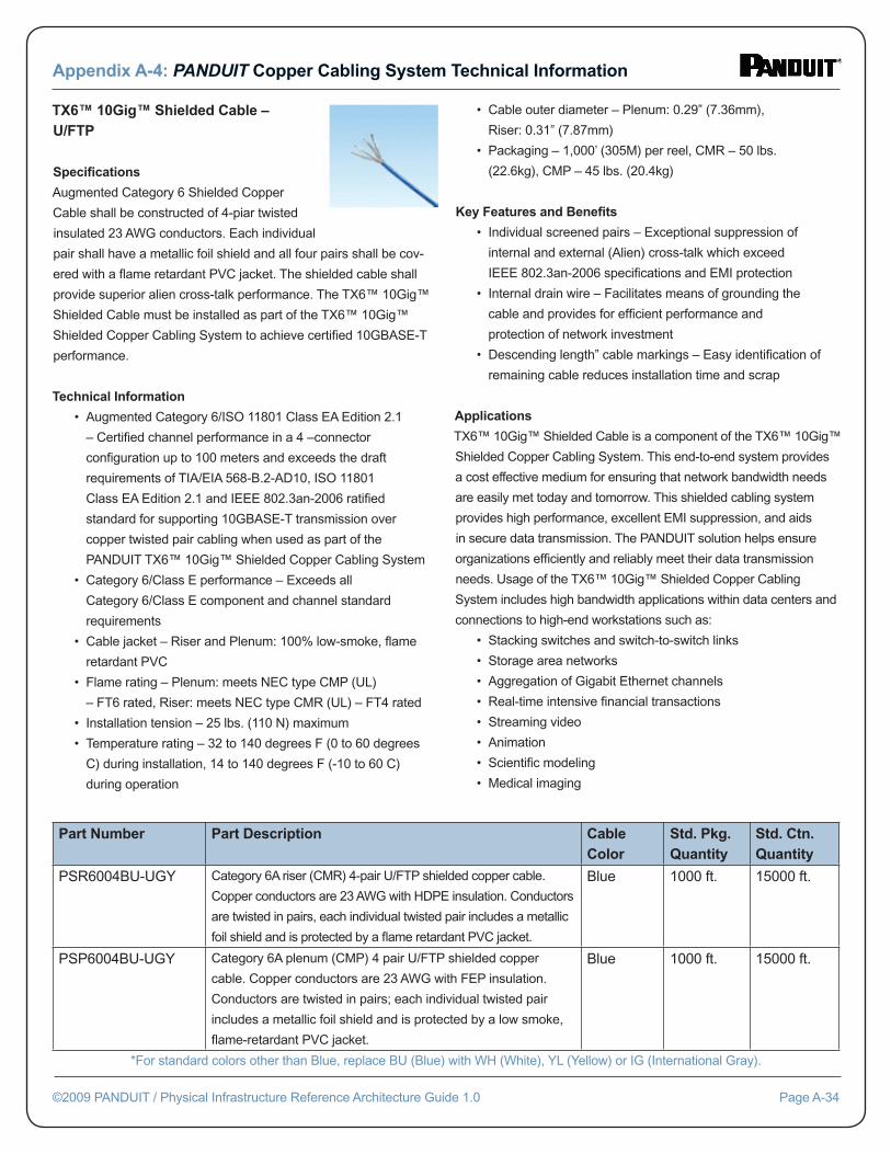
TX6™ 10Gig™ Shielded Cable – U/FTP Specifi cations
Augmented Category 6 Shielded Copper
Cable shall be constructed of 4-piar twisted
insulated 23 AWG conductors. Each individual
pair shall have a metallic foil shield and all four pairs shall be cov-
ered with a fl ame retardant PVC jacket. The shielded cable shall
provide superior alien cross-talk performance. The TX6™ 10Gig™
Shielded Cable must be installed as part of the TX6™ 10Gig™
Shielded Copper Cabling System to achieve certifi ed 10GBASE-T
performance.
Technical Information
• Augmented Category 6/ISO 11801 Class EA Edition 2.1
– Certifi ed channel performance in a 4 –connector
confi guration up to 100 meters and exceeds the draft
requirements of TIA/EIA 568-B.2-AD10, ISO 11801
Class EA Edition 2.1 and IEEE 802.3an-2006 ratifi ed
standard for supporting 10GBASE-T transmission over
copper twisted pair cabling when used as part of the
PANDUIT TX6™ 10Gig™ Shielded Copper Cabling System
• Category 6/Class E performance – Exceeds all
Category 6/Class E component and channel standard
requirements
• Cable jacket – Riser and Plenum: 100% low-smoke, fl ame
retardant PVC
• Flame rating – Plenum: meets NEC type CMP (UL)
– FT6 rated, Riser: meets NEC type CMR (UL) – FT4 rated
• Installation tension – 25 lbs. (110 N) maximum
• Temperature rating – 32 to 140 degrees F (0 to 60 degrees
C) during installation, 14 to 140 degrees F (-10 to 60 C)
during operation
• Cable outer diameter – Plenum: 0.29” (7.36mm),
Riser: 0.31” (7.87mm)
• Packaging – 1,000’ (305M) per reel, CMR – 50 lbs.
(22.6kg), CMP – 45 lbs. (20.4kg)
Key Features and Benefi ts
• Individual screened pairs – Exceptional suppression of
internal and external (Alien) cross-talk which exceed
IEEE 802.3an-2006 specifi cations and EMI protection
• Internal drain wire – Facilitates means of grounding the
cable and provides for effi cient performance and
protection of network investment
• Descending length” cable markings – Easy identifi cation of
remaining cable reduces installation time and scrap
Applications
TX6™ 10Gig™ Shielded Cable is a component of the TX6™ 10Gig™
Shielded Copper Cabling System. This end-to-end system provides
a cost effective medium for ensuring that network bandwidth needs
are easily met today and tomorrow. This shielded cabling system
provides high performance, excellent EMI suppression, and aids
in secure data transmission. The PANDUIT solution helps ensure
organizations effi ciently and reliably meet their data transmission
needs. Usage of the TX6™ 10Gig™ Shielded Copper Cabling
System includes high bandwidth applications within data centers and
connections to high-end workstations such as:
• Stacking switches and switch-to-switch links
• Storage area networks
• Aggregation of Gigabit Ethernet channels
• Real-time intensive fi nancial transactions
• Streaming video
• Animation
• Scientifi c modeling
• Medical imaging
Appendix A-4: PANDUIT Copper Cabling System Technical Information
©2009 PANDUIT / Physical Infrastructure Reference Architecture Guide 1.0 Page A-34
Part Number Part Description Cable Color
Std. Pkg. Quantity
Std. Ctn. Quantity
PSR6004BU-UGY Category 6A riser (CMR) 4-pair U/FTP shielded copper cable.
Copper conductors are 23 AWG with HDPE insulation. Conductors
are twisted in pairs, each individual twisted pair includes a metallic
foil shield and is protected by a fl ame retardant PVC jacket.
Blue 1000 ft. 15000 ft.
PSP6004BU-UGY Category 6A plenum (CMP) 4 pair U/FTP shielded copper
cable. Copper conductors are 23 AWG with FEP insulation.
Conductors are twisted in pairs; each individual twisted pair
includes a metallic foil shield and is protected by a low smoke,
fl ame-retardant PVC jacket.
Blue 1000 ft. 15000 ft.
*For standard colors other than Blue, replace BU (Blue) with WH (White), YL (Yellow) or IG (International Gray).
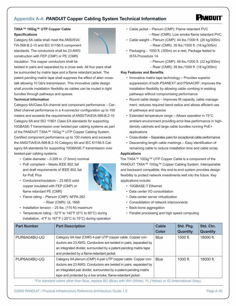
TX6A™ 10Gig™ UTP Copper Cable
Specifi cations
Category 6A cable shall meet the ANSI/EIA/
TIA-568-B.2-10 and IEC 61156-5 component
standards. The conductors shall be 23 AWG
construction with FEP (CMP) or PE (CMR)
insulation. The copper conductors shall be
twisted in pairs and separated by a cross web. All four pairs shall
be surrounded by matrix tape and a fl ame retardant jacket. The
patent pending matrix tape shall suppress the effect of alien cross-
talk allowing 10 Gb/s transmission. This innovative cable design
shall provide installation fl exibility as cables can be routed in tight
bundles through pathways and spaces.
Technical Information
Category 6A/Class EA channel and component performance – Cer-
tifi ed channel performance in a 4-connector confi guration up to 100
meters and exceeds the requirements of ANSI/TIA/EIA-568-B.2-10
Category 6A and ISO 11801 Class EA standards for supporting
10GBASE-T transmission over twisted-pair cabling systems as part
of the PANDUIT TX6A™ 10Gig™ UTP Copper Cabling System.
Certifi ed component performance up to 100 meters and exceeds
the ANSI/TIA/EIA-568-B.2-10 Category 6A and IEC 61156-5 Cat-
egory 6A standards for supporting 10GBASE-T transmission over
twisted-pair cabling systems.
• Cable diameter – 0.295 in. (7.5mm) nominal
• PoE compliant – Meets IEEE 802.3af
and draft requirements of IEEE 802.3at
for PoE Plus
• Conductors/insulators – 23 AEG solid
copper insulated with FEP (CMP) or
fl ame retardant PE (CMR)
• Flame rating – Plenum (CMP): NFPA 262
– Riser (CMR): UL 1666
• Installation tension – 25 lbs. (110 N) maximum
• Temperature rating - 32°F to 140°F (0°C to 60°C) during
installation, -4°F to 167°F (-20°C to 75°C) during operation
• Cable jacket – Plenum (CMP): Flame retardant PVC
– Riser (CMR): Low smoke fl ame retardant PVC
• Cable weight – Plenum (CMP): 44 lbs./1000 ft. (20 kg/305m)
– Riser (CMR): 35 lbs./1000 ft. (16 kg/305m)
• Packaging – 1000 ft. (305m) on a reel, Package tested to
ISTA Procedure 1A
– Plenum (CMP): 48 lbs./1000 ft. (22 kg/305m)
– Riser (CMR): 39 lbs./1000 ft. (18 kg/305m)
Key Features and Benefi ts
• Innovative matrix tape technology – Provides superior
suppression of both PSANEXT and PSAACRF; improves the
installation fl exibility by allowing cable combing in existing
pathways without compromising performance
• Round cable design – Improves fi ll capacity, cable manage-
ment, reduces required bend radius and allows effi cient use
of pathways and spaces
• Extended temperature range – Allows operation in 75°C
ambient environment providing error-free performance in high-
density cabinets and large cable bundles running PoE+
applications
• Cross-divider – Separates pairs for exceptional cable performance
• Descending length cable markings – Easy identifi cation of
remaining cable to reduce installation time and cable scrap
Applications
The TX6A™ 10Gig™ UTP Copper Cable is a component of the
PANDUIT TX6A™ 10Gig™ Copper Cabling System. Interoperable
and backward compatible, this end-to-end system provides design
fl exibility to protect network investments well into the future. Key
applications include:
• 10GBASE-T Ethernet
• Data center I/O consolidation
• Data center server virtualization
• Consolidation of network interconnects
• Back-bone aggregation
• Parallel processing and high speed computing
Appendix A-4: PANDUIT Copper Cabling System Technical Information
©2009 PANDUIT / Physical Infrastructure Reference Architecture Guide 1.0 Page A-35
Part Number Part Description Cable Color
Std. Pkg. Quantity
Std. Ctn. Quantity
PUR6A04BU-UG Category 6A riser (CMR) 4-pair UTP copper cable. Copper con-
ductors are 23 AWG. Conductors are twisted in pairs, separated by
an integrated divider, surrounded by a patent-pending matrix tape
and protected by a fl ame-retardant jacket.
Blue 1000 ft. 18000 ft.
PUP6A04BU-UG Category 6A plenum (CMP) 4-pair UTP copper cable. Copper con-
ductors are 23 AWG. Conductors are twisted in pairs, separated by
an integrated pair divider, surrounded by a patent-pending matrix
tape and protected by a low smoke, fl ame-retardant jacket.
Blue 1000 ft. 18000 ft.
*For standard colors other than Blue, replace BU (Blue) with WH (White), YL (Yellow) or IG (International Gray).
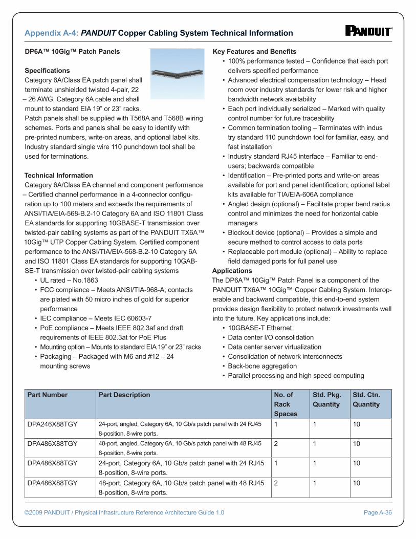
DP6A™ 10Gig™ Patch Panels Specifi cationsCategory 6A/Class EA patch panel shall terminate unshielded twisted 4-pair, 22
– 26 AWG, Category 6A cable and shall mount to standard EIA 19” or 23” racks. Patch panels shall be supplied with T568A and T568B wiring schemes. Ports and panels shall be easy to identify with pre-printed numbers, write-on areas, and optional label kits. Industry standard single wire 110 punchdown tool shall be used for terminations.
Technical InformationCategory 6A/Class EA channel and component performance – Certifi ed channel performance in a 4-connector confi gu-ration up to 100 meters and exceeds the requirements of ANSI/TIA/EIA-568-B.2-10 Category 6A and ISO 11801 Class EA standards for supporting 10GBASE-T transmission over twisted-pair cabling systems as part of the PANDUIT TX6A™ 10Gig™ UTP Copper Cabling System. Certifi ed component performance to the ANSI/TIA/EIA-568-B.2-10 Category 6A and ISO 11801 Class EA standards for supporting 10GAB-SE-T transmission over twisted-pair cabling systems • UL rated – No.1863 • FCC compliance – Meets ANSI/TIA-968-A; contacts are plated with 50 micro inches of gold for superior performance • IEC compliance – Meets IEC 60603-7 • PoE compliance – Meets IEEE 802.3af and draft requirements of IEEE 802.3at for PoE Plus • Mounting option – Mounts to standard EIA 19” or 23” racks • Packaging – Packaged with M6 and #12 – 24 mounting screws
Key Features and Benefi ts • 100% performance tested – Confi dence that each port delivers specifi ed performance • Advanced electrical compensation technology – Head room over industry standards for lower risk and higher bandwidth network availability • Each port individually serialized – Marked with quality control number for future traceability • Common termination tooling – Terminates with indus try standard 110 punchdown tool for familiar, easy, and fast installation • Industry standard RJ45 interface – Familiar to end- users; backwards compatible • Identifi cation – Pre-printed ports and write-on areas available for port and panel identifi cation; optional label kits available for TIA/EIA-606A compliance • Angled design (optional) – Facilitate proper bend radius control and minimizes the need for horizontal cable managers • Blockout device (optional) – Provides a simple and secure method to control access to data ports • Replaceable port module (optional) – Ability to replace fi eld damaged ports for full panel use ApplicationsThe DP6A™ 10Gig™ Patch Panel is a component of the PANDUIT TX6A™ 10Gig™ Copper Cabling System. Interop-erable and backward compatible, this end-to-end system provides design fl exibility to protect network investments well into the future. Key applications include: • 10GBASE-T Ethernet • Data center I/O consolidation • Data center server virtualization • Consolidation of network interconnects • Back-bone aggregation • Parallel processing and high speed computing
Appendix A-4: PANDUIT Copper Cabling System Technical Information
©2009 PANDUIT / Physical Infrastructure Reference Architecture Guide 1.0 Page A-36
Part Number Part Description No. of Rack Spaces
Std. Pkg. Quantity
Std. Ctn. Quantity
DPA246X88TGY 24-port, angled, Category 6A, 10 Gb/s patch panel with 24 RJ45
8-position, 8-wire ports.
1 1 10
DPA486X88TGY 48-port, angled, Category 6A, 10 Gb/s patch panel with 48 RJ45
8-position, 8-wire ports.
2 1 10
DPA486X88TGY 24-port, Category 6A, 10 Gb/s patch panel with 24 RJ45 8-position, 8-wire ports.
1 1 10
DPA486X88TGY 48-port, Category 6A, 10 Gb/s patch panel with 48 RJ45 8-position, 8-wire ports.
2 1 10
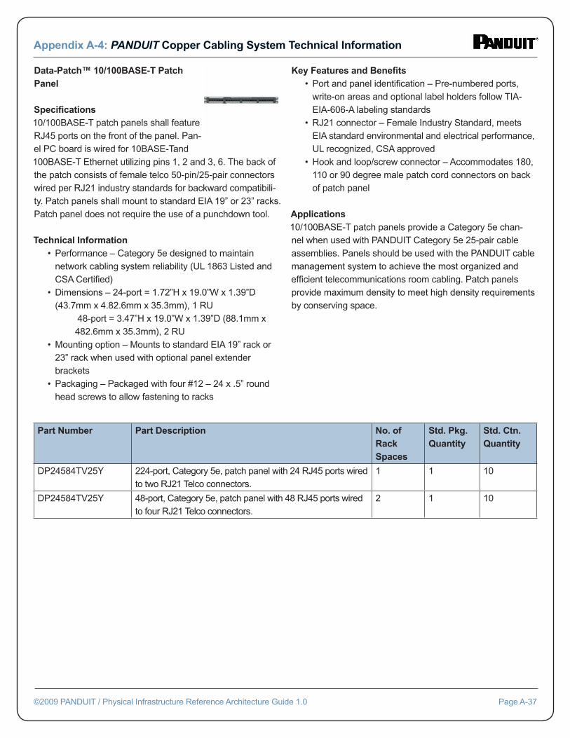
Data-Patch™ 10/100BASE-T Patch Panel Specifi cations10/100BASE-T patch panels shall feature RJ45 ports on the front of the panel. Pan-el PC board is wired for 10BASE-Tand 100BASE-T Ethernet utilizing pins 1, 2 and 3, 6. The back of the patch consists of female telco 50-pin/25-pair connectors wired per RJ21 industry standards for backward compatibili-ty. Patch panels shall mount to standard EIA 19” or 23” racks. Patch panel does not require the use of a punchdown tool.
Technical Information • Performance – Category 5e designed to maintain network cabling system reliability (UL 1863 Listed and CSA Certifi ed) • Dimensions – 24-port = 1.72”H x 19.0”W x 1.39”D (43.7mm x 4.82.6mm x 35.3mm), 1 RU 48-port = 3.47”H x 19.0”W x 1.39”D (88.1mm x 482.6mm x 35.3mm), 2 RU • Mounting option – Mounts to standard EIA 19” rack or 23” rack when used with optional panel extender brackets • Packaging – Packaged with four #12 – 24 x .5” round head screws to allow fastening to racks
Key Features and Benefi ts • Port and panel identifi cation – Pre-numbered ports, write-on areas and optional label holders follow TIA- EIA-606-A labeling standards • RJ21 connector – Female Industry Standard, meets EIA standard environmental and electrical performance, UL recognized, CSA approved • Hook and loop/screw connector – Accommodates 180, 110 or 90 degree male patch cord connectors on back of patch panel
Applications10/100BASE-T patch panels provide a Category 5e chan-nel when used with PANDUIT Category 5e 25-pair cable assemblies. Panels should be used with the PANDUIT cable management system to achieve the most organized and effi cient telecommunications room cabling. Patch panels provide maximum density to meet high density requirements by conserving space.
Appendix A-4: PANDUIT Copper Cabling System Technical Information
©2009 PANDUIT / Physical Infrastructure Reference Architecture Guide 1.0 Page A-37
Part Number Part Description No. of Rack Spaces
Std. Pkg. Quantity
Std. Ctn. Quantity
DP24584TV25Y 224-port, Category 5e, patch panel with 24 RJ45 ports wired to two RJ21 Telco connectors.
1 1 10
DP24584TV25Y 48-port, Category 5e, patch panel with 48 RJ45 ports wired to four RJ21 Telco connectors.
2 1 10
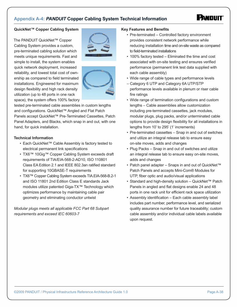
QuickNet™ Copper Cabling System The PANDUIT QuickNet™ Copper Cabling System provides a custom, pre-terminated cabling solution which meets unique requirements. Fast and simple to install, the system enables quick network deployment, increased reliability, and lowest total cost of own-ership as compared to fi eld terminated installations. Engineered for maximum design fl exibility and high rack density utilization (up to 48 ports in one rack space), the system offers 100% factory tested pre-terminated cable assemblies in custom lengths and confi gurations. QuickNet™ Angled and Flat Patch Panels accept QuickNet™ Pre-Terminated Cassettes, Patch Panel Adapters, and Blacks, which snap in and out, with one hand, for quick installation.
Technical Information • Each QuickNet™ Cable Assembly is factory tested to electrical permanent link specifi cations • TX6™ 10Gig™ Copper Cabling System exceeds draft requirements of TIA/EIA-568-2-AD10, ISO 110801 Class EA Edition 2.1 and IEEE 802.3an ratifi ed standard for supporting 10GBASE-T requirements • TX6™ Copper Cabling System exceeds TIA.EIA-568-B.2-1 and ISO 11801 2nd Edition Class E standards Jack modules utilize patented Giga-TX™ Technology which optimizes performance by maintaining cable pair geometry and eliminating conductor untwist
Modular plugs meets all applicable FCC Part 68 Subpart requirements and exceed IEC 60603-7
Key Features and Benefi ts • Pre-terminated – Controlled factory environment provides consistent network performance while reducing installation time and on-site waste as compared to fi eld-terminated installations • 100% factory tested – Eliminated the time and cost associated with on-site testing and ensures verifi ed performance (permanent link test data supplied with each cable assembly) • Wide range of cable types and performance levels – Category 6 UTP and Category 6A UTP/STP performance levels available in plenum or riser cable fi re ratings • Wide range of termination confi gurations and custom lengths – Cable assemblies allow customization including pre-terminated cassettes, jack modules, modular plugs, plug packs, and/or unterminated cable options to provide design fl exibility for all installations in lengths from 10’ to 295’ (1’ increments) • Pre-terminated cassettes – Snap in and out of switches and utilize an integral release tab to ensure easy on-site moves, adds and changes • Plug Packs – Snap in and out of switches and utilize an integral release tab to ensure easy on-site moves, adds and changes • Patch panel adapter – Snaps in and out of QuickNet™ Patch Panels and accepts Mini-Com® Modules for UTP, fi ber optic and audio/visual applications • Standard and high-density solution – QuickNet™ Patch Panels in angled and fl at designs enable 24 and 48 ports in one rack unit for effi cient rack space utilization • Assembly identifi cation – Each cable assembly label includes part number, performance level, and serialized quality assurance number for future traceability; custom cable assembly and/or individual cable labels available upon request.
Appendix A-4: PANDUIT Copper Cabling System Technical Information
©2009 PANDUIT / Physical Infrastructure Reference Architecture Guide 1.0 Page A-38
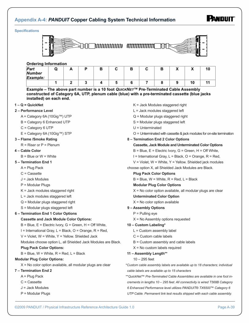
1 – Q = QuickNet
2 – Performance Level
A = Category 6A (10Gig™) UTP
B = Category 6 Enhanced UTP
C = Category 6 UTP
E = Category 6A (10Gig™) STP
3 – Flame /Smoke Rating
R = Riser or P = Plenum
4 – Cable Color
B = Blue or W = White
5 – Termination End 1
A = Plug Pack
C = Cassette
J = Jack Modules
P = Modular Plugs
K = Jack modules staggered right
L = Jack modules staggered left
Q = Modular plugs staggered right
S = Modular plugs staggered left
6 – Termination End 1 Color Options
Cassette and Jack Module Color Options:
B = Blue, E = Electric Ivory, G = Green, H = Off White,
I = International Gray, L = Black, O = Orange, R = Red,
V = Violet, W = White, Y = Yellow. Shielded Jack
Modules choose option L, all Shielded Jack Modules are Black.
Plug Pack Color Options:
B = Blue, W = White, R = Red, L = Black
Modular Plug Color Options:
X = No color option available, all modular plugs are clear
7 – Termination End 2
A = Plug Pack
C = Cassette
J = Jack Modules
P = Modular Plugs
K = Jack Modules staggered right
L = Jack modules staggered left
Q = Modular plugs staggered right
S = Modular plugs staggered left
U = Unterminated
O = Unterminated with cassette & jack modules for on-site termination
8 – Termination End 2 Color Options
Cassette, Jack Module and Unterminated Color Options
B = Blue, E = Electric Ivory, G = Green, H = Off White,
I = International Gray, L = Black, O = Orange, R = Red,
V = Violet, W = White, Y = Yellow. Shielded jack modules
choose option X, all Shielded Jack Modules are Black.
Plug Pack Color Options
B = Blue, W = White, R = Red, L = Black
Modular Plug Color Options
X = No color option available, all modular plugs are clear
Unterminated Color Option
X = No color option available
9 – Assembly Options
P = Pulling eye
X = No Assembly options requested
10 – Custom Labeling*
L = Custom assembly label
C = Custom cable labels
B = Custom assembly and cable labels
X = No custom labels required
11 – Assembly Length**
10 – 295 feet
*Custom cable assembly labels are available up to 18 characters; individual
cable labels are available up to 15 characters
**QuickNet™ Pre-Terminated Cable Assemblies are available in one foot in-
crements in lengths 10 – 295 feet. All connectivity is wired T568B Category
6 Enhanced Performance level utilizes PANDUIT® TX6500™ Category 6
UTP Cable. Permanent link test results shipped with each cable assembly.
Appendix A-4: PANDUIT Copper Cabling System Technical Information
©2009 PANDUIT / Physical Infrastructure Reference Architecture Guide 1.0 Page A-39
Specifi cations
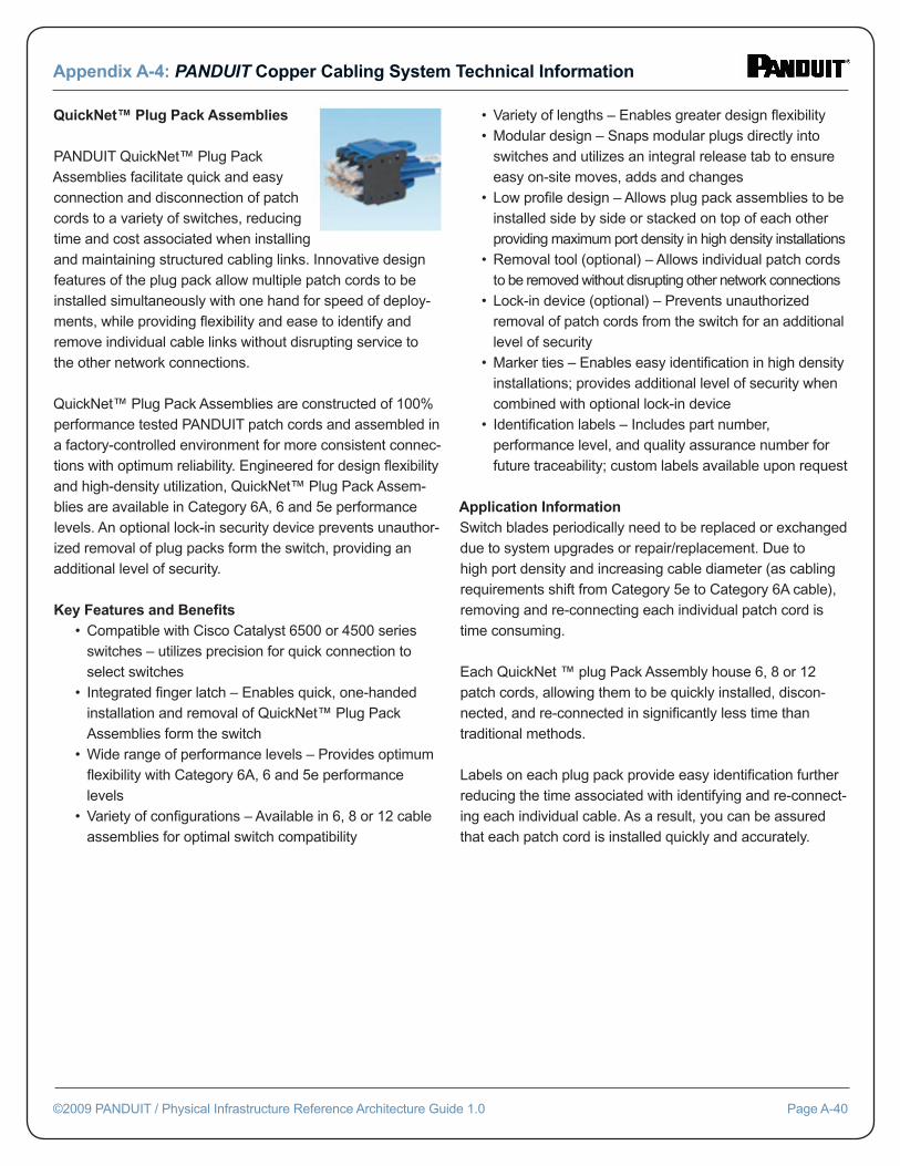
QuickNet™ Plug Pack Assemblies PANDUIT QuickNet™ Plug Pack Assemblies facilitate quick and easy connection and disconnection of patch cords to a variety of switches, reducing time and cost associated when installing and maintaining structured cabling links. Innovative design features of the plug pack allow multiple patch cords to be installed simultaneously with one hand for speed of deploy-ments, while providing fl exibility and ease to identify and remove individual cable links without disrupting service to the other network connections.
QuickNet™ Plug Pack Assemblies are constructed of 100% performance tested PANDUIT patch cords and assembled in a factory-controlled environment for more consistent connec-tions with optimum reliability. Engineered for design fl exibility and high-density utilization, QuickNet™ Plug Pack Assem-blies are available in Category 6A, 6 and 5e performance levels. An optional lock-in security device prevents unauthor-ized removal of plug packs form the switch, providing an additional level of security.
Key Features and Benefi ts • Compatible with Cisco Catalyst 6500 or 4500 series switches – utilizes precision for quick connection to select switches • Integrated fi nger latch – Enables quick, one-handed installation and removal of QuickNet™ Plug Pack Assemblies form the switch • Wide range of performance levels – Provides optimum fl exibility with Category 6A, 6 and 5e performance levels • Variety of confi gurations – Available in 6, 8 or 12 cable assemblies for optimal switch compatibility
• Variety of lengths – Enables greater design fl exibility • Modular design – Snaps modular plugs directly into switches and utilizes an integral release tab to ensure easy on-site moves, adds and changes • Low profi le design – Allows plug pack assemblies to be installed side by side or stacked on top of each other providing maximum port density in high density installations • Removal tool (optional) – Allows individual patch cords to be removed without disrupting other network connections • Lock-in device (optional) – Prevents unauthorized removal of patch cords from the switch for an additional level of security • Marker ties – Enables easy identifi cation in high density installations; provides additional level of security when combined with optional lock-in device • Identifi cation labels – Includes part number, performance level, and quality assurance number for future traceability; custom labels available upon request
Application InformationSwitch blades periodically need to be replaced or exchanged due to system upgrades or repair/replacement. Due to high port density and increasing cable diameter (as cabling requirements shift from Category 5e to Category 6A cable), removing and re-connecting each individual patch cord is time consuming.
Each QuickNet ™ plug Pack Assembly house 6, 8 or 12 patch cords, allowing them to be quickly installed, discon-nected, and re-connected in signifi cantly less time than traditional methods.
Labels on each plug pack provide easy identifi cation further reducing the time associated with identifying and re-connect-ing each individual cable. As a result, you can be assured that each patch cord is installed quickly and accurately.
Appendix A-4: PANDUIT Copper Cabling System Technical Information
©2009 PANDUIT / Physical Infrastructure Reference Architecture Guide 1.0 Page A-40
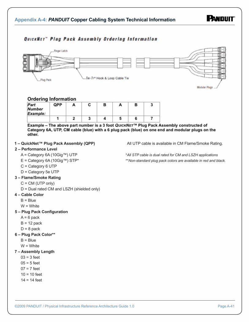
1 – QuickNet™ Plug Pack Assembly (QPP)2 – Performance Level A = Category 6A (10Gig™) UTP E = Category 6A (10Gig™) STP* C = Category 6 UTP D = Category 5e UTP3 – Flame/Smoke Rating C = CM (UTP only) D = Dual rated CM and LSZH (shielded only)4 – Cable Color B = Blue W = White5 – Plug Pack Confi guration A = 6 pack B = 12 pack D = 8 pack6 – Plug Pack Color** B = Blue W = White7 – Assembly Length 03 = 3 feet 05 = 5 feet 07 = 7 feet 10 = 10 feet 14 = 14 feet
All UTP cable is available in CM Flame/Smoke Rating.
*All STP cable is dual rated for CM and LSZH applications
**Non-standard plug pack colors are available in red and black.
Appendix A-4: PANDUIT Copper Cabling System Technical Information
©2009 PANDUIT / Physical Infrastructure Reference Architecture Guide 1.0 Page A-41
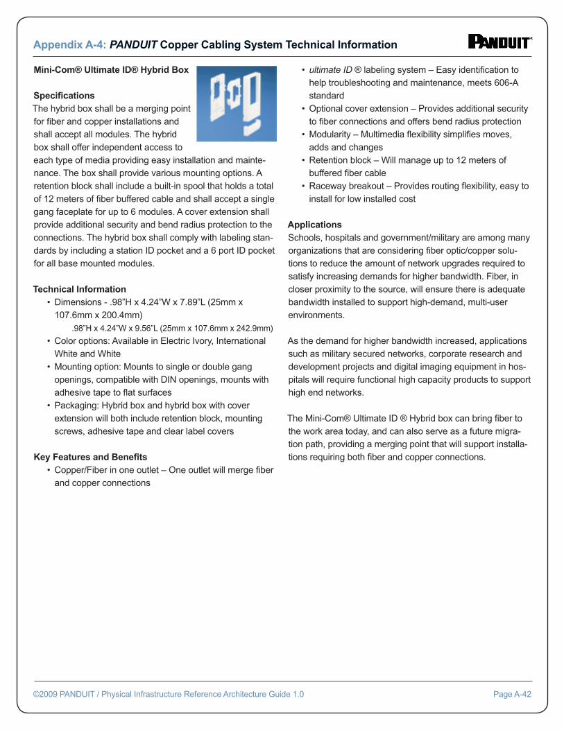
Mini-Com® Ultimate ID® Hybrid Box Specifi cationsThe hybrid box shall be a merging point for fi ber and copper installations and shall accept all modules. The hybrid box shall offer independent access to each type of media providing easy installation and mainte-nance. The box shall provide various mounting options. A retention block shall include a built-in spool that holds a total of 12 meters of fi ber buffered cable and shall accept a single gang faceplate for up to 6 modules. A cover extension shall provide additional security and bend radius protection to the connections. The hybrid box shall comply with labeling stan-dards by including a station ID pocket and a 6 port ID pocket for all base mounted modules.
Technical Information • Dimensions - .98”H x 4.24”W x 7.89”L (25mm x 107.6mm x 200.4mm) .98”H x 4.24”W x 9.56”L (25mm x 107.6mm x 242.9mm)
• Color options: Available in Electric Ivory, International White and White • Mounting option: Mounts to single or double gang openings, compatible with DIN openings, mounts with adhesive tape to fl at surfaces • Packaging: Hybrid box and hybrid box with cover extension will both include retention block, mounting screws, adhesive tape and clear label covers
Key Features and Benefi ts • Copper/Fiber in one outlet – One outlet will merge fi ber and copper connections
• ultimate ID ® labeling system – Easy identifi cation to help troubleshooting and maintenance, meets 606-A standard • Optional cover extension – Provides additional security to fi ber connections and offers bend radius protection • Modularity – Multimedia fl exibility simplifi es moves, adds and changes • Retention block – Will manage up to 12 meters of buffered fi ber cable • Raceway breakout – Provides routing fl exibility, easy to install for low installed cost
ApplicationsSchools, hospitals and government/military are among many organizations that are considering fi ber optic/copper solu-tions to reduce the amount of network upgrades required to satisfy increasing demands for higher bandwidth. Fiber, in closer proximity to the source, will ensure there is adequate bandwidth installed to support high-demand, multi-user environments.
As the demand for higher bandwidth increased, applications such as military secured networks, corporate research and development projects and digital imaging equipment in hos-pitals will require functional high capacity products to support high end networks.
The Mini-Com® Ultimate ID ® Hybrid box can bring fi ber to the work area today, and can also serve as a future migra-tion path, providing a merging point that will support installa-tions requiring both fi ber and copper connections.
Appendix A-4: PANDUIT Copper Cabling System Technical Information
©2009 PANDUIT / Physical Infrastructure Reference Architecture Guide 1.0 Page A-42
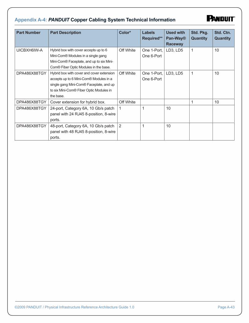
Appendix A-4: PANDUIT Copper Cabling System Technical Information
©2009 PANDUIT / Physical Infrastructure Reference Architecture Guide 1.0 Page A-43
Part Number Part Description Color* Labels Required**
Used with Pan-Way® Raceway
Std. Pkg. Quantity
Std. Ctn. Quantity
UICBXH6IW-A Hybrid box with cover accepts up to 6
Mini-Com® Modules in a single gang
Mini-Com® Faceplate, and up to six Mini-
Com® Fiber Optic Modules in the base.
Off White One 1-Port, One 6-Port
LD3, LD5 1 10
DPA486X88TGY Hybrid box with cover and cover extension
accepts up to 6 Mini-Com® Modules in a
single gang Mini-Com® Faceplate, and up
to six Mini-Com® Fiber Optic Modules in
the base.
Off White One 1-Port, One 6-Port
LD3, LD5 1 10
DPA486X88TGY Cover extension for hybrid box. Off White 1 10
DPA486X88TGY 24-port, Category 6A, 10 Gb/s patch panel with 24 RJ45 8-position, 8-wire ports.
1 1 10
DPA486X88TGY 48-port, Category 6A, 10 Gb/s patch panel with 48 RJ45 8-position, 8-wire ports.
2 1 10
B: Fiber Optic Cabling System Technical Information
Appendix A-1
©2009 PANDUIT / Physical Infrastructure Reference Architecture Guide 1.0 Page B-1
Appendix BPANDUIT Fiber Opticr Cabling System Technical Information
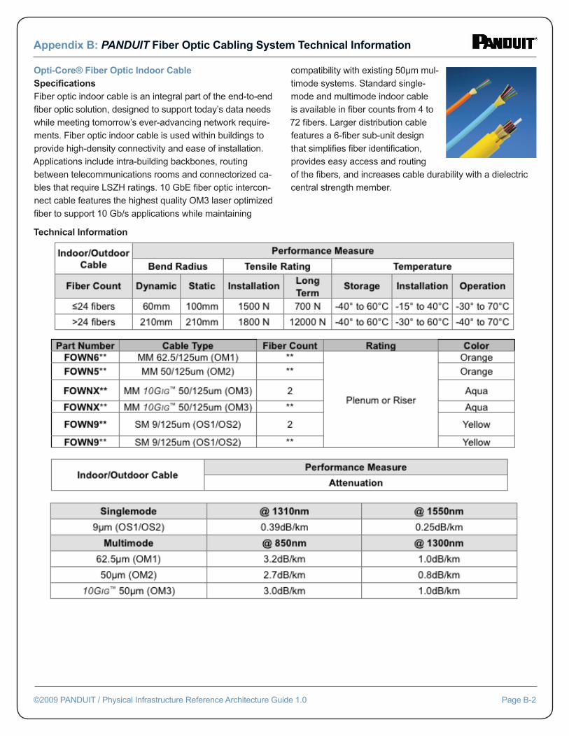
Opti-Core® Fiber Optic Indoor CableSpecifi cationsFiber optic indoor cable is an integral part of the end-to-end fi ber optic solution, designed to support today’s data needs while meeting tomorrow’s ever-advancing network require-ments. Fiber optic indoor cable is used within buildings to provide high-density connectivity and ease of installation. Applications include intra-building backbones, routing between telecommunications rooms and connectorized ca-bles that require LSZH ratings. 10 GbE fi ber optic intercon-nect cable features the highest quality OM3 laser optimizedfi ber to support 10 Gb/s applications while maintaining
compatibility with existing 50μm mul-timode systems. Standard single-mode and multimode indoor cable is available in fi ber counts from 4 to 72 fi bers. Larger distribution cable features a 6-fi ber sub-unit design that simplifi es fi ber identifi cation, provides easy access and routing of the fi bers, and increases cable durability with a dielectric central strength member.
Appendix B: PANDUIT Fiber Optic Cabling System Technical Information
©2009 PANDUIT / Physical Infrastructure Reference Architecture Guide 1.0 Page B-2
Technical Information
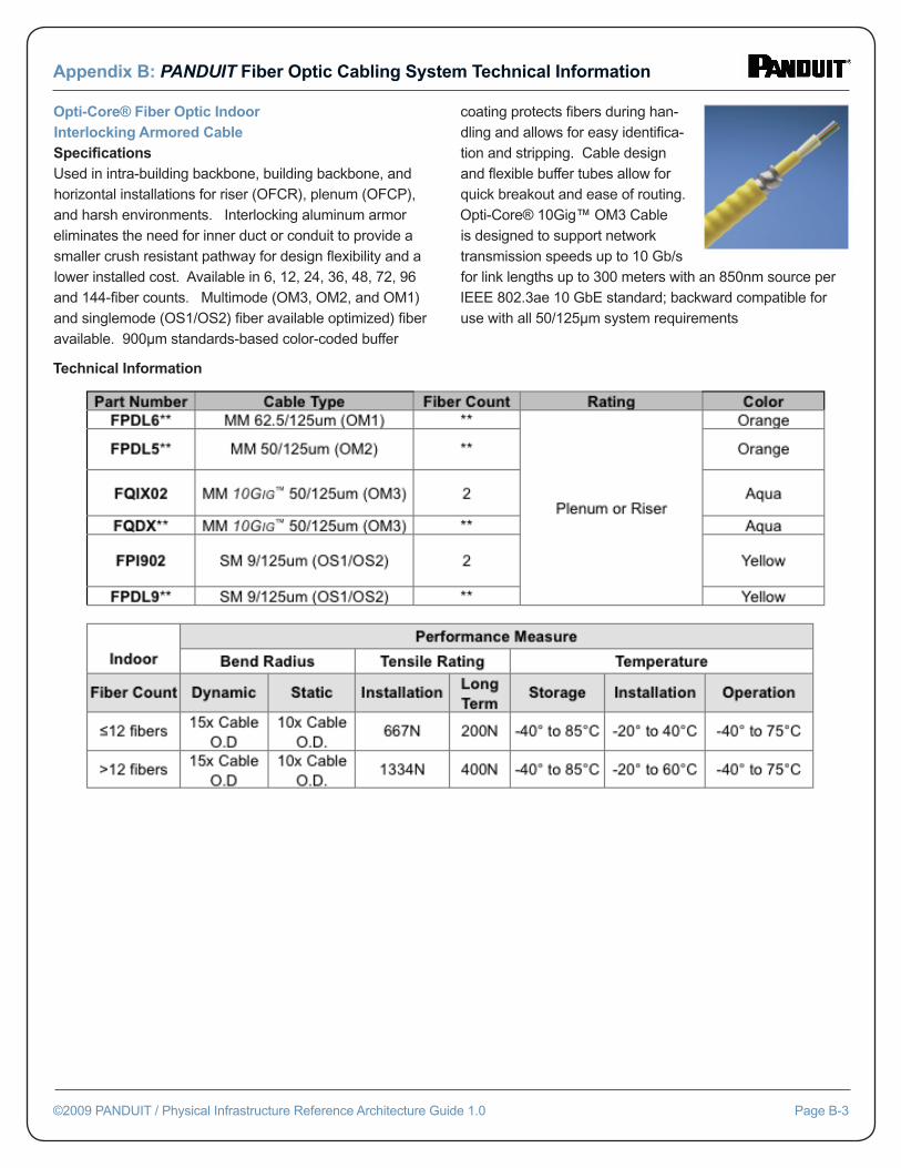
Opti-Core® Fiber Optic IndoorInterlocking Armored CableSpecifi cationsUsed in intra-building backbone, building backbone, and horizontal installations for riser (OFCR), plenum (OFCP), and harsh environments. Interlocking aluminum armor eliminates the need for inner duct or conduit to provide a smaller crush resistant pathway for design fl exibility and a lower installed cost. Available in 6, 12, 24, 36, 48, 72, 96 and 144-fi ber counts. Multimode (OM3, OM2, and OM1) and singlemode (OS1/OS2) fi ber available optimized) fi ber available. 900μm standards-based color-coded buffer
coating protects fi bers during han-dling and allows for easy identifi ca-tion and stripping. Cable design and fl exible buffer tubes allow for quick breakout and ease of routing. Opti-Core® 10Gig™ OM3 Cable is designed to support network transmission speeds up to 10 Gb/s for link lengths up to 300 meters with an 850nm source per IEEE 802.3ae 10 GbE standard; backward compatible for use with all 50/125μm system requirements
Appendix B: PANDUIT Fiber Optic Cabling System Technical Information
©2009 PANDUIT / Physical Infrastructure Reference Architecture Guide 1.0 Page B-3
Technical Information
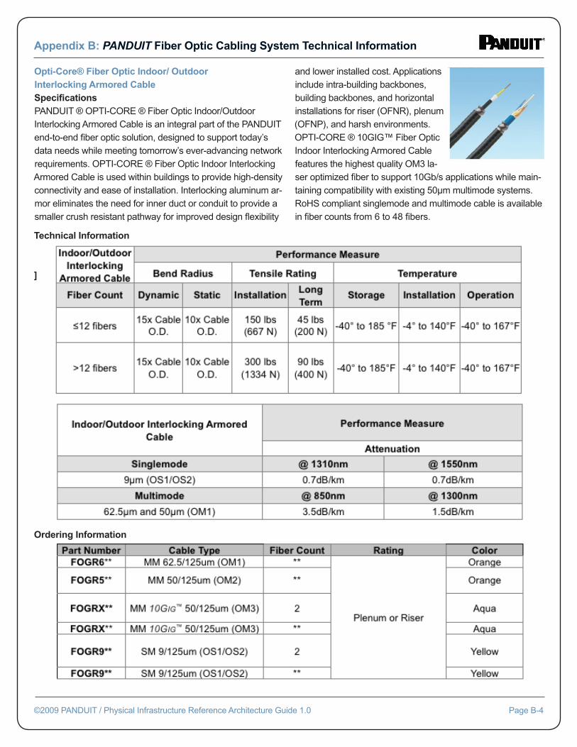
Opti-Core® Fiber Optic Indoor/ OutdoorInterlocking Armored CableSpecifi cationsPANDUIT ® OPTI-CORE ® Fiber Optic Indoor/Outdoor Interlocking Armored Cable is an integral part of the PANDUIT end-to-end fi ber optic solution, designed to support today’s data needs while meeting tomorrow’s ever-advancing network requirements. OPTI-CORE ® Fiber Optic Indoor Interlocking Armored Cable is used within buildings to provide high-density connectivity and ease of installation. Interlocking aluminum ar-mor eliminates the need for inner duct or conduit to provide a smaller crush resistant pathway for improved design fl exibility
and lower installed cost. Applications include intra-building backbones, building backbones, and horizontal installations for riser (OFNR), plenum (OFNP), and harsh environments. OPTI-CORE ® 10GIG™ Fiber Optic Indoor Interlocking Armored Cable features the highest quality OM3 la-ser optimized fi ber to support 10Gb/s applications while main-taining compatibility with existing 50μm multimode systems. RoHS compliant singlemode and multimode cable is available in fi ber counts from 6 to 48 fi bers.
Appendix B: PANDUIT Fiber Optic Cabling System Technical Information
©2009 PANDUIT / Physical Infrastructure Reference Architecture Guide 1.0 Page B-4
Technical Information
]
Ordering Information
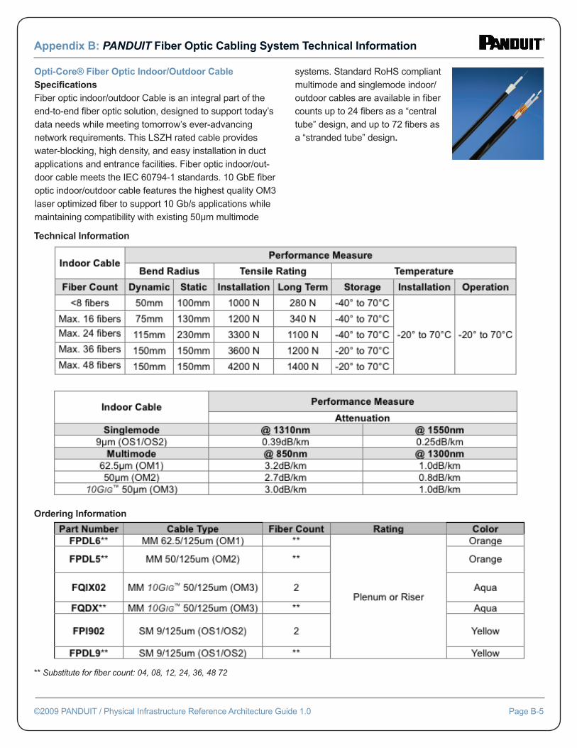
Opti-Core® Fiber Optic Indoor/Outdoor CableSpecifi cationsFiber optic indoor/outdoor Cable is an integral part of the end-to-end fi ber optic solution, designed to support today’s data needs while meeting tomorrow’s ever-advancing network requirements. This LSZH rated cable provides water-blocking, high density, and easy installation in duct applications and entrance facilities. Fiber optic indoor/out-door cable meets the IEC 60794-1 standards. 10 GbE fi ber optic indoor/outdoor cable features the highest quality OM3 laser optimized fi ber to support 10 Gb/s applications while maintaining compatibility with existing 50μm multimode
systems. Standard RoHS compliant multimode and singlemode indoor/outdoor cables are available in fi ber counts up to 24 fi bers as a “central tube” design, and up to 72 fi bers as a “stranded tube” design.
Appendix B: PANDUIT Fiber Optic Cabling System Technical Information
©2009 PANDUIT / Physical Infrastructure Reference Architecture Guide 1.0 Page B-5
Technical Information
Ordering Information
** Substitute for fi ber count: 04, 08, 12, 24, 36, 48 72
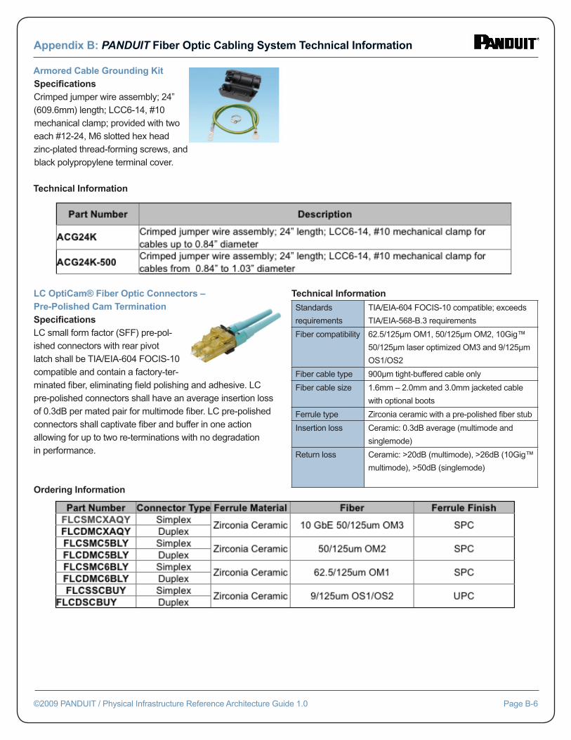
Armored Cable Grounding KitSpecifi cationsCrimped jumper wire assembly; 24” (609.6mm) length; LCC6-14, #10 mechanical clamp; provided with two each #12-24, M6 slotted hex head zinc-plated thread-forming screws, and black polypropylene terminal cover.
Technical Information
Appendix B: PANDUIT Fiber Optic Cabling System Technical Information
©2009 PANDUIT / Physical Infrastructure Reference Architecture Guide 1.0 Page B-6
LC OptiCam® Fiber Optic Connectors – Pre-Polished Cam TerminationSpecifi cationsLC small form factor (SFF) pre-pol-ished connectors with rear pivot latch shall be TIA/EIA-604 FOCIS-10 compatible and contain a factory-ter-minated fi ber, eliminating fi eld polishing and adhesive. LC pre-polished connectors shall have an average insertion loss of 0.3dB per mated pair for multimode fi ber. LC pre-polished connectors shall captivate fi ber and buffer in one action allowing for up to two re-terminations with no degradation in performance.
Ordering Information
Technical Information
Standards
requirements
TIA/EIA-604 FOCIS-10 compatible; exceeds
TIA/EIA-568-B.3 requirements
Fiber compatibility 62.5/125μm OM1, 50/125μm OM2, 10Gig™
50/125μm laser optimized OM3 and 9/125μm
OS1/OS2
Fiber cable type 900μm tight-buffered cable only
Fiber cable size 1.6mm – 2.0mm and 3.0mm jacketed cable
with optional boots
Ferrule type Zirconia ceramic with a pre-polished fi ber stub
Insertion loss Ceramic: 0.3dB average (multimode and
singlemode)
Return loss Ceramic: >20dB (multimode), >26dB (10Gig™
multimode), >50dB (singlemode)
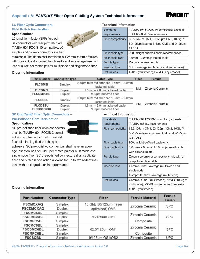
Appendix B: PANDUIT Fiber Optic Cabling System Technical Information
©2009 PANDUIT / Physical Infrastructure Reference Architecture Guide 1.0 Page B-7
LC Fiber Optic Connectors – Field Polish TerminationSpecifi cationsLC small form factor (SFF) fi eld pol-ish connectors with rear pivot latch are TIA/EIA-604 FOCIS-10 compatible. LC simplex and duplex connectors are fi eld terminable. The fi bers shall terminate in 1.25mm ceramic ferrules with non-optical disconnect functionality and an average insertion loss of 0.1dB per mated pair for multimode and singlemode fi ber.
Ordering Information
Technical Information
Standards
requirements
TIA/EIA-604 FOCIS-10 compatible; exceeds
TIA/EIA-568-B.3 requirements
Fiber compatibility 62.5/125μm OM1, 50/125μm OM2, 10Gig™
50/125μm laser optimized OM3 and 9/125μm
OS1/OS2
Fiber cable type 900μm tight-buffered cable recommended
Fiber cable size 1.6mm – 2.0mm jacketed cable
Ferrule type Zirconia ceramic ferrule
Insertion loss 0.1dB average (multimode and singlemode)
Return loss >20dB (multimode), >40dB (singlemode)
SC OptiCam® Fiber Optic Connectors – Pre-Polished Cam TerminationSpecifi cationsSC pre-polished fi ber optic connectors shall be TIA/EIA-604 FOCIS-3 compli-ant and contain a factory-terminated fi ber, eliminating fi eld polishing and adhesive. SC pre-polished connectors shall have an aver-age insertion loss of 0.3dB per mated pair for multimode and singlemode fi ber. SC pre-polished connectors shall captivate fi ber and buffer in one action allowing for up to two re-termina-tions with no degradation in performance.
Ordering Information
Technical Information
Standards
requirements
TIA/EIA-604 FOCIS-3 compliant; exceeds
TIA/EIA-568-B.3 requirements
Fiber compatibility 62.5/125μm OM1, 50/125μm OM2, 10Gig™
50/125μm laser optimized OM3 and 9/125μm
OS1/OS2
Fiber cable type 900μm tight-buffered cable only
Fiber cable size 1.6mm – 2.0mm and 3.0mm jacketed cable
with optional boots
Ferrule type Zirconia ceramic or composite ferrule with a
pre-polished fi ber stub
Insertion loss Ceramic: 0.3dB average (multimode and
singlemode)
Composite: 0.3dB average (multimode)
Return loss Ceramic: >20dB (multimode), >26dB (10Gig™
multimode), >50dB (singlemode) Composite:
>20dB (multimode)
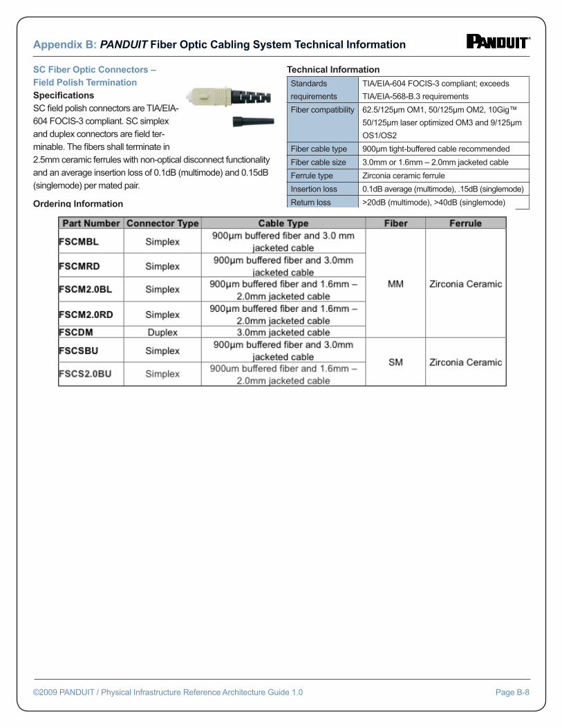
Appendix B: PANDUIT Fiber Optic Cabling System Technical Information
©2009 PANDUIT / Physical Infrastructure Reference Architecture Guide 1.0 Page B-8
SC Fiber Optic Connectors – Field Polish TerminationSpecifi cationsSC fi eld polish connectors are TIA/EIA-604 FOCIS-3 compliant. SC simplex and duplex connectors are fi eld ter-minable. The fi bers shall terminate in 2.5mm ceramic ferrules with non-optical disconnect functionality and an average insertion loss of 0.1dB (multimode) and 0.15dB (singlemode) per mated pair.
Ordering Information
Technical Information
Standards
requirements
TIA/EIA-604 FOCIS-3 compliant; exceeds
TIA/EIA-568-B.3 requirements
Fiber compatibility 62.5/125μm OM1, 50/125μm OM2, 10Gig™
50/125μm laser optimized OM3 and 9/125μm
OS1/OS2
Fiber cable type 900μm tight-buffered cable recommended
Fiber cable size 3.0mm or 1.6mm – 2.0mm jacketed cable
Ferrule type Zirconia ceramic ferrule
Insertion loss 0.1dB average (multimode), .15dB (singlemode)
Return loss >20dB (multimode), >40dB (singlemode)
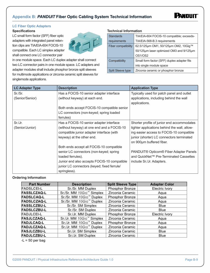
Appendix B: PANDUIT Fiber Optic Cabling System Technical Information
©2009 PANDUIT / Physical Infrastructure Reference Architecture Guide 1.0 Page B-9
LC Fiber Optic AdaptersSpecifi cationsLC small form factor (SFF) fi ber optic adapters with integrated panel reten-tion clips are TIA/EIA-604 FOCIS-10 compatible. Each LC simplex adapter shall connect one LC connector pair in one module space. Each LC duplex adapter shall connect two LC connector pairs in one module space. LC adapters and adapter modules shall include phosphor bronze split sleeves for multimode applications or zirconia ceramic split sleeves for singlemode applications.
Technical Information
Standards
requirements
TIA/EIA-604 FOCIS-10 compatible; exceeds-
TIA/EIA-568-B.3 requirements
Fiber compatibility 62.5/125μm OM1, 50/125μm OM2, 10Gig™
50/125μm laser optimized OM3 and 9/125μm
OS1/OS2
Compatibility Small form factor (SFF) duplex adapter fi ts
into single module space
Split Sleeve type Zirconia ceramic or phosphor bronze
LC Adapter Type Description Application Type
Sr./Sr.(Senior/Senior)
Has a FOCIS-10 senior adapter interface (without keyway) at each end.
Both ends accept FOCIS-10 compatible senior LC connectors (non-keyed; spring loaded ferrules)
Typically used for patch panel and outlet applications, including behind the wall applications.
Sr./Jr.(Senior/Junior)
Has a FOCIS-10 senior adapter interface (without keyway) at one end and a FOCIS-10 compatible junior adapter interface (with keyway) at the other end.
Both ends accept all FOCIS-10 compatible senior LC connectors (non-keyed; spring loaded ferrules).Junior end also accepts FOCIS-10 compatible junior LC connectors (keyed; fi xed ferrule/springless).
Shorter profi le of junior end accommodates tighter applications behind the wall, allow-ing easier access to FOCIS-10 compatible junior (shorter) LC connectors terminated on 900μm buffered fi ber.
PANDUIT® Opticom® Fiber Adapter Panels and QuickNet™ Pre-Terminated Cassettes include Sr./Jr. Adapters.
Ordering Information
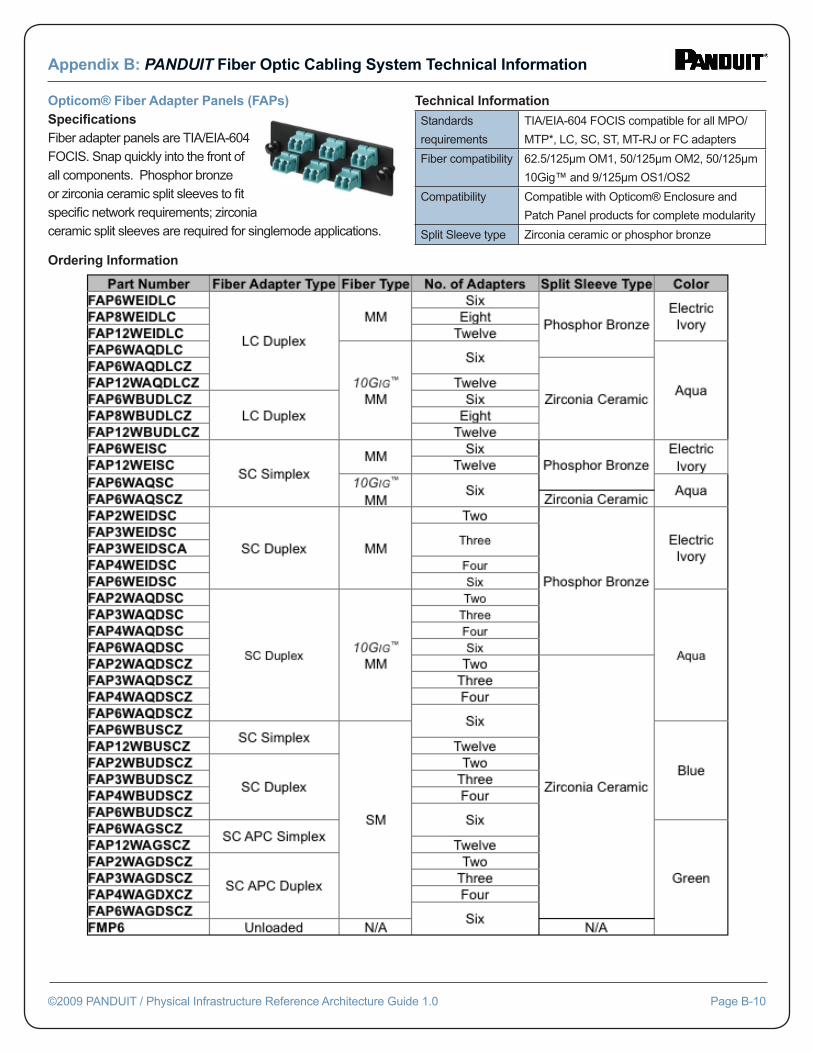
Appendix B: PANDUIT Fiber Optic Cabling System Technical Information
©2009 PANDUIT / Physical Infrastructure Reference Architecture Guide 1.0 Page B-10
Opticom® Fiber Adapter Panels (FAPs)Specifi cationsFiber adapter panels are TIA/EIA-604 FOCIS. Snap quickly into the front of all components. Phosphor bronze or zirconia ceramic split sleeves to fi t specifi c network requirements; zirconia ceramic split sleeves are required for singlemode applications.
Technical Information
Standards
requirements
TIA/EIA-604 FOCIS compatible for all MPO/
MTP*, LC, SC, ST, MT-RJ or FC adapters
Fiber compatibility 62.5/125μm OM1, 50/125μm OM2, 50/125μm
10Gig™ and 9/125μm OS1/OS2
Compatibility Compatible with Opticom® Enclosure and
Patch Panel products for complete modularity
Split Sleeve type Zirconia ceramic or phosphor bronze
Ordering Information
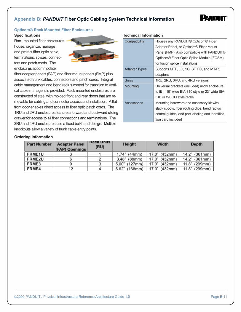
Appendix B: PANDUIT Fiber Optic Cabling System Technical Information
©2009 PANDUIT / Physical Infrastructure Reference Architecture Guide 1.0 Page B-11
Opticom® Rack Mounted Fiber EnclosuresSpecifi cationsRack mounted fi ber enclosures house, organize, manage and protect fi ber optic cable, terminations, splices, connec-tors and patch cords. The enclosures accommodate fi ber adapter panels (FAP) and fi ber mount panels (FMP) plus associated trunk cables, connectors and patch cords. Integral cable management and bend radius control for transition to verti-cal cable managers is provided. Rack mounted enclosures are constructed of steel with molded front and rear doors that are re-movable for cabling and connector access and installation. A fl at front door enables direct access to fi ber optic patch cords. The 1RU and 2RU enclosures feature a forward and backward sliding drawer for access to all fi ber connections and terminations. The 3RU and 4RU enclosures use a fi xed bulkhead design. Multiple knockouts allow a variety of trunk cable entry points.
Technical Information
Compatibility Houses any PANDUIT® Opticom® Fiber
Adapter Panel, or Opticom® Fiber Mount
Panel (FMP). Also compatible with PANDUIT®
Opticom® Fiber Optic Splice Module (FOSM)
for fusion splice installations
Adapter Types Supports MTP, LC, SC, ST, FC, and MT-RJ
adapters
Sizes 1RU, 2RU, 3RU, and 4RU versions
Mounting Universal brackets (included) allow enclosure
to fi t in 19” wide EIA-310 style or 23” wide EIA-
310 or WECO style racks
Accessories Mounting hardware and accessory kit with
slack spools, fi ber routing clips, bend radius
control guides, and port labeling and identifi ca-
tion card included
Ordering Information
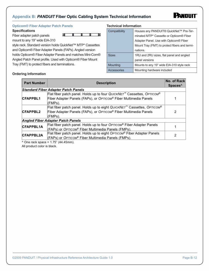
Appendix B: PANDUIT Fiber Optic Cabling System Technical Information
©2009 PANDUIT / Physical Infrastructure Reference Architecture Guide 1.0 Page B-12
Opticom® Fiber Adapter Patch PanelsSpecifi cationsFiber adapter patch panels mount to any 19” wide EIA-310 style rack. Standard version holds QuickNet™ MTP* Cassettes and Opticom® Fiber Adapter Panels (FAPs). Angled version holds Opticom® Fiber Adapter Panels and matches Mini-Com® Angled Patch Panel profi le. Used with Opticom® Fiber Mount Tray (FMT) to protect fi bers and terminations.
Technical Information
Compatibility Houses any PANDUIT® QuickNet™ Pre-Ter-
minated MTP* Cassette or Opticom® Fiber
Adapter Panel. Use with Opticom® Fiber
Mount Tray (FMT) to protect fi bers and termi-
nations.
Sizes 1RU and 2RU sizes, fl at panel and angled
panel versions
Mounting Mounts to any 19” wide EIA-310 style rack
Accessories Mounting hardware included
Ordering Information
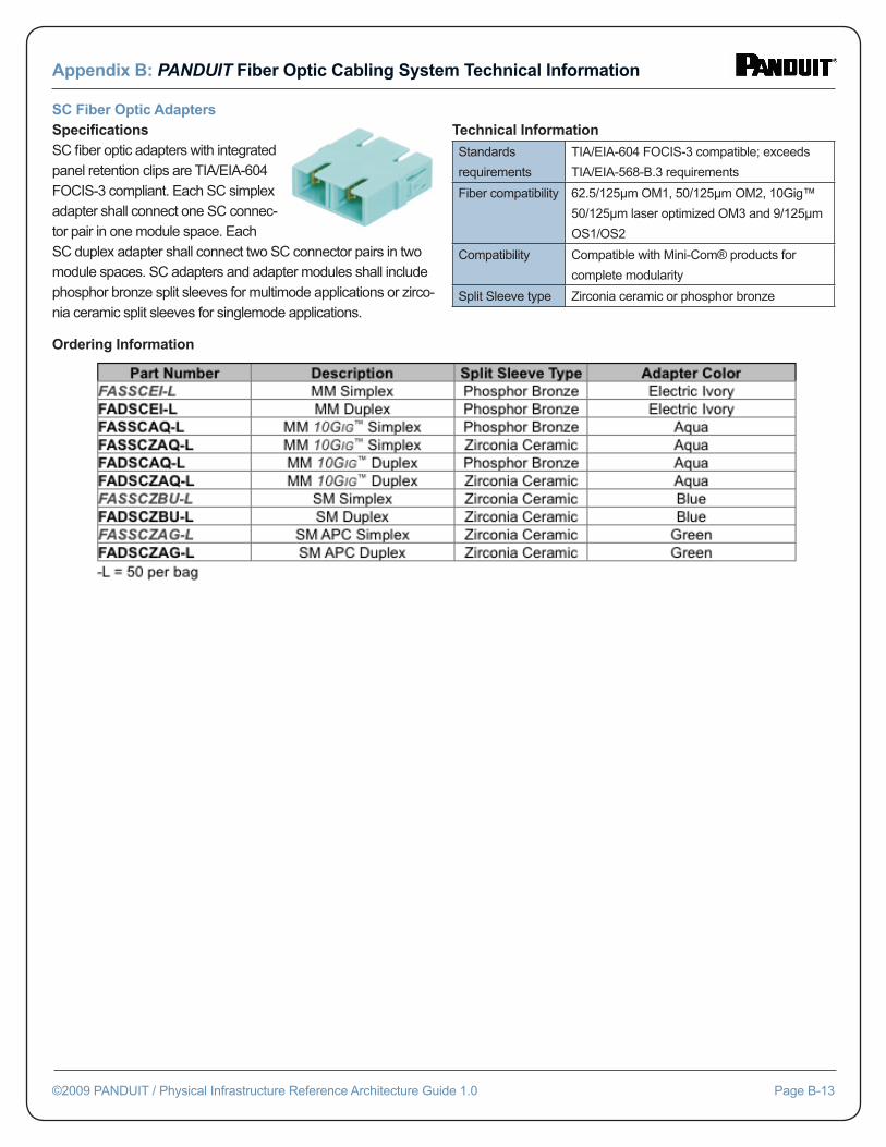
Appendix B: PANDUIT Fiber Optic Cabling System Technical Information
©2009 PANDUIT / Physical Infrastructure Reference Architecture Guide 1.0 Page B-13
SC Fiber Optic AdaptersSpecifi cationsSC fi ber optic adapters with integrated panel retention clips are TIA/EIA-604 FOCIS-3 compliant. Each SC simplex adapter shall connect one SC connec-tor pair in one module space. Each SC duplex adapter shall connect two SC connector pairs in two module spaces. SC adapters and adapter modules shall include phosphor bronze split sleeves for multimode applications or zirco-nia ceramic split sleeves for singlemode applications.
Technical Information
Standards
requirements
TIA/EIA-604 FOCIS-3 compatible; exceeds
TIA/EIA-568-B.3 requirements
Fiber compatibility 62.5/125μm OM1, 50/125μm OM2, 10Gig™
50/125μm laser optimized OM3 and 9/125μm
OS1/OS2
Compatibility Compatible with Mini-Com® products for
complete modularity
Split Sleeve type Zirconia ceramic or phosphor bronze
Ordering Information
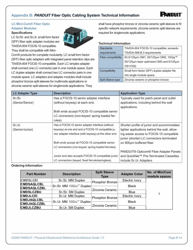
Appendix B: PANDUIT Fiber Optic Cabling System Technical Information
©2009 PANDUIT / Physical Infrastructure Reference Architecture Guide 1.0 Page B-14
LC Mini-Com® Fiber Optic Adapter ModulesSpecifi cationsLC Sr./Sr. and Sr./Jr. small form factor (SFF) fi ber optic adapter modules are TIA/EIA-604 FOCIS-10 compatible. They shall be compatible with Mini-Com® products for complete modularity. LC small form factor (SFF) fi ber optic adapters with integrated panel retention clips are TIA/EIA-604 FOCIS-10 compatible. Each LC simplex adapter shall connect one LC connector pair in one module space. Each LC duplex adapter shall connect two LC connector pairs in one module space. LC adapters and adapter modules shall include phosphor bronze split sleeves for multimode applications or zirconia ceramic split sleeves for singlemode applications. They
shall have phosphor bronze or zirconia ceramic split sleeves to fi t specifi c network requirements; zirconia ceramic split sleeves are required for singlemode applications.
Technical Information
Standards
requirements
TIA/EIA-604 FOCIS-10 compatible; exceeds-
TIA/EIA-568-B.3 requirements
Fiber compatibility 62.5/125μm OM1, 50/125μm OM2, 10Gig™
50/125μm laser optimized OM3 and 9/125μm
OS1/OS2
Compatibility Small form factor (SFF) duplex adapter fi ts
into single module space.
Split Sleeve type Zirconia ceramic or phosphor bronze
LC Adapter Type Description Application Type
Sr./Sr.(Senior/Senior)
Has a FOCIS-10 senior adapter interface (without keyway) at each end.
Both ends accept FOCIS-10 compatible senior LC connectors (non-keyed; spring loaded fer-rules).
Typically used for patch panel and outlet applications, including behind the wall applications.
Sr./Jr.(Senior/Junior)
Has a FOCIS-10 senior adapter interface (without
keyway) at one end and a FOCIS-10 compatible ju-
nior adapter interface (with keyway) at the other end.
Both ends accept all FOCIS-10 compatible senior
LC connectors (non-keyed; spring loaded ferrules).
Junior end also accepts FOCIS-10 compatible junior
LC connectors (keyed; fi xed ferrule/springless).
Shorter profi le of junior end accommodates tighter applications behind the wall, allow-ing easier access to FOCIS-10 compatible junior (shorter) LC connectors terminated on 900μm buffered fi ber.
PANDUIT® Opticom® Fiber Adapter Panels and QuickNet™ Pre-Terminated Cassettes include Sr./Jr. Adapters.
Ordering Information
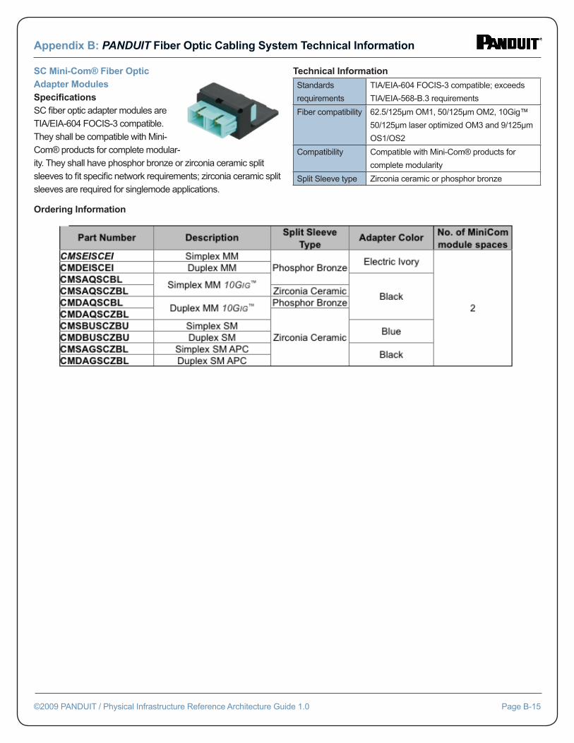
Appendix B: PANDUIT Fiber Optic Cabling System Technical Information
©2009 PANDUIT / Physical Infrastructure Reference Architecture Guide 1.0 Page B-15
SC Mini-Com® Fiber Optic Adapter ModulesSpecifi cationsSC fi ber optic adapter modules are TIA/EIA-604 FOCIS-3 compatible. They shall be compatible with Mini-Com® products for complete modular-ity. They shall have phosphor bronze or zirconia ceramic split sleeves to fi t specifi c network requirements; zirconia ceramic split sleeves are required for singlemode applications.
Technical Information
Standards
requirements
TIA/EIA-604 FOCIS-3 compatible; exceeds
TIA/EIA-568-B.3 requirements
Fiber compatibility 62.5/125μm OM1, 50/125μm OM2, 10Gig™
50/125μm laser optimized OM3 and 9/125μm
OS1/OS2
Compatibility Compatible with Mini-Com® products for
complete modularity
Split Sleeve type Zirconia ceramic or phosphor bronze
Ordering Information
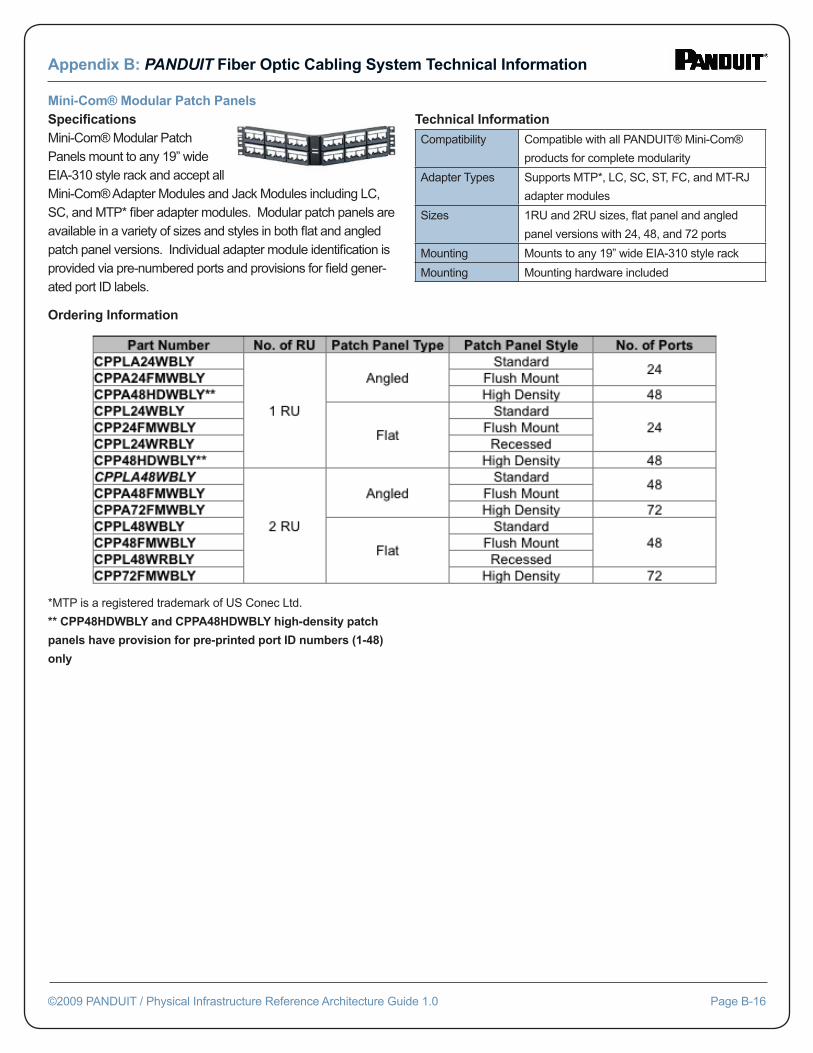
Appendix B: PANDUIT Fiber Optic Cabling System Technical Information
©2009 PANDUIT / Physical Infrastructure Reference Architecture Guide 1.0 Page B-16
Mini-Com® Modular Patch PanelsSpecifi cationsMini-Com® Modular Patch Panels mount to any 19” wide EIA-310 style rack and accept all Mini-Com® Adapter Modules and Jack Modules including LC, SC, and MTP* fi ber adapter modules. Modular patch panels are available in a variety of sizes and styles in both fl at and angled patch panel versions. Individual adapter module identifi cation is provided via pre-numbered ports and provisions for fi eld gener-ated port ID labels.
Technical Information
Compatibility Compatible with all PANDUIT® Mini-Com®
products for complete modularity
Adapter Types Supports MTP*, LC, SC, ST, FC, and MT-RJ
adapter modules
Sizes 1RU and 2RU sizes, fl at panel and angled
panel versions with 24, 48, and 72 ports
Mounting Mounts to any 19” wide EIA-310 style rack
Mounting Mounting hardware included
Ordering Information
*MTP is a registered trademark of US Conec Ltd.
** CPP48HDWBLY and CPPA48HDWBLY high-density patch
panels have provision for pre-printed port ID numbers (1-48)
only
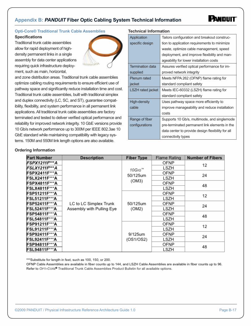
Appendix B: PANDUIT Fiber Optic Cabling System Technical Information
©2009 PANDUIT / Physical Infrastructure Reference Architecture Guide 1.0 Page B-17
Opti-Core® Traditional Trunk Cable AssembliesSpecifi cationsTraditional trunk cable assemblies allow for rapid deployment of high-density permanent links in a single assembly for data center applications requiring quick infrastructure deploy-ment, such as main, horizontal, and zone distribution areas. Traditional trunk cable assemblies optimize cabling routing requirements to ensure effi cient use of pathway space and signifi cantly reduce installation time and cost. Traditional trunk cable assemblies, built with traditional simplex and duplex connectivity (LC, SC, and ST), guarantee compat-ibility, fl exibility, and system performance in all permanent link applications. All traditional trunk cable assemblies are factory terminated and tested to deliver verifi ed optical performance and reliability for improved network integrity. 10 GbE versions provide 10 Gb/s network performance up to 300M per IEEE 802.3ae 10 GbE standard while maintaining compatibility with legacy sys-tems. 150M and 550M link length options are also available.
Technical Information
Application
specifi c design
Tailors confi guration and breakout construc-
tion to application requirements to minimize
waste, optimize cable management, speed
deployment, and improve fl exibility and man-
ageability for lower installation costs
Termination data
supplied
Assures verifi ed optical performance for im-
proved network integrity
Plenum rated
jacket
Meets NFPA 262 (OFNP) fl ame rating for
standard compliant safety
LSZH rated jacket Meets IEC-60332 (LSZH) fl ame rating for
standard compliant safety
High-density
cable
Uses pathway space more effi ciently to
improve manageability and reduce installation
costs
Range of fi ber
confi gurations
Supports 10 Gb/s, multimode, and singlemode
pre-terminated permanent link elements in the
data center to provide design fl exibility for all
connectivity types
Ordering Information
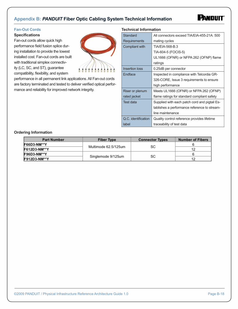
Appendix B: PANDUIT Fiber Optic Cabling System Technical Information
©2009 PANDUIT / Physical Infrastructure Reference Architecture Guide 1.0 Page B-18
Fan-Out CordsSpecifi cationsFan-out cords allow quick high performance fi eld fusion splice dur-ing installation to provide the lowest installed cost. Fan-out cords are built with traditional simplex connectiv-ity (LC, SC, and ST), guarantee compatibility, fl exibility, and system performance in all permanent link applications. All Fan-out cords are factory terminated and tested to deliver verifi ed optical perfor-mance and reliability for improved network integrity.
Technical Information
Standard
Requirements
All connectors exceed TIA/EIA-455-21A: 500
mating cycles
Compliant with TIA/EIA-568-B.3
TIA-604-5 (FOCIS-5)
UL1666 (OFNR) or NFPA 262 (OFNP) fl ame
ratings
Insertion loss 0.25dB per connector
Endface Inspected in compliance with Telcordia GR-
326-CORE, Issue 3 requirements to ensure
high performance
Riser or plenum
rated jacket
Meets UL1666 (OFNR) or NFPA 262 (OFNP)
fl ame ratings for standard compliant safety
Test data Supplied with each patch cord and pigtail Es-
tablishes a performance reference to stream-
line maintenance
Q.C. identifi cation
label
Quality control reference provides lifetime
traceability of test data
Ordering Information
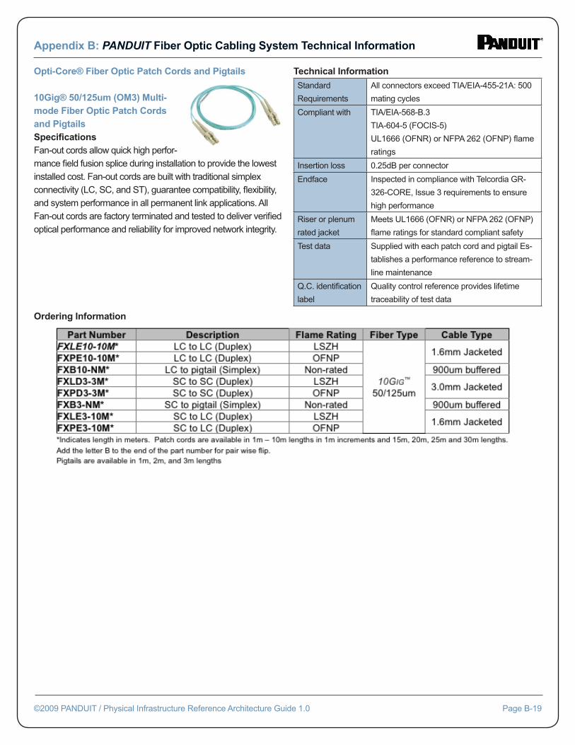
Appendix B: PANDUIT Fiber Optic Cabling System Technical Information
©2009 PANDUIT / Physical Infrastructure Reference Architecture Guide 1.0 Page B-19
Opti-Core® Fiber Optic Patch Cords and Pigtails
10Gig® 50/125um (OM3) Multi-mode Fiber Optic Patch Cords and PigtailsSpecifi cationsFan-out cords allow quick high perfor-mance fi eld fusion splice during installation to provide the lowest installed cost. Fan-out cords are built with traditional simplex connectivity (LC, SC, and ST), guarantee compatibility, fl exibility, and system performance in all permanent link applications. All Fan-out cords are factory terminated and tested to deliver verifi ed optical performance and reliability for improved network integrity.
Technical Information
Standard
Requirements
All connectors exceed TIA/EIA-455-21A: 500
mating cycles
Compliant with TIA/EIA-568-B.3
TIA-604-5 (FOCIS-5)
UL1666 (OFNR) or NFPA 262 (OFNP) fl ame
ratings
Insertion loss 0.25dB per connector
Endface Inspected in compliance with Telcordia GR-
326-CORE, Issue 3 requirements to ensure
high performance
Riser or plenum
rated jacket
Meets UL1666 (OFNR) or NFPA 262 (OFNP)
fl ame ratings for standard compliant safety
Test data Supplied with each patch cord and pigtail Es-
tablishes a performance reference to stream-
line maintenance
Q.C. identifi cation
label
Quality control reference provides lifetime
traceability of test data
Ordering Information
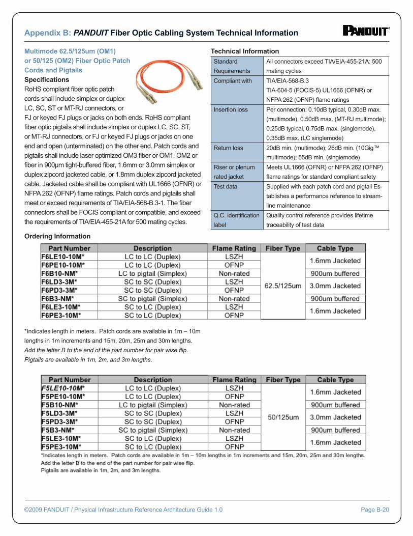
Appendix B: PANDUIT Fiber Optic Cabling System Technical Information
©2009 PANDUIT / Physical Infrastructure Reference Architecture Guide 1.0 Page B-20
Multimode 62.5/125um (OM1) or 50/125 (OM2) Fiber Optic Patch Cords and PigtailsSpecifi cationsRoHS compliant fi ber optic patch cords shall include simplex or duplex LC, SC, ST or MT-RJ connectors, or FJ or keyed FJ plugs or jacks on both ends. RoHS compliant fi ber optic pigtails shall include simplex or duplex LC, SC, ST, or MT-RJ connectors, or FJ or keyed FJ plugs or jacks on one end and open (unterminated) on the other end. Patch cords and pigtails shall include laser optimized OM3 fi ber or OM1, OM2 or fi ber in 900μm tight-buffered fi ber, 1.6mm or 3.0mm simplex or duplex zipcord jacketed cable, or 1.8mm duplex zipcord jacketed cable. Jacketed cable shall be compliant with UL1666 (OFNR) or NFPA 262 (OFNP) fl ame ratings. Patch cords and pigtails shall meet or exceed requirements of TIA/EIA-568-B.3-1. The fi ber connectors shall be FOCIS compliant or compatible, and exceed the requirements of TIA/EIA-455-21A for 500 mating cycles.
Technical Information
Standard
Requirements
All connectors exceed TIA/EIA-455-21A: 500
mating cycles
Compliant with TIA/EIA-568-B.3
TIA-604-5 (FOCIS-5) UL1666 (OFNR) or
NFPA 262 (OFNP) fl ame ratings
Insertion loss Per connection: 0.10dB typical, 0.30dB max.
(multimode), 0.50dB max. (MT-RJ multimode);
0.25dB typical, 0.75dB max. (singlemode),
0.35dB max. (LC singlemode)
Return loss 20dB min. (multimode); 26dB min. (10Gig™
multimode); 55dB min. (singlemode)
Riser or plenum
rated jacket
Meets UL1666 (OFNR) or NFPA 262 (OFNP)
fl ame ratings for standard compliant safety
Test data Supplied with each patch cord and pigtail Es-
tablishes a performance reference to stream-
line maintenance
Q.C. identifi cation
label
Quality control reference provides lifetime
traceability of test data
Ordering Information
*Indicates length in meters. Patch cords are available in 1m – 10m
lengths in 1m increments and 15m, 20m, 25m and 30m lengths.
Add the letter B to the end of the part number for pair wise fl ip.
Pigtails are available in 1m, 2m, and 3m lengths.
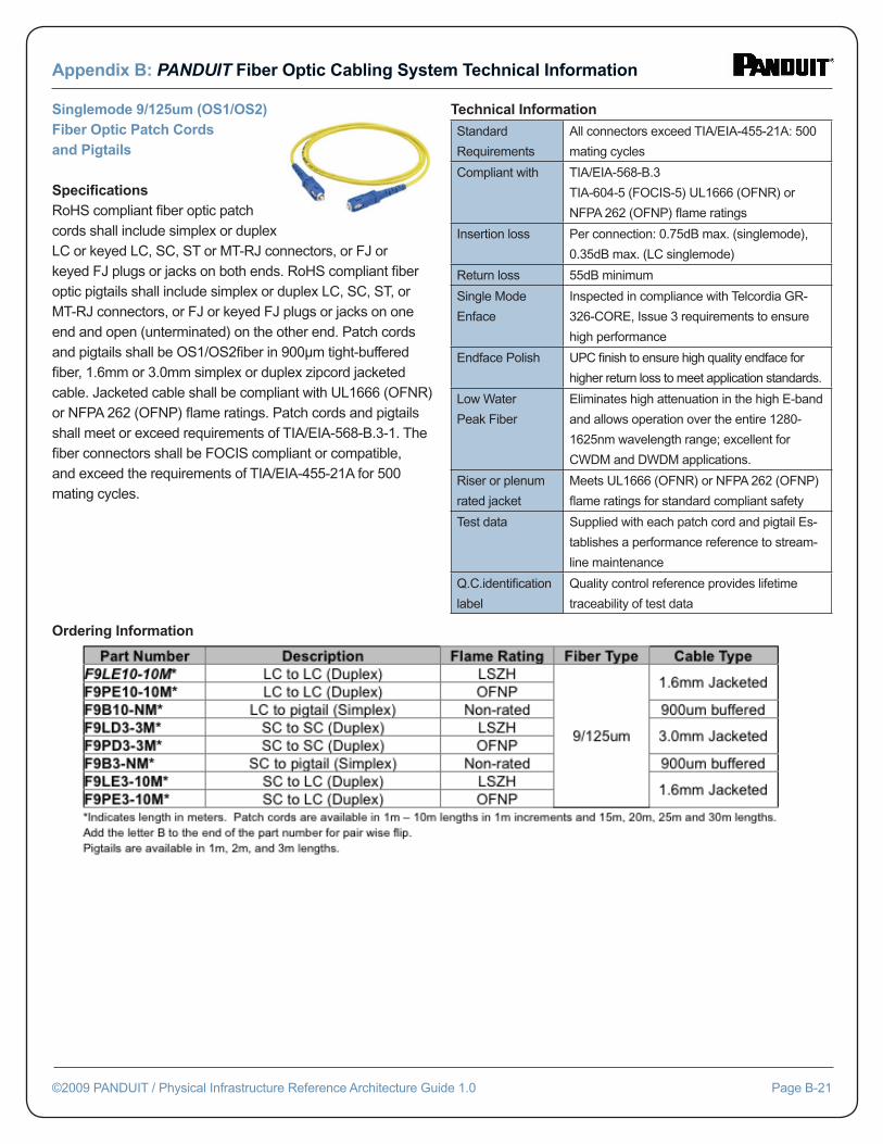
Appendix B: PANDUIT Fiber Optic Cabling System Technical Information
©2009 PANDUIT / Physical Infrastructure Reference Architecture Guide 1.0 Page B-21
Singlemode 9/125um (OS1/OS2) Fiber Optic Patch Cords and Pigtails
Specifi cationsRoHS compliant fi ber optic patch cords shall include simplex or duplex LC or keyed LC, SC, ST or MT-RJ connectors, or FJ or keyed FJ plugs or jacks on both ends. RoHS compliant fi ber optic pigtails shall include simplex or duplex LC, SC, ST, or MT-RJ connectors, or FJ or keyed FJ plugs or jacks on one end and open (unterminated) on the other end. Patch cords and pigtails shall be OS1/OS2fi ber in 900μm tight-buffered fi ber, 1.6mm or 3.0mm simplex or duplex zipcord jacketed cable. Jacketed cable shall be compliant with UL1666 (OFNR) or NFPA 262 (OFNP) fl ame ratings. Patch cords and pigtails shall meet or exceed requirements of TIA/EIA-568-B.3-1. The fi ber connectors shall be FOCIS compliant or compatible, and exceed the requirements of TIA/EIA-455-21A for 500 mating cycles.
Technical Information
Standard
Requirements
All connectors exceed TIA/EIA-455-21A: 500
mating cycles
Compliant with TIA/EIA-568-B.3
TIA-604-5 (FOCIS-5) UL1666 (OFNR) or
NFPA 262 (OFNP) fl ame ratings
Insertion loss Per connection: 0.75dB max. (singlemode),
0.35dB max. (LC singlemode)
Return loss 55dB minimum
Single Mode
Enface
Inspected in compliance with Telcordia GR-
326-CORE, Issue 3 requirements to ensure
high performance
Endface Polish UPC fi nish to ensure high quality endface for
higher return loss to meet application standards.
Low Water
Peak Fiber
Eliminates high attenuation in the high E-band
and allows operation over the entire 1280-
1625nm wavelength range; excellent for
CWDM and DWDM applications.
Riser or plenum
rated jacket
Meets UL1666 (OFNR) or NFPA 262 (OFNP)
fl ame ratings for standard compliant safety
Test data Supplied with each patch cord and pigtail Es-
tablishes a performance reference to stream-
line maintenance
Q.C.identifi cation
label
Quality control reference provides lifetime
traceability of test data
Ordering Information
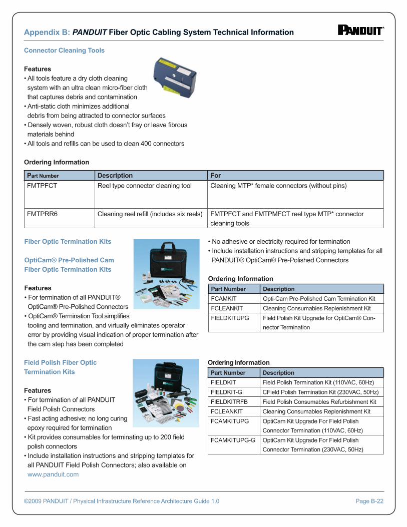
Appendix B: PANDUIT Fiber Optic Cabling System Technical Information
©2009 PANDUIT / Physical Infrastructure Reference Architecture Guide 1.0 Page B-22
Connector Cleaning Tools
Features• All tools feature a dry cloth cleaning system with an ultra clean micro-fi ber cloth that captures debris and contamination• Anti-static cloth minimizes additional debris from being attracted to connector surfaces• Densely woven, robust cloth doesn’t fray or leave fi brous materials behind• All tools and refi lls can be used to clean 400 connectors
Ordering Information
Part Number Description For
FMTPFCT Reel type connector cleaning tool Cleaning MTP* female connectors (without pins)
FMTPRR6 Cleaning reel refi ll (includes six reels) FMTPFCT and FMTPMFCT reel type MTP* connector cleaning tools
Fiber Optic Termination Kits
OptiCam® Pre-Polished Cam Fiber Optic Termination Kits
Features• For termination of all PANDUIT® OptiCam® Pre-Polished Connectors• OptiCam® Termination Tool simplifi es tooling and termination, and virtually eliminates operator error by providing visual indication of proper termination after the cam step has been completed
• No adhesive or electricity required for termination• Include installation instructions and stripping templates for all PANDUIT® OptiCam® Pre-Polished Connectors
Ordering Information
Part Number Description
FCAMKIT Opti-Cam Pre-Polished Cam Termination Kit
FCLEANKIT Cleaning Consumables Replenishment Kit
FIELDKITUPG Field Polish Kit Upgrade for OptiCam® Con-
nector Termination
Field Polish Fiber Optic Termination Kits
Features• For termination of all PANDUIT Field Polish Connectors• Fast acting adhesive; no long curing epoxy required for termination• Kit provides consumables for terminating up to 200 fi eld polish connectors• Include installation instructions and stripping templates for all PANDUIT Field Polish Connectors; also available on www.panduit.com
Ordering Information
Part Number Description
FIELDKIT Field Polish Termination Kit (110VAC, 60Hz)
FIELDKIT-G CField Polish Termination Kit (230VAC, 50Hz)
FIELDKITRFB Field Polish Consumables Refurbishment Kit
FCLEANKIT Cleaning Consumables Replenishment Kit
FCAMKITUPG OptiCam Kit Upgrade For Field Polish
Connector Termination (110VAC, 60Hz)
FCAMKITUPG-G OptiCam Kit Upgrade For Field Polish
Connector Termination (230VAC, 50Hz)
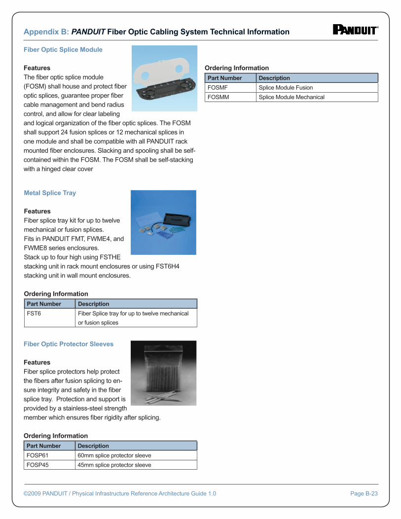
Appendix B: PANDUIT Fiber Optic Cabling System Technical Information
©2009 PANDUIT / Physical Infrastructure Reference Architecture Guide 1.0 Page B-23
Fiber Optic Splice Module
FeaturesThe fi ber optic splice module (FOSM) shall house and protect fi ber optic splices, guarantee proper fi ber cable management and bend radius control, and allow for clear labeling and logical organization of the fi ber optic splices. The FOSM shall support 24 fusion splices or 12 mechanical splices in one module and shall be compatible with all PANDUIT rack mounted fi ber enclosures. Slacking and spooling shall be self-contained within the FOSM. The FOSM shall be self-stacking with a hinged clear cover
Ordering Information
Part Number Description
FOSMF Splice Module Fusion
FOSMM Splice Module Mechanical
Metal Splice Tray
FeaturesFiber splice tray kit for up to twelve mechanical or fusion splices.Fits in PANDUIT FMT, FWME4, and FWME8 series enclosures. Stack up to four high using FSTHE stacking unit in rack mount enclosures or using FST6H4 stacking unit in wall mount enclosures.
Ordering Information
Part Number Description
FST6 Fiber Splice tray for up to twelve mechanical
or fusion splices
Fiber Optic Protector Sleeves
FeaturesFiber splice protectors help protect the fi bers after fusion splicing to en-sure integrity and safety in the fi ber splice tray. Protection and support is provided by a stainless-steel strength member which ensures fi ber rigidity after splicing.
Ordering Information
Part Number Description
FOSP61 60mm splice protector sleeve
FOSP45 45mm splice protector sleeve
C-1: Example Specifi cation Document for GES Connections
C-2: Example Specifi cation Document for Communications Systems
C-3: Example Visual Inspection and Documentation Process
©2009 PANDUIT / Physical Infrastructure Reference Architecture Guide 1.0 Page C-1
Appendix C:PANDUIT Grounding and Bonding System Technical Information
Appendix C-1: Example Grounding and Bonding SystemSpecifi cation Document for GES Connections
Direct Burial Compression Grounding System Specifi cation Sheet
Scope The scope of this specifi cation includes the materials, design, marking, installation, inspectability, and performance of grounding connectors used for direct burial in earth or concrete. All connectors shall meet the requirements of this specifi cation.
Materials Connector body shall be of wrought or cast copper
Design All connectors shall: • Utilize irreversible compression technology • Be factory-fi lled with an oxide-inhibiting compound • Utilize vacuum-sealed packaging to guarantee that the oxide-inhibiting compound is not rubbed off the part during shipping or before installation
Marking • Connector and matching installation die shall be color-coded to ensure proper die selection • Clearly marked with manufacturer, catalog number, conductor size, and required compression tool die index number • Marked with “DB” to indicate that the parts are for direct burial • Labeled with the specifi c types, sizes, and combina tions of conductors and other items connected approved by a nationally recognized testing laboratory (NRTL) • Listed and labeled as defi ned in NFPA 70 (National Electrical Code – NEC)
Installation • Connectors shall be installed as per manufactur- er’s instructions, including surface preparation, in stallation tools, crimping dies, and the required number of crimps • Connectors shall be installable in any weather, including wet or extreme cold (-40º F) conditions • Completing the connections shall require that no hazardous material be brought into the work site
Inspectability • When crimped, die index numbers shall be em bossed upon the part. The embossed die index numbers shall match the die index numbers printed on the part • Installation process shall indicate that the perfor- mance requirements of IEEE Std 837™-2002 are met. The markings shall be an integral part of the crimping process, and must indicate that all steps have been met. Example of acceptable indication includes that the die index numbers are embossed on the part once for UL/CSA only, and twice for IEEE Std 837™-2002
Performance Connections shall comply with the following standards: • IEEE Std 837™-2002 – Standard for Qualifying Per manent Connections Used in Substation Grounding • NFPA 70™ – National Electrical Code • UL 467 – Grounding and Bonding Equipment, for • CSA C22.1 – Canadian Electrical Code, Part I • MIL-STD-202G (METHOD 201A) – Department of Defense: Test Method Standard: Electronic and Electrical Component Parts (Vibration)
Appendix C: PANDUIT Grounding and Bonding System Technical Information
©2009 PANDUIT / Physical Infrastructure Reference Architecture Guide 1.0 Page C-2
Appendix C-2:Example Grounding and Bonding SystemSpecifi cation Document for Communications Systems
CSI SECTION 270526GROUNDING AND BONDING FOR COMMUNICATIONS SYSTEMS
The purpose of this document is to provide documentation to ca-
bling professionals interested in providing their customer a standard
specifi cation applicable to commercial building structured cabling
applications.
The documentation includes: Product specifi cations, minimum
product performance, structured cabling design considerations and
installation guidelines.
The information contained in this document is based on our ex-
perience to date and is believed to be reliable. It is intended as a
guide for use by persons having technical skill and is to be used
with their own discretion and risk. We do not guarantee favorable
results or assume any liability in connection with its use. Dimen-
sions contained herein are for reference purposes only. For specifi c
dimensional requirements consult the factory. This publication is not
to be taken as a license to operate under, or a recommendation to
infringe any existing patents. This supercedes and voids all previ-
ous literature, etc.
It is highly recommended and the issuer’s responsibility to have
any RFQ documents, including those based on this general format,
reviewed by the issuing company’s professional advisors before it
is released to the public. In no way may this document be used in
a manner that is detrimental to the interests of Panduit and/or its
subsidiaries.
Appendix C: PANDUIT Grounding and Bonding System Technical Information
©2009 PANDUIT / Physical Infrastructure Reference Architecture Guide 1.0 Page C-3
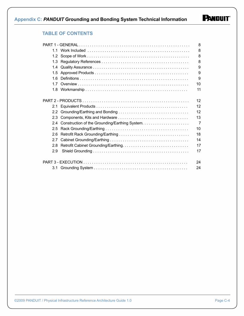
TABLE OF CONTENTS
PART 1 - GENERAL . . . . . . . . . . . . . . . . . . . . . . . . . . . . . . . . . . . . . . . . . . . . . . . . . . . . 8 1.1 Work Included . . . . . . . . . . . . . . . . . . . . . . . . . . . . . . . . . . . . . . . . . . . . . . . . 8 1.2 Scope of Work . . . . . . . . . . . . . . . . . . . . . . . . . . . . . . . . . . . . . . . . . . . . . . . . 8 1.3 Regulatory References . . . . . . . . . . . . . . . . . . . . . . . . . . . . . . . . . . . . . . . . . 8 1.4 Quality Assurance . . . . . . . . . . . . . . . . . . . . . . . . . . . . . . . . . . . . . . . . . . . . . 9 1.5 Approved Products . . . . . . . . . . . . . . . . . . . . . . . . . . . . . . . . . . . . . . . . . . . . 9 1.6 Defi nitions . . . . . . . . . . . . . . . . . . . . . . . . . . . . . . . . . . . . . . . . . . . . . . . . . . . 9 1.7 Overview . . . . . . . . . . . . . . . . . . . . . . . . . . . . . . . . . . . . . . . . . . . . . . . . . . . . 10 1.8 Workmanship . . . . . . . . . . . . . . . . . . . . . . . . . . . . . . . . . . . . . . . . . . . . . . . . 11
PART 2 - PRODUCTS . . . . . . . . . . . . . . . . . . . . . . . . . . . . . . . . . . . . . . . . . . . . . . . . . . 12 2.1 Equivalent Products . . . . . . . . . . . . . . . . . . . . . . . . . . . . . . . . . . . . . . . . . . . 12 2.2 Grounding/Earthing and Bonding . . . . . . . . . . . . . . . . . . . . . . . . . . . . . . . . . 12 2.3 Components, Kits and Hardware . . . . . . . . . . . . . . . . . . . . . . . . . . . . . . . . . 13 2.4 Construction of the Grounding/Earthing System. . . . . . . . . . . . . . . . . . . . . . 7 2.5 Rack Grounding/Earthing . . . . . . . . . . . . . . . . . . . . . . . . . . . . . . . . . . . . . . . 10 2.6 Retrofi t Rack Grounding/Earthing . . . . . . . . . . . . . . . . . . . . . . . . . . . . . . . . . 18 2.7 Cabinet Grounding/Earthing . . . . . . . . . . . . . . . . . . . . . . . . . . . . . . . . . . . . . 14 2.8 Retrofi t Cabinet Grounding/Earthing. . . . . . . . . . . . . . . . . . . . . . . . . . . . . . . 17 2.9 Shield Grounding . . . . . . . . . . . . . . . . . . . . . . . . . . . . . . . . . . . . . . . . . . . . . 17
PART 3 - EXECUTION . . . . . . . . . . . . . . . . . . . . . . . . . . . . . . . . . . . . . . . . . . . . . . . . . 24 3.1 Grounding System . . . . . . . . . . . . . . . . . . . . . . . . . . . . . . . . . . . . . . . . . . . . 24
Appendix C: PANDUIT Grounding and Bonding System Technical Information
©2009 PANDUIT / Physical Infrastructure Reference Architecture Guide 1.0 Page C-4
SECTION 271116
Part 1 - General
1.1 Work Included
A. Provide all labor, materials, tools and equipment required for the complete installation of work called for in the Construction Documents
1.2 Scope of Work
A. This document describes the products and execution requirements relating to furnishing and installing Grounding/Earthing and Bonding for Communications Systems.
B. This section includes minimum requirements for the following:
• Grounding/Earthing System • Telecommunications Grounding Busbar (TGB) • Telecommunications Main Grounding Busbar (TMGB) • Telecommunications Bonding Backbone (TBB) • Rack Grounding/Earthing and Bonding • Cabinet Grounding/Earthing and Bonding • Shield Grounding/Earthing and Bonding
C. All cables and related terminations, support and grounding/earthing hardware shall be furnished, in- stalled, wired, tested, labeled, and documented by the telecommunications contractor as detailed in this document.
D. Product specifi cations, general design considerations, and installation guidelines are provided in this document. Quantities grounding/earthing products, typical installa- tion details and cable routing will be provided as an attachment to this document. If the bid documents are in confl ict, this specifi cation shall take precedence. The successful vendor shall meet or exceed all require- ments for the cable system described in this document.
1.3 Regulatory References
A. The following industry standards are the basis for the grounding/earthing and bonding system described in this document.
1. NFPA • NFPA-70 National Electric Code (NEC) 2. IEEE • Std 1100 IEEE Recommend Practice for Powering and Grounding Electronic Equipment (IEEE Emerald Book) 3. TIA/EIA • TIA-942 Telecommunications Infrastructure Standard for Data Centers • J-STD-607-A Commercial Building Grounding/Bonding Requirements • TIA/EIA-606 Administration Standard for the Telecommunications Infrastructure of Commercial Buildings International Standard • BS EN 50310:2000 Application of equipotential bonding and earthing in Buildings with information technology equipment B. The most recent versions of all documents apply to this project. If there is a confl ict between applicable documents, the order above shall dictate the order of precedence in resolving the issue unless an enforce able local or national code is in effect.
1.4 Quality Assurance
A. See the Panduit Electrical Product Warranty on www. panduit.com/warranty
1.5 Approved Products
A. Approved grounding/earthing system manufacturer: PANDUIT
B. Approved telecommunications grounding busbar manufacturer: PANDUIT
C. Approved rack grounding kit manufacturer: PANDUIT
Appendix C: PANDUIT Grounding and Bonding System Technical Information
©2009 PANDUIT / Physical Infrastructure Reference Architecture Guide 1.0 Page C-5
D. Approved retrofi t rack grounding kit manufacturer: PANDUIT
E. Approved cabinet grounding kit manufacturer: PANDUIT
F. Approved retrofi t cabinet grounding kit manufac- turer: PANDUIT
G. Approved shielded cabling grounding kit manufac- turer: PANDUIT
1.6 Defi nitions
Bonding – The permanent joining of metallic parts to form an electrically conductive path that will assure electrical continuity and the capacity to conduct safely any current likely to be imposed.
Mesh Common Bonding Network (MCBN) – The mesh CBN (MCBN) can be readily utilized for effi cient direct bonding of equipment and other apparatus to the ground- ing system. Such an arrangement provides effi cient grounding and inter/intra-unit bonding of metal cabinets, racks and miscellaneous metal objects (especially when they are not powered). Additionally, the MCBN ensures grounding reliability of the equipment in the event the equipment grounding conductor of the serving power circuit is compromised or disconnected during mainte- nance. Electrostatic charge buildup and dissipation is also greatly aided by the multiple grounding paths of the CBN. See Figure 1.
Ground/Earth (Earth/Earthing is an international term equivalent to grounding) – A conducting connection, whether intentional or incidental, by which an electric cir- cuit or equipment is connected to earth, or to some con ducting body of relatively large extent that serves in place of the earth.
Retrofi t Rack Grounding/Earthing – The application of grounding/earthing products and technology where equip- ment is already deployed and functioning within the equipment rack.
Retrofi t Cabinet Grounding/Earthing – The application of grounding/earthing products and technology where equip- ment is already deployed and functioning within the equip- ment cabinet.
1.7 Overview
A primary purpose of the grounding/earthing and bonding system is to create an adequate capacity path for electri- cal surges and transient voltages to return to their source (which may include the earth). Lightning, fault currents, circuit switching (motors turning on and off), activation of surge protective devices (SPDs) and electrostatic dis- charge are common causes of these electrical surges and transient voltages. An effective grounding/earthing and bonding system minimizes the detrimental effects of these electrical surges and transient voltages, which include degraded network performance and reliability and increased safety risks.
A properly constructed protection system includes a num- ber of subsystems including:
• Grounding electrode system • Lightning protection system • Surge suppression • AC/DC power systems grounding • Telecommunications supplemental grounding and bonding
While each subsystem is designed with a specifi c intent in mind, the systems interact and enhance the overall ca- pability of the entire protection system. This specifi cation focuses primarily on the telecommunications supplemen- tal grounding and bonding subsystem, hereafter referred to as the grounding, bonding, or grounding/earthing system.
The grounding/earthing system must be intentional, visu- ally verifi able, adequately sized to handle expected currents safely, and directs these potentially damaging currents away from sensitive network equipment. As such, grounding/earthing must be purposeful in its design and installation. Four issues require special consideration:
Appendix C: PANDUIT Grounding and Bonding System Technical Information
©2009 PANDUIT / Physical Infrastructure Reference Architecture Guide 1.0 Page C-6
Appendix C: PANDUIT Grounding and Bonding System Technical Information
©2009 PANDUIT / Physical Infrastructure Reference Architecture Guide 1.0 Page C-7
A. Although AC powered equipment typically has a power cord that contains a ground/earth wire, the integrity of this path cannot be easily verifi ed. Thus, many equipment manufacturers require grounding/ earthing above and beyond that which is specifi ed by local electrical codes, such as the National Electrical Code, etcetera. Always follow the grounding/earthing recommendations of the manufacturer when installing equipment.
B. While the building steel and metallic water piping must be bonded to the grounding/earthing system for safety reasons, neither may be substituted for the telecommu- nications bonding backbone (TBB).
C. Electrical continuity throughout each rack or cabinet is required to minimize safety risks. Hardware typically supplied with bolt-together racks is not designed for grounding/earthing purposes. Additionally, most racks and cabinets are painted. Paint is an insulator. Unless rack and cabinet members are deliberately bonded, continuity between members is incidental, and in many cases, unlikely.
D. Any metallic component that is part of the data center, including equipment, racks, cabinets, ladder racks, enclosures, cable trays, etc. must be bonded to the grounding/earthing system.
1.8 Workmanship
The ground/earth system must be designed for high reli-ability. Therefore, the grounding/earthing system shall meet following criteria:
A. Local electrical codes shall be adhered to.
B. The grounding/earthing system shall comply with ANSI/TIA-942, J-STD-607-A, IEEE Std 1100™ (IEEE Emerald Book), and in international regions BS EN 50310:2000.
C. All grounding/earthing conductors shall be copper.
D. Lugs, HTAPs, grounding strips, and busbars shall be UL Listed and made of premium quality tin-plated elec- trolytic copper that provides low electrical resistance while inhibiting corrosion. Antioxidant shall be used when making bonding connections in the fi eld.
E. Wherever possible, two-hole lugs shall be used because they resist loosening when twisted (bumped) or exposed to vibration. All lugs shall be irreversible compression and meet NEBS Level 3 as tested by Telcordia. Lugs with inspection windows shall be used in all non-corrosive environments so that connections may be inspected for full conductor insertion (battery rooms are an exception where windowless lugs may be used).
F. Die index numbers shall be embossed on all compres sion connections to allow crimp inspection.
G. Cable assemblies shall be UL Listed and CSA Certifi ed. Cables shall be a distinctive green or green/yellow in color, and all jackets shall be UL, VW-1 fl ame rated.
Part 2 - Products
2.1 Equivalent Products
A. PANDUIT shall manufacture all products, including but not limited to grounding/earthing and bonding for communications systems. There will be no substitu- tions allowed.
2.2 Grounding/Earthing and Bonding
A Telecommunications Main Grounding Busbar (TMGB) shall be located at the service entrance. A Telecommunications Grounding Busbar (TGB) shall be located in each telecom-munications space. The TGB will be grounded/earthed to the Telecommunications Main Grounding Busbar (TMGB).
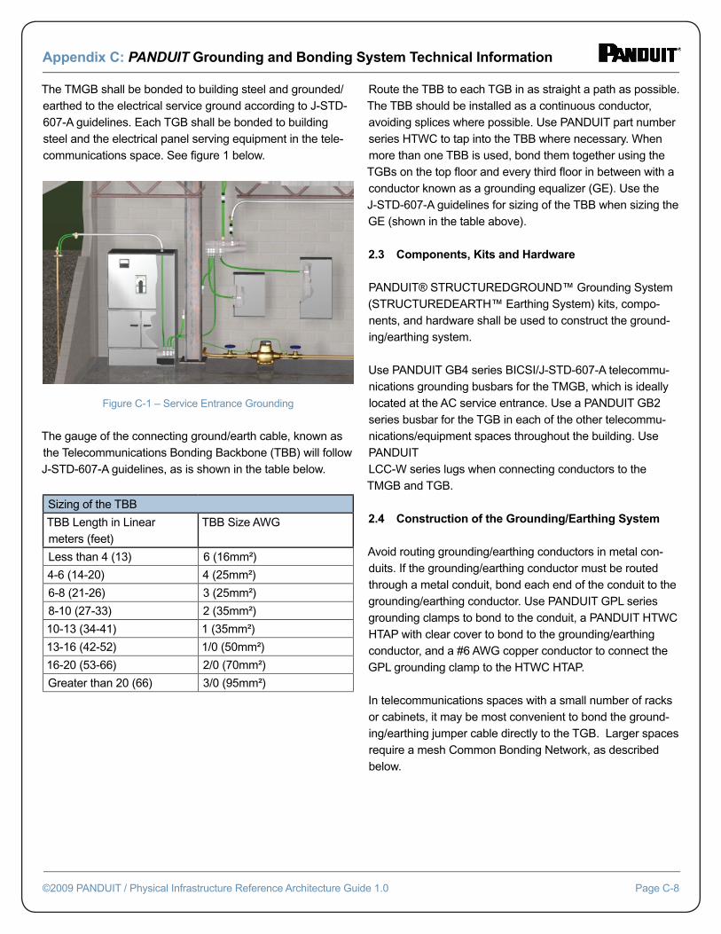
Appendix C: PANDUIT Grounding and Bonding System Technical Information
©2009 PANDUIT / Physical Infrastructure Reference Architecture Guide 1.0 Page C-8
The TMGB shall be bonded to building steel and grounded/earthed to the electrical service ground according to J-STD-607-A guidelines. Each TGB shall be bonded to building steel and the electrical panel serving equipment in the tele-communications space. See fi gure 1 below.
Figure C-1 – Service Entrance Grounding
The gauge of the connecting ground/earth cable, known as the Telecommunications Bonding Backbone (TBB) will follow J-STD-607-A guidelines, as is shown in the table below.
Sizing of the TBB
TBB Length in Linear meters (feet)
TBB Size AWG
Less than 4 (13) 6 (16mm²)
4-6 (14-20) 4 (25mm²)
6-8 (21-26) 3 (25mm²)
8-10 (27-33) 2 (35mm²)
10-13 (34-41) 1 (35mm²)
13-16 (42-52) 1/0 (50mm²)
16-20 (53-66) 2/0 (70mm²)
Greater than 20 (66) 3/0 (95mm²)
Route the TBB to each TGB in as straight a path as possible. The TBB should be installed as a continuous conductor, avoiding splices where possible. Use PANDUIT part number series HTWC to tap into the TBB where necessary. When more than one TBB is used, bond them together using the TGBs on the top fl oor and every third fl oor in between with a conductor known as a grounding equalizer (GE). Use the J-STD-607-A guidelines for sizing of the TBB when sizing the GE (shown in the table above).
2.3 Components, Kits and Hardware
PANDUIT® STRUCTUREDGROUND™ Grounding System (STRUCTUREDEARTH™ Earthing System) kits, compo-nents, and hardware shall be used to construct the ground-ing/earthing system.
Use PANDUIT GB4 series BICSI/J-STD-607-A telecommu-nications grounding busbars for the TMGB, which is ideally located at the AC service entrance. Use a PANDUIT GB2 series busbar for the TGB in each of the other telecommu-nications/equipment spaces throughout the building. Use PANDUIT LCC-W series lugs when connecting conductors to the TMGB and TGB.
2.4 Construction of the Grounding/Earthing System
Avoid routing grounding/earthing conductors in metal con-duits. If the grounding/earthing conductor must be routed through a metal conduit, bond each end of the conduit to the grounding/earthing conductor. Use PANDUIT GPL series grounding clamps to bond to the conduit, a PANDUIT HTWC HTAP with clear cover to bond to the grounding/earthing conductor, and a #6 AWG copper conductor to connect the GPL grounding clamp to the HTWC HTAP.
In telecommunications spaces with a small number of racks or cabinets, it may be most convenient to bond the ground-ing/earthing jumper cable directly to the TGB. Larger spaces require a mesh Common Bonding Network, as described below.
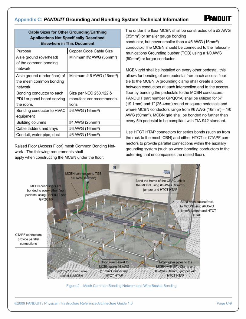
Appendix C: PANDUIT Grounding and Bonding System Technical Information
©2009 PANDUIT / Physical Infrastructure Reference Architecture Guide 1.0 Page C-9
Cable Sizes for Other Grounding/Earthing Applications Not Specifi cally Described
Elsewhere in This Document
Purpose Copper Code Cable Size
Aisle ground (overhead) of the common bonding network
Minimum #2 AWG (35mm²)
Aisle ground (under fl oor) of the mesh common bonding network
Minimum # 6 AWG (16mm²)
Bonding conductor to each PDU or panel board serving the room.
Size per NEC 250.122 & manufacturer recommenda-tions
Bonding conductor to HVAC equipment
#6 AWG (16mm²)
Building columns #4 AWG (25mm²)
Cable ladders and trays #6 AWG (16mm²)
Conduit, water pipe, duct #6 AWG (16mm²)
Raised Floor (Access Floor) mesh Common Bonding Net-work - The following requirements shallapply when constructing the MCBN under the fl oor:
The under the fl oor MCBN shall be constructed of a #2 AWG (35mm²) or smaller gauge bondingconductor, but never smaller than a #6 AWG (16mm²) conductor. The MCBN should be connected to the Telecom-munications Grounding busbar (TGB) using a 1/0 AWG (50mm²) or larger conductor.
MCBN grid shall be installed on every other pedestal, this allows for bonding of one pedestal from each access fl oor tile to the MCBN. A grounding clamp shall create a bond between conductors at each intersection and to the access fl oor by bonding the pedestals to the MCBN conductors. PANDUIT part number GPQC1/0 shall be utilized for ¾” (19.1mm) and 1” (25.4mm) round or square pedestals and where MCBN conductors range from #6 AWG (16mm²) – 1/0 AWG (50mm²). MCBN grid shall be bonded no further than every 5th pedestal to be compliant with TIA-942 standard.
Use HTCT HTAP connectors for series bonds (such as from the rack to the mesh CBN) and either HTCT or CTAPF con-nectors to provide parallel connections within the auxiliary grounding system (such as when bonding conductors to the outer ring that encompasses the raised fl oor).
Figure 2 – Mesh Common Bonding Network and Wire Basket Bonding
MCBN connection to TGB 1/0 AWG (50mm²)
MCBN conductors are bonded to every other fl oor
pedestal using PANDUIT part GPQC1/0
CTAPF connectors provide parallel
connections
Bond the frame of the CRAC unit to the MCBN using #6 AWG (16mm²)
jumper and HTCT HTAP
Bond each cabinet/rack to MCBN using #6 AWG
(16mm²) jumper and HTCT HTAP
SBCT3-C to bond wire basket to MCBN
Bond wire basket to MCBN using #6 AWG (16mm²) jumper and
HTCT HTAP
Bond water pipes to the MCBN with GPL Clamp and
#6 AWG (16mm²) jumper with HTCT HTAP
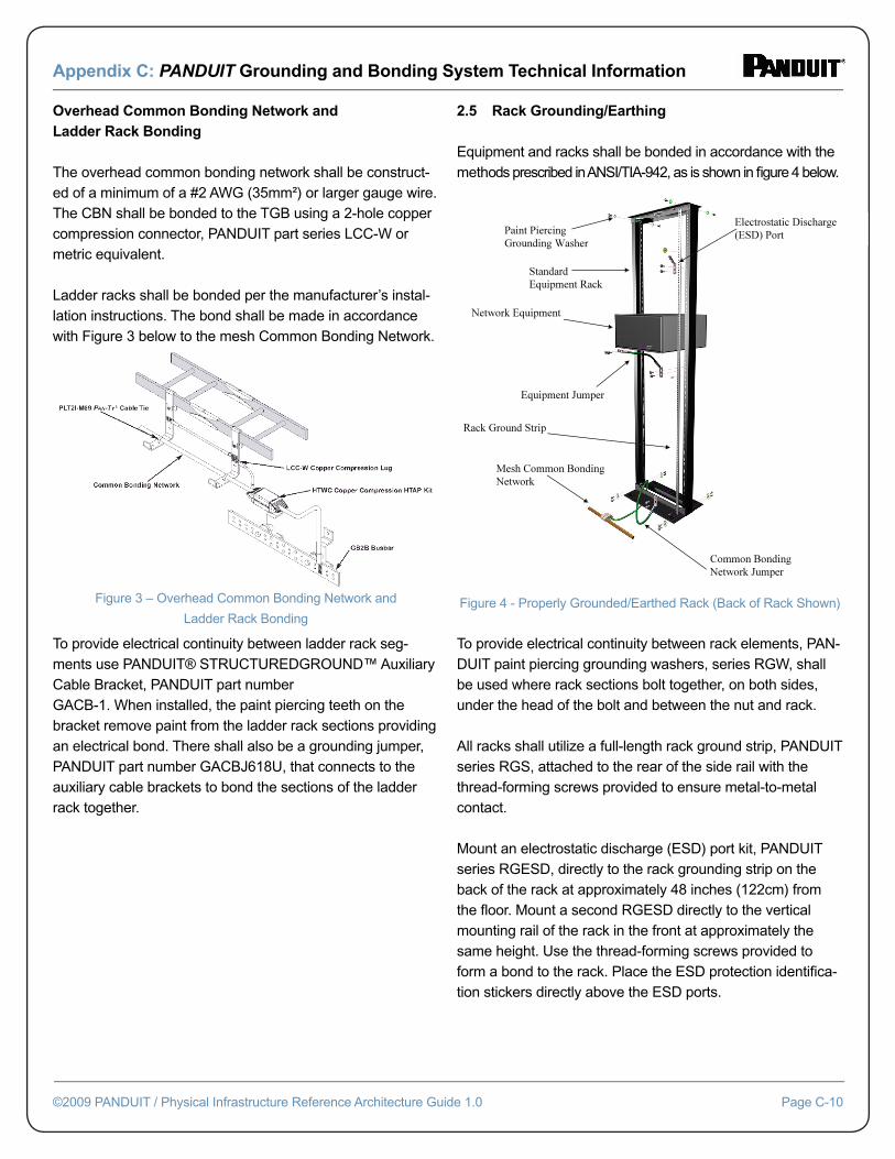
Appendix C: PANDUIT Grounding and Bonding System Technical Information
©2009 PANDUIT / Physical Infrastructure Reference Architecture Guide 1.0 Page C-10
Overhead Common Bonding Network and Ladder Rack Bonding
The overhead common bonding network shall be construct-ed of a minimum of a #2 AWG (35mm²) or larger gauge wire. The CBN shall be bonded to the TGB using a 2-hole copper compression connector, PANDUIT part series LCC-W or metric equivalent.
Ladder racks shall be bonded per the manufacturer’s instal-lation instructions. The bond shall be made in accordance with Figure 3 below to the mesh Common Bonding Network.
To provide electrical continuity between ladder rack seg-ments use PANDUIT® STRUCTUREDGROUND™ Auxiliary Cable Bracket, PANDUIT part numberGACB-1. When installed, the paint piercing teeth on the bracket remove paint from the ladder rack sections providing an electrical bond. There shall also be a grounding jumper, PANDUIT part number GACBJ618U, that connects to the auxiliary cable brackets to bond the sections of the ladder rack together.
2.5 Rack Grounding/Earthing
Equipment and racks shall be bonded in accordance with the methods prescribed in ANSI/TIA-942, as is shown in fi gure 4 below.
Figure 4 - Properly Grounded/Earthed Rack (Back of Rack Shown)
To provide electrical continuity between rack elements, PAN-DUIT paint piercing grounding washers, series RGW, shall be used where rack sections bolt together, on both sides, under the head of the bolt and between the nut and rack.
All racks shall utilize a full-length rack ground strip, PANDUIT series RGS, attached to the rear of the side rail with the thread-forming screws provided to ensure metal-to-metal contact.
Mount an electrostatic discharge (ESD) port kit, PANDUIT series RGESD, directly to the rack grounding strip on the back of the rack at approximately 48 inches (122cm) from the fl oor. Mount a second RGESD directly to the vertical mounting rail of the rack in the front at approximately the same height. Use the thread-forming screws provided to form a bond to the rack. Place the ESD protection identifi ca-tion stickers directly above the ESD ports.
Figure 3 – Overhead Common Bonding Network and
Ladder Rack Bonding
pp gg
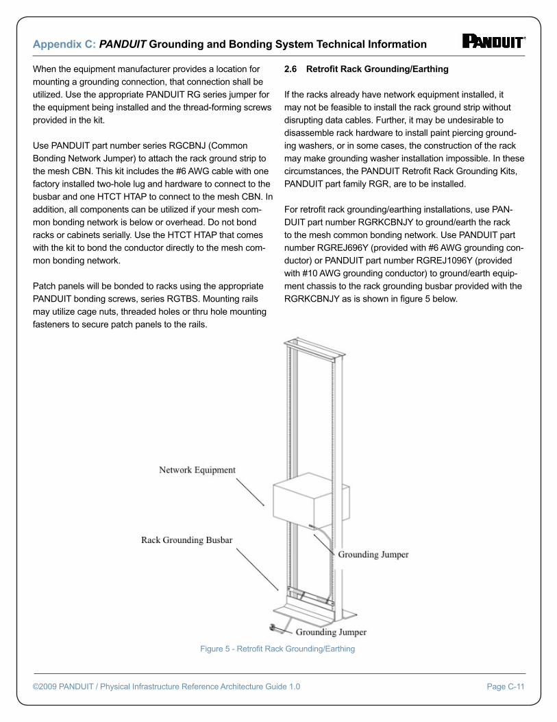
Appendix C: PANDUIT Grounding and Bonding System Technical Information
©2009 PANDUIT / Physical Infrastructure Reference Architecture Guide 1.0 Page C-11
When the equipment manufacturer provides a location for mounting a grounding connection, that connection shall be utilized. Use the appropriate PANDUIT RG series jumper for the equipment being installed and the thread-forming screws provided in the kit.
Use PANDUIT part number series RGCBNJ (Common Bonding Network Jumper) to attach the rack ground strip to the mesh CBN. This kit includes the #6 AWG cable with one factory installed two-hole lug and hardware to connect to the busbar and one HTCT HTAP to connect to the mesh CBN. In addition, all components can be utilized if your mesh com-mon bonding network is below or overhead. Do not bond racks or cabinets serially. Use the HTCT HTAP that comes with the kit to bond the conductor directly to the mesh com-mon bonding network.
Patch panels will be bonded to racks using the appropriate PANDUIT bonding screws, series RGTBS. Mounting rails may utilize cage nuts, threaded holes or thru hole mounting fasteners to secure patch panels to the rails.
2.6 Retrofi t Rack Grounding/Earthing
If the racks already have network equipment installed, it may not be feasible to install the rack ground strip without disrupting data cables. Further, it may be undesirable to disassemble rack hardware to install paint piercing ground-ing washers, or in some cases, the construction of the rack may make grounding washer installation impossible. In these circumstances, the PANDUIT Retrofi t Rack Grounding Kits, PANDUIT part family RGR, are to be installed.
For retrofi t rack grounding/earthing installations, use PAN-DUIT part number RGRKCBNJY to ground/earth the rack to the mesh common bonding network. Use PANDUIT part number RGREJ696Y (provided with #6 AWG grounding con-ductor) or PANDUIT part number RGREJ1096Y (provided with #10 AWG grounding conductor) to ground/earth equip-ment chassis to the rack grounding busbar provided with the RGRKCBNJY as is shown in fi gure 5 below.
Figure 5 - Retrofi t Rack Grounding/Earthing
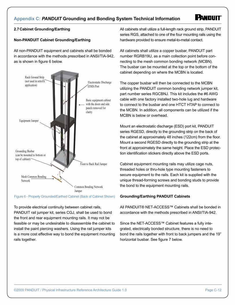
Appendix C: PANDUIT Grounding and Bonding System Technical Information
©2009 PANDUIT / Physical Infrastructure Reference Architecture Guide 1.0 Page C-12
2.7 Cabinet Grounding/Earthing
Non-PANDUIT Cabinet Grounding/Earthing
All non-PANDUIT equipment and cabinets shall be bonded in accordance with the methods prescribed in ANSI/TIA-942, as is shown in fi gure 6 below.
Figure 6 - Properly Grounded/Earthed Cabinet (Back of Cabinet Shown)
To provide electrical continuity between cabinet rails, PANDUIT rail jumper kit, series CGJ, shall be used to bond the front and rear equipment mounting rails. It may not be feasible or may be undesirable to disassemble the cabinet to install the paint piercing washers. Using the rail jumper kits is a more cost effective way to bond the equipment mounting rails together.
All cabinets shall utilize a full-length rack ground strip, PANDUIT series RGS, attached to one of the four mounting rails using the hardware provided to ensure metal-to-metal contact.
All cabinets shall utilize a copper busbar, PANDUIT part number RGRB19U, as a main collection point before con-necting to the mesh common bonding network (MCBN). The busbar can be mounted at the top or the bottom of the cabinet depending on where the MCBN is located.
The copper busbar will then be connected to the MCBN utilizing the PANDUIT common bonding network jumper kit, part number series RGCBNJ. This kit includes the #6 AWG cable with one factory installed two-hole lug and hardware to connect to the busbar and one HTCT HTAP to connect to the MCBN. In addition, all components can be utilized if the MCBN is below or overhead.
Mount an electrostatic discharge (ESD) port kit, PANDUIT series RGESD, directly to the grounding strip on the back of the cabinet at approximately 48 inches (122cm) from the fl oor. Mount a second RGESD directly to the grounding strip at the front at approximately the same height. Place the ESD protec-tion identifi cation stickers directly above the ESD ports.
Cabinet equipment mounting rails may utilize cage nuts, threaded holes or thru-hole type mounting fasteners to secure equipment to the rails. Each kit is supplied with the unique thread-forming screws and bonding studs to provide the bond to the equipment mounting rails.
Grounding/Earthing PANDUIT Cabinets
All PANDUIT® NET-ACCESS™ Cabinets shall be bonded in accordance with the methods prescribed in ANSI/TIA-942.
Since the NET-ACCESS™ Cabinet features a fully inte-grated, electrically bonded structure, there is no need to bond the rails together with front to back jumpers and the 19” horizontal busbar. See fi gure 7 below.
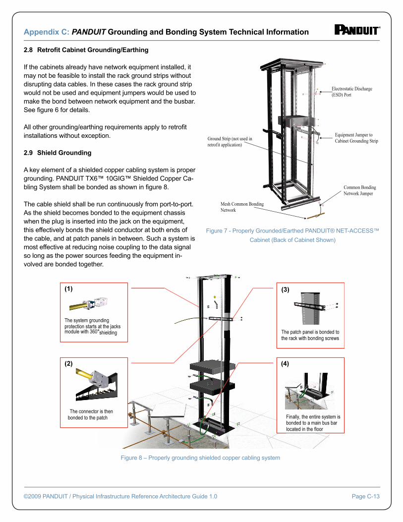
Appendix C: PANDUIT Grounding and Bonding System Technical Information
©2009 PANDUIT / Physical Infrastructure Reference Architecture Guide 1.0 Page C-13
2.8 Retrofi t Cabinet Grounding/Earthing
If the cabinets already have network equipment installed, it may not be feasible to install the rack ground strips without disrupting data cables. In these cases the rack ground strip would not be used and equipment jumpers would be used to make the bond between network equipment and the busbar. See fi gure 6 for details.
All other grounding/earthing requirements apply to retrofi t installations without exception.
2.9 Shield Grounding
A key element of a shielded copper cabling system is proper grounding. PANDUIT TX6™ 10GIG™ Shielded Copper Ca-bling System shall be bonded as shown in fi gure 8.
The cable shield shall be run continuously from port-to-port. As the shield becomes bonded to the equipment chassis when the plug is inserted into the jack on the equipment, this effectively bonds the shield conductor at both ends of the cable, and at patch panels in between. Such a system is most effective at reducing noise coupling to the data signal so long as the power sources feeding the equipment in-volved are bonded together.
Figure 7 - Properly Grounded/Earthed PANDUIT® NET-ACCESS™
Cabinet (Back of Cabinet Shown)
Figure 8 – Properly grounding shielded copper cabling system
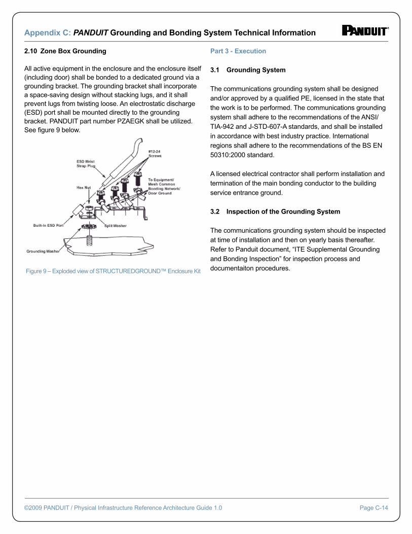
Appendix C: PANDUIT Grounding and Bonding System Technical Information
©2009 PANDUIT / Physical Infrastructure Reference Architecture Guide 1.0 Page C-14
2.10 Zone Box Grounding
All active equipment in the enclosure and the enclosure itself (including door) shall be bonded to a dedicated ground via a grounding bracket. The grounding bracket shall incorporate a space-saving design without stacking lugs, and it shall prevent lugs from twisting loose. An electrostatic discharge (ESD) port shall be mounted directly to the grounding bracket. PANDUIT part number PZAEGK shall be utilized. See fi gure 9 below.
Figure 9 – Exploded view of STRUCTUREDGROUND™ Enclosure Kit
Part 3 - Execution
3.1 Grounding System
The communications grounding system shall be designed and/or approved by a qualifi ed PE, licensed in the state that the work is to be performed. The communications grounding system shall adhere to the recommendations of the ANSI/TIA-942 and J-STD-607-A standards, and shall be installed in accordance with best industry practice. International regions shall adhere to the recommendations of the BS EN 50310:2000 standard.
A licensed electrical contractor shall perform installation and termination of the main bonding conductor to the building service entrance ground.
3.2 Inspection of the Grounding System
The communications grounding system should be inspected at time of installation and then on yearly basis thereafter. Refer to Panduit document, “ITE Supplemental Grounding and Bonding Inspection” for inspection process and documentaiton procedures.

Appendix C: PANDUIT Grounding and Bonding System Technical Information
©2009 PANDUIT / Physical Infrastructure Reference Architecture Guide 1.0 Page C-15
Appendix C-3: Example Grounding and Bonding SystemVisual Inspection and Documentation Process
Example of a Grounding Visual Inspection and Documentation Process
Date:
Company:
Contact:
This document describes the process of properly inspect-ing information technology equipment (ITE) supplemental grounding and bonding systems.
An answer of “yes” for each question on the inspection list indicates that the components of the ITE supplemental grounding and bonding system have been installed to com-monly referenced industry standards.
Use the room/rack/cabinet number space on each sheet to provide each measurement set with a unique identifi cation number so that issues found during the inspection can be addressed later.
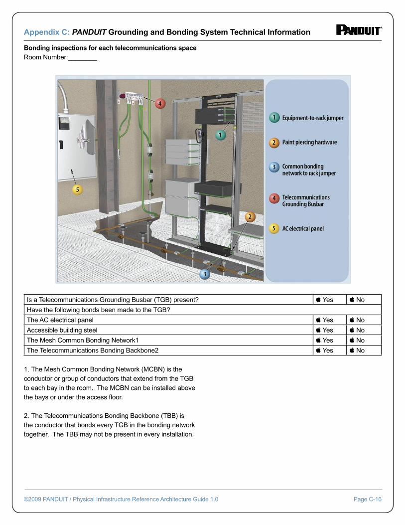
Appendix C: PANDUIT Grounding and Bonding System Technical Information
©2009 PANDUIT / Physical Infrastructure Reference Architecture Guide 1.0 Page C-16
Bonding inspections for each telecommunications spaceRoom Number:________
Is a Telecommunications Grounding Busbar (TGB) present? Yes No
Have the following bonds been made to the TGB?
The AC electrical panel Yes No
Accessible building steel Yes No
The Mesh Common Bonding Network1 Yes No
The Telecommunications Bonding Backbone2 Yes No
1. The Mesh Common Bonding Network (MCBN) is the conductor or group of conductors that extend from the TGB to each bay in the room. The MCBN can be installed above the bays or under the access fl oor.
2. The Telecommunications Bonding Backbone (TBB) is the conductor that bonds every TGB in the bonding network together. The TBB may not be present in every installation.
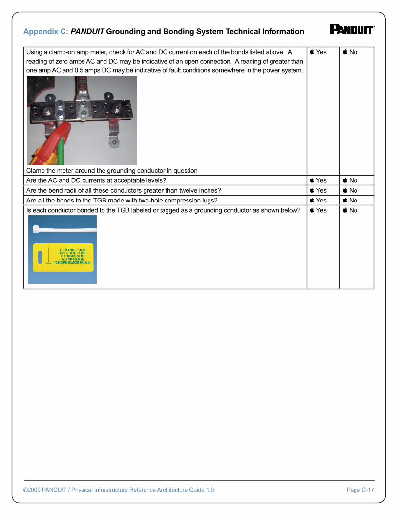
Appendix C: PANDUIT Grounding and Bonding System Technical Information
©2009 PANDUIT / Physical Infrastructure Reference Architecture Guide 1.0 Page C-17
Using a clamp-on amp meter, check for AC and DC current on each of the bonds listed above. A reading of zero amps AC and DC may be indicative of an open connection. A reading of greater than one amp AC and 0.5 amps DC may be indicative of fault conditions somewhere in the power system.
Clamp the meter around the grounding conductor in question
Yes No
Are the AC and DC currents at acceptable levels? Yes No
Are the bend radii of all these conductors greater than twelve inches? Yes No
Are all the bonds to the TGB made with two-hole compression lugs? Yes No
Is each conductor bonded to the TGB labeled or tagged as a grounding conductor as shown below?
Yes No
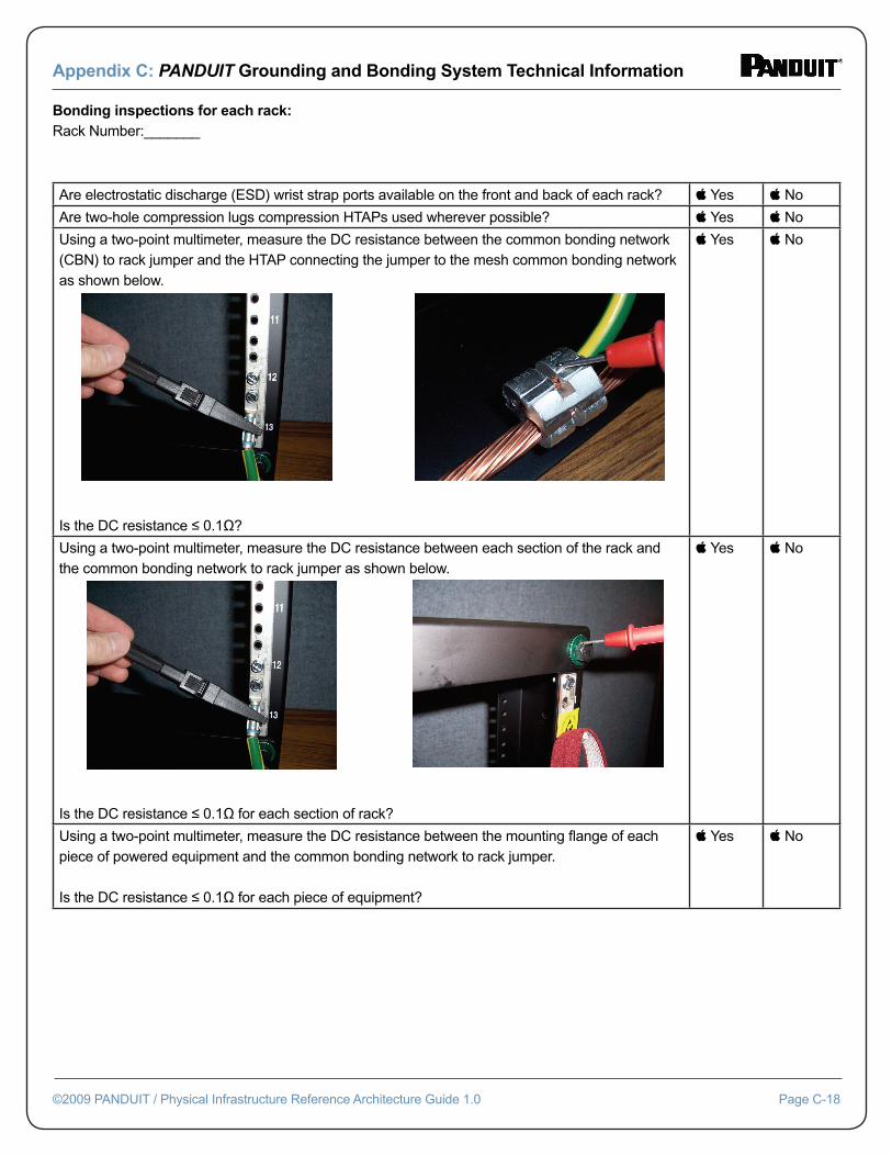
Appendix C: PANDUIT Grounding and Bonding System Technical Information
©2009 PANDUIT / Physical Infrastructure Reference Architecture Guide 1.0 Page C-18
Bonding inspections for each rack:Rack Number:_______
Are electrostatic discharge (ESD) wrist strap ports available on the front and back of each rack? Yes No
Are two-hole compression lugs compression HTAPs used wherever possible? Yes No
Using a two-point multimeter, measure the DC resistance between the common bonding network (CBN) to rack jumper and the HTAP connecting the jumper to the mesh common bonding network as shown below. One probe on the CBN jumper: One probe on the HTAP:
Is the DC resistance ≤ 0.1Ω?
Yes No
Using a two-point multimeter, measure the DC resistance between each section of the rack and the common bonding network to rack jumper as shown below. One probe on the CBN jumper: One probe on the washer:
Is the DC resistance ≤ 0.1Ω for each section of rack?
Yes No
Using a two-point multimeter, measure the DC resistance between the mounting fl ange of each piece of powered equipment and the common bonding network to rack jumper.
Is the DC resistance ≤ 0.1Ω for each piece of equipment?
Yes No
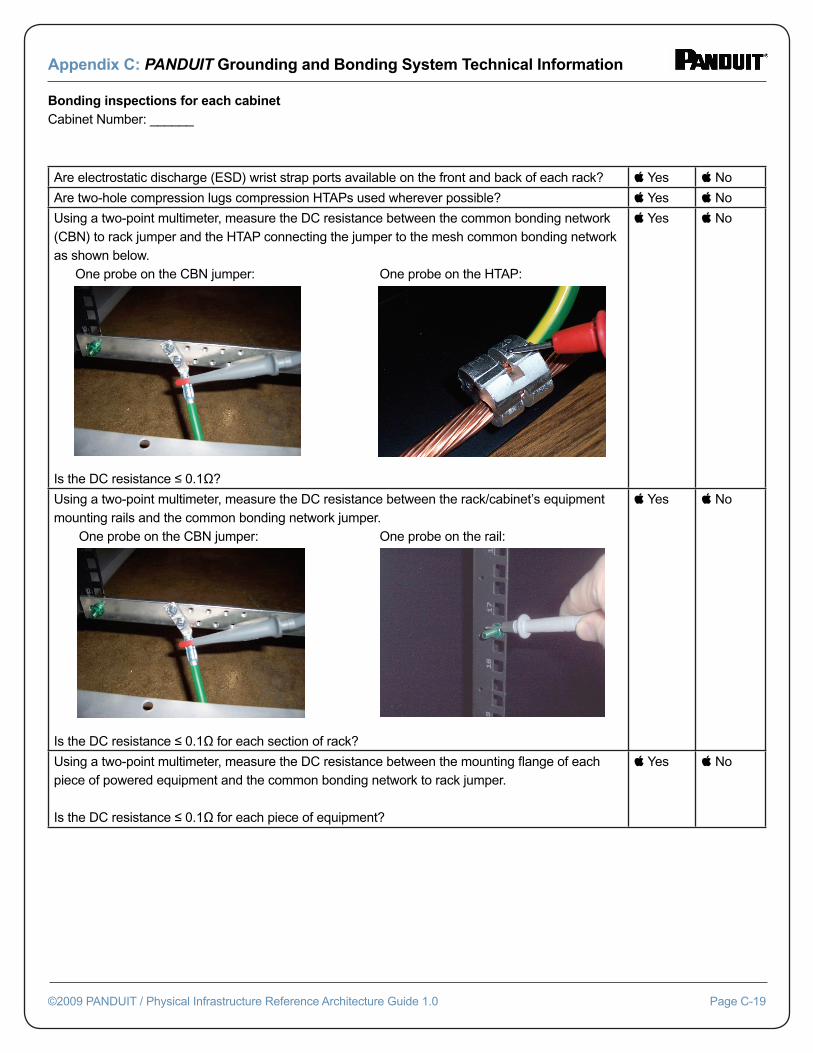
Appendix C: PANDUIT Grounding and Bonding System Technical Information
©2009 PANDUIT / Physical Infrastructure Reference Architecture Guide 1.0 Page C-19
Bonding inspections for each cabinetCabinet Number: ______
Are electrostatic discharge (ESD) wrist strap ports available on the front and back of each rack? Yes No
Are two-hole compression lugs compression HTAPs used wherever possible? Yes No
Using a two-point multimeter, measure the DC resistance between the common bonding network (CBN) to rack jumper and the HTAP connecting the jumper to the mesh common bonding network as shown below. One probe on the CBN jumper: One probe on the HTAP:
Is the DC resistance ≤ 0.1Ω?
Yes No
Using a two-point multimeter, measure the DC resistance between the rack/cabinet’s equipment mounting rails and the common bonding network jumper. One probe on the CBN jumper: One probe on the rail:
Is the DC resistance ≤ 0.1Ω for each section of rack?
Yes No
Using a two-point multimeter, measure the DC resistance between the mounting fl ange of each piece of powered equipment and the common bonding network to rack jumper.
Is the DC resistance ≤ 0.1Ω for each piece of equipment?
Yes No
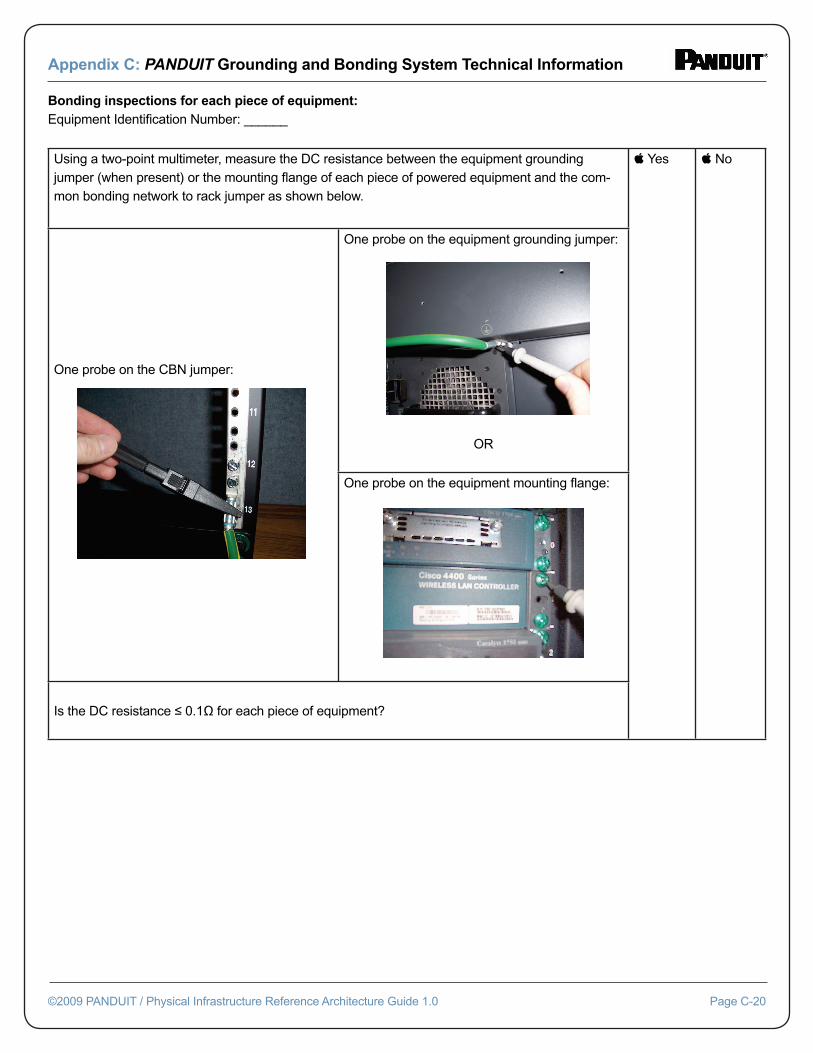
Appendix C: PANDUIT Grounding and Bonding System Technical Information
©2009 PANDUIT / Physical Infrastructure Reference Architecture Guide 1.0 Page C-20
Bonding inspections for each piece of equipment:Equipment Identifi cation Number: ______
Using a two-point multimeter, measure the DC resistance between the equipment grounding jumper (when present) or the mounting fl ange of each piece of powered equipment and the com-mon bonding network to rack jumper as shown below.
Yes No
One probe on the CBN jumper:
One probe on the equipment grounding jumper:
OR
One probe on the equipment mounting fl ange:
Is the DC resistance ≤ 0.1Ω for each piece of equipment?
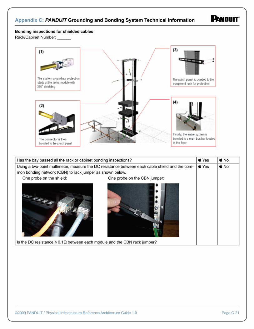
Appendix C: PANDUIT Grounding and Bonding System Technical Information
©2009 PANDUIT / Physical Infrastructure Reference Architecture Guide 1.0 Page C-21
Bonding inspections for shielded cablesRack/Cabinet Number: ______
Has the bay passed all the rack or cabinet bonding inspections? Yes No
Using a two-point multimeter, measure the DC resistance between each cable shield and the com-mon bonding network (CBN) to rack jumper as shown below. One probe on the shield: One probe on the CBN jumper:
Is the DC resistance ≤ 0.1Ω between each module and the CBN rack jumper?
Yes No
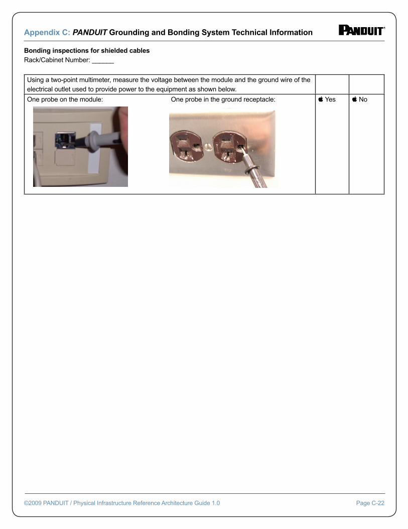
Appendix C: PANDUIT Grounding and Bonding System Technical Information
©2009 PANDUIT / Physical Infrastructure Reference Architecture Guide 1.0 Page C-22
Bonding inspections for shielded cablesRack/Cabinet Number: ______
Using a two-point multimeter, measure the voltage between the module and the ground wire of the electrical outlet used to provide power to the equipment as shown below.
One probe on the module: One probe in the ground receptacle: Yes No