Embed Size (px)
Citation preview
! "# $ " % & " ' $
APPENDIX CHYDRAULIC CEMENT CONCRETE SPECIFICATIONS
Speci! cation Index
Division II - Materials
Section Title Page
201 Mineral Filler 3202 Fine Aggregate 3 - 5203 Coarse Aggregate 5 - 9206 Lightweight Aggregate 10214 Hydraulic Cement 10215 Concrete Admixtures 11216 Water for Use with Cement or Lime 12217 Hydraulic Cement Concrete 12 - 24220 Concrete Curing Materials 24 - 25223 Steel Reinforcement 25 - 26241 Fly Ash 26
Division III - Roadway Construction
316 Hydraulic Cement Concrete Pavement 28 - 40
Division IV - Bridges and Structures
401 Structure Excavation 42 - 46404 Hydraulic Cement Concrete Operations 46 - 65406 Reinforcing Steel 65 - 68410 Railing and Parapets 68 - 71412 Widening, Repairing, and Reconstructing 71 - 82
Existing Structures
Division V - Incidental Construction
502 Incidental Concrete Items 84 - 90509 Patching Hydraulic Cement Concrete Pavement 91 - 93
Note: These speci! cations are for training purposes only. Do not use them in the ! eld or on a project. Contact VDOT - Construction Division for an up to date Road and Bridge Speci! cation Book.
! " " # $ % & $ ' #
Division II
Materials
! "# $ % & ' % ( $
SECTION 201--MINERAL FILLER
201.01--Description.
These speci! cations cover inorganic material such as lime or " y ash, usually of very ! ne grading, added to soil or asphalt to produce a desired effect.
201.02--Detail Requirements.
Mineral ! ller shall conform to the requirements of AASHTO M17. Tests will be performed in accordance with the requirements of AASHTO T37.
SECTION 202--FINE AGGREGATE
202.01--Description.
These speci! cations cover material for use as ! ne aggregate in hydraulic cement concrete, mortar, asphalt concrete, and asphalt surface treatments.
202.02--Materials.
Fine aggregate is classi! ed herein in accordance with its occurrence or method of manufacture as natural sand or stone sand. Natural sand shall consist of grains of hard, sound material, predominantly quartz, occurring in natural deposits or in loosely bound deposits, such as sandstone conglomerate. Stone sand shall consist of sound crushed particles of approved Grade A stone, essentially free from " at or elongated pieces, with sharp edges and corners removed.
Fine aggregates for use in hydraulic cement concrete that are obtained from more than one source shall not be used alternately or mixed without the consent of the Engineer.
202.03--Detail Requirements.
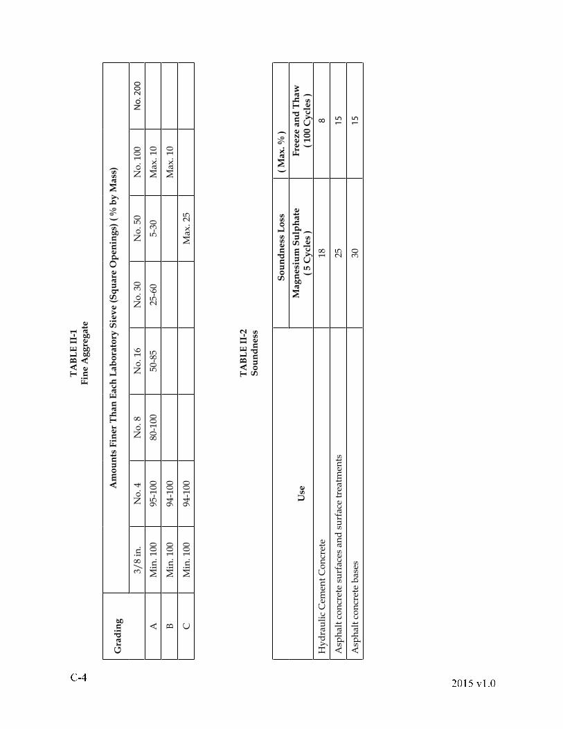
(a) Grading: Grading shall conform to the requirements of Table II-1. Tests will be performed in accordance with the requirements of AASHTO T27.
(b) Soundness: Soundness shall conform to the requirements of Table II-2. Tests will be performed in accordance with the requirements of AASHTO T103 or T104.
! " # $ % & ' % ( $
TA
BL
E I
I-1
Fin
e A
gg
reg
ate
Gra
din
gA
mo
un
ts F
iner
Th
an
Each
Lab
ora
tory
Sie
ve (
Sq
uare
Op
en
ing
s) (
% b
y M
ass
)
3/8
in.
No
. 4N
o. 8
No
. 16
No
. 30
No
. 50
No
. 100
No
. 2
00
AM
in. 1
0095
-100
80-1
0050
-85
25-6
05-
30M
ax. 1
0
BM
in. 1
0094
-100
Max
. 10
CM
in. 1
0094
-100
Max
. 25
TA
BL
E I
I-2
So
un
dn
ess
S
ou
nd
ness
Lo
ss
( M
ax. %
)
Use
Mag
nesi
um
Su
lph
ate
( 5 C
ycl
es
)F
reeze a
nd
Th
aw
( 100 C
ycl
es
)
Hy
dra
uli
c C
emen
t C
on
cret
e18
8
Asp
hal
t co
ncr
ete
surf
aces
an
d s
urf
ace
trea
tmen
ts25
15
Asp
hal
t co
ncr
ete
bas
es30
15
! "# $ % " & % ' $
(c) Organic Impurities: When ! ne aggregate is to be used in hydraulic cement concrete, the percentage of organic impurities shall conform to the requirements of AASHTO T21; however, material producing a darker color than that speci! ed in AASHTO T21 may be accepted in accordance with the requirements of AASHTO M6.
(d) Void Content: Void content will be tested in accordance with the requirements of VTM-5.
(e) Deleterious Material: The amount of deleterious material in sands shall be not more than the following:
AASHTO Material % by Mass Test Method Clay lumps 0.25 T112
Shale, mica, coated 1.0 T113 grains, soft or " aky particles
Organic material 0 T21
Total material passing T11 and No. 200 sieve by T27 washing1
For use in concrete 3 subject to abrasion
For other concrete 5
1In the case of stone sand, if the material passing the No. 200 sieve is dust of fracture, essentially free from clay or shale, the percentages shown for use in concrete subject to abrasion and in other concrete may be increased to 5.0% and 7.0%, respectively.
SECTION 203--COARSE AGGREGATE
203.01--Description.
These speci! cations cover material for use as coarse aggregate in hydraulic cement concrete, asphalt concrete, asphalt surface treatments, and drainage.
203.02--Materials.
Coarse aggregate shall consist of crushed stone, crushed slag, or crushed or uncrushed gravel with clean, hard, tough, and durable pieces free from adherent coatings and deleterious amounts of friable, thin, elongated, or laminated pieces; soluble salts; or organic materials.
! " # $ % & ' % ( $
(a) Crushed hydraulic cement concrete will be permitted for use as a coarse aggregate provided it conforms to the physical requirements speci! ed herein and shows no adverse chemical reaction. Crushed hydraulic cement concrete will not be permitted in the following: (1) reinforced cement concrete (2) in combination with other materials in contact with geotextile fabric when such fabric is used as a drainage item and (3) in back! ll or bedding for perforated pipe.
(b) Crushed gravel shall consist of particles of which at least 80 percent by weight shall have at least one face fractured by arti! cial crushing. Tests will be performed in accordance with the requirements of VTM-15.
(c) Blast furnace slag shall be relatively free from foreign minerals and glassy or spongy pieces. It shall have a dry rodded unit mass of at least 70 pounds per cubic foot for size No. 68 and smaller, and at least 65 pounds per cubic foot for larger sizes. Tests will be performed in accordance with the requirements of AASHTO T19. When used in asphalt surface treatments, blast furnace slag shall not contain more than 10 percent nonporous material and shall have an absorption of at least 3 percent. Tests will be performed in accordance with the requirements of AASHTO T85.
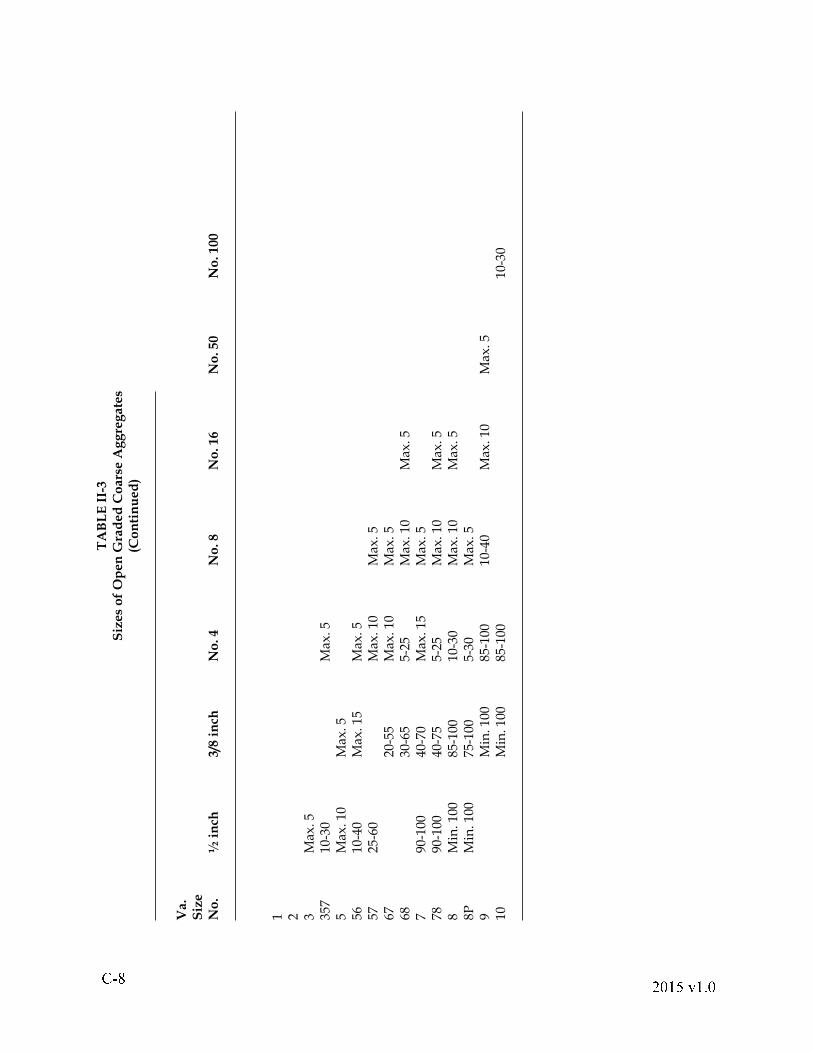
203.03--Detail Requirements.
(a) Grading: Open graded aggregates shall conform to the requirements of Table II-3. Tests will be performed in accordance with the requirements of AASHTO T27.
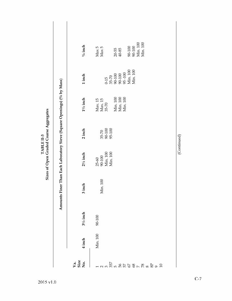
!" # $ % & $ ' # T
AB
LE
II-
3
Siz
es
of
Op
en
Gra
ded
Co
ars
e A
gg
reg
ate
s
Am
ou
nts
Fin
er
Th
an
Each
Lab
ora
tory
Sie
ve (
Sq
uare
Op
en
ing
s) (
% b
y M
ass
)
Va.
Siz
eN
o.
4 i
nch
3½
in
ch
3 i
nch
2½
in
ch
2 i
nch
1½
in
ch
1 i
nch
¾
in
ch 1
Min
. 100
90
-100
25-6
0
Max
. 15
M
ax 5
2
M
in. 1
00
90-1
00
35-7
0 M
ax. 1
5
Max
53
M
in. 1
00
90-1
00
35-7
0 0-
15
357
M
in. 1
00
95-1
00
35
-70
5
Min
. 100
90
-100
20
-55
56
M
in. 1
00
90-1
00
40-8
557
Min
. 100
95
-10
067
M
in. 1
00
90-1
0068
M
in. 1
00
90-1
007
M
in. 1
0078
Min
. 100
8 8P 9 10 (C
on
tin
ued
)
! " # $ % & ' % ( $
TA
BL
E I
I-3
Siz
es
of
Op
en
Gra
ded
Co
ars
e A
gg
reg
ate
s(C
on
tin
ued
)
Va.
Siz
eN
o.
½ i
nch
3
/8 i
nch
N
o. 4
No
. 8
No
. 16
No
. 50
No
. 100
1 2 3 M
ax. 5
357
10-3
0
Max
. 55
Max
. 10
Max
. 556
10
-40
Max
. 15
Max
. 557
25
-60
M
ax. 1
0 M
ax. 5
67
20
-55
Max
. 10
Max
. 568
30-6
5 5-
25
Max
. 10
Max
. 57
90-1
00
40-7
0 M
ax. 1
5 M
ax. 5
78
90-1
00
40-7
5 5-
25
Max
. 10
Max
. 58
Min
. 100
85
-100
10
-30
Max
. 10
Max
. 58P
M
in. 1
00
75-1
00
5-30
M
ax. 5
9
Min
. 100
85
-100
10
-40
Max
. 10
Max
. 510
Min
. 100
85
-100
10-3
0
! "# $ % & ' % ( $
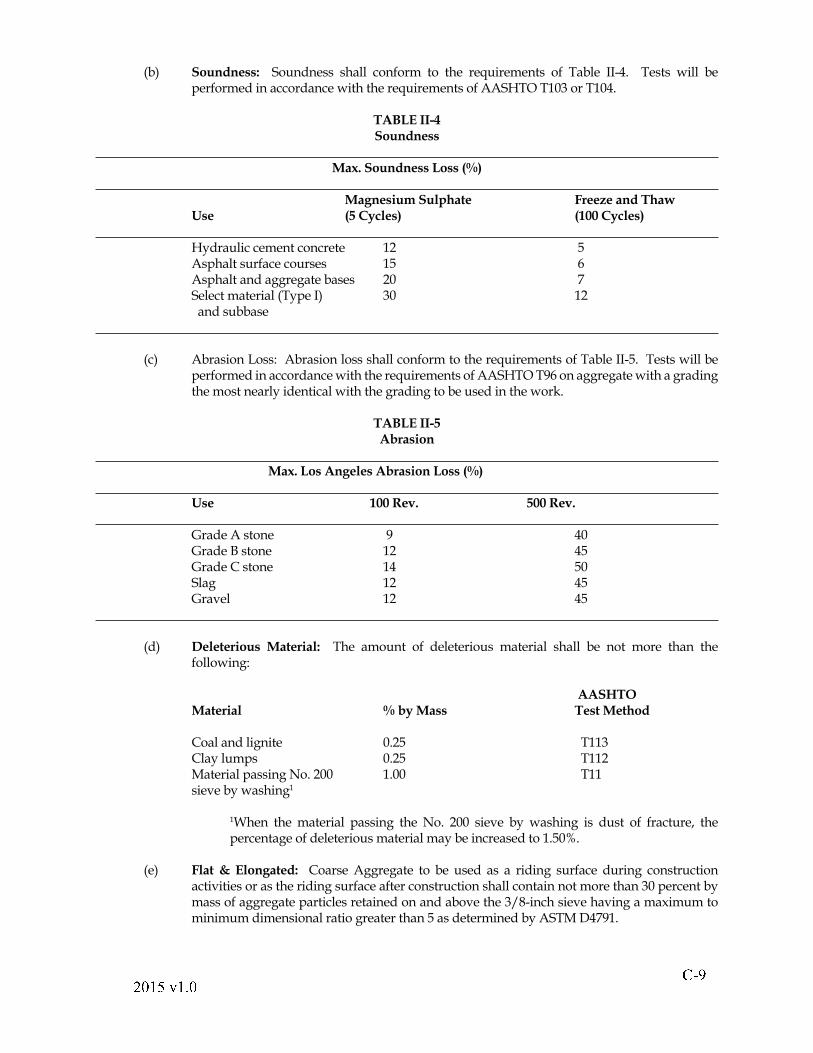
(b) Soundness: Soundness shall conform to the requirements of Table II-4. Tests will be performed in accordance with the requirements of AASHTO T103 or T104.
TABLE II-4 Soundness Max. Soundness Loss (%) Magnesium Sulphate Freeze and Thaw Use (5 Cycles) (100 Cycles) Hydraulic cement concrete 12 5 Asphalt surface courses 15 6 Asphalt and aggregate bases 20 7 Select material (Type I) 30 12 and subbase
(c) Abrasion Loss: Abrasion loss shall conform to the requirements of Table II-5. Tests will be performed in accordance with the requirements of AASHTO T96 on aggregate with a grading the most nearly identical with the grading to be used in the work.
TABLE II-5 Abrasion Max. Los Angeles Abrasion Loss (%) Use 100 Rev. 500 Rev. Grade A stone 9 40 Grade B stone 12 45 Grade C stone 14 50 Slag 12 45 Gravel 12 45
(d) Deleterious Material: The amount of deleterious material shall be not more than the following:
AASHTO Material % by Mass Test Method
Coal and lignite 0.25 T113 Clay lumps 0.25 T112 Material passing No. 200 1.00 T11 sieve by washing1
1When the material passing the No. 200 sieve by washing is dust of fracture, the percentage of deleterious material may be increased to 1.50%.
(e) Flat & Elongated: Coarse Aggregate to be used as a riding surface during construction activities or as the riding surface after construction shall contain not more than 30 percent by mass of aggregate particles retained on and above the 3/8-inch sieve having a maximum to minimum dimensional ratio greater than 5 as determined by ASTM D4791.
! " # $ # " % & " ' #
SECTION 206--LIGHTWEIGHT AGGREGATE
206.01--Description.
These speci! cations cover lightweight aggregate used in hydraulic cement concrete and asphalt surface treatment.
206.02--Detail Requirements.
Lightweight aggregate shall consist of clay, shale, or slate expanded through a sintering or rotary kiln.
(a) Lightweight aggregate used in hydraulic cement concrete shall conform to the requirements of AASHTO M195.
(b) Lightweight aggregate used for asphalt surface treatment shall conform to the requirements of AASHTO M195 except that Sections 3, 6, and 8 will not apply. Grading shall conform to the requirements of Table II-3 except that the maximum percentage by weight of material passing the No. 8 sieve shall be 16 percent and passing the No. 16 sieve shall be 9 percent.
SECTION 214--HYDRAULIC CEMENT214.01--Description.
These speci! cations cover cements that harden when mixed with water. The various types have special characteristics to be used as denoted in other parts of these speci! cations.
214.02--Detail Requirements.
(a) Blended hydraulic cement shall conform to the requirements of AASHTO M240, Type I(P) or Type I(S).
(b) Portland cements shall conform to the requirements of AASHTO M85 except as follows:
1. The SO3 content as speci! ed in AASHTO M85 will be permitted, provided the supporting data
speci! ed in AASHTO M85 are submitted to the Department for review and acceptance prior to use of the material.
(c) Expansive hydraulic cement shall conform to the requirements of ASTM C 845 Type K. SECTION 215--HYDRAULIC CEMENT CONCRETE ADMIXTURES
215.01--Description.
These speci! cations cover materials that are chemical or organic elements that may be added to a concrete mixture, when permitted elsewhere in these speci! cations, to achieve some desired effect.
215.02--Materials.
(a) Air-entraining admixtures shall conform to the requirements of AASHTO M154.
(b) Water-reducing and retarding admixtures shall conform to the requirements of AASHTO M194, Type D, and shall be free from water-soluble chlorides.
! " "# $ " % & " ' $
Use of water-reducing and retarding admixtures that have not been tested for compatibility with the brand, type, source, and quantity of cement proposed for use will not be permitted until tests have been performed in accordance with the requirements of VTM 16 and the test results conform to the requirements of Table I therein.
(c) Water-reducing admixtures shall conform to the requirements of AASHTO M194, Type A, and shall be free from water-soluble chlorides.
(d) Accelerating admixtures shall conform to the requirements of AASHTO M194, Type C or E.
(e) High-range water-reducing and high-range water-reducing and retarding admixtures shall conform to the requirements of AASHTO M194, Type F or G, and shall be free from water-soluble chlorides.
(f) Calcium chloride shall conform to the requirements of AASHTO M144, Type 2.
(g) Pozzolans shall conform to the requirements of Section 241 of the Speci! cations.
(h) Granulated iron blast-furnace slag shall conform to the requirements of ASTM C989, Grade 100 or 120.
(i) Silica Fume shall conform to the requirements of AASHTO M307.
(j) Corrosion Inhibitor shall contain a minimum 30 percent solution of calcium nitrite or other approved material.
(k) Metakaolin shall conform to the requirements of AASHTO M321.
215.03--Detail Requirements.
Approved admixture(s) shall be used in concrete in the proportions recommended by the manufacturer to obtain the optimum effect where seasonal, atmospheric, or job conditions dictate its use.
Only admixtures (a) through (e) that appear on the Department�s approved list shall be used. Initial approval will be based on independent laboratory data submitted by the manufacturer. Following initial approval of concrete admixtures, the manufacturer shall annually certify to the Engineer in writing that the material currently being furnished is identical in both composition and chemical concentrations with the material for which the laboratory tests were performed. If the Contractor proposes to use an admixture that differs in concentration from the acceptance sample, a certi! cate will be required from the manufacturer stating that the material is essentially the same in chemical composition as the approved mixture.
When placing concrete by pumping is authorized, the use of pump-aid admixtures approved by the Department will be allowed provided they are used in accordance with the manufacturer�s recommendations.
SECTION 216--WATER FOR USE WITH CEMENT OR LIME
216.01--Description.
These speci! cations cover water for use in mixing with cement or lime.
216.02--Detail Requirements.
Water shall be clean, clear, and free from oil, acid, salt, alkali, organic matter, or other deleterious substances.
! " # # $ " % & " ' $
Water that has been approved for drinking purposes may be accepted without testing for use in hydraulic cement concrete, cement, or lime stabilization. Water from other sources and pumping methods shall be approved by the Engineer before use.
The acidity or alkalinity of water will be determined colorimetrically or electrometrically. Water shall have a pH between 4.5 and 8.5. When subjected to the mortar test in accordance with the requirements of AASHTO T26, water shall produce a mortar having a compressive strength of at least 90 percent of a mortar of the same design using distilled water.
Wash water from hydraulic cement concrete mixer operations will be permitted to be reused in the concrete mixture provided it is metered and is 25 percent or less of the total water. The total water shall conform to the acceptance criteria of ASTM C1602, Tables 1 and 2. A uniform amount of wash water shall be used in consecutive batches, with subsequent admixture rates adjusted accordingly to produce a workable concrete conforming to the speci! cations.
SECTION 217--HYDRAULIC CEMENT CONCRETE
217.01--Description.
These speci! cations cover materials, design criteria, and mixing and testing procedures for hydraulic cement concrete.
217.02--Materials.
Hydraulic cement concrete shall consist of hydraulic cement, ! ne aggregate, coarse aggregate, water, and admixture(s) mixed in the approved proportions for the various classes of concrete by one of the methods designated hereinafter.
The Contractor shall be responsible for the quality control and condition of materials during handling, blending, and mixing operations and for the initial determination and necessary adjustments in the proportioning of materials used to produce the concrete.
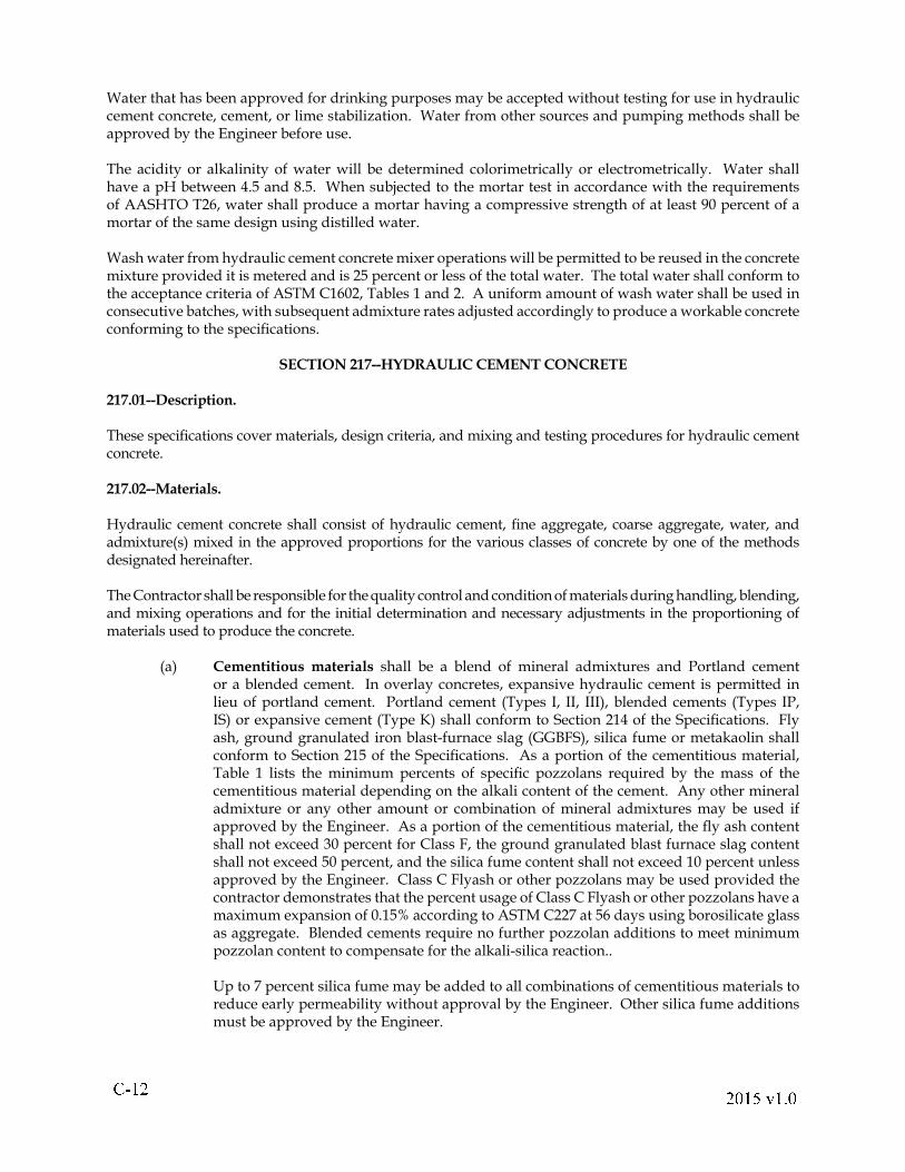
(a) Cementitious materials shall be a blend of mineral admixtures and Portland cement or a blended cement. In overlay concretes, expansive hydraulic cement is permitted in lieu of portland cement. Portland cement (Types I, II, III), blended cements (Types IP, IS) or expansive cement (Type K) shall conform to Section 214 of the Speci! cations. Fly ash, ground granulated iron blast-furnace slag (GGBFS), silica fume or metakaolin shall conform to Section 215 of the Speci! cations. As a portion of the cementitious material, Table 1 lists the minimum percents of speci! c pozzolans required by the mass of the cementitious material depending on the alkali content of the cement. Any other mineral admixture or any other amount or combination of mineral admixtures may be used if approved by the Engineer. As a portion of the cementitious material, the " y ash content shall not exceed 30 percent for Class F, the ground granulated blast furnace slag content shall not exceed 50 percent, and the silica fume content shall not exceed 10 percent unless approved by the Engineer. Class C Flyash or other pozzolans may be used provided the contractor demonstrates that the percent usage of Class C Flyash or other pozzolans have a maximum expansion of 0.15% according to ASTM C227 at 56 days using borosilicate glass as aggregate. Blended cements require no further pozzolan additions to meet minimum pozzolan content to compensate for the alkali-silica reaction..
Up to 7 percent silica fume may be added to all combinations of cementitious materials to reduce early permeability without approval by the Engineer. Other silica fume additions must be approved by the Engineer.
! " #$ % " & ' " ( %
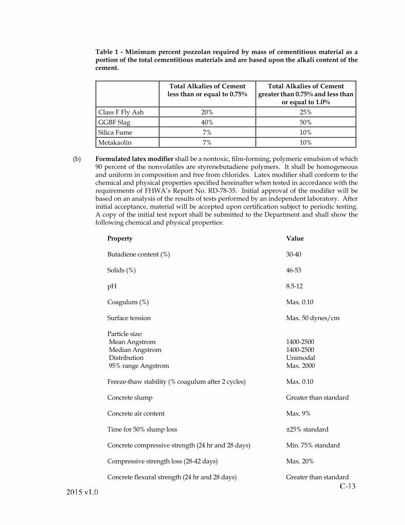
Table 1 - Minimum percent pozzolan required by mass of cementitious material as a portion of the total cementitious materials and are based upon the alkali content of the cement.
Total Alkalies of Cementless than or equal to 0.75%
Total Alkalies of Cementgreater than 0.75% and less than
or equal to 1.0%
Class F Fly Ash 20% 25%
GGBF Slag 40% 50%
Silica Fume 7% 10%
Metakaolin 7% 10%
(b) Formulated latex modi! er shall be a nontoxic, ! lm-forming, polymeric emulsion of which 90 percent of the nonvolatiles are styrenebutadiene polymers. It shall be homogeneous and uniform in composition and free from chlorides. Latex modi! er shall conform to the chemical and physical properties speci! ed hereinafter when tested in accordance with the requirements of FHWA�s Report No. RD-78-35. Initial approval of the modi! er will be based on an analysis of the results of tests performed by an independent laboratory. After initial acceptance, material will be accepted upon certi! cation subject to periodic testing. A copy of the initial test report shall be submitted to the Department and shall show the following chemical and physical properties:
Property Value
Butadiene content (%) 30-40
Solids (%) 46-53
pH 8.5-12
Coagulum (%) Max. 0.10
Surface tension Max. 50 dynes/cm
Particle size: Mean Angstrom 1400-2500 Median Angstrom 1400-2500 Distribution Unimodal 95% range Angstrom Max. 2000
Freeze-thaw stability (% coagulum after 2 cycles) Max. 0.10 Concrete slump Greater than standard Concrete air content Max. 9%
Time for 50% slump loss ±25% standard
Concrete compressive strength (24 hr and 28 days) Min. 75% standard Compressive strength loss (28-42 days) Max. 20% Concrete " exural strength (24 hr and 28 days) Greater than standard
! " # $ % " & ' " ( %
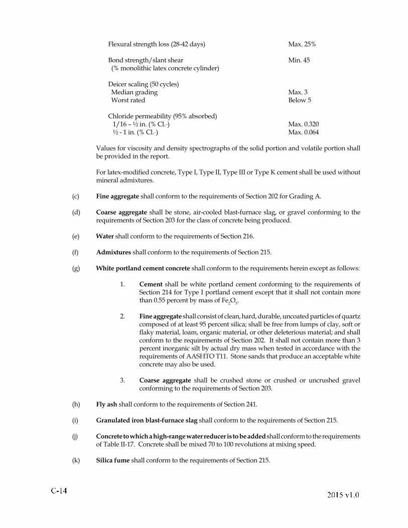
Flexural strength loss (28-42 days) Max. 25% Bond strength/slant shear Min. 45 (% monolithic latex concrete cylinder) Deicer scaling (50 cycles) Median grading Max. 3 Worst rated Below 5
Chloride permeability (95% absorbed) 1/16 � ½ in. (% Cl._) Max. 0.320 ½ - 1 in. (% Cl._) Max. 0.064 Values for viscosity and density spectrographs of the solid portion and volatile portion shall
be provided in the report.
For latex-modi! ed concrete, Type I, Type II, Type III or Type K cement shall be used without mineral admixtures.
(c) Fine aggregate shall conform to the requirements of Section 202 for Grading A.
(d) Coarse aggregate shall be stone, air-cooled blast-furnace slag, or gravel conforming to the requirements of Section 203 for the class of concrete being produced.
(e) Water shall conform to the requirements of Section 216.
(f) Admixtures shall conform to the requirements of Section 215.
(g) White portland cement concrete shall conform to the requirements herein except as follows:
1. Cement shall be white portland cement conforming to the requirements of Section 214 for Type I portland cement except that it shall not contain more than 0.55 percent by mass of Fe
2O
3.
2. Fine aggregate shall consist of clean, hard, durable, uncoated particles of quartz composed of at least 95 percent silica; shall be free from lumps of clay, soft or " aky material, loam, organic material, or other deleterious material; and shall conform to the requirements of Section 202. It shall not contain more than 3 percent inorganic silt by actual dry mass when tested in accordance with the requirements of AASHTO T11. Stone sands that produce an acceptable white concrete may also be used.
3. Coarse aggregate shall be crushed stone or crushed or uncrushed gravel conforming to the requirements of Section 203.
(h) Fly ash shall conform to the requirements of Section 241.
(i) Granulated iron blast-furnace slag shall conform to the requirements of Section 215.
(j) Concrete to which a high-range water reducer is to be added shall conform to the requirements of Table II-17. Concrete shall be mixed 70 to 100 revolutions at mixing speed.
(k) Silica fume shall conform to the requirements of Section 215.
! " #$ % " # & " ' %
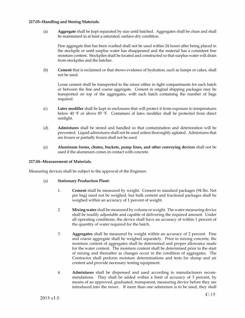
217.03--Handling and Storing Materials.
(a) Aggregate shall be kept separated by size until batched. Aggregates shall be clean and shall be maintained in at least a saturated, surface-dry condition.
Fine aggregate that has been washed shall not be used within 24 hours after being placed in the stockpile or until surplus water has disappeared and the material has a consistent free moisture content. Stockpiles shall be located and constructed so that surplus water will drain from stockpiles and the batcher.
(b) Cement that is reclaimed or that shows evidence of hydration, such as lumps or cakes, shall not be used.
Loose cement shall be transported to the mixer either in tight compartments for each batch or between the ! ne and coarse aggregate. Cement in original shipping packages may be transported on top of the aggregates, with each batch containing the number of bags required.
(c) Latex modi! er shall be kept in enclosures that will protect it from exposure to temperatures below 40 oF or above 85 oF. Containers of latex modi! er shall be protected from direct sunlight.
(d) Admixtures shall be stored and handled so that contamination and deterioration will be prevented. Liquid admixtures shall not be used unless thoroughly agitated. Admixtures that are frozen or partially frozen shall not be used.
(e) Aluminum forms, chutes, buckets, pump lines, and other conveying devices shall not be used if the aluminum comes in contact with concrete.
217.04--Measurement of Materials.
Measuring devices shall be subject to the approval of the Engineer.
(a) Stationary Production Plant:
1. Cement shall be measured by weight. Cement in standard packages (94 lbs. Net per bag) need not be weighed, but bulk cement and fractional packages shall be weighed within an accuracy of 1 percent of weight.
2. Mixing water shall be measured by volume or weight. The water measuring device shall be readily adjustable and capable of delivering the required amount. Under all operating conditions, the device shall have an accuracy of within 1 percent of the quantity of water required for the batch.
3. Aggregates shall be measured by weight within an accuracy of 2 percent. Fine and coarse aggregate shall be weighed separately. Prior to mixing concrete, the moisture content of aggregates shall be determined and proper allowance made for the water content. The moisture content shall be determined prior to the start of mixing and thereafter as changes occur in the condition of aggregates. The Contractor shall perform moisture determinations and tests for slump and air content and provide necessary testing equipment.
4. Admixtures shall be dispensed and used according to manufacturers recom-mendations. They shall be added within a limit of accuracy of 3 percent, by means of an approved, graduated, transparent, measuring device before they are introduced into the mixer. If more than one admixture is to be used, they shall
! " # $ % " & ' " ( %
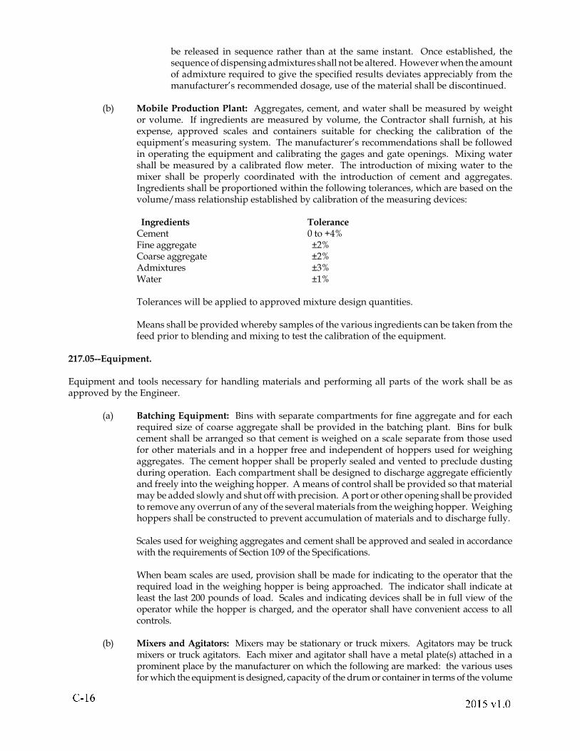
be released in sequence rather than at the same instant. Once established, the sequence of dispensing admixtures shall not be altered. However when the amount of admixture required to give the speci! ed results deviates appreciably from the manufacturer�s recommended dosage, use of the material shall be discontinued.
(b) Mobile Production Plant: Aggregates, cement, and water shall be measured by weight or volume. If ingredients are measured by volume, the Contractor shall furnish, at his expense, approved scales and containers suitable for checking the calibration of the equipment�s measuring system. The manufacturer�s recommendations shall be followed in operating the equipment and calibrating the gages and gate openings. Mixing water shall be measured by a calibrated " ow meter. The introduction of mixing water to the mixer shall be properly coordinated with the introduction of cement and aggregates. Ingredients shall be proportioned within the following tolerances, which are based on the volume/mass relationship established by calibration of the measuring devices:
Ingredients Tolerance Cement 0 to +4% Fine aggregate ±2% Coarse aggregate ±2% Admixtures ±3% Water ±1%
Tolerances will be applied to approved mixture design quantities.
Means shall be provided whereby samples of the various ingredients can be taken from the feed prior to blending and mixing to test the calibration of the equipment.
217.05--Equipment.
Equipment and tools necessary for handling materials and performing all parts of the work shall be as approved by the Engineer.
(a) Batching Equipment: Bins with separate compartments for ! ne aggregate and for each required size of coarse aggregate shall be provided in the batching plant. Bins for bulk cement shall be arranged so that cement is weighed on a scale separate from those used for other materials and in a hopper free and independent of hoppers used for weighing aggregates. The cement hopper shall be properly sealed and vented to preclude dusting during operation. Each compartment shall be designed to discharge aggregate ef! ciently and freely into the weighing hopper. A means of control shall be provided so that material may be added slowly and shut off with precision. A port or other opening shall be provided to remove any overrun of any of the several materials from the weighing hopper. Weighing hoppers shall be constructed to prevent accumulation of materials and to discharge fully.
Scales used for weighing aggregates and cement shall be approved and sealed in accordance with the requirements of Section 109 of the Speci! cations.
When beam scales are used, provision shall be made for indicating to the operator that the required load in the weighing hopper is being approached. The indicator shall indicate at least the last 200 pounds of load. Scales and indicating devices shall be in full view of the operator while the hopper is charged, and the operator shall have convenient access to all controls.
(b) Mixers and Agitators: Mixers may be stationary or truck mixers. Agitators may be truck mixers or truck agitators. Each mixer and agitator shall have a metal plate(s) attached in a prominent place by the manufacturer on which the following are marked: the various uses for which the equipment is designed, capacity of the drum or container in terms of the volume
! " #$ % " & ' " ( %
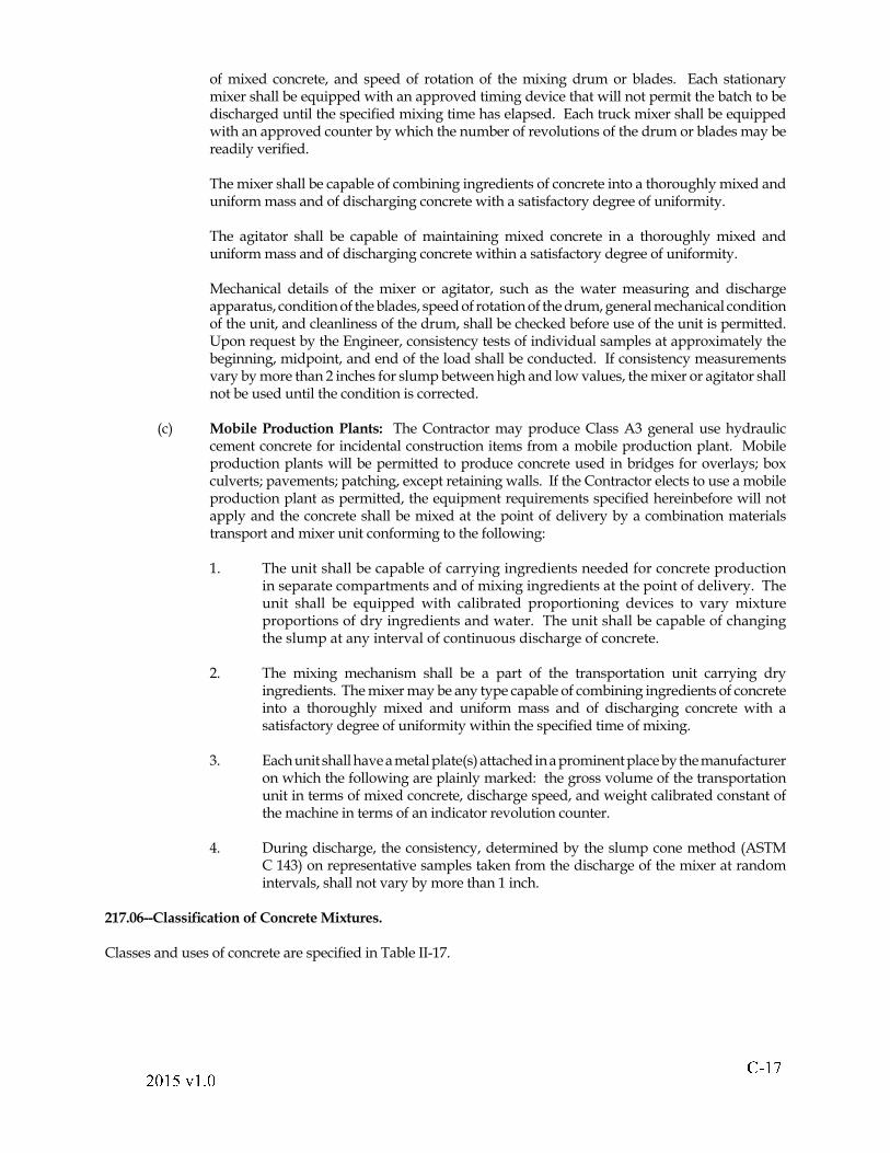
of mixed concrete, and speed of rotation of the mixing drum or blades. Each stationary mixer shall be equipped with an approved timing device that will not permit the batch to be discharged until the speci! ed mixing time has elapsed. Each truck mixer shall be equipped with an approved counter by which the number of revolutions of the drum or blades may be readily veri! ed.
The mixer shall be capable of combining ingredients of concrete into a thoroughly mixed and uniform mass and of discharging concrete with a satisfactory degree of uniformity.
The agitator shall be capable of maintaining mixed concrete in a thoroughly mixed and uniform mass and of discharging concrete within a satisfactory degree of uniformity.
Mechanical details of the mixer or agitator, such as the water measuring and discharge apparatus, condition of the blades, speed of rotation of the drum, general mechanical condition of the unit, and cleanliness of the drum, shall be checked before use of the unit is permitted. Upon request by the Engineer, consistency tests of individual samples at approximately the beginning, midpoint, and end of the load shall be conducted. If consistency measurements vary by more than 2 inches for slump between high and low values, the mixer or agitator shall not be used until the condition is corrected.
(c) Mobile Production Plants: The Contractor may produce Class A3 general use hydraulic cement concrete for incidental construction items from a mobile production plant. Mobile production plants will be permitted to produce concrete used in bridges for overlays; box culverts; pavements; patching, except retaining walls. If the Contractor elects to use a mobile production plant as permitted, the equipment requirements speci! ed hereinbefore will not apply and the concrete shall be mixed at the point of delivery by a combination materials transport and mixer unit conforming to the following:
1. The unit shall be capable of carrying ingredients needed for concrete production in separate compartments and of mixing ingredients at the point of delivery. The unit shall be equipped with calibrated proportioning devices to vary mixture proportions of dry ingredients and water. The unit shall be capable of changing the slump at any interval of continuous discharge of concrete.
2. The mixing mechanism shall be a part of the transportation unit carrying dry ingredients. The mixer may be any type capable of combining ingredients of concrete into a thoroughly mixed and uniform mass and of discharging concrete with a satisfactory degree of uniformity within the speci! ed time of mixing.
3. Each unit shall have a metal plate(s) attached in a prominent place by the manufacturer on which the following are plainly marked: the gross volume of the transportation unit in terms of mixed concrete, discharge speed, and weight calibrated constant of the machine in terms of an indicator revolution counter.
4. During discharge, the consistency, determined by the slump cone method (ASTM C 143) on representative samples taken from the discharge of the mixer at random intervals, shall not vary by more than 1 inch.
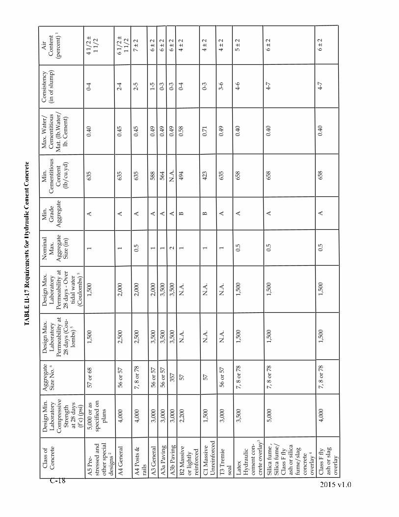
217.06--Classi! cation of Concrete Mixtures.
Classes and uses of concrete are speci! ed in Table II-17.
! " # $ % " & ' " ( %
)* + ,-.. /0 12 3 456 73839: ;< =7> ?@ 7A5B6 CD 3839:D =9C73: 3
Cla
ss o
f C
on
cret
eD
esig
n M
in.
Lab
ora
tory
C
om
pre
ssiv
e S
tren
gth
at
28 d
ays
(f�c
) (p
si)
Ag
gre
gat
e S
ize
No
. 6
Des
ign
Max
. L
abo
rato
ry
Per
mea
bil
ity
at
28 d
ays
(Co
u-
lom
bs)
5
Des
ign
Max
. L
abo
rato
ry
Per
mea
bil
ity
at
28 d
ays
- O
ver
ti
dal
wat
er
(Co
ulo
mb
s) 5
No
min
al
Max
. A
gg
reg
ate
Siz
e (i
n)
Min
. G
rad
e A
gg
reg
ate
Min
. C
emen
titi
ou
s C
on
ten
t (
lb/
cu.y
d)
Max
. Wat
er/
C
emen
titi
ou
s
Mat
. (lb
.Wat
er/
lb. C
emen
t)
Co
nsi
sten
cy(i
n o
f sl
um
p)
Air
C
on
ten
t (p
erce
nt)
1
A5
Pre
-st
ress
ed a
nd
o
ther
sp
ecia
l d
esig
ns
2
5,00
0 o
r as
sp
eci!
ed
on
p
lan
s
57 o
r 68
1,50
01,
500
1A
635
0.40
0-4
4 1/
2 ±
1
1/2
A4
Gen
eral
4,00
056
or
572,
500
2,00
01
A63
50.
452-
46
1/2
±1
1/2
A4
Po
sts
&
rail
s4,
000
7, 8
or
782,
500
2,00
00.
5A
635
0.45
2-5
7 ±
2
A3
Gen
eral
3,00
056
or
573,
500
2,00
01
A58
80.
491-
56
± 2
A3a
Pav
ing
3,00
056
or
573,
500
3,50
01
A56
40.
490-
36
± 2
A3b
Pav
ing
3,00
035
73,
500
3,50
02
AN
.A.
0.49
0-3
6 ±
2
B2
Mas
siv
e o
r li
gh
tly
re
info
rced
2,20
057
N.A
.N
.A.
1B
494
0.58
0-4
4 ±
2
C1
Mas
siv
e U
nre
info
rced
1,50
057
N.A
.N
.A.
1B
423
0.71
0-3
4 ±
2
T3
Tre
mie
se
al3,
000
56 o
r 57
N.A
.N
.A.
1A
635
0.49
3-6
4 ±
2
Lat
ex
Hy
dra
uli
c ce
men
t co
n-
cret
e o
ver
lay
3
3,50
07,
8 o
r 78
1,50
01,
500
0.5
A65
80.
404-
65
± 2
Sil
ica
fum
e ,
Sil
ica
fum
e/C
lass
F "
y
ash
or
sili
ca
fum
e/sl
ag
con
cret
e o
ver
lay
4
5,00
07,
8 o
r 78
1,50
01,
500
0.5
A65
80.
404-
76
± 2
Cla
ss F
" y
as
h o
r sl
ag
ov
erla
y
4,00
07,
8 o
r 78
1,50
01,
500
0.5
A65
80.
404-
76
± 2
! " #$ % " & ' " ( %) **+ ,*+ -. / 01 23415 61 784362 94: 2882; <=285 > <>2; ?:1 2: 4862: 45 8=@3: 23: >1 4AAB 25 3=824>2;CD 43; :1 2>A <EF>1 4AA 3@: 2 G=22;H5 3=1 2> I
J 01 2 3KA 4>>LM =@3=82: 25 > <>2; 4>:1 2N 35 >1 2;B 85; 62; 2=O 85;5 36> <8P 4=2 ?@8 91 235 :5 >: @B 2=@ Q282; 95 :1 4>F1 4A : =@3=82: 2 95 :1 @8 95 :1 @ <: 94: 28F8@@N 36 ?:1 245 8=@3: 23:
>1 4AAB 2MR SCRD I T U1 2A 4: 2 GE@;5N 28=@3: 23: >1 4AAB 2V IM 64AA @3>F28B 46@P =2E23: IWA <EF>1 4AAB 2E24> <82; 4FF8@ G5 E4: 2A XYR E5 3 <: 2>4P : 28;5 >=1 4862P 8@E:1 2E5 G28 I
Z W5A5 =4P <E2 95 :1 4E5 35 E <E@PHDB X925 61 : @P =2E23:5 :5 @ <>E4: 285 4A [>5A5 =4P <E2 95 :1 484362@P\ IM 7MD >1 4AAB 2=@EB5 32; 95 :1KA 4>>]]A XL >15 384362@PCM 7
\^D E5 35 E <E=2E23: @PHH IMDB X925 61 : @P =2E23:5 :5 @ <>E4: 285 4A [>5A5 =4P <E2 95 :1 484362@P\ IM 7MD >1 4AAB 2=@EB5 32; 95 :1_ 8@ <3;_ 843 <A 4: 2;`A 4>:] <834=2
WA 465 3:1 284362@PV^ 7VMD 43; 4E5 35 E <E=2E23: @PaH IMDB X925 61 : @P =2E23:5 :5 @ <>E4: 285 4A I
b U1 2F28E24B5A5 : X: 2>:5 36; @2>3@: 4FFA X: @>E4AAB 85; 62>5; 23:5N 2; @3:1 2B 85; 62FA 43>43; : @=@3=82: 2>: 8 <=: <82>43;5 3=5; 23: 4A =@3=82: 24>; 2>=85B 2;5 3W 2=:5 @3>
\Cc ?\V\ ?V^\ ?YCM ?M^\ ?M^Y ?M^a 43;MCc IK <85 3643; : 2>:5 36@P : 2>: = XA5A 3; 28>P @8F28E24B5A5 : X95AAB 25 34==@8; 43=2 95 :1dUe 7CC\ I
f U1 2=@3: 84=: @8E4 X<>2;5PP 2823: 4668264: 2>5 g2>@84=@EB5 34:5 @3@P >5 g2>: @5 3=824>2:1 2=@48>24668264: 2=@3: 23: @P :1 2=@3=82: 24>4FF8@ Q2;B X:1 2h 365 3228 IU1 2
E4 G5 E <E>5 g2@P :1 2=@48>24668264: 2>1 4AA 3@: 2 G=22;\ IM5 3=1 2> I
i jk lm05 :1 :1 24FF8@ Q4A @P :1 2h 365 3228 ?:1 2K @3: 84=: @8E4 X> <B >:5 : <: 2415 61 28=A 4>>@P =@3=82: 2P @8:1 4: >F2=5N 2; 4::1 2K @3: 84=: @8n >2 GF23>2 I
! " # " # $ % & $ ' #
217.07--Proportioning Concrete Mixtures.
The Contractor is responsible for having a Certi! ed Concrete Plant Technician available during batching operations, and a Certi! ed Concrete Field Technician shall be present during placing operations.
A Certi! ed Concrete Plant Technician is that person who is capable of performing adjustments in the proportioning of materials used to produce the speci! ed concrete should adjustments become necessary.
A Certi! ed Concrete Field Technician is that person who is responsible for quality control of concrete work at the project site. The Contractor shall have at least one Certi! ed Concrete Field Technician on the project for single or multiple incidental concrete placements. The Contractor shall have at least one Certi! ed Concrete Field Technician present at each site during the placement of pavements, bridge decks, bridge piers and abutments, box culverts and any placement of 50 or more cubic yards.
The Certi! ed Concrete Field Technician shall provide control over methods used for discharging, conveying, spreading, consolidating, screeding, ! nishing, texturing, curing and protecting the concrete. De! ciencies in conformance to speci! cation requirements and good concreting practices shall be corrected as soon as they begin to occur.
The concrete producer shall plan batching operations so that delays do not occur because of the absence of certi! ed personnel.
Concrete shall be proportioned to secure the strength and durability required for the pavement or the part of the structure in which it is to be used.
Prior to mixing concrete, the Contractor shall submit, or shall have his supplier submit, for approval concrete mixture design(s) conforming to the speci! cations for the class of concrete speci! ed.
The Contractor shall furnish and incorporate an approved water-reducing and retarding admixture in bridge deck concrete and in other concrete when conditions are such that the initial set may occur prior to completion of approved ! nishing operations. An approved water-reducing admixture shall be furnished and incorporated in concrete when necessary to provide the required slump without exceeding the maximum water/cement ratio and shall be used in bridge deck concrete when the requirement for a water-reducing and retarding admixture is waived by the Engineer. The Contractor shall demonstrate that use of the admixture will not cause segregation. The two admixtures shall not be used together in the same concrete batch unless tests indicate the admixtures are compatible in accordance with the requirements of Section 215.02 (b). Costs for admixture(s) shall be included in the contract unit price for the respective concrete item.
Concrete shall be air entrained. The air content shall conform to the requirements of Table II-17.
Except for latex hydraulic cement concrete, the quantities of ! ne and coarse aggregates necessary to conform to these speci! cations in regard to consistency and workability shall be determined by the method described in ACI 211.2 or ACI 211.1 except that proportions shall be computed on the absolute volume basis and the 10 percent adjustment allowed in Table 5.3.6 will not be permitted. The actual quantities used, as determined by the methods described herein, shall not deviate more than ±5 percent from such quantities.
For latex hydraulic cement content, the dry mass ratio of cement/! ne aggregate/coarse aggregate shall be 1:2.5:2. A maximum adjustment of 10 percent may be made in the masses of the aggregate, as approved by the Engineer, to compensate for grading changes and variable speci! c gravity.
Batch quantities shall be adjusted during the course of the work to compensate for changes in workability caused by differences in characteristics of aggregates and cements within the speci! cation requirements. Such adjustments shall be made only by the Contractor and shall not change the yield.
! " #" $ # % & # ' $
If concrete cannot be obtained with the required workability or consistency or with the maximum design water content with the materials furnished, the Contractor shall make changes to secure the desired properties subject to the limiting requirements speci! ed in Table II-17 and the approval of the Engineer. When the void content of the ! ne aggregate is more than 50.5 percent and the concrete does not have the desired properties, the Contractor shall use a ! ne aggregate having a void content of less than 50.5 percent. In lieu of changing the ! ne aggregate, the Contractor may take one or more of the following actions:
1. Use an approved water-reducing admixture.
2. Increase the cement content.
3. Change the source of coarse aggregate.
4. In hot weather, add ice or otherwise reduce the temperature to increase the workability.
5. Submit other recommendations to the Engineer for approval.
However, when any of the options is exercised, the Contractor shall make trial batches under the observation of the Engineer to verify that concrete of the required workability and consistency is obtained within the speci! ed water content. At least one trial batch shall be made with the concrete temperature at approximately 90 oF to verify that the concrete mixture has suf! cient workability and consistency without exceeding the speci! ed water content. When the ! neness modulus of the ! ne aggregate changes more than 0.2 from the original design and the concrete does not have the desired properties, the concrete mixture shall be redesigned. Costs incurred because of adjustments of concrete mixture design(s) and for trial batches shall be borne by the Contractor, and no additional compensation will be made.
217.08--Acceptance.
(a) Air and Consistency Tests: Air and consistency tests will be performed by the Department prior to discharge into forms to ensure that speci! cation requirements are consistently being complied with for each class of concrete. The sample secured for the tests shall be taken after at least 2 cubic feet of concrete has been discharged from the delivery vehicle. The two cubic feet discharged is not to be used as part of the test sample. Any deviation from sampling and testing procedures must be approved of the Engineer. The Contractor shall provide a receptacle conforming to the requirements of ASTM C31, Section 5.9, for the Department�s use in obtaining its sample. If either determination yields a result that is outside the allowable range for air content or consistency, the following procedures will be used:
1. The Engineer will immediately perform a recheck determination. If the results con! rm the original test results, the load will be rejected.
2. The Contractor�s representative will be immediately informed of the test results.
3. The Contractor�s representative shall notify the producer of the test results through a preestablished means of communication.
The Engineer may perform any additional tests deemed necessary and reject all remaining material that fails the tests.
Entrained air content will be determined in accordance with the requirements of ASTM C231 or C173. Acceptance or rejection will be based on the results obtained from these tests.
In general, a mixture that contains the minimum amount of water consistent with the required workability shall be used. Consistency will be determined in accordance with the
! " " " # $ % & $ ' #
requirements of ASTM C143. Adding cement to loads previously rejected for excessive water content or consistency will not be permitted.
(b) Strength Tests: The 28-day strengths speci! ed in Table II-17 are strengths used in the design calculations. The Engineer will verify design strengths by tests made during the progress of the work in accordance with the requirements of ASTM C39 and C31 with the exception that the fresh concrete sample used for testing is secured after at least two cubic feet has been discharged from the delivery vehicle. The two cubic feet discharged is not to be used as part of the test sample. Any deviation from sampling and testing procedures must be approved by the Engineer. If the test results do not conform to the strengths speci! ed in Table II-17, immediate steps shall be taken to adjust the design mixture and an investigation will be initiated by the Engineer to determine the acceptability of the concrete. Use of ASTM C42 will be at the Engineer�s discretion.
The Contractor shall provide a storage chamber at his expense for temporary storage of the Department�s concrete cylinders before concrete is placed. The contractor shall be responsible for the chamber maintaining the concrete test cylinders in a continuously moist condition within a temperature range of 60 oF to 80 oF and shall be equipped with a continuously recording thermometer accurate to ±2 oF for the duration of concrete ! eld cylinder curing period. The chamber shall be located in an area where the test cylinders will not be subject to vibration and shall be of suf! cient size or number to store, without crowding or wedging, the required number of test cylinders as determined by the Contractor based on his plan of operations. The chamber and location of the chamber must be approved by the Engineer.
When use of high-early-strength hydraulic cement concrete is required, it shall conform to the requirements of Table II-17 except that the 28-day strength shall be obtained in 7 days. Up to 800 pounds per cubic yard of Type I or Type II cement may be used to produce high-early-strength concrete in lieu of using Type III modi! ed cement.
(c) Concrete Temperature shall be measured in accordance with ASTM C1064.
217.09--Mixing.
The method of mixing shall be approved by the Engineer prior to the start of concrete work.
The volume of concrete mixed per batch shall be at least 15 but not more than 110 percent of the mixer�s rated capacity.
Concrete that becomes nonplastic, unworkable, or outside the limits of the slump speci! ed shall not be used. Retempered concrete shall not be used. Concrete delivery shall be regulated so that placement is at a continuous rate. Intervals between delivery of batches shall not be so great as to allow concrete in place to begin initial set.
(a) Mixing at Job Site: Concrete shall be mixed in a batch mixer designed to ensure a uniform distribution of materials throughout the mass. When bag cement is used, batches shall be proportioned on the basis of integral bags of cement.
Mixing shall be performed in accordance with the requirements of (b)3. herein.
Upon the cessation of mixing for more than 30 minutes, the mixer shall be thoroughly cleaned.
(b) Ready-Mixed Concrete: Ready-mixed concrete shall be delivered to the designated point ready for use.
! " #" $ % & ' % ( $
Each load of transit or shrink-mixed concrete shall be accompanied by Form TL-28 signed by the VDOT Certi! ed Concrete Plant Technician or a designated company representative working under the direction of the VDOT Certi! ed Concrete Plant Technician. The form shall be delivered to the Inspector at the site of the work. Loads that do not carry such information or that do not arrive in satisfactory condition shall not be used.
Each batch of concrete shall be delivered to the site of work and discharged within 90 minutes of the time the cement is introduced into the mixture unless otherwise approved by the Engineer.
Mixing and delivery shall be in accordance with the following:
1. Transit mixing: Concrete shall be mixed in a truck mixer. Mixing shall begin immediately after all ingredients are in the mixer and shall continue for at least 70 revolutions of the drum or blades at the rate of at least 14 but not more than 20 revolutions per minute.
Additional rotations of the drum or blades shall be at the rated agitating speed. The mixer shall be operated within the capacity and speed of rotation designed by the manufacturer.
2. Shrink mixing: Materials, including water, shall be partially mixed in a stationary mixer for at least 30 seconds. Mixing shall be completed in a truck mixer with at least 60 but not more than 100 revolutions of the drum or blades at the rated mixing speed. Additional rotations of the drum or blades shall be at the rated agitating speed. Mixers shall be operated within the capacity and speed of rotation designated by the manufacturer of the equipment.
3. Central mixing: Concrete shall be completely mixed in a stationary mixer and transported in the agitator equipment to the point of delivery. Use of nonagitator equipment will be approved only when the plant is in the immediate vicinity of the project.
Mixing time for mixers having a capacity of 1 cubic yard or less shall be at least 60 seconds. Mixing time for mixers having a capacity of more than 1 but less than 10 cubic yards shall be at least 75 seconds. Mixing times for mixers having a capacity of more than 10 cubic yards shall be as determined by the Engineer. Performance tests shall be conducted in accordance with the requirements of VTM-17 by an approved commercial laboratory at the Contractor�s expense. Lesser times will be approved if the requirements of VTM-17 are conformed to. In any event, mixing time shall be not less than 40 seconds.
The requirements of VTM-17 shall not be construed as a nulli! cation of the requirements of Table II-17. If subsequent evaluation check tests indicate that the reduced mixing time is not satisfactory, the Contractor shall reestablish the necessary mixing time.
Concrete mixed for less than the speci! ed time will be rejected. Mixing time starts when solid materials are in the mixing compartment and ends when any part of the concrete begins to discharge. The mixer shall be operated at the drum speed speci! ed on the name plate of the approved mixer.
Bodies of nonagitating equipment used to transport concrete shall be smooth, mortartight, non-aluminum metal containers capable of discharging concrete at a
! " # " $ % & ' % ( $
controlled rate without segregation. Upon discharge of concrete, the body of the equipment shall be free from concrete. Concrete shall be delivered to the work site in a thoroughly mixed and uniform mass. Upon the request of the Engineer, consistency tests of individual samples at approximately the beginning, midpoint, and end of the load shall be conducted. If consistency measurements vary by more than 2 inches for slump between high and low values, mixer or agitator equipment shall be used in lieu of nonagitating equipment.
(c) Automatic Mobile Continuous Mixers: Mobile continuous mixers shall be calibrated to proportion the mixture accurately and shall have been certi! ed within 60 days prior to use on the project for the type of material speci! ed. Certi! cations will be valid for 6 months or until the source of materials changes or the grading or moisture changes signi! cantly so as to affect the consistency of the concrete. Evaluation and certi! cation will be performed by the Department or an approved testing agency to determine that the true yield is within a tolerance of ±1.0 percent. A recording meter, visible at all times and equipped with a ticket printout, shall indicate the calibrated measurement.
(d) Hand Mixing: Hand mixing will be permitted only in case of emergency and with permission. Batches shall be not more than ½ cubic yard and shall be mixed in a watertight container in a manner approved by the Engineer. Ingredients shall be measured by placing them in any suitable, rigid container in the volumetric proportions of 1 part cement to 2 parts ! ne aggregate to 2 1/2 parts coarse aggregate. The container shall be ! lled and leveled with each ingredient to ensure the proportions speci! ed as nearly as possible. Water shall be added to produce a slump of not more than 3 inches.
217.10--Placement Limitations.
The Contractor shall be responsible for the quality of concrete placed in any weather or atmospheric condition. At the time of placement, concrete shall have a temperature in accordance with the following:
(a) Class A3 general use concrete used in the construction of incidental items speci! ed in Division V of these speci! cations, except retaining walls, shall have a temperature of at least 40 oF but not more than 95 oF.
(b) Class A3 paving concrete placed by the slipform method and containing an approved water reducer shall have a temperature of at least 40 oF but not more than 95 oF.
(c) Concrete used in the construction of bridge decks shall have a temperature of at least 40 oF but not more than 85 oF.
(d) Retaining walls and other concrete not speci! ed in 1., 2., or 3. herein shall have a temperature of at least 40 oF but not more than 90 oF.
In cold weather, water and aggregates may be heated to not more than 150 oF to maintain concrete at the required temperature. The heating apparatus shall be such that materials will be heated uniformly and the possibility of the occurrence of overheated areas that might damage materials will be precluded. Steam shall not come in contact with aggregates. Cement shall not be heated. Heating equipment or methods that alter or prevent entrainment of the required amount of air in concrete shall not be used. Materials containing frost, lumps, crusts, or hardened material shall not be used.
In hot weather, aggregates or the mixing water shall be cooled as necessary to maintain the temperature of the concrete within the speci! ed maximum.
! " #" ! # " ! #
SECTION 220--CONCRETE CURING MATERIALS
220.01--Description.
These speci! cations cover materials used to maintain the humidity and temperature of freshly placed concrete to ensure satisfactory hydration and proper hardening of the concrete.
220.02--Detail Requirements.
Concrete curing materials shall consist of waterproof paper, PE ! lm, a combination of burlap and PE ! lm, liquid membrane-forming compound, or water. Concrete curing materials shall be free from impurities that may be detrimental to the surface of concrete.
(a) Waterproof paper shall conform to the requirements of AASHTO M171. One side shall be composed of white, light-re" ecting paper.
(b) PE ! lm shall conform to the requirements of AASHTO M171 except that its nominal thickness shall be 3.0 mils. The thickness at any point shall be at least 2.5 mils.
(c) Burlap and PE ! lm may be used in combination. They shall be bonded securely so that they cannot be easily separated in a dry or saturated condition. White PE ! lm shall conform to the re" ectance requirements of AASHTO M171. Burlap shall conform to the requirements of AASHTO M182, Class 3.
(d) Liquid membrane-forming compounds shall be used on concrete masonry except bridge substructure elements. Fugitive dye compounds shall be used on bridge substructure elements. The Contractor shall remove liquid membrane-forming compound from concrete surfaces to which a bonding compound, joint sealer, or waterproo! ng material is to be applied.
Liquid membrane-forming compounds will be tested in accordance with the requirements of VTM-2 and shall conform to the following:
1. Liquid membrane-forming compounds shall contain an easily dispersed opaque, white, ! nely ground pigment or a fugitive dye. They shall not react with the components of concrete and shall not contain oils, waxes, or other materials that would prevent bonding of traf! c paints. The resulting ! lm shall be continuous, uniform, and free from pinholes, bubbles, or blisters and shall not darken the hardened concrete. The dye shall have suf! cient color to be distinctly visible for at least 30 minutes after application and to disappear within 7 days.
2. The membrane shall not peel. It shall disappear by gradual disintegration from exposure to the elements over a period of at least 30 days but not more than 1 year. Within 60 days after application, the membrane shall be capable of being readily removed by means of steel wire brushes or another abrasive that will not damage the concrete surface.
3. When applied by pressure spray to a troweled, vertical, damp concrete surface at the rate speci! ed, material shall adhere to the surface in a continuous, tenacious ! lm without running off or sagging appreciably.
4. Shipping containers shall identify the trade name of the material and a lot or batch number except for small, locally repackaged containers bearing the Department�s seal.
! " # " $ % & ' % ( $
5. The average moisture loss at 24 hours shall be not more than 0.20 kilograms per square meter of exposed surface. At 72 hours, it shall be not more than 0.30 kilograms per square meter.
6. When applied to the test specimen, white pigmented material shall have a daylight re" ectance of at least 60 percent of that of magnesium oxide.
(e) Water used for curing concrete shall be clean, clear, and free from oil and other deleterious substances and shall have a pH of at least 4.5.
SECTION 223--STEEL REINFORCEMENT
223.01--Description.
These speci! cations cover steel items designed to give added " exural strength to hydraulic cement concrete or to control and reduce cracking.
223.02--Detail Requirements.
(a) Reinforcement:
1. Deformed bars shall conform to the requirements of ASTM A615, Grade 40 or 60.
2. Plain bars shall conform to the requirements of ASTM A615, Grade 40 or 60, deformation waived. When used as a dowel, material may be a plain bar, Grade 40 or 60 (ASTM A615), or a plain dowel (ASTM A709 Grade 36).
3. Welded wire fabric shall conform to the requirements of ASTM A185. When used in continuously reinforced pavement, wire fabric shall be deformed and furnished in " at sheets and shall conform to the requirements of ASTM A497 (high yield of 70,000 pounds per square inch).
4. Longitudinal bars for continuous reinforced concrete pavement shall conform to the requirements of ASTM A615, Grade 60.
5. Structural steel shall conform to the requirements of Section 226.
6. Bar mats shall conform to the requirements of ASTM A184.
7. Spiral wire shall conform to the requirements of AASHTO M32 (ASTM A82).
8. Wire mesh for use in gabions shall be made of galvanized steel wire at least 0.105 inches (12 gage) in diameter. The tensile strength of the wire shall be at least 60,000 pounds per square inch. Wire mesh shall be galvanized in accordance with the requirements of ASTM A641, Class 3. When PVC coating is speci! ed, it shall be at least 0.015 inches in thickness and shall be black.
Wire shall be welded to form rectangular openings or twisted to form hexagonal openings of uniform size. The linear dimension of the openings shall be not more than 4 ½ inches. The area of the opening shall be not more than 9 square inches. The unit shall be nonraveling. Nonraveling is de! ned as the ability to resist pulling apart at any of the twists or connections forming the mesh when a single wire strand in a section is cut.
! " #" $ % & ' % ( $
(b) Prestressing Tendons: Seven-wire stress-relieved strands, stress-relieved wire, and low-relaxation strands shall conform to the requirements of ASTM A416, Grade 270; ASTM A421; and ASTM A416, Supplement I; respectively, with the following modi! cations:
1. Strands or wires used in units of any one bed layout shall be manufactured by the same plant.
2. A manufacturer�s certi! cation and load-elongation curve, in accordance with the requirements of ASTM A416 or A421, shall be obtained by the prestressed concrete fabricator for each lot of strand. The data shall be submitted to the Engineer for approval, in permanent record form.
(c) Reinforcing Steel To Be Epoxy Coated: Steel shall conform to the requirements herein and shall be coated in accordance with the requirements of AASHTO M284.
1. Plants that epoxy coat reinforcing steel shall be CRSI certi! ed for epoxy coating. CRSI inspection reports shall be on ! le at the plant and shall be available to the Engineer.
2. Handling and storage of the coated bars shall conform to the requirements of AASHTO M284.
3. Visible damage to the epoxy coating shall be patched or repaired with materials compatible to the existing coating in accordance with AASHTO M284.
(d) Reinforcing Steel To Be Galvanized: Steel shall conform to the requirements herein and shall be galvanized in accordance with requirements of ASTM A767.
SECTION 241--FLY ASH
241.01--Description.
These speci! cations cover " y ash (burnt coal residue) used as an additive in hydraulic cement concrete or as a soil stabilizer.
241.02--Detail Requirements.
(a) Fly ash or natural pozzolans used in hydraulic cement concrete shall conform to the requirements of ASTM C618, Class F, Class C, or Class N.
(b) Fly ash used in lime stabilization shall conform to the requirements of ASTM C593. Bulk material may be used as approved by the Engineer.

! " # " $ % & ' % ( $
Division III
Roadway Construction
! " #" $ % & ' % ( $
SECTION 316--HYDRAULIC CEMENT CONCRETE PAVEMENT
316.01--Description.
This work shall consist of constructing pavement and approach slabs composed of hydraulic cement concrete, with or without reinforcement as speci! ed, or a continuously reinforced pavement on a prepared subgrade or base course in accordance with the requirements of these speci! cations and in reasonably close conformity with the lines, grades, thicknesses, and typical cross sections shown on the plans or as established by the Engineer.
316.02--Materials.
(a) Concrete shall be central mixed and shall conform to the requirements of Table II-17 for Class A3 paving concrete except that the slump shall be not more than 2 inches for placement by the slipform method. Concrete for placement by the slipform method shall be suf! ciently cohesive to prevent detrimental sloughing at the pavement edges as the forms advance. Transit mixture concrete may be furnished for use in constructing approach slabs, ramps, transitions, connections, crossovers, and other miscellaneous pavement. Aggregate used in concrete for pavement and approach slabs that are used as riding surfaces shall be nonpolishing aggregate.
(b) Reinforcing steel dowels, tie bars, hook bolts, and welded wire fabric shall conform to the requirements of Section 223.
(c) Wide " ange beams used in the anchor slab of continuously reinforced pavement shall conform to the requirements of ASTM A36.
(d) Joint sealer and ! ller shall conform to the requirements of Section 212.
(e) Load transfer devices shall be fabricated of steel and shall be of an approved type and design.
(f) Curing materials shall conform to the requirements of Section 220.
316.03--Equipment.
Equipment and tools necessary for handling materials and performing the work shall be subject to the approval of the Engineer.
The Contractor shall provide the equipment and tools speci! ed herein, or their approved equivalent, and they shall be of such capacity that the rate of placing concrete and ! nishing pavement will be continuous. If any piece of equipment does not have suf! cient capacity to keep pace with the other operations, the Contractor shall limit the size of the batch or otherwise limit the rate of production to preclude poor workmanship or frequent delays.
(a) Forms: Straight side forms shall be made of metal at least 7/32 inch in thickness and shall be furnished in sections at least 10 feet in length. Forms shall have a depth at least equal to the prescribed edge thickness of the concrete, without horizontal joints, and a base width equal to at least the depth of the forms. Flexible or curved forms of proper radius shall be used for curves with a radius of 100 feet or less. Flexible or curved forms shall be of a design acceptable to the Engineer. Forms shall be provided with adequate devices for secure placement so that when set they will withstand the impact and vibration of consolidating and ! nishing without visible springing or settlement. Flange braces shall extend outward on the base at least 2/3 the height of the form. Forms that are bent, twisted, or broken or that have battered top surfaces shall be removed. Repaired forms shall not be used until
! " # $ # % & ' % ( #
inspected and approved. Built-in forms shall not be used except where the total area of pavement on the project is less than 2,000 square yards. The top face of the form shall not vary from a true plane more than 1/8 inch in 10 feet, and the vertical side shall not vary from a true plane more than ¼ inch in 10 feet. Forms shall contain provisions for locking the ends of abutting form sections together tightly and for secure setting.
(b) Subgrade Machine: The machine shall be of an approved mechanical type, capable of preparing the subgrade to within ¼ inch of the grade shown on the plans or established by the Engineer.
(c) Subgrade Roller: The roller shall be of an approved type and capable of obtaining the required density.
(d) Bulkheads: Bulkheads for construction joints shall be of suf! cient strength to prevent deformation of the joint and shall be constructed to permit dowels or other reinforcement to extend through the joint.
(e) Work Bridges: Work bridges shall be provided by the Contractor.
(f) Mechanical Spreader: The mechanical spreader shall be a self-powered, self-propelled unit capable of placing the concrete mechanically on the subgrade over the full width and depth of the pavement.
The spreader shall be equipped with a hopper or other type of spreading equipment that will distribute the concrete over the subgrade without segregation. The concrete shall not be placed directly on the subgrade from the hauling equipment except in areas where hand labor must be performed.
(g) Vibrators: Vibrators for full-width vibration of concrete pavements shall be internal vibrators with multiple spuds. They may be attached to the spreader or mounted on a separate carriage operating directly behind the spreader. The frequency of vibrators shall be at least 7,000 impulses per minute.
When spud internal vibrators, either hand operated or attached to spreaders, are used adjacent to forms, they shall have a frequency of at least 3,500 impulses per minute.
Vibration shall be controlled by the forward movement of the spreader so that vibration automatically ceases when the forward movement of the spreader is stopped.
(h) Spraying Equipment: When liquid membrane-forming compound is used for curing concrete pavement, the Contractor shall provide mechanical spraying equipment mounted on movable bridges. The equipment shall be the full atomizing type equipped with a tank agitator and a gage to measure the quantity of material applied. The equipment shall be capable of continuously agitating the membrane during application.
(i) Concrete Saw: When sawing joints is elected or speci! ed, the Contractor shall provide sawing equipment adequate in number of units and power to complete the sawing to the required dimensions and at the required rate with a water-cooled, diamond-edged saw blade or an abrasive wheel.
(j) Slipform Paver: The paver shall be designed to consolidate, screed, and " oat ! nish the freshly placed concrete in one complete pass of the machine and in a manner so that a minimum of hand ! nishing will be necessary to provide a dense and homogeneous pavement. The paver shall be equipped to vibrate the concrete thoroughly for the full width and depth of the strip of pavement being placed.
! " #$ % # & ' # ( %
316.04--Procedures.
(a) Concrete Base Course: The subgrade or subbase upon which the base course is to be placed shall be prepared in accordance with the requirements of the applicable provisions of these speci! cations for such course.
The construction of a hydraulic cement concrete base course shall conform to the requirements of these speci! cations except for " oating and ! nal ! nishing of the surface. The surface shall be ! nished so that there will be no deviation of more than ¼ inch between any two contact points when tested with a 10-foot straightedge placed parallel to the center line. A heavy broomed texture shall be applied.
(b) Preparing Grade: The subgrade shall be prepared as speci! ed in Section 305. The course upon which the concrete pavement will rest, including the area that will support the paving equipment, shall be graded and compacted to the required pro! le.
Before or after side forms have been securely set to grade, the subgrade or subbase course shall be brought to the proper cross section. The ! nished grade shall be maintained in a smooth and compacted condition until pavement is placed.
The subgrade or subbase course shall be uniformly moist when concrete is placed. However, the method of moistening shall not be such as to form mud or pools of water.
(c) Placing Reinforcing Steel for Continuously Reinforced Pavement: At each location where ! ve or more consecutive days will elapse between placement operations, a �leave out� joint shall be installed as detailed on the plans. Longitudinal bars shall be positioned in the ! nished pavement within ±1/2 inch of the speci! ed vertical position and ±1 inch of the speci! ed horizontal position with a cover of at least 2 inches.
Prebent deformed tie bars, Grade 40 or 60, may be used in the joint between the mainline and ramp pavement to facilitate the use of the slipform paver. Bars shall be prebent with equipment designed especially for fabricating 90-degree bends in 5/8 inch deformed bars without damage to the bars. Side forms of the slipform paver shall be designed in a manner so that the prebent tie bars can be inserted in an appropriate slot and will pass between the edge of the pavement and the inside face of the trailing forms as the paver advances.
When reinforced concrete pavement is placed in two layers, the entire width of the bottom layer shall be vibrated and struck off to such length and depth that the sheet of fabric or bar mat may be laid full length on the concrete in its ! nal position without further manipulation. The reinforcement shall then be placed directly on the concrete, after which the top layer of concrete shall be placed, struck off, and screeded. Any portion of the bottom layer of concrete that has been placed more than 30 minutes without being covered with the top layer shall be removed and replaced with freshly mixed concrete at the Contractor�s expense. When reinforced concrete is placed in one layer, the reinforcement may be positioned in advance of concrete placement or placed by approved mechanical or vibratory means in fresh concrete after spreading.
Reinforcing steel shall be straight, and its surface condition shall conform to the requirements of Section 406.03(b).
(d) Setting Forms: The foundation under forms shall be compacted to grade so that forms, when set, will be ! rmly in contact for their entire length and at the speci! ed grade. Any foundation grade that is found to be low shall be ! lled to grade with granular material in lifts of ½ inch or less for a distance of 18 inches on each side of the base of the form and thoroughly compacted. Imperfections or variations above grade shall be corrected by tamping or cutting as necessary.
! " # # $ % & ' % ( $
Forms shall be set at least 500 feet in advance of concrete placement. Where local conditions make this requirement impracticable, it may be waived. After the forms have been set, the grade shall be thoroughly tamped at the inside and outside edges of the base of forms. Forms shall be staked into place with a suf! cient number of pins of suf! cient length for any section to hold the form at the correct line and grade. Form sections shall be tightly locked, free from play or movement. The top of the form, when tested with a 10 foot straightedge, shall not deviate more than 1/8 inch and the longitudinal axis of the vertical face shall not vary more than ¼ inch from the straightedge. No excessive settlement or springing of forms under the ! nishing machine will be allowed. Forms shall be cleaned and oiled prior to concrete placement.
The alignment and grade elevation of forms shall be checked and corrections made by the Contractor immediately before concrete placement. If any form has been disturbed or any grade has become unstable, the form shall be reset and rechecked.
(e) Placing Concrete: Concrete shall be placed on the grade in a quantity that will provide a uniform and adequate supply for the ! nishing equipment. Spreading shall be accomplished with a mechanical spreader. Necessary hand spreading shall be performed using square-faced shovels. The use of rakes or hoes will not be permitted. Workers shall not be allowed to walk in the freshly mixed concrete with boots or shoes coated with soil or foreign substances.
Where concrete is placed adjoining a previously constructed lane and mechanical equipment will be operated from the existing lane, the concrete in that lane shall have attained a modulus of rupture strength of at least 450 pounds per square inch. Test specimens for this purpose shall conform to the requirements of ASTM C 31 and shall be tested in accordance with the requirements of ASTM C 293. Equipment that will damage the surface of the existing pavement will not be permitted.
Concrete shall be thoroughly consolidated against forms and joint assemblies by means of full-width vibration. Vibrators will not be permitted to come in contact with a joint assembly, reinforcement, or side forms. The vibrator shall not be operated for more than 15 seconds in any one location. When fabric or bar mat reinforcement is placed by mechanical equipment that uses vibration or a tamping action, other vibratory equipment may be eliminated except in areas adjacent to side forms.
Concrete shall be placed as close to expansion and contraction joints as is possible without disturbing the joints. Concrete shall be placed over and around dowels in a manner so that dowels are fully embedded without displacement.
Concrete for continuously reinforced pavement shall be placed through the openings in the steel in one lift and vibrated with an internal vibrator for the entire width and depth. Special attention shall be given to the consolidation of the concrete in the immediate vicinity of construction joints and other areas where the performance of vibrators mounted on the paving equipment is questionable.
Following concrete placement, concrete shall be struck off to conform to the cross section shown on the plans and to an elevation such that when the concrete is properly consolidated and ! nished, the surface of the pavement will be reasonably close to the elevation shown on the plans or as established by the Engineer.
If concrete operations are permitted to extend after sunset, adequate lighting shall be provided.
(f) Test Specimens: The Contractor shall furnish the concrete necessary for casting test beams in accordance with the requirements of Section 316.04 (o). Beams shall be cured by a designated method as speci! ed for the pavement in accordance with the requirements of ASTM C 31.
! " "# $ % & ' % ( $
(g) Jointed Pavement: Joints shall be installed in a manner and at such time to prevent random or uncontrolled cracking. If random or uncontrolled cracking occurs, suf! cient concrete shall be removed and replaced on each side of the cracking to form a slab at least 10 feet long. Transverse construction joints shall be constructed at each end of the slab in accordance with the requirements of applicable provisions of 4. herein.
1. Longitudinal joints: Deformed tie bars of the speci! ed length, size, spacing, and material shall be placed perpendicular to the longitudinal joints. They shall be placed by approved mechanical equipment and rigidly secured by chairs or other approved supports to prevent displacement or by the insertion of bars with an approved hand tool. When adjacent lanes of pavement are constructed separately, approved two-piece connectors shall be used.
Longitudinal joints shall be sawed, formed, or created using a strip insert. Longitudinal center joints shall be installed in a manner so that full contact is made at intersections with transverse joints.
a. Formed joints: Formed joints shall consist of a groove extending downward from, and normal to, the surface of the pavement and shall be formed by an approved nonmetallic or removable device that consistently demonstrates its ability to produce in fresh concrete a joint having the dimensions and line indicated on the plans. The groove shall be sealed with a premolded or poured joint material as required.
b. Strip insert joints: A longitudinal weakened plane joint may be furnished at traf! c lane lines in multilane monolithic concrete pavement in lieu of forming or sawing such joints. Strip insert joints shall be formed by placing a continuous strip of plastic or other approved material. The insert strip shall be of suf! cient width to form a weakened plane to the depth shown on the plans. The thickness of the insert material shall be at least 20 mils. Strip insert joints shall not be sawed.
The insert strip shall be inserted with a mechanical device that places the material in a continuous strip. Splices will be permitted provided they are effective in maintaining the continuity of the insert strip. The top edge of the insert strip shall be positioned " ush with the ! nished surface. The insert strip shall not be deformed from a vertical position during installation or in subsequent ! nishing operations performed on the concrete. The alignment of the ! nished joint shall be uniformly parallel with the center line of the pavement and free from local irregularities in alignment that are more than ½ inch in 10 feet. The mechanical installation device shall vibrate the concrete during the insertion of the strip in a manner to cause the disturbed concrete to return evenly along the sides of the strip without segregating or developing voids.
If the Contractor is unable to furnish a satisfactory strip insert joint consistently, he shall, upon being noti! ed by the Engineer, discontinue furnishing such joints and furnish other approved formed or sawed joints without additional compensation.
c. Sawed joints: Longitudinal sawed joints shall be cut by approved concrete saws. Suitable guidelines or devices shall be used to ensure cutting the longitudinal joint on the true line as shown as soon as the concrete has hardened suf! ciently to permit sawing without chipping, spalling, or tearing. Concrete faces of the saw cut shall be protected from drying until the end of the speci! ed curing period. Sawed joints shall be thoroughly cleaned and dried prior to being sealed.

! " # $ % & ' ( & ) %
2. Transverse expansion joints: Transverse expansion joints shall be formed in accordance with the requirements of 1.a. herein and shall be sealed using Type D material. Expansion joint ! ller shall be continuous from form to form, shaped to the subgrade. Preformed joint ! ller shall be furnished in lengths equal to the pavement width or the width of one lane. Damaged or repaired joint ! ller shall not be used.
Expansion joint ! ller shall be held in a position perpendicular to the subgrade. An approved installing bar, or other device, shall be used, if required, to secure preformed joint ! ller at the proper grade and alignment during placing and ! nishing of concrete. Finished joints shall not deviate more than ¼ inch in the horizontal alignment from a straight line. If joint ! ller is assembled in sections, there shall be no offsets between adjacent units.
3. Transverse contraction joints: Transverse contraction joints shall consist of planes of weakness created by cutting grooves in the surface of the pavement and, when shown on the plans, shall include load transfer assemblies.
Edges of concrete adjacent to the joint may be rounded or beveled to a radius or length approved by the Engineer. Any joint having insuf! cient opening shall be resawed or ground to the proper size. Where a joint opening is larger than that speci! ed, the Contractor may be required to build up the joint with epoxy mortar or to furnish a larger size seal as determined by the Engineer. The cost of any such additional work or material shall be borne by the Contractor.
4. Transverse construction joints:
a. Jointed pavement: Unless speci! ed expansion joints occur at the same points, transverse construction joints shall be constructed at the end of each day�s work or when there is an interruption of more than 30 minutes in the concreting operations. A transverse construction joint shall not be constructed within 10 feet of an expansion joint, contraction joint, or plane of weakness. If suf! cient concrete has not been mixed at the time of interruption to form a slab at least 10 feet long, the excess concrete back to the last preceding joint shall be removed and disposed of as directed. An approved header board, cut to the required cross section, shall be used to form joints. Deformed dowel bars shall be used in transverse construction joints whose location does not coincide with the speci! ed location of a transverse expansion or contraction joint.
b. Continuously reinforced concrete pavement: Transverse construction joints shall be formed by the use of an approved header board in accordance with the requirements of 4.a. herein. The header shall consist of two sections, one being placed above and one being placed below the reinforcing mat, and shall be furnished with openings to accommodate the longitudinal steel and additional reinforcement required.
At any location where a �leave out� is necessary for a detour, at least 100 feet shall be maintained between transverse construction joints.
5. Load transfer devices: Plain dowels shall be held in position parallel to the surface and center line of the slab by a metal device that is left in the pavement.
! " #$ % & # ' & ( %
The entire free end of each dowel shall be painted with one coat of approved paint. When the paint has dried and immediately before dowels are placed in position, the free end shall be thoroughly coated with an approved lubricant. A metal or plastic dowel cap of approved design to cover 2 inches, ±1/4 inch, of the dowel, with a closed end, and with a suitable stop to hold the end of the sleeve at least 1 inch from the end of the dowel bar shall be furnished for each dowel bar used in expansion joints. Caps or sleeves shall ! t the dowel bar tightly, and the closed end shall be mortartight. Dowels, plastic coated in accordance with the requirements of Federal Speci! cation L-C-530 C or epoxy coated in accordance with the requirements of ASTM A775, may be used in lieu of painted and lubricated dowel bars.
In lieu of using dowel assemblies at contraction joints, dowel bars may be placed in the full thickness of pavement by an approved device.
6. Isolation joints at structures: Isolation joints shall be formed by placing a strip of ½ inch preformed expansion joint ! ller around each structure that extends into or through the pavement before concrete is placed at that location.
(h) Final Striking Off, Consolidating, and Finishing: The sequence of operations shall be as follows: (1) striking off, (2) consolidating, (3) " oating, (4) removing laitance, (5) straightedging, and (6) ! nishing. If the application of moisture to the surface is permitted, it shall be applied as a fog spray by means of approved spray equipment.
1. Finishing at joints: Concrete adjacent to joints shall be mechanically vibrated to prevent voids and segregation from occurring against the joint material, also under and around load transfer devices, joint assembly units, and other features designed to extend into the pavement.
a. Machine ! nishing: Concrete shall be spread as soon as placed, struck off, and then screeded by an approved ! nishing machine. Vibration for the full width of the paving slabs shall be provided in accordance with the requirements of Section 316.03(g). The machine shall be operated over each area of pavement as many times and at such intervals as necessary to result in proper consolidation and develop a surface of uniform texture. Excessive manipulation of a given area shall be avoided.
During the ! rst pass of the ! nishing machine, a uniform roll of concrete shall be maintained ahead of the front screed for its entire length.
If a uniform and satisfactory density of concrete is not obtained at joints, along forms, at structures, and throughout the pavement, the Contractor will be required to furnish equipment and use methods that will produce pavement conforming to the requirements speci! ed herein.
b. Hand ! nishing: Hand ! nishing will be permitted only under the following conditions: (1) to ! nish concrete already deposited on the grade in the event of a breakdown of mechanical equipment; and (2) to ! nish narrow widths, approach slabs, or other areas of irregular dimensions where the operation of mechanical equipment is impractical.
Concrete shall be struck off as it is placed and screeded with an approved portable screed. If reinforcement is required, the bottom of concrete shall be screeded prior to placement of reinforcement.
Consolidation shall be attained by the use of an approved vibrator or other approved equipment.
! " # $ % & ' ( & ) %
Hand ! nishing shall be kept to the absolute minimum necessary to attain a surface that has a uniform texture, is true to the approximate grade and cross section, and has a closed surface.
2. Floating: After concrete has been struck off and consolidated, it shall be further smoothed and made true by means of a " oat using one of the following methods as speci! ed or permitted:
a. Mechanical method: A mechanical " oat shall be adjusted so that its full length will be in continuous contact with the surface of the pavement.
If necessary, long-handled " oats having blades at least 5 feet in length and 6 inches in width may be used to smooth and ! ll in open-textured areas in the pavement. Long-handled " oats shall not be used to " oat the entire surface of the pavement in lieu of, or supplementing, the prescribed method of " oating.
b. Hand method: This method will be permitted only in those instances speci! ed in 1.b. herein. Following strike off by an approved screed, concrete shall be smoothed with a darby to level raised spots or ! ll depressions. Long-handled " oats or hand " oats of wood or metal, as the area dictates, may be used in lieu of darbies to smooth and level the concrete surface. Excessive bleed water shall be wasted over the side forms after each pass of the " oat.
3. Straightedge testing and surface correction: After " oating has been completed and excess water removed, but while concrete is still fresh, the surface of the concrete shall be tested for trueness with a 10 foot straightedge. The Contractor shall furnish and use an accurate 10 foot straightedge swung from handles 3 feet longer than 1/2 the width of the slab. The straightedge shall be held in contact with the surface in successive positions parallel to the pavement center line, and the entire area shall be gone over from one side of the slab to the other as necessary. Advancement along the pavement shall be in successive stages of not more than 1/2 the length of the straightedge. Depressions shall be immediately ! lled with freshly mixed concrete, stuck off, consolidated, re! nished, and retested. High areas shall be cut down and re! nished. Special attention shall be given to ensure that the surface across joints conforms to the requirements for smoothness. Straightedge testing and surface corrections shall continue until the entire surface is found to be free from observable departures from the straightedge and the slab conforms to the required grade and cross section.
4. Final ! nish (texture): Prior to grooving, multi-ply damp fabric shall be dragged over the pavement surface to provide a gritty texture on ridges between grooves. The roadway pavement riding surface shall be textured with (1) uniformly pronounced grooves approximately 1/8 inch in depth and 1/8 inch in width on approximately ¾ inch centers and transverse to the pavement center line, or (2) a combination of uniformly pronounced grooves approximately 1/8 inch in depth and 1/8 inch in width on approximately 3/4 inch centers and longitudinal to the pavement center line, and additional grooves 1/8 inch in depth and 1/8 inch in width on approximately 3 inch centers and transverse to the pavement center line.
(i) Stenciling Station Numbers and Dates: Before concrete takes its ! nal set and after ! nishing operations are completed, the Contractor shall stencil station numbers and dates into the pavement in accordance with the standard drawings. The dies for numbering and dating will be furnished by and remain the property of the Department. Dies or numerals lost or damaged by the Contractor shall be replaced at his expense.
! " #$ % & ' ( & ) %
(j) Curing:
1. Membrane-forming compounds: The entire surface of the pavement shall be sprayed uniformly with a white pigmented membrane-forming compound immediately following the texturing operation.
The compound shall be applied under constant pressure at the rate of 100 to 150 square feet per gallon by mechanical sprayers mounted on movable bridges. On textured surfaces, the rate shall be as close to 100 square feet per gallon as possible. Application shall be such that an even, continuous membrane is produced on the concrete surface. At the time of use, the compound shall be in a thoroughly mixed condition, with the pigment uniformly dispersed throughout the vehicle. During application, the compound shall be continuously and effectively agitated. Hand spraying of odd widths or shapes and concrete surfaces exposed by removing forms and sawing joints will be permitted.
The membrane shall harden 30 minutes after application. Personnel and equipment shall be kept off the freshly applied material to prevent damage to the seal. If the membrane becomes damaged within the initial 72 hours, damaged portions shall be repaired immediately with additional compound.
Upon removal of side forms, sides of exposed slabs shall be protected immediately to provide a curing treatment equal to that provided for the surface.
If the slipform method of paving is used, edges of pavement shall be cured in the same manner and at the same time as the surface.
2. PE ! lm: When PE ! lm is used for curing, it shall be white. However, from November 1 to April 1, clear or opaque PE ! lm will be permitted.
3. Protection in cold weather: The Contractor shall prevent the temperature at the surface of the concrete from falling below 40oF during the ! rst 72 hours immediately following concrete placement. Protective material shall be left in place for an additional 48 hours if freezing air temperatures are expected to continue. Such protection shall be furnished in addition to the curing material required elsewhere in these speci! cations. The Contractor shall be responsible for the quality of the concrete placed during cold weather. Concrete damaged by the action of frost or by freezing shall be removed and replaced at the Contractor�s expense.
4. Curing in hot, low-humidity, or windy weather: Care shall be taken in hot, dry, or windy weather to protect the concrete from shrinkage cracking by applying the curing medium at the earliest possible time after ! nishing operations and after the sheen has disappeared from the surface of the pavement.
(k) Surface test: As soon as concrete has hardened suf! ciently, the pavement surface will be tested by the Engineer with a 10-foot straightedge. Areas showing high spots of more than 3/16 inch on mainline pavement and approach slabs but not exceeding ½ inch in 10 feet shall be marked and, after the concrete has attained the design compressive strength, cut down with an approved cutting tool to an elevation where the area or spot will not show surface deviations in excess of 3/16 inch. Areas showing high spots of more than 3/8 inch on ramps when tested with a 10-foot straightedge shall be marked and, after the concrete has attained the design compressive strength, corrected to within the 3/8 inch tolerance by removing and replacing or by cutting as speci! ed herein. If the slipform method of paving is used, a straightedge tolerance of ±1/4 inch in 10 feet will be permitted for the area within 6 inches of the slipformed edge except for pavement adjacent to connections
! " # $ % & ' ( & ) %
and ramps. Equipment for cutting shall be designed to cut the surface of the pavement in a longitudinal direction parallel to the center line and in a uniform planing action. However, the cutting operation shall not produce a polished pavement surface. The equipment shall be adjustable so as to vary the depth of the cut as required. Bush hammering, rubbing with carborundum stone, or hand grinding will not be permitted. Where the departure from correct cross section exceeds ½ inch on mainline pavement, the pavement shall be removed and replaced by and at the expense of the Contractor.
(l) Removing Forms: Forms shall not be removed from freshly placed concrete until it has set for at least 12 hours. Forms shall be removed carefully to avoid damage to the pavement. After forms are removed, the sides of the slab shall be cured as speci! ed by one of the methods described herein. Major honeycombed areas will be considered defective work and shall be removed and replaced. Any area of section removed shall be not less than 10 feet in length or less than the full width of the lane involved. When it is necessary to remove and replace a section of pavement, any remaining portion of the slab adjacent to the joints that is less than 10 feet in length shall also be removed and replaced.
(m) Sealing Joints: Before pavement is opened to traf! c, including the Contractor�s equipment, and as soon after completion of the curing period as practicable, joints required to be sealed shall be ! lled with joint-sealing material. Just prior to sealing or resealing, each joint shall be thoroughly cleaned by brushing, routing, sawing, grinding, blast cleaning, or any combination thereof to eliminate oil, grease, existing joint material, membrane-forming compound, laitance, protrusions or hardened concrete, dirt, or other foreign material that cannot be removed by means of compressed air to a depth at which the sealer and backup material, if required, are to be installed. Dust and loose material shall be removed from the joint with oil-free and water-free compressed air delivered at a minimum of 120 cubic feet of air per minute and a nozzle pressure of at least 90 pounds per square inch. Existing joint material extending outside the joint shall be removed.
Joint material shall be installed in accordance with the manufacturer�s recommendations. However, in the absence of speci! c recommendations or plan details, the following provisions shall apply.
1. Preformed seals shall be installed by machines that are designed especially for such installation and shall not damage the seal. Types A and D material shall be installed by machine. The seal shall be installed with its vertical axis parallel to the interfaces of the joint.
2. The method of installing preformed seals shall be such that the seal is not stretched more than 5 percent of the length of the joint.
The method of installation shall be checked for stretching, using transverse joint sealer. The check shall consist of installing sealer in ! ve joints, the full width of the pavement, and removing the sealer immediately after installation and checking the length. If the measured length of any of the ! ve sealers is less than 95 percent of the minimum theoretical length required to seal the joint, the installation method shall be modi! ed so that stretching greater than 5 percent no longer occurs. Once sealing operations have started, 1 joint per every 100 shall be removed and checked for stretch in excess of 5 percent. If a stretched condition is detected, the joint sealers on either side shall be removed until the condition disappears. Affected joints shall be resealed in a satisfactory manner at the Contractor�s expense.
! " #$ % & ' ( & ) %
3. For rounded or beveled joints, seal or sealant shall be installed at a depth of at least 1/8 inch but not more than ¼ inch below the bottom edge of the rounding or bevel. For joints with vertical sides, seals or sealant shall be installed at a depth of ¼ inch, ±1/16 inch, below the level of the pavement surface.
4. Hot-poured sealer shall be applied to a completely dry joint. The ambient air temperature shall not be below 40 oF. The joint shall be ! lled with hot-poured sealer by means of a sealing device that will not cause air to be entrapped in the joint. Suf! cient passes shall be made to achieve the ! lled joint requirement.
5. Material for hot-poured sealer shall be stirred during heating so that localized overheating does not occur.
6. Sealer shall not be placed directly on the ! ller but shall be prevented from bonding to the ! ller by a carefully placed strip of waxed or silicone paper, plastic tape, aluminum foil, or other suitable material placed over the ! ller before sealer is applied. Masking tape or other means shall be used to avoid spilling sealer onto adjacent concrete surfaces. Excess sealer on such surfaces shall be cleaned off before the material has set without damaging the material in the joint.
7. Silicone sealer shall not be applied when the air temperature is below 40 oF. Sealer shall ! ll the joint and shall be applied inside the joint from the bottom up by means of an application device that will not cause air to be entrapped. Immediately after application, sealer shall be tooled to form a recess below the pavement surface in accordance with the standard drawings. The use of soap, water, or oil as a tooling aid will not be permitted. Primer, if used with silicone sealer, shall be applied to the joint faces prior to installation of backup material. Backup material shall be approximately 25 percent larger than the joint width and shall be installed in the joint such that it is not displaced during the sealing application.
Sealing material shall be applied in a manner so that it will not be spilled on the exposed surfaces of the concrete. Excess material on the surface of the concrete pavement shall be removed immediately, and the pavement surface cleaned. The use of sand or similar material as a cover for the seal will not be permitted.
(n) Protecting Pavement: The Contractor shall protect the pavement and its appurtenances against public traf! c and traf! c caused by his employees and agents. This shall include furnishing watchpersons and " aggers to direct traf! c and erecting and maintaining warning signs, lights, pavement bridges, or crossovers.
In order that the concrete may be properly protected against the effects of rain before it has attained ! nal set, the Contractor shall have covering material available at the work site, such as burlap, cotton mats, curing paper, or plastic sheeting.
If the slipform method of paving is used, the Contractor shall also have material available at all times for protecting the edges of unhardened concrete. Protective materials shall consist of standard metal forms or wood planks having a nominal thickness of at least 2 inches and a nominal width of at least the thickness of the pavement at its edges.
When rain appears imminent, concrete placement operations shall be halted and available personnel shall assist in covering the surface of unhardened concrete.
A layer of coarse burlap shall be applied to the surface of fresh concrete prior to the application of PE ! lm or other protective coverings that tend to �wipe out� or reduce the texture upon contact.
! " # $ # % & ' % ( #
The Engineer will carefully consider any damage to the pavement occurring prior to ! nal acceptance and may allow the Contractor to repair such damage or require the damaged pavement to be replaced.
(o) Opening to Traf! c: Pavement shall not be opened to traf! c until specimen beams conforming to the requirements of (f) herein have attained a modulus of rupture strength of 600 pounds per square inch when tested by the third point loading method in accordance with the requirements of ASTM C 78. The Contractor may use the Maturity Test Method in accordance with ASTM C1074 to con! rm the development of satisfactory strength gain to open to traf! c provided the maturity test results are based upon the same concrete mix design as used in the pavement as approved by the Engineer. In the absence of such tests, pavement shall not be opened to traf! c until 14 days after concrete is placed. Prior to opening to traf! c, pavement shall be cleaned, all joints sealed and trimmed and all permanent traf! c lines and messages shall be installed.
316.05--Tolerances.
The thickness of pavement will be determined by average caliper measurements of cores taken therefrom, as described in VTM-26, and tested in accordance with the requirements of AASHTO T148.
Areas found to be de! cient in thickness by more than 1 inch will be evaluated by the Engineer, and if in his judgment the de! cient areas warrant removal, they shall be removed and replaced with concrete of the thickness speci! ed on the plans. The de! cient area shall be the product of the full width of the slab or lane of pavement multiplied by the sum of the distances in each direction from the de! cient core along the center line of the pavement to the ! rst actual cores found not de! cient in thickness by more than 1 inch.
The Contractor shall ! ll test holes with the same type of concrete as in the pavement.
316.06--Measurement and Payment.
Hydraulic cement concrete pavement will be measured in square yards of concrete pavement, complete-in-place, and will be paid for at the contract unit price per square yard. This price shall include furnishing and placing materials, including dowels, reinforcement, and joint material, provided that for any pavement found de! cient in average thickness, as described in VTM-26, by more than 0.20 inches but not more than 1 inch only the reduced price stated herein will be paid. The width of measurement will be the width of the pavement shown on the typical cross section of the plans, additional widening where called for, or as otherwise directed in writing by the Engineer. The length will be measured horizontally along the center line of each roadway or ramp.
Concrete entrance pavement, concrete launching ramps, and anchor slabs will be measured in square yards of surface area, complete-in-place, and will be paid for at the contract unit price per square yard.
Bridge approach slabs, when a pay item, will be measured in cubic yards of concrete and pounds of reinforcing steel, complete-in-place, and will be paid for at the contract unit price per cubic yard of concrete and per pound of reinforcing steel.
Bridge approach expansion joints will be measured in linear feet of transverse measure, complete-in-place, and will be paid for at the contract unit price per linear foot. This price shall include subslab excavating and furnishing and placing materials.
No additional payment over the contract unit price will be made for any pavement that has an average thickness in excess of that speci! ed on the plans.
Resealing joints, when a pay item, will be paid for at the contract unit price per linear foot. This price shall include joint preparation, furnishing and placing sealer, and removing and disposing of debris.
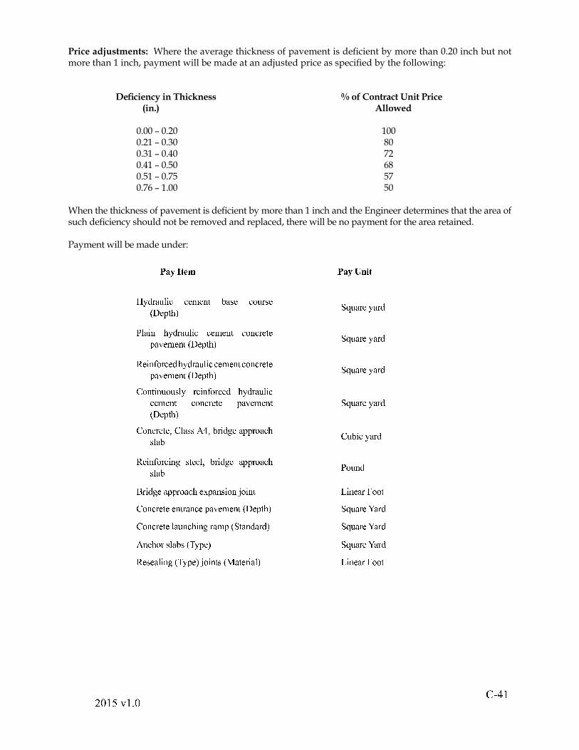
! " #$ % # & ' # ( %
Price adjustments: Where the average thickness of pavement is de! cient by more than 0.20 inch but not more than 1 inch, payment will be made at an adjusted price as speci! ed by the following:
De! ciency in Thickness % of Contract Unit Price (in.) Allowed
0.00 � 0.20 100 0.21 � 0.30 80 0.31 � 0.40 72 0.41 � 0.50 68 0.51 � 0.75 57 0.76 � 1.00 50
When the thickness of pavement is de! cient by more than 1 inch and the Engineer determines that the area of such de! ciency should not be removed and replaced, there will be no payment for the area retained.
Payment will be made under:) * + , - . / ) * + 0 1 2 -3 4 5 6 7 8 9 : ; ; < = < > ? @ 7 A < ; B 8 6 A <C D < E ? F G H I 8 7 6 < 4 7 6 5J 9 7 : > F 4 5 6 7 8 9 : ; ; < = < > ? ; B > ; 6 < ? <E 7 K < = < > ? C D < E ? F G H I 8 7 6 < 4 7 6 5L < : > M B 6 ; < 5 F 4 5 6 7 8 9 : ; ; < = < > ? ; B > ; 6 < ? <E 7 K < = < > ? C D < E ? F G H I 8 7 6 < 4 7 6 5N B > ? : > 8 B 8 A 9 4 6 < : > M B 6 ; < 5 F 4 5 6 7 8 9 : ;; < = < > ? ; B > ; 6 < ? < E 7 K < = < > ?C D < E ? F G H I 8 7 6 < 4 7 6 5N B > ; 6 < ? < O N 9 7 A A P Q O @ 6 : 5 R < 7 E E 6 B 7 ; FA 9 7 @ N 8 @ : ; 4 7 6 5L < : > M B 6 ; : > R A ? < < 9 O @ 6 : 5 R < 7 E E 6 B 7 ; FA 9 7 @ J B 8 > 5S 6 : 5 R < 7 E E 6 B 7 ; F < T E 7 > A : B > U B : > ? V : > < 7 6 W B B ?N B > ; 6 < ? < < > ? 6 7 > ; < E 7 K < = < > ? C D < E ? F G H I 8 7 6 < X 7 6 5N B > ; 6 < ? < 9 7 8 > ; F : > R 6 7 = E C H ? 7 > 5 7 6 5 G H I 8 7 6 < X 7 6 5P > ; F B 6 A 9 7 @ A C Y 4 E < G H I 8 7 6 < X 7 6 5L < A < 7 9 : > R C Y 4 E < G U B : > ? A C Z 7 ? < 6 : 7 9 G V : > < 7 6 W B B ?

! " # # $ % & ' % ( $
Division IV
Bridges And Structures
! " #$ % & ' ( & ) %
SECTION 401--STRUCTURE EXCAVATION
401.01--Description.
This work shall consist of excavating and back! lling or disposing of material necessary for constructing substructures and superstructures of new bridges and altering existing bridges in accordance with the requirements of these speci! cations and in reasonably close conformity with the lines and grades shown on the plans or as established by the Engineer.
401.02--Materials.
(a) Back! ll shall be approved by the Engineer and shall be free from large or frozen lumps, wood, or rocks more than 3 inches in their greatest dimension or other extraneous material. Porous back! ll shall conform to the requirements of Section 204.
(b) Pipe underdrains shall conform to the requirements of Section 232.
401.03--Procedures.
Excavated material shall generally be used for back! lling and constructing embankments over and around the structure. Surplus or unsuitable material shall be disposed of in a place and manner such that it will not affect or re-enter streams or otherwise impair the hydraulic ef! ciency or appearance of the structure or any part of the roadway.
Where practicable, substructures shall be constructed in open excavation and, where necessary, the excavation shall be sheeted, shored, braced, or protected by other means. If footings can be placed in the dry without the use of sheeting or cofferdams, forms may be omitted with the approval of the Engineer and the entire excavation ! lled with concrete to the required elevation of the top of the footing. When forms are eliminated, measurement and payment for structure excavation and concrete will be on a plan quantity basis wherein no adjustments will be made.
Unless tremie placement of concrete is speci! ed, foundations for footings shall be kept free from standing or surface water until concrete and back! ll operations have been completed. However, if the foundation is rock or the footing is supported on piles, other than for shelf abutments, dewatering need be performed only during concrete and back! ll operations.
(a) Preserving the Channel: Excavation shall not be performed outside caissons, cribs, cofferdams, or sheet piles. The natural stream bed adjacent to the structure shall not be disturbed. Material deposited in the stream area because of the Contractor�s operations shall be removed, and the stream area shall be freed from obstructions caused by the Contractor�s operations.
Prior to beginning work, the Contractor shall submit a plan that shall include the speci! c location of temporary structures or other obstructions that will constrict the stream " ow, a description of construction activities that will contribute to constricting the stream " ow, the dimensions and number of temporary structures and constrictions that are to be placed in the stream at any one time, and a dimensional elevation view of the stream and proposed temporary structures and constrictions.
(b) Depths of Foundations: Elevations denoting the bottom of footings shown on the plans shall be considered approximate only. Foundations shall not be considered satisfactory until approved by the Engineer.
When requested, the Contractor shall explore foundations by rod soundings or drillings to determine, to the satisfaction of the Engineer, the adequacy for the foundations to support
! " " # $ % & ' % ( $
the structure. If explorations indicate that satisfactory foundations can be obtained, variations from plan depths to foundations of open column abutments and solid or column piers shall be made only by adjusting stem lengths. Footing depths shown on the plans shall be considered minimum depths. Plan depths of concrete for footings may be increased not more than 24 inches at points of local irregularity over solid rock foundations.
Variations from plan depths to foundations of solid or deep curtain-wall abutments shall be made only by adjusting the depths of footings. Plan depths shall be considered minimum depths and shall not be exceeded by more than 3 feet.
If explorations reveal that foundations or subfoundations are inadequate for the structure, or are not within the limits of permissible variation from the bottom of footing elevations, the Engineer shall be consulted for instructions for further action or redesign.
(c) Preparing Foundations for Footings: Hard foundation material shall be freed from loose material, cleaned, and cut to a ! rm surface, either level, stepped, or serrated as directed by the Engineer. Seams shall be cleaned out and ! lled with concrete as directed by the Engineer.
When concrete is to rest on an excavated surface other than rock, the bottom of the excavation shall not be disturbed. The ! nal removal of foundation material to grade shall not be performed until just prior to concrete placement.
When the elevation of the bottom of a footing is above the level of the original ground, the footing shall not be placed until the approach embankment has been placed and compacted to the elevation of the top of the footing and excavation has been performed through the embankment to the elevation of the bottom of the footing. When a footing is to be placed over material subject to movement because of pressure from overlying or adjacent ! ll, the footing or piles for the footing shall not be placed until after the ! ll has been placed and compacted. Excavation for shelf abutment footings shall be limited to a perimeter extending not more than 18 inches outside the neat lines at the bottom of the footing.
When the material on which a foundation is to be placed using piles is declared unsatisfactory by the Engineer, the excavation shall be undercut for a depth of 6 to 12 inches as directed and back! lled with crusher run aggregate, select borrow, or other material approved by the Engineer.
(d) Holes for Drilled-In Caissons: Foundation bearing areas shall be cut to an approximately level surface except that they may be stepped or serrated on hard rock. If material is encountered that is not suf! ciently cohesive to maintain the proper diameter of the hole, casing shall be used.
(e) Cofferdams: Cofferdams for foundation construction shall be as watertight as practicable and carried to a depth that will allow them to function properly without displacement. The interior dimensions of cofferdams shall be such as to give suf! cient clearance for the construction of forms and inspection of their exteriors and permit pumping from outside the forms. Cofferdams that are tilted or moved laterally during sinking shall be realigned to provide the required clearance.
If conditions are encountered that render it impracticable to dewater the foundation, the Contractor may be required to construct a concrete foundation seal of the dimensions necessary to ensure that the balance of the concrete can be placed in the dry. When weighted cofferdams are employed and the weight is used to overcome the hydrostatic pressure acting against the bottom of the foundation seal, anchorage, such as dowels or keys, shall be provided to transfer the entire weight of the cofferdam into the foundation seal. Cofferdams that are to remain in place shall be ported at the low water level.
! " #$ % & # ' & ( %
Cofferdams shall be constructed in a manner to prevent damage to fresh concrete from a sudden rising of the stream and prevent damage to the foundation by erosion. Timber or bracing left in cofferdams shall not extend into the substructure concrete.
Cofferdams, including sheeting and bracing, shall be removed after completion of the substructure in a manner that will not disturb or damage the ! nished concrete.
(f) Pumping: Pumping from the interior of a foundation enclosure shall be performed in a manner to preclude the possibility of water moving through any fresh concrete. Pumping will not be permitted during concrete placement or for at least 24 hours thereafter unless it is performed from a suitable sump separated from the concrete work.
(g) Protecting Existing Structures or Utilities: When foundations are located such that excavation may endanger or interfere with an existing structure or utility, the location of bracing and method of protection shall be subject to approval by the owner of the structure or utility.
(h) Inspection: After each excavation has been completed, the Contractor shall notify the Engineer and request his inspection and approval. Concrete shall not be placed until the depth of the excavation and the character of the foundation material have been approved.
(i) Back! lling: Excavated spaces that are not occupied by abutments, piers, or other permanent work shall be back! lled with soil to the surface of the surrounding ground. Back! ll shall be uniformly compacted, and the top surface shall be neatly graded.
The ! ll around the perimeter of abutments, wing walls, and retaining walls shall be placed in horizontal layers not more than 6 inches in loose thickness and compacted at ±20 percent of optimum moisture to a density of at least 95 percent as compared to the theoretical maximum density as de! ned in Division II. Tests for compliance with density requirements will be performed in accordance with the requirements of VTM-12. As the work progresses, back! ll in front of units shall be placed and compacted in horizontal layers to the same elevation as the layers behind units until the ! nal elevation in front is reached. Back! ll shall be placed in a manner to prevent wedging action against the concrete. Slopes bounding excavation for abutments, wingwalls, or retaining walls shall be destroyed by stepping or serrating. Jetting of the ! ll behind abutments, wingwalls, or retaining walls will not be permitted.
Fills and back! lls around piers not included in the roadway prism shall be constructed in uniformly compacted layers and placed alternately to maintain a uniform elevation on both sides of the structure. However, the density requirement will be waived.
Provision shall be made for drainage of back! ll. Two-inch crusher run aggregate, conforming to the requirements of Section 205, shall be placed at the back of weep holes to extend 18 inches behind the entrance to the hole, 18 inches above the elevation of the bottom of the hole, and 18 inches laterally on each side of the center line of the hole.
Back! ll shall not be placed against abutments or wingwalls until concrete has been in place 14 days, exclusive of days on which the average high-low air temperature is below 40 oF in the shade or until test cylinders have attained a compressive strength equal to 93 percent of the required 28-day design compressive strength.
Back! ll shall be placed as soon as practicable following attainment of the required compressive strength but not later than 30 days after concrete placement. Excavation openings shall be maintained as dry as practicable at the time of back! lling. Back! ll shall be placed in a manner to deter impoundment of water and facilitate existing drainage.
! " # $ % & ' ( & ) %
(j) Filled Spandrel Arches: Fill for spandrel arches within 1 1/2 times the height of the arch shall be placed in a manner to load the ring uniformly and symmetrically. Fill material shall be homogeneous soil and shall be placed in horizontal layers not more than 6 inches in loose thickness, compacted in accordance with the requirements of Section 303.04(h), and brought up simultaneously from both haunches. Wedge-shaped sections of ! ll material against spandrels, wings, or abutments will not be permitted.
(k) Approach Embankment: Approach embankment shall be constructed in accordance with the requirements of Section 303.04(h).
401.04--Measurement and Payment.
Structure excavation will be measured in cubic meters of material removed from the limits of vertical planes within 18 inches outside the neat lines of footings or of neat work that does not have footings directly beneath it, such as curtain walls or cantilevered wing walls. It will be measured from the surface of the original ground or approach roadway down to the bottom of the foundation shown on the plans or such foundation as the Engineer may approve, or down to 18 inches below the bottom of the neat work not directly over footings, or to the top of existing concrete where excavation is to permit placing new concrete over existing concrete.
When speci! ed on the plans, structure excavation will include material removed outside the limits speci! ed for the substructure, in the vicinity of the substructure on which a superstructure rests, and to a depth of 18 inches below the lowest beam or bottom of the slab of the superstructure, or to such depth as shown on the plans. The width of such excavation shall be limited to 18 inches outside the exterior beams or edges of the slab or as shown on the plans.
Excavation above the bottom of a proposed channel change or roadway template or an overpassed road will not be included as structure excavation.
Structure excavation will be paid for at the contract unit price per cubic yard. This price shall include clearing and grubbing, sheeting, shoring, bracing, placing and compacting back! ll, dewatering, furnishing and placing aggregate for weep holes, disposing of unsuitable or surplus material, and clearing the channel of obstructions caused by construction operations.
Excavation for drilled-in caissons will be measured in linear feet of drilled hole from the existing ground to the bottom of the ! nished hole as measured along the center line of the hole and will be paid for at the contract unit price per linear foot. This price shall include drilling, under reaming, casing, and preparing the hole.
Furnishing and placing back! ll will be included in the price for structure excavation and will not be measured for separate payment unless speci! c material is required by the Engineer and no suitable material is available within the construction limits. When speci! c material is required for back! ll by the Engineer, measurement and payment will be in accordance with the requirements of Section 104.03.
Porous back! ll, when a pay item, will be measured in cubic yards of material within the limits shown on the plans or as otherwise directed by the Engineer and will be paid for at the contract unit price per cubic yard.
Pipe underdrains, when a pay item, will be measured in linear feet and will be paid for at the contract unit price per linear foot.
Unsuitable materials removed below the plan foundation will be measured and paid for as structure excavation.
! " #$ % ! " # %
Foundation seals required by the Engineer and that are properly placed for structural adequacy as a part of the planned footing will be accepted as part of the permanent footing. Measurement and payment will be in accordance with the requirements of Section 404.08. Foundation seals that are not required by the Engineer will be included in the price for structure excavation.
Clearing and grubbing within the area de! ned by lines connecting the extremities of the substructure units, regardless of whether excavation is involved, shall be included in the price for structure excavation unless otherwise speci! ed in the Contract.
Cofferdams will be measured in units of each per foundation and will be paid for at the contract unit price per each. This price shall include furnishing, erecting, maintaining, and removing.
Payment will be made under:
Pay Item Pay Unit
Structure excavation Cubic yard
Drilled holes Linear Foot
Porous back! ll Cubic yard
Pipe underdrain (Size) Linear Foot
Cofferdams Each
SECTION 404--HYDRAULIC CEMENT CONCRETE OPERATIONS
404.01--Description.
This work shall consist of furnishing and placing hydraulic cement concrete in accordance with these speci! cations and in reasonably close conformity with the dimensions, lines, and grades shown on the plans or as established by the Engineer.
404.02--Materials.
(a) Concrete shall conform to the requirements of Section 217. Aggregate used in concrete for bridge decks shall be nonpolishing.
(b) Curing materials shall conform to the requirements of Section 220.
(c) Concrete admixtures shall be used as speci! ed in Section 217.
(d) Corrugated metal bridge deck forms shall be galvanized steel conforming to the requirements of ASTM A653, Grade SS40, SS50, or SS80 and shall be coating designation G165. Supports, closures, and other fabricated parts shall conform to the requirements of ASTM A653, Grade SS33, SS40, or SS80 and shall be coating designation G165.
(e) Prestressed concrete deck panels shall conform to the requirements of Section 405 except as speci! ed herein.
(f) Anchor bolts shall conform to the requirements of Section 226.
(g) Reinforcing steel shall conform to the requirements of Section 223.
(h) Waterstops shall conform to the requirements of Section 212.
! " # $ % & ' ( & ) %
404.03--Procedures.
(a) Forms: On concrete beam bridges, the Contractor shall have the option of using corrugated metal bridge deck forms, prestressed deck panels, or wood forms to form that portion of bridge decks between beams unless otherwise speci! ed on the plans. On steel beam bridges, the Contractor shall have the option of using corrugated metal bridge deck forms or wood forms to form that portion of bridge decks between beams or girders unless otherwise speci! ed on the plans. However, corrugated metal forms and prestressed deck panels shall not be used to form overhangs or portions of slabs where a longitudinal joint occurs between beams or girders.
Devices for supporting forms of any type shall not be welded to steel beams or girders unless speci! ed on the plans.
Formwork shall be mortartight and of suf! cient rigidity to prevent distortion attributable to the pressure of the concrete and other loads incidental to construction operations.
Forms for exposed surfaces shall have a form liner of an approved type and shall be mortartight. Forms for exposed surfaces below the bottom of slabs of bridges, including substructures, and on endwalls and wing walls of culverts down to an elevation of 1 foot below low water or 2 feet below the ! nal ground line above water shall be faced with metal, plyboard, or other approved smooth-faced material constructed to provide a minimum of joints and prevent leakage. Concrete shall present a uniform and smooth surface without requiring touch-up or surface ! nishing upon removal of forms. Uneven joint protrusions of more than 1/8 inch shall be removed. Forms shall be ! lleted ¾ inch at sharp corners and given a bevel or draft in the case of projections, such as girders and copings, to ensure easy removal.
Metal ties or anchorages within the form shall be constructed to permit their removal to a depth of at least 1 inch from the face without damage to the concrete. If ordinary wire ties are permitted, wires shall be cut back at least ¼ inch from the face of the concrete with chisels or nippers upon removal of forms. Fittings for metal ties shall be of such design that cavities left upon their removal will be the smallest size possible. Cavities shall be ! lled with cement mortar, and the surface left sound, smooth, even, and uniform in color.
Forms shall be set and maintained true to line. When forms appear to be unsatisfactory, either before or during concrete placement, the Engineer may order the work stopped until defects have been corrected.
The shape, strength, rigidity, watertightness, and surface smoothness of reused forms shall be maintained at all times. Warped or bulged lumber shall be resized before being reused.
For narrow walls and columns where the bottom of the form is inaccessible, the lower form boards shall be left loose so that they may be removed for cleaning immediately before concrete placement.
Forms shall be treated with an approved oil or form-coating material or thoroughly wetted with water immediately before concrete placement. For rail or other units with exposed faces, forms shall be treated with an approved oil or form-coating material to prevent adherence of concrete. Material that will adhere to or discolor concrete shall not be used.
Forms shall be maintained at a temperature that will not adversely affect curing of concrete.
Formed voids in concrete shall be of accurate dimensions and locations so that the thickness of surrounding concrete shall not be reduced from plan dimensions.
! " #$ % & ' ( & ) %
Methods of positioning void forms and placing surrounding concrete shall be subject to the approval of the Engineer prior to their use.
Bridge deck slabs shall be constructed in a manner so that the thickness of the ! nished slab shall be not less than the thickness shown on the plans or more than the thickness plus ½ inch.
1. Corrugated metal bridge deck forms: If the Contractor elects to use corrugated metal bridge deck forms, he shall submit details of the forms, including fabrication and erection details, to the Engineer for approval in accordance with the requirements of Section 105.02. Forms shall be designed and erected in accordance with the following:
a. Design: The thickness of forms shall be at least 0.037 inch (20 gage). The unit working stress in the sheet metal and supporting units shall be not more than 0.725 of the speci! ed minimum yield strength of the material furnished. In no case shall it be more than 36,000 pounds per square inch. The maximum stress under a design load equal to the weight of the forms and plastic concrete plus a construction live load of 50 pounds per square inch shall be not more than the unit working stress for the material furnished. De" ection of forms under the weight of the form, plastic concrete, and reinforcement shall be not more than 1/180 of the span of the forms or ½ inch, whichever is less. In no case shall the loading be less than 120 pounds per square foot total.
When the actual dead load attributable to the use of metal bridge deck forms is more than the design allowance for construction tolerances and methods shown on the plans, the Contractor shall strengthen the beams or girders to the extent necessary to maintain the design live load rating of the bridge and shall submit supporting information and calculations to the Engineer for review.
b. Erection: Forms shall be installed in accordance with reviewed fabrication and erection plans. Field cutting of forms, supports, and closures at expansion joints, diaphragms, and abutments in skewed areas or in any area where girders or beams are not parallel shall be performed with saws or shears. The outstanding leg of the support angle, channel, or other device shall be not more than 3 inches.
Form sheets shall not rest directly on the top of the stringer or " oor beam " anges. Sheets shall be securely fastened to form supports and shall have a minimum bearing length of 1 inch at each end. Form supports shall be placed in direct contact with the stringer or " oor beam " ange by hangers or clips. Attachment of the forms to the form supports shall be made by permissible welds, screws, clips or other approved means. Fasteners along the ends and edges of form sheets shall be spaced at intervals not to exceed 18 inches.
Welding and welds shall conform to the requirements of Section 407.04 except that 1/8 inch ! llet welds will be permitted.
Permanently exposed form metal whose galvanized coating has been damaged shall be repaired in accordance with the requirements of Section 233.
! " # $ # % " & % ' #
Corrugated metal forms shall be positioned such that the speci! ed cover for the reinforcing steel and minimum design slab thickness are maintained above crests of the corrugation.
Transverse construction joints shall be located at the bottom of a " ute, and ¼ inch weep holes shall be ! eld drilled at not more than 12 inches on center along the line of the joint.
Closures at edges of forms parallel to beams or girders shall be made by crimping corrugations. Closures at skewed ends may be of the serrated or channel type.
The design span of the sheet shall be the clear span of the form plus 2 inches measured parallel to form " utes.
The permissible form camber shall be based on the actual dead load condition. Camber shall not be used to compensate for de" ection in excess of the foregoing limits.
Physical design properties shall be computed in accordance with the requirements of AISI�s speci! cations for the design of cold-formed steel structural units.
c. Inspection: After concrete has been in place for at least 2 days, the Contractor shall sound at least 50 percent of the area of at least 25 percent of the individual form panels using a moderate blow administered with a carpenter�s hammer. Individual form panels to be sounded will be selected randomly by the Engineer. Areas of questionable soundness shall be exposed by removing forms. The amount of sounding and form removal required will be adjusted as the work progresses according to conditions detected by the investigation. When procedures, materials, or equipment used during placement of concrete warrant additional inspection of the underside as determined by the Engineer, the Contractor shall remove at least one form panel at each location selected by the Engineer. If the initial inspection reveals inferior workmanship or unsatisfactory material as determined by the Engineer, additional panels shall be removed to ascertain the extent of the de! ciency. The Contractor will not be required to replace metal forms at locations where sections of forms are removed for inspection purposes. However, adjacent metal forms and supports shall be repaired to the extent necessary to render their attachment secure.
The Contractor shall provide facilities required for the safe and convenient conduct of the Engineer�s inspection.
2. Prestressed deck panel forms: If the Contractor elects to use prestressed deck panel forms, he shall redesign the deck slab in accordance with the requirements of AASHTO�s Standard Speci! cations for Highway Bridges and the interim speci! cations as modi! ed by the Department and shall submit the redesign of the deck slab, reinforcing steel schedule, design calculations, and working drawings to the Engineer for acceptance in accordance with the requirements of Section 105.02. Working drawings shall show the permissible construction live load. The Contractor�s submittal shall be made at least 60 days prior to the time necessary for ordering materials for the work.
a. Design: The following conditions shall apply to the redesign of the cast-in-place deck slab:
! " #$ % # " & # ' %
1. The size, spacing, and area of transverse reinforcing steel in the top of deck slabs shall be not less than that shown on the plans. The transverse reinforcing steel shown on the plans in the bottom of the deck slab shall be eliminated.
2. Longitudinal reinforcing steel shown on the plans in the bottom of the deck slab shall be replaced by reinforcing bars having the identical size and spacing as the main transverse reinforcing bars in the deck slab. These bars shall be placed ½ inch clear above the top of the deck panels. Longitudinal reinforcing steel shown on the plans in the top of the deck slab may be eliminated, except over intermediate supports of continuous spans, provided adequate tie bars having no more than 24 inch spacing are used for securing top transverse steel. The distance from the face of the concrete to the center of the top layer of main reinforcing steel shall be 2 ¾ inches.
3. Shear connectors on steel beams or girders and vertical reinforcement in prestressed concrete beams may be adjusted to facilitate placing prestressed deck panels.
4. The design for deck panels shall provide for the same total slab thickness as shown on the plans.
5. When epoxy-coated steel is speci! ed on the plans, reinforcing steel in the cast-in-place section of the slab shall be epoxy coated.
6. The depth of intermediate diaphragms for prestressed concrete beams shall be modi! ed to provide clearance between the panel and diaphragm.
7. Lifting devices installed in panels for handling may be left in place provided they do not project closer than 2 inches to the ! nished deck surface.
8. Panels will not be allowed over the end supports for bridges skewed more than 15 degrees. End sections of slabs shall be cast the full depth shown on the plans.
9. Panels shall be roughened in the direction parallel to the strands.
The following conditions shall apply to the design of the deck panels:
1. The strand size shall be not more than 3/8 inch.
2. A cover of at least 1 ½ inches shall be provided on the bottom of deck panels for prestressing strands and reinforcing steel.
3. The cracking load a unit can sustain shall be at least 1.2(D) + 1.5(L + I) without the concrete tensile stress exceeding 7.5 f�c where D = dead load; L + I = live load + impact; and f�c = the 28-day design compressive strength of concrete in pounds per square inch.
4. At least 0.11 square inch per foot of reinforcing steel transverse to strands shall be provided in panels.
5. The length of the panel in the direction of strands shall be at least 5 feet 2 inches.
! " # # $ % " & % ' $
6. Strands shall project at least 3 inches from the concrete at both ends of the panel.
7. Mild reinforcing steel in the deck panel, including tie bars and reinforcing bars used for panel-lifting purposes, shall be epoxy coated. Bar supports shall conform to the requirements of Section 406.03(d).
Panel sides that are parallel to the strands may be cast to provide full-depth contact with the adjacent panel or cast with angular sides that, when installed with an adjacent panel, will form a V-shaped joint, which shall be mortartight at its base.
b. Erection: Precast bridge deck panels shall be erected in accordance with the accepted working drawings and with the strands transverse to the longitudinal direction of the beams. Panels shall be tightly butted together and shall be mortartight, with panel joints staggered on each side of the supporting beam. Panel joints that are not in full contact or that are not mortartight shall be sealed by epoxy mortar or other approved method at the Contractor�s expense.
Prior to placement of the deck surface concrete, foreign material detrimental to achieving a bond shall be removed by sandblasting, waterblasting, or other approved methods. The top surface of deck panels shall be thoroughly and continuously water soaked for at least 1 hour prior to placement of deck surface concrete. Puddles of standing water shall be removed prior to placement of deck surface concrete. Panels shall be supported by one of the following methods to provide the same total slab thickness as shown on the plans:
1. nonshrink cement mortar bed 3 ± ¼ inches in width with a thickness of at least ½ inch conforming to the requirements of Section 218 except that the compressive strength shall be 5,000 pounds per square inch. When shims are used to construct the mortar bed, they shall be removed prior to placement of the deck concrete.
2. galvanized steel support angles having an outstanding leg width of at least 1 inch and a thickness of at least 1/8 inch or 10 gage. The unit working stress shall be not more than 72 1/2 percent of the speci! ed minimum yield strength of the material furnished but in no case more than 36,000 pounds per square inch. A strip of 1/8 inch asphalt felt the same width as the angle shall be placed between the support angle and the deck panel. When cast in place slab concrete is to be used to provide permanent support for panels, concrete shall be placed in continuous strips over the girders and consolidated to ensure concrete penetrates under the panels, prior to placing concrete on top of the panels. Slab overlay concrete shall penetrate under the panels to a width of 3 ± ¼ inch and a thickness of at least 1 ½ inch to provide the rigid support for the panels. If this method of support is used, bridge seat elevations shall be adjusted as necessary at the Contractor�s expense.
3. Welding and welds shall conform to Section 407.04, except that 1/8 inch ! llet welds will be permitted. Welding to beam or girder " anges will not be permitted.
! " #$ % & " ' & ( %
Regardless of the method of support used, the Contractor shall ensure the stability of the deck panels until the slab overlay concrete has set.
(b) Falsework and Centering: The Contractor shall have a Professional Engineer (holding a valid license to practice engineering in the Commonwealth of Virginia) inspect the completed falsework assembly supporting a bridge superstructure prior to placing loads. The Professional Engineer shall provide a certi! cation, based upon visual inspection of the completed falsework assembly, that the falsework assembly conforms to the approved working drawings. However, such certi! cation shall not require an exhaustive inspection or testing, nor shall it make the Professional Engineer liable for any de! ciencies in workmanship or materials by the Contractor, or for such conditions that cannot be ascertained from a visual inspection.
Falsework shall be designed and constructed to provide the necessary rigidity and support the loads without appreciable settlement or deformation. The Contractor may be required to employ screw jacks or hardwood wedges to take up settlement in the formwork either before or during concrete placement. A design weight of 150 pounds per cubic foot shall be assumed for fresh concrete.
Falsework that cannot be founded on a satisfactory footing shall be supported on piles that are spaced, driven, and removed in a manner approved by the Engineer.
Falsework shall be set in a manner so that after its removal the ! nished structure will have the ! nished grade speci! ed or indicated on the plans. Correction for dead-load de" ection of cast-in-place concrete beams and slab spans shall be provided for by applying an upward parabolic camber having an ordinate at midspan of 1/8 inch per 10 feet of span length.
Falsework-supporting elements shall remain in place until concrete in the element has attained at least the minimum 28-day design compressive strength.
Arch centering shall be constructed according to centering plans approved by the Engineer. Provision shall be made by means of suitable wedges, sand boxes, or other devices for gradual lowering of centers and rendering the arch self-supporting. When directed by the Engineer, centering shall be placed on approved jacks to take up and correct settlement that may occur after concrete placement has begun.
(c) Placement and Consolidation: Individual placements of more than 25 cubic yards of concrete shall be at the following rate:
Quantity (yd3) Min. Placement Rate
26-80 25%/hr Over 80 20 yd3/hr
If corrugated metal bridge deck forms are used in lieu of removable forms, concrete placement shall proceed in the direction opposite that of form placement.
Concrete shall be placed as soon as practicable after forms are prepared and excavation is completed. Water shall be removed from excavations before concrete is placed. Flowing water within the excavation shall be diverted outside concrete areas to a sump.
Before concrete is placed, sawdust, chips, dirt, and other debris and temporary struts and braces shall be removed from the space to be occupied by concrete. Removable forms shall be thoroughly wetted, oiled, or treated with an approved form-coating material. The depth and character of foundations and the placing of reinforcing steel shall have been approved by the Engineer.
! " # $ % & " ' & ( %
Concrete shall be placed in forms immediately after mixing. Concrete that does not reach its ! nal position in forms within the time speci! ed in Section 217 shall not be used. The method of placement shall be such as to avoid the possibility of segregating ingredients and displacing reinforcement or void forms.
The use of long chutes for conveying concrete from the mixing plant to forms will be permitted only with the written permission of the Engineer. If chutes are allowed and the quality of concrete as it reaches the forms or the methods of placing it therein are not satisfactory, the Contractor shall, upon direction from the Engineer, discontinue the use of chutes and re-equip his operation for placing concrete in a satisfactory manner.
Where steep slopes are required, chutes shall be equipped with baf" e boards. When pipes are used, they shall be kept full of concrete and have their lower ends buried in fresh concrete where necessary to prevent an excessive " ow rate. Chutes, troughs, and pipes shall be kept clean and free from coatings of hardened concrete by thorough " ushing with water after each run. Water used for " ushing shall be discharged clear of concrete in place and ! ltered prior to entry into state waters. Open troughs and chutes shall be metal or lined with metal and shall extend as nearly as possible to the point of deposit. When discharge must be intermittent, a hopper or other device for regulating discharge shall be provided.
Dropping concrete a distance of more than 5 feet or depositing a large quantity at any point and running or working it along forms will not be permitted. However, the 5 foot limitation will not apply to dropping concrete into forms for walls of box culverts, catch basins, drop inlets, or end walls unless there is evidence of segregation.
Concrete placement shall be regulated so that pressures caused by fresh concrete shall be not more than those used in the design of forms.
Embedded materials shown on the plans shall be installed during each stage of concrete operations and suitably supported and maintained in the correct position. Reinforcement shall be placed in accordance with the requirements of Section 406.03(d).
Care shall be taken to ! ll each part of a form by placing concrete as near its ! nal position as possible, working coarse aggregates back from forms, and moving concrete under and around reinforcing bars without displacing them. After concrete has taken its initial set, care shall be taken to avoid jarring forms or placing strain on ends of projecting reinforcement.
Concrete shall be thoroughly consolidated during and immediately following placement. Consolidation shall be accomplished by mechanical vibration subject to the following provisions:
1. Vibration shall be internal to the concrete but not applied directly to reinforcement or formwork.
2. Vibrators shall be of a type and design approved by the Engineer.
3. The intensity of vibration shall visibly affect a mass of concrete over a radius of at least 18 inches.
4. The Contractor shall provide a suf! cient number of vibrators to consolidate each batch immediately after it is placed in forms.
5. Vibrators shall be manipulated to work concrete thoroughly around reinforcement and embedded ! xtures and into corners and angles of forms. Vibration shall
! " "# $ % " & % ' $
be applied at the point of deposit and in the area of the freshly placed concrete. Vibrators shall not be pulled through concrete and shall be inserted and withdrawn slowly and maintained nearly vertical at all times. Vibration shall be of suf! cient duration and intensity to consolidate concrete thoroughly but shall not be continued so as to cause segregation. Vibration shall not be continued at any one point to the extent that localized areas of grout are formed. Application of vibrators shall be at points uniformly spaced and not further apart than twice the radius over which the vibration is visibly effective.
6. Vibration shall not be applied directly or indirectly to sections or layers of concrete that have hardened to the degree that it ceases to be plastic under vibration. Vibration shall not be used to make concrete " ow in forms, and vibrators shall not be used to transport concrete in forms.
7. Vibration shall be supplemented by such spading as is necessary to ensure smooth surfaces and dense concrete along form surfaces and in corners and locations inaccessible to vibrators.
8. These speci! cations shall apply to ! ller concrete for steel grid " oors except that vibration shall be applied to the steel.
9. These speci! cations shall apply to precast piling, concrete cribbing, and other precast units except that the manufacturer�s methods of vibration may be used if approved by the Engineer.
When vibrating is not practicable, concrete shall be consolidated and its faces well spaded by continuous working with a suitable tool in a manner acceptable to the Engineer.
Concrete shall be placed in continuous horizontal layers not more than 12 inches in thickness. However, slabs shall be placed in a single layer. When it is necessary in an emergency to place less than a complete horizontal layer in one operation, the layer shall terminate in a vertical bulkhead. In any given layer, separate batches shall follow each other so closely that each one shall be placed and consolidated before the preceding one has taken initial set. Each layer of concrete shall be left rough to secure ef! cient bonding with the layer above. A succeeding layer placed before the underlying layer has become set shall be consolidated in a manner to prohibit the tendency to produce a construction joint between layers.
Layers placed at the end of one day�s work or prior to temporarily discontinuing operations shall be cleaned of laitance and other objectionable material as soon as the surface has become suf! ciently ! rm to retain its form. The top surface of concrete adjacent to forms shall be smoothed with a trowel.
Horizontal layers located to produce a construction joint at a location wherein a feather edge might be produced in the succeeding layer shall be formed by inset formwork so that the succeeding layer will end in a body of concrete having a thickness of at least 6 inches.
The work on any section or layer shall not be stopped or temporarily discontinued within 18 inches below the top of any face unless the details of the work provide for a coping having a thickness of not more than 18 inches, in which case the construction joint may be made at the underside of the coping at the option of the Engineer.
Care shall be taken when placing concrete to avoid coating reinforcing steel, structural steel, forms, and other items that extend into areas to be involved in a subsequent placement. If coating of steel does occur, no attempt shall be made to remove the mortar until after the concrete steel bond of the earlier placement has developed suf! ciently to withstand
! " # $ % & " ' & ( %
a cleaning operation. Any coating of mortar on deformed bars that cannot be removed by hand brushing with a wire bristle brush or a light chipping action will not have to be removed.
The method and manner of placing concrete shall be regulated so as to place construction joints across regions of low shearing stress and in locations that will be hidden from view to the greatest extent possible.
Placing and consolidating concrete shall be conducted to form a compact, dense, impervious mass of uniform texture that will show smooth faces on exposed surfaces. Any section of concrete found to be defective shall be removed or repaired as directed by the Engineer.
If concrete operations are permitted to extend after sunset, the work area shall be brightly lighted so that all operations are plainly visible.
1. Culverts: Sidewalls of box culverts shall be carefully bonded to the base slab in accordance with (h) herein. Each wing shall be constructed as a monolith if possible. Construction joints, where unavoidable, shall be horizontal.
2. Girders, slabs, and columns: Concrete shall be placed by beginning at the center of the span and working toward the ends. Concrete in girders shall be placed uniformly for the full length of the girder and brought up evenly in horizontal layers.
The concrete " oor and girders for each span of concrete through girder spans and concrete in T-beams, slab spans, and deck girders shall be placed monolithically.
If the ! nished top surface of a concrete unit being placed is not level, care in the method of vibration, the use of low slump concrete, or other means shall be taken to prevent downgrade movement of newly placed concrete. Special attention shall be given to sloping slabs.
Concrete in columns shall be placed in one continuous operation. If cap forms are supported by falsework independent of columns or column forms or are otherwise designed so that no load is placed on columns, concrete may be placed in caps after concrete in columns has set for at least 12 hours. Otherwise, the requirements of Table IV-2 for columns carrying a load shall have been conformed to before concrete is placed in caps.
Concrete shall not be placed in the superstructure until column forms have been stripped suf! ciently to determine the character of concrete in columns.
(d) Pneumatic Placement: Pneumatic concrete placement will be permitted only when authorized by the Engineer and the method is approved by the Engineer. When permitted, placement shall be in accordance with the requirements of Section 412.
(e) Pumping: Placing concrete by pumping will be permitted only when authorized by the Engineer and provided concrete is pumped through a conduit system that is not aluminum. Equipment shall be arranged such that no vibrations that might damage freshly placed concrete will occur. Equipment shall be thoroughly cleaned prior to use. The operation of the pump shall be such that a continuous stream of concrete without air pockets is delivered. If concrete remaining in the pipe line is to be used, it shall be ejected in such a manner that there will be no contamination of concrete or separation of ingredients.
(f) Depositing Concrete Under Water: Concrete shall not be deposited in water except with the approval of the Engineer.
! " #$ % & " ' & ( %
Concrete placed in water shall be Class T3. Concrete shall be carefully placed in a compact mass in its ! nal position by means of a tremie or another approved method and shall not be disturbed after being deposited except as speci! cally provided herein. Still water shall be maintained at the point of placement.
A tremie shall consist of a tube having a diameter of at least 10 inches, constructed in sections having " anged couplings ! tted with gaskets. The discharge end shall be closed at the start of work and entirely sealed at all times. The tremie tube shall be kept full to the bottom of the hopper. When a batch of concrete is dumped into the hopper, the " ow of concrete shall be induced by slightly raising the discharge end, always keeping it in the placed concrete. Concrete seal shall be placed continuously from start to ! nish. Concrete shall be placed at a rate of at least 1 vertical foot per hour over the entire area of the seal course. The surface of concrete shall be maintained in a horizontal plane within a tolerance of 6 inches at all times during placement. The tremie shall be supported so that its discharge end is freely movable over the entire work area, or multiple tremies shall be used. Vibration shall be used only when deemed necessary by the Engineer. Supports for tremies shall permit rapid lowering of discharge ends when necessary to retard or stop the " ow of concrete. The method of placing the seal shall be subject to the approval of the Engineer prior to concrete placement.
Removal of water from cofferdams or other structures may proceed when the concrete seal has attained ! nal set. Laitance or other unsatisfactory material shall be removed from the exposed surface by scraping and chipping with pneumatic or hand tools to an extent that will expose the aggregate for good bond with the footing to be cast upon it but not to an extent that will damage the concrete.
(g) Construction Joints: Construction joints that are not detailed on the plans shall be placed as directed or approved by the Engineer. Shear keys or inclined reinforcement shall be used where necessary to transmit shear or bond the two sections together. Joints shall be constructed so that featheredging does not occur.
For construction joints in deck slabs, a 2 by 1 ½ inch shear key shall be provided between mats of reinforcing steel.
Construction joints against which earth ! ll is placed shall be protected by a heavy coat of asphalt conforming to the requirements of Section 213, applied for a distance of 3 inches on each side of the joint and continuous throughout its length.
In construction joints exposed to view, a waterstop conforming to the requirements of Section 213 shall be inserted. The waterstop shall be placed at least 3 inches from the face of concrete and shall extend at least 2 inches into each section of concrete.
Longitudinal or transverse construction joints may be used to facilitate placing concrete in continuous slab spans. Longitudinal joints shall be spaced so that each concrete placement will be at least 10 feet in width. Transverse joints shall be placed at the center lines of piers provided they are located infrequently, permitting simultaneous longitudinal screeding of as many spans as possible. Concrete shall be placed in one continuous operation between construction joints. The volume of concrete in any one placement shall be not less than the volume of concrete in one end span.
(h) Bonding Construction Joints: In joining fresh concrete to set concrete, the work already in place shall have its surface roughened thoroughly. Shavings, sawdust, and other loose and foreign material shall be removed. The surface shall be washed and scrubbed with wire brooms when necessary to remove substances that will interfere with bonding. Concrete of the preceding placement shall be thoroughly wetted prior to placement of the next unit of fresh concrete.
! " # $ % & " ' & ( %
For construction joints in deck slabs, the vertical face shall be sandblasted to expose the coarse aggregate. When epoxy-coated reinforcing steel is used, the epoxy coating shall be protected during sandblasting operations. Damaged areas of coated bars shall be repaired in accordance with the requirements of Section 223. Prior to placement of adjoining concrete, the vertical face shall be coated with epoxy, Type EP-4. After the concrete in the second placement has set, a V groove shall be formed along the top of the joint by sandblasting to a depth of at least ¼ inch and shall be sealed with epoxy, Type EP-5, low viscosity, conforming to the requirements of Section 243.
To bond successive courses, suitable keys shall be formed at the top of the upper layer of each day�s work and at other levels where work is interrupted. Keys shall be formed by inserting and subsequently removing beveled wood strips, which shall be saturated with water to induce swelling prior to insertion in fresh concrete. At the discretion of the Engineer, rough stone or steel dowels may be used in lieu of keys. Dowels shall extend an equal distance on each side of the construction joint. Prior to the inserting or driving of dowels into predrilled or preformed holes, holes shall be ! lled with hydraulic cement grout in the proportion of 1 part cement to 2 parts sand. The size and spacing of keys and dowels shall be determined by the Engineer.
(i) Concrete Exposed to Tidal Water: Concrete structures other than box culverts subject to the action of tidal water shall not have construction joints located within a zone 5 feet above to 5 feet below the elevation of the mean tide.
Concrete within 5 feet of the mean tide shall be cured in forms for 48 hours and allowed to dry for 5 days after forms are stripped. After drying, one coat of primer and four coats of asphalt, conforming to the requirements of Section 213, shall be applied during a period of 48 hours. Each coat shall be allowed to set before the succeeding one is applied. In lieu of primer and asphalt, the coating may consist of one coat of epoxy, Type EP-3B, followed by one coat of epoxy, Type EP-3T, and shall have a total thickness of at least 20 mils.
For precast concrete, protective coatings shall be applied in the same manner, but the seal coat shall be allowed to dry 4 days, or as long as necessary to harden, before handling.
Requirements for protective coating shall also apply to inside surfaces of box culverts that are subject to the ebb and " ood of tidal water.
Concrete exposed to the action of ice, drift, or other forces producing shock and abrasion shall be protected by encasing that portion of the exposed surface with a special sheathing or protective armor. Provision shall be made in the size of the original cofferdam for suf! cient clearance to permit access to the concrete surface for the installation and effective anchorage of the sheathing.
(j) Removing Formwork and Constructing Superimposed Elements: In the determination of the time for removing formwork and constructing superimposed elements, consideration shall be given to the location and character of the structure, the weather, other conditions in" uencing setting of concrete, and materials used in the mixture. Formwork shall include forms, braces, ties, guy wires, and other instruments of stabilization.
1. Formwork may be removed as follows:
a. Side forms or elements not immediately subjected to loading (for example: footings and walls or columns with height and width ratios less than 10:1 [h/w <10:1]: 48 hours or 30% concrete strength (f�c). For the purposes herein width will be considered the narrowest portion of the element measured horizontally across its surface.
! " #$ % & " ' & ( %
The time period noted for form removal shall begin at the completion of the concrete placement and is exclusive of hours when any portion of the concrete element�s surface is below 40ºF.
b. All other elements: 60% concrete strength (f�c).
2. Forming for superimposed elements may be as follows:
a. Elements not immediately subjected to loading (for example: footings and walls or columns with height to width ratios less than 10:1 [h/w <10:1]: 48 hours or 30% concrete strength (f�c). For the purposes herein width will be considered the narrowest portion of the element measured horizontally across its surface.
The time period needed for forming for superimposed elements shall begin at the completion of the concrete placement and is exclusive of hours when any portion of the concrete element�s surface is below 40ºF.
b. All other elements: 60% concrete strength (f�c).
3. Placing concrete in forms for superimposed elements shall not be done until concrete has attained 60% concrete strength (f�c) except for footings, where concrete may be placed when the footing has attained 40% concrete strength (f�c).
The Contractor may submit calculations to show that lower strength requirements may be used, but may not proceed to use these requirements before receiving written permission to do so.
Concrete strength (f�c) is the design minimum laboratory compressive strength at 28 days as speci! ed in Table II-17 Requirements for Hydraulic Cement Concrete for the class of concrete designated. If the time for removing formwork and forming for or placing concrete in superimposed elements is determined by control cylinder strengths, the Contractor will be permitted to perform these operations when the control cylinder strengths reach the values previously noted. Control cylinders shall be cured under conditions that are not more favorable than the most unfavorable conditions for the portion of the concrete the cylinders represent. The Contractor shall furnish molds, labor, and materials; make suf! cient test specimens; and transport specimens to the testing facility. Single-use wax paper, paper, plastic, or light-gage metal molds conforming to the requirements of ASTM C 470 may be used for making control cylinders. Control cylinders shall be molded under the observation of the Engineer. Tests for compressive strengths will be performed by or under the observation of the Engineer.
The concrete strengths and time periods noted herein for removing formwork or forming for or placing concrete in superimposed elements shall not apply to the use of equipment of other live loads on the structure. Stockpiling materials or using unauthorized equipment on the structure will not be permitted until conformance to the requirements of Section 404.03(m) has been obtained.
Methods of form removal that will overstress concrete shall not be used. Formwork and its supports shall not be removed without the approval of the Engineer. The Contractor shall ensure that proper curing as required by the Speci! cations is provided immediately after form removal.
For falsework requirements see Section 404.03(b).
! " # $ # % & ' % ( #
(k) Curing Concrete: The method of curing concrete shall be subject to the approval of the Engineer prior to mixing or placing concrete. When the atmospheric temperature is above 40 oF in the shade, concrete surfaces that are not protected by formwork and surfaces from which forms have been removed shall be cured using approved materials applied before the sheen disappears from fresh concrete or immediately upon removal of formwork. Concrete shall be cured for 7 days, regardless of the strength obtained with control cylinders. During this 7 day curing period, a curing agent or medium shall be used.
PE ! lm used for curing shall be white except that opaque or transparent PE ! lm may be used between November 1 and April 1.
When liquid membrane seal is used for curing grooved horizontal surfaces, the application rate shall be 100 to 150 square feet per gallon. The application rate for all other surfaces shall be 150 to 200 square feet per gallon. Application shall be such that an even, white continuous membrane is produced on the concrete surface.
If the atmospheric temperature falls below 40 oF in the shade, water curing shall be discontinued except when it is accomplished by " ooding as speci! ed herein. Curing shall be immediately resumed using insulated blankets or other approved methods that will retain or supply moisture and maintain the temperature at the outermost surfaces of the concrete mass above 50 oF for at least 72 hours and above 40 oF for at least 48 additional hours immediately following concrete placement.
In the event the Contractor begins masonry concrete operations when the atmospheric temperature is below 40 oF in the shade, the method of cure and protection shall retain or supply moisture and maintain the temperature at the outermost surfaces of the concrete mass above 50 oF for at least 72 hours immediately following the placement of the concrete and above 40 oF for not less than 48 additional hours.
When concrete is cured by " ooding with water and the temperature is below 40 oF in the shade, a depth of at least 6 inches shall be maintained above the surface of the mass until concrete has attained the minimum required design strength as determined by a test cylinder cured in the same water.
1. Bridge Deck Curing: Bridge deck concrete shall be moist cured with polyethylene sheeting with or without the use of wet burlap. The concrete shall be maintained in a moist condition by fogging after screeding and until covered with the white polyethylene sheeting. The concrete surface shall stay wet under the white polyethylene sheeting until the end of the moist-curing period. The moist-curing period shall be for at least 7 days and until 70 percent concrete strength (f�c) is achieved. The initial temperature of the outermost surfaces of the concrete mass shall be above 50ºF for at least 72 hours and above 40ºF until the completion of the moist-curing period. When the white polyethylene sheeting is removed, burlap (if used) shall be removed also. White pigmented curing compound shall be applied at the rate of 100 to 150 square feet per gallon while the surface of the concrete deck is damp and free of standing water. Bridge deck concrete overlay shall be cured in accordance with the requirements of Section 412 of the Speci! cations.
(l) Protecting Concrete: Protection of concrete shall begin immediately following concrete placement in the formwork and shall continue without interruption throughout the curing period.
1. Weather: The Contractor shall schedule the placement of structural concrete so that the date and hour decided upon re" ect consideration of weather conditions.
Concrete shall be protected from rain.
! " #$ % # & ' # ( %
Concrete shall not be placed against surfaces whose temperature is below 40 oF. Concrete shall be protected from freezing by approved coverings and, when necessary, heating the surrounding air in such a manner that the concrete will not dry.
Protection shall be provided to prevent rapid drying of concrete as a result of low humidity, high wind, higher concrete temperatures than atmospheric temperatures, or combinations thereof. The Contractor shall perform evaporation rate testing for bridge deck placements and concrete overlays. Immediately after screeding and until the application of wet burlap and/or plastic sheeting, no surface of the freshly mixed concrete shall be allowed to dry. Fogging, with pressure sprayers acceptable to the Engineer and suf! cient to maintain a moist surface, shall be required. The protective measures taken shall be suf! cient to maintain an evaporation rate at or below 0.10 lb./sq.ft./hr. for normal concrete bridge deck placements or 0.05 lb./sq.ft./hr. for concrete overlays over the exposed surface of the concrete. Other preventative measures described in ACI 308 can also be used in addition to fogging. Evaporation retardant ! lms may be applied in a ! ne mist immediately after screeding to ensure that the surface remains wet until covered. If such materials are used, there shall be no disturbance of the concrete surface after placement of the retardant ! lm and such ! lm shall not be intermixed with the surface mortar. If plastic shrinkage cracking occurs, the Engineer may direct the Contractor to make repairs by epoxy injections, concrete removal and replacement or other methods approved by the Engineer at no additional cost to the Department.
2. Construction activities: Care shall be taken to avoid damage to concrete from vibration created by blasting and pile driving operations, movement of equipment in the vicinity of the structure, or disturbance of formwork or protruding reinforcement.
Concrete shall be protected from the heat of an open ! re. A watchperson shall be provided at the structure throughout any period in which open-" ame heaters are operated in the vicinity of the concrete.
After concrete in ! nished surfaces has begun to set, it shall not be walked on or otherwise disturbed for at least 24 hours except as provided for in (j) herein.
3. Silicone treatment: When unpainted weathering steel is used in a structure and no other concrete waterproo! ng surface ! nish is speci! ed, a 5 percent solids, solvent-based, clear, water-repellent silicone treatment shall be applied in two coats to the surface of the concrete substructure on exposed concrete surfaces below and including the bridge seats, within the limits of vertical planes parallel to and 2 feet outside the extreme edges of exterior beams or girders. The ! rst coat shall be applied at the rate of 60 to 70 square feet of surface area per gallon of treatment solution and the second coat at the rate of 90 to 110 square feet per gallon. If the treatment is applied by spraying, the nozzle shall not be held further than 2 feet from the surface being treated. The treatment shall be applied after cleaning of exposed substructure concrete surfaces and before any structural steel is erected.
(m) Opening to Traf! c: Structures shall not be opened to traf! c, including construction traf! c, or used for storing materials before concrete has attained the 28 day design compressive strength, as speci! ed in Table II-17. Cylinders used for control purposes shall be cured under conditions that are not more favorable than the most unfavorable conditions for the portions of concrete the cylinders represent. When traf! c is to be permitted on a partially completed slab span, falsework shall remain in place in accordance with the strength requirements speci! ed herein. Other structures supported on falsework from the ground shall not be opened to traf! c until falsework is removed.
! " # # $ % & ' % ( $
404.04--Bridge Deck Construction.
Prior to the beginning of deck placement, screeds shall be approved by the Engineer.
When the longitudinal screed is used, the overall length shall be such as to screed independently supported spans up to and including 80 feet. The length of the screed shall be not less than the full length of the span for spans less than 80 feet. When using the longitudinal screed on independently supported spans exceeding 80 feet in length with a screed length less than the full length of the span, the center half of the span shall be completed ! rst. Bulkheads or other substantial supports for the screed shall be placed over abutments and piers and at the terminal point of placements within the span. The surface of a previously placed section shall not be used as a bearing area for the screed track until control cylinders have attained a strength of at least 50 percent of f�c as speci! ed in Table II-15.
When a transverse screed is used, the screed shall be of suf! cient size to ! nish the full width of the deck between curbs or parapets unless a longitudinal joint in the deck is speci! ed, in which case the portion on either side of the joint shall be placed and ! nished separately. Wheels of the screed shall bear on temporary rails supported on and directly above the main structural units or on form supports. With continuous spans, form supports shall be fully supported by the principal structural units supporting the deck. Rails shall be suf! ciently rigid and strong to permit the screed to ! nish the surface of the deck within speci! ed requirements. If rails are placed within the roadway area, they shall be elevated a suf! cient distance above the deck to permit simultaneous ! nishing by hand of any portion not ! nished by the screed. Rail supports extending above the roadway surface shall be fabricated and installed in a manner to permit their removal to at least 2 inches below the top surface of the deck slab. Where rail supports are placed in that portion of the deck under curbs or parapets, supports shall be placed so that they will be at least 2 inches from the face of the curb, parapet walls, or outside edge of the slab.
An approved positive means of permitting access to the surface of the bridge shall be provided for operations requiring access to the deck surface after passing of the screed. The means of access shall not make contact with the deck surface.
Concrete for the entire span or section to be placed shall remain workable until the entire operation of placing, screeding, patching, rescreeding, ! nishing, and testing is completed. Excess water or soupy material collected by a screeding operation shall be immediately removed from the deck.
If the concrete in the deck of a continuous beam or girder span group cannot be placed in one operation, the location of construction joints and sequence of placement shall be in accordance with the approved placement schedule. After the initial placement has been made in any one group of continuous spans, no further placement shall be made until previously placed concrete in the deck of that group has been in place for at least 3 days or until the cylinder strength is at least 0.4 f�c.
The deck surface shall be tested with a 10-foot straightedge and rescreeded as many times as is necessary to ensure a smooth riding surface. The straightedge shall be held in successive positions at the edges and quarter points and on the center line, parallel thereto and in contact with the surface. Advancement along the deck shall be in successive stages of not more than the length of the straightedge. The surface shall also be checked transversely at the ends, quarter points, and center of the span. Areas showing high spots or depressions of more than 1/8 inch in 10 feet in the longitudinal direction and ¼ inch in 10 feet in the transverse direction shall be struck off or ! lled with freshly mixed concrete. Attention shall given to ensure that the surface across joints conforms to the requirements for smoothness.
404.05--Expansion and Fixed Joints.
(a) Open Joints: Open joints shall be constructed by inserting and subsequently removing wood strips, metal plates, or other approved material. Insertion and removal of the template shall be accomplished without chipping or breaking the corners of the concrete.
! " #$ % & ' ( & ) %
Edges of concrete adjacent to joints shall be ! nished to a radius of approximately 1/8 inch or as shown on the plans.
(b) Filled Joints: Materials for ! lled joints shall conform to the requirements of Section 212 and shall be installed in accordance with the requirements of Section 316.04(m). When not speci! ed or shown on the plans, ! ller shall be preformed asphalt joint ! ller, and sealer shall be the hot-poured type.
Edges of concrete adjacent to joints shall be ! nished to a radius of approximately ¼ inch or as shown on the plans.
When expanded rubber, PVC, or PE ! ller is used, it shall be attached to the ! rst-placed side of the joint with an approved adhesive and the concrete on the other side shall then be placed against the ! ller. Care shall be taken not to displace or compress the ! ller.
Other types of premolded ! llers shall be similarly placed but need not be attached by an adhesive.
Joints shall be free from cracked and spalled areas, and their faces shall be free from foreign matter, curing compounds, oil, grease, and dirt. Faces shall be sandblasted, and the joint blown out with oil-free and water-free compressed air just prior to application of primer or sealer.
(c) Steel Joints: Plates, angles, or other structural shapes shall be fabricated to conform to the section of the concrete " oor. Fabrication and painting shall conform to the requirements of Sections 407 and 411. Care shall be taken to ensure that the surface in the ! nished plane is true and free from warping. Positive methods shall be employed in placing joints to keep them in the correct position during concrete placement so that the opening at expansion joints shall be that designated on the plans at normal temperature. Care shall be taken to avoid impairing the clearance in any manner. Normal temperature shall be considered as 60 oF, and correction to this temperature shall be computed using a coef! cient of expansion of 0.0000065 per foot per degree Fahrenheit.
(d) Waterstops: Metal waterstops shall be spliced, welded, or soldered to form continuous, watertight joints.
Nonmetal waterstops shall be furnished full length for each straight portion of the joint, without ! eld splices. Manufacturer�s shop splices shall be fully vulcanized.
Field splices for neoprene waterstops shall be vulcanized; mechanical, using stainless steel parts; or made with a splicing union of the same stock as the waterstop. Finished splices shall have a full-size tensile strength of 100 pounds per inch of width.
Field splices for PVC waterstops shall be made by heat sealing adjacent surfaces in accordance with the requirements of the manufacturer�s recommendations. A thermostatically controlled electric source of heat shall be used to make splices. The heat shall be suf! cient to melt but not char the material.
When being installed, waterstops shall be cut and spliced at changes in direction as may be necessary to avoid buckling or distorting the web or " ange.
If waterstops are out of position or shape after concrete is placed, the surrounding concrete shall be removed, the waterstop reset, and the concrete replaced, all at the Contractor�s expense.
! " # $ % & ' ( & ) %
404.06--Bridge Seat Bearing Areas.
Bridge seat bearing areas shall be ! nished plane and level and shall not deviate more than 1/16 inch from plane or more than 1/32 inch per foot from level or from the slope speci! ed on the plans. These limits of tolerance do not necessarily represent fully acceptable construction but are the limits at which construction may become unacceptable. In general, workmanship on bearing areas shall be at a level of quality that will be well within the tolerance limits. Bearing area roughness for elastomeric pads shall conform to the requirements of Section 408.03(g).
Bearing areas shall be cleaned and tested for planeness and levelness prior to placement of bearing pads or preparation for bearing plates. Preparation of bearing areas for placing bearing plates and setting anchor bolts shall be in accordance with the requirements of Section 408.03(g) and (h).
404.07--Finishing Concrete Surfaces.
Following replacement or satisfactory repair of defective concrete, surface defects produced by form ties, honeycombing, spalls, or broken corners or edges shall be cleaned, wetted, ! lled with a mortar conforming to the requirements of Section 218, and troweled or struck off " ush with the surrounding surface. If the surface cannot be repaired immediately following removal of forms or before the concrete surface has become dry, the surface shall be kept wet for 1 to 3 hours, as directed by the Engineer, prior to application of mortar. Repaired areas shall be cured in accordance with the requirements of Section 404.03(k).
The formed face of the following concrete items shall be given a Class 1 ! nish: (1) bridge items: wheel guards, the inside and outside faces of parapet walls and concrete posts and rails; and (2) other items: curbs, raised medians, steps, and retaining walls that lie within 30 feet of the edge of the pavement.
(a) Class 1, Ordinary Surface Finish: Following removal of forms, ! ns and irregular projections shall be removed from exposed surfaces and surfaces to be waterproofed.
Immediately following removal of forms, surfaces that contain cavities having a diameter or depth greater than ¼ inch shall be cleaned, wetted, ! lled with a mortar conforming to the requirements of Section 218, and rubbed with burlap. If the surface cannot be ! nished immediately following removal of forms or before the concrete surface has become dry, the surface shall be kept wet for 1 to 3 hours, as directed by the Engineer, prior to application of mortar. The ! nished surface shall be cured in accordance with the requirements of Section 404.03(k).
Construction and expansion joints in the completed work shall be left free from mortar and concrete. Joint ! ller shall be left exposed for its full length.
(b) Class 2, Rubbed Finish: Rubbing of concrete shall be started immediately after forms are removed. Immediately before this work, concrete shall be kept wet for at least 3 hours. Suf! cient time shall elapse before wetting to allow mortar used in the pointing of rod holes and defects to set thoroughly. Surfaces to be ! nished shall be rubbed with a medium-coarse carborundum stone with a small amount of mortar on its face. Mortar shall be composed of cement and ! ne aggregate mixed in the proportions used in the concrete being ! nished. Rubbing shall be continued until form marks, projections, and irregularities are removed; voids are ! lled; and a uniform surface is obtained. Paste shall be left in place.
The ! nal ! nish shall be obtained by rubbing with a ! ne carborundum stone and water. Rubbing shall be continued until the entire surface has a smooth texture and uniform color.
After ! nal rubbing is completed and the surface has dried, the surface shall be rubbed with burlap and left free from unsound patches, paste, powder, and objectionable marks.
! " #$ % & # ' & ( %
(c) Class 3, Tooled Finish: This ! nish shall be produced by the use of a brush hammer, pick, crandall, or other approved tool. Tooling shall not be done until concrete has set for at least 14 days and as much longer as may be necessary to prevent aggregate particles from being picked out of the surface. The ! nished surface shall show a grouping of broken aggregate particles in a matrix of mortar, with each aggregate particle in slight relief.
(d) Class 4, Sandblasted Finish: The thoroughly cured concrete surface shall be sandblasted to produce an even, ! ne-grained surface in which mortar has been cut away, leaving the aggregate exposed.
(e) Class 5, Wire Brushed or Scrubbed Finish: This ! nish shall be produced by scrubbing the surface of the plastic concrete with stiff wire or ! ber brushes, using a solution of muriatic acid in the proportion of 1 part acid to 4 parts water. As soon as forms are removed and while concrete is comparatively plastic, the surface shall be scrubbed thoroughly and evenly until the cement ! lm or surface is removed and aggregate particles are exposed, leaving an even, pebbled texture presenting an appearance grading from that of ! ne granite to coarse conglomerate, depending on the size and grading of aggregate used. As soon as scrubbing has progressed suf! ciently to produce the texture desired, the entire surface shall be thoroughly washed with water to which suf! cient ammonia has been added to remove all traces of acid.
(f) Class 6, Bridge Deck Finish: Methods, procedures, and equipment shall conform to the requirements of Section 404.03 and shall not result in segregating ingredients of the concrete and shall ensure a smooth riding surface.
Hydraulic cement concrete bridge deck surfaces shall be textured with uniformly pronounced grooves sawed transversely to the center line. After ! nal screeding of the deck, a multi-ply damp fabric shall be dragged over the deck surface to provide a gritty texture. The deck concrete shall not be grooved until it has reached an age of 14 days or 85 percent of the 28-day design compressive strength. Grooves shall be sawed approximately 3/16 ± 1/16 inch in depth and 1/8 inch in width (nominal) on ¾ inch (nominal) centers. Grooves shall terminate 12 ± 1 inch from the parapet wall or curb line. Grooves shall not be sawed closer than 2 or further than 3 inches from the edge of any joint. When the width of the cutting head on the grooving machine is such that grooves cannot be practically sawed to within the required tolerance for a skewed transverse joint, grooving shall not be closer than 2 inches or more than 36 inches from the edge of the joint. On curved decks, each pass of the grooving machine shall begin on the side of the deck having the smaller radius, and the nominal spacing of grooves at the starting point shall be ¾ inches on center.
Bridge decks should be grooved prior to opening to traf! c. However, the Contractor will be permitted to delay grooving up to 6 months. The Contractor shall provide the Engineer with a plan for traf! c control when working under traf! c.
If a single pass of the grooving machine cannot be made across the width of the bridge, the mating ends of subsequent passes shall not overlap previous grooves or leave more than 25 millimeters of surface ungrooved.
After concrete has set and prior to placement of other slabs, the deck surface will be tested by the Engineer. Areas showing high spots or depressions of more than the speci! ed tolerances will be marked as failing to conform to smoothness requirements. Levels may also be run over the surface to determine if there is any deviation from grade and cross section. Decks that do not conform to thickness and surface smoothness requirements will not be accepted until de! ciencies have been corrected as directed by the Engineer. Sections that cannot be satisfactorily corrected shall be removed and replaced at the Contractor�s expense.
! " " # $ % & ' % ( $
Bridge decks that are to receive an asphalt concrete overlay of 1 inch or more in thickness shall be ! nished to a tolerance of ¼ inch in 10 feet in both longitudinal and transverse directions except at expansion joints, where the ! nished tolerance shall be 1/8 inch in 10 feet.
(g) Class 7, Sidewalk Finish: After concrete has been placed, it shall be consolidated and the surface struck off with a strike board and " oated with wooden or cork " oats. Light metal marking rollers may be used if desired after the initial set. An edging tool shall be used on edges and at joints. The surface shall not vary more than ¼ inch under a 10 foot straightedge and shall have a granular texture that will not be slick when wet.
404.08--Measurement and Payment.
Concrete will be measured in cubic yards within the neat lines of the structure as shown on the plans and will be paid for at the contract unit price per cubic yard, complete-in-place. Deductions will not be made for chamfers 1 inch or less in width or for grooves less than 1 inch in depth. The volume of reinforcing steel or any other material or internal voids within the concrete will be deducted.
The volume of bridge deck slab concrete allowed for payment will be computed using the actual thickness of the slab, not to exceed the plan thickness plus ½ inch, for the area between faces of sidewalks, curb lines, railings or parapets. The area beneath sidewalks, curbs, railings, or parapets will be based on plan thickness. If prestressed concrete deck panel forms are used, the volume they displace will be computed using plan dimensions and the volume of the cast-in-place portion will be measured as provided herein.
Unless designated as pay items, this price shall include waterstops, waterproo! ng, damp-proo! ng, anchor bolts, drain assemblies, silicone treatment, protective coating for concrete exposed to tidal waters, and trial batches.
If corrugated metal bridge deck forms are used in lieu of removable forms, the price for concrete shall include furnishing and placing metal forms, additional concrete required to ! ll corrugations, work necessary to facilitate inspection of the underside of the deck, repairing de! ciencies, and strengthening beams or girders to maintain the design live-load rating of the bridge. If prestressed deck panel forms are used in lieu of removable forms, the price shall include casting, furnishing, and placing forms.
Bridge-deck grooving will be measured in square yards of deck surface area from the faces of parapets, sidewalks, or curb lines and will be paid for at the contract unit price per square yard. No deduction will be made for drainage items and joints.
Payment will be made under:
Pay Item Pay Unit Concrete (Class) item Cubic yard Bridge-deck grooving Square yard
SECTION 406--REINFORCING STEEL
406.01--Description.
This work shall consist of furnishing; coating, if required; and placing reinforcing steel or wire mesh used in concrete operations, except prestressed strands and wires, in accordance with these speci! cations and in reasonably close conformity to the lines and details shown on the plans.
! " #$ % & ' ( & ) %
406.02--Materials.
(a) Steel used for reinforcement shall conform to the requirements of Section 223. Except for spiral bars, bars more than ¼ inch in diameter shall be deformed bars.
(b) Epoxy-coated bars shall conform to the requirements of Section 223.
(c) Welded wire fabric shall conform to the requirements of Section 223.
(d) Bar mat reinforcement shall conform to the requirements of Section 223.
406.03--Procedures.
(a) Order Lists and Bending Diagrams: Copies of order lists and bending diagrams shall be furnished the Engineer when required.
(b) Protecting Material: Reinforcing steel shall be stored on platforms, skids, or other supports that will keep the steel above ground, well drained, and protected against deformation.
Upon delivery to the project site, epoxy coated reinforcing steel shall be covered with an opaque covering. In addition, epoxy coated reinforcing steel which has been partially embedded in concrete or placed in formwork and not covered with concrete shall have the exposed surfaces covered with an opaque covering after 30 days exposure to sunlight. The opaque coverings shall be placed in a manner to provide air circulation and prevent condensation on the reinforcing steel.
When placed in the work, steel reinforcement shall be free from dirt, paint, oil, or other foreign substances. Steel reinforcement with rust or mill scale will be permitted provided samples wire brushed by hand conform to the requirements for mass and height of deformation.
(c) Fabrication: Bent bar reinforcement shall be cold bent to the shape shown on the plans. Fabrication shall be in accordance with the requirements of the Manual of Standard Practice for Detailing Reinforced Concrete Structures (ACI 315).
Spiral bars shall be fabricated to have the proper diameter when placed in position at the pitch shown on the plans. Each end of a spiral bar shall have 1 1/2 ! nishing turns at each end in a plane perpendicular to the axis of the spiral.
(d) Placing and Fastening: Steel reinforcement shall be ! rmly held during the placing and setting of concrete. Bars, except those to be placed in vertical mats, shall be tied at every intersection where the spacing is more than 12 inches in any direction. Bars in vertical mats and in other mats where the spacing is 12 inches or less in each direction shall be tied at every intersection or at alternate intersections provided such alternate ties accurately maintain the position of steel reinforcement during the placing and setting of concrete.
Tie wires used with epoxy-coated steel shall be plastic coated or epoxy coated.
Following placement of epoxy-coated reinforcement and prior to concrete placement, the reinforcement will be inspected. All visible damage of the epoxy coating shall be repaired in accordance with Section 223 of the Speci! cations.
The minimum clear distance from the face of concrete to any reinforcing bar shall be maintained as speci! ed herein. In superstructures, the cover shall be at least 2 ½ inches except as follows:
! " # $ % & ' ( & ) %
1. bottom of slab: 1 ¼ inches
2. stirrups and ties in T-beams: 1 ½ inches
3. rails, rail posts, curbs, and parapets: 1 inch
In substructures, the cover shall be at least 3 inches except as follows:
1. abutment neat work and pier caps: 2 ½ inches
2. spirals and ties: 2 inches
In corrosive or marine environments or under other severe exposure conditions, the minimum cover shall be increased 1 inch except where epoxy-coated reinforcement is used. Bars that must be positioned by maintaining clearances from more than one face shall be centered so that clearances indicated by the plan dimension of bars are equalized.
Bars shall be placed so that the concrete cover as indicated on the plans will be maintained within a tolerance of 0 to + ½ inch in the ! nally cast concrete.
Where anchor bolts interfere with reinforcing steel, the steel position shall be adjusted without cutting to permit placing anchors in their proper locations.
Reinforcement in bridge deck slabs and slab spans shall be supported by standard CRSI metal or precast concrete bar supports. Bar supports shall be spaced as recommended by CRSI but not more than 4 feet apart transversely or longitudinally. Precast concrete supports shall be less than 1 foot in length and staggered so as not to form a continuous line. The lower mat of steel reinforcement shall be supported by a bolster block or individual bar chair supports, and the upper mat shall be supported by high chair supports. Bar supports shall be ! rmly stabilized so as not to displace under construction activities. Reinforcing bar supports (STANDEES) may be used for the top mat of steel of simple slab spans provided they hold the reinforcing steel to the requirements speci! ed herein and are ! rmly tied to the lower mat to prevent slippage. The use of standees will not be permitted for the top mat of steel on any continuous slab spans.
Precast concrete bar supports shall have a 28-day design compressive strength of at least 4,500 pounds per square inch and shall be from the Department�s list of approved products for the use speci! ed. Supports shall be furnished with epoxy-coated or plastic ties or shaped to prevent slippage from beneath the reinforcing bar. Metal bar supports shall be fabricated from one of the following: (1) stainless steel wire conforming to the requirements of ASTM A493, or (2) cold-drawn wire protected by plastic coating conforming to CRSI standards, epoxy coating, or other protective coating as approved by the Engineer.
In reinforced concrete sections other than bridge slabs, the speci! ed clear distance from the face of concrete to any reinforcing bar and the speci! ed spacing between bars shall be maintained by means of approved types of stays, ties, hangers, or other supports. The use of pieces of gravel, stone, brick, concrete, metal pipe, or wooden blocks will not be permitted as supports or spacers for reinforcing steel. The use of precast concrete block supports will be permitted provided blocks are furnished in correct thicknesses and are shaped or tied to prevent slippage from beneath reinforcing bars. The clear distance between bars shall be at least 1 1/2 times the speci! ed maximum size of coarse aggregate but not less than 1 ½ inches. Before concrete is placed, reinforcing steel will be inspected and approved for proper position and the adequacy of the method for maintaining position.
! " #$ % & ' ( & ) %
(e) Splicing and Lapping: Reinforcement shall be furnished in full lengths as indicated on the plans. Except where shown on the plans, splicing bars will not be permitted without the written approval of the Engineer. Splices shall be as far apart as possible.
Bars shall be lapped at least 30 bar diameters to make the splice. In lapped splices, bars shall be placed in contact and wired together. Mechanical butt splicing will be permitted at longitudinal joints in deck slabs and other locations shown on the plans provided the mechanical connection develops in tension or compression, as required, at least 125 percent of the speci! ed yield strength of the bar. Reinforcing steel shall be welded only if speci! ed on the plans. Welding shall be in accordance with the requirements of Section 407.
Laps for sheets of welded wire fabric or bar mat reinforcement shall be at least one mesh in width.
406.04--Measurement and Payment.
Reinforcing steel will be measured in pounds of steel placed in the structure as shown on the plans. The mass of welded wire fabric will be computed from the theoretical weight per square yard placed, including allowance for laps not to exceed 8 percent of the net area. Reinforcing steel or welded wire fabric will be paid for at the contract unit price per pound. These prices shall include furnishing, fabricating, and placing reinforcement in the structure. In structures of reinforced concrete where there are no structural steel contract items, expansion joints, plates, rockers, bolts, and similar minor metal parts will be paid for at the contract unit price for reinforcement.
Epoxy-coated reinforcing steel, when a pay item, will be measured in pounds of uncoated steel and will be paid for at the contract unit price per pound. The weight will be computed from the theoretical weight of the nominal sizes of steel speci! ed and placed in the structure. Measurement will not be made for epoxy-coating material. This price shall include furnishing steel and epoxy-coating material; applying coating material; fabricating, shipping, and placing epoxy-coated reinforcement in the structure; and necessary repairing of epoxy coatings. When the Contractor elects to eliminate the epoxy coating of reinforcing steel and furnish a latex hydraulic cement concrete deck surface, payment will be made at the same contract unit price as if epoxy-coated reinforcing steel had been used.
No payment will be made for fastening devices that may be used by the Contractor for keeping reinforcing bars in their correct position. When the substitution of larger bars than those speci! ed is allowed, payment will be made for only the amount of metal that would have been required if the speci! ed size of bar had been used. When full-length bars are shown on the plans and the Contractor obtains approval to use short bars for his convenience, the mass paid for will be based on the full-length dimensions with no allowance made for splices.
Payment will be made under:
Pay Item Pay Unit
Reinforcing steel Pound
Welded wire fabric Pound
Epoxy-coated reinforcing steel Pound
SECTION 410--RAILINGS AND PARAPETS
410.01--Description.
This work shall consist of furnishing and installing railings, bridge median barriers, and concrete parapets reasonably true to the line, grade, and dimensions shown on the plans or as established by the Engineer.
! " # " $ % & $ ' "
410.02--Materials.
(a) Concrete shall conform to the requirements of Section 217. In the event the Contractor places concrete by the extrusion method, the slump may be less than 2 inches, the air content shall be no less than 4% and coarse aggregate shall be no less than No. 7.
(b) Steel reinforcement shall conform to the requirements of Section 223.
(c) Steel for metal parapets shall conform to the requirements of Section 226.
(d) Hydraulic cement mortar and grout shall be nonshrinking and shall conform to the requirements of Section 218.
(e) Aluminum railings and materials shall conform to the requirements of Section 229.
(f) Anchor bolts shall conform to the requirements of Section 226.
(g) Grounding materials shall conform to the requirements of Section 238.
410.03--Procedures.
(a) Post Alignment: Posts shall be normal with respect to the pro! le grade and plumb in the transverse direction regardless of the cross slope.
(b) Metal Railings: Fabrication and erection shall be performed in accordance with the requirements of Section 407. Working drawings shall be furnished in accordance with the requirements of Section 407. In welded railing, exposed joints shall be ! nished by grinding or ! ling to give a neat appearance.
When alternate metal railings are permitted, bridges under any one contract shall have the same type of railing.
Metal railings shall be carefully adjusted prior to being ! xed in place to ensure proper matching at abutting joints and correct alignment and camber throughout their length. Holes for ! eld connections shall be drilled wherever possible with railing in place at the proper grade and alignment.
Abutment ends of metal railings and metal parapets shall be grounded. Grounding conductor shall be bare or insulated (green) copper. Grounding electrode(s) shall be installed in accordance with the requirements of Section 700 and shall conform to the requirements of the NEC. All sections of metal railings, movable joints of metal railings, metal parapets, and the gaps in the metal railings created by the concrete pole supports or other design modi! cations shall be bonded internally to maintain continuity. Grounding conductors shall pass through bridge parapets and backwalls in one inch conduit or raceway to a point 4 to 8 inches below the ! nished grade and attached to a grounding electrode(s) with a minimum of 8 feet contact with soil. Each run of grounding conductor shall be provided with a 4-inch exposed loop at expansion joints and at termination points. Each metal rail section adjacent to the next metal railing shall be tested for continuity to ensure system grounding. The Contractor shall test the grounding electrode(s) after installation using the Fall of Potential (three point measurement) method. All testing shall be documented and submitted to the Engineer.
1. Painting: Steel or iron railing that is not galvanized shall be given one shop coat and three ! eld coats of paint after erection. Painting shall be in accordance with the requirements of Section 411.
2. Anchorages: Metal railing anchorages in concrete shall be placed in accordance with the requirements of Sections 404 and 408.
! " #$ % # & ' # ( %
3. Aluminum railings: Components of railing shall be designed for adequate structural strength. Castings shall have a thickness of at least ¼ inch, and other units shall have a thickness of at least 3/16 inch.
Aluminum in contact with concrete shall be coated with an approved aluminum-impregnated caulking compound. Aluminum surfaces in contact with metals other than stainless or galvanized steel shall be insulated with approved materials.
(c) Concrete Railings, Bridge Median Barriers, and Parapets: Concrete railings or parapets shall not be placed until centering or falsework for the span has been released, rendering the span self-supporting.
Railings, bridge median barriers, and parapets shall be constructed in accordance with the requirements of Section 404, for the class of concrete speci! ed on the plans, and shall be given a Class I ! nish. Care shall be taken to secure smooth and tight-! tting forms that can be rigidly held to line and grade and removed without damage to concrete. Concrete parapets and median barriers shall be constructed within an allowable tolerance of ±1/2 inch for overall depth and overall width, ±1/4 inch for the width of the upper portion of the barrier, and ±1/4 inch per 10 feet for horizontal alignment.
Forms for concrete railing shall be fabricated of single-width boards lined with approved material. Form joints in plane surfaces will not be permitted.
Moldings, panel work, and bevel strips shall be constructed with neatly mitered joints. Corners in ! nished work shall be true, sharp, clean cut, and free from cracks, spalls, or other defects.
Reinforcing steel shall be placed in accordance with the requirements of Section 406.
Expansion joints shall be constructed so as to permit freedom of movement. After all other work is completed, loose or thin shells of mortar likely to spall under movement shall be removed from expansion joints by means of a sharp chisel.
In the event the Contractor elects to construct railing, parapet or median barrier by the extrusion method, construction shall conform to the following:
1. In the event the bridge deck needs to be widened or additional reinforcing steel placed in the railing, parapet or median barrier to accommodate the extrusion machine, the Contractor shall submit all necessary details for approval. Cost for widening the bridge deck or placement of additional reinforcing steel shall be at the Contractor�s expense.
2. The extrusion machine shall be equipped with internal vibrators to consolidate concrete along the face and adjacent joints in one complete pass of the machine. This shall be accomplished in such a manner that a minimum of hand ! nishing will be required to produce a dense homogenous ! nish, free from voids and honeycomb.
3. When the plans require horizontal drains in the railing, parapet or median barrier, the Contractor shall submit his proposed method of forming drains to the Engineer for approval.
4. De" ection and expansion joints shall be grooved in accordance with the plans immediately after the extrusion process and all required saw cutting shall be completed the same day the concrete is placed.
! " # # $ % & ' % ( $
410.04--Measurement and Payment.
Railing will be measured in linear feet along the center line of the top rail between the extremities of each railing, without deductions for breaks or interruptions. When railing is not a pay item, the cost thereof shall be included in the price for other appropriate items. When a pay item, railing will be paid for at the contract unit price per linear foot. This price shall include furnishing rails, rail posts, post bearing pads, anchor assemblies, and sleeves; furnishing and installing grounding materials; painting; and galvanizing; reinforcing steel necessary; and concrete where applicable.
Parapets will be measured in linear feet along the face of the parapet, and bridge median barriers will be measured in linear feet along the barrier center line. Parapets and bridge median barriers will be paid for at the contract unit price per linear foot. This price shall include furnishing and installing materials designated above the bridge deck surface, including anchorage material, reinforcing steel, and junction boxes, conduits and or raceways used for rail grounding.
Payment will be made under:
Pay Item Pay Unit
Railing (Type) Linear Foot
Parapet (Type) Linear Foot
Bridge median barrier (Type) Linear Foot
SECTION 412 - WIDENING, REPAIRING, AND RECONSTRUCTING EXISTING STRUCTURES
412.01- -Description
This work shall consist of widening, repairing, or reconstructing existing structures in accordance with plan details and these speci! cations or as directed by the Engineer. The Department will specify whether latex hydraulic cement concrete or silica fume hydraulic cement concrete will be used on bridge deck in the widening, repairing, or reconstruction of existing structures. The speci! c overlay deck material and the depth of the overlay will be shown in the contract documents.
412.02--Materials.
(a) Epoxy and mineral ! llers shall conform to the requirements of Section 243. Epoxy for epoxy mortar shall be Type EP-5. Epoxy used for crack repair shall be Type EP-4 or EP-5, low viscosity.
(b) Hydraulic cement concrete and latex hydraulic cement concrete shall conform to the requirements of Section 217 except No. 57 aggregate may be used for depths and steel clearances more than 2 inches. The inclusion of " y ash or slag will not be permitted in concrete mixes used in bridge deck overlays or deck patching operations.
(c) Reinforcing steel shall conform to the requirements of Section 406.
(d) Accelerators shall be noncorrosive and shall be approved by the Engineer.
(e) Materials for Shotcrete shall be as follows:
1. Portland and blended cements shall conform to the requirements of Section 214.
2. Fly ash, slag, and silica fume shall conform to the requirements of Section 215.
3. Water shall conform to the requirements of Section 216.
! " #$ % & ' ( & ) %
4. Air entraining admixtures shall conform to the requirements of Section 215.
5. High-range and regular water reducers shall conform to the requirements of Section 215.
6. Accelerators shall conform to the requirements of Section 215 but may be used only if approved by the Engineer. If used, they shall be added at the nozzle.
7. Fine aggregates shall conform to the requirements of Section 202 for Grading A. Coarse aggregates shall conform to the requirements of Section 203 for size No. 8.
8. Steel ! bers shall have a minimum length of ¾ inches and a diameter between 0.015 and 0.025 inches. They shall have bent or deformed ends or be continuously deformed throughout.
9. Synthetic ! bers shall have a minimum length of ¾ inches and shall have demonstrated long-term resistance to deterioration in concrete.
(f) Welded wire fabric shall conform to the requirements of Section 223 and shall be galvanized or epoxy coated.
(g) Expansion bolts shall conform to the requirements of Section 226.02(d).
412.03--Procedures.
Repairing concrete structures shall consist of removing and replacing deteriorated material, thoroughly cleaning exposed concrete surfaces and reinforcing steel, and replacing reinforcing steel. Cleaning shall be performed by sandblasting, waterblasting, or other approved methods to remove concrete, rust, oil, and other foreign materials detrimental to achieving a bond. The area and depth of repairs shall be as directed by the Engineer.
Dimensions of existing structures shown on the plans are approximate, and those that are pertinent to the construction of the new portion shall be check measured in the ! eld by the Contractor. Where details of new portions of the structure shown on the plans are not adaptable to the shape of the existing structure, practical modi! cations may be made during construction with the approval of the Engineer provided neither the existing nor the new portions are impaired in structural strength.
Areas to be repaired shall be outlined with saw cuts to a depth of at least 1 inch or to a depth that will clear the top of the reinforcing steel.
Loose and unsound materials shall be removed by the use of hand tools or pneumatic hammers weighing a nominal 35 pounds or less. Hammer weight applies to the weight of the pneumatic hammer alone. Pneumatic hammers shall be worked at an angle of 45 to 60 degrees to the plane of the concrete surface being removed. The surface shall be sounded with a masonry hammer to determine the relative concrete strength.
When reinforcing bars are exposed, the exposed length shall be cleaned. Epoxy-coated steel shall not be cleaned by sandblasting. Damaged epoxy coating shall be repaired in accordance with the requirements of Section 243. Care shall be taken to prevent striking reinforcing bars with hammer points. Reinforcing steel that has lost 1/4 or more of its original cross-sectional area shall be lapped with new bars of the same size and shape. New bars shall lap existing bars a length of 30 diameters on each side of the damaged portion if a suf! cient length of the existing bar is exposed. Otherwise, new bars shall be welded with a 6 inch arc-welded lap on each side of the damaged portion with a double-" are V-groove weld in accordance with the requirements of Section 407 or mechanically connected in accordance with the requirements of Section 406.
! " # $ % & ' ( & ) %
Dust and debris shall be removed by blowing with compressed air or hosing with water. A ! ne spray of moisture shall be applied to the surface to outline, as it evaporates, loose fragments that are locked in place. Just prior to placement of repair material, the surface shall be cleaned.
Unsupported areas shall be supported with forms.
Excess material and debris resulting from repairs shall be removed and disposed of in an approved disposal area in accordance with the requirements of Section 106.04.
Wherever concrete is placed against existing concrete, dowels at least ¾ inches in diameter shall be placed at no more than 2 ft. 6 inches center to center over the entire jointing surface and 6 to 12 inches from the edge. Dowels shall be placed perpendicular to the surface of existing concrete by drilling and grouting and shall project into both new concrete and existing concrete to a depth as great as the thickness of the concrete will allow but need not project more than 9 inches.
For footings and neat work of substructures where joining planes are vertical, ¾ inch headed expansion bolts shall be used instead of dowels. Bolts shall project at least 9 inches into new concrete and shall extend suf! ciently far into existing concrete to develop their rated pullout strength, but not less than 6 inches. When drilling holes for expansion bolts, care shall be taken so that existing reinforcing steel is not damaged.Where necessary to prevent featheredges, existing concrete shall be removed to ensure a thickness for new concrete of at least 6 inches.
Concrete shall be constructed in accordance with the requirements of Section 404 except that surfaces shall be ! nished to match the existing adjacent surfaces. Superstructure concrete shall be Class 30, and substructure concrete shall be Class 25.
(a) Bridge Superstructure Repairs:
1. Type A milling shall consist of milling the surface of the bridge deck and concrete approaches to a depth of ½ inch.
Equipment shall be capable of removing material to the required depth while maintaining a reasonably uniform surface without damaging adjacent areas or the remaining material. Milling equipment shall be capable of removing at least ½ inch of existing material per pass. Power driven hand tools for removing unsound concrete around reinforcing steel and in con! ned areas will be required.
2. Type A patching shall consist of repairing the deck from the existing deck surface or milled surface to a depth that will not expose reinforcing steel.
3. Type B patching shall consist of repairing the deck from the existing deck surface or milled surface to a depth at least 1 inch below the top mat of reinforcing steel.
4. Type C patching shall consist of repairing the deck from the existing deck surface or milled surface to its full depth. Forms may be suspended from reinforcing steel by wire ties for areas of less than 3 square feet. In the case of larger area openings, forms shall be supported by blocking. Sound concrete shall be removed to obtain a somewhat vertically shaped surface at the edges of the patch.
5. Epoxy-mortar patching shall be performed in accordance with Type A patching and to a depth up to and including ¾ inch. Proportions of sand and epoxy shall be approved by the Engineer. Surface areas to be patched shall be dry and primed with neat epoxy just prior to mortar placement. Mortar may be troweled in place to feather edges. The patched surface shall be sprinkled with sand before the epoxy sets or sandblasted
! " # ! " # # " $ !
just prior to placement of the seal to ensure bonding. When epoxy mortar is to be the ! nished riding surface, patches exceeding 8 feet in a longitudinal direction shall be tested in that direction in accordance with the requirements of Section 404.04.
6. Crack repairs shall be performed as follows: Structural cracks and dormant cracks shall be V-grooved to a depth of approximately ½ inch and blown clean. The groove shall be ! lled with neat epoxy. At the Contractor�s option, latex concrete may be brushed into the groove in lieu of epoxy when latex concrete is monolithically placed for Type A, B, or C patching or joint repairs.
7. Concrete superstructure surface repair shall include repairing raised medians, median barriers, beams, diaphragms, parapets, posts, rails, curbs, and sidewalks. Superstructure surface repair shall be performed in accordance with Type B patching.
When the thickness of the surface repair is 2 inches or more, 2 inches by 2 inches W 1.4 by W 1.4 welded wire fabric shall be used. The fabric shall be tied to reinforcing steel where possible. If reinforcing steel is not exposed or if the steel has a spacing greater than 18 inches, expansion bolts 3/8 inch in diameter shall be placed and the fabric tied to the bolts. The expansion bolts shall be spaced not more than 18 inches apart and shall be embedded at least 2 inches into the concrete. The minimum thickness of Class A and Class B shotcrete over reinforcing steel, including expansion bolts and welded wire fabrics, shall be 2 inches, except in transition areas where shotcrete is feathered to existing concrete with less than 2 inches of cover or where patches are made on existing concrete with less than 2 inches of cover. Where shotcrete containing silica fume is used, the minimum cover over reinforcing steel shall be 1 ½ inches.
8. Joint opening repairs shall be performed as follows: Expansion joint removal shall consist of removing and disposing of concrete, repairing and replacing reinforcing steel, and cleaning exposed surfaces.
Expansion joint reconstruction shall consist of removing and disposing of concrete, repairing and replacing reinforcing steel, cleaning exposed surfaces, and recasting the joint to the limits detailed with hydraulic cement concrete.
When not included in other joint repairs, saw cutting of the joint shall consist of saw cutting concrete to the limits detailed.
9. Joint reseal: Existing joints shall be resealed in accordance with Section 316 of the Speci! cations, unless otherwise speci! ed on the plans.
(b) Bridge Deck Overlay Repairs: Overlays shall not be placed until deck repair concrete has attained 93 percent of the minimum design compressive strength. Vehicular traf! c will not be permitted on the bridge until the overlay has attained a compressive strength of 3,500 pounds per square inch.
Unless otherwise speci! ed, the Contractor may use latex hydraulic cement concrete or silica fume hydraulic cement concrete in the overlay.
Expansion joints and dams shall be maintained through the overlay. A bulkhead equal in thickness to the width of the joint shall be installed to the required grade and pro! le prior to concrete placement.
A construction dam or bulkhead shall be installed in the case of a major delay in placement operations. During minor delays of 1 hour or less, the end of the placement shall be protected from drying.
! " # $ % & ' ( & ) %
1. Latex, Silica Fume, Ground Granulated Iron Blast Furnace Slag or Class F Fly Ash: Within 24 hours immediately preceding the beginning of the overlay operations, the entire surface to be overlaid and the edge of previously placed overlay shall be thoroughly cleaned. This shall include the widened portion of bridge decks that are speci! ed to be overlaid with latex, silica fume, ground granulated iron blast furnace slag or Class F Fly Ash concrete.
For at least 1 hour prior to placement of overlay concrete, the surface shall be continuously and thoroughly water soaked. Puddles of standing water shall be removed before overlay is placed.
Overlay shall be placed only when the ambient air temperature is 50 oF and rising. At temperatures above 85 oF, the Engineer may require placement to be made at night or during early morning hours if a satisfactory surface ! nish is not being achieved.
Mixers for latex hydraulic cement concrete shall be batch mixers or automatic mobile continuous mixers conforming to the requirements of Section 217. The mixing capacity shall be such that placing and ! nishing operations can proceed at a uniform rate, with ! nal ! nishing completed before formation of the plastic surface ! lm. Yield test shall be performed by the Contractor prior to deck placement for each mixing unit, when each unit is moved from the job site for recharging, when the source of stockpiled materials is changed and when there is reason to believe that the calibration may be erroneous. Mixers for silica fume, ground granulated iron blast furnace slag or Class F Fly Ash concrete shall be truck mixers conforming to the requirements of Section 217. The amount mixed shall be such that the placing and ! nishing operations can proceed at a uniform rate. The latex concrete shall be uniform in composition and consistency when discharged from the mixer.
The overlay shall have a thickness of at least 1 ¼ inches of latex, silica fume, ground granulated iron blast furnace slag or Class F Fly Ash hydraulic cement concrete. At the Contractor�s option, latex, silica fume, ground granulated iron blast furnace slag or Class F Fly Ash concrete may be used in lieu of hydraulic cement concrete as required for Types A, B or C patching, or joint and crack repairs, and such material shall be placed monolithically with the overlay.
Prior to placement of overlay, a portion of the latex, silica fume, ground granulated iron blast furnace slag or Class F Fly Ash concrete shall be brushed onto the prepared surface. Care shall be taken to ensure that both vertical and horizontal surfaces receive a thorough even coating, and that the rate of progress is limited so that the brushed material does not become dry before it is covered with additional material and brought to ! nal grade. Excess coarse aggregate remaining after brushing shall be removed.
If the rate of evaporation of surface moisture from the latex modi! ed, silica fume, ground granulated iron blast furnace slag or Class F Fly Ash concrete exceeds 0.05 pounds per square foot per hour during placement, measures shall be taken to reduce the rate of evaporation. One effective method is to increase the relative humidity near the surface by fogging.
The surface shall be protected from drying or cracking by prompt application of wet burlap. Care shall be taken to ensure that the burlap is well drained, and that it is placed as soon as the surface will support it without deformation. The burlap and surface of the concrete shall be maintained in a continuously moist condition during the initial curing period. For the latex concrete, the initial moist curing period shall be 48 hours, unless otherwise speci! ed, followed by an additional 48 hours of air curing before opening to traf! c. For the silica fume, ground granulated iron blast furnace slag or Class F Fly Ash concrete, the initial moist curing period shall be 72 hours, unless
! " "# $ % & ' % ( $
otherwise speci! ed, followed by the immediate application of a liquid membrane�forming curing compound conforming to Section 220. The curing compound shall be completely dry before opening the overlay to traf! c.
2. Polymer: Polymer overlays shall be placed in accordance with the applicable special provisions.
(c) Removing Asphalt Concrete Overlay: Removal of the asphalt wearing surface from bridge decks and approach slabs shall be performed in a manner such that underlying sound concrete can be prepared to receive necessary treatment. The asphalt material shall be disposed of in an approved manner. Sound concrete damaged as a result of the Contractor�s operations shall be repaired in accordance with (a) herein at the Contractor�s expense. Fuel oils or other materials that will prevent subsequent treatments from bonding to remaining concrete shall not be used.
(d) Bridge Substructure Repairs: Concrete substructure surface repair shall include repairing piers, wing blocks, and abutments. Substructure surface repair shall be performed in accordance with Type B patching. Removal of concrete shall be to a depth as speci! ed on the plans or as directed by the Engineer. Welded wire fabric shall be installed in accordance with the requirements of (a)7. herein.
(e) Blocking and Jacking Beams: The Contractor shall submit to the Engineer for approval his method of jacking and blocking beams to repair beam seats. Unless approved by the Engineer in writing, structures supported on jacks will not be subjected to traf! c loadings.
(f) Shotcrete - When speci! ed for repairs or approved in lieu of hydraulic cement concrete, shotcrete repairs shall be performed in accordance with the requirements of Section 412.03 (a) 7 and (d) herein.
1. Classes of Shotcrete and Mixture Proportions: Two classes of shotcrete are established. The minimum amount of cementitious material shall be 658 pounds per cubic yard for Class A, and 635 pounds per cubic yard for Class B. The classes are as follows:
a. Class A - Class A shotcrete shall be reinforced by either steel or synthetic ! bers as speci! ed on the plans and shall have a minimum compressive strength at 28 days of 5,000 pounds per square inch. When steel ! bers are used, the minimum ! ber content shall be 60 pounds per cubic yard. When synthetic ! bers are used, the minimum ! ber content shall be 6 ¾ pounds per cubic yard. Shotcrete shall also contain silica fume at a minimum of 7 percent by mass of the cementitious material. Use of " y ash (maximum 20 percent by mass of the cementitious material) or slag (maximum 50 percent by mass of the cementitious material) will be permitted. Minimum thickness of Class A shotcrete cover over reinforcing steel shall be 2 inches except in transition areas where shotcrete is feathered to existing concrete with less than 2 inches of cover or where patches are made on existing concrete with less than 2 inches of cover over reinforcing steel.
b. Class B - Class B shotcrete shall have a minimum 28-day compressive strength of 4,000 pounds per square inch. The cementitious material shall be either all portland cement; portland cement and " y ash (maximum 20 percent by mass of the cementitious material); portland cement and slag (maximum 50 percent by mass of the cementitious material); or portland cement and silica fume (minimum 7 percent by mass of the cementitious material). The minimum thickness of Class B shotcrete cover over reinforcing steel shall be 2 inches except in transition areas where shotcrete is feathered to existing concrete with less than 2 inches of cover or where patches are made on existing concrete with less than 2 inches of cover over reinforcing steel. Where shotcrete containing silica fume is used, the minimum cover over reinforcing steel shall be 1 ½ inches.
! " # $ % & ' ( & ) %
The Contractor shall submit for the Engineer�s approval shotcrete mixture proportions and performance test data for each class of shotcrete based on the materials to be used in the project. If appropriate recent test data does not exist, the Contractor shall prepare trial mixtures and submit the test results as obtained from tests speci! ed in Section B.
Wet Process: Shotcrete subject to freezing and thawing shall contain an air content of 7.0% ± 1.5% as delivered to the job site. The materials for wet process shotcrete shall be mixed in accordance with the requirements of Section 217 and applied within 90 minutes after batching.
Dry Process: Solid ingredients for dry-mix shotcrete shall be predampened as needed and mixed in a batch type or continuous mixer. Most of the mixing water shall be added at the nozzle. Dry-mix shotcrete material shall be applied within 45 minutes after batching or predampening.
2. Equipment and Personnel:
a. Equipment: Shotcrete delivery equipment shall be approved by the Engineer before the commencement of the work. It shall be capable of discharging the shotcrete mixture in a continuously smooth stream of uniformly mixed ingredients. Air added at the nozzle shall be free from oil or other contaminants, and the air pressure shall be capable of maintaining suf! cient nozzle velocity to all parts of the work.
b. Personnel: Nozzlemen with at least 100 hours of recent similar shotcrete application experience and supervisors with at least 3 years of recent similar shotcreting experience who can provide references showing satisfactory performance on at least three similar jobs may be approved as being quali! ed without gunning prequalifying panels.
When proposed nozzlemen do not have the required experience or when the Engineer deems the work to be done is of a suf! ciently critical nature to require prequalifying tests for nozzlemen, approval will be based on test panels as described herein prior to the commencement of the work. The Engineer will observe the gunning of such test panels and judge the quali! cations of the nozzleman on the basis of the texture, uniformity of work, and adequacy of the encasement of shotcrete around the reinforcement.
3. Surface Preparation
a. The perimeter of all areas where concrete is removed shall be tapered at approximately a 45-degree angle, except that the outer edges of all areas removed by chipping shall be sawcut perpendicular to the surface to a minimum depth of ½ inch to prevent featheredging unless otherwise approved by the Engineer.
b. Earth surfaces shall be trimmed to line and grade and shall have adequate support to prevent displacement during shotcrete placement. Shotcrete shall not be placed on an earth surface that is frozen, spongy, or subject to free running water at the time of the application of shotcrete. Active seeps, drips, and " owing water shall be controlled by installation of suitable drain systems such that water pressure does not build behind shotcrete linings. The Contractor shall prevent excessive loss of mixing water from the shotcrete. This shall be accomplished by one of the following procedures:
! " #$ % & ' ( & ) %
1. Wet the soil prior to the time of gunning to the extent that it is damp but with no visible free water on the surface. Puddling, ponding, or free standing water shall be eliminated from areas to be shotcreted.
2. As an alternative or when speci! ed, install a moisture barrier system to inhibit the movement of moisture from the newly placed shotcrete into the earth. Wrinkling and folding of moisture barrier will not be permitted.
c. Rock surfaces shall be free of loose material, debris, chips, mud, dirt, and other foreign matter. Surfaces shall be damp at the time of gunning, but puddling, ponding, or free standing water shall not be permitted.
d. Wood forms which are to be removed after use shall have a form release agent applied to prevent the absorption of moisture and inhibit the bond between shotcrete and the form.
4. Application:
a. When applied, shotcrete shall have a temperature of at least 50 oF but not more than 85 oF. The ambient and surface temperature shall be 50 oF and rising. At ambient air temperatures above 85 oF the Engineer may require placement to be made at night or during early morning hours.
b. Shotcrete to be applied to uneven and previously repaired surfaces shall ! rst be applied to any deep hole, deeply excavated sections, corners, or areas where rebound cannot escape or be blown free. The thickness of the shotcrete layer shall be such that no sloughing, sagging, tearing, or debonding will occur. Existing concrete shall be sandblasted within 24 hours of application and the surface shall be damp just prior to application.
c. Where a layer of shotcrete is to be covered by a succeeding layer, it shall be ! rst allowed to develop its initial set. Then all loose, uneven, or excess material, glaze, and rebound shall be removed by brooming, scraping, or other means. Any surface deposits that take a ! nal set shall be removed by sandblasting, and the surface cleaned with an air-water blast from the nozzle. Curing compounds shall not be applied to surfaces that will be covered by an additional layer of shotcrete.
d. Shooting wires, ground wires, or other devices acceptable to the Engineer shall be used to control the line, grade, and thickness of the shotcrete.
e. During the shotcrete application, the nozzle shall be held perpendicular to, and when possible, 3 to 5 feet away from the receiving surface and rotated steadily in series of small oval or circular patterns. Whenever possible, sections shall be gunned in one layer to the full design thickness. However, for multiple layers of reinforcement, gunning of one layer of shotcrete may be required for each layer of reinforcement.
f. When encasing reinforcement, the nozzle shall be held closer than normal and at a slight upward angle. The mixture may be wetter than normal, but not so wet that sloughing behind the reinforcement will occur.
g. Vertical surfaces shall be gunned starting at the bottom. Rebound or previously expended material shall not be incorporated in the applied layer, and all such material shall be removed from the surface and work area prior to ! nal set and before placement of shotcrete on adjacent surfaces. Shotcrete shall not be placed if drying or stiffening of the mixture is occurring.
! " # $ # % & ' % ( #
5. Finishing:
Prior to the initial set, the shotcrete surface shall be scraped or cut with a trowel or metal template to obtain an even and aesthetically acceptable appearance. The ! nal ! nishing shall be with a wet sponge unless otherwise speci! ed. Trowel or " oat smoothing will not be allowed.
6. Curing:
After gunning, the surfaces of shotcrete shall be protected from drying or cracking. When necessary, fogging shall be used prior to the application of moist curing or a curing compound. Shotcrete shall be moist cured for a period of at least 7 days or cured using a curing compound conforming to the requirements of Section 220 of the Speci! cations. The rate of application shall be not less than 1 liter of curing compound per 100 square feet of surface. The color of the curing compound shall be approximately that of the existing concrete.
7. Quality Assurance and Testing:
a. Preconstruction testing may be waived by the Engineer if it can be shown that the crew to be used is quali! ed and that the mixture has been successfully used in similar work.
Test panels 24 inches x 24 inches x 4 inches deep containing steel reinforcement representative of that to be used on the project shall be prepared. Each crew shall gun two test panels with the mix design to be used on the project and for each gunning orientation to be encountered on the job. Panels will be cured in the ! eld in the same manner as the structure for 1 day and transported to the laboratory, where curing shall be continued until time of testing. For shotcrete jobs of less than 200 square feet, the Contractor shall cut one of the test panels with a trowel or a metal template before the initial set, in the presence of the Engineer, to check visually for possible voids under the reinforcement. For larger jobs where speci! c evidence of good encasement of reinforcing bars is needed, the Contractor shall cut cores from the test panels after the concrete has hardened for at least 3 days. Cores shall be cut through the steel.
The second panels for all jobs shall be used to determine the compressive strength of the applied shotcrete. Cores shall be 2 inches to 4 inches in diameter and shall be taken between the reinforcement and tested by the Department at the speci! ed age in accordance with the requirements of ASTM C42.
b. In-place shotcrete shall be of uniform quality and free from segregation, honeycombing, sand pockets, sand lenses, sagging, dry patches, overspray, rebound, or incomplete encasement of reinforcement. It shall also be free from delamination, cracking, or single voids with dimensions in excess of ¼ inches.
The Department reserves the right to test any section and reject shotcrete that does not conform to the speci! cation requirements in terms of test values, soundings, and visual examination. Cost of any additional testing of disputed shotcrete that results in rejection shall be borne by the Contractor.
The Contractor shall remove and replace or correct defective shotcrete to the satisfaction of the Engineer.
! " #$ % # & ' # ( %
c. For compressive strength tests, one test panel shall be prepared for each day�s production or for each 200 square feet of shotcreting by each crew using the same ingredients and gunning orientation as the shotcrete applied to the job. These panels shall be cured and delivered to the designated testing laboratory as earlier speci! ed in this section.
Test values on such panels shall equal or exceed the required 28 day strength requirements. Should failures occur, acceptance of the material will be determined by tests on cores from the applied work. A minimum of three cores shall be taken from the area in question. The average compressive strength of the cores taken from the work shall equal or exceed the speci! ed strength for the class of shotcrete applied, and no single core shall have a strength less than 85 percent of the speci! ed value. If deemed necessary by the Engineer, the adequacy of bond between the existing concrete and the shotcrete shall be determined by pull-off tests in accordance with the requirements of ACI 503. A minimum bond strength of 250 psi will be accepted as satisfactory. Bond failure at less than 250 psi due to failure of existing concrete will not be cause for rejection. The cost of up to three pull-off tests will be the responsibility of the Contractor, additional pull-off tests will be the responsibility of the Department.
412.04--Measurement and Payment.
Volumes outlined by the completed excavation, formwork, and surfaces of the existing concrete will be measured prior to concrete placement so that quantities can be accurately computed.
Hydraulic cement concrete for the class speci! ed will be measured and paid for in accordance with the requirements of Section 404.
Type A milling will be measured and paid for in square yard for the depth speci! ed.
Types A, B, and C patching and concrete substructure or superstructure surface repair will be measured in square yards of surface area and will be paid for at the contract unit price per square yard. This price shall include furnishing and placing concrete to ! ll the prepared areas.
Epoxy-mortar patching will be measured in gallons of epoxy-mixed system used as a binder for mortar in place and for priming prior to application of epoxy mortar and will be paid for at the contract unit price per gallon.
Expansion joint removal, expansion joint reconstruction, and back wall reconstruction will be measured in linear feet and will be paid for at the contract unit price per linear foot. This price shall include furnishing and placing concrete to ! ll the prepared areas for expansion joint reconstruction and backwall reconstruction.
Saw cutting, when a pay item, will be measured in linear feet of concrete sawed and will be paid for at the contract unit price per linear foot.
Jacking and blocking of beams as required to complete beam seat repair, when a pay item, will be paid for on an each basis per beam end.
Latex hydraulic cement concrete will be measured and paid for at the contract unit price per square yard on a plan quantity basis. The price bid will be full compensation for producing, delivering, and placing the latex hydraulic cement concrete mix to the job site. This price shall also include handling, ! nishing, and curing the latex hydraulic cement concrete, and for all material, labor, tools, equipment, and incidentals necessary to complete the work. Latex hydraulic cement concrete shall be placed within the range of depth speci! ed and veri! ed by the Engineer prior to and during placement operations The Engineer may direct additional depth of latex hydraulic cement concrete to address cross slope and other surface

! " # # $ % & ' % ( $
irregularities and rideability issues. Additional latex hydraulic cement concrete beyond the depth range of the pay item that is requested to address such issues at the direction of the Engineer will be compensated for in accordance with Sections 104.02 and 109.05 of the Speci! cations. Only those volumes of additional latex hydraulic cement concrete that are approved by the Engineer prior to or during the placement of the overlay will be considered for payment. Payment will be made for the actual cost only for furnishing the mixture to the jobsite.
Silica fume hydraulic cement concrete will be measured and paid for at the contract unit price per square yard on a plan quantity basis. The price bid will be full compensation for furnishing silica fume hydraulic cement concrete, placing, handling, ! nishing and curing the silica fume hydraulic cement concrete and for all material, labor, tools, equipment and incidentals necessary to complete the work. Silica fume hydraulic cement concrete shall be placed within the range of depth speci! ed and veri! ed by the Engineer prior to and during placement operations. The Engineer may direct additional depth of silica fume hydraulic cement concrete to address cross slope and other surface irregularities and rideability issues. Additional silica fume hydraulic cement concrete beyond the depth range of the pay item that is requested to address such issues at the direction of the Engineer will be compensated for in accordance with Sections 104.02 and 109.05 of the Speci! cations. Only those volumes of additional silica fume hydraulic cement concrete that are approved by the Engineer prior to or during the placement of the overlay will be considered for payment. Payment will be made for the actual cost only for furnishing the mixture to the jobsite.
Placing latex and silica fume hydraulic cement concrete will be measured and paid for at the contract unit price per square yard and paid for on a plan quantity basis, which will be full compensation for placing, ! nishing and curing the latex or silica fume hydraulic cement concrete.
Crack repair will be measured in linear feet and will be paid for at the contract unit price per linear foot.
Removal of asphalt concrete overlay will be measured in square yards of surface area and will be paid for at the contract unit price per square yard.
Shotcrete, when speci! ed as a pay item, will be measured in square yard of surface to which it is applied and will be paid for at the contract unit price per square foot or per cubic foot for the type speci! ed.
These prices shall include cutting, drilling, hammering, and all other work involved in the complete removal and disposal of concrete and other materials necessary to provide for joining the new and old portions of the structure according to the plans or as directed by the Engineer. The contract unit price shall also include dowels or other approved anchoring devices, disposing of surplus material, cleaning and repairing reinforcing steel, and welded wire fabric, if necessary. If Class A shotcrete is used, the price shall also include steel or synthetic ! bers.
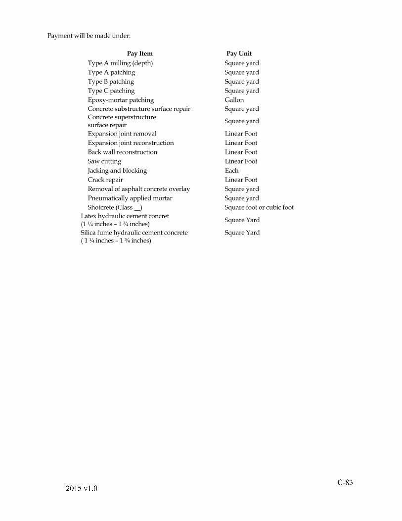
! " #$ % & ' ( & ) %
Payment will be made under:
Pay Item Pay Unit
Type A milling (depth) Square yard
Type A patching Square yard
Type B patching Square yard
Type C patching Square yard
Epoxy-mortar patching Gallon
Concrete substructure surface repair Square yard
Concrete superstructuresurface repair
Square yard
Expansion joint removal Linear Foot
Expansion joint reconstruction Linear Foot
Back wall reconstruction Linear Foot
Saw cutting Linear Foot
Jacking and blocking Each
Crack repair Linear Foot
Removal of asphalt concrete overlay Square yard
Pneumatically applied mortar Square yard
Shotcrete (Class ) Square foot or cubic foot
Latex hydraulic cement concret (1 ¼ inches � 1 ¾ inches)
Square Yard
Silica fume hydraulic cement concrete ( 1 ¼ inches � 1 ¾ inches)
Square Yard
! " # $ % & ' ( & ) %
Division V
Incidental Construction
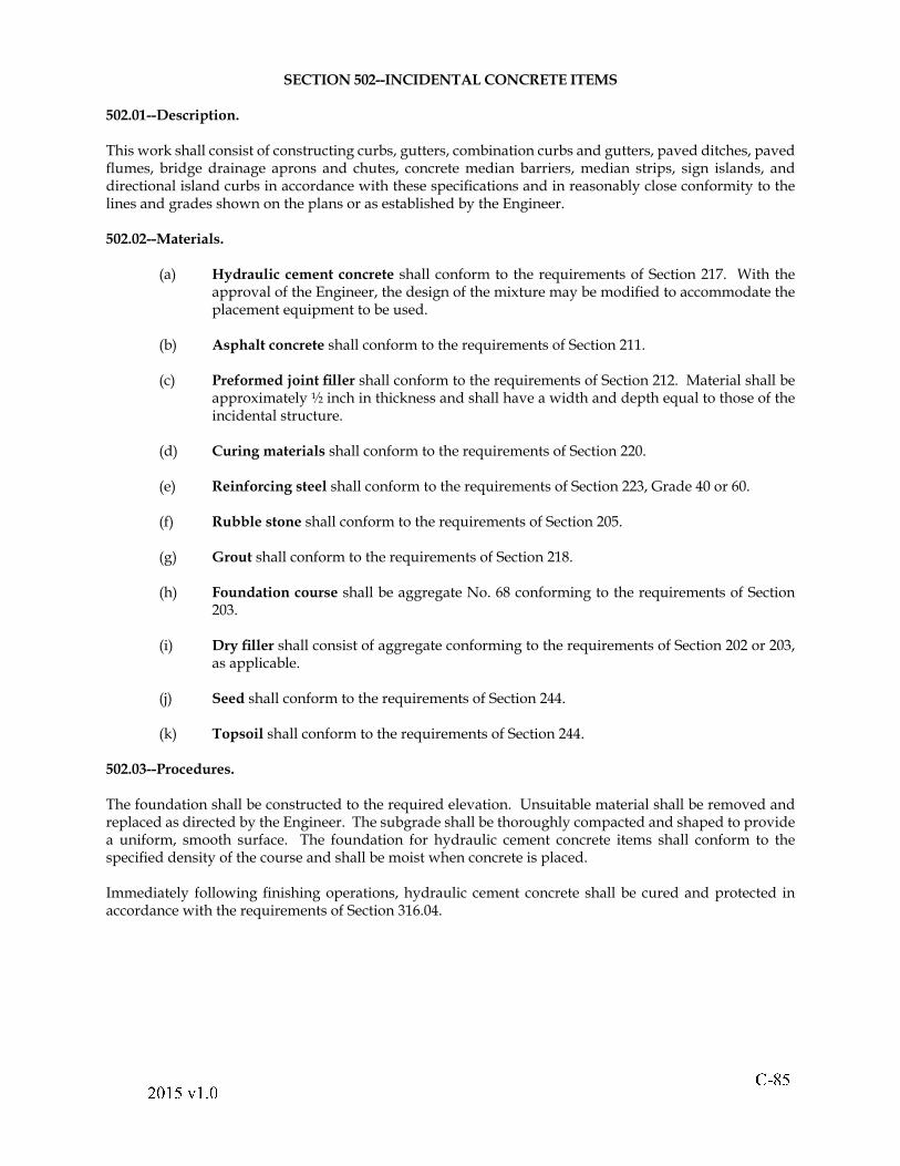
! " #$ % & # ' & ( %
SECTION 502--INCIDENTAL CONCRETE ITEMS
502.01--Description.
This work shall consist of constructing curbs, gutters, combination curbs and gutters, paved ditches, paved " umes, bridge drainage aprons and chutes, concrete median barriers, median strips, sign islands, and directional island curbs in accordance with these speci! cations and in reasonably close conformity to the lines and grades shown on the plans or as established by the Engineer.
502.02--Materials.
(a) Hydraulic cement concrete shall conform to the requirements of Section 217. With the approval of the Engineer, the design of the mixture may be modi! ed to accommodate the placement equipment to be used.
(b) Asphalt concrete shall conform to the requirements of Section 211.
(c) Preformed joint ! ller shall conform to the requirements of Section 212. Material shall be approximately ½ inch in thickness and shall have a width and depth equal to those of the incidental structure.
(d) Curing materials shall conform to the requirements of Section 220.
(e) Reinforcing steel shall conform to the requirements of Section 223, Grade 40 or 60.
(f) Rubble stone shall conform to the requirements of Section 205.
(g) Grout shall conform to the requirements of Section 218.
(h) Foundation course shall be aggregate No. 68 conforming to the requirements of Section 203.
(i) Dry ! ller shall consist of aggregate conforming to the requirements of Section 202 or 203, as applicable.
(j) Seed shall conform to the requirements of Section 244.
(k) Topsoil shall conform to the requirements of Section 244.
502.03--Procedures.
The foundation shall be constructed to the required elevation. Unsuitable material shall be removed and replaced as directed by the Engineer. The subgrade shall be thoroughly compacted and shaped to provide a uniform, smooth surface. The foundation for hydraulic cement concrete items shall conform to the speci! ed density of the course and shall be moist when concrete is placed.
Immediately following ! nishing operations, hydraulic cement concrete shall be cured and protected in accordance with the requirements of Section 316.04.
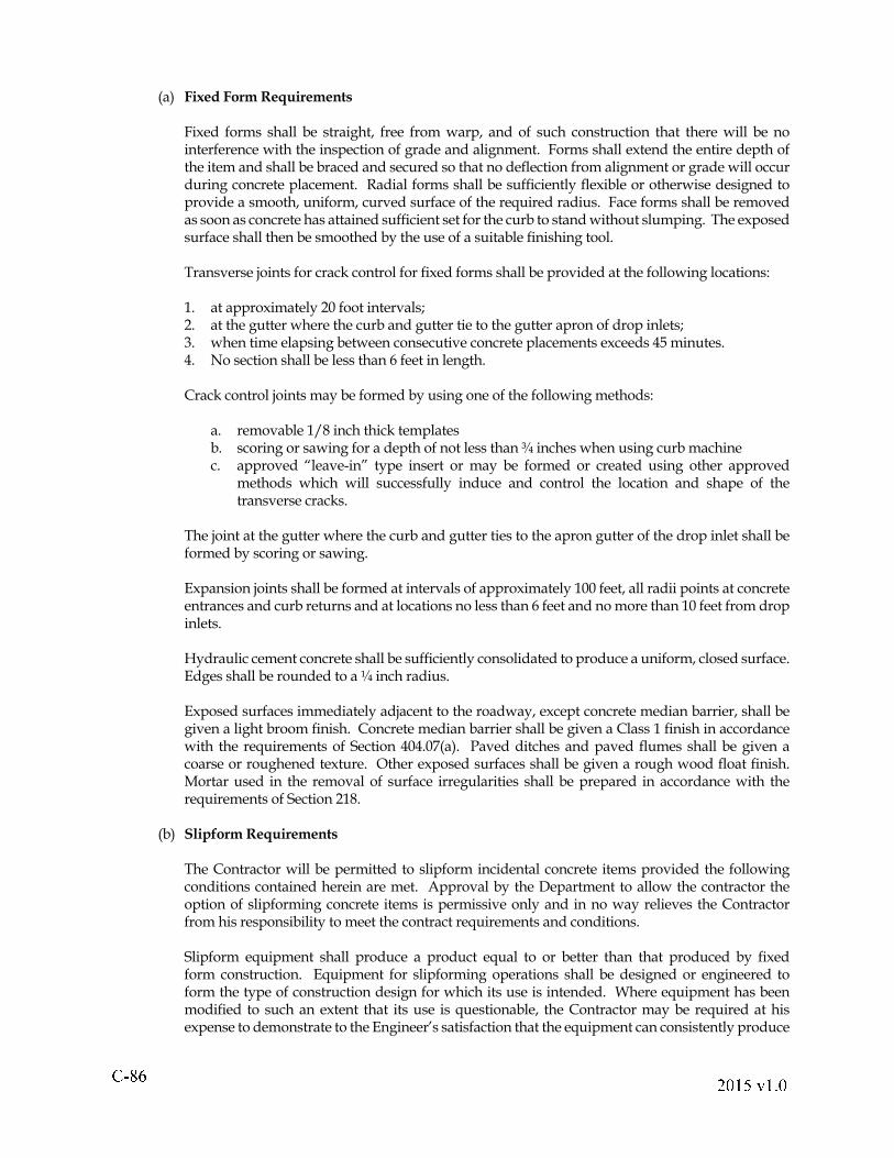
! " # $ % & ' ( & ) %
(a) Fixed Form Requirements
Fixed forms shall be straight, free from warp, and of such construction that there will be no interference with the inspection of grade and alignment. Forms shall extend the entire depth of the item and shall be braced and secured so that no de" ection from alignment or grade will occur during concrete placement. Radial forms shall be suf! ciently " exible or otherwise designed to provide a smooth, uniform, curved surface of the required radius. Face forms shall be removed as soon as concrete has attained suf! cient set for the curb to stand without slumping. The exposed surface shall then be smoothed by the use of a suitable ! nishing tool.
Transverse joints for crack control for ! xed forms shall be provided at the following locations:
1. at approximately 20 foot intervals; 2. at the gutter where the curb and gutter tie to the gutter apron of drop inlets; 3. when time elapsing between consecutive concrete placements exceeds 45 minutes. 4. No section shall be less than 6 feet in length.
Crack control joints may be formed by using one of the following methods:
a. removable 1/8 inch thick templatesb. scoring or sawing for a depth of not less than ¾ inches when using curb machinec. approved �leave-in� type insert or may be formed or created using other approved
methods which will successfully induce and control the location and shape of the transverse cracks.
The joint at the gutter where the curb and gutter ties to the apron gutter of the drop inlet shall be formed by scoring or sawing.
Expansion joints shall be formed at intervals of approximately 100 feet, all radii points at concrete entrances and curb returns and at locations no less than 6 feet and no more than 10 feet from drop inlets.
Hydraulic cement concrete shall be suf! ciently consolidated to produce a uniform, closed surface. Edges shall be rounded to a ¼ inch radius.
Exposed surfaces immediately adjacent to the roadway, except concrete median barrier, shall be given a light broom ! nish. Concrete median barrier shall be given a Class 1 ! nish in accordance with the requirements of Section 404.07(a). Paved ditches and paved " umes shall be given a coarse or roughened texture. Other exposed surfaces shall be given a rough wood " oat ! nish. Mortar used in the removal of surface irregularities shall be prepared in accordance with the requirements of Section 218.
(b) Slipform Requirements
The Contractor will be permitted to slipform incidental concrete items provided the following conditions contained herein are met. Approval by the Department to allow the contractor the option of slipforming concrete items is permissive only and in no way relieves the Contractor from his responsibility to meet the contract requirements and conditions.
Slipform equipment shall produce a product equal to or better than that produced by ! xed form construction. Equipment for slipforming operations shall be designed or engineered to form the type of construction design for which its use is intended. Where equipment has been modi! ed to such an extent that its use is questionable, the Contractor may be required at his expense to demonstrate to the Engineer�s satisfaction that the equipment can consistently produce
! " #$ % & ' ( & ) %
the desired type of construction. The slipform equipment shall be self-propelled and shall be equipped to consolidate, form, extrude, and ! nish the freshly placed concrete is such a manner that a minimum of hand ! nishing is required to produce a dense, consolidated, homogenous product. Slipform equipment shall be controlled to line and grade by automatic sensing, guidance and control devices such that the machine automatically senses and follows taut guidelines or other stable reference, performing any necessary corrective action to ensure the correct grade and alignment is achieved. The Contractor shall ensure the slipform operation is planned to result in the full cross section and grade of the desired design at the beginning and end of the placement. Slipform equipment shall operate with a continuous forward movement. The Contractor shall plan and stage the work to eliminate the need for the sllpform machine to be stopped during placement operations. If for any reason it is absolutely necessary to stop the forward progress of the machine; operation of the vibrating and tamping elements shall be stopped immediately. Equipment used for slipforming shall conform to the general requirements of Section 108.07. If the results of the slipform operation are not satisfactory to the Engineer in accordance with the requirements stated herein, the continued use of the equipment will not be permitted.
Concrete for use in slipform operations may be manufactured with a slump as low as zero (�0�). The top of the slump range shall conform to the class of concrete speci! ed on the plans or special provisions in accordance with Section 217. The concrete shall have properties that consistently maintain workability and the cross section, line, and grade of the proposed product. Concrete shall be ! nished to a light broom ! nish. If water is held back to maintain the desired slump, it may be added in increments provided the maximum water per cubic yard has not been exceeded and a minimum of 30 revolutions at mixing speed is used for complete mixing.
Where reinforcing steel is incorporated into the proposed design, it shall be uncoated steel conforming to Section 223. Reinforcing steel shall be tied at 100 percent of the bar intersections and shall be suf! ciently strengthened with braces, additional reinforcement or chairs to make the reinforcement cage rigid so as to prevent any movement during concrete placement. If the reinforcing steel exhibits any movement during concrete placement using slipforming methods, the work shall be suspended until the reinforcing steel has been suf! ciently tied and stabilized to the satisfaction of the Engineer. The reinforcing steel shall be continuous from ! xed object to ! xed object. All reinforcing steel shall have the appropriate amount of concrete cover for the particular design with a tolerance of �0 + ½ inch; however, in no case shall the amount of cover be less than 1 ½ inches. Reinforcing steel inserted in the freshly placed concrete shall be inserted with the use of vibration to achieve adequate bond of the reinforcing steel. Where bonding is suspect, the Engineer may require pull out tests be performed by the Contractor at his expense. If such tests con! rm the presence of adequate bond, the Department will reimburse the Contractor the cost of such testing.
The maximum height of any extrusion shall be limited such that the alignment and cross sectional shape of the design is maintained within the construction tolerances. If the Contractor elects to use or is required to use multiple placements to achieve a particular design, the Contractor shall submit a plan outlining the details of each placement for approval by the Engineer prior to beginning placement operations. Where multiple placements are permitted for installation of a particular design, the separate placements shall be staged so that any horizontal joints incorporated in the phased construction shall be arranged in such a manner as to prevent water in! ltration in the ! nal design and water " owing through any longitudinal joint.
Where weep holes are part of the proposed median barrier design, the Contractor shall use 6 inch diameter underdrain pipe in lieu of weep holes. Underdrain pipe conforming to Section 232 shall be installed at the grade at the bottom of the footing and shall terminate in catch basins or drop inlets.
Where naturally occurring vertical contraction cracking occurs and where there exists a grade separation on each side of the barrier, the Contractor shall install a waterproo! ng membrane conforming to Section 213, spanning 1 ½ feet on each side of the contraction crack at the back surface of the higher grade side of the barrier to prevent water from passing through the barrier.
! " " # $ % & ' % ( $
Expansion joint material 1 ½ inches thick shall be installed adjacent to each ! xed object. Expansion material shall be placed against each ! xed object prior to placement of the slipformed concrete. Contraction joints will not be required with slipformed operations provided the reinforcing steel is continuous from ! xed object to ! xed object.
( c) Individual Item Requirements
1. Hydraulic Cement Concrete Curbs, Gutters, Combination Curbs and Gutters, Paved Ditches, and Paved Flumes: Where standard mountable curb or combination curb and gutter with mountable curb is speci! ed, adjacent curbs of standard entrance gutter and standard connection for streets shall be modi! ed to provide a mountable shape corresponding to the standard mountable shape.
Where integral curb is speci! ed, the curb shall be placed simultaneously with or immediately after placement of the slab. The time period between slab and curb placement shall be not more than 45 minutes except as hereinafter speci! ed. The surface of the slab on which the curb is to be placed shall be roughened, and the concrete shall be placed so as to secure a bond between the slab and curb.
When authorized by the Engineer, the Contractor may construct the integral curb by providing steel dowels 5/8 inches in diameter, 7 inches in length, to be embedded in the slab at 1 foot intervals. Dowels shall be placed so as to extend at least 2 inches into the curb. While the slab is still plastic, it shall be roughened to a depth of approximately ½ inch below the screeded surface for the full width of the curb.
Local irregularities in the face and top of curbs shall be not more than 3/8 inch in 10 feet. Vertical alignment shall be suf! ciently uniform and regular to ensure complete drainage.
Any curb, gutter or combination curb and gutter, except those on structures, may be placed by the slipform method provided the ! nished product is true to line, cross section and grade and the concrete is dense and has the required surface texture. The concrete shall be of such consistency that it will remain the desired shape or cross section of the design without support.
Where concrete curb and or curb and gutter is placed over existing pavement, it shall be anchored to the existing pavement either by placing steel dowels and reinforcing steel or by using an approved adhesive. Steel dowels shall be ! rmly mortared with 1:1 Portland cement and sand mortar in holes drilled in the pavement. If an adhesive is used, the surface of the pavement shall be thoroughly cleaned before the adhesive is applied. Adhesive shall be EP-4 epoxy resin, a two component system conforming to Section 243 of the Speci! cations. The pavement shall be cleaned either by blast cleaning or by wire brushing so that the prepared surface is free of dust, loose material, oil, or any other material that may prove deleterious to bonding.
The grade for the top of the extruded curb shall be indicated by an offset guideline set by the
Contractor from survey information supplied to the Department. The forming tube portion of the extrusion machine shall be readily adjustable vertically to accommodate, when necessary, a variable height of curb conforming to the predetermined curb grade line. A grade line gage or pointer shall be attached to the machine to monitor the elevation of the curb being placed against the established grade line so as to make corrective adjustment as necessary. In lieu of a grade line gage or pointer the extrusion machine may be operated on rails or forms set to produce the predetermined ! nished grade line for the curbing.
! " #$ % & ' ( & ) %
Concrete shall be continuously fed to the slipforming machine at a uniform rate. The machine shall be operated under suf! cient uniform restraint of forward motion so as to produce a well compacted homogenous mass of concrete free from surface pits larger than inch in diameter and requiring no further ! nishing other than light brushing with a broom. Finishing with a brush application of grout will not be permitted.
Expansion joints shall be constructed as speci! ed for ! xed formed curbing or shall be constructed by sawing through the curb section to its full depth. The width of the cut shall be such to allow the insertion of the joint ! ller with a snug ! t. If sawing is performed before the concrete has hardened, the adjacent portions of the curb shall be supported ! rmly with close ! tting shields. The operations of sawing and inserting the joint ! ller shall be completed before curing the concrete.
If sawing is performed after the concrete has hardened, the joint ! ller shall be mortared in place with heavy trowel pressure. After sawing is performed, all exposed portions of the curb in the vicinity of the joint shall be covered with another application of curing compound. At the conclusion of the curing period, the ! ller in each sawn joint shall be checked for tightness of ! t. Any loose ! ller shall be mortared in place again and cured.
Within 3 to 7 days, the Contractor shall back! ll curb, gutter and combination curb and gutter to the required elevation with approved material. Back! ll material shall be compacted with curbs and gutters remaining plumb.
2. Asphalt Concrete Curbs and Paved Ditches: The curb shall be placed on a clean dry surface. Immediately prior to placement of the asphalt mixture, a tack coat of asphalt shall be applied to the surface at a rate between 0.05 and 0.15 gallons per square yard of surface. Asphalt shall be prevented from spreading outside the area to be occupied by the curb.
Asphalt concrete curb shall be placed by a self-propelled automatic curb machine or a paver having curbing attachments to form a satisfactorily compacted curb of a uniform texture, shape, and density. The Engineer may permit construction of curbs by other means when short sections or sections with short radii are required. The resulting curbs shall conform in all respects to curbs produced by a curb machine.
Sealing or painting shall be performed only on curbs that are clean, dry, and cooled to ambient temperature.
Asphalt concrete paved ditches shall be placed and compacted so as to provide a smooth, uniform, and dense texture.
3. Grouted Rubble Gutter: Aggregate for the foundation course shall be spread on the subgrade to a depth of at least 4 inches.
Gutter stones shall be bedded in the foundation course perpendicular to the ! nished surface, " at side up, in straight rows, with the longest dimension perpendicular to the centerline of the gutter. Joints shall be broken in a satisfactory manner, and the width of interstices in the dry gutter shall be not more than 1 inch.
Stones shall be rammed until the surface is ! rm and conforms to the ! nished grade and cross section. Joints shall then be ! lled with dry ! ller to within 4 inches of the top of stones, and the surface shall be rammed to ensure proper compaction of ! ller. After irregularities have been corrected, cement grout shall be poured and broomed into joints and over stones. Additional grout shall be applied and brooming shall be continued until grout remains " ush with the top of stones.
! " # $ # % & ' % ( #
4. Concrete Median Barriers: Concrete median barriers shall be constructed in accordance with the requirements speci! ed herein and in Sections 512, 404, and 410.
Concrete median barriers shall be constructed within an allowable tolerance of ±1/2 inch for overall depth and overall width, ±1/4 inch for the width of the upper portion of the barrier, and ±1/4 inch per 10 feet for horizontal alignment.
After the speci! ed curing time has elapsed, concrete median barriers for roadways shall be back! lled to the required elevation with approved material. Material shall be thoroughly tamped in layers not more than 6 inches in depth before compaction. Delineators shall be installed on median barriers in accordance with the requirements of Section 702.03.
502.04--Measurement and Payment.
Standard concrete curbs, radial curbs, standard combination curb and gutter, radial combination curb and gutter, and asphalt concrete curbs will be measured in linear feet along the face of the curb, complete-in-place, and will be paid for at the contract unit price per linear foot. The price shall include modifying curbs for standard entrance gutters, standard street connection pavement, and standard median strips. Where the curb or curb and gutter is adjacent to drop inlets, the contract unit price for the drop inlets shall include that part of the curb or curb and gutter within the limits of the structure.
Where there is no excavation within the limits of the curb, gutter, combination curb and gutter, or median barrier other than that necessary for its construction, the contract unit price shall include excavating, back! lling, compacting, and disposing of surplus and unsuitable material. Where excavation is necessary for the roadway, the part within the limits of the curb, gutter, combination curb and gutter, or median barrier section will be paid for as regular excavation in accordance with the requirements of Section 303.06.
Standard, radial, entrance, and grouted rubble gutters; paved ditches; paved " umes; street connection pavement; and bridge drainage aprons and chutes will be measured in square yards of surface area, complete-in-place, and will be paid for at the contract unit price per square yard. The price for grouted rubble gutter shall include rubble stone, grout, foundation course, and ! ller. When pipe drain ditch liner is substituted for standard paved ditch at the Contractor�s option, payment will be made at the contract unit price for the standard paved ditch speci! ed. When pipe drain ditch liner is speci! ed on the plans, payment will be made at the contract unit price per linear foot, complete-in-place.
The cost of excavation below the ! nished grade or below the slope surface of cut or ! ll sections that is necessary for installing and back! lling paved ditches and " umes shall be included in the contract unit price for the paved ditch or " ume. Undercut excavation below the neat lines of paved ditches in cut sections, including replacement back! ll for undercut excavation and excavation above the upper lateral limits of paved ditches and paved " umes that are outside the normal plan earthwork limits, will be measured and paid for in accordance with the requirements of Section 303.06.
Ditch Flume Connector will be measured in units of each, complete in place, and will be paid for at the contract unit price per each. This price shall include excavation when required, dowels, welded wire fabric, reinforcing steel, anchor lugs, curtain walls and concrete.
Cattle guards will be measured in units of each, complete-in-place, and will be paid for at the contract unit price per each.
Energy dissipators will be measured in units of each, complete-in-place, and will be paid for at the contract unit price per each.
! " #$ % # & ' # ( %
Median barriers will be measured in linear feet along the centerline of barriers complete in place and will be paid for at the contract unit price per linear foot. Unless otherwise speci! ed, this price shall include furnishing and placing delineators, aggregate, excavation, back! ll, weep hole covering, concrete cap, dowels and joint sealer.
Curb-cut ramps will not be measured for separate payment but will be measured in the units speci! ed for their components.
Median strips will be measured in linear feet as speci! ed and will be paid for at the contract unit price per square yard or linear foot.
Sign islands will be measured in units of each or square yards, complete-in-place, exclusive of posts and signs, and will be paid for at the contract unit price per each or per square yard.
Directional island curbs will be measured in linear feet along the face of the curb and will be paid for at the contract unit price per linear foot.
Embankment material between curb lines will be measured and paid for in accordance with the requirements of Section 303.06 except as speci! ed below.
When there is no excavation or construction other than that necessary for constructing median strips, sign islands, or directional island curbs, the contract unit price shall include excavating, removing existing pavement, disposing of surplus and unsuitable material, back! lling, and compacting. When excavation or demolition of pavement is necessary for the adjoining roadway, that portion within the limits of the median strip, sign island, or directional island curb will be paid for as regular excavation or demolition of pavement in accordance with the requirements of Sections 303.06 and 508.03, respectively.
These prices shall include applying topsoil and seed.
Payment will be made under:
Pay Item Pay Unit Curb (Type and standard) Linear Foot
Combination curb and gutter (Type and standard)
Linear Foot
Gutter (Type and standard) Square yard
Paved ditch (Standard) Square yard
Pipe drain ditch liner (Standard) Linear Foot
Paved " ume (Standard) Square yard
Energy dissipator (Standard) Each
Entrance gutter (Standard) Square yard
Street connection pavement (Standard) Square yard
Median barrier (Standard) Linear Foot Bridge drainage apron and chute
(Standard)Square yard
Median strip (Standard width) Square Yard or Linear Foot
Sign island (Standard) Each or Linear Foot
Directional island curb (Standard) Linear Foot
Cattle guard (Standard) Each
Ditch " ume connector (Standard) Each
! " # # $ % & ' % ( $
SECTION 509--PATCHING HYDRAULIC CEMENT CONCRETE PAVEMENT
509.01--Description.
This work shall consist of removing designated areas of defective hydraulic cement concrete pavement and unstable subbase material, replacing subbase material where required, and replacing pavement with high-early-strength hydraulic cement concrete in accordance with these speci! cations and in reasonably close conformity to the original lines and grades or those established by the Engineer.
509.02--Materials.
(a) Hydraulic cement concrete shall conform to the requirements of Section 217 for Class A3 paving concrete except that the compressive strength shall be at least 3,000 psi within 24 hours. The accelerated strength gain shall be achieved by the use of 800 ± 50 pounds per cubic yard of Type III cement conforming to the requirements of AASHTO M-85 and approved air-entraining, accelerating, and water-reducing admixtures conforming to the requirements of Section 215. If calcium chloride is permitted as an accelerating admixture, it shall be limited to 2 percent by mass. The air content shall be 6 ± 2 percent. The water/cement ratio shall be not more than 0.42 by weight.
The Contractor shall prepare a suf! cient number of trial batches in the presence of the Engineer to verify the strength and workability of the mixture design when required. The continued adequacy of the mixture design and minimum compressive strength will be veri! ed monthly by the Engineer.
(b) Asphalt concrete shall conform to the requirements of Section 211 except that material may be accepted by certi! cation and visually inspected at the job site.
(c) Subbase material shall conform to the requirements of Section 208.
(d) Preformed asphalt joint ! ller and joint sealer shall conform to the requirements of Section 212.
(e) Curing material shall conform to the requirements of Section 220.
(f) Reinforcing steel shall conform to the requirements of Section 223.
509.03--Procedures.
Where the existing joint dowel assembly is to be removed, existing concrete shall be saw cut and removed at least 1 foot on each side of transverse joints. Undisturbed portions of pavement adjacent to the area to be patched shall be left with straight, vertical sides. In areas from which concrete has been removed, the subbase shall be dressed, brought to grade, and mechanically compacted. Dowels and assemblies shall be removed and disposed of off the project.
Saw cuts shall not extend into adjacent concrete pavement except when repairs are to be extended at that location. Saw cuts shall be straight, neat, vertical, and parallel or perpendicular to the center line as required.
Unsuitable subbase shall be removed, disposed of, and replaced in accordance with the requirements of Section 307 or 308, whichever is applicable. Where soil cement subbase is present and sound, excavation below the top of the soil cement line and under adjacent slabs will not be required.
! " #$ % & ' ( & ) %
Preformed asphalt joint ! ller shall be installed in accordance with the requirements of Section 316.04(g)2.
Joint material and reinforcing steel shall be placed in accordance with the following:
1. Patches less than 10 feet in length: Preformed asphalt joint ! ller shall be placed " ush against the run-off side of the adjacent pavement.
2. Patches greater than 10 feet in length: Preformed asphalt joint ! ller shall be placed " ush against sides of the adjacent pavement.
3. Patches 20 feet in length or greater: Patches shall conform to the requirements of the applicable reinforced concrete pavement standards.
4. Load transfer devices used in initial construction: Load transfer devices shall be left intact, straightened, and used for tying in the replaced slab or shall be replaced with an approved load transfer device.
5. Joints: Rounded or beveled transverse joints shall be provided adjacent to the undisturbed pavement to allow installation of sealant at a depth of at least ¼ inch but not more than ½ inch.
The excavated area shall be thoroughly cleaned and moistened before concrete is placed.
Full-depth forms shall be of suf! cient strength to support plastic concrete without deformation.
Existing pavement shall not be removed if removal will result in concrete being placed when the air temperature is below 55 oF. The concrete temperature at the time of placement shall be at least 70 oF but not more than 95 oF.
Concrete shall be placed on the subgrade and consolidated so that it ! lls the area of the patch. Concrete shall be ! nished in accordance with the requirements of Section 316.04(h) except that the ! nal surface shall have a texture similar to that of the adjoining pavement.
As soon as concrete is ! nished and prior to its initial set, the patch and existing pavement for a distance of 8 feet shall be tested by means of a 10-foot straightedge placed parallel to the center line of the road surface. Irregularities in the patch in excess of ¼ inch shall be corrected.
Immediately after it has been textured, concrete shall be covered with wet burlap and PE ! lm. An insulating blanket shall be placed over the PE ! lm whenever the air temperature is below 65 oF during the curing period. Curing shall continue until immediately before opening to traf! c but will not be required beyond 24 hours.
Transverse joints at pavement repair locations shall be cleaned and resealed in accordance with the requirements of Section 316.04(m).
Asphalt concrete shoulders that are damaged during repair operations shall be reconstructed within 24 hours after completion of a patch in accordance with the requirements of Section 315 with full-depth SM-2A asphalt concrete to match the ! nished grade. If traf! c is to be permitted on the patch prior to reconstruction of the shoulder, the shoulder shall be temporarily repaired to prevent any hazardous condition.
Traf! c shall be maintained in accordance with the requirements of Section 512 or as directed by the Engineer.

! " # $ % & ' ( & ) %
509.04--Measurement and Payment.
Patching hydraulic cement concrete pavement will be measured in square yards of pavement surface area, complete-in-place, and will be paid for at the contract unit price per square yard. This price shall include saw cutting pavement full depth; removing and disposing of existing concrete; preparing subgrade; furnishing and installing preformed asphalt joint ! ller; placing, ! nishing, and curing special design concrete; trial batches; cleaning and resealing joints; repairing shoulders; sealing joints; and reinforcing steel.
Payment will be made under:
Pay Item Pay Unit Patching hydraulic cement Square yard
concrete pavement