Embed Size (px)
Citation preview
Adrian Rettig, [email protected] Martin Lagler, [email protected] Thomas Lamare, [email protected] Shuai Li, [email protected] Varnabhye Mahadea, [email protected] Sean McCallion, [email protected] Julia Chernushevich, [email protected]
Application of Organic Rankine Cycles (ORC)
A. Rettig1, M. Lagler2, T. Lamare3, S. Li4, V. Mahadea5, S. McCallion6, J. Chernushevich7
1 ZHAW Institute of Energy Systems and Fluid Engineering, Winterthur, Switzerland 2 Bühler AG, Application Technology Department, Uzwil, Switzerland
3 Holcim Group Support Ltd, Holderbank, Switzerland 4 Australian National University, Canberra, Australia
5 Sofap Ltd., Port Luis, Mauritius 6,7 University of Waterloo, Waterloo, Canada
Abstract: Organic Rankine Cycle (ORC) is a technology that can convert thermal energy at relative low temperatures in the range of 80 to 350 °C to electricity. This opens up the possibility to exploit low-grade heat that otherwise would be wasted. It can play an important role to improve the energy efficiency of new or existing energy-intensive applications. The aim of this project is to estimate the potential of new ORC applications. First of all, a short introduction to ORC technology is given. Existing ORC applications are statistically evaluated, which gives an overview of the present ORC business in terms of number and types of applications as well as applied power ranges. The estimation of the heat potential serves as a base e. g. for identifying and evaluating industrial processes with waste heat suitable for ORC applications. Depending on the industrial process the waste energy is rejected at different temperatures, which makes the optimal choice of the working fluid of great importance. Therefore a few aspects of the working fluid selection procedure are presented. Finally, the economical attractiveness of ORC systems is assessed taking into account factors such as ORC module sizes and country specific electricity prices, incentives, tax breaks etc.
ORC is a very wide field that allows us to address only a few facets. This paper is meant more as a mid-term than final report since the project is still in progress, i. e. not all of the objectives mentioned above have been accomplished yet.
Keywords: Organic Rankine Cycle, ORC, heat potential, working fluid, economy
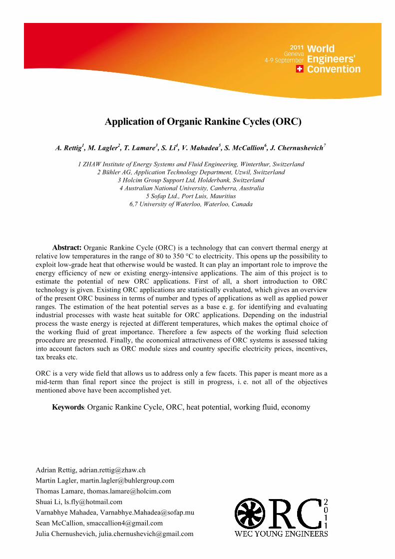
1. Introduction to Organic Rankine Cycle In chemical industries as well as in the production of food, paper, cement etc. a lot of thermal energy is needed. During these processes the heat carrier cools down to a temperature level where the residual heat can’t be used for the primary process. If the residual heat cannot be used for subsequent processes like drying granulates, the conversion of the waste heat to electricity may be an option. Organic Rankine Cycle (ORC) is a technology that can convert thermal energy at relative low temperatures in the range of 80 to 350 °C to electricity and can therefore play an important role to improve the energy efficiency of new or existing applications. Beside industrial waste heat alternative heat sources such as solar and geothermal energy as well as biomass can be applied. To better understand the Organic Rankine Cycle the process of a very simple conventional steam power plant (also called Clausius Rankine Cycle) is presented, see Figure 1. In a steam power plant the thermal energy is converted to electricity as water passes through a sequence of state changes. To implement these state changes the components like a turbine with generator, condenser, feed pump and boiler are needed.
Figure 1 Left, middle: T,s-Diagram and corresponding schematic of a simple conventional Rankine Cycle; right:
Carnot efficiency and electrical efficiency of a Rankine Cycle with various working fluids
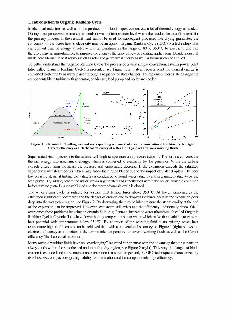
Superheated steam passes into the turbine with high temperature and pressure (state 1). The turbine converts the thermal energy into mechanical energy, which is converted to electricity by the generator. While the turbine extracts energy from the steam the pressure and temperature decrease. If the expansion exceeds the saturated vapor curve wet steam occurs which may erode the turbine blades due to the impact of water droplets. The cool low pressure steam at turbine exit (state 2) is condensed to liquid water (state 3) and pressurized (state 4) by the feed pump. By adding heat to the water, steam is generated and superheated within the boiler. Now the condition before turbine (state 1) is reestablished and the thermodynamic cycle is closed. The water steam cycle is suitable for turbine inlet temperatures above 350 °C. At lower temperatures the efficiency significantly decreases and the danger of erosion due to droplets increases because the expansion goes deep into the wet steam region, see Figure 2. By decreasing the turbine inlet pressure the steam quality at the end of the expansion can be improved. However, wet steam still exists and the efficiency additionally drops. ORC overcomes these problems by using an organic fluid, e. g. Pentane, instead of water (therefore it’s called Organic Rankine Cycle). Organic fluids have lower boiling temperatures than water which make them suitable to explore heat potential with temperatures below 350 °C. By adoption of the working fluid to an existing waste heat temperature higher efficiencies can be achieved than with a conventional steam cycle. Figure 1 (right) shows the electrical efficiency as a function of the turbine inlet temperature for several working fluids as well as the Carnot efficiency (the theoretical maximum). Many organic working fluids have an “overhanging” saturated vapor curve with the advantage that die expansion always ends within the superheated and therefore dry region, see Figure 2 (right). This way the danger of blade erosion is excluded and a low maintenance operation is assured. In general, the ORC technique is characterized by its robustness, compact design, high ability for automation and the comparatively high efficiency.
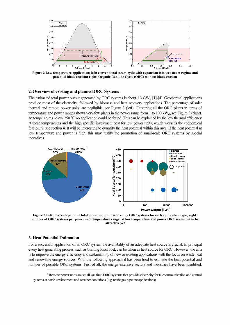
Figure 2 Low temperature application; left: conventional steam cycle with expansion into wet steam regime and
potential blade erosion; right: Organic Rankine Cycle (ORC) without blade erosion
2. Overview of existing and planned ORC Systems The estimated total power output generated by ORC systems is about 1.3 GWel [1]-[4]. Geothermal applications produce most of the electricity, followed by biomass and heat recovery applications. The percentage of solar thermal and remote power units1 are negligible, see Figure 3 (left). Clustering all the ORC plants in terms of temperature and power ranges shows very few plants in the power range form 1 to 100 kWel, see Figure 3 (right). At temperatures below 250 °C no application could be found. This can be explained by the low thermal efficiency at these temperatures and the high specific investment cost for low power units, which worsens the economical feasibility, see section 4. It will be interesting to quantify the heat potential within this area. If the heat potential at low temperature and power is high, this may justify the promotion of small-scale ORC systems by special incentives.
Figure 3 Left: Percentage of the total power output produced by ORC systems for each application type; right:
number of ORC systems per power and temperature range; at low temperature and power ORC seems not to be attractive yet
3. Heat Potential Estimation For a successful application of an ORC system the availability of an adequate heat source is crucial. In principal every heat generating process, such as burning fossil fuel, can be taken as heat source for ORC. However, the aim is to improve the energy efficiency and sustainability of new or existing applications with the focus on waste heat and renewable energy sources. With the following approach it has been tried to estimate the heat potential and number of possible ORC systems. First of all, the energy-intensive sectors and industries have been identified.
1 Remote power units are small gas fired ORC systems that provide electricity for telecommunication and control
systems at harsh environment and weather conditions (e.g. arctic gas pipeline applications)
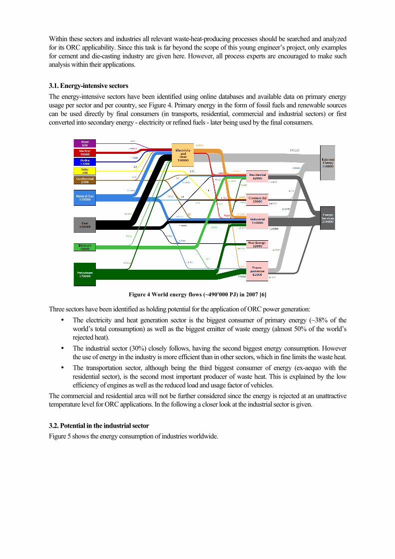
Within these sectors and industries all relevant waste-heat-producing processes should be searched and analyzed for its ORC applicability. Since this task is far beyond the scope of this young engineer’s project, only examples for cement and die-casting industry are given here. However, all process experts are encouraged to make such analysis within their applications. 3.1. Energy-intensive sectors The energy-intensive sectors have been identified using online databases and available data on primary energy usage per sector and per country, see Figure 4. Primary energy in the form of fossil fuels and renewable sources can be used directly by final consumers (in transports, residential, commercial and industrial sectors) or first converted into secondary energy - electricity or refined fuels - later being used by the final consumers.
Figure 4 World energy flows (~490'000 PJ) in 2007 [6]
Three sectors have been identified as holding potential for the application of ORC power generation: • The electricity and heat generation sector is the biggest consumer of primary energy (~38% of the
world’s total consumption) as well as the biggest emitter of waste energy (almost 50% of the world’s rejected heat).
• The industrial sector (30%) closely follows, having the second biggest energy consumption. However the use of energy in the industry is more efficient than in other sectors, which in fine limits the waste heat.
• The transportation sector, although being the third biggest consumer of energy (ex-aequo with the residential sector), is the second most important producer of waste heat. This is explained by the low efficiency of engines as well as the reduced load and usage factor of vehicles.
The commercial and residential area will not be further considered since the energy is rejected at an unattractive temperature level for ORC applications. In the following a closer look at the industrial sector is given. 3.2. Potential in the industrial sector Figure 5 shows the energy consumption of industries worldwide.
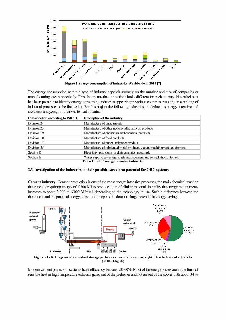
Figure 5 Energy consumption of industries Worldwide in 2010 [7]
The energy consumption within a type of industry depends strongly on the number and size of companies or manufacturing sites respectively. This also means that the statistic looks different for each country. Nevertheless it has been possible to identify energy-consuming industries appearing in various countries, resulting in a ranking of industrial processes to be focused at. For this project the following industries are defined as energy-intensive and are worth analyzing for their waste heat potential: Classification according to ISIC [1] Description of the industry Division 24 Manufacture of basic metals Division 23 Manufacture of other non-metallic mineral products Division 19 Manufacture of chemicals and chemical products Division 10 Manufacture of food products Division 17 Manufacture of paper and paper products Division 25 Manufacture of fabricated metal products, except machinery and equipment Section D Electricity, gas, steam and air conditioning supply Section E Water supply; sewerage, waste management and remediation activities
Table 1 List of energy-intensive industries
3.3. Investigation of the industries to their possible waste heat potential for ORC systems Cement industry: Cement production is one of the most energy intensive processes, the main chemical reaction theoretically requiring energy of 1’700 MJ to produce 1 ton of clinker material. In reality the energy requirements increases to about 3’000 to 6’000 MJ/t cli, depending on the technology in use. Such a difference between the theoretical and the practical energy consumption opens the door to a huge potential in energy savings.
Figure 6 Left: Diagram of a standard 4-stage preheater cement kiln system; right: Heat balance of a dry kiln
(3200 kJ/kg cli)
Modern cement plants kiln systems have efficiency between 50-60%. Most of the energy losses are in the form of sensible heat in high temperature exhausts gases out of the preheater and hot air out of the cooler with about 34 %
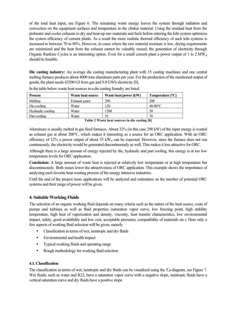
of the total heat input, see Figure 6. The remaining waste energy leaves the system through radiation and convection on the equipment surfaces and temperature in the clinker material. Using the residual heat from the preheater and cooler exhausts to dry and heat-up raw materials and fuels before entering the kiln system optimizes the system efficiency of cement plants. As a result the more realistic thermal efficiency of such kiln systems is increased to between 70 to 80%. However, in cases where the raw material moisture is low, drying requirements are minimized and the heat from the exhaust cannot be valuably reused, the generation of electricity through Organic Rankine Cycles is an interesting option. Even for a small cement plant a power output of 1 to 2 MWel should be feasible. Die casting industry: An average die casting manufacturing plant with 15 casting machines and one central melting furnace produces about 4000 tons aluminum parts per year. For the production of the mentioned output of goods, the plant needs 43200 GJ from gas and 9.8 GWh electricity [8]. In the table below waste heat sources in a die casting foundry are listed. Process Waste heat source Waste heat power [kW] Temperature [°C] Melting Exhaust gases 290 200 Die cooling Water 120 40-80°C Hydraulic cooling Water 1200 50 Part cooling Water 55 70
Table 2 Waste heat sources in die casting [8]
Aluminum is usually melted in gas fired furnaces. About 32% (in this case 290 kW) of the input energy is wasted as exhaust gas at about 200°C, which makes it interesting as a source for an ORC application. With an ORC efficiency of 12% a power output of about 35 kWel can be expected. However, since the furnace does not run continuously, the electricity would be generated discontinuously as well. This makes it less attractive for ORC. Although there is a large amount of energy rejected by die, hydraulic and part cooling, this energy is at too low temperature levels for ORC application. Conclusion: A large amount of waste heat is rejected at relatively low temperature or at high temperature but discontinuously. Both issues lower the attractiveness of ORC application. This example shows the importance of analyzing each favorite heat-wasting process of the energy intensive industries. Until the end of the project more applications will be analyzed and estimation on the number of potential ORC systems and their range of power will be given. 4. Suitable Working Fluids The selection of an organic working fluid depends on many criteria such as the nature of the heat source, costs of pumps and turbines as well as fluid properties (saturation vapor curve, low freezing point, high stability temperature, high heat of vaporization and density, viscosity, heat transfer characteristics, low environmental impact, safety, good availability and low cost, acceptable pressures, compatibility of materials etc.). Here only a few aspects of working fluid selection will be given, namely
• Classification in terms of wet, isentropic and dry fluids • Environmental and health impact • Typical working fluids and operating range • Rough methodology for working fluid selection
4.1. Classification The classification in terms of wet, isentropic and dry fluids can be visualized using the T,s-diagram, see Figure 7. Wet fluids, such as water and R22, have a saturation vapor curve with a negative slope, isentropic fluids have a vertical saturation curve and dry fluids have a positive slope.
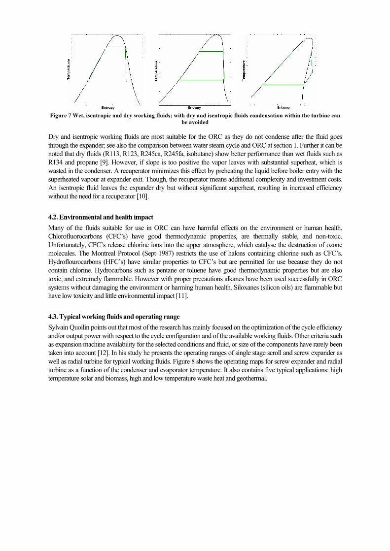
Figure 7 Wet, isentropic and dry working fluids; with dry and isentropic fluids condensation within the turbine can
be avoided
Dry and isentropic working fluids are most suitable for the ORC as they do not condense after the fluid goes through the expander; see also the comparison between water steam cycle and ORC at section 1. Further it can be noted that dry fluids (R113, R123, R245ca, R245fa, isobutane) show better performance than wet fluids such as R134 and propane [9]. However, if slope is too positive the vapor leaves with substantial superheat, which is wasted in the condenser. A recuperator minimizes this effect by preheating the liquid before boiler entry with the superheated vapour at expander exit. Though, the recuperator means additional complexity and investment costs. An isentropic fluid leaves the expander dry but without significant superheat, resulting in increased efficiency without the need for a recuperator [10]. 4.2. Environmental and health impact Many of the fluids suitable for use in ORC can have harmful effects on the environment or human health. Chlorofluorocarbons (CFC’s) have good thermodynamic properties, are thermally stable, and non-toxic. Unfortunately, CFC’s release chlorine ions into the upper atmosphere, which catalyse the destruction of ozone molecules. The Montreal Protocol (Sept 1987) restricts the use of halons containing chlorine such as CFC’s. Hydroflourocarbons (HFC’s) have similar properties to CFC’s but are permitted for use because they do not contain chlorine. Hydrocarbons such as pentane or toluene have good thermodynamic properties but are also toxic, and extremely flammable. However with proper precautions alkanes have been used successfully in ORC systems without damaging the environment or harming human health. Siloxanes (silicon oils) are flammable but have low toxicity and little environmental impact [11]. 4.3. Typical working fluids and operating range Sylvain Quoilin points out that most of the research has mainly focused on the optimization of the cycle efficiency and/or output power with respect to the cycle configuration and of the available working fluids. Other criteria such as expansion machine availability for the selected conditions and fluid, or size of the components have rarely been taken into account [12]. In his study he presents the operating ranges of single stage scroll and screw expander as well as radial turbine for typical working fluids. Figure 8 shows the operating maps for screw expander and radial turbine as a function of the condenser and evaporator temperature. It also contains five typical applications: high temperature solar and biomass, high and low temperature waste heat and geothermal.
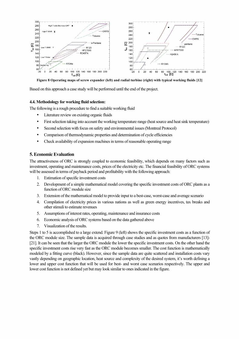
Figure 8 Operating maps of screw expander (left) and radial turbine (right) with typical working fluids [12]
Based on this approach a case study will be performed until the end of the project. 4.4. Methodology for working fluid selection: The following is a rough procedure to find a suitable working fluid
• Literature review on existing organic fluids • First selection taking into account the working temperature range (heat source and heat sink temperature) • Second selection with focus on safety and environmental issues (Montreal Protocol) • Comparison of thermodynamic properties and determination of cycle efficiencies • Check availability of expansion machines in terms of reasonable operating range
5. Economic Evaluation The attractiveness of ORC is strongly coupled to economic feasibility, which depends on many factors such as investment, operating and maintenance costs, prices of the electricity etc. The financial feasibility of ORC systems will be assessed in terms of payback period and profitability with the following approach:
1. Estimation of specific investment costs 2. Development of a simple mathematical model covering the specific investment costs of ORC plants as a
function of ORC module size 3. Extension of the mathematical model to provide input to a best-case, worst-case and average scenario 4. Compilation of electricity prices in various nations as well as green energy incentives, tax breaks and
other stimuli to estimate revenues 5. Assumptions of interest rates, operating, maintenance and insurance costs 6. Economic analysis of ORC systems based on the data gathered above 7. Visualization of the results.
Steps 1 to 5 is accomplished to a large extend. Figure 9 (left) shows the specific investment costs as a function of the ORC module size. The sample data is acquired through case studies and as quotes from manufacturers [13]-[21]. It can be seen that the larger the ORC module the lower the specific investment costs. On the other hand the specific investment costs rise very fast as the ORC module becomes smaller. The cost function is mathematically modeled by a fitting curve (black). However, since the sample data are quite scattered and installation costs vary vastly depending on geographic location, heat source and complexity of the desired system, it’s worth defining a lower and upper cost function that will be used for best- and worst case scenarios respectively. The upper and lower cost function is not defined yet but may look similar to ones indicated in the figure.
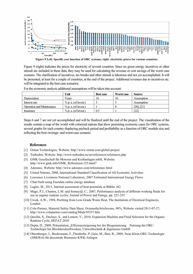
Figure 9 Left: Specific cost function of ORC systems; right: electricity prices for various countries
Figure 9 (right) indicates the prices for electricity of several countries. Since no green energy incentives or other stimuli are included in these data, they may be used for calculating the revenue or cost savings of the worst case scenario. The clarification of incentives, tax breaks and other stimuli is laborious and not yet accomplished. It will be presented, at least for a couple of countries, at the end of the project. Additional revenues due to incentives etc. will be integrated to the best case scenarios. For the economic analysis additional assumptions will be taken into account: Unit Best case Worst case Source Depreciation Years 10 10 Assumption Interest rate % p. a. (of invest.) 5 5 Assumption Operation and Maintenance % p. a. (of invest.) 1 8 [20], [21] Insurance % p. a. (of invest.) 0.5 1 [22] Steps 6 and 7 are not yet accomplished and will be finalized until the end of the project. The visualization of the results contain a map of the world with colorized nations that show promising economic cases for ORC systems, several graphs for each country displaying payback period and profitability as a function of ORC module size and reflecting the best-/average- and worst-case scenario.
References [1] Ormat Technologies, Website: http://www.ormat.com/global-project [2] Turboden, Website: http://www.turboden.eu/en/references/references.php [3] GMK Gesellschaft für Motoren und Kraftanlagen mbH, Website:
http://www.gmk.info/GMK_Referenzen.125.html? [4] Adoratec, Website: http://www.adoratec.com/referenznav.html [5] United Nations, 2008, International Standard Classification of All Economic Activities [6] Lawrence Livermore National Laboratory, 2007 Estimated International Energy Flows [7] Chart built using Enerdata online energy database [8] Lagler, M., 2011, Internal assessment of heat potentials at Bühler AG [9] Mago, P.J., Chamra, L.M. and Somayajl, C., 2007, Performance analysis of different working fluids for
use in organic rankine cycles, Journal of Power and Energy, pp. 221-255 [10] Crook, A.W., 1994, Profiting from Low-Grade Waste Heat, The Institution of Electrical Engineers,
London [11] Cole-Parmer, Material Safety Data Sheet, Octamethyltrisiloxane, 98%, Website visited 2011-07-27,
http://www.coleparmer.com/catalog/Msds/95557.htm [12] Quoilin, S., Declaye, S., and Lemort, V., 2010, Expansion Machine and Fluid Selection for the Organic
Rankine Cycle, HEFAT 2010 [13] Depta, D., 2009, Präsentation „Effizienzsteigerung bei der Biogasnutzung – Nutzung der ORC-
Technologie bei Blockheizkraftwerken, Umwelttechnik & Ingenieure GmbH [14] Obernberger, I., Biedermann, F.,Thonhofer, P.,Gaia, M., Bini, R., 2009, Neue Klein-ORC-Technologie
(200kWel) für dezentrale Biomasse-KWK-Anlagen

[15] Brélaz, D., Meystre, P., 2008, Réalisation d’une installation de micro cogénération pour la piscine de Mon
Repos, Services industriels, Sécurité publique et sports Lausanne [16] Priebe, K.-P., 2008, Effizienz kleiner ORC-Anlagen – Chancen und Grenzen der Nachverstromung
ungenutzter Wärme von BHKWs, Fachbeitrag von ADATURB [17] Case studies from Transpacific Energy, Website visited 2011-07-27,
http://www.transpacenergy.com/files/44487837.pdf [18] Personal talk to representative of ABB [19] Personal talk to representative of Infinity Turbine [20] Personal talk to representative of Pratt & Whitney Power Systems [21] Personal talk to representative of ORMAT [22] Personal talk to representative of AXA Winterthur insurance