Embed Size (px)
Citation preview
Application Note
R11AN0073EU0100 Rev.1.00 Page 1 of 57 May 5, 2017
Renesas Synergy™ Platform
Customizable Flashloader Solution for Synergy MCUs Introduction This application project describes how to integrate and use the Renesas Flashloader module to update the application software running on the Synergy microcontroller. The ability to update application software in the field without having to be physically present to open the device and access the debug port is critical to successfully pushing feature improvements and bug fixes to an embedded system. The Flashloader solution contains three separate application pieces:
• The user bootloader (referred to in remainder of this document as bootloader) runs on the Synergy microcontroller and performs the application update.
• The downloader also runs on the microcontroller but in a separate memory space from the user application code. The downloader receives the new application by communicating with an external host, device, or network. Once the application is validated, the bootloader performs the update.
• A software application running on a host such as a PC will facilitate the firmware update process.
The example Flashloader solution demonstrated in this application project leverages the Synergy Software Package (SSP) in addition to Express Logic’s ThreadX real-time operating system (RTOS) and the X-Ware USBX stack. The Flashloader application was developed within e2 Studio and IAR Embedded Workbench for Synergy using the SSP Flashloader Framework which is included in the associated project files.
Target Device The application project works with the Synergy MCU family. Examples are shown for the S7G2 Group on a Synergy Development Kit, DK-S7G2 Version 3.1. The appendices provide additional information about other microcontroller groups.
Minimum PC Recommendation • Microsoft® Windows® 7 • Intel® Core™ family processor running at 2.0 GHz or higher (or equivalent processor) • 8 GB memory • At least 2 GB of free space on hard disk or SSD • USB 2.0 • Connection to the Internet
Installed Software • Synergy Tool e2 studio 5.3.1.002 or IAR Embedded Workbench for Renesas Synergy version 7.71.1 • SSP v1.2.0 or later • Flashloader_pack1.2.0b1.exe • SPECIAL NOTE: Non-blocking example projects will also require SSP v1.2.0.b.1. The 1.2.0 r_crc module cannot
support multiple instances which is required for the non-blocking flashloader. • Python 2.7 for Windows • Python 2.7 modcrc • pyserial 3.2.1 library (https://github.com/pyserial/pyserial/releases) • r_fl_mot_convert.py and r_fl_serial_flashloader.py (included with project) • Microsoft Visual Studio (Free version) (only required if the Flashloader Utility GUI will be modified) • Microsoft .Net Framework 4.x
Note: If you do not have one of these software applications you should install it before continuing.
R11AN0073EU0100 Rev.1.00
May 5, 2017
Renesas Synergy™ Platform Customizable Flashloader Solution for Synergy MCUs
R11AN0073EU0100 Rev.1.00 Page 2 of 57 May 5, 2017
Recommended Reading • SSP User Manual introduction chapters • SSP Datasheet v1.2.0 or later • Synergy SSP Import Guide (R11AN0023EU0115)
Note: If you are not familiar with the above documents you should review them before continuing.
Provided Software Projects: • Bootloader • Downloader • Python Update Scripts • Flashloader PC Utility
Purpose This document will guide developers through integrating an example Flashloader solution into their project in addition to reviewing major components and software and how they can be customized and configured. Developers can use the example solution to understand Flashloader fundamentals and as a starting point for a production Flashloader solution. Every product will have slightly different requirements pertaining to the communication interface and how the application image is validated. The provided example is flexible and can be modified to fit nearly any application requirement.
Intended Audience The intended audience are users that understand the Synergy Platform’s fundamentals and are interested in developing an application that can be updated in the field through a Flashloader solution.
Prerequisites As the user of this application note, you are assumed to have some experience with the Renesas e2 studio ISDE and SSP. For example, before performing the procedure in this application note, you should follow the procedure in the board’s Quick Start Guide to build and run the ‘Blinky’ project.
By doing so, you will become familiar with e2 studio and the SSP, and ensure that the debug connection to your board is functioning properly.
In addition, you can use the SSP User Manual (available as part of the SSP download) to get complete information on the SSP architecture, modules, and starting development with SSP.
Renesas Synergy™ Platform Customizable Flashloader Solution for Synergy MCUs
R11AN0073EU0100 Rev.1.00 Page 3 of 57 May 5, 2017
Contents
1. Overview ................................................................................................................................. 4
2. Running the Custom Flashloader Solution Example ................................................................ 4 2.1 Preparation .............................................................................................................................................. 5 2.2 Setup 5 2.3 Running Flashloader ............................................................................................................................... 9
3. Bootloader Memory Layout .................................................................................................... 12
4. Downloader Memory Layout .................................................................................................. 13
5. Non-Blocking Bootloader Application Stack Configuration ..................................................... 14
6. Bootloader Linker Script ........................................................................................................ 20
7. Non-Blocking Bootloader Application Design and Implementation Overview ......................... 22
8. Blocking Bootloader Application Software Stack Configuration .............................................. 25
9. Blocking Bootloader Application Design and Implementation Overview ................................. 28
10. Non-Blocking Downloader Application Software Stack Overview ........................................... 30
11. Blocking Downloader Application Software Stack Overview .................................................. 33
12. Non-Blocking Downloader Application Design and Implementation Overview........................ 36
13. Downloader Linker Script ....................................................................................................... 38
14. Converting User Applications to BCH Files using the Python Converter Script ...................... 39 14.1 Convert User Application to BCH files manually ................................................................................... 41 14.1.1 Verify BCH image ................................................................................................................................ 41
15. Flashloader Utility Python Script ............................................................................................ 42
16. Flashloader Utility GUI ........................................................................................................... 44
17. Going Further ........................................................................................................................ 48
18. Troubleshooting ..................................................................................................................... 48
Appendix A Configuring the DK-S7G2 Development Kit for USB CDC ........................................ 49
Appendix B Configuring the DK-S7G2 Development Kit for UART .............................................. 50
Appendix C Installing USB CDC drivers in Windows 7/8 and Windows 10 .................................. 52
Renesas Synergy™ Platform Customizable Flashloader Solution for Synergy MCUs
R11AN0073EU0100 Rev.1.00 Page 4 of 57 May 5, 2017
1. Overview Flashloaders are the most common application component in embedded systems and probably the most neglected. The flashloader that we are discussing in this application project is software that a developer would develop and customize to run on their system. This flashloader should not be confused with the factory flashloader, which is an application built into the microcontrollers ROM designed to update the internal flash system. In some circumstances the factory flashloader is all that is required to update firmware in the field. However, in many cases developers will want to customize their firmware update process. This is where the flashloader that we will be discussing comes into play. There are many solutions for how a flashloader can be architected but the most flexible and scalable solution is to break the flashloader up into two primary components; the bootloader and the downloader.
The downloader is software within the developer’s application code that can detect that a new application is ready to be downloaded to the device through a communication interface. The downloader stores and validates the new application but it typically does not update the current application image. Instead, the downloader notifies the bootloader that there is an image available for updating. The downloader can be architected so that it behaves in a blocking or a non-blocking manner. A blocking downloader will prevent the primary application code for the product from executing while the new firmware is downloaded and updated. The non-blocking downloader will allow the application to execute normally while the new image is downloaded, usually to an external memory device. Once the downloader has stored the new image to either internal flash memory or external memory such as an SD card, the system can be restarted so that the bootloader can update the firmware.
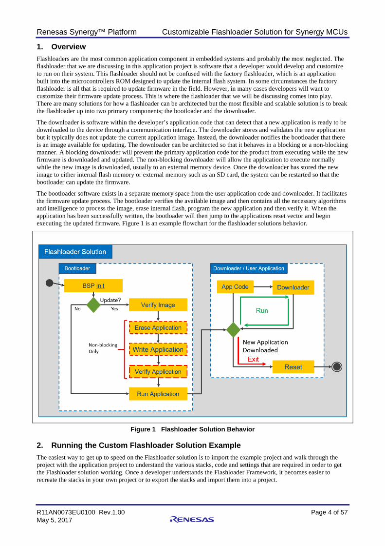
The bootloader software exists in a separate memory space from the user application code and downloader. It facilitates the firmware update process. The bootloader verifies the available image and then contains all the necessary algorithms and intelligence to process the image, erase internal flash, program the new application and then verify it. When the application has been successfully written, the bootloader will then jump to the applications reset vector and begin executing the updated firmware. Figure 1 is an example flowchart for the flashloader solutions behavior.
Figure 1 Flashloader Solution Behavior
2. Running the Custom Flashloader Solution Example The easiest way to get up to speed on the Flashloader solution is to import the example project and walk through the project with the application project to understand the various stacks, code and settings that are required in order to get the Flashloader solution working. Once a developer understands the Flashloader Framework, it becomes easier to recreate the stacks in your own project or to export the stacks and import them into a project.
Renesas Synergy™ Platform Customizable Flashloader Solution for Synergy MCUs
R11AN0073EU0100 Rev.1.00 Page 5 of 57 May 5, 2017
2.1 Preparation • Start setup by making sure that all the required applications listed at the beginning of the application project are
installed and downloading the Flashloader application project.
• Make sure that Flashloader_pack1.2.0b1.exe is installed so that you have the required SSP flashloader pack .
• If you are interested in the USB CDC flashloader, make sure that you examine the flashloader application package. Within the flashloader directory, there is a Windows USB driver that will allow the downloader application to show up as a standard serial communication port.
• Make sure that you download the Python 2.7 pyserial-3.3 library and install it. The library can be downloaded from https://pypi.python.org/pypi/pyserial/3.3. Alternatively, you can download pyserial using pip by running the following command from the python27 folder:
python -m pip install pyserial
• The python modcrc library also needs to be downloaded from https://pypi.python.org/pypi/crcmod/1.7. These libraries will allow the flashloader utility to communicate over a communication link and generate CRC’s for the communication packets.
• In order to proceed with running the example, the development kit will need to be configured based on the communication protocol and the development kit selected. Review the appendices for the development kit and communication protocol setup details. Walk through the appendix setup now.
2.2 Setup The following steps can then be used to setup the Flashloader:
1. Follow Synergy SSP Import Guide to import the desired flashloader solution. Example solutions include: USB CDC Non-blocking USB CDC Blocking UART Non-blocking UART Blocking
2. Each of these 4 examples includes two projects that must be imported into the workspace: The bootloader project The downloader project
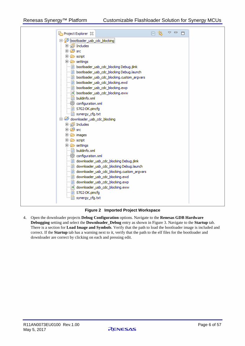
3. The workspace should appear similar to Figure 2.
Renesas Synergy™ Platform Customizable Flashloader Solution for Synergy MCUs
R11AN0073EU0100 Rev.1.00 Page 6 of 57 May 5, 2017
Figure 2 Imported Project Workspace
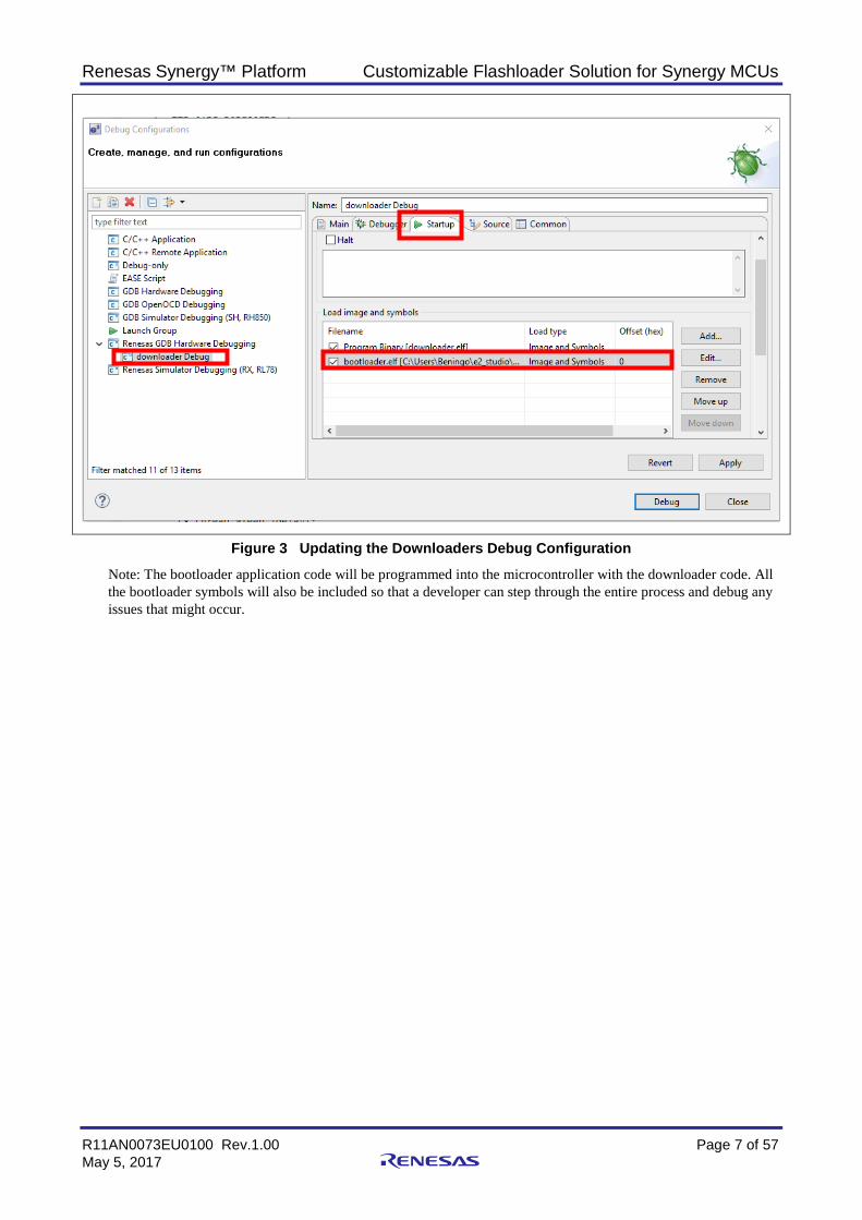
4. Open the downloader projects Debug Configuration options. Navigate to the Renesas GDB Hardware Debugging setting and select the Downloader_Debug entry as shown in Figure 3. Navigate to the Startup tab. There is a section for Load Image and Symbols. Verify that the path to load the bootloader image is included and correct. If the Startup tab has a warning next to it, verify that the path to the elf files for the bootloader and downloader are correct by clicking on each and pressing edit.
Renesas Synergy™ Platform Customizable Flashloader Solution for Synergy MCUs
R11AN0073EU0100 Rev.1.00 Page 7 of 57 May 5, 2017
Figure 3 Updating the Downloaders Debug Configuration
Note: The bootloader application code will be programmed into the microcontroller with the downloader code. All the bootloader symbols will also be included so that a developer can step through the entire process and debug any issues that might occur.
Renesas Synergy™ Platform Customizable Flashloader Solution for Synergy MCUs
R11AN0073EU0100 Rev.1.00 Page 8 of 57 May 5, 2017
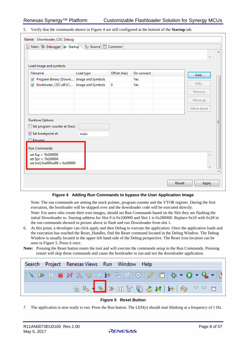
5. Verify that the commands shown in Figure 4 are still configured at the bottom of the Startup tab.
Figure 4 Adding Run Commands to bypass the User Application Image
Note: The run commands are setting the stack pointer, program counter and the VTOR register. During the first execution, the bootloader will be skipped over and the downloader code will be executed directly. Note: For users who create their own images, should set Run Commands based on the Slot they are flashing the initial Downloader to. Starting address for Slot 0 is 0x100000 and Slot 1 is 0x280000. Replace 0x10 with 0x28 in the run commands showed in picture above to flash and run Downloader from slot 1.
6. At this point, a developer can click apply and then Debug to execute the application. Once the application loads and the execution has reached the Reset_Handler, find the Reset command located in the Debug Window. The Debug Window is usually located in the upper left hand side of the Debug perspective. The Reset icon location can be seen in Figure 5. Press it once.
Note: Pressing the Reset button resets the tool and will execute the commands setup in the Run Commands. Pressing restart will skip those commands and cause the bootloader to run and not the downloader application.
Figure 5 Reset Button
7. The application is now ready to run. Press the Run button. The LED(s) should start blinking at a frequency of 1 Hz.
Renesas Synergy™ Platform Customizable Flashloader Solution for Synergy MCUs
R11AN0073EU0100 Rev.1.00 Page 9 of 57 May 5, 2017
2.3 Running Flashloader The flashloader solution is now executing. Now it is just a matter of communicating with the flashloader so that it can download a new application. Whether you are planning to use the Python script updater or the Flashloader Utility GUI, a developer will need to examine which communication port the downloader application will appear on. A developer needs to use a communication port whether they are using USB CDC or using UART through an FTDI USB to UART converter. The setup differences will be installing the correct driver.
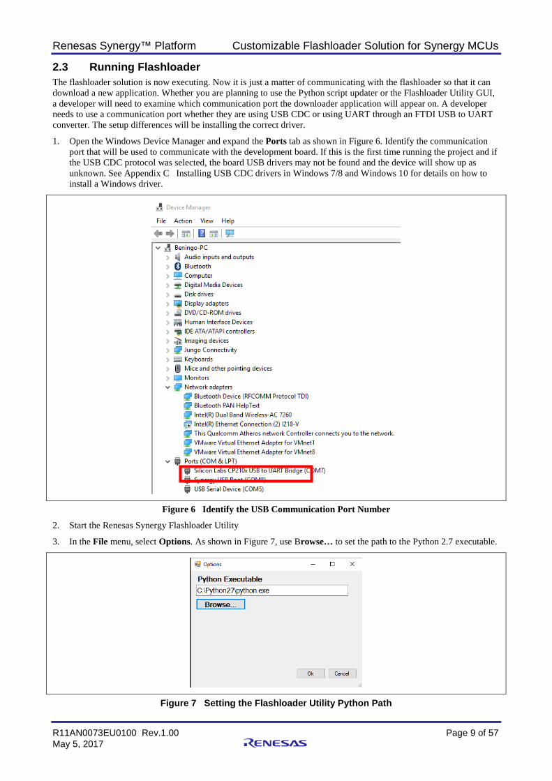
1. Open the Windows Device Manager and expand the Ports tab as shown in Figure 6. Identify the communication port that will be used to communicate with the development board. If this is the first time running the project and if the USB CDC protocol was selected, the board USB drivers may not be found and the device will show up as unknown. See Appendix C Installing USB CDC drivers in Windows 7/8 and Windows 10 for details on how to install a Windows driver.
Figure 6 Identify the USB Communication Port Number
2. Start the Renesas Synergy Flashloader Utility
3. In the File menu, select Options. As shown in Figure 7, use Browse… to set the path to the Python 2.7 executable.
Figure 7 Setting the Flashloader Utility Python Path
Renesas Synergy™ Platform Customizable Flashloader Solution for Synergy MCUs
R11AN0073EU0100 Rev.1.00 Page 10 of 57 May 5, 2017
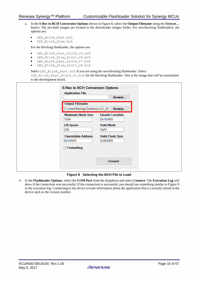
a. In the S-Rec to BCH Conversion Options shown in Figure 8, select the Output Filename using the Browse… button. The pre-built images are located in the downloader images folder. For non-blocking flashloaders, the options are:
• LED_Blink_Fast.bch • LED_Blink_Slow.bch
For the blocking flashloader, the options are:
• LED_Blink_Fast_Slot0_v5.bch • LED_Blink_Slow_Slot1_v6.bch • LED_Blink_Fast_Slot0_v7.bch • LED_Blink_Slow_Slot1_v8.bch
Select LED_Blink_Fast.bch if you are using the non-blocking flashloader. Select LED_Blink_Fast_Slot0_v5.bch for the blocking flashloader. This is the image that will be transmitted to the development board.
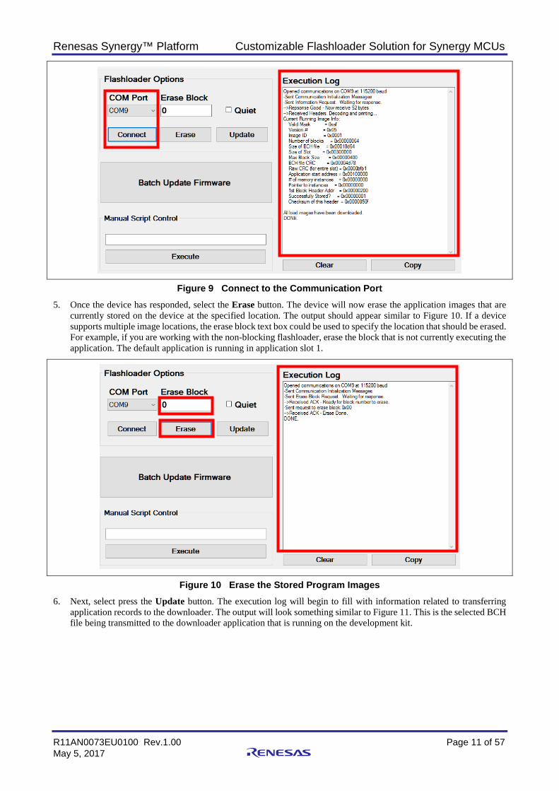
Figure 8 Selecting the BCH File to Load 4. In the Flashloader Options, select the COM Port from the dropdown and select Connect. The Execution Log will
show if the connection was successful. If the connection is successful, you should see something similar to Figure 9 in the execution log. Connecting to the device reveals information about the application that is currently stored in the device such as the version number.
Renesas Synergy™ Platform Customizable Flashloader Solution for Synergy MCUs
R11AN0073EU0100 Rev.1.00 Page 11 of 57 May 5, 2017
Figure 9 Connect to the Communication Port 5. Once the device has responded, select the Erase button. The device will now erase the application images that are
currently stored on the device at the specified location. The output should appear similar to Figure 10. If a device supports multiple image locations, the erase block text box could be used to specify the location that should be erased. For example, if you are working with the non-blocking flashloader, erase the block that is not currently executing the application. The default application is running in application slot 1.
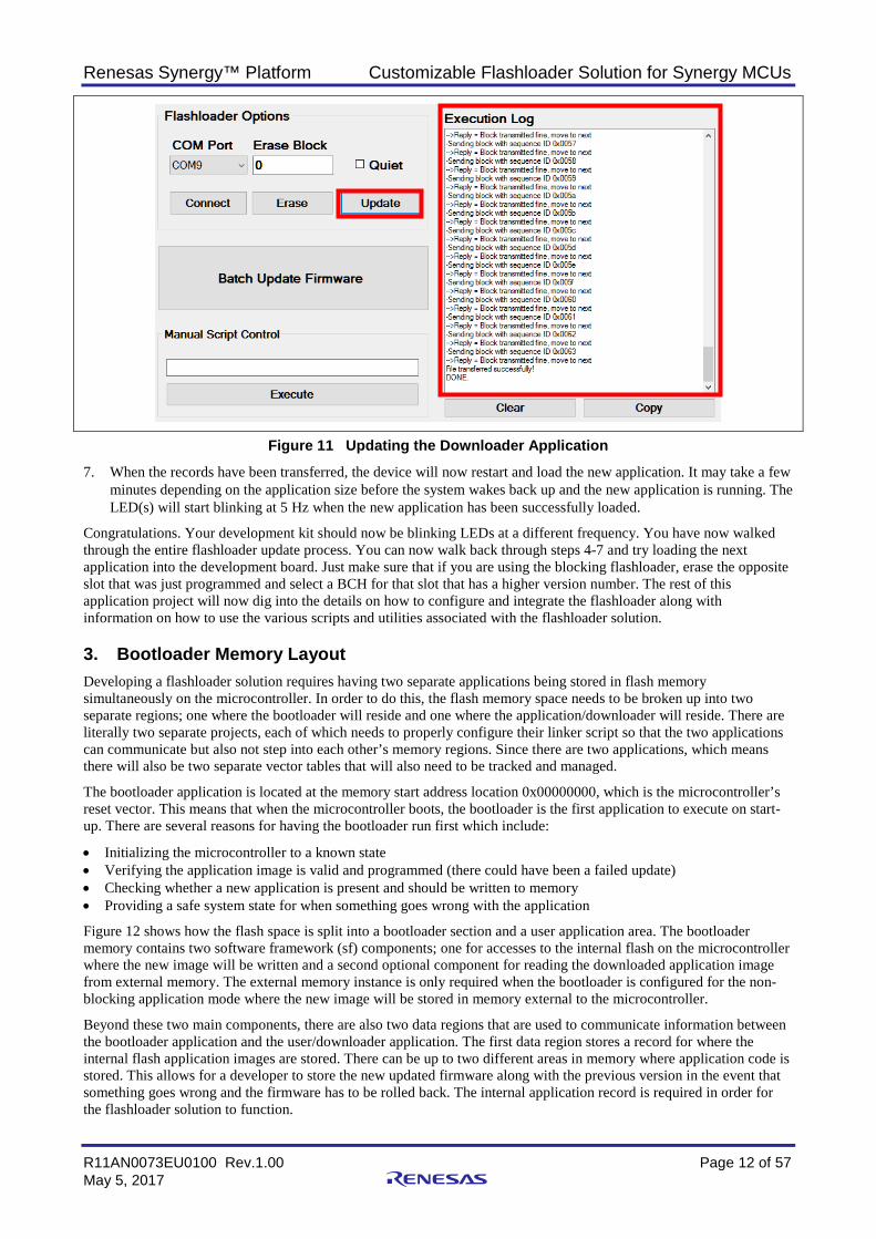
Figure 10 Erase the Stored Program Images 6. Next, select press the Update button. The execution log will begin to fill with information related to transferring
application records to the downloader. The output will look something similar to Figure 11. This is the selected BCH file being transmitted to the downloader application that is running on the development kit.
Renesas Synergy™ Platform Customizable Flashloader Solution for Synergy MCUs
R11AN0073EU0100 Rev.1.00 Page 12 of 57 May 5, 2017
Figure 11 Updating the Downloader Application
7. When the records have been transferred, the device will now restart and load the new application. It may take a few minutes depending on the application size before the system wakes back up and the new application is running. The LED(s) will start blinking at 5 Hz when the new application has been successfully loaded.
Congratulations. Your development kit should now be blinking LEDs at a different frequency. You have now walked through the entire flashloader update process. You can now walk back through steps 4-7 and try loading the next application into the development board. Just make sure that if you are using the blocking flashloader, erase the opposite slot that was just programmed and select a BCH for that slot that has a higher version number. The rest of this application project will now dig into the details on how to configure and integrate the flashloader along with information on how to use the various scripts and utilities associated with the flashloader solution.
3. Bootloader Memory Layout Developing a flashloader solution requires having two separate applications being stored in flash memory simultaneously on the microcontroller. In order to do this, the flash memory space needs to be broken up into two separate regions; one where the bootloader will reside and one where the application/downloader will reside. There are literally two separate projects, each of which needs to properly configure their linker script so that the two applications can communicate but also not step into each other’s memory regions. Since there are two applications, which means there will also be two separate vector tables that will also need to be tracked and managed.
The bootloader application is located at the memory start address location 0x00000000, which is the microcontroller’s reset vector. This means that when the microcontroller boots, the bootloader is the first application to execute on start-up. There are several reasons for having the bootloader run first which include:
• Initializing the microcontroller to a known state • Verifying the application image is valid and programmed (there could have been a failed update) • Checking whether a new application is present and should be written to memory • Providing a safe system state for when something goes wrong with the application
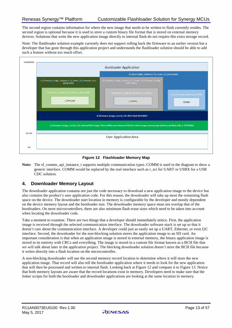
Figure 12 shows how the flash space is split into a bootloader section and a user application area. The bootloader memory contains two software framework (sf) components; one for accesses to the internal flash on the microcontroller where the new image will be written and a second optional component for reading the downloaded application image from external memory. The external memory instance is only required when the bootloader is configured for the non-blocking application mode where the new image will be stored in memory external to the microcontroller.
Beyond these two main components, there are also two data regions that are used to communicate information between the bootloader application and the user/downloader application. The first data region stores a record for where the internal flash application images are stored. There can be up to two different areas in memory where application code is stored. This allows for a developer to store the new updated firmware along with the previous version in the event that something goes wrong and the firmware has to be rolled back. The internal application record is required in order for the flashloader solution to function.
Renesas Synergy™ Platform Customizable Flashloader Solution for Synergy MCUs
R11AN0073EU0100 Rev.1.00 Page 13 of 57 May 5, 2017
The second region contains information for where the new image that needs to be written to flash currently resides. The second region is optional because it is used to store a custom binary file format that is stored on external memory devices. Solutions that write the new application image directly to internal flash do not require this extra storage record.
Note: The flashloader solution example currently does not support rolling back the firmware to an earlier version but a developer that has gone through this application project and understands the flashloader solution should be able to add such a feature without too much effort.
Figure 12 Flashloader Memory Map
Note: The sf_comms_api_instance_t supports multiple communication types. COMM is used in the diagram to show a generic interface. COMM would be replaced by the real interface such as r_sci for UART or USBX for a USB CDC solution.
4. Downloader Memory Layout The downloader application contains not just the code necessary to download a new application image to the device but also contains the product’s user application code. For this reason, the downloader will take up most the remaining flash space on the device. The downloader start location in memory is configurable by the developer and mostly dependent on the device memory layout and the bootloader size. The downloader memory space must not overlap that of the bootloaders. On most microcontrollers, there are also minimum flash erase sizes which need to be taken into account when locating the downloader code.
Take a moment to examine. There are two things that a developer should immediately notice. First, the application image is received through the selected communication interface. The downloader software stack is set up so that it doesn’t care about the communication interface. A developer could just as easily set up a UART, Ethernet, or even I2C interface. Second, the downloader for the non-blocking solution stores the application image to an SD card. An important consideration is that when an application image is stored in external memory, the binary application image is stored in its entirety with CRCs and everything. The image is stored in a custom file format known as a BCH file that we will talk about later in the application project. The blocking downloader solution doesn’t store the BCH file because it writes directly into a flash location on the microcontroller.
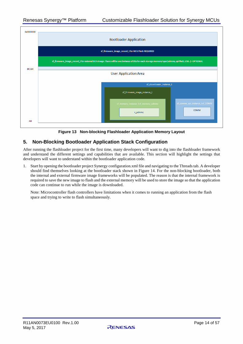
A non-blocking downloader will use the second memory record location to determine where it will store the new application image. That record will also tell the bootloader application where it needs to look for the new application that will then be processed and written to internal flash. Looking back at Figure 12 and compare it to Figure 13. Notice that both memory layouts are aware that the record locations exist in memory. Developers need to make sure that the linker scripts for both the bootloader and downloader applications are looking at the same location in memory.
Renesas Synergy™ Platform Customizable Flashloader Solution for Synergy MCUs
R11AN0073EU0100 Rev.1.00 Page 14 of 57 May 5, 2017
Figure 13 Non-blocking Flashloader Application Memory Layout
5. Non-Blocking Bootloader Application Stack Configuration After running the flashloader project for the first time, many developers will want to dig into the flashloader framework and understand the different settings and capabilities that are available. This section will highlight the settings that developers will want to understand within the bootloader application code.
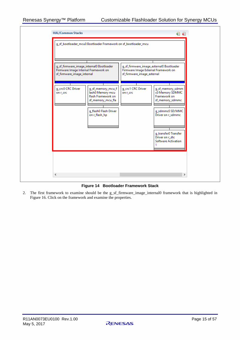
1. Start by opening the bootloader project Synergy configuration.xml file and navigating to the Threads tab. A developer should find themselves looking at the bootloader stack shown in Figure 14. For the non-blocking bootloader, both the internal and external firmware image frameworks will be populated. The reason is that the internal framework is required to save the new image to flash and the external memory will be used to store the image so that the application code can continue to run while the image is downloaded.
Note: Microcontroller flash controllers have limitations when it comes to running an application from the flash space and trying to write to flash simultaneously.
Renesas Synergy™ Platform Customizable Flashloader Solution for Synergy MCUs
R11AN0073EU0100 Rev.1.00 Page 15 of 57 May 5, 2017
Figure 14 Bootloader Framework Stack 2. The first framework to examine should be the g_sf_firmware_image_internal0 framework that is highlighted in
Figure 16. Click on the framework and examine the properties.
Renesas Synergy™ Platform Customizable Flashloader Solution for Synergy MCUs
R11AN0073EU0100 Rev.1.00 Page 16 of 57 May 5, 2017
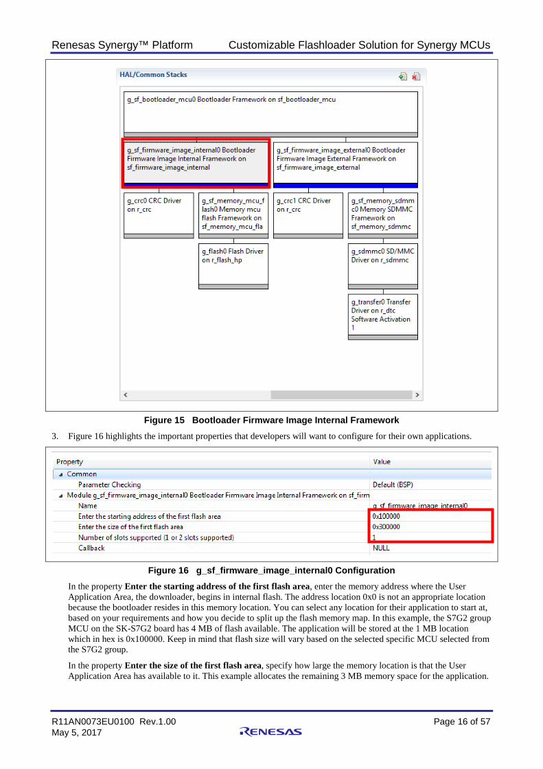
Figure 15 Bootloader Firmware Image Internal Framework 3. Figure 16 highlights the important properties that developers will want to configure for their own applications.
Figure 16 g_sf_firmware_image_internal0 Configuration In the property Enter the starting address of the first flash area, enter the memory address where the User Application Area, the downloader, begins in internal flash. The address location 0x0 is not an appropriate location because the bootloader resides in this memory location. You can select any location for their application to start at, based on your requirements and how you decide to split up the flash memory map. In this example, the S7G2 group MCU on the SK-S7G2 board has 4 MB of flash available. The application will be stored at the 1 MB location which in hex is 0x100000. Keep in mind that flash size will vary based on the selected specific MCU selected from the S7G2 group.
In the property Enter the size of the first flash area, specify how large the memory location is that the User Application Area has available to it. This example allocates the remaining 3 MB memory space for the application.
Renesas Synergy™ Platform Customizable Flashloader Solution for Synergy MCUs
R11AN0073EU0100 Rev.1.00 Page 17 of 57 May 5, 2017
In the property Number of slots supported determines whether the memory space specified will be used to store one single application image or whether it will be broken up into two application areas. The value 2 will split the flash area size in half and allow a developer to store multiple images on the internal flash. This can be used to keep a backup image in the event something goes wrong with a firmware update.
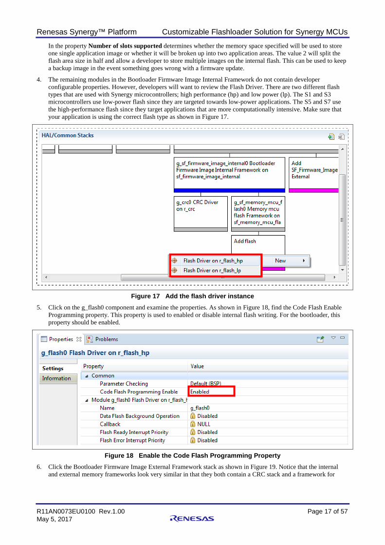
4. The remaining modules in the Bootloader Firmware Image Internal Framework do not contain developer configurable properties. However, developers will want to review the Flash Driver. There are two different flash types that are used with Synergy microcontrollers; high performance (hp) and low power (lp). The S1 and S3 microcontrollers use low-power flash since they are targeted towards low-power applications. The S5 and S7 use the high-performance flash since they target applications that are more computationally intensive. Make sure that your application is using the correct flash type as shown in Figure 17.
Figure 17 Add the flash driver instance 5. Click on the g_flash0 component and examine the properties. As shown in Figure 18, find the Code Flash Enable
Programming property. This property is used to enabled or disable internal flash writing. For the bootloader, this property should be enabled.
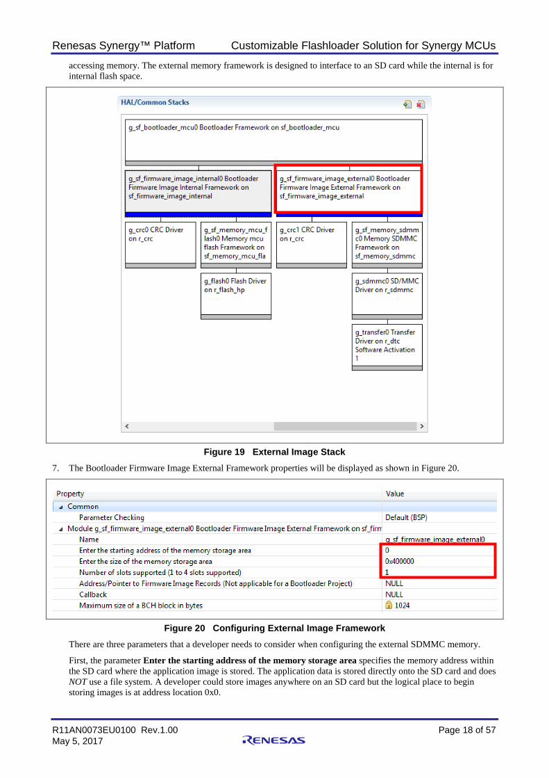
Figure 18 Enable the Code Flash Programming Property 6. Click the Bootloader Firmware Image External Framework stack as shown in Figure 19. Notice that the internal
and external memory frameworks look very similar in that they both contain a CRC stack and a framework for
Renesas Synergy™ Platform Customizable Flashloader Solution for Synergy MCUs
R11AN0073EU0100 Rev.1.00 Page 18 of 57 May 5, 2017
accessing memory. The external memory framework is designed to interface to an SD card while the internal is for internal flash space.
Figure 19 External Image Stack 7. The Bootloader Firmware Image External Framework properties will be displayed as shown in Figure 20.
Figure 20 Configuring External Image Framework There are three parameters that a developer needs to consider when configuring the external SDMMC memory.
First, the parameter Enter the starting address of the memory storage area specifies the memory address within the SD card where the application image is stored. The application data is stored directly onto the SD card and does NOT use a file system. A developer could store images anywhere on an SD card but the logical place to begin storing images is at address location 0x0.
Renesas Synergy™ Platform Customizable Flashloader Solution for Synergy MCUs
R11AN0073EU0100 Rev.1.00 Page 19 of 57 May 5, 2017
The parameter Enter the size of the memory storage area is the size on the SD card that will be used to store the BCH image. The developer should size this to be the maximum application size plus the BCH file overhead from CRCs. In this example, the microcontroller has 4 MB of flash available but only 3 MB is used for the user application. Sizing the memory storage location to the 4 MB provides sufficient overhead to store a 3 MB image plus the BCH file overhead.
Finally, since the updated images are being stored to an SD card first, multiple images can be stored to the card. For this example, the number of image slots is set to just one even though the bootloader framework supports storing up to four images on the external memory device.
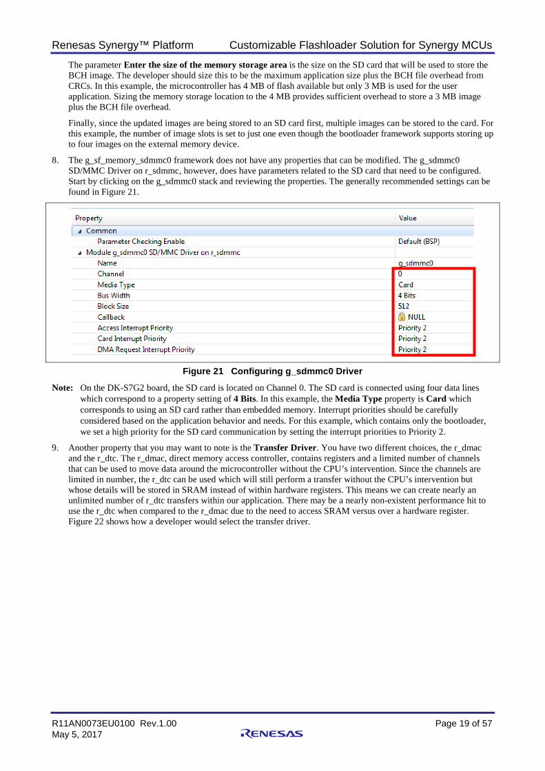
8. The g_sf_memory_sdmmc0 framework does not have any properties that can be modified. The g_sdmmc0 SD/MMC Driver on r_sdmmc, however, does have parameters related to the SD card that need to be configured. Start by clicking on the g_sdmmc0 stack and reviewing the properties. The generally recommended settings can be found in Figure 21.
Figure 21 Configuring g_sdmmc0 Driver
Note: On the DK-S7G2 board, the SD card is located on Channel 0. The SD card is connected using four data lines which correspond to a property setting of 4 Bits. In this example, the Media Type property is Card which corresponds to using an SD card rather than embedded memory. Interrupt priorities should be carefully considered based on the application behavior and needs. For this example, which contains only the bootloader, we set a high priority for the SD card communication by setting the interrupt priorities to Priority 2.
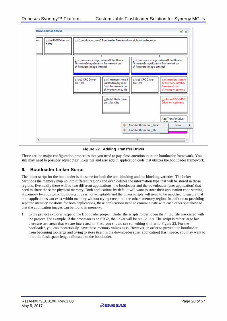
9. Another property that you may want to note is the Transfer Driver. You have two different choices, the r_dmac and the r_dtc. The r_dmac, direct memory access controller, contains registers and a limited number of channels that can be used to move data around the microcontroller without the CPU’s intervention. Since the channels are limited in number, the r_dtc can be used which will still perform a transfer without the CPU’s intervention but whose details will be stored in SRAM instead of within hardware registers. This means we can create nearly an unlimited number of r_dtc transfers within our application. There may be a nearly non-existent performance hit to use the r_dtc when compared to the r_dmac due to the need to access SRAM versus over a hardware register. Figure 22 shows how a developer would select the transfer driver.
Renesas Synergy™ Platform Customizable Flashloader Solution for Synergy MCUs
R11AN0073EU0100 Rev.1.00 Page 20 of 57 May 5, 2017
Figure 22 Adding Transfer Driver Those are the major configuration properties that you need to pay close attention to in the bootloader framework. You still may need to possibly adjust their linker file and also add in application code that utilizes the bootloader framework.
6. Bootloader Linker Script The linker script for the bootloader is the same for both the non-blocking and the blocking varieties. The linker partitions the memory map up into different regions and even defines the information type that will be stored in those regions. Eventually there will be two different applications, the bootloader and the downloader (user application) that need to share the same physical memory. Both applications by default will want to store their application code starting at memory location zero. Obviously, this is not acceptable and the linker scripts will need to be modified to ensure that both applications can exist within memory without trying creep into the others memory region. In addition to providing separate memory locations for both applications, these applications need to communicate with each other somehow so that the application images can be found in memory.
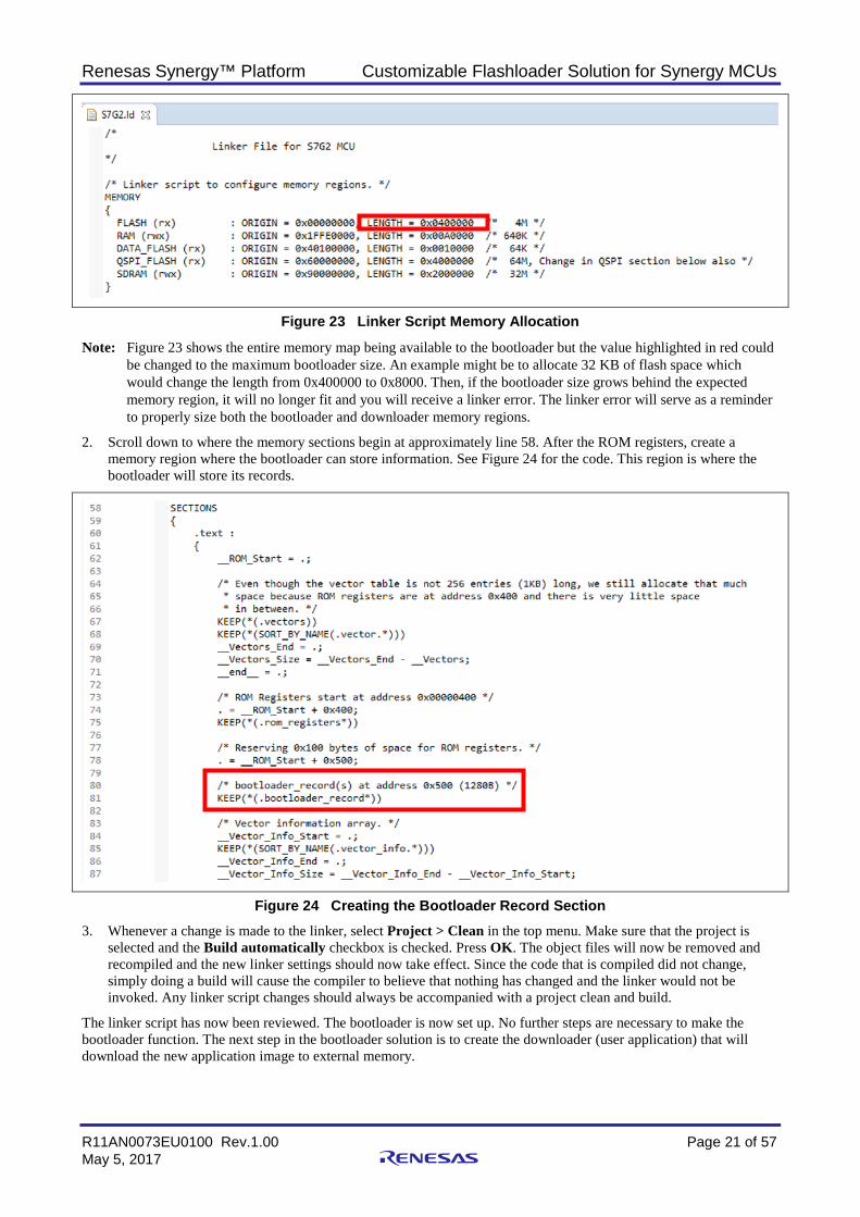
1. In the project explorer, expand the Bootloader project. Under the scripts folder, open the *.ld file associated with the project. For example, if the processor is an S7G2, the linker will be S7G2.ld. The script is rather large but there are two areas that we are interested in. First, you should see something similar to Figure 23. For the bootloader, you can theoretically leave these memory values as is. However, in order to prevent the bootloader from becoming too large and trying to store itself in the downloader (user application) flash space, you may want to limit the flash space length allocated to the bootloader.
Renesas Synergy™ Platform Customizable Flashloader Solution for Synergy MCUs
R11AN0073EU0100 Rev.1.00 Page 21 of 57 May 5, 2017
Figure 23 Linker Script Memory Allocation
Note: Figure 23 shows the entire memory map being available to the bootloader but the value highlighted in red could be changed to the maximum bootloader size. An example might be to allocate 32 KB of flash space which would change the length from 0x400000 to 0x8000. Then, if the bootloader size grows behind the expected memory region, it will no longer fit and you will receive a linker error. The linker error will serve as a reminder to properly size both the bootloader and downloader memory regions.
2. Scroll down to where the memory sections begin at approximately line 58. After the ROM registers, create a memory region where the bootloader can store information. See Figure 24 for the code. This region is where the bootloader will store its records.
Figure 24 Creating the Bootloader Record Section 3. Whenever a change is made to the linker, select Project > Clean in the top menu. Make sure that the project is
selected and the Build automatically checkbox is checked. Press OK. The object files will now be removed and recompiled and the new linker settings should now take effect. Since the code that is compiled did not change, simply doing a build will cause the compiler to believe that nothing has changed and the linker would not be invoked. Any linker script changes should always be accompanied with a project clean and build.
The linker script has now been reviewed. The bootloader is now set up. No further steps are necessary to make the bootloader function. The next step in the bootloader solution is to create the downloader (user application) that will download the new application image to external memory.
Renesas Synergy™ Platform Customizable Flashloader Solution for Synergy MCUs
R11AN0073EU0100 Rev.1.00 Page 22 of 57 May 5, 2017
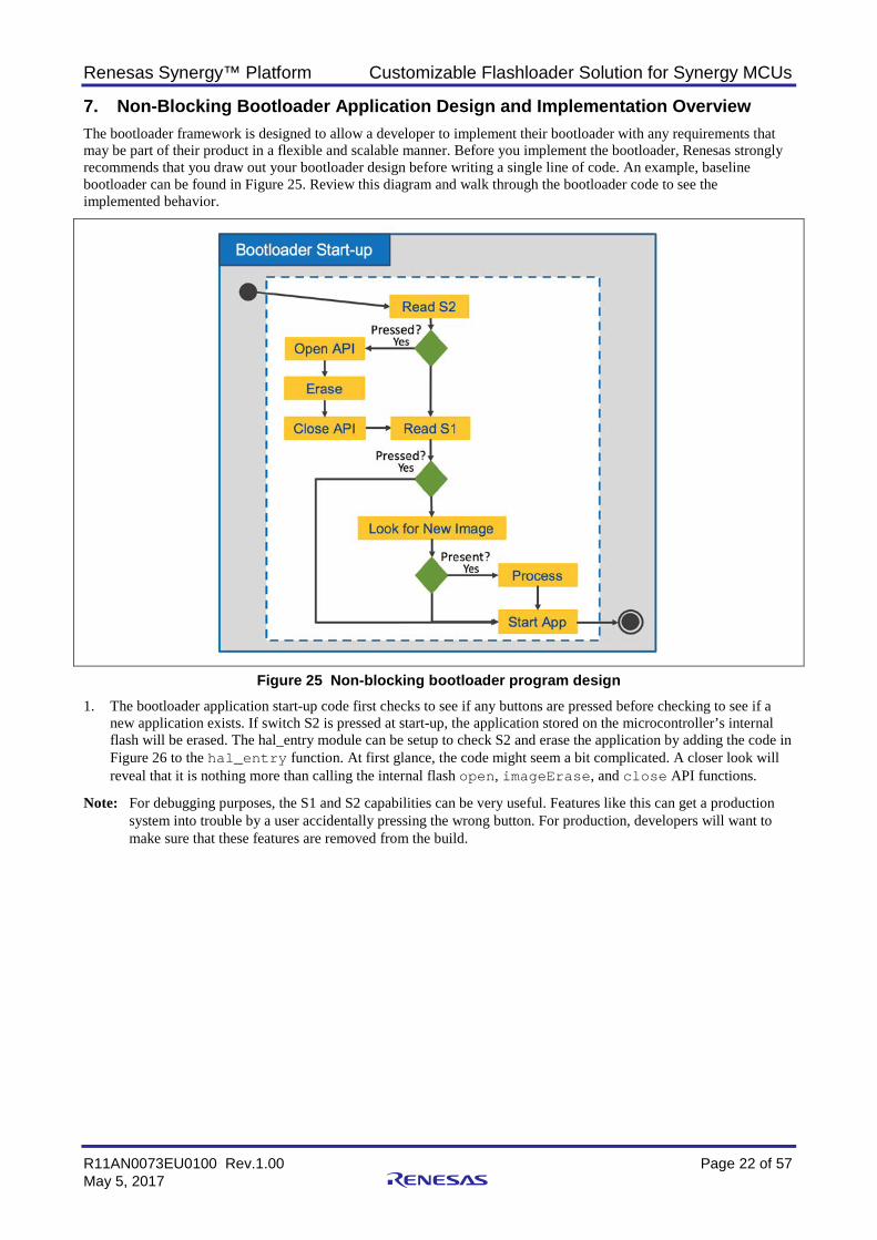
7. Non-Blocking Bootloader Application Design and Implementation Overview The bootloader framework is designed to allow a developer to implement their bootloader with any requirements that may be part of their product in a flexible and scalable manner. Before you implement the bootloader, Renesas strongly recommends that you draw out your bootloader design before writing a single line of code. An example, baseline bootloader can be found in Figure 25. Review this diagram and walk through the bootloader code to see the implemented behavior.
Figure 25 Non-blocking bootloader program design 1. The bootloader application start-up code first checks to see if any buttons are pressed before checking to see if a
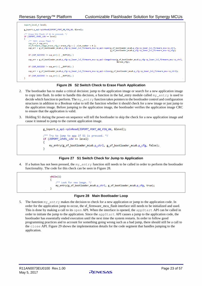
new application exists. If switch S2 is pressed at start-up, the application stored on the microcontroller’s internal flash will be erased. The hal_entry module can be setup to check S2 and erase the application by adding the code in Figure 26 to the hal_entry function. At first glance, the code might seem a bit complicated. A closer look will reveal that it is nothing more than calling the internal flash open, imageErase, and close API functions.
Note: For debugging purposes, the S1 and S2 capabilities can be very useful. Features like this can get a production system into trouble by a user accidentally pressing the wrong button. For production, developers will want to make sure that these features are removed from the build.
Renesas Synergy™ Platform Customizable Flashloader Solution for Synergy MCUs
R11AN0073EU0100 Rev.1.00 Page 23 of 57 May 5, 2017
Figure 26 S2 Switch Check to Erase Flash Application 2. The bootloader has to make a critical decision: jump to the application image or search for a new application image
to copy into flash. In order to handle this decision, a function in the hal_entry module called my_entry is used to decide which function to perform. The my_entry function takes pointers to the bootloader control and configuration structures in addition to a Boolean value to tell the function whether it should check for a new image or just jump to the application image. Before jumping to the application image, the bootloader verifies the application image CRC to ensure that the application is valid.
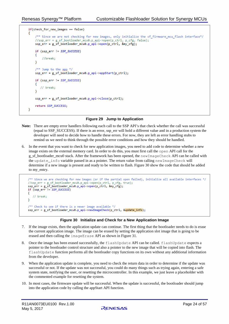
3. Holding S1 during the power-on sequence will tell the bootloader to skip the check for a new application image and cause it instead to jump to the current application image.
Figure 27 S1 Switch Check for Jump to Application
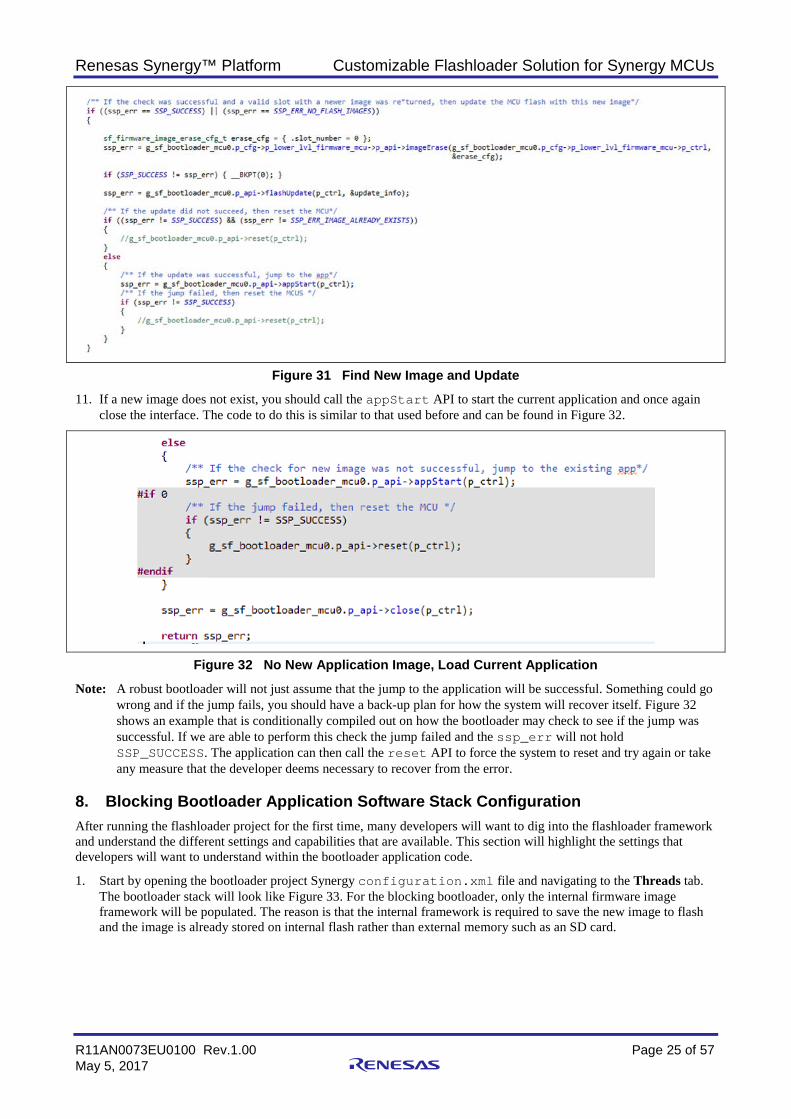
4. If a button has not been pressed, the my_entry function still needs to be called in order to perform the bootloader functionality. The code for this check can be seen in Figure 28.
Figure 28 Main Bootloader Loop
5. The function my_entry makes the decision to check for a new application or jump to the application code. In order for the application jump to occur, the sf_firmware_mcu_flash interface still needs to be initialized and used. This is done by making a call to its open API. When the interface is opened, the appStart API can be called in order to initiate the jump to the application. Since the appStart API causes a jump to the application code, the bootloader has essentially ended execution until the next time the system restarts. In order to follow good programming practices and to account for something going wrong such as a bad jump, there should still be a call to the close API. Figure 29 shows the implementation details for the code segment that handles jumping to the application.
Renesas Synergy™ Platform Customizable Flashloader Solution for Synergy MCUs
R11AN0073EU0100 Rev.1.00 Page 24 of 57 May 5, 2017
Figure 29 Jump to Application
Note: There are empty error handlers following each call to the SSP API’s that check whether the call was successful (equal to SSP_SUCCESS). If there is an error, ssp_err will hold a different value and in a production system the developer will need to decide how to handle these errors. For now, they are left as error handling stubs to remind us we need to think through the possible error conditions and how they should be handled.
6. In the event that you want to check for new application images, you need to add code to determine whether a new image exists on the external memory card. In order to do this, you must first call the open API call for the g_sf_bootloader_mcu0 stack. After the framework has been opened, the newImageCheck API can be called with the update_info variable passed in as a pointer. The return value from calling newImageCheck will determine if a new image is present and ready to be written to flash. Figure 30 show the code that should be added to my_entry.
Figure 30 Initialize and Check for a New Application Image 7. If the image exists, then the application update can continue. The first thing that the bootloader needs to do is erase
the current application image. The image can be erased by setting the application slot image that is going to be erased and then calling the imageErase API as shown in Figure 31.
8. Once the image has been erased successfully, the flashUpdate API can be called. flashUpdate expects a pointer to the bootloader control structure and also a pointer to the new image that will be copied into flash. The flashUpdate function performs all the bootloader copy functions on its own without any additional information from the developer.
9. When the application update is complete, you need to check the return data in order to determine if the update was successful or not. If the update was not successful, you could do many things such as trying again, entering a safe system state, notifying the user, or resetting the microcontroller. In this example, we just leave a placeholder with the commented example for resetting the system.
10. In most cases, the firmware update will be successful. When the update is successful, the bootloader should jump into the application code by calling the appStart API function.
Renesas Synergy™ Platform Customizable Flashloader Solution for Synergy MCUs
R11AN0073EU0100 Rev.1.00 Page 25 of 57 May 5, 2017
Figure 31 Find New Image and Update
11. If a new image does not exist, you should call the appStart API to start the current application and once again close the interface. The code to do this is similar to that used before and can be found in Figure 32.
Figure 32 No New Application Image, Load Current Application
Note: A robust bootloader will not just assume that the jump to the application will be successful. Something could go wrong and if the jump fails, you should have a back-up plan for how the system will recover itself. Figure 32 shows an example that is conditionally compiled out on how the bootloader may check to see if the jump was successful. If we are able to perform this check the jump failed and the ssp_err will not hold SSP_SUCCESS. The application can then call the reset API to force the system to reset and try again or take any measure that the developer deems necessary to recover from the error.
8. Blocking Bootloader Application Software Stack Configuration After running the flashloader project for the first time, many developers will want to dig into the flashloader framework and understand the different settings and capabilities that are available. This section will highlight the settings that developers will want to understand within the bootloader application code.
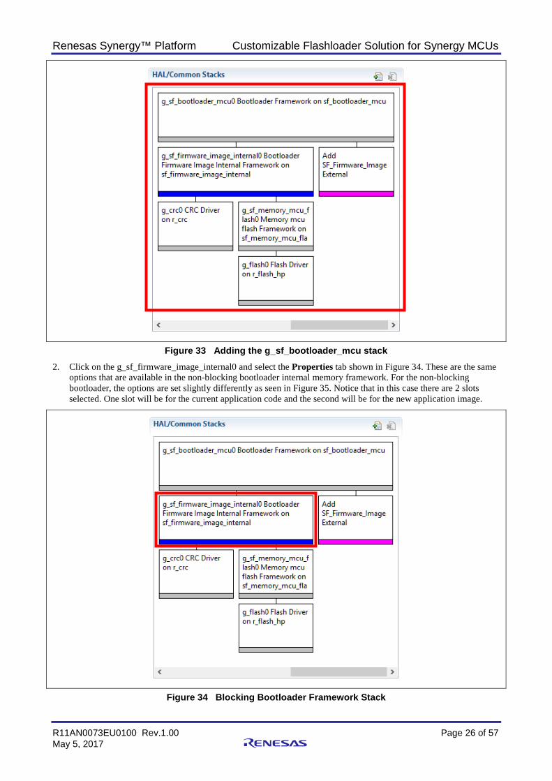
1. Start by opening the bootloader project Synergy configuration.xml file and navigating to the Threads tab. The bootloader stack will look like Figure 33. For the blocking bootloader, only the internal firmware image framework will be populated. The reason is that the internal framework is required to save the new image to flash and the image is already stored on internal flash rather than external memory such as an SD card.
Renesas Synergy™ Platform Customizable Flashloader Solution for Synergy MCUs
R11AN0073EU0100 Rev.1.00 Page 26 of 57 May 5, 2017
Figure 33 Adding the g_sf_bootloader_mcu stack 2. Click on the g_sf_firmware_image_internal0 and select the Properties tab shown in Figure 34. These are the same
options that are available in the non-blocking bootloader internal memory framework. For the non-blocking bootloader, the options are set slightly differently as seen in Figure 35. Notice that in this case there are 2 slots selected. One slot will be for the current application code and the second will be for the new application image.
Figure 34 Blocking Bootloader Framework Stack
Renesas Synergy™ Platform Customizable Flashloader Solution for Synergy MCUs
R11AN0073EU0100 Rev.1.00 Page 27 of 57 May 5, 2017
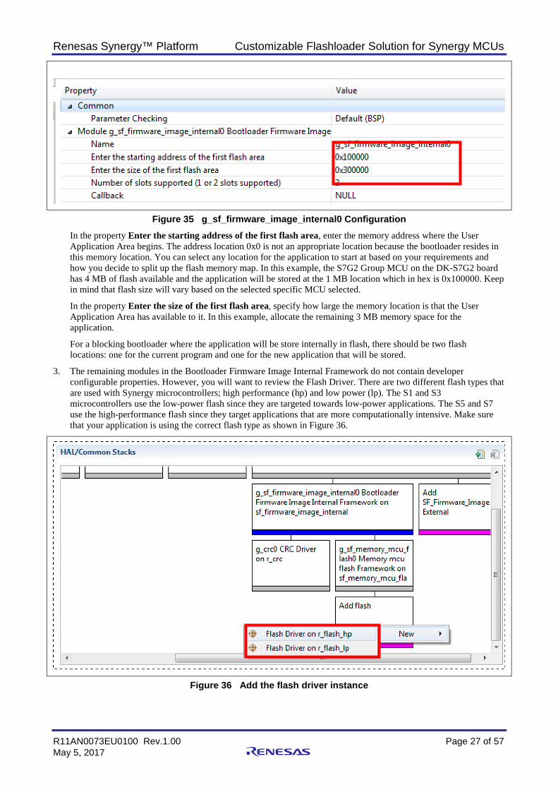
Figure 35 g_sf_firmware_image_internal0 Configuration In the property Enter the starting address of the first flash area, enter the memory address where the User Application Area begins. The address location 0x0 is not an appropriate location because the bootloader resides in this memory location. You can select any location for the application to start at based on your requirements and how you decide to split up the flash memory map. In this example, the S7G2 Group MCU on the DK-S7G2 board has 4 MB of flash available and the application will be stored at the 1 MB location which in hex is 0x100000. Keep in mind that flash size will vary based on the selected specific MCU selected.
In the property Enter the size of the first flash area, specify how large the memory location is that the User Application Area has available to it. In this example, allocate the remaining 3 MB memory space for the application.
For a blocking bootloader where the application will be store internally in flash, there should be two flash locations: one for the current program and one for the new application that will be stored.
3. The remaining modules in the Bootloader Firmware Image Internal Framework do not contain developer configurable properties. However, you will want to review the Flash Driver. There are two different flash types that are used with Synergy microcontrollers; high performance (hp) and low power (lp). The S1 and S3 microcontrollers use the low-power flash since they are targeted towards low-power applications. The S5 and S7 use the high-performance flash since they target applications that are more computationally intensive. Make sure that your application is using the correct flash type as shown in Figure 36.
Figure 36 Add the flash driver instance
Renesas Synergy™ Platform Customizable Flashloader Solution for Synergy MCUs
R11AN0073EU0100 Rev.1.00 Page 28 of 57 May 5, 2017
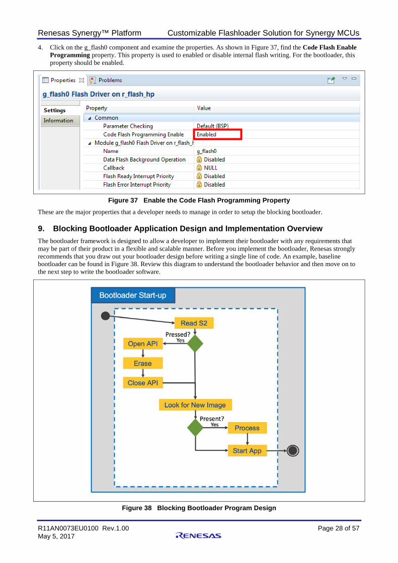
4. Click on the g_flash0 component and examine the properties. As shown in Figure 37, find the Code Flash Enable Programming property. This property is used to enabled or disable internal flash writing. For the bootloader, this property should be enabled.
Figure 37 Enable the Code Flash Programming Property These are the major properties that a developer needs to manage in order to setup the blocking bootloader.
9. Blocking Bootloader Application Design and Implementation Overview The bootloader framework is designed to allow a developer to implement their bootloader with any requirements that may be part of their product in a flexible and scalable manner. Before you implement the bootloader, Renesas strongly recommends that you draw out your bootloader design before writing a single line of code. An example, baseline bootloader can be found in Figure 38. Review this diagram to understand the bootloader behavior and then move on to the next step to write the bootloader software.
Figure 38 Blocking Bootloader Program Design
Renesas Synergy™ Platform Customizable Flashloader Solution for Synergy MCUs
R11AN0073EU0100 Rev.1.00 Page 29 of 57 May 5, 2017
Note: When there are multiple internal flash memory slots, it probably isn’t a good idea to allow a button press to erase the internal memory. While the activity diagram does show the ability to erase the internal flash, in the code that is developed, we will conditionally compile it out but provide it as a debugging tool for developers.
Note: Blinking LEDs in the bootloader to show that the system is processing and still doing something can be extremely useful. We will add code to control LED’s which are being absorbed by the check for image and process blocks.
1. In the project explorer, expand the project. Under the src folder, open the hal_entry.c module.
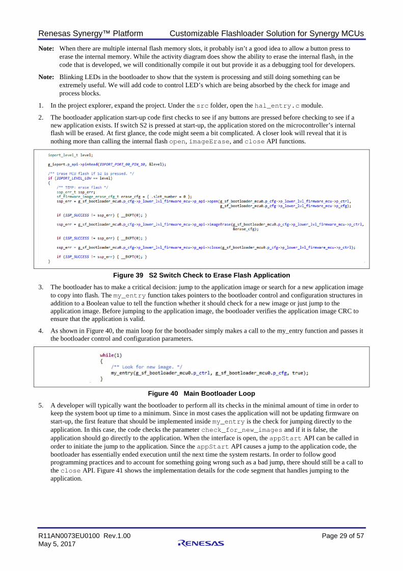
2. The bootloader application start-up code first checks to see if any buttons are pressed before checking to see if a new application exists. If switch S2 is pressed at start-up, the application stored on the microcontroller’s internal flash will be erased. At first glance, the code might seem a bit complicated. A closer look will reveal that it is nothing more than calling the internal flash open, imageErase, and close API functions.
Figure 39 S2 Switch Check to Erase Flash Application 3. The bootloader has to make a critical decision: jump to the application image or search for a new application image
to copy into flash. The my_entry function takes pointers to the bootloader control and configuration structures in addition to a Boolean value to tell the function whether it should check for a new image or just jump to the application image. Before jumping to the application image, the bootloader verifies the application image CRC to ensure that the application is valid.
4. As shown in Figure 40, the main loop for the bootloader simply makes a call to the my_entry function and passes it the bootloader control and configuration parameters.
Figure 40 Main Bootloader Loop 5. A developer will typically want the bootloader to perform all its checks in the minimal amount of time in order to
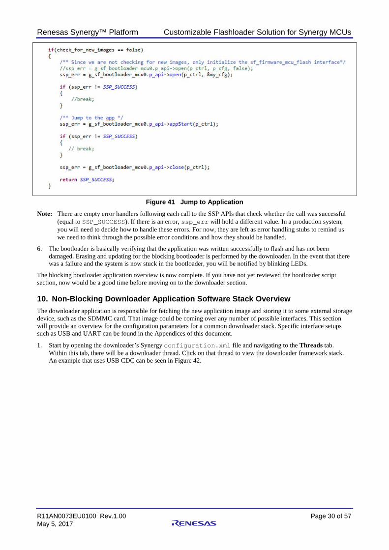
keep the system boot up time to a minimum. Since in most cases the application will not be updating firmware on start-up, the first feature that should be implemented inside my_entry is the check for jumping directly to the application. In this case, the code checks the parameter check_for_new_images and if it is false, the application should go directly to the application. When the interface is open, the appStart API can be called in order to initiate the jump to the application. Since the appStart API causes a jump to the application code, the bootloader has essentially ended execution until the next time the system restarts. In order to follow good programming practices and to account for something going wrong such as a bad jump, there should still be a call to the close API. Figure 41 shows the implementation details for the code segment that handles jumping to the application.
Renesas Synergy™ Platform Customizable Flashloader Solution for Synergy MCUs
R11AN0073EU0100 Rev.1.00 Page 30 of 57 May 5, 2017
Figure 41 Jump to Application
Note: There are empty error handlers following each call to the SSP APIs that check whether the call was successful (equal to SSP_SUCCESS). If there is an error, ssp_err will hold a different value. In a production system, you will need to decide how to handle these errors. For now, they are left as error handling stubs to remind us we need to think through the possible error conditions and how they should be handled.
6. The bootloader is basically verifying that the application was written successfully to flash and has not been damaged. Erasing and updating for the blocking bootloader is performed by the downloader. In the event that there was a failure and the system is now stuck in the bootloader, you will be notified by blinking LEDs.
The blocking bootloader application overview is now complete. If you have not yet reviewed the bootloader script section, now would be a good time before moving on to the downloader section.
10. Non-Blocking Downloader Application Software Stack Overview The downloader application is responsible for fetching the new application image and storing it to some external storage device, such as the SDMMC card. That image could be coming over any number of possible interfaces. This section will provide an overview for the configuration parameters for a common downloader stack. Specific interface setups such as USB and UART can be found in the Appendices of this document.
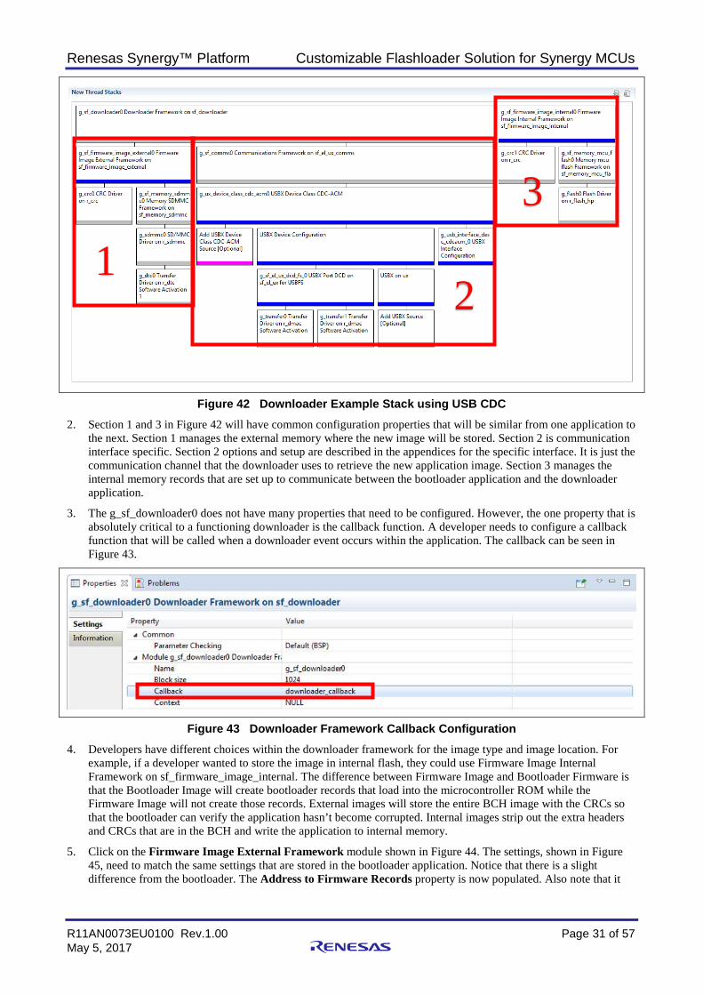
1. Start by opening the downloader’s Synergy configuration.xml file and navigating to the Threads tab. Within this tab, there will be a downloader thread. Click on that thread to view the downloader framework stack. An example that uses USB CDC can be seen in Figure 42.
Renesas Synergy™ Platform Customizable Flashloader Solution for Synergy MCUs
R11AN0073EU0100 Rev.1.00 Page 31 of 57 May 5, 2017
Figure 42 Downloader Example Stack using USB CDC 2. Section 1 and 3 in Figure 42 will have common configuration properties that will be similar from one application to
the next. Section 1 manages the external memory where the new image will be stored. Section 2 is communication interface specific. Section 2 options and setup are described in the appendices for the specific interface. It is just the communication channel that the downloader uses to retrieve the new application image. Section 3 manages the internal memory records that are set up to communicate between the bootloader application and the downloader application.
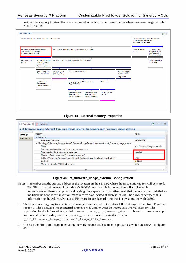
3. The g_sf_downloader0 does not have many properties that need to be configured. However, the one property that is absolutely critical to a functioning downloader is the callback function. A developer needs to configure a callback function that will be called when a downloader event occurs within the application. The callback can be seen in Figure 43.
Figure 43 Downloader Framework Callback Configuration 4. Developers have different choices within the downloader framework for the image type and image location. For
example, if a developer wanted to store the image in internal flash, they could use Firmware Image Internal Framework on sf_firmware_image_internal. The difference between Firmware Image and Bootloader Firmware is that the Bootloader Image will create bootloader records that load into the microcontroller ROM while the Firmware Image will not create those records. External images will store the entire BCH image with the CRCs so that the bootloader can verify the application hasn’t become corrupted. Internal images strip out the extra headers and CRCs that are in the BCH and write the application to internal memory.
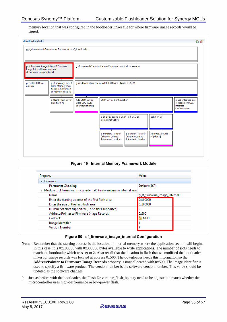
5. Click on the Firmware Image External Framework module shown in Figure 44. The settings, shown in Figure 45, need to match the same settings that are stored in the bootloader application. Notice that there is a slight difference from the bootloader. The Address to Firmware Records property is now populated. Also note that it
1 2
3
Renesas Synergy™ Platform Customizable Flashloader Solution for Synergy MCUs
R11AN0073EU0100 Rev.1.00 Page 32 of 57 May 5, 2017
matches the memory location that was configured in the bootloader linker file for where firmware image records would be stored.
Figure 44 External Memory Properties
Figure 45 sf_firmware_image_external Configuration
Note: Remember that the starting address is the location on the SD card where the image information will be stored. The SD card could be much larger than 0x400000 but since this is the maximum flash size on the microcontroller, there is no point in allocating more space than this. Also recall that the location in flash that we modified the bootloader linker for image records was located at address 0x500. The downloader needs this information so the Address/Pointer to Firmware Image Records property is now allocated with 0x500.
6. The downloader is going to have to write an application record to the internal flash storage. Recall from Figure 42 section 3. The Firmware Image Internal Framework is used to write the record into internal memory. The application header information is added to src/synergy_gen/common_data.c. In order to see an example for the application header, open the common_data.c file and locate the variable g_sf_firmware_image_internal0_image_file_header.
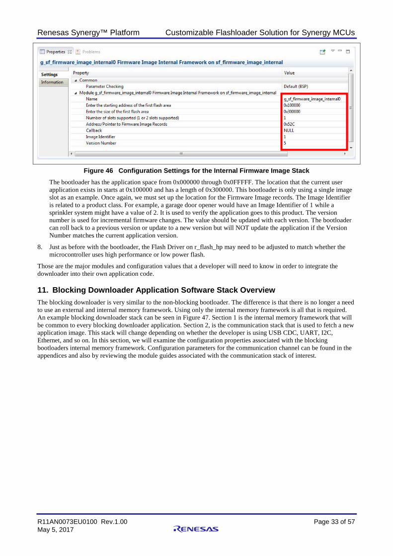
7. Click on the Firmware Image Internal Framework module and examine its properties, which are shown in Figure 46.
Renesas Synergy™ Platform Customizable Flashloader Solution for Synergy MCUs
R11AN0073EU0100 Rev.1.00 Page 33 of 57 May 5, 2017
Figure 46 Configuration Settings for the Internal Firmware Image Stack The bootloader has the application space from 0x000000 through 0x0FFFFF. The location that the current user application exists in starts at 0x100000 and has a length of 0x300000. This bootloader is only using a single image slot as an example. Once again, we must set up the location for the Firmware Image records. The Image Identifier is related to a product class. For example, a garage door opener would have an Image Identifier of 1 while a sprinkler system might have a value of 2. It is used to verify the application goes to this product. The version number is used for incremental firmware changes. The value should be updated with each version. The bootloader can roll back to a previous version or update to a new version but will NOT update the application if the Version Number matches the current application version.
8. Just as before with the bootloader, the Flash Driver on r_flash_hp may need to be adjusted to match whether the microcontroller uses high performance or low power flash.
Those are the major modules and configuration values that a developer will need to know in order to integrate the downloader into their own application code.
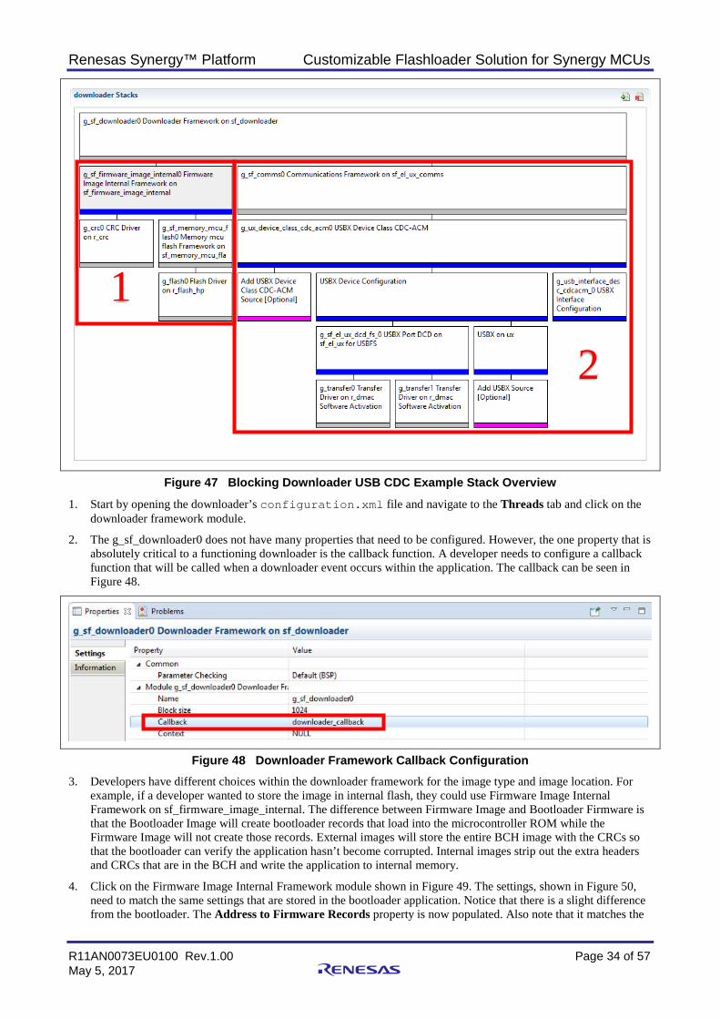
11. Blocking Downloader Application Software Stack Overview The blocking downloader is very similar to the non-blocking bootloader. The difference is that there is no longer a need to use an external and internal memory framework. Using only the internal memory framework is all that is required. An example blocking downloader stack can be seen in Figure 47. Section 1 is the internal memory framework that will be common to every blocking downloader application. Section 2, is the communication stack that is used to fetch a new application image. This stack will change depending on whether the developer is using USB CDC, UART, I2C, Ethernet, and so on. In this section, we will examine the configuration properties associated with the blocking bootloaders internal memory framework. Configuration parameters for the communication channel can be found in the appendices and also by reviewing the module guides associated with the communication stack of interest.
Renesas Synergy™ Platform Customizable Flashloader Solution for Synergy MCUs
R11AN0073EU0100 Rev.1.00 Page 34 of 57 May 5, 2017
Figure 47 Blocking Downloader USB CDC Example Stack Overview
1. Start by opening the downloader’s configuration.xml file and navigate to the Threads tab and click on the downloader framework module.
2. The g_sf_downloader0 does not have many properties that need to be configured. However, the one property that is absolutely critical to a functioning downloader is the callback function. A developer needs to configure a callback function that will be called when a downloader event occurs within the application. The callback can be seen in Figure 48.
Figure 48 Downloader Framework Callback Configuration 3. Developers have different choices within the downloader framework for the image type and image location. For
example, if a developer wanted to store the image in internal flash, they could use Firmware Image Internal Framework on sf_firmware_image_internal. The difference between Firmware Image and Bootloader Firmware is that the Bootloader Image will create bootloader records that load into the microcontroller ROM while the Firmware Image will not create those records. External images will store the entire BCH image with the CRCs so that the bootloader can verify the application hasn’t become corrupted. Internal images strip out the extra headers and CRCs that are in the BCH and write the application to internal memory.
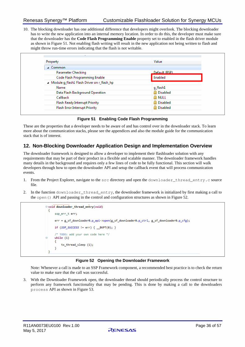
4. Click on the Firmware Image Internal Framework module shown in Figure 49. The settings, shown in Figure 50, need to match the same settings that are stored in the bootloader application. Notice that there is a slight difference from the bootloader. The Address to Firmware Records property is now populated. Also note that it matches the
1
2
Renesas Synergy™ Platform Customizable Flashloader Solution for Synergy MCUs
R11AN0073EU0100 Rev.1.00 Page 35 of 57 May 5, 2017
memory location that was configured in the bootloader linker file for where firmware image records would be stored.
Figure 49 Internal Memory Framework Module
Figure 50 sf_firmware_image_internal Configuration
Note: Remember that the starting address is the location in internal memory where the application section will begin. In this case, it is 0x100000 with 0x300000 bytes available to write applications. The number of slots needs to match the bootloader which was set to 2. Also recall that the location in flash that we modified the bootloader linker for image records was located at address 0x500. The downloader needs this information so the Address/Pointer to Firmware Image Records property is now allocated with 0x500. The image identifier is used to specify a firmware product. The version number is the software version number. This value should be updated as the software changes.
9. Just as before with the bootloader, the Flash Driver on r_flash_hp may need to be adjusted to match whether the microcontroller uses high-performance or low-power flash.
Renesas Synergy™ Platform Customizable Flashloader Solution for Synergy MCUs
R11AN0073EU0100 Rev.1.00 Page 36 of 57 May 5, 2017
10. The blocking downloader has one additional difference that developers might overlook. The blocking downloader has to write the new application into an internal memory location. In order to do this, the developer must make sure that the downloader has the Code Flash Programming Enable property set to enabled in the flash driver module as shown in Figure 51. Not enabling flash writing will result in the new application not being written to flash and might throw run-time errors indicating that the flash is not writable.
Figure 51 Enabling Code Flash Programming These are the properties that a developer needs to be aware of and has control over in the downloader stack. To learn more about the communication stacks, please see the appendices and also the module guide for the communication stack that is of interest.
12. Non-Blocking Downloader Application Design and Implementation Overview The downloader framework is designed to allow a developer to implement their flashloader solution with any requirements that may be part of their product in a flexible and scalable manner. The downloader framework handles many details in the background and requires only a few lines of code to be fully functional. This section will walk developers through how to open the downloader API and setup the callback event that will process communication events.
1. From the Project Explorer, navigate to the src directory and open the downloader_thread_entry.c source file.
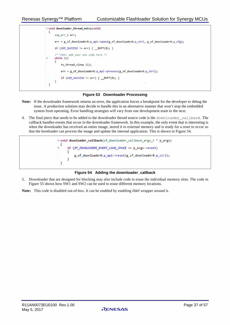
2. In the function downloader_thread_entry, the downloader framework is initialized by first making a call to the open() API and passing in the control and configuration structures as shown in Figure 52.
Figure 52 Opening the Downloader Framework Note: Whenever a call is made to an SSP Framework component, a recommended best practice is to check the return value to make sure that the call was successful.
3. With the Downloader Framework open, the downloader thread should periodically process the control structure to perform any framework functionality that may be pending. This is done by making a call to the downloaders process API as shown in Figure 53.
Renesas Synergy™ Platform Customizable Flashloader Solution for Synergy MCUs
R11AN0073EU0100 Rev.1.00 Page 37 of 57 May 5, 2017
Figure 53 Downloader Processing
Note: If the downloader framework returns an error, the application forces a breakpoint for the developer to debug the issue. A production solution may decide to handle this in an alternative manner that won’t stop the embedded system from operating. Error handling strategies will vary from one development team to the next.
4. The final piece that needs to be added to the downloader thread source code is the downloader_callback. The callback handles events that occur in the downloader framework. In this example, the only event that is interesting is when the downloader has received an entire image, stored it to external memory and is ready for a reset to occur so that the bootloader can process the image and update the internal application. This is shown in Figure 54.
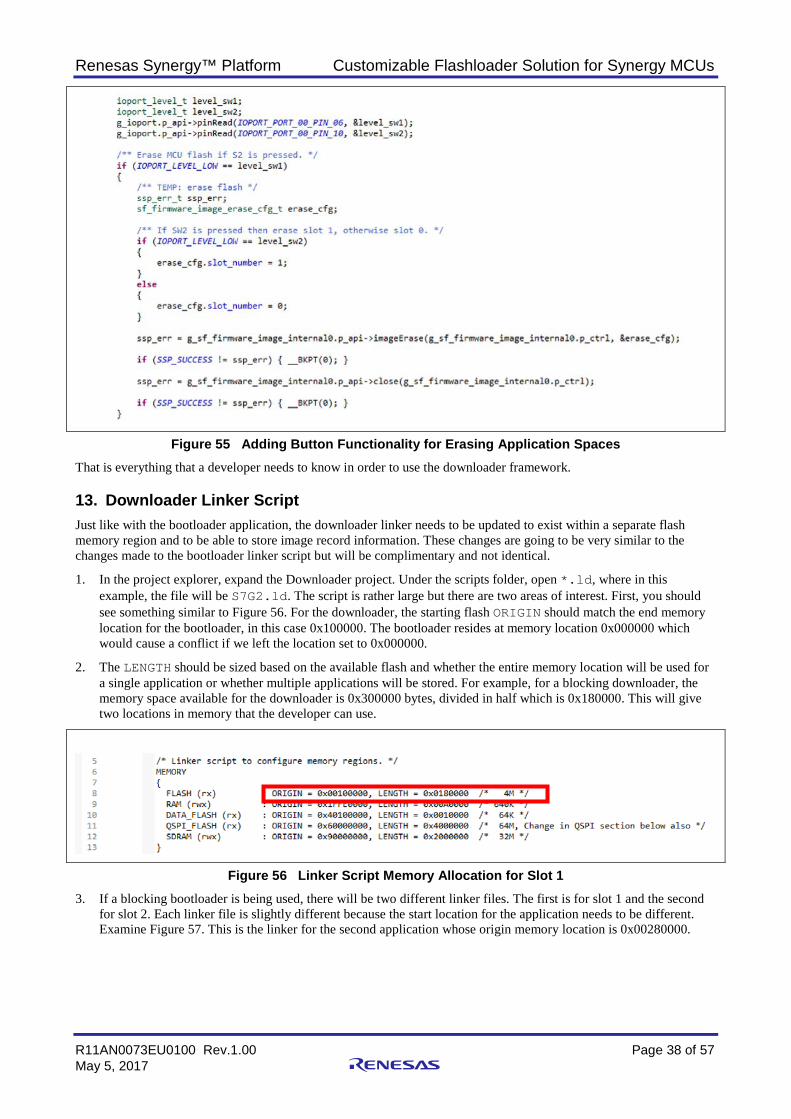
Figure 54 Adding the downloader_callback 5. Downloader that are designed for blocking may also include code to erase the individual memory slots. The code in
Figure 55 shows how SW1 and SW2 can be used to erase different memory locations.
Note: This code is disabled out-of-box. It can be enabled by enabling ifdef wrapper around it.
Renesas Synergy™ Platform Customizable Flashloader Solution for Synergy MCUs
R11AN0073EU0100 Rev.1.00 Page 38 of 57 May 5, 2017
Figure 55 Adding Button Functionality for Erasing Application Spaces That is everything that a developer needs to know in order to use the downloader framework.
13. Downloader Linker Script Just like with the bootloader application, the downloader linker needs to be updated to exist within a separate flash memory region and to be able to store image record information. These changes are going to be very similar to the changes made to the bootloader linker script but will be complimentary and not identical.
1. In the project explorer, expand the Downloader project. Under the scripts folder, open *.ld, where in this example, the file will be S7G2.ld. The script is rather large but there are two areas of interest. First, you should see something similar to Figure 56. For the downloader, the starting flash ORIGIN should match the end memory location for the bootloader, in this case 0x100000. The bootloader resides at memory location 0x000000 which would cause a conflict if we left the location set to 0x000000.
2. The LENGTH should be sized based on the available flash and whether the entire memory location will be used for a single application or whether multiple applications will be stored. For example, for a blocking downloader, the memory space available for the downloader is 0x300000 bytes, divided in half which is 0x180000. This will give two locations in memory that the developer can use.
Figure 56 Linker Script Memory Allocation for Slot 1 3. If a blocking bootloader is being used, there will be two different linker files. The first is for slot 1 and the second
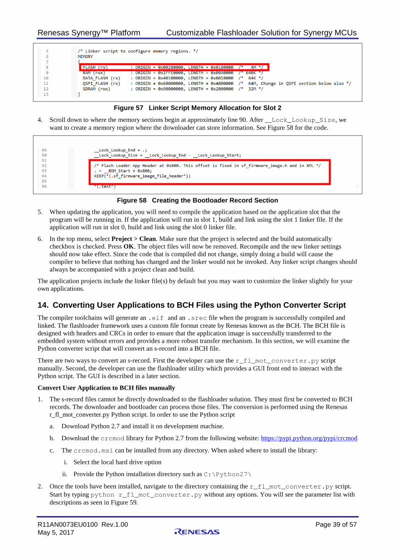
for slot 2. Each linker file is slightly different because the start location for the application needs to be different. Examine Figure 57. This is the linker for the second application whose origin memory location is 0x00280000.
Renesas Synergy™ Platform Customizable Flashloader Solution for Synergy MCUs
R11AN0073EU0100 Rev.1.00 Page 39 of 57 May 5, 2017
Figure 57 Linker Script Memory Allocation for Slot 2
4. Scroll down to where the memory sections begin at approximately line 90. After __Lock_Lookup_Size, we want to create a memory region where the downloader can store information. See Figure 58 for the code.
Figure 58 Creating the Bootloader Record Section 5. When updating the application, you will need to compile the application based on the application slot that the
program will be running in. If the application will run in slot 1, build and link using the slot 1 linker file. If the application will run in slot 0, build and link using the slot 0 linker file.
6. In the top menu, select Project > Clean. Make sure that the project is selected and the build automatically checkbox is checked. Press OK. The object files will now be removed. Recompile and the new linker settings should now take effect. Since the code that is compiled did not change, simply doing a build will cause the compiler to believe that nothing has changed and the linker would not be invoked. Any linker script changes should always be accompanied with a project clean and build.
The application projects include the linker file(s) by default but you may want to customize the linker slightly for your own applications.
14. Converting User Applications to BCH Files using the Python Converter Script The compiler toolchains will generate an .elf and an .srec file when the program is successfully compiled and linked. The flashloader framework uses a custom file format create by Renesas known as the BCH. The BCH file is designed with headers and CRCs in order to ensure that the application image is successfully transferred to the embedded system without errors and provides a more robust transfer mechanism. In this section, we will examine the Python converter script that will convert an s-record into a BCH file.
There are two ways to convert an s-record. First the developer can use the r_fl_mot_converter.py script manually. Second, the developer can use the flashloader utility which provides a GUI front end to interact with the Python script. The GUI is described in a later section.
Convert User Application to BCH files manually
1. The s-record files cannot be directly downloaded to the flashloader solution. They must first be converted to BCH records. The downloader and bootloader can process those files. The conversion is performed using the Renesas r_fl_mot_converter.py Python script. In order to use the Python script
a. Download Python 2.7 and install it on development machine.
b. Download the crcmod library for Python 2.7 from the following website: https://pypi.python.org/pypi/crcmod
c. The crcmod.msi can be installed from any directory. When asked where to install the library:
i. Select the local hard drive option
ii. Provide the Python installation directory such as C:\Python27\
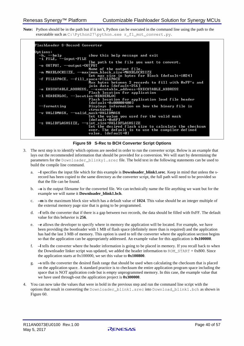
2. Once the tools have been installed, navigate to the directory containing the r_fl_mot_converter.py script. Start by typing python r_fl_mot_converter.py without any options. You will see the parameter list with descriptions as seen in Figure 59.
Renesas Synergy™ Platform Customizable Flashloader Solution for Synergy MCUs
R11AN0073EU0100 Rev.1.00 Page 40 of 57 May 5, 2017
Note: Python should be in the path but if it isn’t, Python can be executed in the command line using the path to the executable such as C:\Python27\python.exe r_fl_mot_convert.py.
Figure 59 S-Rec to BCH Converter Script Options 3. The next step is to identify which options are needed in order to run the converter script. Below is an example that
lays out the recommended information that should be provided for a conversion. We will start by determining the parameters for the Downloader_blinky1.srec file. The bold text in the following statements can be used to build the compile line command.
a. –I specifies the input file which for this example is Downloader_blink1.srec. Keep in mind that unless the s-record has been copied to the same directory as the converter script, the full path will need to be provided so that the file can be found.
b. –o is the output filename for the converted file. We can technically name the file anything we want but for the example we will name it Downloader_blink1.bch.
c. –m is the maximum block size which has a default value of 1024. This value should be an integer multiple of the external memory page size that is going to be programmed.
d. –f tells the converter that if there is a gap between two records, the data should be filled with 0xFF. The default value for this behavior is 256.
e. –e allows the developer to specify where in memory the application will be located. For example, we have been providing the bootloader with 1 MB of flash space (definitely more than is required) and the application has had the last 3 MB of memory. This option is used to tell the converter where the application section begins so that the application can be appropriately addressed. An example value for this application is 0x100000.
f. –l tells the converter where the header information is going to be placed in memory. If you recall back to when the Downloader linker script was updated, we added the header information to ROM_START + 0x800. Since the application starts at 0x100000, we set this value to 0x100800.
g. –s tells the converter the desired flash range that should be used when calculating the checksum that is placed on the application space. A standard practice is to checksum the entire application program space including the space that is NOT application code but is empty unprogrammed memory. In this case, the example value that we have used through-out the application project is 0x300000.
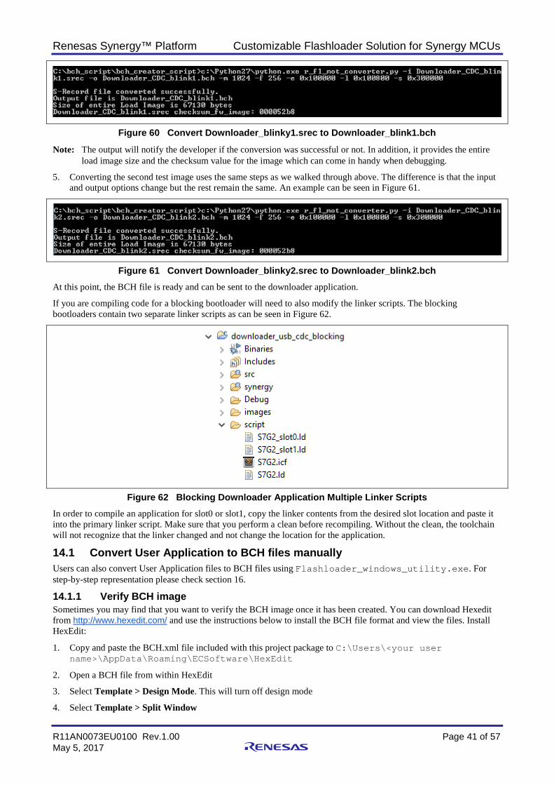
4. You can now take the values that were in bold in the previous step and run the command line script with the options that result in converting the Downloader_blink1.srec into Download_blink1.bch as shown in Figure 60.
Renesas Synergy™ Platform Customizable Flashloader Solution for Synergy MCUs
R11AN0073EU0100 Rev.1.00 Page 41 of 57 May 5, 2017
Figure 60 Convert Downloader_blinky1.srec to Downloader_blink1.bch
Note: The output will notify the developer if the conversion was successful or not. In addition, it provides the entire load image size and the checksum value for the image which can come in handy when debugging.
5. Converting the second test image uses the same steps as we walked through above. The difference is that the input and output options change but the rest remain the same. An example can be seen in Figure 61.
Figure 61 Convert Downloader_blinky2.srec to Downloader_blink2.bch At this point, the BCH file is ready and can be sent to the downloader application.
If you are compiling code for a blocking bootloader will need to also modify the linker scripts. The blocking bootloaders contain two separate linker scripts as can be seen in Figure 62.
Figure 62 Blocking Downloader Application Multiple Linker Scripts In order to compile an application for slot0 or slot1, copy the linker contents from the desired slot location and paste it into the primary linker script. Make sure that you perform a clean before recompiling. Without the clean, the toolchain will not recognize that the linker changed and not change the location for the application.
14.1 Convert User Application to BCH files manually Users can also convert User Application files to BCH files using Flashloader_windows_utility.exe. For step-by-step representation please check section 16.
14.1.1 Verify BCH image Sometimes you may find that you want to verify the BCH image once it has been created. You can download Hexedit from http://www.hexedit.com/ and use the instructions below to install the BCH file format and view the files. Install HexEdit:
1. Copy and paste the BCH.xml file included with this project package to C:\Users\<your user name>\AppData\Roaming\ECSoftware\HexEdit
2. Open a BCH file from within HexEdit
3. Select Template > Design Mode. This will turn off design mode
4. Select Template > Split Window
Renesas Synergy™ Platform Customizable Flashloader Solution for Synergy MCUs
R11AN0073EU0100 Rev.1.00 Page 42 of 57 May 5, 2017
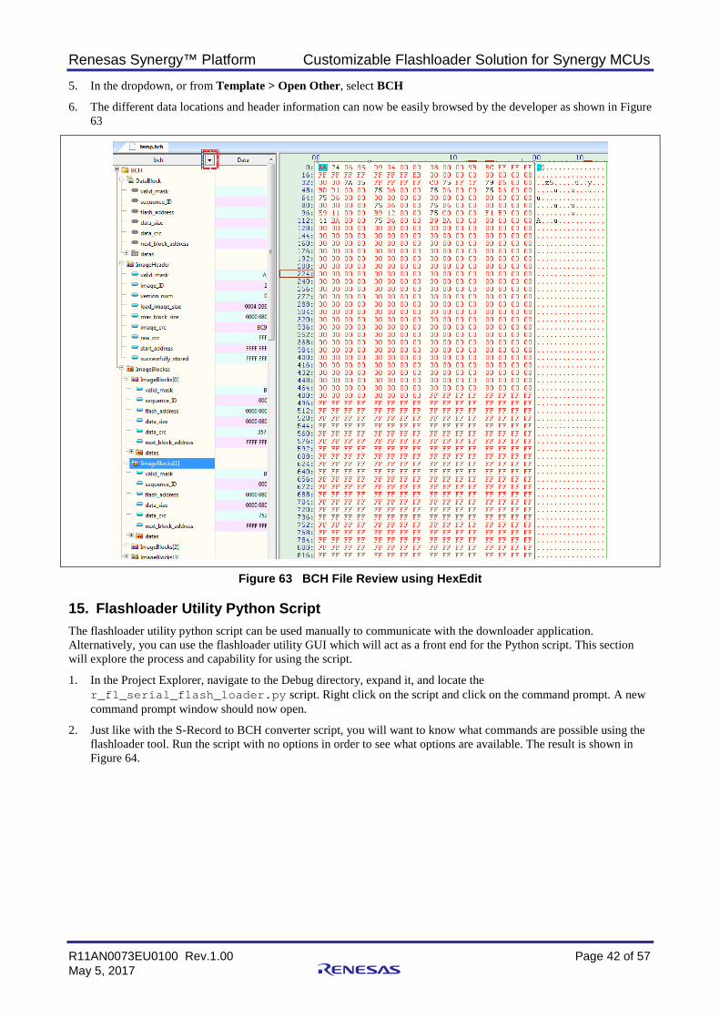
5. In the dropdown, or from Template > Open Other, select BCH
6. The different data locations and header information can now be easily browsed by the developer as shown in Figure 63
Figure 63 BCH File Review using HexEdit
15. Flashloader Utility Python Script The flashloader utility python script can be used manually to communicate with the downloader application. Alternatively, you can use the flashloader utility GUI which will act as a front end for the Python script. This section will explore the process and capability for using the script.
1. In the Project Explorer, navigate to the Debug directory, expand it, and locate the r_fl_serial_flash_loader.py script. Right click on the script and click on the command prompt. A new command prompt window should now open.
2. Just like with the S-Record to BCH converter script, you will want to know what commands are possible using the flashloader tool. Run the script with no options in order to see what options are available. The result is shown in Figure 64.
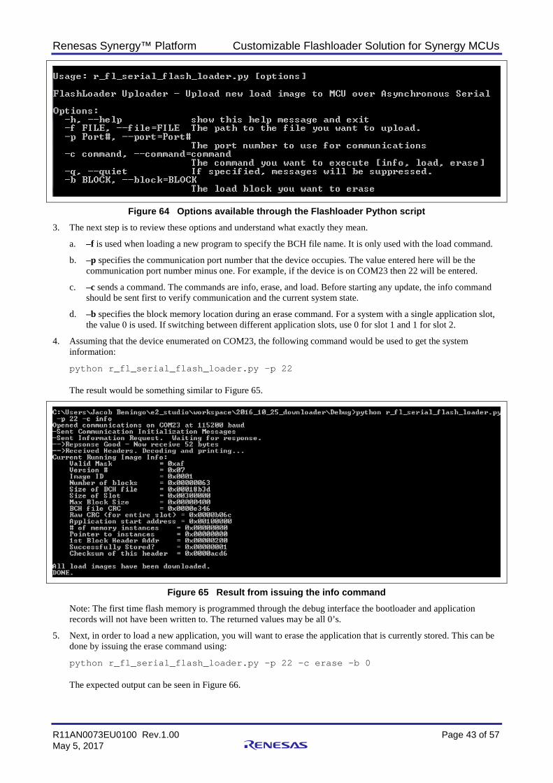
Renesas Synergy™ Platform Customizable Flashloader Solution for Synergy MCUs
R11AN0073EU0100 Rev.1.00 Page 43 of 57 May 5, 2017
Figure 64 Options available through the Flashloader Python script 3. The next step is to review these options and understand what exactly they mean.
a. –f is used when loading a new program to specify the BCH file name. It is only used with the load command.
b. –p specifies the communication port number that the device occupies. The value entered here will be the communication port number minus one. For example, if the device is on COM23 then 22 will be entered.
c. –c sends a command. The commands are info, erase, and load. Before starting any update, the info command should be sent first to verify communication and the current system state.
d. –b specifies the block memory location during an erase command. For a system with a single application slot, the value 0 is used. If switching between different application slots, use 0 for slot 1 and 1 for slot 2.
4. Assuming that the device enumerated on COM23, the following command would be used to get the system information:
python r_fl_serial_flash_loader.py –p 22
The result would be something similar to Figure 65.
Figure 65 Result from issuing the info command Note: The first time flash memory is programmed through the debug interface the bootloader and application records will not have been written to. The returned values may be all 0’s.
5. Next, in order to load a new application, you will want to erase the application that is currently stored. This can be done by issuing the erase command using:
python r_fl_serial_flash_loader.py –p 22 –c erase –b 0
The expected output can be seen in Figure 66.
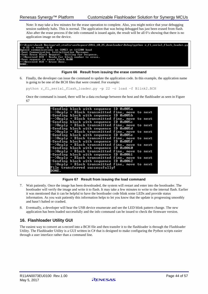
Renesas Synergy™ Platform Customizable Flashloader Solution for Synergy MCUs
R11AN0073EU0100 Rev.1.00 Page 44 of 57 May 5, 2017
Note: It may take a few minutes for the erase operation to complete. Also, you might notice that your debugging session suddenly halts. This is normal. The application that was being debugged has just been erased from flash. Also after the erase process if the info command is issued again, the result will be all 0’s showing that there is no application image on the device.
Figure 66 Result from issuing the erase command 6. Finally, the developer can issue the command to update the application code. In this example, the application name
is going to be one of the BCH files that were created. For example:
python r_fl_serial_flash_loader.py –p 22 –c load –f Blink2.BCH
Once the command is issued, there will be a data exchange between the host and the flashloader as seen in Figure 67
Figure 67 Result from issuing the load command 7. Wait patiently. Once the image has been downloaded, the system will restart and enter into the bootloader. The
bootloader will verify the image and write it to flash. It may take a few minutes to write to the internal flash. Earlier it was mentioned that it can be helpful to have the bootloader code blink some LEDs and provide status information. As you wait patiently this information helps to let you know that the update is progressing smoothly and hasn’t halted or crashed.
8. Eventually, a developer will hear the USB device enumerate and see the LED blink pattern change. The new application has been loaded successfully and the info command can be issued to check the firmware version.
16. Flashloader Utility GUI The easiest way to convert an s-record into a BCH file and then transfer it to the flashloader is through the Flashloader Utility. The Flashloader Utility is a GUI written in C# that is designed to make configuring the Python scripts easier through a user interface rather than a command line.
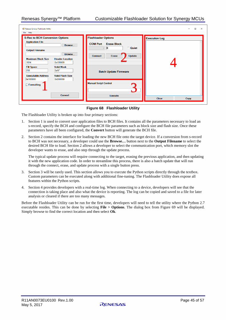
Renesas Synergy™ Platform Customizable Flashloader Solution for Synergy MCUs
R11AN0073EU0100 Rev.1.00 Page 45 of 57 May 5, 2017
Figure 68 Flashloader Utility The Flashloader Utility is broken up into four primary sections:
1. Section 1 is used to convert user application files to BCH files. It contains all the parameters necessary to load an s-record, specify the BCH and configure the BCH file parameters such as block size and flash size. Once these parameters have all been configured, the Convert button will generate the BCH file.
2. Section 2 contains the interface for loading the new BCH file onto the target device. If a conversion from s-record to BCH was not necessary, a developer could use the Browse… button next to the Output Filename to select the desired BCH file to load. Section 2 allows a developer to select the communication port, which memory slot the developer wants to erase, and also step through the update process.
The typical update process will require connecting to the target, erasing the previous application, and then updating it with the new application code. In order to streamline this process, there is also a batch update that will run through the connect, erase, and update process with a single button press.
3. Section 3 will be rarely used. This section allows you to execute the Python scripts directly through the textbox. Custom parameters can be executed along with additional fine-tuning. The Flashloader Utility does expose all features within the Python scripts.
4. Section 4 provides developers with a real-time log. When connecting to a device, developers will see that the connection is taking place and also what the device is reporting. The log can be copied and saved to a file for later analysis or cleared if there are too many messages.
Before the Flashloader Utility can be run for the first time, developers will need to tell the utility where the Python 2.7 executable resides. This can be done by selecting File > Options. The dialog box from Figure 69 will be displayed. Simply browse to find the correct location and then select Ok.
2
3
4
1
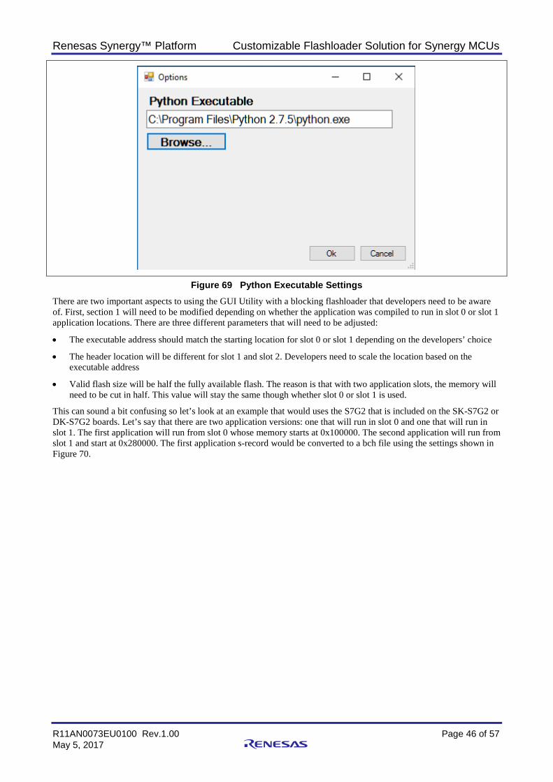
Renesas Synergy™ Platform Customizable Flashloader Solution for Synergy MCUs
R11AN0073EU0100 Rev.1.00 Page 46 of 57 May 5, 2017
Figure 69 Python Executable Settings There are two important aspects to using the GUI Utility with a blocking flashloader that developers need to be aware of. First, section 1 will need to be modified depending on whether the application was compiled to run in slot 0 or slot 1 application locations. There are three different parameters that will need to be adjusted:
• The executable address should match the starting location for slot 0 or slot 1 depending on the developers’ choice
• The header location will be different for slot 1 and slot 2. Developers need to scale the location based on the executable address
• Valid flash size will be half the fully available flash. The reason is that with two application slots, the memory will need to be cut in half. This value will stay the same though whether slot 0 or slot 1 is used.
This can sound a bit confusing so let’s look at an example that would uses the S7G2 that is included on the SK-S7G2 or DK-S7G2 boards. Let’s say that there are two application versions: one that will run in slot 0 and one that will run in slot 1. The first application will run from slot 0 whose memory starts at 0x100000. The second application will run from slot 1 and start at 0x280000. The first application s-record would be converted to a bch file using the settings shown in Figure 70.
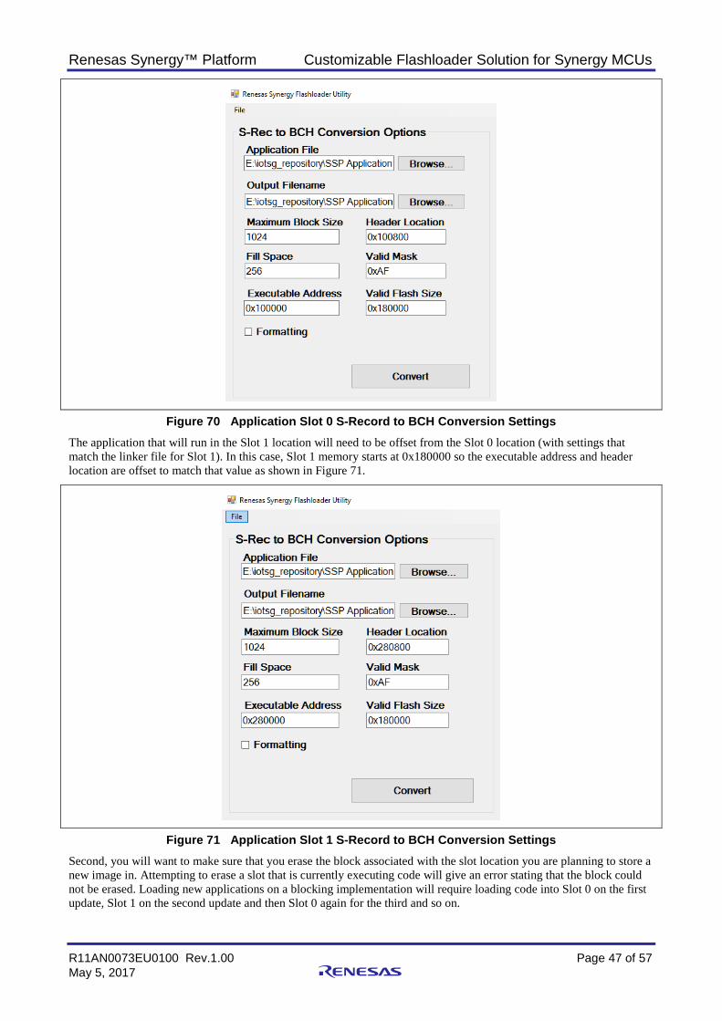
Renesas Synergy™ Platform Customizable Flashloader Solution for Synergy MCUs
R11AN0073EU0100 Rev.1.00 Page 47 of 57 May 5, 2017
Figure 70 Application Slot 0 S-Record to BCH Conversion Settings The application that will run in the Slot 1 location will need to be offset from the Slot 0 location (with settings that match the linker file for Slot 1). In this case, Slot 1 memory starts at 0x180000 so the executable address and header location are offset to match that value as shown in Figure 71.
Figure 71 Application Slot 1 S-Record to BCH Conversion Settings Second, you will want to make sure that you erase the block associated with the slot location you are planning to store a new image in. Attempting to erase a slot that is currently executing code will give an error stating that the block could not be erased. Loading new applications on a blocking implementation will require loading code into Slot 0 on the first update, Slot 1 on the second update and then Slot 0 again for the third and so on.
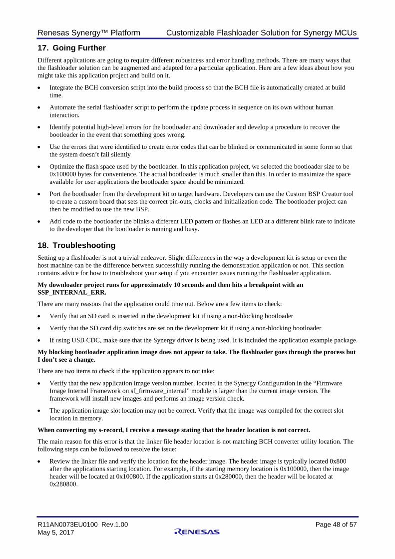
Renesas Synergy™ Platform Customizable Flashloader Solution for Synergy MCUs
R11AN0073EU0100 Rev.1.00 Page 48 of 57 May 5, 2017
17. Going Further Different applications are going to require different robustness and error handling methods. There are many ways that the flashloader solution can be augmented and adapted for a particular application. Here are a few ideas about how you might take this application project and build on it.
• Integrate the BCH conversion script into the build process so that the BCH file is automatically created at build time.
• Automate the serial flashloader script to perform the update process in sequence on its own without human interaction.
• Identify potential high-level errors for the bootloader and downloader and develop a procedure to recover the bootloader in the event that something goes wrong.
• Use the errors that were identified to create error codes that can be blinked or communicated in some form so that the system doesn’t fail silently
• Optimize the flash space used by the bootloader. In this application project, we selected the bootloader size to be 0x100000 bytes for convenience. The actual bootloader is much smaller than this. In order to maximize the space available for user applications the bootloader space should be minimized.
• Port the bootloader from the development kit to target hardware. Developers can use the Custom BSP Creator tool to create a custom board that sets the correct pin-outs, clocks and initialization code. The bootloader project can then be modified to use the new BSP.
• Add code to the bootloader the blinks a different LED pattern or flashes an LED at a different blink rate to indicate to the developer that the bootloader is running and busy.
18. Troubleshooting Setting up a flashloader is not a trivial endeavor. Slight differences in the way a development kit is setup or even the host machine can be the difference between successfully running the demonstration application or not. This section contains advice for how to troubleshoot your setup if you encounter issues running the flashloader application.
My downloader project runs for approximately 10 seconds and then hits a breakpoint with an SSP_INTERNAL_ERR.
There are many reasons that the application could time out. Below are a few items to check:
• Verify that an SD card is inserted in the development kit if using a non-blocking bootloader
• Verify that the SD card dip switches are set on the development kit if using a non-blocking bootloader
• If using USB CDC, make sure that the Synergy driver is being used. It is included the application example package.
My blocking bootloader application image does not appear to take. The flashloader goes through the process but I don’t see a change.
There are two items to check if the application appears to not take:
• Verify that the new application image version number, located in the Synergy Configuration in the “Firmware Image Internal Framework on sf_firmware_internal” module is larger than the current image version. The framework will install new images and performs an image version check.
• The application image slot location may not be correct. Verify that the image was compiled for the correct slot location in memory.
When converting my s-record, I receive a message stating that the header location is not correct.
The main reason for this error is that the linker file header location is not matching BCH converter utility location. The following steps can be followed to resolve the issue:
• Review the linker file and verify the location for the header image. The header image is typically located 0x800 after the applications starting location. For example, if the starting memory location is 0x100000, then the image header will be located at 0x100800. If the application starts at 0x280000, then the header will be located at 0x280800.
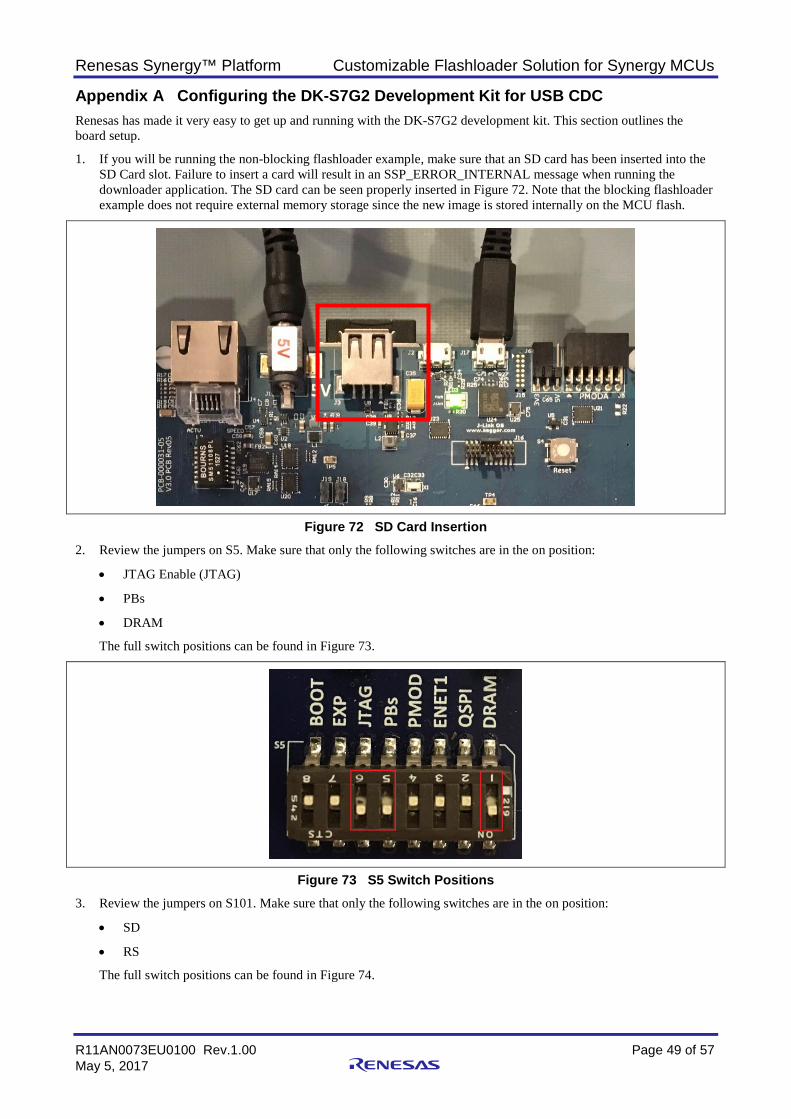
Renesas Synergy™ Platform Customizable Flashloader Solution for Synergy MCUs
R11AN0073EU0100 Rev.1.00 Page 49 of 57 May 5, 2017
Appendix A Configuring the DK-S7G2 Development Kit for USB CDC Renesas has made it very easy to get up and running with the DK-S7G2 development kit. This section outlines the board setup.
1. If you will be running the non-blocking flashloader example, make sure that an SD card has been inserted into the SD Card slot. Failure to insert a card will result in an SSP_ERROR_INTERNAL message when running the downloader application. The SD card can be seen properly inserted in Figure 72. Note that the blocking flashloader example does not require external memory storage since the new image is stored internally on the MCU flash.
Figure 72 SD Card Insertion 2. Review the jumpers on S5. Make sure that only the following switches are in the on position:
• JTAG Enable (JTAG)
• PBs
• DRAM
The full switch positions can be found in Figure 73.
Figure 73 S5 Switch Positions 3. Review the jumpers on S101. Make sure that only the following switches are in the on position:
• SD
• RS
The full switch positions can be found in Figure 74.
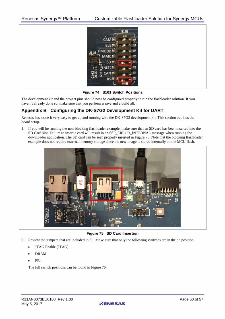
Renesas Synergy™ Platform Customizable Flashloader Solution for Synergy MCUs
R11AN0073EU0100 Rev.1.00 Page 50 of 57 May 5, 2017
Figure 74 S101 Switch Positions The development kit and the project pins should now be configured properly to run the flashloader solution. If you haven’t already done so, make sure that you perform a save and a build all.
Appendix B Configuring the DK-S7G2 Development Kit for UART Renesas has made it very easy to get up and running with the DK-S7G2 development kit. This section outlines the board setup.
1. If you will be running the non-blocking flashloader example, make sure that an SD card has been inserted into the SD Card slot. Failure to insert a card will result in an SSP_ERROR_INTERNAL message when running the downloader application. The SD card can be seen properly inserted in Figure 75. Note that the blocking flashloader example does not require external memory storage since the new image is stored internally on the MCU flash.
Figure 75 SD Card Insertion 2. Review the jumpers that are included in S5. Make sure that only the following switches are in the on position:
• JTAG Enable (JTAG)
• DRAM
• PBs
The full switch positions can be found in Figure 76.
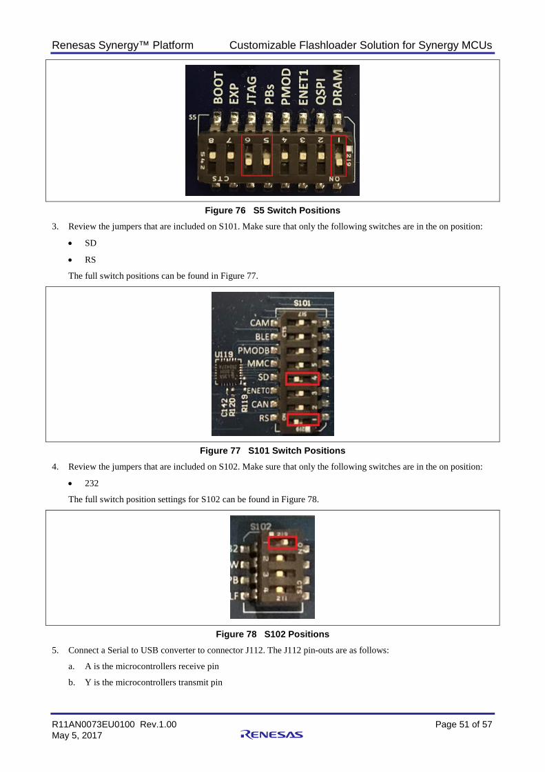
Renesas Synergy™ Platform Customizable Flashloader Solution for Synergy MCUs
R11AN0073EU0100 Rev.1.00 Page 51 of 57 May 5, 2017
Figure 76 S5 Switch Positions 3. Review the jumpers that are included on S101. Make sure that only the following switches are in the on position:
• SD
• RS
The full switch positions can be found in Figure 77.
Figure 77 S101 Switch Positions 4. Review the jumpers that are included on S102. Make sure that only the following switches are in the on position:
• 232
The full switch position settings for S102 can be found in Figure 78.
Figure 78 S102 Positions 5. Connect a Serial to USB converter to connector J112. The J112 pin-outs are as follows:
a. A is the microcontrollers receive pin
b. Y is the microcontrollers transmit pin
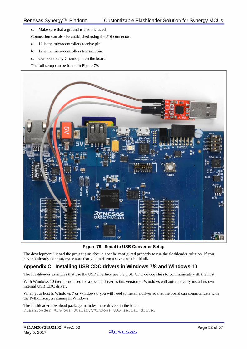
Renesas Synergy™ Platform Customizable Flashloader Solution for Synergy MCUs
R11AN0073EU0100 Rev.1.00 Page 52 of 57 May 5, 2017
c. Make sure that a ground is also included
Connection can also be established using the J10 connector.
a. 11 is the microcontrollers receive pin
b. 12 is the microcontrollers transmit pin.
c. Connect to any Ground pin on the board
The full setup can be found in Figure 79.
Figure 79 Serial to USB Converter Setup The development kit and the project pins should now be configured properly to run the flashloader solution. If you haven’t already done so, make sure that you perform a save and a build all.
Appendix C Installing USB CDC drivers in Windows 7/8 and Windows 10 The Flashloader examples that use the USB interface use the USB CDC device class to communicate with the host.
With Windows 10 there is no need for a special driver as this version of Windows will automatically install its own internal USB CDC driver.
When your host is Windows 7 or Windows 8 you will need to install a driver so that the board can communicate with the Python scripts running in Windows.
The flashloader download package includes these drivers in the folder Flashloader_Windows_Utility\Windows USB serial driver
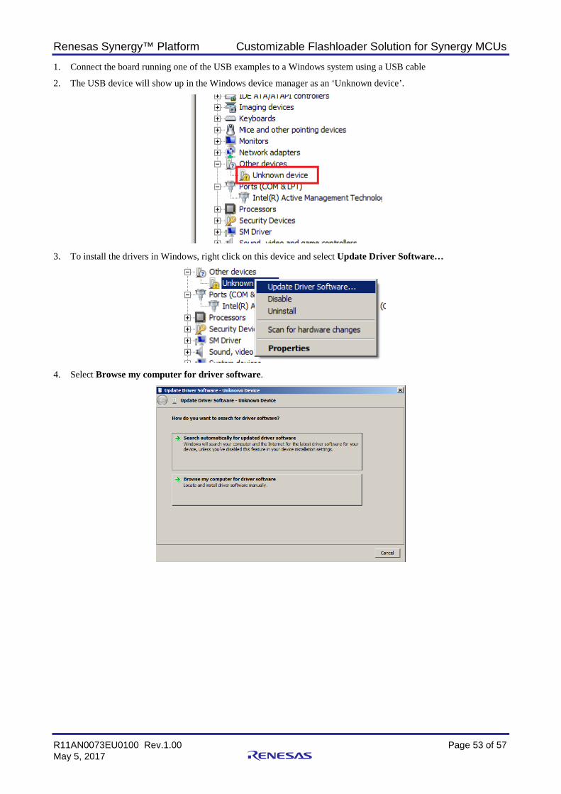
Renesas Synergy™ Platform Customizable Flashloader Solution for Synergy MCUs
R11AN0073EU0100 Rev.1.00 Page 53 of 57 May 5, 2017
1. Connect the board running one of the USB examples to a Windows system using a USB cable
2. The USB device will show up in the Windows device manager as an ‘Unknown device’.
3. To install the drivers in Windows, right click on this device and select Update Driver Software…
4. Select Browse my computer for driver software.
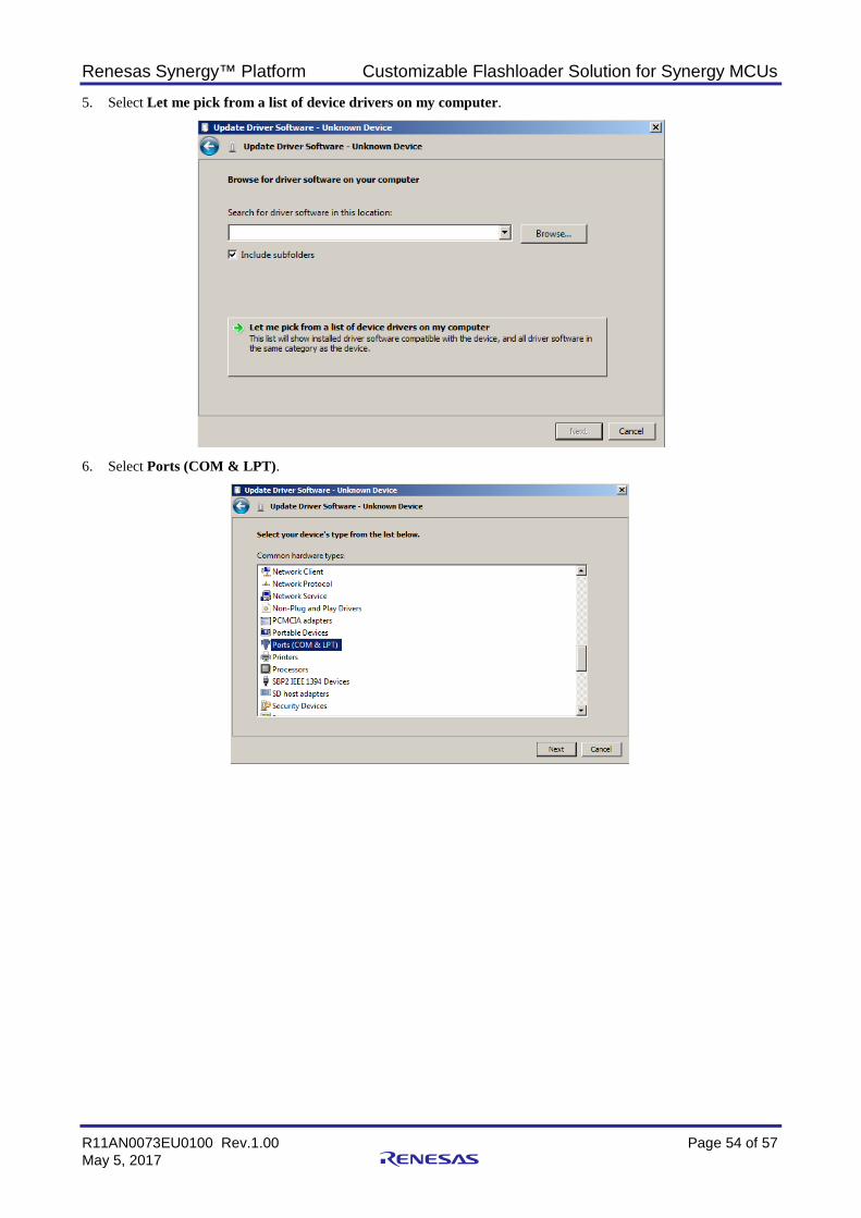
Renesas Synergy™ Platform Customizable Flashloader Solution for Synergy MCUs
R11AN0073EU0100 Rev.1.00 Page 54 of 57 May 5, 2017
5. Select Let me pick from a list of device drivers on my computer.
6. Select Ports (COM & LPT).
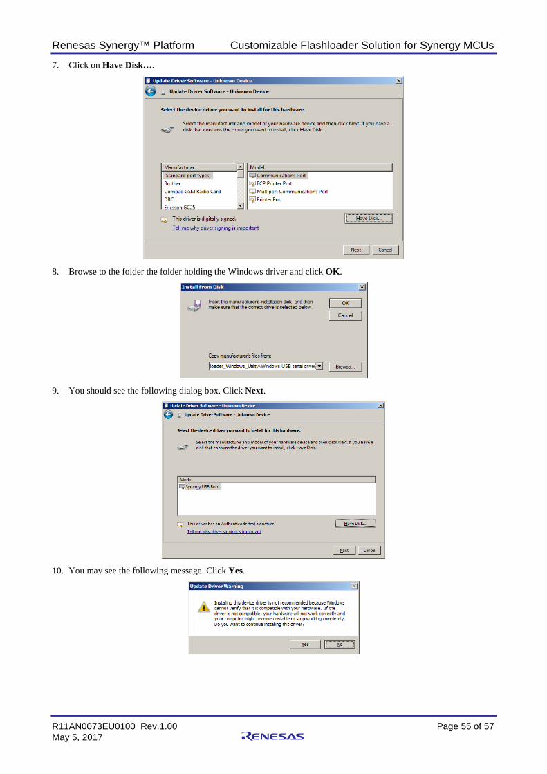
Renesas Synergy™ Platform Customizable Flashloader Solution for Synergy MCUs
R11AN0073EU0100 Rev.1.00 Page 55 of 57 May 5, 2017
7. Click on Have Disk….
8. Browse to the folder the folder holding the Windows driver and click OK.
9. You should see the following dialog box. Click Next.
10. You may see the following message. Click Yes.
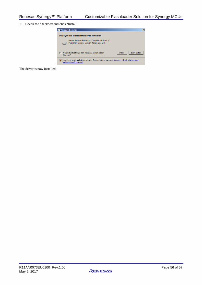
Renesas Synergy™ Platform Customizable Flashloader Solution for Synergy MCUs
R11AN0073EU0100 Rev.1.00 Page 56 of 57 May 5, 2017
11. Check the checkbox and click ‘Install’
The driver is now installed.
Renesas Synergy™ Platform Customizable Flashloader Solution for Synergy MCUs
R11AN0073EU0100 Rev.1.00 Page 57 of 57 May 5, 2017
Website and Support Support: https://synergygallery.renesas.com/support
Technical Contact Details:
• America: https://renesas.zendesk.com/anonymous_requests/new • Europe: https://www.renesas.com/en-eu/support/contact.html • Japan: https://www.renesas.com/ja-jp/support/contact.html
All trademarks and registered trademarks are the property of their respective owners.
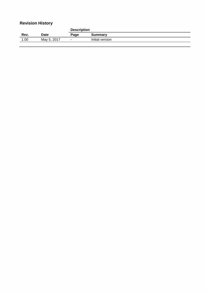
Revision History
Rev. Date Description Page Summary
1.00 May 5, 2017 - Initial version
Notice1. Descriptions of circuits, software and other related information in this document are provided only to illustrate the operation of semiconductor products and application examples. You are fully responsible for
the incorporation or any other use of the circuits, software, and information in the design of your product or system. Renesas Electronics disclaims any and all liability for any losses and damages incurred by
you or third parties arising from the use of these circuits, software, or information.
2. Renesas Electronics hereby expressly disclaims any warranties against and liability for infringement or any other disputes involving patents, copyrights, or other intellectual property rights of third parties, by or
arising from the use of Renesas Electronics products or technical information described in this document, including but not limited to, the product data, drawing, chart, program, algorithm, application
examples.
3. No license, express, implied or otherwise, is granted hereby under any patents, copyrights or other intellectual property rights of Renesas Electronics or others.
4. You shall not alter, modify, copy, or otherwise misappropriate any Renesas Electronics product, whether in whole or in part. Renesas Electronics disclaims any and all liability for any losses or damages
incurred by you or third parties arising from such alteration, modification, copy or otherwise misappropriation of Renesas Electronics products.
5. Renesas Electronics products are classified according to the following two quality grades: "Standard" and "High Quality". The intended applications for each Renesas Electronics product depends on the
product’s quality grade, as indicated below.
"Standard": Computers; office equipment; communications equipment; test and measurement equipment; audio and visual equipment; home electronic appliances; machine tools; personal electronic
equipment; and industrial robots etc.
"High Quality": Transportation equipment (automobiles, trains, ships, etc.); traffic control (traffic lights); large-scale communication equipment; key financial terminal systems; safety control equipment; etc.
Renesas Electronics products are neither intended nor authorized for use in products or systems that may pose a direct threat to human life or bodily injury (artificial life support devices or systems, surgical
implantations etc.), or may cause serious property damages (space and undersea repeaters; nuclear power control systems; aircraft control systems; key plant systems; military equipment; etc.). Renesas
Electronics disclaims any and all liability for any damages or losses incurred by you or third parties arising from the use of any Renesas Electronics product for which the product is not intended by Renesas
Electronics.
6. When using the Renesas Electronics products, refer to the latest product information (data sheets, user’s manuals, application notes, "General Notes for Handling and Using Semiconductor Devices" in the
reliability handbook, etc.), and ensure that usage conditions are within the ranges specified by Renesas Electronics with respect to maximum ratings, operating power supply voltage range, heat radiation
characteristics, installation, etc. Renesas Electronics disclaims any and all liability for any malfunctions or failure or accident arising out of the use of Renesas Electronics products beyond such specified
ranges.
7. Although Renesas Electronics endeavors to improve the quality and reliability of Renesas Electronics products, semiconductor products have specific characteristics such as the occurrence of failure at a
certain rate and malfunctions under certain use conditions. Further, Renesas Electronics products are not subject to radiation resistance design. Please ensure to implement safety measures to guard them
against the possibility of bodily injury, injury or damage caused by fire, and social damage in the event of failure or malfunction of Renesas Electronics products, such as safety design for hardware and
software including but not limited to redundancy, fire control and malfunction prevention, appropriate treatment for aging degradation or any other appropriate measures by your own responsibility as warranty
for your products/system. Because the evaluation of microcomputer software alone is very difficult and not practical, please evaluate the safety of the final products or systems manufactured by you.
8. Please contact a Renesas Electronics sales office for details as to environmental matters such as the environmental compatibility of each Renesas Electronics product. Please investigate applicable laws and
regulations that regulate the inclusion or use of controlled substances, including without limitation, the EU RoHS Directive carefully and sufficiently and use Renesas Electronics products in compliance with all
these applicable laws and regulations. Renesas Electronics disclaims any and all liability for damages or losses occurring as a result of your noncompliance with applicable laws and regulations.
9. Renesas Electronics products and technologies shall not be used for or incorporated into any products or systems whose manufacture, use, or sale is prohibited under any applicable domestic or foreign laws
or regulations. You shall not use Renesas Electronics products or technologies for (1) any purpose relating to the development, design, manufacture, use, stockpiling, etc., of weapons of mass destruction,
such as nuclear weapons, chemical weapons, or biological weapons, or missiles (including unmanned aerial vehicles (UAVs)) for delivering such weapons, (2) any purpose relating to the development,
design, manufacture, or use of conventional weapons, or (3) any other purpose of disturbing international peace and security, and you shall not sell, export, lease, transfer, or release Renesas Electronics
products or technologies to any third party whether directly or indirectly with knowledge or reason to know that the third party or any other party will engage in the activities described above. When exporting,
selling, transferring, etc., Renesas Electronics products or technologies, you shall comply with any applicable export control laws and regulations promulgated and administered by the governments of the
countries asserting jurisdiction over the parties or transactions.
10. Please acknowledge and agree that you shall bear all the losses and damages which are incurred from the misuse or violation of the terms and conditions described in this document, including this notice,
and hold Renesas Electronics harmless, if such misuse or violation results from your resale or making Renesas Electronics products available any third party.
11. This document shall not be reprinted, reproduced or duplicated in any form, in whole or in part, without prior written consent of Renesas Electronics.
12. Please contact a Renesas Electronics sales office if you have any questions regarding the information contained in this document or Renesas Electronics products.
(Note 1) "Renesas Electronics" as used in this document means Renesas Electronics Corporation and also includes its majority-owned subsidiaries.
(Note 2) "Renesas Electronics product(s)" means any product developed or manufactured by or for Renesas Electronics.
http://www.renesas.comRefer to "http://www.renesas.com/" for the latest and detailed information.
Renesas Electronics America Inc.2801 Scott Boulevard Santa Clara, CA 95050-2549, U.S.A.Tel: +1-408-588-6000, Fax: +1-408-588-6130Renesas Electronics Canada Limited9251 Yonge Street, Suite 8309 Richmond Hill, Ontario Canada L4C 9T3Tel: +1-905-237-2004Renesas Electronics Europe LimitedDukes Meadow, Millboard Road, Bourne End, Buckinghamshire, SL8 5FH, U.KTel: +44-1628-585-100, Fax: +44-1628-585-900Renesas Electronics Europe GmbHArcadiastrasse 10, 40472 Düsseldorf, GermanyTel: +49-211-6503-0, Fax: +49-211-6503-1327Renesas Electronics (China) Co., Ltd.Room 1709, Quantum Plaza, No.27 ZhiChunLu Haidian District, Beijing 100191, P.R.ChinaTel: +86-10-8235-1155, Fax: +86-10-8235-7679Renesas Electronics (Shanghai) Co., Ltd.Unit 301, Tower A, Central Towers, 555 Langao Road, Putuo District, Shanghai, P. R. China 200333Tel: +86-21-2226-0888, Fax: +86-21-2226-0999Renesas Electronics Hong Kong LimitedUnit 1601-1611, 16/F., Tower 2, Grand Century Place, 193 Prince Edward Road West, Mongkok, Kowloon, Hong KongTel: +852-2265-6688, Fax: +852 2886-9022Renesas Electronics Taiwan Co., Ltd.13F, No. 363, Fu Shing North Road, Taipei 10543, TaiwanTel: +886-2-8175-9600, Fax: +886 2-8175-9670Renesas Electronics Singapore Pte. Ltd.80 Bendemeer Road, Unit #06-02 Hyflux Innovation Centre, Singapore 339949Tel: +65-6213-0200, Fax: +65-6213-0300Renesas Electronics Malaysia Sdn.Bhd.Unit 1207, Block B, Menara Amcorp, Amcorp Trade Centre, No. 18, Jln Persiaran Barat, 46050 Petaling Jaya, Selangor Darul Ehsan, MalaysiaTel: +60-3-7955-9390, Fax: +60-3-7955-9510Renesas Electronics India Pvt. Ltd.No.777C, 100 Feet Road, HAL II Stage, Indiranagar, Bangalore, IndiaTel: +91-80-67208700, Fax: +91-80-67208777Renesas Electronics Korea Co., Ltd.12F., 234 Teheran-ro, Gangnam-Gu, Seoul, 135-080, KoreaTel: +82-2-558-3737, Fax: +82-2-558-5141
SALES OFFICES
© 2017 Renesas Electronics Corporation. All rights reserved.Colophon 6.0
(Rev.3.0-1 November 2016)