Embed Size (px)
Citation preview
1
Version 1.1 Update: July 2018
AQUALABO 90, Rue du Professeur P. Milliez 94506 Champigny-sur-Marne Tel.: 01 55 09 10 10
MES 5 & VB5 NUMERICAL SENSOR
User manual
2
Version 1.1 Update: July 2018
AQUALABO 90, Rue du Professeur P. Milliez 94506 Champigny-sur-Marne Tel.: 01 55 09 10 10
CONTENTS
1. GENERAL ..............................................................................................................3
2. CHARACTERISTICS .............................................................................................4 2.1 Technical characteristics. ............................................................................................................................... 4 2.2 CE compliance. ................................................................................................................................................ 5
3. DESCRIPTION. ......................................................................................................6 3.1 Product overview ............................................................................................................................................. 6 3.2 Applications ..................................................................................................................................................... 6 3.3 Construction and dimensions. ........................................................................................................................ 6 3.4 Communication. .............................................................................................................................................. 7
3.4.1 Modbus RTU registers. .............................................................................................................................. 7 3.4.2 SDI12 frame. .............................................................................................................................................. 7
3.5 Sampling rate ................................................................................................................................................... 7
4. INSTALLATION. ....................................................................................................8 4.1 Sensor installation option ............................................................................................................................... 8
4.1.1 Accessories for immersion installation. ..................................................................................................... 8 4.1.2 Accessories for PVC pipe-mounting ........................................................................................................ 11
4.2 Installation of the sensor in the accessories of assembly ............................................................................ 12 4.2.1 Insertion in a pole. .................................................................................................................................... 12 4.2.2 Insertion into the PVC in-pipe mounting system. .................................................................................... 12 3. Screw the union nut onto the fitting as far as the stop. .................................................................................. 13
4.3 Electrical connections. .................................................................................................................................. 13
5. STARTUP AND MAINTENANCE........................................................................ 13 5.1 Initial startup ................................................................................................................................................. 13 5.2 Calibration ..................................................................................................................................................... 14
5.2.1.Calibration in NTU .................................................................................................................................. 14 5.2.2.Calibration in mg/L .................................................................................................................................. 15
5.3 Maintenance .................................................................................................................................................. 15
3
Version 1.1 Update: July 2018
AQUALABO 90, Rue du Professeur P. Milliez 94506 Champigny-sur-Marne Tel.: 01 55 09 10 10
1. General
In order to maintain and ensure the good working order of the MES5 or VB5 sensor, users must comply with the safety precautions and warnings featured in this manual. Assembly and activation:
- Assembly, electrical connection, activation, operation and maintenance of the measuring system must only be carried out by specialist personnel authorized by the user of the facilities.
- Trained personnel must be familiar with and comply with the instructions in this manual.
- Make sure the power supply complies with the specifications before connecting the device.
- A clearly-labeled power switch must be installed near the device.
- Check all connections before turning the power on.
- Do not attempt to use damaged equipment: it may represent a hazard and should be labeled as faulty.
- Repairs must only be carried out by the manufacturer or by AQUALABO's sales after service department.
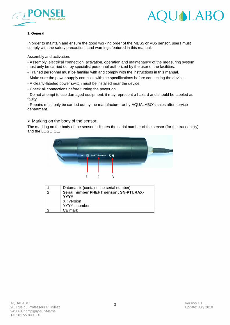
➢ Marking on the body of the sensor:
The marking on the body of the sensor indicates the serial number of the sensor (for the traceability) and the LOGO CE.
1 Datamatrix (contains the serial number)
2 Serial number PHEHT sensor : SN-PTURAX-YYYY X : version YYYY : number
3 CE mark
1 2 3
4
Version 1.1 Update: July 2018
AQUALABO 90, Rue du Professeur P. Milliez 94506 Champigny-sur-Marne Tel.: 01 55 09 10 10
2. Characteristics
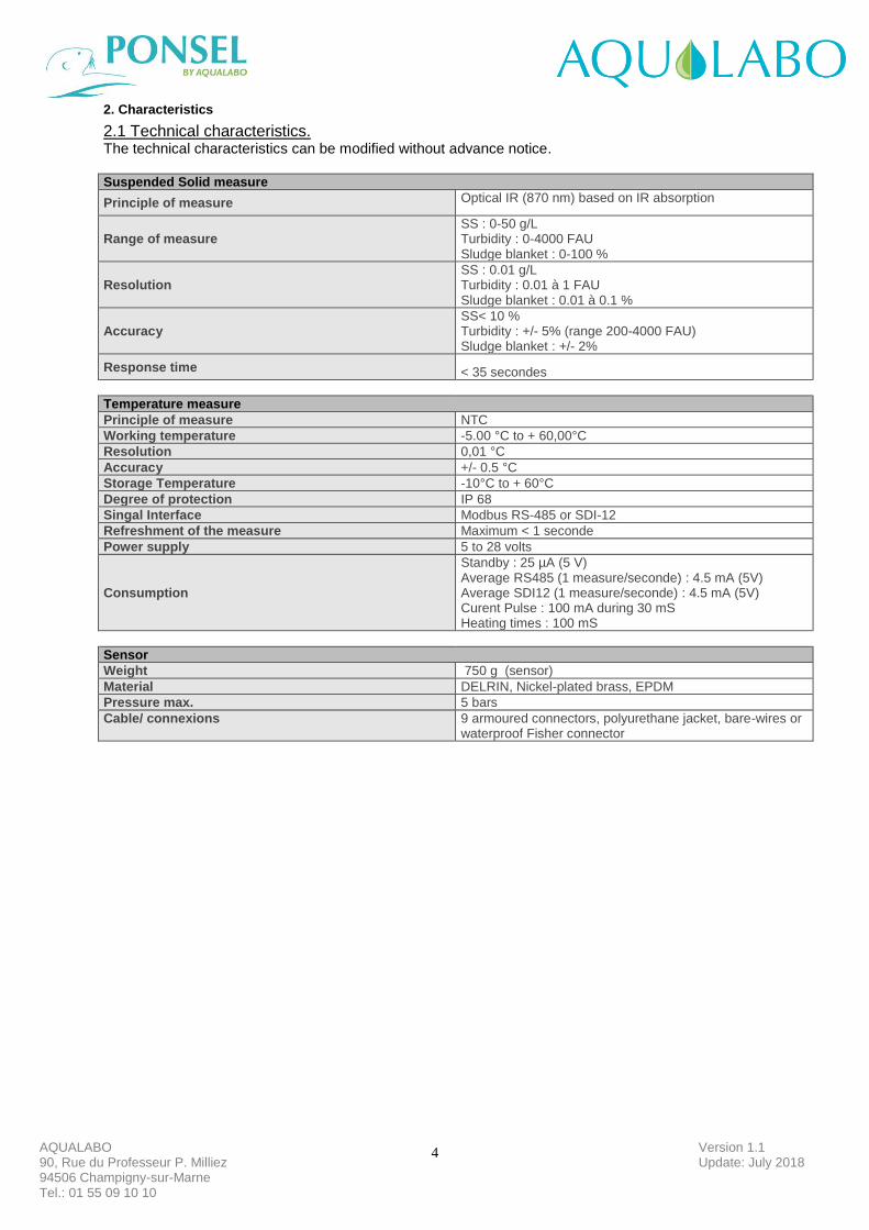
2.1 Technical characteristics. The technical characteristics can be modified without advance notice. Suspended Solid measure
Principle of measure Optical IR (870 nm) based on IR absorption
Range of measure SS : 0-50 g/L Turbidity : 0-4000 FAU Sludge blanket : 0-100 %
Resolution SS : 0.01 g/L Turbidity : 0.01 à 1 FAU Sludge blanket : 0.01 à 0.1 %
Accuracy SS< 10 % Turbidity : +/- 5% (range 200-4000 FAU) Sludge blanket : +/- 2%
Response time
< 35 secondes
Temperature measure
Principle of measure NTC
Working temperature -5.00 °C to + 60,00°C
Resolution 0,01 °C
Accuracy +/- 0.5 °C
Storage Temperature -10°C to + 60°C
Degree of protection IP 68
Singal Interface Modbus RS-485 or SDI-12
Refreshment of the measure Maximum < 1 seconde
Power supply 5 to 28 volts
Consumption
Standby : 25 µA (5 V) Average RS485 (1 measure/seconde) : 4.5 mA (5V) Average SDI12 (1 measure/seconde) : 4.5 mA (5V) Curent Pulse : 100 mA during 30 mS Heating times : 100 mS
Sensor
Weight 750 g (sensor)
Material DELRIN, Nickel-plated brass, EPDM
Pressure max. 5 bars
Cable/ connexions 9 armoured connectors, polyurethane jacket, bare-wires or waterproof Fisher connector
5
Version 1.1 Update: July 2018
AQUALABO 90, Rue du Professeur P. Milliez 94506 Champigny-sur-Marne Tel.: 01 55 09 10 10
2.2 CE compliance. Pursuant to the article 11 of the directive 89 / 336 / EEC relative to the electromagnetic compatibility. We declare that the digital sensor of the range DIGISENS sensors MES5 & VB5 were tested and declared in compliance with the European standards : Standard tests : EN 61326-1 edition 2013
Emission - EMC EN 55022 Class B Immunity - EN 61000-4-3 A EN 61000-4-2 B
EN 61000-4-6 A EN 61000-4-4 B
Shone disturbances : EN 55011B
Identification of the measurement process : composed of : 1- one probe 2- Ponsel’s cable.
EN 61000-4-5 Not concerned for sensors with a cable lower or equal to 30 M Commercial name : DIGISENS range Manufacturer AQUALABO – Ponsel Brand
115 Rue Michel MARION 56850 CAUDAN
Responsible UE : AQUALABO – Ponsel Brand
115 Rue Michel MARION 56850 CAUDAN
6
Version 1.1 Update: July 2018
AQUALABO 90, Rue du Professeur P. Milliez 94506 Champigny-sur-Marne Tel.: 01 55 09 10 10
3. Description.
3.1 Product overview
The principle of measure is based on the mitigation of the Infra-Red signal in 870 nm through an optical path of 5mm. The sensor delivers measures in Suspended Solid (g/l), Turbidity (FAU) and Sludge Blanket detection in % of transmission IR. For a better precision, the optics of the sensor are regulated in temperature. For a measure of Suspended Solid, the sensor is directly calibrated on the material to be measured (sample of sludge). In Turbidimeter version the sensor delivers measures on a range 0-4000 FAU (Formazine Attenuation Unit) and is calibrated with solutions of Formazine. The sensor stores its calibration data and history directly in the sensor electronics. This means that it can be used quickly anywhere without the need for constant recalibration. Finally, in sludge blanket detection the measure is delivered in % of transmission IR. Suitable fittings are required for the installation of the sensor, e.g. in order to prevent the influence of extraneous light and any possibly resulting measurement errors. Corresponding immersion, suspended, and flow fittings are available.
3.2 Applications
The compact and robust sensor is particularly well suited to the following typical areas of application: - Urban Waste water treatment (Inlet/ sewage water (SS, Turbidity), Aeration basin (SS),
Settling tank (sludge blanket), Outlet (Turbidity). - Treatment of industrial effluents (Aeration basin (SS)), Clarifier (Sludge blanket), Outlet
(Turbidity) - Sludge treatment (Centrifugation) - Dredging site (turbidity)
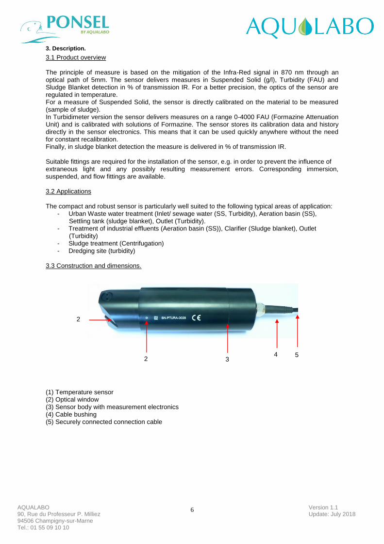
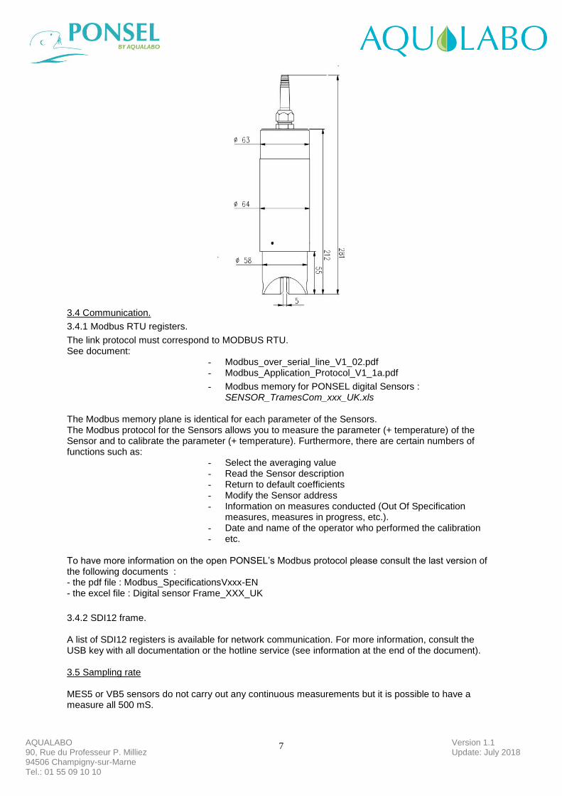
3.3 Construction and dimensions.
(1) Temperature sensor (2) Optical window (3) Sensor body with measurement electronics (4) Cable bushing (5) Securely connected connection cable
2
2 3 4 5
7
Version 1.1 Update: July 2018
AQUALABO 90, Rue du Professeur P. Milliez 94506 Champigny-sur-Marne Tel.: 01 55 09 10 10
3.4 Communication.
3.4.1 Modbus RTU registers.
The link protocol must correspond to MODBUS RTU. See document:
- Modbus_over_serial_line_V1_02.pdf - Modbus_Application_Protocol_V1_1a.pdf
- Modbus memory for PONSEL digital Sensors : SENSOR_TramesCom_xxx_UK.xls
The Modbus memory plane is identical for each parameter of the Sensors. The Modbus protocol for the Sensors allows you to measure the parameter (+ temperature) of the Sensor and to calibrate the parameter (+ temperature). Furthermore, there are certain numbers of functions such as:
- Select the averaging value - Read the Sensor description - Return to default coefficients - Modify the Sensor address - Information on measures conducted (Out Of Specification
measures, measures in progress, etc.). - Date and name of the operator who performed the calibration - etc.
To have more information on the open PONSEL’s Modbus protocol please consult the last version of the following documents : - the pdf file : Modbus_SpecificationsVxxx-EN - the excel file : Digital sensor Frame_XXX_UK
3.4.2 SDI12 frame.
A list of SDI12 registers is available for network communication. For more information, consult the USB key with all documentation or the hotline service (see information at the end of the document). 3.5 Sampling rate MES5 or VB5 sensors do not carry out any continuous measurements but it is possible to have a measure all 500 mS.
8
Version 1.1 Update: July 2018
AQUALABO 90, Rue du Professeur P. Milliez 94506 Champigny-sur-Marne Tel.: 01 55 09 10 10
4. Installation.
4.1 Sensor installation option
For the installation of the sensors in condition of immersion or in-pipe insertion, we advise to use accessories adapted and proposed by AQUALABO.
4.1.1 Accessories for immersion installation. In immersion condition, it is necessary to maintain the sensor by the body and not to leave the sensor suspended by the cable at the risk of damaging the sensor AQUALABO proposes a range or pole (short and long version) in order to install the sensor in open basins. It can be positioned a considerable distance from the basin edge with the bracket suspended on a chain, for example. Please note the following when planning your set-up: • The fitting must be easily accessible to allow the sensor or the fitting itself to be maintained and cleaned regularly • Do not allow the fitting (and thus also the sensor) to swing against and hit the basin edge • When working with systems involving pressure and/or temperature, ensure that the fitting and sensor meet all relevant requirements • The system designer must check that the materials in the fitting and sensor are suitable for the measurement (chemical compatibility, for instance)
Material PVC
Admissible temperature 0 to 60 °C
Pressure max. 5 bars
9
Version 1.1 Update: July 2018
AQUALABO 90, Rue du Professeur P. Milliez 94506 Champigny-sur-Marne Tel.: 01 55 09 10 10
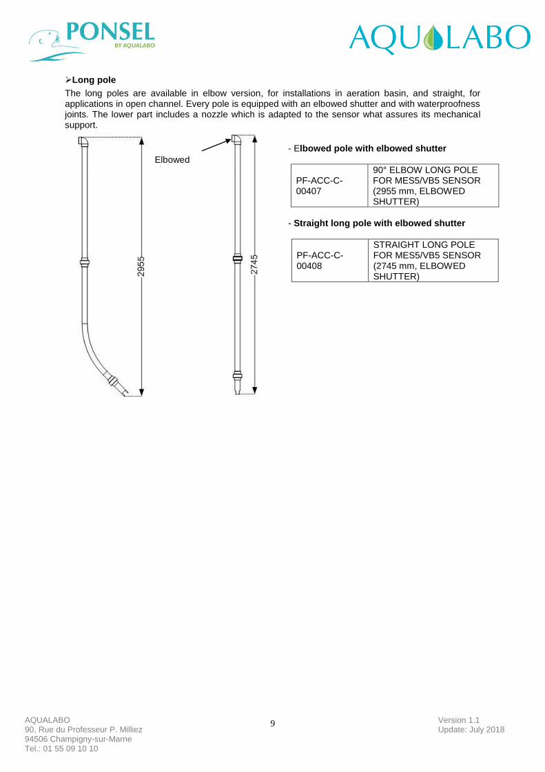
➢Long pole
The long poles are available in elbow version, for installations in aeration basin, and straight, for applications in open channel. Every pole is equipped with an elbowed shutter and with waterproofness joints. The lower part includes a nozzle which is adapted to the sensor what assures its mechanical support.
Elbowed shutter
- Elbowed pole with elbowed shutter
PF-ACC-C-00407
90° ELBOW LONG POLE FOR MES5/VB5 SENSOR (2955 mm, ELBOWED SHUTTER)
- Straight long pole with elbowed shutter
PF-ACC-C-00408
STRAIGHT LONG POLE FOR MES5/VB5 SENSOR (2745 mm, ELBOWED SHUTTER)
10
Version 1.1 Update: July 2018
AQUALABO 90, Rue du Professeur P. Milliez 94506 Champigny-sur-Marne Tel.: 01 55 09 10 10
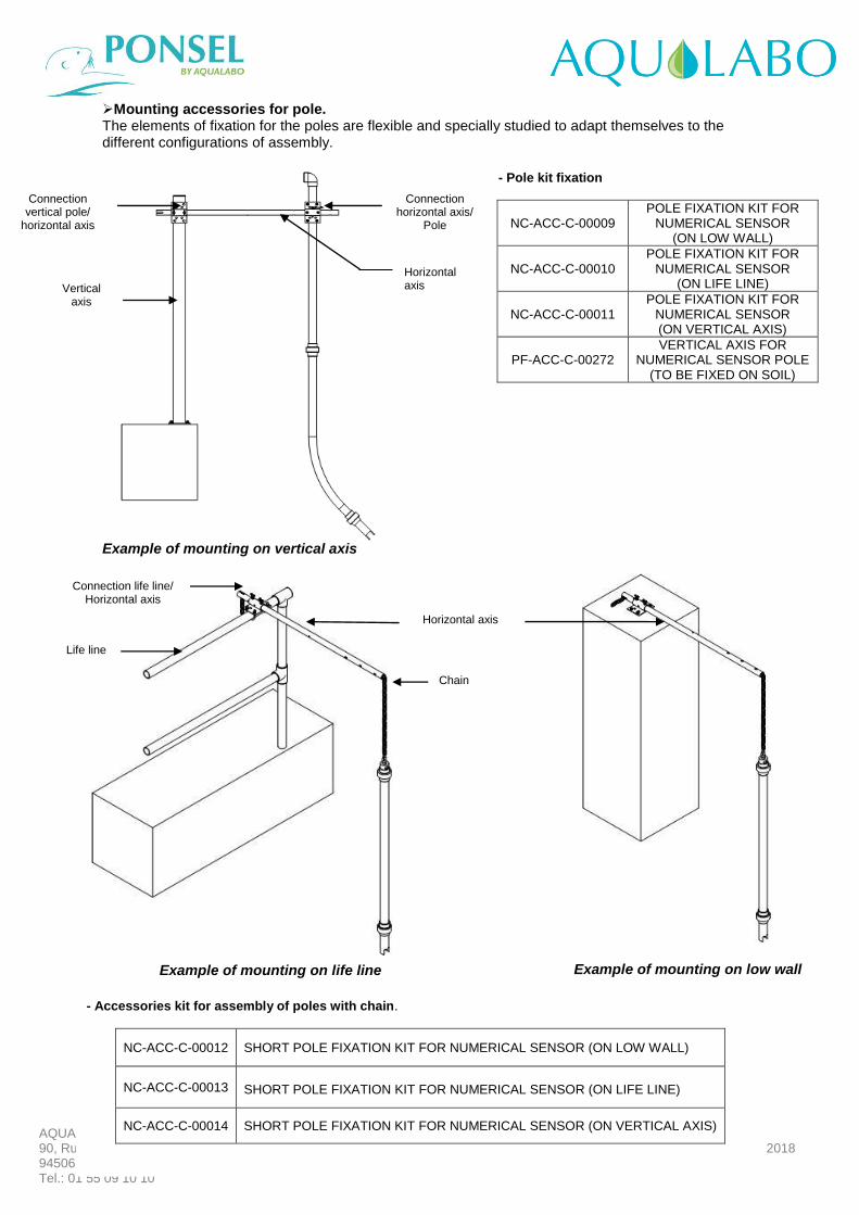
➢Mounting accessories for pole. The elements of fixation for the poles are flexible and specially studied to adapt themselves to the different configurations of assembly.
Example of mounting on vertical axis Exemple de montage sur garde-corps
Vertical axis
Connection vertical pole/
horizontal axis
Connection horizontal axis/
Pole
Horizontal axis
- Pole kit fixation
NC-ACC-C-00009 POLE FIXATION KIT FOR
NUMERICAL SENSOR (ON LOW WALL)
NC-ACC-C-00010 POLE FIXATION KIT FOR
NUMERICAL SENSOR (ON LIFE LINE)
NC-ACC-C-00011 POLE FIXATION KIT FOR
NUMERICAL SENSOR (ON VERTICAL AXIS)
PF-ACC-C-00272 VERTICAL AXIS FOR
NUMERICAL SENSOR POLE (TO BE FIXED ON SOIL)
- Accessories kit for assembly of poles with chain.
NC-ACC-C-00012 SHORT POLE FIXATION KIT FOR NUMERICAL SENSOR (ON LOW WALL)
NC-ACC-C-00013 SHORT POLE FIXATION KIT FOR NUMERICAL SENSOR (ON LIFE LINE)
NC-ACC-C-00014 SHORT POLE FIXATION KIT FOR NUMERICAL SENSOR (ON VERTICAL AXIS)
Life line
Connection life line/ Horizontal axis
Horizontal axis
Chain
Example of mounting on low wall Example of mounting on life line
11
Version 1.1 Update: July 2018
AQUALABO 90, Rue du Professeur P. Milliez 94506 Champigny-sur-Marne Tel.: 01 55 09 10 10
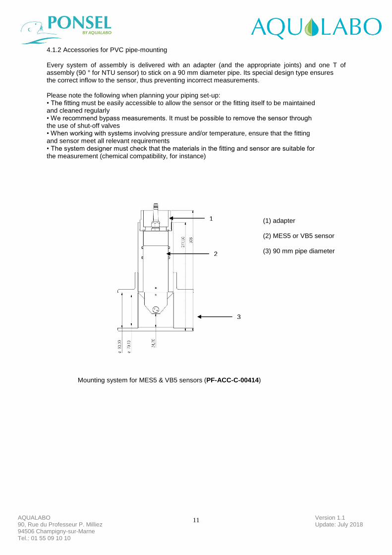
4.1.2 Accessories for PVC pipe-mounting Every system of assembly is delivered with an adapter (and the appropriate joints) and one T of assembly (90 ° for NTU sensor) to stick on a 90 mm diameter pipe. Its special design type ensures the correct inflow to the sensor, thus preventing incorrect measurements. Please note the following when planning your piping set-up: • The fitting must be easily accessible to allow the sensor or the fitting itself to be maintained and cleaned regularly • We recommend bypass measurements. It must be possible to remove the sensor through the use of shut-off valves • When working with systems involving pressure and/or temperature, ensure that the fitting and sensor meet all relevant requirements • The system designer must check that the materials in the fitting and sensor are suitable for the measurement (chemical compatibility, for instance)
Mounting system for MES5 & VB5 sensors (PF-ACC-C-00414)
1
2
3
(1) adapter (2) MES5 or VB5 sensor (3) 90 mm pipe diameter
12
Version 1.1 Update: July 2018
AQUALABO 90, Rue du Professeur P. Milliez 94506 Champigny-sur-Marne Tel.: 01 55 09 10 10
4.2 Installation of the sensor in the accessories of assembly
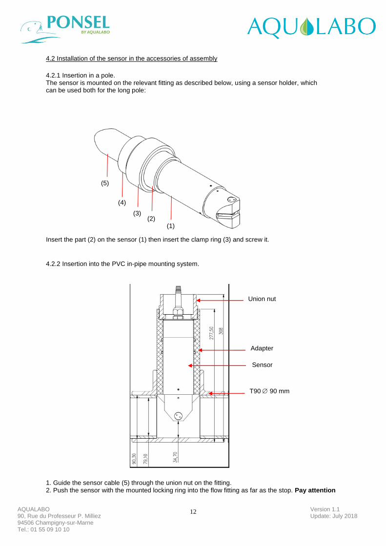
4.2.1 Insertion in a pole. The sensor is mounted on the relevant fitting as described below, using a sensor holder, which can be used both for the long pole: Insert the part (2) on the sensor (1) then insert the clamp ring (3) and screw it.
4.2.2 Insertion into the PVC in-pipe mounting system.
1. Guide the sensor cable (5) through the union nut on the fitting. 2. Push the sensor with the mounted locking ring into the flow fitting as far as the stop. Pay attention
(1) (2)
(3)
(4)
(3)
(5)
Union nut
Adapter
Sensor
T90 90 mm
13
Version 1.1 Update: July 2018
AQUALABO 90, Rue du Professeur P. Milliez 94506 Champigny-sur-Marne Tel.: 01 55 09 10 10
to the alignment of the sensor with regard to the flow.
3. Screw the union nut onto the fitting as far as the stop. 4.3 Electrical connections.
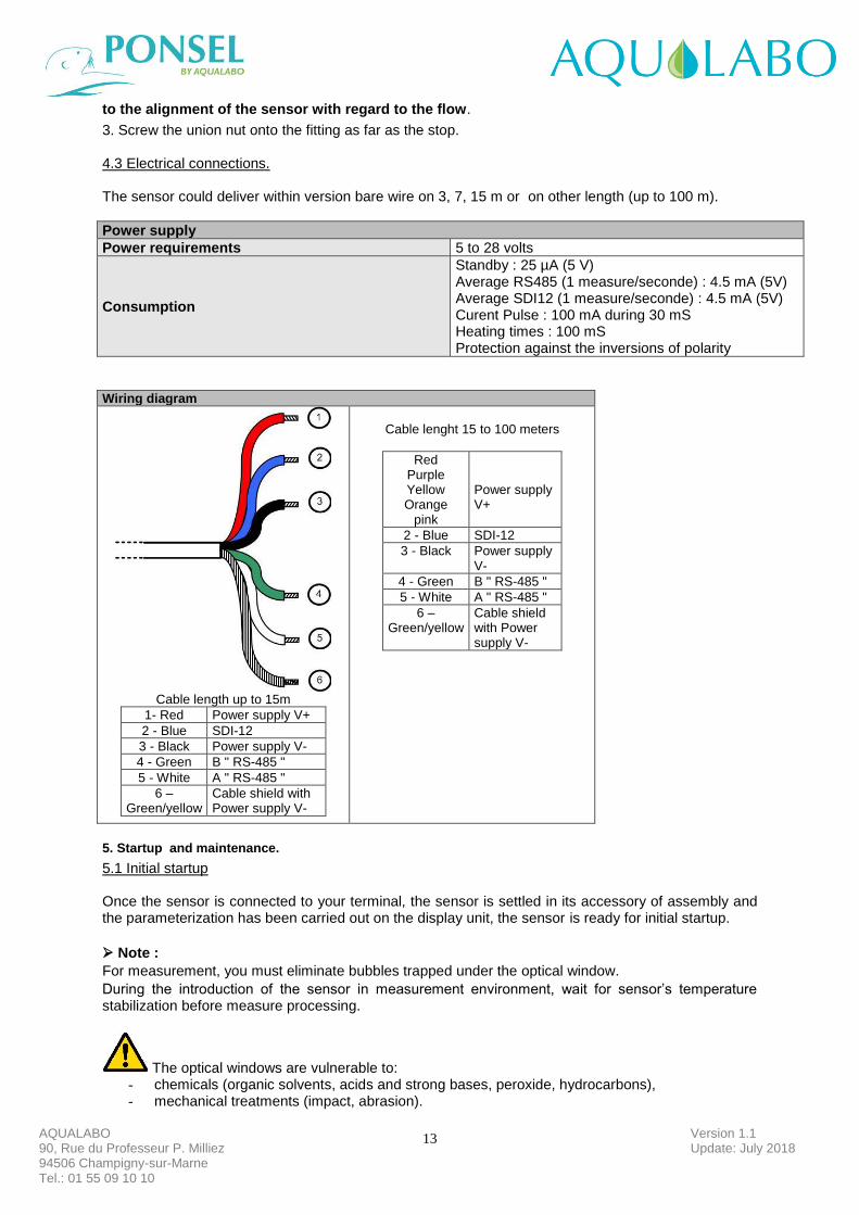
The sensor could deliver within version bare wire on 3, 7, 15 m or on other length (up to 100 m).
Power supply
Power requirements 5 to 28 volts
Consumption
Standby : 25 µA (5 V) Average RS485 (1 measure/seconde) : 4.5 mA (5V) Average SDI12 (1 measure/seconde) : 4.5 mA (5V) Curent Pulse : 100 mA during 30 mS Heating times : 100 mS Protection against the inversions of polarity
Wiring diagram
Cable length up to 15m
1- Red Power supply V+
2 - Blue SDI-12
3 - Black Power supply V-
4 - Green B " RS-485 "
5 - White A " RS-485 "
6 – Green/yellow
Cable shield with Power supply V-
Cable lenght 15 to 100 meters
Red Purple Yellow Orange
pink
Power supply V+
2 - Blue SDI-12
3 - Black Power supply V-
4 - Green B " RS-485 "
5 - White A " RS-485 "
6 – Green/yellow
Cable shield with Power supply V-
5. Startup and maintenance.
5.1 Initial startup
Once the sensor is connected to your terminal, the sensor is settled in its accessory of assembly and the parameterization has been carried out on the display unit, the sensor is ready for initial startup.
➢ Note :
For measurement, you must eliminate bubbles trapped under the optical window.
During the introduction of the sensor in measurement environment, wait for sensor’s temperature stabilization before measure processing.
The optical windows are vulnerable to: - chemicals (organic solvents, acids and strong bases, peroxide, hydrocarbons), - mechanical treatments (impact, abrasion).
14
Version 1.1 Update: July 2018
AQUALABO 90, Rue du Professeur P. Milliez 94506 Champigny-sur-Marne Tel.: 01 55 09 10 10
➢ Started : Remove the black cap of protection (by holding the sensor head downward and by unscrewing the hood towards the right).
5.2 Calibration
The method of two-point calibration for each of the four measuring ranges is available for calibrating the sensor. The sensor should be rinsed with clean water before each calibration. Organic deposits left on the sensor lens, such as a biofilm or silt, may cause measurement errors. These deposits should be removed carefully with warm soapy water and a soft sponge. Never use abrasive agents (e.g. scouring sponge). Calcium deposits can be removed by submersing the sensors in a diluted hydrochloric acid solution (concentration max. 5 %) for several minutes.
5.2.1.Calibration in NTU
The sensor is calibrated ex works, meaning that no calibration is required before initial startup. During operation, the sensor should be calibrated if the measured values begin to drift. If the zero point is moved, a complete two-point calibration must be carried out.
5.2.1.1 Offset calibration
The NTU sensor is an optical sensor which just need of a few calibration. On a clean sensor, check once in a while the 0 NTU value by dipping sensor in bubble free clear water. If the 0 point is shifted, proceed with the complete sensor calibration.
It is carried out as follows: • Immerse the sensor in distilled water (Attention on side effects, sensor has to be for a distance > 5 cm with regard to walls) in order to determine the zero point (offset). Wait that the sensor puts itself in equilibrium with the temperature of the standard solution. • Drying the sensor with a soft cloth or an absorbent paper.
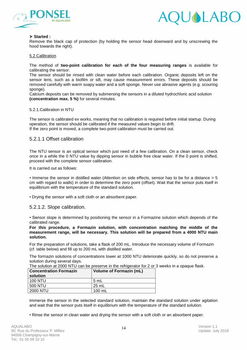
5.2.1.2. Slope calibration. • Sensor slope is determined by positioning the sensor in a Formazine solution which depends of the calibrated range.
For this procedure, a Formazin solution, with concentration matching the middle of the measurement range, will be necessary. This solution will be prepared from a 4000 NTU main solution.
For the preparation of solutions, take a flask of 200 mL. Introduce the necessary volume of Formazin (cf. table below) and fill up to 200 mL with distilled water.
The formazin solutions of concentrations lower at 1000 NTU deteriorate quickly, so do not preserve a solution during several days. The solution at 2000 NTU can be preserve in the refrigerator for 2 or 3 weeks in a opaque flask.
Concentration Formazin solution
Volume of Formazin (mL)
100 NTU 5 mL
500 NTU 25 mL
2000 NTU 100 mL
Immerse the sensor in the selected standard solution, maintain the standard solution under agitation and wait that the sensor puts itself in equilibrium with the temperature of the standard solution. • Rinse the sensor in clean water and drying the sensor with a soft cloth or an absorbent paper.
15
Version 1.1 Update: July 2018
AQUALABO 90, Rue du Professeur P. Milliez 94506 Champigny-sur-Marne Tel.: 01 55 09 10 10
5.2.2.Calibration in mg/L
5.2.2.1 Offset calibration
It is carried out as follows: • Immerse the sensor in distilled water (Attention on side effects, sensor has to be for a distance > 5 cm with regard to walls) in order to determine the zero point (offset). Wait that the sensor puts itself in equilibrium with the temperature of the standard solution. • Drying the sensor with a soft cloth or an absorbent paper.
5.2.2.2. Slope calibration. Turbidity in mg / L, it is necessary to calibrate the sensor on a real sample.
Immerse the sensor into a sample of sludge, maintained under agitation, and validate the theoretical value measured by the sensor. Analysis the sample dry weight in the laboratory according to the NF standard IN 872 for a range of 0-500 mg / L and according to the NF standard T 90 105 2 for a concentration > 500 mg / L. 5.3 Maintenance
The following points should be taken into account during ongoing operation of the sensor: • The sensor must always be kept clean, particularly in the area around the optical windows. The presence of deposits on the optical windows may lead to measurement errors. • Deposits such as a biofilm or silt should be removed carefully with warm soapy water and a soft sponge. Never use abrasive agents (e.g. scouring sponge). • If the sensor is put out of operation, it should be rinsed ready for storage, and the provided protective cap should be fitted.
16
Version 1.1 Update: July 2018
AQUALABO 90, Rue du Professeur P. Milliez 94506 Champigny-sur-Marne Tel.: 01 55 09 10 10
AQUALABO After-Sales Service
AQUALABO 115 Rue Michel MARION 56850 CAUDAN FRANCE Tel.: +33 (0) )5.62.75.95.70