Embed Size (px)
Citation preview
AQUAVAR® CPC - FD Variable Speed Drive with Fused DisconnectSUPPLEMENT TO THE INSTALLATION AND OPERATION MANUAL (IM167)
SUPPLEMENT MANUALIM250R02
2
SAFETYUse of Warnings and Notes ...................................................................................................................................................3
INSTALLATIONApplication ..............................................................................................................................................................................4
Input Disconnect Features and Functions ...........................................................................................................................4
Installation Flow Chart ............................................................................................................................................................6
Preparing for Installation (Supplement to Aquavar CPC-01/U1 User’s Manual) .............................................................7
Installing the Drive (Supplement to Aquavar CPC-01/U1 User’s Manual) .......................................................................9
Installing the Wiring (Supplement to Aquavar CPC-01/U1 User’s Manual) ................................................................. 10
MAINTENANCEMaintenance Intervals ......................................................................................................................................................... 14
Drive Module Fan Replacement ........................................................................................................................................ 14
Enclosure Fan Replacement – NEMA 12 Enclosures ....................................................................................................... 15
Enclosure Air Filter Replacement – NEMA 12 Enclosures............................................................................................... 16
TECHNICAL DATARatings (Supplement to Aquavar CPC-01/U1 User’s Manual) ........................................................................................ 19
Input Power Connections (Supplement to Aquavar CPC-01/U1 User’s Manual) ........................................................ 20
Motor Connections .............................................................................................................................................................. 26
Cooling – R7/R8 .................................................................................................................................................................... 26
Dimensions and Weights (Supplement to Aquavar CPC-01/U1 User’s Manual) ......................................................... 27
Applicable Standards .......................................................................................................................................................... 34
INDEX
TABLE OF CONTENTS
3
WARNING! The AQUAVAR CPC adjustable speed AC drive with Input Disconnect should ONLY be installed by a qualified electrician.
WARNING! Even when the motor is stopped, dangerous voltage is present at the Power Circuit terminals U1, V1, W1 and U2, V2, W2 and, depending on the frame size, UDC+ and UDC-, or BRK+ and BRK-.
WARNING! Dangerous voltage is present when input power is connected. After disconnecting the supply, wait at least 5 minutes (to let the intermediate circuit capacitors discharge) before removing the cover.
WARNING! Even when power is removed from the input terminals of the AQUAVAR CPC, there may be dangerous voltage (from external sources) on the terminals of the relay outputs.
WARNING! When the control terminals of two or more drive units are connected in parallel, the auxiliary voltage for these control connections must be taken from a single source which can either be one of the units or an external supply.
WARNING! The AQUAVAR CPC will start up automatically after an input voltage interruption if the external run command is on.
WARNING! When the AQUAVAR CPC with Input Disconnect is connected to the line power, the Motor Terminals T1, T2 and T3 are live even if the motor is not running. Do not make any connections when the AQUAVAR CPC with Input Disconnect is connected to the line. Disconnect and lock out power to the drive before servicing the drive. Failure to disconnect power may cause serious injury or death.
NOTE! For more technical information, contact the factory or your local AQUAVAR representative.
USE OF WARNINGS AND NOTES
There are two types of safety instructions throughout this manual:
• Notes draw attention to a particular condition or fact, or give information on a subject.
• Warnings caution you about conditions which can result in serious injury or death and/or damage to the equipment. They also tell you how to avoid the danger. The warning symbols are used as follows:
DANGEROUS VOLTAGE WARNING warns of high voltage which can cause physical injury and/or damage to the equipment.
GENERAL WARNING warns about conditions, other than those caused by electricity, which can result in physical injury and/or damage to the equipment.
SAFETY
4
Study these installation instructions carefully before proceeding. Failure to observe the warn-ings and instructions may cause a malfunction or personal hazard.
WARNING! Before you begin read “Safety” on page 3.
WARNING! When the Aquavar CPC with Input Disconnect is connected to the line power, the Motor Terminals T1, T2, and T3 are live even if the motor is not running. Do not make any connections when the Aquavar CPC with Input Disconnect is connected to the line. Disconnect and lock out power to the drive before servicing the drive. Fail-ure to disconnect power may cause serious injury or death.
ApplicationThis manual contains supplemental information that is unique to Aquavar CPC input dis-connect configurations (“FD” suffix). Refer to the base manual, Aquavar CPC User’s Manual (IM167), for all other information.
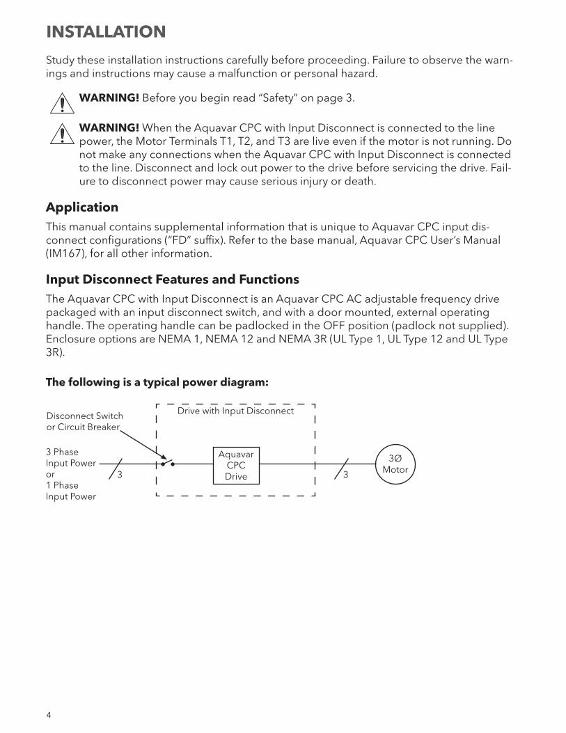
Input Disconnect Features and FunctionsThe Aquavar CPC with Input Disconnect is an Aquavar CPC AC adjustable frequency drive packaged with an input disconnect switch, and with a door mounted, external operating handle. The operating handle can be padlocked in the OFF position (padlock not supplied). Enclosure options are NEMA 1, NEMA 12 and NEMA 3R (UL Type 1, UL Type 12 and UL Type 3R).
The following is a typical power diagram:
Aquavar CPC Drive
3ØMotor3
Drive with Input DisconnectDisconnect Switch or Circuit Breaker
3
3 PhaseInput Poweror1 PhaseInput Power
INSTALLATION
5
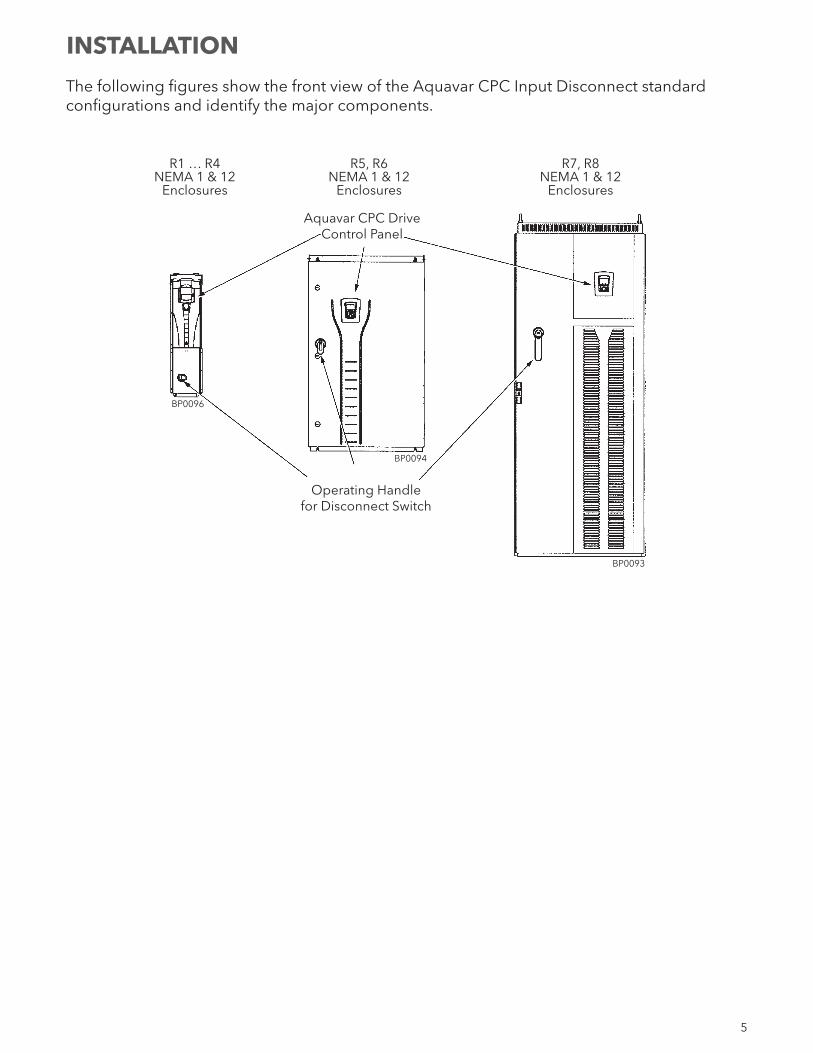
The following figures show the front view of the Aquavar CPC Input Disconnect standard configurations and identify the major components.
R1 … R4 R5, R6 R7, R8 NEMA 1 & 12 NEMA 1 & 12 NEMA 1 & 12 Enclosures Enclosures Enclosures
Aquavar CPC DriveControl Panel
Operating Handlefor Disconnect Switch
BP0096
BP0094
BP0093
INSTALLATION
6
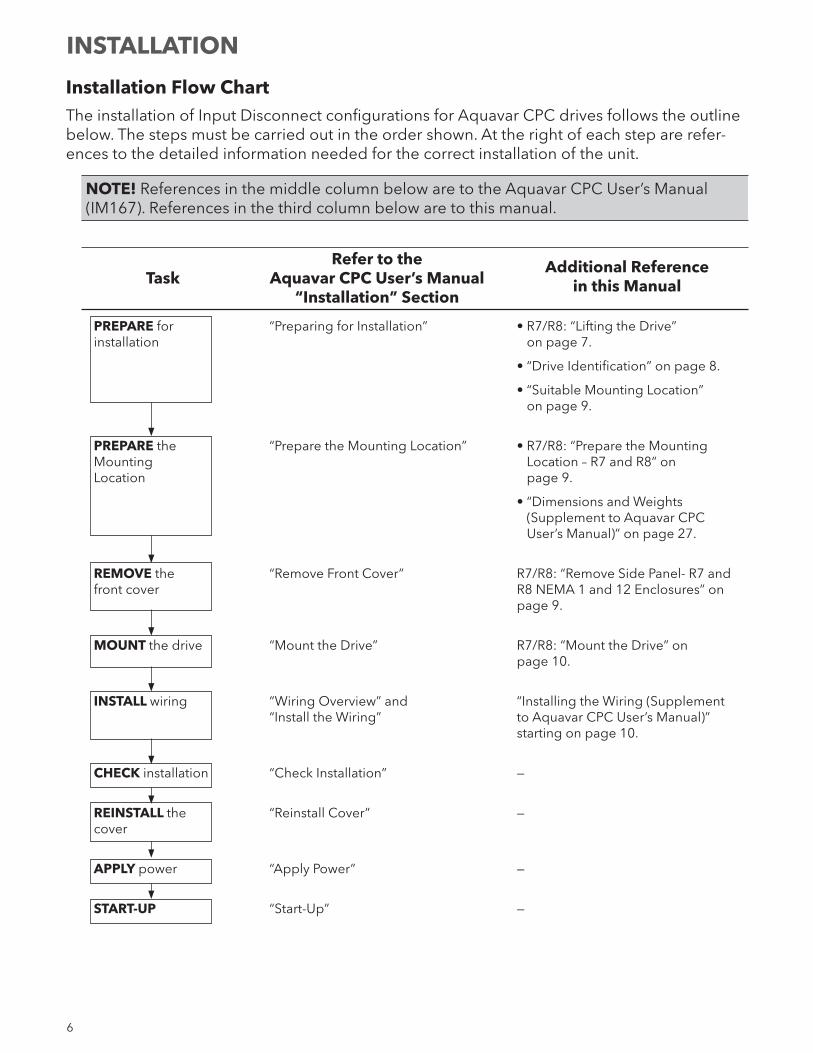
Installation Flow ChartThe installation of Input Disconnect configurations for Aquavar CPC drives follows the outline below. The steps must be carried out in the order shown. At the right of each step are refer-ences to the detailed information needed for the correct installation of the unit.
NOTE! References in the middle column below are to the Aquavar CPC User’s Manual (IM167). References in the third column below are to this manual.
Refer to the Additional Reference Task Aquavar CPC User’s Manual in this Manual “Installation” Section
PREPARE for “Preparing for Installation” • R7/R8: “Lifting the Drive” installation on page 7.
• “Drive Identification” on page 8.
• “Suitable Mounting Location” on page 9.
PREPARE the “Prepare the Mounting Location” • R7/R8: “Prepare the Mounting Mounting Location – R7 and R8” on Location page 9.
• “Dimensions and Weights (Supplement to Aquavar CPC User’s Manual)” on page 27.
REMOVE the “Remove Front Cover” R7/R8: “Remove Side Panel- R7 and front cover R8 NEMA 1 and 12 Enclosures” on page 9.
MOUNT the drive “Mount the Drive” R7/R8: “Mount the Drive” on page 10.
INSTALL wiring “Wiring Overview” and “Installing the Wiring (Supplement “Install the Wiring” to Aquavar CPC User’s Manual)” starting on page 10.
CHECK installation “Check Installation” —
REINSTALL the “Reinstall Cover” — cover
APPLY power “Apply Power” —
START-UP “Start-Up” —
INSTALLATION
7
Preparing for Installation (Supplement to Aquavar CPC User’s Manual)
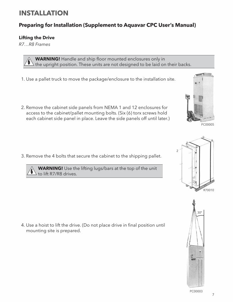
Lifting the DriveR7…R8 Frames
WARNING! Handle and ship floor mounted enclosures only in the upright position. These units are not designed to be laid on their backs.
1. Use a pallet truck to move the package/enclosure to the installation site.
2. Remove the cabinet side panels from NEMA 1 and 12 enclosures for access to the cabinet/pallet mounting bolts. (Six (6) torx screws hold each cabinet side panel in place. Leave the side panels off until later.)
3. Remove the 4 bolts that secure the cabinet to the shipping pallet.
WARNING! Use the lifting lugs/bars at the top of the unit to lift R7/R8 drives.
4. Use a hoist to lift the drive. (Do not place drive in final position until mounting site is prepared.
PC00005
R70010
2
PC00003
30º
INSTALLATION
8
Preparing for Installation (Supplement to Aquavar CPC User’s Manual)Drive IdentificationTo identify the type of device you are installing, refer to the type code number on the device identification label.
• Wall mounting base drives – label attached on the side surface of the heat sink.• Packaged drive with screw cover – label attached to outside surface on the left ide of the
enclosure.• Enclosure with hinged cover/door – label on inside surface of the cover/door.
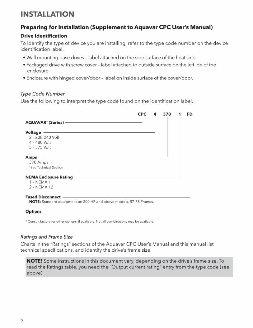
Type Code NumberUse the following to interpret the type code found on the identification label.
CPC 4 370 1 FD
AQUAVAR® (Series)
Voltage 2 – 208-240 Volt 4 – 480 Volt 5 – 575 Volt
Amps 370 Amps *See Technical Section
NEMA Enclosure Rating 1 – NEMA 1 2 – NEMA 12
Fused Disconnect NOTE: Standard equipment on 200 HP and above models, R7-R8 Frames.
Options
* Consult factory for other options, if available. Not all combinations may be available.
Ratings and Frame SizeCharts in the “Ratings” sections of the Aquavar CPC User’s Manual and this manual list technical specifications, and identify the drive’s frame size.
NOTE! Some instructions in this document vary, depending on the drive’s frame size. To read the Ratings table, you need the “Output current rating” entry from the type code (see above).
INSTALLATION
9
Suitable Mounting LocationFor selecting a suitable mounting location for FD configurations, refer to:
• Preparing for installation in the Aquavar CPC User’s Manual, and• The Technical Data section of this manual for information on dimensions and weights.
Installing the Drive (Supplement to Aquavar CPC User’s Manual - IM167)
WARNING! Metal shavings or debris in the enclosure can damage electrical equipment and create a hazardous condition. Where parts, such as conduit plates
require cutting or drilling, first remove the part. If that is not practical, cover nearby electrical components to protect them from all shavings or debris.
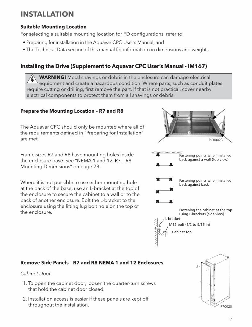
Prepare the Mounting Location – R7 and R8
The Aquavar CPC should only be mounted where all of the requirements defined in “Preparing for Installation” are met.
Frame sizes R7 and R8 have mounting holes inside the enclosure base. See “NEMA 1 and 12, R7…R8 Mounting Dimensions” on page 28.
Where it is not possible to use either mounting hole at the back of the base, use an L-bracket at the top of the enclosure to secure the cabinet to a wall or to the back of another enclosure. Bolt the L-bracket to the enclosure using the lifting lug bolt hole on the top of the enclosure.
Remove Side Panels – R7 and R8 NEMA 1 and 12 Enclosures
Cabinet Door
1. To open the cabinet door, loosen the quarter-turn screws that hold the cabinet door closed.
2. Installation access is easier if these panels are kept off throughout the installation.
PC00023
Fastening points when installedback against a wall (top view)
Fastening points when installedback against back
Fastening the cabinet at the topusing L-brackets (side view)
L-bracket
M12 bolt (1/2 to 9/16 in)
Cabinet top
INSTALLATION
R70020
2
10
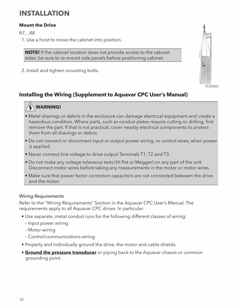
Mount the Drive
R7…R81. Use a hoist to move the cabinet into position.
NOTE! If the cabinet location does not provide access to the cabinet sides, be sure to re-mount side panels before positioning cabinet.
2. Install and tighten mounting bolts.
Installing the Wiring (Supplement to Aquavar CPC User’s Manual)
WARNING!
• Metal shavings or debris in the enclosure can damage electrical equipment and create a hazardous condition. Where parts, such as conduit plates require cutting or drilling, first remove the part. If that is not practical, cover nearby electrical components to protect them from all shavings or debris.
• Do not connect or disconnect input or output power wiring, or control wires, when power is applied.
• Never connect line voltage to drive output Terminals T1, T2 and T3.
• Do not make any voltage tolerance tests (Hi Pot or Megger) on any part of the unit. Disconnect motor wires before taking any measurements in the motor or motor wires.
• Make sure that power factor correction capacitors are not connected between the drive and the motor.
Wiring RequirementsRefer to the “Wiring Requirements” Section in the Aquavar CPC User’s Manual. The requirements apply to all Aquavar CPC drives. In particular:
• Use separate, metal conduit runs for the following different classes of wiring:– Input power wiring– Motor wiring– Control/communications wiring
• Properly and individually ground the drive, the motor and cable shields.
• Ground the pressure transducer or piping back to the Aquavar chassis or common grounding point.
PC00003
30º
INSTALLATION
11
Wiring Overview
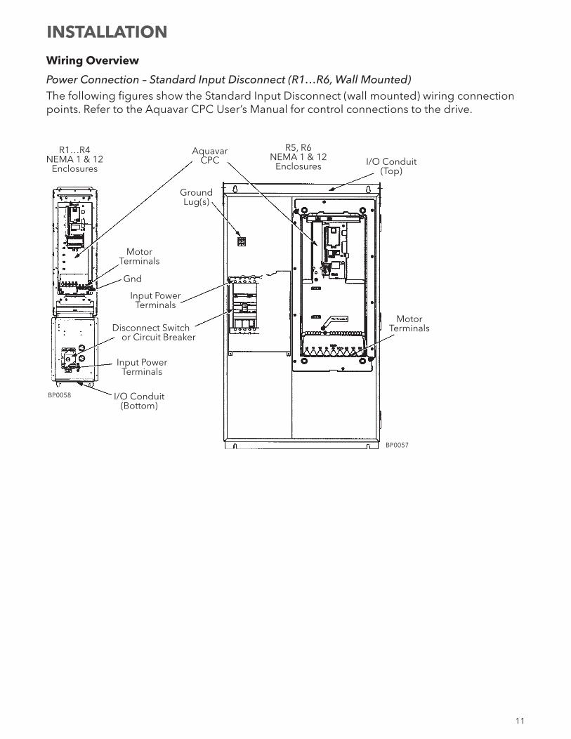
Power Connection – Standard Input Disconnect (R1…R6, Wall Mounted)The following figures show the Standard Input Disconnect (wall mounted) wiring connection points. Refer to the Aquavar CPC User’s Manual for control connections to the drive.
INSTALLATION
R1…R4NEMA 1 & 12
Enclosures
Aquavar CPC
R5, R6NEMA 1 & 12
Enclosures I/O Conduit(Top)
MotorTerminals
GroundLug(s)
MotorTerminals
Gnd
Input PowerTerminals
Input PowerTerminals
I/O Conduit(Bottom)
BP0058
Disconnect Switchor Circuit Breaker
BP0057
12
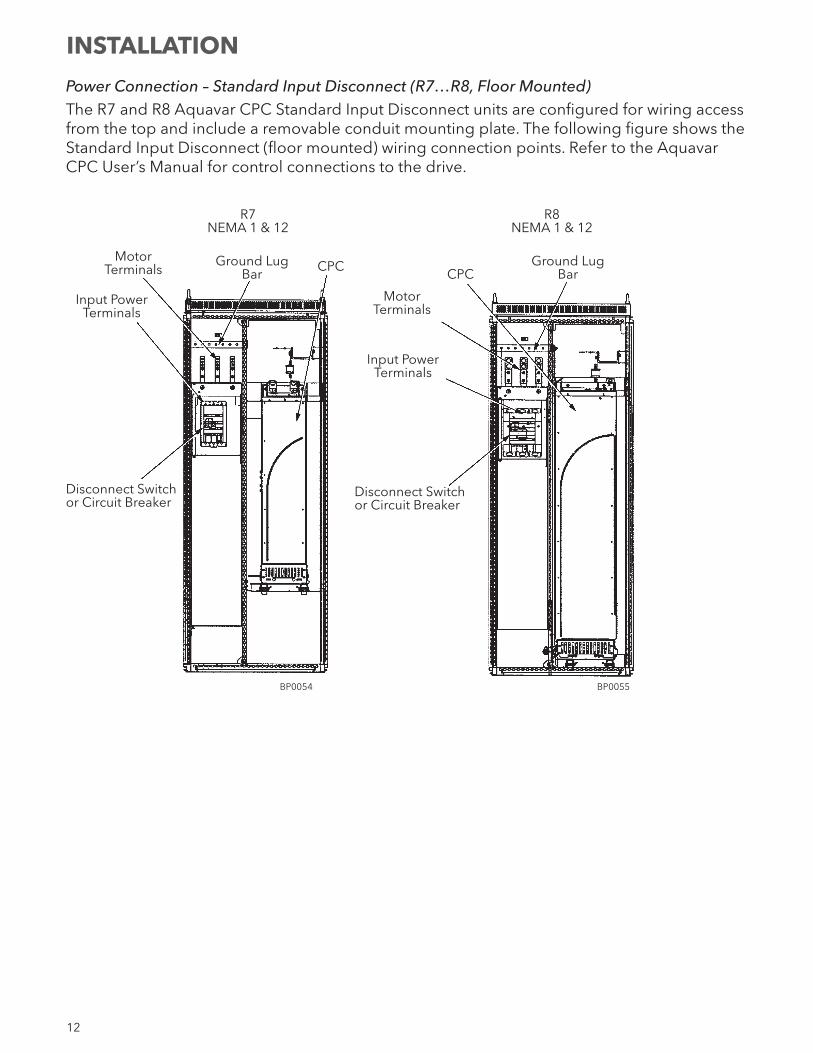
Power Connection – Standard Input Disconnect (R7…R8, Floor Mounted)The R7 and R8 Aquavar CPC Standard Input Disconnect units are configured for wiring access from the top and include a removable conduit mounting plate. The following figure shows the Standard Input Disconnect (floor mounted) wiring connection points. Refer to the Aquavar CPC User’s Manual for control connections to the drive.
R7NEMA 1 & 12
MotorTerminals
Input PowerTerminals
Disconnect Switchor Circuit Breaker
CPC
BP0054 BP0055
Disconnect Switchor Circuit Breaker
Input PowerTerminals
MotorTerminals
CPC
R8NEMA 1 & 12
Ground LugBar
Ground LugBar
INSTALLATION
13
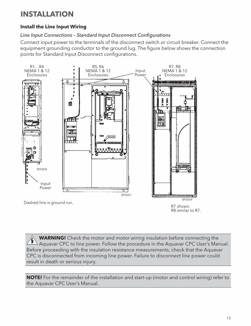
Install the Line Input Wiring
Line Input Connections – Standard Input Disconnect ConfigurationsConnect input power to the terminals of the disconnect switch or circuit breaker. Connect the equipment grounding conductor to the ground lug. The figure below shows the connection points for Standard Input Disconnect configurations.
WARNING! Check the motor and motor wiring insulation before connecting the Aquavar CPC to line power. Follow the procedure in the Aquavar CPC User’s Manual.
Before proceeding with the insulation resistance measurements, check that the Aquavar CPC is disconnected from incoming line power. Failure to disconnect line power could result in death or serious injury.
NOTE! For the remainder of the installation and start-up (motor and control wiring) refer to the Aquavar CPC User’s Manual.
INSTALLATION
R1…R4NEMA 1 & 12
Enclosures
R5, R6NEMA 1 & 12
EnclosuresInput Power
BP0058
R7, R8NEMA 1 & 12
Enclosures
Input Power
BP0057
BP0054Dashed line is ground run.
R7 shown.R8 similar to R7.
14
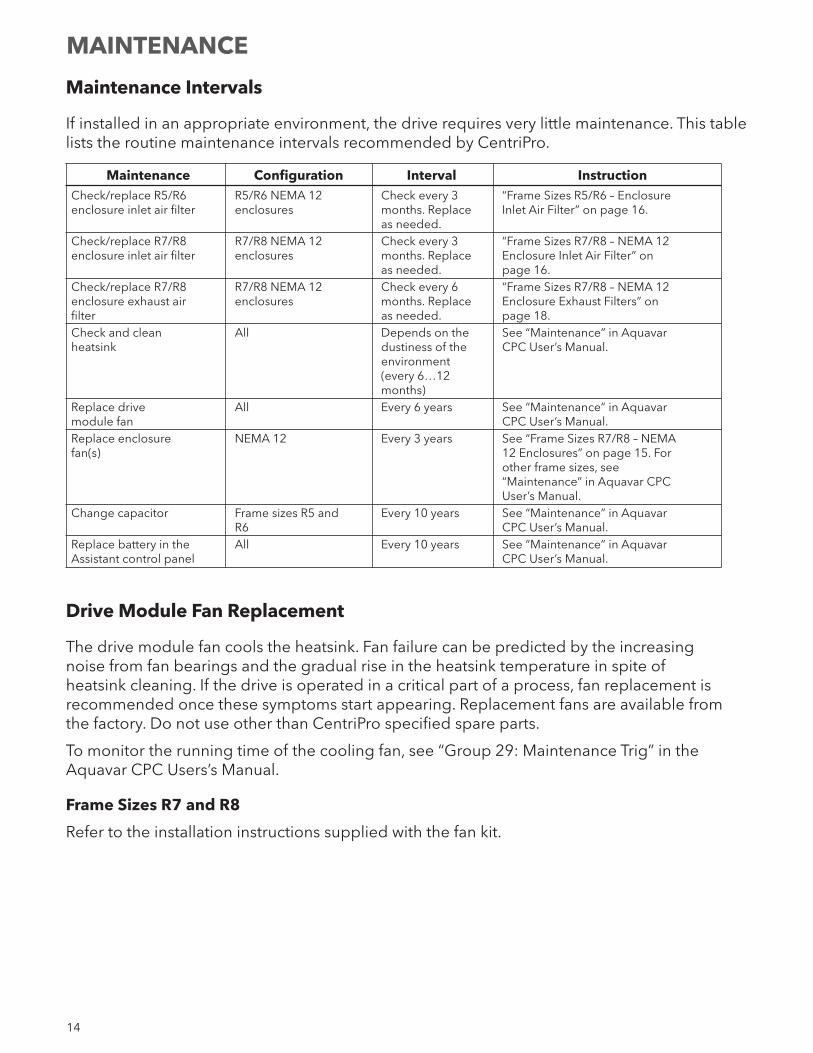
Maintenance Intervals
If installed in an appropriate environment, the drive requires very little maintenance. This table lists the routine maintenance intervals recommended by CentriPro.
Maintenance Configuration Interval Instruction Check/replace R5/R6 R5/R6 NEMA 12 Check every 3 “Frame Sizes R5/R6 – Enclosure enclosure inlet air filter enclosures months. Replace Inlet Air Filter” on page 16. as needed. Check/replace R7/R8 R7/R8 NEMA 12 Check every 3 “Frame Sizes R7/R8 – NEMA 12 enclosure inlet air filter enclosures months. Replace Enclosure Inlet Air Filter” on as needed. page 16. Check/replace R7/R8 R7/R8 NEMA 12 Check every 6 “Frame Sizes R7/R8 – NEMA 12 enclosure exhaust air enclosures months. Replace Enclosure Exhaust Filters” on filter as needed. page 18. Check and clean All Depends on the See “Maintenance” in Aquavar heatsink dustiness of the CPC User’s Manual. environment (every 6…12 months) Replace drive All Every 6 years See “Maintenance” in Aquavar module fan CPC User’s Manual. Replace enclosure NEMA 12 Every 3 years See “Frame Sizes R7/R8 – NEMA fan(s) 12 Enclosures” on page 15. For other frame sizes, see “Maintenance” in Aquavar CPC User’s Manual. Change capacitor Frame sizes R5 and Every 10 years See “Maintenance” in Aquavar R6 CPC User’s Manual. Replace battery in the All Every 10 years See “Maintenance” in Aquavar Assistant control panel CPC User’s Manual.
Drive Module Fan Replacement
The drive module fan cools the heatsink. Fan failure can be predicted by the increasing noise from fan bearings and the gradual rise in the heatsink temperature in spite of heatsink cleaning. If the drive is operated in a critical part of a process, fan replacement is recommended once these symptoms start appearing. Replacement fans are available from the factory. Do not use other than CentriPro specified spare parts.
To monitor the running time of the cooling fan, see “Group 29: Maintenance Trig” in the Aquavar CPC Users’s Manual.
Frame Sizes R7 and R8
Refer to the installation instructions supplied with the fan kit.
MAINTENANCE
15
PC00021
PC00018
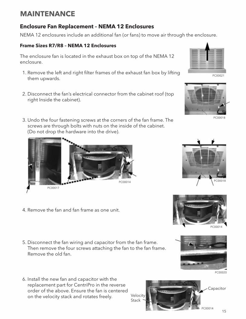
Enclosure Fan Replacement – NEMA 12 EnclosuresNEMA 12 enclosures include an additional fan (or fans) to move air through the enclosure.
Frame Sizes R7/R8 – NEMA 12 Enclosures
The enclosure fan is located in the exhaust box on top of the NEMA 12 enclosure.
1. Remove the left and right filter frames of the exhaust fan box by lifting them upwards.
2. Disconnect the fan’s electrical connector from the cabinet roof (top right Inside the cabinet).
3. Undo the four fastening screws at the corners of the fan frame. The screws are through bolts with nuts on the inside of the cabinet. (Do not drop the hardware into the drive).
4. Remove the fan and fan frame as one unit.
5. Disconnect the fan wiring and capacitor from the fan frame. Then remove the four screws attaching the fan to the fan frame. Remove the old fan.
6. Install the new fan and capacitor with the replacement part for CentriPro in the reverse order of the above. Ensure the fan is centered on the velocity stack and rotates freely.
PC00018PC00014
PC00017
PC00014
MAINTENANCE
PC00020
Capacitor
PC00014
Velocity Stack
16
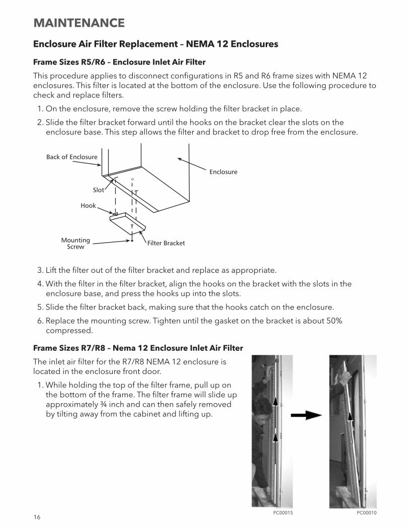
Enclosure Air Filter Replacement – NEMA 12 Enclosures
Frame Sizes R5/R6 – Enclosure Inlet Air Filter
This procedure applies to disconnect configurations in R5 and R6 frame sizes with NEMA 12 enclosures. This filter is located at the bottom of the enclosure. Use the following procedure to check and replace filters.
1. On the enclosure, remove the screw holding the filter bracket in place.
2. Slide the filter bracket forward until the hooks on the bracket clear the slots on the enclosure base. This step allows the filter and bracket to drop free from the enclosure.
3. Lift the filter out of the filter bracket and replace as appropriate.
4. With the filter in the filter bracket, align the hooks on the bracket with the slots in the enclosure base, and press the hooks up into the slots.
5. Slide the filter bracket back, making sure that the hooks catch on the enclosure.
6. Replace the mounting screw. Tighten until the gasket on the bracket is about 50% compressed.
Frame Sizes R7/R8 – Nema 12 Enclosure Inlet Air Filter
The inlet air filter for the R7/R8 NEMA 12 enclosure is located in the enclosure front door.
1. While holding the top of the filter frame, pull up on the bottom of the frame. The filter frame will slide up approximately ¾ inch and can then safely removed by tilting away from the cabinet and lifting up.
Back of Enclosure
Slot
Hook
MountingScrew Filter Bracket
Enclosure
MAINTENANCE
PC00010PC00015
17
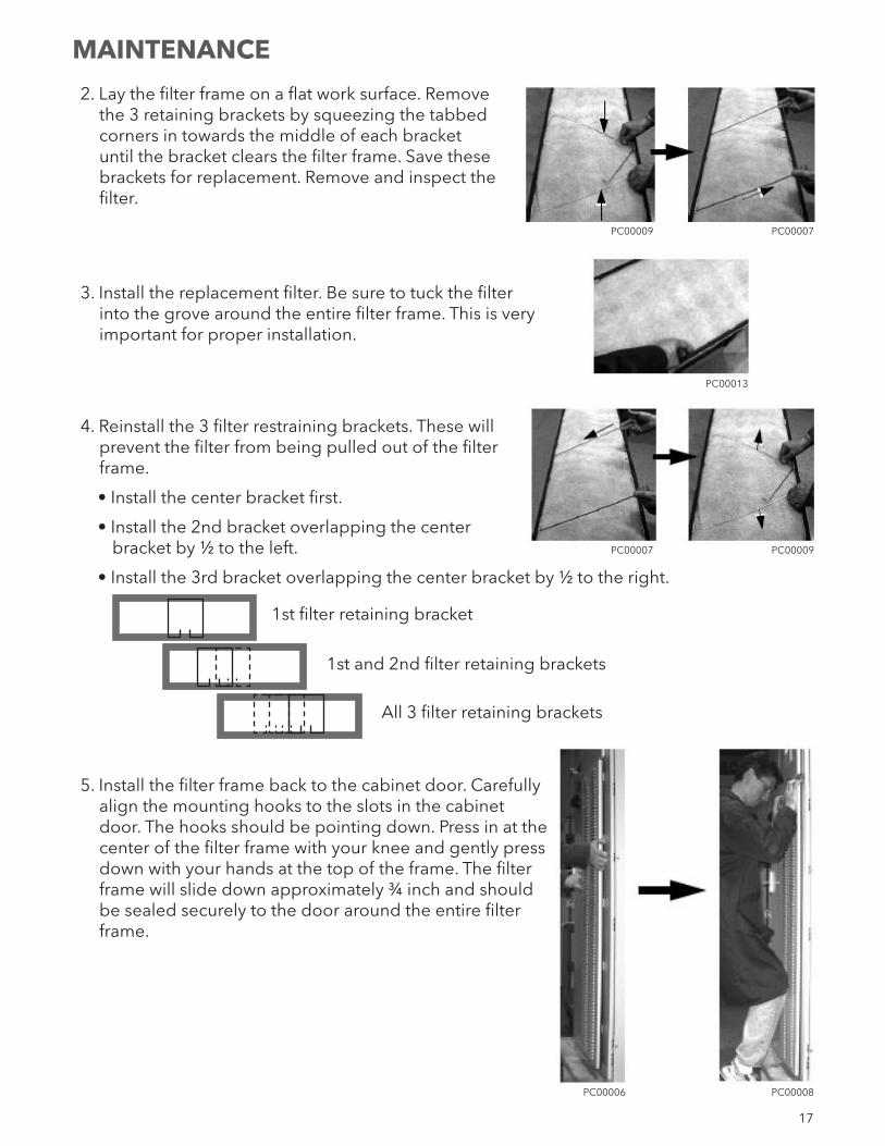
2. Lay the filter frame on a flat work surface. Remove the 3 retaining brackets by squeezing the tabbed corners in towards the middle of each bracket until the bracket clears the filter frame. Save these brackets for replacement. Remove and inspect the filter.
3. Install the replacement filter. Be sure to tuck the filter into the grove around the entire filter frame. This is very important for proper installation.
4. Reinstall the 3 filter restraining brackets. These will prevent the filter from being pulled out of the filter frame.
• Install the center bracket first.
• Install the 2nd bracket overlapping the center bracket by ½ to the left.
• Install the 3rd bracket overlapping the center bracket by ½ to the right.
1st filter retaining bracket
1st and 2nd filter retaining brackets
All 3 filter retaining brackets
5. Install the filter frame back to the cabinet door. Carefully align the mounting hooks to the slots in the cabinet door. The hooks should be pointing down. Press in at the center of the filter frame with your knee and gently press down with your hands at the top of the frame. The filter frame will slide down approximately ¾ inch and should be sealed securely to the door around the entire filter frame.
PC00009 PC00007
PC00007 PC00009
PC00013
MAINTENANCE
PC00008PC00006
18
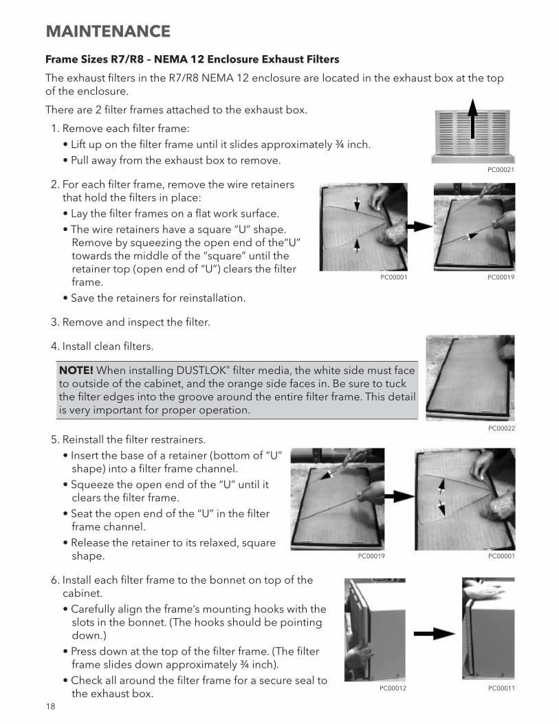
Frame Sizes R7/R8 – NEMA 12 Enclosure Exhaust Filters
The exhaust filters in the R7/R8 NEMA 12 enclosure are located in the exhaust box at the top of the enclosure.
There are 2 filter frames attached to the exhaust box.
1. Remove each filter frame:• Lift up on the filter frame until it slides approximately ¾ inch.• Pull away from the exhaust box to remove.
2. For each filter frame, remove the wire retainers that hold the filters in place:• Lay the filter frames on a flat work surface.• The wire retainers have a square “U” shape.
Remove by squeezing the open end of the“U” towards the middle of the “square” until the retainer top (open end of “U”) clears the filter frame.
• Save the retainers for reinstallation.
3. Remove and inspect the filter.
4. Install clean filters.
NOTE! When installing DUSTLOK® filter media, the white side must face to outside of the cabinet, and the orange side faces in. Be sure to tuck the filter edges into the groove around the entire filter frame. This detail is very important for proper operation.
5. Reinstall the filter restrainers.• Insert the base of a retainer (bottom of “U”
shape) into a filter frame channel.• Squeeze the open end of the “U” until it
clears the filter frame.• Seat the open end of the “U” in the filter
frame channel.• Release the retainer to its relaxed, square
shape.
6. Install each filter frame to the bonnet on top of the cabinet.• Carefully align the frame’s mounting hooks with the
slots in the bonnet. (The hooks should be pointing down.)
• Press down at the top of the filter frame. (The filter frame slides down approximately ¾ inch).
• Check all around the filter frame for a secure seal to the exhaust box.
PC00021
PC00001 PC00019
MAINTENANCE
PC00022
PC00001PC00019
PC00011PC00012
19
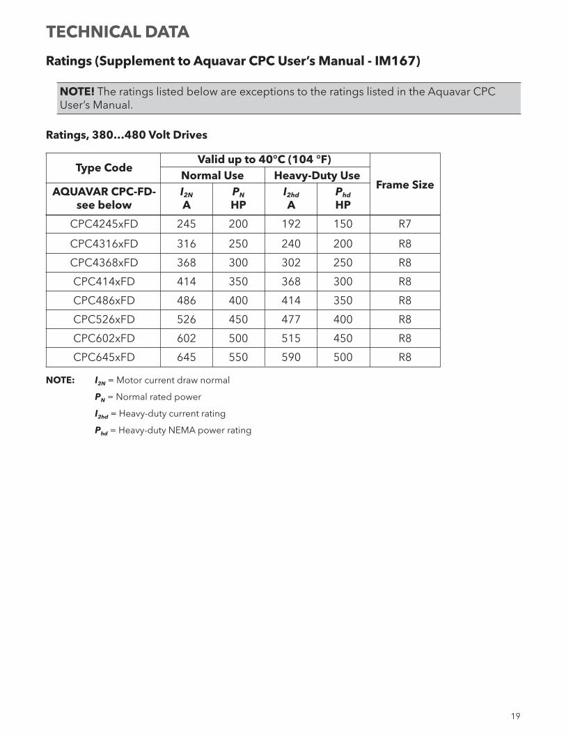
Ratings (Supplement to Aquavar CPC User’s Manual - IM167)
NOTE! The ratings listed below are exceptions to the ratings listed in the Aquavar CPC User’s Manual.
Ratings, 380…480 Volt Drives
Type Code
Valid up to 40°C (104 °F) Normal Use Heavy-Duty Use
Frame Size AQUAVAR CPC-FD- I2N PN I2hd Phd
see below A HP A HP
CPC4245xFD 245 200 192 150 R7
CPC4316xFD 316 250 240 200 R8
CPC4368xFD 368 300 302 250 R8
CPC414xFD 414 350 368 300 R8
CPC486xFD 486 400 414 350 R8
CPC526xFD 526 450 477 400 R8
CPC602xFD 602 500 515 450 R8
CPC645xFD 645 550 590 500 R8
NOTE: I2N = Motor current draw normal
PN = Normal rated power
I2hd = Heavy-duty current rating
Phd = Heavy-duty NEMA power rating
TECHNICAL DATA
20
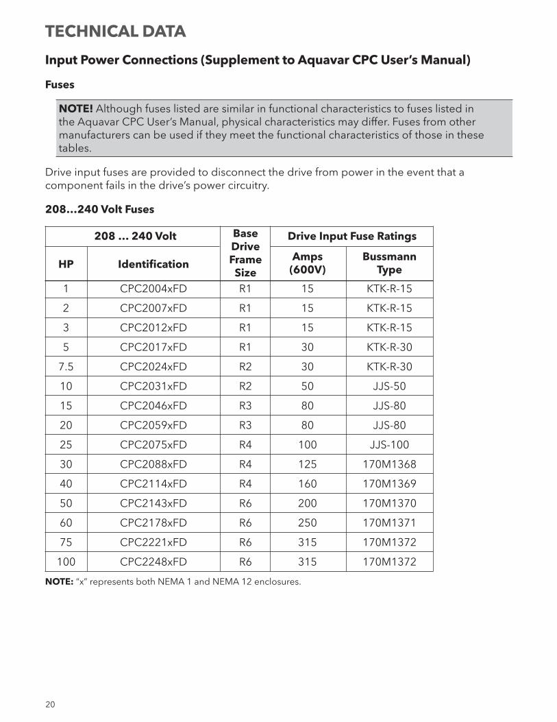
Input Power Connections (Supplement to Aquavar CPC User’s Manual)
Fuses
NOTE! Although fuses listed are similar in functional characteristics to fuses listed in the Aquavar CPC User’s Manual, physical characteristics may differ. Fuses from other manufacturers can be used if they meet the functional characteristics of those in these tables.
Drive input fuses are provided to disconnect the drive from power in the event that a component fails in the drive’s power circuitry.
208…240 Volt Fuses
208 … 240 Volt Base Drive Input Fuse Ratings Drive
Amps Bussmann HP Identification Frame (600V) Type Size
1 CPC2004xFD R1 15 KTK-R-15
2 CPC2007xFD R1 15 KTK-R-15
3 CPC2012xFD R1 15 KTK-R-15
5 CPC2017xFD R1 30 KTK-R-30
7.5 CPC2024xFD R2 30 KTK-R-30
10 CPC2031xFD R2 50 JJS-50
15 CPC2046xFD R3 80 JJS-80
20 CPC2059xFD R3 80 JJS-80
25 CPC2075xFD R4 100 JJS-100
30 CPC2088xFD R4 125 170M1368
40 CPC2114xFD R4 160 170M1369
50 CPC2143xFD R6 200 170M1370
60 CPC2178xFD R6 250 170M1371
75 CPC2221xFD R6 315 170M1372
100 CPC2248xFD R6 315 170M1372
NOTE: “x” represents both NEMA 1 and NEMA 12 enclosures.
TECHNICAL DATA
21
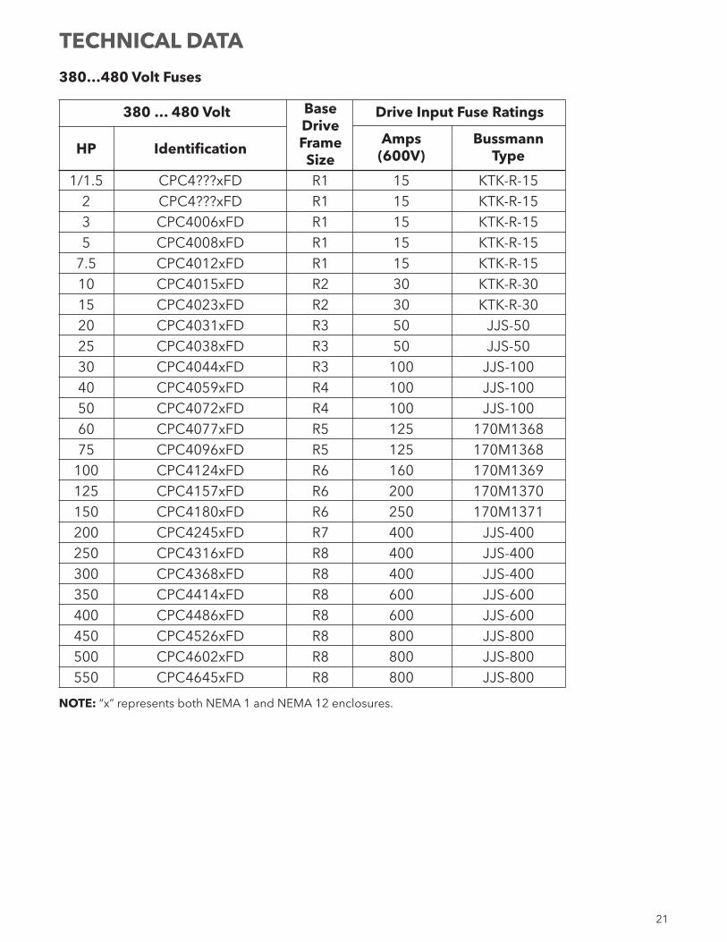
380…480 Volt Fuses
380 … 480 Volt Base Drive Input Fuse Ratings Drive
Amps Bussmann HP Identification Frame (600V) Type Size
1/1.5 CPC4???xFD R1 15 KTK-R-15 2 CPC4???xFD R1 15 KTK-R-15 3 CPC4006xFD R1 15 KTK-R-15 5 CPC4008xFD R1 15 KTK-R-15 7.5 CPC4012xFD R1 15 KTK-R-15 10 CPC4015xFD R2 30 KTK-R-30 15 CPC4023xFD R2 30 KTK-R-30 20 CPC4031xFD R3 50 JJS-50 25 CPC4038xFD R3 50 JJS-50 30 CPC4044xFD R3 100 JJS-100 40 CPC4059xFD R4 100 JJS-100 50 CPC4072xFD R4 100 JJS-100 60 CPC4077xFD R5 125 170M1368 75 CPC4096xFD R5 125 170M1368 100 CPC4124xFD R6 160 170M1369 125 CPC4157xFD R6 200 170M1370 150 CPC4180xFD R6 250 170M1371 200 CPC4245xFD R7 400 JJS-400 250 CPC4316xFD R8 400 JJS-400 300 CPC4368xFD R8 400 JJS-400 350 CPC4414xFD R8 600 JJS-600 400 CPC4486xFD R8 600 JJS-600 450 CPC4526xFD R8 800 JJS-800 500 CPC4602xFD R8 800 JJS-800 550 CPC4645xFD R8 800 JJS-800
NOTE: “x” represents both NEMA 1 and NEMA 12 enclosures.
TECHNICAL DATA
22
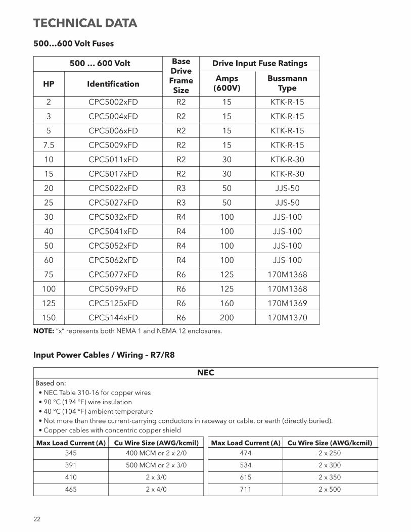
500…600 Volt Fuses
500 … 600 Volt Base Drive Input Fuse Ratings Drive
Amps Bussmann HP Identification Frame (600V) Type Size
2 CPC5002xFD R2 15 KTK-R-15
3 CPC5004xFD R2 15 KTK-R-15
5 CPC5006xFD R2 15 KTK-R-15
7.5 CPC5009xFD R2 15 KTK-R-15
10 CPC5011xFD R2 30 KTK-R-30
15 CPC5017xFD R2 30 KTK-R-30
20 CPC5022xFD R3 50 JJS-50
25 CPC5027xFD R3 50 JJS-50
30 CPC5032xFD R4 100 JJS-100
40 CPC5041xFD R4 100 JJS-100
50 CPC5052xFD R4 100 JJS-100
60 CPC5062xFD R4 100 JJS-100
75 CPC5077xFD R6 125 170M1368
100 CPC5099xFD R6 125 170M1368
125 CPC5125xFD R6 160 170M1369
150 CPC5144xFD R6 200 170M1370
NOTE: “x” represents both NEMA 1 and NEMA 12 enclosures.
Input Power Cables / Wiring – R7/R8
NECBased on:• NEC Table 310-16 for copper wires• 90 °C (194 °F) wire insulation• 40 °C (104 °F) ambient temperature• Not more than three current-carrying conductors in raceway or cable, or earth (directly buried).• Copper cables with concentric copper shield
Max Load Current (A) Cu Wire Size (AWG/kcmil) Max Load Current (A) Cu Wire Size (AWG/kcmil) 345 400 MCM or 2 x 2/0 474 2 x 250
391 500 MCM or 2 x 3/0 534 2 x 300
410 2 x 3/0 615 2 x 350
465 2 x 4/0 711 2 x 500
TECHNICAL DATA
23
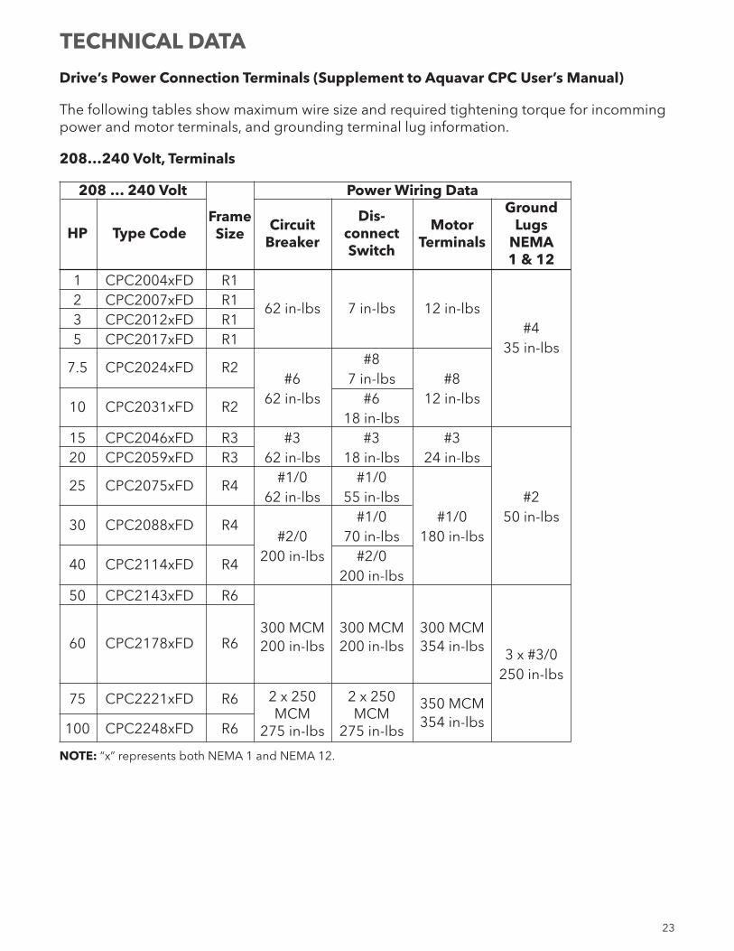
Drive’s Power Connection Terminals (Supplement to Aquavar CPC User’s Manual)
The following tables show maximum wire size and required tightening torque for incomming power and motor terminals, and grounding terminal lug information.
208…240 Volt, Terminals
208 … 240 Volt Power Wiring Data Dis- Ground HP Type Code Frame Circuit connect Motor Lugs Size Breaker Switch Terminals NEMA 1 & 12 1 CPC2004xFD R1 2 CPC2007xFD R1 62 in-lbs 7 in-lbs 12 in-lbs 3 CPC2012xFD R1 #4 5 CPC2017xFD R1 35 in-lbs 7.5 CPC2024xFD R2 #8 #6 7 in-lbs #8 10 CPC2031xFD R2 62 in-lbs #6 12 in-lbs 18 in-lbs 15 CPC2046xFD R3 #3 #3 #3 20 CPC2059xFD R3 62 in-lbs 18 in-lbs 24 in-lbs 25 CPC2075xFD R4 #1/0 #1/0 62 in-lbs 55 in-lbs #2 30 CPC2088xFD R4 #1/0 #1/0 50 in-lbs #2/0 70 in-lbs 180 in-lbs 40 CPC2114xFD R4 200 in-lbs #2/0 200 in-lbs 50 CPC2143xFD R6 60 CPC2178xFD R6 300 MCM 300 MCM 300 MCM
200 in-lbs 200 in-lbs 354 in-lbs 3 x #3/0 250 in-lbs 75 CPC2221xFD R6 2 x 250 2 x 250
350 MCM MCM MCM 354 in-lbs 100 CPC2248xFD R6 275 in-lbs 275 in-lbs
NOTE: “x” represents both NEMA 1 and NEMA 12.
TECHNICAL DATA
24
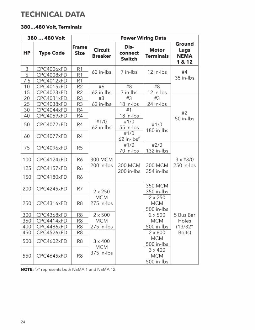
380…480 Volt, Terminals
380 … 480 Volt Power Wiring Data Dis- Ground HP Type Code Frame Circuit connect Motor Lugs Size Breaker Switch Terminals NEMA 1 & 12 3 CPC4006xFD R1 62 in-lbs 7 in-lbs 12 in-lbs #4 5 CPC4008xFD R1 35 in-lbs 7.5 CPC4012xFD R1 10 CPC4015xFD R2 #6 #8 #8 15 CPC4023xFD R2 62 in-lbs 7 in-lbs 12 in-lbs 20 CPC4031xFD R3 #3 #3 #3 25 CPC4038xFD R3 62 in-lbs 18 in-lbs 24 in-lbs 30 CPC4044xFD R4 #1 #2 40 CPC4059xFD R4 18 in-lbs 50 in-lbs 50 CPC4072xFD R4 #1/0 #1/0 #1/0 62 in-lbs 55 in-lbs 180 in-lbs 60 CPC4077xFD R4 #1/0 62 in-lbs2
75 CPC4096xFD R5 #1/0 #2/0 70 in-lbs 132 in-lbs 100 CPC4124xFD R6 300 MCM 3 x #3/0 200 in-lbs 300 MCM 300 MCM 250 in-lbs 125 CPC4157xFD R6 200 in-lbs 354 in-lbs 150 CPC4180xFD R6 200 CPC4245xFD R7 350 MCM 2 x 250 350 in-lbs MCM 2 x 250 250 CPC4316xFD R8 275 in-lbs MCM 500 in-lbs 300 CPC4368xFD R8 2 x 500 2 x 500 5 Bus Bar 350 CPC4414xFD R8 MCM MCM Holes 400 CPC4486xFD R8 275 in-lbs 500 in-lbs (13/32” 450 CPC4526xFD R8 2 x 600 Bolts) 500 CPC4602xFD R8 3 x 400 MCM MCM 500 in-lbs 375 in-lbs 3 x 400 550 CPC4645xFD R8 MCM 500 in-lbs
NOTE: “x” represents both NEMA 1 and NEMA 12.
TECHNICAL DATA
25
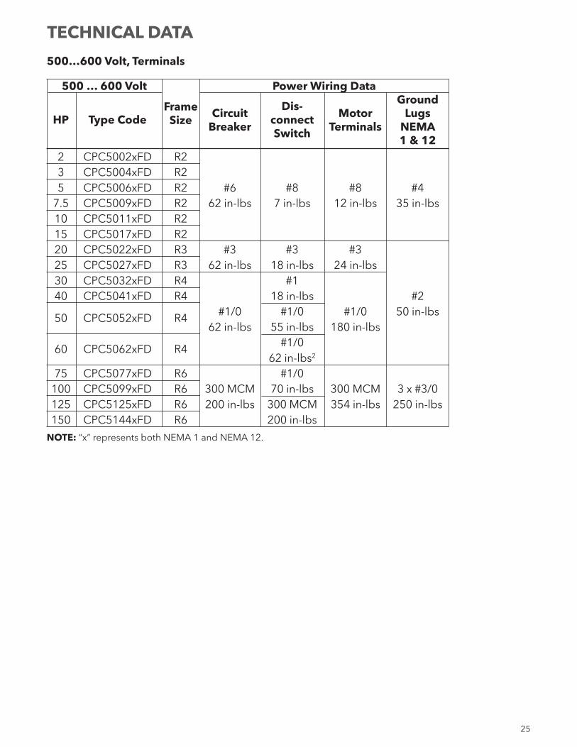
500…600 Volt, Terminals
500 … 600 Volt Power Wiring Data Dis- Ground HP Type Code Frame Circuit connect Motor Lugs Size Breaker Switch Terminals NEMA 1 & 12 2 CPC5002xFD R2 3 CPC5004xFD R2 5 CPC5006xFD R2 #6 #8 #8 #4 7.5 CPC5009xFD R2 62 in-lbs 7 in-lbs 12 in-lbs 35 in-lbs 10 CPC5011xFD R2 15 CPC5017xFD R2 20 CPC5022xFD R3 #3 #3 #3 25 CPC5027xFD R3 62 in-lbs 18 in-lbs 24 in-lbs 30 CPC5032xFD R4 #1 40 CPC5041xFD R4 18 in-lbs #2 50 CPC5052xFD R4 #1/0 #1/0 #1/0 50 in-lbs 62 in-lbs 55 in-lbs 180 in-lbs 60 CPC5062xFD R4 #1/0 62 in-lbs2
75 CPC5077xFD R6 #1/0 100 CPC5099xFD R6 300 MCM 70 in-lbs 300 MCM 3 x #3/0 125 CPC5125xFD R6 200 in-lbs 300 MCM 354 in-lbs 250 in-lbs 150 CPC5144xFD R6 200 in-lbs
NOTE: “x” represents both NEMA 1 and NEMA 12.
TECHNICAL DATA
26
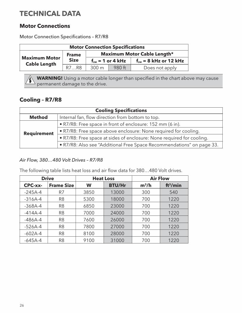
Motor Connections
Motor Connection Specifications – R7/R8
Motor Connection Specifications Maximum Motor
Frame Maximum Motor Cable Length*
Cable Length Size fsw = 1 or 4 kHz fsw = 8 kHz or 12 kHz
R7…R8 300 m 980 ft Does not apply
WARNING! Using a motor cable longer than specified in the chart above may cause permanent damage to the drive.
Cooling – R7/R8
Cooling Specifications Method Internal fan, flow direction from bottom to top. • R7/R8: Free space in front of enclosure: 152 mm (6 in). Requirement • R7/R8: Free space above enclosure: None required for cooling. • R7/R8: Free space at sides of enclosure: None required for cooling. • R7/R8: Also see “Additional Free Space Recommendations” on page 33.
Air Flow, 380…480 Volt Drives – R7/R8
The following table lists heat loss and air flow data for 380…480 Volt drives.
Drive Heat Loss Air Flow CPC-xx- Frame Size W BTU/Hr m3/h ft3/min -245A-4 R7 3850 13000 300 540 -316A-4 R8 5300 18000 700 1220 -368A-4 R8 6850 23000 700 1220 -414A-4 R8 7000 24000 700 1220 -486A-4 R8 7600 26000 700 1220 -526A-4 R8 7800 27000 700 1220 -602A-4 R8 8100 28000 700 1220 -645A-4 R8 9100 31000 700 1220
TECHNICAL DATA
27
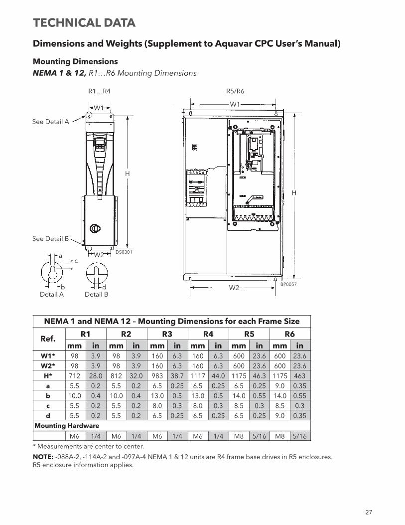
Dimensions and Weights (Supplement to Aquavar CPC User’s Manual)
Mounting DimensionsNEMA 1 & 12, R1…R6 Mounting Dimensions
NEMA 1 and NEMA 12 – Mounting Dimensions for each Frame Size
Ref. R1 R2 R3 R4 R5 R6 mm in mm in mm in mm in mm in mm in W1* 98 3.9 98 3.9 160 6.3 160 6.3 600 23.6 600 23.6
W2* 98 3.9 98 3.9 160 6.3 160 6.3 600 23.6 600 23.6
H* 712 28.0 812 32.0 983 38.7 1117 44.0 1175 46.3 1175 463
a 5.5 0.2 5.5 0.2 6.5 0.25 6.5 0.25 6.5 0.25 9.0 0.35
b 10.0 0.4 10.0 0.4 13.0 0.5 13.0 0.5 14.0 0.55 14.0 0.55
c 5.5 0.2 5.5 0.2 8.0 0.3 8.0 0.3 8.5 0.3 8.5 0.3
d 5.5 0.2 5.5 0.2 6.5 0.25 6.5 0.25 6.5 0.25 9.0 0.35
Mounting Hardware
M6 1/4 M6 1/4 M6 1/4 M6 1/4 M8 5/16 M8 5/16
* Measurements are center to center.
NOTE: -088A-2, -114A-2 and -097A-4 NEMA 1 & 12 units are R4 frame base drives in R5 enclosures. R5 enclosure information applies.
R1…R4
DS0301
BP0057
R5/R6
W1 W1
H
H
W2
W2
See Detail A
See Detail B
Detail BDetail A
ac
b d
TECHNICAL DATA
28
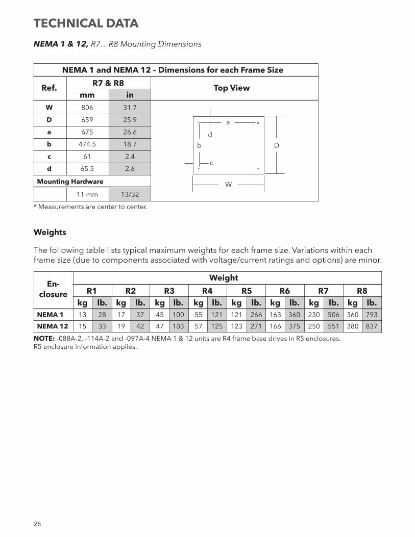
NEMA 1 & 12, R7…R8 Mounting Dimensions
NEMA 1 and NEMA 12 – Dimensions for each Frame Size
Ref. R7 & R8 Top View mm in W 806 31.7
D 659 25.9
a 675 26.6
b 474.5 18.7
c 61 2.4
d 65.5 2.6
Mounting Hardware
11 mm 13/32
* Measurements are center to center.
Weights
The following table lists typical maximum weights for each frame size. Variations within each frame size (due to components associated with voltage/current ratings and options) are minor.
En-
Weight
closure R1 R2 R3 R4 R5 R6 R7 R8 kg lb. kg lb. kg lb. kg lb. kg lb. kg lb. kg lb. kg lb. NEMA 1 13 28 17 37 45 100 55 121 121 266 163 360 230 506 360 793
NEMA 12 15 33 19 42 47 103 57 125 123 271 166 375 250 551 380 837
NOTE: -088A-2, -114A-2 and -097A-4 NEMA 1 & 12 units are R4 frame base drives in R5 enclosures. R5 enclosure information applies.
D
W
c
b
d
a
TECHNICAL DATA
29
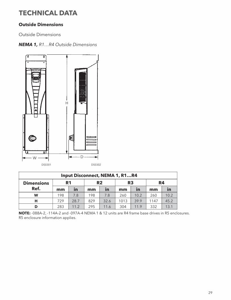
Outside Dimensions
Outside Dimensions
NEMA 1, R1…R4 Outside Dimensions
Input Disconnect, NEMA 1, R1…R4
Dimensions R1 R2 R3 R4 Ref. mm in mm in mm in mm in W 198 7.8 198 7.8 260 10.2 260 10.2
H 729 28.7 829 32.6 1013 39.9 1147 45.2
D 283 11.2 295 11.6 304 11.9 332 13.1
NOTE: -088A-2, -114A-2 and -097A-4 NEMA 1 & 12 units are R4 frame base drives in R5 enclosures. R5 enclosure information applies.
DS0301
W D
DS0302
H
TECHNICAL DATA
30
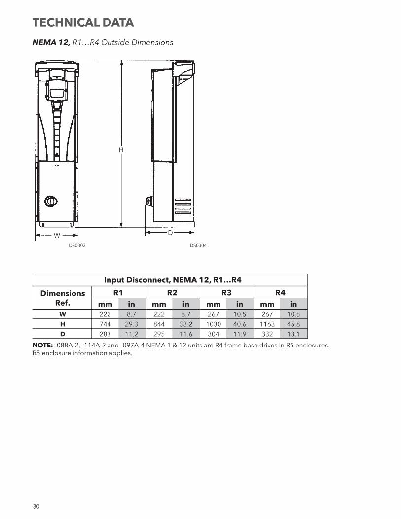
NEMA 12, R1…R4 Outside Dimensions
Input Disconnect, NEMA 12, R1…R4
Dimensions R1 R2 R3 R4 Ref. mm in mm in mm in mm in W 222 8.7 222 8.7 267 10.5 267 10.5
H 744 29.3 844 33.2 1030 40.6 1163 45.8
D 283 11.2 295 11.6 304 11.9 332 13.1
NOTE: -088A-2, -114A-2 and -097A-4 NEMA 1 & 12 units are R4 frame base drives in R5 enclosures. R5 enclosure information applies.
DS0303
W D
DS0304
H
TECHNICAL DATA
31
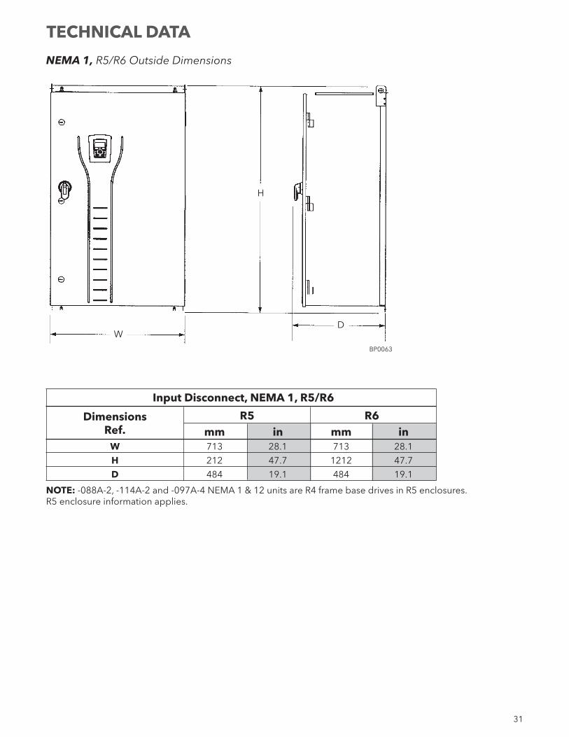
NEMA 1, R5/R6 Outside Dimensions
Input Disconnect, NEMA 1, R5/R6
Dimensions R5 R6 Ref. mm in mm in W 713 28.1 713 28.1
H 212 47.7 1212 47.7
D 484 19.1 484 19.1
NOTE: -088A-2, -114A-2 and -097A-4 NEMA 1 & 12 units are R4 frame base drives in R5 enclosures. R5 enclosure information applies.
WD
BP0063
H
TECHNICAL DATA
32
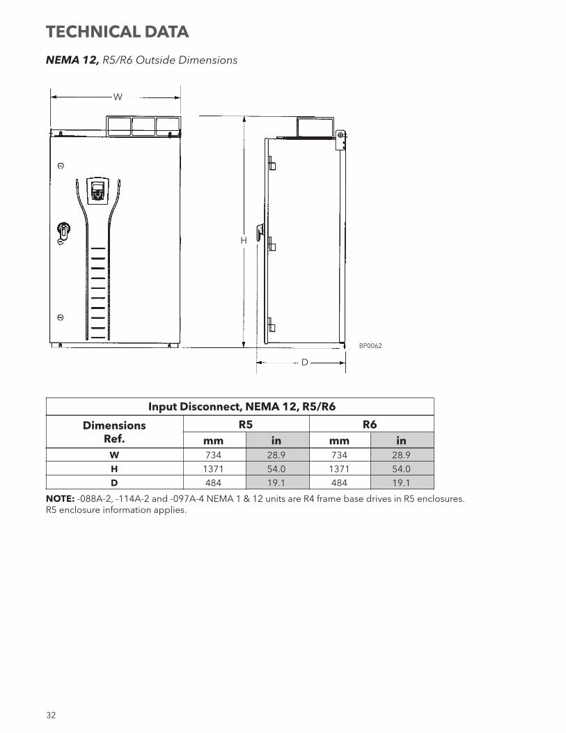
NEMA 12, R5/R6 Outside Dimensions
Input Disconnect, NEMA 12, R5/R6
Dimensions R5 R6 Ref. mm in mm in W 734 28.9 734 28.9
H 1371 54.0 1371 54.0
D 484 19.1 484 19.1
NOTE: -088A-2, -114A-2 and -097A-4 NEMA 1 & 12 units are R4 frame base drives in R5 enclosures. R5 enclosure information applies.
W
D
BP0062
H
TECHNICAL DATA
33
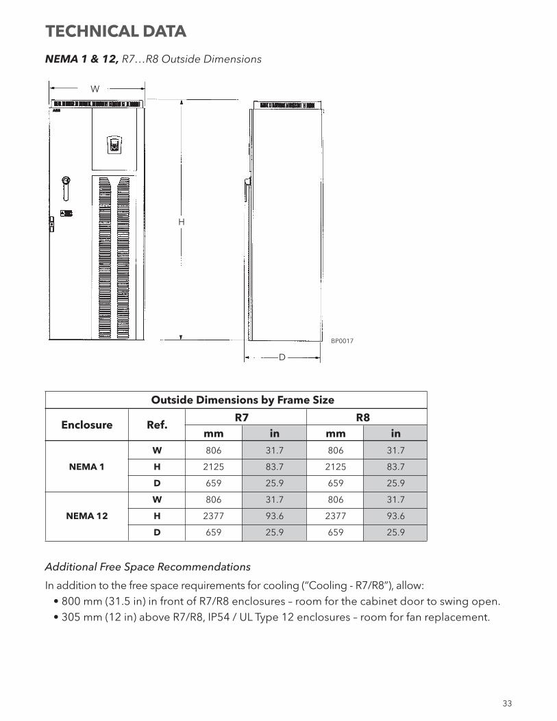
NEMA 1 & 12, R7…R8 Outside Dimensions
Outside Dimensions by Frame Size
Enclosure Ref.
R7 R8 mm in mm in W 806 31.7 806 31.7
NEMA 1 H 2125 83.7 2125 83.7
D 659 25.9 659 25.9
W 806 31.7 806 31.7
NEMA 12 H 2377 93.6 2377 93.6
D 659 25.9 659 25.9
Additional Free Space Recommendations
In addition to the free space requirements for cooling (“Cooling - R7/R8”), allow:• 800 mm (31.5 in) in front of R7/R8 enclosures – room for the cabinet door to swing open.• 305 mm (12 in) above R7/R8, IP54 / UL Type 12 enclosures – room for fan replacement.
D
BP0017
H
W
TECHNICAL DATA
34
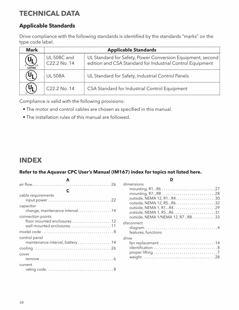
Applicable Standards
Drive compliance with the following standards is identified by the standards “marks” on the type code label.
Mark Applicable Standards
UL 508C and UL Standard for Safety, Power Conversion Equipment, second C22.2 No. 14 edition and CSA Standard for Industrial Control Equipment
UL 508A UL Standard for Safety, Industrial Control Panels
C22.2 No. 14 CSA Standard for Industrial Control Equipment
Compliance is valid with the following provisions:
• The motor and control cables are chosen as specified in this manual.
• The installation rules of this manual are followed.
C US
UL®
UL®
C
UL®
LISTED
Refer to the Aquavar CPC User’s Manual (IM167) index for topics not listed here.
Aair flow. . . . . . . . . . . . . . . . . . . . . . . . . . . . . . . . . . . . . . . .26
Ccable requirements input power . . . . . . . . . . . . . . . . . . . . . . . . . . . . . . . .22
capacitor change, maintenance interval. . . . . . . . . . . . . . . . .14
connection points floor mounted enclosures . . . . . . . . . . . . . . . . . . . .12 wall mounted enclosures. . . . . . . . . . . . . . . . . . . . .11
model code . . . . . . . . . . . . . . . . . . . . . . . . . . . . . . . . . . . . 8
control panel maintenance interval, battery . . . . . . . . . . . . . . . . .14
cooling . . . . . . . . . . . . . . . . . . . . . . . . . . . . . . . . . . . . . . .26
cover remove . . . . . . . . . . . . . . . . . . . . . . . . . . . . . . . . . . . . . 6
current rating code. . . . . . . . . . . . . . . . . . . . . . . . . . . . . . . . . . 8
Ddimensions mounting, R1...R6 . . . . . . . . . . . . . . . . . . . . . . . . . . .27 mounting, R7...R8 . . . . . . . . . . . . . . . . . . . . . . . . . . .28 outside, NEMA 12, R1...R4. . . . . . . . . . . . . . . . . . . .30 outside, NEMA 12, R5...R6. . . . . . . . . . . . . . . . . . . .32 outside, NEMA 1, R1...R4 . . . . . . . . . . . . . . . . . . . . .29 outside, NEMA 1, R5...R6 . . . . . . . . . . . . . . . . . . . . .31 outside, NEMA 1/NEMA 12, R7...R8. . . . . . . . . . . .33
disconnect diagram . . . . . . . . . . . . . . . . . . . . . . . . . . . . . . . . . . . . 4 features, functions
drive fan replacement . . . . . . . . . . . . . . . . . . . . . . . . . . . .14 identification . . . . . . . . . . . . . . . . . . . . . . . . . . . . . . . . 8 proper lifting . . . . . . . . . . . . . . . . . . . . . . . . . . . . . . . . 7 weight . . . . . . . . . . . . . . . . . . . . . . . . . . . . . . . . . . . . .28
TECHNICAL DATA
INDEX
35
Eenclosure protection class code. . . . . . . . . . . . . . . . . . . 8
enclosure, NEMA 12 air filter maintenance . . . . . . . . . . . . . . . . . . . . . . . .16 fan replacement . . . . . . . . . . . . . . . . . . . . . . . . . . . .15
Ffan, drive module maintenance interval . . . . . . . . . . . . . . . . . . . . . . . .14 replacement procedure. . . . . . . . . . . . . . . . . . . . . .14
fan, enclosure maintenance interval . . . . . . . . . . . . . . . . . . . . . . . .14 replacement procedure. . . . . . . . . . . . . . . . . . . . . .14
filter, enclosure R5/R6 inlet, maintenance interval. . . . . . . . . . . . . .14 R5/R6 inlet, maintenance procedure . . . . . . . . . . .16 R7/R8, exhaust, maintenance interval . . . . . . . . . .14 R7/R8, exhaust, maintenance procedure . . . . . . .18 R7/R8, inlet, maintenance interval . . . . . . . . . . . . .14 R7/R8, inlet, maintenance procedure . . . . . . . . . .16
free space for access, R7/R8. . . . . . . . . . . . . . . . . . . . . . . . . . . .33
for cooling . . . . . . . . . . . . . . . . . . . . . . . . . . . . . . . . . . . .26
fuses . . . . . . . . . . . . . . . . . . . . . . . . . . . . . . . . . . . . . . . . .20 208...240 volt drives . . . . . . . . . . . . . . . . . . . . . . . . .20 380...480 volt drives . . . . . . . . . . . . . . . . . . . . . . . . .21 500...600 volt drives . . . . . . . . . . . . . . . . . . . . . . . . .22
Ggrounding requirements . . . . . . . . . . . . . . . . . . . . . . . . . . . . . . .10
Hheat loss . . . . . . . . . . . . . . . . . . . . . . . . . . . . . . . . . . . . . .26
heatsink maintenance interval . . . . . . . . . . . . . . . . . . . . . . . .14
Iinput disconnect see disconnect
input power cable/wire requirements . . . . . . . . . . . . . . . . . . . . .22 fuses . . . . . . . . . . . . . . . . . . . . . . . . . . . . . . . . . . . . . .20
installation flow chart . . . . . . . . . . . . . . . . . . . . . . . . . . . . . . . . . . . 6 preparation . . . . . . . . . . . . . . . . . . . . . . . . . . . . . . . . . 7
Llabel type code . . . . . . . . . . . . . . . . . . . . . . . . . . . . . . . . . . . 8
location, mounting . . . . . . . . . . . . . . . . . . . . . . . . . . . . . . 9
Mmaintenance drive module fan replacement . . . . . . . . . . . . . . . .14 enclosure fan replacement . . . . . . . . . . . . . . . . . . .14 intervals . . . . . . . . . . . . . . . . . . . . . . . . . . . . . . . . . . .14 R5/R6 enclosure inlet filter . . . . . . . . . . . . . . . . . . .16 R7/R8 enclosure exhaust filter . . . . . . . . . . . . . . . .18 R7/R8 enclosure inlet filter . . . . . . . . . . . . . . . . . . .16
manuals, listing . . . . . . . . . . . . . . . . . . . . . . . . . . . . . . . . . ii
motor connection specifications . . . . . . . . . . . . . . . . . . . .26
motor cable maximum length . . . . . . . . . . . . . . . . . . . . . . . . . . . .26
NNEMA 1 code . . . . . . . . . . . . . . . . . . . . . . . . . . . . . . . . . . . . . . . 8
NEMA 12 code . . . . . . . . . . . . . . . . . . . . . . . . . . . . . . . . . . . . . . . 8
Rratings . . . . . . . . . . . . . . . . . . . . . . . . . . . . . . . . . . . . . . . .19
remove cover . . . . . . . . . . . . . . . . . . . . . . . . . . . . . . . . . . . 6
Ssafety . . . . . . . . . . . . . . . . . . . . . . . . . . . . . . . . . . . . . . . . . . 3
specifications cooling . . . . . . . . . . . . . . . . . . . . . . . . . . . . . . . . . . . .26 motor connections . . . . . . . . . . . . . . . . . . . . . . . . . .26
standards . . . . . . . . . . . . . . . . . . . . . . . . . . . . . . . . . . . . .34 C22.2 No. 14 . . . . . . . . . . . . . . . . . . . . . . . . . . . . . . .34 UL 508C . . . . . . . . . . . . . . . . . . . . . . . . . . . . . . . . . . .34
Tterminals power, wire sizes . . . . . . . . . . . . . . . . . . . . . . . . . . . .23
type code . . . . . . . . . . . . . . . . . . . . . . . . . . . . . . . . . . . . . . 8
Vvoltage rating code. . . . . . . . . . . . . . . . . . . . . . . . . . . . . . . . . . 8
Wwarning automatic start up . . . . . . . . . . . . . . . . . . . . . . . . . . . . 3 dangerous voltages . . . . . . . . . . . . . . . . . . . . . . . . . . 3 listing. . . . . . . . . . . . . . . . . . . . . . . . . . . . . . . . . . . . . . . 3 parallel control connections . . . . . . . . . . . . . . . . . . . 3 qualified installer. . . . . . . . . . . . . . . . . . . . . . . . . . . . . 3
weight drive . . . . . . . . . . . . . . . . . . . . . . . . . . . . . . . . . . . . . .28
wiring connection diagrams, floor mounted . . . . . . . . . .12 connection diagrams, wall mounted . . . . . . . . . . .11 line input installation . . . . . . . . . . . . . . . . . . . . . . . .13 overview . . . . . . . . . . . . . . . . . . . . . . . . . . . . . . . . . . .11 requirements . . . . . . . . . . . . . . . . . . . . . . . . . . . . . . .10
INDEX
CENTRIPRO LIMITED WARRANTY
This warranty applies to all Aquavar CPC controllers manufactured by Xylem, Inc.
Any part or parts found to be defective within the warranty period shall be replaced at no charge to the dealer during the warranty period. The warranty period shall exist for a period of twenty-four (24) months from date of installation or thirty (30) months from date of manufacture, whichever period is shorter.
A dealer who believes that a warranty claim exists must contact the authorized CentriPro distributor from whom the controller was purchased and furnish complete details regarding the claim. The distributor is authorized to adjust any warranty claims utilizing the CentriPro Customer Service Department.
The warranty excludes:
(a) Labor, transportation and related costs incurred by the dealer;
(b) Reinstallation costs of repaired equipment;
(c) Reinstallation costs of replacement equipment;
(d) Consequential damages of any kind; and,
(e) Reimbursement for loss caused by interruption of service.
For purposes of this warranty, the following terms have these definitions:
(1) “Distributor” means any individual, partnership, corporation, association, or other legal relationship that stands between CentriPro and the dealer in purchases, consignments or contracts for sale of the subject controllers.
(2) “Dealer” means any individual, partnership, corporation, association, or other legal relationship which engages in the business of selling or leasing controllers to customers.
(3) “Customer” means any entity who buys or leases the subject controllers from a dealer. The “customer” may mean an individual, partnership, corporation, limited liability company, association or other legal entity which may engage in any type of business.
THIS WARRANTY EXTENDS TO THE DEALER ONLY.
CentriPro and Aquavar are trademarks of Xylem Inc. or one of its subsidiaries. DUSTLOK® is a registered trademark of Fiberbond Corp.© 2012 Xylem Inc. IM250 Revision Number 2 February 2013
Xylem, Inc.2881 East Bayard Street Ext., Suite ASeneca Falls, NY 13148Phone: (800) 453-6777 Fax: (888) 322-5877www.centripro.com