Embed Size (px)
Citation preview
D9124 Control PanelArchitectural & Engineering Specifications
1.0 General............................................................................................... 31.1 Scope of Work..................................................................................................... 31.1.1 Introduction ....................................................................................................................................................... 31.1.2 Work Included Under this Section .................................................................................................................... 31.1.3 Related Work Specified Under Other Sections of These Specifications (Related Sections)............................ 3
1.2 General Conditions............................................................................................. 31.2.1 Submittals at Bid Time...................................................................................................................................... 31.2.2 Submittals After Award of Contract................................................................................................................... 31.2.3 Documentation to be Submitted by the Contractor upon Completion of System Installation ........................... 41.2.4 Training ............................................................................................................................................................. 41.2.5 System Approvals ............................................................................................................................................. 41.2.6 Quality Assurance............................................................................................................................................. 41.2.7 Warranty ........................................................................................................................................................... 41.2.8 Service/Maintenance ........................................................................................................................................ 4
2.0 Products ............................................................................................ 52.1 System Description ............................................................................................ 52.2 System Feature/Capability Summary................................................................ 52.2.1 Number of Loops/Sensors ................................................................................................................................ 52.2.2 Programming Point Functionality...................................................................................................................... 62.2.3 Areas/Accounts................................................................................................................................................. 62.2.4 Number of Alarm Command Centers ............................................................................................................... 62.2.5 Number of User Passcodes.............................................................................................................................. 62.2.6 Communication Formats................................................................................................................................... 62.2.7 Testing, Diagnostic and Programmable Facilities............................................................................................. 62.2.8 Logger Capacities and Formats........................................................................................................................ 62.2.9 Reports ............................................................................................................................................................. 72.2.10 Telephone Lines, IP Addresses, and “Phone Routing”..................................................................................... 72.2.11 Number and Programmability of Relay Output Modules .................................................................................. 72.2.12 Number and Alarm Output Selections .............................................................................................................. 72.2.13 Miscellaneous Features.................................................................................................................................... 72.2.14 Real-Time Clock, Calendar and Test Timer ..................................................................................................... 82.2.15 Opening and Closing Windows......................................................................................................................... 82.2.16 DACS 24 Volt Power Rating ............................................................................................................................. 82.2.17 DACS Power Ratings ....................................................................................................................................... 82.2.18 DACS Fault Detection....................................................................................................................................... 82.2.19 User-Programmable Features .......................................................................................................................... 82.2.20 User-Programmable/Activated Functions ......................................................................................................... 8
2.3 System Interface Requirements ........................................................................ 92.3.1 Grounding ......................................................................................................................................................... 92.3.2 Primary Power .................................................................................................................................................. 92.3.3 Primary Power Supervision .............................................................................................................................. 92.3.4 Secondary Power (Standby Battery) ................................................................................................................ 92.3.5 Secondary Power Supervision.......................................................................................................................... 92.3.6 Wiring................................................................................................................................................................ 92.3.7 EMI/Lightning Protection................................................................................................................................... 92.3.8 Telephone Interface.......................................................................................................................................... 92.3.9 Ethernet Interface ........................................................................................................................................... 10
D9124General
D9124 A&E Specifications74-07193-000-D Page 2 © 2003 Bosch Security Systems
2.3.10 Auxiliary Function Control Interface ................................................................................................................10
2.4 Materials............................................................................................................. 102.4.1 DACS (Digital Alarm Communicator and Access Control System).................................................................102.4.2 System Accessories........................................................................................................................................102.4.3 Power Supply ..................................................................................................................................................112.4.4 Communication Accessories...........................................................................................................................112.4.5 Fire System Initiating Devices and Accessories .............................................................................................122.4.6 Indicating Devices and Accessories ...............................................................................................................132.4.7 Annunciation Devices......................................................................................................................................142.4.8 Voice Evacuation System and Accessories....................................................................................................14
3.0 Execution .........................................................................................153.1 Installation ......................................................................................................... 153.2 Supervision........................................................................................................ 153.3 Programming..................................................................................................... 153.4 Testing ............................................................................................................... 153.4.1 Operational Testing.........................................................................................................................................153.4.2 Hard-Copy System Printout ............................................................................................................................153.4.3 Acceptance Test Plan Form............................................................................................................................15
3.5 Commissioning ................................................................................................. 15
D9124General
D9124 A&E Specifications© 2003 Bosch Security Systems Page 3 74-07193-000-D
1.0 General1.1 Scope of Work1.1.1 Introduction
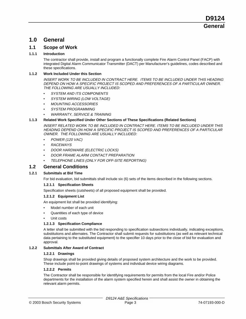
The contractor shall provide, install and program a functionally complete Fire Alarm Control Panel (FACP) withintegrated Digital Alarm Communicator Transmitter (DACT) per Manufacturer’s guidelines, codes described andthese specifications.
1.1.2 Work Included Under this Section
INSERT WORK TO BE INCLUDED IN CONTRACT HERE. ITEMS TO BE INCLUDED UNDER THIS HEADINGDEPEND ON HOW A SPECIFIC PROJECT IS SCOPED AND PREFERENCES OF A PARTICULAR OWNER.THE FOLLOWING ARE USUALLY INCLUDED:
• SYSTEM AND ITS COMPONENTS• SYSTEM WIRING (LOW VOLTAGE)• MOUNTING ACCESSORIES• SYSTEM PROGRAMMING• WARRANTY, SERVICE & TRAINING
1.1.3 Related Work Specified Under Other Sections of These Specifications (Related Sections)
INSERT RELATED WORK TO BE INCLUDED IN CONTRACT HERE. ITEMS TO BE INCLUDED UNDER THISHEADING DEPEND ON HOW A SPECIFIC PROJECT IS SCOPED AND PREFERENCES OF A PARTICULAROWNER. THE FOLLOWING ARE USUALLY INCLUDED:
• POWER (120 VAC)• RACEWAYS• DOOR HARDWARE (ELECTRIC LOCKS)• DOOR FRAME ALARM CONTACT PREPARATION• TELEPHONE LINES (ONLY FOR OFF-SITE REPORTING)
1.2 General Conditions1.2.1 Submittals at Bid Time
For bid evaluation, bid submittals shall include six (6) sets of the items described in the following sections.
1.2.1.1 Specification Sheets
Specification sheets (cutsheets) of all proposed equipment shall be provided.
1.2.1.2 Equipment List
An equipment list shall be provided identifying:
• Model number of each unit
• Quantities of each type of device
• Unit costs
1.2.1.3 Specification Compliance
A letter shall be submitted with the bid responding to specification subsections individually, indicating exceptions,substitutions and alternates. The Contractor shall submit requests for substitutions (as well as relevant technicaldata pertaining to the substituted equipment) to the specifier 10 days prior to the close of bid for evaluation andapproval.
1.2.2 Submittals After Award of Contract
1.2.2.1 Drawings
Shop drawings shall be provided giving details of proposed system architecture and the work to be provided.These include point-to-point drawings of systems and individual device wiring diagrams.
1.2.2.2 Permits
The Contractor shall be responsible for identifying requirements for permits from the local Fire and/or Policedepartments for the installation of the alarm system specified herein and shall assist the owner in obtaining therelevant alarm permits.
D9124General
D9124 A&E Specifications74-07193-000-D Page 4 © 2003 Bosch Security Systems
1.2.3 Documentation to be Submitted by the Contractor upon Completion of System Installation
1.2.3.1 As-Built Drawings
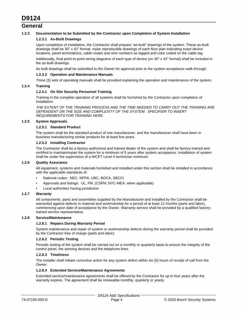
Upon completion of installation, the Contractor shall prepare “as-built” drawings of the system. These as-builtdrawings shall be 30" x 42" format, mylar reproducible drawings of each floor plan indicating exact devicelocations, panel terminations, cable routes and wire numbers as tagged and color coded on the cable tag.
Additionally, final point-to-point wiring diagrams of each type of device (on 30" x 42" format) shall be included inthe as-built drawings.
As built drawings shall be submitted to the Owner for approval prior to the system acceptance walk-through.
1.2.3.2 Operation and Maintenance Manuals
Three (3) sets of operating manuals shall be provided explaining the operation and maintenance of the system.
1.2.4 Training
1.2.4.1 On Site Security Personnel Training
Training in the complete operation of all systems shall be furnished by the Contractor upon completion ofinstallation.
THE EXTENT OF THE TRAINING PROCESS AND THE TIME NEEDED TO CARRY OUT THE TRAINING AREDEPENDENT ON THE SIZE AND COMPLEXITY OF THE SYSTEM. SPECIFIER TO INSERTREQUIREMENTS FOR TRAINING HERE.
1.2.5 System Approvals
1.2.5.1 Standard Product
The system shall be the standard product of one manufacturer, and the manufacturer shall have been inbusiness manufacturing similar products for at least five years.
1.2.5.2 Installing Contractor
The Contractor shall be a factory-authorized and trained dealer of the system and shall be factory-trained andcertified to maintain/repair the system for a minimum of 5 years after system acceptance. Installation of systemshall be under the supervision of a NICET Level II technician minimum.
1.2.6 Quality Assurance
All equipment, systems and materials furnished and installed under this section shall be installed in accordancewith the applicable standards of:
• National codes: NEC, NFPA, UBC, BOCA, SBCCI
• Approvals and listings: UL, FM, (CSFM, NYC-MEA, when applicable)
• Local authorities having jurisdiction
1.2.7 Warranty
All components, parts and assemblies supplied by the Manufacturer and installed by the Contractor shall bewarranted against defects in material and workmanship for a period of at least 12 months (parts and labor),commencing upon date of acceptance by the Owner. Warranty service shall be provided by a qualified factory-trained service representative.
1.2.8 Service/Maintenance
1.2.8.1 Repairs During Warranty Period
System maintenance and repair of system or workmanship defects during the warranty period shall be providedby the Contractor free of charge (parts and labor).
1.2.8.2 Periodic Testing
Periodic testing of the system shall be carried out on a monthly or quarterly basis to ensure the integrity of thecontrol panel, the sensing devices and the telephone lines.
1.2.8.3 Timeliness
The installer shall initiate corrective action for any system defect within six (6) hours of receipt of call from theOwner.
1.2.8.4 Extended Service/Maintenance Agreements
Extended service/maintenance agreements shall be offered by the Contractor for up to four years after thewarranty expires. The agreement shall be renewable monthly, quarterly or yearly.
D9124Products
D9124 A&E Specifications© 2003 Bosch Security Systems Page 5 74-07193-000-D
2.0 Products2.1 System Description
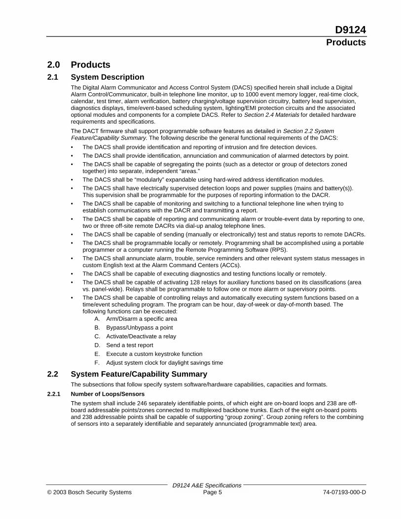
The Digital Alarm Communicator and Access Control System (DACS) specified herein shall include a DigitalAlarm Control/Communicator, built-in telephone line monitor, up to 1000 event memory logger, real-time clock,calendar, test timer, alarm verification, battery charging/voltage supervision circuitry, battery lead supervision,diagnostics displays, time/event-based scheduling system, lighting/EMI protection circuits and the associatedoptional modules and components for a complete DACS. Refer to Section 2.4 Materials for detailed hardwarerequirements and specifications.
The DACT firmware shall support programmable software features as detailed in Section 2.2 SystemFeature/Capability Summary. The following describe the general functional requirements of the DACS:
• The DACS shall provide identification and reporting of intrusion and fire detection devices.
• The DACS shall provide identification, annunciation and communication of alarmed detectors by point.
• The DACS shall be capable of segregating the points (such as a detector or group of detectors zonedtogether) into separate, independent “areas.”
• The DACS shall be “modularly” expandable using hard-wired address identification modules.
• The DACS shall have electrically supervised detection loops and power supplies (mains and battery(s)).This supervision shall be programmable for the purposes of reporting information to the DACR.
• The DACS shall be capable of monitoring and switching to a functional telephone line when trying toestablish communications with the DACR and transmitting a report.
• The DACS shall be capable of reporting and communicating alarm or trouble-event data by reporting to one,two or three off-site remote DACRs via dial-up analog telephone lines.
• The DACS shall be capable of sending (manually or electronically) test and status reports to remote DACRs.
• The DACS shall be programmable locally or remotely. Programming shall be accomplished using a portableprogrammer or a computer running the Remote Programming Software (RPS).
• The DACS shall annunciate alarm, trouble, service reminders and other relevant system status messages incustom English text at the Alarm Command Centers (ACCs).
• The DACS shall be capable of executing diagnostics and testing functions locally or remotely.
• The DACS shall be capable of activating 128 relays for auxiliary functions based on its classifications (areavs. panel-wide). Relays shall be programmable to follow one or more alarm or supervisory points.
• The DACS shall be capable of controlling relays and automatically executing system functions based on atime/event scheduling program. The program can be hour, day-of-week or day-of-month based. Thefollowing functions can be executed:
A. Arm/Disarm a specific area
B. Bypass/Unbypass a point
C. Activate/Deactivate a relay
D. Send a test report
E. Execute a custom keystroke function
F. Adjust system clock for daylight savings time
2.2 System Feature/Capability SummaryThe subsections that follow specify system software/hardware capabilities, capacities and formats.
2.2.1 Number of Loops/Sensors
The system shall include 246 separately identifiable points, of which eight are on-board loops and 238 are off-board addressable points/zones connected to multiplexed backbone trunks. Each of the eight on-board pointsand 238 addressable points shall be capable of supporting “group zoning”. Group zoning refers to the combiningof sensors into a separately identifiable and separately annunciated (programmable text) area.

D9124Products
D9124 A&E Specifications74-07193-000-D Page 6 © 2003 Bosch Security Systems
2.2.2 Programming Point Functionality
For each point in the system, the following characteristics shall be programmable:
• Always on (24 hour response)
• On when the system is Master Armed
• Only on when the system is Perimeter Armed
• Displays/does not display at the ACC when the point is activated
• Provides/does not provide entry warning tone
• Sounds/does not sound audible alarm indication
• The point is bypassable/not bypassable
• Alarm verification with programmable verification time
• Summary relay activation by point
• Provides/does not provide “Supervisory point” capability
• Provides/does not provide “watch point” capability
• Arms or disarms the area to which the point is assigned when the input changes states
2.2.3 Areas/Accounts
The DACS shall support eight (8) independent areas. Each of the eight areas shall have custom text associatedwith the armed state, the disarmed state and the point-of-normal state. Additionally, the DACS shall be capableof assigning a unique account identifier to each of the areas, depending on the distribution of areas per account.
The DACS shall be capable of logically grouping one or more points into an area, or conversely, dividing the 246points into one or more areas.
Any area shall be configurable to allow arming by specific users when a programmable number of devices arefaulted or bypassed.
Areas shall be independently controlled by their corresponding ACCs. Each ACC can be designated to control aspecific area, or group of areas, or all areas in the system.
Independent control or relay functions by area shall be possible through programming assignments.
2.2.4 Number of Alarm Command Centers
The system shall accommodate 32 ACCs, each capable of displaying custom English text on vacuum florescentdisplays and sounding different patterns of audible alarm for different events. Up to eight (8) ACCs shall becapable of being supervised at one time.
2.2.5 Number of User Passcodes
Up to 249 different passcodes shall be possible. Each passcode shall be three (3) to six (6) digits (variable).Passcodes shall be enabled or disabled by area(s) and shall be assigned one of 14 different authority levels tocarry out functions such as the activation of relays from the ACC. These passcodes shall also be required forcarrying various system functions such as arming the system, disarming the system, transmitting a duress code,resetting the system and silencing sounders.
2.2.6 Communication Formats
The Radionics Modem IIIa² format shall be utilized for optimum system performance. The DACT shall report to aCommercial Central Station using a Bosch Security Systems D6600 Alarm Receiver that supports the RadionicsModem IIIa² communication format. The D6600 shall provide point identification information transmission toDACRs (Alarms, Troubles and Restorals by point). It shall also provide the actual point number, point text, actualuser number, bypassed points, relay activation, opening/closing reports by up to 249 users, late, early, or failopening/closing reports and opening/closing reports by area.
2.2.7 Testing, Diagnostic and Programmable Facilities
Automatic test reports and remote system access for diagnostics, programming and log (Logger) uploads shallalso be supported via a remote central station computer utilizing RPS.
2.2.8 Logger Capacities and Formats
The system shall be capable of logging up to 1000 events indicating time, date, type of event, account number,area number, user ID, point text and primary/secondary telephone number called for each event. Logs shall beviewed locally at the ACC and remotely via an upload to a computer running RPS software. The DACS shall alsosupport the printing of these events on up to three local parallel printers. The DACS shall also send a report tothe DACR when the log reaches a programmable “percent full capacity” so that RPS can retrieve the storedevents. Events shall be routed to specific printers by group, signal type and area.
D9124Products
D9124 A&E Specifications© 2003 Bosch Security Systems Page 7 74-07193-000-D
2.2.9 Reports
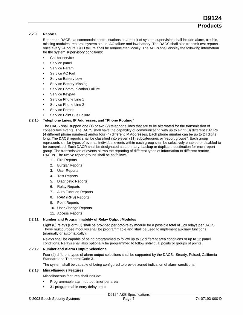
Reports to DACRs at commercial central stations as a result of system supervision shall include alarm, trouble,missing modules, restoral, system status, AC failure and low battery. The DACS shall also transmit test reportsonce every 24 hours. CPU failure shall be annunciated locally. The ACCs shall display the following informationfor the system supervisory conditions:
• Call for service
• Service panel
• Service Param
• Service AC Fail
• Service Battery Low
• Service Battery Missing
• Service Communication Failure
• Service Keypad
• Service Phone Line 1
• Service Phone Line 2
• Service Printer
• Service Point Bus Failure
2.2.10 Telephone Lines, IP Addresses, and “Phone Routing”
The DACS shall support one (1) or two (2) telephone lines that are to be alternated for the transmission ofconsecutive events. The DACS shall have the capability of communicating with up to eight (8) different DACRs(4 different phone numbers) and/or four (4) different IP Addresses. Each phone number can be up to 24 digitslong. The DACS reports shall be classified into eleven (11) subcategories or “report groups”. Each grouprepresents similar types of events. Individual events within each group shall be selectively enabled or disabled tobe transmitted. Each DACR shall be designated as a primary, backup or duplicate destination for each reportgroup. The transmission of events allows the reporting of different types of information to different remoteDACRs. The twelve report groups shall be as follows:
1. Fire Reports
2. Burglar Reports
3. User Reports
4. Test Reports
5. Diagnostic Reports
6. Relay Reports
7. Auto Function Reports
8. RAM (RPS) Reports
9. Point Reports
10. User Change Reports
11. Access Reports
2.2.11 Number and Programmability of Relay Output Modules
Eight (8) relays (Form C) shall be provided per octo-relay module for a possible total of 128 relays per DACS.These multipurpose modules shall be programmable and shall be used to implement auxiliary functions(manually or automatically).
Relays shall be capable of being programmed to follow up to 12 different area conditions or up to 12 panelconditions. Relays shall also optionally be programmed to follow individual points or groups of points.
2.2.12 Number and Alarm Output Selections
Four (4) different types of alarm output selections shall be supported by the DACS: Steady, Pulsed, CaliforniaStandard and Temporal Code 3.
The system shall be capable of being configured to provide zoned indication of alarm conditions.
2.2.13 Miscellaneous Features
Miscellaneous features shall include:
• Programmable alarm output timer per area
• 31 programmable entry delay times
D9124Products
D9124 A&E Specifications74-07193-000-D Page 8 © 2003 Bosch Security Systems
• Exit delay programmable by area
• Individually programmable point-of-protection text
• Point bypassing
• Keyswitch arming capability with LED outputs
2.2.14 Real-Time Clock, Calendar and Test Timer
The FDAC system shall incorporate an integral real-time clock, calendar and a test timer.
2.2.15 Opening and Closing Windows
The system shall be programmed with “normal” opening and closing periods for each day of the week and thussuppress scheduled opening/closing reports and report only the exceptions, that is, openings and closingsoutside the predefined time window. The DACS shall have the capability of suppressing opening and closingreports, overriding the programmed open and close windows during holidays and automatically arming the DACS(by area) at the end of the closing period.
2.2.16 DACS 24 Volt Power Rating
The DACS shall provide 4 amps of auxiliary power for use with initiating and indicating devices. Additionalauxiliary power shall be provided by adding D9142 power supplies.
2.2.17 DACS Power Ratings
The DACS shall provide 1.4 amps of auxiliary power and 2 amps of alarm power, both rated at 12 VDC.Additional auxiliary power shall be provided by adding battery/charger modules up to a maximum of 2 amps.
2.2.18 DACS Fault Detection
The DACS shall check the point sensor loops once every 300 milliseconds. The point response time isprogrammable over a range of 300 milliseconds to 4.5 seconds.
2.2.19 User-Programmable Features
The DACS shall provide a “user-friendly” interface for programming/customizing the system to the operationalcriteria of the application. The DACS shall be capable of being operated through either:
• The Command Structure
• Menu/Command List
These system features shall have restrictions based on 14 individually programmable levels of passcodeauthority that can be assigned to system users. The user’s passcode shall have the capability of being assigneda different authority level in each of the eight (8) areas. There shall be the capability to assign a Servicepasscode to the servicing agent allowing that agent limited access to system functions.
2.2.20 User-Programmable/Activated Functions
User-programmable/activated functions shall include:
• Arming the system: All areas, specific area(s) only, perimeter instant, perimeter delayed, perimeter partial,watch mode and arming the system with a duress passcode.
• Disarming the system: All areas, specific area(s) only and disarming with a duress passcode.
• Viewing system status: Faulted points, event memory, bypassed points, area status and point status.
• Implementation functions: Bypass a point, unbypass a point, reset sensors, silence bell, activate relays,initiate the remote programming function locally to allow programming the system from a remote location.The ACCs can also be temporarily readdressed to view the status of a remote area.
• Testing the system: Local Walk test, Service Walk test, Fire test, send report to remote DACR to check thetelephone and/or Ethernet link and programming the time and date for the next test report transmission.
• Change system parameters: ACC display brightness, system time and date and add/delete/changepasscodes.
• Extend the closing time of system.
• Transmitting special alerts and activating audible and visible signals.
• Executing multiple commands/ACC keystrokes from a single Menu/Command List item. This function shallbe able to have a 16-character (alphanumeric) title to identify it on the ACC display.
• Editing of time/event based scheduling program from the ACC.
• The DACS shall also provide a “service menu” to implement functions such as viewing and printing thesystem log, displaying the system firmware revision number and defaulting (toggling) text displays betweencustom and default text displays for troubleshooting.

D9124Products
D9124 A&E Specifications© 2003 Bosch Security Systems Page 9 74-07193-000-D
2.3 System Interface Requirements2.3.1 Grounding
The Contractor shall properly earth ground the DACS to prevent electrostatic charges and other transientelectrical surges from damaging the DACS panel.
2.3.2 Primary Power
The Contractor shall provide a dedicated 120 VAC power circuit to the DACS. This circuit shall be connected tothe emergency power system. The 120 VAC is stepped down to 16.5 VAC power the DACS panel using a classtwo, plug-in transformer. This power circuit shall be properly rated to continuously power all points and functionsindefinitely in full alarm condition.
2.3.3 Primary Power Supervision
When the primary power source fails, the system shall be capable of reporting an “AC Fail” message to acommercial central station. The transmission delay of this message shall be programmable from 1 to 90 minutesor 1 to 90 seconds. There shall also be an option to program the message to “tag-along” with another messagetransmitted to the central station. The system shall always display a loss of primary power on the ACC and maybe configured to provide additional audible warning.
2.3.4 Secondary Power (Standby Battery)
The Contractor shall provide adequate battery power as defined by the relevant application criteria, (UL 985 and864 for alarm installations or NFPA 72 chapters for fire applications). Appropriate battery chargers shall beprovided consistent with the battery back-up capacity.
The NFPA 72 criteria are as follows:
The Contractor shall provide standby battery power to support 24 hours of continuous operation in case of 120VAC power failure in accordance with the following:
• Central Station or Local: Standby battery power to support 24 hours of continuous operation in case of 120VAC power failure and standby power to support five (5) minutes of alarm operation at the end of the 24-hour period.
• Auxiliary or Remote Station: Standby battery power to support 60 hours of continuous operation in case of120 VAC power failure and standby power to support five (5) minutes of alarm operation at the end of the60-hour period with a 48-hour recharge time.
2.3.5 Secondary Power Supervision
When the secondary power source experiences an 85% depletion of its standby capacity, there shall be anoptional capability to report a “Low Battery” message to a commercial central station. The system shall alwaysdisplay a low battery condition on the ACC and may be configured to provide additional audible warning.
2.3.6 Wiring
The Contractor shall provide cables consistent with the manufacturer’s recommendations. The following generalguidelines shall be followed for wiring installation:
• Wiring shall be appropriately color-coded with permanent wire markers. Solid copper conductors shall beused.
• All signal cables provided under this contract shall comply with the applicable sections of the NationalElectrical Code (NFPA 70). Where subject to mechanical damage, wiring shall be enclosed in metal conduitsor surface metallic raceway.
• Data wiring shall not be enclosed in conduit or raceways containing AC power wires.
• Where EMI may interfere with the proper operation of the DACS circuits, twisted/shielded cable shall beused.
2.3.7 EMI/Lightning Protection
The DACS shall be protected from EMI and lightning surges.
2.3.8 Telephone Interface
The DACS shall be equipped with a phone-line monitor and shall interface with the phone lines via RJ-31X jacksfor supervision of the telephone line connection to the DACS panel. When a telephone line is determined to beout of service by the DACS panel, the event shall be annunciated locally on the ACC and transmitted to thecentral station. The transmission delay of this message shall be programmable from 10 to 240 seconds. Atelephone line switching module shall be used to interface to a second telephone line. This interface shallconform with FCC rules part 15 and 68.
D9124Products
D9124 A&E Specifications74-07193-000-D Page 10 © 2003 Bosch Security Systems
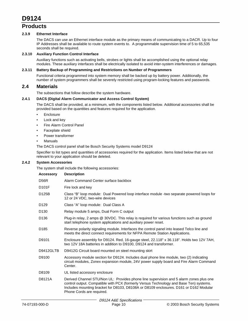
2.3.9 Ethernet Interface
The DACS can use an Ethernet interface module as the primary means of communicating to a DACR. Up to fourIP Addresses shall be available to route system events to. A programmable supervision time of 5 to 65,535seconds shall be required.
2.3.10 Auxiliary Function Control Interface
Auxiliary functions such as activating bells, strobes or lights shall be accomplished using the optional relaymodules. These auxiliary interfaces shall be electrically isolated to avoid inter-system interferences or damages.
2.3.11 Battery Backup of Programming and Restrictions on Number of Programmers
Functional criteria programmed into system memory shall be backed up by battery power. Additionally, thenumber of system programmers shall be severely restricted using program-locking features and passwords.
2.4 MaterialsThe subsections that follow describe the system hardware.
2.4.1 DACS (Digital Alarm Communicator and Access Control System)
The DACS shall be provided, at a minimum, with the components listed below. Additional accessories shall beprovided based on the quantities and features required for the application.
• Enclosure
• Lock and key
• Fire Alarm Control Panel
• Faceplate shield
• Power transformer
• Manuals
The DACS control panel shall be Bosch Security Systems model D9124
Specifier to list types and quantities of accessories required for the application. Items listed below that are notrelevant to your application should be deleted.
2.4.2 System Accessories
The system shall include the following accessories:
Accessory Description
D56R Alarm Command Center surface backbox
D101F Fire lock and key
D125B Class “B” loop module: Dual Powered loop interface module -two separate powered loops for12 or 24 VDC, two-wire devices
D129 Class “A” loop module: Dual Class A
D130 Relay module 5 amps, Dual Form C output
D136 Plug-in relay, 2 amps @ 30VDC. This relay is required for various functions such as groundstart telephone system applications and auxiliary power reset.
D185 Reverse polarity signaling module. Interfaces the control panel into leased Telco line andmeets the direct connect requirements for NFPA Remote Station Applications.
D9101 Enclosure assembly for D9124. Red, 16-gauge steel, 22.118" x 36.118". Holds two 12V 7AH,two 12V 18A batteries in addition to D9100, D9124 and transformer.
D9412GLTB D9412G Circuit board mounted on steel mounting skirt
D9100 Accessory module section for D9124. Includes dual phone line module, two (2) indicatingcircuit modules, Zonex expansion module, 24V power supply board and Fire Alarm CommandCenter.
D8109 UL listed accessory enclosure
D8121A Derived Channel STU/Non UL: Provides phone line supervision and 5 alarm zones plus onecontrol output. Compatible with PCX (formerly Versus Technology and Base Ten) systems.Includes mounting bracket for D8103, D8108A or D8109 enclosures. D161 or D162 ModularPhone Cords are required.
D9124Products
D9124 A&E Specifications© 2003 Bosch Security Systems Page 11 74-07193-000-D
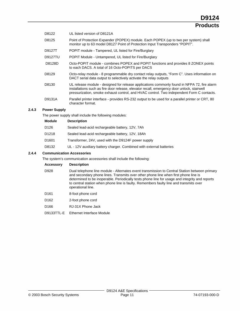
D8122 UL listed version of D8121A
D8125 Point of Protection Expander (POPEX) module. Each POPEX (up to two per system) shallmonitor up to 63 model D8127 Point of Protection Input Transponders “POPIT”.
D9127T POPIT module - Tampered, UL listed for Fire/Burglary
D9127TU POPIT Module - Untampered, UL listed for Fire/Burglary
D8128D Octo-POPIT module - combines POPEX and POPIT functions and provides 8 ZONEX pointsto each DACS. A total of 16 Octo-POPITS per DACS
D8129 Octo-relay module - 8 programmable dry contact relay outputs, “Form C”. Uses information onDACT serial data output to selectively activate the relay outputs
D8130 UL release module - designed for release applications commonly found in NFPA 72, fire alarminstallations such as fire door release, elevator recall, emergency door unlock, stairwellpressurization, smoke exhaust control, and HVAC control. Two independent Form C contacts.
D9131A Parallel printer interface - provides RS-232 output to be used for a parallel printer or CRT, 80character format.
2.4.3 Power Supply
The power supply shall include the following modules:
Module Description
D126 Sealed lead-acid rechargeable battery, 12V, 7Ah
D1218 Sealed lead-acid rechargeable battery, 12V, 18Ah
D1601 Transformer, 24V, used with the D9124F power supply
D8132 UL - 12V auxiliary battery charger. Combined with external batteries
2.4.4 Communication Accessories
The system’s communication accessories shall include the following:
Accessory Description
D928 Dual telephone line module - Alternates event transmission to Central Station between primaryand secondary phone lines. Transmits over other phone line when first phone line isdetermined to be inoperable. Periodically tests phone line for usage and integrity and reportsto central station when phone line is faulty. Remembers faulty line and transmits overoperational line.
D161 8-foot phone cord
D162 2-foot phone cord
D166 RJ-31X Phone Jack
D9133TTL-E Ethernet Interface Module
D9124Products
D9124 A&E Specifications74-07193-000-D Page 12 © 2003 Bosch Security Systems
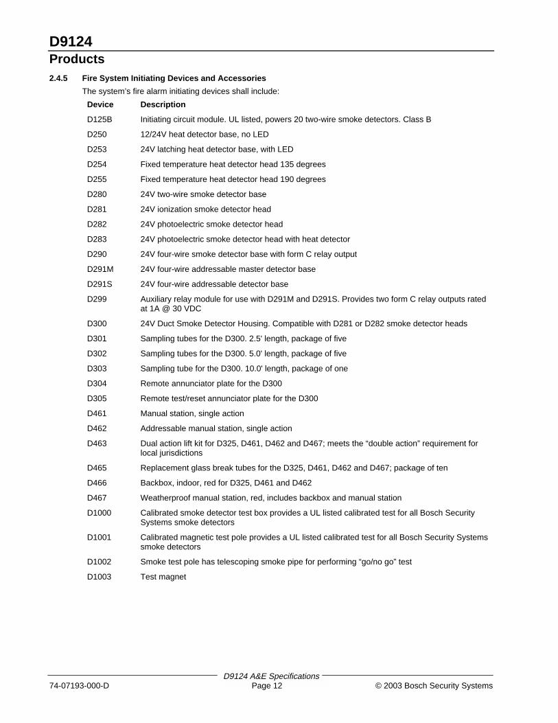
2.4.5 Fire System Initiating Devices and Accessories
The system’s fire alarm initiating devices shall include:
Device Description
D125B Initiating circuit module. UL listed, powers 20 two-wire smoke detectors. Class B
D250 12/24V heat detector base, no LED
D253 24V latching heat detector base, with LED
D254 Fixed temperature heat detector head 135 degrees
D255 Fixed temperature heat detector head 190 degrees
D280 24V two-wire smoke detector base
D281 24V ionization smoke detector head
D282 24V photoelectric smoke detector head
D283 24V photoelectric smoke detector head with heat detector
D290 24V four-wire smoke detector base with form C relay output
D291M 24V four-wire addressable master detector base
D291S 24V four-wire addressable detector base
D299 Auxiliary relay module for use with D291M and D291S. Provides two form C relay outputs ratedat 1A @ 30 VDC
D300 24V Duct Smoke Detector Housing. Compatible with D281 or D282 smoke detector heads
D301 Sampling tubes for the D300. 2.5' length, package of five
D302 Sampling tubes for the D300. 5.0' length, package of five
D303 Sampling tube for the D300. 10.0' length, package of one
D304 Remote annunciator plate for the D300
D305 Remote test/reset annunciator plate for the D300
D461 Manual station, single action
D462 Addressable manual station, single action
D463 Dual action lift kit for D325, D461, D462 and D467; meets the “double action” requirement forlocal jurisdictions
D465 Replacement glass break tubes for the D325, D461, D462 and D467; package of ten
D466 Backbox, indoor, red for D325, D461 and D462
D467 Weatherproof manual station, red, includes backbox and manual station
D1000 Calibrated smoke detector test box provides a UL listed calibrated test for all Bosch SecuritySystems smoke detectors
D1001 Calibrated magnetic test pole provides a UL listed calibrated test for all Bosch Security Systemssmoke detectors
D1002 Smoke test pole has telescoping smoke pipe for performing “go/no go” test
D1003 Test magnet
D9124Products
D9124 A&E Specifications© 2003 Bosch Security Systems Page 13 74-07193-000-D
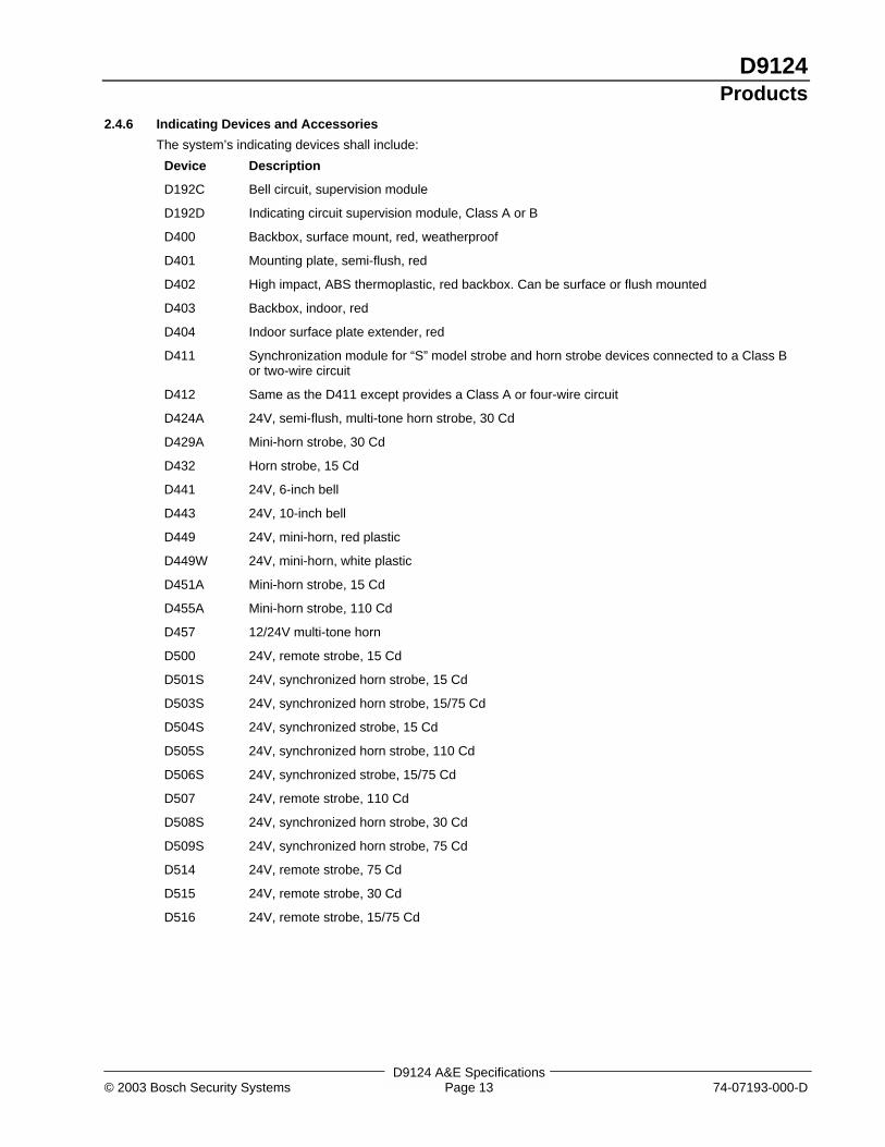
2.4.6 Indicating Devices and Accessories
The system’s indicating devices shall include:
Device Description
D192C Bell circuit, supervision module
D192D Indicating circuit supervision module, Class A or B
D400 Backbox, surface mount, red, weatherproof
D401 Mounting plate, semi-flush, red
D402 High impact, ABS thermoplastic, red backbox. Can be surface or flush mounted
D403 Backbox, indoor, red
D404 Indoor surface plate extender, red
D411 Synchronization module for “S” model strobe and horn strobe devices connected to a Class Bor two-wire circuit
D412 Same as the D411 except provides a Class A or four-wire circuit
D424A 24V, semi-flush, multi-tone horn strobe, 30 Cd
D429A Mini-horn strobe, 30 Cd
D432 Horn strobe, 15 Cd
D441 24V, 6-inch bell
D443 24V, 10-inch bell
D449 24V, mini-horn, red plastic
D449W 24V, mini-horn, white plastic
D451A Mini-horn strobe, 15 Cd
D455A Mini-horn strobe, 110 Cd
D457 12/24V multi-tone horn
D500 24V, remote strobe, 15 Cd
D501S 24V, synchronized horn strobe, 15 Cd
D503S 24V, synchronized horn strobe, 15/75 Cd
D504S 24V, synchronized strobe, 15 Cd
D505S 24V, synchronized horn strobe, 110 Cd
D506S 24V, synchronized strobe, 15/75 Cd
D507 24V, remote strobe, 110 Cd
D508S 24V, synchronized horn strobe, 30 Cd
D509S 24V, synchronized horn strobe, 75 Cd
D514 24V, remote strobe, 75 Cd
D515 24V, remote strobe, 30 Cd
D516 24V, remote strobe, 15/75 Cd
D9124Products
D9124 A&E Specifications74-07193-000-D Page 14 © 2003 Bosch Security Systems
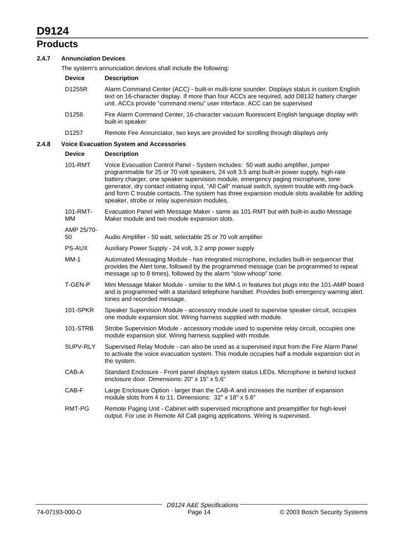
2.4.7 Annunciation Devices
The system’s annunciation devices shall include the following:
Device Description
D1255R Alarm Command Center (ACC) - built-in multi-tone sounder. Displays status in custom Englishtext on 16-character display. If more than four ACCs are required, add D8132 battery chargerunit. ACCs provide “command menu” user interface. ACC can be supervised
D1256 Fire Alarm Command Center, 16-character vacuum fluorescent English language display withbuilt-in speaker
D1257 Remote Fire Annunciator, two keys are provided for scrolling through displays only
2.4.8 Voice Evacuation System and Accessories
Device Description
101-RMT Voice Evacuation Control Panel - System includes: 50 watt audio amplifier, jumperprogrammable for 25 or 70 volt speakers, 24 volt 3.5 amp built-in power supply, high-ratebattery charger, one speaker supervision module, emergency paging microphone, tonegenerator, dry contact initiating input, “All Call” manual switch, system trouble with ring-backand form C trouble contacts. The system has three expansion module slots available for addingspeaker, strobe or relay supervision modules.
101-RMT-MM
Evacuation Panel with Message Maker - same as 101-RMT but with built-in audio MessageMaker module and two module expansion slots.
AMP 25/70-50 Audio Amplifier - 50 watt, selectable 25 or 70 volt amplifier
PS-AUX Auxiliary Power Supply - 24 volt, 3.2 amp power supply
MM-1 Automated Messaging Module - has integrated microphone, includes built-in sequencer thatprovides the Alert tone, followed by the programmed message (can be programmed to repeatmessage up to 8 times), followed by the alarm “slow whoop” tone.
T-GEN-P Mini Message Maker Module - similar to the MM-1 in features but plugs into the 101-AMP boardand is programmed with a standard telephone handset. Provides both emergency warning alerttones and recorded message.
101-SPKR Speaker Supervision Module - accessory module used to supervise speaker circuit, occupiesone module expansion slot. Wiring harness supplied with module.
101-STRB Strobe Supervision Module - accessory module used to supervise relay circuit, occupies onemodule expansion slot. Wiring harness supplied with module.
SUPV-RLY Supervised Relay Module - can also be used as a supervised input from the Fire Alarm Panelto activate the voice evacuation system. This module occupies half a module expansion slot inthe system.
CAB-A Standard Enclosure - Front panel displays system status LEDs. Microphone is behind lockedenclosure door. Dimensions: 20" x 15" x 5.6"
CAB-F Large Enclosure Option - larger than the CAB-A and increases the number of expansionmodule slots from 4 to 11. Dimensions: 32" x 18" x 5.6"
RMT-PG Remote Paging Unit - Cabinet with supervised microphone and preamplifier for high-leveloutput. For use in Remote All Call paging applications. Wiring is supervised.
D9124Products
D9124 A&E Specifications© 2003 Bosch Security Systems Page 15 74-07193-000-D
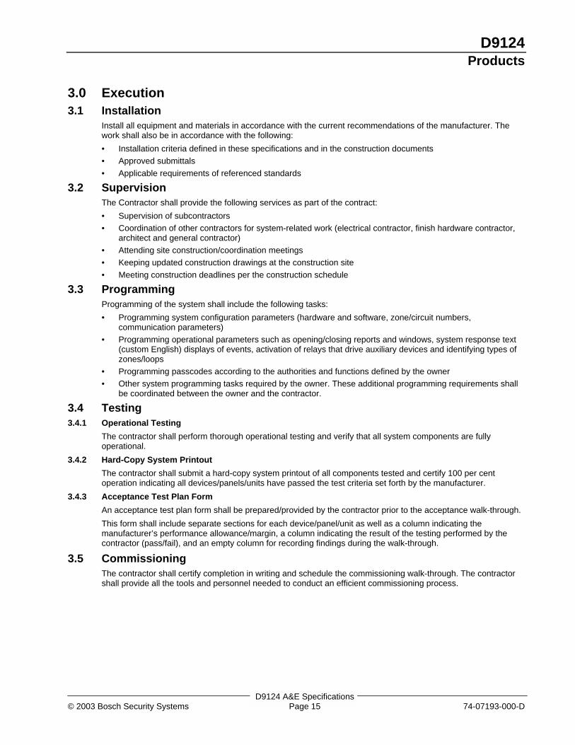
3.0 Execution3.1 Installation
Install all equipment and materials in accordance with the current recommendations of the manufacturer. Thework shall also be in accordance with the following:
• Installation criteria defined in these specifications and in the construction documents
• Approved submittals
• Applicable requirements of referenced standards
3.2 SupervisionThe Contractor shall provide the following services as part of the contract:
• Supervision of subcontractors
• Coordination of other contractors for system-related work (electrical contractor, finish hardware contractor,architect and general contractor)
• Attending site construction/coordination meetings
• Keeping updated construction drawings at the construction site
• Meeting construction deadlines per the construction schedule
3.3 ProgrammingProgramming of the system shall include the following tasks:
• Programming system configuration parameters (hardware and software, zone/circuit numbers,communication parameters)
• Programming operational parameters such as opening/closing reports and windows, system response text(custom English) displays of events, activation of relays that drive auxiliary devices and identifying types ofzones/loops
• Programming passcodes according to the authorities and functions defined by the owner
• Other system programming tasks required by the owner. These additional programming requirements shallbe coordinated between the owner and the contractor.
3.4 Testing3.4.1 Operational Testing
The contractor shall perform thorough operational testing and verify that all system components are fullyoperational.
3.4.2 Hard-Copy System Printout
The contractor shall submit a hard-copy system printout of all components tested and certify 100 per centoperation indicating all devices/panels/units have passed the test criteria set forth by the manufacturer.
3.4.3 Acceptance Test Plan Form
An acceptance test plan form shall be prepared/provided by the contractor prior to the acceptance walk-through.
This form shall include separate sections for each device/panel/unit as well as a column indicating themanufacturer’s performance allowance/margin, a column indicating the result of the testing performed by thecontractor (pass/fail), and an empty column for recording findings during the walk-through.
3.5 CommissioningThe contractor shall certify completion in writing and schedule the commissioning walk-through. The contractorshall provide all the tools and personnel needed to conduct an efficient commissioning process.

© 2003 Bosch Security Systems130 Perinton Parkway, Fairport, NY 14450-9199 USACustomer Service: (800) 289-0096; Technical Support: (888) 886-6189
74-07193-000-DA&ESpecifications
11/03D9124
Page 16 of 166