Embed Size (px)
DESCRIPTION
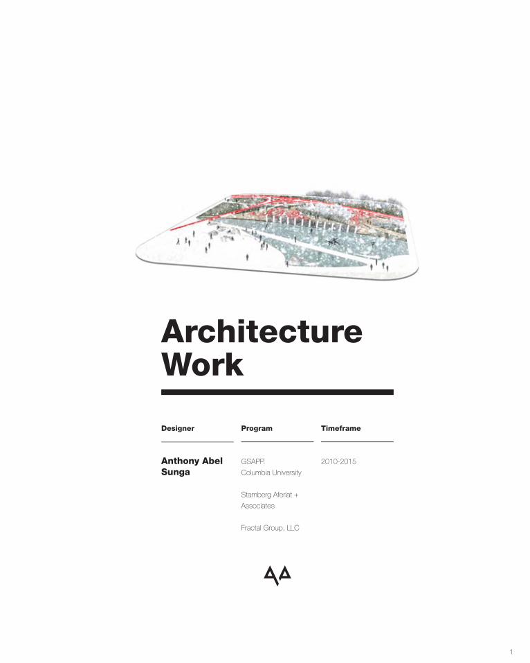
Academic and professional architectural work. GSAPP, Columbia University M.Arch, 2013
Citation preview
1
ArchitectureWork
Anthony AbelSunga
GSAPP.
Columbia University
Stamberg Aferiat +
Associates
Fractal Group, LLC
2010-2015
Designer Program Timeframe

2
3
142East EndAvenue
349Cranberry HoleRoad
T.I.N.A.*
SaguaroScottsdaleHotel
2072Cy-OlympicGames
Spatializing Sexuality
PublicMegablock
Hudson Highlands Reserve
82East MountainRoad N
4 3616
38
22 26
44 48 58
Residential
Residential
Projects
Folly
Hotel
Conservation Subdivision Residential
Urban Intervention
Urban Intervention Urbanism
4
Description
Studio
Critic(s)
Collaborator(s)
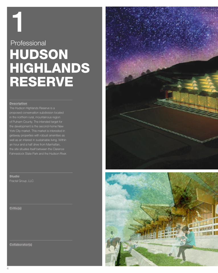
The Hudson Highlands Reserve is a
proposed conservation subdivision located
in the northern rural, mountainous region
of Putnam County. The intended target for
the development is the second-home New
York City market. This market is interested in
getaway properties with robust amenities as
well as an interest in sustainable living. Within
an hour and a half drive from Manhattan,
the site situates itself between the Clarence
Fahnestock State Park and the Hudson River.
Fractal Group, LLC
HUDSONHIGHLANDSRESERVE
Professional
1
5
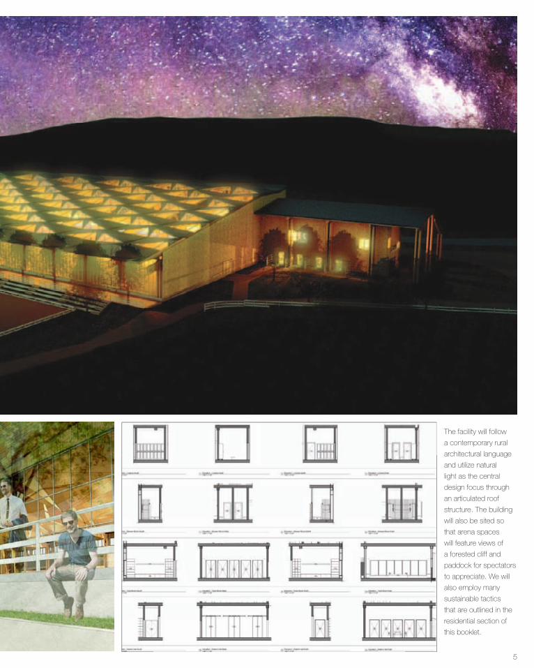
The facility will follow
a contemporary rural
architectural language
and utilize natural
light as the central
design focus through
an articulated roof
structure. The building
will also be sited so
that arena spaces
will feature views of
a forested cliff and
paddock for spectators
to appreciate. We will
also employ many
sustainable tactics
that are outlined in the
residential section of
this booklet.
6
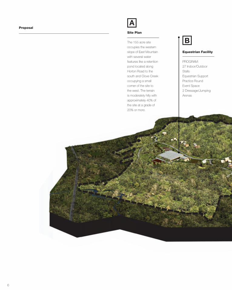
Proposal
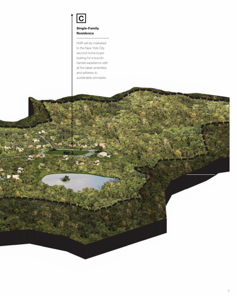
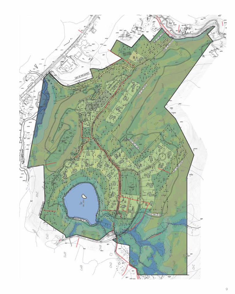
The 155 acre site
occupies the western
slope of East Mountain
with several water
features like a retention
pond located along
Horton Road to the
south and Clove Creek
occupying a small
corner of the site to
the west. The terrain
is moderately hilly with
approximately 40% of
the site at a grade of
20% or more.
Site Plan
A
Because of the region’s well recognized outdoor facilities, the area
is experiencing exceptional growth. Putnam County provides a
fantastic year-round outdoor experience with winter ski slopes as
well as summer boating and hiking trails. The Hudson Highlands
Reserve recognizes the region’s assets and strives to build upon
its foundation.
Region
To expand on the Hudson Valley’s focus on the outdoors, the
DIA Art Foundation: Beacon and Storm King Art Center calibrates
the experience of art by setting it in the landscape. Storm King
is a sprawling 500 acre site that curates over 100 sculptures in
a setting that elevates the power of sculpture and site. To carry
over the region’s emphasis on land conservation, design, and
sustainability, HHR’s mission is to develop responsible, sustainable
homes that provide a rich vacation experience while minimizing its
negative impact on the region and contributing to the sustainable
grid.
Existing Conditions
As part of the Lower Hudson
Valley region, history and
heritage is an important
aspect of the community.
The development sits across
the river from West Point
Academy and adjacent
to the historic towns of
Beacon and Garrison.
It is because of
this heritage that
the city council
enacted the
conservation
subdivision
development
plans. They
wanted to maintain
a particular
density,vernacular, and
culture. The geology of the site
is of particular interest as well. A wide
swath of the land contains
Equestrian Facility
PROGRAM:
27 Indoor/Outdoor
Stalls
Equestrian Support
Practice Round
Event Space
2 Dressage/Jumping
Arenas
B
7
Single-Family
Residence
HHR will be marketed
to the New York City
second home buyer
looking for a bucolic
hamlet experience with
all the latest amenities
and adheres to
sustainable principles.
C

8
Equestrian Facility
Program Diagram
Initial Research
and Iteration:
Solar Penetration Study Neufert’s Programming Reprogrammed
Solar Conscious
Roof: First Iteration
Based upon Neufert’s
program diagram for
equestrian centers, this
version modifies it to
include new programs
and the site.
The view of the model from the sun’s perspective
at noted time.
Altered Neufert’s program diagram to suit
contemporary conditions.
7:00 AM - 9.4%
11:00 AM - 31.3%
2:00 PM - 7.4%
4:00 PM - 0.9%
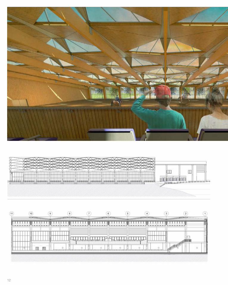
The roof will be the
driving design element
of the equestrian
center. Composed of
repetitive strips that
undulate to expose
the interior to natural
light, this expression
will be a totally internal
experience for users.
mainentrance
rest
room
kitc
hen
offic
eW
C
chan
ging
,sh
ower
lock
er ro
om
class-room A/V Room
first aid
turningarea
washarea
sadd
le ro
om
exercise room
cleaning room
stable equipmentbedding
storage
straw cutter
stablegrain silo
special fodder
fresh fodder
independenthospital stable
acco
mm
odat
ions
man
ure
wag
on
load
ing
ram
p
fodd
er
prep
tethering area
sta� room
farrier’s room
mounting
jumps
spectators
spec
tato
rsju
dges
st
and
hors
e bo
xes
lung
e ar
ea
outdoorriding areaindoor
riding areapark
ing
Load
ing
riding areasdriving paths
Support
Work
Social
Training
Visual Connection Indoor
OutdoorPeople Only
People and Horses
RR
kitchen
office
cafe
flex space
foyer
A/V Room
stable
practiceround
mounting
spectators
spectators
spec
tato
rsju
dges
’ sta
nd
outdoorriding area
parking
mainentrance
Load
ing
Load
ing
indoorriding area
WC
changing,shower
locker room
saddle room
tack
mech.equip. sta�
farrier
turningarea
turningarea
riding areasdriving paths
riding areasdriving paths
washarea
beddingstorage
straw cutter
grain silo
special fodder
fresh fodder
fodder prep
turningarea
fodder prep
short-termfeed
short-termfeed
loading ramp
stable equipment
manure wagon
class-room
Neufert Program Diagram HHR Program Diagramm
ain
entr
ance
restroom kitchenofficeWC
changing,shower
locker room
clas
s-ro
omA
/V R
oom
first
aid
turn
ing
area
was
har
ea
saddle room
exer
cise
room
clea
ning
room
stab
le
equi
pmen
tbe
ddin
gst
orag
e
stra
w c
utte
r
stab
legr
ain
silo
spec
ial
fodd
er
fres
h fo
dder
inde
pend
ent
hosp
ital s
tabl
e
accommodations
manure wagon
loading ramp
fodder prep
teth
erin
g ar
ea
sta�
room
farr
ier’s
room
mou
ntin
g
jum
ps
spec
tato
rs
spectatorsjudges stand
horse boxes
lunge area
outd
oor
ridin
g ar
eain
door
ridin
g ar
ea
parkingLoading
ridin
g ar
eas
driv
ing
path
s
Supp
ort
Wor
k
Soci
al
Trai
ning
Visu
al C
onne
ctio
nIn
door
Out
door
Peop
le O
nly
Peop
le a
nd H
orse
s
RR
kitc
hen
offic
e
cafe
flex
spac
e
foye
r
A/V
Roo
m
stab
le prac
tice
roun
d
mou
ntin
g
spec
tato
rs
spec
tato
rs
spectatorsjudges’ stand
outd
oor
ridin
g ar
ea
park
ing
mai
nen
tran
ce
Loading
Loading
indo
orrid
ing
area
WC
chan
ging
,sh
ower
lock
er ro
om
sadd
le ro
om
tack
mec
h.eq
uip.
sta�
farr
ier
turn
ing
area
turn
ing
area
ridin
g ar
eas
driv
ing
path
srid
ing
area
sdr
ivin
g pa
ths
was
har
ea
bedd
ing
stor
age
stra
w c
utte
r
grai
n si
lo
spec
ial
fodd
er
fres
h fo
dder
fodd
er p
rep
turn
ing
area
fodd
er p
rep
shor
t-ter
mfe
edsh
ort-t
erm
feed
load
ing
ram
p
stab
le
equi
pmen
t
man
ure
wag
on
clas
s-ro
om
Neu
fert
Pro
gram
Dia
gram
HH
R Pr
ogra
m D
iagr
am
main
entrance
restroomkitchen officeWC
changing,shower
locker room
class-room
A/V Room
first aid
turningarea
wash
area
saddle room
exercise room
cleaning room
stable equipm
entbeddingstorage
straw cutter
stablegrain silo
special fodder
fresh fodder
independenthospital stable
accommodations
manure wagon
loading ramp
fodder prep
tethering area
sta� room
farrier’s room
mounting
jumps
spectators
spectators judges stand
horse boxes
lunge area
outdoorriding area
indoorriding area
parking Loading
riding areasdriving paths
Support
Work
Social
Training
Visual ConnectionIndoor
Outdoor
People Only
People and Horses
RR
kitchen
office
cafe
flex space
foyer
A/V Room
stablepracticeround
mounting
spectators
spectators
spectators judges’ stand
outdoorriding area
parking
main
entrance
Loading
Loading
indoorriding area
WC
changing,show
er
locker room
saddle room
tack
mech.
equip.sta�
farrier
turningarea
turningarea
riding areasdriving paths
riding areasdriving paths
wash
area
beddingstorage
straw cutter
grain silo
special fodder
fresh fodder
fodder prep
turningarea
fodder prep
short-termfeed
short-termfeed
loading ram
p
stable equipm
ent
manure
wagon
class-room
Neufert Program
Diagram
HH
R Program D
iagram
PartA
7:00 AM9.4%
31.3%
7.4% 5.7% 4.9% 4.9% 8.8%
0.3% 0.06% 0.1% 0.1% 0.4%
31.7% 26.6% 23.1% 30.0%
0.2% 0.02% 0.03% 0.09%
11:00 AM
2:00 PM
4:00 PM
A B C D E
7:00 AM9.4%
31.3%
7.4% 5.7% 4.9% 4.9% 8.8%
0.3% 0.06% 0.1% 0.1% 0.4%
31.7% 26.6% 23.1% 30.0%
0.2% 0.02% 0.03% 0.09%
11:00 AM
2:00 PM
4:00 PM
A B C D E
7:00 AM9.4%
31.3%
7.4% 5.7% 4.9% 4.9% 8.8%
0.3% 0.06% 0.1% 0.1% 0.4%
31.7% 26.6% 23.1% 30.0%
0.2% 0.02% 0.03% 0.09%
11:00 AM
2:00 PM
4:00 PM
A B C D E
7:00 AM9.4%
31.3%
7.4% 5.7% 4.9% 4.9% 8.8%
0.3% 0.06% 0.1% 0.1% 0.4%
31.7% 26.6% 23.1% 30.0%
0.2% 0.02% 0.03% 0.09%
11:00 AM
2:00 PM
4:00 PM
A B C D E
107
1 SW View4 NE View
1 SW View4 NE View
Roof Plan
The roof will be the
driving design element
of the equestrian
center. Composed of
repetitive strips that
undulate to expose
the interior to natural
light, this expression
will be a totally internal
experience for users.
107
1 SW View4 NE View
1 SW View4 NE View
Roof Plan
The roof will be the
driving design element
of the equestrian
center. Composed of
repetitive strips that
undulate to expose
the interior to natural
light, this expression
will be a totally internal
experience for users.
9
10
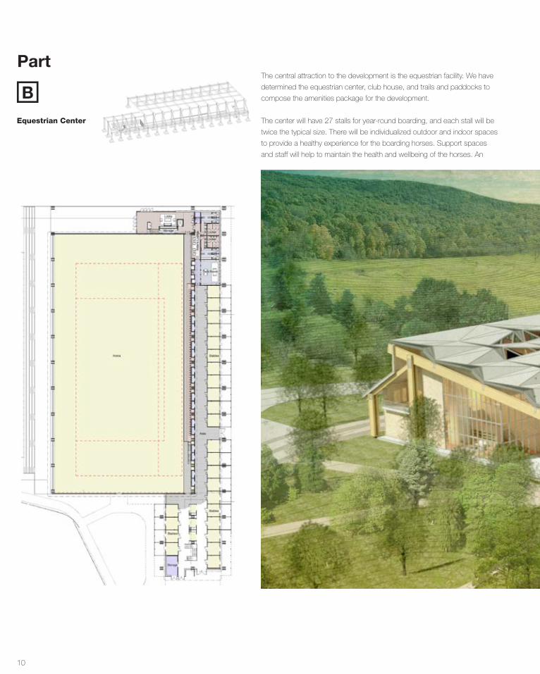
Equestrian Center
Part
BThe central attraction to the development is the equestrian facility. We have
determined the equestrian center, club house, and trails and paddocks to
compose the amenities package for the development.
The center will have 27 stalls for year-round boarding, and each stall will be
twice the typical size. There will be individualized outdoor and indoor spaces
to provide a healthy experience for the boarding horses. Support spaces
and staff will help to maintain the health and wellbeing of the horses. An
11
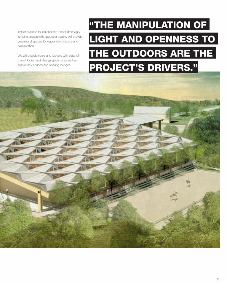
indoor practice round and two indoor dressage/
jumping arenas with spectator seating will provide
year-round spaces for equestrian practice and
presentation.
We will provide riders and jockeys with state-of-
the-art locker and changing rooms as well as
ample tack spaces and relaxing lounges.
“THE MANIPULATION OF
LIGHT AND OPENNESS TO
THE OUTDOORS ARE THE
PROJECT’S DRIVERS.”
12
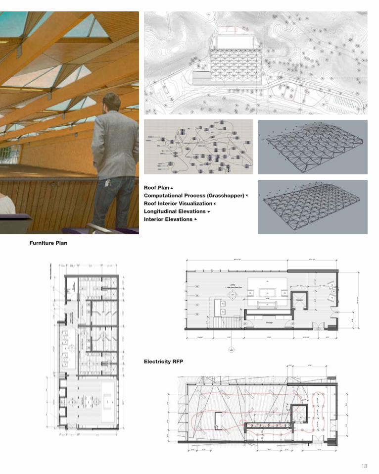
13
Roof Plan
Computational Process (Grasshopper)
Roof Interior Visualization
Longitudinal Elevations
Interior Elevations
Furniture Plan
Electricity RFP
14
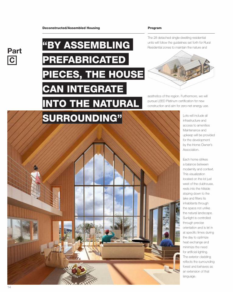
Deconstructed/Assembled Housing Program
The 28 detached single-dwelling residential
units will follow the guidelines set forth for Rural
Residential zones to maintain the nature and
aesthetics of the region. Furthermore, we will
pursue LEED Platinum certification for new
construction and aim for zero-net energy use.
Part“BY ASSEMBLING
PREFABRICATED
PIECES, THE HOUSE
CAN INTEGRATE
INTO THE NATURAL
SURROUNDING”
C
Lots will include all
infrastructure and
access to amenities
Maintenance and
upkeep will be provided
for the development
by the Home Owner’s
Association.
Each home strikes
a balance between
modernity and context.
This visualization
located on the lot just
west of the clubhouse,
rests into the hillside
sloping down to the
lake and filters its
inhabitants through
the space not unlike
the natural landscape.
Sunlight is controlled
through precise
orientation and is let in
at specific times during
the day to optimize
heat exchange and
minimize the need
for artificial lighting.
The exterior cladding
reflects the surrounding
forest and behaves as
an extension of that
language.
15
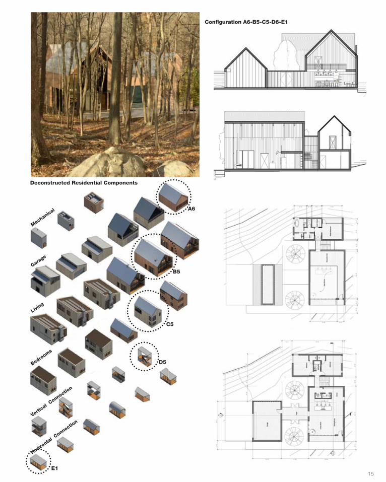
Deconstructed Residential Components
Configuration A6-B5-C5-D6-E1
A6
B5
C5
Garage
Living
Bedrooms
Vertical C
onnection
Horizontal C
onnection
Mechanical
E1
D5
16
T.I.N.A.*
Description
Studio
Critic(s)
Collaborator(s)
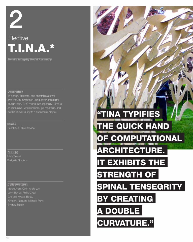
To design, fabricate, and assemble a small
architectural installation using advanced digital
design tools, CNC milling, and ingenuity. Time is
an imperative, where instinct, gut reactions, and
quick turnover is key to a successful project.
Tensile Integrity Nodal Assembly
Fast Pace | Slow Space
Mark Bearak
Bridgette Borders
Nicole Allen, Collin Anderson
John Barrett, Phillip Crupi
Chelsea Hyduk, Bo Liu
Kimberly Nguyen, Michelle Park
Sydney Talcott
Elective
2
“TINA TYPIFIES
THE QUICK HAND
OF COMPUTATIONAL
ARCHITECTURE.
IT EXHIBITS THE
STRENGTH OF
SPINAL TENSEGRITY
BY CREATING
A DOUBLE
CURVATURE.”
17
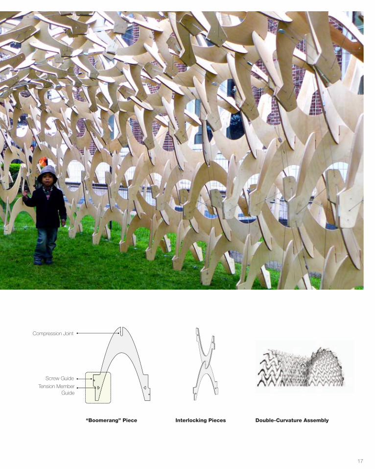
Compression Joint
Screw Guide
Tension Member Guide
TINA*
compression joint
screw guide
tension member guide
shape determined by nesting pattern and member to member
connection
Double-Curvature Assembly“Boomerang” Piece Interlocking Pieces
18
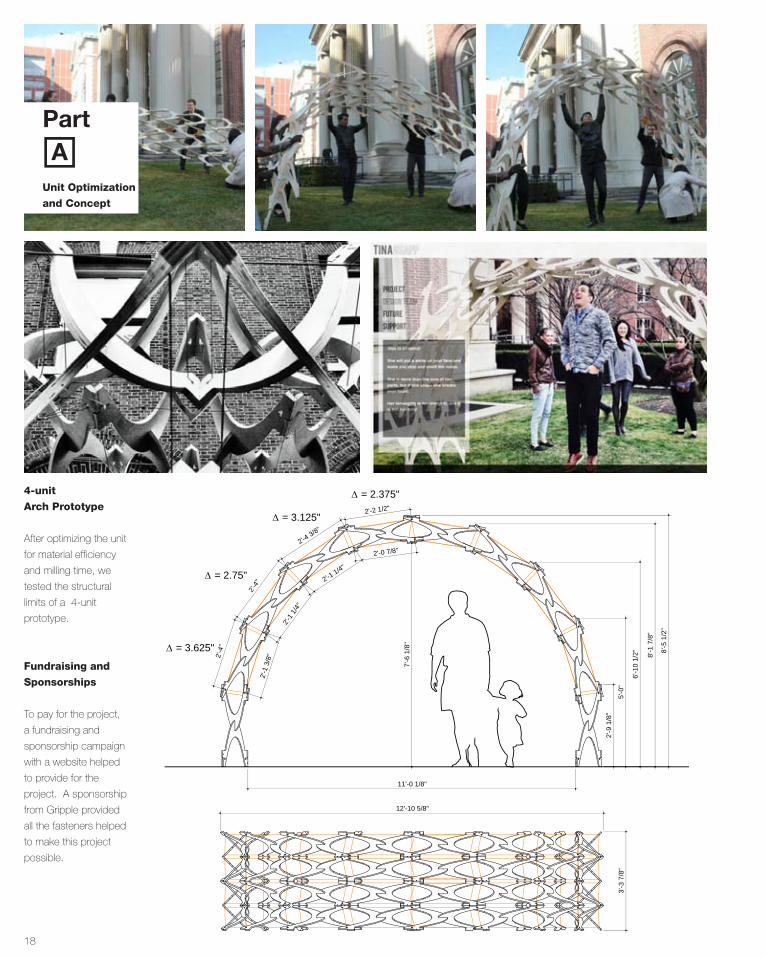
After optimizing the unit
for material efficiency
and milling time, we
tested the structural
limits of a 4-unit
prototype.
4-unit
Arch Prototype
Fundraising and
Sponsorships
To pay for the project,
a fundraising and
sponsorship campaign
with a website helped
to provide for the
project. A sponsorship
from Gripple provided
all the fasteners helped
to make this project
possible.
APart
Unit Optimization
and Concept
TINA*
130402 FPSS TINA Mockup1/2” = 1’-0”
3'-3
7/8
"
11'-0 1/8"
12'-10 5/8"
6'-1
0 1/
2"
5'-0
"
2'-9
1/8
"
∆ = 3.625" 8'-5
1/2
"
8'-1
7/8
"
∆ = 2.375"
7'-6
1/8
"
2'-0 7/8"
2'-1 1/4"
2'-2 1/2"
2'-4 3/8"
2'-4"
2'-1 1
/4"
2'-1
3/8
"2'-4
"
∆ = 2.75"
∆ = 3.125"
TINA*
130402 FPSS TINA Mockup1/2” = 1’-0”
3'-3
7/8
"
11'-0 1/8"
12'-10 5/8"
6'-1
0 1/
2"
5'-0
"
2'-9
1/8
"
∆ = 3.625" 8'-5
1/2
"
8'-1
7/8
"
∆ = 2.375"
7'-6
1/8
"
2'-0 7/8"
2'-1 1/4"
2'-2 1/2"
2'-4 3/8"
2'-4"
2'-1 1
/4"
2'-1
3/8
"2'-4
"
∆ = 2.75"
∆ = 3.125"
19
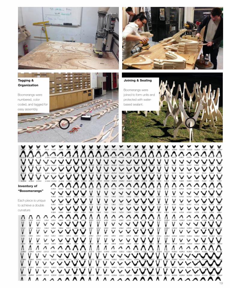
Inventory of
“Booomerangs”
Each piece is unique
to achieve a double
curvature
Tagging &
Organization
Boomerangs were
numbered, color
coded, and tagged for
easy assembly.
Joining & Sealing
Boomerangs were
joined to form units and
protected with water-
based sealant.
20
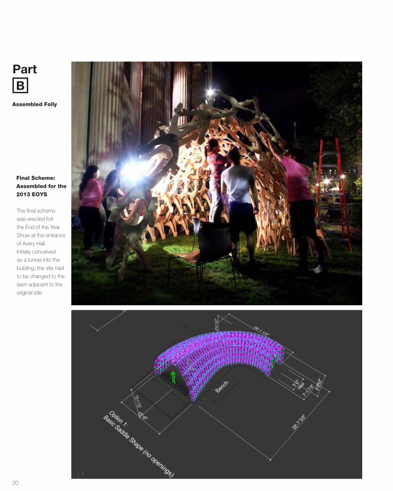
The final scheme
was erected fort
the End of the Year
Show at the entrance
of Avery Hall.
Initially conceived
as a tunnel into the
building, the site had
to be changed to the
lawn adjacent to the
original site.
Final Scheme:
Assembled for the
2013 EOYS
PartB
Assembled Folly
21
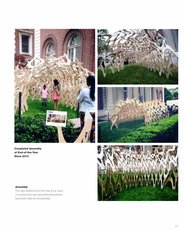
Completed Assembly
at End-of-the-Year
Show 2013
Assembly
The night before End-of-the-Year show. Each
4-member arch was assembled beforehand,
leaving the night for full assembly.
22
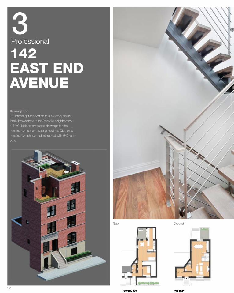
142EAST END AVENUE
Description
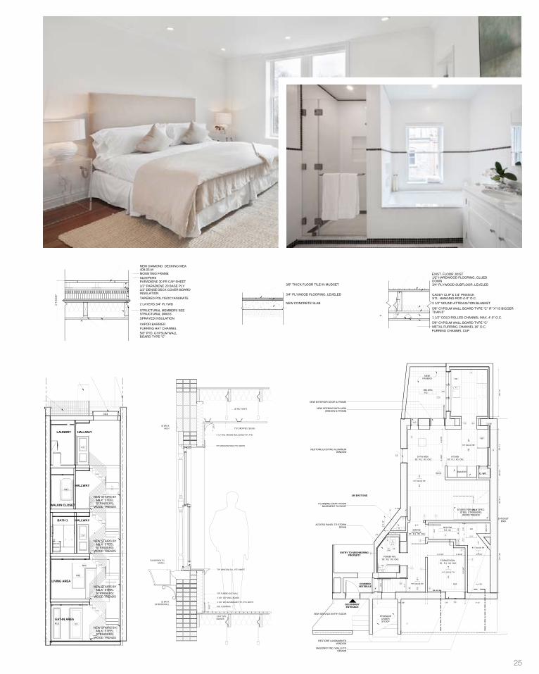
Full interior gut renovation to a six story single-
family brownstone in the Yorkville neighborhood
of NYC. Helped produced drawings for the
construction set and change orders. Observed
construction phase and interacted with GCs and
subs.
Sub Ground
Professional3
First FloorGarden Floor First FloorGarden Floor
23
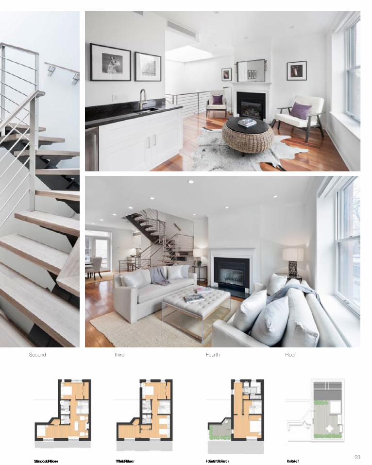
Second Third Fourth Roof
Third FloorSecond Floor Third FloorSecond Floor RoofFourth Floor RoofFourth Floor
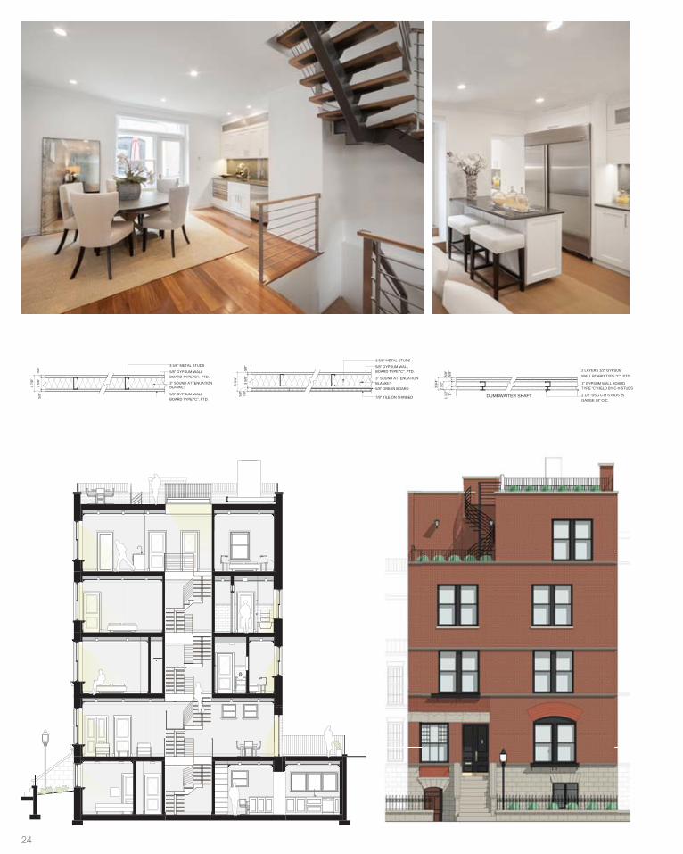
24 ELEVATIONS PAGE 11
3 5/
8"
5/8" GYPSUM WALLBOARD TYPE "C", PTD.
3 5/8" METAL STUDS
5/8" GREEN BOARD
7/8" TILE ON THINBED
3" SOUND ATTENUATIONBLANKET
5/8"
7/8"
5 3/
4"
5/8"
5/8"
3 5/
8"
5/8" GYPSUM WALLBOARD TYPE "C", PTD.
3 5/8" METAL STUDS
5/8" GYPSUM WALLBOARD TYPE "C", PTD.
3" SOUND ATTENUATIONBLANKET
5/8"
4 7/
8"
2 LAYERS 1/2" GYPSUMWALL BOARD TYPE "C", PTD.
2 1/2" USG C-H STUDS 25GAUGE 24" O.C.
1" GYPSUM WALL BOARDTYPE "C" HELD BY C-H STUDS2
1/2"
5/8"
5/8"
1"
3 3/
4"
DUMBWAITER SHAFT1 1/
2"
3 5/
8"
5/8" GYPSUM WALLBOARD TYPE "C", PTD.
3 5/8" METAL STUDS
5/8" GREEN BOARD
7/8" TILE ON THINBED
3" SOUND ATTENUATIONBLANKET
5/8"
7/8"
5 3/
4"
5/8"
5/8"
3 5/
8"
5/8" GYPSUM WALLBOARD TYPE "C", PTD.
3 5/8" METAL STUDS
5/8" GYPSUM WALLBOARD TYPE "C", PTD.
3" SOUND ATTENUATIONBLANKET
5/8"
4 7/
8"
2 LAYERS 1/2" GYPSUMWALL BOARD TYPE "C", PTD.
2 1/2" USG C-H STUDS 25GAUGE 24" O.C.
1" GYPSUM WALL BOARDTYPE "C" HELD BY C-H STUDS2
1/2"
5/8"
5/8"
1"
3 3/
4"
DUMBWAITER SHAFT1 1/
2"
25
5 3/8"
4 1/2"
5 3/8” WD. BASEBOARD TYP., PTD. WHITE
WD. FLOORING
3 5/8” MTL. RUNNER
5 3/8” GYP. WALL BOARD
TYP. FURRED OUT WALL
TYP. WINDOW SILL, PTD. WHITE
TYP. WINDOW TRIM, PTD. WHITE
4 1/2” WD. CROWN MOULDING TYP., PTD.
TYP. DROPPED CEILING
(E) WD. JOISTS
FLOWERBOX TO MATCH
(E) BRICK EXTERIOR WALL
(E) BRICK ARCH
2 LAYERS OF 5/8"GYPSUM WALLBOARD TYPE "C", PTD.
3 5/8" METAL STUDS
2 LAYERS OF 5/8"GYPSUM WALLBOARD TYPE "C", PTD.
3" SOUND ATTENUATIONBLANKET
5/8"
5/8"
3 5/
8"5/
8"5/
8"
6 1/
8"
3 5/
8"
5/8" GYPSUM WALLBOARD TYPE "C", PTD.
3 5/8" METAL STUDS
5/8" GREEN BOARD7/8" TILE ON THINBED
3" SOUND ATTENUATION BLANKET
5/8"
7/8"
5 3/
4"
5/8"
3 5/8" METAL STUDS
2 LAYERS OF 5/8"GYPSUM WALLBOARD TYPE "C", PTD.
3" SOUND ATTENUATIONBLANKET
MECHANICALSHAFT
EXISTING MASONRYWALL
5/8"
5/8"
3 5/
8"
4 7/
8"T.
B.D
. MECHANICALSHAFT
2 1/2" METAL STUDS
5/8" GYPSUM WALLBOARD TYPE "C", PTD.
2" SOUND ATTENUATIONBLANKET
EXISTING EXTERIORMASONRY WALL
5/8"
2 1/
2"
3 1/
8"
5/8"
3 5/
8"
5/8" GYPSUM WALLBOARD TYPE "C", PTD
3 5/8" METAL STUDS
5/8" GYPSUM WALLBOARD TYPE "C", PTD.
3" SOUND ATTENUATIONBLANKET
5/8"
4 7/
8"
1'-4
31/
32"
NEW CONCRETE SLAB
3/8" THICK FLOOR TILE IN MUDSET
3/4" PLYWOOD FLOORING, LEVELED
EXIST. FLOOR JOIST
FURRING CHANNEL CUPMETAL FURRING CHANNEL 16" O.C.5/8" GYPSUM WALL BOARD TYPE "C"1 1/2" COLD ROLLED CHANNEL MAX. 4'-0" O.C.
2 1/2" SOUND ATTENUATION BLANKET
CADDY CLIP & 1/4" PENSILESTL. HANGING ROD 4'-0" O.C.
5/8" GYPSUM WALL BOARD TYPE "C" IF "X" IS BIGGERTHAN 6"
X
3/4" PLYWOOD SUBFLOOR, LEVELED
1/2" HARDWOOD FLOORING, GLUEDDOWN
5/8" GYPSUM WALLBOARD TYPE "C", PTD.
EXISTINGMASONRY WALL
5/8"
2 LAYERS 1/2" GYPSUMWALL BOARD TYPE "C",PTD.
2 1/2" USG C-H STUDS 25GAUGE 24" O.C.
1" GYPSUM WALL BOARDTYPE "C" HELD IN PLACEBY C-H STUDS2
1/2"
5/8"
5/8"
1"
3 3/
4"
DUMBWAITER SHAFT1 1/
2"
3 5/8" METAL STUDS
5/8" GREEN BOARD7/8" TILE ON THINBED
3" SOUND ATTENUATION BLANKET
5/8"
7/8"
5/8" GREEN BOARD7/8" TILE ON THINBED
6 5/
8"
7/8"
5/8"
3 5/
8"
2 1/2" METAL STUDS
2" SOUND ATTENUATIONBLANKET
EXISTING EXTERIORWALL
5/8" GREEN BOARD7/8" TILE ON THINBED7/
8"5/
8"2
1/2"
4"
3 5/8" METAL STUDS
5/8" GYPSUM WALLBOARD TYPE "C", PTD.
3" SOUND ATTENUATIONBLANKET
EXISTING MASONRYWALL
5/8"
3 5/
8"T.
B.D
.
CAVITY
4 1/
4"
3 5/
8"
3 5/8" METAL STUDS
5/8" GREEN BOARD7/8" TILE ON THINBED
3" SOUND ATTENUATION BLANKET
5/8"
7/8"
5 1/
8"
EXISTING MASONRYWALL
5 5/8" METAL STUDS
5/8" GREEN BOARD7/8" TILE ON THINBED
5" SOUND ATTENUATION BLANKET
5/8"
7/8"
5/8" GREEN BOARD7/8" TILE ON THINBED
8 5/
8"
7/8"
5/8"
5 5/
8"
5 5/8" METAL STUDS
5/8" GREEN BOARD
7/8" TILE ON THINBED
5" SOUND ATTENUATION BLANKET
5/8"
7/8"
EXISTING EXTERIORMASONRY WALL
5 5/
8"
7 1/
8"
5 5/8" METAL STUDS
2 LAYERS OF 5/8"GYPSUM WALLBOARD TYPE "C", PTD.
5" SOUNDATTENUATIONBLANKET
MECHANICALSHAFT
EXISTING MASONRYWALL
5/8"
5/8"
5 5/
8"
6 7/
8"T.
B.D
. MECHANICALSHAFT
2 1/2" METAL STUDS
3/8" GYPSUM WALLBOARD TYPE "C", PTD.
2" SOUND ATTENUATIONBLANKET
EXISTING EXTERIORMASONRY WALL
3/8"
1 5/
8"
2"
2 1/2" METAL STUDS
5/8" GYPSUM WALLBOARD TYPE "C", PTD.
2" SOUND ATTENUATIONBLANKET
EXISTING EXTERIORMASONRY WALL
5/8"
1 5/
8"
2 1/
4"
7/8" METAL FURRING STRIP,CHICAGO BAR
5/8" GYPSUM WALLBOARD TYPE "C", PTD.
EXISTING EXTERIORMASONRY WALL
5/8"
7/8"
1 1/
2"
Fractal Construction LLC
DRAWN BY:
DWG NO.:
SCALE:
DRAWING TITLE:
SEAL & SIGNATURE:
PROJECT NO.:
DATE:
PROJECT:
ARCHITECT OF RECORD:
CADO FILE No.
DESIGN ARCHITECT:
315 East 91st St.New York, NY 10128O: 212.228.5617 F: 212.228.5618
N
STRUCTURAL ENGINEER:
MEP ENGINEER:
© 2010 FRACTAL CONSTRUCTION LLC, ALL RIGHTS RESERVED
THIS DRAWING AND ALL GRAPHIC AND WRITTEN MATERIAL CONTAINED HEREIN,CONSTITUTES THE ORIGINAL AND UNPUBLISHED WORK OF FRACTAL CONSTRUCTION
LLC AND MAY NOT BE COPIED, DISTRIBUTED OR USED IN WHOLE OR IN PART.WITHOUT EXPRESSED WRITTEN PERMISSION FROM FRACTAL CONSTRUCTION LLC.
NOTES/LEGENDS:
DRAWING ISSUE
Drawing Description Issue DateIssue Number
Code Consultants/ Hunt Architects440 Park Ave South, PH, New York, NY 10016
O: 212.447.9191 F: 212.545.9777
MURRAY ENGINEERING, P.C.307 7th Avenue, Suite 1001; New York, NY 10001
O: 212.741.1102 F: 212.741.1104
CGM ENGINEERING180 South Broadway, Suite 300 ; White Plains, NY 10605
O: 914.949.5112 F: 914.949.5116
Landmarks Submission 2011-12-011Landmarks Re-Submission 2012-01-202BID Set Submission 2012-03-203Landmarks Re-Submission 2012-04-094Permit Set5 2012-05-08
REVISIONS:
Construction Set6 2013-05-19As Built Set7 2014-03-25
1 1/2" = 1'-0"
1
FLOOR/WALL TYPES
11/07/11
Author
A- 900.01
1006
142 EAST END
NEW YORK, NY 10128
1 1/2" = 1'-0"2 INTERIOR PARTITION - 6 1/8"
1 1/2" = 1'-0"3 TILE PARTITION ONE SIDE - 5 3/4"
1 1/2" = 1'-0"7 MECHANICAL SHAFT WALL - 4 7/8"
1 1/2" = 1'-0"5 FURRED WALL ON EXIST. WALL - 3 1/8"
1 1/2" = 1'-0"1 INTERIOR PARTITION - 4 7/8"
1 1/2" = 1'-0"14. Terrace Detail
MOUNTING FRAME
NEW DIAMOND DECKING MEA409-03-M
TAPERED POLYISOCYANURATE
2 LAYERS 3/4" PLYWD
STRUCTURAL MEMBERS SEESTRUCTURAL DWGSSPRAYED INSULATION
FURRING HAT CHANNELVAPOR BARRIER
5/8" PTD. GYPSUM WALLBOARD TYPE "C"
1 1/2" = 1'-0"15. Cellar Concrete Floor
1 1/2" = 1'-0"16. Floor Detail
PERMIT
ANSI/UL 2631 H FIRE RATED
ANSI/UL 263
2 H FIRE RATED
ANSI/UL 2631 H FIRE RATED
ANSI/UL 2631 H FIRE RATED
ANSI/UL 2632 H FIRE RATED
SLEEPERS
1/2" DENSE DECK COVER BOARDINSULATION
1/2" PARADIENE 20 BASE PLYPARADIENE 30 FR CAP SHEET
1 1/2" = 1'-0"8FLY BY SHEET ROCK ON EXIST. WALL -5/8"
1 1/2" = 1'-0"9 DUMBWAITER SHAFT WALL - 3 3/4" 1 1/2" = 1'-0"4 TILE PARTITION TWO SIDES - 6 5/8"
1 1/2" = 1'-0"12 FURRED WALL WITH TILE - 4"
ANSI/UL 2631 H FIRE RATED
UL 263 U415,SYSTEM B
2 H FIRE RATED
1 1/2" = 1'-0"1.1 INTERIOR PARTITION - 4 1/4"ANSI/UL 2631 H FIRE RATED
1 1/2" = 1'-0"3.1 TILE PARTITION ONE SIDE - 5 1/8"ANSI/UL 2631 H FIRE RATED
1 1/2" = 1'-0"4.1 TILE PARTITION TWO SIDES - 8 5/8"ANSI/UL 2631 H FIRE RATED
1 1/2" = 1'-0"6 FURRED WALL WITH TILE - 7 1/8"ANSI/UL 2631 H FIRE RATED
1 1/2" = 1'-0"7.1 MECHANICAL SHAFT WALL - 6 7/8"ANSI/UL 2632 H FIRE RATED
ANSI/UL 2631 H FIRE RATED
1 1/2" = 1'-0"10 FURRED WALL ON EXIST. WALL - 2"ANSI/UL 2631 H FIRE RATED
1 1/2" = 1'-0"10.1 FURRED WALL ON EXIST. WALL - 2 1/4"
ANSI/UL 2631 H FIRE RATED
ANSI/UL 2631 H FIRE RATED
1 1/2" = 1'-0"11 FURRED WALL ON EXIST. WALL - 1 1/2"ANSI/UL 2631 H FIRE RATED
1
1
REVISION SCHEDULE
Rev. # Rev. Desc. Rev. Date
12-10-4102teS tliuB-sA1
2 LAYERS OF 5/8"GYPSUM WALLBOARD TYPE "C", PTD.
3 5/8" METAL STUDS
2 LAYERS OF 5/8"GYPSUM WALLBOARD TYPE "C", PTD.
3" SOUND ATTENUATIONBLANKET
5/8"
5/8"
3 5/
8"5/
8"5/
8"
6 1/
8"
3 5/
8"
5/8" GYPSUM WALLBOARD TYPE "C", PTD.
3 5/8" METAL STUDS
5/8" GREEN BOARD7/8" TILE ON THINBED
3" SOUND ATTENUATION BLANKET
5/8"
7/8"
5 3/
4"
5/8"
3 5/8" METAL STUDS
2 LAYERS OF 5/8"GYPSUM WALLBOARD TYPE "C", PTD.
3" SOUND ATTENUATIONBLANKET
MECHANICALSHAFT
EXISTING MASONRYWALL
5/8"
5/8"
3 5/
8"
4 7/
8"T.
B.D
. MECHANICALSHAFT
2 1/2" METAL STUDS
5/8" GYPSUM WALLBOARD TYPE "C", PTD.
2" SOUND ATTENUATIONBLANKET
EXISTING EXTERIORMASONRY WALL
5/8"
2 1/
2"
3 1/
8"
5/8"
3 5/
8"
5/8" GYPSUM WALLBOARD TYPE "C", PTD
3 5/8" METAL STUDS
5/8" GYPSUM WALLBOARD TYPE "C", PTD.
3" SOUND ATTENUATIONBLANKET
5/8"
4 7/
8"
1'-4
31/
32"
NEW CONCRETE SLAB
3/8" THICK FLOOR TILE IN MUDSET
3/4" PLYWOOD FLOORING, LEVELED
EXIST. FLOOR JOIST
FURRING CHANNEL CUPMETAL FURRING CHANNEL 16" O.C.5/8" GYPSUM WALL BOARD TYPE "C"1 1/2" COLD ROLLED CHANNEL MAX. 4'-0" O.C.
2 1/2" SOUND ATTENUATION BLANKET
CADDY CLIP & 1/4" PENSILESTL. HANGING ROD 4'-0" O.C.
5/8" GYPSUM WALL BOARD TYPE "C" IF "X" IS BIGGERTHAN 6"
X
3/4" PLYWOOD SUBFLOOR, LEVELED
1/2" HARDWOOD FLOORING, GLUEDDOWN
5/8" GYPSUM WALLBOARD TYPE "C", PTD.
EXISTINGMASONRY WALL
5/8"
2 LAYERS 1/2" GYPSUMWALL BOARD TYPE "C",PTD.
2 1/2" USG C-H STUDS 25GAUGE 24" O.C.
1" GYPSUM WALL BOARDTYPE "C" HELD IN PLACEBY C-H STUDS2
1/2"
5/8"
5/8"
1"
3 3/
4"
DUMBWAITER SHAFT1 1/
2"
3 5/8" METAL STUDS
5/8" GREEN BOARD7/8" TILE ON THINBED
3" SOUND ATTENUATION BLANKET
5/8"
7/8"
5/8" GREEN BOARD7/8" TILE ON THINBED
6 5/
8"
7/8"
5/8"
3 5/
8"
2 1/2" METAL STUDS
2" SOUND ATTENUATIONBLANKET
EXISTING EXTERIORWALL
5/8" GREEN BOARD7/8" TILE ON THINBED7/
8"5/
8"2
1/2"
4"
3 5/8" METAL STUDS
5/8" GYPSUM WALLBOARD TYPE "C", PTD.
3" SOUND ATTENUATIONBLANKET
EXISTING MASONRYWALL
5/8"
3 5/
8"T.
B.D
.
CAVITY
4 1/
4"
3 5/
8"
3 5/8" METAL STUDS
5/8" GREEN BOARD7/8" TILE ON THINBED
3" SOUND ATTENUATION BLANKET
5/8"
7/8"
5 1/
8"
EXISTING MASONRYWALL
5 5/8" METAL STUDS
5/8" GREEN BOARD7/8" TILE ON THINBED
5" SOUND ATTENUATION BLANKET
5/8"
7/8"
5/8" GREEN BOARD7/8" TILE ON THINBED
8 5/
8"
7/8"
5/8"
5 5/
8"
5 5/8" METAL STUDS
5/8" GREEN BOARD
7/8" TILE ON THINBED
5" SOUND ATTENUATION BLANKET
5/8"
7/8"
EXISTING EXTERIORMASONRY WALL
5 5/
8"
7 1/
8"
5 5/8" METAL STUDS
2 LAYERS OF 5/8"GYPSUM WALLBOARD TYPE "C", PTD.
5" SOUNDATTENUATIONBLANKET
MECHANICALSHAFT
EXISTING MASONRYWALL
5/8"
5/8"
5 5/
8"
6 7/
8"T.
B.D
. MECHANICALSHAFT
2 1/2" METAL STUDS
3/8" GYPSUM WALLBOARD TYPE "C", PTD.
2" SOUND ATTENUATIONBLANKET
EXISTING EXTERIORMASONRY WALL
3/8"
1 5/
8"
2"
2 1/2" METAL STUDS
5/8" GYPSUM WALLBOARD TYPE "C", PTD.
2" SOUND ATTENUATIONBLANKET
EXISTING EXTERIORMASONRY WALL
5/8"
1 5/
8"
2 1/
4"
7/8" METAL FURRING STRIP,CHICAGO BAR
5/8" GYPSUM WALLBOARD TYPE "C", PTD.
EXISTING EXTERIORMASONRY WALL
5/8"
7/8"
1 1/
2"
Fractal Construction LLC
DRAWN BY:
DWG NO.:
SCALE:
DRAWING TITLE:
SEAL & SIGNATURE:
PROJECT NO.:
DATE:
PROJECT:
ARCHITECT OF RECORD:
CADO FILE No.
DESIGN ARCHITECT:
315 East 91st St.New York, NY 10128O: 212.228.5617 F: 212.228.5618
N
STRUCTURAL ENGINEER:
MEP ENGINEER:
© 2010 FRACTAL CONSTRUCTION LLC, ALL RIGHTS RESERVED
THIS DRAWING AND ALL GRAPHIC AND WRITTEN MATERIAL CONTAINED HEREIN,CONSTITUTES THE ORIGINAL AND UNPUBLISHED WORK OF FRACTAL CONSTRUCTION
LLC AND MAY NOT BE COPIED, DISTRIBUTED OR USED IN WHOLE OR IN PART.WITHOUT EXPRESSED WRITTEN PERMISSION FROM FRACTAL CONSTRUCTION LLC.
NOTES/LEGENDS:
DRAWING ISSUE
Drawing Description Issue DateIssue Number
Code Consultants/ Hunt Architects440 Park Ave South, PH, New York, NY 10016
O: 212.447.9191 F: 212.545.9777
MURRAY ENGINEERING, P.C.307 7th Avenue, Suite 1001; New York, NY 10001
O: 212.741.1102 F: 212.741.1104
CGM ENGINEERING180 South Broadway, Suite 300 ; White Plains, NY 10605
O: 914.949.5112 F: 914.949.5116
Landmarks Submission 2011-12-011Landmarks Re-Submission 2012-01-202BID Set Submission 2012-03-203Landmarks Re-Submission 2012-04-094Permit Set5 2012-05-08
REVISIONS:
Construction Set6 2013-05-19As Built Set7 2014-03-25
1 1/2" = 1'-0"
1
FLOOR/WALL TYPES
11/07/11
Author
A- 900.01
1006
142 EAST END
NEW YORK, NY 10128
1 1/2" = 1'-0"2 INTERIOR PARTITION - 6 1/8"
1 1/2" = 1'-0"3 TILE PARTITION ONE SIDE - 5 3/4"
1 1/2" = 1'-0"7 MECHANICAL SHAFT WALL - 4 7/8"
1 1/2" = 1'-0"5 FURRED WALL ON EXIST. WALL - 3 1/8"
1 1/2" = 1'-0"1 INTERIOR PARTITION - 4 7/8"
1 1/2" = 1'-0"14. Terrace Detail
MOUNTING FRAME
NEW DIAMOND DECKING MEA409-03-M
TAPERED POLYISOCYANURATE
2 LAYERS 3/4" PLYWD
STRUCTURAL MEMBERS SEESTRUCTURAL DWGSSPRAYED INSULATION
FURRING HAT CHANNELVAPOR BARRIER
5/8" PTD. GYPSUM WALLBOARD TYPE "C"
1 1/2" = 1'-0"15. Cellar Concrete Floor
1 1/2" = 1'-0"16. Floor Detail
PERMIT
ANSI/UL 2631 H FIRE RATED
ANSI/UL 263
2 H FIRE RATED
ANSI/UL 2631 H FIRE RATED
ANSI/UL 2631 H FIRE RATED
ANSI/UL 2632 H FIRE RATED
SLEEPERS
1/2" DENSE DECK COVER BOARDINSULATION
1/2" PARADIENE 20 BASE PLYPARADIENE 30 FR CAP SHEET
1 1/2" = 1'-0"8FLY BY SHEET ROCK ON EXIST. WALL -5/8"
1 1/2" = 1'-0"9 DUMBWAITER SHAFT WALL - 3 3/4" 1 1/2" = 1'-0"4 TILE PARTITION TWO SIDES - 6 5/8"
1 1/2" = 1'-0"12 FURRED WALL WITH TILE - 4"
ANSI/UL 2631 H FIRE RATED
UL 263 U415,SYSTEM B
2 H FIRE RATED
1 1/2" = 1'-0"1.1 INTERIOR PARTITION - 4 1/4"ANSI/UL 2631 H FIRE RATED
1 1/2" = 1'-0"3.1 TILE PARTITION ONE SIDE - 5 1/8"ANSI/UL 2631 H FIRE RATED
1 1/2" = 1'-0"4.1 TILE PARTITION TWO SIDES - 8 5/8"ANSI/UL 2631 H FIRE RATED
1 1/2" = 1'-0"6 FURRED WALL WITH TILE - 7 1/8"ANSI/UL 2631 H FIRE RATED
1 1/2" = 1'-0"7.1 MECHANICAL SHAFT WALL - 6 7/8"ANSI/UL 2632 H FIRE RATED
ANSI/UL 2631 H FIRE RATED
1 1/2" = 1'-0"10 FURRED WALL ON EXIST. WALL - 2"ANSI/UL 2631 H FIRE RATED
1 1/2" = 1'-0"10.1 FURRED WALL ON EXIST. WALL - 2 1/4"
ANSI/UL 2631 H FIRE RATED
ANSI/UL 2631 H FIRE RATED
1 1/2" = 1'-0"11 FURRED WALL ON EXIST. WALL - 1 1/2"ANSI/UL 2631 H FIRE RATED
1
1
REVISION SCHEDULE
Rev. # Rev. Desc. Rev. Date
12-10-4102teS tliuB-sA1
DINING AREAB3 FL1 W1 CM1
LIVING AREAB3 FL1 W1 CM1
TERRACEFL3
140 EAST END
ENTRYVESTIBULEB3 FL1 W1 CM1
COAT CLOSETB3 FL1 W1
POWDER RM 2B3 FL1 W1 C1
D. WT.
BUTLER'SPANTRY
E4
S3
WD
R/F
T2
F1501.00
1
2
3
4
501.00
5
6
7
8
501.00
9
10
11
12
N4
N7
N4
N22
3'-0 1/2"
2'-8
1/4
"
1
1
1
7.1
5
5
5
57
5
11
-
5
7 5/16"4 3/16"
FP
8 1/2"
1'-4"
S2
F2
T14'
-8"
6'-3
1/4
"
6'-105/16"
13'-2 5/8"
1'-4"
2 5/8"
2'-7 5/8"
7'-107/8"
7'-5"
1'-0 7/8"
7
14'-1 1/2"
6'-2
5/8
"
3'-1 7/8"
6'-10 1/8"
3'-8
11/
16"
5
3'-1
0 7/
16"
3'-6"2'-8"
M6
M10
NEW METAL RAILING;SEE SHEET 801.00, DET. 11 &
DET. 12
OPEN TOBELOW
NEW WINDOW & FRAME
NEW EXTERIOR DOOR &FRAME
NEW WINDOWS & FRAMES
PLUMBING SHAFT FROMBASEMENT TO ROOF
RESTORED LANDMARKWINDOW & FRAME
NEW LANDMARK DOORS &FRAME
MAIN ENTRY
RESTORED LANDMARK WINDOW &FRAME
80CFM
RESTORE EXISTING LAMP
RESTOREEXISTING
STOOP
REPOINT FACADE
SD/CO
STAIRS PER MILK SPEC:STEEL STRINGERS,
WOOD TREADS
7"1'-3 7/8"
3'-0
"
KITCHENB3 FL1 W1 CM1
MECH RMFL5 W1
POWDER RM 1B3 FL1 W1 CM1
D. WT.
BBQ AREAFL4
EAT-IN AREAB3 FL1 W1 CM1
140 EAST END
144 EASTEND
DW
F1
STORAGE ROOMB1 FL1 W1 CM1
500.004
500.0021
500.00
11
500.00 6
1
2
3
7
8
5
10
9
12
500.00 14
13
16
15
18
19
20
SERVICEENTRANCEB3 FL1 W1 CM1
N15
E2
17
2
7
2
1
2
1
5
2
5
5
2'-8
1/4
"
4'-4 7/8"
10
10
11
11
11
3'-5"
4'-11"
2'-7
"
3'-1
3/4
"
2'-0
"
2'-0"
2'-2
"
2
2'-0 7/16"
1
E1
ENTRY TO NEIGHBORINGPROPERTY
SECONDARYENTRANCE
T1
S5
F2
T2
1.1 1.1
2'-8 7/8"7'-10 7/8"
14'-1 1/2"
7'-4"
3'-0 1/2"
9'-3 5/8"
5'-0 3/8" 2'-3 5/8"
1'-2
1/4
"
8'-9
1/4
"2"
1'-2
1/4
"
2
3'-0
5/8
"4'
-0 7
/8"
2'-6"
5
REF
5 1/16"
2'-6"
2'-6"
4'-4 7/8"M10
N3
NEW EXTERIOR DOOR & FRAME
NEW OPENING WITH NEWWINDOW & FRAME
NEWPAVERS
RESTORE EXISTING ALUMINUMWINDOW
PLUMBING SHAFT FROMBASEMENT TO ROOF
ACCESS PANEL TO STORMDRAIN
NEW SERVICE ENTRY DOOR
COVEREDVESTIBULE
STORAGEUNDERSTOOP
RESTORE LANDMARKEDWINDOW
STAIRS PER MILK SPEC:STEEL STRINGERS,
WOOD TREADS
WH
PANTRY
7'-1 1/2"9'-1 3/8"
MASONRY FND. WALLS TOREMAIN
80CFM
SD/CO
Fractal Construction LLC
DRAWN BY:
DWG NO.:
SCALE:
DRAWING TITLE:
SEAL & SIGNATURE:
PROJECT NO.:
DATE:
PROJECT:
ARCHITECT OF RECORD:
CADO FILE No.
DESIGN ARCHITECT:
315 East 91st St.New York, NY 10128O: 212.228.5617 F: 212.228.5618
STRUCTURAL ENGINEER:
MEP ENGINEER:
© 2010 FRACTAL CONSTRUCTION LLC, ALL RIGHTS RESERVED
THIS DRAWING AND ALL GRAPHIC AND WRITTEN MATERIAL CONTAINED HEREIN,CONSTITUTES THE ORIGINAL AND UNPUBLISHED WORK OF FRACTAL
CONSTRUCTION LLC AND MAY NOT BE COPIED, DISTRIBUTED OR USED IN WHOLEOR IN PART. WITHOUT EXPRESSED WRITTEN PERMISSION FROM FRACTAL
CONSTRUCTION LLC.
NOTES/LEGENDS:
DRAWING ISSUEDrawing Description Issue DateIssue No.
Code Consultants/ Hunt Architects440 Park Ave South, PH, New York, NY 10016
O: 212.447.9191 F: 212.545.9777
MURRAY ENGINEERING, P.C.307 7th Avenue, Suite 1001; New York, NY 10001
O: 212.741.1102 F: 212.741.1104
CGM ENGINEERING180 South Broadway, Suite 300; White Plains, NY 10605
O: 914.949.5112 F: 914.949.5116
Landmarks Submission 2011-12-0101Landmarks Submission 2012-01-2002BID Set Submission 2012-03-2003Landmarks Submission 2012-04-0904Permit Set05 2012-05-08
REVISIONS:
Construction Set06 2013-05-19
3/8" = 1'-0"
NEW YORK, NY 10128
PROPOSED BASEMENT & FIRSTFLOOR PLANS
2013-05-19
RM
A- 300.00
CONSTRUCTION DOCUMENT
1006
142 EAST END
3/8" = 1'-0"2 01 FIRST FLOOR PROPOSED 3/8" = 1'-0"3 00 BASEMENT FLOOR PROPOSED
NEWDECKING
OPEN TOBELOW
BLOCKINGFORCABINETSABOVE
INSTRUCTIONS FOR PAINT REMOVAL: SEE SHEET 205.00
INSTRUCTIONS FOR REPOINTING: SEE SHEET 901.00
INSTRUCTIONS FOR IRONWORK RESTORATION: SEE SHEET206.00
DETAILS ON WINDOW RESTORATION ON THE DESIGNATEDDETAIL SHEETS
ALL NEW STRUCTURAL STEEL MEMBERS NEED TO BE SPRAYFIREPROOFED
GAP FORPLUMBINGRISERSBEHIND WALL
N
REVISION SCHEDULE
Rev. # Rev. Desc. Rev. Date
12/39
T.O. BASEMENTF.F. EXCAVATED-1'-0"
T.O. FIRST FL. F.F.8'-9"
T.O. SECOND FL.F.F.
19'-4"
T.O. THIRD FL. F.F.29'-7"
T.O. FOURTH FL.F.F.
39'-10"
T.O. ROOF F.F.51'-2"
2402.00
BEDROOM 2 BEDROOM 1
KITCHENMECH RM
LIVING AREA DINING AREA
TERRACE
BEDROOM 4MASTER
FAMILY ROOM BEDROOM 5
STORAGE ROOM
3.4
N4 N4
1.2 1.3
0.1
N10
N8
N7
E2
N14
4.3
3.2
N9
0.3
BATH 3 MASTER
ROOF DECK
4.2 4.1
N10
N13
2.6
NEW LANDMARK WINDOW &FRAME
NEW LANDMARK WINDOW &FRAME
NEW LANDMARK WINDOW &FRAME
NEW LANDMARK WINDOW &FRAME
E1
RESTORE LANDMARKWINDOW & FRAME
BATH 2
PROPERTY LINE
142 EAST END FRONTFACADE
BACK FACADE
NEW OPENING
NEW STAIRS BYMILK: STEELSTRINGERS;
WOOD TREADS
NEW STAIRS BYMILK: STEELSTRINGERS;
WOOD TREADS
NEW STAIRS BYMILK: STEELSTRINGERS;
WOOD TREADS
NEW STAIRS BYMILK: STEELSTRINGERS;
WOOD TREADS
NEW CONDENSING UNIT:SEE MEP DWGS
STEEL DUNNAGE: SEESTRUCTURAL DWGS.
NEW WINDOWS &FRAMES
N19
N16
NEW WINDOW & FRAME
NEW WINDOW & FRAME
NEW RAILING TO MATCHEXISTING: SEE SHEET 801.00
NEW RAILING: SEE SHEET801
EXCAVATED BSMNT.; NEWBSMNT LVL. 8" BELOW ORIG.
3'-6
"
3'-6"
NEW ARCHITECTURAL: 15DEGREE MIN. SLOPE
NONCOMBUSTIBLEPROTECTION SCREEN
BELOW SKYLIGHT (AS PER2405.3)
T.O. BASEMENTF.F. EXCAVATED-1'-0"
T.O. FIRST FL. F.F.8'-9"
T.O. SECOND FL.F.F.
19'-4"
T.O. THIRD FL. F.F.29'-7"
T.O. FOURTH FL.F.F.
39'-10"
T.O. ROOF F.F.51'-2"
1402.00
2.0
HALLWAY
HALLWAY
N15
N14
N22
0.5
N21
N17
LAUNDRY
WALKIN CLOSET
HALLWAYBATH 1
LIVING AREA
EAT-IN AREA
4.0
NEW RAILING TO MATCHEXISTING; SEE SHEET 801.00
PROPERTY LINE
NEW CONDENSING UNIT: SEEMEP DWGS
NEW GUARD RAIL
EXCAVATED BSMNT.; NEWBSMNT LVL. 8" BELOW ORIG.
140 EAST END 144 EASTEND
NEW STAIRS BYMILK: STEELSTRINGERS;
WOOD TREADS
NEW STAIRS BYMILK: STEELSTRINGERS;
WOOD TREADS
NEW STAIRS BYMILK: STEELSTRINGERS;
WOOD TREADS
NEW STAIRS BYMILK: STEELSTRINGERS;
WOOD TREADS
NEW ARCHITECTURALSKYLIGHT; 15 DEGREE MIN.
SLOPE
3'-6
"
Fractal Construction LLC
DRAWN BY:
DWG NO.:
SCALE:
DRAWING TITLE:
SEAL & SIGNATURE:
PROJECT NO.:
DATE:
PROJECT:
ARCHITECT OF RECORD:
CADO FILE No.
DESIGN ARCHITECT:
315 East 91st St.New York, NY 10128O: 212.228.5617 F: 212.228.5618
STRUCTURAL ENGINEER:
MEP ENGINEER:
© 2010 FRACTAL CONSTRUCTION LLC, ALL RIGHTS RESERVED
THIS DRAWING AND ALL GRAPHIC AND WRITTEN MATERIAL CONTAINED HEREIN,CONSTITUTES THE ORIGINAL AND UNPUBLISHED WORK OF FRACTAL
CONSTRUCTION LLC AND MAY NOT BE COPIED, DISTRIBUTED OR USED IN WHOLEOR IN PART. WITHOUT EXPRESSED WRITTEN PERMISSION FROM FRACTAL
CONSTRUCTION LLC.
NOTES/LEGENDS:
DRAWING ISSUEDrawing Description Issue DateIssue No.
Code Consultants/ Hunt Architects440 Park Ave South, PH, New York, NY 10016
O: 212.447.9191 F: 212.545.9777
MURRAY ENGINEERING, P.C.307 7th Avenue, Suite 1001; New York, NY 10001
O: 212.741.1102 F: 212.741.1104
CGM ENGINEERING180 South Broadway, Suite 300; White Plains, NY 10605
O: 914.949.5112 F: 914.949.5116
Landmarks Submission 2011-12-0101Landmarks Submission 2012-01-2002BID Set Submission 2012-03-2003Landmarks Submission 2012-04-0904Permit Set05 2012-05-08
REVISIONS:
Construction Set06 2013-05-19
1/4" = 1'-0"
NEW YORK, NY 10128
PROPOSED SECTION
2013-05-19
RM
A- 402.00
CONSTRUCTION DOCUMENT
1006
142 EAST END
1/4" = 1'-0"1 PROPOSED LONGITUDINAL SECTION 1/4" = 1'-0"2 PROPOSED CROSS SECTION
REVISION SCHEDULE
Rev. # Rev. Desc. Rev. Date
17/39
26
2072 CY-OLYMPICGAMES
Description
Studio
Critic(s)
Collaborator(s)
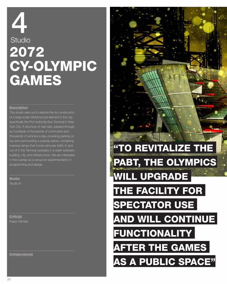
This studio sets out to explore the re-construction
of a large-scale infrastructural element in the city,
specifically the Port Authority Bus Terminal in New
York City. A structure of vast size, passed through
by hundreds of thousands of commuters and
thousands of vehicles a day, providing parking on
top and surmounting a subway below, containing
massive ramps that funnel vehicular traffic in and
out of it, the Terminal operates in a realm between
building, city, and infrastructure. We are interested
in this overlap as a venue for experimentation in
programming and design.
Studio IV
Kazys Varnelis
4Studio
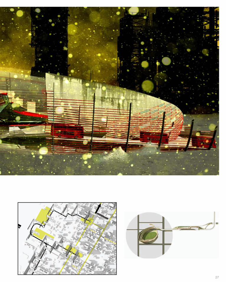
“TO REVITALIZE THE
PABT, THE OLYMPICS
WILL UPGRADE
THE FACILITY FOR
SPECTATOR USE
AND WILL CONTINUE
FUNCTIONALITY
AFTER THE GAMES
AS A PUBLIC SPACE”
27
Integrating the
Highline
ABus TerminalStadium
CB
291 yds
1275 yds
0 yds
159 yds
408 yds
672 yds1037 yds
1544 yds
937 yds
1275 yds
1761 yds
A C E
A C E
N Q RS W
1 2 3 7
1948 yds
1903 yds
2069 yds
2248 yds
1644 yds
1206 yds
1261 yds
671 yds
To Pier 40
To Manhattan Uptown
To New Jersey Sites
28
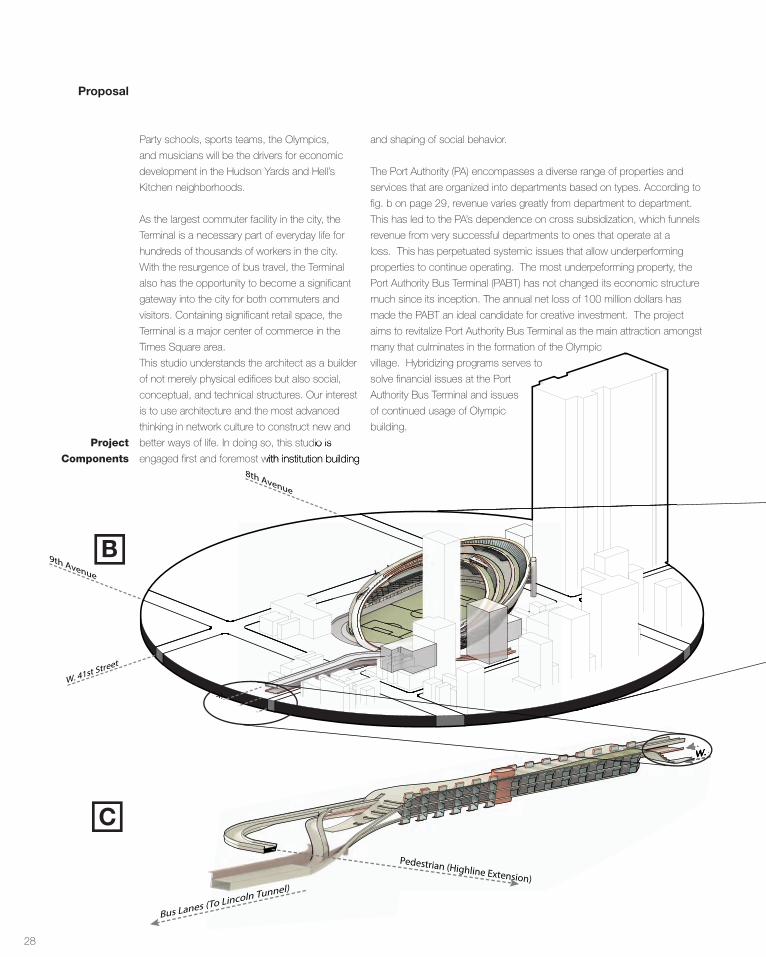
Proposal
Party schools, sports teams, the Olympics,
and musicians will be the drivers for economic
development in the Hudson Yards and Hell’s
Kitchen neighborhoods.
As the largest commuter facility in the city, the
Terminal is a necessary part of everyday life for
hundreds of thousands of workers in the city.
With the resurgence of bus travel, the Terminal
also has the opportunity to become a significant
gateway into the city for both commuters and
visitors. Containing significant retail space, the
Terminal is a major center of commerce in the
Times Square area.
This studio understands the architect as a builder
of not merely physical edifices but also social,
conceptual, and technical structures. Our interest
is to use architecture and the most advanced
thinking in network culture to construct new and
better ways of life. In doing so, this studio is
engaged first and foremost with institution building
better ways of life. In doing so, this studio is
engaged first and foremost with institution building
Pedestrian (Highline Extension)
Bus Lanes (To Lincoln Tunnel)
W. 40th Street
Pedestrian (Highline Extension)
Bus Lanes (To Lincoln Tunnel)
W. 41st Street
9th Avenue
8th Avenue
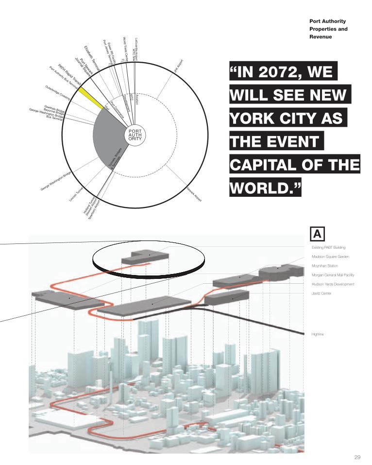
and shaping of social behavior.
The Port Authority (PA) encompasses a diverse range of properties and
services that are organized into departments based on types. According to
fig. b on page 29, revenue varies greatly from department to department.
This has led to the PA’s dependence on cross subsidization, which funnels
revenue from very successful departments to ones that operate at a
loss. This has perpetuated systemic issues that allow underperforming
properties to continue operating. The most underpeforming property, the
Port Authority Bus Terminal (PABT) has not changed its economic structure
much since its inception. The annual net loss of 100 million dollars has
made the PABT an ideal candidate for creative investment. The project
aims to revitalize Port Authority Bus Terminal as the main attraction amongst
many that culminates in the formation of the Olympic
village. Hybridizing programs serves to
solve financial issues at the Port
Authority Bus Terminal and issues
of continued usage of Olympic
building.
Pedestrian (Highline Extension)
Bus Lanes (To Lincoln Tunnel)
W. 40th StreetW. 40th St
Pedestrian (Highline Extension)
Bus Lanes (To Lincoln Tunnel)
W. 41st Street
9th Avenue
8th Avenue
Project
Components
C
B
29
AHighline Extention Nodes
1. Existing PABT Building2. Madison Square Garden3. Moynihan Station4. Morgan General Mail Facility5. Hudson Yards Development 6. Javitz Center
Existing PABT Building
Madison Square Garden
Moynihan Station
Morgan General Mail Facility
Hudson Yards Development
Javitz Center
Highline
4
Gross Operating Revenues
PORT AUTHORITY
Aviation
LaGuardia Airport
Tunn
els,
Brid
ges
& Te
rmin
als
Rail
Port Comm
erceD
evelopment
WTC
JFK
Airp
ort
Newark Airport
Tete
rbor
o Ai
rpor
t
Hol
land
Tun
nel
Linco
ln Tu
nnelGeorge W
ashington Bridge
Bayonne Bridge
Goethals Bridge
Outerbridge Crossing
Port Authority Bus Terminal
Port Newark
Elizabeth Terminal
Port Jersey Term
ina1 lE
ssex RR
Facility
World
Trade C
enter
2
WTC
Si te
Stew
art A
irpor
t
i
George Washington Br dge Bus Terminal
Journal Square
PATH Rapid Transit
Brooklyn TerminalRed Hook Container Terminal
Howland Hook TerminalGreenville Yard
New York & New Jersey Rail
Queens West WaterfrontHoboken Waterfront
Newark Legal & Comm CenterTeleport
Ferry Transportation ServicesBathgate Industrial Park
PA Industrial Park
{
{
2011 - PORT AUTHORITY
Sources:Port Authority Budget Report 2011 (December 7, 2010)
Port Authority
Properties and
Revenue
“IN 2072, WE
WILL SEE NEW
YORK CITY AS
THE EVENT
CAPITAL OF THE
WORLD.”
30
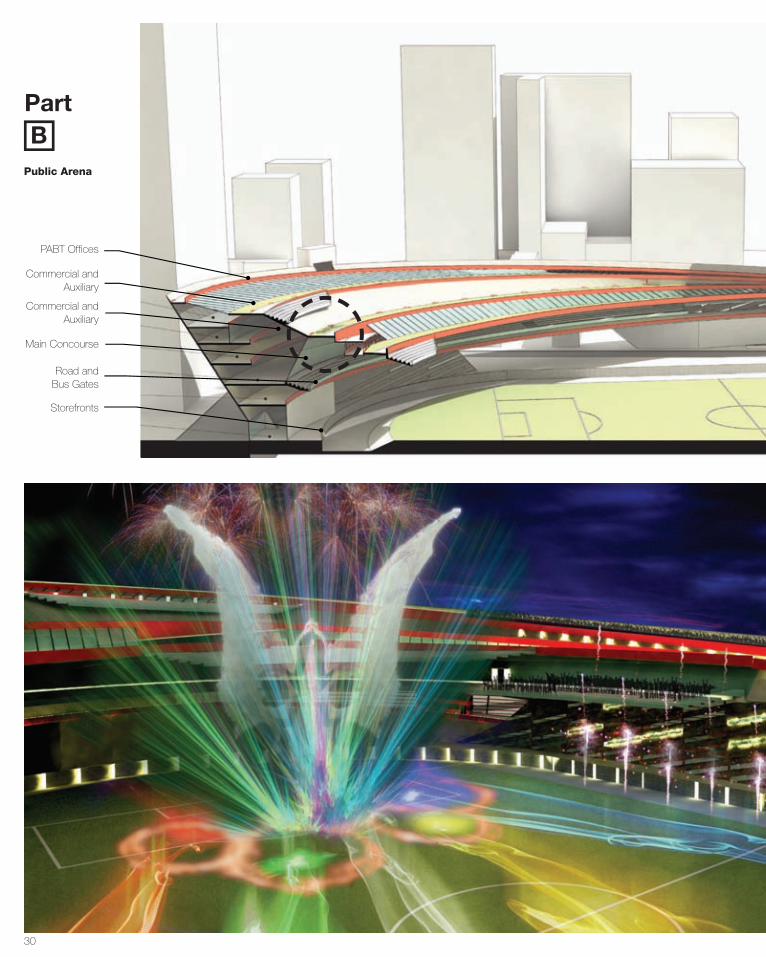
BPart
PABT Offices
Commercial and Auxiliary
Commercial and Auxiliary
Main Concourse
Road and Bus Gates
Storefronts
Public Arena
31
2072 Venues
Events
2012 Venues
Cer
emon
ies
Triathlon
Vill
age
Press
Ctr
Track
Cycl
ingBeac
h V-B
all
A rchery
A thletics
Basketball
Boxing
H andball
Free Wrestling
Greco-RomanBadminton
FencingShootingTable Tennis
Weightlifting
Artistic G
ym.
Rhythm
ic Gym
.
Trampoline
Tenn
is
BMX
Mou
ntain
Bik
e
Road
Cycl
ing
Indoor
V-B
allDressag
eE ventingJumping
Football
Judo
Taekwondo
Diving
Swimming
Synchronized
Water Polo
Sprint Kayak
Slalom KayakRowing
Sailing
Pentathlon
Field Hockey
West
Side
Sta
d.
Mai
n Pr
ess C
tr
Barclays
Javit
s
William
sburg
Brreezy Point
Mad
ison
Sq.
Cen
tral P
ark
Javits
Cent
er/Beac
hPA
BT
Pier
40
Mad
ison S
quare
Gard
enThe
High
line
Central Park
Baker’s A thletic Complex
Barcl
ay’s
Ctr
UST
A C
tr
Meadowlands
Izod Center
Meadowlands Racetrack
MetL ife Stadium
Weehawken Waterfront
E llis Island
L iberty State Park
FMCR Ctr.
USTA Ctr.
Water Polo C
tr.
Olympic Stad.
Yankee369th A rmoryPelham Bay Ctr.
Baker FieldQueensbridge
BMX Stadium
Greenbelt C
tr.
Fresh Kills P
ark
Fort Wadsworth
Richmond Ball.
N assau Col.
Izod Center
Giants Stad.
Gillette Stad.
Yale Bowl
L incoln Financial
FedE x Field
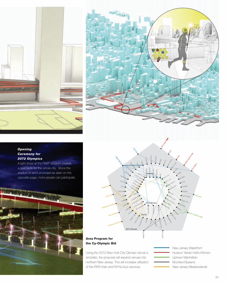
Area Program for
the Cy-Olympic Bid
Using the 2012 New York City Olympic bid as a
template, the proposal will expand venues into
northern New Jersey. This will increase utilization
of the PATH train and NY-NJ bus services.
New Jersey Waterfront
Hudson Yards/ Hell’s Kitchen
Uptown Manhattan
Brooklyn/Queens
New Jersey Meadowlands
/ Beaeae chchc
A light show at the PABT stadium creates
a spectacle for the whole city. Since the
stadium is semi-enclosed as seen on the
opposite page, more people can participate.
Opening
Ceremony for
2072 Olympics

32
Movement Digram
Pedestrian
Vehicular
Unoptimized
Queue
Memory Is
Important
Start and
End Strong
Be Fair Occupy Time
• Memories can be
digitally augmented
• Subconscious
augmentation
• The end can be
a shared digital
experience
• The start begins
online
• Memory set at the
end
• Economically
unstratified
• Free tickets
• demand increase/
longer lines
• Nodes of
Interaction
• Filled time seem
to pass more
quickly
• Moon illusion
• It’s not a line!
A 1 2 3 4
Design Rules for
Queues for the
Future
Donald Norman, an
academic in cognitive
science, design, and
usability engineering,
developed eight
principles to optimize
the experience of
waiting lines.
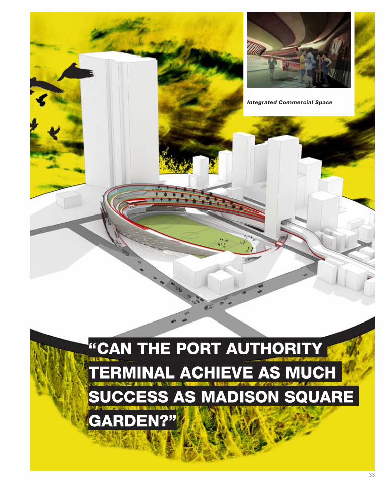
33
“CAN THE PORT AUTHORITY
TERMINAL ACHIEVE AS MUCH
SUCCESS AS MADISON SQUARE
GARDEN?”
Integrated Commercial Space
34
Part
C
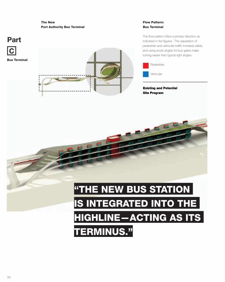
The New
Port Authority Bus Terminal
Flow Pattern:
Bus Terminal
Existing and Potential
Site Program
The flow pattern infers a primary direction as
indicated in the figures. The separation of
pedestrian and vehicular traffic increase safety
and using acute angles for bus gates make
turning easier than typical right angles.
Pedestrian
Vehicular
Bus Terminal
Existing and Potential
Site Program
“THE NEW BUS STATION
IS INTEGRATED INTO THE
HIGHLINE—ACTING AS ITS
TERMINUS.”
35
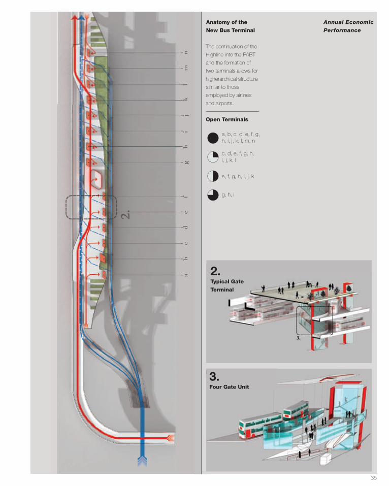
Annual Economic
Performance
Anatomy of the
New Bus Terminal
The continuation of the
Highline into the PABT
and the formation of
two terminals allows for
higherarchical structure
similar to those
employed by airlines
and airports.
Open Terminals
a, b, c, d, e, f, g, h, i, j, k, l, m, n
c, d, e, f, g, h, i, j, k, l
e, f, g, h, i, j, k
g, h, i
2. Typical Gate
Terminal
3. Four Gate Unit
36
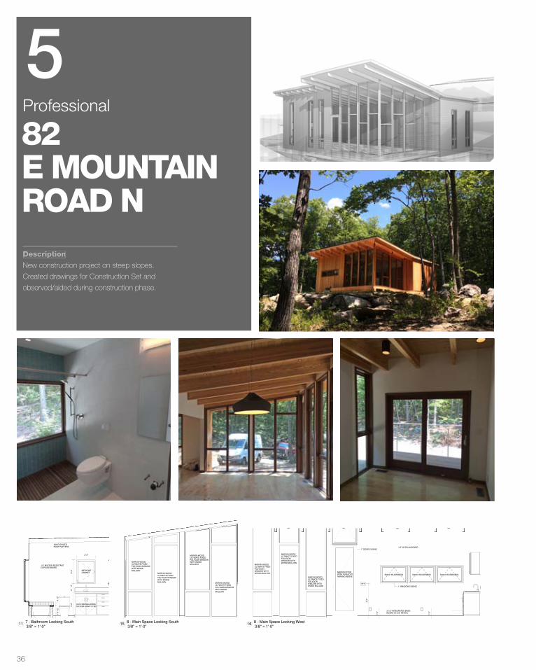
Description
New construction project on steep slopes.
Created drawings for Construction Set and
observed/aided during construction phase.
82E MOUNTAINROAD N
5Professional
GUEST HOUSE PERSPECTIVES PAGE A1300
1GUEST HOUSE WEST
1'-0
"
1'-0
"
1/2" GYPSUM BOARD
1" WINDOW CASING
Marvin WUAWN3624 Marvin WUAWN3624 Marvin WUAWN3624
3 1/2" INTEGRATED BASE-
BOARD W/ 3/8" REVEAL
1'-0
"
1/2" GYPSUM BOARD
3 1/2" INTEGRATED BASE-
BOARD W/ 3/8" REVEAL
MARVIN
ULTIMATE
PUSH OUT
CASEMENT
OVER FIXED
CASEMENT
BELOW
1'-0
"
4'-0
"
1/2" GYPSUM BOARD
2X8 EXPOSED
ROOF RAFTERS
3 1/2" INTEGRATED BASE-
BOARD W/ 3/8" REVEAL
1" DOOR CASING
4'-0
"
1/2" GYPSUM BOARD
1" DOOR CASING
1'-0
"3 1/2" INTEGRATED BASE-
BOARD W/ 3/8" REVEAL
1/2" GYPSUM BOARD
MARVIN
ULTIMATE
PUSH OUT
CASEMENT
OVER FIXED
CASEMENT
BELOW
2X8 EXPOSED
ROOF RAFTERS
1'-0
"
4'-0
"
2X8 EXPOSED
ROOF RAFTERS
1" DOOR CASING
1/2" GYPSUM BOARD
3 1/2" INTEGRATED BASE-
BOARD W/ 3/8" REVEAL
1'-0
"
1'-0
"
1/2" GYPSUM BOARD
3 1/2" INTEGRATED BASE-
BOARD W/ 3/8" REVEAL
OVERHEAD LIGHT
SWITCH
4'-0
"
1/2" GYPSUM BOARD
1" DOOR CASING
1/2" MILDEW RESISTANT
GYPSUM BOARD
TILE SURROUND TBD
3 1/2" INTEGRATED BASE-
BOARD W/ 3/8" REVEAL
1/2" MILDEW RESISTANT
GYPSUM BOARD
CUSTOM MILLWORK
OR IKEA VANITY TBD
2X8 EXPOSED
ROOF RAFTERS
MEDICINE
CABINET2'-9
"6
"6
"3
'-0
"
2'-2"
4 1
/2"
1'-5
1/2
"
MARVIN WOOD PICTURE
POLYGON - 60"X60"
1/2" MILDEW RESISTANT
GYPSUM BOARD
TILE SURROUND TBD
TILE
TBD
4'-0
"
1" DOOR CASING
FLAT PANEL
WOOD STAINED
DOOR
1/2" MILDEW RESISTANT
GYPSUM BOARD
1'-0
"
1'-0
"
1'-0
"
1" DOOR CASING
1/2" GYPSUM BOARD
1/2" GYPSUM BOARD
3 1/2" INTEGRATED BASE-
BOARD W/ 3/8" REVEAL
FLAT PANEL
WOOD STAINED
DOOR
WOOD PANEL
CEILING
5 3
/4"
5 3
/4"
5 3
/4"
DISHWASHER
TBD
RANGE/OVEN
TBD
SLOPED
HOOD
VENT
REFRIGERATOR
TBD
CUSTOM MILLWORK
OR IKEA KITCHEN
TBD
TILE BACKSPLASH
2X8 EXPOSED
ROOF RAFTERS
MARVIN WOOD
ULTIMATE FIXED
POLYGON WINDOW
WITH WOOD
MULLION
MARVIN WOOD
ULTIMATE FIXED
POLYGON WINDOW
WITH WOOD
MULLION
MARVIN WOOD
ULTIMATE FIXED
POLYGON WINDOW
WITH WOOD
MULLION
MARVIN WOOD
ULTIMATE FIXED
POLYGON WINDOW
WITH WOOD
MULLION
1'-0
"
1'-0
"
4'-0
"
Marvin WUAWN3624 Marvin WUAWN3624 Marvin WUAWN3624
MARVIN WOOD
ULTIMATE FIXED
POLYGON
WINDOW WITH
WOOD MULLION
MARVIN WOOD
ULTIMATE FIXED
POLYGON
WINDOW WITH
WOOD MULLION
MARVIN WOOD
ULTIMATE FIXED
POLYGON
WINDOW WITH
WOOD MULLION
1/2" GYPSUM BOARD
1" WINDOW CASING
3 1/2" INTEGRATED BASE-
BOARD W/ 3/8" REVEAL
1" DOOR CASING
MARVIN DOOR
WITH PUSH OUT
AWNING ABOVE
DRAWING ISSUE
DRAWING DESCRIPTION
ISSUE
DATEISSUE NO.
01
02
03
PERMIT SET
Revision Schedule
REVISION
NO. REVISION DESCRIPTION
REVISION
DATE
3/8" = 1'-0"2
5 - Bedroom 1 Looking East
3/8" = 1'-0"3
5 - Bedroom 1 Looking South
3/8" = 1'-0"1
5 - Bedroom 1 Looking North
3/8" = 1'-0"4
5 - Bedroom 1 Looking West
3/8" = 1'-0"5
6 - Bedroom 2 Looking North
3/8" = 1'-0"7
6 - Bedroom 2 Looking South
3/8" = 1'-0"6
6 - Bedroom 2 Looking East
3/8" = 1'-0"8
6 - Bedroom 2 Looking West
3/8" = 1'-0"9
7 - Bathroom Looking North
3/8" = 1'-0"11
7 - Bathroom Looking South
3/8" = 1'-0"10
7 - Bathroom Looking East
3/8" = 1'-0"12
7 - Bathroom Looking West
3/8" = 1'-0"14
8 - Main Space Looking East
3/8" = 1'-0"13
8 - Main Space Looking North
3/8" = 1'-0"15
8 - Main Space Looking South
3/8" = 1'-0"16
8 - Main Space Looking West
1'-0
"
1'-0
"
1/2" GYPSUM BOARD
1" WINDOW CASING
Marvin WUAWN3624 Marvin WUAWN3624 Marvin WUAWN3624
3 1/2" INTEGRATED BASE-
BOARD W/ 3/8" REVEAL
1'-0
"
1/2" GYPSUM BOARD
3 1/2" INTEGRATED BASE-
BOARD W/ 3/8" REVEAL
MARVIN
ULTIMATE
PUSH OUT
CASEMENT
OVER FIXED
CASEMENT
BELOW
1'-0
"
4'-0
"
1/2" GYPSUM BOARD
2X8 EXPOSED
ROOF RAFTERS
3 1/2" INTEGRATED BASE-
BOARD W/ 3/8" REVEAL
1" DOOR CASING
4'-0
"
1/2" GYPSUM BOARD
1" DOOR CASING
1'-0
"3 1/2" INTEGRATED BASE-
BOARD W/ 3/8" REVEAL
1/2" GYPSUM BOARD
MARVIN
ULTIMATE
PUSH OUT
CASEMENT
OVER FIXED
CASEMENT
BELOW
2X8 EXPOSED
ROOF RAFTERS
1'-0
"
4'-0
"
2X8 EXPOSED
ROOF RAFTERS
1" DOOR CASING
1/2" GYPSUM BOARD
3 1/2" INTEGRATED BASE-
BOARD W/ 3/8" REVEAL
1'-0
"
1'-0
"
1/2" GYPSUM BOARD
3 1/2" INTEGRATED BASE-
BOARD W/ 3/8" REVEAL
OVERHEAD LIGHT
SWITCH
4'-0
"1/2" GYPSUM BOARD
1" DOOR CASING
1/2" MILDEW RESISTANT
GYPSUM BOARD
TILE SURROUND TBD
3 1/2" INTEGRATED BASE-
BOARD W/ 3/8" REVEAL
1/2" MILDEW RESISTANT
GYPSUM BOARD
CUSTOM MILLWORK
OR IKEA VANITY TBD
2X8 EXPOSED
ROOF RAFTERS
MEDICINE
CABINET2'-9
"6
"6
"3
'-0
"
2'-2"
4 1
/2"
1'-5
1/2
"
MARVIN WOOD PICTURE
POLYGON - 60"X60"
1/2" MILDEW RESISTANT
GYPSUM BOARD
TILE SURROUND TBD
TILE
TBD
4'-0
"
1" DOOR CASING
FLAT PANEL
WOOD STAINED
DOOR
1/2" MILDEW RESISTANT
GYPSUM BOARD
1'-0
"
1'-0
"
1'-0
"
1" DOOR CASING
1/2" GYPSUM BOARD
1/2" GYPSUM BOARD
3 1/2" INTEGRATED BASE-
BOARD W/ 3/8" REVEAL
FLAT PANEL
WOOD STAINED
DOOR
WOOD PANEL
CEILING
5 3
/4"
5 3
/4"
5 3
/4"
DISHWASHER
TBD
RANGE/OVEN
TBD
SLOPED
HOOD
VENT
REFRIGERATOR
TBD
CUSTOM MILLWORK
OR IKEA KITCHEN
TBD
TILE BACKSPLASH
2X8 EXPOSED
ROOF RAFTERS
MARVIN WOOD
ULTIMATE FIXED
POLYGON WINDOW
WITH WOOD
MULLION
MARVIN WOOD
ULTIMATE FIXED
POLYGON WINDOW
WITH WOOD
MULLION
MARVIN WOOD
ULTIMATE FIXED
POLYGON WINDOW
WITH WOOD
MULLION
MARVIN WOOD
ULTIMATE FIXED
POLYGON WINDOW
WITH WOOD
MULLION
1'-0
"
1'-0
"
4'-0
"
Marvin WUAWN3624 Marvin WUAWN3624 Marvin WUAWN3624
MARVIN WOOD
ULTIMATE FIXED
POLYGON
WINDOW WITH
WOOD MULLION
MARVIN WOOD
ULTIMATE FIXED
POLYGON
WINDOW WITH
WOOD MULLION
MARVIN WOOD
ULTIMATE FIXED
POLYGON
WINDOW WITH
WOOD MULLION
1/2" GYPSUM BOARD
1" WINDOW CASING
3 1/2" INTEGRATED BASE-
BOARD W/ 3/8" REVEAL
1" DOOR CASING
MARVIN DOOR
WITH PUSH OUT
AWNING ABOVE
DRAWING ISSUE
DRAWING DESCRIPTION
ISSUE
DATEISSUE NO.
01
02
03
PERMIT SET
Revision Schedule
REVISION
NO. REVISION DESCRIPTION
REVISION
DATE
3/8" = 1'-0"2
5 - Bedroom 1 Looking East
3/8" = 1'-0"3
5 - Bedroom 1 Looking South
3/8" = 1'-0"1
5 - Bedroom 1 Looking North
3/8" = 1'-0"4
5 - Bedroom 1 Looking West
3/8" = 1'-0"5
6 - Bedroom 2 Looking North
3/8" = 1'-0"7
6 - Bedroom 2 Looking South
3/8" = 1'-0"6
6 - Bedroom 2 Looking East
3/8" = 1'-0"8
6 - Bedroom 2 Looking West
3/8" = 1'-0"9
7 - Bathroom Looking North
3/8" = 1'-0"11
7 - Bathroom Looking South
3/8" = 1'-0"10
7 - Bathroom Looking East
3/8" = 1'-0"12
7 - Bathroom Looking West
3/8" = 1'-0"14
8 - Main Space Looking East
3/8" = 1'-0"13
8 - Main Space Looking North
3/8" = 1'-0"15
8 - Main Space Looking South
3/8" = 1'-0"16
8 - Main Space Looking West
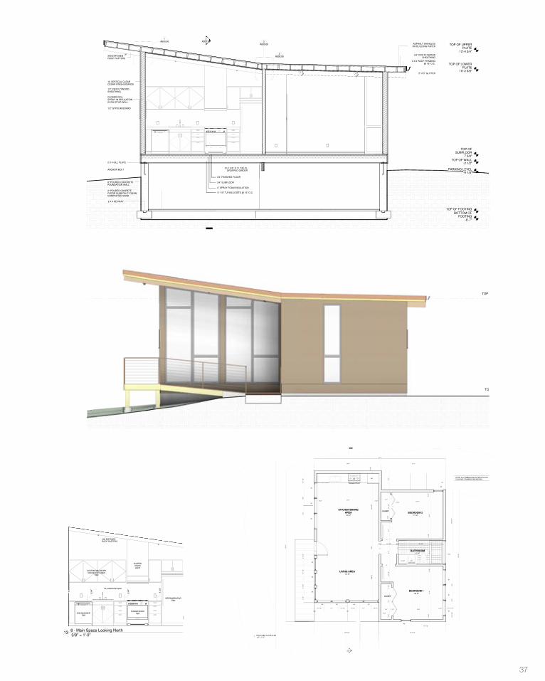
37
TOP OF
SUBFLOOR
7 3/8"
TOP OF LOWER
PLATE
10'-2 3/8"
TOP OF UPPER
PLATE
12'-4 3/4"
2
A300.00
TOP OF WALL
-2 1/2"
TOP OF FOOTING
-5'-9"BOTTOM OF
FOOTING
-6'-7"
2 X 4 KEYWAY
8" POURED CONCRETE
FOUNDATION WALL
2" POURED CONRETE
FLOOR SLAB ON 6" CLEAN
COMPACTED SAND
ANCHOR BOLT
2 X 4 SILL PLATE
CLOSED CELL
SPRAY-IN INSULATION
IN 2X6 STUD WALL
1/2" GYPSUM BOARD
1/2" CDX PLYWOOD
SHEATHING
1X VERTICAL CLEAR
CEDAR FINISH BOARDS
4” SPRAY FOAM INSULATION
11-7/8” TJI-560 JOISTS @ 16” O.C.
3/4” FINISHED FLOOR
3/4” SUBFLOOR
(3) 1 3/4" X 11 7/8 LVL
DROPPED GIRDER
2 X 6 ROOF FRAMING
@ 16” O.C.
3/4” CDX PLYWOOD
SHEATHING
ASPHALT SHINGLES
ON BUILDING PAPER
5" X 5" GUTTER
3X8 EXPOSED
ROOF RAFTERS
PARKING LEVEL
-9 1/8"
A600.00
1
A600.00
2
A600.00
3
TOP OF
SUBFLOOR
7 3/8"
TOP OF LOWER
PLATE
10'-2 3/8"
TOP OF UPPER
PLATE
12'-4 3/4"
TOP OF WALL
-2 1/2"
TOP OF FOOTING
-5'-9"
BOTTOM OF
FOOTING
-6'-7"
2 X 4 KEYWAY
8" POURED CONCRETE
FOUNDATION WALL
2" POURED CONRETE
FLOOR SLAB ON 6" CLEAN
COMPACTED SAND
ANCHOR BOLT
2 X 4 SILL PLATE
CLOSED CELL
SPRAY-IN INSULATION
IN 2X6 STUD WALL
1/2" GYPSUM BOARD
1/2" CDX PLYWOOD
SHEATHING
VERTICAL CLEAR
CEDAR FINISH BOARDS
(3) 1 3/4" X 11 7/8 LVL DROPPED GIRDER
32” X 18”
CRAWLSPACE
ACCESS 4” SPRAY FOAM INSULATION
4" LALLY COLUMN ON
2'-6" X 2'-6" X 12" FOOTING
9-1/2” TJI-230 JOISTS @ 16” O.C.
2 X 6 ROOF FRAMING
@ 16” O.C.
3/4” CDX PLYWOOD
SHEATHING
ASPHALT SHINGLES ON
BUILDING PAPER
3/4” FINISHED FLOOR
3/4” SUBFLOOR
1 X 6 FASCIA
PARKING LEVEL
-9 1/8"
2x8 STRUCTURAL JOISTS
FOR ACCESSABILITY RAMP
3X8 EXPOSED ROOF
RAFTERS
A600.00
4
DRAWING ISSUE
DRAWING DESCRIPTION
ISSUE
DATEISSUE NO.
01
02
03
PERMIT SET
Revision Schedule
REVISION
NO. REVISION DESCRIPTION
REVISION
DATE
1/2" = 1'-0"1
SECTION 1
1/2" = 1'-0"2
SECTION 2
TOP OF
SUBFLOOR
7 3/8"
TOP OF LOWER
PLATE
10'-2 3/8"
TOP OF UPPER
PLATE
12'-4 3/4"
TOP OF WALL
-2 1/2"
TOP OF FOOTING
-5'-9"BOTTOM OF
FOOTING
-6'-7"
PARKING LEVEL
-9 1/8"
TOP OF
SUBFLOOR
7 3/8"
TOP OF LOWER
PLATE
10'-2 3/8"
TOP OF WALL
-2 1/2"
TOP OF FOOTING
-5'-9"BOTTOM OF
FOOTING
-6'-7" 1/2" = 1'-0"
22 - Northwest Elevation
1/2" = 1'-0"1
4 - Southwest Elevation
DRAWING ISSUE
DRAWING DESCRIPTION
ISSUE
DATEISSUE NO.
01
02
03
PERMIT SET
Revision Schedule
REVISION
NO. REVISION DESCRIPTION
REVISION
DATE
DN DNDN
REF.
2
A300.00
115 SF
BEDROOM 2
47 SF
BATHROOM
CLOSET
4'-0
"
188 SF
KITCHEN/DINING
AREA
164 SF
LIVING AREA
6'-0
1/2
"
CLOSET
128 SF
BEDROOM 1
8'-4 1/2"
2'-1
0 1
/4"
3 1
/2"
31
'-11
"
2'-1"
3 1/2"
3'-7
"5
'-1
"3
'-5
1/2
"3
1/2
"7
'-7
"5
1/2
"
5 1/2"10'-8"3 1/2"2'-4"
5 1
/2"
9'-11
"3
1/2
"5
'-1
"3
1/2
"1
1'-4
"5
1/2
"
14'-2"
13
'-2
1/2
"
27
'-10
"
10'-11"
9'-6 1/2"3 1/2"3'-5 1/2"3 1/2"
3 1/2"13'-3"
5 1/2"
13'-7"
27'-9"
3 1/2"
14'-0 1/2"
1'-6"
3'-3
"3
'-3
"
2
6
3
1
5
4
N8
N10
N1
N1
N1
N8
N7N6N5N4
N2
N3
N2
N1
N1
N1
4'-1
1/4
"3
'-3
"3
'-3
"1
'-10
"3
'-1
1/2
"3
'-1
1/2
"3
'-4
1/2
"
2'-2 1/8" 3'-1" 1'-6 1/2" 1'-6 1/2" 3'-1" 1'-9 1/4"
9'-8
1/2
"2
'-9
"1
4'-4
1/2
"
5 1
/2"
13'-8 1/2"
1'-9 1/2"
interior width
2'-0"
7
DRAWING ISSUE
DRAWING DESCRIPTION
ISSUE
DATEISSUE NO.
01
02
03
PERMIT SET
ACCESSORY STRUCTURE: GUEST HOUSE
NO. OF FLOORS: 1
FOOTPRINT:787 SQFT
N
Revision Schedule
REVISION
NO. REVISION DESCRIPTION
REVISION
DATE
BID SET 02/24/14
1/2" = 1'-0"1
PROPOSED FLOOR PLAN
NOTE: ALL DIMENSIONS IN FIRST FLOOR
PLAN ARE FRAMING DIMENSIONS
1'-0
"
1'-0
"
1/2" GYPSUM BOARD
1" WINDOW CASING
Marvin WUAWN3624 Marvin WUAWN3624 Marvin WUAWN3624
3 1/2" INTEGRATED BASE-
BOARD W/ 3/8" REVEAL
1'-0
"
1/2" GYPSUM BOARD
3 1/2" INTEGRATED BASE-
BOARD W/ 3/8" REVEAL
MARVIN
ULTIMATE
PUSH OUT
CASEMENT
OVER FIXED
CASEMENT
BELOW
1'-0
"
4'-0
"
1/2" GYPSUM BOARD
2X8 EXPOSED
ROOF RAFTERS
3 1/2" INTEGRATED BASE-
BOARD W/ 3/8" REVEAL
1" DOOR CASING
4'-0
"
1/2" GYPSUM BOARD
1" DOOR CASING
1'-0
"3 1/2" INTEGRATED BASE-
BOARD W/ 3/8" REVEAL
1/2" GYPSUM BOARD
MARVIN
ULTIMATE
PUSH OUT
CASEMENT
OVER FIXED
CASEMENT
BELOW
2X8 EXPOSED
ROOF RAFTERS
1'-0
"
4'-0
"
2X8 EXPOSED
ROOF RAFTERS
1" DOOR CASING
1/2" GYPSUM BOARD
3 1/2" INTEGRATED BASE-
BOARD W/ 3/8" REVEAL
1'-0
"
1'-0
"
1/2" GYPSUM BOARD
3 1/2" INTEGRATED BASE-
BOARD W/ 3/8" REVEAL
OVERHEAD LIGHT
SWITCH
4'-0
"
1/2" GYPSUM BOARD
1" DOOR CASING
1/2" MILDEW RESISTANT
GYPSUM BOARD
TILE SURROUND TBD
3 1/2" INTEGRATED BASE-
BOARD W/ 3/8" REVEAL
1/2" MILDEW RESISTANT
GYPSUM BOARD
CUSTOM MILLWORK
OR IKEA VANITY TBD
2X8 EXPOSED
ROOF RAFTERS
MEDICINE
CABINET2'-9
"6
"6
"3
'-0
"
2'-2"
4 1
/2"
1'-5
1/2
"
MARVIN WOOD PICTURE
POLYGON - 60"X60"
1/2" MILDEW RESISTANT
GYPSUM BOARD
TILE SURROUND TBD
TILE
TBD
4'-0
"
1" DOOR CASING
FLAT PANEL
WOOD STAINED
DOOR
1/2" MILDEW RESISTANT
GYPSUM BOARD
1'-0
"
1'-0
"
1'-0
"
1" DOOR CASING
1/2" GYPSUM BOARD
1/2" GYPSUM BOARD
3 1/2" INTEGRATED BASE-
BOARD W/ 3/8" REVEAL
FLAT PANEL
WOOD STAINED
DOOR
WOOD PANEL
CEILING
5 3
/4"
5 3
/4"
5 3
/4"
DISHWASHER
TBD
RANGE/OVEN
TBD
SLOPED
HOOD
VENT
REFRIGERATOR
TBD
CUSTOM MILLWORK
OR IKEA KITCHEN
TBD
TILE BACKSPLASH
2X8 EXPOSED
ROOF RAFTERS
MARVIN WOOD
ULTIMATE FIXED
POLYGON WINDOW
WITH WOOD
MULLION
MARVIN WOOD
ULTIMATE FIXED
POLYGON WINDOW
WITH WOOD
MULLION
MARVIN WOOD
ULTIMATE FIXED
POLYGON WINDOW
WITH WOOD
MULLION
MARVIN WOOD
ULTIMATE FIXED
POLYGON WINDOW
WITH WOOD
MULLION
1'-0
"
1'-0
"
4'-0
"
Marvin WUAWN3624 Marvin WUAWN3624 Marvin WUAWN3624
MARVIN WOOD
ULTIMATE FIXED
POLYGON
WINDOW WITH
WOOD MULLION
MARVIN WOOD
ULTIMATE FIXED
POLYGON
WINDOW WITH
WOOD MULLION
MARVIN WOOD
ULTIMATE FIXED
POLYGON
WINDOW WITH
WOOD MULLION
1/2" GYPSUM BOARD
1" WINDOW CASING
3 1/2" INTEGRATED BASE-
BOARD W/ 3/8" REVEAL
1" DOOR CASING
MARVIN DOOR
WITH PUSH OUT
AWNING ABOVE
DRAWING ISSUE
DRAWING DESCRIPTION
ISSUE
DATEISSUE NO.
01
02
03
PERMIT SET
Revision Schedule
REVISION
NO. REVISION DESCRIPTION
REVISION
DATE
3/8" = 1'-0"2
5 - Bedroom 1 Looking East
3/8" = 1'-0"3
5 - Bedroom 1 Looking South
3/8" = 1'-0"1
5 - Bedroom 1 Looking North
3/8" = 1'-0"4
5 - Bedroom 1 Looking West
3/8" = 1'-0"5
6 - Bedroom 2 Looking North
3/8" = 1'-0"7
6 - Bedroom 2 Looking South
3/8" = 1'-0"6
6 - Bedroom 2 Looking East
3/8" = 1'-0"8
6 - Bedroom 2 Looking West
3/8" = 1'-0"9
7 - Bathroom Looking North
3/8" = 1'-0"11
7 - Bathroom Looking South
3/8" = 1'-0"10
7 - Bathroom Looking East
3/8" = 1'-0"12
7 - Bathroom Looking West
3/8" = 1'-0"14
8 - Main Space Looking East
3/8" = 1'-0"13
8 - Main Space Looking North
3/8" = 1'-0"15
8 - Main Space Looking South
3/8" = 1'-0"16
8 - Main Space Looking West
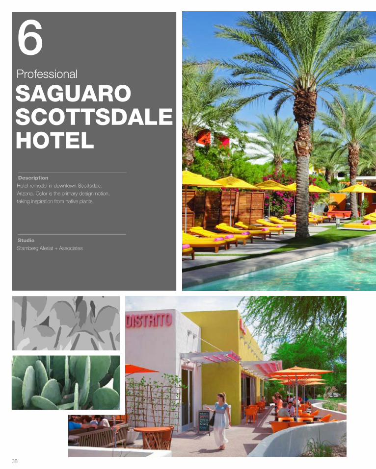
38
Description
Studio
Hotel remodel in downtown Scottsdale,
Arizona. Color is the primary design notion,
taking inspiration from native plants.
Stamberg Aferiat + Associates
SAGUAROSCOTTSDALEHOTEL
6Professional
INSPIRATION:PRICKLY PEAR CACTUS
ABSTRACTION:SHADES OF LIGHT
DETAIL:VARYING SIZE PERFORATIONS
A
CONSTRUCTION: A PERFORATED, CORRUGATED SCREEN WALL 8Ó FROM EXISTING WALL
APPLICATION: NEW RESTAURANT FA‚ ADE
8Ó
CURRENT FA‚ ADE:
INSPIRATION:PRICKLY PEAR CACTUS
ABSTRACTION:SHADES OF LIGHT
DETAIL:VARYING SIZE PERFORATIONS
A
CONSTRUCTION: A PERFORATED, CORRUGATED SCREEN WALL 8Ó FROM EXISTING WALL
APPLICATION: NEW RESTAURANT FA‚ ADE
8Ó
CURRENT FA‚ ADE:
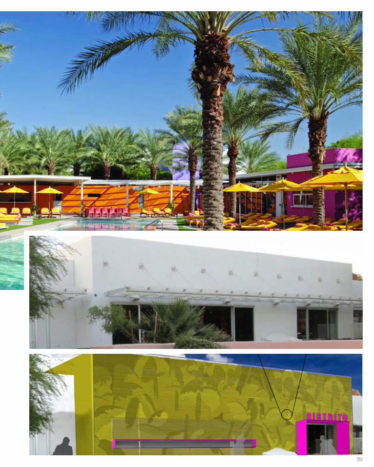
39
INSPIRATION:PRICKLY PEAR CACTUS
ABSTRACTION:SHADES OF LIGHT
DETAIL:VARYING SIZE PERFORATIONS
A
CONSTRUCTION: A PERFORATED, CORRUGATED SCREEN WALL 8Ó FROM EXISTING WALL
APPLICATION: NEW RESTAURANT FA‚ ADE
8Ó
CURRENT FA‚ ADE:
INSPIRATION:PRICKLY PEAR CACTUS
ABSTRACTION:SHADES OF LIGHT
DETAIL:VARYING SIZE PERFORATIONS
A
CONSTRUCTION: A PERFORATED, CORRUGATED SCREEN WALL 8Ó FROM EXISTING WALL
APPLICATION: NEW RESTAURANT FA‚ ADE
8Ó
CURRENT FA‚ ADE:
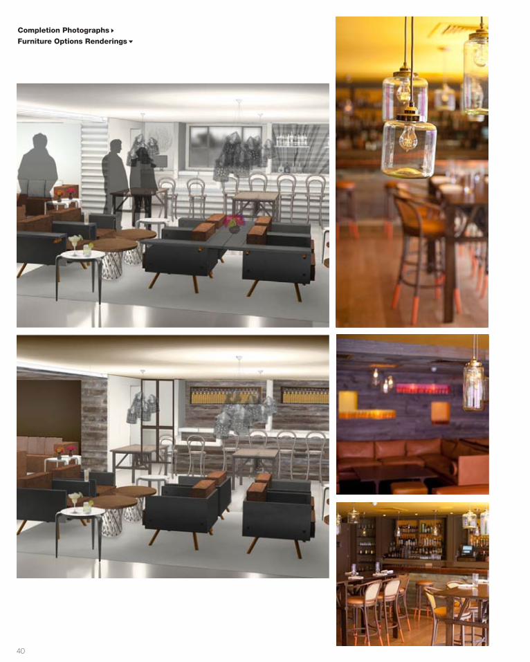
40
Completion Photographs
Furniture Options Renderings
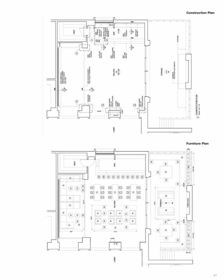
41
Construction Plan
Furniture Plan
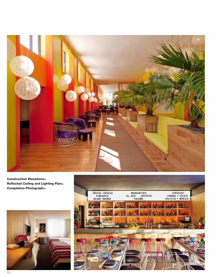
42
Construction Elevations
Reflected Ceiling and Lighting Plan
Completion Photograph
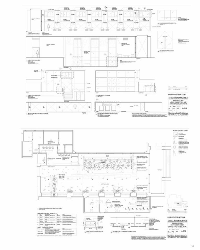
43

44
Description
Renovation project in Amagansett, NY
encompassing ADA accessibility, landscape,
and new interior finishes.
349CRANBERRYHOLE RD
7Professional
10' - 2 7/16"8'
- 0
3/16
"
10' - 1 5/16"
6' -
0"2'
- 9"
4' - 10 1/2"
8' -
0" 1/4" = 1'-0"1 Section 1
1/4" = 1'-0"3 Section 3 1/4" = 1'-0"4 Section 4
1/4" = 1'-0"2 Section 2
1/2" = 1'-0"5 Level 1 Copy 1
6 {3D} Copy 1
7 {3D} Copy 2
10' - 2 7/16"
8' -
0 3/
16"
10' - 1 5/16"
6' -
0"2'
- 9"
4' - 10 1/2"
8' -
0"
1/4" = 1'-0"1 Section 1
1/4" = 1'-0"3 Section 3 1/4" = 1'-0"4 Section 4
1/4" = 1'-0"2 Section 2
1/2" = 1'-0"5 Level 1 Copy 1
6 {3D} Copy 1
7 {3D} Copy 2
10' - 2 7/16"
8' -
0 3/
16"
10' - 1 5/16"6'
- 0"
2' -
9"
4' - 10 1/2"
8' -
0"
1/4" = 1'-0"1 Section 1
1/4" = 1'-0"3 Section 3 1/4" = 1'-0"4 Section 4
1/4" = 1'-0"2 Section 2
1/2" = 1'-0"5 Level 1 Copy 1
6 {3D} Copy 1
7 {3D} Copy 2
10' - 2 7/16"
8' -
0 3/
16"
10' - 1 5/16"
6' -
0"2'
- 9"
4' - 10 1/2"
8' -
0"
1/4" = 1'-0"1 Section 1
1/4" = 1'-0"3 Section 3 1/4" = 1'-0"4 Section 4
1/4" = 1'-0"2 Section 2
1/2" = 1'-0"5 Level 1 Copy 1
6 {3D} Copy 1
7 {3D} Copy 2
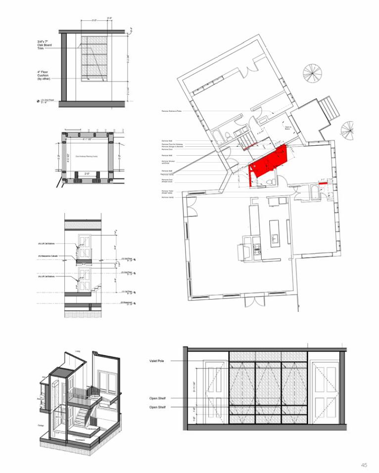
45
Remove Doorand Wall(Retain Door)
Down
Up
Remove Wall
4'-8"
3'-4"
Remove Doorand Wall(Retain Door)
Remove Wall
4'-4"
3'-0 1/8"
RemoveDoor and Wall(Retain Door)
Remove Door(Retain Door)
Remove Stringer & Banister
3'-3"
Remove Wine Rack
Remove Toilet(Retail Toilet)
Open toBelow
Down Down
Remove Door
Remove Wall
Remove Door(Retain Door)
Remove Showerand Drain
0'-11 1/4"
Remove Wall
Remove Vanity
Remove Wall
Remove Floor for Hoistway
6'-71/2"
Remove Stringer & Banister
Remove Vanity
Remove Shelves & Poles
4'-51/2"
3'-0 1/2"
5'-6 7/8"
2'-7" 1'-7 1/4"
AMAGANSETT, NEW YORK349 CRANBERRY HOLE ROAD
DRAWN BY:
DWG NO.:
SCALE:
DRAWING TITLE:
PROJECT NO.:
DATE:
PROJECT:
1/4" = 1'-0"
Demo Plan
11/14/13
AS
A1.01.00 1/4" = 1'-0"1 Plan - Basement/1st Floor Demolition 1/4" = 1'-0"2 Plan - 2nd/3rd Floor Demolition NN
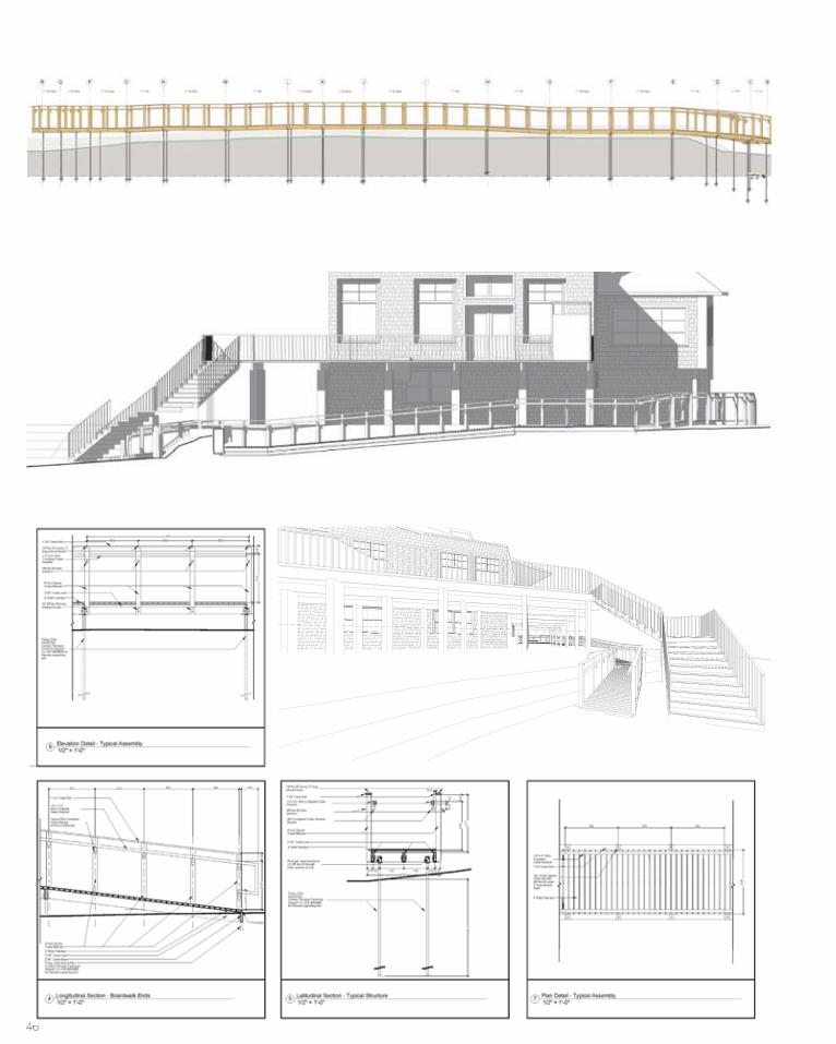
46
4L1.03
2'-0
"
2"x8" Cedar Joists
SCE, PLLC
AMAGANSETT, NEW YORK349 CRANBERRY HOLE ROAD
Fractal Group LLC
DRAWN BY:
DWG NO.:
SCALE:
DRAWING TITLE:
SEAL & SIGNATURE:
PROJECT NO.:
DATE:
PROJECT:
112 Connecticut Ave., Massapequa, NY 11758
T 516 446 0101
Structural Engineer:
CADO FILE No.
Design Architect:
23 East 7th Street Ground Floor, NewYork, NY 10003T 212 228 5617 F 212 228 5618
© 2014 FRACTAL GROUP LLC, ALL RIGHTS RESERVED
THIS DRAWING AND ALL GRAPHIC AND WRITTEN MATERIAL CONTAINED HEREIN,CONSTITUTES THE ORIGINAL AND UNPUBLISHED WORK OF FRACTAL
CONSTRUCTION LLC AND MAY NOT BE COPIED, DISTRIBUTED OR USED INWHOLE OR IN PART. WITHOUT EXPRESSED WRITTEN PERMISSION FROM FRACTAL
CONSTRUCTION LLC.
Notes/Legends:
As indicated
ADA Walkway Details
06/12/15
AC
L1.03
Project Status
Revision Schedule
RevisionNumber Revision Description
RevisionDate
1/4" = 1'-0"1 Section 33
1/4" = 1'-0"3 Section 35
1/4" = 1'-0"2 Section 42
1" = 1'-0"4 Section 46
1"x4" Cedar Rail
1.5" x 1.5" ADA Compliant Cedar Handrail
ADA Compliant Cedar Handrail Bracket
4"nom Square Cedar Baluster
4" Wide Teak/IPE
Concrete footings
6" Square posts
2"x8" Cedar Beam
Post galv. steel bracket w/ (2) 3/8" dia. SS throughbolts, washers & nuts
SCE, PLLC
AMAGANSETT, NEW YORK349 CRANBERRY HOLE ROAD
Fractal Group LLC
DRAWN BY:
DWG NO.:
SCALE:
DRAWING TITLE:
SEAL & SIGNATURE:
PROJECT NO.:
DATE:
PROJECT:
112 Connecticut Ave., Massapequa, NY 11758
T 516 446 0101
Structural Engineer:
CADO FILE No.
Design Architect:
23 East 7th Street Ground Floor, NewYork, NY 10003T 212 228 5617 F 212 228 5618
© 2014 FRACTAL GROUP LLC, ALL RIGHTS RESERVED
THIS DRAWING AND ALL GRAPHIC AND WRITTEN MATERIAL CONTAINED HEREIN,CONSTITUTES THE ORIGINAL AND UNPUBLISHED WORK OF FRACTAL
CONSTRUCTION LLC AND MAY NOT BE COPIED, DISTRIBUTED OR USED INWHOLE OR IN PART. WITHOUT EXPRESSED WRITTEN PERMISSION FROM FRACTAL
CONSTRUCTION LLC.
Notes/Legends:
Perspectives
06/26/14
AC
L1.06
Project Status
Revision Schedule
RevisionNumber Revision Description
RevisionDate
1 Walkway Entry 2 Ramp to Beach
3 Ramp at Beach
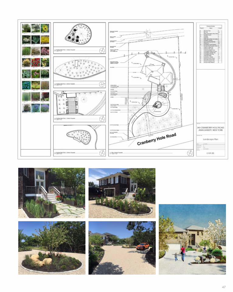
47
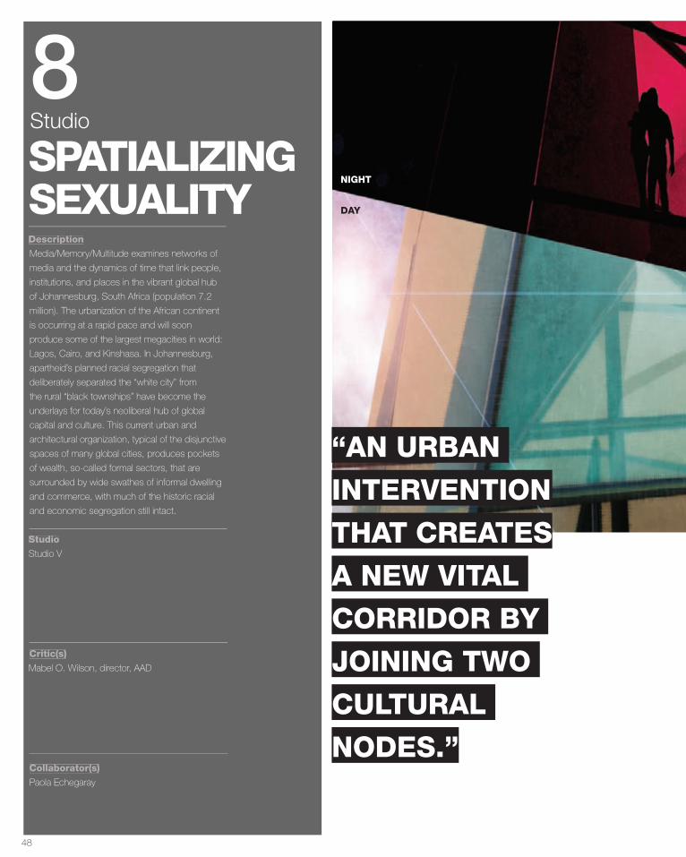
48
Description
Studio
Critic(s)
Collaborator(s)
Media/Memory/Multitude examines networks of
media and the dynamics of time that link people,
institutions, and places in the vibrant global hub
of Johannesburg, South Africa (population 7.2
million). The urbanization of the African continent
is occurring at a rapid pace and will soon
produce some of the largest megacities in world:
Lagos, Cairo, and Kinshasa. In Johannesburg,
apartheid’s planned racial segregation that
deliberately separated the “white city” from
the rural “black townships” have become the
underlays for today’s neoliberal hub of global
capital and culture. This current urban and
architectural organization, typical of the disjunctive
spaces of many global cities, produces pockets
of wealth, so-called formal sectors, that are
surrounded by wide swathes of informal dwelling
and commerce, with much of the historic racial
and economic segregation still intact.
Studio V
Mabel O. Wilson, director, AAD
Paola Echegaray
SPATIALIZINGSEXUALITY
8Studio
DAY
NIGHT
A
“AN URBAN
INTERVENTION
THAT CREATES
A NEW VITAL
CORRIDOR BY
JOINING TWO
CULTURAL
NODES.”
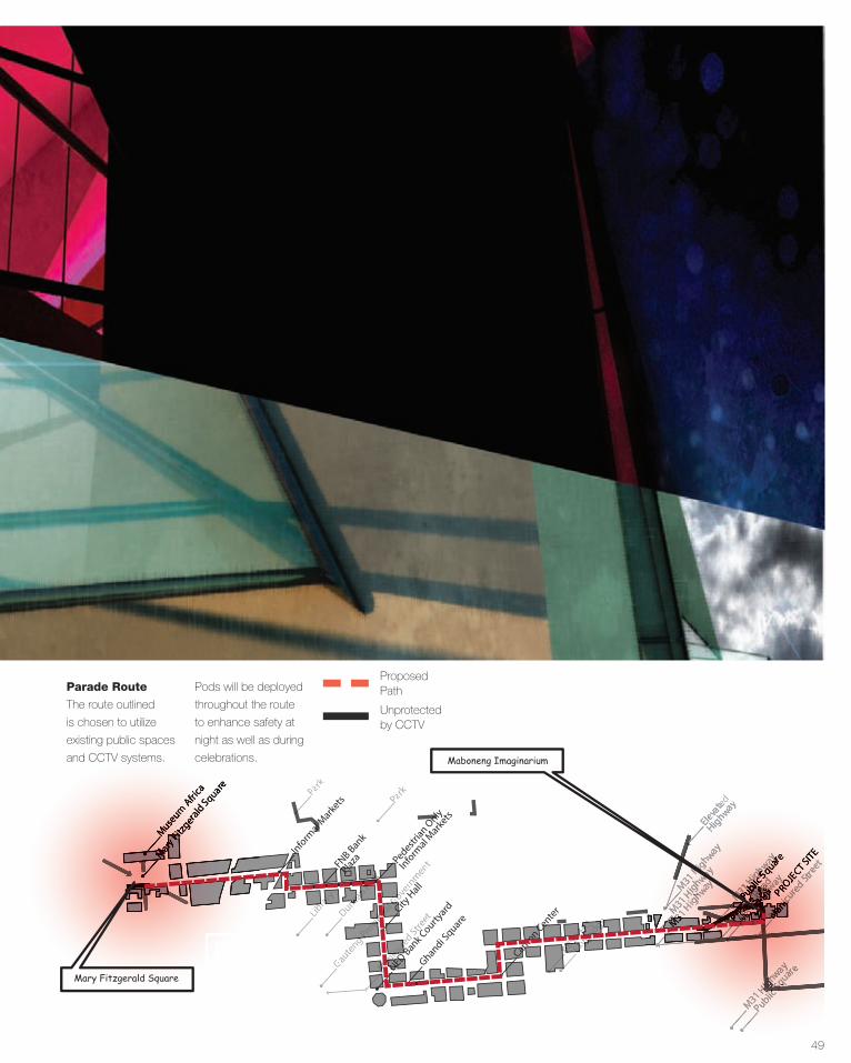
49
ParkCity
Hall
Ghandi Square
NED Bank Courty
ard
Gauteng
eng eng PPPro
vincial
vincial
vincial
vincial
vincial
vincial
vincial GGGGG
ooovern
ment
Duncan
uncan
uncan
uncan
uncan PPPPaaaarrrrkkkkk
FNB Bank
Plaza
ParkLibLibLib
rrraaarry
Inform
al Marke
ts
Mary
Fitzg
erald Square
Museum
Afri
ca
Carlton Cente
r
ted y
ABSA HQ
ABSA HQ
ABSA HQ
ABSA HQ
ABSA HQ
ABSA HQ
ABSA HQ
ABSA HQ
ABSA HQ
SSSkkkABSA HQ
kABSA HQ
ABSA HQ
kABSA HQ
ABSA HQ
kABSA HQ
ybybybybyb
ABSA HQ
yb
ABSA HQ
ABSA HQ
yb
ABSA HQ
ABSA HQ
yb
ABSA HQ
rrridge
idgeidgeidgeidge
ABSA HQ idge
ABSA HQ
Public Square
MMManicuanicuanicuanicuanicu
rrred
ed ed Stre
et
Pedestrian O
nly
Inform
al Marke
ts
ark
PROJECT SITEMMM
aaarrry y y FFF
itzge
itzgerald Square
Museum
Afri
ca
M31 Highway
Elevated
HighwayM31 H
ighway
M31 M31 M31 M31 M31 M31 HHHHHH
igigigigigighhhway
M31 HHigighhway
M31 Highway
M31 M31 M31 H
ighig
hig way
MMMMManicuanicuanicuanicuanicu
red Stre
et
PPPPPrrrr M31
r M31 iii
M31 i
M31 M31
iM31 M31
iM31 vvM31 vM31 M31 vM31 aaM31 aM31 M31 aM31 tttM31 tM31 M31 tM31 e e e e
He HHe HHe H
R igR igigR igoadoadoadoad
igoad
igigoad
igigoad
ighoadhhoadhPM31
PM31 ublic
ublic
ublic
M31 ublic
M31 Hublic
Higublic
ig Sig SighSh quayquay ry ry e
Public
ublic ig
ublic ig SSqua
quarePROJE
CT SITE
Mary Fitzgerald Square
Maboneng Imaginarium
CThe route outlined
is chosen to utilize
existing public spaces
and CCTV systems.
Pods will be deployed
throughout the route
to enhance safety at
night as well as during
celebrations.
Parade Route
B
Proposed Path
Unprotectedby CCTV

50
Part
CBD as
Sexual Epicenter
Mapping
as CCTV
CCTV on pole
CCTV on building
Bus stop CCTV
Private surveillance
The remapped CBD visualizes the city as a heat
map identifying critical areas of safety as well as
possible areas of privacy invasion.
Utilizing Grasshopper and Rhino to create
visualization.
We researched topics that attribute to the overall
sexual health outlook of Johannesburg. By
overlaying the spatialized topics on the map of
the city, the CBD emerges as the epicenter of
activity.
A
The herbalist shopis just a few more
meters.Chick‛s got anice rack!
Mary
Fitzgerald Square
This proposal is an intervention to an existing
public space. The intervention is a new entry to
the Museum Africa which was previously entered
after crossing a street. The new square will be
the staging area for parades and as an everyday
public market.
Movement
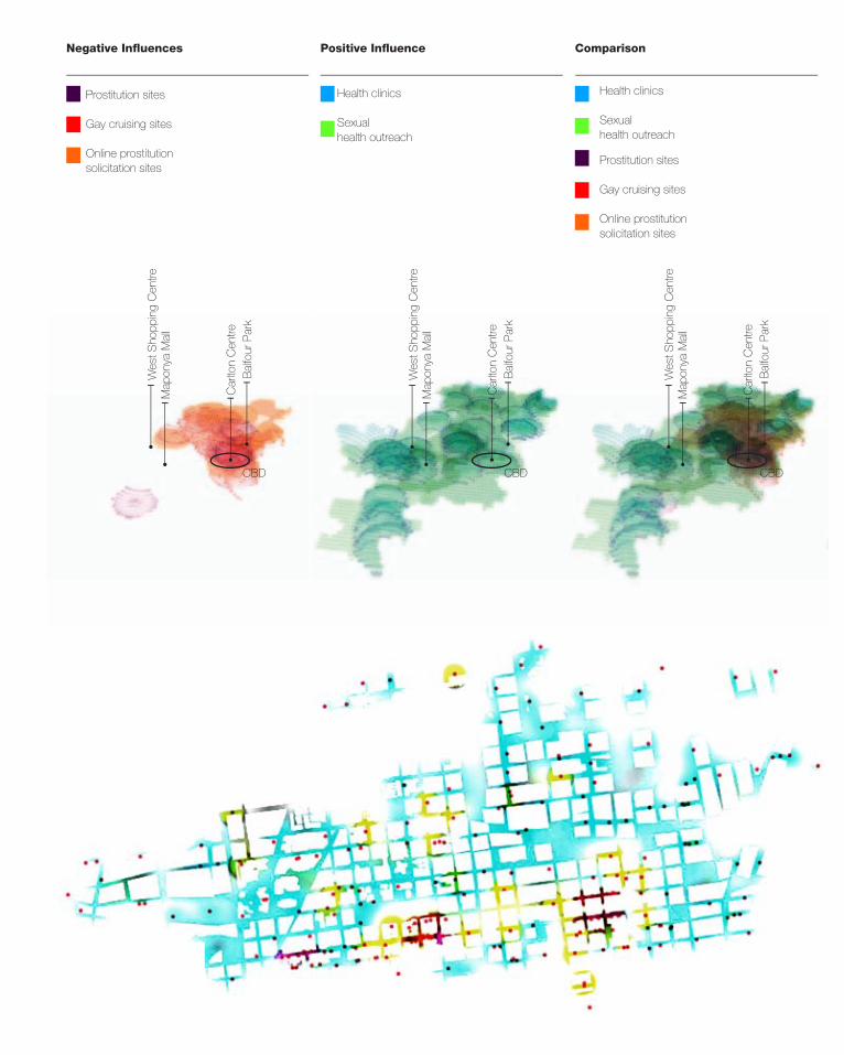
51
Negative Influences ComparisonPositive Influence
Health clinics
Sexual health outreach
Health clinics
Sexual health outreach
Prostitution sites
Gay cruising sites
Online prostitution solicitation sites
Prostitution sites
Gay cruising sites
Online prostitution solicitation sites
Wes
t Sho
ppin
g C
entre
Wes
t Sho
ppin
g C
entre
Wes
t Sho
ppin
g C
entre
Map
onya
Mal
l
Map
onya
Mal
l
Map
onya
Mal
l
Car
lton
Cen
tre
Car
lton
Cen
tre
Car
lton
Cen
tre
Bal
four
Par
k
Bal
four
Par
k
Bal
four
Par
k
CBD CBD CBD
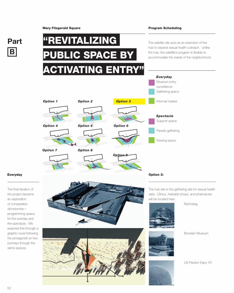
52
Mary Fitzgerald Square
Part
Program Scheduling
Option 3:
The satellite site acts as an extension of the
hub to expand sexual health outreach. Unlike
the hub, the satellite’s program is flexible to
accommodate the needs of the neighborhood.B
Option 3
Option 6
Option 9
Option 2
Option 5
Option 8
Option 1
Option 4
Option 7
The hub site is the gathering site for sexual health
data. Clinics, herbalist shops, and pharmacies
will be located here.
Reichstag
Brooklyn Museum
US Pavilion Expo ‘67
Museum entry,
surveillance
Gathering space
Informal market
Everyday
Support space
Parade gathering
Viewing space
Spectacle
The final iteration of
the project became
an exploration
of comparative
dichotomies—
programming space
for the everday and
the spectacle. We
explored this through a
graphic novel following
the protagonist on two
journeys through the
same spaces.
Everyday
“REVITALIZING
PUBLIC SPACE BY
ACTIVATING ENTRY”
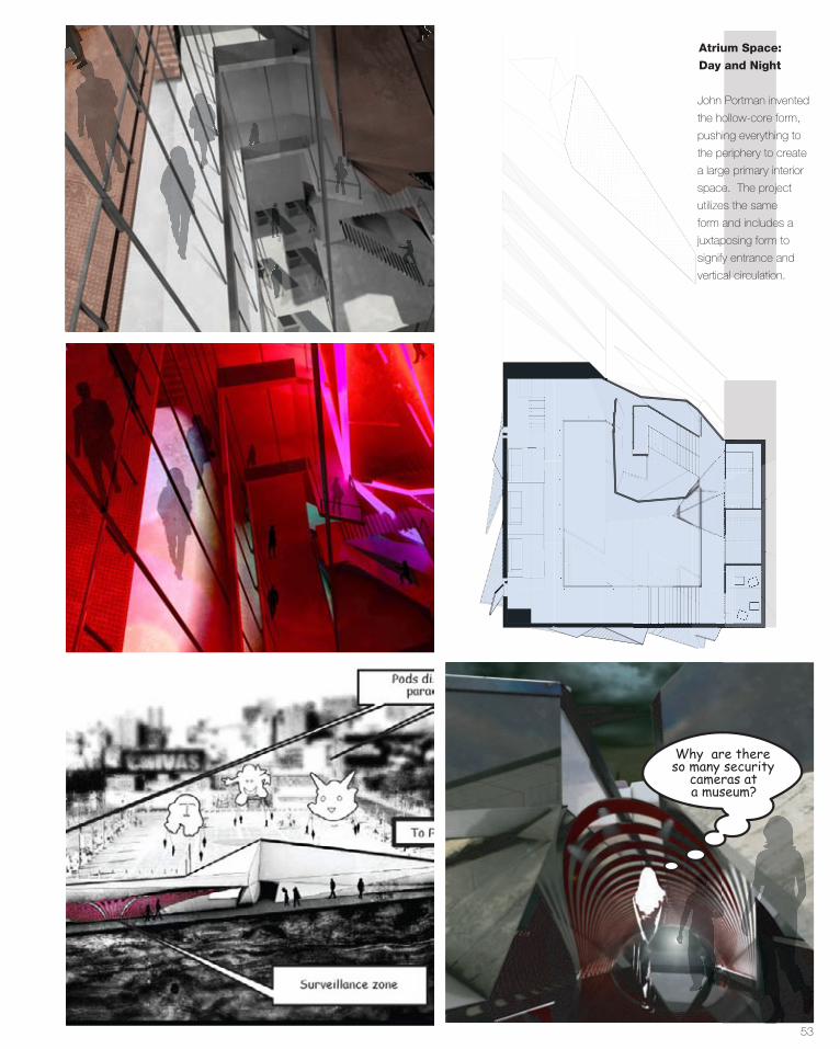
53
The bar is up on the roof.It‛s open bar for another
thirty minutes
YEAH!!!
Top Floor
Why are there so many security
cameras at a museum?
John Portman invented
the hollow-core form,
pushing everything to
the periphery to create
a large primary interior
space. The project
utilizes the same
form and includes a
juxtaposing form to
signify entrance and
vertical circulation.
Atrium Space:
Day and Night

54
Maboneng Imaginarium Program
Spectacle spaces to Open Rooftop
The building acts as a funnel to direct people to
the roof during spectacle. People can choose
a direct short path within the lighted core, or
take the indirect route through exhibit space and
private rooms.
Exhibition Spaces
Surveillance Basement
PartC
Semi-Public, Slow Path
Public, Fast Path
To Roofscape
The user’s destination
is the rooftop of the
adjacent buildings.
The maboneng district
is known for rooftop
nightlife, because of
this, the building itself
acts as the vertical
conveyance to that
space.
Rooftop Event
Space: Route
Termination
Do I hear something in that pod? I can‛t see anything,
only shadows.
Mmmmm...
The herbalist shopis just a few more
meters.Chick‛s got anice rack!
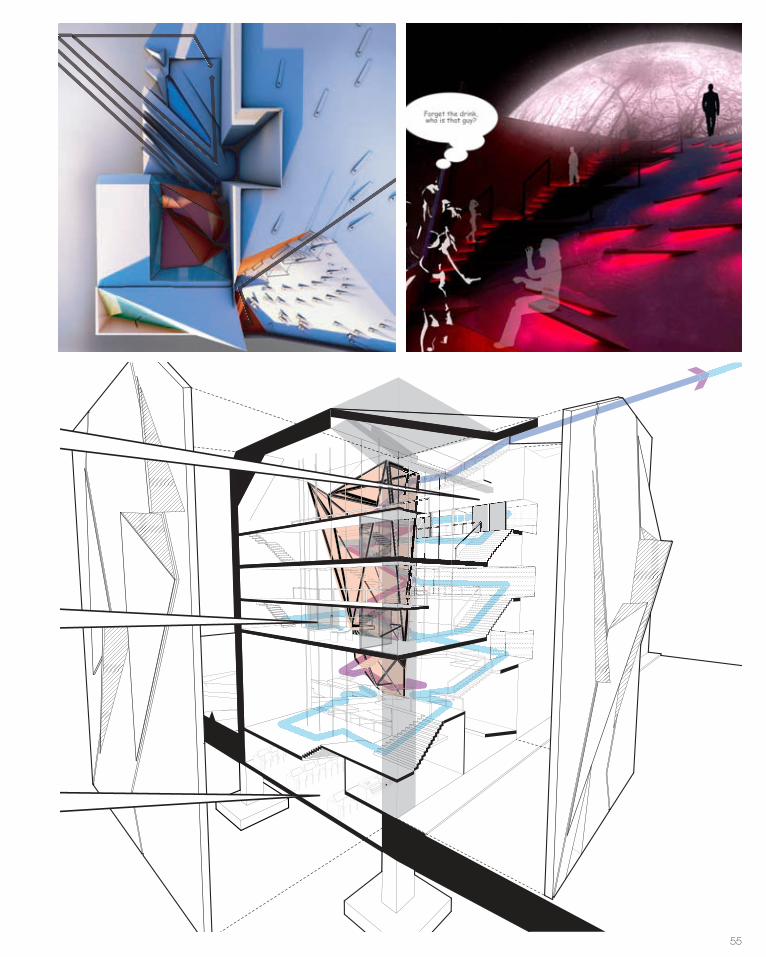
55
Semi-Public, Slow Path
Public, Fast Path
To Roofscape
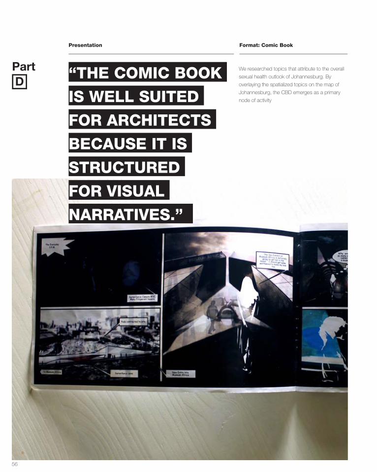
56
Presentation
Part
Format: Comic Book
We researched topics that attribute to the overall
sexual health outlook of Johannesburg. By
overlaying the spatialized topics on the map of
Johannesburg, the CBD emerges as a primary
node of activity
D“THE COMIC BOOK
IS WELL SUITED
FOR ARCHITECTS
BECAUSE IT IS
STRUCTURED
FOR VISUAL
NARRATIVES.”

57
New Entry into Museum Africa
Pods dispersed
Surveillance Camera #32,Mary Fitzgerald Square
To Parade Route
Surveillance zone
The Spectacle6:45 PM
I‛m excited for the Jozi Carnival, I hope my costume
is super sexy.
The bar is up on the roof.It‛s open bar for another
thirty minutes
YEAH!!!
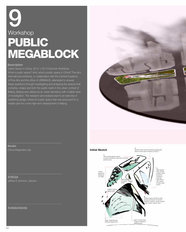
58
Description
Studio
Critic(s)
Collaborator(s)
Urban Space in China, 2012 + 2013 Summer Workshop
What is public space? And, what is public space in China? The joint
international workshop, in collaboration with the Central Academy
of Fine Arts and the office of URBANUS, attempted to answer
these questions through investigating and analyzing the spaces that
comprise, shape and form the public realm in the urban context of
Beijing. Beijing was utilized as an urban laboratory with multiple sites
of investigation. The research and analysis lead to an exercise of
redefining design criteria for public space that was proposed for a
master plan for a new high-tech development in Beijing.
China Megacities Lab
Jeffrey R Johnson, director
PUBLICMEGABLOCK
9Workshop
closed green hill, backdrop for stage
opening to courtyard / “garden exhibit
open square with covered outdoor cafes & ground fountains; evening:light shows can convert to have temp stores
stage / amphitheater facing 45 degrees left
path circumventing stage to exhibition / pavillion area
semi-private garden spaces at various elevations with main exit from pavillion area
exbition space with glass walls pourous entrances to covered pavillion in yellow, can be used for larger events / expos / fairs
artificial water stream following subway path down to meet water fountains in block 2
1
3
7
4
2
6
stadium seating against wall
Initial Sketch
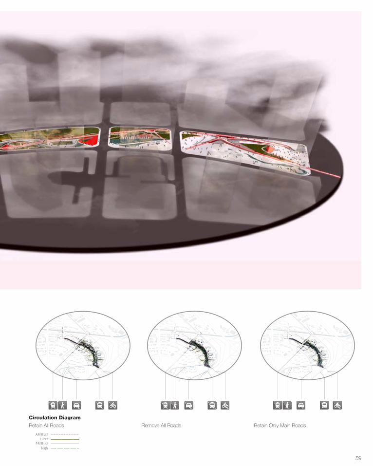
59
AM RushLunch
PM Rush Night
Maintain Existing RoadsCirculation Diagram
Unified SIte Maintain Existing Main Roads• Existing Site• Site & Flows• Flows
• Existing Site• Site & Flows• Flows
• Existing Site• Site & Flows• Flows
Transportation Mode
Maintain Existing RoadsCirculation Diagram
Unified SIte Maintain Existing Main Roads• Existing Site• Site & Flows• Flows
• Existing Site• Site & Flows• Flows
• Existing Site• Site & Flows• Flows
Transportation Mode
Maintain Existing RoadsCirculation Diagram
Unified SIte Maintain Existing Main Roads• Existing Site• Site & Flows• Flows
• Existing Site• Site & Flows• Flows
• Existing Site• Site & Flows• Flows
Transportation Mode
Maintain Existing RoadsCirculation Diagram
Unified SIte Maintain Existing Main Roads• Existing Site• Site & Flows• Flows
• Existing Site• Site & Flows• Flows
• Existing Site• Site & Flows• Flows
Circulation Diagram
Retain All Roads Remove All Roads Retain Only Main Roads
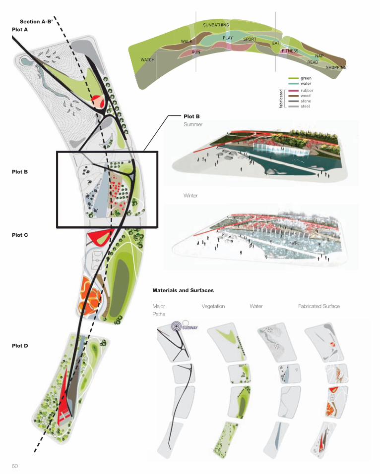
60
Summer
Winter
Vegetation Water Fabricated Surface
Plot B
WATCHWALK
SUNBATHING
PUBLIC PRIVATE
RUN
PLAY EAT
MARKET
SPORTSFITNESS READ SHOPPING
NAP
greenwater
rubber
fabricated
woodstonesteel
WATCH
WALK
RUN
SUNBATHING
PLAY SPORTEAT
FITNESSNAP
READSHOPPING
Major
Paths
Materials and Surfaces
Section A-B’
Plot A
Plot B
Plot C
Plot D
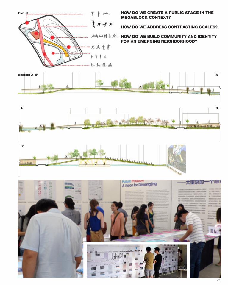
61
Section A-B’ A
BA’
B’
Plot C HOW DO WE CREATE A PUBLIC SPACE IN THE MEGABLOCK CONTEXT?
HOW DO WE ADDRESS CONTRASTING SCALES?
HOW DO WE BUILD COMMUNITY AND IDENTITY FOR AN EMERGING NEIGHBORHOOD?