Embed Size (px)
Citation preview
Architecture
Chapter 3
Buses, CPU and I/O system
• ISA specifies a computer from a programmers point of view
• HSA specifies its organization and performance.
Buses
• Local buses
• System buses
• Hybrid (expanded local buses)
Local Bus
• Part of a device (connected directly to a device)– Address bus
• specialized in purpose
• unidirectional
– Data bus• General purpose, and bidirectional
– Control bus• Carry signals
System Buse
• Independent functional components
• Each system bus has its on control circuit (Bus controller)
• Within each controller is an arbiter– processes requests to use the bus.
• The controller may be distributed among the devices that use the bus.
Expanded Local Bus
• Mostly in microcomputers
• Local buses with special extensions for use outside the CPU
• They are similar to system buses in that they provide standardized control signals in addition to the data and address pathways.
• They are local to CPU in that CPU’s clock and timing circuits regulate them.
• Processor specific
Bus Transfers and Control Signals
• Bus transfer– transmission of information across a bus– Types of transmission bus cycles:
• memory read, memory write, I/O read, I/O write, and Interrupt
– Transfer takes place in stages called BUS STATES• Each cycle has well defined sequence of bus states.
• A clock regulates the bus sates
• a bus controller may have its own clock or use a system wide clock
Bus transfers contd.
• Devices that can compete for a system or expanded local bus are called BUS MASTERS.
• When a Bus Master is present other devices such as memory are slaves
• Slaves respond to requests by bus masters.
How does a device use the bus?
• Bus-request signal is sent to the arbitrator– This request is made on a bus-request line
• Arbitrator grants the request and sends a accept signal back– accept signal is sent on a bus-grant line– The device that is granted acceptance that device becomes the
bus master for one cycle• Only the bus master and those devices the bus master selects as
slaves may sent information to the bus.• Requesting and granting permission is called the BUS
PROTOCOL• There are various protocols used today.

cpuRAENaddress
Refer to page 123 in the text book.
Bus cycle types
• for reads -- line R is asserted– memory places data on the bus
• for writes - line W is asserted– CPU places the data on the bus
CPU
• Register set– already discussed
• ALU
• control unit
ALU
• Arithmetic, logical and shift operations
• All three could be in one functional unit or two or more units.
• Multiplexors are used when more than one functional unit exists to share the line.
• Also may have temporary registers and status set of flags
ALU contd• Status register
– carry (C)– overflow (V) negative result (N)– zero result (Z)
• Dedicated control bus– carries control signals from the control unit to
ALU
• Dedicated status bus– carries status signals from ALU to control unit
Control unit
– purpose: control system operations by routing the selected data items to the selected processing hardware at the right time. A control unit’s responsibility to drive the associated processing hardware by generating a set of signals that are synchronized with a master clock.
• Control unit interprets instructions.
• It sequences instructions
– In the interpretation phase, the control unit reads instructions from the memory using PC as a pointer. It then recognizes the instruction type, gets the necessary operands, then routes them to the appropriate functional units of the execution unit to perform the desired operation, and the results are routed to the specified destination.
Control Unit• generates the control signals that regulate
the computer.
• Microorders are the signals sent over dedicated lines to control individual components and devices. *
• microinstruction: set of microorders issued by the control unit at one time is called a microinstruction.
• Microprogram: sequence of microinstructions to handle a machine instruction.
• Fetch from memory the next (PC) instruction to be executed.
• Place it in the instruction register (IR)
• Increment PC
• Decode and execute the instruction just fetched.
• (see page 127, figure 3.5)
Control Unit operation
• microprogrammed– easier to design (complex instruction sets for
very little cost)– slower than conventional (so can’t use in high
performance CPUs)
• conventional– hard wired
Two types of control unit
– Microprogramming gives a well-structured control organization.
– Programming structures can be incorporated.– Changes and improvements can easily be made.– Even a small change in the hardwired means
redesigning the whole chip.
• Page 129 figure 3.7– Control unit fetches an instruction from memory– it then converts the instruction into a series of
microinstructions• conversion is done by a microprogram tanslator *• microinstructions are fetched from its own memory or
main memory.
– These microinstructions are converted to microorders by Microinstruction processor.
Microprogrammed control units
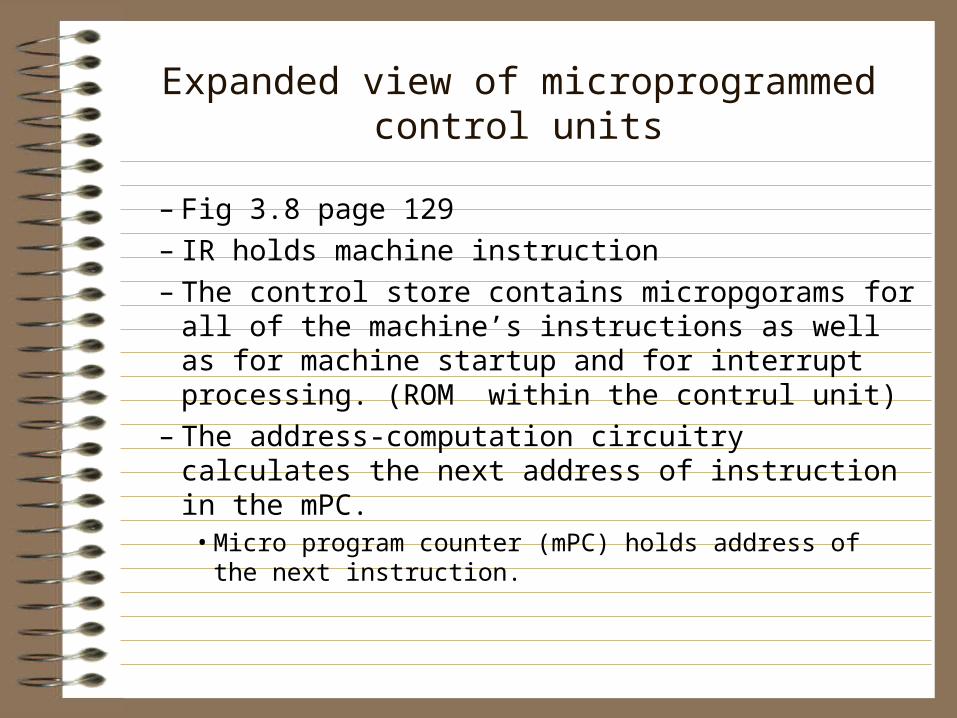
– Fig 3.8 page 129– IR holds machine instruction– The control store contains micropgorams for all of
the machine’s instructions as well as for machine startup and for interrupt processing. (ROM within the contrul unit)
– The address-computation circuitry calculates the next address of instruction in the mPC.
• Micro program counter (mPC) holds address of the next instruction.
Expanded view of microprogrammed control units
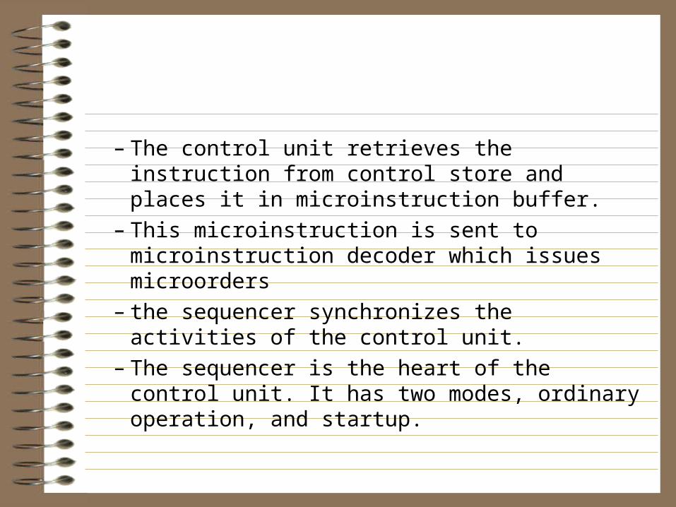
– The control unit retrieves the instruction from control store and places it in microinstruction buffer.
– This microinstruction is sent to microinstruction decoder which issues microorders
– the sequencer synchronizes the activities of the control unit.
– The sequencer is the heart of the control unit. It has two modes, ordinary operation, and startup.
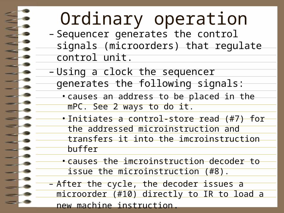
– Sequencer generates the control signals (microorders) that regulate control unit.
– Using a clock the sequencer generates the following signals:
• causes an address to be placed in the mPC. See 2 ways to do it.
• Initiates a control-store read (#7) for the addressed microinstruction and transfers it into the imcroinstruction buffer
• causes the imcroinstruction decoder to issue the microinstruction (#8).
– After the cycle, the decoder issues a microorder (#10) directly to IR to load a new machine instruction.
Ordinary operation
– Clear all registers– Hardware generated address or (pointer to an
address )is placed in PC (address is called a reset vector).
Machine startup
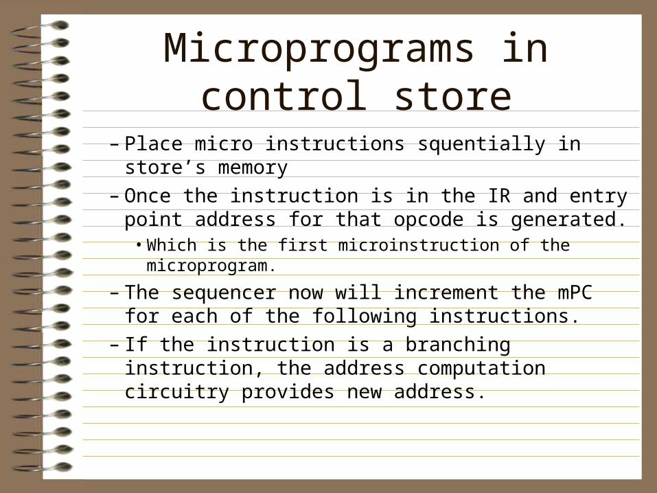
– Place micro instructions squentially in store’s memory
– Once the instruction is in the IR and entry point address for that opcode is generated.
• Which is the first microinstruction of the microprogram.
– The sequencer now will increment the mPC for each of the following instructions.
– If the instruction is a branching instruction, the address computation circuitry provides new address.
Microprograms in control store
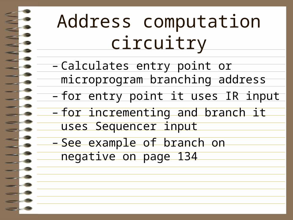
– Calculates entry point or microprogram branching address
– for entry point it uses IR input– for incrementing and branch it uses Sequencer
input– See example of branch on negative on page 134
Address computation circuitry
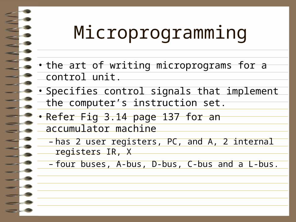
• the art of writing microprograms for a control unit.
• Specifies control signals that implement the computer’s instruction set.
• Refer Fig 3.14 page 137 for an accumulator machine– has 2 user registers, PC, and A, 2 internal registers
IR, X– four buses, A-bus, D-bus, C-bus and a L-bus.
Microprogramming
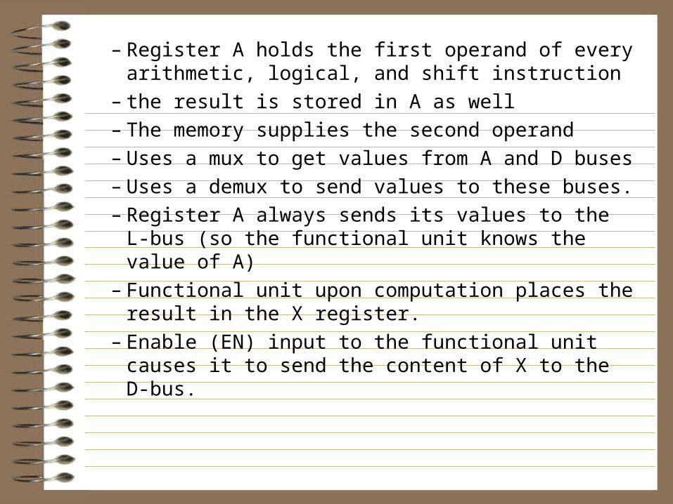
– Register A holds the first operand of every arithmetic, logical, and shift instruction
– the result is stored in A as well– The memory supplies the second operand– Uses a mux to get values from A and D buses– Uses a demux to send values to these buses.– Register A always sends its values to the L-bus
(so the functional unit knows the value of A)– Functional unit upon computation places the
result in the X register.– Enable (EN) input to the functional unit causes
it to send the content of X to the D-bus.
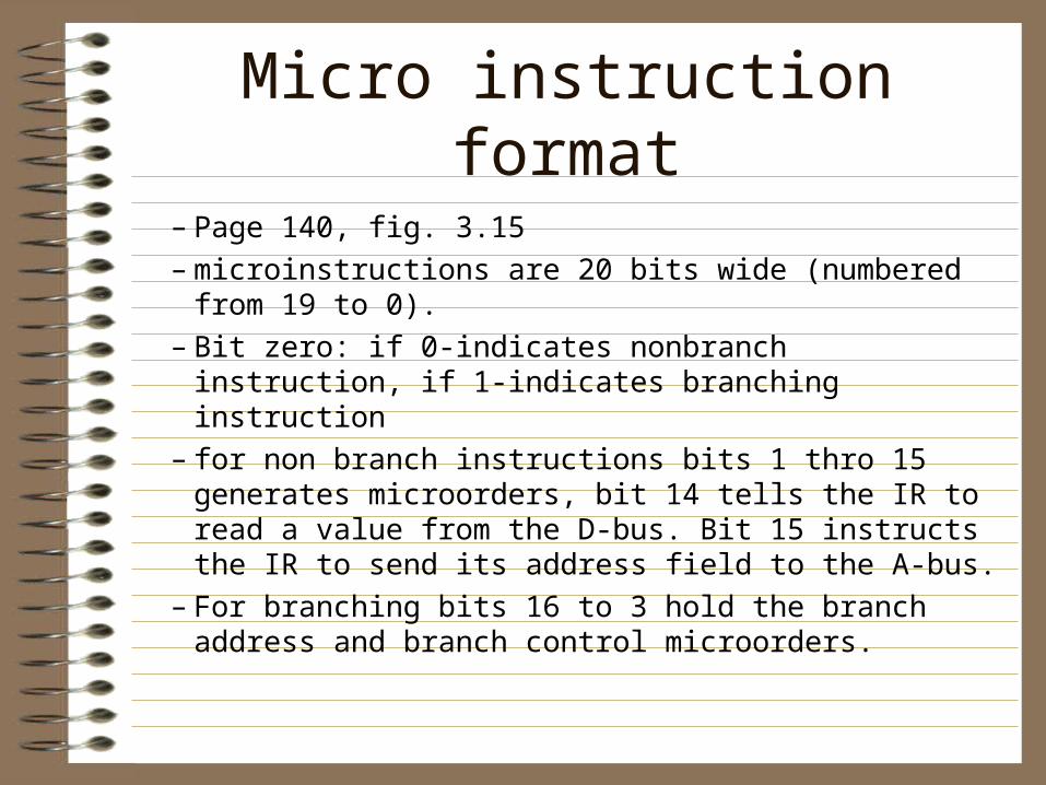
– Page 140, fig. 3.15– microinstructions are 20 bits wide (numbered from 19 to
0).– Bit zero: if 0-indicates nonbranch instruction, if 1-indicates
branching instruction– for non branch instructions bits 1 thro 15 generates
microorders, bit 14 tells the IR to read a value from the D-bus. Bit 15 instructs the IR to send its address field to the A-bus.
– For branching bits 16 to 3 hold the branch address and branch control microorders.
Micro instruction format
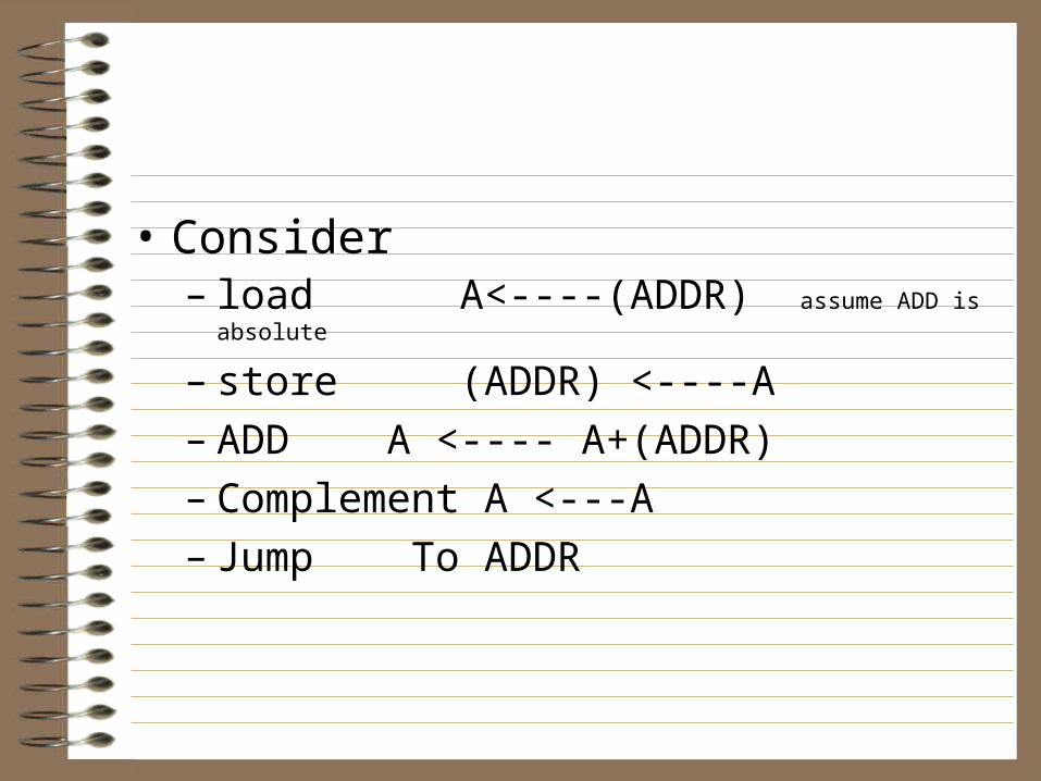
• Consider– load A<----(ADDR) assume ADD is absolute
– store (ADDR) <----A– ADD A <---- A+(ADDR)– Complement A <---A– Jump To ADDR
Instruction fetch
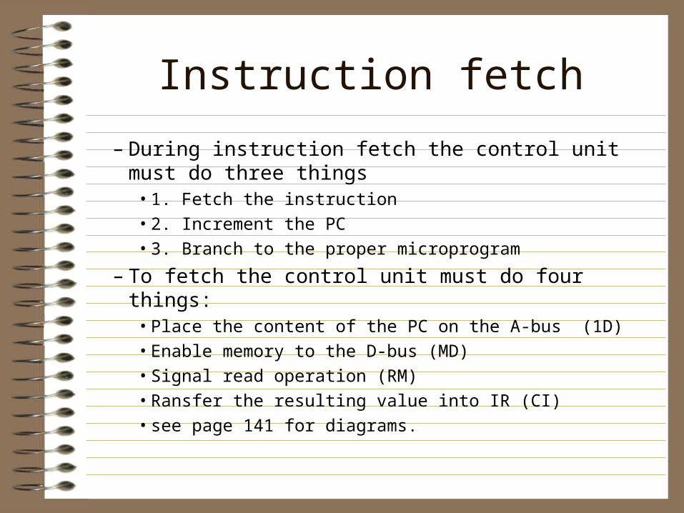
– During instruction fetch the control unit must do three things
• 1. Fetch the instruction• 2. Increment the PC• 3. Branch to the proper microprogram
– To fetch the control unit must do four things:• Place the content of the PC on the A-bus (1D)• Enable memory to the D-bus (MD)• Signal read operation (RM)• Ransfer the resulting value into IR (CI)• see page 141 for diagrams.
Assignment
• do COMPLEMENT and ADD operations like the previous slide.
• (5 points each)
Hardwired approach
– circuit is obtained by physically connecting typical components such as gates and flip flops.
Exception-processing Hardware and instructions.
– Exceptions are branches initiated by special exceptions processing hardware.
– There are two types of exception - interrupts and traps
– Interrupts• asynchronous branches triggered by events external
to the program.
• Asynchronous because computer’s clock does not control them.
• Examples, I/O interrupts: Tells the CPU that an I/O device requires attention.
• Console interrupts: an operator may halt the operation through console keyboard
Traps
• Programs use trap to communicate with the OS.– Similar to interrupts, except that program events
trigger them.– So they are synchronous. Example, arithmetic
overflow or illegal op code or memory protection violations.
– Multiprogramming systems need traps to prevent one program from modifying another’s memory.
Exception handlers
• trap handlers• interrupt handlers• Exceptions are handled based on the run-time
state: processor context and memory context.– Processor context is the state of the CPU’s program-
visible registers.• Visible registers are PC, processor status bits and other
operational registers.
– Memory context is the state of program’s memory.
– Exception handlers should preserve as much processor context as possible.
– At the minimum the PC and the processor status flags should be saved.
– It is best to save the entire processor register set.• It can be done by pushing on a stack or saving in a
special memory save area.
– Upon return from interrupt all saved info is restored and returns control to the interrupted program.
• Requirements for exceptions are these:– The CPU needs special hardware, operations
and instructions to save and restore key registers
– Hardware must include a way of invoking these operations and instruction.
– Operating system must provide a way of allocating and deallocating memory for interrupted programs.
– The hardware must know where to transfer control and where to return to.
Priority exceptions and exception vectors
– Interrupts can be initiated by - I/O devices, interval timers, power supply, etc.
– Traps can be initiated by - memory-protection hardware, the ALU, and control unit
– The exception hardware must be able to generate proper exception-handler address for each type of exception.
Interrupts
– each device requesting and interrupt raises and interrupt-request signal on a dedicated interrupt request line. (IRQ)
– This signal sets an interrupt-code flag indicating that a device of that priority has requested an interrupt.
– All such interrupt code flags take together is called Interrupt-code Register (ICR).
– In order for the CPU not to handle another IRQ while handling one, interrupt-disable flip-flops are installed. (see page 147)
– After the exception hardware transfers control to the exception handler, it must determine which device actually request the interrupt.
– Methods used to determine who requested the interrupt:
• 1. interrupt polling. Exception handler asks each device of a given priority who requested it.
• 2. Device places a device-specific code in a register that interrupt handler can look at.
– To transfer control to the correct interrupt handler, the exception processing hardware must determine an address for each exception. This is done by:
• 1. Automatically generate the absolute address for the first instruction of the exception handler by decoding the value in the ICR.
• 2. Vectored exceptions - Indexed indirect address to branch to exception handlers. The exception handler address is kept in a exception vector table. Each exception has a exception vector. Each exception has a number, which becomes the offset.
– When a system use the vectored exceptions, the operating system places the exception-vector table in main memory; usually in the same place so it can find it easily.
– If the vector table is kept at different locations, then there must be a exception-vector-table address register, which points to that location.
– To process interrupts, the control unit performs a conditional branch to fetch the microcode. When the interrupt-pending signal is true, the address computation circuitry modifies the branch address.
– The exception initiation microcode is similar to any other microcode.
Exception initiation
– Interrupt mask is used to prevent certain types of interrupts from occurring automatically.
– The Mask is kept in the interrupt-mask register (IMR). This mask indicates which interrupts are allowed.
– When the hardware masks an exception, the CPU ignores it or queues it for later processing.
– Maskable exceptions are: I/O interrupts, arithmetic exceptions, and memory bound exceptions.
Exception masking
I/O SYSTEM
– the set of I/O devices in the system.• Printers, video displays and associated interfaces
• interfaces isolate CPU from unnecessary tasks. They control the devices.
• Keyboard, mouse, joysticks, scanners, etc. are input devices
CPU controlled I/O
Memory System Architecture
• First generation - Mercury delay lines– 404 micro second delay
• Second Generation - Core memory– 1000 nano seconds
• After - solid state memory– 60 to 150 ns or faster
RAM
– Random access memory• every word can be accessed within the same amount of
time
– Three buses to each RAM chip• unidirectional address bus
• bidirection data bus
• Control lines
– Organized using high-order or low order interleave• interleaved so that each byte is stored in pair of chips
Types of memory
– ROMs - switches are set, can not be alterd– PROMs - high current can burn fuses
manufactured into chips. Can not be altered once programmed.
– EPROM - can be erased using UV light. May reprogram numerous times (<100)
SRAM (STATIC RAM)
– Once written, the value remains in memory• no need to refresh
– Used in CPU registers and other high speed storage devices
• May be used for cache memory in high end systems
– Currently the fastest and most expensive
DRAM (DYNAMIC RAM)
– A capacitor holds charge and a transister– Capacitor will drain charge so must be
recharged every few milliseconds– Slower and cheaper than SRAM– Destructive reads. When reading DRAM the
the current is discharged. The circuitry on the chip automatically restores the value after the read. (SRAM is not destructive).
Main Memory System– When small memory was available we used
overlays.• Talk about overlays
– Virtual Memory• Main memory and secondary memory are
considered to contigous
• The OS maintains special tables that keep track of where each part of the program reside in main memory and in external storage
Memory hierarchy of multilevel storage system
– Registers– internal cache (in CPU-SRAM)– external cache (outside CPU-SRAM or DRAM)– Main Memory– Secondary Memory
Program relocation and Memory Protection
– Crucial features needed for multipgroamming:• program relocation
• memory protection
• privileged modes of operation
• timer interrupts
Program relocation
– ability of OS to move the program by providing a RELOCATION OFFSET
– initial program relocation • where the operating system first places the program
using the offset
– dynamic program relocation• program is moved after starting execution
Memory protection
– protecting memory allocated to one program from being used by another.
– The operating system may assign a value (access key) for each executing program.
– The hardware also holds this access key in the psw (program status word)
– When a device initiates memory access, the memory protection hardware compares the access key of the requesting program to the access key associated with the memory.
Privileged mode
– When operating system takes control it is in the privileged mode
• during privileged mode the user has no access to privileged instructions
– when the control is transferred to an application program, it is in the unprivileged mode

Cache Memory
– during a memory read, it also reads adjacent memory locations and places the data in the cache
– cache entries include address tags where the data came from.
Fixed-partition multiprogramming
– OS partitions main memory into partitions– In the fixed-partition the size and locations do
not change with time.– Physical address = logical address+partition
address
Variable-partition multiprogramming
– OS can maintain partitions with variable boundaries
– the idea is to establish a partition only when a job is loaded into memory
– The size of the memory can exactly match the size of the job.
– When a job stops execution, that memory is freed. This freed memory is called a hole (causing fragmenation).
– Wholes are filled when OS allocates them to another program.