Embed Size (px)
Citation preview
Getting Started with the NI LabVIEW Embedded Module for ADI Blackfin ProcessorsVersion 2.0
The NI LabVIEW Embedded Module for ADI Blackfin Processors is a comprehensive graphical development environment for embedded design. Jointly developed by Analog Devices and National Instruments, this module seamlessly integrates the LabVIEW development environmentand Blackfin embedded processors.
This module builds on NI LabVIEW Embedded technology, which facilitates dataflow graphical programming for embedded systems and includes hundreds of analysis and signal processing functions, integrated I/O, and an interactive debugging interface. With the Embedded Modulefor Blackfin Processors, you can enable cache, optimize linking, and view live front panel updates using JTAG, serial, or TCP/IP, as well as use VisualDSP++ compiler options through LabVIEW. The Embedded Module for Blackfin Processors includes the LabVIEW C Code Generator, which generates C code from the LabVIEW block diagram.
Engineers and scientists can lower development costs, achieve faster development times, and still deliver a high performance embedded processing solution with the Embedded Module for Blackfin Processors.
ContentsWhat’s New in the Embedded Module for Blackfin Processors ............ 2System Requirements.............................................................................. 3Installing the Embedded Module for Blackfin Processors...................... 3Installing the EZ-KIT Lite or Emulator .................................................. 5Upgrading to the Embedded Module for Blackfin Processors 2.0 ......... 6
Embedded Project Manager............................................................. 6Upgrading Blackfin VIs and Embedded Projects ............................ 6Migrating Custom Linker Description Files .................................... 8
Tutorial.................................................................................................... 9Creating the LabVIEW Project........................................................ 9
™
Embedded Module for Blackfin Processors 2 ni.com
Creating the Front Panel...................................................................13Creating the Block Diagram.............................................................14Configuring the Target and Debugging Options ..............................16Creating the ADSP-BF537 Build Specification ...............................18Building, Downloading, and Running a Blackfin Application ........23Debugging with Breakpoints and Probes .........................................24
Where to Go from Here ...........................................................................26
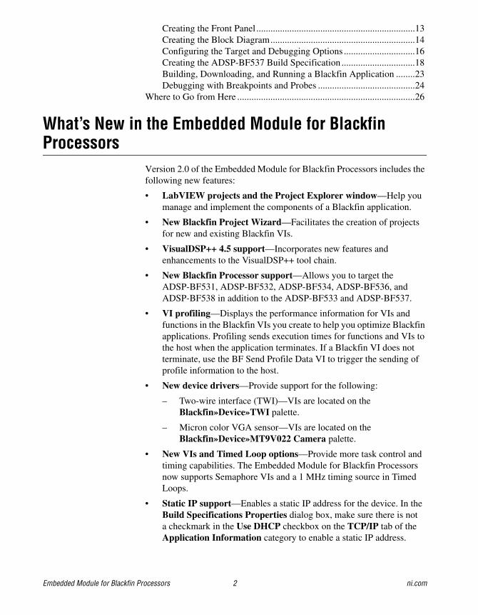
What’s New in the Embedded Module for Blackfin Processors
Version 2.0 of the Embedded Module for Blackfin Processors includes the following new features:
• LabVIEW projects and the Project Explorer window—Help you manage and implement the components of a Blackfin application.
• New Blackfin Project Wizard—Facilitates the creation of projects for new and existing Blackfin VIs.
• VisualDSP++ 4.5 support—Incorporates new features and enhancements to the VisualDSP++ tool chain.
• New Blackfin Processor support—Allows you to target the ADSP-BF531, ADSP-BF532, ADSP-BF534, ADSP-BF536, and ADSP-BF538 in addition to the ADSP-BF533 and ADSP-BF537.
• VI profiling—Displays the performance information for VIs and functions in the Blackfin VIs you create to help you optimize Blackfin applications. Profiling sends execution times for functions and VIs to the host when the application terminates. If a Blackfin VI does not terminate, use the BF Send Profile Data VI to trigger the sending of profile information to the host.
• New device drivers—Provide support for the following:
– Two-wire interface (TWI)—VIs are located on the Blackfin»Device»TWI palette.
– Micron color VGA sensor—VIs are located on the Blackfin»Device»MT9V022 Camera palette.
• New VIs and Timed Loop options—Provide more task control and timing capabilities. The Embedded Module for Blackfin Processors now supports Semaphore VIs and a 1 MHz timing source in Timed Loops.
• Static IP support—Enables a static IP address for the device. In the Build Specifications Properties dialog box, make sure there is nota checkmark in the Use DHCP checkbox on the TCP/IP tab of the Application Information category to enable a static IP address.
© National Instruments Corporation 3 Embedded Module for Blackfin Processors
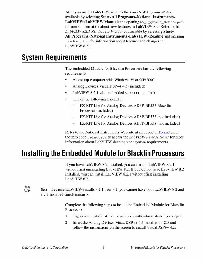
After you install LabVIEW, refer to the LabVIEW Upgrade Notes, available by selecting Start»All Programs»National Instruments»LabVIEW»LabVIEW Manuals and opening LV_Upgrade_Notes.pdf, for more information about new features in LabVIEW 8.2. Refer to the LabVIEW 8.2.1 Readme for Windows, available by selecting Start»All Programs»National Instruments»LabVIEW»Readme and opening readme.html for information about features and changes in LabVIEW 8.2.1.
System RequirementsThe Embedded Module for Blackfin Processors has the following requirements:
• A desktop computer with Windows Vista/XP/2000
• Analog Devices VisualDSP++ 4.5 (included)
• LabVIEW 8.2.1 with embedded support (included)
• One of the following EZ-KITs:
– EZ-KIT Lite for Analog Devices ADSP-BF537 Blackfin Processor (included)
– EZ-KIT Lite for Analog Devices ADSP-BF533 (not included)
– EZ-KIT Lite for Analog Devices ADSP-BF538 (not included)
Refer to the National Instruments Web site at ni.com/info and enterthe info code relnote82 to access the LabVIEW Release Notes for more information about LabVIEW development system requirements.
Installing the Embedded Module for Blackfin Processors
If you have LabVIEW 8.2 installed, you can install LabVIEW 8.2.1 without first uninstalling LabVIEW 8.2. If you do not have LabVIEW 8.2 installed, you can install LabVIEW 8.2.1 without first installing LabVIEW 8.2.
Note Because LabVIEW installs 8.2.1 over 8.2, you cannot have both LabVIEW 8.2 and 8.2.1 installed simultaneously.
Complete the following steps to install the Embedded Module for Blackfin Processors.
1. Log in as an administrator or as a user with administrator privileges.
2. Insert the Analog Devices VisualDSP++ 4.5 installation CD and follow the instructions on the screen to install VisualDSP++ 4.5.
Embedded Module for Blackfin Processors 4 ni.com
Tip If the installer does not automatically begin, double-click VisualDSP++4.5.exe on the CD to begin installation.
3. After you finish installing VisualDSP++, select Start»All Programs»Analog Devices»VisualDSP++ 4.5»Maintain this installation.
4. Select Apply a downloaded Update and click the Next button in the VisualDSP++ 4.5 - Setup wizard.
5. Open the .vdu file on the Analog Devices VisualDSP++ 4.5 installation CD, click the Next button, and follow the rest of the instructions to install the VisualDSP++ update.
6. Insert the LabVIEW 8.2.1 with Embedded Support CD and select to install the software.
Note LabVIEW 8.2.1 with embedded support is a special edition of LabVIEW 8.2.1.
7. Follow the activation instructions that appear on the screen.
You also can use the NI License Manager, available by selecting Start»All Programs»National Instruments»NI License Manager, to activate National Instruments products. Refer to the National Instruments License Manager Help, available by selecting Help»Contents in the NI License Manager, for more information about activating NI products.
8. Restart the computer when the installer prompts you and log on as an administrator or as a user with administrator privileges.
9. Insert the LabVIEW Embedded Module for Blackfin Processors 2.0 installation CD and follow the instructions on the screen.
Tip If the installer does not automatically begin, double-click setup.exe on the CD to begin installation.
10. Follow the activation instructions that appear on the screen.

© National Instruments Corporation 5 Embedded Module for Blackfin Processors
Installing the EZ-KIT Lite or Emulator
Caution Be careful when removing the board from the package and handling the board to avoid the discharge of static electricity, which might damage some components.
The EZ-KIT Lite or USB-based ICE board is designed to run as a stand-alone unit. You do not have to open the computer case.
Note You must install VisualDSP++ before you can install the Blackfin target. Refer to the Installing the Embedded Module for Blackfin Processors section for information about installing VisualDSP++.
Complete the following steps to install the EZ-KIT Lite or USB-based ICE.
1. Plug the power supply for the board into a surge-protected outlet. Connect the USB assembly for the board to the USB port on the host computer using the provided USB cable.
Figure 1 shows the location of the A/C adaptor and USB port on the Blackfin target. Refer to the ADSP-BF537 EZ-KIT Lite Evaluation System Manual in the EZ-KIT box for more detailed information about the ADSP-BF537 EZ-KIT Lite hardware.
Figure 1. Locating the A/C Adaptor and USB Port on the Blackfin Target
A/C Adaptor
USB to Host PC ANALOGDEVICES
Embedded Module for Blackfin Processors 6 ni.com
On the board, the power LED illuminates, and you might see other visible activity, such as blinking LEDs. The connection activates the Windows Found New Hardware Wizard.
2. Follow the instructions on the screen to install the software automatically. A Windows message notifies you when the new device is ready for use and the hardware installation is complete.
3. Verify that the USB monitor LED is lit. The LED is in close proximity to the USB connector. The lit LED signifies that the board is communicating properly with the host computer and is ready to run. Refer to the ADSP-BF537 EZ-KIT Lite Evaluation System Manual in the EZ-KIT box for more detailed information about the USB monitor LED.
4. For a USB-based ICE, attach the JTAG cable to the emulation target. Refer to the emulator documentation for more information about USB-based ICE.
Upgrading to the Embedded Module for Blackfin Processors 2.0
This section describes upgrade and compatibility issues for the Embedded Module for Blackfin Processors 2.0.
Embedded Project ManagerThe Embedded Module for Blackfin Processors no longer supports the Embedded Project Manager. Use the Project Explorer window instead. Refer to the Creating the LabVIEW Project section for information about using the Project Explorer window. Refer to the Upgrading Blackfin VIs and Embedded Projects section for information about converting embedded project (.lep) files.
Upgrading Blackfin VIs and Embedded ProjectsIf you created Blackfin VIs using the Embedded Module for Blackfin Processors 1.0, you must create projects and update the VIs for use with LabVIEW 8.2.1 and the Embedded Module for Blackfin Processors 2.0.
Caution National Instruments recommends you back up your files before youbegin updating your Blackfin VIs for use with the Embedded Module for Blackfin Processors 2.0. The Embedded Module for Blackfin Processors 1.0 cannot open VIsyou save in version 2.0.
The Embedded Module for Blackfin Processors includes a utility tohelp you convert LabVIEW 7.1 embedded project (.lep) files to
© National Instruments Corporation 7 Embedded Module for Blackfin Processors
LabVIEW 8.2.1 project (.lvproj) files. Complete the following steps to update embedded project files for use with LabVIEW 8.2.1 and the Embedded Module for Blackfin Processors 2.0.
1. Launch LabVIEW 8.2.1.
2. Select File»Open in the Getting Started window and navigate to the labview\Targets\ADI\Embedded\vdk\utils\Blackfin LEP
Converter\ directory.
3. Select Blackfin_LEP_Converter.vi and click the OK button to run the Blackfin LEP converter utility.
4. Complete the following steps to add the LEP file you want to import to the LabVIEW Embedded Project (*.lep) Files list.
a. Click the Add button below the LabVIEW Embedded Project (*.lep) Files list. The Select an Embedded Project to Add dialog box appears.
b. Navigate to the location of the LEP file you want to import.
c. Click the Add button. LabVIEW adds the LEP file and all the VIs associated with the LEP file to the Blackfin LEP converter utility. You can see only the LEP file in the LabVIEW Embedded Project (*.lep) Files list.
5. Click the Continue button. LabVIEW prompts you to specify the location and name of the new project.
6. The Import Status dialog box appears. When LabVIEW finishes importing the 1.0 files, the Project Explorer window appears withthe Blackfin target and VIs.
7. Complete the following steps to verify the target configuration and build specifications.
a. Right-click the Blackfin target in the Project Explorer window and select Configure Target from the shortcut menu.
b. Verify the settings in the VisualDSP++ Target Configuration dialog box and click the OK button. Refer to the Configuring the Target and Debugging Options section for information about configuring the Blackfin target.
c. Right-click the build specification under the Blackfin target inthe Project Explorer window and select Properties from the shortcut menu to open the Build Specifications Properties dialog box.
d. Verify the settings in the Application Information and Source Files categories and click the OK button. Refer to the Creating the ADSP-BF537 Build Specification section for information about editing a build specification.

Embedded Module for Blackfin Processors 8 ni.com
8. Select File»Save in the Project Explorer window to save the project. LabVIEW saves a copy of all the VIs for the project in the same folder as the .lvproj file.
Refer to the Building, Downloading, and Running a Blackfin Application section for information about building a Blackfin VI into a Blackfin application and running the application on the target.
Migrating Custom Linker Description FilesIf you used the Embedded Module for Blackfin Processors 1.0 to moveto custom hardware, you modified the Linker Description File (LDF) to match the hardware layout of the custom hardware memory layout. The .ldf file defines the system to the VisualDSP++ linker and specifies how the linker creates executable code.
You must rewrite custom .ldf files to use them with the Embedded Module for Blackfin Processors 2.0 because the format of .ldf files changed from VisualDSP++ 4.0 to VisualDSP++ 4.5.
Refer to the Moving to Custom Hardware topic in the LabVIEW Help, available by selecting Help»Search the LabVIEW Help in LabVIEW,for information about modifying .ldf files for a custom target.
Tip When searching for a specific topic in the LabVIEW Help from the Search tab, place a checkmark in the Search titles only checkbox and enter the topic title in the Type in the word(s) to search for textbox. This option limits the number of topics that the LabVIEW Help finds so you can locate the topic more quickly.
© National Instruments Corporation 9 Embedded Module for Blackfin Processors
TutorialUse this tutorial to learn how to create a LabVIEW project and build, run, and debug a Blackfin application.
Note You can create a project and Blackfin VI without connecting a Blackfin target to the host computer. However, you must connect a Blackfin target to the host computer before you can test a Blackfin application. Refer to the Installing the EZ-KIT Lite or Emulator section for information about installing the Blackfin target.
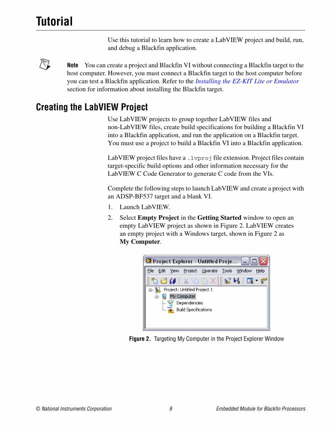
Creating the LabVIEW ProjectUse LabVIEW projects to group together LabVIEW files and non-LabVIEW files, create build specifications for building a Blackfin VI into a Blackfin application, and run the application on a Blackfin target. You must use a project to build a Blackfin VI into a Blackfin application.
LabVIEW project files have a .lvproj file extension. Project files contain target-specific build options and other information necessary for the LabVIEW C Code Generator to generate C code from the VIs.
Complete the following steps to launch LabVIEW and create a project with an ADSP-BF537 target and a blank VI.
1. Launch LabVIEW.
2. Select Empty Project in the Getting Started window to open an empty LabVIEW project as shown in Figure 2. LabVIEW createsan empty project with a Windows target, shown in Figure 2 as My Computer.
Figure 2. Targeting My Computer in the Project Explorer Window
Embedded Module for Blackfin Processors 10 ni.com
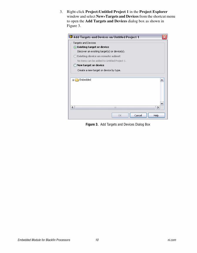
3. Right-click Project:Untitled Project 1 in the Project Explorer window and select New»Targets and Devices from the shortcut menu to open the Add Targets and Devices dialog box as shown in Figure 3.
Figure 3. Add Targets and Devices Dialog Box
© National Instruments Corporation 11 Embedded Module for Blackfin Processors
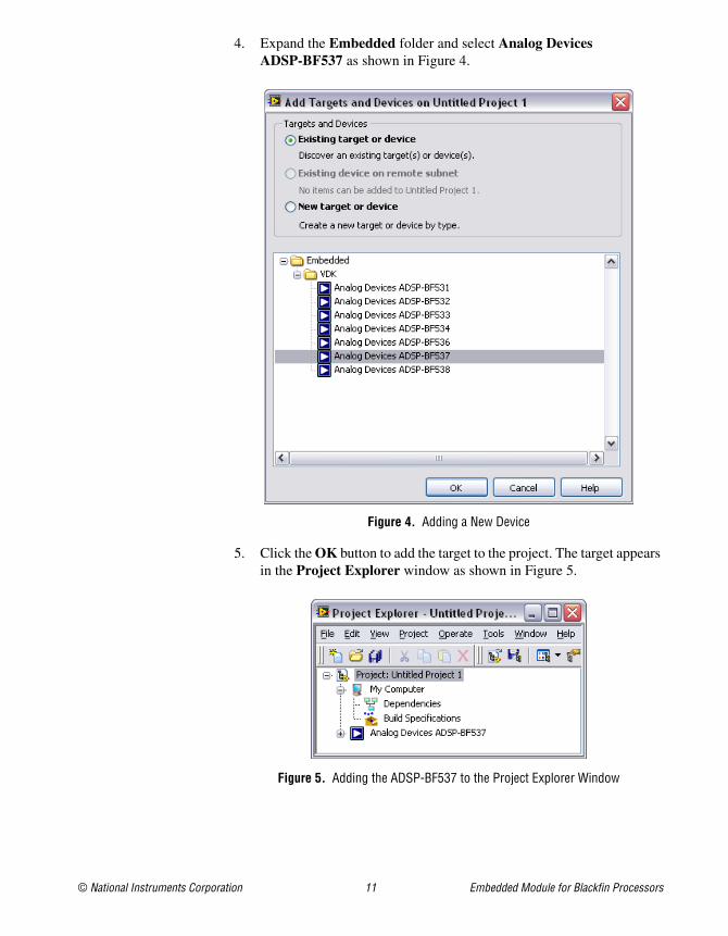
4. Expand the Embedded folder and select Analog Devices ADSP-BF537 as shown in Figure 4.
Figure 4. Adding a New Device
5. Click the OK button to add the target to the project. The target appears in the Project Explorer window as shown in Figure 5.
Figure 5. Adding the ADSP-BF537 to the Project Explorer Window

Embedded Module for Blackfin Processors 12 ni.com
6. Expand the ADSP-BF537 target as shown in Figure 6. LabVIEW automatically adds Dependencies and Build Specifications under the target. SubVIs appear under Dependencies when you add a VI that contains subVIs to a project. Build specifications you create for a target in a project appear under Build Specifications in the Project Explorer window. Refer to the Creating the ADSP-BF537 Build Specification section for information about how to create a build specification.
Figure 6. Expanding the Blackfin Target in the Project Explorer Window
7. Right-click the ADSP-BF537 target and select New»VI from the shortcut menu. The new, untitled VI appears in the Project Explorer window under the ADSP-BF537 target as shown in Figure 7.
Figure 7. Adding a New VI to the Project
The front panel and the block diagram of the new VI open. The front panel, or user interface, appears with a gray background and includes controls and indicators. The block diagram appears with a white background and includes VIs, functions, and structures that control the front panel objects.
© National Instruments Corporation 13 Embedded Module for Blackfin Processors
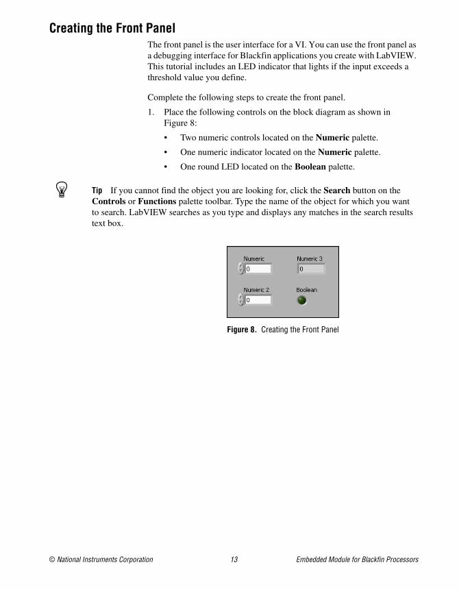
Creating the Front PanelThe front panel is the user interface for a VI. You can use the front panel as a debugging interface for Blackfin applications you create with LabVIEW. This tutorial includes an LED indicator that lights if the input exceeds a threshold value you define.
Complete the following steps to create the front panel.
1. Place the following controls on the block diagram as shown in Figure 8:
• Two numeric controls located on the Numeric palette.
• One numeric indicator located on the Numeric palette.
• One round LED located on the Boolean palette.
Tip If you cannot find the object you are looking for, click the Search button on the Controls or Functions palette toolbar. Type the name of the object for which you wantto search. LabVIEW searches as you type and displays any matches in the search results text box.
Figure 8. Creating the Front Panel
Embedded Module for Blackfin Processors 14 ni.com
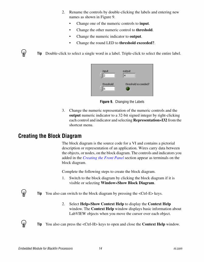
2. Rename the controls by double-clicking the labels and entering new names as shown in Figure 9.
• Change one of the numeric controls to input.
• Change the other numeric control to threshold.
• Change the numeric indicator to output.
• Change the round LED to threshold exceeded?.
Tip Double-click to select a single word in a label. Triple-click to select the entire label.
Figure 9. Changing the Labels
3. Change the numeric representation of the numeric controls and the output numeric indicator to a 32-bit signed integer by right-clicking each control and indicator and selecting Representation»I32 from the shortcut menu.
Creating the Block DiagramThe block diagram is the source code for a VI and contains a pictorial description or representation of an application. Wires carry data between the objects, or nodes, on the block diagram. The controls and indicators you added in the Creating the Front Panel section appear as terminals on the block diagram.
Complete the following steps to create the block diagram.
1. Switch to the block diagram by clicking the block diagram if it is visible or selecting Window»Show Block Diagram.
Tip You also can switch to the block diagram by pressing the <Ctrl-E> keys.
2. Select Help»Show Context Help to display the Context Help window. The Context Help window displays basic information about LabVIEW objects when you move the cursor over each object.
Tip You also can press the <Ctrl-H> keys to open and close the Context Help window.
© National Instruments Corporation 15 Embedded Module for Blackfin Processors
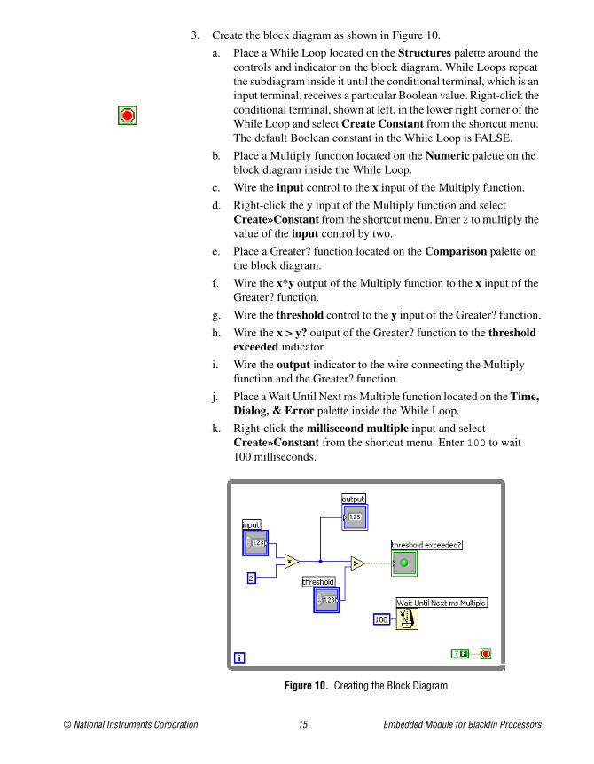
3. Create the block diagram as shown in Figure 10.
a. Place a While Loop located on the Structures palette around the controls and indicator on the block diagram. While Loops repeat the subdiagram inside it until the conditional terminal, which is an input terminal, receives a particular Boolean value. Right-click the conditional terminal, shown at left, in the lower right corner of the While Loop and select Create Constant from the shortcut menu. The default Boolean constant in the While Loop is FALSE.
b. Place a Multiply function located on the Numeric palette on the block diagram inside the While Loop.
c. Wire the input control to the x input of the Multiply function.
d. Right-click the y input of the Multiply function and select Create»Constant from the shortcut menu. Enter 2 to multiply the value of the input control by two.
e. Place a Greater? function located on the Comparison palette on the block diagram.
f. Wire the x*y output of the Multiply function to the x input of the Greater? function.
g. Wire the threshold control to the y input of the Greater? function.
h. Wire the x > y? output of the Greater? function to the threshold exceeded indicator.
i. Wire the output indicator to the wire connecting the Multiply function and the Greater? function.
j. Place a Wait Until Next ms Multiple function located on the Time, Dialog, & Error palette inside the While Loop.
k. Right-click the millisecond multiple input and select Create»Constant from the shortcut menu. Enter 100 to wait 100 milliseconds.
Figure 10. Creating the Block Diagram
Embedded Module for Blackfin Processors 16 ni.com
4. Save the VI as Blackfin Tutorial.
Configuring the Target and Debugging OptionsThe target options you set tell LabVIEW how the Blackfin target is connected to the host computer. The EZ-KIT Lite is connected to the host computer through the USB port, which also is known as a debug agent.
Note You only have to configure the target once unless you change how you connect the target to the host computer.
Complete the following steps to configure the target options.
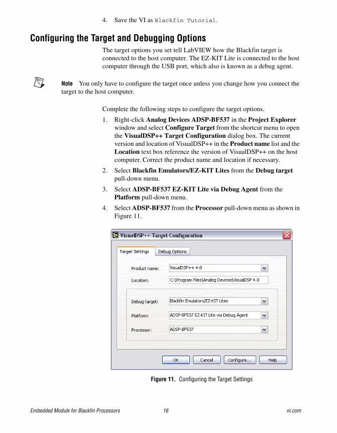
1. Right-click Analog Devices ADSP-BF537 in the Project Explorer window and select Configure Target from the shortcut menu to open the VisualDSP++ Target Configuration dialog box. The current version and location of VisualDSP++ in the Product name list and the Location text box reference the version of VisualDSP++ on the host computer. Correct the product name and location if necessary.
2. Select Blackfin Emulators/EZ-KIT Lites from the Debug target pull-down menu.
3. Select ADSP-BF537 EZ-KIT Lite via Debug Agent from the Platform pull-down menu.
4. Select ADSP-BF537 from the Processor pull-down menu as shown in Figure 11.
Figure 11. Configuring the Target Settings
© National Instruments Corporation 17 Embedded Module for Blackfin Processors
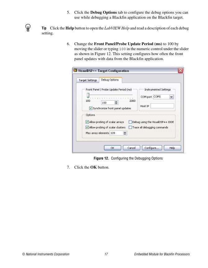
5. Click the Debug Options tab to configure the debug options you can use while debugging a Blackfin application on the Blackfin target.
Tip Click the Help button to open the LabVIEW Help and read a description of each debug setting.
6. Change the Front Panel/Probe Update Period (ms) to 100 by moving the slider or typing 100 in the numeric control under the slider as shown in Figure 12. This setting configures how often the front panel updates with data from the Blackfin application.
Figure 12. Configuring the Debugging Options
7. Click the OK button.
Embedded Module for Blackfin Processors 18 ni.com
Creating the ADSP-BF537 Build SpecificationBuild specifications tell the LabVIEW C Code Generator how to generate the C code and build the Blackfin VI into a Blackfin application. You can create the build specification when you create a project or wait until you are ready to build the Blackfin VI into a Blackfin application.
You can have multiple build specifications for the same target. For example, you might want one build specification that generates debugging information and another build specification that does not generate this extra information.
Complete the following steps to create a build specification.
1. Right-click Build Specifications under the ADSP-BF537 target and select New»VDK Application from the shortcut menu.
2. LabVIEW prompts you to save the project. Click the Save button when prompted and save the project as Blackfin Tutorial. The Build Specification Properties dialog box opens.
3. (Optional) LabVIEW might prompt you to configure the target. Click the Yes button and refer to the Building, Downloading, and Running a Blackfin Application section for information about configuring the target.
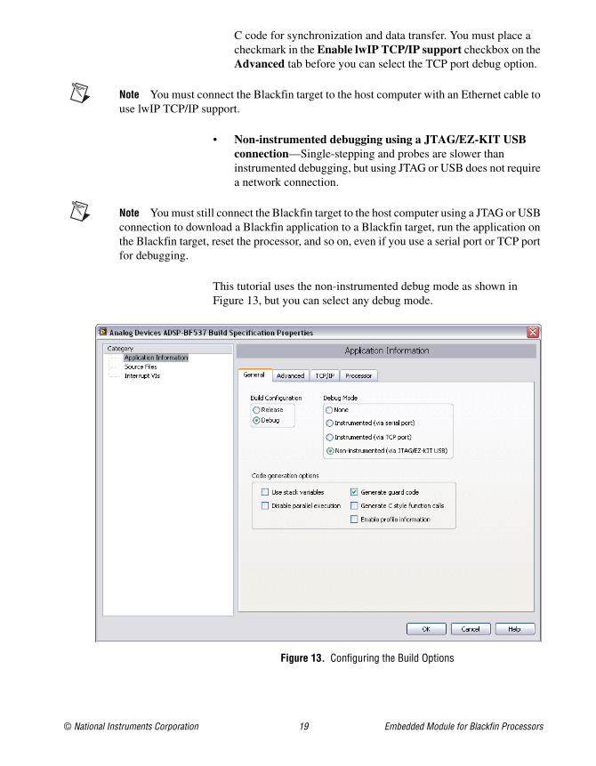
4. Select Debug in the Build Configuration section of the Generaltab. The debug build configuration does not apply any compiler optimizations, which makes the embedded application larger. Use the debug build configuration when you want C source-level debugging.
5. Select an option in the Debug Mode section. You can debug a Blackfin application in the following ways:
• Instrumented debugging using a serial port—Single-stepping and probes are faster than non-instrumented debugging, but using a serial port requires the COM port on the Blackfin target to be connected to the host PC, is intrusive on real-time performance, and uses a larger amount of memory on the Blackfin target. The LabVIEW C Code Generator adds a communication layer to the generated C code for synchronization and data transfer. You must remove the checkmark from the Redirect stdout to serial port checkbox on the Advanced tab before you can select the serial port debug option.
• Instrumented debugging using a TCP port—Single-stepping and probes are faster than non-instrumented debugging, but using a TCP port requires that the Blackfin target is connected to an Ethernet port, is intrusive on real-time performance, and uses a larger amount of memory on the Blackfin target. The LabVIEW C Code Generator adds a communication layer to the generated
© National Instruments Corporation 19 Embedded Module for Blackfin Processors
C code for synchronization and data transfer. You must place a checkmark in the Enable lwIP TCP/IP support checkbox on the Advanced tab before you can select the TCP port debug option.
Note You must connect the Blackfin target to the host computer with an Ethernet cable to use lwIP TCP/IP support.
• Non-instrumented debugging using a JTAG/EZ-KIT USB connection—Single-stepping and probes are slower than instrumented debugging, but using JTAG or USB does not require a network connection.
Note You must still connect the Blackfin target to the host computer using a JTAG or USB connection to download a Blackfin application to a Blackfin target, run the application on the Blackfin target, reset the processor, and so on, even if you use a serial port or TCP port for debugging.
This tutorial uses the non-instrumented debug mode as shown in Figure 13, but you can select any debug mode.
Figure 13. Configuring the Build Options
Embedded Module for Blackfin Processors 20 ni.com
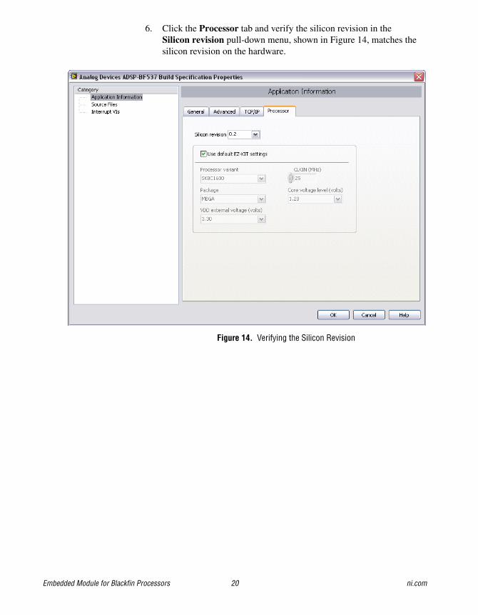
6. Click the Processor tab and verify the silicon revision in the Silicon revision pull-down menu, shown in Figure 14, matches the silicon revision on the hardware.
Figure 14. Verifying the Silicon Revision
© National Instruments Corporation 21 Embedded Module for Blackfin Processors
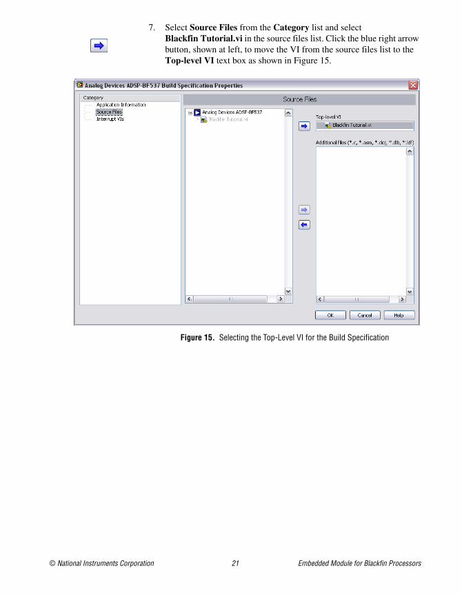
7. Select Source Files from the Category list and select Blackfin Tutorial.vi in the source files list. Click the blue right arrow button, shown at left, to move the VI from the source files list to the Top-level VI text box as shown in Figure 15.
Figure 15. Selecting the Top-Level VI for the Build Specification
Embedded Module for Blackfin Processors 22 ni.com
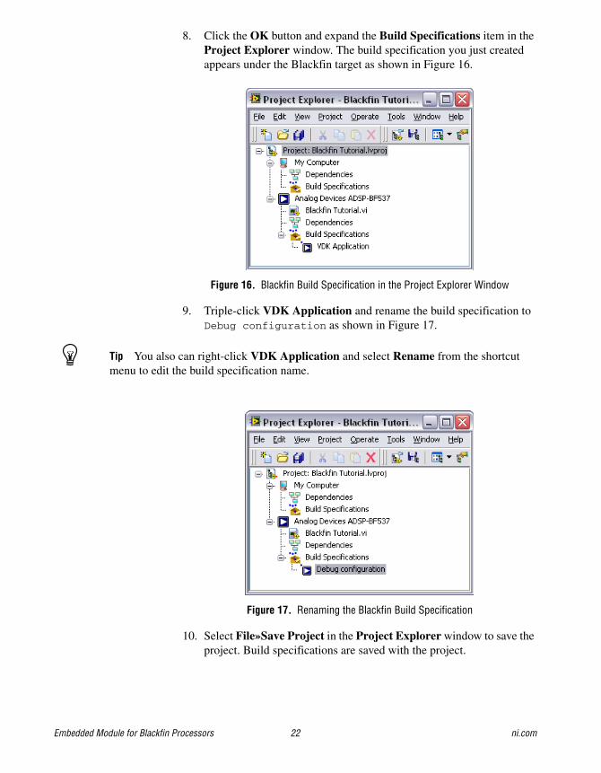
8. Click the OK button and expand the Build Specifications item in the Project Explorer window. The build specification you just created appears under the Blackfin target as shown in Figure 16.
Figure 16. Blackfin Build Specification in the Project Explorer Window
9. Triple-click VDK Application and rename the build specification to Debug configuration as shown in Figure 17.
Tip You also can right-click VDK Application and select Rename from the shortcut menu to edit the build specification name.
Figure 17. Renaming the Blackfin Build Specification
10. Select File»Save Project in the Project Explorer window to save the project. Build specifications are saved with the project.

© National Instruments Corporation 23 Embedded Module for Blackfin Processors
Building, Downloading, and Running a Blackfin ApplicationAfter you develop the Blackfin VI on the host computer, you build the Blackfin VI into a Blackfin application you can run on a Blackfin target. When you build a Blackfin application, the LabVIEW C Code Generator generates C code from the LabVIEW block diagram using the settings you configure.
Note Before you can build, or compile, a Blackfin VI into a Blackfin application, you must configure the build specifications, the target settings, and the debug settings. Referto the Creating the ADSP-BF537 Build Specification and Configuring the Target and Debugging Options sections for information about configuring specifications and settings.
1. Right-click Debug configuration in the Project Explorer window and select Build from the shortcut menu to build the Blackfin VI into a Blackfin application. LabVIEW displays the status of the building and linking process.
2. Right-click Debug configuration again and select Debug from the shortcut menu to deploy the application to the Blackfin target. The application automatically runs on the Blackfin target when you select Debug from the shortcut menu.
3. Enter a value in the threshold front panel numeric control of the Blackfin Tutorial VI on the host computer.
4. Enter different values in the input numeric control. In Figure 18, the front panel on the left does not exceed the threshold value. If you enter a number greater than the threshold, the threshold exceeded? LED lights as shown in the front panel on the right in Figure 18.
Figure 18. Increasing Input Causes Output to Exceed Threshold and Lights the LED
5. Click the Abort Execution button, shown at left, to stop the Blackfin application.
Embedded Module for Blackfin Processors 24 ni.com
Debugging with Breakpoints and ProbesComplete the following steps to debug the Blackfin tutorial application with breakpoints and probes.
1. Switch to the block diagram if it is not visible.
2. Right-click the Multiply function and select Set Breakpoint fromthe shortcut menu. The breakpoint is highlighted with a red border around the function. When you run the Blackfin application, execution pauses just before the function executes. If you are using JTAG or USB/EZ-KIT for debugging, LabVIEW might prompt you to halt the processor.
3. Right-click Debug configuration in the Project Explorer window and select Debug from the shortcut menu. LabVIEW prompts you to save changes to the VI. LabVIEW also prompts you if you need to rebuild or redownload the Blackfin application to the Blackfin target.
Tip LabVIEW uses default values for controls and indicators when building a Blackfin VI into a Blackfin application. To change the initial values, enter the new values in the front panel controls and then select Edit»Make Current Values Default to change the initial values. You must rebuild the Blackfin application after you change the initial values of the controls.
The Blackfin tutorial application begins running on the Blackfin target. When you reach a breakpoint during execution, the Blackfin target halts all operation, the application pauses, and the Pause button, shown at left, appears red and changes to a Continue button.
© National Instruments Corporation 25 Embedded Module for Blackfin Processors
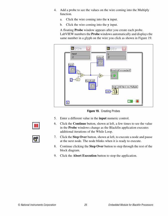
4. Add a probe to see the values on the wire coming into the Multiply function.
a. Click the wire coming into the x input.
b. Click the wire coming into the y input.
A floating Probe window appears after you create each probe. LabVIEW numbers the Probe windows automatically and displays the same number in a glyph on the wire you click as shown in Figure 19.
Figure 19. Creating Probes
5. Enter a different value in the input numeric control.
6. Click the Continue button, shown at left, a few times to see the value in the Probe windows change as the Blackfin application executes additional iterations of the While Loop.
7. Click the Step Over button, shown at left, to execute a node and pause at the next node. The node blinks when it is ready to execute.
8. Continue clicking the Step Over button to step through the rest of the block diagram.
9. Click the Abort Execution button to stop the application.
National Instruments, NI, ni.com, and LabVIEW are trademarks of National Instruments Corporation. Refer to the Terms of Use section on ni.com/legal for more information about National Instruments trademarks. Other product and company names mentioned herein are trademarks or trade names of their respective companies. For patents covering National Instruments products, refer to the appropriate location: Help»Patents in your software, the patents.txt file on your CD, or ni.com/patents.
© 2006–2007 National Instruments Corporation. All rights reserved. 371656B-01 Feb 07
Where to Go from HereNational Instruments provides many resources to help you succeed with your NI products. Use the following documentation resources as you start exploring LabVIEW and the Embedded Module for Blackfin Processors.
• LabVIEW Help, available by selecting Help»Search the LabVIEW Help in LabVIEW, provides information about LabVIEW programming, step-by-step instructions for using LabVIEW, and reference information about LabVIEW VIs, functions, palettes, menus, and tools. Refer to the Embedded Module for Blackfin Processors book on the Contents tab of the LabVIEW Help for information specific to the Embedded Module for Blackfin Processors and Blackfin applications.
• Context help provides brief descriptions of VIs and functions with a link to the complete reference for a VI or function. Select Help»Show Context Help to open the Context Help window.
• Examples are available in the labview\examples\lvemb\Blackfin directory and can help you get started creating Blackfin VIs.
• The readme file, available by selecting Start»All Programs»National Instruments»LabVIEW»Readme and opening readme_BLACKFIN.html, contains known issues and last-minute information.
• The Getting Started with ADSP-BF537 EZ-KIT Lite manual, available in the EZ-KIT box, familiarizes you with the hardware capabilities of the EZ-KIT.
• The ADSP-BF537 EZ-KIT Lite Evaluation System Manual, available in the EZ-KIT box, describes the operation and configuration of the board components and provides a schematic for reference.
• The DAQ Adapter User Guide describes how to install the National Instruments DAQ Adaptor and provides pinout information. The NI DAQ Adaptor comes in the EZ-KIT box.