Embed Size (px)
Citation preview
Development GuidelinesLabVIEW Development Guidelines
July 2000 EditionPart Number 321393C-01
Worldwide Technical Support and Product Information
www.ni.com
National Instruments Corporate Headquarters
11500 North Mopac Expressway Austin, Texas 78759-3504 USA Tel: 512 794 0100
Worldwide Offices
Australia 03 9879 5166, Austria 0662 45 79 90 0, Belgium 02 757 00 20, Brazil 011 284 5011,Canada (Calgary) 403 274 9391, Canada (Ontario) 905 785 0085, Canada (Québec) 514 694 8521,China 0755 3904939, Denmark 45 76 26 00, Finland 09 725 725 11, France 01 48 14 24 24,Germany 089 741 31 30, Greece 30 1 42 96 427, Hong Kong 2645 3186, India 91805275406,Israel 03 6120092, Italy 02 413091, Japan 03 5472 2970, Korea 02 596 7456, Mexico (D.F.) 5 280 7625,Mexico (Monterrey) 8 357 7695, Netherlands 0348 433466, New Zealand 09 914 0488, Norway 32 27 73 00,Poland 0 22 528 94 06, Portugal 351 1 726 9011, Singapore 2265886, Spain 91 640 0085,Sweden 08 587 895 00, Switzerland 056 200 51 51, Taiwan 02 2528 7227, United Kingdom 01635 523545
For further support information, see the Technical Support Resources appendix. To comment on thedocumentation, send e-mail to [email protected]
© Copyright 1997, 2000 National Instruments Corporation. All rights reserved.
Important Information
WarrantyThe media on which you receive National Instruments software are warranted not to fail to execute programming instructions,due to defects in materials and workmanship, for a period of 90 days from date of shipment, as evidenced by receipts or otherdocumentation. National Instruments will, at its option, repair or replace software media that do not execute programminginstructions if National Instruments receives notice of such defects during the warranty period. National Instruments does notwarrant that the operation of the software shall be uninterrupted or error free.
A Return Material Authorization (RMA) number must be obtained from the factory and clearly marked on the outside ofthe package before any equipment will be accepted for warranty work. National Instruments will pay the shipping costs ofreturning to the owner parts which are covered by warranty.
National Instruments believes that the information in this document is accurate. The document has been carefully reviewedfor technical accuracy. In the event that technical or typographical errors exist, National Instruments reserves the right tomake changes to subsequent editions of this document without prior notice to holders of this edition. The reader should consultNational Instruments if errors are suspected. In no event shall National Instruments be liable for any damages arising out ofor related to this document or the information contained in it.
EXCEPT AS SPECIFIED HEREIN, NATIONAL INSTRUMENTS MAKES NO WARRANTIES, EXPRESS OR IMPLIED, AND SPECIFICALLY DISCLAIMS ANY
WARRANTY OF MERCHANTABILITY OR FITNESS FOR A PARTICULAR PURPOSE. CUSTOMER’S RIGHT TO RECOVER DAMAGES CAUSED BY FAULT OR
NEGLIGENCE ON THE PART OF NATIONAL INSTRUMENTS SHALL BE LIMITED TO THE AMOUNT THERETOFORE PAID BY THE CUSTOMER. NATIONAL
INSTRUMENTS WILL NOT BE LIABLE FOR DAMAGES RESULTING FROM LOSS OF DATA, PROFITS, USE OF PRODUCTS, OR INCIDENTAL OR
CONSEQUENTIAL DAMAGES, EVEN IF ADVISED OF THE POSSIBILITY THEREOF. This limitation of the liability of National Instruments willapply regardless of the form of action, whether in contract or tort, including negligence. Any action against National Instrumentsmust be brought within one year after the cause of action accrues. National Instruments shall not be liable for any delay inperformance due to causes beyond its reasonable control. The warranty provided herein does not cover damages, defects,malfunctions, or service failures caused by owner’s failure to follow the National Instruments installation, operation, ormaintenance instructions; owner’s modification of the product; owner’s abuse, misuse, or negligent acts; and power failure orsurges, fire, flood, accident, actions of third parties, or other events outside reasonable control.
CopyrightUnder the copyright laws, this publication may not be reproduced or transmitted in any form, electronic or mechanical, includingphotocopying, recording, storing in an information retrieval system, or translating, in whole or in part, without the prior writtenconsent of National Instruments Corporation.
TrademarksLabVIEW™, National Instruments™, and ni.com™ are trademarks of National Instruments Corporation.
Product and company names mentioned herein are trademarks or trade names of their respective companies.
WARNING REGARDING USE OF NATIONAL INSTRUMENTS PRODUCTS(1) NATIONAL INSTRUMENTS PRODUCTS ARE NOT DESIGNED WITH COMPONENTS AND TESTING FOR A LEVELOF RELIABILITY SUITABLE FOR USE IN OR IN CONNECTION WITH SURGICAL IMPLANTS OR AS CRITICALCOMPONENTS IN ANY LIFE SUPPORT SYSTEMS WHOSE FAILURE TO PERFORM CAN REASONABLY BEEXPECTED TO CAUSE SIGNIFICANT INJURY TO A HUMAN.
(2) IN ANY APPLICATION, INCLUDING THE ABOVE, RELIABILITY OF OPERATION OF THE SOFTWARE PRODUCTSCAN BE IMPAIRED BY ADVERSE FACTORS, INCLUDING BUT NOT LIMITED TO FLUCTUATIONS IN ELECTRICALPOWER SUPPLY, COMPUTER HARDWARE MALFUNCTIONS, COMPUTER OPERATING SYSTEM SOFTWAREFITNESS, FITNESS OF COMPILERS AND DEVELOPMENT SOFTWARE USED TO DEVELOP AN APPLICATION,INSTALLATION ERRORS, SOFTWARE AND HARDWARE COMPATIBILITY PROBLEMS, MALFUNCTIONS ORFAILURES OF ELECTRONIC MONITORING OR CONTROL DEVICES, TRANSIENT FAILURES OF ELECTRONICSYSTEMS (HARDWARE AND/OR SOFTWARE), UNANTICIPATED USES OR MISUSES, OR ERRORS ON THE PART OFTHE USER OR APPLICATIONS DESIGNER (ADVERSE FACTORS SUCH AS THESE ARE HEREAFTERCOLLECTIVELY TERMED “SYSTEM FAILURES”). ANY APPLICATION WHERE A SYSTEM FAILURE WOULDCREATE A RISK OF HARM TO PROPERTY OR PERSONS (INCLUDING THE RISK OF BODILY INJURY AND DEATH)SHOULD NOT BE RELIANT SOLELY UPON ONE FORM OF ELECTRONIC SYSTEM DUE TO THE RISK OF SYSTEMFAILURE. TO AVOID DAMAGE, INJURY, OR DEATH, THE USER OR APPLICATION DESIGNER MUST TAKEREASONABLY PRUDENT STEPS TO PROTECT AGAINST SYSTEM FAILURES, INCLUDING BUT NOT LIMITED TOBACK-UP OR SHUT DOWN MECHANISMS. BECAUSE EACH END-USER SYSTEM IS CUSTOMIZED AND DIFFERSFROM NATIONAL INSTRUMENTS' TESTING PLATFORMS AND BECAUSE A USER OR APPLICATION DESIGNERMAY USE NATIONAL INSTRUMENTS PRODUCTS IN COMBINATION WITH OTHER PRODUCTS IN A MANNER NOTEVALUATED OR CONTEMPLATED BY NATIONAL INSTRUMENTS, THE USER OR APPLICATION DESIGNER ISULTIMATELY RESPONSIBLE FOR VERIFYING AND VALIDATING THE SUITABILITY OF NATIONALINSTRUMENTS PRODUCTS WHENEVER NATIONAL INSTRUMENTS PRODUCTS ARE INCORPORATED IN ASYSTEM OR APPLICATION, INCLUDING, WITHOUT LIMITATION, THE APPROPRIATE DESIGN, PROCESS ANDSAFETY LEVEL OF SUCH SYSTEM OR APPLICATION.
© National Instruments Corporation v LabVIEW Development Guidelines
Contents
About This ManualConventions ................................................................................................................... ixRelated Documentation..................................................................................................x
Chapter 1Development Models
Common Development Pitfalls......................................................................................1-1Lifecycle Models ...........................................................................................................1-4
Code and Fix Model ........................................................................................1-4Waterfall Model...............................................................................................1-5Modified Waterfall Model...............................................................................1-7Prototyping ......................................................................................................1-7
LabVIEW Prototyping Methods .......................................................1-8Spiral Model ....................................................................................................1-9
Summary........................................................................................................................1-11
Chapter 2Incorporating Quality into the Development Process
Quality Requirements ....................................................................................................2-1Configuration Management ...........................................................................................2-2
Source Code Control .......................................................................................2-2Managing Project-Related Files ......................................................................2-3Retrieving Old Versions of Files.....................................................................2-3Tracking Changes............................................................................................2-4Change Control................................................................................................2-4
Testing Guidelines .........................................................................................................2-5Black Box and White Box Testing..................................................................2-6Unit, Integration, and System Testing.............................................................2-6
Unit Testing.......................................................................................2-6Integration Testing ............................................................................2-8System Testing..................................................................................2-9
Formal Methods of Verification......................................................................2-9Style Guidelines .............................................................................................................2-10Design Reviews .............................................................................................................2-11Code Walkthroughs .......................................................................................................2-11Postmortem Evaluation..................................................................................................2-12
Contents
LabVIEW Development Guidelines vi www.ni.com
Software Quality Standards........................................................................................... 2-13International Organization for Standardization ISO 9000 .............................. 2-13U.S. Food and Drug Administration Standards .............................................. 2-14Capability Maturity Model (CMM) ................................................................ 2-14Institute of Electrical and Electronic Engineers (IEEE) Standards................. 2-16
Chapter 3Prototyping and Design Techniques
Clearly Define the Requirements of the Application .................................................... 3-1Top-Down Design ......................................................................................................... 3-2
Data Acquisition System Example ................................................................. 3-3Bottom-Up Design......................................................................................................... 3-6
Instrument Driver Example............................................................................. 3-7Designing for Multiple Developers ............................................................................... 3-8Front Panel Prototyping................................................................................................. 3-9Performance Benchmarking .......................................................................................... 3-10Identify Common Operations ........................................................................................ 3-11
Chapter 4Scheduling and Project Tracking
Estimation...................................................................................................................... 4-1Source Lines of Code/Number of Nodes Estimation...................................... 4-2
Problems with Source Lines of Code and Number of Nodes........... 4-3Effort Estimation............................................................................................. 4-4Wideband Delphi Estimation .......................................................................... 4-4Other Estimation Techniques.......................................................................... 4-5
Mapping Estimates to Schedules................................................................................... 4-6Tracking Schedules Using Milestones .......................................................................... 4-7
Responding to Missed Milestones .................................................................. 4-7
Chapter 5Creating Documentation
Design and Development Documentation..................................................................... 5-2Developing User Documentation .................................................................................. 5-2
Documentation for a Library of VIs ............................................................... 5-2Documentation for an Application.................................................................. 5-3
Creating Help Files........................................................................................................ 5-3VI and Control Descriptions.......................................................................................... 5-4
VI Description................................................................................................. 5-4Self-Documenting Front Panels ...................................................................... 5-4Control and Indicator Descriptions ................................................................. 5-5
Contents
© National Instruments Corporation vii LabVIEW Development Guidelines
Chapter 6LabVIEW Style Guide
Organization...................................................................................................................6-1Front Panel Style............................................................................................................6-3
Fonts and Text Styles ......................................................................................6-3Color ................................................................................................................6-3Graphics and Custom Controls........................................................................6-4Layout..............................................................................................................6-5Sizing and Positioning.....................................................................................6-5Labels ..............................................................................................................6-6Enums versus Rings ........................................................................................6-6Default Values and Ranges .............................................................................6-7Property Nodes ................................................................................................6-7Key Navigation................................................................................................6-8Dialog Boxes ...................................................................................................6-8
Block Diagram Style......................................................................................................6-9Good Wiring Techniques ................................................................................6-9Memory and Speed Optimization....................................................................6-9Sizing and Positioning.....................................................................................6-11
Left-to-Right Layouts .......................................................................6-11Block Diagram Comments ..............................................................................6-11
Icon and Connector Style...............................................................................................6-12Icon ..................................................................................................................6-13Connector ........................................................................................................6-14
Style Checklist ...............................................................................................................6-14VI Checklist.....................................................................................................6-14Front Panel Checklist ......................................................................................6-16Block Diagram Checklist ................................................................................6-17
Appendix AReferences
Appendix BTechnical Support Resources
Glossary
Index
Contents
LabVIEW Development Guidelines viii www.ni.com
FiguresFigure 1-1. Waterfall Lifecycle Model .................................................................... 1-5Figure 1-2. Spiral Lifecycle Model ......................................................................... 1-9
Figure 2-1. Capability Maturity Model ................................................................... 2-15
Figure 3-1. Flowchart of a Data Acquisition System .............................................. 3-4Figure 3-2. Mapping Pseudocode into a LabVIEW Data Structure ........................ 3-5Figure 3-3. Mapping Pseudocode into Actual LabVIEW Code .............................. 3-5Figure 3-4. Data Flow for a Generic Data Acquisition Program............................. 3-6Figure 3-5. VI Hierarchy for the Tektronix 370A ................................................... 3-8Figure 3-6. Operations Run Independently ............................................................. 3-11Figure 3-7. Loop Performs Operation Three Times ................................................ 3-11
Figure 6-1. Directory Hierarchy .............................................................................. 6-2Figure 6-2. Example of Imported Graphics Used in a Pict Ring............................. 6-4Figure 6-3. Example of Using Decorations to Visually Group Objects Together... 6-5Figure 6-4. Free Labels on a Boolean Control ........................................................ 6-6Figure 6-5. While Loop with 50 Second Delay ....................................................... 6-10Figure 6-6. Example: Queue VIs ............................................................................. 6-13
TableTable 1-1. Risk Exposure Analysis Example ......................................................... 1-10
© National Instruments Corporation ix LabVIEW Development Guidelines
About This Manual
The LabVIEW Development Guidelines describe many of the issues thatarise when developing large applications. The guidelines are based on theadvice of LabVIEW developers, and provide a basic survey of softwareengineering techniques you might find useful when developing yourown projects.
There is also a discussion of style for creating VIs. Developers who haveused LabVIEW and are comfortable in the LabVIEW environment can usethe LabVIEW Development Guidelines to maintain a consistent andeffective style in their projects.
ConventionsThe following conventions appear in this manual:
» The » symbol leads you through nested menu items and dialog box optionsto a final action. The sequence File»Page Setup»Options directs you topull down the File menu, select the Page Setup item, and select Optionsfrom the last dialog box.
This icon denotes a tip, which alerts you to advisory information.
bold Bold text denotes items that you must select or click on in the software,such as menu items and dialog box options. Bold text also denotesparameter names.
italic Italic text denotes variables, emphasis, a cross reference, or an introductionto a key concept. This font also denotes text that is a placeholder for a wordor value that you must supply.
monospace Text in this font denotes text or characters that you should enter from thekeyboard, sections of code, programming examples, and syntax examples.This font is also used for the proper names of disk drives, paths, directories,programs, subprograms, subroutines, device names, functions, operations,variables, filenames and extensions, and code excerpts.
Platform Text in this font denotes a specific platform and indicates that the textfollowing it applies only to that platform.

About This Manual
LabVIEW Development Guidelines x www.ni.com
Related DocumentationThe following documents contain information that you might find helpfulas you read this manual:
• LabVIEW Help, available by selecting Help»Contents and Index.
© National Instruments Corporation 1-1 LabVIEW Development Guidelines
1Development Models
This chapter provides examples of some common development pitfalls anddescribes a number of software engineering lifecycle models.
LabVIEW makes it easy to assemble components of data acquisition, test,and control systems. Because it is so easy to program in LabVIEW, youmight be tempted to begin developing VIs immediately with relatively littleplanning. For simple applications, such as quick lab tests or monitoringapplications, this approach might be appropriate. However, for largerdevelopment projects, good planning becomes vital.
Common Development PitfallsIf you have developed large applications before, you probably have heardsome of the following statements. Most of these approaches start out withgood intentions and seem quite reasonable. However, these approaches areoften unrealistic and can lead to delays, quality problems, and poor moraleamong team members.
• “I haven’t really thought it through, but I’d guess that the project youare requesting can be completed in…”
Off-the-cuff estimates rarely are correct because they usually are basedon an incomplete understanding of the problem. When developing forsomeone else, you might each have different ideas about requirements.To estimate accurately, you both must clearly understand therequirements and work through at least a preliminary high-level designso you understand the components you need to develop.
• “I think I understand the problem the customer wants to solve, so I’mready to dive into development.”
There are two problems with this statement. First, lack of consensus onproject goals results in schedule delays. Your idea of what a customerwants might be based on inadequate communication. Developing arequirements document and prototyping a system, both described inthe Lifecycle Models section later in this chapter, can be useful tools toclarify goals. A second problem with this statement is that diving intodevelopment might mean writing code without a detailed design. Justas builders do not construct a building without architectural plans,
Chapter 1 Development Models
LabVIEW Development Guidelines 1-2 www.ni.com
developers should not begin building an application without a detaileddesign. Refer to the Code and Fix Model section later in this chapterfor more information about development models to follow.
• “We don’t have time to write detailed plans. We’re under a tightschedule, so we need to start developing right away.”
This situation is similar to the previous example but is such a commonmistake that it is worth emphasizing. Software developers frequentlyskip important planning because it does not seem as productive asdeveloping code. As a result, you develop VIs without a clear idea ofhow they all fit together, and you might have to rework sections as youdiscover mistakes. Taking the time to develop a plan can prevent costlyrework at the development stage. Refer to the Lifecycle Models sectionlater in this chapter and Chapter 3, Prototyping and DesignTechniques, for better approaches to developing software.
• “Let’s try for the whole ball of wax in the first release. If it doesn’t doeverything, it won’t be useful.”
In some cases, this might be correct. However, in most applications,developing in stages is a better approach. When you analyze therequirements for a project, prioritize features. You might be able todevelop an initial VI that provides useful functionality in a shorter timeat a lower cost. Then, you can add features incrementally. The moreyou try to accomplish in a single stage, the greater the risk of fallingbehind schedule. Releasing software incrementally reduces schedulepressures and ensures timely software release. Refer to the LifecycleModels section later in this chapter for more information about usingdevelopment models.
• “If I can just get all the features in within the next month, I should beable to fix any problems before the software is released.”
To release high-quality products on time, maintain quality standardsthroughout development. Do not build new features on an unstablefoundation and rely on correcting problems later. This exacerbatesproblems and increases cost. Although you might complete all thefeatures on time, the time required to correct the problems in theexisting and the new code can delay the release of the product.Prioritize features and implement the most important ones first. Oncethe most important features are tested thoroughly, you can choose towork on lower priority features or defer them to a future release. Referto Chapter 2, Incorporating Quality into the Development Process, formore information about techniques for producing high-qualitysoftware.
Chapter 1 Development Models
© National Instruments Corporation 1-3 LabVIEW Development Guidelines
• “We’re behind in our project. Let’s throw more developers onto theproblem.”
In many cases, doing this actually can delay the project. Addingdevelopers to a project requires time for training, which can take awaytime originally scheduled for development. Add resources earlier inthe project rather than later. Also, there is a limit to the number ofpeople who can work on a project effectively. With a few people, thereis less overlap. You can partition the project so each person works ona particular section. The more people you add, the more difficult itbecomes to avoid overlap. Chapter 3, Prototyping and DesignTechniques, describes methods for partitioning software for multipledevelopers. Chapter 2, Incorporating Quality into the DevelopmentProcess, describes configuration management techniques that can helpminimize overlap.
• “We’re behind in our project, but we still think we can get all thefeatures in by the specified date.”
When you are behind in a project, it is important to recognize that factand deal with it. Assuming you can make up lost time can postponechoices until it becomes costly to deal with them. For example, ifyou realize in the first month of a six-month project that you arebehind, you might sacrifice planned features or add time to theoverall schedule. If you do not realize you are behind schedule untilthe fifth month, other groups might have made decisions that arecostly to change.
When you realize you are behind, adjust the schedule or considerfeatures you can drop or postpone to subsequent releases. Do notignore the delay or sacrifice testing scheduled for later in the process.
Numerous other problems can arise when developing software. Thefollowing list includes some of the fundamental elements of developingquality software on time:
• Spend sufficient time planning.
• Make sure the whole team thoroughly understands the problems thatmust be solved.
• Have a flexible development strategy that minimizes risk andaccommodates changes.
Chapter 1 Development Models
LabVIEW Development Guidelines 1-4 www.ni.com
Lifecycle ModelsSoftware development projects are complex. To deal with thesecomplexities, developers have collected a core set of developmentprinciples. These principles define the field of software engineering.A major component of this field is the lifecycle model. The lifecycle modeldescribes the steps you follow to develop software—from the initialconcept stage to the release, maintenance, and subsequent upgrading of thesoftware.
Currently, there are many different lifecycle models. Each has advantagesand disadvantages in terms of time-to-release, quality, and riskmanagement. This section describes some of the most common modelsused in software engineering. Many hybrids of these models exist, so usethe parts you believe will work for your project.
Although this section is theoretical in its discussion, in practice consider allthe steps these models encompass. Consider when and how you decide thatthe requirements and specifications are complete and how you deal withchanges to them. The lifecycle model serves as a foundation for the entiredevelopment process. Good choices in this area can improve the quality ofthe software you develop and decrease the time it takes to develop it.
Code and Fix ModelThe code and fix model probably is the most frequently used developmentmethodology in software engineering. It starts with little or no initialplanning. You immediately start developing, fixing problems as you findthem, until the project is complete.
Code and fix is a tempting choice when you are faced with a tightdevelopment schedule because you begin developing code right away andsee immediate results.
Unfortunately, if you find major architectural problems late in the process,you might have to rewrite large parts of the application. Alternativedevelopment models can help you catch these problems in the early conceptstages when it is easier and much less expensive to make changes.
The code and fix model is appropriate only for small projects that are notintended to serve as the basis for future development.
Chapter 1 Development Models
© National Instruments Corporation 1-5 LabVIEW Development Guidelines
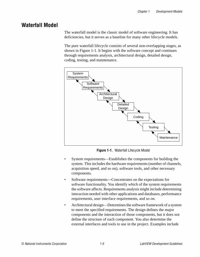
Waterfall ModelThe waterfall model is the classic model of software engineering. It hasdeficiencies, but it serves as a baseline for many other lifecycle models.
The pure waterfall lifecycle consists of several non-overlapping stages, asshown in Figure 1-1. It begins with the software concept and continuesthrough requirements analysis, architectural design, detailed design,coding, testing, and maintenance.
Figure 1-1. Waterfall Lifecycle Model
• System requirements—Establishes the components for building thesystem. This includes the hardware requirements (number of channels,acquisition speed, and so on), software tools, and other necessarycomponents.
• Software requirements—Concentrates on the expectations forsoftware functionality. You identify which of the system requirementsthe software affects. Requirements analysis might include determininginteraction needed with other applications and databases, performancerequirements, user interface requirements, and so on.
• Architectural design—Determines the software framework of a systemto meet the specified requirements. The design defines the majorcomponents and the interaction of those components, but it does notdefine the structure of each component. You also determine theexternal interfaces and tools to use in the project. Examples include
SystemRequirements
SoftwareRequirements
ArchitecturalDesign
DetailedDesign
Coding
Testing
Maintenance
Chapter 1 Development Models
LabVIEW Development Guidelines 1-6 www.ni.com
decisions on hardware, such as plug-in boards, and external pieces ofsoftware, such as databases or other libraries.
• Detailed design—Examines the software components defined in thearchitectural design stage and produces a specification for how eachcomponent is implemented.
• Coding—Implements the detailed design specification.
• Testing—Determines whether the software meets the specifiedrequirements and finds any errors present in the code.
• Maintenance—Perform as needed to deal with problems andenhancement requests after the software is released.
In some organizations, each change is reviewed by a change controlboard to ensure that quality is maintained. You also can apply the fullwaterfall development cycle model when you implement these changerequests.
In each stage, you create documents that explain your objectives anddescribe the requirements for that phase. At the end of each stage, you holda review to determine whether the project can proceed to the next stage.Also, you can incorporate prototyping into any stage from the architecturaldesign and after. Refer to the Prototyping section later in this chapter formore information about using prototyping in projects.
The waterfall lifecycle model is one of the oldest models and is widely usedin government projects and in many major companies. Because itemphasizes planning in the early stages, it helps catch design flaws beforethey are developed. Also, because it is document and planning intensive, itworks well for projects in which quality control is a major concern.
Many people believe you should not apply this model to all situations. Forexample, with the pure waterfall model, you must state the requirementsbefore you begin the design, and you must state the complete design beforeyou begin coding. There is no overlap between stages. In real-worlddevelopment, however, you might discover issues during the design orcoding stages that point out errors or gaps in the requirements.
The waterfall method does not prohibit returning to an earlier phase, forexample, from the design phase to the requirements phase. However, thisinvolves costly rework. Each completed phase requires formal review andextensive documentation development. Thus, oversights made in therequirements phase are expensive to correct later.
Chapter 1 Development Models
© National Instruments Corporation 1-7 LabVIEW Development Guidelines
Because the actual development comes late in the process, you do not seeresults for a long time. This can be disconcerting to management and tocustomers. Many people also think the amount of documentation isexcessive and inflexible.
Although the waterfall model has its weaknesses, it is instructive because itemphasizes important stages of project development. Even if you do notapply this model, consider each of these stages and its relationship to yourown project.
Modified Waterfall ModelMany engineers recommend modified versions of the waterfall lifecycle.These modifications tend to focus on allowing some of the stages tooverlap, reducing the documentation requirements, and reducing the cost ofreturning to earlier stages to revise them. Another common modification isto incorporate prototyping into the requirements phases, as described in thefollowing section.
Overlapping stages such as requirements and design make it possible tofeed information from the design phase back into the requirements.However, this can make it more difficult to know when you are finishedwith a given stage. Consequently, it is more difficult to track progress.Without distinct stages, problems might cause you to defer importantdecisions until late in the process when they are more expensive to correct.
PrototypingOne of the main problems with the waterfall model is that the requirementsoften are not completely understood in the early development stages. Whenyou reach the design or coding stages, you begin to see how everythingworks together, and you might discover you need to adjust requirements.
Prototyping can be an effective tool for demonstrating how a design mightdeal with a set of requirements. You can build a prototype, adjust therequirements, and revise the prototype several times until you have a clearpicture of your overall objectives. In addition to clarifying therequirements, the prototype also defines many areas of the designsimultaneously.
The pure waterfall model allows for prototyping in the later architecturaldesign stage and subsequent stages but not in the early requirements stages.

Chapter 1 Development Models
LabVIEW Development Guidelines 1-8 www.ni.com
Prototyping has drawbacks, however. Because it appears that you have aworking system quickly, customers might expect a complete system soonerthan is possible. In most cases, the prototype is built on compromises thatallow it to come together quickly but that might prevent the prototype frombeing an effective basis for future development. You need to decide early ifyou will use the prototype as a basis for future development. All partiesneed to agree to this decision before development begins.
Be careful that prototyping does not become a disguise for a code and fixdevelopment cycle. Before you begin prototyping, gather clearrequirements and create a design plan. Limit the amount of time you spendprototyping before you begin. This helps to avoid overdoing theprototyping phase. As you incorporate changes, update the requirementsand the current design. After you finish prototyping, you might considerreturning to one of the other development models. For example, you mightconsider prototyping as part of the requirements or design phases of thewaterfall model.
LabVIEW Prototyping MethodsThere are a number of ways to prototype a system.
In systems with I/O requirements that might be difficult to satisfy, you candevelop a prototype to test the control and acquisition loops and rates. InI/O prototypes, random data can simulate data acquired in the real system.
Systems with many user interface requirements are perfect for prototyping.Determining the method you use to display data or prompt the user forsettings can be difficult on paper. Instead, consider designing VI frontpanels with the controls and indicators you need. You might leave the blockdiagram empty and just talk through the way the controls work and howvarious actions lead to other front panels. For more extensive prototypes,tie the front panels together. However, be careful not to get too carried awaywith this process.
If you are bidding on a project for a client, using front panel prototypes canbe an extremely effective way to discuss with the client how you might beable to satisfy his or her requirements. Because you can add and removecontrols quickly, especially if you avoid developing block diagrams, youcan help customers clarify requirements.
Chapter 1 Development Models
© National Instruments Corporation 1-9 LabVIEW Development Guidelines
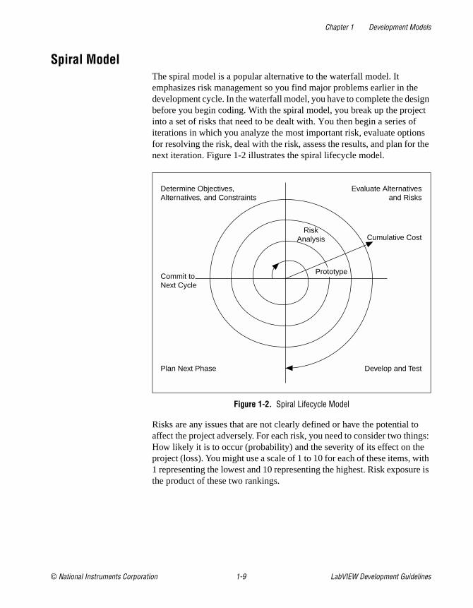
Spiral ModelThe spiral model is a popular alternative to the waterfall model. Itemphasizes risk management so you find major problems earlier in thedevelopment cycle. In the waterfall model, you have to complete the designbefore you begin coding. With the spiral model, you break up the projectinto a set of risks that need to be dealt with. You then begin a series ofiterations in which you analyze the most important risk, evaluate optionsfor resolving the risk, deal with the risk, assess the results, and plan for thenext iteration. Figure 1-2 illustrates the spiral lifecycle model.
Figure 1-2. Spiral Lifecycle Model
Risks are any issues that are not clearly defined or have the potential toaffect the project adversely. For each risk, you need to consider two things:How likely it is to occur (probability) and the severity of its effect on theproject (loss). You might use a scale of 1 to 10 for each of these items, with1 representing the lowest and 10 representing the highest. Risk exposure isthe product of these two rankings.
Cumulative Cost
Evaluate Alternativesand Risks
Determine Objectives,Alternatives, and Constraints
Develop and Test
Prototype
Plan Next Phase
Commit toNext Cycle
RiskAnalysis
Chapter 1 Development Models
LabVIEW Development Guidelines 1-10 www.ni.com
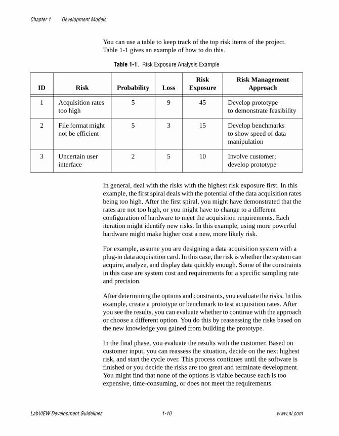
You can use a table to keep track of the top risk items of the project.Table 1-1 gives an example of how to do this.
In general, deal with the risks with the highest risk exposure first. In thisexample, the first spiral deals with the potential of the data acquisition ratesbeing too high. After the first spiral, you might have demonstrated that therates are not too high, or you might have to change to a differentconfiguration of hardware to meet the acquisition requirements. Eachiteration might identify new risks. In this example, using more powerfulhardware might make higher cost a new, more likely risk.
For example, assume you are designing a data acquisition system with aplug-in data acquisition card. In this case, the risk is whether the system canacquire, analyze, and display data quickly enough. Some of the constraintsin this case are system cost and requirements for a specific sampling rateand precision.
After determining the options and constraints, you evaluate the risks. In thisexample, create a prototype or benchmark to test acquisition rates. Afteryou see the results, you can evaluate whether to continue with the approachor choose a different option. You do this by reassessing the risks based onthe new knowledge you gained from building the prototype.
In the final phase, you evaluate the results with the customer. Based oncustomer input, you can reassess the situation, decide on the next highestrisk, and start the cycle over. This process continues until the software isfinished or you decide the risks are too great and terminate development.You might find that none of the options is viable because each is tooexpensive, time-consuming, or does not meet the requirements.
Table 1-1. Risk Exposure Analysis Example
ID Risk Probability LossRisk
ExposureRisk Management
Approach
1 Acquisition ratestoo high
5 9 45 Develop prototypeto demonstrate feasibility
2 File format mightnot be efficient
5 3 15 Develop benchmarksto show speed of datamanipulation
3 Uncertain userinterface
2 5 10 Involve customer;develop prototype
Chapter 1 Development Models
© National Instruments Corporation 1-11 LabVIEW Development Guidelines
The advantage of the spiral model over the waterfall model is that you canevaluate which risks to take care of with each cycle. Because you canevaluate risks with prototypes much earlier than in the waterfall process,you can deal with major obstacles and select alternatives in the earlierstages, which is less expensive. With a standard waterfall model, you mighthave allowed assumptions about the risky components to spread throughoutthe design, which requires much more expensive rework when theproblems are later discovered.
SummaryLifecycle models are described as distinct choices from which you mustselect. In practice, however, you can apply more than one model to a singleproject. You might start a project with a spiral model to help refine therequirements and specifications over several iterations using prototyping.Once you have reduced the risk of a poorly stated set of requirements, youmight apply a waterfall lifecycle model to the design, coding, testing, andmaintenance stages.
Other lifecycle models exist. Appendix A, References, lists documents thatcontain information about other development methodologies.
© National Instruments Corporation 2-1 LabVIEW Development Guidelines
2Incorporating Quality into theDevelopment Process
This chapter describes strategies for producing quality software.
Many developers who follow the code and fix style of programmingdescribed in Chapter 1, Development Models, mistakenly believe they donot need to deal with the issue of quality until the testing phase. This issimply not true. Design quality into a product from the start. Developingquality software begins by selecting a development model that helps youavoid problems in the first place. Consider quality during all stages ofdevelopment: requirements and specification, design, coding, testing,release, and maintenance.
Do not regard quality controls as tedious requirements that impededevelopment. Most of them help streamline development so problems arefound before they are in the software, when it is inexpensive to fix them.
Quality RequirementsSet the quality standards for a product during the requirements stage.The desired quality level is treated as a requirement, just like otherrequirements. Weigh the merits and costs of various options you have forapplying quality measures to the project. Some of the trade-offs to considerinclude speed versus robustness, and ease of use versus power andcomplexity.
For short projects, used only in-house as tools or quick prototypes, you donot need to emphasize robustness. For example, if you decide to develop aVI to benchmark I/O and graphing speeds, error checking is not as crucial.
However, with more complicated projects that must be reliable, such asapplications for monitoring and controlling a factory process, the softwaremust deal with invalid input gracefully. For example, if an operatormistakenly selects invalid voltage or current settings, the application mustdeal with it appropriately. Institute as many safeguards as possible toprevent problems. Select a lifecycle development model that helps you find
Chapter 2 Incorporating Quality into the Development Process
LabVIEW Development Guidelines 2-2 www.ni.com
problems as early as possible and allows time for formal reviews andthorough testing.
Configuration ManagementConfiguration management is the process of controlling changes andensuring they are reviewed before they are made. Chapter 1, DevelopmentModels, outlines development models, such as the waterfall model. Acentral focus of these models is to convert software development from achaotic, unplanned activity to a controlled process. These models improvesoftware development by establishing specific, measurable goals at eachstage of development.
Regardless of how well development proceeds, changes that occur later inthe process need to be implemented. It is common for customers introducenew requirements in the design stage. Performance problems discoveredduring development prompt reevaluation of the design. You might need torewrite a section of code to correct a problem found in testing. Changes canaffect any component of the project from the requirements andspecification to the design, code, and tests. If these changes are not madecarefully, you might introduce problems that can delay development ordegrade quality.
Source Code ControlAfter setting the project quality requirements, develop a process to dealwith changes. This is important for projects with multiple developers. Asthe developers work on VIs, they need a method for collecting and sharingwork. A simple method to deal with this is to establish a central sourcerepository. If each of the developer’s computers is networked, you cancreate a shared location that serves as a central source for development.When developers need to modify files, they can retrieve them from thislocation. When they are finished with the changes and the system isworking, they can return the files to this location.
Common files and areas of overlap introduce the potential for accidentalloss of work. If two developers decide to work on the same VI at the sametime, only one developer can easily merge changes into the project. Theother developer has to use the Compare VIs tool, available in the LabVIEWProfessional Development System, to determine the differences andmerge the changes into a new version. You might avoid this with goodcommunication, if each developer notifies the others when he or she needsto work on a specific VI. Inevitably, however, mistakes occur, and workis lost.

Chapter 2 Incorporating Quality into the Development Process
© National Instruments Corporation 2-3 LabVIEW Development Guidelines
Source code control tools deal with the problems of sharing VIs andcontrolling access to avoid accidental loss of data. Source code controltools make it easy to set up shared projects and to retrieve the latest filesfrom the server. Once you have created a project, you can check out a filefor development. Checking out a file marks it with your name so that noother developer can modify the file. Other developers can, however, retrievethe current version from the server. A developer can check out the file,make modifications, test the changes, and check in the file to the sourcecode system. After the file is checked in, it is accessible to the wholedevelopment team again. Another developer can then check out the file tomake further modifications.
Managing Project-Related FilesSource code control tools can manage more than just VIs. You can usethem to manage all aspects of the project—requirements, specifications,illustrations, reviews, and other documents related to the project. Thisensures that you can control access to these documents and share them asneeded. You can use the tools to track changes and access older versionsof files.
As described in Chapter 3, Prototyping and Design Techniques, sourcemanagement of all project-related files is extremely important fordeveloping quality software. In fact, source management is a requirementfor certification under existing quality standards such as ISO 9000.
Retrieving Old Versions of FilesThere are times when you need to retrieve an old version of a file or project.This might happen if you make a change to a file and check it in, only torealize you made a mistake. Another reason you might need to retrieve anold version of a file or project is if you send a beta version of the softwareto a customer and continue development. If the customer reports a problem,you might need to access a copy of the beta version of the software.
One way to access an old version of files or project is to back up filesperiodically. However, unless you back up the VI after every change, youmight not have access to every version.
Source code control tools provide a way to check in new versions of afile and make a backup copy of the old version. Depending on how youconfigure the system, the tools can maintain multiple backup copies ofa file.
Chapter 2 Incorporating Quality into the Development Process
LabVIEW Development Guidelines 2-4 www.ni.com
You can use source code control tools to label versions of files withdescriptive names like beta, v1.0, and so on. You can label any numberof files and later retrieve all versions of a file with a specific label. Whenyou release a version of the software, label the files specifically for thatversion.
Tracking ChangesIf you are managing a software project, it is important to monitor changesand track progress toward specific milestone objectives. You also can usethis information to determine problem areas of a project by identifyingwhich components required a lot of changes.
Source code control tools maintain a log of all changes made to files andprojects. When checking in a file, the developer is prompted to enter asummary of the changes made. This summary information is added to thelog for that file.
You can view the history information for a file or for the system andgenerate reports that contain that information.
In addition, if you back up the project at specific checkpoints, you can usethe Compare VIs tool to compare the latest version of a project with anotherversion to verify the changes in the project.
Change ControlLarge projects might require a formal process for evaluation and approvalof each change request. A formal evaluation system like this might be toorestrictive, so be selective when choosing the control mechanisms youintroduce into the system.
Changes to specific components, such as documents related to userrequirements, must be dealt with cautiously because they generally areworked out through several iterations with the customer. In this case, theword customer is used in a general sense. You might be your own customer,other departments in your company might be your target audience, or youmight develop the software under contract for a third party. When you areyour own customer, it is much easier to adjust requirements as you movethrough the specification and even the design stage. If you are developingfor someone else, changing requirements can be extremely difficult.
Source code control tools give you a degree of control when makingchanges. You can track all changes, and you can configure the system tomaintain previous versions so you can back out of changes if necessary.
Chapter 2 Incorporating Quality into the Development Process
© National Instruments Corporation 2-5 LabVIEW Development Guidelines
Some source code control systems give you more options for controllingsoftware change. For example, with Microsoft Visual SourceSafe, RationalSoftware ClearCase, or Perforce Software Perforce, you can control accessto files so some users have access to specific files but others do not. Youalso can specify that anyone can retrieve files but only certain users canmake modifications.
With this kind of access control, you might limit change privileges forrequirement documents to specific team members. Or, you might controlaccess so a user has privileges to modify a file only when the changerequest is approved.
The amount of control you apply can vary throughout the developmentprocess. In the early stages of the project, before formal evaluation of therequirements, you do not necessarily need to restrict change access to filesnor do you need to follow formal change request processes. Once therequirements are approved, however, you can institute stronger controls.You can apply the same concept of varying the level of control before andafter a project phase is complete to specifications, test plans, and code.
Testing GuidelinesDecide up front what level of testing is expected. Engineers under deadlinepressure frequently give short attention to testing, devoting more time toother development. Most software engineers suggest a certain level oftesting, that is guaranteed to save you time.
Developers must clearly understand the degree to which you expect testing.Also, testing methodologies must be standardized, and results of tests mustbe tracked. As you develop the requirements and design specifications, alsodevelop a test plan to help you verify that the system and all its componentswork. Testing reflects the quality goals you want to achieve. For example,if performance is more critical than robustness, develop more tests forperformance and fewer that attempt incorrect input, low-memorysituations, and so on.
Testing is not an afterthought. Consider testing as part of the initial designphases and test throughout development to find and fix problems as soon aspossible.
There are a variety of testing methodologies you can use to help increasethe quality of VI projects. The following sections describe some testingmethodologies.
Chapter 2 Incorporating Quality into the Development Process
LabVIEW Development Guidelines 2-6 www.ni.com
Black Box and White Box TestingThe method of black box testing is based on the expected functionality ofsoftware, without knowledge of how it works. It is called black box testingbecause you cannot see the internal workings. You can perform black boxtesting based largely on a knowledge of the requirements and the interfaceof a module. For a subVI, you can perform black box tests on the interfaceof a subVI to evaluate results for various input values. If robustness is aquality goal, include erroneous input data to see if the subVI deals with itwell. For example, for numeric inputs, see how the subVI deals withInfinity, Not A Number, and other out-of-range values. Refer to the UnitTesting section later in this chapter for more examples.
The method of white box testing is designed with knowledge of the internalworkings of the software. Use white box testing to check that all the majorpaths of execution are exercised. By examining a block diagram andlooking at the conditions of Case Structures and the values controllingloops, you can design tests that check those paths. White box testing ona large scale is impractical because it is difficult to test all possible paths.
Although white box testing is difficult to fully implement for largeprograms, you can choose to test the most important or complex paths.You can combine white box testing with black box testing for morethorough testing of software.
Unit, Integration, and System TestingUse black box and white box testing to test any component of software,regardless of whether it is an individual VI or the complete application.Unit testing, integration testing, and system testing are phases of the projectat which you can apply black box and white box tests.
Unit TestingYou can use unit testing to concentrate on testing individual softwarecomponents. For example, you might test an individual VI to see that itworks correctly, deals with out-of-range data, has acceptable performance,and that all major execution paths in its block diagram are executed andperformed correctly. Individual developers can perform unit tests as theywork on the modules.
Chapter 2 Incorporating Quality into the Development Process
© National Instruments Corporation 2-7 LabVIEW Development Guidelines
Some examples of common problems unit tests might account for includethe following:
• Boundary conditions for each input, such as empty arrays and emptystrings, or 0 for a size input. Be sure floating point parameters dealwith Infinity and Not A Number.
• Invalid values for each input, such as –3 for a size input.
• Strange combinations of inputs.
• Missing files and bad pathnames.
• What happens when the user clicks the Cancel button in a filedialog box?
• What happens if the user aborts the VI?
Define various sets of inputs that thoroughly test the VI and write a test VIthat calls the VI with each combination of inputs and checks the results.You can use interactive data logging to create input sets, or test vectors, andreplay them interactively to re-test the VI or automatically from a test VIthat uses programmatic data retrieval. Refer to the Unit Testing ValidationProcedure application notes for more information about testing VIs.
To perform unit testing, you might need to stub out some components thathave not been implemented yet or that are being developed. For example,if you are developing a VI that communicates with an instrument and writesinformation to a file, another developer can work on a file I/O driver thatwrites the information in a specific format. To test the components early,you might choose to stub out the file I/O driver by creating a VI with thesame interface. This VI can write the data in a format that is easy for youto check. You can test the driver with the real file I/O driver later during theintegration phase as described in the following Integration Testing section.
Regardless of how you test VIs, record exactly how, when, and what youtested and keep any test VIs you created. This test documentation isespecially important if you are creating VIs for paying customers, and it isalso useful for yourself. When you revise the VIs, run the existing tests tomake sure you have not broken anything. Also update the tests for any newfunctionality you have added.
Refer to the LabVIEW Unit Validation Test Procedure application note formore information about unit testing.
Chapter 2 Incorporating Quality into the Development Process
LabVIEW Development Guidelines 2-8 www.ni.com
Integration TestingYou perform integration testing on a combination of units. Unit testingusually finds most bugs, but integration testing might reveal unanticipatedproblems. Modules might not work together as expected. They mightinteract in unexpected ways because of the way they manipulate shareddata. Refer to the LabVIEW Performance application note for moreinformation about possible problems that are discovered during testing.
You also can perform integration testing in earlier stages before you put thewhole system together. For example, if a developer creates a set of VIs thatcommunicates with an instrument, he or she can develop unit tests to verifythat each subVI correctly sends the appropriate commands. He or she alsocan develop integration tests that use several of the subVIs in conjunctionwith each other to verify that there is not any unexpected interaction.
Do not perform integration testing as a comprehensive test in which youcombine all the components and try to test the top-level program. Doingthis can be expensive because it is difficult to determine the specific sourceof problems within a large set of VIs. Instead, consider testingincrementally with a top-down or bottom-up testing approach.
With a top-down approach, you gradually integrate major components,testing the system with the lower level components of the system disabled,or stubbed out, as described in the Unit Testing section earlier in thischapter. Once you have verified that the existing components work togetherwithin the existing framework, you can enable additional components.
With a bottom-up approach, you test low-level modules first and graduallywork up toward the high-level modules. Begin by testing a small number ofcomponents combined into a simple system, such as the driver testdescribed in the Unit Testing section earlier in this chapter. After you havecombined a set of modules and verified that they work together, addcomponents and test them with the already-debugged subsystem.
The bottom-up approach consists of tests that gradually increase in scope,while the top-down approach consists of tests that are gradually refined asnew components are added.
Regardless of the approach you take, you must perform regression testingat each step to verify that the features that already have been tested stillwork. Regression testing consists of repeating some or all previous tests.Because you might need to perform the same tests numerous times, youmight want to develop representative subsets of tests to use for frequentregression tests. You can run these components at each stage, while the
Chapter 2 Incorporating Quality into the Development Process
© National Instruments Corporation 2-9 LabVIEW Development Guidelines
more detailed tests can be run to test an individual set of modules ifproblems are encountered or as part of a more detailed regression test thatis applied periodically during development.
System TestingSystem testing happens after integration to determine if the product meetscustomer expectations and to make sure the software works as expectedwithin the hardware system. You can do this as a set of black box tests toverify that the requirements have been met. Most LabVIEW applicationsperform some kind of I/O. The application also might communicate withother applications. With system testing, you test the software to make sureit fits into the overall system as expected. When testing the system, ask andanswer questions such as the following:
• Are performance requirements met?
• If my application communicates with another application, does it dealwith an unexpected failure of that application well?
You can complete this testing with alpha and beta testing. Alpha and betatesting serve to catch test cases that might not have been considered orcompleted by the developers. With alpha testing, a functionally completeproduct is tested in-house to see if any problems are found. When alphatesting is complete, the product is beta tested by customers in the field.
Alpha and beta testing are the only testing mechanisms for somecompanies. This is unfortunate because alpha and beta testing actually canbe inexact. Alpha and beta testing are not a substitute for other forms oftesting that rigorously test each component to verify that it meets statedobjectives. Because this type of testing is done late in the developmentprocess, it is difficult and costly to incorporate changes suggested as aresult.
Formal Methods of VerificationSome software engineers are proponents of formal verification of software.Other testing methodologies attempt to find problems by exploration, butformal methods attempt to prove the correctness of softwaremathematically.
The principal idea is to analyze each function of a program to determine ifit does what you expect. You mathematically state the list of preconditionsbefore the function and the postconditions that are present as a result of thefunction. You can perform this process either by starting at the beginning ofthe program and adding conditions as you work through each function or
Chapter 2 Incorporating Quality into the Development Process
LabVIEW Development Guidelines 2-10 www.ni.com
by starting at the end and working backward, developing a set of weakestpreconditions for each function. Refer to Appendix A, References, for a listof documents that include more information about the verification process.
This type of testing becomes more complex as more and more possiblepaths of execution are added to a program through the use of loops andconditions. Many people believe that formal testing presents interestingideas for looking at software that can help in small cases but that it isimpractical for most programs.
Style GuidelinesInconsistent approaches to development and to user interfaces can be aproblem when multiple developers work on a project. Each developerhas his or her own style of development, color preferences, displaytechniques, documentation practices, and block diagram methodologies.One developer might make extensive use of global variables and SequenceStructures while another might prefer to make more use of data flow.
Inconsistent style techniques can create software that, at a minimum, looksbad. Users might become confused and find the user interface VIs difficultto use if the VIs have different behaviors, such as some expecting a user toclick a button when he or she is finished and others expecting the user touse a keyboard function key.
Inconsistent style also makes software difficult to maintain. For example,if one developer does not like to use subVIs and decides to develop allfeatures within a single large VI, that VI is difficult to modify.
Establish a set of guidelines for your VI development team. Establish aninitial set of guidelines and add additional rules as the project progresses.You can use these style guidelines in future projects.
Chapter 6, LabVIEW Style Guide, provides some style recommendations.Use these guidelines as a basis for developing your own style guide.A single standard for programming style in any language really cannotexist because what one group prefers, another group might disagree with.Select a set of guidelines that works for you and your development team.
Chapter 2 Incorporating Quality into the Development Process
© National Instruments Corporation 2-11 LabVIEW Development Guidelines
Design ReviewsDesign reviews are a great way to identify and fix problems duringdevelopment. When the design of a feature is complete, set up a designreview with at least one other developer. Discuss quality goals, askingquestions such as the following:
• Does the design incorporate testing?
• Is error handling built-in?
• Are there any assumptions in the system that might be invalid?
Also, look at the design with an eye for features that are essential asopposed to features that are extras. There is nothing wrong with building inextra features. If quality and schedule are important, however, ensure thatthese extra features are scheduled for late in the development process, sothey can be dropped, or moved to the list of features for subsequentreleases. Document the results of the design review and any recommendedchanges.
Code WalkthroughsA code walkthrough is similar to a design review except that it analyzesthe code instead of the design. To perform a code review, give one or moredevelopers printouts of the VIs to review. You might want to perform thereview online because VIs are easier to read and navigate online. It is wisefor the designer talk through the design. The reviewers compare thedescription to the actual implementation. The reviewers must considermany of the same issues included in a design review. During a codewalkthrough, many of the following questions might be asked andanswered:
• What happens if a specific VI or function returns an error? Are errorsdealt with and/or reported correctly?
• Are there any race conditions? An example of a race condition is ablock diagram that reads from and writes to a global variable. There isthe potential that a parallel block diagram simultaneously attempts tomanipulate the same global variable, resulting in loss of data.
Chapter 2 Incorporating Quality into the Development Process
LabVIEW Development Guidelines 2-12 www.ni.com
• Is the block diagram implemented well? Are the algorithms efficient interms of speed and/or memory usage? Refer to the LabVIEWPerformance application note for more information about creatingeffective code.
• Is the block diagram easy to maintain? Has the developer made gooduse of hierarchy, or is he or she placing too much functionality in asingle VI? Does the developer adhere to established guidelines?
There are a number of other features you can look for in a codewalkthrough. Take notes on the problems you encounter and add them to alist you can use as a guideline for other walkthroughs.
Focus on technical issues when doing a code walkthrough. Remember toreview only the code, not the developer who produced it. Try not to focusonly on the negative and be sure to raise positive points.
Refer to Appendix A, References, for a list of documents that include moreinformation about walkthrough techniques.
Postmortem EvaluationAt the end of each stage in the development process, consider having apostmortem meeting to discuss what has gone well and what has not. Eachdeveloper must evaluate the project honestly and discuss obstacles thatreduce the quality level of the project. Each developer must consider thefollowing questions:
• What are we doing right? What is working well?
• What are we doing wrong? What can we improve?
• Are there specific areas of the design/code that need a lot of work?Is a design review or code walkthrough of that section necessary?
• Are the quality systems working? Can we catch more problems if wechanged the quality requirements? Are there better ways to get thesame results?
Postmortem meetings at major milestones can help to correct problemsmid-schedule instead of waiting until the release is complete.
Chapter 2 Incorporating Quality into the Development Process
© National Instruments Corporation 2-13 LabVIEW Development Guidelines
Software Quality StandardsAs software has become a more critical component in systems, concernsabout software quality have increased. Consequently, a number oforganizations have developed quality standards that are specific to softwareor that can be applied to software. When developing software for somelarge organizations, especially government organizations, you might berequired to follow one of these standards.
The following sections include a brief overview of the most popularstandards. Refer to Appendix A, References, for a list of documents thatinclude more information about these standards.
International Organization for Standardization ISO 9000The International Organization for Standardization (ISO) developed theISO 9000 family of standards for quality management and assurance.Many countries have adopted these standards. In some cases, governmentalbodies require compliance with this ISO standard. Compliance generallyis measured by certification performed by a third-party auditor. TheISO 9000 family is widely used within Europe and Asia. It has not beenwidely adopted within the United States, although many companies andsome government agencies are begining to use it.
In each country, the ISO family of standards are referred to by slightlydifferent names. For example, in the United States it has been adoptedas the ANSI/American Society for Quality Control (ASQC) Q90 Series.In Europe, it has been adopted by the European Committee forStandardization (CEN) and the European Committee for ElectrotechnicalStandardization (CENELEC) as the European Norm (EN) 29000 Series.In Canada, it has been adopted by the Canadian Standards Association(CSA) as the Q 9000 series. However, it is most commonly referred to asISO 9000 in all countries.
ISO 9000 is an introduction to the ISO 9000 family of standards. ISO 9001is a model for quality assurance in design, development, production,installation, and servicing. Its focus on design and development makes itthe most appropriate standard for software products.
Because the ISO 9000 family is designed to apply to any industry, it issomewhat difficult to apply to software development. ISO 9000.3 is a setof guidelines designed to explain how to apply ISO 9001 specifically tosoftware development.
Chapter 2 Incorporating Quality into the Development Process
LabVIEW Development Guidelines 2-14 www.ni.com
ISO 9001 does not dictate software development procedures. Instead, itrequires documentation of development procedures and adherence to thestandards you set. Conformance with ISO 9001 does not guarantee quality.Instead, the idea behind ISO 9001 is that companies that emphasize qualityand follow their documented practices produce higher quality products thancompanies that do not.
U.S. Food and Drug Administration StandardsThe U.S. Food and Drug Administration (FDA) requires all software usedin medical applications to meet its Current Good Manufacturing Practices(CGMP). One of the goals of the standard is to make it as consistent aspossible with ISO 9001 and a supplement to ISO 9001, ISO/CD 13485.These FDA standards are largely consistent with ISO 9001, but there aresome differences. Specifically, the FDA did not think ISO 9001 wasspecific enough about certain requirements, so the FDA clearly outlinedthem in its rules.
Refer to the FDA web site at http://www.fda.gov for more informationabout the CGMP rules and how they compare to ISO 9001.
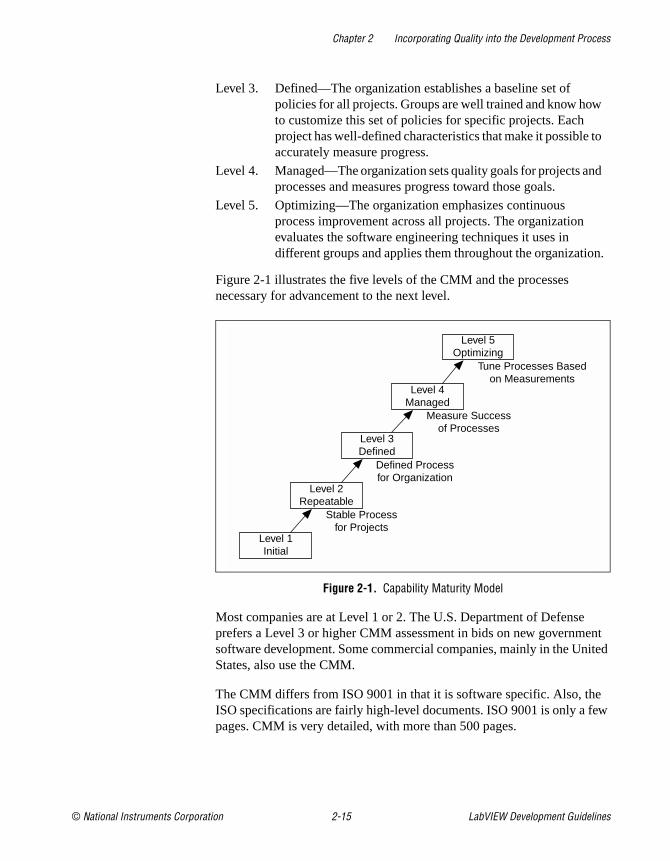
Capability Maturity Model (CMM)In 1984, the United States Department of Defense created the SoftwareEngineering Institute (SEI) to establish standards for software quality. TheSEI developed a model for software quality called the Capability MaturityModel (CMM). The CMM focuses on improving the maturity of anorganization’s processes.
Whereas ISO establishes only two levels of conformance, pass or fail, theCMM ranks an organization into one of five categories.
Level 1. Initial—The organization has few defined processes; qualityand schedules are unpredictable.
Level 2. Repeatable—The organization establishes policies based onsoftware engineering techniques and previous projects thatallow repeated success. Groups use configuration managementtools to manage projects. Also, they track software costs,features, and schedules. Project standards are defined andfollowed. Although the groups can deal with similar projectsbased on this experience, their processes might not be matureenough to deal with significantly different types of projects.
Chapter 2 Incorporating Quality into the Development Process
© National Instruments Corporation 2-15 LabVIEW Development Guidelines
Figure 2-1 illustrates the five levels of the CMM and the processesnecessary for advancement to the next level.
Figure 2-1. Capability Maturity Model
Most companies are at Level 1 or 2. The U.S. Department of Defenseprefers a Level 3 or higher CMM assessment in bids on new governmentsoftware development. Some commercial companies, mainly in the UnitedStates, also use the CMM.
The CMM differs from ISO 9001 in that it is software specific. Also, theISO specifications are fairly high-level documents. ISO 9001 is only a fewpages. CMM is very detailed, with more than 500 pages.
Level 3. Defined—The organization establishes a baseline set ofpolicies for all projects. Groups are well trained and know howto customize this set of policies for specific projects. Eachproject has well-defined characteristics that make it possible toaccurately measure progress.
Level 4. Managed—The organization sets quality goals for projects andprocesses and measures progress toward those goals.
Level 5. Optimizing—The organization emphasizes continuousprocess improvement across all projects. The organizationevaluates the software engineering techniques it uses indifferent groups and applies them throughout the organization.
Level 5Optimizing
Level 4Managed
Level 3Defined
Tune Processes Basedon Measurements
Measure Successof Processes
Defined Processfor Organization
Stable Processfor Projects
Level 2Repeatable
Level 1Initial
Chapter 2 Incorporating Quality into the Development Process
LabVIEW Development Guidelines 2-16 www.ni.com
Institute of Electrical and Electronic Engineers (IEEE) StandardsIEEE defined a number of standards for software engineering.IEEE Standard 730, first published in 1980, is a standard for softwarequality assurance plans. This standard serves as a foundation for severalother IEEE standards and gives a brief description of the minimumrequirements for a quality plan in the following areas:
• Purpose
• Reference documents
• Management
• Documentation
• Standards, practices, conventions, and metrics
• Reviews and audits
• Test
• Problem reporting and corrective action
• Tools, techniques, and methodologies
• Code control
• Media control
• Supplier control
• Records collection, maintenance, and retention
• Training
• Risk management
As with the ISO standards, IEEE 730 is fairly short. It does not dictate howto meet the requirements but requires documentation for these practices toa specified minimum level of detail.
In addition to IEEE 730, several other IEEE standards related to softwareengineering exist, including the following:
• IEEE 610—Defines standard software engineering terminology.
• IEEE 829—Establishes standards for software test documentation.
• IEEE 830—Explains the content of good software requirementsspecifications.
• IEEE 1074—Describes the activities performed as part of a softwarelifecycle without requiring a specific lifecycle model.
• IEEE 1298—Details the components of a software qualitymanagement system; similar to ISO 9001.

Chapter 2 Incorporating Quality into the Development Process
© National Instruments Corporation 2-17 LabVIEW Development Guidelines
Your projects might be required to meet some or all these standards. Evenif you are not required to develop to any of these specifications, they can behelpful in developing your own requirements, specifications, and qualityplans.
© National Instruments Corporation 3-1 LabVIEW Development Guidelines
3Prototyping and DesignTechniques
This chapter gives you pointers for project design, including programmingapproaches, prototyping, and benchmarking.
When you first begin a programming project, deciding how to start can beintimidating. Many LabVIEW developers start immediately with a codeand fix development process, building some of the VIs they think areneeded. Then they realize they actually need something different from whatthey have built already. Consequently, a lot of code is developed, reworked,or thrown away unnecessarily.
Clearly Define the Requirements of the ApplicationBefore you develop a detailed design of a system, define goals as clearly aspossible. Begin by making a list of requirements. Some requirements arespecific, such as the types of I/O, sampling rates, or the need for real-timeanalysis. You need to do some research at this early stage to be sure youcan meet the specifications. Other requirements depend on userpreferences, such as file formats or graph styles.
Try to distinguish between absolute requirements and desires. You might beable to satisfy all requests, but it is best to have an idea about what you cansacrifice if you run out of time.
Also, be careful that the requirements are not so detailed that they constrainthe design. For example, when you design an I/O system, the customerprobably has certain sampling rate and precision requirements. He or shealso is constrained by cost. Include those issues in the requirements.However, if you can avoid specifying the operating system and hardware,you can adjust the design after you begin prototyping and benchmarkingvarious components. As long as the costs are within budget and the timingand precision issues are met, the customer might not care whether thesystem uses a particular type of plug-in card or other hardware.

Chapter 3 Prototyping and Design Techniques
LabVIEW Development Guidelines 3-2 www.ni.com
Another example of overly constraining a design is to be too specific aboutthe format for display used in various screens with which the customerinteracts. A picture of a display might be useful to explain requirements, butbe clear about whether the picture is a requirement or a guideline. Somedesigners go through significant difficulties trying to produce a system thatbehaves in a specific way because a certain behavior was a requirement. Inthis case, there might be a simpler solution that produces the same resultsat a much lower cost in a shorter time.
Top-Down DesignThe block diagram programming metaphor LabVIEW uses was designedto be easy to understand. Most engineers already use block diagrams todescribe systems. The goal of the block diagram is to make it easier for youto move from the system block diagrams you create to executable code.
The basic concept is to divide the task into manageable pieces at logicalplaces. Begin with a high-level block diagram that describes the maincomponents of the VI. For example, you might have a block diagram thatconsists of a block for configuration, a block for acquisition, a block foranalysis of the acquired data, a block for displaying the results, a block forsaving the data to disk, and a block to clean up at the end of the VI.
After you determine the high-level blocks, create a block diagram thatuses those blocks. For each block, create a new stub VI, which is anon-functional prototype that represents a future subVI. Create an icon forthis stub VI and create a front panel with the necessary inputs and outputs.You do not have to create a block diagram for this VI yet. Instead, definethe interface and see if this stub VI is a useful part of the top-level blockdiagram.
After you assemble a group of these stub VIs, determine the function ofeach block and how it works. Ask yourself whether any given blockgenerates information that a subsequent VI needs. If so, make sure thetop-level block diagram sketch contains wires to pass the data between theVIs. You can document the functionality of the VI and the inputs andoutputs using the Documentation page of the VI Properties dialog box inLabVIEW.
In analyzing the transfer of data from one block to another, try to avoidglobal variables because they hide the data dependency among VIs andmight introduce race conditions. Refer to the LabVIEW Performanceapplication notes for more information about issues that might arise when
Chapter 3 Prototyping and Design Techniques
© National Instruments Corporation 3-3 LabVIEW Development Guidelines
creating VIs. As the VI becomes larger, it becomes difficult to debug if youuse global variables as the method of transferring information among VIs.
Continue to refine the design by breaking down each of the componentblocks into more detailed outlines. You can do this by going to the blockdiagram of what was once a stub VI and filling out its block diagram,placing lower level stub VIs on the block diagram that represent each of themajor actions the VI must perform.
Be careful not to jump too quickly into implementing the system at thispoint. One of the objectives here is to gradually refine the design so you candetermine if you have left out any necessary components at higher levels.For example, when refining the acquisition phase, you might realize thereis more information you need from the configuration phase. If youcompletely implement one block before you analyze a subsequent block,you might need to redesign the first block significantly. It is better to try torefine the system gradually on several fronts, with particular attention tosections that have more risk because of the complexity.
Data Acquisition System ExampleThis example describes how you might apply top-down design techniquesto a data acquisition system. This system must let the user provide someconfiguration of the acquisition, such as rates, channels, and so on; acquiredata; process the data; and save the data to disk.
Start to design the VI hierarchy by breaking the problem into logical pieces.The flowchart in Figure 3-1 shows several major blocks you can expect tosee in one form or another in every data acquisition system.
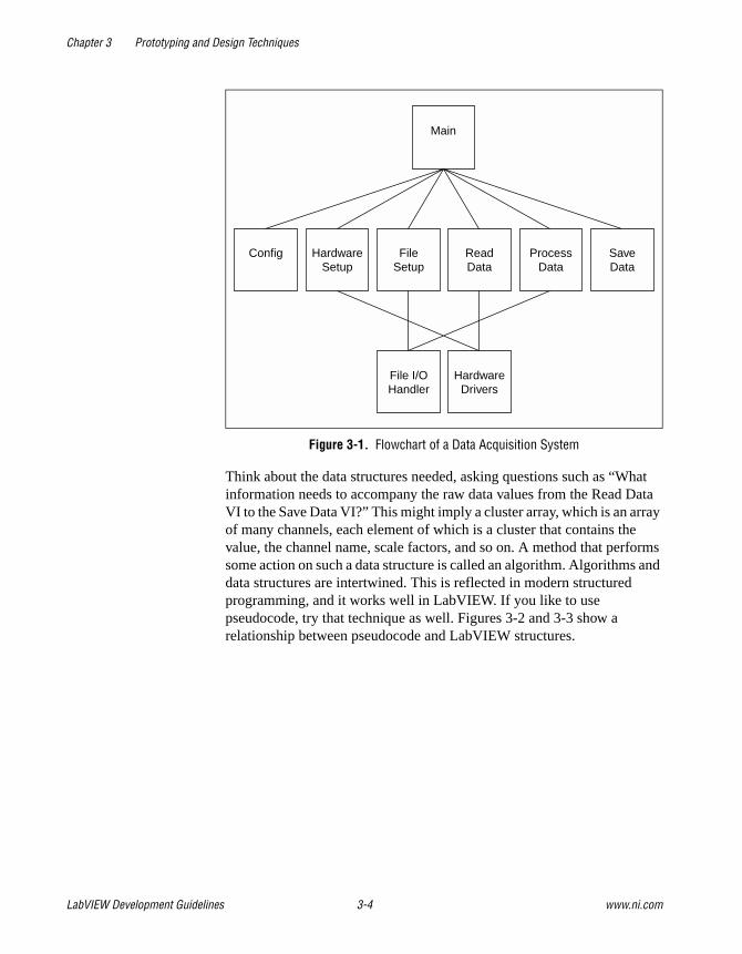
Chapter 3 Prototyping and Design Techniques
LabVIEW Development Guidelines 3-4 www.ni.com
Figure 3-1. Flowchart of a Data Acquisition System
Think about the data structures needed, asking questions such as “Whatinformation needs to accompany the raw data values from the Read DataVI to the Save Data VI?” This might imply a cluster array, which is an arrayof many channels, each element of which is a cluster that contains thevalue, the channel name, scale factors, and so on. A method that performssome action on such a data structure is called an algorithm. Algorithms anddata structures are intertwined. This is reflected in modern structuredprogramming, and it works well in LabVIEW. If you like to usepseudocode, try that technique as well. Figures 3-2 and 3-3 show arelationship between pseudocode and LabVIEW structures.
Config HardwareSetup
FileSetup
ReadData
Main
File I/OHandler
HardwareDrivers
ProcessData
SaveData
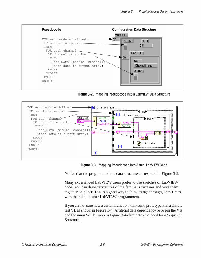
Chapter 3 Prototyping and Design Techniques
© National Instruments Corporation 3-5 LabVIEW Development Guidelines
Figure 3-2. Mapping Pseudocode into a LabVIEW Data Structure
Figure 3-3. Mapping Pseudocode into Actual LabVIEW Code
Notice that the program and the data structure correspond in Figure 3-2.
Many experienced LabVIEW users prefer to use sketches of LabVIEWcode. You can draw caricatures of the familiar structures and wire themtogether on paper. This is a good way to think things through, sometimeswith the help of other LabVIEW programmers.
If you are not sure how a certain function will work, prototype it in a simpletest VI, as shown in Figure 3-4. Artificial data dependency between the VIsand the main While Loop in Figure 3-4 eliminates the need for a SequenceStructure.
Pseudocode Configuration Data Structure
FOR each module defined IF module is active THEN FOR each channel IF channel is active THEN Read_Data (module, channel); Store data in output array; ENDIF ENDFOR ENDIFENDFOR
FOR each module defined IF module is active THEN FOR each channel IF channel is active THEN Read_Data (module, channel); Store data in output array; ENDIF ENDFOR ENDIFENDFOR

Chapter 3 Prototyping and Design Techniques
LabVIEW Development Guidelines 3-6 www.ni.com
Figure 3-4. Data Flow for a Generic Data Acquisition Program
Finally, you are ready to write the program in LabVIEW. Remember tomake the code modular, building subVIs when there is a logical division oflabor or the potential for code reuse. Solve the more general problems alongwith the specific ones. Test the subVIs as you write them. This mightinvolve constructing higher level test routines. It is much easier to catch theproblems in one small module than in a large hierarchy of VIs.
Bottom-Up DesignUsually, avoid bottom-up system design. It is sometimes useful when usedin conjunction with top-down design, with bottom-up design, you start bybuilding the lower level components and then progressing up the hierarchy,gradually putting pieces together until you have the complete system.
The problem with bottom-up design is that because you do not start with aclear idea of the big picture, you might build pieces that do not fit togetherthe way you expect.
There are specific cases in which using bottom-up design is appropriate.If the design is constrained by low-level functionality, you might need tobuild that low-level functionality first to get an idea of how it can be used.This might be true of an instrument driver, where the command set for theinstrument constrains you in terms of when you can do certain operations.For example, with a top-down design, you might break up the design soconfiguration of the instrument and reading a measurement from theinstrument are done in distinct VIs. The instrument command set mightturn out to be more constraining than you thought, requiring you tocombine these operations. In this case, with a bottom-up strategy, youmight start by building VIs that deal with the instrument command set.
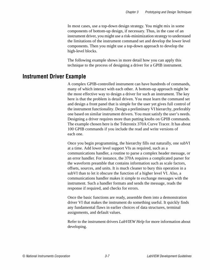
Chapter 3 Prototyping and Design Techniques
© National Instruments Corporation 3-7 LabVIEW Development Guidelines
In most cases, use a top-down design strategy. You might mix in somecomponents of bottom-up design, if necessary. Thus, in the case of aninstrument driver, you might use a risk-minimization strategy to understandthe limitations of the instrument command set and develop the lower levelcomponents. Then you might use a top-down approach to develop thehigh-level blocks.
The following example shows in more detail how you can apply thistechnique to the process of designing a driver for a GPIB instrument.
Instrument Driver ExampleA complex GPIB-controlled instrument can have hundreds of commands,many of which interact with each other. A bottom-up approach might bethe most effective way to design a driver for such an instrument. The keyhere is that the problem is detail driven. You must learn the command setand design a front panel that is simple for the user yet gives full control ofthe instrument functionality. Design a preliminary VI hierarchy, preferablyone based on similar instrument drivers. You must satisfy the user’s needs.Designing a driver requires more than putting knobs on GPIB commands.The example chosen here is the Tektronix 370A Curve Tracer. It has about100 GPIB commands if you include the read and write versions ofeach one.
Once you begin programming, the hierarchy fills out naturally, one subVIat a time. Add lower level support VIs as required, such as acommunications handler, a routine to parse a complex header message, oran error handler. For instance, the 370A requires a complicated parser forthe waveform preamble that contains information such as scale factors,offsets, sources, and units. It is much cleaner to bury this operation in asubVI than to let it obscure the function of a higher level VI. Also, acommunications handler makes it simple to exchange messages with theinstrument. Such a handler formats and sends the message, reads theresponse if required, and checks for errors.
Once the basic functions are ready, assemble them into a demonstrationdriver VI that makes the instrument do something useful. It quickly findsany fundamental flaws in earlier choices of data structures, terminalassignments, and default values.
Refer to the instrument drivers LabVIEW Help for more information aboutdeveloping.
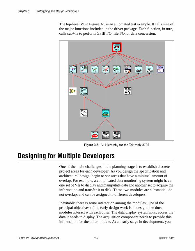
Chapter 3 Prototyping and Design Techniques
LabVIEW Development Guidelines 3-8 www.ni.com
The top-level VI in Figure 3-5 is an automated test example. It calls nine ofthe major functions included in the driver package. Each function, in turn,calls subVIs to perform GPIB I/O, file I/O, or data conversion.
Figure 3-5. VI Hierarchy for the Tektronix 370A
Designing for Multiple DevelopersOne of the main challenges in the planning stage is to establish discreteproject areas for each developer. As you design the specification andarchitectural design, begin to see areas that have a minimal amount ofoverlap. For example, a complicated data monitoring system might haveone set of VIs to display and manipulate data and another set to acquire theinformation and transfer it to disk. These two modules are substantial, donot overlap, and can be assigned to different developers.
Inevitably, there is some interaction among the modules. One of theprincipal objectives of the early design work is to design how thosemodules interact with each other. The data display system must access thedata it needs to display. The acquisition component needs to provide thisinformation for the other module. At an early stage in development, you
Chapter 3 Prototyping and Design Techniques
© National Instruments Corporation 3-9 LabVIEW Development Guidelines
might design the connector panes of VIs needed to transfer informationbetween the two modules. Likewise, if there are global data structuresthat must be shared, analyze and define them early in the architecturaldesign stage before the individual developers begin work on thecomponents.
In the early stages, each developer can create stub VIs with the connectorpane interface that was defined for the shared module. This stub VI can donothing, or, if it is a VI that returns information, you might have it generaterandom data. This allows each member of the development team tocontinue development without having to wait for the other modules to befinished. It also makes it easy for the individuals to perform unit testing ofmodules as described in Chapter 2, Incorporating Quality into theDevelopment Process.
As components near completion, you can integrate the modules byreplacing the stub components with the real counterparts. At this point youcan perform integration testing to verify the system works as a whole. Referto the Integration Testing section in Chapter 2, Incorporating Quality intothe Development Process, for more information about integration testing.
Front Panel PrototypingAs mentioned in Chapter 1, Development Models, front panel prototypescan provide insight into the organization of the program. Assuming theprogram is user-interface intensive, you can attempt to create a mockinterface that represents what the user sees.
Avoid implementing block diagrams in the early stages of creatingprototypes so you do not fall into the code and fix trap. Instead, create justthe front panels. As you create buttons, listboxes, and rings, think aboutwhat needs to happen as the user makes selections. Ask yourself questionssuch as the following:
• Should the button lead to another front panel?
• Should some controls on the front panel be hidden and replaced byothers?
If new options are presented, follow those ideas by creating new frontpanels to illustrate the results. This kind of prototyping can help solidify therequirements for a project and give you a better idea of its scope.
Prototyping cannot solve all development problems, however. You have tobe careful how you present the prototype to customers. Prototypes can give

Chapter 3 Prototyping and Design Techniques
LabVIEW Development Guidelines 3-10 www.ni.com
an overly inflated sense that you are rapidly making progress on the project.You have to be clear to the customer, whether it is an external customer orother members of your company, that this prototype is strictly for designpurposes and that much of it is reworked in the development phase.
Another danger in prototyping is that you might overdo it. Consider settingstrict time goals for the amount of time you prototype a system to preventyourself from falling into the code and fix trap.
Of course, front panel prototyping deals only with user interfacecomponents. As described here, it does not deal with I/O constraints, datatypes, or algorithm issues in the design. The front panel issues might helpyou better define some of these areas because it gives you an idea of someof the major data structures you need to maintain, but it does not deal withall these issues. For those issues, you need to use one of the other methodsdescribed in this chapter, such as performance benchmarking and top-downdesign.
Performance BenchmarkingFor I/O systems with a number of data points or high transfer raterequirements, test the performance-related components early because thetest might prove that the design assumptions are incorrect.
For example, if you plan to use an instrument as the data acquisitionsystem, you might want to build some simple tests that perform the type ofI/O you plan to use. While the specifications might seem to indicate that theinstrument can handle the application you are creating, you might find thattriggering, for example, takes longer than you expected, that switchingbetween channels with different gains cannot be done at the necessary ratewithout reducing the accuracy of the sampling, or that even though theinstrument can handle the rates, you do not have enough time on thesoftware side to perform the desired analysis.
A simple prototype of the time-critical sections of the application canhelp reveal this kind of problem. The timing template example in theexamples/general/structs.llb directory illustrates how to time aprocess. Because timings can fluctuate from one run to another for a varietyof reasons, put the operation in a loop and display the average executiontime. You also can use a graph to display timing fluctuations. Causes oftiming fluctuations can include system interrupts, screen updates, userinteraction, and initial buffer allocation.
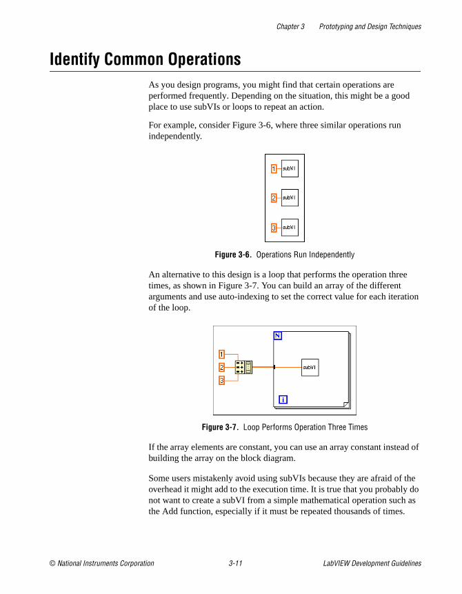
Chapter 3 Prototyping and Design Techniques
© National Instruments Corporation 3-11 LabVIEW Development Guidelines
Identify Common OperationsAs you design programs, you might find that certain operations areperformed frequently. Depending on the situation, this might be a goodplace to use subVIs or loops to repeat an action.
For example, consider Figure 3-6, where three similar operations runindependently.
Figure 3-6. Operations Run Independently
An alternative to this design is a loop that performs the operation threetimes, as shown in Figure 3-7. You can build an array of the differentarguments and use auto-indexing to set the correct value for each iterationof the loop.
Figure 3-7. Loop Performs Operation Three Times
If the array elements are constant, you can use an array constant instead ofbuilding the array on the block diagram.
Some users mistakenly avoid using subVIs because they are afraid of theoverhead it might add to the execution time. It is true that you probably donot want to create a subVI from a simple mathematical operation such asthe Add function, especially if it must be repeated thousands of times.

Chapter 3 Prototyping and Design Techniques
LabVIEW Development Guidelines 3-12 www.ni.com
However, the overhead for a subVI is fairly small and usually is dwarfedby any I/O you perform or by any memory management that might occurfrom complex manipulation of arrays.

© National Instruments Corporation 4-1 LabVIEW Development Guidelines
4Scheduling and Project Tracking
This chapter describes techniques for estimating development time andusing those estimates to create schedules. This chapter also distinguishesbetween an estimate, which reflects the time required to implement afeature, and a schedule, which reflects how you fulfill that feature.Estimates are commonly expressed in ideal person-days, or 8 hours ofwork. In creating a schedule from estimates, you must considerdependencies—one project might have to be completed before anothercan begin—and other tasks, such as meetings, support for existing projects,and so on.
EstimationOne of the principle tasks of planning is to estimate the size of the projectand fit it into the schedule because most projects are at least partially drivenby a schedule. Schedule, resources, and critical requirements interact todetermine what you can implement in a release.
Unfortunately, when it comes to estimating software schedules accurately,few people are successful. Major companies have had software projectsexceed original estimates by a year or more. Poor planning or anincomplete idea of project goals often causes deadlines to be missed.Another major cause of missed schedules is feature creep: The designgradually grows to include features that were not part of the originalrequirements. In many cases, the delays in schedule are a result of usinga code and fix development process rather than a more measurabledevelopment model.
Off-the-cuff estimates are almost never accurate for the following reasons:
• People are usually overly optimistic. An estimate of two months at firstmight seem like an infinite amount of time. During the last two weeksof the project, when developers find themselves working manyovertime hours, it becomes clear that it is not.
• The objectives, implementation issues, and quality requirements arenot understood clearly. When challenged with the task of creating adata monitoring system, an engineer might estimate two weeks. If theproduct is designed by the engineer and for the engineer, this estimate
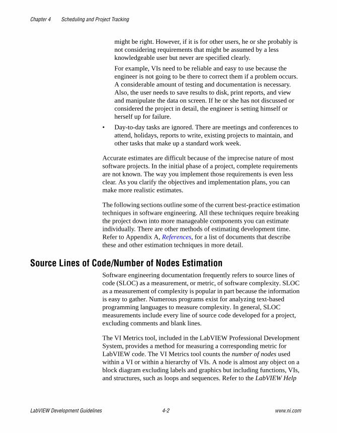
Chapter 4 Scheduling and Project Tracking
LabVIEW Development Guidelines 4-2 www.ni.com
might be right. However, if it is for other users, he or she probably isnot considering requirements that might be assumed by a lessknowledgeable user but never are specified clearly.
For example, VIs need to be reliable and easy to use because theengineer is not going to be there to correct them if a problem occurs.A considerable amount of testing and documentation is necessary.Also, the user needs to save results to disk, print reports, and viewand manipulate the data on screen. If he or she has not discussed orconsidered the project in detail, the engineer is setting himself orherself up for failure.
• Day-to-day tasks are ignored. There are meetings and conferences toattend, holidays, reports to write, existing projects to maintain, andother tasks that make up a standard work week.
Accurate estimates are difficult because of the imprecise nature of mostsoftware projects. In the initial phase of a project, complete requirementsare not known. The way you implement those requirements is even lessclear. As you clarify the objectives and implementation plans, you canmake more realistic estimates.
The following sections outline some of the current best-practice estimationtechniques in software engineering. All these techniques require breakingthe project down into more manageable components you can estimateindividually. There are other methods of estimating development time.Refer to Appendix A, References, for a list of documents that describethese and other estimation techniques in more detail.
Source Lines of Code/Number of Nodes EstimationSoftware engineering documentation frequently refers to source lines ofcode (SLOC) as a measurement, or metric, of software complexity. SLOCas a measurement of complexity is popular in part because the informationis easy to gather. Numerous programs exist for analyzing text-basedprogramming languages to measure complexity. In general, SLOCmeasurements include every line of source code developed for a project,excluding comments and blank lines.
The VI Metrics tool, included in the LabVIEW Professional DevelopmentSystem, provides a method for measuring a corresponding metric forLabVIEW code. The VI Metrics tool counts the number of nodes usedwithin a VI or within a hierarchy of VIs. A node is almost any object on ablock diagram excluding labels and graphics but including functions, VIs,and structures, such as loops and sequences. Refer to the LabVIEW Help

Chapter 4 Scheduling and Project Tracking
© National Instruments Corporation 4-3 LabVIEW Development Guidelines
for more information about how to use this tool and the accountingmechanism it uses.
You can use number of nodes as a method for estimating future projectdevelopment efforts. For this to work, you must build a base of knowledgeabout current and previous projects. You must have an idea of the amountof time it took to develop components of existing software products andassociate that information with the number of nodes used in thatcomponent.
Armed with this historical information, you next need to estimate thenumber of nodes required for a new project. It is not possible to do this foran entire project at once. Instead, you must break the project down intosubprojects you can compare to other tasks completed in the past. Once youhave broken it down, you can estimate each component and produce a totalestimate of the number of nodes and the time required for development.
Problems with Source Lines of Codeand Number of NodesSize-based metrics are not uniformly accepted in software engineering.Many people favor them because it is a relatively easy metric to gatherand because a lot of literature has been written about it. Detractors of sizemetrics point out the following flaws:
• Size-based metrics are dependent on the organization. Lines ofcode/numbers of nodes can be useful within an organization as long asyou are dealing with the same group of people and they are followingthe same style guidelines. Trying to use size metrics from othercompanies/groups can be difficult because of differing levels ofexperience, different expectations for testing and developmentmethodologies, and so on.
• Size-based metrics are also dependent on the programming language.Comparing a line of code in assembly language to one written in C canbe like comparing apples to oranges. Statements in higher levellanguages can provide more functionality than those in lower levellanguages. Comparing numbers of nodes in LabVIEW to lines of codein a text-based programming language can be inexact for this reason.
• Not all code is created with the same level of quality. A VI thatretrieves information from a user and writes it to a file can be writtenso efficiently that it involves a small number of nodes or it can bewritten poorly with a large number of nodes.

Chapter 4 Scheduling and Project Tracking
LabVIEW Development Guidelines 4-4 www.ni.com
• Not all code is equal in complexity. An add function is much easierto use than an array index node. A block diagram that consists of50 nested loops is much more difficult to understand than 50 subVIsconnected together in a line.
• Size-based metrics rely on a solid base of information that associatesproductivity with various projects. To be accurate, have statistics foreach member of a team because the experience level of team membersvaries.
Despite these problems, size metrics are used widely for estimatingprojects. A good technique is to estimate a project using size metrics inconjunction with one of the other methods described later in this chapter.The two different methods can complement each other. If you finddifferences between the two estimates, analyze the assumptions in eachto determine the source of the discrepancy.
Effort EstimationEffort estimation is similar in many ways to number of nodes estimation.You break down the project into components that can be more easilyestimated. A good guideline is to break the project into tasks that take nomore than a week to complete. More complicated tasks are difficult toestimate accurately.
Once you have broken down the project into tasks, you can estimatethe time to complete each task and add the results to calculate anoverall cost.
Wideband Delphi EstimationYou can use wideband delphi estimation in conjunction with any of theother estimation techniques this chapter describes to achieve more reliableestimates. For successful wideband delphi estimation, multiple developersmust contribute to the estimation process.
First divide the project into separate tasks. Then meet with other developersto explain the list of tasks. Avoid discussing time estimates during this earlydiscussion.
Once you have agreed on a set of tasks, each developer separately estimatesthe time it takes to complete each task using uninterrupted person-days asthe unit of estimation. The developers need to list any assumptions made informing estimates. The group then reconvenes to graph the overallestimates as a range of values. It is a good idea to keep the estimates

Chapter 4 Scheduling and Project Tracking
© National Instruments Corporation 4-5 LabVIEW Development Guidelines
anonymous and to have a person outside the development team leadthis meeting.
After graphing the original set of values, each developer reports anyassumptions made in determining the estimate. For example, one developermight have assumed a certain VI project takes advantage of existinglibraries. Another developer might point out that a specific VI is morecomplicated than expected because it involves communicating with anotherapplication or a shared library. Another team member might be aware of atask that involves an extensive amount of documentation and testing.
After stating assumptions, each developer reexamines and adjusts theestimates. The group then graphs and discusses the new estimates. Thisprocess might go on for three or four cycles.
In most cases, you converge to a small range of values. Absoluteconvergence is not required. After the meeting, the developer in charge ofthe project can use the average of the results, or he or she might ignorecertain outlying values. If some tasks turn out to be too expensive for thetime allowed, he or she might consider adding resources or scaling back theproject.
Even if the estimate is incorrect, the discussion from the meetings gives aclear idea of the scope of a project. The discussion serves as an explorationtool during the specification and design part of the project so you can avoidproblems later.
Refer to Appendix A, References for a list of documents that include moreinformation about the wideband delphi estimation method.
Other Estimation TechniquesSeveral other techniques exist for estimating development cost. These aredescribed in detail in some of the documents listed in Appendix A,References. The following list briefly describes some popular techniques:
• Function-Point Estimation—Function-point estimation differsconsiderably from the size-estimation techniques described so far.Rather than divide the project into tasks that are estimated separately,function points are based on a formula applied to a categorybreakdown of the project requirements. The requirements are analyzedfor features such as inputs, outputs, user inquiries, files, and externalinterfaces. These features are tallied, and each is weighted. The resultsare added to produce a number that represents the complexity of theproject. You can compare this number to function-point estimates ofprevious projects to determine an estimate.
Chapter 4 Scheduling and Project Tracking
LabVIEW Development Guidelines 4-6 www.ni.com
Function-point estimates were designed primarily with databaseapplications in mind but have been applied to other software areas aswell. Function-point estimation is popular as a rough estimationmethod because it can be used early in the development process basedon requirements documents. However, the accuracy of function pointsas an estimation method has not been thoroughly analyzed.
• COCOMO Estimation—COCOMO (COnstructive COst MOdel) is aformula-based estimation method for converting software sizeestimates to estimated development time. COCOMO is a set ofmethods that range from basic to advanced. Basic COCOMO makes arough estimate based on a size estimate and a simple classification ofthe project type and experience level of a team. Advanced COCOMOtakes into account reliability requirements, hardware features andconstraints, programming experience in a variety of areas, and toolsand methods used for developing and managing the project.
Mapping Estimates to SchedulesAn estimate of the amount of effort required for a project can differ greatlyfrom the calendar time needed to complete the project. You mightaccurately estimate that a VI takes only two weeks to develop. However, inimplementation you must fit that development into your schedule. Youmight have other projects to complete first, or you might need to wait foranother developer to complete his or her work before you can start theproject. You might have meetings and other events during that time also.
Estimate project development time separately from scheduling it into yourwork calendar. Consider estimating tasks in ideal person-days, whichcorrespond to 8 hours of development without interruption.
After estimating project time, try to develop a schedule that accounts foroverhead estimates and project dependencies. Remember that you haveweekly meetings to attend, existing projects to support, reports to write,and other responsibilities.
Record progress meeting time estimates and schedule estimates. Trackproject time and time spent on other tasks each week. This informationmight vary from week to week, but be able to determine an average that isa useful reference for future scheduling. Recording more information helpsyou plan future projects accurately.
Chapter 4 Scheduling and Project Tracking
© National Instruments Corporation 4-7 LabVIEW Development Guidelines
Tracking Schedules Using MilestonesMilestones are a crucial technique for gauging progress on a project.If completing the project by a specific date is important, consider settingmilestones for completion.
Set up a small number of major milestones for the project, making sureeach one has clear requirements. To minimize risk, set milestones tocomplete the most important components first. If, after reaching amilestone, the project falls behind schedule and there is not enough time foranother milestone, the most important components are already complete.
Throughout development, strive to keep the quality level high. If you deferproblems until a milestone is reached, you are, in effect, deferring risks thatmight delay the schedule. Delaying problems can make it seem like you aremaking more progress than you actually are. Also, it can create a situationwhere you attempt to build new development on top of an unstablefoundation.
When working toward a major milestone, set smaller goals to gaugeprogress. Derive minor milestones from the task list you created as part ofyour estimation.
Refer to Appendix A, References, for a list of documents that include moreinformation about major and minor milestones.
Responding to Missed MilestonesOne of the biggest mistakes people make is to miss a milestone and notreexamine the project as a consequence. After missing a milestone, manydevelopers continue on the same schedule, assuming they can work harderand make up the time.
Instead, if you miss a milestone, evaluate the reasons you missed it. Is therea systematic problem that might affect subsequent milestones? Is thespecification still changing? Are quality problems slowing down newdevelopment? Is the development team at risk of burning out from too muchovertime?
Consider problems carefully. Discuss each problem or setback and havethe entire team make suggestions on how to get back on track. Avoidaccusations. You might have to stop development and return to design fora period of time. You might decide to cut back on certain features, stopadding new features until all the problems are fixed, or renegotiate theschedule.

Chapter 4 Scheduling and Project Tracking
LabVIEW Development Guidelines 4-8 www.ni.com
Deal with problems as they arise and monitor progress to avoid repeatingmistakes or making new ones. Do not wait until the end of the milestone orthe end of the project to correct problems.
Missing a milestone should not come as a complete surprise. Scheduledelays do not occur all at once. They happen little by little, day by day.Correct problems as they arise. If you do not realize you are behindschedule until the last two months of a year-long project, you probably cannot get back on schedule.

© National Instruments Corporation 5-1 LabVIEW Development Guidelines
5Creating Documentation
Taking the time to create quality documentation can mean the differencebetween a usable and maintainable set of VIs, and VIs that confuse usersand make future modifications needlessly difficult.
This chapter focuses on documentation that is specific to LabVIEW-baseddevelopment. It does not address general documentation issues that applyto all software products.
Create several documents for software you develop. The two maincategories for this documentation are as follows:
• Design-related documentation—Requirements, specifications,detailed design plans, test plans, and change history documents areexamples of the kinds of design-related documents you might needto produce.
• User documentation—User documentation explains how to use thesoftware.
The style of each of these documents is different. Design-relateddocumentation generally is written for an audience with extensiveknowledge of the tools that you are documenting, and that they are using.User documentation is written for an audience with a lesser degree ofunderstanding and experience with the software.
The size and style of each document can vary according to the type ofproject. For simple tools that are used only in-house, you might not need todo much of either. If you plan to sell a product, you must allow a significantamount of time to develop detailed user-oriented documentation thatdescribes the product. For products that must go through a qualitycertification process, such as a review by the U.S. Food and DrugAdministration, you must ensure that the design-related documentation isas detailed as required.
Chapter 5 Creating Documentation
LabVIEW Development Guidelines 5-2 www.ni.com
Design and Development DocumentationThe format and detail level of the documentation you develop forrequirements, specifications, and other design-related documentation isdetermined by the quality goals of the project. If you are developing to meeta quality standard such as ISO 9000, the format and detail level of thesedocuments are different from the format and detail level of an in-houseproject.
Refer to Appendix A, References, for a list of documents that include moreinformation about the types of documents to prepare as part of thedevelopment process.
LabVIEW includes features that simplify the process of creatingdocumentation for the VIs you design:
• History window—Use the History window to record changes to a VIas you make them.
• Print dialog box—Use the Print dialog box to create printouts of thefront panel, block diagram, connector pane, and description of a VI.You can also use it to print the names and descriptions of controls andindicators for the VI and the names and paths of any subVIs. You canprint this information, generate Web pages, create online help sourcefiles, or create word-processor documents.
Developing User DocumentationEnd users of VIs fall into two classes: end users of top-level VIs and endusers of subVIs. Each of these users have different documentation needs.This section addresses techniques for creating documentation that helpsboth of these classes of users. The format of user documentation dependson the type of product you create.
Documentation for a Library of VIsIf the software you are creating is a library of VIs for use by otherdevelopers, such as an instrument driver or add-on package, createdocuments with a format similar to the LabVIEW Help. Because theaudience is other developers, you can assume they have a workingknowledge of LabVIEW. The documentation might consist of an overviewof the contents of the package, examples of how to use the subVIs, and adetailed description of each subVI.
Chapter 5 Creating Documentation
© National Instruments Corporation 5-3 LabVIEW Development Guidelines
For each subVI, you might want to include the VI name and description, apicture of the connector pane, and the description and a picture of the datatype for each of the controls and indicators on the connector pane.
You can generate much of this documentation easily if you use theDocumentation page of the VI Properties dialog box for VIs and controlsas described in the VI and Control Descriptions section later in this chapter.You can use File»Print to create a printout of a VI in a format almostidentical to the format used in the VI and function reference information inLabVIEW Help. With File»Print you also can save the documentation to afile and create documentation for multiple VIs at once.
Documentation for an ApplicationIf you are developing an application for users who are not familiar withLabVIEW, the documentation requires more introductory material. Thedocumentation covers basic features such as installation and systemrequirements. It provides an overview of how the package works. If thepackage uses I/O, describe the necessary hardware and any configurationthat must be done before the user starts the application.
For each front panel the user interacts with, provide a picture of the frontpanel and a description of the major controls and indicators. Organize thefront panel descriptions in a top-down fashion, with the first front panels theuser sees documented first. As described in the previous section, you canuse the Print dialog box to create this documentation.
Creating Help FilesYou can create online help or reference documents if you have the rightdevelopment tools. Online help documents are based on formatted textdocuments. You can create these documents using a word-processingprogram, such as Microsoft Word, or using other help compiling tools. Youcan also create online help documents in HTML with an HTML helpcompiler. Special help features such as links and hotspots are created ashidden text.
You can use the Print dialog box to help you create the source material forthe help documents.
Once you have created source documents, use a help compiler to create ahelp document. If you need help files on multiple platforms, you must usethe help compiler for the specific platform on which the help files are used.Once you have created and compiled the help files, you can add them to the
Chapter 5 Creating Documentation
LabVIEW Development Guidelines 5-4 www.ni.com
Help menu of LabVIEW or your own custom application by placing themin the help directory. You also can link to them directly from a VI usingone of two ways.
You can link to the Help menu using the VI Properties»Documentationdialog box. Refer to the VI Properites LabVIEW Help for moreinformation about linking to the Help menu from VIs. You also can use theHelp functions on the Functions»Application Control»Help palette tolink to topics in specific help files programmatically.
VI and Control DescriptionsYou can integrate information for the user in each VI you create by usingthe VI description feature, by placing instructions on the front panel, andby including descriptions for each control and indicator.
VI DescriptionThe VI description in the File»VI Properties dialog box is often the onlysource of information about a VI accessible to a user. The Context Helpwindow displays the VI description when the user moves the mouse cursorover the VI icon, either the connector pane or the icon used as a subVI ona block diagram.
Include the following important items in a VI description:
• An overview of the VI
• Instructions for use
• Descriptions of inputs and outputs
Self-Documenting Front PanelsOne way of providing important instructions is to place a block of textprominently on the front panel. A concise list of important steps is valuable.You might even include a suggestion such as, “Select File»VI Propertiesfor instructions” or “Select Help»Show Help.” For long instructions, youcan use a scrolling string control instead of a free label. Be sure toright-click the control and select Data Operations»Make Current ValueDefault from the shortcut menu to save the text when you finish enteringthe text.
If a text block requires too much space on the front panel, you can includea highly visible Help button on the front panel instead. Include theinstruction string on the front panel that appears when the user clicks the
Chapter 5 Creating Documentation
© National Instruments Corporation 5-5 LabVIEW Development Guidelines
Help button. Use the Window Appearance page in the VI Propertiesdialog box to configure this help panel as either a dialog box that requiresthe user to click an OK button to close it and continue or as a window theuser can move anywhere and close anytime.
Alternatively, you can use a Help button to open an entry in an online helpfile. You can use the Help functions on the Functions»ApplicationControl»Help palette to open the Context Help window or to open a helpfile and link to a specific topic.
Control and Indicator DescriptionsInclude a description for every control and indicator. You can enter thiswith the Description and Tip shortcut menu item. The Context Helpwindow displays an object description when the user moves the mousecursor over the object.
When confronted with a new VI, a user has no alternative but to guess thefunction of each control and indicator unless you include a description.Always remember to enter a description as soon as you create the object.Then, if you copy the object to another VI, the description is copied also.Also be sure to tell users about this behavior.
Every control and indicator needs a description that includes the followinginformation:
• Functionality
• Data type
• Valid range (for inputs)
• Default value (for inputs)
• Behavior for special values (0, empty array, empty string, and so on)
• Additional information, such as if the user must set this value always,often, or rarely
Alternatively, you can list the default value in parentheses as part of thecontrol or indicator name. For controls and indicators on the VI connectorpane, mark the inputs and outputs by right-clicking the connector pane andselecting This Connection is»Required, Recommended, or Optionalfrom the shortcut menu.
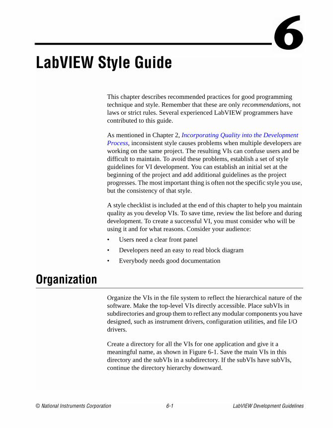
© National Instruments Corporation 6-1 LabVIEW Development Guidelines
6LabVIEW Style Guide
This chapter describes recommended practices for good programmingtechnique and style. Remember that these are only recommendations, notlaws or strict rules. Several experienced LabVIEW programmers havecontributed to this guide.
As mentioned in Chapter 2, Incorporating Quality into the DevelopmentProcess, inconsistent style causes problems when multiple developers areworking on the same project. The resulting VIs can confuse users and bedifficult to maintain. To avoid these problems, establish a set of styleguidelines for VI development. You can establish an initial set at thebeginning of the project and add additional guidelines as the projectprogresses. The most important thing is often not the specific style you use,but the consistency of that style.
A style checklist is included at the end of this chapter to help you maintainquality as you develop VIs. To save time, review the list before and duringdevelopment. To create a successful VI, you must consider who will beusing it and for what reasons. Consider your audience:
• Users need a clear front panel
• Developers need an easy to read block diagram
• Everybody needs good documentation
OrganizationOrganize the VIs in the file system to reflect the hierarchical nature of thesoftware. Make the top-level VIs directly accessible. Place subVIs insubdirectories and group them to reflect any modular components you havedesigned, such as instrument drivers, configuration utilities, and file I/Odrivers.
Create a directory for all the VIs for one application and give it ameaningful name, as shown in Figure 6-1. Save the main VIs in thisdirectory and the subVIs in a subdirectory. If the subVIs have subVIs,continue the directory hierarchy downward.
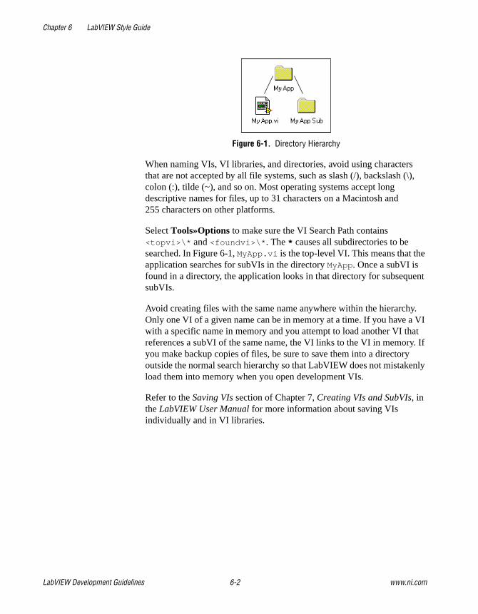
Chapter 6 LabVIEW Style Guide
LabVIEW Development Guidelines 6-2 www.ni.com
Figure 6-1. Directory Hierarchy
When naming VIs, VI libraries, and directories, avoid using charactersthat are not accepted by all file systems, such as slash (/), backslash (\),colon (:), tilde (~), and so on. Most operating systems accept longdescriptive names for files, up to 31 characters on a Macintosh and255 characters on other platforms.
Select Tools»Options to make sure the VI Search Path contains<topvi>\* and <foundvi>\*. The * causes all subdirectories to besearched. In Figure 6-1, MyApp.vi is the top-level VI. This means that theapplication searches for subVIs in the directory MyApp. Once a subVI isfound in a directory, the application looks in that directory for subsequentsubVIs.
Avoid creating files with the same name anywhere within the hierarchy.Only one VI of a given name can be in memory at a time. If you have a VIwith a specific name in memory and you attempt to load another VI thatreferences a subVI of the same name, the VI links to the VI in memory. Ifyou make backup copies of files, be sure to save them into a directoryoutside the normal search hierarchy so that LabVIEW does not mistakenlyload them into memory when you open development VIs.
Refer to the Saving VIs section of Chapter 7, Creating VIs and SubVIs, inthe LabVIEW User Manual for more information about saving VIsindividually and in VI libraries.
Chapter 6 LabVIEW Style Guide
© National Instruments Corporation 6-3 LabVIEW Development Guidelines
Front Panel StyleRemember that a user’s first contact with your work is the front panel.Front panels should be well organized and easy to use.
Fonts and Text StylesDo not be tempted to use all the fonts and styles available. Limit the VI tothe three standard fonts—application, system, and dialog—unless you havea specific reason to use a different font. For example, monospace fonts,fonts that are proportionally spaced, are useful for string controls andindicators where the number of characters is critical. To set the default font,select it from the Text Settings pull-down menu in the toolbar without anytext or objects selected. You can select all the labels you need to change andset the font in all of them at once using the Text Settings pull-down menu.
The actual font used for the three standard fonts varies depending on theplatform. For example, when working under Windows, preferences andvideo driver settings will affect the size of the fonts. Text might appearlarger or smaller on different systems, depending on these factors. Tocompensate for this, allow extra space for larger fonts and enable the Sizeto Text option on the shortcut menu. Use carriage returns to make multilinetext instead of resizing the text frame.
You can prevent labels from overlapping because of font changes onmultiple platforms by allowing extra space between controls. For example,make space to the right of text that has been left-justified. Fonts are the leastportable aspect of the front panel, so always test them on all of the targetplatforms.
ColorLike fonts, it is easy to get carried away with color. The particular dangerof color is that it distracts the operator from important information. Forinstance, a yellow, green, and bright orange background make it difficult tosee a red danger light. Another problem is that other platforms might nothave as many colors available. Also, some users have black-and-whitemonitors that cannot display certain color combinations well. For example,black-and-white monitors display black letters on a red background as allblack. Use a minimal number of colors, emphasizing black, white, andgray. The following are some simple guidelines for using color:
• Never use color as the sole indicator of device state. People with somedegree of color-blindness might not detect the change. Also, multiplotgraphs and charts can lose meaning when displayed in black and white.
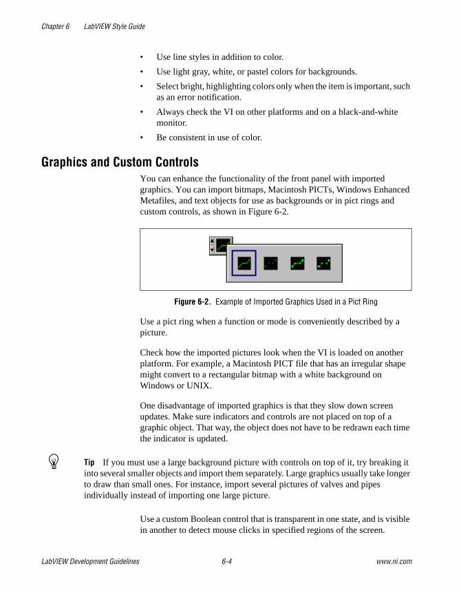
Chapter 6 LabVIEW Style Guide
LabVIEW Development Guidelines 6-4 www.ni.com
• Use line styles in addition to color.
• Use light gray, white, or pastel colors for backgrounds.
• Select bright, highlighting colors only when the item is important, suchas an error notification.
• Always check the VI on other platforms and on a black-and-whitemonitor.
• Be consistent in use of color.
Graphics and Custom ControlsYou can enhance the functionality of the front panel with importedgraphics. You can import bitmaps, Macintosh PICTs, Windows EnhancedMetafiles, and text objects for use as backgrounds or in pict rings andcustom controls, as shown in Figure 6-2.
Figure 6-2. Example of Imported Graphics Used in a Pict Ring
Use a pict ring when a function or mode is conveniently described by apicture.
Check how the imported pictures look when the VI is loaded on anotherplatform. For example, a Macintosh PICT file that has an irregular shapemight convert to a rectangular bitmap with a white background onWindows or UNIX.
One disadvantage of imported graphics is that they slow down screenupdates. Make sure indicators and controls are not placed on top of agraphic object. That way, the object does not have to be redrawn each timethe indicator is updated.
Tip If you must use a large background picture with controls on top of it, try breaking itinto several smaller objects and import them separately. Large graphics usually take longerto draw than small ones. For instance, import several pictures of valves and pipesindividually instead of importing one large picture.
Use a custom Boolean control that is transparent in one state, and is visiblein another to detect mouse clicks in specified regions of the screen.

Chapter 6 LabVIEW Style Guide
© National Instruments Corporation 6-5 LabVIEW Development Guidelines
LayoutConsider the arrangement of controls on front panels. Keep front panelssimple to avoid confusing the user, and use menus to help reduce clutter.For top-level VIs that users see, place the most important controls in themost prominent positions. Use the Align Objects and the DistributeObjects pull-down menus to create a uniform layout. Use Edit»ReorderControls in Panel to arrange controls in a logical sequence.
Do not overlap controls with other controls or with their own label, digitaldisplay, or other parts unless you are trying to achieve a special effect.Overlapped controls are much slower to draw and might flash.
Use decorations such as raised rectangles or recessed frames to visuallygroup objects with related functions, as shown in the illustration below. Useclusters to group related data. However, do not use clusters for aestheticpurposes only. It makes connections to the VI more difficult to understand.Avoid importing graphic objects that are inanimate copies of real controls.For instance, do not use a copy of a cluster border to group controls that arenot actually in a cluster.
Figure 6-3. Example of Using Decorations to Visually Group Objects Together
For subVI front panels the user does not see, you can place the objects sothey correspond to the connector pattern. Generally, place inputs on the leftand outputs on the right.
Sizing and PositioningFront panels should fit on a monitor that is the standard resolution for mostintended users. Make the window as small as possible without crowdingcontrols or sacrificing a good layout. If the VIs are intended for in-houseuse and everyone is using high-resolution display settings, design large
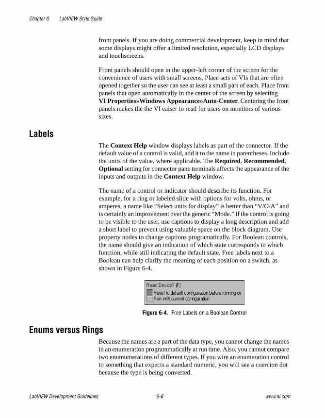
Chapter 6 LabVIEW Style Guide
LabVIEW Development Guidelines 6-6 www.ni.com
front panels. If you are doing commercial development, keep in mind thatsome displays might offer a limited resolution, especially LCD displaysand touchscreens.
Front panels should open in the upper-left corner of the screen for theconvenience of users with small screens. Place sets of VIs that are oftenopened together so the user can see at least a small part of each. Place frontpanels that open automatically in the center of the screen by selectingVI Properties»Windows Appearance»Auto-Center. Centering the frontpanels makes the the VI eaiser to read for users on monitors of varioussizes.
LabelsThe Context Help window displays labels as part of the connector. If thedefault value of a control is valid, add it to the name in parentheses. Includethe units of the value, where applicable. The Required, Recommended,Optional setting for connector pane terminals affects the appearance of theinputs and outputs in the Context Help window.
The name of a control or indicator should describe its function. Forexample, for a ring or labeled slide with options for volts, ohms, oramperes, a name like “Select units for display” is better than “V/O/A” andis certainly an improvement over the generic “Mode.” If the control is goingto be visible to the user, use captions to display a long description and adda short label to prevent using valuable space on the block diagram. Useproperty nodes to change captions programatically. For Boolean controls,the name should give an indication of which state corresponds to whichfunction, while still indicating the default state. Free labels next to aBoolean can help clarify the meaning of each position on a switch, asshown in Figure 6-4.
Figure 6-4. Free Labels on a Boolean Control
Enums versus RingsBecause the names are a part of the data type, you cannot change the namesin an enumeration programmatically at run time. Also, you cannot comparetwo enumumerations of different types. If you wire an enumeration controlto something that expects a standard numeric, you will see a coercion dotbecause the type is being converted.
Chapter 6 LabVIEW Style Guide
© National Instruments Corporation 6-7 LabVIEW Development Guidelines
Enumeration controls are useful for making code easier to read. Ringcontrols are useful for front panels the user interacts with, where you wantto programmatically change the strings.
Default Values and RangesExpect the user to supply invalid values to every control. You can check forinvalid values in the block diagram or right-click the control and selectData Range to set the control item to coerce values into the desired range:Minimum, Maximum, and Increment.
Set controls with reasonable default values. A VI should not fail when runwith default values. Remember to show the default in parentheses in thecontrol label. Do not set default values of indicators like graphs, arrays, andstrings without a good reason because that wastes disk space when savingthe VI.
Use default values intelligently. In the case of high-level file VIs such as theWrite Characters to File VI, the default is an empty path that forces the VIto display a File Selection dialog box. This can save the use of a Booleanswitch in many cases.
Other difficult situations must be dealt with programmatically. Many GPIBinstruments limit the permissible settings of one control based on thesettings of another. For example, a voltmeter might permit a range settingof 2,000 V for DC but only 1,000 V for AC. If the affected controls likeRange and Mode reside in the same VI, place the interlock logic there. Ifone or more of the controls are not readily available, you can request thepresent settings from the instrument to ensure you do not try to set aninvalid combination.
Property NodesUse property nodes to give the user more feedback on the front panel andto make the VI easier to use. The following are examples of using propertynodes to enhance ease of use:
• Set the text focus to the main, most commonly used control.
• Disable or hide controls that are not currently relevant or valid.
• Guide the user through steps by highlighting controls.
• Change window colors to bring attention to error conditions.
Chapter 6 LabVIEW Style Guide
LabVIEW Development Guidelines 6-8 www.ni.com
Key NavigationSome users prefer to use the keyboard instead of a mouse. In someenvironments, such as a manufacturing plant, only a keyboard is available.Even if a mouse is used, keyboard shortcuts, such as using the <Enter> key to select the default action of a dialog box, add convenience. For thesereasons, consider including keyboard shortcuts for the VIs.
Select Edit»Reorder Controls in Panel to see the order of the front panelcontrols. In general, set the order to read left to right and top to bottom.
Pay attention to the key navigation options for buttons on the front panel.You can set key navigation options by right-clicking any control andselecting Advanced»Key Navigation from the shortcut menu. Set the<Enter> key to be the keyboard shortcut to the front panel default control.However, if you have a multiline string control on the front panel, youmight not want to use the <Enter> key as a shortcut. Refer to theControlling Button Behavior with Key Navigation section of the LabVIEWUser Manual for more information about using key navigation options.
If the front panel has a Cancel button, assign a shortcut to the <Esc> key.You also can use function keys as navigation buttons to move from screento screen. If you do this, be sure to use the shortcuts consistently. Forcontrols that are offscreen, use the Key Navigation dialog box to skip overthe controls when tabbing.
Also, you might consider using the Key Focus property to set the focusprogrammatically to a specific control when the front panel opens.
Dialog BoxesDialog boxes can be used effectively in LabVIEW applications as a way togroup controls that are too numerous to place on one front panel. Considerusing the tab control to group controls effectively and reduce clutter.
Many modern programs use dialog boxes to announce messages to the user,but quite often this is overused. Consider using a status text window todisplay less serious warnings. Refer to the Designing Dialog Boxes sectionof Chapter 4, Building the Front Panel, of the LabVIEW User Manual formore information about creating dialog boxes.
Chapter 6 LabVIEW Style Guide
© National Instruments Corporation 6-9 LabVIEW Development Guidelines
Block Diagram StyleStyle is just as important on the block diagram of the VI as the front panel.Users may not see it, but other developers will. A well-planned, consistentblock diagram is easier to understand and modify.
Good Wiring TechniquesThe block diagram is the primary way for others to understand how a VIworks, therefore it is often worth the effort to follow a few simple steps tomake the block diagrams more organized and easier to read. The Align andDistribute feature in LabVIEW can make it easy to quickly arrange objectson the block diagram to make it easier to see and understand groupings ofobjects. Placing objects using symmetry and straight lines can make theblock diagram easier to read.
Some other good wiring tips are:
• Avoid placing any wires under any block diagram objects such assubVIs or structures.
• Add as few bends in the wires as possible while trying to keep the wiresshort. Avoid creating wires with long complicated paths that can beconfusing.
• Delete any extraneous wires to keep block diagram clean.
• Avoid the use of local variables when it is possible to pass the data bywire. Every local variable that reads the data makes a copy of it.
• Try not to pass wires though structures if the data in the wire itself isnot used within the structure.
• Evenly space parallel wires in straight lines and around corners.
Memory and Speed OptimizationThere are many things you can do to optimize usage and execution time ofa LabVIEW VI. Generally an advanced topic, optimization quicklybecomes a concern when a program has large arrays and/or critical timingproblems. Refer to the LabVIEW Performance application note for moreinformation about optimizing LabVIEW VIs. Even though optimizationcan be a very involved topic, you can take the following basic actions tooptimize an application:
• If speed is not necessary to a While Loop, add a Wait function to avoidthe problem of slowing down other tasks. Generally slowing downother tasks is only an issue with loops that are not as active betweeniterations, such as the user interface loops, because LabVIEW runs the
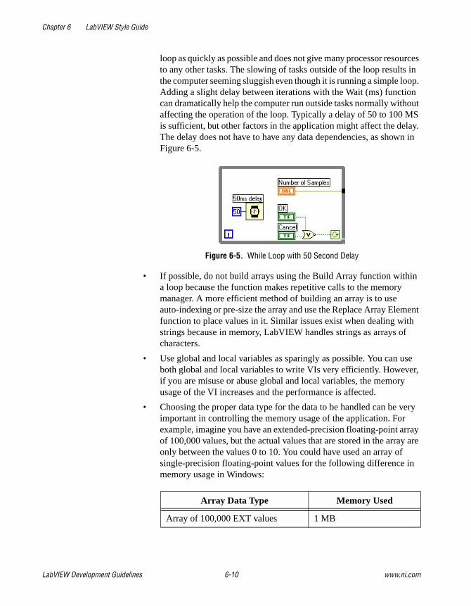
Chapter 6 LabVIEW Style Guide
LabVIEW Development Guidelines 6-10 www.ni.com
loop as quickly as possible and does not give many processor resourcesto any other tasks. The slowing of tasks outside of the loop results inthe computer seeming sluggish even though it is running a simple loop.Adding a slight delay between iterations with the Wait (ms) functioncan dramatically help the computer run outside tasks normally withoutaffecting the operation of the loop. Typically a delay of 50 to 100 MSis sufficient, but other factors in the application might affect the delay.The delay does not have to have any data dependencies, as shown inFigure 6-5.
Figure 6-5. While Loop with 50 Second Delay
• If possible, do not build arrays using the Build Array function withina loop because the function makes repetitive calls to the memorymanager. A more efficient method of building an array is to useauto-indexing or pre-size the array and use the Replace Array Elementfunction to place values in it. Similar issues exist when dealing withstrings because in memory, LabVIEW handles strings as arrays ofcharacters.
• Use global and local variables as sparingly as possible. You can useboth global and local variables to write VIs very efficiently. However,if you are misuse or abuse global and local variables, the memoryusage of the VI increases and the performance is affected.
• Choosing the proper data type for the data to be handled can be veryimportant in controlling the memory usage of the application. Forexample, imagine you have an extended-precision floating-point arrayof 100,000 values, but the actual values that are stored in the array areonly between the values 0 to 10. You could have used an array ofsingle-precision floating-point values for the following difference inmemory usage in Windows:
Array Data Type Memory Used
Array of 100,000 EXT values 1 MB
Chapter 6 LabVIEW Style Guide
© National Instruments Corporation 6-11 LabVIEW Development Guidelines
• Avoiding coercion dots also can help you reduce unnecessary memoryusage and speed. Coercion dots indicate that a conversion is takingplace from one data type to another, which means that a copy of thedata must be made. The effects of this become much more dramaticwhen there is coercion on large arrays of data.
• Consider indicator overhead when designing the VI if performance is aconcern for the application. Frequently updating front panel indicatorswith new data can effect the performance of the VI especially if youare displaying large amounts of data in graphs or charts. To optimizethe performance of the VI, only display the necessary information onthe front panel and only send data to indicators if the data is differentfrom what is already displayed.
Sizing and PositioningThe size of the block diagram window can affect how readable yourLabVIEW code is to others. In general, try to make the block diagramwindow no larger than the screen size. To ensure that the block diagram isreadable, keep it smaller than 800 × 600 pixels. While it is good to be awareof the size of the block diagram window, it is also very important to ensurethat the LabVIEW code that is displayed in it is not too large. Code that ismuch larger than the window displaying it can force others to scroll thewindow, sometimes making the code harder to read. Code that requires theuser to scroll only horizontally or vertically is acceptable as long as the userdoes not have to scroll an unreasonable amount to view the entire code.
Left-to-Right LayoutsLabVIEW was designed to use a left-to-right and sometimes top-to-bottomlayout. Block diagrams should follow this convention. While the positionsof program elements do not determine execution order, avoid wiring fromright to left. Only wires and structures determine execution order.
Block Diagram CommentsDevelopers who maintain and modify VIs need good documentation.Without it, modifying the code is more time-consuming and error-pronethan necessary.
Array of 100,000 SGL values 400 KB
Memory saved 600 KB
Array Data Type Memory Used

Chapter 6 LabVIEW Style Guide
LabVIEW Development Guidelines 6-12 www.ni.com
• Use comments on the block diagrams to explain what the code isdoing. LabVIEW code is not self-documenting even though it isgraphical. Free labels with a colored background work well for blockdiagram comments.
• Omit labels on function and subVI calls because they tend to be largeand unwieldy. Someone looking at the blcok diagram can easily findout the name of a function or subVI call by using the Context Helpwindow.
• Use free labels on wires to identify their use. This is particularly usefulfor wires coming from shift registers.
• Use labels on structures to specify the main functionality of thatstructure.
• Use labels on constants to specify the nature of the constant.
• Use labels on Call Library Nodes to specify what function the node iscalling.
• Use the description of Code Interface Nodes (CINs) to record thefollowing information:
– Source code title and filename
– Platform and O/S
– Compiler version
– Where to find the source code
– What the code does
– List of other files required by the CIN
– Other critical information required to maintain the CIN
• Use comments to document algorithms that you use on the blockdiagrams. If you use an algorithm from a book or other reference,provide the reference information.
Icon and Connector StyleUsing good style techniques when creating the icons and connectors forVIs can greatly benefit users of those VIs.
For examples of good icons and connector designs, the LabVIEW QueueVIs, available on Functions»Advanced»Synchronization»Queue palette.

Chapter 6 LabVIEW Style Guide
© National Instruments Corporation 6-13 LabVIEW Development Guidelines
IconThe icon represents the VI on a palette and the block diagram. Use thefollwoing suggestions when creating icons:
• Create a meaningful icon for every VI. The LabVIEW libraries are fullof well-designed icons that try to show the functionality of theunderlying program; use them as prototypes where applicable. Whenyou don’t have a picture, text is acceptable.
Tip 8pt Small Fonts is a good size and font choice for text icons
• Create a unified icon style for related VIs. This helps users visuallyunderstand what subVI calls are associated with the top-level VI.
• Do not use plays on words when making the icon. Plays on wordsusually do not work for users who speak a different language. Forexample, don't represent the data logging VI by a picture of a piece ofa tree branch or a lumberjack. This sort of picture does nottranslate well.
• Always create a black and white icon for printing purposes. Probablynot every user has access to a nice color printer.
• Always create standard size (32x32) icons. VIs with smaller icons canbe awkward to select and wire. They also tend to look strange whenwired.
Figure 6-6. Example: Queue VIs
The Queue VIs use a picture (a graphical representation of a queue) as acommon element in their icons to unify the icon designs. Notice that all ofthe icons use pictures only (and none that are plays on words), making theseicons suitable for speakers of any language.
Refer to the Creating an Icon section of the LabVIEW User Manual formore information about using icons.
Chapter 6 LabVIEW Style Guide
LabVIEW Development Guidelines 6-14 www.ni.com
Connector
The connector has terminals that connect to the controls and indicators ofthe subVIs of the top-level VI. Use the following suggestions when creatingconnectors:
• Always select a connector pane pattern with extra terminals.Unforeseen additions to the VI may require more terminals. Changingpatterns requires relinking to the subVI in all calling VIs and mayresult in wiring incompatibilities.
• Choose the same connector pane pattern for related VIs. Wire relatedinputs and outputs on opposite terminals .
• Wire inputs on the left and outputs on the right to follow the standardleft-to-right data flow.
• Use the Required, Recommended, Optional setting for everyterminal.
• Choose only connector pane patterns with 16 or fewer terminals.While patterns with more terminals might seem useful, they are verydifficult to wire. If you need to pass more data, use clusters.
• Strive for similar arrangements between panel and connector panelayouts.
Style ChecklistUse the following checklist to help you maintain consistent style andquality. You might want to copy this checklist to use on all LabVIEWprojects.
VI Checklist❑ Organize VIs in a hierarchical directory with easily accessible
top-level VIs and subVIs in subdirectories.
❑ Avoid putting too many VIs in one library because large LLBs takelonger to save.
❑ With LLBs, use Tools»Edit VI Library to mark top-level VIs.
❑ If the VIs will be used as subVIs, create a .mnu file or edit the menuthat is part of the LLB. Be sure to arrange the palettes, name the menus,and hide dependent subVIs.
Chapter 6 LabVIEW Style Guide
© National Instruments Corporation 6-15 LabVIEW Development Guidelines
❑ Give VI meaningful names without special characters, such asbackslash (\), slash (/), colon (:), and tilde (~).
❑ Use standard extensions so Windows and UNIX can distinguish files(.vi, .ctl).
❑ Capitalize first letters of VI names.
❑ Distinguish example VIs, top-level VIs, subVIs, controls, and globalvariables by saving them in subdirectories, separate libraries in thesame directory, or by giving them descriptive names such asMainX.vi, Example of X.vi, Global X.vi, andTypeDef X.ctl.
❑ Write a VI description. Proofread it. Check the Context Help window.
❑ Include your name and/or company and the date in the VI Descriptionon the Documentation page of the VI Properties dialog box.
❑ When you modify a VI, use the History window to document thechanges.
❑ Create a meaningful black-and-white icon in addition to a color icon.
❑ Choose a connector pane pattern to leave extra terminals for laterdevelopment. Use consistent layout across related VIs.
❑ Avoid using connector panes with more than 16 terminals.
❑ Consider VI and window options carefully.
❑ Hiding menu bars and using dialog box style makes Context Help andVI descriptions inaccessible.
❑ Hiding Abort and debugging buttons increases performance slightly.
❑ Set print options to print attractive output in the most useful format.
❑ Make test VIs that check error conditions, invalid values, and Cancelbuttons.
❑ Save test VIs in a separate directory so you can reuse them.
❑ Load and test VIs on multiple platforms, making sure labels fit andwindow size and position are correct.
Chapter 6 LabVIEW Style Guide
LabVIEW Development Guidelines 6-16 www.ni.com
Front Panel Checklist❑ Give controls meaningful names. Use consistent capitalization.
❑ Make name label backgrounds transparent.
❑ Check for consistent placement of control names.
❑ Use standard, consistent fonts throughout all front panels.
❑ Use Size to Text for all text for portability and add carriage returns ifnecessary.
❑ Use Required, Recommended, and Optional settings on theconnector pane.
❑ Put default values in parentheses after input names.
❑ Include unit information in names if applicable, for example, TimeLimit (10 Seconds).
❑ Write descriptions for controls, including array, cluster, and refnumelements. Remember that you might need to change the descriptionif you copy the control.
❑ Arrange controls logically. For top-level VIs, put the most importantcontrols in the most prominent positions. For subVIs, put inputs on theleft and outputs on the right and follow connector pane terminals.
❑ Arrange controls attractively, using the Align Objects and theDistribute Objects pull-down menus.
❑ Do not overlap controls.
❑ Use color logically and sparingly, if at all.
❑ Use error in and error out clusters where appropriate.
❑ Consider other common thread controls, such as taskID, refnum,and name.
❑ Provide a Stop button if necessary. Do not use the Abort button to stopa VI. Hide the Abort button.
❑ Use ring controls and enumerated controls where appropriate. If youare using a Boolean controls for two options, consider using anenumerated control instead to allow for future expansion of options.
Chapter 6 LabVIEW Style Guide
© National Instruments Corporation 6-17 LabVIEW Development Guidelines
❑ Use custom controls or typedefs for common controls, especially forrings and enums.
❑ In system controls, label controls with the same name as the VI, forexample, Alarm Boolean.ctl has the default name Alarm Boolean.
Block Diagram Checklist❑ Avoid creating extremely large block diagrams. Limit the scrolling
necessary to see in the entire block diagram to one direction.
❑ Label controls, important functions, constants, property nodes, localvariables, global variables, and structures.
❑ Add comments. Use object labels instead of free labels whereapplicable and scrollable string constants for long comments.
❑ Place labels below objects when possible and right-justify text if labelis placed to the left of an object.
❑ Use standard, consistent font conventions throughout.
❑ Use Size to Text for all text and add carriage returns if necessary.
❑ Reduce white space in smaller block diagrams but allow at least 3 or4 pixels between objects.
❑ Flow data from left to right. Wires enter from the left and exit to theright, not the top or the bottom.
❑ Align and distribute functions, terminals, and constants.
❑ Label long wires with small labels with white backgrounds.
❑ Do not wire behind objects.
❑ Make good use of reusable, testable subVIs.
❑ Make sure the program can deal with error conditions and invalidvalues.
❑ Show name of source code or include source code for any CINs.
❑ Save with the most important or the first frame of structures showing.
❑ Review for efficiency, especially data copying, and accuracy,especially parts without data dependency.
© National Instruments Corporation A-1 LabVIEW Development Guidelines
AReferences
This appendix provides a list of references for further information aboutsoftware engineering concepts.
LabVIEW Technical Resource. Edited by Lynda P. Gruggett, LTRPublishing, phone (214) 706-0587, fax (214) 706-0506.http://www.LTRPub.com. A quarterly newsletter and disk of VIs thatfeatures technical articles about all aspects of LabVIEW.
Rapid Development: Taming Wild Software Schedules. Steve C.McConnell, Microsoft Press. Explanation of software engineeringpractices with many examples and practical suggestions.
Microsoft Secrets. Michael A. Cusumano and Richard W. Selby, Free Press.In-depth examination of the programming practices Microsoft uses.Contains interesting discussions of what Microsoft has done right and whatit has done wrong. Includes a good discussion of team organization,scheduling, and milestones.
Dynamics of Software Development. Jim McCarthy, Microsoft Press.Another look at what has worked and what has not for developers atMicrosoft. This book is written by a developer from Microsoft and containsnumerous real-world stories that help bring problems and solutions intofocus.
Software Engineering—A Practitioner’s Approach. Roger S. Pressman,McGraw-Hill Inc. A detailed survey of software engineering techniqueswith descriptions of estimation techniques, testing approaches, and qualitycontrol techniques.
Handbook of Walkthroughs, Inspections, and Technical Reviews:Evaluating Programs, Projects, and Products. Daniel P. Freedmanand Gerald M. Weinberg, Dorset House Publishing Co., Inc. A discussionof how to conduct design and code reviews with many examples of thingsto look for and the best practices to follow during a review.
ISO 9000.3: A Tool for Software Product and Process Improvement.Raymond Kehoe and Alka Jarvis, Springer-Verlag New York, Inc.

Appendix A References
LabVIEW Development Guidelines A-2 www.ni.com
Describes what is expected by ISO 9001 in conjunction with ISO 9000.3and provides templates for documentation.
Software Engineering Economics. Barry W. Boehm, Prentice-Hall.Description of the wideband delphi and COCOMO estimation techniques.
Software Engineering. Edited by Merlin Dorfman and Richard Thayer,IEEE Computer Science Press. Collection of articles on a variety ofsoftware engineering topics, including a discussion of the spiral life cyclemodel by Barry W. Boehm.
© National Instruments Corporation B-1 LabVIEW Development Guidelines
BTechnical Support Resources
Web SupportNational Instruments Web support is your first stop for help in solvinginstallation, configuration, and application problems and questions. Onlineproblem-solving and diagnostic resources include frequently askedquestions, knowledge bases, product-specific troubleshooting wizards,manuals, drivers, software updates, and more. Web support is availablethrough the Technical Support section of www.ni.com
NI Developer ZoneThe NI Developer Zone at zone.ni.com is the essential resource forbuilding measurement and automation systems. At the NI Developer Zone,you can easily access the latest example programs, system configurators,tutorials, technical news, as well as a community of developers ready toshare their own techniques.
Customer EducationNational Instruments provides a number of alternatives to satisfy yourtraining needs, from self-paced tutorials, videos, and interactive CDs toinstructor-led hands-on courses at locations around the world. Visit theCustomer Education section of www.ni.com for online course schedules,syllabi, training centers, and class registration.
System IntegrationIf you have time constraints, limited in-house technical resources, or otherdilemmas, you may prefer to employ consulting or system integrationservices. You can rely on the expertise available through our worldwidenetwork of Alliance Program members. To find out more about ourAlliance system integration solutions, visit the System Integration sectionof www.ni.com

Appendix B Technical Support Resources
LabVIEW Development Guidelines B-2 www.ni.com
Worldwide SupportNational Instruments has offices located around the world to help addressyour support needs. You can access our branch office Web sites from theWorldwide Offices section of www.ni.com. Branch office web sitesprovide up-to-date contact information, support phone numbers, e-mailaddresses, and current events.
If you have searched the technical support resources on our Web site andstill cannot find the answers you need, contact your local office or NationalInstruments corporate. Phone numbers for our worldwide offices are listedat the front of this manual.
© National Instruments Corporation G-1 LabVIEW Development Guidelines
Glossary
B
black box testing A form of testing where a module is tested without knowing how themodule is implemented. The module is treated as if it were a black box thatyou cannot look inside. Instead, you generate tests to verify the modulebehaves the way it is supposed to according to the requirementsspecification.
C
Capability MaturityModel (CMM)
A model for judging the maturity of the processes of an organization andfor identifying the key practices that are required to increase the maturityof these processes. The Software CMM (SW-CMM) has become a de factostandard for assessing and improving software processes. Through theSW-CMM, the Software Engineering Institute and software developmentcommunity have put in place an effective means for modeling, defining,and measuring the maturity of the processes software professionals use.
COCOMO Estimation COnstructive COst MOdel. A formula-based estimation method forconverting software size estimates to estimated development time.
code and fix model A lifecycle model that involves developing code with little or no planning,and fixing problems as they arise.
configurationmanagement
A mechanism for controlling changes to source code, documents, and othermaterials that make up a product. During software development, SourceCode Control is a form of configuration management: Changes occur onlythrough the Source Code Control mechanism. It is also common toimplement release configuration management to ensure a particular releaseof software can be rebuilt, if necessary. This implies archival developmentof tools, source code, and so on.
F
Function-PointEstimation
A formula-based estimation method applied to a category breakdown ofproject requirements.
Glossary
LabVIEW Development Guidelines G-2 www.ni.com
I
integration testing Integration testing assures that individual components work togethercorrectly. Such testing may uncover, for example, a misunderstanding ofthe interface between modules.
L
lifecycle model A model for software development, including steps to follow from theinitial concept through the release, maintenance, and upgrading of thesoftware.
S
Software EngineeringInstitute (SEI)
A federally funded research and development center chartered to studysoftware engineering technology. The SEI is located at Carnegie MellonUniversity and is sponsored by the Defense Advanced Research ProjectsAgency.
source lines of code The measure of the number of lines of code that make up a project. It is usedin some organizations to measure the complexity and cost of a project. Howthe lines are counted depends on the organization. For example, someorganizations do not count blank lines and comment lines. Some countC lines, and some count only the final assembly language lines.
spiral model A lifecycle model that emphasizes risk management through a series ofiterations in which risks are identified, evaluated, handled.
system testing System testing begins after integration testing is complete. System testingassures that all the individual components function correctly together andconstitute a product that meets the intended requirements. This stage oftenuncovers performance, resource usage, and other problems.
U
unit testing Testing only a single component of a system, in isolation from the rest ofthe system. Unit testing occurs before the module is incorporated into therest of the system.

Glossary
© National Instruments Corporation G-3 LabVIEW Development Guidelines
W
waterfall model A lifecycle model that consists of several non-overlapping stages,beginning with the software concept and continuing through testing andmaintenance.
white box testing Unlike black box testing, white box testing creates tests that take intoaccount the particular implementation of the module. For example, whitebox testing is used to verify all the paths of execution of the module havebeen exercised.
wideband delphiestimation
Wideband delphi is a technique used by a group to estimate the amount ofeffort a particular project will take.
© National Instruments Corporation I-1 LabVIEW Development Guidelines
Index
Aalpha testing, 2-9
Bbeta testing, 2-9bibliography, A-1black box testing, 2-6block diagram
checklist, 6-17comments, 6-11left-to-right layouts, 6-11memory and speed optimization, 6-9sizing and positioning, 6-11style considerations, 6-9top-down design, 3-2wiring techniques, 6-9
bottom-up design, 3-6Build Array function, avoiding, 6-10
CCapability Maturity Model (CMM)
standards, 2-14change control. See configuration management.CINs, documenting, 6-12CMM (Capability Maturity Model)
standards, 2-14COCOMO (Constructive Cost Model)
estimation, 4-6code and fix model, 1-4Code Interface Nodes, documenting, 6-12code walkthroughs, 2-11coercion dots, avoiding, 6-11color style guidelines, 6-3comments, in block diagrams, 6-11common operations, identifying, 3-11
configuration management, 2-2change control, 2-4definition, 2-2managing project-related files, 2-3retrieving old versions of files, 2-3source code control, 2-2tracking changes, 2-4
connector pane style considerations, 6-14Constructive Cost Model (COCOMO)
estimation, 4-6controls and indicators
color, 6-3default values and ranges, 6-7descriptions, as documentation, 5-4dialog boxes, 6-8enumerations vs. rings, 6-6font and text styles, 6-3graphics and custom controls, 6-4keyboard navigation, 6-8labels, 6-6layout, 6-5performance considerations, 6-9property nodes, 6-7sizing and positioning, 6-5style considerations, 6-3
conventions used in manual, ixcustom controls and graphics, 6-4Customer Education, B-1
Ddata acquisition system design example, 3-3data types, choosing, 6-10decorations, for visual grouping of objects, 6-5default values for controls, 6-7design reviews, 2-11
Index
LabVIEW Development Guidelines I-2 www.ni.com
design techniques, 3-1. See also developmentmodels.
bottom-up design, 3-6data acquisition system (example), 3-3defining requirements for application, 3-1front panel prototyping, 3-9identifying common operations, 3-11instrument driver (example), 3-7multiple developer considerations, 3-8performance benchmarking, 3-10top-down design, 3-2
design-related documentation, 5-1development models, 1-1. See also design
techniques; prototyping.code and fix model, 1-4common pitfalls, 1-1lifecycle models, 1-4modified waterfall model, 1-7prototyping for clarification, 1-7spiral model, 1-9waterfall model, 1-5
dialog boxes for front panels, 6-8directories
naming, 6-1style considerations, 6-2VI search path, 6-2
documentation for LabVIEW DevelopmentGuidelines
conventions used in manual, ixreferences, A-1related documentation, x
documentation of applications, 5-1design-related documentation, 5-1help files, 5-3LabVIEW features, 5-2overview, 5-1user documentation, 5-2
application documentation, 5-3library of VIs, 5-2
VI and control descriptions, 5-4control and indicator
descriptions, 5-5self-documenting front panels, 5-4VI description, 5-4
Eeffort estimation, 4-4. See also estimation.enumerations vs. rings, 6-6estimation, 4-1
COCOMO estimation, 4-6effort estimation, 4-4feature creep, 4-1function point estimation, 4-5mapping estimates to schedules, 4-6overview, 4-1problems with size-based metrics, 4-3source lines of code/number of nodes, 4-2wideband delphi estimation, 4-4
FFDA (U.S. Food & Drug Administration)
standards, 2-14feature creep, 4-1file management
change control, 2-4managing project-related files, 2-3previous versions of files, 2-3tracking changes, 2-4
filenames for directories, VI libraries, andVIs, 6-2
font style guidelines, 6-3Food & Drug Administration (FDA)
standards, 2-14front panels
color, 6-3default values and ranges, 6-7dialog boxes, 6-8enumerations vs. rings, 6-6
Index
© National Instruments Corporation I-3 LabVIEW Development Guidelines
fonts and text styles, 6-3graphics and custom controls, 6-4keyboard navigation, 6-8labels, 6-6layout, 6-5property nodes, 6-7prototyping, 3-9self-documenting, 5-4sizing and positioning, 6-5style checklist, 6-16style considerations, 6-3
function point estimation, 4-5
Gglobal variables, avoiding, 6-10graphics and custom controls, 6-4
Hhelp files
creating, 5-3help compilers, 5-3linking to VIs, 5-4
hierarchical organization of files, 6-1directories (folders), 6-1naming VIs, VI libraries, and
directories, 6-2History window, 5-2
Iicon style considerations, 6-13IEEE (Institute of Electrical and Electronic
Engineers) standards, 2-16indicators. See controls and indicators.Institute of Electrical and Electronic Engineers
(IEEE) standards, 2-16instrument driver design example, 3-7integration testing, 2-8
International Organization for Standards(ISO) 9000, 2-13
Kkeyboard navigation, 6-8
Llabels
block diagram documentation, 6-11controls and indicators, 6-6font usage, 6-3
layout of front panels, 6-5left-to-right layouts, 6-11libraries. See VI libraries.lifecycle models, 1-4
code and fix model, 1-4definition, 1-4LabVIEW prototyping methods, 1-8modified waterfall model, 1-7prototyping, 1-7spiral model, 1-9waterfall model, 1-5
lines of code. See Source Lines of Codes(SLOCs) metric.
local variables, avoiding, 6-10
Mmanual. See documentation for LabVIEW
Development Guidelines.memory and speed optimization, 6-9metrics. See size-based metrics.milestones
responding to missed milestones, 4-7tracking schedules using milestones, 4-7
modified waterfall model, 1-7multiple developers, design
considerations, 3-8
Index
LabVIEW Development Guidelines I-4 www.ni.com
Nnaming VIs, VI libraries, and directories, 6-2National Instruments Web support, B-1NI Developer Zone, B-1nodes
definition, 4-2source lines of code/number of nodes
estimation, 4-2
Pperformance
benchmarking, 3-10memory and speed optimization, 6-9
positioning. See sizing and positioning.postmortem evaluation, 2-12Print dialog box, 5-2project tracking. See scheduling and project
tracking.property nodes, 6-7prototyping. See also design techniques.
development model, 1-7front panel prototyping, 3-9LabVIEW prototyping methods, 1-8
Qquality control, 2-1
code walkthroughs, 2-11configuration management, 2-2
change control, 2-4managing project-related files, 2-3retrieving old versions of files, 2-3source code control, 2-2tracking changes, 2-4
design reviews, 2-11postmortem evaluation, 2-12requirements, 2-1software quality standards, 2-13
CMM, 2-14FDA standards, 2-14
IEEE, 2-16ISO 9000, 2-13
style guidelines, 2-10testing guidelines, 2-5
black box and white box testing, 2-6formal methods of verification, 2-9integration testing, 2-8system testing, 2-9unit testing, 2-6
Rranges of values for controls, 6-7references, A-1rings vs. enumerations, 6-6risk management. See spiral model.
Ssafeguarding applications, 2-1. See also
quality control.scheduling and project tracking, 4-1
estimation, 4-1COCOMO estimation, 4-6effort estimation, 4-4function point estimation, 4-5problems with size-based
metrics, 4-3source lines of code/number of
nodes, 4-2wideband delphi estimation, 4-4
mapping estimates to schedules, 4-6tracking schedules using milestones, 4-7
missed milestones, 4-7size-based metrics
problems, 4-3source lines of codes/number of
nodes, 4-2sizing and positioning
block diagrams, 6-11front panels, 6-6
Index
© National Instruments Corporation I-5 LabVIEW Development Guidelines
SLOCs. See source lines of code (SLOCs)metric.
software quality standards, 2-13Capability Maturity Model (CMM), 2-14Institute of Electrical and Electronic
Engineers (IEEE), 2-16International Organization for
Standardization ISO 9000, 2-13U.S. Food and Drug Administration
(FDA), 2-14source code control tools
change control, 2-4managing project-related files, 2-3previous versions of files, 2-3purpose and use, 2-3quality control considerations, 2-2tracking changes, 2-4
source lines of code (SLOCs) metricin estimation, 4-2problems with, 4-3
speed and memory optimization, 6-9spiral model, 1-9standards. See software quality standards.stub VIs, 3-9style guidelines, 6-1
block diagram, 6-9left-to-right layouts, 6-11memory and speed optimization, 6-9sizing and positioning, 6-11wiring techniques, 6-9
connector panes, 6-14front panels, 6-3
color, 6-3default values and ranges, 6-7descriptions, 6-6enumerations vs. rings, 6-6fonts and text, 6-3graphics and custom controls, 6-4keyboard navigation, 6-8labels, 6-6layout, 6-5
property nodes, 6-7sizing and positioning, 6-5
hierarchical organization of files, 6-1directories (folders), 6-1naming VIs, VI libraries, and
directories, 6-2icons, 6-13inconsistent developer styles, 2-10style checklist, 6-14
block diagram, 6-17front panel, 6-16VIs, 6-14
subVI library, documenting, 5-2system integration, B-1system testing, 2-9
Ttechnical support resources, B-1testing guidelines, 2-5
black box and white box testing, 2-6formal methods of verification, 2-9integration testing, 2-8system testing, 2-9unit testing, 2-6
text style guidelines, 6-3top-down design, 3-2tracking changes, 2-4tracking projects. See scheduling and project
tracking.
Uunit testing, 2-6U.S. Food & Drug Administration (FDA)
standards, 2-14user documentation. See documentation of
applications.
Index
LabVIEW Development Guidelines I-6 www.ni.com
Vverification methods, 2-9. See also testing
guidelines.VI libraries
documenting, 5-2hierarchical organization, 6-1
VI Metrics tool, 4-2VI Search Path, 6-2VIs
description, as documentation, 5-4hierarchical organization, 6-1linking to help files, 5-4memory and speed optimization, 6-9style checklist, 6-14
WWait function, adding to While loops, 6-9waterfall model, 1-5
modified, 1-7Web support from National Instruments, B-1white box testing, 2-6wideband delphi estimation, 4-4wiring techniques, 6-9Worldwide technical support, B-2