Embed Size (px)
Citation preview
7HFKQRORJ\�3URILOH '(021675$7,21�352*5$0
7KH 6,7( 3URJUDP DVVHVVHV EXW GRHV QRW
DSSURYH RU HQGRUVH WHFKQRORJLHV�3DJH����
Cryogenic Barrier Insulation Plan
ARCTIC FOUNDATIONS, INC.(Cryogenic Barrier)
TECHNOLOGY DESCRIPTION: a temporary or permanent, long-term solution for
Long-term containment and immobilization of Buried hazardous waste may be totally confinedhazardous wastes using ground freezing by surrounding it with a frozen barrier. A frozentechnology is a relatively new field, even though barrier is created by reducing the groundground freezing has been used as a temporary temperature around the waste to the appropriateconstruction aid for several years. Ground freezing temperature and subsequently freezingfreezing is ideally suited to control waterborne the intervening waste. Artificial injection ofpollutants, since changing water from a liquid to water is usually unnecessary since moisture isa solid has an obvious immobilizing effect. The present in sufficient quantities in most soils. Thechallenge for conventional ground freezing ground freezing process is naturally suited totechnologies is to be technically and economically controlling hazardous waste because in-groundviable in the long-term. Arctic Foundations, Inc. moisture is transformed from serving as a(AFI), has developed a ground freezing potential waste mobilizing agent to serving as atechnology that can be used as protective agent.
containing and immobilizing hazardous wastes.
)HEUXDU\�����2QJRLQJ�3URMHFW
7KH 6,7( 3URJUDP DVVHVVHV EXW GRHV QRW
DSSURYH RU HQGRUVH WHFKQRORJLHV� 3DJH����
A typical containment system consists of multiple Experiment pond. The system’s effectiveness wasthermoprobes, an active (powered) condenser, an evaluated through the performance of ainterconnecting piping system, a two-phase working groundwater dye tracing investigation. Thefluid, and a control system. The thermoprobes demonstration was conducted in two phases.(AFI’s heat removal devices) and piping are Phase one included a background study that wasinserted into the soil at strategic locations around conducted to determine the presence of naturaland sometimes underneath the waste source fluorescence and existing dyes in groundwater atdepending on the presence or absence of a the site in order to select a nondetectable dye forconfining layer. Two-phase working fluid use during the dye tracing investigation.circulates through the piping and reduces thetemperature of the surrounding soil, creating a During phase two, the selected dye, Acid Red No.frozen barrier around the waste source. The 92, was injected into a standpipe located withinthermoprobes may be installed in any position and the confines of the frozen barrier. Water samplesspacing to create a frozen barrier wall of almost and charcoal packets were then collected atany required shape and size. The selection of predetermined sampling points outside the barrierworking fluids depends on the specific waste wall to determine the presence or absence of dyeapplication, site conditions, and desired soil in groundwater, springs, or seeps. The evaluationtemperatures, and may consist of freon, butane, of the technology under the SITE Program waspropane, carbon dioxide, or ammonia. completed in July 1998. Preliminary results from
WASTE APPLICABILITY:
The cryogenic barrier can provide subsurfacecontainment for a variety of sites and wastes, EPA PROJECT MANAGER:including the following: underground storage Steven Rocktanks; nuclear waste sites; plume control; burial U.S. EPAtrenches, pits, and ponds; in situ waste treatment National Risk Management Researchareas; chemically contaminated sites; and spent Laboratoryfuel storage ponds. The barrier is adaptable to 26 West Martin Luther King Driveany geometry; drilling technology presents the Cincinnati, OH 45268only constraint. 513-569-7149
STATUS:
The AFI cryogenic barrier system was accepted Ed Yarmakinto the SITE Demonstration Program in 1996. Arctic Foundations, Inc.The demonstration was conducted over a 5-month 5621 Arctic Blvd.period at the U.S. Department of Energy’s Oak Anchorage, AK 99518Ridge National Laboratory (ORNL) in Oak Ridge, 907-562-2741Tennessee in 1998. The demonstration was Fax: 907-562-0153conducted to evaluate the barrier’s ability tocontain radionuclides from the ORNL WasteArea Group ing 9 Homogeneous Reactor
the evaluation will be available in early 1999.
FOR FURTHER INFORMATION:
Fax: 513-569-7105
TECHNOLOGY DEVELOPER CONTACT:
RecoveryWell
CONTAMINATED SOIL
InjectionWell
Surfactant Flow
SurfactantTank
Oil andWater
Separator NAPL
Water/Surfactant
7HFKQRORJ\�3URILOH '(021675$7,21�352*5$0
7KH 6,7( 3URJUDP DVVHVVHV EXW GRHV QRW
DSSURYH RU HQGRUVH WHFKQRORJLHV�3DJH����
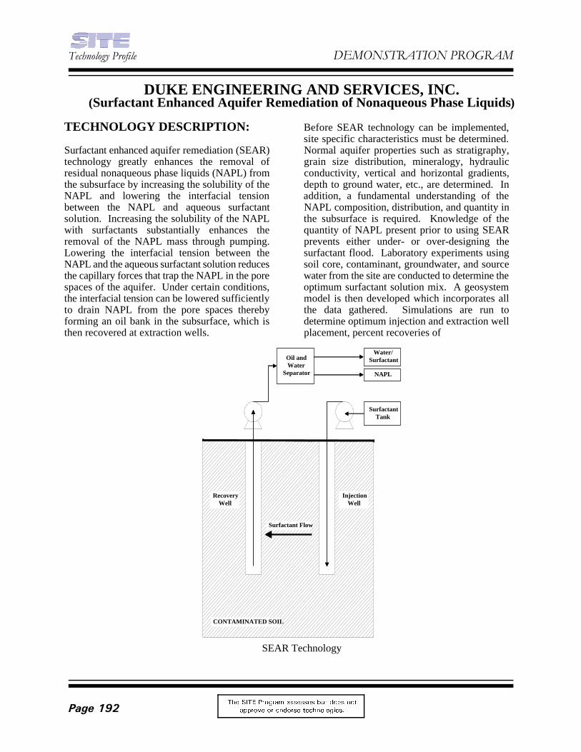
SEAR Technology
DUKE ENGINEERING AND SERVICES, INC.(Surfactant Enhanced Aquifer Remediation of Nonaqueous Phase Liquids)
TECHNOLOGY DESCRIPTION: Before SEAR technology can be implemented,
Surfactant enhanced aquifer remediation (SEAR) Normal aquifer properties such as stratigraphy,technology greatly enhances the removal of grain size distribution, mineralogy, hydraulicresidual nonaqueous phase liquids (NAPL) from conductivity, vertical and horizontal gradients,the subsurface by increasing the solubility of the depth to ground water, etc., are determined. InNAPL and lowering the interfacial tension addition, a fundamental understanding of thebetween the NAPL and aqueous surfactant NAPL composition, distribution, and quantity insolution. Increasing the solubility of the NAPL the subsurface is required. Knowledge of thewith surfactants substantially enhances the quantity of NAPL present prior to using SEARremoval of the NAPL mass through pumping. prevents either under- or over-designing theLowering the interfacial tension between the surfactant flood. Laboratory experiments usingNAPL and the aqueous surfactant solution reduces soil core, contaminant, groundwater, and sourcethe capillary forces that trap the NAPL in the pore water from the site are conducted to determine thespaces of the aquifer. Under certain conditions, optimum surfactant solution mix. A geosystemthe interfacial tension can be lowered sufficiently model is then developed which incorporates allto drain NAPL from the pore spaces thereby the data gathered. Simulations are run toforming an oil bank in the subsurface, which is determine optimum injection and extraction wellthen recovered at extraction wells. placement, percent recoveries of
site specific characteristics must be determined.
)HEUXDU\�����2QJRLQJ�3URMHFW
7KH 6,7( 3URJUDP DVVHVVHV EXW GRHV QRW
DSSURYH RU HQGRUVH WHFKQRORJLHV� 3DJH����
the compounds injected, contaminant concentration STATUS:levels in the effluent, percent removal of thecontaminant mass, and all other pertinent results of SEAR technology was accepted into the Superfundthe surfactant flood. Innovative Technology Evaluation (SITE)
Once the surfactant flood has been fully designed, the scheduled for demonstration at the end of Novembersurfactant solution is injected into the contaminated 1998 at the Pearl Harbor demonstration site in Oahu,zone in the subsurface through one or more wells. Hawaii.The surfactant is drawn through the subsurface bypumping at surrounding extraction wells. As the SEAR technology has been successfully demonstratedsurfactant moves through the subsurface it solubilizes with three separate surfactant floods at a U.S. Airor, if the design calls for it, mobilizes the NAPL for Force base containing chlorinated solventrecovery at the extraction wells. The recovered contamination in an alluvial aquifer.groundwater and NAPL are then typically sent to aphase separator. The recovered NAPL is either FOR FURTHER INFORMATION:disposed of or recycled, and the groundwater andsurfactant is treated. For large scale projects, EPA PROJECT MANAGER:recovery and reuse of the surfactant from the effluent Tom Holdsworthstream is economical. U.S. EPA
WASTE APPLICABILITY: 26 West Martin Luther King Drive
SEAR technology is applicable for the rapid removal 513-569-7675of residual phase NAPL in the subsurface. Although Fax: 513-569-7676it does not directly remediate the dissolved phaseplume, removal of the source zone contamination can TECHNOLOGY DEVELOPER CONTACT:greatly reduce long term liability and risk. SEAR Dick Jackson or John Londergantechnology can be effective for the removal of a Duke Engineering and Services, Inc.broad range of organic contaminants. This 9111 Research Blvd.technology may not be suitable for sites with low Austin, TX 78758hydraulic permeabilities (10 cm/sec or less). 512-425-2000-5
Demonstration program in 1997. The technology is
National Risk Management Research Laboratory
Cincinnati, OH 45268
Fax: 512-425-2199
7HFKQRORJ\�3URILOH '(021675$7,21�352*5$0
7KH 6,7( 3URJUDP DVVHVVHV EXW GRHV QRW
DSSURYH RU HQGRUVH WHFKQRORJLHV�3DJH����
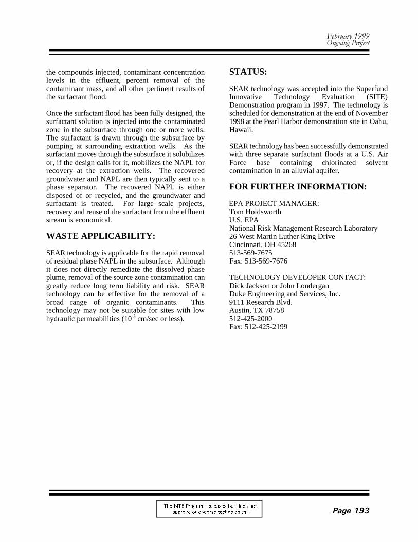
Schematic of the Reactive Barrier Technology
ENVIROMETAL TECHNOLOGIES, INC.(Reactive Barrier)
TECHNOLOGY DESCRIPTION: primarily on the surface area of the iron or its
The Reactive Barrier technology is an innovative dechlorination reaction is typically accompaniedtreatment system that uses the oxidation capacity by an increase in groundwater pH and a decreaseof zero-valent iron to induce reduction of oxidized in oxidation/reduction potential. Inorganicmetals, reductive dechlorination of chlorinated constituents such as calcium, magnesium, andvolatile organic compounds (VOCs), and iron combine with carbonate or hydroxide ions inimmobilization of some metals such as uranium the treated water to form compounds such asby a combination of reduction and sorbtion. metal carbonates and metal hydroxides that precipitate from solution as groundwater movesGranular zero-valent iron oxidizes within the through the iron. Due to the precipitation of thesereactor vessel or reactive wall. As groundwater metallic compounds from solution, the reaction iscontaining VOCs flows through the reactor and also typically accompanied by a decrease in totalaround these granules, electrons released by dissolved solids in the groundwater.oxidation of the iron create a highly reducingenvironment in solution. WASTE APPLICABILITY:
The hydrocarbon-chloride bonds in the The Reactive Barrier technology is applicable tochlorinated contaminants become unstable and subsurface or above-ground treatment of VOCsbreak down sequentially, forming less chlorinated and metals in groundwater or wastewater. Thecompounds and releasing nontoxic chloride ions technology is adaptable to a variety of sites whento the groundwater. The completely hydrolyzed used in combination with funnel and gate systems.hydrocarbon compounds are nontoxic and degrade Depth of the contaminated groundwater is thenaturally. The rate of reaction depends only constraint on the applicability of the
abundance in the permeable reactive media. The
technology.
)HEUXDU\�����2QJRLQJ�3URMHFW
7KH 6,7( 3URJUDP DVVHVVHV EXW GRHV QRW
DSSURYH RU HQGRUVH WHFKQRORJLHV� 3DJH����
STATUS: FOR FURTHER INFORMATION:
The technology was accepted into the SITE EPA PROJECT MANAGER:Demonstration Program in 1996. The Thomas Holdsworthdemonstration of the technology is currently in U.S. EPAprogress at the Rocky Flats Environmental National Risk Management ResearchTechnology Site in Golden, Colorado. The Laboratorytechnology’s effectiveness will be evaluated 26 West Martin Luther King Drivethrough sampling and analysis of untreated and Cincinnati, OH 45268 treated groundwater that is collected by a french 513-569-7675drain system and transferred to two subsurfacereactor tanks through gravity flow. Preliminary TECHNOLOGY CONTACTresults from the evaluation will be available in John Voganmid to late 1999. Envirometal Technologies Incorporated
42 Arrow RoadGuelph, Ontario, CanadaN1K 1S6519-824-0432
7HFKQRORJ\�3URILOH '(021675$7,21�352*5$0
7KH 6,7( 3URJUDP DVVHVVHV EXW GRHV QRW
DSSURYH RU HQGRUVH WHFKQRORJLHV�3DJH����
GEOKINETICS INTERNATIONAL, INC.(Electroheat-Enhanced Nonaqueous-Phase Liquids Removal)
TECHNOLOGY DESCRIPTION: • Nascent biological activity will typically
Geokinetics has developed and fully up rate is managed carefully). Thiscommercialized a novel in-situ process for the greatly increases natural biodegradation.extraction and/or destruction of organic materials When the treatment zone has reached its(nonaqueous phase liquids [NAPL]) from ground operating temperature, a combination ofand groundwater. The process combines a novel established extraction techniques aredirect electrical heating process with established applied as appropriate to remove most orsoil vapor, dual phase and other extraction all of the NAPL. Treatment timesapproaches. Heat is produced directly in the typically include:treatment zone by the passage of an AC currentthrough the soil matrix. In effect, the ground and • 1 month for heat-upgroundwater become the electrical resistor in a • 4 to 8 months for primary extractionconventional resistive heating circuit.
Multi-phase electrical current is supplied to thesoil matrix using proprietary high surface area The technology is broadly applicable forelectrodes inserted directly into the ground. enhancing the removal of NAPLs and DNAPLsElectrical current, heat-up rate, and other from a broad range of ground types. Recoveredoperating parameters are regulated by a and destroyed contaminants include fuel oil,proprietary computer-based (impedance diesel, kerosene, PAHs, coal tar, hydraulic fluid,matching) control system. This system TCE, and other chlorinated solvents. groundincorporates automated data logging, fault types treated include clays, silty clays, shale beds,tolerance, and remote operation to minimize field gravel deposits, etc. The technology has beenlabor requirements. deployed alongside, inside, and underneath
The process works by gradually and uniformlyheating the treatment zone to 60 to 80 (C. This STATUS:produces the following effects:
• NAPL viscosity is significantly reduced the technology in Europe and has more than 40• A density inversion of many dense projects completed or in progress. In the United
nonaqueous-phase liquid (DNAPL) States, Geokinetics’ technology was accepted incomponents will occur causing it to float the Superfund Innovative Technology Evaluationto the top of the saturated zone (SITE) program in 1997. The technology is
• The smear zone will greatly reduce or scheduled for U.S. demonstration under the SITEeven collapse program during September and October 1998 at
increase dramatically (provided the heat-
WASTE APPLICABILITY:
existing buildings and structures.
Geokinetics first developed and commercialized
the Pearl Harbor demonstration site in Oahu,Hawaii.
)HEUXDU\�����2QJRLQJ�3URMHFW
7KH 6,7( 3URJUDP DVVHVVHV EXW GRHV QRW
DSSURYH RU HQGRUVH WHFKQRORJLHV� 3DJH����
FOR FURTHER INFORMATION:
EPA PROJECT MANAGER:Tom HoldsworthU.S. Environmental Protection AgencyOffice of Research and Development26 West Martin Luther King DriveCincinnati, OH 45268513-569-7675 Fax: 513-569-7676
TECHNOLOGY DEVELOPER CONTACT:Dr. Stephen R. ClarkeGeokinetics International, Inc.829 Heinz StreetBerkeley, CA 94563510-704-2941 Fax: 510-848-1581Website: www.geokinetics.com
7HFKQRORJ\�3URILOH '(021675$7,21�352*5$0
7KH 6,7( 3URJUDP DVVHVVHV EXW GRHV QRW
DSSURYH RU HQGRUVH WHFKQRORJLHV�3DJH����
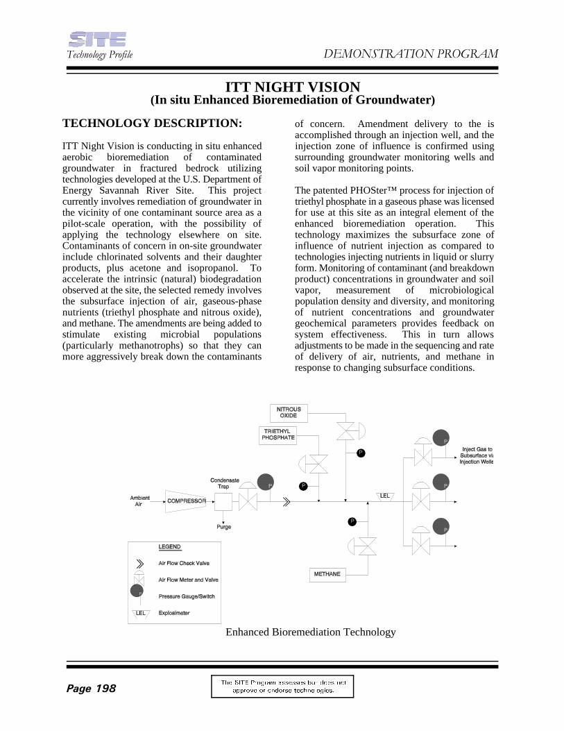
Enhanced Bioremediation Technology
ITT NIGHT VISION(In situ Enhanced Bioremediation of Groundwater)
TECHNOLOGY DESCRIPTION: of concern. Amendment delivery to the is
ITT Night Vision is conducting in situ enhanced injection zone of influence is confirmed usingaerobic bioremediation of contaminated surrounding groundwater monitoring wells andgroundwater in fractured bedrock utilizing soil vapor monitoring points. technologies developed at the U.S. Department ofEnergy Savannah River Site. This project The patented PHOSter™ process for injection ofcurrently involves remediation of groundwater in triethyl phosphate in a gaseous phase was licensedthe vicinity of one contaminant source area as a for use at this site as an integral element of thepilot-scale operation, with the possibility of enhanced bioremediation operation. Thisapplying the technology elsewhere on site. technology maximizes the subsurface zone ofContaminants of concern in on-site groundwater influence of nutrient injection as compared toinclude chlorinated solvents and their daughter technologies injecting nutrients in liquid or slurryproducts, plus acetone and isopropanol. To form. Monitoring of contaminant (and breakdownaccelerate the intrinsic (natural) biodegradation product) concentrations in groundwater and soilobserved at the site, the selected remedy involves vapor, measurement of microbiologicalthe subsurface injection of air, gaseous-phase population density and diversity, and monitoringnutrients (triethyl phosphate and nitrous oxide), of nutrient concentrations and groundwaterand methane. The amendments are being added to geochemical parameters provides feedback onstimulate existing microbial populations system effectiveness. This in turn allows(particularly methanotrophs) so that they can adjustments to be made in the sequencing and ratemore aggressively break down the contaminants of delivery of air, nutrients, and methane in
accomplished through an injection well, and the
response to changing subsurface conditions.
)HEUXDU\�����2QJRLQJ�3URMHFW
7KH 6,7( 3URJUDP DVVHVVHV EXW GRHV QRW
DSSURYH RU HQGRUVH WHFKQRORJLHV� 3DJH����
WASTE APPLICABILITY: successfully stimulated the growth of native
This enhanced bioremediation technology breaks phospholipid fatty acid assays and methanotrophdown volatile organic compounds in groundwater. most probable number plate counts.Compounds which are amenable to intrinsic Corresponding decreases in concentrations of(natural) biodegradation can be degraded more contaminants of concern have also beenrapidly when the subsurface microbial populations discernible. are stimulated through the injection of air,gaseous-phase nutrients, and methane. By FOR FURTHER INFORMATION:providing an aerobic environment for contaminantdegradation, harmless breakdown products are EPA PROJECT MANAGER:produced and toxic daughter products of Vince Gallardoanaerobic degradation of chlorinated solvents US EPA(such as vinyl chloride) can be broken down National Risk Management Researchcompletely. This in-situ technology is especially Laboratoryapplicable in situation where subsurface 26 W. Martin Luther King Driveinfrastructure (for example, networks of utilities) Cincinnati, OH 45268limit or preclude excavation or extraction 513-569-7176technologies.
STATUS: Rosann Kryczkowski
The enhanced bioremediation system, currently ITT Night Visionbeing used in the ongoing RCRA corrective action 7635 Plantation Roadinterim measure at the ITT Night Vision facility, Roanoke, VA 24019-3257was accepted into the SITE program in 1997, with 540-362-7356system start up occurring in March of 1998. The Fax: 540-362-7370technology had previously been approved by EPARegion 3 as an Interim Measure part of the TECHNOLOGY DEVELOPER CONTACT:facility’s ongoing RCRA Corrective Action Brian B. Looney, Ph.D.program. Westinghouse Savannah River Company
SITE program participants collected groundwater Aiken, SC 29808quality and microbiological data prior to system 803-725-3692start up (baseline monitoring) and between the air Fax: 803-725-7673and nutrient injection campaigns (interimmonitoring). Baseline monitoring established astatistical reference point for contaminants ofconcern in groundwater. Interim monitoringsuggests that the initial injection campaigns have
microbial populations based upon the results of
ITT NIGHT VISION PROJECT MANAGER:
Manager, Environmental, Health & Safety
Savannah River Technology Center
7HFKQRORJ\�3URILOH '(021675$7,21�352*5$0
7KH 6,7( 3URJUDP DVVHVVHV EXW GRHV QRW
DSSURYH RU HQGRUVH WHFKQRORJLHV�3DJH����
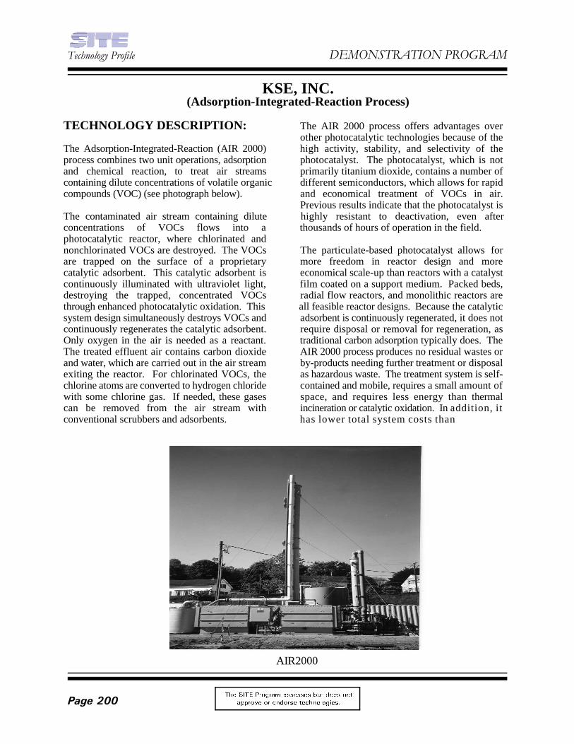
AIR2000
KSE, INC.(Adsorption-Integrated-Reaction Process)
TECHNOLOGY DESCRIPTION: The AIR 2000 process offers advantages over
The Adsorption-Integrated-Reaction (AIR 2000) high activity, stability, and selectivity of theprocess combines two unit operations, adsorption photocatalyst. The photocatalyst, which is notand chemical reaction, to treat air streams primarily titanium dioxide, contains a number ofcontaining dilute concentrations of volatile organic different semiconductors, which allows for rapidcompounds (VOC) (see photograph below). and economical treatment of VOCs in air.
The contaminated air stream containing dilute highly resistant to deactivation, even afterconcentrations of VOCs flows into a thousands of hours of operation in the field.photocatalytic reactor, where chlorinated andnonchlorinated VOCs are destroyed. The VOCs The particulate-based photocatalyst allows forare trapped on the surface of a proprietary more freedom in reactor design and morecatalytic adsorbent. This catalytic adsorbent is economical scale-up than reactors with a catalystcontinuously illuminated with ultraviolet light, film coated on a support medium. Packed beds,destroying the trapped, concentrated VOCs radial flow reactors, and monolithic reactors arethrough enhanced photocatalytic oxidation. This all feasible reactor designs. Because the catalyticsystem design simultaneously destroys VOCs and adsorbent is continuously regenerated, it does notcontinuously regenerates the catalytic adsorbent. require disposal or removal for regeneration, asOnly oxygen in the air is needed as a reactant. traditional carbon adsorption typically does. TheThe treated effluent air contains carbon dioxide AIR 2000 process produces no residual wastes orand water, which are carried out in the air stream by-products needing further treatment or disposalexiting the reactor. For chlorinated VOCs, the as hazardous waste. The treatment system is self-chlorine atoms are converted to hydrogen chloride contained and mobile, requires a small amount ofwith some chlorine gas. If needed, these gases space, and requires less energy than thermalcan be removed from the air stream with incineration or catalytic oxidation. In addition, itconventional scrubbers and adsorbents. has lower total system costs than
other photocatalytic technologies because of the
Previous results indicate that the photocatalyst is
)HEUXDU\�����2QJRLQJ�3URMHFW
7KH 6,7( 3URJUDP DVVHVVHV EXW GRHV QRW
DSSURYH RU HQGRUVH WHFKQRORJLHV� 3DJH����
these traditional technologies, and can be A 700 SCFM commercial unit is now operating atconstructed of fiberglass reinforced plastic (FRP) a Superfund Site in Rhode Island, destroyingdue to the low operating temperatures. TCE, DCE and vinyl chloride in the combined
WASTE APPLICABILITY: stripper. Preliminary results show that the system
The AIR 2000 process is designed to treat a wide AIR 2000 unit is operating unattended, with therange of VOCs in air, ranging in concentration number of UV lamps being illuminated changingfrom less than 1 to as many as thousands of parts automatically in response to changing flowper million. The process can destroy the conditions for maximum performance atfollowing VOCs: chlorinated hydrocarbons, minimum cost.aromatic and aliphatic hydrocarbons, alcohols,ethers, ketones, and aldehydes. The AIR 2000 Process was accepted into the SITE
The AIR 2000 process can be integrated with objective of demonstrating the performance of theexisting technologies, such as thermal desorption, system at the Superfund site in Rhode Island. air stripping, or soil vapor extraction, to treatadditional media, including soils, sludges, and FOR FURTHER INFORMATION:groundwater.
STATUS: Vince Gallardo
The AIR 2000 process was accepted into the SITE National Risk Management ResearchEmerging Technology Program in 1995. Studies Laboratoryunder the Emerging Technology Program are 26 West Martin Luther King Drivefocusing on (1) developing photocatalysts for a Cincinnati, OH 45268broad range of chlorinated and nonchlorinated 513-569-7176VOCs, and (2) designing advanced and cost- Fax: 513-569-7620effective photocatalytic reactors for remediation E-mail: [email protected] industrial service.
The AIR 2000 Process was initially J.R. Kittrellevaluated at full-scale operation for KSE, Inc.treatment of soil vapor extraction off-gas at P.O. Box 368Loring Air Force Base (AFB). Destruction Amherst, MA 01004efficiency of tetrachloroethene exceeded 99.8 413-549-5506 percent. The performance results were presented Fax: 413-549-5788at the 1996 World Environmental Congress. e-mail: [email protected]
The AIR-I process, an earlier version of the TECHNOLOGY LICENSEE CONTACT:technology, was demonstrated as part of a Dr. Bill de Waalgroundwater remediation demonstration project at Trojan Technologies, Inc.Dover AFB in Dover, Delaware, treating effluent 3020 Gore Roadair from a groundwater stripper. Test results London, Ontario N5V-4T7showed more than 99 percent removal of CANADAdichloroethane (DCA) from air initially 519-457-3400containing about 1 ppm DCA and saturated with Fax: 519-457-3030water vapor.
off-gas from a SVE system and a groundwater
is operating at 99.99% destruction efficiency. The
Demonstration program in 1998, with the
EPA PROJECT MANAGER:
U.S. EPA
TECHNOLOGY DEVELOPER CONTACT:
-
+
Electroosmotic
Liquid Flow
Contaminated Soil
Degradation Zone
Ground Surface
APPLIED ELECTRICAL POTENTIAL
Degradation
Zone
Granular Electrode
Granular Electrode
Borehole
7HFKQRORJ\�3URILOH '(021675$7,21�352*5$0
7KH 6,7( 3URJUDP DVVHVVHV EXW GRHV QRW
DSSURYH RU HQGRUVH WHFKQRORJLHV�3DJH����
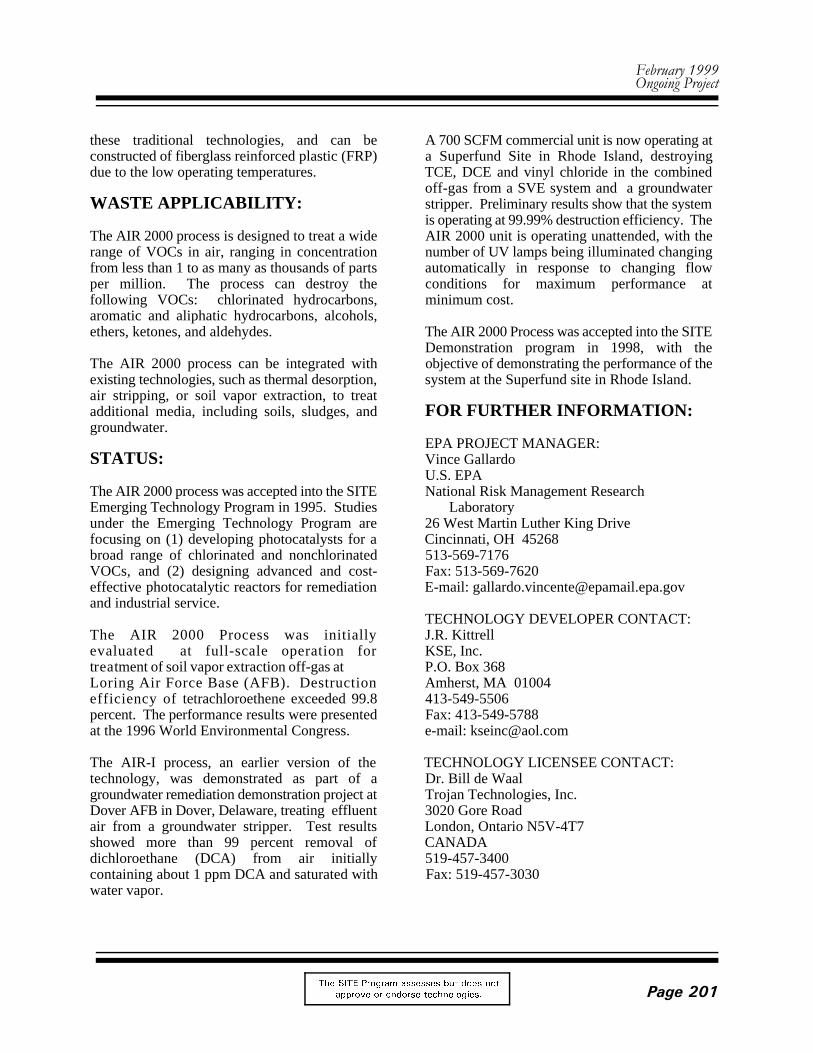
Vertical Configuration of the Lasagna™ Process
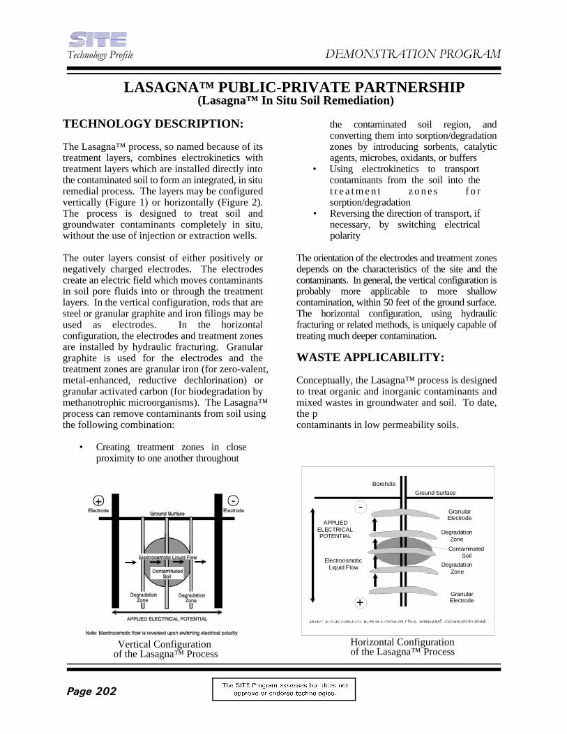
Horizontal Configurationof the Lasagna™ Process
LASAGNA™ PUBLIC-PRIVATE PARTNERSHIP (Lasagna™ In Situ Soil Remediation)
TECHNOLOGY DESCRIPTION: the contaminated soil region, and
The Lasagna™ process, so named because of its zones by introducing sorbents, catalytictreatment layers, combines electrokinetics with agents, microbes, oxidants, or bufferstreatment layers which are installed directly into • Using electrokinetics to transportthe contaminated soil to form an integrated, in situ contaminants from the soil into theremedial process. The layers may be configured t r e a t m e n t z o n e s f o rvertically (Figure 1) or horizontally (Figure 2). sorption/degradationThe process is designed to treat soil and • Reversing the direction of transport, ifgroundwater contaminants completely in situ, necessary, by switching electricalwithout the use of injection or extraction wells. polarity
The outer layers consist of either positively or The orientation of the electrodes and treatment zonesnegatively charged electrodes. The electrodes depends on the characteristics of the site and thecreate an electric field which moves contaminants contaminants. In general, the vertical configuration isin soil pore fluids into or through the treatment probably more applicable to more shallowlayers. In the vertical configuration, rods that are contamination, within 50 feet of the ground surface.steel or granular graphite and iron filings may be The horizontal configuration, using hydraulicused as electrodes. In the horizontal fracturing or related methods, is uniquely capable ofconfiguration, the electrodes and treatment zones treating much deeper contamination.are installed by hydraulic fracturing. Granulargraphite is used for the electrodes and the WASTE APPLICABILITY:treatment zones are granular iron (for zero-valent,metal-enhanced, reductive dechlorination) or Conceptually, the Lasagna™ process is designedgranular activated carbon (for biodegradation by to treat organic and inorganic contaminants andmethanotrophic microorganisms). The Lasagna™ mixed wastes in groundwater and soil. To date,process can remove contaminants from soil using the pthe following combination: contaminants in low permeability soils.
• Creating treatment zones in closeproximity to one another throughout
converting them into sorption/degradation
)HEUXDU\�����2QJRLQJ�3URMHFW
7KH 6,7( 3URJUDP DVVHVVHV EXW GRHV QRW
DSSURYH RU HQGRUVH WHFKQRORJLHV� 3DJH����
STATUS: form. Based on the success of this test, DOE has
The Lasagna™ process (vertical configuration) to clean up the rest of this contaminated locationwas accepted into the SITE Demonstration at PGDP.Program in 1995. Under the SITE Program, withsignificant funding from the U.S. Department of EPA and the University of Cincinnati haveEnergy (DOE), the Lasagna™ process was tested installed horizontal configuration cells atfor 120 days in May 1995 on soil contaminated Rickenbacker Air National Guard Base (ANGB)with trichloroethene (TCE) at DOE’s Paducah near Columbus, Ohio. Support facilities are beingGaseous Diffusion Plant (PGDP) in Kentucky. installed at Offutt Air Force Base (AFB) nearOne of the key objectives of this test was to Omaha, Nebraska. Horizontal configuration cellssuccessfully demonstrate the coupling of will be installed at Offutt AFB in spring 1997electroosmotic flushing of TCE from the clay soil with funding support from the U.S. Air Force.while removing the TCE from the pore water by TCE is the target contaminant at bothin situ adsorption. Steel panels were used as Rickenbacker ANGB and Offutt AFB.electrodes and granular activated carbon (GAC)served as treatment layers in a vertical FOR FURTHER INFORMATION:configuration.
Sampling and analysis of the GAC at the end of Michelle Simon the demonstration revealed a substantial GAC U.S. EPAamount of TCE. Soil samples collected before and National Risk Management Researchafter the demonstration indicated a 98 percent Laboratoryremoval of TCE from tight clay soil, with some 26 West Martin Luther King Drivesamples showing greater than 99 percent removal. Cincinnati, OH 45268TCE soil levels were reduced from the 100 parts 513-569-7775 or 513-569-7469per million (ppm) range to an average Fax: 513-569-7676concentration of 1 ppm.
A second test of the Lasagna™ process in a Michael Rouliervertical configuration was started in August 1996 U.S. EPAat DOE’s PGDP to treat in situ TCE-contaminated National Risk Management Researchsoil to 45 feet below ground surface. A Laboratorysheetpiling method was utilized with hollow 26 West Martin Luther King Drivemandrels for installing electrodes (granular Cincinnati, OH 45268mixture of coke and iron filings) and treatment 513-569-7796zones (iron filings/clay slurry) in thin layers (less Fax: 513-569-7620than 2 inches thick) through stiff clay soil withoutgenerating solid waste. Complications Sa Hoencountered during the operation included Monsanto Companycontamination levels significantly higherthan 800 N. Lindbergh Boulevardanticipated and complex hydrogeology in the St. Louis, MO 63167subsurface. The overall TCE removal efficiency 314-694-5179obtained was in the range of 95 percent for 1 pore Fax: 314-694-1531volume of water flow to over 99 percent for 2.6pore volumes between the treatment zones. Thereare strong indications that some of the TCE wastransported and degraded in the dense non-aqueous phase liquid
recommended that the Lasagna™ process be used
EPA PROJECT MANAGER:
TECHNOLOGY DEVELOPER CONTACT:
7HFKQRORJ\�3URILOH '(021675$7,21�352*5$0
7KH 6,7( 3URJUDP DVVHVVHV EXW GRHV QRW
DSSURYH RU HQGRUVH WHFKQRORJLHV�3DJH����
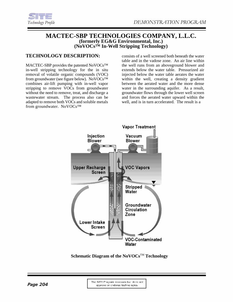
Schematic Diagram of the NoVOCs TechnologyTM
MACTEC-SBP TECHNOLOGIES COMPANY, L.L.C.(formerly EG&G Environmental, Inc.)
(NoVOCs™ In-Well Stripping Technology)
TECHNOLOGY DESCRIPTION: consists of a well screened both beneath the water
MACTEC-SBP provides the patented NoVOCs™ the well runs from an aboveground blower andin-well stripping technology for the in situ extends below the water table. Pressurized airremoval of volatile organic compounds (VOC) injected below the water table aerates the waterfrom groundwater (see figure below). NoVOCs™ within the well, creating a density gradientcombines air-lift pumping with in-well vapor between the aerated water and the more densestripping to remove VOCs from groundwater water in the surrounding aquifer. As a result,without the need to remove, treat, and discharge a groundwater flows through the lower well screenwastewater stream. The process also can be and forces the aerated water upward within theadapted to remove both VOCs and soluble metals well, and is in turn accelerated. The result is afrom groundwater. NoVOCs™
table and in the vadose zone. An air line within
)HEUXDU\�����2QJRLQJ�3URMHFW
7KH 6,7( 3URJUDP DVVHVVHV EXW GRHV QRW
DSSURYH RU HQGRUVH WHFKQRORJLHV� 3DJH����
rising column of aerated water within the well, WASTE APPLICABILITY:essentially acting as an air-lift pump
As the aerated groundwater column rises within volatile petroleum hydrocarbons includingthe well, VOC mass transfer occurs from the benzene, ethylbenzene, and toluene, as well asdissolved phase to the vapor phase. Above the chlorinated solvents such as tetrachloroethene andwater table, a packer is installed at the upper trichloroethene. Highly soluble organics likescreen to prevent the passage of rising water or alcohols and ketones are not easily air-strippedbubbles. The rising water column hits the packer, from water but are readily biodegraded in thethe bubbles burst, and the entrained VOC vapor is oxygen-rich environment produced bystripped off laterally through the screen by an NoVOCs™.upper vacuum casing. The VOC-rich vapor isbrought to the surface for treatment while the STATUS:laterally deflected water circulates back into theaquifer. Reinfiltrating water creates a toroidal The NoVOCs™ technology was accepted into thecirculation pattern around the well, enabling the SITE Demonstration Program in 1995. Thegroundwater to undergo multiple treatment cycles demonstration is underway at Naval Air Stationbefore flowing downgradient. The VOC-rich North Island in San Diego, California. vapor is treated using commercially availabletechniques chosen according to the vapor stream FOR FURTHER INFORMATION:characteristics.
NoVOCs™ also can be used to remove readily Michelle Simonreduced metals from groundwater and stabilize U.S. EPAthem in the vadose zone. Solubilized metals in National Risk Management Researchtheir oxidized states enter the lower screen by the Laboratorysame route as dissolved VOCs in the groundwater. 26 West Martin Luther King DriveThe nonvolatile metals remain in solution as the Cincinnati, OH 45268VOCs are stripped at the upper screen and the 513-569-7469water circulates out of the well. The groundwater Fax: 513-569-7676and soluble metals then pass through aninfiltration and treatment gallery surrounding the TECHNOLOGY DEVELOPER CONTACT:upper well screen. This treatment gallery is Mark McGlatheryimpregnated with a reducing agent that reduces MACTEC-SBP Technologies Company, L.L.C.the soluble metals to an insoluble valence state. 1819 Denver West Drive, Suite 400The insoluble metals accumulate in the infiltration Golden, CO 80401gallery high above the water table and can be 303-278-3100either capped or excavated at the conclusion of Fax: 303-273-5000remedial action.
The process treats groundwater contaminated with
EPA PROJECT MANAGER:
7HFKQRORJ\�3URILOH '(021675$7,21�352*5$0
7KH 6,7( 3URJUDP DVVHVVHV EXW GRHV QRW
DSSURYH RU HQGRUVH WHFKQRORJLHV�3DJH����
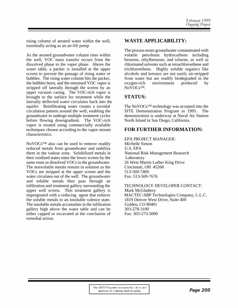
Full-Scale Photocatalytic Air Treatment System
MATRIX PHOTOCATALYTIC INC.(Photocatalytic Air Treatment)
TECHNOLOGY DESCRIPTION:
Matrix Photocatalytic Inc. is developing a titanium toluene, ethylbenzene, and xylene;dioxide (TiO ) photocatalytic air treatment trichloroethene; tetrachloroethane; isopropyl2
technology that destroys volatile organic alcohol; acetone; chloroform; methanol; andcompounds (VOC) and semivolatile organic methyl ethyl ketone. A field-scale system iscompounds in air streams. During treatment, shown in the photograph on the next page.contaminated air at ambient temperatures flowsthrough a fixed TiO catalyst bed activated by WASTE APPLICABILITY:2
ultraviolet (UV) light. Typically, organiccontaminants are destroyed in fractions of a The TiO photocatalytic air treatment technologysecond. can effectively treat dry or moist air. The
Technology advantages include the following: contaminant steam directly, thus eliminating the
• Robust equipment minute have been successfully tested on vapor• No residual toxins extraction operations, air stripper emissions,• No ignition source steam from desorption processes, and VOC• Unattended operation emissions from manufacturing facilities. Other• Low direct treatment cost potential applications include odor removal, stack
The technology has been tested on benzene,
2
technology has been demonstrated to purify
need to condense. Systems of 100 cubic feet per
)HEUXDU\�����2QJRLQJ�3URMHFW
7KH 6,7( 3URJUDP DVVHVVHV EXW GRHV QRW
DSSURYH RU HQGRUVH WHFKQRORJLHV� 3DJH����
gas treatment, soil venting, and manufacturing FOR FURTHER INFORMATION:ultra-pure air for residential, automotive,instrument, and medical needs. Systems of up to EPA PROJECT MANAGER:about 1,000 cubic feet per minute can be cost- Richard Eilerscompetitive with thermal destruction systems. U.S. EPA
STATUS: Laboratory
The TiO photocatalytic air treatment technology Cincinnati, OH 452682
was accepted into SITE Emerging Technology 513-569-7809Program (ETP) in October 1992; the evaluation Fax: 513-569-7111was completed in 1993. Based on results from theETP, this technology was invited to participate in TECHNOLOGY DEVELOPER CONTACT:the SITE Demonstration Program. For further Bob Hendersoninformation about the evaluation under the ETP, Matrix Photocatalytic Inc.refer to the journal article (EPA/600/A-93/282), 22 Pegler Streetwhich is available from EPA. A suitable London, Ontario, Canada N5Z 2B5demonstration site is being sought. 519-660-8669
National Risk Management Research
26 West Martin Luther King Drive
Fax: 519-660-8525
Air Pump
Pressure Gauge
FlowControlRotameter Pressure Gauge
Ground Surface
GasSamplingPort
3-Way BallValve
Bentonite Seal
Stainless Steel Air Injection Probe1 cm ID2 cm OD
ScreenedSection
7HFKQRORJ\�3URILOH '(021675$7,21�352*5$0
7KH 6,7( 3URJUDP DVVHVVHV EXW GRHV QRW
DSSURYH RU HQGRUVH WHFKQRORJLHV�3DJH����
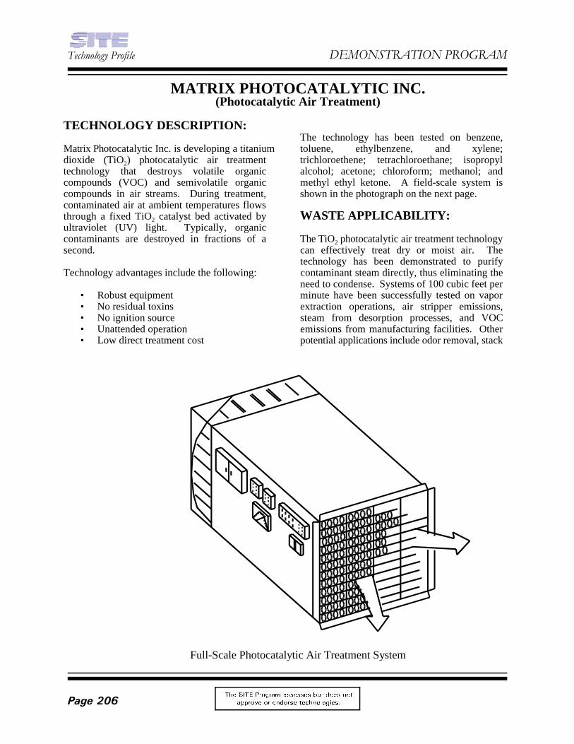
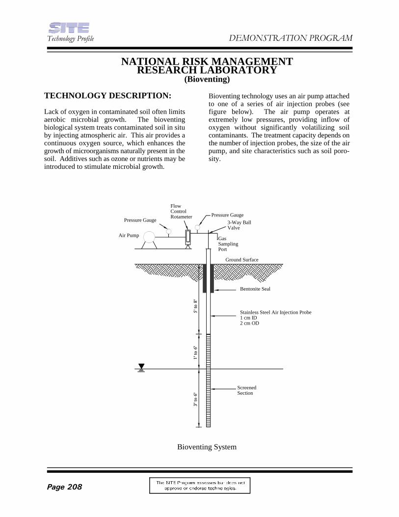
Bioventing System
NATIONAL RISK MANAGEMENTRESEARCH LABORATORY
(Bioventing)
TECHNOLOGY DESCRIPTION: Bioventing technology uses an air pump attached
Lack of oxygen in contaminated soil often limits figure below). The air pump operates ataerobic microbial growth. The bioventing extremely low pressures, providing inflow ofbiological system treats contaminated soil in situ oxygen without significantly volatilizing soilby injecting atmospheric air. This air provides a contaminants. The treatment capacity depends oncontinuous oxygen source, which enhances the the number of injection probes, the size of the airgrowth of microorganisms naturally present in the pump, and site characteristics such as soil poro-soil. Additives such as ozone or nutrients may be sity.introduced to stimulate microbial growth.
to one of a series of air injection probes (see
)HEUXDU\�����2QJRLQJ�3URMHFW
7KH 6,7( 3URJUDP DVVHVVHV EXW GRHV QRW
DSSURYH RU HQGRUVH WHFKQRORJLHV� 3DJH����
WASTE APPLICABILITY: FOR FURTHER INFORMATION:
Bioventing is typically used to treat soil EPA PROJECT MANAGER:contaminated by industrial processes and can treat Jack Hubbardany contamination subject to aerobic microbial U.S. EPAdegradation. Bioventing treats contaminants and National Risk Management Researchcombinations of contaminants with varying Laboratorydegrees of success. 26 West Martin Luther King Drive
STATUS: 513-569-7507
This technology was accepted into the SITEDemonstration Program in July 1991. The TECHNOLOGY DEVELOPER CONTACT:demonstration began in November 1992 at the Paul McCauleyReilly Tar site in St. Louis Park, Minnesota. Soil U.S. EPAat this site is contaminated with polynuclear National Risk Management Researcharomatic hydrocarbons. The project will be Laboratorycompleted in early 1999. 26 West Martin Luther King Drive
Cincinnati, OH 45268
Fax: 513-569-7620
Cincinnati, OH 45268513-569-7444Fax: 513-569-7105
7HFKQRORJ\�3URILOH '(021675$7,21�352*5$0
7KH 6,7( 3URJUDP DVVHVVHV EXW GRHV QRW
DSSURYH RU HQGRUVH WHFKQRORJLHV�3DJH����
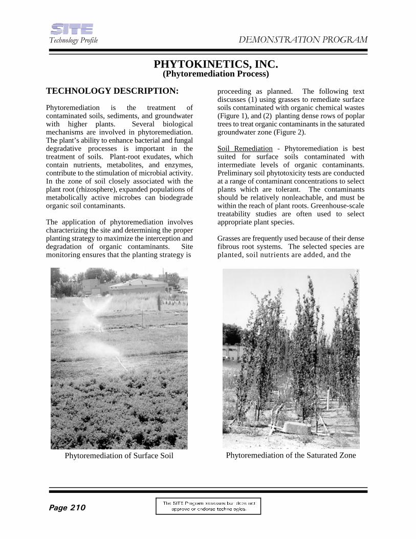
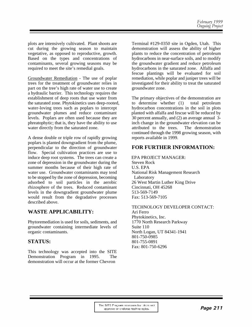
Phytoremediation of Surface Soil Phytoremediation of the Saturated Zone
PHYTOKINETICS, INC.(Phytoremediation Process)
TECHNOLOGY DESCRIPTION: proceeding as planned. The following text
Phytoremediation is the treatment of soils contaminated with organic chemical wastescontaminated soils, sediments, and groundwater (Figure 1), and (2) planting dense rows of poplarwith higher plants. Several biological trees to treat organic contaminants in the saturatedmechanisms are involved in phytoremediation. groundwater zone (Figure 2).The plant’s ability to enhance bacterial and fungaldegradative processes is important in the Soil Remediation - Phytoremediation is besttreatment of soils. Plant-root exudates, which suited for surface soils contaminated withcontain nutrients, metabolites, and enzymes, intermediate levels of organic contaminants.contribute to the stimulation of microbial activity. Preliminary soil phytotoxicity tests are conductedIn the zone of soil closely associated with the at a range of contaminant concentrations to selectplant root (rhizosphere), expanded populations of plants which are tolerant. The contaminantsmetabolically active microbes can biodegrade should be relatively nonleachable, and must beorganic soil contaminants. within the reach of plant roots. Greenhouse-scale
The application of phytoremediation involves appropriate plant species.characterizing the site and determining the properplanting strategy to maximize the interception and Grasses are frequently used because of their densedegradation of organic contaminants. Site fibrous root systems. The selected species aremonitoring ensures that the planting strategy is planted, soil nutrients are added, and the
discusses (1) using grasses to remediate surface
treatability studies are often used to select
)HEUXDU\�����2QJRLQJ�3URMHFW
7KH 6,7( 3URJUDP DVVHVVHV EXW GRHV QRW
DSSURYH RU HQGRUVH WHFKQRORJLHV� 3DJH����
plots are intensively cultivated. Plant shoots are Terminal #129-0350 site in Ogden, Utah. Thiscut during the growing season to maintain demonstration will assess the ability of highervegetative, as opposed to reproductive, growth. plants to reduce the concentration of petroleumBased on the types and concentrations of hydrocarbons in near-surface soils, and to modifycontaminants, several growing seasons may be the groundwater gradient and reduce petroleumrequired to meet the site’s remedial goals. hydrocarbons in the saturated zone. Alfalfa and
Groundwater Remediation - The use of poplar remediation, while poplar and juniper trees will betrees for the treatment of groundwater relies in investigated for their ability to treat the saturatedpart on the tree’s high rate of water use to create groundwater zone. a hydraulic barrier. This technology requires theestablishment of deep roots that use water from The primary objectives of the demonstration arethe saturated zone. Phytokinetics uses deep-rooted, to determine whether (1) total petroleumwater-loving trees such as poplars to intercept hydrocarbon concentrations in the soil in plotsgroundwater plumes and reduce contaminant planted with alfalfa and fescue will be reduced bylevels. Poplars are often used because they are 30 percent annually, and (2) an average annual 3-phreatophytic; that is, they have the ability to use inch change in the groundwater elevation can bewater directly from the saturated zone. attributed to the trees. The demonstration
A dense double or triple row of rapidly growing reports available in 1999.poplars is planted downgradient from the plume,perpendicular to the direction of groundwater FOR FURTHER INFORMATION:flow. Special cultivation practices are use toinduce deep root systems. The trees can create a EPA PROJECT MANAGER:zone of depression in the groundwater during the Steven Rocksummer months because of their high rate of U.S. EPAwater use. Groundwater contaminants may tend National Risk Management Researchto be stopped by the zone of depression, becoming Laboratoryadsorbed to soil particles in the aerobic 26 West Martin Luther King Driverhizosphere of the trees. Reduced contaminant Cincinnati, OH 45268levels in the downgradient groundwater plume 513-569-7149would result from the degradative processes Fax: 513-569-7105described above.
WASTE APPLICABILITY: Ari Ferro
Phytoremediation is used for soils, sediments, and 1770 North Research Parkwaygroundwater containing intermediate levels of Suite 110organic contaminants. North Logan, UT 84341-1941
STATUS: 801-755-0891
This technology was accepted into the SITEDemonstration Program in 1995. Thedemonstration will occur at the former Chevron
fescue plantings will be evaluated for soil
continued through the 1998 growing season, with
TECHNOLOGY DEVELOPER CONTACT:
Phytokinetics, Inc.
801-750-0985
Fax: 801-750-6296
7HFKQRORJ\�3URILOH '(021675$7,21�352*5$0
7KH 6,7( 3URJUDP DVVHVVHV EXW GRHV QRW
DSSURYH RU HQGRUVH WHFKQRORJLHV�3DJH����
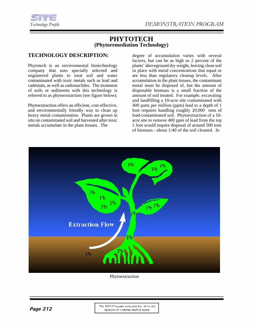
Phytoextraction
PHYTOTECH(Phytoremediation Technology)
TECHNOLOGY DESCRIPTION: degree of accumulation varies with several
Phytotech is an environmental biotechnology plants’ aboveground dry weight, leaving clean soilcompany that uses specially selected and in place with metal concentrations that equal orengineered plants to treat soil and water are less than regulatory cleanup levels. Aftercontaminated with toxic metals such as lead and accumulation in the plant tissues, the contaminantcadmium, as well as radionuclides. The treatment metal must be disposed of, but the amount ofof soils or sediments with this technology is disposable biomass is a small fraction of thereferred to as phytoextraction (see figure below). amount of soil treated. For example, excavating
Phytoextraction offers an efficient, cost-effective, 400 parts per million (ppm) lead to a depth of 1and environmentally friendly way to clean up foot requires handling roughly 20,000 tons ofheavy metal contamination. Plants are grown in lead-contaminated soil. Phytoextraction of a 10-situ on contaminated soil and harvested after toxic acre site to remove 400 ppm of lead from the topmetals accumulate in the plant tissues. The 1 foot would require disposal of around 500 tons
factors, but can be as high as 2 percent of the
and landfilling a 10-acre site contaminated with
of biomass - about 1/40 of the soil cleaned. In
)HEUXDU\�����2QJRLQJ�3URMHFW
7KH 6,7( 3URJUDP DVVHVVHV EXW GRHV QRW
DSSURYH RU HQGRUVH WHFKQRORJLHV� 3DJH����
the example cited, six to eight crops would Phytotech has conducted several fieldtypically be needed, with three or four crops per demonstrations of its rhizofiltration technologygrowing season. for the removal of (1) cesium/strontium at
Compared to traditional remedial technologies, groundwater at a DOE site in Ashtabula, Ohio. Atphytoextraction offers the following benefits: Chernobyl, sunflowers were shown to extract 95
• Lower cost within 10 days. At the Ashtabula site, Phytotech• Applicability to a broad range of ran a 9-month pilot demonstration during which
metals incoming water containing as much as 450 parts• Potential for recycling the per billion (ppb) uranium was treated to 5 ppb or
metal-rich biomass less of uranium.• Minimal environmental
disturbance FOR FURTHER INFORMATION:• Minimization of secondary air-
and water-borne wastes EPA PROJECT MANAGER:
WASTE APPLICABILITY: U.S. EPA
Phytotech's phytoextraction technology can be Laboratoryused to clean soil or sediments contaminated with 26 West Martin Luther King Drivelead, cadmium, chromium, cesium/strontium and Cincinnati, OH 45268uranium. Phytoremediation of other metals such 513-569-7149as arsenic, zinc, copper, and thorium is in the Fax: 513-569-7105research stage.
STATUS: Michael Blaylock (ext. 13) or
Phytotech was accepted into the SITE PhytotechDemonstration Program in 1997. Under the SITE One Deer Park Drive, Suite IProgram, Phytotech is demonstrating its Monmouth Junction, NJ 08852phytoremediation technology at a former battery 732-438-0900manufacturing facility in Trenton, New Jersey. Fax: 732-438-1209where soil is contaminated with lead. The site has E-Mail: [email protected] orbeen prepared and characterized, and two crops [email protected] planted and harvested in late summer 1998.Phytotech has also conducted several successfulfield trials of its phytoextraction technology atother contaminated sites in the U.S. and abroad.
Chernobyl, and (2) uranium from contaminated
percent of the radionuclides from a small pond
Steven Rock
National Risk Management Research
TECHNOLOGY DEVELOPER CONTACT:
Eric Muhr (ext. 32)
7HFKQRORJ\�3URILOH '(021675$7,21�352*5$0
7KH 6,7( 3URJUDP DVVHVVHV EXW GRHV QRW
DSSURYH RU HQGRUVH WHFKQRORJLHV�3DJH����
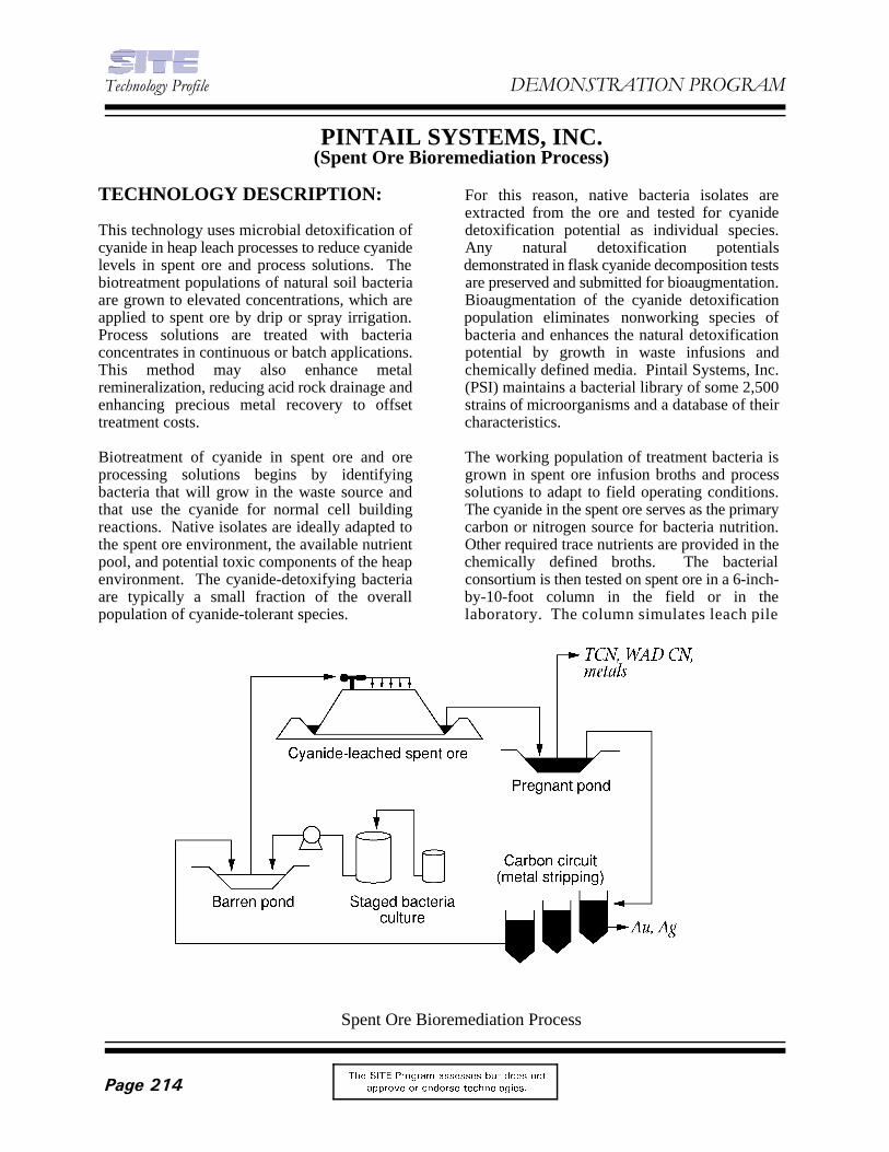
Spent Ore Bioremediation Process
PINTAIL SYSTEMS, INC.(Spent Ore Bioremediation Process)
TECHNOLOGY DESCRIPTION: For this reason, native bacteria isolates are
This technology uses microbial detoxification of detoxification potential as individual species.cyanide in heap leach processes to reduce cyanide Any natural detoxification potentialslevels in spent ore and process solutions. The demonstrated in flask cyanide decomposition testsbiotreatment populations of natural soil bacteria are preserved and submitted for bioaugmentation.are grown to elevated concentrations, which are Bioaugmentation of the cyanide detoxificationapplied to spent ore by drip or spray irrigation. population eliminates nonworking species ofProcess solutions are treated with bacteria bacteria and enhances the natural detoxificationconcentrates in continuous or batch applications. potential by growth in waste infusions andThis method may also enhance metal chemically defined media. Pintail Systems, Inc.remineralization, reducing acid rock drainage and (PSI) maintains a bacterial library of some 2,500enhancing precious metal recovery to offset strains of microorganisms and a database of theirtreatment costs. characteristics.
Biotreatment of cyanide in spent ore and ore The working population of treatment bacteria isprocessing solutions begins by identifying grown in spent ore infusion broths and processbacteria that will grow in the waste source and solutions to adapt to field operating conditions.that use the cyanide for normal cell building The cyanide in the spent ore serves as the primaryreactions. Native isolates are ideally adapted to carbon or nitrogen source for bacteria nutrition.the spent ore environment, the available nutrient Other required trace nutrients are provided in thepool, and potential toxic components of the heap chemically defined broths. The bacterialenvironment. The cyanide-detoxifying bacteria consortium is then tested on spent ore in a 6-inch-are typically a small fraction of the overall by-10-foot column in the field or in thepopulation of cyanide-tolerant species. laboratory. The column simulates leach pile
extracted from the ore and tested for cyanide
)HEUXDU\�����2QJRLQJ�3URMHFW
7KH 6,7( 3URJUDP DVVHVVHV EXW GRHV QRW
DSSURYH RU HQGRUVH WHFKQRORJLHV� 3DJH����
conditions, so that detoxification rates, process STATUS:completion, and effluent quality can be verified.Following column tests, a field test may be This technology was accepted into the SITEconducted to verify column results. Demonstration Program in May 1994. A site
The spent ore is remediated by first setting up a selected for the demonstration. Preliminarystage culturing system to establish working treatability tests have been completed. Inpopulations of cyanide-degrading bacteria at the addition, PSI has completed two full-scalemine site. Bacterial solutions are then applied cyanide detoxification projects.directly to the heap using the same systemoriginally designed to deliver cyanide solutions to FOR FURTHER INFORMATION:the heap leach pads (see figure on previous page).Cyanide concentrations and leachable metals are EPA PROJECT MANAGER:then measured in heap leach solutions. This Jack Hubbardmethod of cyanide degradation in spent ore leach U.S. EPApads degrades cyanide more quickly than methods National Risk Management Researchwhich treat only rinse solutions from the pad. In Laboratoryaddition to cyanide degradation, biological 26 West Martin Luther King Drivetreatment of heap leach pads has also shown Cincinnati, OH 45268significant biomineralization and reduction of 513-569-7507leachable metals in heap leachate solutions. Fax: 513-569-7620
WASTE APPLICABILITY: TECHNOLOGY DEVELOPER CONTACT:
The spent ore bioremediation process can be Pintail Systems, Inc.applied to treat cyanide contamination, spent ore 11801 East 33rd Avenue, Suite Cheaps, waste rock dumps, mine tailings, and Aurora, CO 80010process water from gold and silver mining 303-367-8443operations. Fax: 303-364-2120
located in Battle Mountain, Nevada has been
Leslie Thompson
7HFKQRORJ\�3URILOH '(021675$7,21�352*5$0
7KH 6,7( 3URJUDP DVVHVVHV EXW GRHV QRW
DSSURYH RU HQGRUVH WHFKQRORJLHV�3DJH����
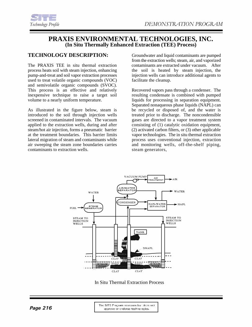
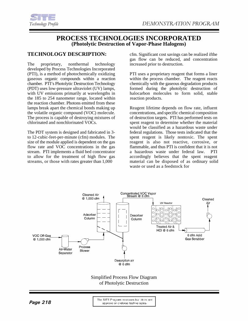
In Situ Thermal Extraction Process
PRAXIS ENVIRONMENTAL TECHNOLOGIES, INC.(In Situ Thermally Enhanced Extraction (TEE) Process)
TECHNOLOGY DESCRIPTION: Groundwater and liquid contaminants are pumped
The PRAXIS TEE in situ thermal extraction contaminants are extracted under vacuum. Afterprocess heats soil with steam injection, enhancing the soil is heated by steam injection, thepump-and-treat and soil vapor extraction processes injection wells can introduce additional agents toused to treat volatile organic compounds (VOC) facilitate the cleanup.and semivolatile organic compounds (SVOC).This process is an effective and relatively Recovered vapors pass through a condenser. Theinexpensive technique to raise a target soil resulting condensate is combined with pumpedvolume to a nearly uniform temperature. liquids for processing in separation equipment.
As illustrated in the figure below, steam is be recycled or disposed of, and the water isintroduced to the soil through injection wells treated prior to discharge. The noncondensiblescreened in contaminated intervals. The vacuum gases are directed to a vapor treatment systemapplied to the extraction wells, during and after consisting of (1) catalytic oxidation equipment,steam/hot air injection, forms a pneumatic barrier (2) activated carbon filters, or (3) other applicableat the treatment boundaries. This barrier limits vapor technologies. The in situ thermal extractionlateral migration of steam and contaminants while process uses conventional injection, extractionair sweeping the steam zone boundaries carries and monitoring wells, off-the-shelf piping,contaminants to extraction wells. steam generators,
from the extraction wells; steam, air, and vaporized
Separated nonaqueous phase liquids (NAPL) can
)HEUXDU\�����2QJRLQJ�3URMHFW
7KH 6,7( 3URJUDP DVVHVVHV EXW GRHV QRW
DSSURYH RU HQGRUVH WHFKQRORJLHV� 3DJH����
condensers, heat exchangers, separation Soil PRGs for TCE and PCE were 58 milligramsequipment, vacuum pumps, and vapor emission per kilogram (mg/Kg) and 12 mg/Kg respectively.control equipment. A total of 41 post-characterization soil samples
WASTE APPLICABILITY: met by the technology. Thirty-five of the 41
The in situ thermal extraction process removes Thirty-five of the 41 samples also had TCEVOCs and SVOCs from contaminated soils and concentrations below the PRG. There were 33groundwater. The process primarily treats samples that had both TCE and PCEchlorinated solvents such as trichloroethene concentrations below the specified PRGs.(TCE), tetrachloroethene (PCE), and dichloro- Detailed reports on the demonstration are inbenzene; hydrocarbons such as gasoline, diesel, preparation and will be available from EPA inand jet fuel; and mixtures of these compounds. 1999. The developer is presently seeking patents
The process can be applied to rapid cleanup of to seek opportunities at other U.S. Department ofsource areas such as dense NAPL pools below the Defense facilities.water table surface, light NAPL pools floating onthe water table surface, and NAPL contamination FOR FURTHER INFORMATION:remaining after using conventional pumpingtechniques. Subsurface conditions are amenable EPA PROJECT MANAGER:to biodegradation of residual contaminants, if Paul dePercinnecessary, after application of the thermal U.S. EPAprocess. A cap is required for implementation of National Risk Management Researchthe process near the soil surface. For dense NAPL Laboratorycompounds in high concentrations, a barrier must 26 West Martin Luther King Drivebe present or created to prevent downward Cincinnati, OH 45268percolation of the NAPLs. The process is 513-569-7797applicable in less permeable soils with the use of Fax: 513-569-7105novel delivery systems such as horizontal wells or E-Mail: [email protected].
STATUS: Lloyd Stewart
This technology was accepted into the SITE 1440 Rollins RoadDemonstration Program in August 1993. The Burlingame, CA 94010demonstration occurred at a former waste 650-548-9288management area located at Operable Unit 2 at Fax: 650-548-9287Hill Air Force Base in Ogden, Utah, during June E-mail: [email protected] July 1997. The demonstration site was thelocation of two former unlined trenches that Major Paul B. Devanereceived unknown quantities of various U.S. Air Force Research Laboratory, Environicschlorinated solvent wastes from 1967 to 1975. Directorate
The demonstration focused primarily on assessing Tyndall AFB, FL 32403-5319and recovering dense NAPL from the trough area 850-283-6288and reducing TCE and PCE levels in the lowersaturated zone so as to meet or exceed the Recordof Decision (ROD) cleanup goals and thePreliminary Remedial Goals (PRG) establishedfor the site’s soils.
were collected to determine if these goals were
samples had PCE concentrations below the PRG.
on various aspects of the system, while continuing
TECHNOLOGY DEVELOPER CONTACTS:
Praxis Environmental Technologies, Inc.
139 Barnes Drive, Suite 2
7HFKQRORJ\�3URILOH '(021675$7,21�352*5$0
7KH 6,7( 3URJUDP DVVHVVHV EXW GRHV QRW
DSSURYH RU HQGRUVH WHFKQRORJLHV�3DJH����
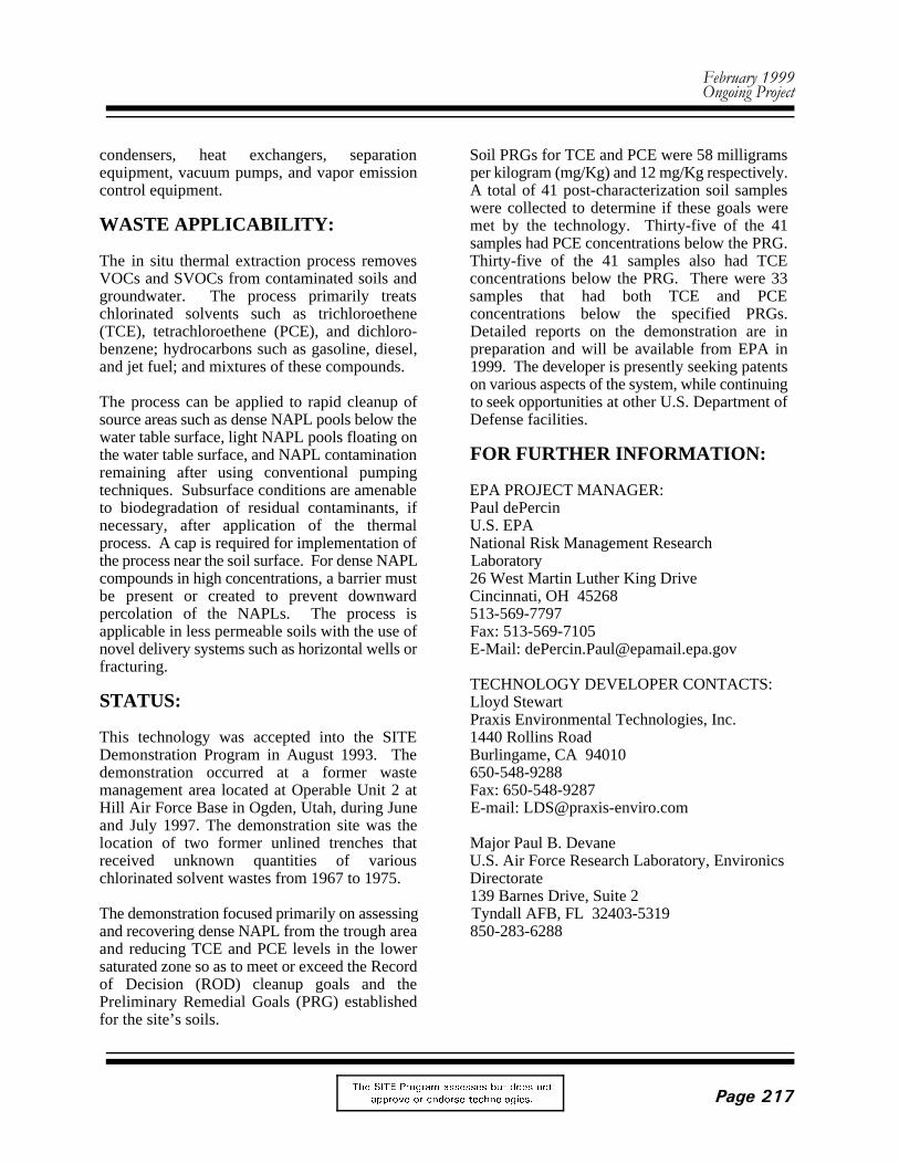
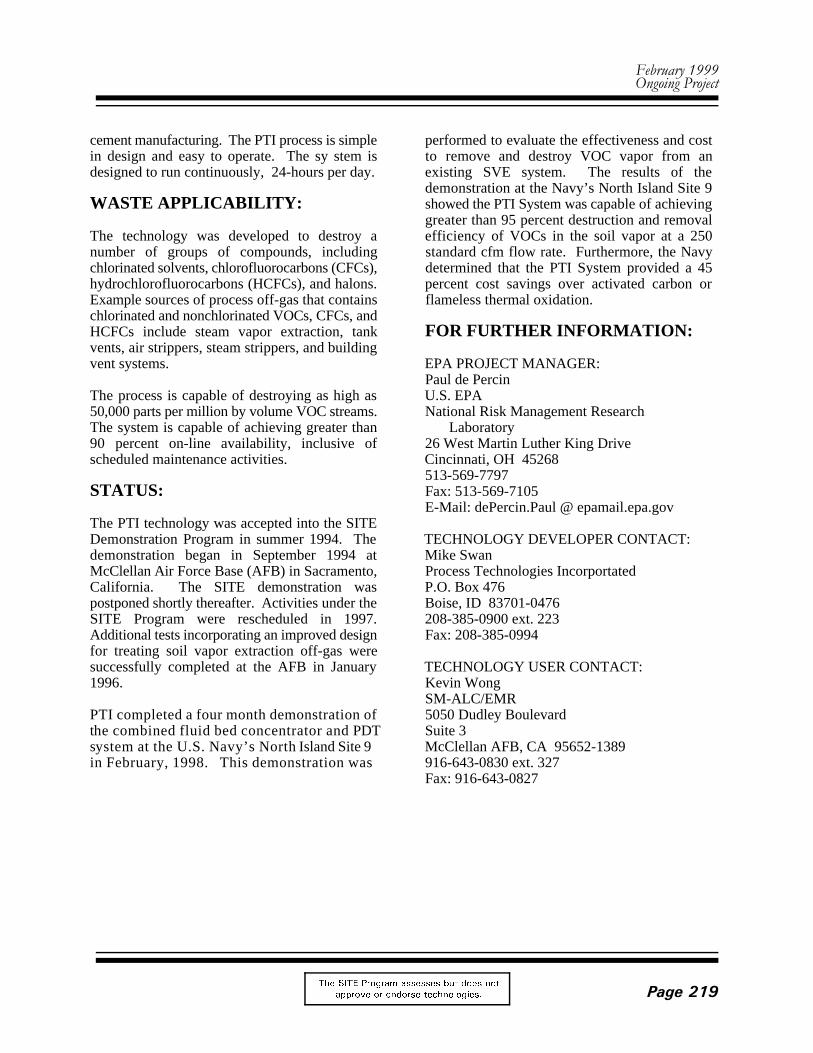
Simplified Process Flow Diagramof Photolytic Destruction
PROCESS TECHNOLOGIES INCORPORATED(Photolytic Destruction of Vapor-Phase Halogens)
TECHNOLOGY DESCRIPTION: cfm. Significant cost savings can be realized ifthe
The proprietary, nonthermal technology increased prior to destruction. developed by Process Technologies Incorporated(PTI), is a method of photochemically oxidizing PTI uses a proprietary reagent that forms a linergaseous organic compounds within a reaction within the process chamber. The reagent reactschamber. PTI’s Photolytic Destruction Technology chemically with the gaseous degradation products(PDT) uses low-pressure ultraviolet (UV) lamps, formed during the photolytic destruction ofwith UV emissions primarily at wavelengths in halocarbon molecules to form solid, stablethe 185 to 254 nanometer range, located within reaction products.the reaction chamber. Photons emitted from theselamps break apart the chemical bonds making up Reagent lifetime depends on flow rate, influentthe volatile organic compound (VOC) molecule. concentrations, and specific chemical compositionThe process is capable of destroying mixtures of of destruction targets. PTI has performed tests onchlorinated and nonchlorinated VOCs. spent reagent to determine whether the material
The PDT system is designed and fabricated in 3- federal regulations. Those tests indicated that theto 12-cubic-feet-per-minute (cfm) modules. The spent reagent is likely nontoxic. The spentsize of the module applied is dependent on the gas reagent is also not reactive, corrosive, orflow rate and VOC concentrations in the gas flammable, and thus PTI is confident that it is notstream. PTI implements a fluid bed concentrator a hazardous waste under federal law. PTIto allow for the treatment of high flow gas accordingly believes that the spent reagentstreams, or those with rates greater than 1,000 material can be disposed of as ordinary solid
gas flow can be reduced, and concentration
would be classified as a hazardous waste under
waste or used as a feedstock for
)HEUXDU\�����2QJRLQJ�3URMHFW
7KH 6,7( 3URJUDP DVVHVVHV EXW GRHV QRW
DSSURYH RU HQGRUVH WHFKQRORJLHV� 3DJH����
cement manufacturing. The PTI process is simple performed to evaluate the effectiveness and costin design and easy to operate. The sy stem is to remove and destroy VOC vapor from andesigned to run continuously, 24-hours per day. existing SVE system. The results of the
WASTE APPLICABILITY: showed the PTI System was capable of achieving
The technology was developed to destroy a efficiency of VOCs in the soil vapor at a 250number of groups of compounds, including standard cfm flow rate. Furthermore, the Navychlorinated solvents, chlorofluorocarbons (CFCs), determined that the PTI System provided a 45hydrochlorofluorocarbons (HCFCs), and halons. percent cost savings over activated carbon orExample sources of process off-gas that contains flameless thermal oxidation.chlorinated and nonchlorinated VOCs, CFCs, andHCFCs include steam vapor extraction, tank FOR FURTHER INFORMATION:vents, air strippers, steam strippers, and buildingvent systems. EPA PROJECT MANAGER:
The process is capable of destroying as high as U.S. EPA50,000 parts per million by volume VOC streams. National Risk Management ResearchThe system is capable of achieving greater than Laboratory90 percent on-line availability, inclusive of 26 West Martin Luther King Drivescheduled maintenance activities. Cincinnati, OH 45268
STATUS: Fax: 513-569-7105
The PTI technology was accepted into the SITEDemonstration Program in summer 1994. The TECHNOLOGY DEVELOPER CONTACT:demonstration began in September 1994 at Mike SwanMcClellan Air Force Base (AFB) in Sacramento, Process Technologies IncorportatedCalifornia. The SITE demonstration was P.O. Box 476postponed shortly thereafter. Activities under the Boise, ID 83701-0476SITE Program were rescheduled in 1997. 208-385-0900 ext. 223Additional tests incorporating an improved design Fax: 208-385-0994for treating soil vapor extraction off-gas weresuccessfully completed at the AFB in January TECHNOLOGY USER CONTACT:1996. Kevin Wong SM-ALC/EMRPTI completed a four month demonstration of 5050 Dudley Boulevardthe combined fluid bed concentrator and PDT Suite 3system at the U.S. Navy’s North Island Site 9 McClellan AFB, CA 95652-1389in February, 1998. This demonstration was 916-643-0830 ext. 327
demonstration at the Navy’s North Island Site 9
greater than 95 percent destruction and removal
Paul de Percin
513-569-7797
E-Mail: dePercin.Paul @ epamail.epa.gov
Fax: 916-643-0827
7HFKQRORJ\�3URILOH '(021675$7,21�352*5$0
7KH 6,7( 3URJUDP DVVHVVHV EXW GRHV QRW
DSSURYH RU HQGRUVH WHFKQRORJLHV�3DJH����
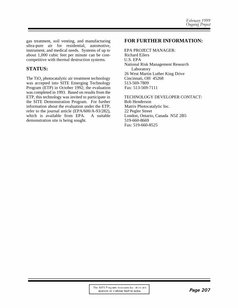
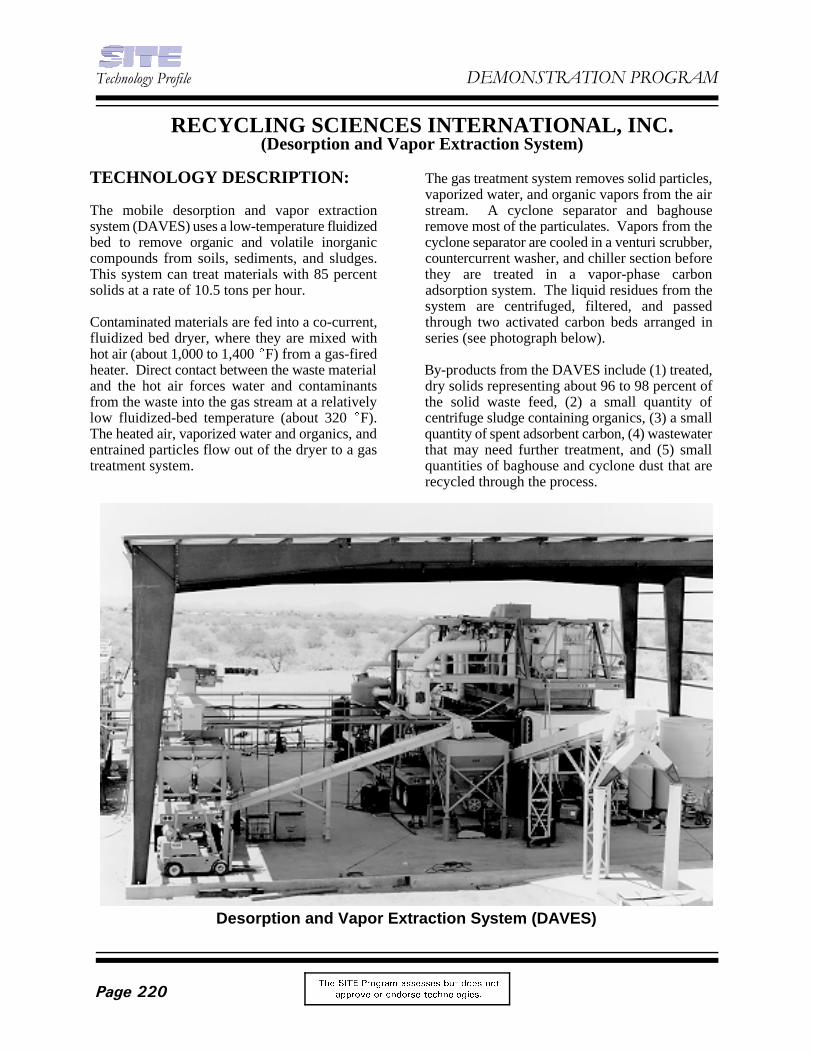
Desorption and Vapor Extraction System (DAVES)
RECYCLING SCIENCES INTERNATIONAL, INC.(Desorption and Vapor Extraction System)
TECHNOLOGY DESCRIPTION: The gas treatment system removes solid particles,
The mobile desorption and vapor extraction stream. A cyclone separator and baghousesystem (DAVES) uses a low-temperature fluidized remove most of the particulates. Vapors from thebed to remove organic and volatile inorganic cyclone separator are cooled in a venturi scrubber,compounds from soils, sediments, and sludges. countercurrent washer, and chiller section beforeThis system can treat materials with 85 percent they are treated in a vapor-phase carbonsolids at a rate of 10.5 tons per hour. adsorption system. The liquid residues from the
Contaminated materials are fed into a co-current, through two activated carbon beds arranged influidized bed dryer, where they are mixed with series (see photograph below).hot air (about 1,000 to 1,400 (F) from a gas-firedheater. Direct contact between the waste material By-products from the DAVES include (1) treated,and the hot air forces water and contaminants dry solids representing about 96 to 98 percent offrom the waste into the gas stream at a relatively the solid waste feed, (2) a small quantity oflow fluidized-bed temperature (about 320 (F). centrifuge sludge containing organics, (3) a smallThe heated air, vaporized water and organics, and quantity of spent adsorbent carbon, (4) wastewaterentrained particles flow out of the dryer to a gas that may need further treatment, and (5) smalltreatment system. quantities of baghouse and cyclone dust that are
vaporized water, and organic vapors from the air
system are centrifuged, filtered, and passed
recycled through the process.
)HEUXDU\�����2QJRLQJ�3URMHFW
7KH 6,7( 3URJUDP DVVHVVHV EXW GRHV QRW
DSSURYH RU HQGRUVH WHFKQRORJLHV� 3DJH����
The centrifuge sludge can be bioremediated, FOR FURTHER INFORMATION:chemically degraded, or treated in anothermanner. Recycling Sciences International, Inc., EPA PROJECT MANAGER:has patented an electrochemical oxidation process Richard Eilers(ECO) and is developing this process as an U.S. EPAadjunct to the DAVES. The ECO is designed to National Risk Management Researchdetoxify contaminants within the DAVES in a Laboratoryclosed-loop system. 26 West Martin Luther King Drive
WASTE APPLICABILITY: 513-569-7809
This technology removes the followingcontaminants from soil, sludge, and sediment: TECHNOLOGY DEVELOPER CONTACT:volatile and semivolatile organics, including William Meenanpolychlorinated biphenyls (PCB), polynuclear Recycling Sciences International, Inc.aromatic hydrocarbons, pentachlorophenol, 175 West Jackson Boulevardvolatile inorganics such as tetraethyl lead, and Suite A1934some pesticides. In general, the process treats Chicago, IL 60604-2601waste containing less than 10 percent total organic 312-663-4242contaminants and 30 to 95 percent solids. The Fax: 312-663-4269presence of nonvolatile inorganic contaminants(such as metals) in the waste feed does not inhibitthe process; however, these contaminants are nottreated.
This technology was accepted into the SITEProgram in April 1995. EPA is selecting ademonstration site for this process. Preferreddemonstration wastes include harbor or riversediments containing at least 50 percent solidscontaminated with PCBs and other volatile orsemivolatile organics. Soils with thesecharacteristics may also be acceptable. About 300tons of waste is needed for a 2-week test. Majortest objectives are to evaluate feed handling,decontamination of solids, and treatment of gasesgenerated by the process.
Cincinnati, OH 45268
Fax: 513-569-7111