Embed Size (px)
Citation preview
1
Arithmetic and LogicInstructions
Arithmetic and LogicInstructions
2
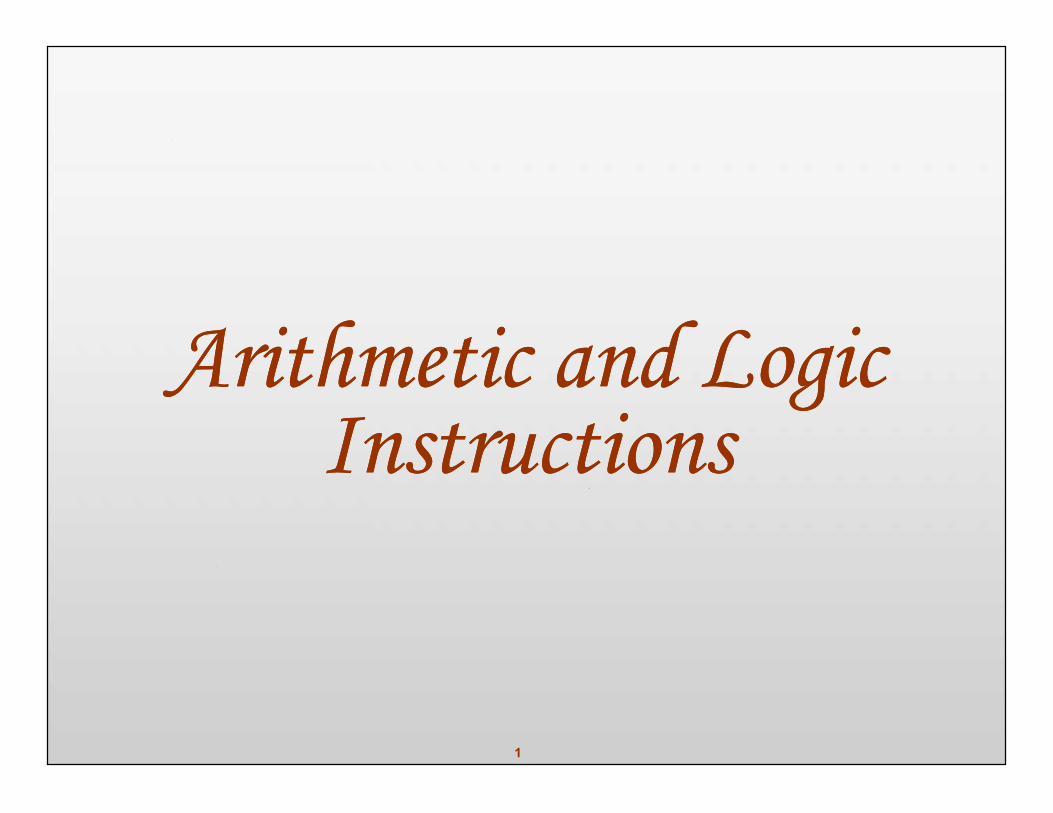
EXAMPLE: ADD / ADC (ver. 1)Write a program to calculate the total sum of 5 bytes of data.Each byte represents the daily wages of a worker.This person does not make more than $255 (FFH) a day.The decimal data is as follows: 125, 235, 197, 91, and 48
COUNT EQU 05DATA DB 125, 235, 197, 91, 48SUM DB ?
… … … … … …MOV CX,COUNTMOV SI, OFFSET DATAMOV AL,00
BACK: ADD AL,[SI]INC SIDEC CXJNZ BACKMOV SUM,ALMOV AH, 4CHINT 21H
3
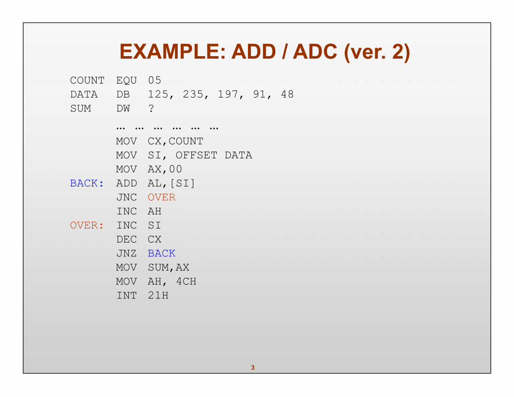
EXAMPLE: ADD / ADC (ver. 2)COUNT EQU 05DATA DB 125, 235, 197, 91, 48SUM DW ?
… … … … … …MOV CX,COUNTMOV SI, OFFSET DATAMOV AX,00
BACK: ADD AL,[SI]JNC OVERINC AH
OVER: INC SIDEC CXJNZ BACKMOV SUM,AXMOV AH, 4CHINT 21H
4
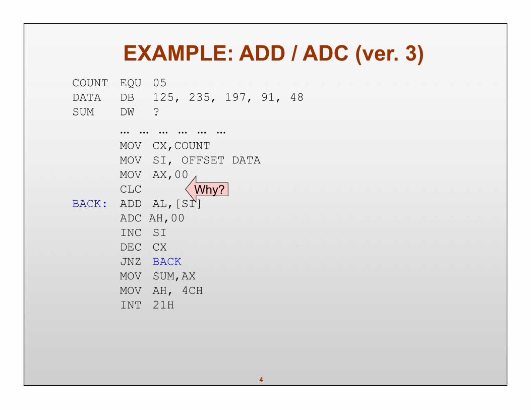
EXAMPLE: ADD / ADC (ver. 3)COUNT EQU 05DATA DB 125, 235, 197, 91, 48SUM DW ?
… … … … … …MOV CX,COUNTMOV SI, OFFSET DATAMOV AX,00CLC
BACK: ADD AL,[SI]ADC AH,00INC SIDEC CXJNZ BACKMOV SUM,AXMOV AH, 4CHINT 21H
Why?
5
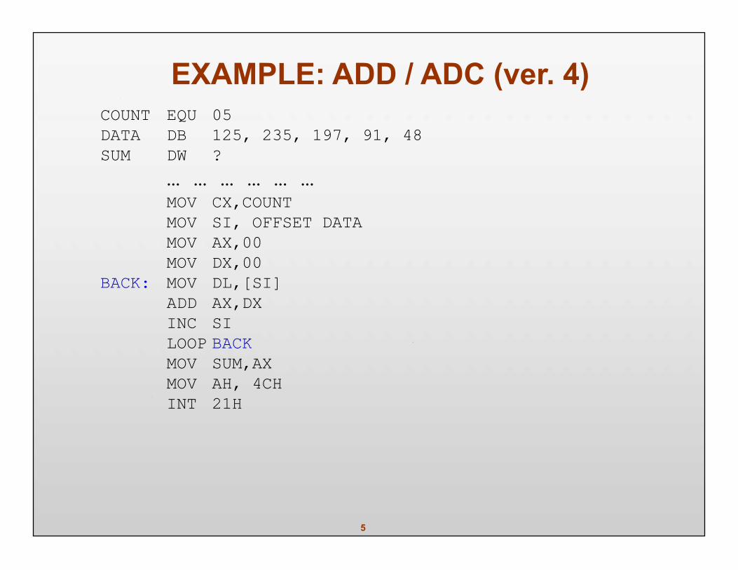
EXAMPLE: ADD / ADC (ver. 4)COUNT EQU 05DATA DB 125, 235, 197, 91, 48SUM DW ?
… … … … … …MOV CX,COUNTMOV SI, OFFSET DATAMOV AX,00MOV DX,00
BACK: MOV DL,[SI]ADD AX,DXINC SILOOP BACKMOV SUM,AXMOV AH, 4CHINT 21H
6
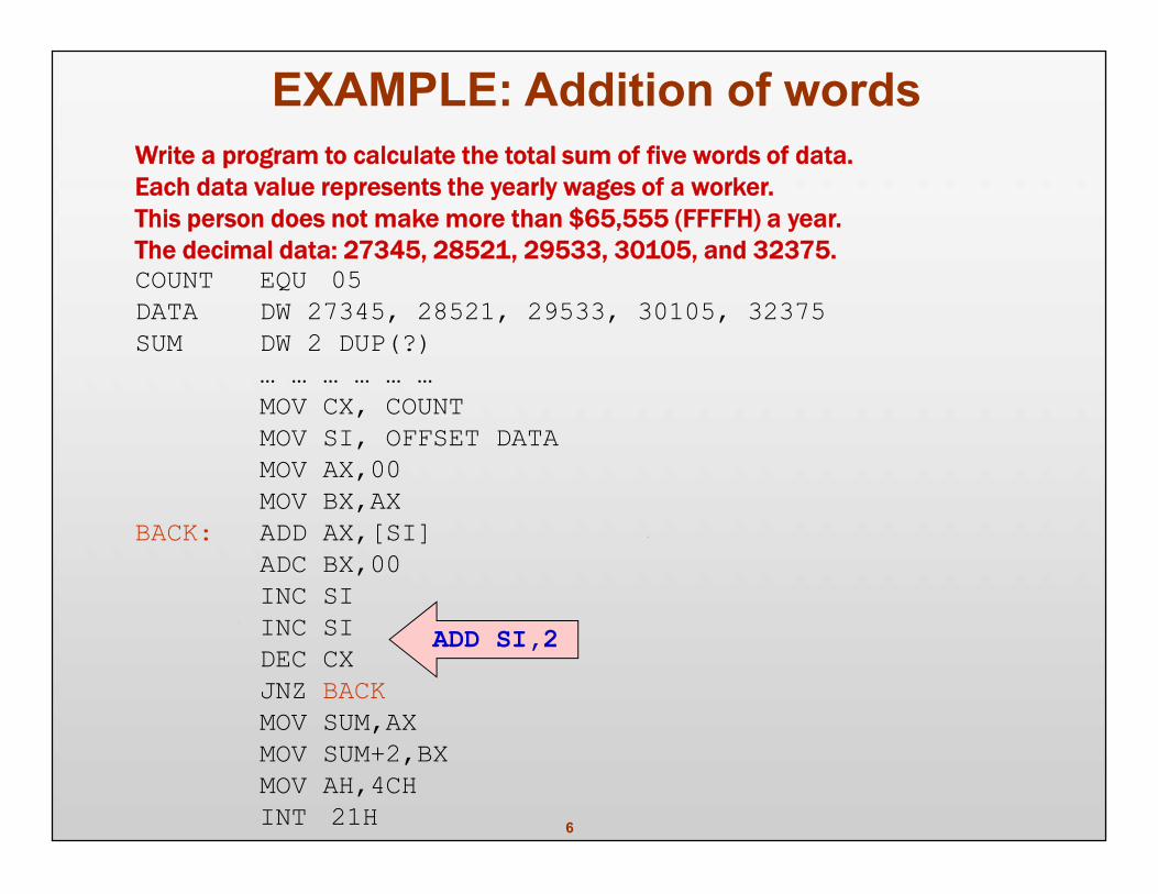
EXAMPLE: Addition of wordsWrite a program to calculate the total sum of five words of data.Each data value represents the yearly wages of a worker.This person does not make more than $65,555 (FFFFH) a year.The decimal data: 27345, 28521, 29533, 30105, and 32375.COUNT EQU 05DATA DW 27345, 28521, 29533, 30105, 32375SUM DW 2 DUP(?)
… … … … … …MOV CX, COUNTMOV SI, OFFSET DATAMOV AX,00MOV BX,AX
BACK: ADD AX,[SI]ADC BX,00INC SIINC SIDEC CXJNZ BACKMOV SUM,AXMOV SUM+2,BXMOV AH,4CHINT 21H
ADD SI,2
7
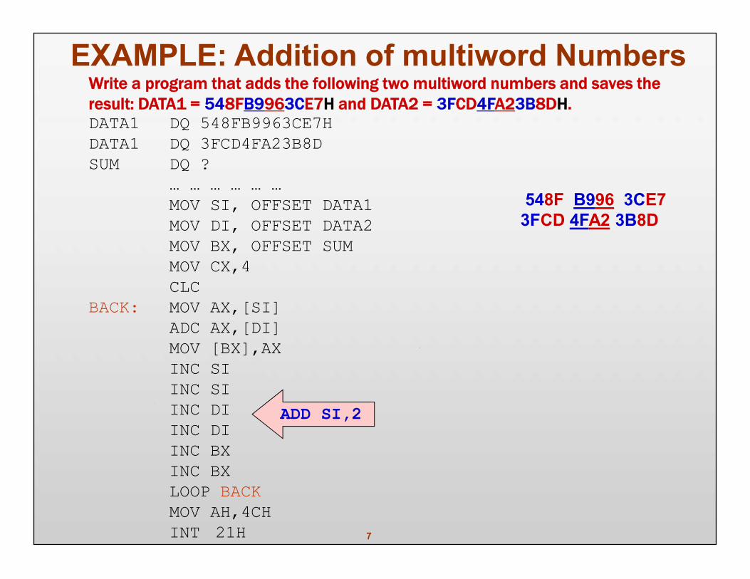
EXAMPLE: Addition of multiword NumbersWrite a program that adds the following two multiword numbers and saves theresult: DATA1 = 548FB9963CE7H and DATA2 = 3FCD4FA23B8DH.DATA1 DQ 548FB9963CE7HDATA1 DQ 3FCD4FA23B8DSUM DQ ?
… … … … … …MOV SI, OFFSET DATA1MOV DI, OFFSET DATA2MOV BX, OFFSET SUMMOV CX,4CLC
BACK: MOV AX,[SI]ADC AX,[DI]MOV [BX],AXINC SIINC SIINC DIINC DIINC BXINC BXLOOP BACKMOV AH,4CHINT 21H
ADD SI,2
548F B996 3CE73FCD 4FA2 3B8D
8
Subtraction of Unsigned Numbers
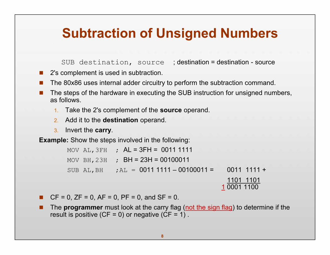
SUB destination, source ; destination = destination - source 2's complement is used in subtraction. The 80x86 uses internal adder circuitry to perform the subtraction command. The steps of the hardware in executing the SUB instruction for unsigned numbers,
as follows.1. Take the 2's complement of the source operand.2. Add it to the destination operand.3. Invert the carry.
Example: Show the steps involved in the following:MOV AL,3FH ; AL = 3FH = 0011 1111MOV BH,23H ; BH = 23H = 00100011SUB AL,BH ;AL = 0011 1111 – 00100011 = 0011 1111 +
1101 11011 0001 1100
CF = 0, ZF = 0, AF = 0, PF = 0, and SF = 0. The programmer must look at the carry flag (not the sign flag) to determine if the
result is positive (CF = 0) or negative (CF = 1) .
9
Example: Analyze the following program
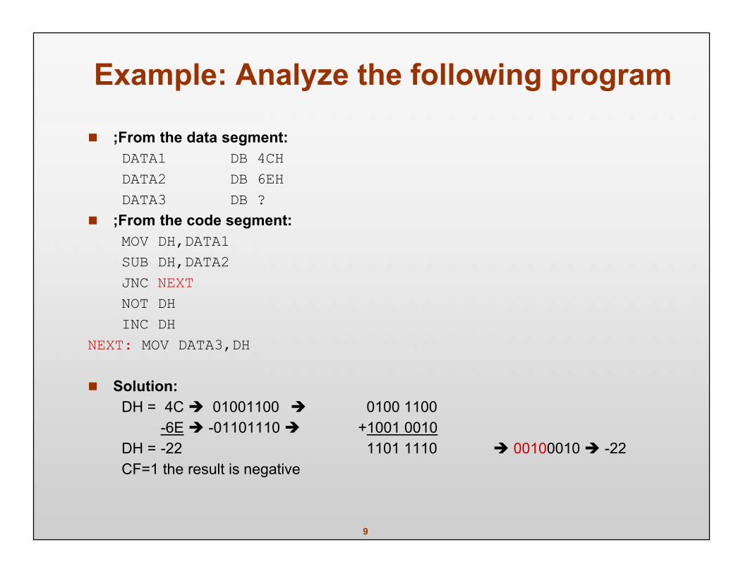
;From the data segment:DATA1 DB 4CHDATA2 DB 6EHDATA3 DB ?
;From the code segment:MOV DH,DATA1SUB DH,DATA2JNC NEXTNOT DHINC DH
NEXT: MOV DATA3,DH
Solution:DH = 4C 01001100 0100 1100
-6E -01101110 +1001 0010DH = -22 1101 1110 00100010 -22CF=1 the result is negative
10
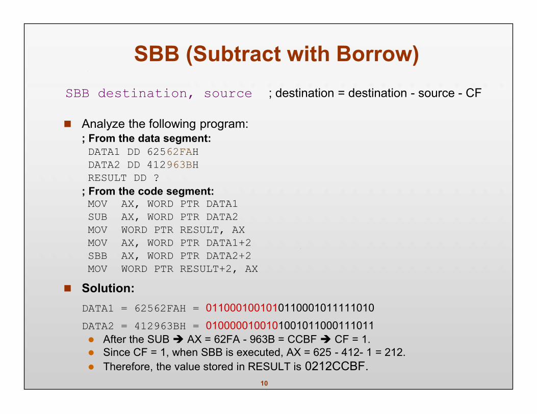
SBB (Subtract with Borrow)SBB destination, source ; destination = destination - source - CF
Analyze the following program:; From the data segment:DATA1 DD 62562FAHDATA2 DD 412963BHRESULT DD ?
; From the code segment:MOV AX, WORD PTR DATA1SUB AX, WORD PTR DATA2MOV WORD PTR RESULT, AXMOV AX, WORD PTR DATA1+2SBB AX, WORD PTR DATA2+2MOV WORD PTR RESULT+2, AX
Solution:DATA1 = 62562FAH = 0110001001010110001011111010DATA2 = 412963BH = 0100000100101001011000111011 After the SUB AX = 62FA - 963B = CCBF CF = 1. Since CF = 1, when SBB is executed, AX = 625 - 412- 1 = 212. Therefore, the value stored in RESULT is 0212CCBF.
11
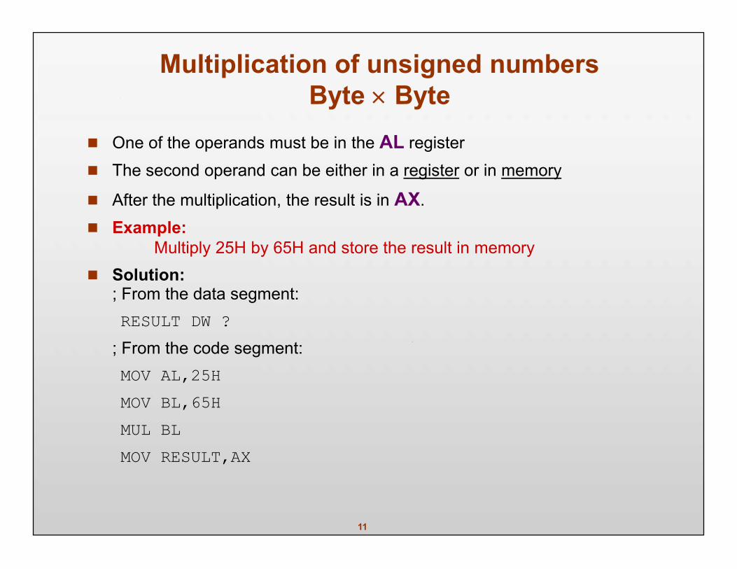
Multiplication of unsigned numbersByte Byte
One of the operands must be in the AL register The second operand can be either in a register or in memory
After the multiplication, the result is in AX. Example:
Multiply 25H by 65H and store the result in memory Solution:
; From the data segment:RESULT DW ?
; From the code segment:MOV AL,25HMOV BL,65HMUL BLMOV RESULT,AX
12
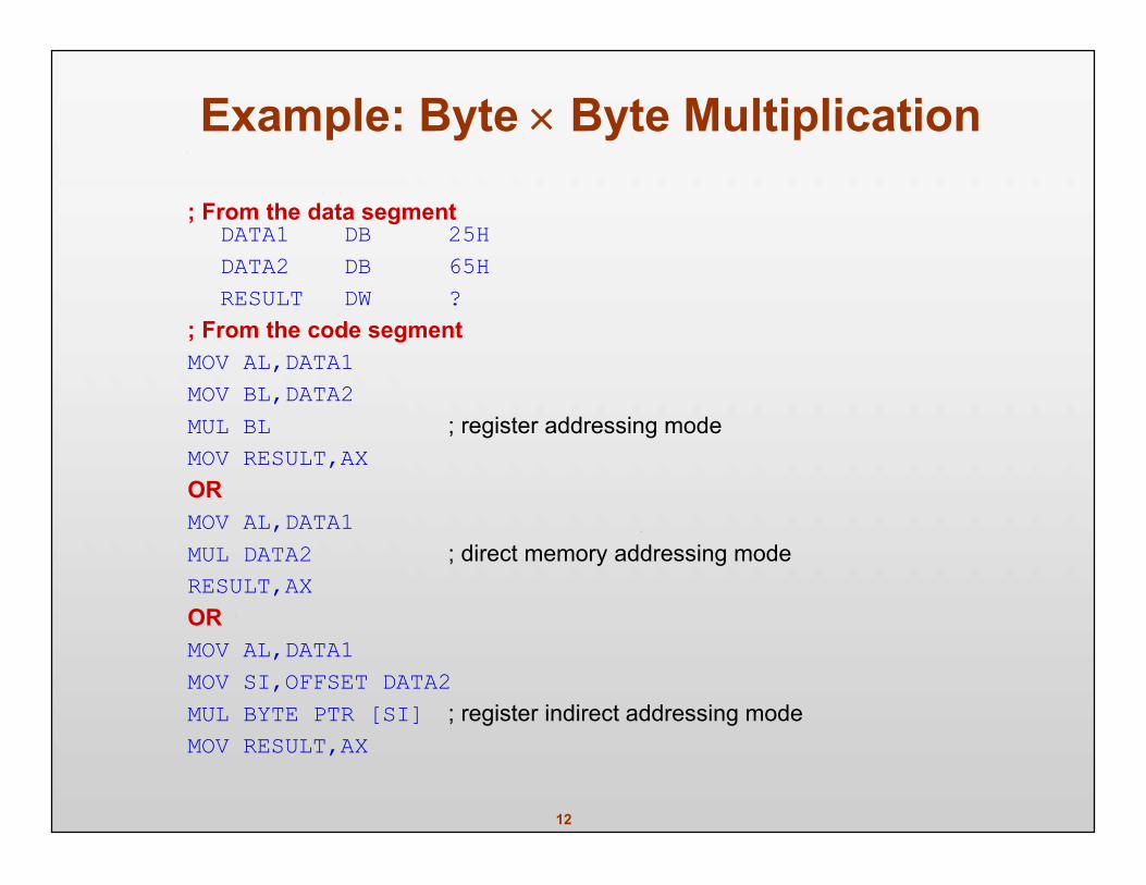
Example: Byte Byte Multiplication
; From the data segmentDATA1 DB 25HDATA2 DB 65HRESULT DW ?
; From the code segmentMOV AL,DATA1MOV BL,DATA2MUL BL ; register addressing modeMOV RESULT,AXORMOV AL,DATA1MUL DATA2 ; direct memory addressing modeRESULT,AXORMOV AL,DATA1MOV SI,OFFSET DATA2MUL BYTE PTR [SI] ; register indirect addressing modeMOV RESULT,AX
13
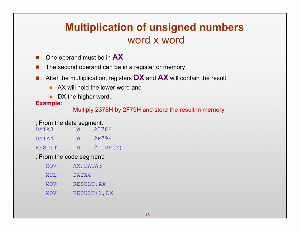
Multiplication of unsigned numbersword x word
One operand must be in AX The second operand can be in a register or memory
After the multiplication, registers DX and AX will contain the result. AX will hold the lower word and DX the higher word.
Example:Multiply 2378H by 2F79H and store the result in memory
; From the data segment:DATA3 DW 2378HDATA4 DW 2F79HRESULT DW 2 DUP(?); From the code segment:
MOV AX,DATA3MUL DATA4MOV RESULT,AXMOV RESULT+2,DX
14
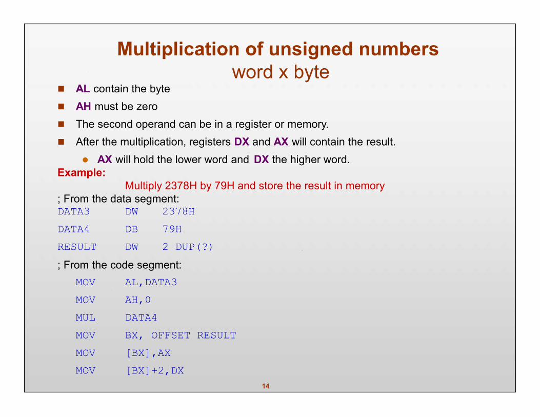
Multiplication of unsigned numbersword x byte
AL contain the byte AH must be zero The second operand can be in a register or memory. After the multiplication, registers DX and AX will contain the result.
AX will hold the lower word and DX the higher word.Example:
Multiply 2378H by 79H and store the result in memory; From the data segment:DATA3 DW 2378HDATA4 DB 79HRESULT DW 2 DUP(?); From the code segment:
MOV AL,DATA3MOV AH,0MUL DATA4MOV BX, OFFSET RESULTMOV [BX],AXMOV [BX]+2,DX
15
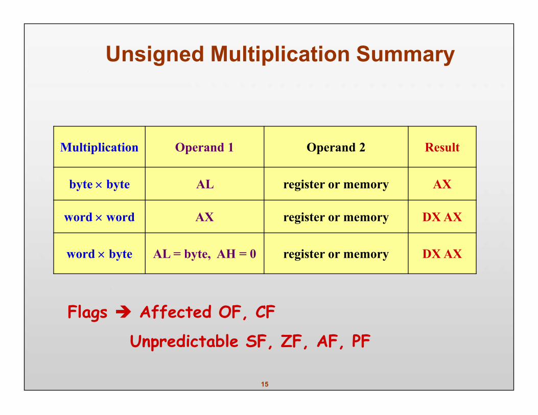
Multiplication Operand 1 Operand 2 Result
byte byte AL register or memory AX
word word AX register or memory DX AX
word byte AL = byte, AH = 0 register or memory DX AX
Unsigned Multiplication Summary
Flags Affected OF, CF
Unpredictable SF, ZF, AF, PF
16
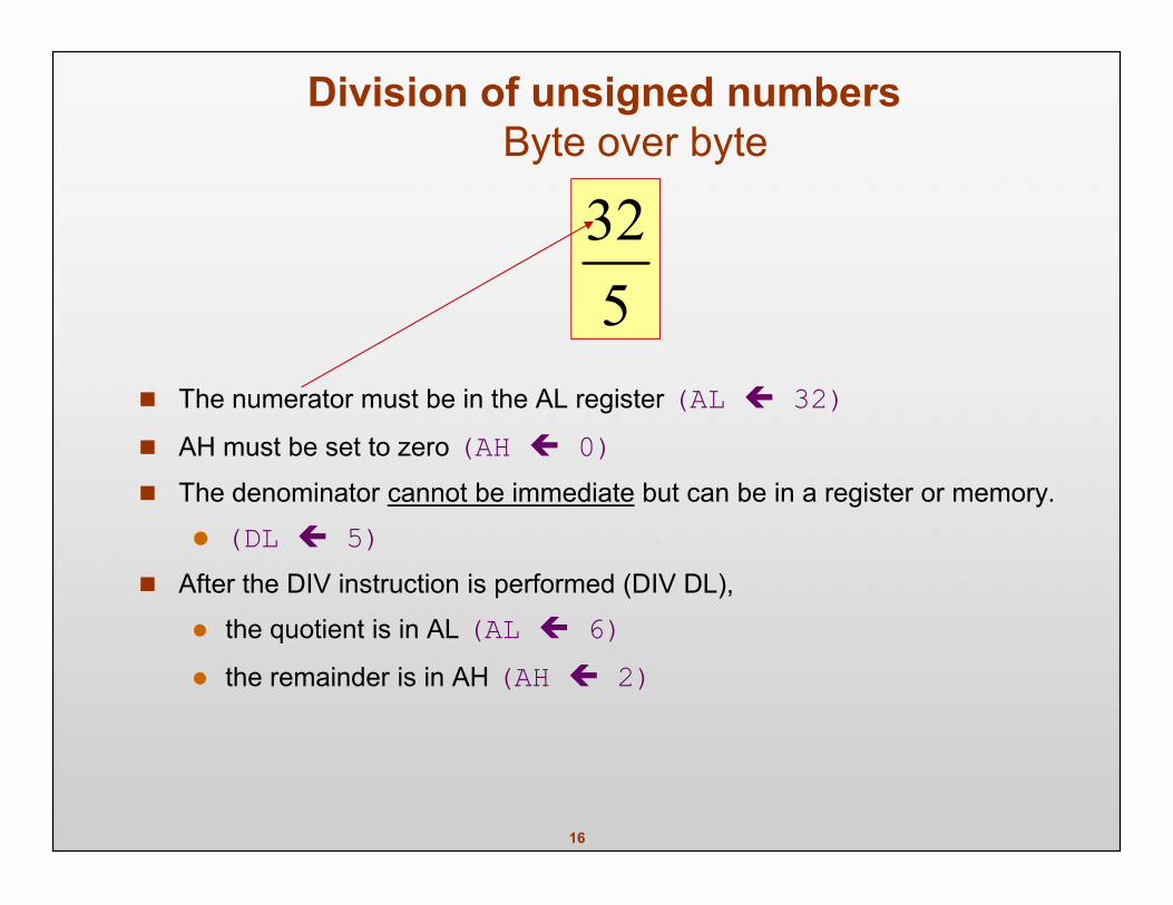
Division of unsigned numbersByte over byte
The numerator must be in the AL register (AL 32) AH must be set to zero (AH 0) The denominator cannot be immediate but can be in a register or memory.
(DL 5) After the DIV instruction is performed (DIV DL),
the quotient is in AL (AL 6) the remainder is in AH (AH 2)
532
17
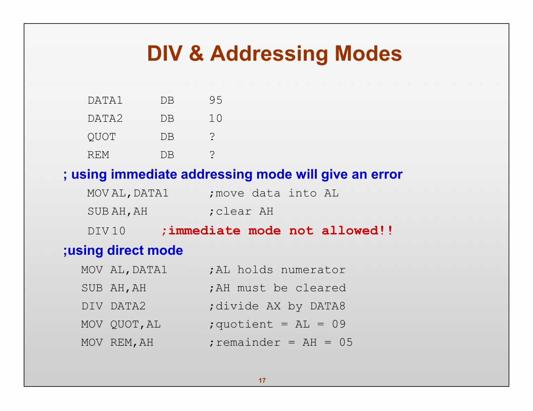
DIV & Addressing Modes
DATA1 DB 95DATA2 DB 10QUOT DB ?REM DB ?
; using immediate addressing mode will give an errorMOV AL,DATA1 ;move data into ALSUB AH,AH ;clear AHDIV 10 ;immediate mode not allowed!!
;using direct modeMOV AL,DATA1 ;AL holds numeratorSUB AH,AH ;AH must be clearedDIV DATA2 ;divide AX by DATA8MOV QUOT,AL ;quotient = AL = 09MOV REM,AH ;remainder = AH = 05
18
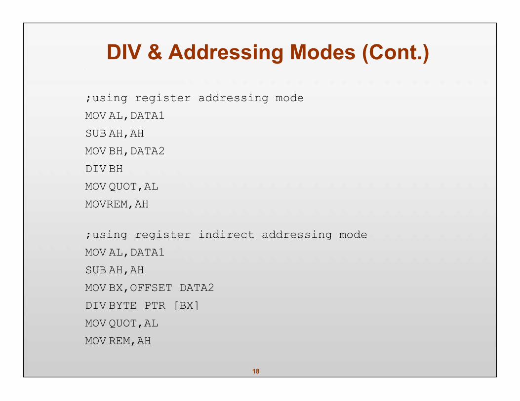
DIV & Addressing Modes (Cont.)
;using register addressing modeMOV AL,DATA1SUB AH,AHMOV BH,DATA2DIV BHMOV QUOT,ALMOVREM,AH
;using register indirect addressing modeMOV AL,DATA1SUB AH,AHMOV BX,OFFSET DATA2DIV BYTE PTR [BX]MOV QUOT,ALMOV REM,AH
19
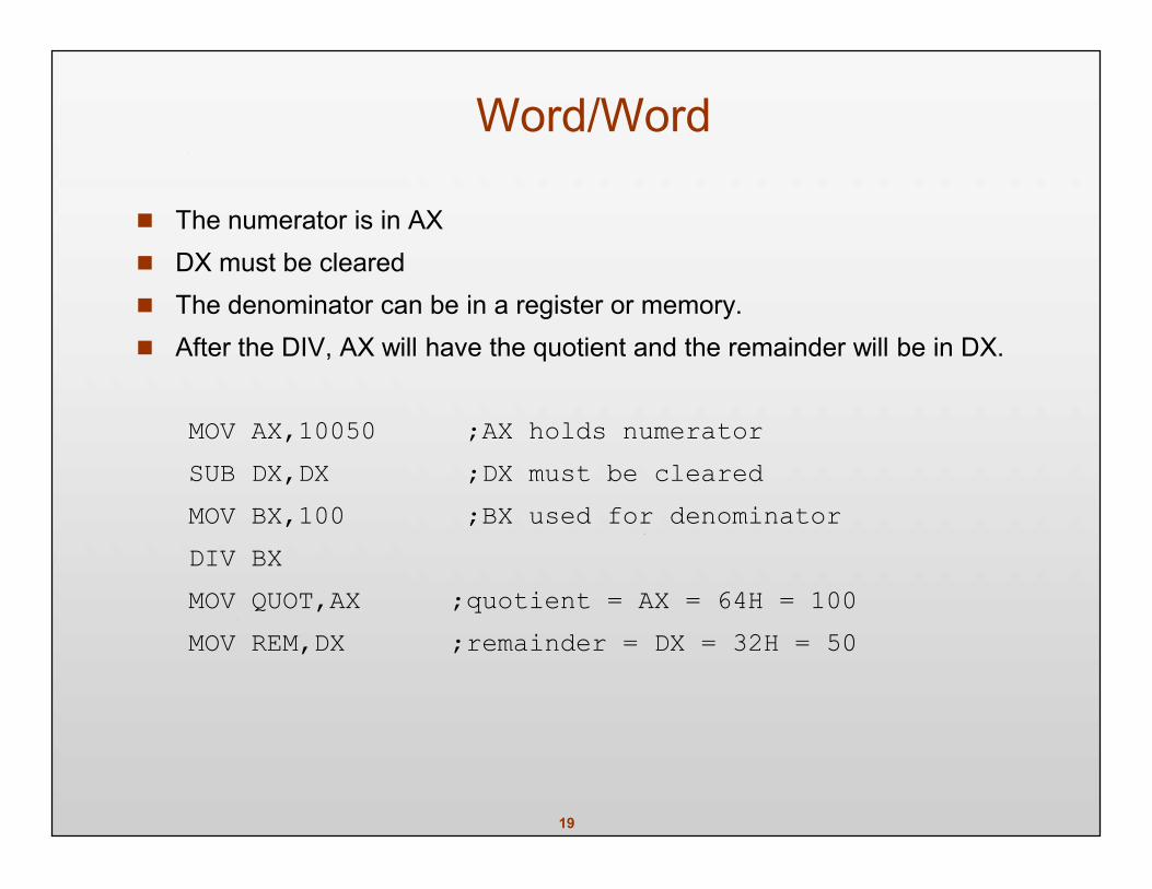
Word/Word
The numerator is in AX DX must be cleared The denominator can be in a register or memory. After the DIV, AX will have the quotient and the remainder will be in DX.
MOV AX,10050 ;AX holds numeratorSUB DX,DX ;DX must be clearedMOV BX,100 ;BX used for denominatorDIV BXMOV QUOT,AX ;quotient = AX = 64H = 100MOV REM,DX ;remainder = DX = 32H = 50
20
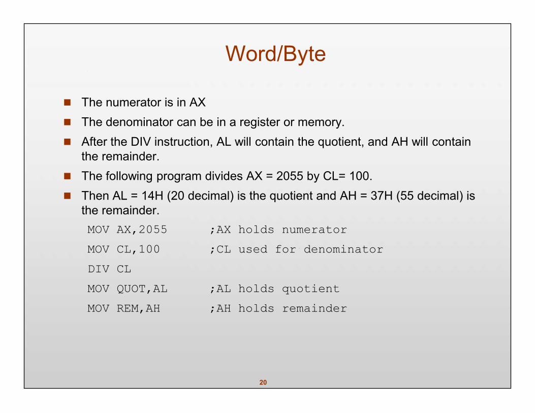
Word/Byte
The numerator is in AX The denominator can be in a register or memory. After the DIV instruction, AL will contain the quotient, and AH will contain
the remainder. The following program divides AX = 2055 by CL= 100. Then AL = 14H (20 decimal) is the quotient and AH = 37H (55 decimal) is
the remainder.MOV AX,2055 ;AX holds numeratorMOV CL,100 ;CL used for denominatorDIV CLMOV QUOT,AL ;AL holds quotientMOV REM,AH ;AH holds remainder
21
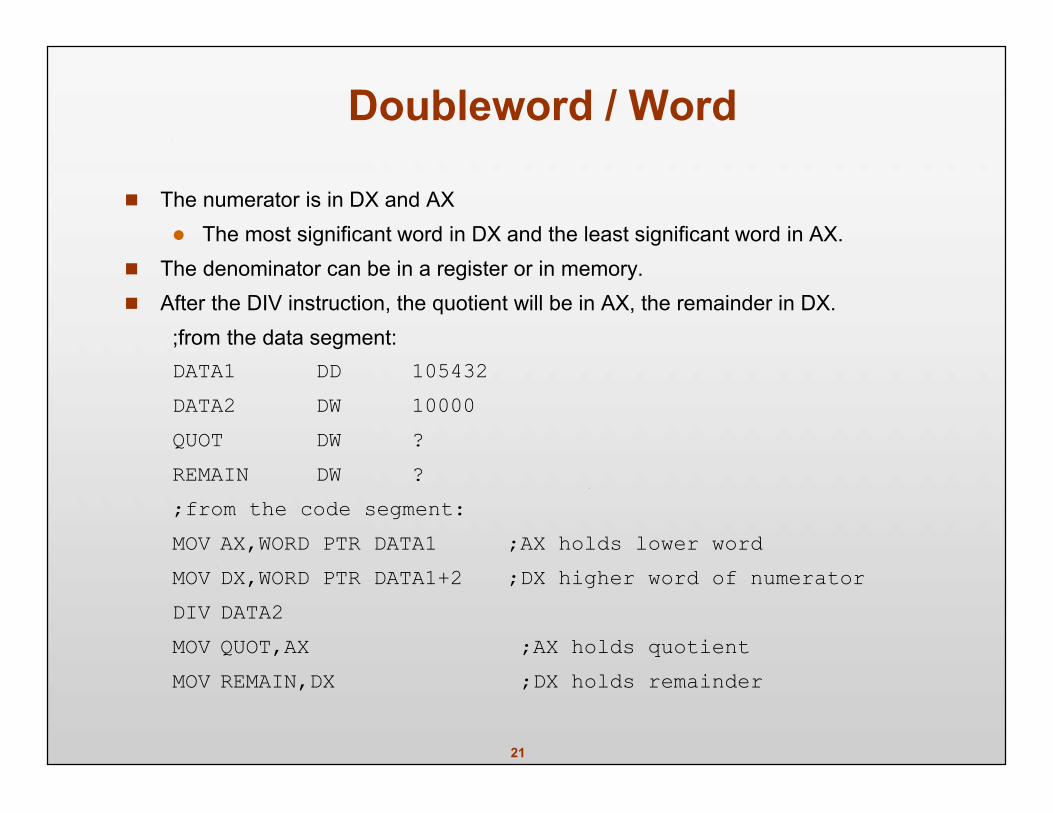
Doubleword / Word
The numerator is in DX and AX The most significant word in DX and the least significant word in AX.
The denominator can be in a register or in memory. After the DIV instruction, the quotient will be in AX, the remainder in DX.
;from the data segment:DATA1 DD 105432DATA2 DW 10000QUOT DW ?REMAIN DW ?;from the code segment:MOV AX,WORD PTR DATA1 ;AX holds lower wordMOV DX,WORD PTR DATA1+2 ;DX higher word of numeratorDIV DATA2MOV QUOT,AX ;AX holds quotientMOV REMAIN,DX ;DX holds remainder
22
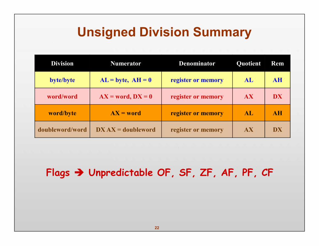
Unsigned Division Summary
Division Numerator Denominator Quotient Rem
byte/byte AL = byte, AH = 0 register or memory AL AH
word/word AX = word, DX = 0 register or memory AX DX
word/byte AX = word register or memory AL AH
doubleword/word DX AX = doubleword register or memory AX DX
Flags Unpredictable OF, SF, ZF, AF, PF, CF
23
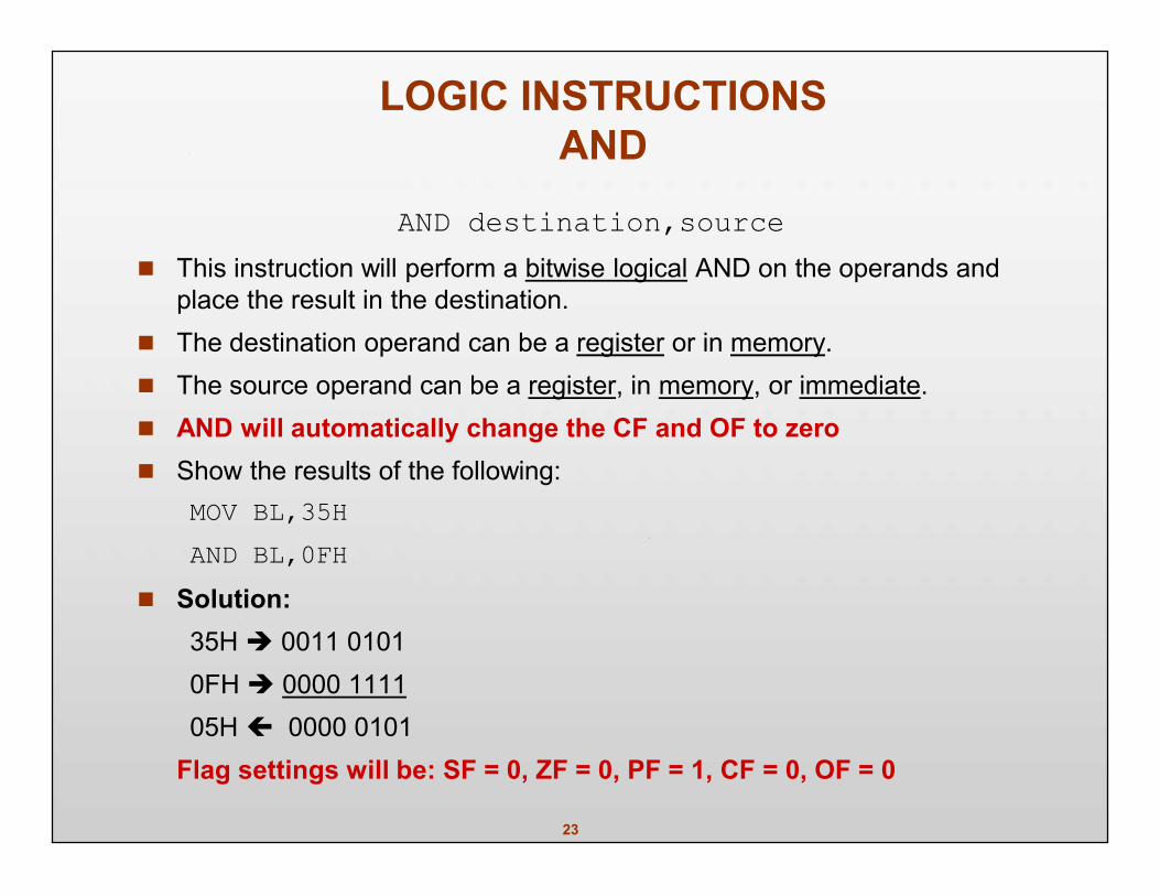
LOGIC INSTRUCTIONSAND
AND destination,source This instruction will perform a bitwise logical AND on the operands and
place the result in the destination. The destination operand can be a register or in memory. The source operand can be a register, in memory, or immediate. AND will automatically change the CF and OF to zero Show the results of the following:
MOV BL,35HAND BL,0FH
Solution:35H 0011 01010FH 0000 111105H 0000 0101
Flag settings will be: SF = 0, ZF = 0, PF = 1, CF = 0, OF = 0
24
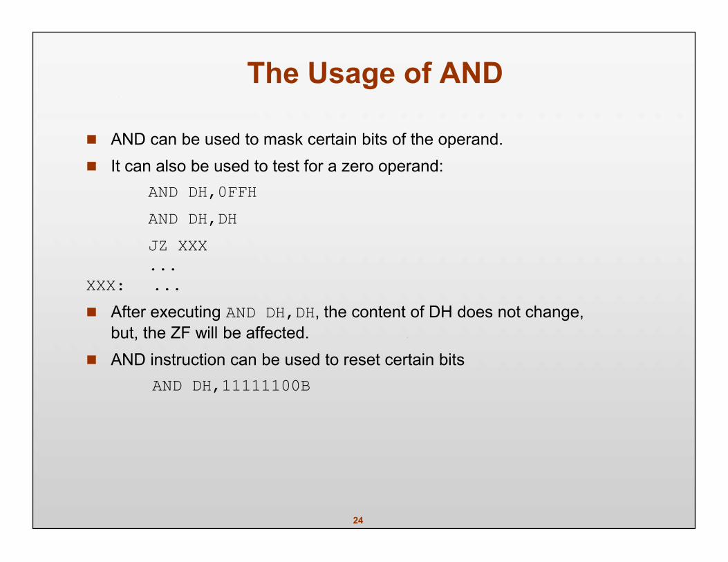
The Usage of AND
AND can be used to mask certain bits of the operand. It can also be used to test for a zero operand:
AND DH,0FFHAND DH,DHJZ XXX...
XXX: ... After executing AND DH,DH, the content of DH does not change,
but, the ZF will be affected. AND instruction can be used to reset certain bits
AND DH,11111100B
25
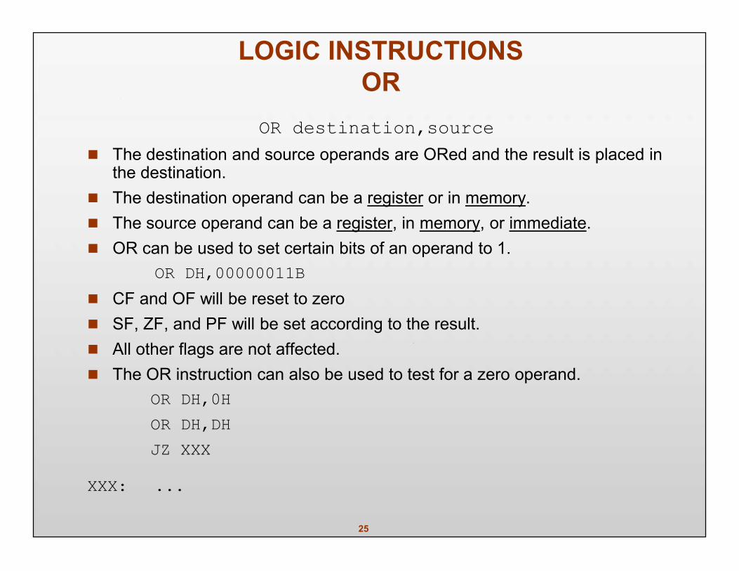
LOGIC INSTRUCTIONSOR
OR destination,source The destination and source operands are ORed and the result is placed in
the destination. The destination operand can be a register or in memory. The source operand can be a register, in memory, or immediate. OR can be used to set certain bits of an operand to 1.
OR DH,00000011B CF and OF will be reset to zero SF, ZF, and PF will be set according to the result. All other flags are not affected. The OR instruction can also be used to test for a zero operand.
OR DH,0HOR DH,DHJZ XXX
XXX: ...
26
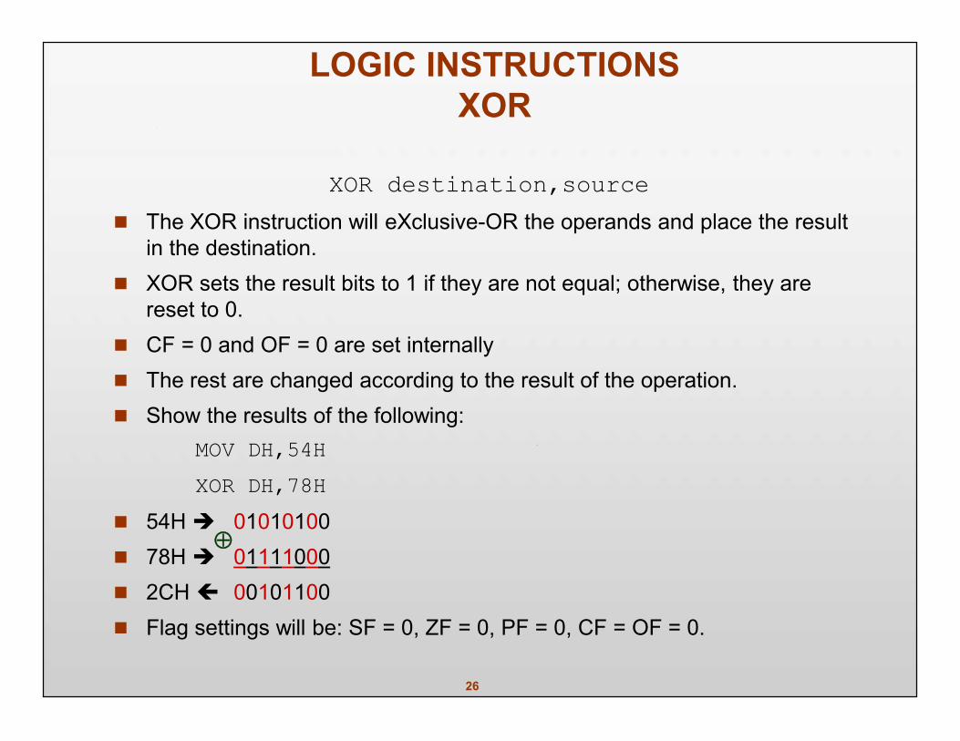
LOGIC INSTRUCTIONSXOR
XOR destination,source The XOR instruction will eXclusive-OR the operands and place the result
in the destination. XOR sets the result bits to 1 if they are not equal; otherwise, they are
reset to 0. CF = 0 and OF = 0 are set internally The rest are changed according to the result of the operation. Show the results of the following:
MOV DH,54HXOR DH,78H
54H 01010100 78H 01111000 2CH 00101100 Flag settings will be: SF = 0, ZF = 0, PF = 0, CF = OF = 0.
27
SHIFT
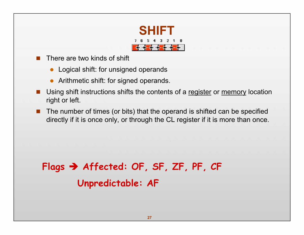
There are two kinds of shift Logical shift: for unsigned operands Arithmetic shift: for signed operands.
Using shift instructions shifts the contents of a register or memory locationright or left.
The number of times (or bits) that the operand is shifted can be specifieddirectly if it is once only, or through the CL register if it is more than once.
Flags Affected: OF, SF, ZF, PF, CF
Unpredictable: AF
28
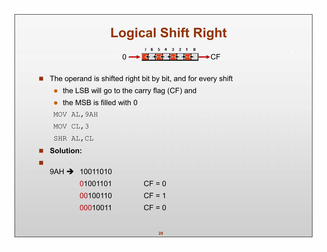
Logical Shift Right
The operand is shifted right bit by bit, and for every shift the LSB will go to the carry flag (CF) and the MSB is filled with 0MOV AL,9AHMOV CL,3SHR AL,CL
Solution:
9AH 1001101001001101 CF = 000100110 CF = 100010011 CF = 0
0 CF
29
Logical Shift Right (Cont.)
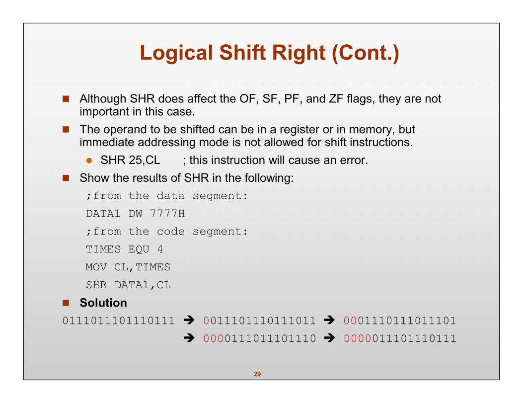
Although SHR does affect the OF, SF, PF, and ZF flags, they are notimportant in this case.
The operand to be shifted can be in a register or in memory, butimmediate addressing mode is not allowed for shift instructions. SHR 25,CL ; this instruction will cause an error.
Show the results of SHR in the following:;from the data segment:DATA1 DW 7777H;from the code segment:TIMES EQU 4MOV CL,TIMESSHR DATA1,CL
Solution0111011101110111 0011101110111011 0001110111011101
0000111011101110 0000011101110111
30
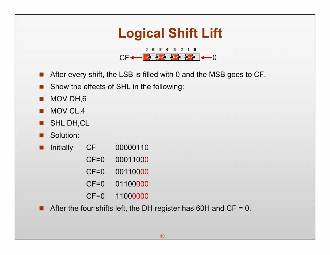
Logical Shift Lift
After every shift, the LSB is filled with 0 and the MSB goes to CF. Show the effects of SHL in the following: MOV DH,6 MOV CL,4 SHL DH,CL Solution: Initially CF 00000110
CF=0 00011000CF=0 00110000CF=0 01100000CF=0 11000000
After the four shifts left, the DH register has 60H and CF = 0.
CF 0
31
COMPARE of unsigned numbers
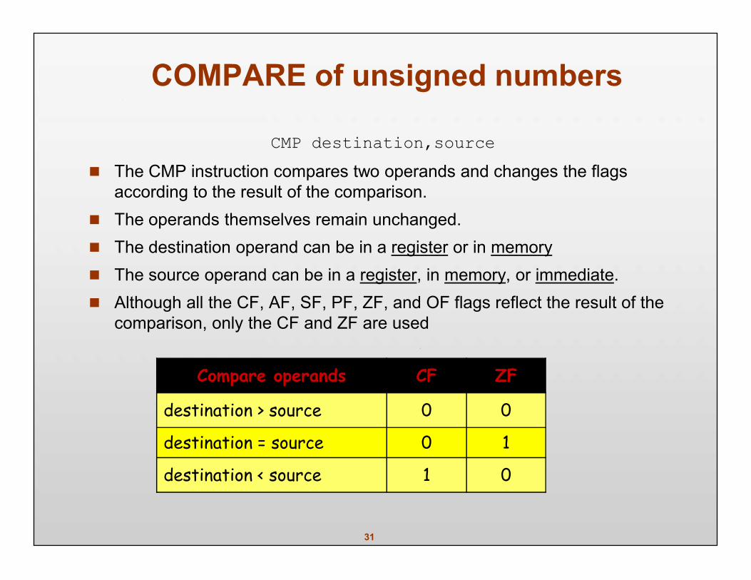
CMP destination,source The CMP instruction compares two operands and changes the flags
according to the result of the comparison. The operands themselves remain unchanged. The destination operand can be in a register or in memory The source operand can be in a register, in memory, or immediate. Although all the CF, AF, SF, PF, ZF, and OF flags reflect the result of the
comparison, only the CF and ZF are used
Compare operands CF ZF
destination > source 0 0
destination = source 0 1
destination < source 1 0
32
Unsigned J instructions
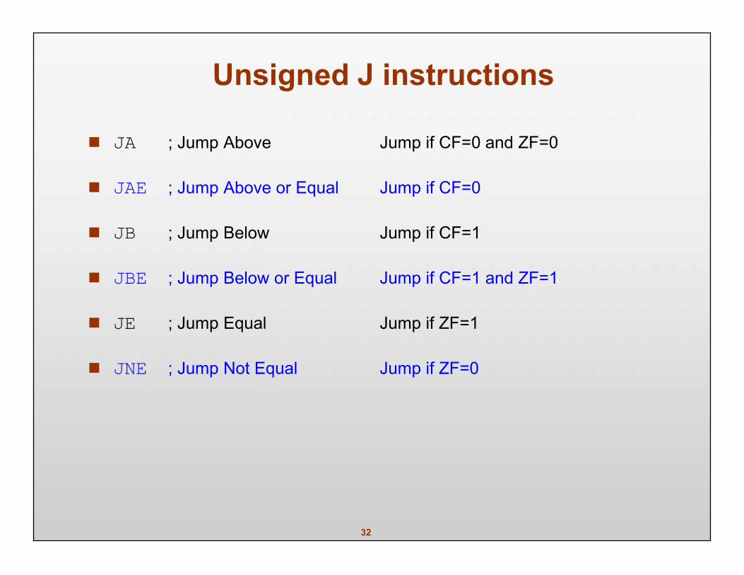
JA ; Jump Above Jump if CF=0 and ZF=0
JAE ; Jump Above or Equal Jump if CF=0
JB ; Jump Below Jump if CF=1
JBE ; Jump Below or Equal Jump if CF=1 and ZF=1
JE ; Jump Equal Jump if ZF=1
JNE ; Jump Not Equal Jump if ZF=0
33
ROTATE INSTRUCTIONS
The rotation instructions ROR, ROL and RCR, RCL are designedspecifically to perform a bitwise rotation of an operand.
They allow a program to rotate an operand right or left. The operand can be in a register or memory. If the number of times an operand is to be rotated is more than 1, this is
indicated by CL. (This is similar to the shift instructions.)
Flags Affected: OF, CF
34
ROR rotate right
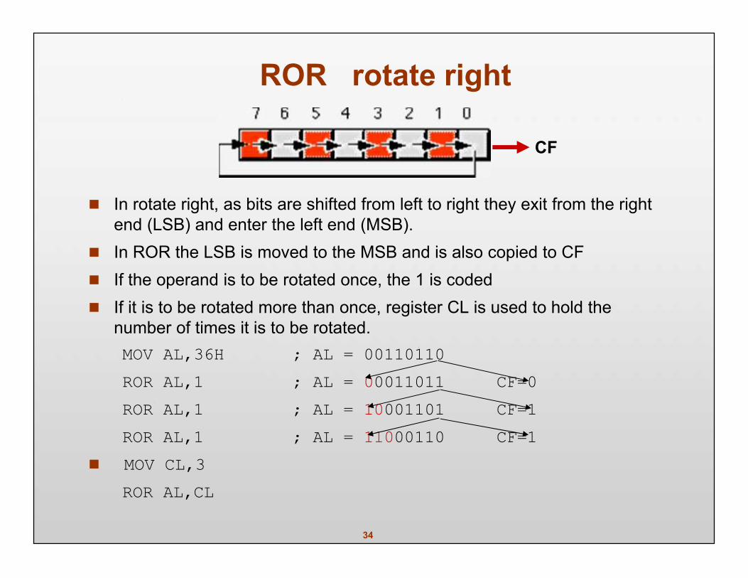
In rotate right, as bits are shifted from left to right they exit from the rightend (LSB) and enter the left end (MSB).
In ROR the LSB is moved to the MSB and is also copied to CF If the operand is to be rotated once, the 1 is coded If it is to be rotated more than once, register CL is used to hold the
number of times it is to be rotated.MOV AL,36H ; AL = 00110110ROR AL,1 ; AL = 00011011 CF=0ROR AL,1 ; AL = 10001101 CF=1ROR AL,1 ; AL = 11000110 CF=1
MOV CL,3ROR AL,CL
CF
35
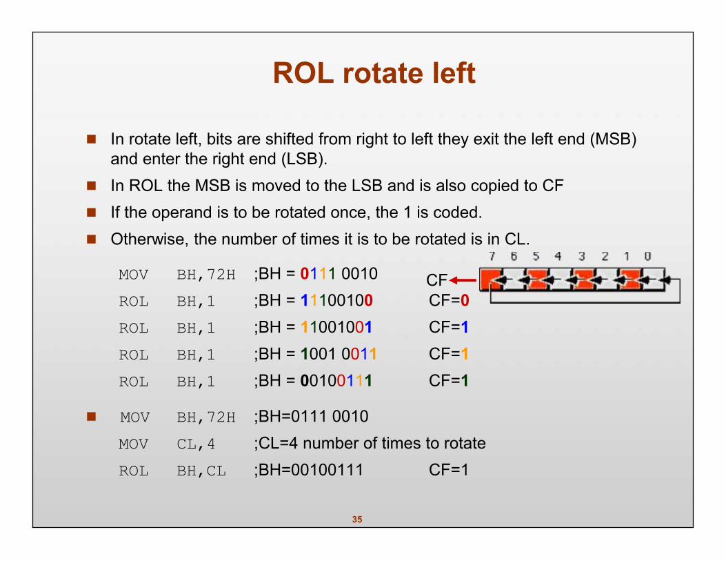
ROL rotate left
In rotate left, bits are shifted from right to left they exit the left end (MSB)and enter the right end (LSB).
In ROL the MSB is moved to the LSB and is also copied to CF If the operand is to be rotated once, the 1 is coded. Otherwise, the number of times it is to be rotated is in CL.
MOV BH,72H ;BH = 0111 0010ROL BH,1 ;BH = 11100100 CF=0ROL BH,1 ;BH = 11001001 CF=1ROL BH,1 ;BH = 1001 0011 CF=1ROL BH,1 ;BH = 00100111 CF=1
MOV BH,72H ;BH=0111 0010MOV CL,4 ;CL=4 number of times to rotateROL BH,CL ;BH=00100111 CF=1
CF
36
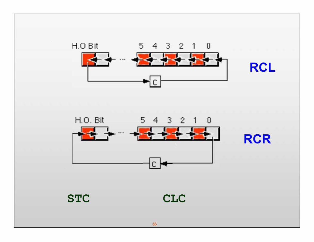
RCL
RCR
STC CLC
37
BCD, ASCII, and ControlInstructions
BCD, ASCII, and ControlInstructions
38
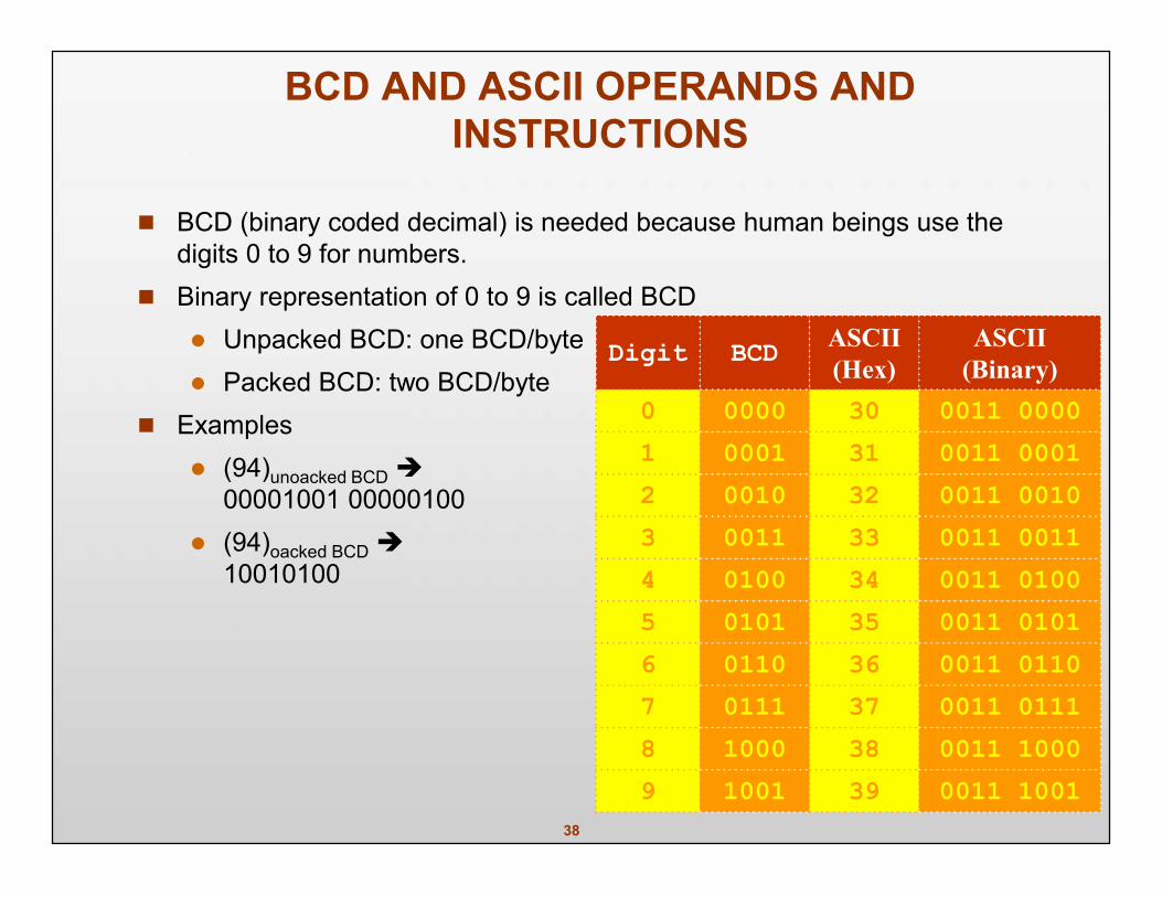
BCD AND ASCII OPERANDS ANDINSTRUCTIONS
BCD (binary coded decimal) is needed because human beings use thedigits 0 to 9 for numbers.
Binary representation of 0 to 9 is called BCD Unpacked BCD: one BCD/byte Packed BCD: two BCD/byte
Examples (94)unoacked BCD
00001001 00000100 (94)oacked BCD
10010100
Digit BCD ASCII(Hex)
ASCII(Binary)
0 0000 30 0011 00001 0001 31 0011 00012 0010 32 0011 00103 0011 33 0011 00114 0100 34 0011 01005 0101 35 0011 01016 0110 36 0011 01107 0111 37 0011 01118 1000 38 0011 10009 1001 39 0011 1001
39
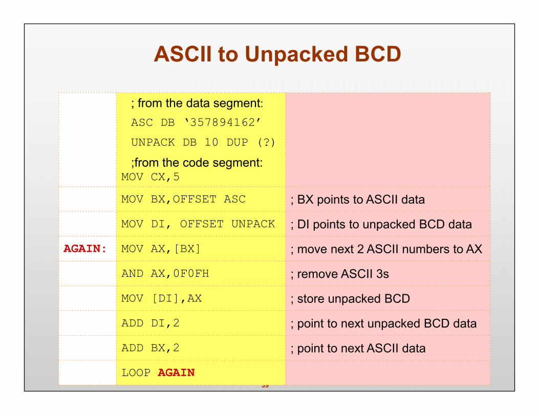
ASCII to Unpacked BCD
; from the data segment:ASC DB ‘357894162’UNPACK DB 10 DUP (?);from the code segment:
MOV CX,5MOV BX,OFFSET ASC ; BX points to ASCII data
MOV DI, OFFSET UNPACK ; DI points to unpacked BCD data
AGAIN: MOV AX,[BX] ; move next 2 ASCII numbers to AX
AND AX,0F0FH ; remove ASCII 3s
MOV [DI],AX ; store unpacked BCD
ADD DI,2 ; point to next unpacked BCD data
ADD BX,2 ; point to next ASCII data
LOOP AGAIN
40
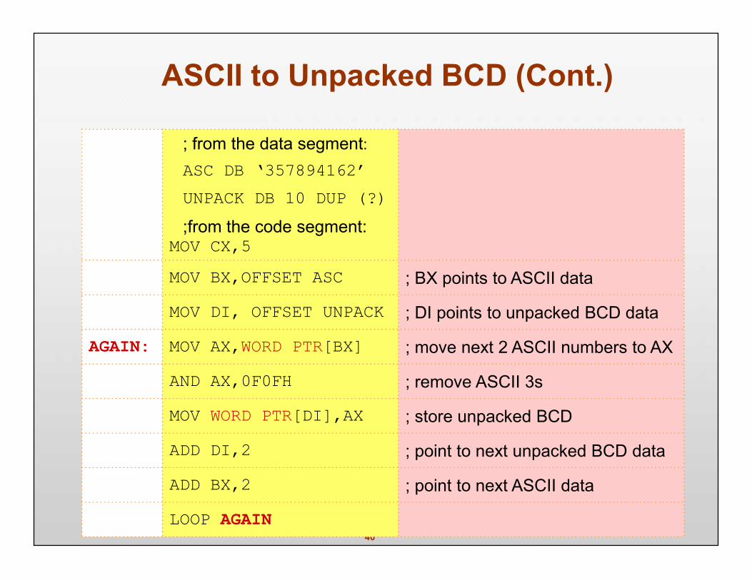
ASCII to Unpacked BCD (Cont.)
; from the data segment:ASC DB ‘357894162’UNPACK DB 10 DUP (?);from the code segment:
MOV CX,5MOV BX,OFFSET ASC ; BX points to ASCII data
MOV DI, OFFSET UNPACK ; DI points to unpacked BCD data
AGAIN: MOV AX,WORD PTR[BX] ; move next 2 ASCII numbers to AX
AND AX,0F0FH ; remove ASCII 3s
MOV WORD PTR[DI],AX ; store unpacked BCD
ADD DI,2 ; point to next unpacked BCD data
ADD BX,2 ; point to next ASCII data
LOOP AGAIN
41
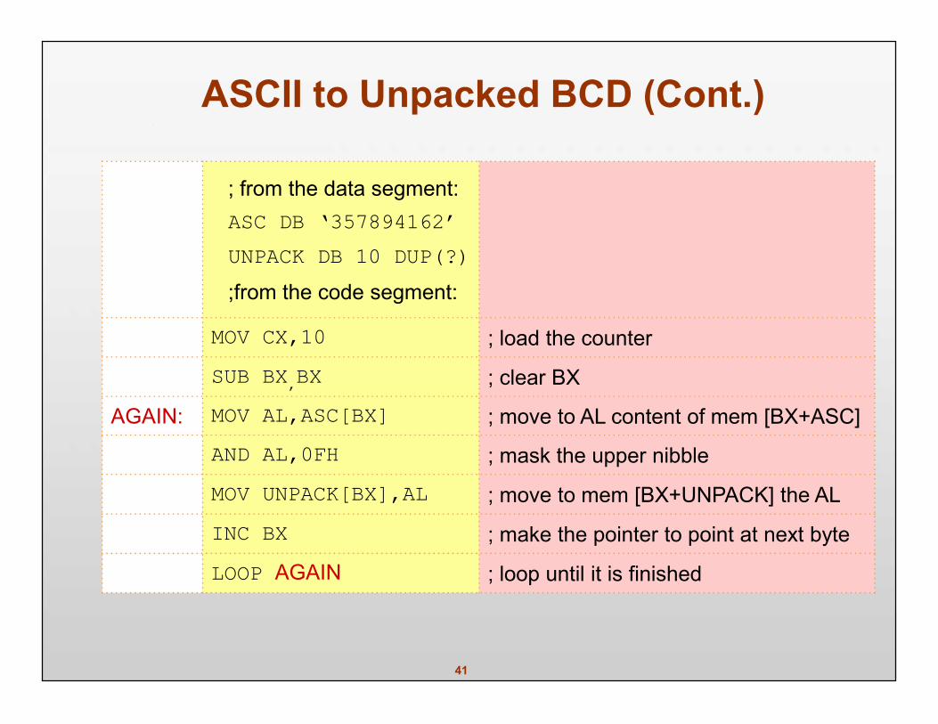
ASCII to Unpacked BCD (Cont.)
; from the data segment:ASC DB ‘357894162’UNPACK DB 10 DUP(?);from the code segment:
MOV CX,10 ; load the counter
SUB BX,BX ; clear BX
AGAIN: MOV AL,ASC[BX] ; move to AL content of mem [BX+ASC]
AND AL,0FH ; mask the upper nibble
MOV UNPACK[BX],AL ; move to mem [BX+UNPACK] the AL
INC BX ; make the pointer to point at next byte
LOOP AGAIN ; loop until it is finished
42
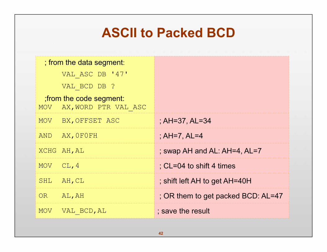
ASCII to Packed BCD
; from the data segment:VAL_ASC DB '47'VAL_BCD DB ?
;from the code segment:MOV AX,WORD PTR VAL_ASCMOV BX,OFFSET ASC ; AH=37, AL=34
AND AX,0F0FH ; AH=7, AL=4
XCHG AH,AL ; swap AH and AL: AH=4, AL=7
MOV CL,4 ; CL=04 to shift 4 times
SHL AH,CL ; shift left AH to get AH=40H
OR AL,AH ; OR them to get packed BCD: AL=47
MOV VAL_BCD,AL ; save the result
43
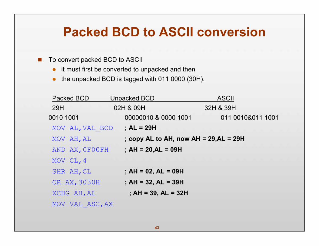
Packed BCD to ASCII conversion
To convert packed BCD to ASCII it must first be converted to unpacked and then the unpacked BCD is tagged with 011 0000 (30H).
Packed BCD Unpacked BCD ASCII29H 02H & 09H 32H & 39H
0010 1001 00000010 & 0000 1001 011 0010&011 1001MOV AL,VAL_BCD ; AL = 29HMOV AH,AL ; copy AL to AH, now AH = 29,AL = 29HAND AX,0F00FH ; AH = 20,AL = 09HMOV CL,4SHR AH,CL ; AH = 02, AL = 09HOR AX,3030H ; AH = 32, AL = 39HXCHG AH,AL ; AH = 39, AL = 32HMOV VAL_ASC,AX
44
BCD addition and correction
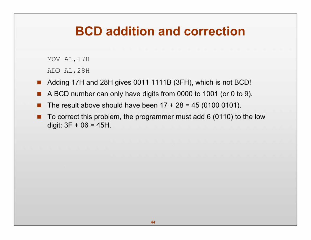
MOV AL,17HADD AL,28H
Adding 17H and 28H gives 0011 1111B (3FH), which is not BCD! A BCD number can only have digits from 0000 to 1001 (or 0 to 9). The result above should have been 17 + 28 = 45 (0100 0101). To correct this problem, the programmer must add 6 (0110) to the low
digit: 3F + 06 = 45H.
45
DAA (Decimal Adjust for Addition) Instruction
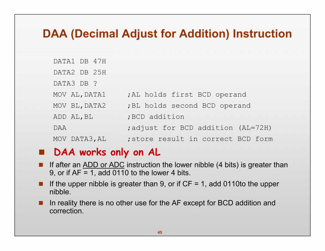
DATA1 DB 47HDATA2 DB 25HDATA3 DB ?MOV AL,DATA1 ;AL holds first BCD operandMOV BL,DATA2 ;BL holds second BCD operandADD AL,BL ;BCD additionDAA ;adjust for BCD addition (AL=72H)MOV DATA3,AL ;store result in correct BCD form
DAA works only on AL If after an ADD or ADC instruction the lower nibble (4 bits) is greater than
9, or if AF = 1, add 0110 to the lower 4 bits. If the upper nibble is greater than 9, or if CF = 1, add 0110to the upper
nibble. In reality there is no other use for the AF except for BCD addition and
correction.
46
BCD subtraction and correction
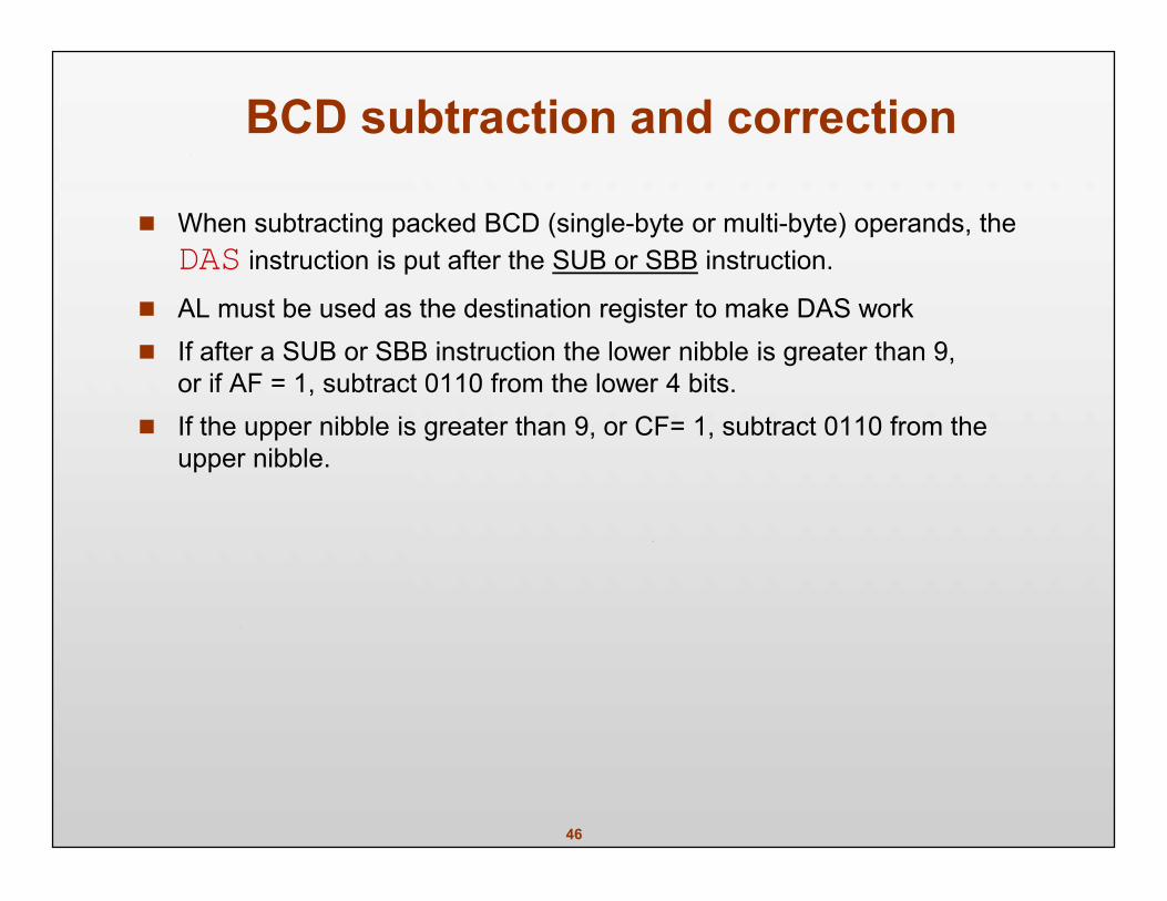
When subtracting packed BCD (single-byte or multi-byte) operands, theDAS instruction is put after the SUB or SBB instruction.
AL must be used as the destination register to make DAS work If after a SUB or SBB instruction the lower nibble is greater than 9,
or if AF = 1, subtract 0110 from the lower 4 bits. If the upper nibble is greater than 9, or CF= 1, subtract 0110 from the
upper nibble.
47
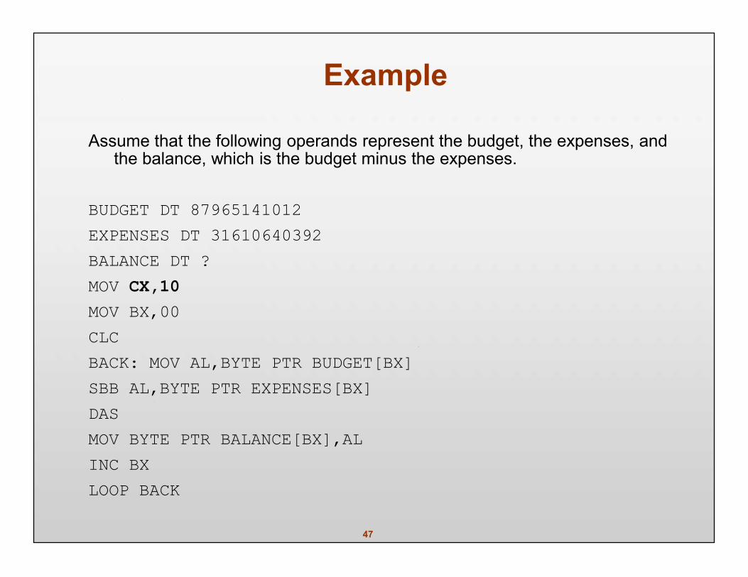
Example
Assume that the following operands represent the budget, the expenses, andthe balance, which is the budget minus the expenses.
BUDGET DT 87965141012EXPENSES DT 31610640392BALANCE DT ?MOV CX,10MOV BX,00CLCBACK: MOV AL,BYTE PTR BUDGET[BX]SBB AL,BYTE PTR EXPENSES[BX]DASMOV BYTE PTR BALANCE[BX],ALINC BXLOOP BACK
48
ASCII addition
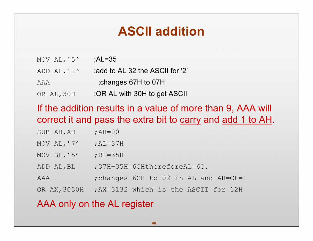
MOV AL,'5‘ ;AL=35ADD AL,'2‘ ;add to AL 32 the ASCII for ‘2’AAA ;changes 67H to 07HOR AL,30H ;OR AL with 30H to get ASCII
If the addition results in a value of more than 9, AAA willcorrect it and pass the extra bit to carry and add 1 to AH.SUB AH,AH ;AH=00MOV AL,’7’ ;AL=37HMOV BL,’5’ ;BL=35HADD AL,BL ;37H+35H=6CHthereforeAL=6C.AAA ;changes 6CH to 02 in AL and AH=CF=1OR AX,3030H ;AX=3132 which is the ASCII for 12H
AAA only on the AL register
49
ASCII subtraction
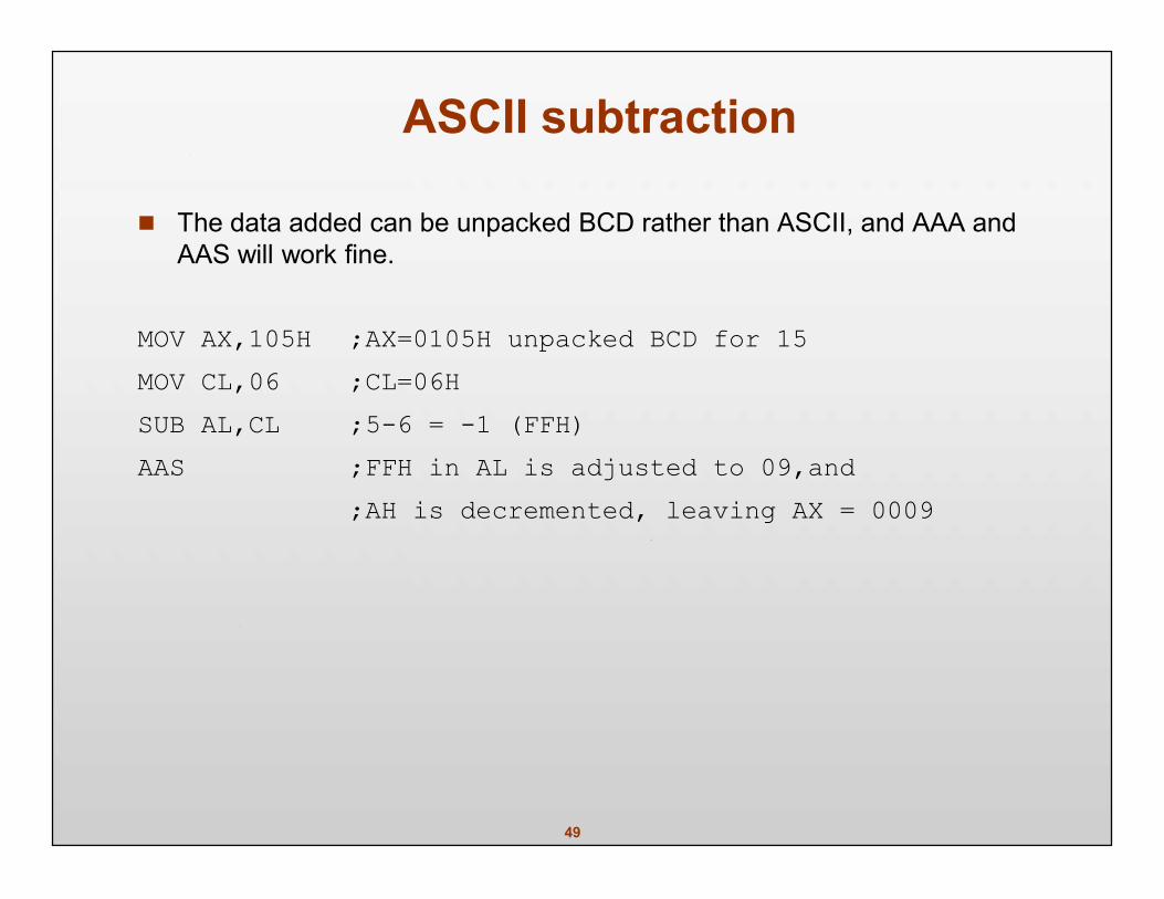
The data added can be unpacked BCD rather than ASCII, and AAA andAAS will work fine.
MOV AX,105H ;AX=0105H unpacked BCD for 15MOV CL,06 ;CL=06HSUB AL,CL ;5-6 = -1 (FFH)AAS ;FFH in AL is adjusted to 09,and
;AH is decremented, leaving AX = 0009
50
Unpacked BCD multiplicationAAM: ASCII adjust multiplication
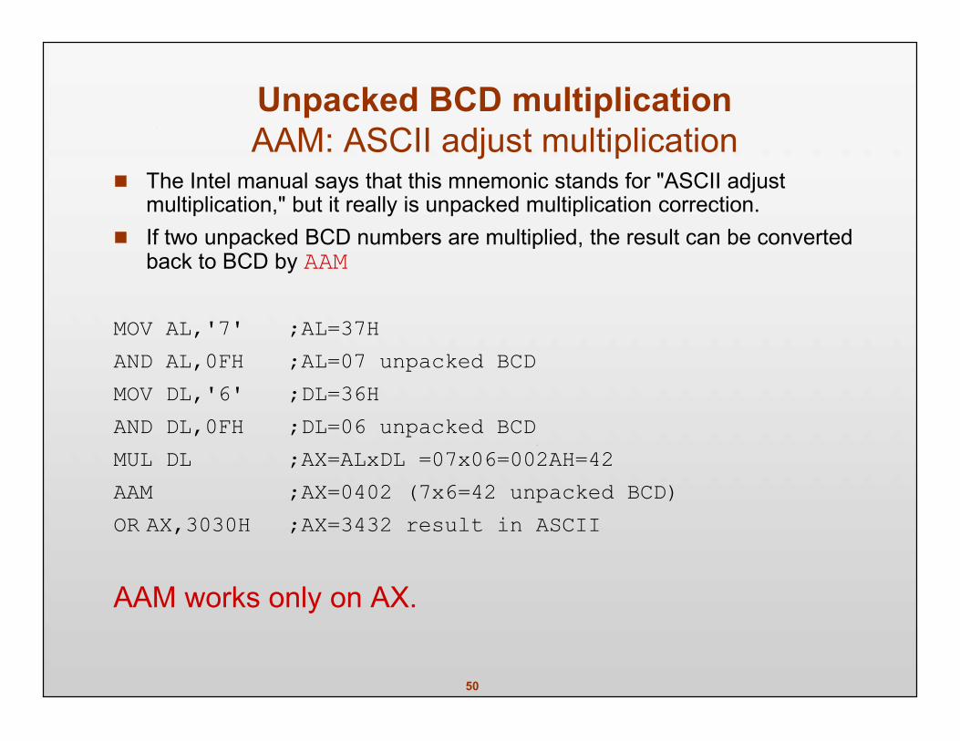
The Intel manual says that this mnemonic stands for "ASCII adjustmultiplication," but it really is unpacked multiplication correction.
If two unpacked BCD numbers are multiplied, the result can be convertedback to BCD by AAM
MOV AL,'7' ;AL=37HAND AL,0FH ;AL=07 unpacked BCDMOV DL,'6' ;DL=36HAND DL,0FH ;DL=06 unpacked BCDMUL DL ;AX=ALxDL =07x06=002AH=42AAM ;AX=0402 (7x6=42 unpacked BCD)OR AX,3030H ;AX=3432 result in ASCII
AAM works only on AX.
51
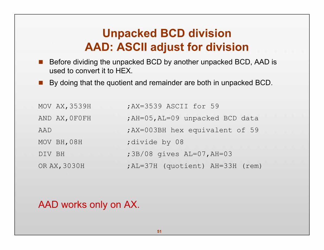
Unpacked BCD divisionAAD: ASCII adjust for division
Before dividing the unpacked BCD by another unpacked BCD, AAD isused to convert it to HEX.
By doing that the quotient and remainder are both in unpacked BCD.
MOV AX,3539H ;AX=3539 ASCII for 59AND AX,0F0FH ;AH=05,AL=09 unpacked BCD dataAAD ;AX=003BH hex equivalent of 59MOV BH,08H ;divide by 08DIV BH ;3B/08 gives AL=07,AH=03OR AX,3030H ;AL=37H (quotient) AH=33H (rem)
AAD works only on AX.
52
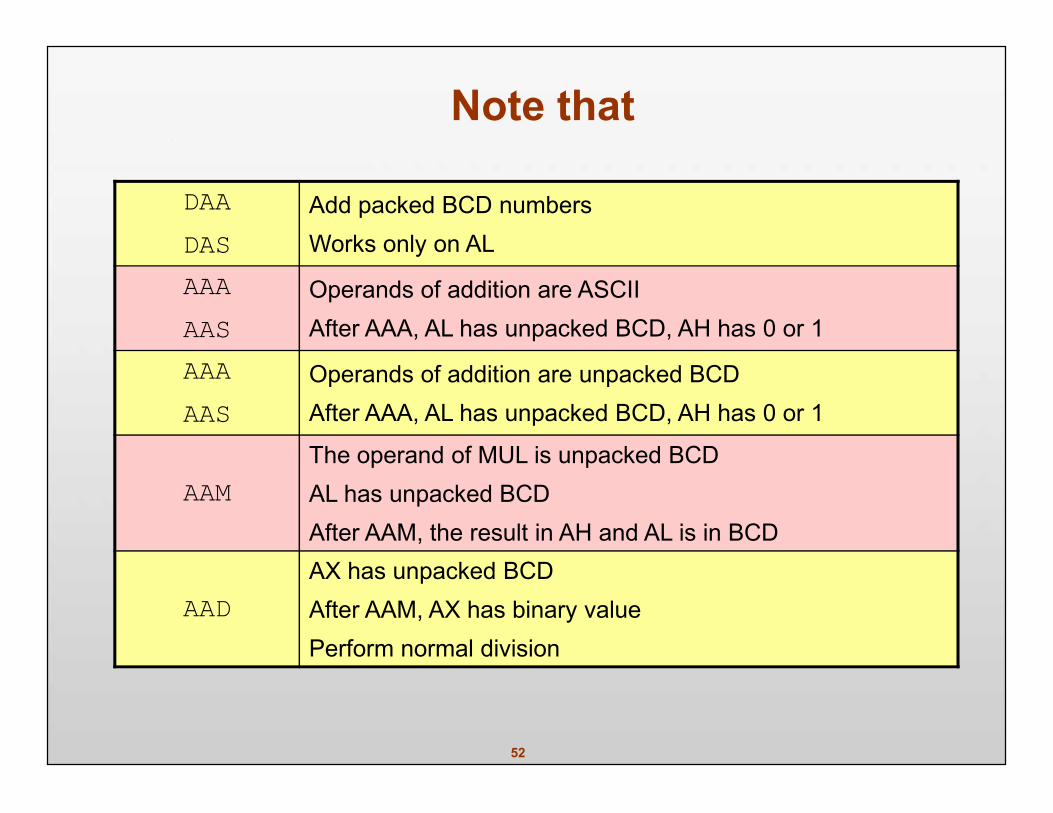
Note that
DAADAS
Add packed BCD numbersWorks only on AL
AAAAAS
Operands of addition are ASCIIAfter AAA, AL has unpacked BCD, AH has 0 or 1
AAAAAS
Operands of addition are unpacked BCDAfter AAA, AL has unpacked BCD, AH has 0 or 1
AAMThe operand of MUL is unpacked BCDAL has unpacked BCDAfter AAM, the result in AH and AL is in BCD
AADAX has unpacked BCDAfter AAM, AX has binary valuePerform normal division
53
Control TransferInstructions
54
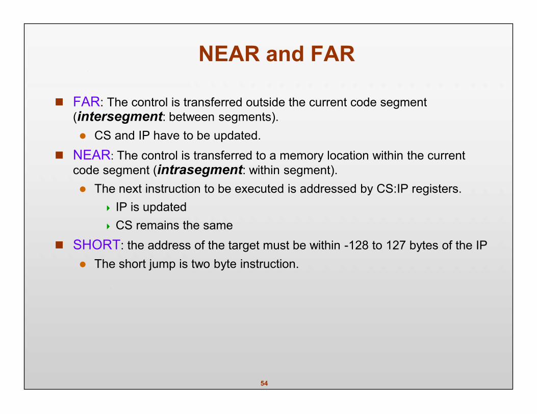
NEAR and FAR
FAR: The control is transferred outside the current code segment(intersegment: between segments). CS and IP have to be updated.
NEAR: The control is transferred to a memory location within the currentcode segment (intrasegment: within segment). The next instruction to be executed is addressed by CS:IP registers.
IP is updated CS remains the same
SHORT: the address of the target must be within -128 to 127 bytes of the IP The short jump is two byte instruction.
55
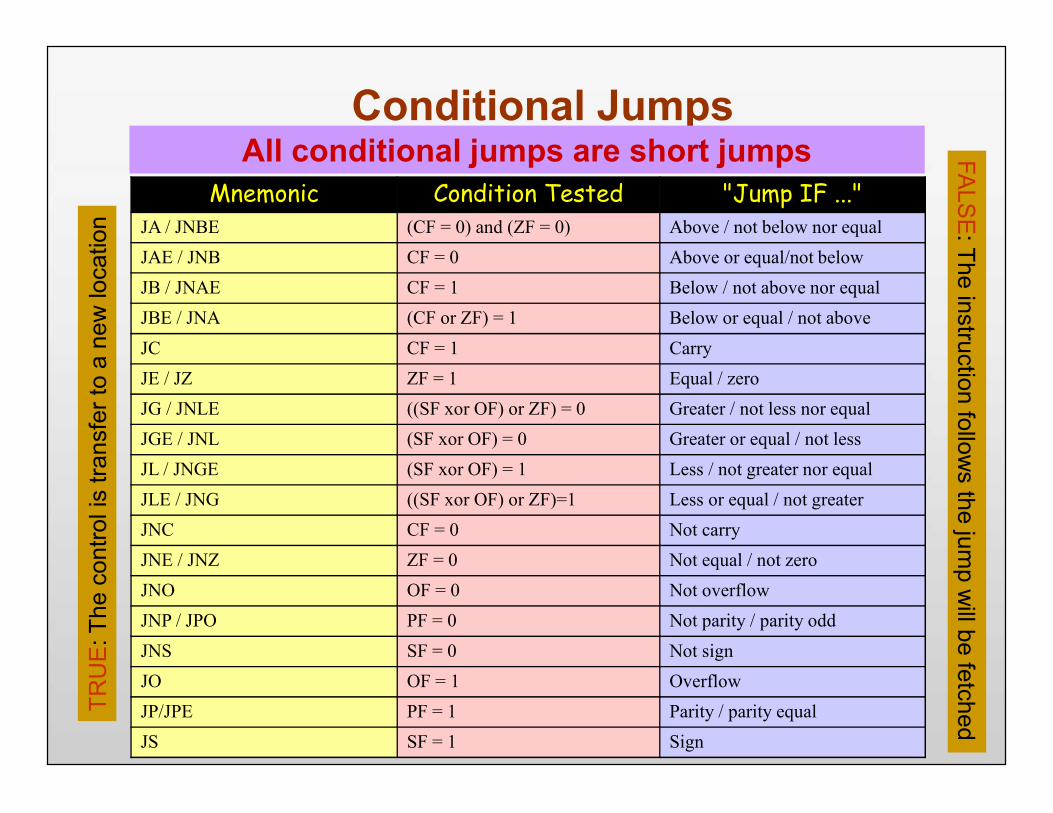
Mnemonic Condition Tested "Jump IF ..."JA / JNBE (CF = 0) and (ZF = 0) Above / not below nor equalJAE / JNB CF = 0 Above or equal/not belowJB / JNAE CF = 1 Below / not above nor equalJBE / JNA (CF or ZF) = 1 Below or equal / not aboveJC CF = 1 CarryJE / JZ ZF = 1 Equal / zeroJG / JNLE ((SF xor OF) or ZF) = 0 Greater / not less nor equalJGE / JNL (SF xor OF) = 0 Greater or equal / not lessJL / JNGE (SF xor OF) = 1 Less / not greater nor equalJLE / JNG ((SF xor OF) or ZF)=1 Less or equal / not greaterJNC CF = 0 Not carryJNE / JNZ ZF = 0 Not equal / not zeroJNO OF = 0 Not overflowJNP / JPO PF = 0 Not parity / parity oddJNS SF = 0 Not signJO OF = 1 OverflowJP/JPE PF = 1 Parity / parity equalJS SF = 1 Sign
Conditional JumpsTR
UE
: The
con
trol i
s tra
nsfe
r to
a ne
w lo
catio
nFA
LSE
: The instruction follows the jum
p will be fetched
All conditional jumps are short jumps
56
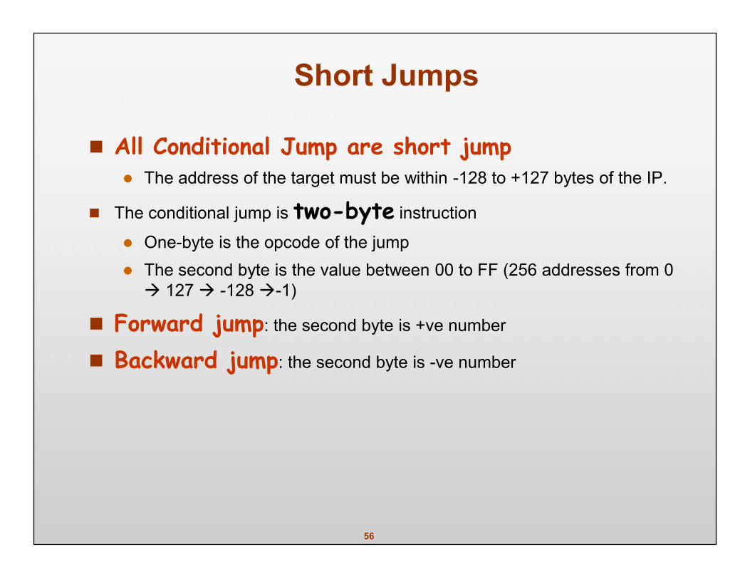
Short Jumps
All Conditional Jump are short jump The address of the target must be within -128 to +127 bytes of the IP.
The conditional jump is two-byte instruction
One-byte is the opcode of the jump The second byte is the value between 00 to FF (256 addresses from 0 127 -128-1)
Forward jump: the second byte is +ve number
Backward jump: the second byte is -ve number
57
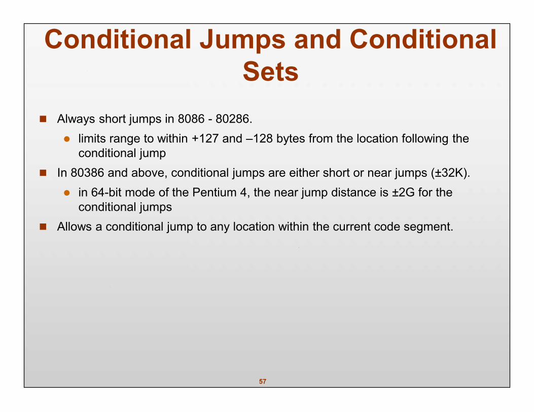
Conditional Jumps and ConditionalSets
Always short jumps in 8086 - 80286. limits range to within +127 and –128 bytes from the location following the
conditional jump In 80386 and above, conditional jumps are either short or near jumps (±32K).
in 64-bit mode of the Pentium 4, the near jump distance is ±2G for theconditional jumps
Allows a conditional jump to any location within the current code segment.
58
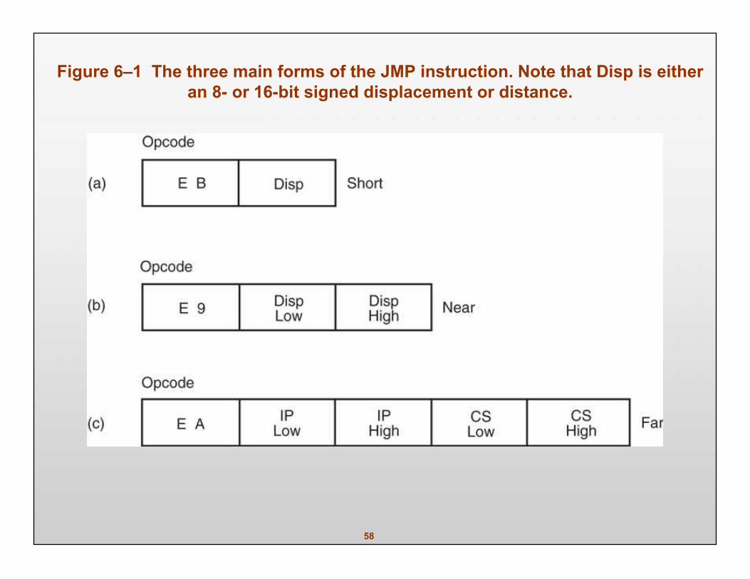
Figure 6–1 The three main forms of the JMP instruction. Note that Disp is eitheran 8- or 16-bit signed displacement or distance.
59
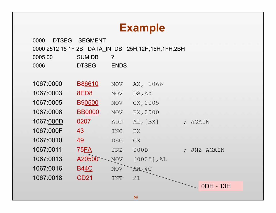
Example0000 DTSEG SEGMENT0000 2512 15 1F 2B DATA_IN DB 25H,12H,15H,1FH,2BH0005 00 SUM DB ?0006 DTSEG ENDS
1067:0000 B86610 MOV AX, 10661067:0003 8ED8 MOV DS,AX1067:0005 B90500 MOV CX,00051067:0008 BB0000 MOV BX,00001067:000D 0207 ADD AL,[BX] ; AGAIN1067:000F 43 INC BX1067:0010 49 DEC CX1067:0011 75FA JNZ 000D ; JNZ AGAIN1067:0013 A20500 MOV [0005],AL1067:0016 B44C MOV AH,4C1067:0018 CD21 INT 21
0DH - 13H
60
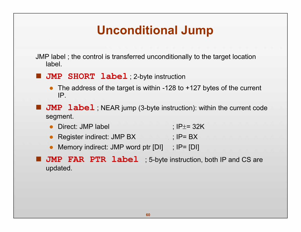
Unconditional Jump
JMP label ; the control is transferred unconditionally to the target locationlabel.
JMP SHORT label ; 2-byte instruction The address of the target is within -128 to +127 bytes of the current
IP.
JMP label ; NEAR jump (3-byte instruction): within the current codesegment. Direct: JMP label ; IP= 32K Register indirect: JMP BX ; IP= BX Memory indirect: JMP word ptr [DI] ; IP= [DI]
JMP FAR PTR label ; 5-byte instruction, both IP and CS areupdated.
61
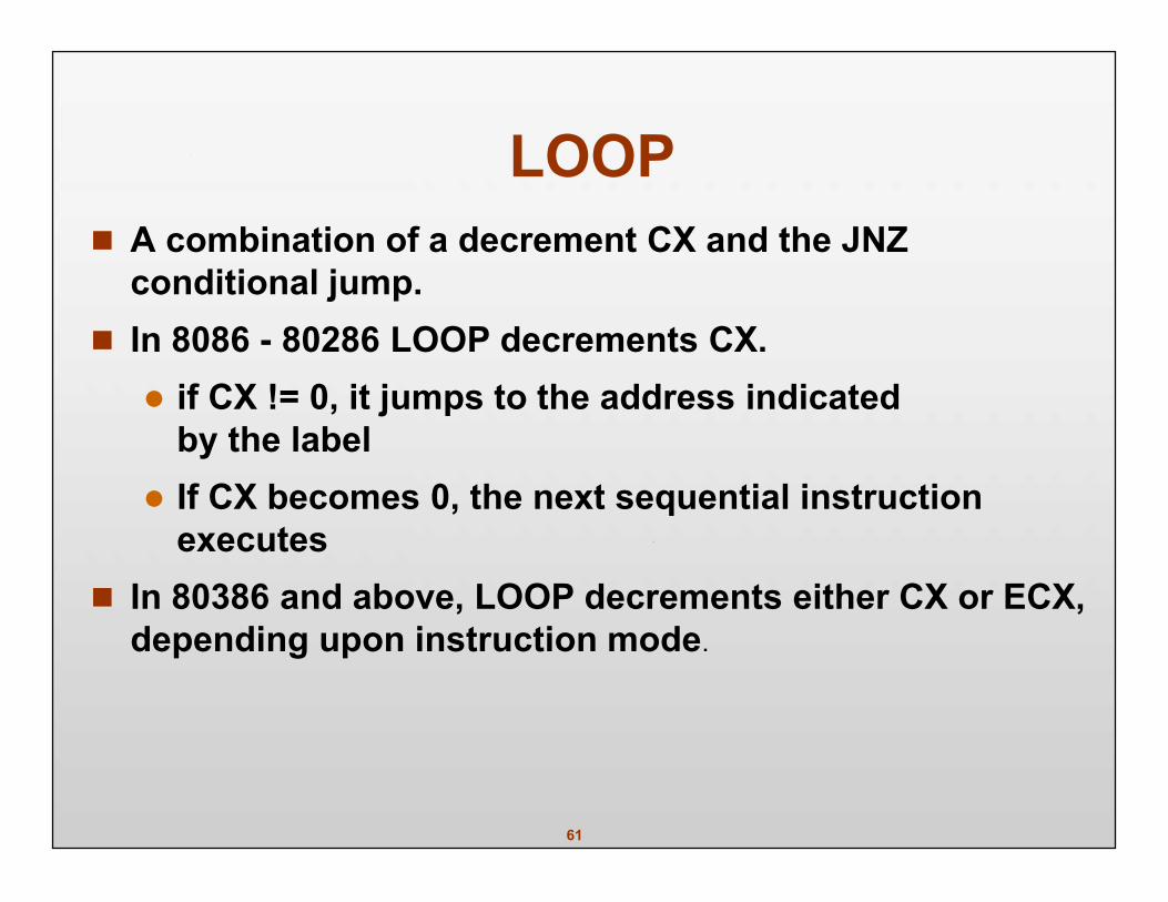
LOOP A combination of a decrement CX and the JNZ
conditional jump. In 8086 - 80286 LOOP decrements CX. if CX != 0, it jumps to the address indicated
by the label If CX becomes 0, the next sequential instruction
executes In 80386 and above, LOOP decrements either CX or ECX,
depending upon instruction mode.
62
In 16-bit instruction mode, LOOP uses CX; in the 32-bitmode, LOOP uses ECX. default is changed by the LOOPW (using CX) and
LOOPD (using ECX) instructions 80386 - Core2 In 64-bit mode, the loop counter is in RCX. and is 64 bits wide
There is no direct move from segment register tosegment register instruction.
63
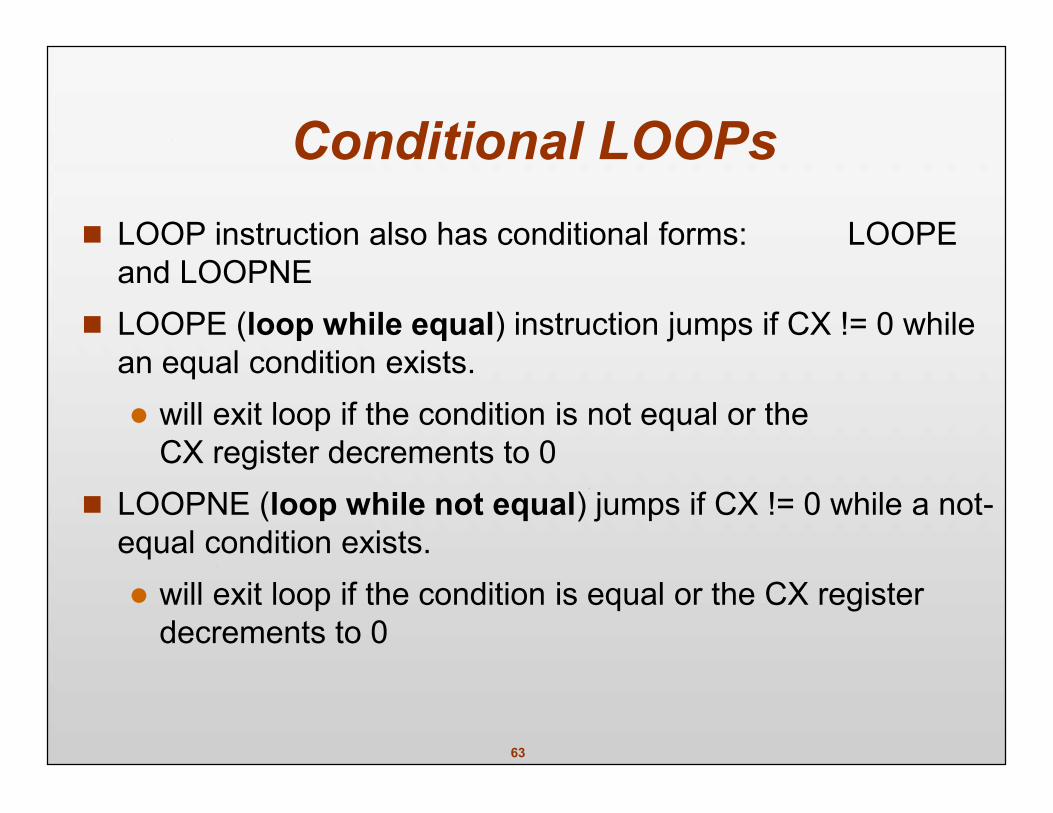
Conditional LOOPs LOOP instruction also has conditional forms: LOOPE
and LOOPNE LOOPE (loop while equal) instruction jumps if CX != 0 while
an equal condition exists. will exit loop if the condition is not equal or the
CX register decrements to 0 LOOPNE (loop while not equal) jumps if CX != 0 while a not-
equal condition exists. will exit loop if the condition is equal or the CX register
decrements to 0
64
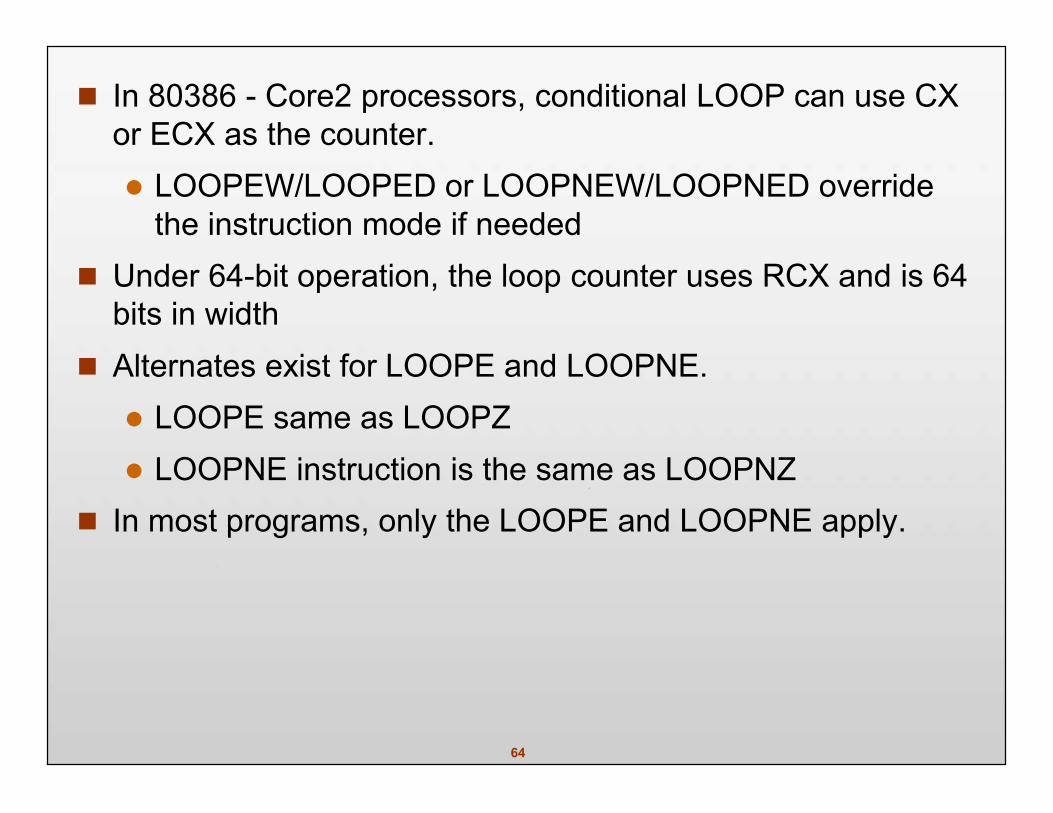
In 80386 - Core2 processors, conditional LOOP can use CXor ECX as the counter. LOOPEW/LOOPED or LOOPNEW/LOOPNED override
the instruction mode if needed Under 64-bit operation, the loop counter uses RCX and is 64
bits in width Alternates exist for LOOPE and LOOPNE. LOOPE same as LOOPZ LOOPNE instruction is the same as LOOPNZ
In most programs, only the LOOPE and LOOPNE apply.
65
Call Statements
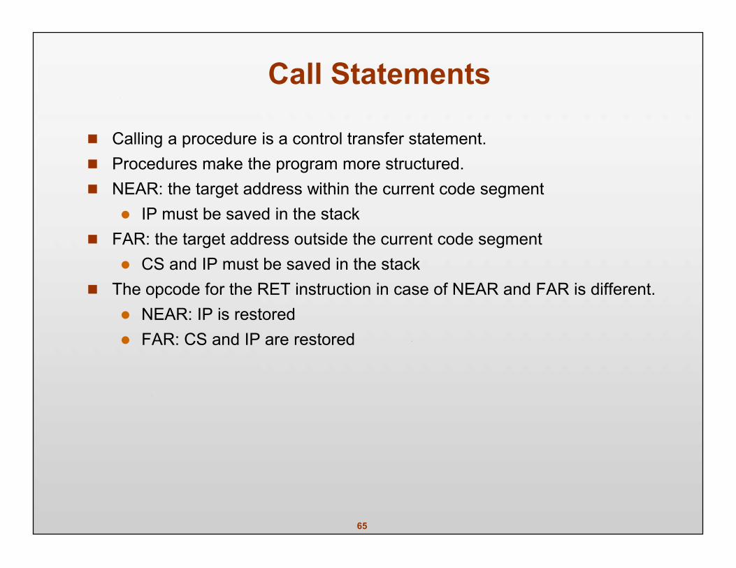
Calling a procedure is a control transfer statement. Procedures make the program more structured. NEAR: the target address within the current code segment
IP must be saved in the stack FAR: the target address outside the current code segment
CS and IP must be saved in the stack The opcode for the RET instruction in case of NEAR and FAR is different.
NEAR: IP is restored FAR: CS and IP are restored
66
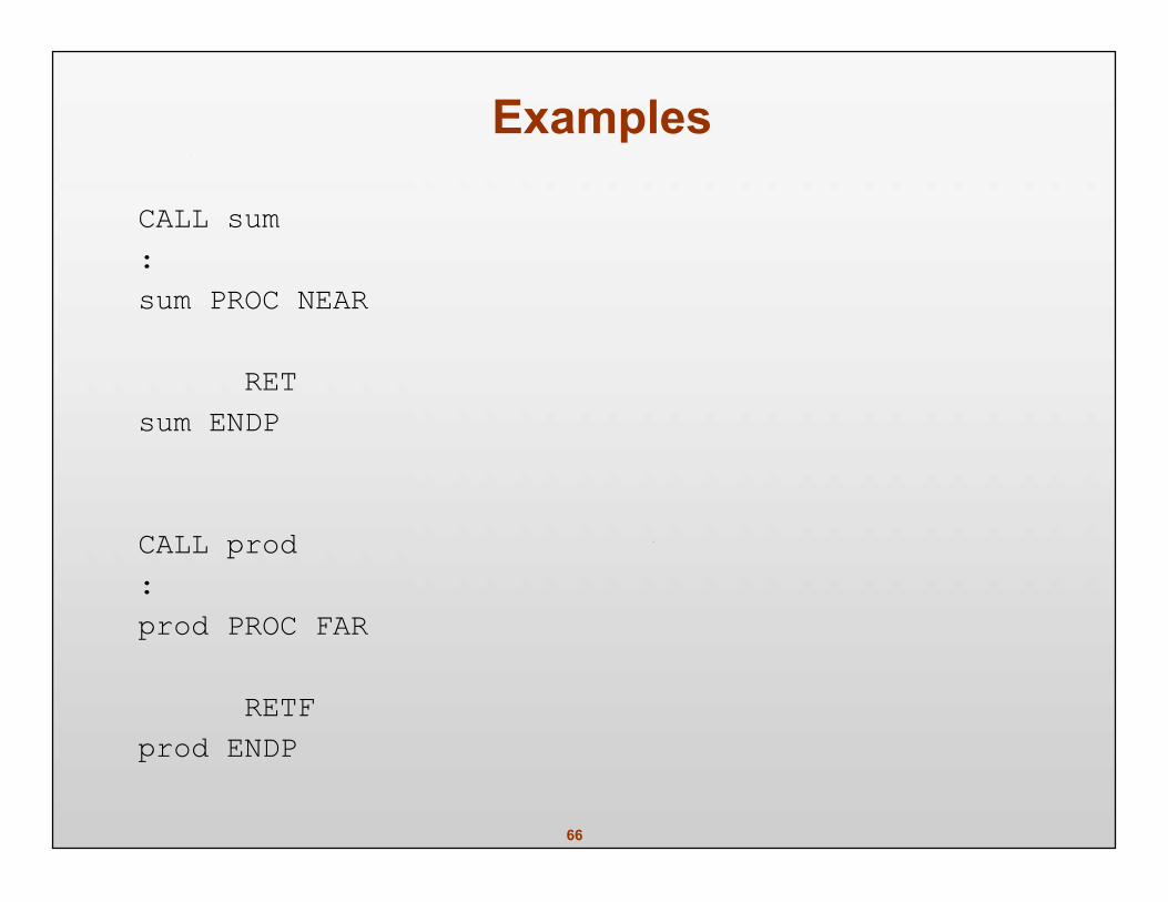
Examples
CALL sum:sum PROC NEAR
RETsum ENDP
CALL prod:prod PROC FAR
RETFprod ENDP
67
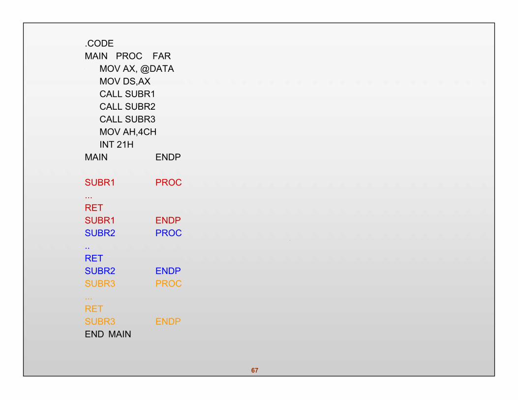
.CODEMAIN PROC FAR
MOV AX, @DATAMOV DS,AXCALL SUBR1CALL SUBR2CALL SUBR3MOV AH,4CHINT 21H
MAIN ENDP
SUBR1 PROC...RETSUBR1 ENDPSUBR2 PROC..RETSUBR2 ENDPSUBR3 PROC...RETSUBR3 ENDPEND MAIN
68
INTRO TO INTERRUPTS An interrupt is a hardware-generated CALL
externally derived from a hardware signal Or a software-generated CALL
internally derived from the execution of an instruction or by some other internalevent
at times an internal interrupt is called an exception Either type interrupts the program by calling
an interrupt service procedure (ISP) or interrupt handler.
69
Interrupt Vectors A 4-byte number stored in the first 1024 bytes of memory (00000H–003FFH) in
real mode. in protected mode, the vector table is replaced by an interrupt descriptor table
that uses 8-byte descriptors to describe each of the interrupts 256 different interrupt vectors.
each vector contains the address of an interrupt service procedure
70
Each vector contains a value for IP and CS that forms the address of the interruptservice procedure. the first 2 bytes contain IP; the last 2 bytes CS
Intel reserves the first 32 interrupt vectors for the present and future products. interrupt vectors (32–255) are available to users
Some reserved vectors are for errors that occur during the execution of software such as the divide error interrupt
71
Some vectors are reserved for the coprocessor. others occur for normal events in the system
In a personal computer, reserved vectors are used for system functions Vectors 1–6, 7, 9, 16, and 17 function in the real mode and protected mode.
the remaining vectors function only in the protected mode
72
Interrupt Instructions Three different interrupt instructions available:
INT, INTO, and INT 3 In real mode, each fetches a vector from the vector table, and then calls the
procedure stored at the location addressed by the vector. In protected mode, each fetches an interrupt descriptor from the interrupt
descriptor table. Similar to a far CALL instruction because it places the return address (IP/EIP and
CS)on the stack.
73
INTs 256 different software interrupt instructions (INTs) available to the programmer.
each INT instruction has a numeric operand whose range is 0 to 255 (00H–FFH)
For example, INT 100 uses interrupt vector 100, which appears at memoryaddress 190H–193H. address of the interrupt vector is determined by multiplying the interrupt type
number by 4
74
Address of the interrupt vector is determined by multiplying the interrupt typenumber by 4. INT 10H instruction calls the interrupt service procedure whose address is
stored beginning at memory location 40H (10H 4) in the mode In protected mode, the interrupt descriptor is located by multiplying the type
number by 8 because each descriptor is 8 bytes long
Each INT instruction is 2 bytes long. the first byte contains the opcode the second byte contains the vector type number
75
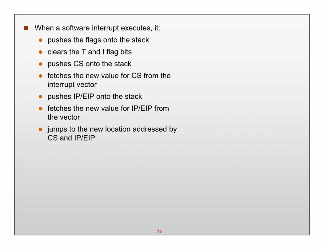
When a software interrupt executes, it: pushes the flags onto the stack clears the T and I flag bits pushes CS onto the stack fetches the new value for CS from the
interrupt vector pushes IP/EIP onto the stack fetches the new value for IP/EIP from
the vector jumps to the new location addressed by
CS and IP/EIP
76
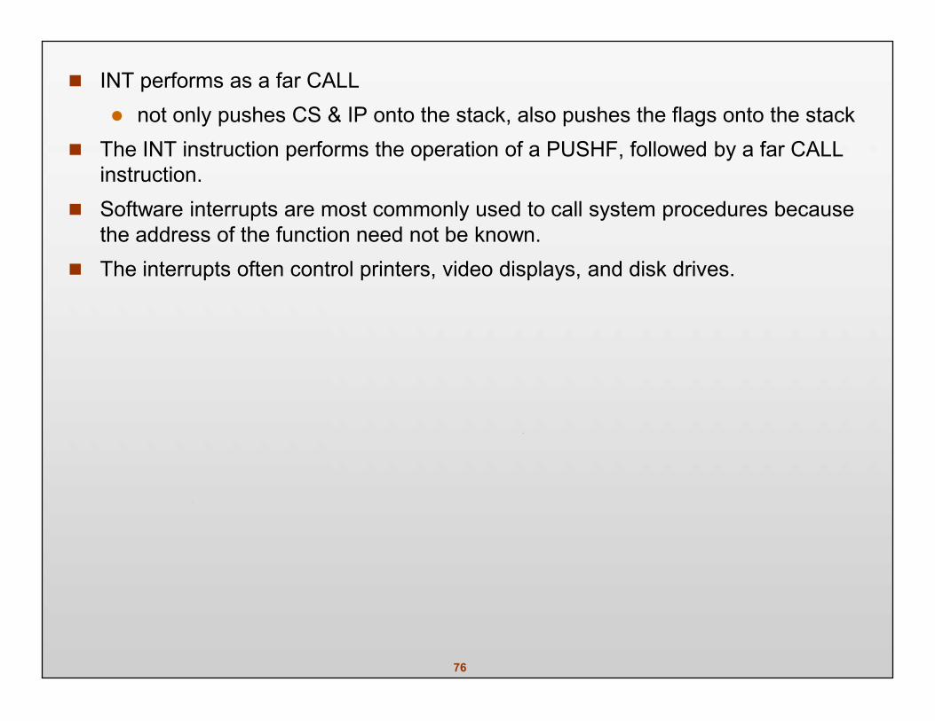
INT performs as a far CALL not only pushes CS & IP onto the stack, also pushes the flags onto the stack
The INT instruction performs the operation of a PUSHF, followed by a far CALLinstruction.
Software interrupts are most commonly used to call system procedures becausethe address of the function need not be known.
The interrupts often control printers, video displays, and disk drives.
77
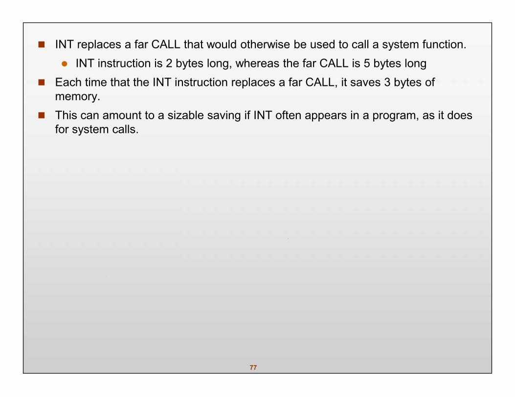
INT replaces a far CALL that would otherwise be used to call a system function. INT instruction is 2 bytes long, whereas the far CALL is 5 bytes long
Each time that the INT instruction replaces a far CALL, it saves 3 bytes ofmemory.
This can amount to a sizable saving if INT often appears in a program, as it doesfor system calls.
78
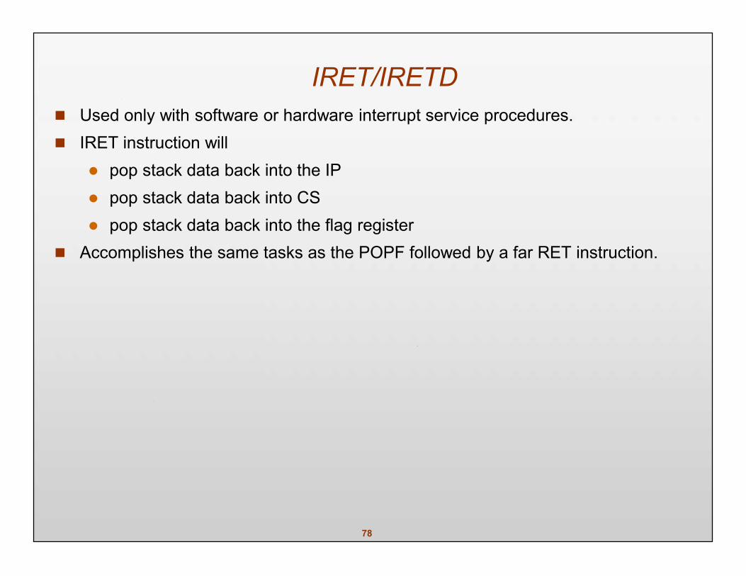
IRET/IRETD Used only with software or hardware interrupt service procedures. IRET instruction will
pop stack data back into the IP pop stack data back into CS pop stack data back into the flag register
Accomplishes the same tasks as the POPF followed by a far RET instruction.
79
When IRET executes, it restores the contents of I and T from the stack. preserves the state of these flag bits
If interrupts were enabled before an interrupt service procedure, they areautomatically re-enabled by the IRET instruction. because it restores the flag register
IRET is used in real mode and IRETD in the protected mode.
80
INT 3 A special software interrupt designed to function as a breakpoint.
a 1-byte instruction, while others are 2-byte Common to insert an INT 3 in software to interrupt or break the flow of the
software. function is called a breakpoint breakpoints help to debug faulty software
A breakpoint occurs for any software interrupt, but because INT 3 is 1 byte long, itis easier to use for this function.
81
INTO Interrupt on overflow (INTO) is a conditional software interrupt that tests overflow
flag (O). If O = 0, INTO performs no operation if O = 1 and an INTO executes, an interrupt
occurs via vector type number 4 The INTO instruction appears in software that adds or subtracts signed binary
numbers. eith these operations, it is possible to have an overflow
JO or INTO instructions detect the overflow.
82
An Interrupt Service Procedure Interrupts are usually reserved for system events. Suppose a procedure is required to add the contents of DI, SI, BP, and BX and
save the sum in AX. as a common task, it may be worthwhile to develop the task as a software
interrupt It is also important to save all registers are changed by the procedure using USES.
83
Interrupt Control Two instructions control the INTR pin. The set interrupt flag instruction (STI) places 1 in the I flag bit.
which enables the INTR pin The clear interrupt flag instruction (CLI) places a 0 into the I flag bit.
which disables the INTR pin The STI instruction enables INTR and the CLI instruction disables INTR.