Embed Size (px)
Citation preview
ARM ArchitectureReference Manual
Thumb-2 Supplement
Copyright © 2004, 2005 ARM Limited. All rights reserved.ARM DDI 0308D

ARM Architecture Reference Manual
Copyright © 2004, 2005 ARM Limited. All rights reserved.
Release Information
The following changes have been made to this document.
Proprietary Notice
ARM, the ARM Powered logo, Thumb, and StrongARM are registered trademarks of ARM Limited.
The ARM logo, AMBA, Angel, ARMulator, EmbeddedICE, ModelGen, Multi-ICE, PrimeCell, ARM7TDMI, ARM7TDMI-S, ARM9TDMI, ARM9E-S, ETM7, ETM9, TDMI, STRONG, are trademarks of ARM Limited.
All other products or services mentioned herein may be trademarks of their respective owners.
The product described in this document is subject to continuous developments and improvements. All particulars of the product and its use contained in this document are given by ARM in good faith.
1. Subject to the provisions set out below, ARM hereby grants to you a perpetual, non-exclusive, nontransferable, royalty free, worldwide licence to use this ARM Architecture Reference Manual for the purposes of developing; (i) software applications or operating systems which are targeted to run on microprocessor cores distributed under licence from ARM; (ii) tools which are designed to develop software programs which are targeted to run on microprocessor cores distributed under licence from ARM; (iii) integrated circuits which incorporate a microprocessor core manufactured under licence from ARM.
2. Except as expressly licensed in Clause 1 you acquire no right, title or interest in the ARM Architecture Reference Manual, or any Intellectual Property therein. In no event shall the licences granted in Clause 1, be construed as granting you expressly or by implication, estoppel or otherwise, licences to any ARM technology other than the ARM Architecture Reference Manual. The licence grant in Clause 1 expressly excludes any rights for you to use or take into use any ARM patents. No right is granted to you under the provisions of Clause 1 to; (i) use the ARM Architecture Reference Manual for the purposes of developing or having developed microprocessor cores or models thereof which are compatible in whole or part with either or both the instructions or programmer's models described in this ARM Architecture Reference Manual; or (ii) develop or have developed models of any microprocessor cores designed by or for ARM; or (iii) distribute in whole or in part this ARM Architecture Reference Manual to third parties without the express written permission of ARM; or (iv) translate or have translated this ARM Architecture Reference Manual into any other languages.
3.THE ARM ARCHITECTURE REFERENCE MANUAL IS PROVIDED "AS IS" WITH NO WARRANTIES EXPRESS, IMPLIED OR STATUTORY, INCLUDING BUT NOT LIMITED TO ANY WARRANTY OF SATISFACTORY QUALITY, NONINFRINGEMENT OR FITNESS FOR A PARTICULAR PURPOSE.
Change History
Date Issue Change
December 2004 A First release
April 2005 C Updated to incorporate corrections to errata
December 2005 D Updated for unified assembler syntax.
ii Copyright © 2004, 2005 ARM Limited. All rights reserved. ARM DDI 0308D
4. No licence, express, implied or otherwise, is granted to LICENSEE, under the provisions of Clause 1, to use the ARM tradename, in connection with the use of the ARM Architecture Reference Manual or any products based thereon. Nothing in Clause 1 shall be construed as authority for you to make any representations on behalf of ARM in respect of the ARM Architecture Reference Manual or any products based thereon.
Copyright © 2004, 2005 ARM limited
110 Fulbourn Road Cambridge, England CB1 9NJ
Restricted Rights Legend: Use, duplication or disclosure by the United States Government is subject to the restrictions set forth in DFARS 252.227-7013 (c)(1)(ii) and FAR 52.227-19
The right to use and copy this document is subject to the licence set out above.
ARM DDI 0308D Copyright © 2004, 2005 ARM Limited. All rights reserved. iii

iv Copyright © 2004, 2005 ARM Limited. All rights reserved. ARM DDI 0308D
ContentsARM Architecture Reference Manual Thumb-2 Supplement
PrefaceAbout this manual ............................................................................... viiiUnified Assembler Language ................................................................ ixUsing this manual .................................................................................. xConventions .......................................................................................... xiFurther reading .................................................................................... xiiFeedback ............................................................................................ xiii
Chapter 1 Introduction to Thumb-21.1 About Thumb-2 .................................................................................. 1-21.2 Changes to Thumb assembly language syntax ................................. 1-31.3 New 32-bit Thumb instructions ........................................................... 1-41.4 New 16-bit Thumb instructions ........................................................... 1-51.5 New 32-bit ARM instructions .............................................................. 1-61.6 Hint instructions ................................................................................. 1-71.7 Thumb-2 architecture constraints ....................................................... 1-9
Chapter 2 Programmers’ Model2.1 New program status register fields ..................................................... 2-22.2 Changes to exception handling .......................................................... 2-4
ARM DDI 0308D Copyright © 2004, 2005 ARM Limited. All rights reserved. v

Contents
2.3 Non-maskable fast interrupt support .................................................. 2-72.4 Exception and reset handling in Thumb state ................................... 2-92.5 Unaligned access support ................................................................ 2-102.6 Endian support ................................................................................. 2-132.7 Memory stores and exclusive access .............................................. 2-142.8 Hardware divide support .................................................................. 2-15
Chapter 3 The Thumb Instruction Set3.1 Instruction set encoding ..................................................................... 3-23.2 Instruction encoding for 16-bit Thumb instructions ............................ 3-33.3 Instruction encoding for 32-bit Thumb instructions .......................... 3-123.4 Conditional execution ....................................................................... 3-343.5 UNDEFINED and UNPREDICTABLE instruction set space ............ 3-363.6 Usage of 0b1111 as a register specifier in 32-bit encodings ........... 3-383.7 Usage of 0b1101 as a register specifier .......................................... 3-413.8 Thumb-2 and VFP support ............................................................... 3-43
Chapter 4 Thumb Instructions4.1 Format of instruction descriptions ...................................................... 4-24.2 Immediate constants .......................................................................... 4-84.3 Constant shifts applied to a register ................................................. 4-104.4 Memory accesses ............................................................................ 4-134.5 Memory hints ................................................................................... 4-144.6 Alphabetical list of Thumb instructions ............................................. 4-15
Chapter 5 New ARM instructions5.1 Alphabetical list of new ARM instructions .......................................... 5-2
Appendix A Pseudo-code definitionA.1 Instruction encoding diagrams and pseudo-code .............................. A-2A.2 Data Types ......................................................................................... A-4A.3 Expressions ....................................................................................... A-8A.4 Operators and built-in functions ....................................................... A-10A.5 Statements and program structure .................................................. A-18A.6 Helper procedures and functions ..................................................... A-22
Glossary
vi Copyright © 2004, 2005 ARM Limited. All rights reserved. ARM DDI 0308D

Preface
This preface describes the contents of this manual, then lists the conventions and terminology it uses.
• About this manual on page viii
• Unified Assembler Language on page ix
• Using this manual on page x
• Conventions on page xi
• Further reading on page xii
• Feedback on page xiii.
ARM DDI 0308D Copyright © 2004, 2005 ARM Limited. All rights reserved. vii
Preface
About this manual
The purpose of this manual is to describe Thumb®-2, its Instruction Set Architecture (ISA), and the changes to the programmers’ model it introduces. This manual also describes the extensions to the ARM® ISA introduced at the same time. Thumb-2 is a superset of the ARMv6 Thumb ISA described in the ARM Architecture Reference Manual (ARM DDI 0100).
Thumb-2 extends the Thumb architecture by adding the following:
• A substantial number of new 32-bit Thumb instructions. These cover most of the functionality of the ARM instruction set. The main omission is the absence of a condition field in almost all Thumb instructions.
• Several new 16-bit Thumb instructions. One of these, the IT (If Then) instruction, provides an efficient alternative mechanism for conditional execution.
Thumb-2 also extends the ARM ISA by adding a small number of new ARM instructions, and some additional variants of the ARM LDR and STR instructions. The additions provide ARM equivalents of instructions supported in the Thumb instruction set.
The precise effects of each new instruction are described, including any restrictions on its use. This information is of primary importance to authors of compilers, assemblers, and other programs that generate Thumb and ARM machine code.
Assembler syntax is given for the instructions described in this manual, allowing instructions to be specified in textual form. This is of considerable use to assembly code writers, and also when debugging either assembler or high-level language code at the single instruction level.
However, this manual is not intended as tutorial material for ARM assembler language, nor does it describe ARM assembler language at anything other than a very basic level. To make effective use of ARM assembler language, consult the documentation supplied with the assembler being used. Different assemblers vary considerably with respect to many aspects of assembler language, such as which assembler directives are accepted and how they are coded.
viii Copyright © 2004, 2005 ARM Limited. All rights reserved. ARM DDI 0308D
Preface
Unified Assembler Language
This version of the Thumb-2 supplement uses the new Unified Assembler Language (UAL). The new assembly language syntax provides a canonical form for all ARM and Thumb instructions. This replaces the earlier Thumb assembler language. For this reason, every Thumb instruction is included in this document.
The syntax of Thumb instructions is now the same as the syntax of ARM instructions. This requires some changes to the old Thumb syntax. See Changes to Thumb assembly language syntax on page 1-3 for details.
UAL describes the syntax for the mnemonic and the operands of each instruction. In addition, it assumes that instructions and data items can be given labels. It does not specify the syntax to be used for labels, nor what assembler directives and options are available. See your assembler documentation for these details.
UAL includes instruction selection rules that specify which instruction encoding is selected when more than one can provide the required functionality. For example, both 16-bit and 32-bit encodings exist for an ADD R0,R1,R2 instruction.
The most common instruction selection rule is that when both a 16-bit encoding and a 32-bit encoding are available, the 16-bit encoding is selected, to optimize code density.
Syntax options exist to override the normal instruction selection rules and ensure that a particular encoding is selected. These are useful when disassembling code, to ensure that subsequent assembly produces the original code, and in some other situations.
ARM DDI 0308D Copyright © 2004, 2005 ARM Limited. All rights reserved. ix
Preface
Using this manual
The information in this manual is organized into five chapters, as described below.
Chapter 1 Introduction to Thumb-2
Gives a brief overview of the Thumb-2 extension to the ARM and Thumb instruction sets.
Chapter 2 Programmers’ Model
Describes the changes to the Programmers’ Model introduced with Thumb-2.
Chapter 3 The Thumb Instruction Set
Gives a description of the Thumb-2 extension to the ARM and Thumb instruction sets, organized by type of instruction.
Chapter 4 Thumb Instructions
Contains detailed reference material on each Thumb instruction, arranged alphabetically by instruction mnemonic.
Chapter 5 New ARM instructions
Contains detailed reference material on each new ARM instruction, arranged alphabetically by instruction mnemonic.
x Copyright © 2004, 2005 ARM Limited. All rights reserved. ARM DDI 0308D
Preface
Conventions
This manual employs typographic and other conventions intended to improve its ease of use.
General typographic conventions
typewriter Is used for assembler syntax descriptions, pseudo-code descriptions of instructions, and source code examples. For more details of the conventions used in assembler syntax descriptions see Assembler syntax on page 4-4. For more details of pseudo-code conventions see Appendix A Pseudo-code definition.
The typewriter font is also used in the main text for instruction mnemonics and for references to other items appearing in assembler syntax descriptions, pseudo-code descriptions of instructions and source code examples.
italic Highlights important notes, introduces special terminology, and denotes internal cross-references and citations.
bold Is used for emphasis in descriptive lists and elsewhere, where appropriate.
SMALL CAPITALS Are used for a few terms which have specific technical meanings. Their meanings can be found in the Glossary.
ARM DDI 0308D Copyright © 2004, 2005 ARM Limited. All rights reserved. xi
Preface
Further reading
This section lists publications that provide additional information on the ARM family of processors.
ARM periodically provides updates and corrections to its documentation. See http://www.arm.com for current errata sheets and addenda, and the ARM Frequently Asked Questions.
ARM publications
This book is a supplement to, and must be read in conjunction with, the ARM Architecture Reference Manual (ARM DDI 0100), version F or later. This book also contains references to the ARM Architecture Reference Manual, Security Extensions supplement (ARM DDI 0309).
xii Copyright © 2004, 2005 ARM Limited. All rights reserved. ARM DDI 0308D
Preface
Feedback
ARM Limited welcomes feedback on its documentation.
Feedback on this book
If you notice any errors or omissions in this book, send email to errata@arm giving:
• the document title
• the document number
• the page number(s) to which your comments apply
• a concise explanation of the problem.
General suggestions for additions and improvements are also welcome.
ARM DDI 0308D Copyright © 2004, 2005 ARM Limited. All rights reserved. xiii

Preface
xiv Copyright © 2004, 2005 ARM Limited. All rights reserved. ARM DDI 0308D
Chapter 1 Introduction to Thumb-2
This chapter introduces Thumb®-2 and contains the following sections:
• About Thumb-2 on page 1-2
• Changes to Thumb assembly language syntax on page 1-3
• New 32-bit Thumb instructions on page 1-4
• New 16-bit Thumb instructions on page 1-5
• New 32-bit ARM instructions on page 1-6
• Hint instructions on page 1-7
• Thumb-2 architecture constraints on page 1-9.
ARM DDI 0308D Copyright © 2004, 2005 ARM Limited. All rights reserved. 1-1
Introduction to Thumb-2
1.1 About Thumb-2
Thumb-2 is a major enhancement to the Thumb Instruction Set Architecture (ISA). It introduces 32-bit instructions that can be intermixed freely with the older 16-bit Thumb instructions. These new 32-bit instructions cover almost all the functionality of the ARM® instruction set.
The most important difference between the Thumb ISA and the ARM ISA is that most 32-bit Thumb instructions are unconditional, whereas almost all ARM instructions can be conditional. However, Thumb-2 introduces a new If-Then (IT) instruction that delivers much of the functionality of the condition field in ARM instructions.
Thumb-2 delivers overall code density comparable with Thumb, together with the performance levels associated with the ARM ISA. Before Thumb-2, developers had to choose between Thumb for size, or ARM for performance.
In addition to the new 32-bit Thumb instructions, there are several new 16-bit Thumb instructions. Several new 32-bit ARM instructions are introduced at the same time.
1.1.1 Register 15
Most Thumb 32-bit instructions cannot use the PC as a source or destination register. Instead, if a register is specified as 0b1111 in an instruction encoding, the instruction is a special case instruction. If an instruction definition does not specify otherwise, the instruction is UNPREDICTABLE if a register is specified as 0b1111. See Usage of 0b1111 as a register specifier in 32-bit encodings on page 3-38 for more information.
1-2 Copyright © 2004, 2005 ARM Limited. All rights reserved. ARM DDI 0308D
Introduction to Thumb-2
1.2 Changes to Thumb assembly language syntax
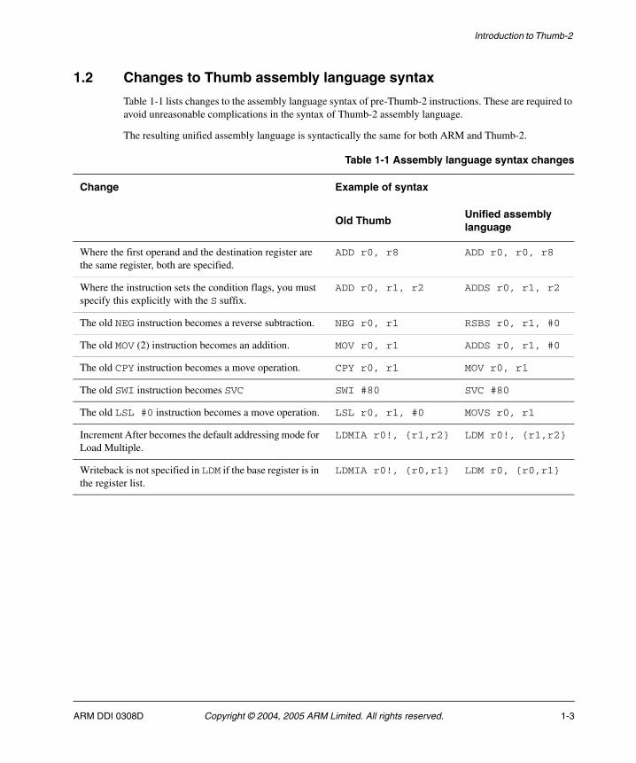
Table 1-1 lists changes to the assembly language syntax of pre-Thumb-2 instructions. These are required to avoid unreasonable complications in the syntax of Thumb-2 assembly language.
The resulting unified assembly language is syntactically the same for both ARM and Thumb-2.
Table 1-1 Assembly language syntax changes
Change Example of syntax
Old ThumbUnified assembly language
Where the first operand and the destination register are the same register, both are specified.
ADD r0, r8 ADD r0, r0, r8
Where the instruction sets the condition flags, you must specify this explicitly with the S suffix.
ADD r0, r1, r2 ADDS r0, r1, r2
The old NEG instruction becomes a reverse subtraction. NEG r0, r1 RSBS r0, r1, #0
The old MOV (2) instruction becomes an addition. MOV r0, r1 ADDS r0, r1, #0
The old CPY instruction becomes a move operation. CPY r0, r1 MOV r0, r1
The old SWI instruction becomes SVC SWI #80 SVC #80
The old LSL #0 instruction becomes a move operation. LSL r0, r1, #0 MOVS r0, r1
Increment After becomes the default addressing mode for Load Multiple.
LDMIA r0!, {r1,r2} LDM r0!, {r1,r2}
Writeback is not specified in LDM if the base register is in the register list.
LDMIA r0!, {r0,r1} LDM r0, {r0,r1}
ARM DDI 0308D Copyright © 2004, 2005 ARM Limited. All rights reserved. 1-3
Introduction to Thumb-2
1.3 New 32-bit Thumb instructions
The new 32-bit Thumb instructions are designed for:
• the existing ARM/Thumb Programmers’ Model, with as few modifications as possible. Certain changes are essential to introduce the 32-bit Thumb instructions, notably to the Prefetch abort and Undefined Instruction exceptions. There is no increase in the number of general purpose or special purpose registers, and no increase in register sizes.
• existing compiler code generation techniques, as far as possible. New concepts are supplementary rather than obligatory. For example, literals can still be loaded using PC-relative instructions, or use in-line immediate values embedded in the MOV 16-bit immediate and MOVT instructions.
The new 32-bit Thumb instructions are added in the space previously occupied by the Thumb BL and BLX instructions. This is made possible by treating the BL and BLX instructions as 32-bit instructions, instead of treating them as two 16-bit instructions.
This means that BL and BLX, and all the other 32-bit Thumb instructions, can only take exceptions on their start address. They cannot take exceptions at the boundary between halfword1 and halfword2 of the instruction. All implementations must ensure that both halfwords are fetched and consolidated before they are issued and executed to comply with this exception event restriction. This is a change from Thumb. Before Thumb-2, the two halfwords of BL and BLX instructions execute independently, and can take exceptions independently.
1-4 Copyright © 2004, 2005 ARM Limited. All rights reserved. ARM DDI 0308D
Introduction to Thumb-2
1.4 New 16-bit Thumb instructions
There are seven new 16-bit Thumb instructions.
1.4.1 If-Then
IT allows one to four following Thumb instructions (the IT block) to be conditional. The conditions for the instructions in the IT block must either all be the same, or some of them can be the inverse condition of the others. See IT on page 4-92 for details.
1.4.2 Compare and branch on zero, or non-zero
CBZ and CBNZ improve code density by replacing a very common two instruction sequence with a single instruction.
In addition, they preserve the condition code flags. This means that a condition code flag setting generated before the instruction can be used after it. This is not possible with the two instruction sequence that CBZ and CBNZ replace.
See CBZ on page 4-60 and CBNZ on page 4-58 for details.
1.4.3 No operation
Use NOP for padding, for example to place the following instruction on a 64-bit boundary.
See NOP-compatible hints on page 1-8 and NOP on page 4-189 for details.
1.4.4 Send event
SEV (Send Event) is a hint instruction. See SEV on page 4-271 for details.
1.4.5 Wait for event
WFE (Wait For Event) is a hint instruction. See WFE on page 4-467 for details.
1.4.6 Wait for interrupt
WFI (Wait For Interrupt) is a hint instruction. See WFI on page 4-469 for details.
1.4.7 Yield
YIELD is a hint instruction. See YIELD on page 4-471 for details.
ARM DDI 0308D Copyright © 2004, 2005 ARM Limited. All rights reserved. 1-5
Introduction to Thumb-2
1.5 New 32-bit ARM instructions
Some new functionality introduced for Thumb-2 is also available in the ARM ISA. This is described in:
• New T variants of LDR and STR
• New variants of LDREX and STREX
• Miscellaneous instructions.
1.5.1 New T variants of LDR and STR
The ARM LDRH, LDRSB, LDRSH and STRH instructions now have T variants.
Note Like existing ARM T variants of LDR and STR, these instructions use a post-indexed addressing mode. This is different from Thumb variants of LDR and STR, which use pre-indexed addressing.
1.5.2 New variants of LDREX and STREX
The ARM LDREX and STREX instructions now have B, H, and D (Byte, Halfword, and Doubleword) variants. In addition, there is a CLREX instruction that clears the local record of a request for exclusive access without performing a store.
1.5.3 Miscellaneous instructions
The following instructions are introduced:
BFC Bitfield Clear.
BFI Bitfield Insert.
MLS Multiply and Subtract. Subtracts the product from the accumulator register.
MOV New Move Wide variant. Load a 16-bit immediate to bits[15:0] of a register.
MOVT Move Top. Load a 16-bit immediate to bits[31:16] of a register, leaving bits[15:0] unaltered.
RBIT Reverse bits in word.
SBFX Signed Bitfield extract.
UBFX Unsigned Bitfield extract.
For details, see Chapter 5 New ARM instructions.
1-6 Copyright © 2004, 2005 ARM Limited. All rights reserved. ARM DDI 0308D
Introduction to Thumb-2
1.6 Hint instructions
There are two classes of hint instruction in the ARM architecture:
• memory hints, that interact with the memory system
• NOP-compatible hints, that have no associated register dependencies.
These are described in:
• Memory hint instructions
• NOP-compatible hints on page 1-8.
1.6.1 Memory hint instructions
In addition to the PLD and PLI instructions, additional 32-bit Thumb instruction set space has been reserved for memory hint instructions.
32-bit Thumb-2 memory hints decode as hw1[12:4] = 0b1100Ax0B1 where:
AB = 0b00 is assigned to PLD
AB = 0b10 is assigned to PLI
AB = 0bx1 is reserved and must behave as a NOP instruction.
An implementation is not obliged to implement memory hint instructions. If they are not implemented, they must behave as a NOP instruction.
ARM DDI 0308D Copyright © 2004, 2005 ARM Limited. All rights reserved. 1-7
Introduction to Thumb-2
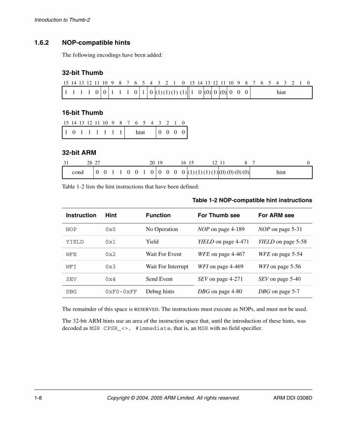
1.6.2 NOP-compatible hints
The following encodings have been added:
32-bit Thumb
16-bit Thumb
32-bit ARM
Table 1-2 lists the hint instructions that have been defined:
The remainder of this space is RESERVED. The instructions must execute as NOPs, and must not be used.
The 32-bit ARM hints use an area of the instruction space that, until the introduction of these hints, was decoded as MSR CPSR_<>, #immediate, that is, an MSR with no field specifier.
15 14 13 12 11 10 9 8 7 6 5 4 3 2 1 0 15 14 13 12 11 10 9 8 7 6 5 4 3 2 1 0
1 1 1 1 0 0 1 1 1 0 1 0 (1) (1) (1) (1) 1 0 (0) 0 (0) 0 0 0 hint
15 14 13 12 11 10 9 8 7 6 5 4 3 2 1 0
1 0 1 1 1 1 1 1 hint 0 0 0 0
31 28 27 20 19 16 15 12 11 8 7 0
cond 0 0 1 1 0 0 1 0 0 0 0 0 (1) (1) (1) (1) (0) (0) (0) (0) hint
Table 1-2 NOP-compatible hint instructions
Instruction Hint Function For Thumb see For ARM see
NOP 0x0 No Operation NOP on page 4-189 NOP on page 5-31
YIELD 0x1 Yield YIELD on page 4-471 YIELD on page 5-58
WFE 0x2 Wait For Event WFE on page 4-467 WFE on page 5-54
WFI 0x3 Wait For Interrupt WFI on page 4-469 WFI on page 5-56
SEV 0x4 Send Event SEV on page 4-271 SEV on page 5-40
DBG 0xF0-0xFF Debug hints DBG on page 4-80 DBG on page 5-7
1-8 Copyright © 2004, 2005 ARM Limited. All rights reserved. ARM DDI 0308D
Introduction to Thumb-2
1.7 Thumb-2 architecture constraints
Almost all the functionality of the ARM ISA is covered by the Thumb ISA. Apart from the absence of a condition field, the main exceptions are covered in:
• ARM instructions with no Thumb-2 equivalent
• New functionality introduced with Thumb-2
• 32-bit Thumb instructions with less functionality than ARM instructions on page 1-10.
1.7.1 ARM instructions with no Thumb-2 equivalent
The following ARM instructions have no Thumb-2 equivalents:
RSC Reverse Subtract with Carry.
SWP Swap. SWP is superseded by LDREX and STREX.
SWPB Swap bytes. SWPB is superseded by LDREXB and STREXB.
The use of SWP and SWPB is deprecated in ARMv6.
1.7.2 New functionality introduced with Thumb-2
Some new 32-bit instructions are introduced in both Thumb and ARM. These are described in New 32-bit Thumb instructions on page 1-4 and New 32-bit ARM instructions on page 1-6.
In addition, there are two new 32-bit Thumb instructions with restricted availability:
SDIV Signed Divide
UDIV Unsigned Divide.
These two instructions are only available in ARMv7-R implementations, and are not available in ARM state.
Note The ARM architecture defines architecture profiles, to target different market segments better. Two profiles are directly affected by this Thumb-2 supplement:
• ARMv7-A (the application profile) that supports the Virtual Memory System Architecture (VMSA)
• ARMv7-R (the real-time profile) that supports the Protected Memory System Architecture (PMSA).
These profiles share the existing ARM/Thumb Programmers’ Model including the register file, exception handling, and the CPSR/SPSR.
ARM DDI 0308D Copyright © 2004, 2005 ARM Limited. All rights reserved. 1-9
Introduction to Thumb-2
1.7.3 32-bit Thumb instructions with less functionality than ARM instructions
The following 32-bit Thumb instructions cannot update the condition code flags:
MLA Multiply Accumulate
MUL Multiply
SMLAL Signed Multiply Accumulate Long
SMULL Signed Multiply Long
UMLAL Unsigned Multiply Accumulate Long
UMULL Unsigned Multiply Long.
Data processing instructions cannot combine a register-controlled shift with other functions. Register-controlled shifts are only available as separate instructions. This affects the following instructions:
AND Logical AND
EOR Logical Exclusive OR
SUB Subtract
RSB Reverse Subtract
ADD Add
ADC Add with Carry
SBC Subtract with Carry
TST Test
TEQ Test Equivalence
CMP Compare
CMN Compare negated
ORR Logical (inclusive) OR
MOV Move
BIC Bit Clear
MVN Move Not.
The Move to Status Register instruction, MSR, cannot load an immediate value.
Load Multiple and Store Multiple have some restrictions on their functionality. For details, see:
• LDMDB / LDMEA on page 4-96
• LDMIA / LDMFD on page 4-98
• POP on page 4-209
• PUSH on page 4-211
• STMDB / STMFD on page 4-333
• STMIA / STMEA on page 4-335.
1-10 Copyright © 2004, 2005 ARM Limited. All rights reserved. ARM DDI 0308D
Chapter 2 Programmers’ Model
This chapter describes the changes to the programmers’ model introduced with Thumb®-2. It contains the following sections:
• New program status register fields on page 2-2
• Changes to exception handling on page 2-4
• Non-maskable fast interrupt support on page 2-7
• Exception and reset handling in Thumb state on page 2-9
• Unaligned access support on page 2-10
• Endian support on page 2-13
• Memory stores and exclusive access on page 2-14
• Hardware divide support on page 2-15.
ARM DDI 0308D Copyright © 2004, 2005 ARM Limited. All rights reserved. 2-1
Programmers’ Model
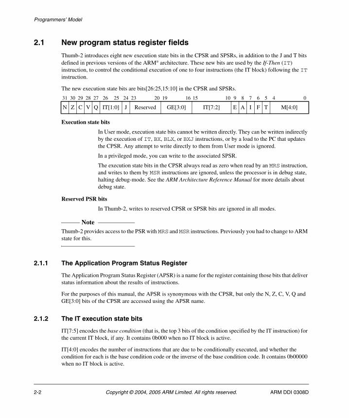
2.1 New program status register fields
Thumb-2 introduces eight new execution state bits in the CPSR and SPSRs, in addition to the J and T bits defined in previous versions of the ARM® architecture. These new bits are used by the If-Then (IT) instruction, to control the conditional execution of one to four instructions (the IT block) following the IT instruction.
The new execution state bits are bits[26:25,15:10] in the CPSR and SPSRs.
Execution state bits
In User mode, execution state bits cannot be written directly. They can be written indirectly by the execution of IT, BX, BLX, or BXJ instructions, or by a load to the PC that updates the CPSR. Any attempt to write directly to them from User mode is ignored.
In a privileged mode, you can write to the associated SPSR.
The execution state bits in the CPSR always read as zero when read by an MRS instruction, and writes to them by MSR instructions are ignored, unless the processor is in debug state, halting debug-mode. See the ARM Architecture Reference Manual for more details about debug state.
Reserved PSR bits
In Thumb-2, writes to reserved CPSR or SPSR bits are ignored in all modes.
Note Thumb-2 provides access to the PSR with MRS and MSR instructions. Previously you had to change to ARM state for this.
2.1.1 The Application Program Status Register
The Application Program Status Register (APSR) is a name for the register containing those bits that deliver status information about the results of instructions.
For the purposes of this manual, the APSR is synonymous with the CPSR, but only the N, Z, C, V, Q and GE[3:0] bits of the CPSR are accessed using the APSR name.
2.1.2 The IT execution state bits
IT[7:5] encodes the base condition (that is, the top 3 bits of the condition specified by the IT instruction) for the current IT block, if any. It contains 0b000 when no IT block is active.
IT[4:0] encodes the number of instructions that are due to be conditionally executed, and whether the condition for each is the base condition code or the inverse of the base condition code. It contains 0b00000 when no IT block is active.
31 30 29 28 27 26 25 24 23 20 19 16 15 10 9 8 7 6 5 4 0
N Z C V Q IT[1:0] J Reserved GE[3:0] IT[7:2] E A I F T M[4:0]
2-2 Copyright © 2004, 2005 ARM Limited. All rights reserved. ARM DDI 0308D
Programmers’ Model
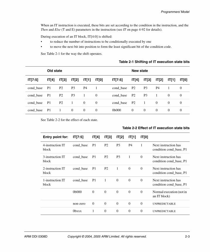
When an IT instruction is executed, these bits are set according to the condition in the instruction, and the Then and Else (T and E) parameters in the instruction (see IT on page 4-92 for details).
During execution of an IT block, IT[4:0] is shifted:
• to reduce the number of instructions to be conditionally executed by one
• to move the next bit into position to form the least significant bit of the condition code.
See Table 2-1 for the way the shift operates.
See Table 2-2 for the effect of each state.
Table 2-1 Shifting of IT execution state bits
Old state New state
IT[7:5] IT[4] IT[3] IT[2] IT[1] IT[0] IT[7:5] IT[4] IT[3] IT[2] IT[1] IT[0]
cond_base P1 P2 P3 P4 1 cond_base P2 P3 P4 1 0
cond_base P1 P2 P3 1 0 cond_base P2 P3 1 0 0
cond_base P1 P2 1 0 0 cond_base P2 1 0 0 0
cond_base P1 1 0 0 0 0b000 0 0 0 0 0
Table 2-2 Effect of IT execution state bits
Entry point for: IT[7:5] IT[4] IT[3] IT[2] IT[1] IT[0]
4-instruction IT block
cond_base P1 P2 P3 P4 1 Next instruction has condition cond_base, P1
3-instruction IT block
cond_base P1 P2 P3 1 0 Next instruction has condition cond_base, P1
2-instruction IT block
cond_base P1 P2 1 0 0 Next instruction has condition cond_base, P1
1-instruction IT block
cond_base P1 1 0 0 0 Next instruction has condition cond_base, P1
0b000 0 0 0 0 0 Normal execution (not in an IT block)
non-zero 0 0 0 0 0 UNPREDICTABLE
0bxxx 1 0 0 0 0 UNPREDICTABLE
ARM DDI 0308D Copyright © 2004, 2005 ARM Limited. All rights reserved. 2-3
Programmers’ Model
2.2 Changes to exception handling
Thumb-2 introduces some extra considerations in exception handling.
All Thumb-2 implementations must have:
• an IFAR
• a DFAR
• a memory read/write bit in the DFSRs.
For details, see the ARM Architecture Reference Manual.
This section describes the changes, in the following subsections:
• IRQ and FIQ
• Prefetch abort
• Data abort
• SVC on page 2-5
• Undefined instruction on page 2-5
• Exception link register on page 2-6.
2.2.1 IRQ and FIQ
Thumb-2 does not introduce any changes to the handling of IRQs or FIQs, except that exceptions cannot occur at the boundary between halfword1 and halfword2 of a 32-bit instruction. See New 32-bit Thumb instructions on page 1-4 for more information. No changes to code are required.
See also Non-maskable fast interrupt support on page 2-7.
2.2.2 Prefetch abort
Prefetch abort handlers must use the IFAR method to determine the aborting address.
This is because an instruction can span a page boundary. R14_abt indicates the address in the first page, but the abort might actually have occurred on the second page.
In Thumb-2, BL and BLX instructions are true 32-bit instructions. This means that even systems using only legacy code with none of the new Thumb instructions must use the IFAR method to determine the aborting address.
2.2.3 Data abort
Data abort handlers must use the DFAR register to determine the aborting address. This is because unaligned support introduced in ARMv6 can cause a data item to span a page boundary.
2-4 Copyright © 2004, 2005 ARM Limited. All rights reserved. ARM DDI 0308D
Programmers’ Model
2.2.4 SVC
All Thumb SVCs are 16-bit instructions. This means that no changes are required to existing SVC (formerly SWI) code written for Thumb.
2.2.5 Undefined instruction
An Undefined instruction can be 16-bit or 32-bit.
An Undefined Instruction handler might be designed to return:
• after the instruction, if the Undefined instruction is being emulated
• to the instruction that generated the exception, if resuming from a debug breakpoint for example.
The value placed in R14_undef is the address of the Undefined instruction + 2, regardless of whether a 16-bit or a 32-bit instruction is involved. The following pseudo-code shows how an Undefined Instruction handler might load the instruction that caused the exception:
addr = R14_undef - 2instr = Memory[addr,2]if (instr >> 11) > 28 then /* 32-bit instruction */ instr = (instr << 16) | Memory[addr+2,2] if (return after instruction wanted) then R14_undef += 2
After this, instr holds the instruction (in the range 0-0xE7FF for a 16-bit instruction, 0xE8000000-0xFFFFFFFF for a 32-bit instruction), and the exception can be returned from using:
SUBS PC,R14,#2
to return before the instruction or:
SUBS PC,R14,#0
to return after it.
Divide by zero
Thumb-2 adds signed and unsigned integer divide instructions SDIV and UDIV, in the ARMv7-R profile only. These instructions can have divide-by-zero trapping enabled. If it is not enabled, a division by zero produces a result of zero. If it is enabled, a division by zero causes an Undefined Instruction exception to occur on the SDIV or UDIV instruction.
ARM DDI 0308D Copyright © 2004, 2005 ARM Limited. All rights reserved. 2-5
Programmers’ Model
2.2.6 Exception link register
Thumb-2 introduces a new control bit to control whether exceptions are taken in ARM or Thumb state (see Exception and reset handling in Thumb state on page 2-9). The exception link register is set so that the normal return instruction performs correctly. See Table 2-3 for the link register values for exceptions generated during execution of Thumb code.
2.2.7 Return from exceptions in Thumb-2
To return from an exception, an instruction must transfer the SPSR to the CPSR, and load the return address for execution to the PC. Either of the following instructions can be used for this:
RFE Return From Exception. See RFE on page 4-241 for details.
SUBS PC, LR, #n
Subtract n from the link register, place the result in the PC, and transfer the SPSR to the CPSR. See SUBS PC, LR on page 4-373 for details.
These instructions assume that the appropriate return address is the value saved in memory, with an offset of 0, +4, or +8.
There is one special case. When an Undefined Instruction exception occurs on a 32-bit Thumb instruction, the value stored in the LR is the address of the second halfword. The exception handling routine can increment this by 2 when it fetches the halfword as part of the emulation routine. It can then use SUBS PC, LR, #0 as the return mechanism.
Table 2-3 Exception link register values
Exception Exception link register value
Reset UNPREDICTABLE
Undefined instruction Address of Undefined instruction + 2
SVC Address of SVC instruction + 2
Prefetch Abort Address of aborted instruction fetch + 4
Data Abort Address of the instruction that generated the abort + 8
IRQ Address of the next instruction to be executed + 4
FIQ Address of the next instruction to be executed + 4
2-6 Copyright © 2004, 2005 ARM Limited. All rights reserved. ARM DDI 0308D
Programmers’ Model
2.3 Non-maskable fast interrupt support
Thumb-2 introduces support for Non-Maskable Fast Interrupts (NMFI):
• The behavior is controlled by a configuration input signal to the core, CFGNMFI. There is no software control.
• The value of CFGNMFI can be read from the NMFI bit, CP15 register 1 bit[27]:
NMFI == 0 FIQ behavior as defined in the ARM Architecture Reference Manual
NMFI == 1 FIQs behave as non-maskable fast interrupts.
When the NMFI bit is 1:
• An instruction writing 0 to the CPSR F-bit clears it, but an instruction attempting to write 1 to it leaves it unchanged.
• The CPSR F-bit can only be set by an FIQ exception.
• In Non-Secure world, Security Extension restrictions apply to writes to the CPSR F-bit.
2.3.1 Security extension implications
The ARM Architecture Security Extensions can affect the usage model using two control bits in the Secure Control Register (SCR):
• the FW bit (SCR[4]) determines whether FIQs can be masked by software in the Non-Secure state
• the FIQ bit (SCR[2]) determines whether FIQs are handled in FIQ or Monitor mode.
See the ARM Architecture Reference Manual, Security Extensions supplement for more details.
Only three of the four combinations are generally useful:
• SCR[2] == 0, SCR[4] == 0. This is the reset condition for legacy code. This code never changes from the Secure state.
• SCR[2] == 1, SCR[4] == 0. This condition provides secure FIQs, Non-Secure state is prevented from altering the F-bit.
• SCR[2] == 0, SCR[4] == 1. In this condition, FIQs are handled locally in either Secure or Non-Secure state.
The NMFI bit in CP15 register 1 is not banked because it is a read-only register reading the configuration signal on the core.
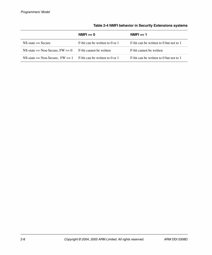
Table 2-4 on page 2-8 shows a summary of the associated software behavior.
ARM DDI 0308D Copyright © 2004, 2005 ARM Limited. All rights reserved. 2-7
Programmers’ Model
Table 2-4 NMFI behavior in Security Extensions systems
NMFI == 0 NMFI == 1
NS-state == Secure F-bit can be written to 0 or 1 F-bit can be written to 0 but not to 1
NS-state == Non-Secure, FW == 0 F-bit cannot be written F-bit cannot be written
NS-state == Non-Secure, FW == 1 F-bit can be written to 0 or 1 F-bit can be written to 0 but not to 1
2-8 Copyright © 2004, 2005 ARM Limited. All rights reserved. ARM DDI 0308D
Programmers’ Model
2.4 Exception and reset handling in Thumb state
Thumb-2 introduces a new control bit, the Thumb Exception enable (TE) bit. The TE bit controls whether exceptions are taken in ARM or Thumb state. This bit is only available in architecture variants that support the Thumb-2 instruction set. In architectures that do not support the Thumb instruction set, this bit reads as 0 and ignores writes.
The TE bit is bit[30] in CP15 register 1:
TE == 0 Exceptions are handled in ARM state. That is, on exception entry, the CPSR T and J bits are T == 0, J == 0.
TE == 1 Exceptions are handled in Thumb state. That is, on exception entry, the CPSR T and J bits are T == 1, J == 0.
There is an optional configuration input signal, CFGTE, associated with the TE bit. CFGTE controls the value of CP15 register 1 TE, and the CPSR T-bit on Reset. If a processor does not have a CFGTE input and ARM state is supported, the reset value of TE is 0.
2.4.1 TE bit and the Security Extensions
If both Thumb-2 and the Security Extensions are implemented, the TE bit is a banked bit. This separates the usage model in each security state. (The Secure and Non-Secure states have separate vector base address registers.) The TE bit has the same read/write access policy as the other CP15 register 1 banked fields in the Security Extensions architecture.
CFGTE controls both versions of the TE bit.
ARM DDI 0308D Copyright © 2004, 2005 ARM Limited. All rights reserved. 2-9
Programmers’ Model
2.5 Unaligned access support
ARMv6 introduced unaligned support for word or halfword loads and stores. The unaligned and legacy (pre-ARMv6) behavior is supported by a new system control bit, the U-bit, in combination with the existing A-bit.
See Load and store alignment checks on page 2-11 for details of the behavior of all Thumb load and store instructions.
See Unaligned exception returns on page 2-12 for details of the behavior of exception return instructions.
Note Use of U = 0 is deprecated in ARMv6T2, and obsolete from ARMv7.
From ARMv7, all accesses must comply with the U=1 alignment policy.
For more information about alignment, see the ARM Architecture Reference Manual.
2-10 Copyright © 2004, 2005 ARM Limited. All rights reserved. ARM DDI 0308D
Programmers’ Model
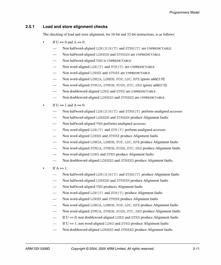
2.5.1 Load and store alignment checks
The checking of load and store alignment, for 16-bit and 32-bit instructions, is as follows:
• If U == 0 and A == 0:
— Non halfword-aligned LDR{S}H{T} and STRH{T} are UNPREDICTABLE
— Non halfword-aligned LDREXH and STREXH are UNPREDICTABLE
— Non halfword-aligned TBH is UNPREDICTABLE
— Non word-aligned LDR{T} and STR{T} are UNPREDICTABLE
— Non word-aligned LDREX and STREX are UNPREDICTABLE
— Non word-aligned LDMIA, LDMDB, POP, LDC, RFE ignore addr[1:0]
— Non word-aligned STMIA, STMDB, PUSH, STC, SRS ignore addr[1:0]
— Non doubleword-aligned LDRD and STRD are UNPREDICTABLE
— Non doubleword-aligned LDREXD and STREXD are UNPREDICTABLE.
• If U == 1 and A == 0:
— Non halfword-aligned LDR{S}H{T} and STRH{T} perform unaligned accesses
— Non halfword-aligned LDREXH and STREXH produce Alignment faults
— Non halfword-aligned TBH performs unaligned accesses
— Non word-aligned LDR{T} and STR{T} perform unaligned accesses
— Non word-aligned LDREX and STREX produce Alignment faults
— Non word-aligned LDMIA, LDMDB, POP, LDC, RFE produce Alignment faults
— Non word-aligned STMIA, STMDB, PUSH, STC, SRS produce Alignment faults
— Non word-aligned LDRD and STRD produce Alignment faults
— Non doubleword-aligned LDREXD and STREXD produce Alignment faults.
• If A == 1:
— Non halfword-aligned LDR{S}H{T} and STRH{T} produce Alignment faults
— Non halfword-aligned LDREXH and STREXH produce Alignment faults
— Non halfword-aligned TBH produces Alignment faults
— Non word-aligned LDR{T} and STR{T} produce Alignment faults
— Non word-aligned LDREX and STREX produce Alignment faults
— Non word-aligned LDMIA, LDMDB, POP, LDC, RFE produce Alignment faults
— Non word-aligned STMIA, STMDB, PUSH, STC, SRS produce Alignment faults
— If U == 0, non doubleword-aligned LDRD and STRD produce Alignment faults
— If U == 1, non word-aligned LDRD and STRD produce Alignment faults
— Non doubleword-aligned LDREXD and STREXD produce Alignment faults.
ARM DDI 0308D Copyright © 2004, 2005 ARM Limited. All rights reserved. 2-11
Programmers’ Model
2.5.2 Unaligned exception returns
An exception return instruction (RFE or SUBS PC,LR,#imm8) writes an address to the PC. The alignment of this address must be correct for the instruction set in use after the exception return. The instruction set is controlled by the (J,T) bits of the value written to the CPSR:
• For a return to ARM code ((J,T) == (0,0)), the address written to the PC must be word-aligned.
• For a return to Thumb-2 code ((J,T) == (0,1)), the address written to the PC must be halfword-aligned.
• For a return to Jazelle® opcodes ((J,T) == (1,0)), there are no alignment restrictions on the address written to the PC.
The results of breaking these rules are UNPREDICTABLE. However, no special precautions are needed in software if the instructions are used to return after a valid exception entry mechanism. A valid entry mechanism ensures that the T-bit in the SPSR and the link address bits[1:0] in R14, or the stacked equivalents for RFE, provide valid return addresses for Thumb or ARM state as appropriate.
2-12 Copyright © 2004, 2005 ARM Limited. All rights reserved. ARM DDI 0308D
Programmers’ Model
2.6 Endian support
All Thumb-2 instruction fetches are little-endian. Data accesses can be either little-endian or big-endian. For more information about endian support, see the ARM Architecture Reference Manual.
Note Use of B = 1 is deprecated in ARMv6T2, and obsolete from ARMv7.
From ARMv7, all accesses must comply with the E-bit endian support policy.
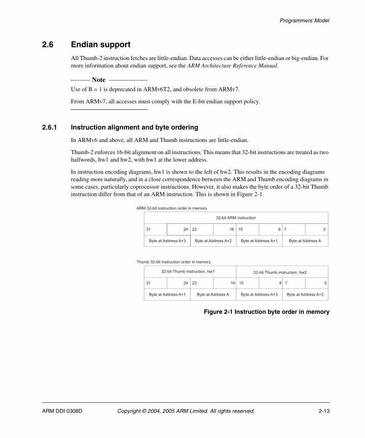
2.6.1 Instruction alignment and byte ordering
In ARMv6 and above, all ARM and Thumb instructions are little-endian.
Thumb-2 enforces 16-bit alignment on all instructions. This means that 32-bit instructions are treated as two halfwords, hw1 and hw2, with hw1 at the lower address.
In instruction encoding diagrams, hw1 is shown to the left of hw2. This results in the encoding diagrams reading more naturally, and in a close correspondence between the ARM and Thumb encoding diagrams in some cases, particularly coprocessor instructions. However, it also makes the byte order of a 32-bit Thumb instruction differ from that of an ARM instruction. This is shown in Figure 2-1.
Figure 2-1 Instruction byte order in memory
��
��������� ��������
��������������
������������ �������� ���� ������������ �������� ����
��������������
��������������
��������������
��������������
��������������
������������
������������
������������ �������� ������ ������
��������� �������� ������ ������
�� ��
��
��
�� �� ! "�#
�� ! "�#
ARM DDI 0308D Copyright © 2004, 2005 ARM Limited. All rights reserved. 2-13
Programmers’ Model
2.7 Memory stores and exclusive access
The Operation sections of instruction definitions, other than the exclusive stores, do not include pseudo-code describing exclusive access support in multiprocessor systems with shared memory. If your system has shared memory, all memory writes include the operations described by the following pseudo-code:
If (Shared(address)) then physical_address = TLB(address) ClearExclusiveByAddress(physical_address, <size>)
For more information about exclusive access support, see the ARM Architecture Reference Manual.
2-14 Copyright © 2004, 2005 ARM Limited. All rights reserved. ARM DDI 0308D
Programmers’ Model
2.8 Hardware divide support
ARMv7 introduces signed and unsigned hardware divide instructions for the R and M profiles only. See SDIV on page 4-265 and UDIV on page 4-409 for details.
In the R profile, the DZ bit in the System Control register (bit[19] of CP15 register 1) is used to support Divide-by-zero fault detection. When DZ == 1, SDIV and UDIV generate a fault on a divide-by-zero. When DZ == 0, divide-by-zero returns a zero result. DZ is cleared to zero on reset.
Note SDIV and UDIV are UNDEFINED in ARMv7-A.
ARM DDI 0308D Copyright © 2004, 2005 ARM Limited. All rights reserved. 2-15

Programmers’ Model
2-16 Copyright © 2004, 2005 ARM Limited. All rights reserved. ARM DDI 0308D
Chapter 3 The Thumb Instruction Set
This chapter describes the Thumb® instruction set. It contains the following sections:
• Instruction set encoding on page 3-2
• Instruction encoding for 32-bit Thumb instructions on page 3-12
• Conditional execution on page 3-34
• UNDEFINED and UNPREDICTABLE instruction set space on page 3-36
• Usage of 0b1111 as a register specifier in 32-bit encodings on page 3-38
• Usage of 0b1101 as a register specifier on page 3-41
• Thumb-2 and VFP support on page 3-43.
ARM DDI 0308D Copyright © 2004, 2005 ARM Limited. All rights reserved. 3-1
The Thumb Instruction Set
3.1 Instruction set encoding
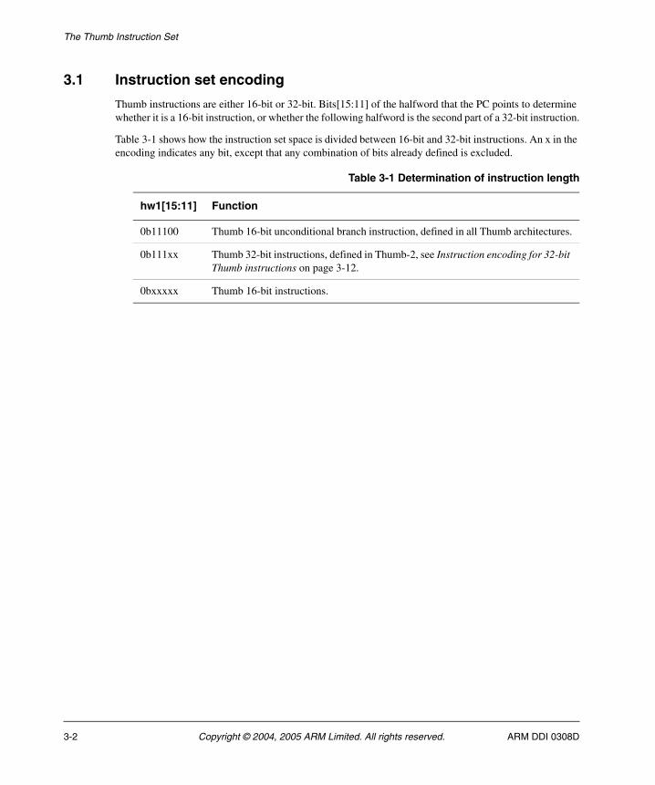
Thumb instructions are either 16-bit or 32-bit. Bits[15:11] of the halfword that the PC points to determine whether it is a 16-bit instruction, or whether the following halfword is the second part of a 32-bit instruction.
Table 3-1 shows how the instruction set space is divided between 16-bit and 32-bit instructions. An x in the encoding indicates any bit, except that any combination of bits already defined is excluded.
Table 3-1 Determination of instruction length
hw1[15:11] Function
0b11100 Thumb 16-bit unconditional branch instruction, defined in all Thumb architectures.
0b111xx Thumb 32-bit instructions, defined in Thumb-2, see Instruction encoding for 32-bit Thumb instructions on page 3-12.
0bxxxxx Thumb 16-bit instructions.
3-2 Copyright © 2004, 2005 ARM Limited. All rights reserved. ARM DDI 0308D
The Thumb Instruction Set
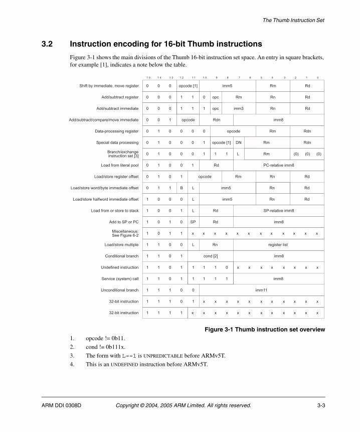
3.2 Instruction encoding for 16-bit Thumb instructions
Figure 3-1 shows the main divisions of the Thumb 16-bit instruction set space. An entry in square brackets, for example [1], indicates a note below the table.
Figure 3-1 Thumb instruction set overview1. opcode != 0b11.
2. cond != 0b111x.
3. The form with L==1 is UNPREDICTABLE before ARMv5T.
4. This is an UNDEFINED instruction before ARMv5T.
�$���� ��
�� ��
�$����%�& ��
'(���)���*����
+��,���������������*���-�����
��.����������-�����
��.�����������������
��.��������.���$���.��*����������
/����$������� -��-�����
+$����)����$������� -
0���,���)�����)$��)
0���.���������.��������������,,���
0���.�������),��������������,,���
0���,����������������1
����+'��'(
0���.�������-������,,���
����
����
+'���)���*����
� � � � � � � � � � � " 2 ! # � � � � � "
�$����%�& ���� �� ��" " "
" " "
" " "
" " �
" � "
" � "
" � "
" � �
� " "
� � "
� � �
" " "
�$� �� � ��
�$� � ������
���
�$����
��/3
" ��
� �� � ��
� 0 � ��
" 0 � ��
� " " � 0 ��
� " � " +' �� ���
" � " " " �
" � " " " � � � 0 ����� ��.�4��� -�� �������� ���%�&
�
�$����
�����))� ����5+��6�-���#�� � " � � 4 4 44 4 4 4 44 4 44
0���.�������)��$)�
(� ����� �)��� ��
7 ��,� ��� ��������
+��*���8������9��))
7 �� ����� �)��� ��
� � "
� � �
� �� �%�& ���
4 4 44 4 4 4 4� � "� � " � �
� � �� � " � � ���
" " �����
4 44 4 4 4 44 4 4� � � �
� � " " 0 � ��-�����)���
������� �������� � � � " �
������� �������� 4 4
4 44 4 4 4 44 44 4
8"9 8"9 8"9
ARM DDI 0308D Copyright © 2004, 2005 ARM Limited. All rights reserved. 3-3
The Thumb Instruction Set
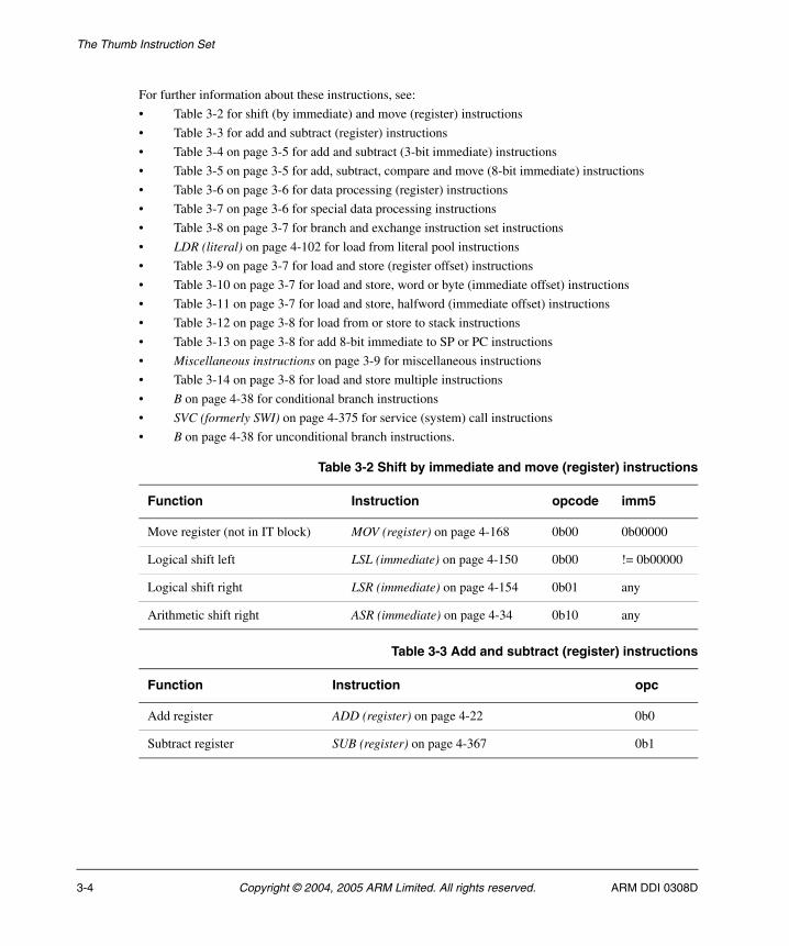
For further information about these instructions, see:
• Table 3-2 for shift (by immediate) and move (register) instructions
• Table 3-3 for add and subtract (register) instructions
• Table 3-4 on page 3-5 for add and subtract (3-bit immediate) instructions
• Table 3-5 on page 3-5 for add, subtract, compare and move (8-bit immediate) instructions
• Table 3-6 on page 3-6 for data processing (register) instructions
• Table 3-7 on page 3-6 for special data processing instructions
• Table 3-8 on page 3-7 for branch and exchange instruction set instructions
• LDR (literal) on page 4-102 for load from literal pool instructions
• Table 3-9 on page 3-7 for load and store (register offset) instructions
• Table 3-10 on page 3-7 for load and store, word or byte (immediate offset) instructions
• Table 3-11 on page 3-7 for load and store, halfword (immediate offset) instructions
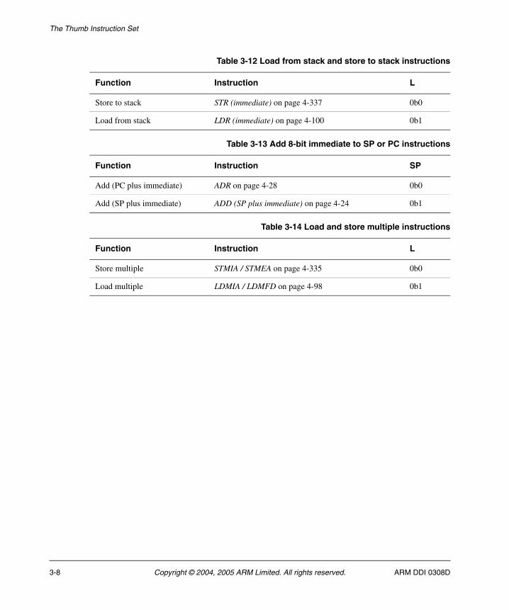
• Table 3-12 on page 3-8 for load from or store to stack instructions
• Table 3-13 on page 3-8 for add 8-bit immediate to SP or PC instructions
• Miscellaneous instructions on page 3-9 for miscellaneous instructions
• Table 3-14 on page 3-8 for load and store multiple instructions
• B on page 4-38 for conditional branch instructions
• SVC (formerly SWI) on page 4-375 for service (system) call instructions
• B on page 4-38 for unconditional branch instructions.
Table 3-2 Shift by immediate and move (register) instructions
Function Instruction opcode imm5
Move register (not in IT block) MOV (register) on page 4-168 0b00 0b00000
Logical shift left LSL (immediate) on page 4-150 0b00 != 0b00000
Logical shift right LSR (immediate) on page 4-154 0b01 any
Arithmetic shift right ASR (immediate) on page 4-34 0b10 any
Table 3-3 Add and subtract (register) instructions
Function Instruction opc
Add register ADD (register) on page 4-22 0b0
Subtract register SUB (register) on page 4-367 0b1
3-4 Copyright © 2004, 2005 ARM Limited. All rights reserved. ARM DDI 0308D
The Thumb Instruction Set
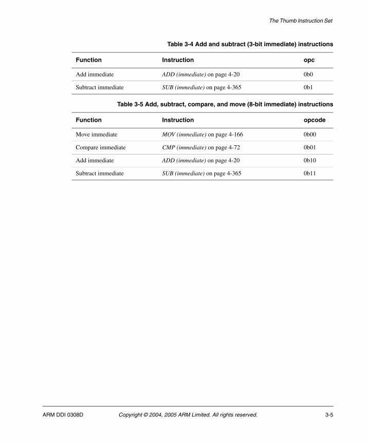
Table 3-4 Add and subtract (3-bit immediate) instructions
Function Instruction opc
Add immediate ADD (immediate) on page 4-20 0b0
Subtract immediate SUB (immediate) on page 4-365 0b1
Table 3-5 Add, subtract, compare, and move (8-bit immediate) instructions
Function Instruction opcode
Move immediate MOV (immediate) on page 4-166 0b00
Compare immediate CMP (immediate) on page 4-72 0b01
Add immediate ADD (immediate) on page 4-20 0b10
Subtract immediate SUB (immediate) on page 4-365 0b11
ARM DDI 0308D Copyright © 2004, 2005 ARM Limited. All rights reserved. 3-5
The Thumb Instruction Set
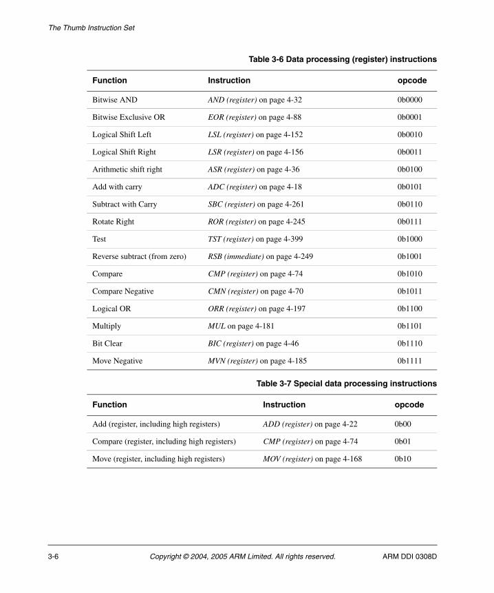
Table 3-6 Data processing (register) instructions
Function Instruction opcode
Bitwise AND AND (register) on page 4-32 0b0000
Bitwise Exclusive OR EOR (register) on page 4-88 0b0001
Logical Shift Left LSL (register) on page 4-152 0b0010
Logical Shift Right LSR (register) on page 4-156 0b0011
Arithmetic shift right ASR (register) on page 4-36 0b0100
Add with carry ADC (register) on page 4-18 0b0101
Subtract with Carry SBC (register) on page 4-261 0b0110
Rotate Right ROR (register) on page 4-245 0b0111
Test TST (register) on page 4-399 0b1000
Reverse subtract (from zero) RSB (immediate) on page 4-249 0b1001
Compare CMP (register) on page 4-74 0b1010
Compare Negative CMN (register) on page 4-70 0b1011
Logical OR ORR (register) on page 4-197 0b1100
Multiply MUL on page 4-181 0b1101
Bit Clear BIC (register) on page 4-46 0b1110
Move Negative MVN (register) on page 4-185 0b1111
Table 3-7 Special data processing instructions
Function Instruction opcode
Add (register, including high registers) ADD (register) on page 4-22 0b00
Compare (register, including high registers) CMP (register) on page 4-74 0b01
Move (register, including high registers) MOV (register) on page 4-168 0b10
3-6 Copyright © 2004, 2005 ARM Limited. All rights reserved. ARM DDI 0308D
The Thumb Instruction Set
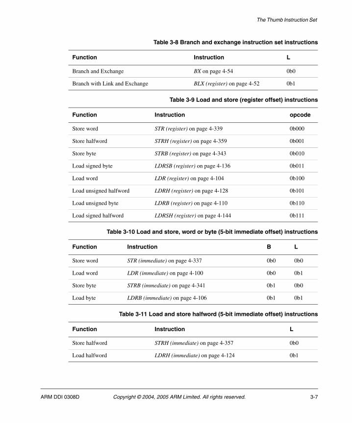
Table 3-8 Branch and exchange instruction set instructions
Function Instruction L
Branch and Exchange BX on page 4-54 0b0
Branch with Link and Exchange BLX (register) on page 4-52 0b1
Table 3-9 Load and store (register offset) instructions
Function Instruction opcode
Store word STR (register) on page 4-339 0b000
Store halfword STRH (register) on page 4-359 0b001
Store byte STRB (register) on page 4-343 0b010
Load signed byte LDRSB (register) on page 4-136 0b011
Load word LDR (register) on page 4-104 0b100
Load unsigned halfword LDRH (register) on page 4-128 0b101
Load unsigned byte LDRB (register) on page 4-110 0b110
Load signed halfword LDRSH (register) on page 4-144 0b111
Table 3-10 Load and store, word or byte (5-bit immediate offset) instructions
Function Instruction B L
Store word STR (immediate) on page 4-337 0b0 0b0
Load word LDR (immediate) on page 4-100 0b0 0b1
Store byte STRB (immediate) on page 4-341 0b1 0b0
Load byte LDRB (immediate) on page 4-106 0b1 0b1
Table 3-11 Load and store halfword (5-bit immediate offset) instructions
Function Instruction L
Store halfword STRH (immediate) on page 4-357 0b0
Load halfword LDRH (immediate) on page 4-124 0b1
ARM DDI 0308D Copyright © 2004, 2005 ARM Limited. All rights reserved. 3-7
The Thumb Instruction Set
Table 3-12 Load from stack and store to stack instructions
Function Instruction L
Store to stack STR (immediate) on page 4-337 0b0
Load from stack LDR (immediate) on page 4-100 0b1
Table 3-13 Add 8-bit immediate to SP or PC instructions
Function Instruction SP
Add (PC plus immediate) ADR on page 4-28 0b0
Add (SP plus immediate) ADD (SP plus immediate) on page 4-24 0b1
Table 3-14 Load and store multiple instructions
Function Instruction L
Store multiple STMIA / STMEA on page 4-335 0b0
Load multiple LDMIA / LDMFD on page 4-98 0b1
3-8 Copyright © 2004, 2005 ARM Limited. All rights reserved. ARM DDI 0308D

The Thumb Instruction Set
3.2.1 Miscellaneous instructions
Figure 3-2 lists miscellaneous Thumb instructions. An entry in square brackets, for example [1], indicates a note below the figure.
Figure 3-2 Miscellaneous Thumb instructions1. This is an UNDEFINED instruction before ARMv5.
2. These are UNDEFINED instructions before ARMv6.
3. These are UNDEFINED instructions before Thumb-2.
Note Any instruction with bits[15:12] = 1011, that is not shown in Figure 3-2, is an UNDEFINED instruction.
For further information about these instructions, see:
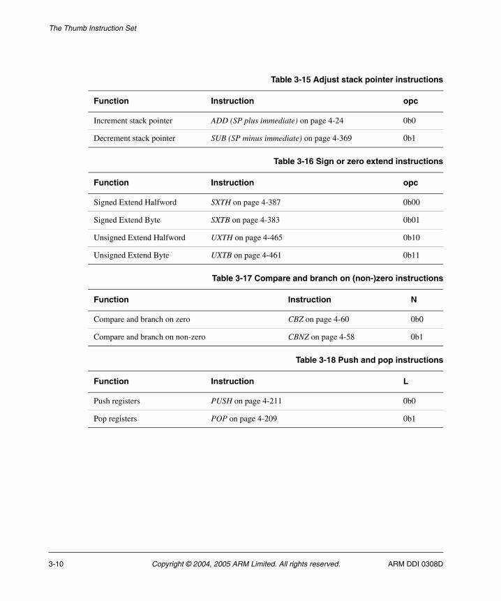
• Table 3-15 on page 3-10 for adjust stack pointer instructions
• Table 3-16 on page 3-10 for sign or zero extend instructions
• Table 3-17 on page 3-10 for compare (non-)zero and branch instructions
• Table 3-18 on page 3-10 for push and pop instructions
• SETEND on page 4-269 for the set endianness instruction
• CPS on page 4-76 for the change processor state instruction
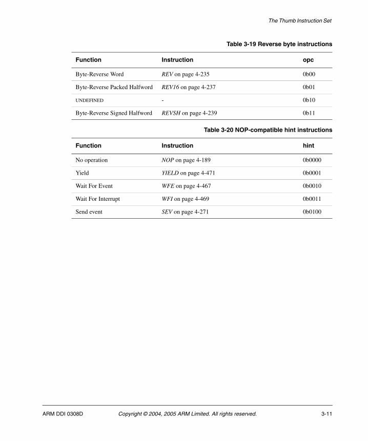
• Table 3-19 on page 3-11 for reverse bytes instructions
• BKPT on page 4-48 for the software breakpoint instruction
• IT on page 4-92 for the If-Then instruction
• Table 3-20 on page 3-11 for NOP-compatible hint instructions.
�:�������1$�� ���
'���.$�$��-�����)���
" " "� " � � " �$� ���!
� " � � 0 � ��-�����)���� "
� " � �
" "� �
(�� -�'��������+����%�&
��*���������%�&
� " � �
� " � " � ���$�
+�,���������1$�� �%�&
� " � �
� " ��� � �
" �
� "�� 6;
� " � � " "" � �� ���$�+�- .<����4�� �%�&
� " � �
+��= ��� ���%�&
" "� � " �
" � =
" "� �� " � � " �
" "� �� " � � " �
73'�=/;(��0=
73'�=/;(��0= " "
4 ��
4 4 4 4
4 4 4
� � � � � � � � � � � " 2 ! # � � � � � "
(��$���� ���� ��� 83� �9>���%�& � " � � 3 " � � ���� �
;,���� � �������� �%�&
3?'����$����)��� ��%�&
� � �� " � �
� � �� " � �
�
�
�� � ���18@A"�""""9
" " ""�� �
8"9 8"9 8"9
ARM DDI 0308D Copyright © 2004, 2005 ARM Limited. All rights reserved. 3-9
The Thumb Instruction Set
Table 3-15 Adjust stack pointer instructions
Function Instruction opc
Increment stack pointer ADD (SP plus immediate) on page 4-24 0b0
Decrement stack pointer SUB (SP minus immediate) on page 4-369 0b1
Table 3-16 Sign or zero extend instructions
Function Instruction opc
Signed Extend Halfword SXTH on page 4-387 0b00
Signed Extend Byte SXTB on page 4-383 0b01
Unsigned Extend Halfword UXTH on page 4-465 0b10
Unsigned Extend Byte UXTB on page 4-461 0b11
Table 3-17 Compare and branch on (non-)zero instructions
Function Instruction N
Compare and branch on zero CBZ on page 4-60 0b0
Compare and branch on non-zero CBNZ on page 4-58 0b1
Table 3-18 Push and pop instructions
Function Instruction L
Push registers PUSH on page 4-211 0b0
Pop registers POP on page 4-209 0b1
3-10 Copyright © 2004, 2005 ARM Limited. All rights reserved. ARM DDI 0308D
The Thumb Instruction Set
Table 3-19 Reverse byte instructions
Function Instruction opc
Byte-Reverse Word REV on page 4-235 0b00
Byte-Reverse Packed Halfword REV16 on page 4-237 0b01
UNDEFINED - 0b10
Byte-Reverse Signed Halfword REVSH on page 4-239 0b11
Table 3-20 NOP-compatible hint instructions
Function Instruction hint
No operation NOP on page 4-189 0b0000
Yield YIELD on page 4-471 0b0001
Wait For Event WFE on page 4-467 0b0010
Wait For Interrupt WFI on page 4-469 0b0011
Send event SEV on page 4-271 0b0100
ARM DDI 0308D Copyright © 2004, 2005 ARM Limited. All rights reserved. 3-11
The Thumb Instruction Set
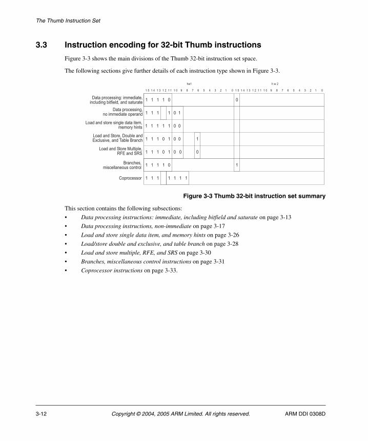
3.3 Instruction encoding for 32-bit Thumb instructions
Figure 3-3 shows the main divisions of the Thumb 32-bit instruction set space.
The following sections give further details of each instruction type shown in Figure 3-3.
Figure 3-3 Thumb 32-bit instruction set summary
This section contains the following subsections:
• Data processing instructions: immediate, including bitfield and saturate on page 3-13
• Data processing instructions, non-immediate on page 3-17
• Load and store single data item, and memory hints on page 3-26
• Load/store double and exclusive, and table branch on page 3-28
• Load and store multiple, RFE, and SRS on page 3-30
• Branches, miscellaneous control instructions on page 3-31
• Coprocessor instructions on page 3-33.
" "�
� � �
� � � � � � � � � � � " 2 ! # � � � � � "� � � � � � � � � � � " 2 ! # � � � � � "
� � ����
/���$������� -� �����������$��� �
� � �
� � �
� � �
�� � �
/���$������� -5����������� �)��� -���,��)��� ���������
"�
�
�
�
"
"
�
�
""
""
�
"
0���� �������� -)������������������ ��
0���� �+������)��$)���6=� �+�+
0���� �+�����/���)�� �=4�)���*��� ����)���� ��
(�$��������
��� ����������))� ������ ���) � � � � "
� � � � � � �
""
3-12 Copyright © 2004, 2005 ARM Limited. All rights reserved. ARM DDI 0308D
The Thumb Instruction Set
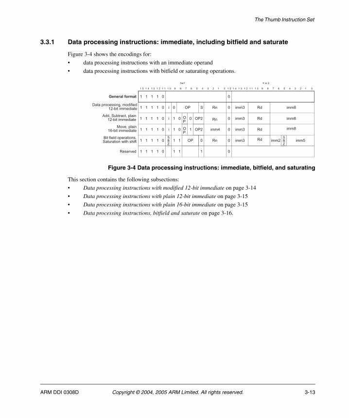
3.3.1 Data processing instructions: immediate, including bitfield and saturate
Figure 3-4 shows the encodings for:
• data processing instructions with an immediate operand
• data processing instructions with bitfield or saturating operations.
Figure 3-4 Data processing instructions: immediate, bitfield, and saturating
This section contains the following subsections:
• Data processing instructions with modified 12-bit immediate on page 3-14
• Data processing instructions with plain 12-bit immediate on page 3-15
• Data processing instructions with plain 16-bit immediate on page 3-15
• Data processing instructions, bitfield and saturate on page 3-16.
" "
+�>
�
� � �
� � � � � � � � � � � " 2 ! # � � � � � "� � � � � � � � � � � " 2 ! # � � � � � "
� � ����
/���$������� -�����,������������������
� � �
� � �
�� � �
�
� � �
������������
"
"
"
""�
�
�
�
"
"
"
�
�
+�>
�
�
� "
"
" ?'
"?'
?'
?'�
?'��
?' "
�
�
�
��
��
��
�����+��������$)��
���������������
���,��)��$������ ��+�������� �������,�
��*��$)�� �#�������������
+
����
"�� � � �� " ������*��
����
����
����
����
���
���
���
����
����
ARM DDI 0308D Copyright © 2004, 2005 ARM Limited. All rights reserved. 3-13
The Thumb Instruction Set
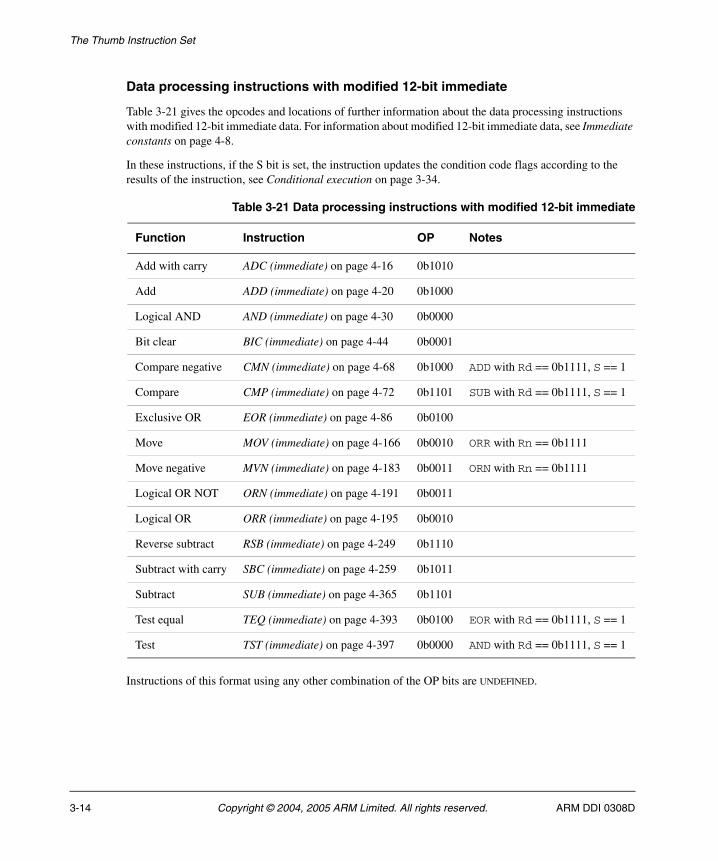
Data processing instructions with modified 12-bit immediate
Table 3-21 gives the opcodes and locations of further information about the data processing instructions with modified 12-bit immediate data. For information about modified 12-bit immediate data, see Immediate constants on page 4-8.
In these instructions, if the S bit is set, the instruction updates the condition code flags according to the results of the instruction, see Conditional execution on page 3-34.
Instructions of this format using any other combination of the OP bits are UNDEFINED.
Table 3-21 Data processing instructions with modified 12-bit immediate
Function Instruction OP Notes
Add with carry ADC (immediate) on page 4-16 0b1010
Add ADD (immediate) on page 4-20 0b1000
Logical AND AND (immediate) on page 4-30 0b0000
Bit clear BIC (immediate) on page 4-44 0b0001
Compare negative CMN (immediate) on page 4-68 0b1000 ADD with Rd == 0b1111, S == 1
Compare CMP (immediate) on page 4-72 0b1101 SUB with Rd == 0b1111, S == 1
Exclusive OR EOR (immediate) on page 4-86 0b0100
Move MOV (immediate) on page 4-166 0b0010 ORR with Rn == 0b1111
Move negative MVN (immediate) on page 4-183 0b0011 ORN with Rn == 0b1111
Logical OR NOT ORN (immediate) on page 4-191 0b0011
Logical OR ORR (immediate) on page 4-195 0b0010
Reverse subtract RSB (immediate) on page 4-249 0b1110
Subtract with carry SBC (immediate) on page 4-259 0b1011
Subtract SUB (immediate) on page 4-365 0b1101
Test equal TEQ (immediate) on page 4-393 0b0100 EOR with Rd == 0b1111, S == 1
Test TST (immediate) on page 4-397 0b0000 AND with Rd == 0b1111, S == 1
3-14 Copyright © 2004, 2005 ARM Limited. All rights reserved. ARM DDI 0308D
The Thumb Instruction Set
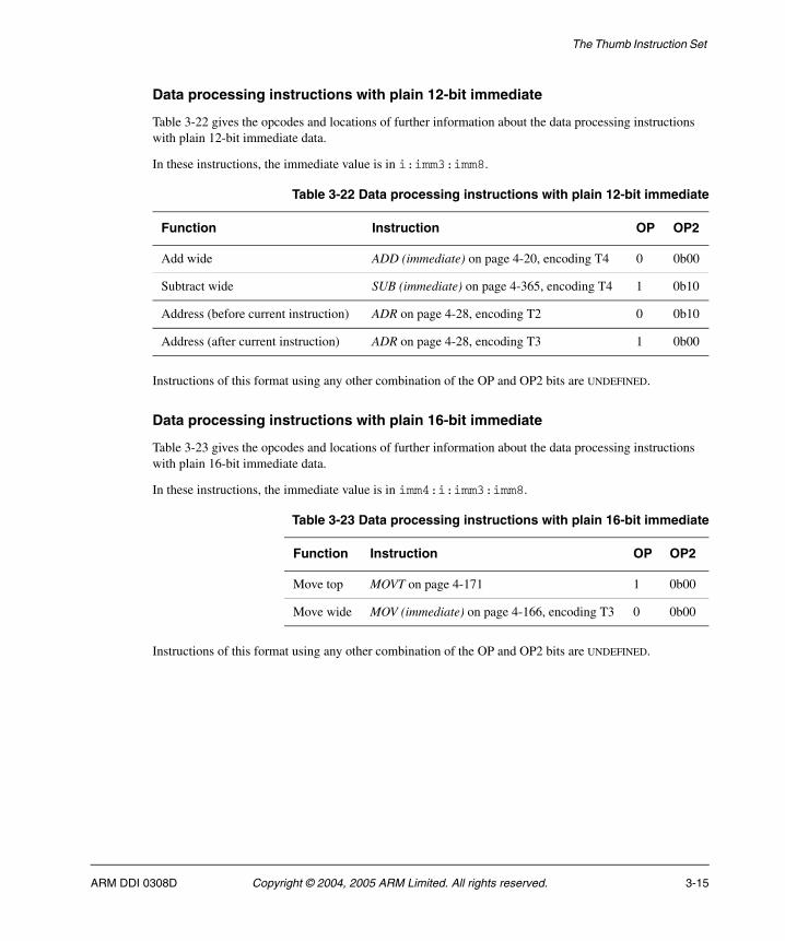
Data processing instructions with plain 12-bit immediate
Table 3-22 gives the opcodes and locations of further information about the data processing instructions with plain 12-bit immediate data.
In these instructions, the immediate value is in i:imm3:imm8.
Instructions of this format using any other combination of the OP and OP2 bits are UNDEFINED.
Data processing instructions with plain 16-bit immediate
Table 3-23 gives the opcodes and locations of further information about the data processing instructions with plain 16-bit immediate data.
In these instructions, the immediate value is in imm4:i:imm3:imm8.
Instructions of this format using any other combination of the OP and OP2 bits are UNDEFINED.
Table 3-22 Data processing instructions with plain 12-bit immediate
Function Instruction OP OP2
Add wide ADD (immediate) on page 4-20, encoding T4 0 0b00
Subtract wide SUB (immediate) on page 4-365, encoding T4 1 0b10
Address (before current instruction) ADR on page 4-28, encoding T2 0 0b10
Address (after current instruction) ADR on page 4-28, encoding T3 1 0b00
Table 3-23 Data processing instructions with plain 16-bit immediate
Function Instruction OP OP2
Move top MOVT on page 4-171 1 0b00
Move wide MOV (immediate) on page 4-166, encoding T3 0 0b00
ARM DDI 0308D Copyright © 2004, 2005 ARM Limited. All rights reserved. 3-15

The Thumb Instruction Set
Data processing instructions, bitfield and saturate
Table 3-24 gives the opcodes and locations of further information about saturation, bitfield extract, clear, and insert instructions.
Instructions of this format using any other combination of the OP bits are UNDEFINED.
Table 3-24 Miscellaneous data processing instructions
Function Instruction OP Notes
Bit Field Clear BFC on page 4-40 0b011 Rn == 0b1111, meaning #0
Bit Field Insert BFI on page 4-42 0b011
Signed Bit Field extract SBFX on page 4-263 0b010
Signed saturate, LSL SSAT on page 4-321 0b000
Signed saturate, ASR SSAT on page 4-321 0b001
Signed saturate 16-bit SSAT16 on page 4-323 0b001 shift_imm == 0
Unsigned Bit Field extract UBFX on page 4-407 0b110
Unsigned saturate, LSL USAT on page 4-445 0b100
Unsigned saturate, ASR USAT on page 4-445 0b101
Unsigned saturate 16-bit USAT16 on page 4-447 0b101 shift_imm == 0
3-16 Copyright © 2004, 2005 ARM Limited. All rights reserved. ARM DDI 0308D
The Thumb Instruction Set
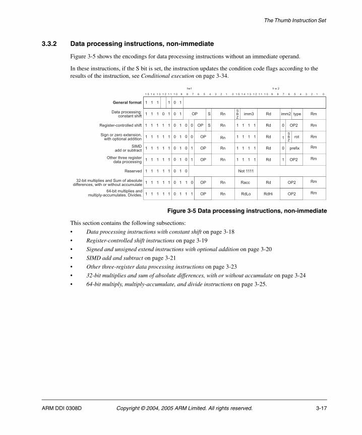
3.3.2 Data processing instructions, non-immediate
Figure 3-5 shows the encodings for data processing instructions without an immediate operand.
In these instructions, if the S bit is set, the instruction updates the condition code flags according to the results of the instruction, see Conditional execution on page 3-34.
Figure 3-5 Data processing instructions, non-immediate
This section contains the following subsections:
• Data processing instructions with constant shift on page 3-18
• Register-controlled shift instructions on page 3-19
• Signed and unsigned extend instructions with optional addition on page 3-20
• SIMD add and subtract on page 3-21
• Other three-register data processing instructions on page 3-23
• 32-bit multiplies and sum of absolute differences, with or without accumulate on page 3-24
• 64-bit multiply, multiply-accumulate, and divide instructions on page 3-25.
��
?�����������-���������$������� -
�
"
�
�����*��
�
� � � � � � � � � � � " 2 ! # � � � � � "� � � � � � � � � � � " 2 ! # � � � � � "
� � ����
� � �
� � � � �
� � � �
""� � � �
�
�� � �
� � � �
������������
�
�
�
�
�
"
"
�
�
"
"
�
�
" �
"
"
"
"
"
� � � �� " �
��
��
��
��
��
�
�
�
�
�
�
��
��
��
��
��
��0� ��B�
?'
?'
?'
?'
?'
?'
��
"
"
�
�
� � �
� � �
� � �
�
�
�
� � � �
3������
?'�
+
+
+�>
?'�
$��,�4
���
?'�
+�>
"
�
"
�
/���$������� -5�� ��� ����,�
��-�������� ���))�����,�
+�- ��<����4�� ��� ������$��� �)�������
+;�/�������������
��������)��$)���� �+���,����)�����,,��� �����������������������)���
#�������)��$)���� ���)��$)��������)����C/�*����C
� � � �� " � � ��?'"� ?'����� ��
��
���� ���� ��$�
ARM DDI 0308D Copyright © 2004, 2005 ARM Limited. All rights reserved. 3-17
The Thumb Instruction Set
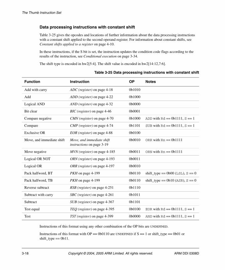
Data processing instructions with constant shift
Table 3-25 gives the opcodes and locations of further information about the data processing instructions with a constant shift applied to the second operand register. For information about constant shifts, see Constant shifts applied to a register on page 4-10.
In these instructions, if the S bit is set, the instruction updates the condition code flags according to the results of the instruction, see Conditional execution on page 3-34.
The shift type is encoded in hw2[5:4]. The shift value is encoded in hw2[14:12,7:6].
Instructions of this format using any other combination of the OP bits are UNDEFINED.
Instructions of this format with OP == 0b0110 are UNDEFINED if S == 1 or shift_type == 0b01 or shift_type == 0b11.
Table 3-25 Data processing instructions with constant shift
Function Instruction OP Notes
Add with carry ADC (register) on page 4-18 0b1010
Add ADD (register) on page 4-22 0b1000
Logical AND AND (register) on page 4-32 0b0000
Bit clear BIC (register) on page 4-46 0b0001
Compare negative CMN (register) on page 4-70 0b1000 ADD with Rd == 0b1111, S == 1
Compare CMP (register) on page 4-74 0b1101 SUB with Rd == 0b1111, S == 1
Exclusive OR EOR (register) on page 4-88 0b0100
Move, and immediate shift Move, and immediate shift instructions on page 3-19
0b0010 ORR with Rn == 0b1111
Move negative MVN (register) on page 4-185 0b0011 ORN with Rn == 0b1111
Logical OR NOT ORN (register) on page 4-193 0b0011
Logical OR ORR (register) on page 4-197 0b0010
Pack halfword, BT PKH on page 4-199 0b0110 shift_type == 0b00 (LSL), S == 0
Pack halfword, TB PKH on page 4-199 0b0110 shift_type == 0b10 (ASR), S == 0
Reverse subtract RSB (register) on page 4-251 0b1110
Subtract with carry SBC (register) on page 4-261 0b1011
Subtract SUB (register) on page 4-367 0b1101
Test equal TEQ (register) on page 4-395 0b0100 EOR with Rd == 0b1111, S == 1
Test TST (register) on page 4-399 0b0000 AND with Rd == 0b1111, S == 1
3-18 Copyright © 2004, 2005 ARM Limited. All rights reserved. ARM DDI 0308D
The Thumb Instruction Set
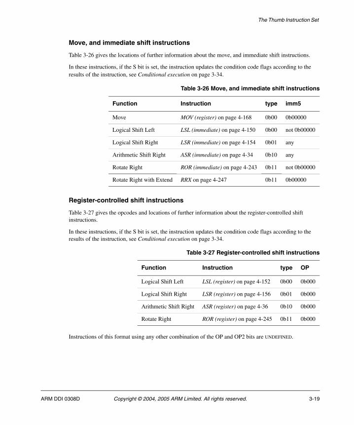
Move, and immediate shift instructions
Table 3-26 gives the locations of further information about the move, and immediate shift instructions.
In these instructions, if the S bit is set, the instruction updates the condition code flags according to the results of the instruction, see Conditional execution on page 3-34.
Register-controlled shift instructions
Table 3-27 gives the opcodes and locations of further information about the register-controlled shift instructions.
In these instructions, if the S bit is set, the instruction updates the condition code flags according to the results of the instruction, see Conditional execution on page 3-34.
Instructions of this format using any other combination of the OP and OP2 bits are UNDEFINED.
Table 3-26 Move, and immediate shift instructions
Function Instruction type imm5
Move MOV (register) on page 4-168 0b00 0b00000
Logical Shift Left LSL (immediate) on page 4-150 0b00 not 0b00000
Logical Shift Right LSR (immediate) on page 4-154 0b01 any
Arithmetic Shift Right ASR (immediate) on page 4-34 0b10 any
Rotate Right ROR (immediate) on page 4-243 0b11 not 0b00000
Rotate Right with Extend RRX on page 4-247 0b11 0b00000
Table 3-27 Register-controlled shift instructions
Function Instruction type OP
Logical Shift Left LSL (register) on page 4-152 0b00 0b000
Logical Shift Right LSR (register) on page 4-156 0b01 0b000
Arithmetic Shift Right ASR (register) on page 4-36 0b10 0b000
Rotate Right ROR (register) on page 4-245 0b11 0b000
ARM DDI 0308D Copyright © 2004, 2005 ARM Limited. All rights reserved. 3-19
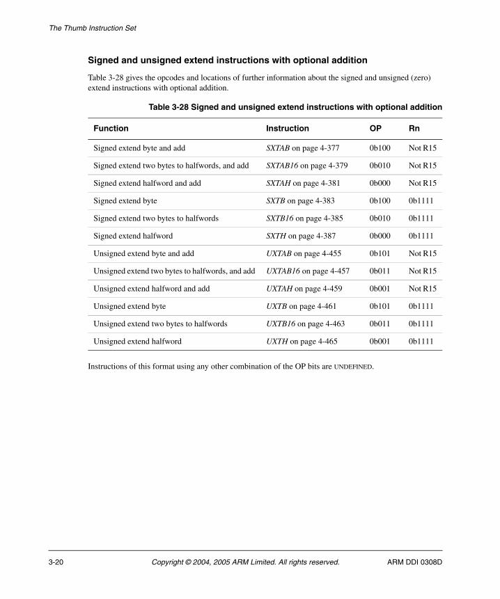
The Thumb Instruction Set
Signed and unsigned extend instructions with optional addition
Table 3-28 gives the opcodes and locations of further information about the signed and unsigned (zero) extend instructions with optional addition.
Instructions of this format using any other combination of the OP bits are UNDEFINED.
Table 3-28 Signed and unsigned extend instructions with optional addition
Function Instruction OP Rn
Signed extend byte and add SXTAB on page 4-377 0b100 Not R15
Signed extend two bytes to halfwords, and add SXTAB16 on page 4-379 0b010 Not R15
Signed extend halfword and add SXTAH on page 4-381 0b000 Not R15
Signed extend byte SXTB on page 4-383 0b100 0b1111
Signed extend two bytes to halfwords SXTB16 on page 4-385 0b010 0b1111
Signed extend halfword SXTH on page 4-387 0b000 0b1111
Unsigned extend byte and add UXTAB on page 4-455 0b101 Not R15
Unsigned extend two bytes to halfwords, and add UXTAB16 on page 4-457 0b011 Not R15
Unsigned extend halfword and add UXTAH on page 4-459 0b001 Not R15
Unsigned extend byte UXTB on page 4-461 0b101 0b1111
Unsigned extend two bytes to halfwords UXTB16 on page 4-463 0b011 0b1111
Unsigned extend halfword UXTH on page 4-465 0b001 0b1111
3-20 Copyright © 2004, 2005 ARM Limited. All rights reserved. ARM DDI 0308D
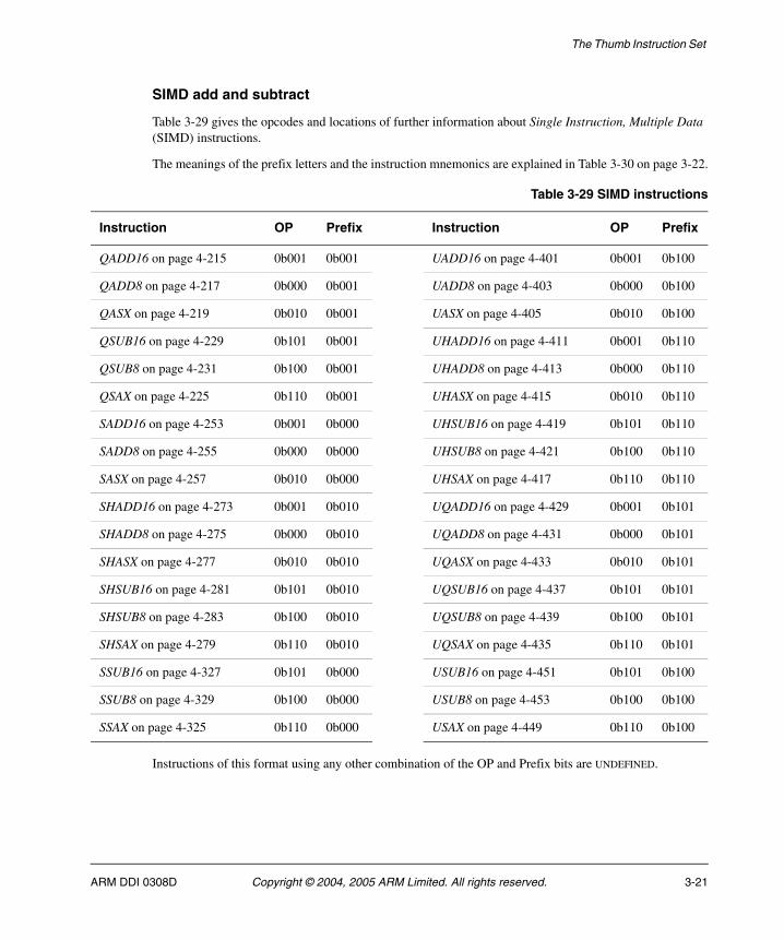
The Thumb Instruction Set
SIMD add and subtract
Table 3-29 gives the opcodes and locations of further information about Single Instruction, Multiple Data (SIMD) instructions.
The meanings of the prefix letters and the instruction mnemonics are explained in Table 3-30 on page 3-22.
Instructions of this format using any other combination of the OP and Prefix bits are UNDEFINED.
Table 3-29 SIMD instructions
Instruction OP Prefix Instruction OP Prefix
QADD16 on page 4-215 0b001 0b001 UADD16 on page 4-401 0b001 0b100
QADD8 on page 4-217 0b000 0b001 UADD8 on page 4-403 0b000 0b100
QASX on page 4-219 0b010 0b001 UASX on page 4-405 0b010 0b100
QSUB16 on page 4-229 0b101 0b001 UHADD16 on page 4-411 0b001 0b110
QSUB8 on page 4-231 0b100 0b001 UHADD8 on page 4-413 0b000 0b110
QSAX on page 4-225 0b110 0b001 UHASX on page 4-415 0b010 0b110
SADD16 on page 4-253 0b001 0b000 UHSUB16 on page 4-419 0b101 0b110
SADD8 on page 4-255 0b000 0b000 UHSUB8 on page 4-421 0b100 0b110
SASX on page 4-257 0b010 0b000 UHSAX on page 4-417 0b110 0b110
SHADD16 on page 4-273 0b001 0b010 UQADD16 on page 4-429 0b001 0b101
SHADD8 on page 4-275 0b000 0b010 UQADD8 on page 4-431 0b000 0b101
SHASX on page 4-277 0b010 0b010 UQASX on page 4-433 0b010 0b101
SHSUB16 on page 4-281 0b101 0b010 UQSUB16 on page 4-437 0b101 0b101
SHSUB8 on page 4-283 0b100 0b010 UQSUB8 on page 4-439 0b100 0b101
SHSAX on page 4-279 0b110 0b010 UQSAX on page 4-435 0b110 0b101
SSUB16 on page 4-327 0b101 0b000 USUB16 on page 4-451 0b101 0b100
SSUB8 on page 4-329 0b100 0b000 USUB8 on page 4-453 0b100 0b100
SSAX on page 4-325 0b110 0b000 USAX on page 4-449 0b110 0b100
ARM DDI 0308D Copyright © 2004, 2005 ARM Limited. All rights reserved. 3-21
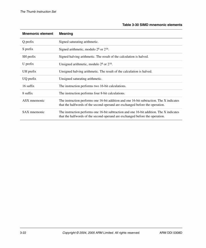
The Thumb Instruction Set
Table 3-30 SIMD mnemonic elements
Mnemonic element Meaning
Q prefix Signed saturating arithmetic.
S prefix Signed arithmetic, modulo 28 or 216.
SH prefix Signed halving arithmetic. The result of the calculation is halved.
U prefix Unsigned arithmetic, modulo 28 or 216.
UH prefix Unsigned halving arithmetic. The result of the calculation is halved.
UQ prefix Unsigned saturating arithmetic.
16 suffix The instruction performs two 16-bit calculations.
8 suffix The instruction performs four 8-bit calculations.
ASX mnemonic The instruction performs one 16-bit addition and one 16-bit subtraction. The X indicates that the halfwords of the second operand are exchanged before the operation.
SAX mnemonic The instruction performs one 16-bit subtraction and one 16-bit addition. The X indicates that the halfwords of the second operand are exchanged before the operation.
3-22 Copyright © 2004, 2005 ARM Limited. All rights reserved. ARM DDI 0308D
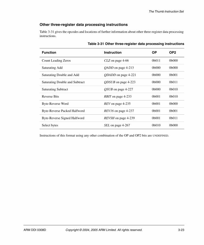
The Thumb Instruction Set
Other three-register data processing instructions
Table 3-31 gives the opcodes and locations of further information about other three-register data processing instructions.
Instructions of this format using any other combination of the OP and OP2 bits are UNDEFINED.
Table 3-31 Other three-register data processing instructions
Function Instruction OP OP2
Count Leading Zeros CLZ on page 4-66 0b011 0b000
Saturating Add QADD on page 4-213 0b000 0b000
Saturating Double and Add QDADD on page 4-221 0b000 0b001
Saturating Double and Subtract QDSUB on page 4-223 0b000 0b011
Saturating Subtract QSUB on page 4-227 0b000 0b010
Reverse Bits RBIT on page 4-233 0b001 0b010
Byte-Reverse Word REV on page 4-235 0b001 0b000
Byte-Reverse Packed Halfword REV16 on page 4-237 0b001 0b001
Byte-Reverse Signed Halfword REVSH on page 4-239 0b001 0b011
Select bytes SEL on page 4-267 0b010 0b000
ARM DDI 0308D Copyright © 2004, 2005 ARM Limited. All rights reserved. 3-23

The Thumb Instruction Set
32-bit multiplies and sum of absolute differences, with or without accumulate
Table 3-32 gives the opcodes and locations of further information about multiply and multiply-accumulate instructions with 32-bit results, and absolute difference and accumulate absolute difference instructions.
Instructions of this format using any other combination of the OP and OP2 bits are UNDEFINED.
An instruction that matches the OP and OP2 fields, but not the Ra column, is UNPREDICTABLE under the usage rules for R15.
Table 3-32 Other two-register data processing instructions
Function Instruction OP OP2 Ra
32 + 32 x 32-bit, least significant word MLA on page 4-162 0b000 0b0000 not R15
32 – 32 x 32-bit, least significant word MLS on page 4-164 0b000 0b0001 not R15
32 x 32-bit, least significant 32-bit word MUL on page 4-181 0b000 0b0000 0b1111
32 + 16 x 16-bit, 32-bit result SMLABB, SMLABT, SMLATB, SMLATT on page 4-287
0b001 0b00xx not R15
Signed Dual Multiply-Accumulate Add SMLAD on page 4-289 0b010 0b000x not R15
Signed 32 + 16 x 32-bit, most significant word SMLAWB, SMLAWT on page 4-297
0b011 0b000x not R15
Signed Dual Multiply Subtract and Accumulate SMLSD on page 4-299 0b100 0b000x not R15
Signed 32 + 32 x 32-bit, most significant word SMMLA on page 4-303 0b101 0b000x not R15
Signed 32 – 32 x 32-bit, most significant word SMMLS on page 4-305 0b110 0b000x not R15
Signed 32 x 32-bit, most significant 32-bit word SMMUL on page 4-307 0b101 0b000x 0b1111
Signed Dual Multiply Add SMUAD on page 4-309 0b010 0b000x 0b1111
16 x 16-bit, 32-bit result SMULBB, SMULBT, SMULTB, SMULTT on page 4-311
0b001 0b00xx 0b1111
Signed 16 x 32-bit, most significant 32-bit word SMULWB, SMULWT on page 4-315
0b011 0b000x 0b1111
Signed Dual Multiply Subtract SMUSD on page 4-317 0b100 0b000x 0b1111
Unsigned Sum of Absolute Differences USAD8 on page 4-441 0b111 0b0000 0b1111
Unsigned Accumulate Absolute Differences USADA8 on page 4-443 0b111 0b0000 not R15
3-24 Copyright © 2004, 2005 ARM Limited. All rights reserved. ARM DDI 0308D
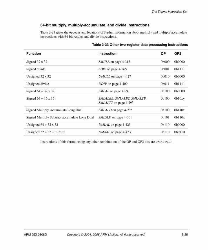
The Thumb Instruction Set
64-bit multiply, multiply-accumulate, and divide instructions
Table 3-33 gives the opcodes and locations of further information about multiply and multiply accumulate instructions with 64-bit results, and divide instructions.
Instructions of this format using any other combination of the OP and OP2 bits are UNDEFINED.
Table 3-33 Other two-register data processing instructions
Function Instruction OP OP2
Signed 32 x 32 SMULL on page 4-313 0b000 0b0000
Signed divide SDIV on page 4-265 0b001 0b1111
Unsigned 32 x 32 UMULL on page 4-427 0b010 0b0000
Unsigned divide UDIV on page 4-409 0b011 0b1111
Signed 64 + 32 x 32 SMLAL on page 4-291 0b100 0b0000
Signed 64 + 16 x 16 SMLALBB, SMLALBT, SMLALTB, SMLALTT on page 4-293
0b100 0b10xy
Signed Multiply Accumulate Long Dual SMLALD on page 4-295 0b100 0b110x
Signed Multiply Subtract accumulate Long Dual SMLSLD on page 4-301 0b101 0b110x
Unsigned 64 + 32 x 32 UMLAL on page 4-425 0b110 0b0000
Unsigned 32 + 32 + 32 x 32 UMAAL on page 4-423 0b110 0b0110
ARM DDI 0308D Copyright © 2004, 2005 ARM Limited. All rights reserved. 3-25
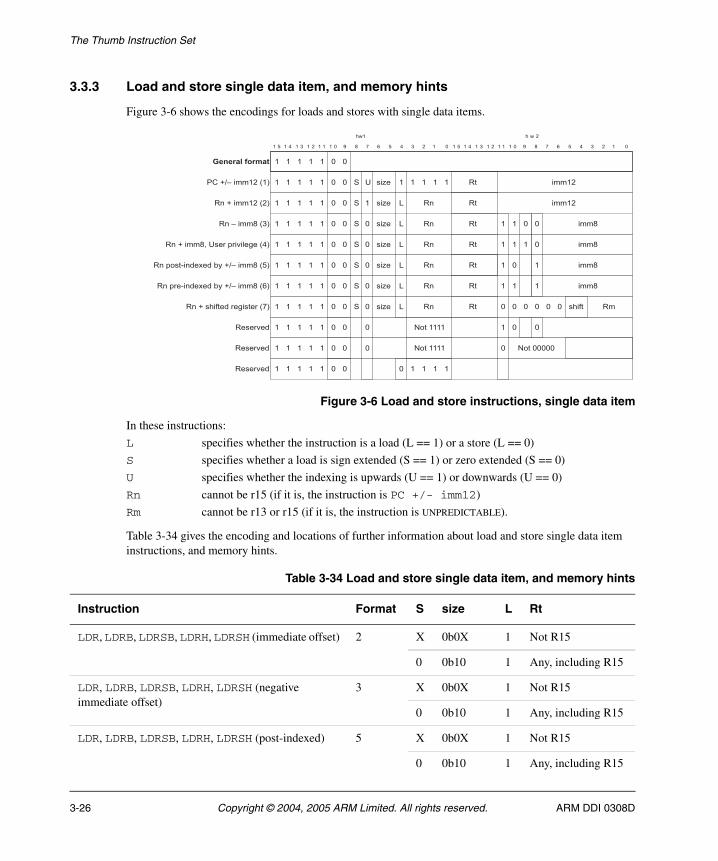
The Thumb Instruction Set
3.3.3 Load and store single data item, and memory hints
Figure 3-6 shows the encodings for loads and stores with single data items.
Figure 3-6 Load and store instructions, single data item
In these instructions:
L specifies whether the instruction is a load (L == 1) or a store (L == 0)
S specifies whether a load is sign extended (S == 1) or zero extended (S == 0)
U specifies whether the indexing is upwards (U == 1) or downwards (U == 0)
Rn cannot be r15 (if it is, the instruction is PC +/- imm12)
Rm cannot be r13 or r15 (if it is, the instruction is UNPREDICTABLE).
Table 3-34 gives the encoding and locations of further information about load and store single data item instructions, and memory hints.
" "
� � � � � � � � � � � " 2 ! # � � � � � "� � � � � � � � � � � " 2 ! # � � � � � "
� � ����
� � � ��������������
" "� � � ��
" "� � � ��
" "� � � ��
" "� � � ��
" "� � � ��
" "� � � ��
" "� � � ��
" "� � � ��
�����*��
� ����,�����-�����8!9
7
��<�+ ��
��
��
��
�����
�����
" 3������
�
�
�
+
+
+
��<�
��<�
��<�
�
"
"
0
0
0
� "
" 3��"""""
" " " " "
���
�����,�
'(�.D�����8�9
� ������8�9
� D��� 8�9
� $����� ��4�����.D��� 8�9
�����*��
�
" "� � � ��
"
� � ��
� ���� �7���$��*�)�-�8�9
� $���� ��4�����.D��� 8#9
+
+
+
"
"
"
"
�
0
0
0
��<�
��<�
��<�
��
��
���
�
3������
���
���
���
�
�
�
�
�
� �
�
�
�
" "
"
"
"
�����*�� " "� � � �� � � ��"
Table 3-34 Load and store single data item, and memory hints
Instruction Format S size L Rt
LDR, LDRB, LDRSB, LDRH, LDRSH (immediate offset) 2 X 0b0X 1 Not R15
0 0b10 1 Any, including R15
LDR, LDRB, LDRSB, LDRH, LDRSH (negative immediate offset)
3 X 0b0X 1 Not R15
0 0b10 1 Any, including R15
LDR, LDRB, LDRSB, LDRH, LDRSH (post-indexed) 5 X 0b0X 1 Not R15
0 0b10 1 Any, including R15
3-26 Copyright © 2004, 2005 ARM Limited. All rights reserved. ARM DDI 0308D
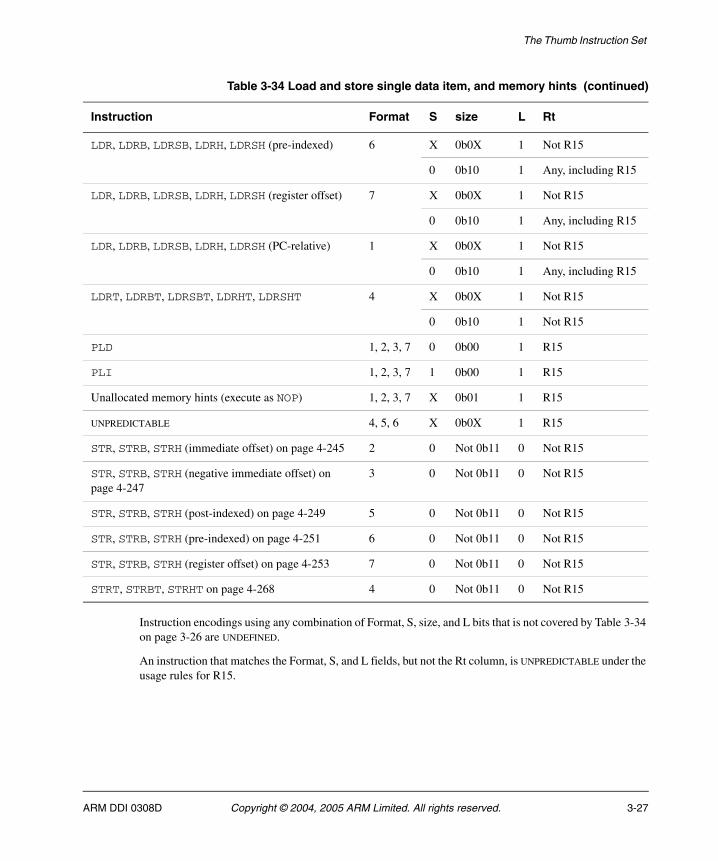
The Thumb Instruction Set
Instruction encodings using any combination of Format, S, size, and L bits that is not covered by Table 3-34 on page 3-26 are UNDEFINED.
An instruction that matches the Format, S, and L fields, but not the Rt column, is UNPREDICTABLE under the usage rules for R15.
LDR, LDRB, LDRSB, LDRH, LDRSH (pre-indexed) 6 X 0b0X 1 Not R15
0 0b10 1 Any, including R15
LDR, LDRB, LDRSB, LDRH, LDRSH (register offset) 7 X 0b0X 1 Not R15
0 0b10 1 Any, including R15
LDR, LDRB, LDRSB, LDRH, LDRSH (PC-relative) 1 X 0b0X 1 Not R15
0 0b10 1 Any, including R15
LDRT, LDRBT, LDRSBT, LDRHT, LDRSHT 4 X 0b0X 1 Not R15
0 0b10 1 Not R15
PLD 1, 2, 3, 7 0 0b00 1 R15
PLI 1, 2, 3, 7 1 0b00 1 R15
Unallocated memory hints (execute as NOP) 1, 2, 3, 7 X 0b01 1 R15
UNPREDICTABLE 4, 5, 6 X 0b0X 1 R15
STR, STRB, STRH (immediate offset) on page 4-245 2 0 Not 0b11 0 Not R15
STR, STRB, STRH (negative immediate offset) on page 4-247
3 0 Not 0b11 0 Not R15
STR, STRB, STRH (post-indexed) on page 4-249 5 0 Not 0b11 0 Not R15
STR, STRB, STRH (pre-indexed) on page 4-251 6 0 Not 0b11 0 Not R15
STR, STRB, STRH (register offset) on page 4-253 7 0 Not 0b11 0 Not R15
STRT, STRBT, STRHT on page 4-268 4 0 Not 0b11 0 Not R15
Table 3-34 Load and store single data item, and memory hints (continued)
Instruction Format S size L Rt
ARM DDI 0308D Copyright © 2004, 2005 ARM Limited. All rights reserved. 3-27
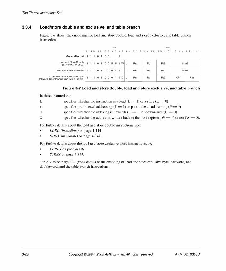
The Thumb Instruction Set
3.3.4 Load/store double and exclusive, and table branch
Figure 3-7 shows the encodings for load and store double, load and store exclusive, and table branch instructions.
Figure 3-7 Load and store double, load and store exclusive, and table branch
In these instructions:
L specifies whether the instruction is a load (L == 1) or a store (L == 0)
P specifies pre-indexed addressing (P == 1) or post-indexed addressing (P == 0)
U specifies whether the indexing is upwards (U == 1) or downwards (U == 0)
W specifies whether the address is written back to the base register (W == 1) or not (W == 0).
For further details about the load and store double instructions, see:
• LDRD (immediate) on page 4-114
• STRD (immediate) on page 4-347.
For further details about the load and store exclusive word instructions, see:
• LDREX on page 4-116
• STREX on page 4-349.
Table 3-35 on page 3-29 gives details of the encoding of load and store exclusive byte, halfword, and doubleword, and the table branch instructions.
"
�
� �
"
�
"
0���� �+����/���)�8� )��,'E@A"�""9
� � � � � � � � � � � " 2 ! # � � � � � "� � � � � � � � � � � " 2 ! # � � � � � "
� � ����
"� � � �
" ""� � � �
�
"
�
� � �
0���� �+����=4�)���*�
������������
" "
" "0���� �+����=4�)���*������B�),�����/���)������� ����)���� ��C
�
�
�
'
"
"
E
"
"�
"
7 0
0
0
�
�
�
��
��
��� ���
���
��
��
�� ?'���
3-28 Copyright © 2004, 2005 ARM Limited. All rights reserved. ARM DDI 0308D
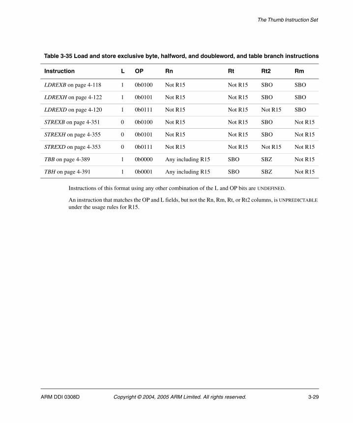
The Thumb Instruction Set
Instructions of this format using any other combination of the L and OP bits are UNDEFINED.
An instruction that matches the OP and L fields, but not the Rn, Rm, Rt, or Rt2 columns, is UNPREDICTABLE under the usage rules for R15.
Table 3-35 Load and store exclusive byte, halfword, and doubleword, and table branch instructions
Instruction L OP Rn Rt Rt2 Rm
LDREXB on page 4-118 1 0b0100 Not R15 Not R15 SBO SBO
LDREXH on page 4-122 1 0b0101 Not R15 Not R15 SBO SBO
LDREXD on page 4-120 1 0b0111 Not R15 Not R15 Not R15 SBO
STREXB on page 4-351 0 0b0100 Not R15 Not R15 SBO Not R15
STREXH on page 4-355 0 0b0101 Not R15 Not R15 SBO Not R15
STREXD on page 4-353 0 0b0111 Not R15 Not R15 Not R15 Not R15
TBB on page 4-389 1 0b0000 Any including R15 SBO SBZ Not R15
TBH on page 4-391 1 0b0001 Any including R15 SBO SBZ Not R15
ARM DDI 0308D Copyright © 2004, 2005 ARM Limited. All rights reserved. 3-29
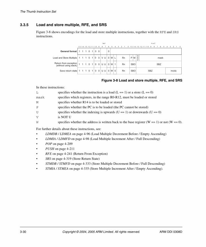
The Thumb Instruction Set
3.3.5 Load and store multiple, RFE, and SRS
Figure 3-8 shows encodings for the load and store multiple instructions, together with the RFE and SRS instructions.
Figure 3-8 Load and store multiple, RFE, and SRS
In these instructions:
L specifies whether the instruction is a load (L == 1) or a store (L == 0)
mask specifies which registers, in the range R0-R12, must be loaded or stored
M specifies whether R14 is to be loaded or stored
P specifies whether the PC is to be loaded (the PC cannot be stored)
U specifies whether the indexing is upwards (U == 1) or downwards (U == 0)
V is NOT U
W specifies whether the address is written back to the base register (W == 1) or not (W == 0).
For further details about these instructions, see:
• LDMDB / LDMEA on page 4-96 (Load Multiple Decrement Before / Empty Ascending)
• LDMIA / LDMFD on page 4-98 (Load Multiple Increment After / Full Descending)
• POP on page 4-209
• PUSH on page 4-211
• RFE on page 4-241 (Return From Exception)
• SRS on page 4-319 (Store Return State)
• STMDB / STMFD on page 4-333 (Store Multiple Decrement Before / Full Descending)
• STMIA / STMEA on page 4-335 (Store Multiple Increment After / Empty Ascending).
"
� �
""
�
"
0���� �+������)��$)�
� � � � � � � � � � � " 2 ! # � � � � � "� � � � � � � � � � � " 2 ! # � � � � � "
� � ����
"� � � �
" ""� � � �
" �
� � �
�
" �
" "
" "+�*������ �����
����� ,����4��$��� 8���������� -����19
"F 7 E 0 � ' �+�>
���1
"
"77 E
E77 �
� +�?
+�? ����+�>
+�>
������������
3-30 Copyright © 2004, 2005 ARM Limited. All rights reserved. ARM DDI 0308D
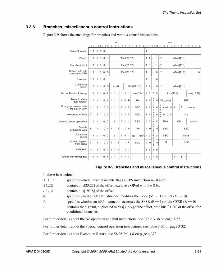
The Thumb Instruction Set
3.3.6 Branches, miscellaneous control instructions
Figure 3-9 shows the encodings for branches and various control instructions.
Figure 3-9 Branches and miscellaneous control instructions
In these instructions:
A, I, F specifies which interrupt disable flags a CPS instruction must alter
I1,I2 contain bits[23:22] of the offset, exclusive ORed with the S bit
J1,J2 contain bits[19:18] of the offset
M specifies whether a CPS instruction modifies the mode (M == 1) or not (M == 0)
R specifies whether an MRS instruction accesses the SPSR (R== 1) or the CPSR (R == 0)
S contains the sign bit, duplicated to bits[31:24] of the offset, or to bits[31:20] of the offset for conditional branches.
For further details about the No operation and hint instructions, see Table 3-36 on page 3-32.
For further details about the Special control operation instructions, see Table 3-37 on page 3-32.
For further details about Exception Return, see SUBS PC, LR on page 4-373.
"
"
�� � �
������������
� � � � � � � � � � � " 2 ! # � � � � � "� � � � � � � � � � � " 2 ! # � � � � � "
� � ����
��� ��
� � � �
"� � � �
+"� � � � �,,���%��5��&
"�� � �
�
��� ������)� 1���� -�����
�����*��
+ �
�
�
�
�,,���%��5��& �
�
G� G�
G� G�
�
"
"
"
�
(� ����� �)��� �� + �,,���%�!5��&
�,,���%��5�&
�,,���%��5�&
�,,���%��5�&�� � " "G� G�
"
"
�� � �
� � � �
"� � � �
"� � � �
"�� � �
�
"� � � �
� � � �
" � � �
" � � �
" � � �
" � � �
" � � �
" "
� " "+�>
�
� " "+�>
�
� " "+�>
+�?
� " "+�>
� " "+�>
+�?
�
�
"� "
" "
" �
� "
�
�
�
+�?
+�?
+�>
+�>
+�>
���
��
����+�>
,��)�H���1
���� � 6;
��� ���(�� -���G�*�
��*���������,�����-�����
(�� -�$�������������8������@A""�"9
��*�����-�����,���������
=4��$��� �����
"�� � � " � � � � " "+�?" � " "3��$������ ��� ��+�>
+�>
" �� �
��� ������)� 1 +"� � � � �,,���%��5��& � G� G�� �,,���%��5�&�
"
"� � � � " � � � � " "+�>
+�?�" � +�?+$����)�� ���)�$������ � �$���
"
�� � �
'���� � �)� ��������
"� � � � �� � � � " ""� � �+������� ����; �����$� ���%�5"& ���%��5�& ���%��5��&
?'
"
"� � � � �� � � � " "�� � �
��������
� � � �
8"98�9 8�9 8�9
ARM DDI 0308D Copyright © 2004, 2005 ARM Limited. All rights reserved. 3-31
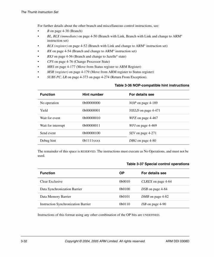
The Thumb Instruction Set
For further details about the other branch and miscellaneous control instructions, see:
• B on page 4-38 (Branch)
• BL, BLX (immediate) on page 4-50 (Branch with Link, Branch with Link and change to ARM® instruction set)
• BLX (register) on page 4-52 (Branch with Link and change to ARM® instruction set)
• BX on page 4-54 (Branch and change to ARM® instruction set)
• BXJ on page 4-56 (Branch and change to Jazelle® state)
• CPS on page 4-76 (Change Processor State)
• MRS on page 4-177 (Move from Status register to ARM Register)
• MSR (register) on page 4-179 (Move from ARM register to Status register)
• SUBS PC, LR on page 4-373 on page 4-274 (Return From Exception).
The remainder of this space is RESERVED. The instructions must execute as No Operations, and must not be used.
Instructions of this format using any other combination of the OP bits are UNDEFINED.
Table 3-36 NOP-compatible hint instructions
Function Hint number For details see
No operation 0b00000000 NOP on page 4-189
Yield 0b00000001 YIELD on page 4-471
Wait for event 0b00000010 WFE on page 4-467
Wait for interrupt 0b00000011 WFI on page 4-469
Send event 0b00000100 SEV on page 4-271
Debug hint 0b1111xxxx DBG on page 4-80
Table 3-37 Special control operations
Function OP For details see
Clear Exclusive 0b0010 CLREX on page 4-64
Data Synchronization Barrier 0b0100 DSB on page 4-84
Data Memory Barrier 0b0101 DMB on page 4-82
Instruction Synchronization Barrier 0b0110 ISB on page 4-90
3-32 Copyright © 2004, 2005 ARM Limited. All rights reserved. ARM DDI 0308D
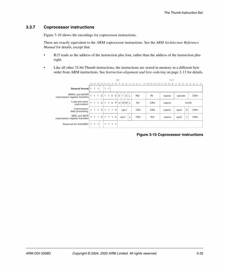
The Thumb Instruction Set
3.3.7 Coprocessor instructions
Figure 3-10 shows the encodings for coprocessor instructions.
These are exactly equivalent to the ARM coprocessor instructions. See the ARM Architecture Reference Manual for details, except that:
• R15 reads as the address of the instruction plus four, rather than the address of the instruction plus eight.
• Like all other 32-bit Thumb instructions, the instructions are stored in memory in a different byte order from ARM instructions. See Instruction alignment and byte ordering on page 2-13 for details.
Figure 3-10 Coprocessor instructions
������������
� � � � � � � � � � � " 2 ! # � � � � � "� � � � � � � � � � � " 2 ! # � � � � � "
� � ����
� � �
"(� � � � �
� �
'
"(� � � � �
(� � � � �
"
"�
(� � � � � "�
7
�$���$��
��$���0E3
0�
0
""
"
��$���$��
��$���
�
��� ��
�4,
(�
(�
(��
(��
���
�$���� (��
(��
(��
0���� ��������$��������
���(� ��(����$����������-�������� �,���
(�$������������$������� -
��(� ��(���$����������-�������� �,���
� � � � � � ������*��,���*+;�/
��$���
��$���
ARM DDI 0308D Copyright © 2004, 2005 ARM Limited. All rights reserved. 3-33
The Thumb Instruction Set
3.4 Conditional execution
Unlike ARM instructions, most Thumb instructions are unconditional. Before Thumb-2, the only conditional Thumb instruction was a 16-bit conditional branch instruction, B<cond>, with a branch range of –256 to +254 bytes.
Thumb-2 adds the following instructions:
• A 32-bit conditional branch, with a branch range of approximately ± 1MB, see B on page 4-38.
• A 16-bit If-Then instruction, IT. IT makes up to four following instructions conditional, see IT on page 4-92. The instructions that are made conditional by an IT instruction are called its IT block.
• A 16-bit Compare and Branch on Zero instruction, with a branch range of +4 to +130 bytes, see CBZ on page 4-60.
• A 16-bit Compare and Branch on Non-Zero instruction, with a branch range of +4 to +130 bytes, see CBNZ on page 4-58.
The condition codes that the conditional branch and IT instructions use are shown in Table 3-38 on page 3-35. They are the same as ARM condition codes.
The conditions of the instructions in an IT block are either all the same, or some of them are the inverse of the first condition.
3.4.1 Assembly language syntax
Although Thumb instructions are unconditional, all instructions that are made conditional by an IT instruction must be written with a condition. These conditions must match the conditions imposed by the IT instruction. For example, an ITTEE EQ instruction imposes the EQ condition on the first two following instructions, and the NE condition on the next two. Those four instructions must be written with EQ, EQ, NE and NE conditions respectively.
Some instructions are not allowed to be made conditional by an IT instruction, or are only allowed to be if they are the last instruction in the IT block.
The branch instruction encodings that include a condition field are not allowed to be made conditional by an IT instruction. If the assembler syntax indicates a conditional branch that correctly matches a preceding IT instruction, it must be assembled using a branch instruction encoding that does not include a condition field.
3-34 Copyright © 2004, 2005 ARM Limited. All rights reserved. ARM DDI 0308D
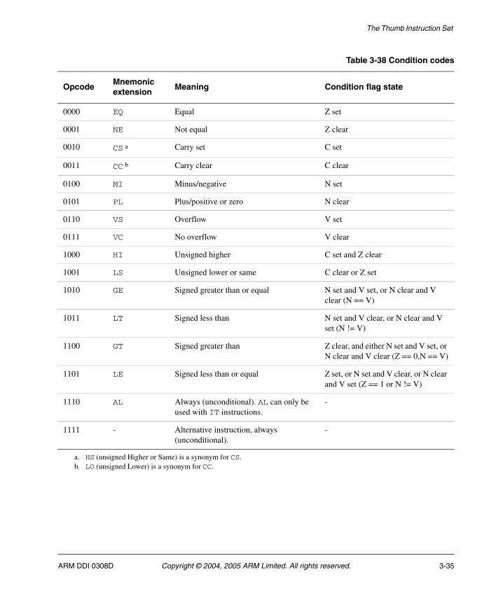
The Thumb Instruction Set
Table 3-38 Condition codes
OpcodeMnemonic extension
Meaning Condition flag state
0000 EQ Equal Z set
0001 NE Not equal Z clear
0010 CS a Carry set C set
0011 CC b Carry clear C clear
0100 MI Minus/negative N set
0101 PL Plus/positive or zero N clear
0110 VS Overflow V set
0111 VC No overflow V clear
1000 HI Unsigned higher C set and Z clear
1001 LS Unsigned lower or same C clear or Z set
1010 GE Signed greater than or equal N set and V set, or N clear and V clear (N == V)
1011 LT Signed less than N set and V clear, or N clear and V set (N != V)
1100 GT Signed greater than Z clear, and either N set and V set, or N clear and V clear (Z == 0,N == V)
1101 LE Signed less than or equal Z set, or N set and V clear, or N clear and V set (Z == 1 or N != V)
1110 AL Always (unconditional). AL can only be used with IT instructions.
-
1111 - Alternative instruction, always (unconditional).
-
a. HS (unsigned Higher or Same) is a synonym for CS.b. LO (unsigned Lower) is a synonym for CC.
ARM DDI 0308D Copyright © 2004, 2005 ARM Limited. All rights reserved. 3-35
The Thumb Instruction Set
3.5 UNDEFINED and UNPREDICTABLE instruction set space
An attempt to execute an unallocated instruction results in either:
• Unpredictable behavior. The instruction is described as UNPREDICTABLE.
• An Undefined Instruction exception. The instruction is described as UNDEFINED.
This section describes the general rules that determine whether an unallocated instruction in the Thumb instruction set space is UNDEFINED or UNPREDICTABLE.
Note See Usage of 0b1111 as a register specifier in 32-bit encodings on page 3-38 and Usage of 0b1101 as a register specifier on page 3-41 for additional information on UNPREDICTABLE behavior associated with the usage models of R13 and R15.
3.5.1 16-bit instruction set space
Instruction bits[15:6] are used for decode.
Instructions where bits[15:10] == 0b010001 are special data processing operations. Unallocated instructions in this space are UNPREDICTABLE. In ARMv6 this is where bits[9:6] == 0b0000 or 0b0100. In ARMv7 this is where bits[9:6] == 0b0100.
All other unallocated instructions are UNDEFINED.
Permanently undefined space
The part of the instruction set space where bits[15:8] == 0b11011110 is architecturally undefined. This space is available for instruction emulation, or for other purposes where software wants to force an Undefined Instruction exception to occur.
3.5.2 32-bit instruction set space
The following general rules apply to all 32-bit Thumb instructions:
• The hw1[15:11] bit-field is always in the range 0b11101 to 0b11111 inclusive.
• Instruction classes are determined by hw1[15:8,6] and hw2[15]. For details see Figure 3-3 on page 3-12.
• Instructions are made up of three types of bit field:
— opcode fields
— register specifiers
— immediate fields specifying shifts or immediate values.
• Opcode fields are defined in Figure 3-4 on page 3-13 to Figure 3-10 on page 3-33 inclusive.
3-36 Copyright © 2004, 2005 ARM Limited. All rights reserved. ARM DDI 0308D
The Thumb Instruction Set
An instruction is UNDEFINED if:
• it corresponds to any Undefined or Reserved encoding in Figure 3-4 on page 3-13 to Figure 3-10 on page 3-33 inclusive
• it corresponds to an opcode bit pattern that is missing from the tables associated with the figures (that is, Table 3-21 on page 3-14 to Table 3-37 on page 3-32 inclusive), or noted in the subsection text
• it is declared as UNDEFINED within an instruction description.
An instruction is UNPREDICTABLE if:
• a register specifier is 0b1111 or 0b1101 and the instruction does not specifically describe this case
• an SBZ bit or multi-bit field is not zero or all zeros
• an SBO bit or multi-bit field is not one or all ones
• it is declared as UNPREDICTABLE within an instruction description.
ARM DDI 0308D Copyright © 2004, 2005 ARM Limited. All rights reserved. 3-37
The Thumb Instruction Set
3.6 Usage of 0b1111 as a register specifier in 32-bit encodings
In ARM instructions, a value of 0b1111 in a register specification normally specifies the PC. This usage is not normally permitted in Thumb-2.
When a value of 0b1111 is permitted, a variety of meanings is possible. For register reads, these meanings are:
• Read the PC value, that is, the address of the current instruction + 4. The base register of the table branch instructions TBB and TBH is allowed to be the PC. This allows branch tables to be placed in memory immediately after the instruction. (Some instructions read the PC value implicitly, without the use of a register specifier, for example the conditional branch instruction B<cond>.)
Note Use of the PC as the base register in the STC instruction is deprecated in ARMv7.
• Read the word-aligned PC value, that is, the address of the current instruction + 4, with bits[1:0] forced to zero. The base register of LDC, STC, LDR, LDRB, LDRD (pre-indexed, no writeback), LDRH, LDRSB, and LDRSH instructions are allowed to be the word-aligned PC. This allows PC-relative data addressing. In addition, the ADDW and SUBW instructions allow their source registers to be 0b1111 for the same purpose.
• Read zero. This is done when one instruction is a special case of another, more general instruction, but with one operand zero. In these cases, the instructions are listed on separate pages, with Encoding notes for each instruction cross-referencing the other. This is the case for the following instructions:
BFC special case of BFI
MOV special case of ORR
MUL special case of MLA
MVN special case of ORN
SMMUL special case of SMMLA
SMUAD special case of SMLAD
SMUL<x><y> special case of SMLA<x><y>
SMULW<y> special case of SMLAW<y>
SMUSD special case of SMLSD
SXTB special case of SXTAB
SXTB16 special case of SXTAB16
SXTH special case of SXTAH
USAD8 special case of USADA8
UXTB special case of UXTAB
UXTB16 special case of UXTAB16
UXTH special case of UXTAH.
3-38 Copyright © 2004, 2005 ARM Limited. All rights reserved. ARM DDI 0308D
The Thumb Instruction Set
For register writes, these meanings are:
• The PC can be specified as the destination register of an LDR instruction. This is done by encoding Rt as 0b1111. The loaded value is treated as an address, and the effect of execution is a branch to that address. Bit[0] of the loaded value selects whether to execute ARM or Thumb instructions after the branch.
Some other instructions write the PC in similar ways, either implicitly (for example, B<cond>) or by using a register mask rather than a register specifier (LDM). The address to branch to can be a loaded value (for example, RFE), a register value (for example, BX), or the result of a calculation (for example, TBB or TBH). The ARM or Thumb instruction set selection can be similar to the LDR case (LDM or BX), unconditional (for example, the revised 32-bit form of BLX), unchanged (for example, B<cond>), or set from the (J,T) bits of the SPSR (RFE and SUBS PC,LR,#imm8).
• Discard the result of a calculation. This is done when one instruction is a special case of another, more general instruction, but with the result discarded. In these cases, the instructions are listed on separate pages, with Encoding notes for each instruction cross-referencing the other.
This is the case for the following instructions:
CMN special case of ADDS
CMP special case of SUBS
TEQ special case of EORS
TST special case of ANDS.
• If the destination register specifier of an LDRB, LDRH, LDRSB, or LDRSH instruction is 0b1111, the instruction is a memory hint instead of a load operation.
This is the case for the following instructions:
PLD uses LDRB encoding
PLI uses LDRSB encoding.
The unallocated memory hint instruction encodings (LDRH and LDRSH encodings) execute as NOP, instead of being UNDEFINED or UNPREDICTABLE like most other unallocated instruction encodings. See Memory hints on page 4-14 for further details.
• If the destination register specifier of an MRC instruction is 0b1111, bits[31:28] of the value transferred from the coprocessor are written to the (N,Z,C,V) flags in the CPSR, and bits[27:0] are discarded.
3.6.1 ARM-Thumb interworking
Thumb interworking uses bit[0] on a write to the PC to determine the CPSR T bit. For 16-bit instructions, interworking behavior is as follows:
• ADD (4) and MOV (3) branch within Thumb state ignoring bit[0].
• B (unconditional) and B (conditional) branch without interworking
• BKPT and SVC (SWI) cause an exception, the exception mechanism responsible for any state transition, and are not considered as interworking instructions.
ARM DDI 0308D Copyright © 2004, 2005 ARM Limited. All rights reserved. 3-39
The Thumb Instruction Set
• BLX(2) and BX interwork on the value in Rm
For 32-bit instructions, interworking behavior is as follows:
• B (unconditional) and B (conditional) branch without interworking
• BL and BLX branch to Thumb and ARM state respectively based on the instruction encoding, not due to bit[0] of the value written to the PC. They are therefore related to interworking instructions, rather than being interworking instructions themselves.
• LDM and LDR support interworking using the value written to the PC.
• TBB and TBH branch without interworking.
3-40 Copyright © 2004, 2005 ARM Limited. All rights reserved. ARM DDI 0308D
The Thumb Instruction Set
3.7 Usage of 0b1101 as a register specifier
R13 is redefined in Thumb-2 so that its usage model is strongly linked to that of a stack pointer. This change aligns R13 with the ARM Procedure Call Standard (PCS), the architecture usage model defined by the SRS and RFE 32-bit instructions, and the PUSH and POP instructions in the 16-bit instruction set.
In the 32-bit Thumb instruction set, if you use R13 as a general purpose register beyond the architecturally defined constraints described in this section, the results are UNPREDICTABLE. For the ARM ISA, support of R13, other than that described for Thumb-2, is deprecated.
The changes to R13 are described in:
• R13[1:0] definition
• Thumb-2 ISA support for R13.
See also Thumb-2 16-bit ISA support for R13 on page 3-42.
3.7.1 R13[1:0] definition
Bits[1:0] of R13 adopt a SBZP (Should Be Zero or Preserved) write policy, that is, it is permitted to write zeros or values read from them. Writing anything else to bits[1:0] results in UNPREDICTABLE values. Reading bits[1:0] returns the value written earlier, unless the value read is UNPREDICTABLE.
This definition means that R13 can be set to a word-aligned address. This supports ADD/SUB R13,R13,#4 without either a requirement that R13[1:0] must always read as zero or a need to use ADD/SUB Rt,R13,#4; BIC R13,Rt,#3 to force word-alignment of the write to R13.
3.7.2 Thumb-2 ISA support for R13
R13 instruction support is restricted to the following:
• R13 as the source or destination register of a MOV instruction. Only register <=> register (no shift) transfers are supported, with no flag setting:
MOV SP,RmMOV Rn,SP
• Adjusting R13 up or down by a multiple of its alignment:
ADD{W} SP,SP,#N ; For N a multiple of 4SUB{W} SP,SP,#N ; For N a multiple of 4ADD SP,SP,Rm,LSL #shft ; For shft=0,1,2,3SUB SP,SP,Rm,LSL #shft ; For shft=0,1,2,3
• R13 as a base register (Rn) of any load or store instruction. This supports SP-based addressing for load, store, or memory hint instructions, with positive or negative offsets, with and without writeback.
• R13 as the first operand (Rn) in any ADD{S}, ADDW, CMN, CMP, SUB{S}, or SUBW instruction. The add/subtract instructions support SP-based address generation, with the address going into a general-purpose register. CMN and CMP are useful for stack checking in some circumstances.
• R13 as the transferred register (Rt) in any LDR or STR instruction.
ARM DDI 0308D Copyright © 2004, 2005 ARM Limited. All rights reserved. 3-41
The Thumb Instruction Set
3.7.3 Thumb-2 16-bit ISA support for R13
For 16-bit data processing instructions that affect high registers, R13 can only be used as described in Thumb-2 ISA support for R13 on page 3-41. Any other use is deprecated. This affects the high register forms of CMP and ADD, where the use of R13 as Rm is deprecated. For more information about high registers, see the ARM Architecture Reference Manual.
3-42 Copyright © 2004, 2005 ARM Limited. All rights reserved. ARM DDI 0308D
The Thumb Instruction Set
3.8 Thumb-2 and VFP support
VFP instructions are coprocessor instructions, where the coprocessor number is either 10 or 11.
VFP instructions are supported in Thumb-2 as unconditional versions of their ARM encodings. hw1[15:0] corresponds to the ARM instruction bits[31:16] and hw2[15:0] corresponds to the ARM instruction bits[15:0].
All VFP instructions can be made conditional in Thumb-2 using the IT instruction (see IT on page 4-92).
VFP instructions that follow the MCR, MRC, MRRC, MCRR, LDC, STC and CDP formats are identical to the unconditional form of the ARM instructions, that is hw1[15:12] == 0b1110.
VFP instructions that follow the MCR2, MRC2, MRRC2, MCRR2, LDC2, STC2 and CDP2 formats are identical to the ARM instructions, that is, hw1[15:12] == 0b1111.
The VFP load and store multiple instructions, LDC (2) and STC (2), are UNPREDICTABLE when the base register is R15.
Note This is different from their equivalent ARM instruction. This is because the PC value used (CurrentInstructionAddress + 4) does not allow for a branch around a literal pool.
For more information about VFP, see the ARM Architecture Reference Manual.
ARM DDI 0308D Copyright © 2004, 2005 ARM Limited. All rights reserved. 3-43

The Thumb Instruction Set
3-44 Copyright © 2004, 2005 ARM Limited. All rights reserved. ARM DDI 0308D
Chapter 4 Thumb Instructions
This chapter describes each Thumb®-2 32-bit instruction. It contains the following sections:
• Format of instruction descriptions on page 4-2
• Immediate constants on page 4-8
• Constant shifts applied to a register on page 4-10
• Memory accesses on page 4-13
• Memory hints on page 4-14
• Alphabetical list of Thumb instructions on page 4-15.
ARM DDI 0308D Copyright © 2004, 2005 ARM Limited. All rights reserved. 4-1
Thumb Instructions
4.1 Format of instruction descriptions
The instruction descriptions in the alphabetical lists of instructions in Alphabetical list of Thumb instructions on page 4-15 and Alphabetical list of new ARM instructions on page 5-2 normally use the following format:
• instruction section title
• introduction to the instruction
• instruction encoding(s)
• architecture version information
• assembler syntax
• pseudo-code describing how the instruction operates
• exception information
• notes (where applicable).
Each of these items is described in more detail in the following subsections.
A few instruction descriptions describe alternative mnemonics for other instructions and use an abbreviated and modified version of this format.
4.1.1 Instruction section title
The instruction section title gives the base mnemonic for the instructions described in the section. When one mnemonic has multiple forms described in separate instruction sections, this is followed by a short description of the form in parentheses. The most common use of this is to distinguish between forms of an instruction in which one of the operands is an immediate value and forms in which it is a register.
Parenthesized text is also used to document the former mnemonic in some cases where a mnemonic has been replaced entirely by another mnemonic in the new assembler syntax.
4.1.2 Introduction to the instruction
The instruction section title is followed by text that briefly describes the main features of the instruction. This description is not necessarily complete and is not definitive. If there is any conflict between it and the more detailed information that follows, the latter takes priority.
4-2 Copyright © 2004, 2005 ARM Limited. All rights reserved. ARM DDI 0308D
Thumb Instructions
4.1.3 Instruction encodings
The Encodings subsection contains a list of one or more instruction encodings. For reference purposes, each instruction encoding is labelled, T1, T2, T3... (for Thumb instructions) or A1, A2, A3... (for ARM instructions).
Each instruction encoding description consists of:
• An assembly syntax that ensures that the assembler selects the encoding in preference to any other encoding. In some cases, multiple syntaxes are given. The correct one to use is sometimes indicated by annotations to the syntax, such as Inside IT block and Outside IT block. In other cases, the correct one to use can be determined by looking at the assembler syntax description and using it to determine which syntax corresponds to the instruction being disassembled.
There is usually more than one syntax that ensures re-assembly to any particular encoding, and the exact set of syntaxes that do so usually depends on the register numbers, immediate constants and other operands to the instruction. For example, when assembling to the Thumb instruction set, the syntax AND R0,R0,R8 ensures selection of a 32-bit encoding but AND R0,R0,R1 selects a 16-bit encoding.
The assembly syntax documented for the encoding is chosen to be the simplest one that ensures selection of that encoding for all operand combinations supported by that encoding. This often means that it includes elements that are only necessary for a small subset of operand combinations. For example, the assembler syntax documented for the 32-bit Thumb AND (register) encoding includes the .W qualifier to ensure that the 32-bit encoding is selected even for the small proportion of operand combinations for which the 16-bit encoding is also available.
The assembly syntax given for an encoding is therefore a suitable one for a disassembler to disassemble that encoding to. However, disassemblers may wish to use simpler syntaxes when they are suitable for the operand combination, in order to produce more readable disassembled code.
• An encoding diagram. This is half-width for 16-bit Thumb encodings and full-width for 32-bit Thumb and ARM encodings. The 32-bit Thumb encodings use a double vertical line between the two halfwords of the instruction to distinguish them from ARM encodings and to act as a reminder that 32-bit Thumb encodings use the byte order of a sequence of two halfwords rather than of a word, as described in Instruction alignment and byte ordering on page 2-13.
• Encoding-specific pseudo-code. This is pseudo-code that translates the encoding-specific instruction fields into inputs to the encoding-independent pseudo-code in the later Operation subsection, and that picks out any special cases in the encoding. For a detailed description of the pseudo-code used and of the relationship between the encoding diagram, the encoding-specific pseudo-code and the encoding-independent pseudo-code, see Appendix A Pseudo-code definition.
4.1.4 Architecture version information
The Architecture versions subsection contains information about which architecture versions include the instruction. This often differs between encodings.
ARM DDI 0308D Copyright © 2004, 2005 ARM Limited. All rights reserved. 4-3
Thumb Instructions
4.1.5 Assembler syntax
The Assembly syntax subsection describes the standard UAL syntax for the instruction.
Each syntax description consists of the following elements:
• One or more syntax prototype lines written in a typewriter font, using the conventions described in Assembler syntax prototype line conventions on page 4-5. Each prototype line documents the mnemonic and (where appropriate) operand parts of a full line of assembler code. When there is more than one such line, each prototype line is annotated to indicate required results of the encoding-specific pseudo-code. For each instruction encoding, this information can be used to determine whether any instructions matching that encoding are available when assembling that syntax, and if so, which ones.
• The line where: followed by descriptions of all of the variable or optional fields of the prototype syntax line.
Some syntax fields are standardized across all or most instructions. These fields are described in Standard assembler syntax fields on page 4-6.
By default, syntax fields that specify registers (such as <Rd>, <Rn>, or <Rt>) are permitted to be any of R0-R12 or LR in Thumb instructions, and any of R0-R12, SP or LR in ARM instructions. These require that the encoding-specific pseudo-code should set the corresponding integer variable (such as d, n, or t) to the corresponding register number (0-12 for R0-R12, 13 for SP, 14 for LR). This can normally be done by setting the corresponding bitfield in the instruction (named Rd, Rn, Rt...) to the binary encoding of that number. In the case of 16-bit Thumb encodings, this bitfield is normally of length 3 and so the encoding is only available when one of R0-R7 was specified in the assembler syntax. It is also common for such encodings to use a bitfield name such as Rdn. This indicates that the encoding is only available if <Rd> and <Rn> specify the same register, and that the register number of that register is encoded in the bitfield if they do.
The description of a syntax field that specifies a register sometimes extends or restricts the permitted range of registers or document other differences from the default rules for such fields. Typical extensions are to allow the use of the SP in Thumb instructions and to allow the use of the PC (using register number 15).
• Where appropriate, text that briefly describes changes from the pre-UAL ARM assembler syntax. Where this is present, it usually consists of an alternative pre-UAL form of the assembler mnemonic. The pre-UAL ARM assembler syntax does not conflict with UAL, and support for it is a recommended optional extension to UAL, to allow the assembly of pre-UAL ARM assembler source files.
Note The pre-UAL Thumb assembler syntax is incompatible with UAL and is not documented in the instruction sections.
4-4 Copyright © 2004, 2005 ARM Limited. All rights reserved. ARM DDI 0308D
Thumb Instructions
Assembler syntax prototype line conventions
The following conventions are used in assembler syntax prototype lines and their subfields:
< > Any item bracketed by < and > is a short description of a type of value to be supplied by the user in that position. A longer description of the item is normally supplied by subsequent text. Such items often correspond to a similarly named field in an encoding diagram for an instruction. When the correspondence simply requires the binary encoding of an integer value or register number to be substituted into the instruction encoding, it is not described explicitly. For example, if the assembler syntax for an ARM instruction contains an item <Rn> and the instruction encoding diagram contains a 4-bit field named Rn, the number of the register specified in the assembler syntax is encoded in binary in the instruction field.
If the correspondence between the assembler syntax item and the instruction encoding is more complex than simple binary encoding of an integer or register number, the item description indicates how it is encoded.
{ } Any item bracketed by { and } is optional. A description of the item and of how its presence or absence is encoded in the instruction is normally supplied by subsequent text.
| This indicates an alternative character string. For example, LDM|STM is either LDM or STM.
spaces Single spaces are used for clarity, to separate items. When a space is obligatory in the assembler syntax, two or more consecutive spaces are used.
+/- This indicates an optional + or - sign. If neither is coded, + is assumed.
* When used in a combination like <immed_8> * 4, this describes an immediate value which must be a specified multiple of a value taken from a numeric range. In this instance, the numeric range is 0 to 255 (the set of values that can be represented as an 8-bit immediate) and the specified multiple is 4, so the value described must be a multiple of 4 in the range 4*0 = 0 to 4*255 = 1020.
All other characters must be encoded precisely as they appear in the assembler syntax. Apart from { and }, the special characters described above do not appear in the basic forms of assembler instructions documented in this manual. The { and } characters need to be encoded in a few places as part of a variable item. When this happens, the long description of the variable item indicates how they must be used.
ARM DDI 0308D Copyright © 2004, 2005 ARM Limited. All rights reserved. 4-5
Thumb Instructions
Standard assembler syntax fields
The following assembler syntax fields are standard across all or most instructions:
<c> Is an optional field. It specifies the condition under which the instruction is executed. If <c> is omitted, it defaults to always (AL). For details see Conditional execution on page 3-34.
<q> Specifies optional assembler qualifiers on the instruction. The following qualifiers are defined:
.N Meaning narrow, specifies that the assembler must select a 16-bit encoding for the instruction. If this is not possible, an assembler error is produced.
.W Meaning wide, specifies that the assembler must select a 32-bit encoding for the instruction. If this is not possible, an assembler error is produced.
If neither .W nor .N is specified, the assembler can select either 16-bit or 32-bit encodings. If both are available, it must select a 16-bit encoding. In a few cases, more than one encoding of the same length can be available for an instruction. The rules for selecting between such encodings are instruction-specific and are part of the instruction description.
Note When assembling to ARM, the .N qualifier will produce an assembler error and the .W
qualifier has no effect, because all ARM instructions have length 32 bits.
4.1.6 Pseudo-code describing how the instruction operates
The Operation subsection contains encoding-independent pseudo-code that describes the main operation of the instruction. For a detailed description of the pseudo-code used and of the relationship between the encoding diagram, the encoding-specific pseudo-code and the encoding-independent pseudo-code, see Appendix A Pseudo-code definition.
4-6 Copyright © 2004, 2005 ARM Limited. All rights reserved. ARM DDI 0308D
Thumb Instructions
4.1.7 Exception information
The Exceptions subsection contains a list of the exceptional conditions that can be caused by execution of the instruction.
Processor exceptions are listed as follows:
• Resets and interrupts (both IRQs and FIQs) are not listed. They can occur before or after the execution of any instruction, and in some cases during the execution of an instruction, but they are not in general caused by the instruction concerned.
• Prefetch Abort exceptions are normally caused by a memory abort when an instruction is fetched, followed by an attempt to execute that instruction. This can happen for any instruction, but is caused by the aborted attempt to fetch the instruction rather than by the instruction itself, and so is not listed. A special case is the BKPT instruction, which is defined as causing a Prefetch Abort exception in some circumstances.
• Data Abort exceptions are listed for all instructions that perform data memory accesses.
• Undefined Instruction exceptions are listed when they are part of the effects of a defined instruction. For example, all coprocessor instructions are defined to produce the Undefined Instruction exception if not accepted by their coprocessor. Undefined Instruction exceptions caused by the execution of an UNDEFINED instruction are not listed, even when the UNDEFINED instruction is a special case of one or more of the encodings of the instruction. Such special cases are instead indicated in the encoding-specific pseudo-code for the encoding.
• Supervisor Call and Secure Monitor Call exceptions are listed for the SVC and SMC instructions respectively. Supervisor Call exceptions and the SVC instruction were formerly called Software Interrupt exceptions and the SWI instruction. Secure Monitor Call exceptions and the SMC instruction were formerly called Secure Monitor interrupts and the SMI instruction.
4.1.8 Notes
Where appropriate, additional notes about the instruction appear under further subheadings.
Note Information that was documented in notes in previous versions of the ARM Architecture Reference Manual and its supplements has often been moved elsewhere in this supplement. For example, operand restrictions on the values of bitfields in an instruction encoding are now normally documented in the encoding-specific pseudo-code for that encoding.
ARM DDI 0308D Copyright © 2004, 2005 ARM Limited. All rights reserved. 4-7
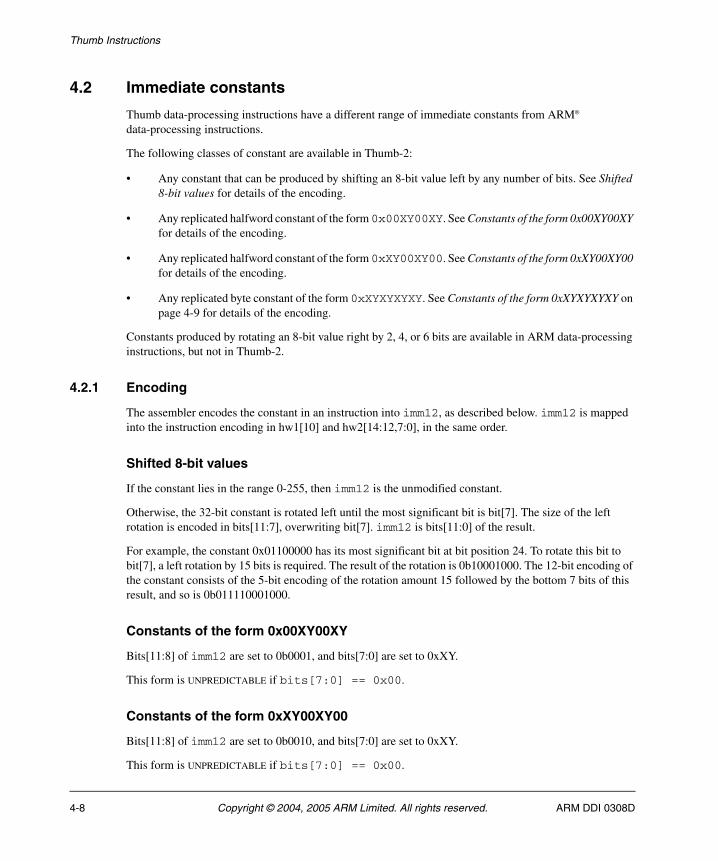
Thumb Instructions
4.2 Immediate constants
Thumb data-processing instructions have a different range of immediate constants from ARM® data-processing instructions.
The following classes of constant are available in Thumb-2:
• Any constant that can be produced by shifting an 8-bit value left by any number of bits. See Shifted 8-bit values for details of the encoding.
• Any replicated halfword constant of the form 0x00XY00XY. See Constants of the form 0x00XY00XY for details of the encoding.
• Any replicated halfword constant of the form 0xXY00XY00. See Constants of the form 0xXY00XY00 for details of the encoding.
• Any replicated byte constant of the form 0xXYXYXYXY. See Constants of the form 0xXYXYXYXY on page 4-9 for details of the encoding.
Constants produced by rotating an 8-bit value right by 2, 4, or 6 bits are available in ARM data-processing instructions, but not in Thumb-2.
4.2.1 Encoding
The assembler encodes the constant in an instruction into imm12, as described below. imm12 is mapped into the instruction encoding in hw1[10] and hw2[14:12,7:0], in the same order.
Shifted 8-bit values
If the constant lies in the range 0-255, then imm12 is the unmodified constant.
Otherwise, the 32-bit constant is rotated left until the most significant bit is bit[7]. The size of the left rotation is encoded in bits[11:7], overwriting bit[7]. imm12 is bits[11:0] of the result.
For example, the constant 0x01100000 has its most significant bit at bit position 24. To rotate this bit to bit[7], a left rotation by 15 bits is required. The result of the rotation is 0b10001000. The 12-bit encoding of the constant consists of the 5-bit encoding of the rotation amount 15 followed by the bottom 7 bits of this result, and so is 0b011110001000.
Constants of the form 0x00XY00XY
Bits[11:8] of imm12 are set to 0b0001, and bits[7:0] are set to 0xXY.
This form is UNPREDICTABLE if bits[7:0] == 0x00.
Constants of the form 0xXY00XY00
Bits[11:8] of imm12 are set to 0b0010, and bits[7:0] are set to 0xXY.
This form is UNPREDICTABLE if bits[7:0] == 0x00.
4-8 Copyright © 2004, 2005 ARM Limited. All rights reserved. ARM DDI 0308D

Thumb Instructions
Constants of the form 0xXYXYXYXY
Bits[11:8] of imm12 are set to 0b0011, and bits[7:0] are set to 0xXY.
This form is UNPREDICTABLE if bits[7:0] == 0x00.
4.2.2 Operation
// ThumbExpandImm()// ----------------
bits(32) ThumbExpandImm(bits(12) imm12)(imm32, -) = ThumbExpandImmWithC(imm12);return imm12;
// ThumbExpandImmWithC()// ---------------------
(bits(32), bit) ThumbExpandImmWithC(bits(12) imm12)
if imm12<11:10> == '00' then
case imm12<9:8> of when '00' imm32 = ZeroExtend(imm12<7:0>, 32); when '01' if imm12<7:0> == '00000000' then UNPREDICTABLE; imm32 = '00000000' : imm12<7:0> : '00000000' : imm12<7:0>; when '10' if imm12<7:0> == '00000000' then UNPREDICTABLE; imm32 = imm12<7:0> : '00000000' : imm12<7:0> : '00000000'; when '11' if imm12<7:0> == '00000000' then UNPREDICTABLE; imm32 = imm12<7:0> : imm12<7:0> : imm12<7:0> : imm12<7:0>;
carry_out = APSR.C;
else
unrotated_value = ZeroExtend('1':imm12<6:0>, 32); (imm32, carry_out) = ROR_C(unrotated_value, UInt(imm12<11:7>));
return (imm32, carry_out);
ARM DDI 0308D Copyright © 2004, 2005 ARM Limited. All rights reserved. 4-9
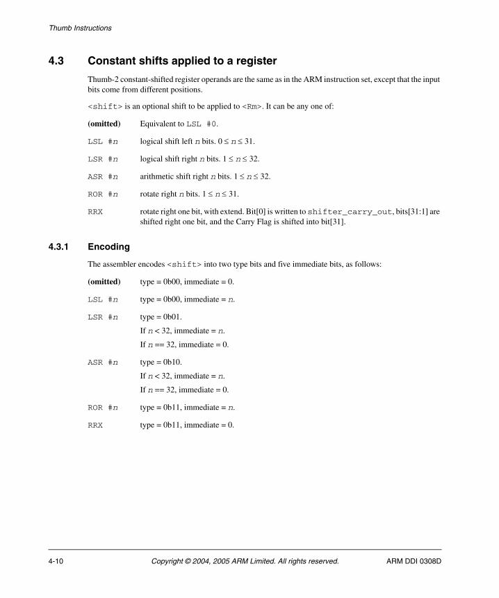
Thumb Instructions
4.3 Constant shifts applied to a register
Thumb-2 constant-shifted register operands are the same as in the ARM instruction set, except that the input bits come from different positions.
<shift> is an optional shift to be applied to <Rm>. It can be any one of:
(omitted) Equivalent to LSL #0.
LSL #n logical shift left n bits. 0 ≤ n ≤ 31.
LSR #n logical shift right n bits. 1 ≤ n ≤ 32.
ASR #n arithmetic shift right n bits. 1 ≤ n ≤ 32.
ROR #n rotate right n bits. 1 ≤ n ≤ 31.
RRX rotate right one bit, with extend. Bit[0] is written to shifter_carry_out, bits[31:1] are shifted right one bit, and the Carry Flag is shifted into bit[31].
4.3.1 Encoding
The assembler encodes <shift> into two type bits and five immediate bits, as follows:
(omitted) type = 0b00, immediate = 0.
LSL #n type = 0b00, immediate = n.
LSR #n type = 0b01.
If n < 32, immediate = n.
If n == 32, immediate = 0.
ASR #n type = 0b10.
If n < 32, immediate = n.
If n == 32, immediate = 0.
ROR #n type = 0b11, immediate = n.
RRX type = 0b11, immediate = 0.
4-10 Copyright © 2004, 2005 ARM Limited. All rights reserved. ARM DDI 0308D
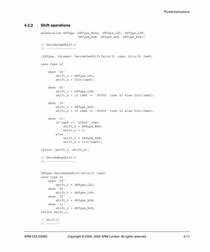
Thumb Instructions
4.3.2 Shift operations
enumeration SRType (SRType_None, SRType_LSL, SRType_LSR, SRType_ASR, SRType_ROR, SRType_RRX);
// DecodeImmShift()// ----------------
(SRType, integer) DecodeImmShift(bits(2) type, bits(5) imm5)
case type of
when '00' shift_t = SRType_LSL; shift_n = UInt(imm5);
when '01' shift_t = SRType_LSR; shift_n = if imm5 == '00000' then 32 else UInt(imm5);
when '10' shift_t = SRType_ASR; shift_n = if imm5 == '00000' then 32 else UInt(imm5);
when '11' if imm5 == '00000' then shift_t = SRType_RRX; shift_n = 1; else shift_t = SRType_ROR; shift_n = UInt(imm5);
return (shift_t, shift_n);
// DecodeRegShift()// ----------------
SRType DecodeRegShift(bits(2) type)case type of when '00' shift_t = SRType_LSL; when '01' shift_t = SRType_LSR; when '10' shift_t = SRType_ASR; when '11' shift_t = SRType_ROR;return shift_t;
// Shift()// -------
ARM DDI 0308D Copyright © 2004, 2005 ARM Limited. All rights reserved. 4-11
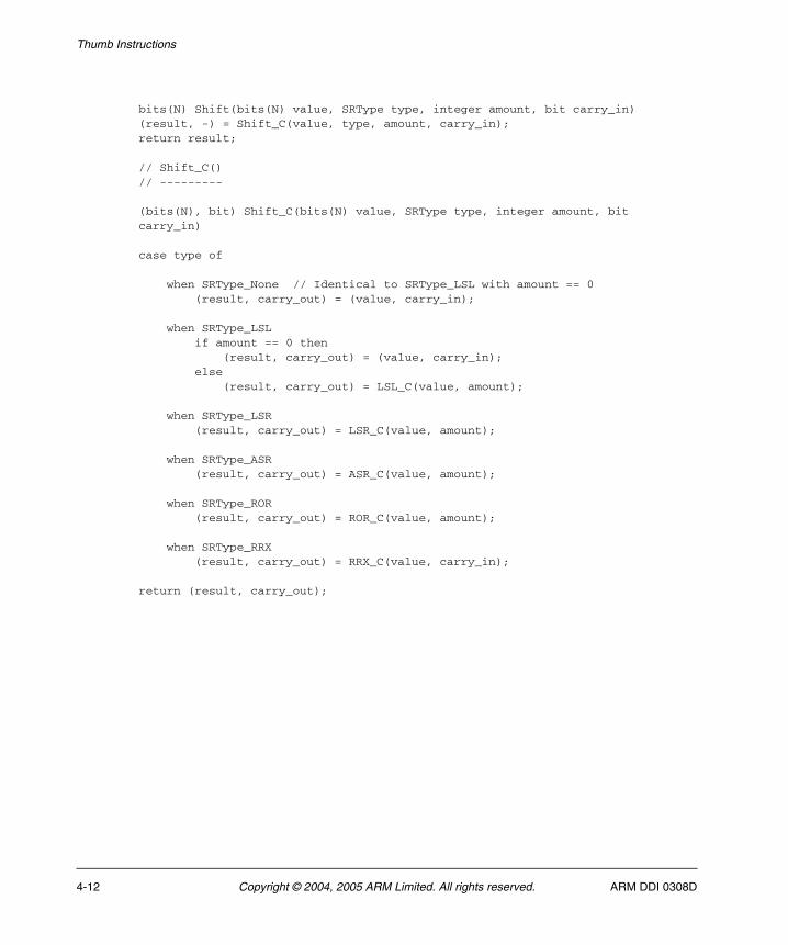
Thumb Instructions
bits(N) Shift(bits(N) value, SRType type, integer amount, bit carry_in)(result, -) = Shift_C(value, type, amount, carry_in);return result;
// Shift_C()// ---------
(bits(N), bit) Shift_C(bits(N) value, SRType type, integer amount, bit carry_in)
case type of
when SRType_None // Identical to SRType_LSL with amount == 0 (result, carry_out) = (value, carry_in);
when SRType_LSL if amount == 0 then (result, carry_out) = (value, carry_in); else (result, carry_out) = LSL_C(value, amount);
when SRType_LSR (result, carry_out) = LSR_C(value, amount);
when SRType_ASR (result, carry_out) = ASR_C(value, amount);
when SRType_ROR (result, carry_out) = ROR_C(value, amount);
when SRType_RRX (result, carry_out) = RRX_C(value, carry_in);
return (result, carry_out);
4-12 Copyright © 2004, 2005 ARM Limited. All rights reserved. ARM DDI 0308D
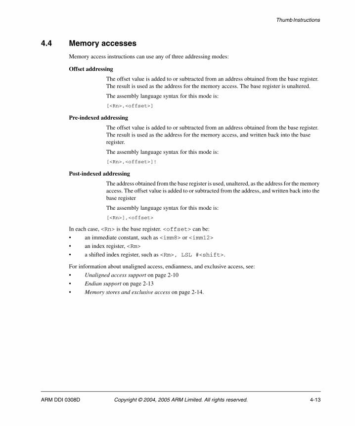
Thumb Instructions
4.4 Memory accesses
Memory access instructions can use any of three addressing modes:
Offset addressing
The offset value is added to or subtracted from an address obtained from the base register. The result is used as the address for the memory access. The base register is unaltered.
The assembly language syntax for this mode is:
[<Rn>,<offset>]
Pre-indexed addressing
The offset value is added to or subtracted from an address obtained from the base register. The result is used as the address for the memory access, and written back into the base register.
The assembly language syntax for this mode is:
[<Rn>,<offset>]!
Post-indexed addressing
The address obtained from the base register is used, unaltered, as the address for the memory access. The offset value is added to or subtracted from the address, and written back into the base register
The assembly language syntax for this mode is:
[<Rn>],<offset>
In each case, <Rn> is the base register. <offset> can be:
• an immediate constant, such as <imm8> or <imm12>
• an index register, <Rm>
• a shifted index register, such as <Rm>, LSL #<shift>.
For information about unaligned access, endianness, and exclusive access, see:
• Unaligned access support on page 2-10
• Endian support on page 2-13
• Memory stores and exclusive access on page 2-14.
ARM DDI 0308D Copyright © 2004, 2005 ARM Limited. All rights reserved. 4-13
Thumb Instructions
4.5 Memory hints
Some load instructions with Rt == 0b1111, are memory hints. Memory hints allow you to provide advance information to memory systems about future memory accesses, without actually loading or storing any data.
PLD and PLI are the only memory hint instructions currently provided. For details, see:
• PLD (immediate) on page 4-201
• PLD (register) on page 4-203
• PLI (immediate) on page 4-205
• PLI (register) on page 4-207.
Other memory hints are currently unallocated. Unallocated memory hints must be implemented as NOP, and software must not use them.
See also Load and store single data item, and memory hints on page 3-26 and Usage of 0b1111 as a register specifier in 32-bit encodings on page 3-38.
4-14 Copyright © 2004, 2005 ARM Limited. All rights reserved. ARM DDI 0308D
Thumb Instructions
4.6 Alphabetical list of Thumb instructions
Every Thumb instruction is listed in this section. See Format of instruction descriptions on page 4-2 for details of the format used.
ARM DDI 0308D Copyright © 2004, 2005 ARM Limited. All rights reserved. 4-15
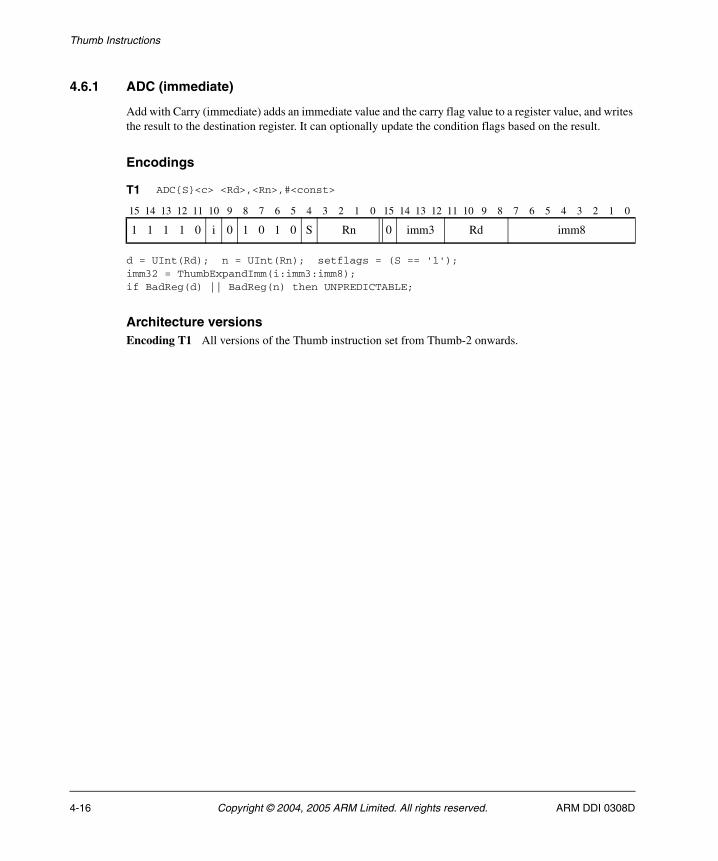
Thumb Instructions
4.6.1 ADC (immediate)
Add with Carry (immediate) adds an immediate value and the carry flag value to a register value, and writes the result to the destination register. It can optionally update the condition flags based on the result.
Encodings
d = UInt(Rd); n = UInt(Rn); setflags = (S == '1');imm32 = ThumbExpandImm(i:imm3:imm8);if BadReg(d) || BadReg(n) then UNPREDICTABLE;
Architecture versionsEncoding T1 All versions of the Thumb instruction set from Thumb-2 onwards.
T1 ADC{S}<c> <Rd>,<Rn>,#<const>
15 14 13 12 11 10 9 8 7 6 5 4 3 2 1 0 15 14 13 12 11 10 9 8 7 6 5 4 3 2 1 0
1 1 1 1 0 i 0 1 0 1 0 S Rn 0 imm3 Rd imm8
4-16 Copyright © 2004, 2005 ARM Limited. All rights reserved. ARM DDI 0308D
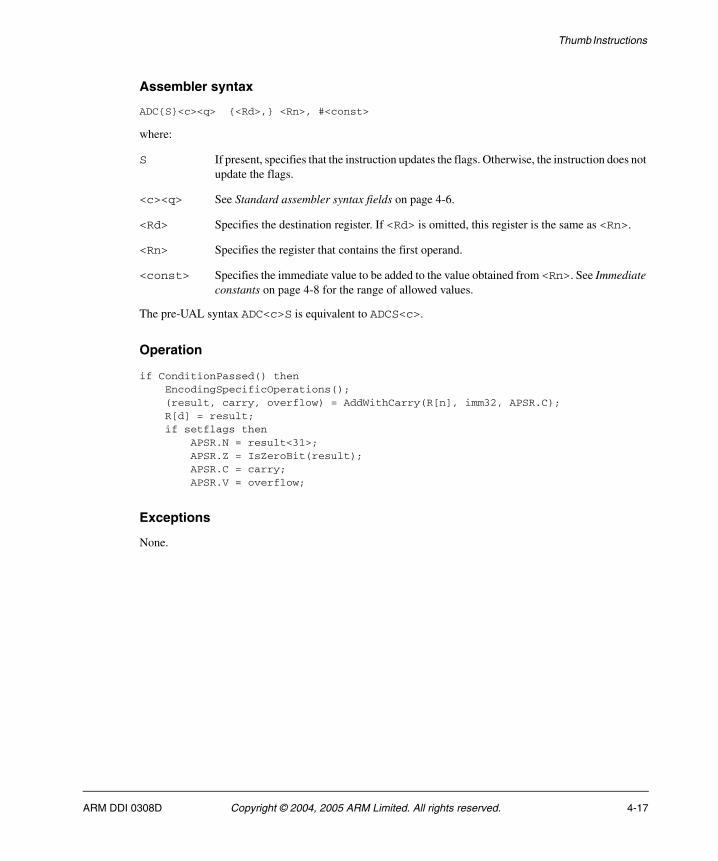
Thumb Instructions
Assembler syntax
ADC{S}<c><q> {<Rd>,} <Rn>, #<const>
where:
S If present, specifies that the instruction updates the flags. Otherwise, the instruction does not update the flags.
<c><q> See Standard assembler syntax fields on page 4-6.
<Rd> Specifies the destination register. If <Rd> is omitted, this register is the same as <Rn>.
<Rn> Specifies the register that contains the first operand.
<const> Specifies the immediate value to be added to the value obtained from <Rn>. See Immediate constants on page 4-8 for the range of allowed values.
The pre-UAL syntax ADC<c>S is equivalent to ADCS<c>.
Operation
if ConditionPassed() then EncodingSpecificOperations(); (result, carry, overflow) = AddWithCarry(R[n], imm32, APSR.C); R[d] = result; if setflags then APSR.N = result<31>; APSR.Z = IsZeroBit(result); APSR.C = carry; APSR.V = overflow;
Exceptions
None.
ARM DDI 0308D Copyright © 2004, 2005 ARM Limited. All rights reserved. 4-17
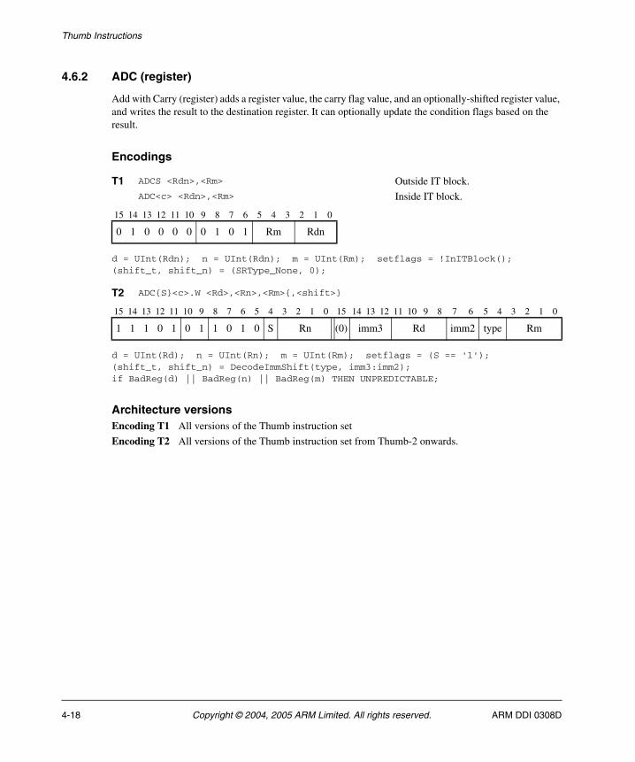
Thumb Instructions
4.6.2 ADC (register)
Add with Carry (register) adds a register value, the carry flag value, and an optionally-shifted register value, and writes the result to the destination register. It can optionally update the condition flags based on the result.
Encodings
d = UInt(Rdn); n = UInt(Rdn); m = UInt(Rm); setflags = !InITBlock();(shift_t, shift_n) = (SRType_None, 0);
d = UInt(Rd); n = UInt(Rn); m = UInt(Rm); setflags = (S == '1');(shift_t, shift_n) = DecodeImmShift(type, imm3:imm2);if BadReg(d) || BadReg(n) || BadReg(m) THEN UNPREDICTABLE;
Architecture versionsEncoding T1 All versions of the Thumb instruction set
Encoding T2 All versions of the Thumb instruction set from Thumb-2 onwards.
T1 ADCS <Rdn>,<Rm> Outside IT block.ADC<c> <Rdn>,<Rm> Inside IT block.
15 14 13 12 11 10 9 8 7 6 5 4 3 2 1 0
0 1 0 0 0 0 0 1 0 1 Rm Rdn
T2 ADC{S}<c>.W <Rd>,<Rn>,<Rm>{,<shift>}
15 14 13 12 11 10 9 8 7 6 5 4 3 2 1 0 15 14 13 12 11 10 9 8 7 6 5 4 3 2 1 0
1 1 1 0 1 0 1 1 0 1 0 S Rn (0) imm3 Rd imm2 type Rm
4-18 Copyright © 2004, 2005 ARM Limited. All rights reserved. ARM DDI 0308D

Thumb Instructions
Assembler syntax
ADC{S}<c><q> {<Rd>,} <Rn>, <Rm> {,<shift>}
where:
S If present, specifies that the instruction updates the flags. Otherwise, the instruction does not update the flags.
<c><q> See Standard assembler syntax fields on page 4-6.
<Rd> Specifies the destination register. If <Rd> is omitted, this register is the same as <Rn>.
<Rn> Specifies the register that contains the first operand.
<Rm> Specifies the register that is optionally shifted and used as the second operand.
<shift> Specifies the shift to apply to the value read from <Rm>. If <shift> is omitted, no shift is applied and both encodings are permitted. If <shift> is specified, only encoding T2 is permitted. The possible shifts and how they are encoded are described in Constant shifts applied to a register on page 4-10.
A special case is that if ADC<c> <Rd>,<Rn>,<Rd> is written with <Rd> and <Rn> both in the range R0-R7, it will be assembled using encoding T2 as though ADC<c> <Rd>,<Rn> had been written. To prevent this happening, use the .W qualifier.
The pre-UAL syntax ADC<c>S is equivalent to ADCS<c>.
Operation
if ConditionPassed() then EncodingSpecificOperations(); shifted = Shift(R[m], shift_t, shift_n, APSR.C); (result, carry, overflow) = AddWithCarry(R[n], shifted, APSR.C); R[d] = result; if setflags then APSR.N = result<31>; APSR.Z = IsZeroBit(result); APSR.C = carry; APSR.V = overflow;
Exceptions
None.
ARM DDI 0308D Copyright © 2004, 2005 ARM Limited. All rights reserved. 4-19
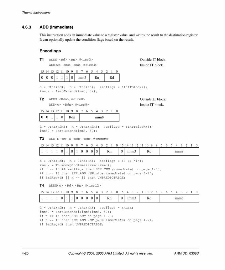
Thumb Instructions
4.6.3 ADD (immediate)
This instruction adds an immediate value to a register value, and writes the result to the destination register. It can optionally update the condition flags based on the result.
Encodings
d = UInt(Rd); n = UInt(Rn); setflags = !InITBlock();imm32 = ZeroExtend(imm3, 32);
d = UInt(Rdn); n = UInt(Rdn); setflags = !InITBlock();imm32 = ZeroExtend(imm8, 32);
d = UInt(Rd); n = UInt(Rn); setflags = (S == '1');imm32 = ThumbExpandImm(i:imm3:imm8);if d == 15 && setflags then SEE CMN (immediate) on page 4-68;if n == 13 then SEE ADD (SP plus immediate) on page 4-24;if BadReg(d) || n == 15 then UNPREDICTABLE;
d = UInt(Rd); n = UInt(Rn); setflags = FALSE;imm32 = ZeroExtend(i:imm3:imm8, 32);if n == 15 then SEE ADR on page 4-28;if n == 13 then SEE ADD (SP plus immediate) on page 4-24;if BadReg(d) then UNPREDICTABLE;
T1 ADDS <Rd>,<Rn>,#<imm3> Outside IT block.ADD<c> <Rd>,<Rn>,#<imm3> Inside IT block.
15 14 13 12 11 10 9 8 7 6 5 4 3 2 1 0
0 0 0 1 1 1 0 imm3 Rn Rd
T2 ADDS <Rdn>,#<imm8> Outside IT block.ADD<c> <Rdn>,#<imm8> Inside IT block.
15 14 13 12 11 10 9 8 7 6 5 4 3 2 1 0
0 0 1 1 0 Rdn imm8
T3 ADD{S}<c>.W <Rd>,<Rn>,#<const>
15 14 13 12 11 10 9 8 7 6 5 4 3 2 1 0 15 14 13 12 11 10 9 8 7 6 5 4 3 2 1 0
1 1 1 1 0 i 0 1 0 0 0 S Rn 0 imm3 Rd imm8
T4 ADDW<c> <Rd>,<Rn>,#<imm12>
15 14 13 12 11 10 9 8 7 6 5 4 3 2 1 0 15 14 13 12 11 10 9 8 7 6 5 4 3 2 1 0
1 1 1 1 0 i 1 0 0 0 0 0 Rn 0 imm3 Rd imm8
4-20 Copyright © 2004, 2005 ARM Limited. All rights reserved. ARM DDI 0308D
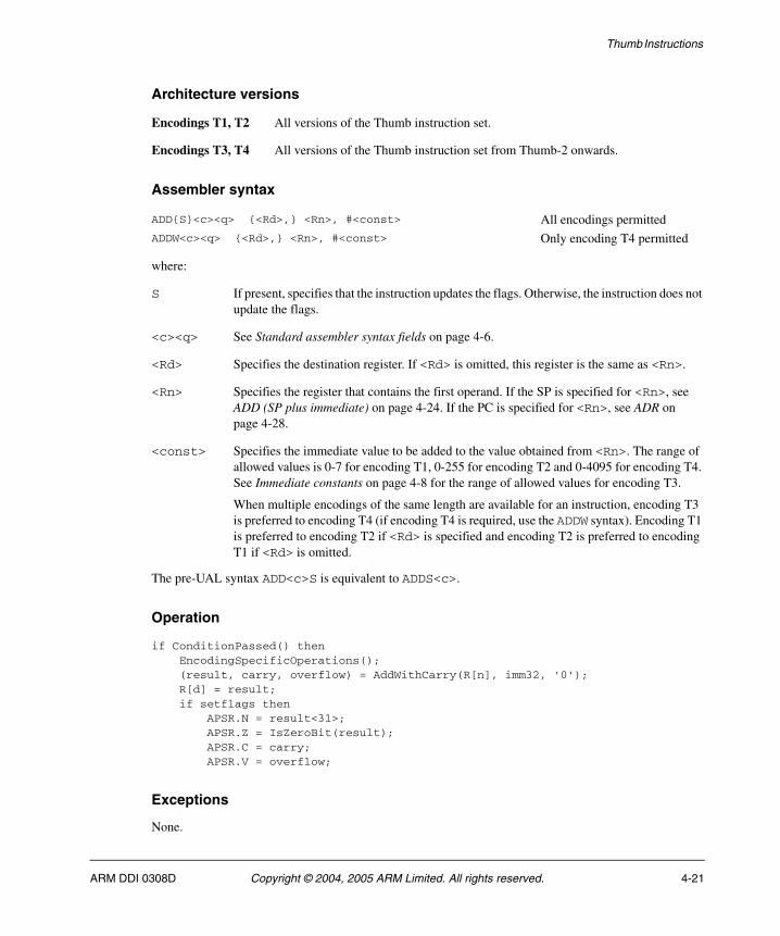
Thumb Instructions
Architecture versions
Encodings T1, T2 All versions of the Thumb instruction set.
Encodings T3, T4 All versions of the Thumb instruction set from Thumb-2 onwards.
Assembler syntax
where:
S If present, specifies that the instruction updates the flags. Otherwise, the instruction does not update the flags.
<c><q> See Standard assembler syntax fields on page 4-6.
<Rd> Specifies the destination register. If <Rd> is omitted, this register is the same as <Rn>.
<Rn> Specifies the register that contains the first operand. If the SP is specified for <Rn>, see ADD (SP plus immediate) on page 4-24. If the PC is specified for <Rn>, see ADR on page 4-28.
<const> Specifies the immediate value to be added to the value obtained from <Rn>. The range of allowed values is 0-7 for encoding T1, 0-255 for encoding T2 and 0-4095 for encoding T4. See Immediate constants on page 4-8 for the range of allowed values for encoding T3.
When multiple encodings of the same length are available for an instruction, encoding T3 is preferred to encoding T4 (if encoding T4 is required, use the ADDW syntax). Encoding T1 is preferred to encoding T2 if <Rd> is specified and encoding T2 is preferred to encoding T1 if <Rd> is omitted.
The pre-UAL syntax ADD<c>S is equivalent to ADDS<c>.
Operation
if ConditionPassed() then EncodingSpecificOperations(); (result, carry, overflow) = AddWithCarry(R[n], imm32, '0'); R[d] = result; if setflags then APSR.N = result<31>; APSR.Z = IsZeroBit(result); APSR.C = carry; APSR.V = overflow;
Exceptions
None.
ADD{S}<c><q> {<Rd>,} <Rn>, #<const> All encodings permittedADDW<c><q> {<Rd>,} <Rn>, #<const> Only encoding T4 permitted
ARM DDI 0308D Copyright © 2004, 2005 ARM Limited. All rights reserved. 4-21
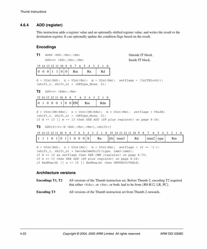
Thumb Instructions
4.6.4 ADD (register)
This instruction adds a register value and an optionally-shifted register value, and writes the result to the destination register. It can optionally update the condition flags based on the result.
Encodings
d = UInt(Rd); n = UInt(Rn); m = UInt(Rm); setflags = !InITBlock();(shift_t, shift_n) = (SRType_None, 0);
d = UInt(DN:Rdn); n = UInt(DN:Rdn); m = UInt(Rm); setflags = FALSE;(shift_t, shift_n) = (SRType_None, 0);if d == 13 || m == 13 then SEE ADD (SP plus register) on page 4-26;
d = UInt(Rd); n = UInt(Rn); m = UInt(Rm); setflags = (S == '1');(shift_t, shift_n) = DecodeImmShift(type, imm3:imm2);if d == 15 && setflags then SEE CMN (register) on page 4-70;if n == 13 then SEE ADD (SP plus register) on page 4-26;if BadReg(d) || n == 15 || BadReg(m) then UNPREDICTABLE;
Architecture versions
Encodings T1, T2 All versions of the Thumb instruction set. Before Thumb-2, encoding T2 required that either <Rdn>, or <Rm>, or both, had to be from {R8-R12, LR, PC}.
Encoding T3 All versions of the Thumb instruction set from Thumb-2 onwards.
T1 ADDS <Rd>,<Rn>,<Rm> Outside IT block.ADD<c> <Rd>,<Rn>,<Rm> Inside IT block.
15 14 13 12 11 10 9 8 7 6 5 4 3 2 1 0
0 0 0 1 1 0 0 Rm Rn Rd
T2 ADD<c> <Rdn>,<Rm>
15 14 13 12 11 10 9 8 7 6 5 4 3 2 1 0
0 1 0 0 0 1 0 0 DN Rm Rdn
T3 ADD{S}<c>.W <Rd>,<Rn>,<Rm>{,<shift>}
15 14 13 12 11 10 9 8 7 6 5 4 3 2 1 0 15 14 13 12 11 10 9 8 7 6 5 4 3 2 1 0
1 1 1 0 1 0 1 1 0 0 0 S Rn (0) imm3 Rd imm2 type Rm
4-22 Copyright © 2004, 2005 ARM Limited. All rights reserved. ARM DDI 0308D
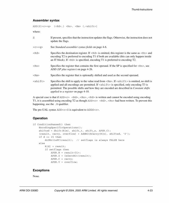
Thumb Instructions
Assembler syntax
ADD{S}<c><q> {<Rd>,} <Rn>, <Rm> {,<shift>}
where:
S If present, specifies that the instruction updates the flags. Otherwise, the instruction does not update the flags.
<c><q> See Standard assembler syntax fields on page 4-6.
<Rd> Specifies the destination register. If <Rd> is omitted, this register is the same as <Rn> and encoding T2 is preferred to encoding T1 if both are available (this can only happen inside an IT block). If <Rd> is specified, encoding T1 is preferred to encoding T2.
<Rn> Specifies the register that contains the first operand. If the SP is specified for <Rn>, see ADD (SP plus register) on page 4-26.
<Rm> Specifies the register that is optionally shifted and used as the second operand.
<shift> Specifies the shift to apply to the value read from <Rm>. If <shift> is omitted, no shift is applied and all encodings are permitted. If <shift> is specified, only encoding T3 is permitted. The possible shifts and how they are encoded are described in Constant shifts applied to a register on page 4-10.
A special case is that if ADD<c> <Rd>,<Rn>,<Rd> is written and cannot be encoded using encoding T1, it is assembled using encoding T2 as though ADD<c> <Rd>,<Rn> had been written. To prevent this happening, use the .W qualifier.
The pre-UAL syntax ADD<c>S is equivalent to ADDS<c>.
Operation
if ConditionPassed() then EncodingSpecificOperations(); shifted = Shift(R[m], shift_t, shift_n, APSR.C); (result, carry, overflow) = AddWithCarry(R[n], shifted, '0'); if d == 15 then ALUWritePC(result); // setflags is always FALSE here else R[d] = result; if setflags then APSR.N = result<31>; APSR.Z = IsZeroBit(result); APSR.C = carry; APSR.V = overflow;
Exceptions
None.
ARM DDI 0308D Copyright © 2004, 2005 ARM Limited. All rights reserved. 4-23
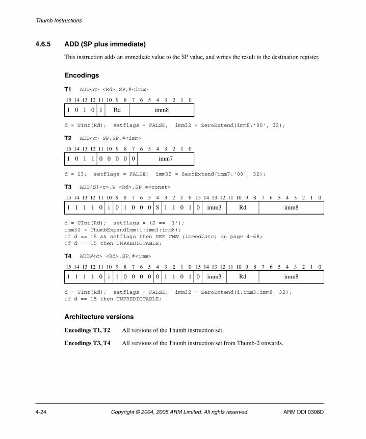
Thumb Instructions
4.6.5 ADD (SP plus immediate)
This instruction adds an immediate value to the SP value, and writes the result to the destination register.
Encodings
d = UInt(Rd); setflags = FALSE; imm32 = ZeroExtend(imm8:'00', 32);
d = 13; setflags = FALSE; imm32 = ZeroExtend(imm7:'00', 32);
d = UInt(Rd); setflags = (S == '1');imm32 = ThumbExpandImm(i:imm3:imm8);if d == 15 && setflags then SEE CMN (immediate) on page 4-68;if d == 15 then UNPREDICTABLE;
d = UInt(Rd); setflags = FALSE; imm32 = ZeroExtend(i:imm3:imm8, 32);if d == 15 then UNPREDICTABLE;
Architecture versions
Encodings T1, T2 All versions of the Thumb instruction set.
Encodings T3, T4 All versions of the Thumb instruction set from Thumb-2 onwards.
T1 ADD<c> <Rd>,SP,#<imm>
15 14 13 12 11 10 9 8 7 6 5 4 3 2 1 0
1 0 1 0 1 Rd imm8
T2 ADD<c> SP,SP,#<imm>
15 14 13 12 11 10 9 8 7 6 5 4 3 2 1 0
1 0 1 1 0 0 0 0 0 imm7
T3 ADD{S}<c>.W <Rd>,SP,#<const>
15 14 13 12 11 10 9 8 7 6 5 4 3 2 1 0 15 14 13 12 11 10 9 8 7 6 5 4 3 2 1 0
1 1 1 1 0 i 0 1 0 0 0 S 1 1 0 1 0 imm3 Rd imm8
T4 ADDW<c> <Rd>,SP,#<imm>
15 14 13 12 11 10 9 8 7 6 5 4 3 2 1 0 15 14 13 12 11 10 9 8 7 6 5 4 3 2 1 0
1 1 1 1 0 i 1 0 0 0 0 0 1 1 0 1 0 imm3 Rd imm8
4-24 Copyright © 2004, 2005 ARM Limited. All rights reserved. ARM DDI 0308D
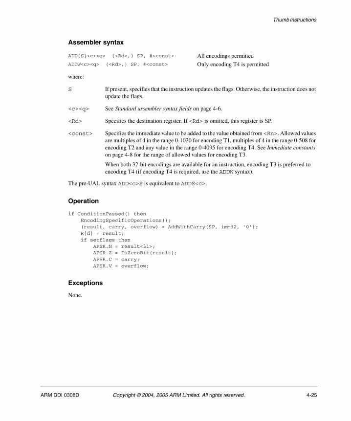
Thumb Instructions
Assembler syntax
where:
S If present, specifies that the instruction updates the flags. Otherwise, the instruction does not update the flags.
<c><q> See Standard assembler syntax fields on page 4-6.
<Rd> Specifies the destination register. If <Rd> is omitted, this register is SP.
<const> Specifies the immediate value to be added to the value obtained from <Rn>. Allowed values are multiples of 4 in the range 0-1020 for encoding T1, multiples of 4 in the range 0-508 for encoding T2 and any value in the range 0-4095 for encoding T4. See Immediate constants on page 4-8 for the range of allowed values for encoding T3.
When both 32-bit encodings are available for an instruction, encoding T3 is preferred to encoding T4 (if encoding T4 is required, use the ADDW syntax).
The pre-UAL syntax ADD<c>S is equivalent to ADDS<c>.
Operation
if ConditionPassed() then EncodingSpecificOperations(); (result, carry, overflow) = AddWithCarry(SP, imm32, '0'); R[d] = result; if setflags then APSR.N = result<31>; APSR.Z = IsZeroBit(result); APSR.C = carry; APSR.V = overflow;
Exceptions
None.
ADD{S}<c><q> {<Rd>,} SP, #<const> All encodings permittedADDW<c><q> {<Rd>,} SP, #<const> Only encoding T4 is permitted
ARM DDI 0308D Copyright © 2004, 2005 ARM Limited. All rights reserved. 4-25
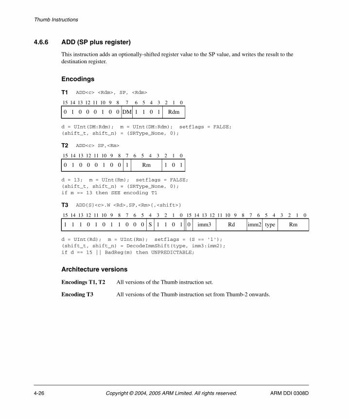
Thumb Instructions
4.6.6 ADD (SP plus register)
This instruction adds an optionally-shifted register value to the SP value, and writes the result to the destination register.
Encodings
d = UInt(DM:Rdm); m = UInt(DM:Rdm); setflags = FALSE;(shift_t, shift_n) = (SRType_None, 0);
d = 13; m = UInt(Rm); setflags = FALSE;(shift_t, shift_n) = (SRType_None, 0);if m == 13 then SEE encoding T1
d = UInt(Rd); m = UInt(Rm); setflags = (S == '1');(shift_t, shift_n) = DecodeImmShift(type, imm3:imm2);if d == 15 || BadReg(m) then UNPREDICTABLE;
Architecture versions
Encodings T1, T2 All versions of the Thumb instruction set.
Encoding T3 All versions of the Thumb instruction set from Thumb-2 onwards.
T1 ADD<c> <Rdm>, SP, <Rdm>
15 14 13 12 11 10 9 8 7 6 5 4 3 2 1 0
0 1 0 0 0 1 0 0 DM 1 1 0 1 Rdm
T2 ADD<c> SP,<Rm>
15 14 13 12 11 10 9 8 7 6 5 4 3 2 1 0
0 1 0 0 0 1 0 0 1 Rm 1 0 1
T3 ADD{S}<c>.W <Rd>,SP,<Rm>{,<shift>}
15 14 13 12 11 10 9 8 7 6 5 4 3 2 1 0 15 14 13 12 11 10 9 8 7 6 5 4 3 2 1 0
1 1 1 0 1 0 1 1 0 0 0 S 1 1 0 1 0 imm3 Rd imm2 type Rm
4-26 Copyright © 2004, 2005 ARM Limited. All rights reserved. ARM DDI 0308D
Thumb Instructions
Assembler syntax
ADD{S}<c><q> {<Rd>,} SP, <Rm>{, <shift>}
where:
S If present, specifies that the instruction updates the flags. Otherwise, the instruction does not update the flags.
<c><q> See Standard assembler syntax fields on page 4-6.
<Rd> Specifies the destination register. If <Rd> is omitted, this register is SP.
<Rm> Specifies the register that is optionally shifted and used as the second operand.
<shift> Specifies the shift to apply to the value read from <Rm>. If <shift> is omitted, no shift is applied and all encodings are permitted. If <shift> is specified, only encoding T3 is permitted. The possible shifts and how they are encoded are described in Constant shifts applied to a register on page 4-10.
The pre-UAL syntax ADD<c>S is equivalent to ADDS<c>.
Operation
if ConditionPassed() then EncodingSpecificOperations(); shifted = Shift(R[m], shift_t, shift_n, APSR.C); (result, carry, overflow) = AddWithCarry(SP, shifted, '0'); R[d] = result; if setflags then APSR.N = result<31>; APSR.Z = IsZeroBit(result); APSR.C = carry; APSR.V = overflow;
Exceptions
None.
ARM DDI 0308D Copyright © 2004, 2005 ARM Limited. All rights reserved. 4-27
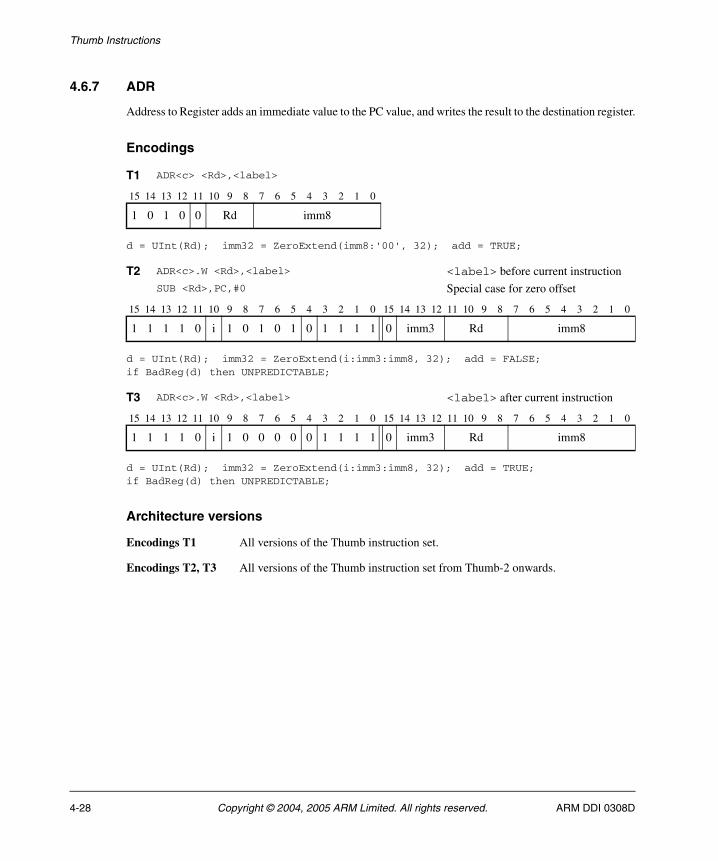
Thumb Instructions
4.6.7 ADR
Address to Register adds an immediate value to the PC value, and writes the result to the destination register.
Encodings
d = UInt(Rd); imm32 = ZeroExtend(imm8:'00', 32); add = TRUE;
d = UInt(Rd); imm32 = ZeroExtend(i:imm3:imm8, 32); add = FALSE;if BadReg(d) then UNPREDICTABLE;
d = UInt(Rd); imm32 = ZeroExtend(i:imm3:imm8, 32); add = TRUE;if BadReg(d) then UNPREDICTABLE;
Architecture versions
Encodings T1 All versions of the Thumb instruction set.
Encodings T2, T3 All versions of the Thumb instruction set from Thumb-2 onwards.
T1 ADR<c> <Rd>,<label>
15 14 13 12 11 10 9 8 7 6 5 4 3 2 1 0
1 0 1 0 0 Rd imm8
T2 ADR<c>.W <Rd>,<label> <label> before current instructionSUB <Rd>,PC,#0 Special case for zero offset
15 14 13 12 11 10 9 8 7 6 5 4 3 2 1 0 15 14 13 12 11 10 9 8 7 6 5 4 3 2 1 0
1 1 1 1 0 i 1 0 1 0 1 0 1 1 1 1 0 imm3 Rd imm8
T3 ADR<c>.W <Rd>,<label> <label> after current instruction
15 14 13 12 11 10 9 8 7 6 5 4 3 2 1 0 15 14 13 12 11 10 9 8 7 6 5 4 3 2 1 0
1 1 1 1 0 i 1 0 0 0 0 0 1 1 1 1 0 imm3 Rd imm8
4-28 Copyright © 2004, 2005 ARM Limited. All rights reserved. ARM DDI 0308D

Thumb Instructions
Assembler syntax
where:
<c><q> See Standard assembler syntax fields on page 4-6.
<Rd> Specifies the destination register.
<label> Specifies the label of an instruction or literal data item whose address is to be loaded into <Rd>. The assembler calculates the required value of the offset from the Align(PC,4) value of the ADR instruction to this label.
If the offset is positive, encodings T1 and T3 are permitted with imm32 equal to the offset. Allowed values of the offset are multiples of four in the range 0 to 1020 for encoding T1 and any value in the range 0 to 4095 for encoding T3.
If the offset is negative, encoding T2 is permitted with imm32 equal to minus the offset. Allowed values of the offset are -4095 to -1.
In the alternative syntax forms:
<const> Specifies the offset value for the ADD form and minus the offset value for the SUB form. Allowed values are multiples of four in the range 0 to 1020 for encoding T1 and any value in the range 0 to 4095 for encodings T2 and T3.
Note It is recommended that the alternative syntax forms are avoided where possible. However,
the only possible syntax for encoding T2 with all immediate bits zero is SUB<c><q> <Rd>,PC,#0.
Operation
if ConditionPassed() then EncodingSpecificOperations(); base = Align(PC, 4); // Word-aligned PC R[d] = if add then (base + imm32) else (base - imm32);
Exceptions
None.
ADR<c><q> <Rd>, <label> Normal syntaxADD<c><q> <Rd>, PC, #<const> Alternative for encodings T1, T3SUB<c><q> <Rd>, PC, #<const> Alternative for encoding T2
ARM DDI 0308D Copyright © 2004, 2005 ARM Limited. All rights reserved. 4-29
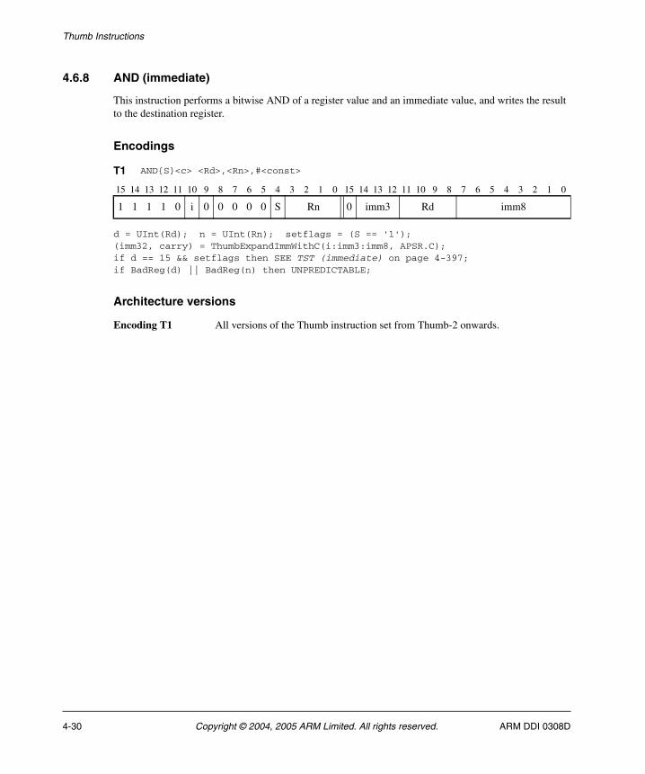
Thumb Instructions
4.6.8 AND (immediate)
This instruction performs a bitwise AND of a register value and an immediate value, and writes the result to the destination register.
Encodings
d = UInt(Rd); n = UInt(Rn); setflags = (S == '1');(imm32, carry) = ThumbExpandImmWithC(i:imm3:imm8, APSR.C);if d == 15 && setflags then SEE TST (immediate) on page 4-397;if BadReg(d) || BadReg(n) then UNPREDICTABLE;
Architecture versions
Encoding T1 All versions of the Thumb instruction set from Thumb-2 onwards.
T1 AND{S}<c> <Rd>,<Rn>,#<const>
15 14 13 12 11 10 9 8 7 6 5 4 3 2 1 0 15 14 13 12 11 10 9 8 7 6 5 4 3 2 1 0
1 1 1 1 0 i 0 0 0 0 0 S Rn 0 imm3 Rd imm8
4-30 Copyright © 2004, 2005 ARM Limited. All rights reserved. ARM DDI 0308D

Thumb Instructions
Assembler syntax
AND{S}<c><q> {<Rd>,} <Rn>, #<const>
where:
S If present, specifies that the instruction updates the flags. Otherwise, the instruction does not update the flags.
<c><q> See Standard assembler syntax fields on page 4-6.
<Rd> Specifies the destination register. If <Rd> is omitted, this register is the same as <Rn>.
<Rn> Specifies the register that contains the first operand.
<const> Specifies the immediate value to be added to the value obtained from <Rn>. See Immediate constants on page 4-8 for the range of allowed values.
The pre-UAL syntax AND<c>S is equivalent to ANDS<c>.
Operation
if ConditionPassed() then EncodingSpecificOperations(); result = R[n] AND imm32; R[d] = result; if setflags then APSR.N = result<31>; APSR.Z = IsZeroBit(result); APSR.C = carry; // APSR.V unchanged
Exceptions
None.
ARM DDI 0308D Copyright © 2004, 2005 ARM Limited. All rights reserved. 4-31
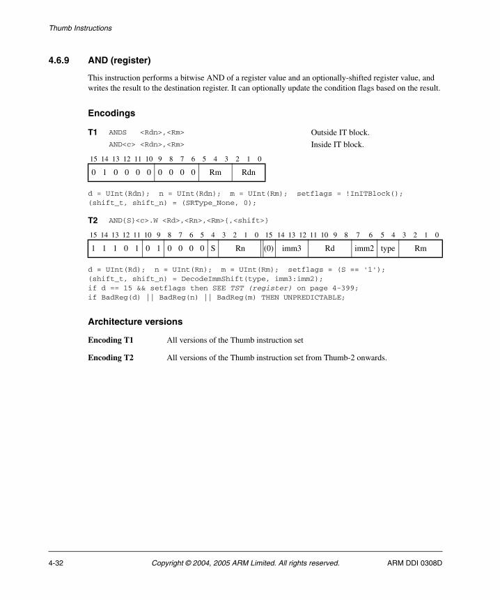
Thumb Instructions
4.6.9 AND (register)
This instruction performs a bitwise AND of a register value and an optionally-shifted register value, and writes the result to the destination register. It can optionally update the condition flags based on the result.
Encodings
d = UInt(Rdn); n = UInt(Rdn); m = UInt(Rm); setflags = !InITBlock();(shift_t, shift_n) = (SRType_None, 0);
d = UInt(Rd); n = UInt(Rn); m = UInt(Rm); setflags = (S == '1');(shift_t, shift_n) = DecodeImmShift(type, imm3:imm2);if d == 15 && setflags then SEE TST (register) on page 4-399;if BadReg(d) || BadReg(n) || BadReg(m) THEN UNPREDICTABLE;
Architecture versions
Encoding T1 All versions of the Thumb instruction set
Encoding T2 All versions of the Thumb instruction set from Thumb-2 onwards.
T1 ANDS <Rdn>,<Rm> Outside IT block.AND<c> <Rdn>,<Rm> Inside IT block.
15 14 13 12 11 10 9 8 7 6 5 4 3 2 1 0
0 1 0 0 0 0 0 0 0 0 Rm Rdn
T2 AND{S}<c>.W <Rd>,<Rn>,<Rm>{,<shift>}
15 14 13 12 11 10 9 8 7 6 5 4 3 2 1 0 15 14 13 12 11 10 9 8 7 6 5 4 3 2 1 0
1 1 1 0 1 0 1 0 0 0 0 S Rn (0) imm3 Rd imm2 type Rm
4-32 Copyright © 2004, 2005 ARM Limited. All rights reserved. ARM DDI 0308D

Thumb Instructions
Assembler syntax
AND{S}<c><q> {<Rd>,} <Rn>, <Rm> {,<shift>}
where:
S If present, specifies that the instruction updates the flags. Otherwise, the instruction does not update the flags.
<c><q> See Standard assembler syntax fields on page 4-6.
<Rd> Specifies the destination register. If <Rd> is omitted, this register is the same as <Rn>.
<Rn> Specifies the register that contains the first operand.
<Rm> Specifies the register that is optionally shifted and used as the second operand.
<shift> Specifies the shift to apply to the value read from <Rm>. If <shift> is omitted, no shift is applied and both encodings are permitted. If <shift> is specified, only encoding T2 is permitted. The possible shifts and how they are encoded are described in Constant shifts applied to a register on page 4-10.
A special case is that if AND<c> <Rd>,<Rn>,<Rd> is written with <Rd> and <Rn> both in the range R0-R7, it will be assembled using encoding T2 as though AND<c> <Rd>,<Rn> had been written. To prevent this happening, use the .W qualifier.
The pre-UAL syntax AND<c>S is equivalent to ANDS<c>.
Operation
if ConditionPassed() then EncodingSpecificOperations(); (shifted, carry) = Shift_C(R[m], shift_t, shift_n, APSR.C); result = R[n] AND shifted; R[d] = result; if setflags then APSR.N = result<31>; APSR.Z = IsZeroBit(result); APSR.C = carry; // APSR.V unchanged
Exceptions
None.
ARM DDI 0308D Copyright © 2004, 2005 ARM Limited. All rights reserved. 4-33
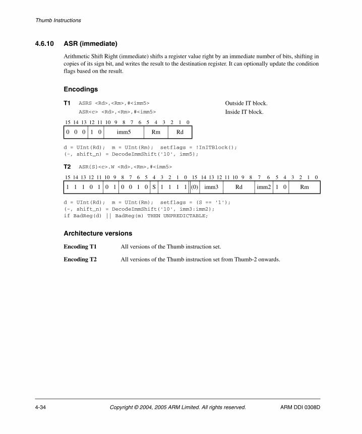
Thumb Instructions
4.6.10 ASR (immediate)
Arithmetic Shift Right (immediate) shifts a register value right by an immediate number of bits, shifting in copies of its sign bit, and writes the result to the destination register. It can optionally update the condition flags based on the result.
Encodings
d = UInt(Rd); m = UInt(Rm); setflags = !InITBlock();(-, shift_n) = DecodeImmShift('10', imm5);
d = UInt(Rd); m = UInt(Rm); setflags = (S == '1');(-, shift_n) = DecodeImmShift('10', imm3:imm2);if BadReg(d) || BadReg(m) THEN UNPREDICTABLE;
Architecture versions
Encoding T1 All versions of the Thumb instruction set.
Encoding T2 All versions of the Thumb instruction set from Thumb-2 onwards.
T1 ASRS <Rd>,<Rm>,#<imm5> Outside IT block.ASR<c> <Rd>,<Rm>,#<imm5> Inside IT block.
15 14 13 12 11 10 9 8 7 6 5 4 3 2 1 0
0 0 0 1 0 imm5 Rm Rd
T2 ASR{S}<c>.W <Rd>,<Rm>,#<imm5>
15 14 13 12 11 10 9 8 7 6 5 4 3 2 1 0 15 14 13 12 11 10 9 8 7 6 5 4 3 2 1 0
1 1 1 0 1 0 1 0 0 1 0 S 1 1 1 1 (0) imm3 Rd imm2 1 0 Rm
4-34 Copyright © 2004, 2005 ARM Limited. All rights reserved. ARM DDI 0308D

Thumb Instructions
Assembler syntax
ASR{S}<c><q> <Rd>, <Rm>, #<imm5>
where:
S If present, specifies that the instruction updates the flags. Otherwise, the instruction does not update the flags.
<c><q> See Standard assembler syntax fields on page 4-6.
<Rd> Specifies the destination register.
<Rm> Specifies the register that contains the first operand.
<imm5> Specifies the shift amount, in the range 1 to 32. See Constant shifts applied to a register on page 4-10.
Operation
if ConditionPassed() then EncodingSpecificOperations(); (result, carry) = Shift_C(R[m], SRType_ASR, shift_n, APSR.C); R[d] = result; if setflags then APSR.N = result<31>; APSR.Z = IsZeroBit(result); APSR.C = carry; // APSR.V unchanged
Exceptions
None.
ARM DDI 0308D Copyright © 2004, 2005 ARM Limited. All rights reserved. 4-35

Thumb Instructions
4.6.11 ASR (register)
Arithmetic Shift Right (register) shifts a register value right by a variable number of bits, shifting in copies of its sign bit, and writes the result to the destination register. The variable number of bits is read from the bottom byte of a register. It can optionally update the condition flags based on the result.
Encodings
d = UInt(Rdn); n = UInt(Rdn); m = UInt(Rm); setflags = !InITBlock();
d = UInt(Rd); n = UInt(Rn); m = UInt(Rm); setflags = (S == '1');if BadReg(d) || BadReg(n) || BadReg(m) then UNPREDICTABLE;
Architecture versions
Encoding T1 All versions of the Thumb instruction set
Encoding T2 All versions of the Thumb instruction set from Thumb-2 onwards.
T1 ASRS <Rdn>,<Rm> Outside IT block.ASR<c> <Rdn>,<Rm> Inside IT block.
15 14 13 12 11 10 9 8 7 6 5 4 3 2 1 0
0 1 0 0 0 0 0 1 0 0 Rm Rdn
T2 ASR{S}<c>.W <Rd>,<Rn>,<Rm>
15 14 13 12 11 10 9 8 7 6 5 4 3 2 1 0 15 14 13 12 11 10 9 8 7 6 5 4 3 2 1 0
1 1 1 1 1 0 1 0 0 1 0 S Rn 1 1 1 1 Rd 0 0 0 0 Rm
4-36 Copyright © 2004, 2005 ARM Limited. All rights reserved. ARM DDI 0308D
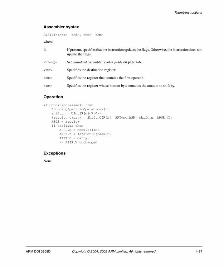
Thumb Instructions
Assembler syntax
ASR{S}<c><q> <Rd>, <Rn>, <Rm>
where:
S If present, specifies that the instruction updates the flags. Otherwise, the instruction does not update the flags.
<c><q> See Standard assembler syntax fields on page 4-6.
<Rd> Specifies the destination register.
<Rn> Specifies the register that contains the first operand.
<Rm> Specifies the register whose bottom byte contains the amount to shift by.
Operation
if ConditionPassed() then EncodingSpecificOperations(); shift_n = UInt(R[m]<7:0>); (result, carry) = Shift_C(R[n], SRType_ASR, shift_n, APSR.C); R[d] = result; if setflags then APSR.N = result<31>; APSR.Z = IsZeroBit(result); APSR.C = carry; // APSR.V unchanged
Exceptions
None.
ARM DDI 0308D Copyright © 2004, 2005 ARM Limited. All rights reserved. 4-37
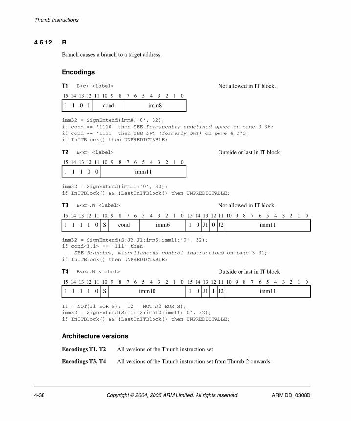
Thumb Instructions
4.6.12 B
Branch causes a branch to a target address.
Encodings
imm32 = SignExtend(imm8:'0', 32);if cond == '1110' then SEE Permanently undefined space on page 3-36;if cond == '1111' then SEE SVC (formerly SWI) on page 4-375;if InITBlock() then UNPREDICTABLE;
imm32 = SignExtend(imm11:'0', 32);if InITBlock() && !LastInITBlock() then UNPREDICTABLE;
imm32 = SignExtend(S:J2:J1:imm6:imm11:'0', 32);if cond<3:1> == '111' then SEE Branches, miscellaneous control instructions on page 3-31;if InITBlock() then UNPREDICTABLE;
I1 = NOT(J1 EOR S); I2 = NOT(J2 EOR S);imm32 = SignExtend(S:I1:I2:imm10:imm11:'0', 32);if InITBlock() && !LastInITBlock() then UNPREDICTABLE;
Architecture versions
Encodings T1, T2 All versions of the Thumb instruction set
Encodings T3, T4 All versions of the Thumb instruction set from Thumb-2 onwards.
T1 B<c> <label> Not allowed in IT block.
15 14 13 12 11 10 9 8 7 6 5 4 3 2 1 0
1 1 0 1 cond imm8
T2 B<c> <label> Outside or last in IT block
15 14 13 12 11 10 9 8 7 6 5 4 3 2 1 0
1 1 1 0 0 imm11
T3 B<c>.W <label> Not allowed in IT block.
15 14 13 12 11 10 9 8 7 6 5 4 3 2 1 0 15 14 13 12 11 10 9 8 7 6 5 4 3 2 1 0
1 1 1 1 0 S cond imm6 1 0 J1 0 J2 imm11
T4 B<c>.W <label> Outside or last in IT block
15 14 13 12 11 10 9 8 7 6 5 4 3 2 1 0 15 14 13 12 11 10 9 8 7 6 5 4 3 2 1 0
1 1 1 1 0 S imm10 1 0 J1 1 J2 imm11
4-38 Copyright © 2004, 2005 ARM Limited. All rights reserved. ARM DDI 0308D
Thumb Instructions
Assembler syntax
B<c><q> <label>
where:
<c><q> See Standard assembler syntax fields on page 4-6.
Note Encodings T1 and T3 are conditional in their own right, and do not require an IT instruction
to make them conditional.
For encodings T1 and T3, <c> is not allowed to be AL or omitted. The 4-bit encoding of the condition is placed in the instruction and not in a preceding IT instruction, and the instruction is not allowed to be in an IT block. As a result, encodings T1 and T2 are never both available to the assembler, nor are encodings T3 and T4.
<label> Specifies the label of the instruction that is to be branched to. The assembler calculates the required value of the offset from the PC value of the B instruction to this label, then selects an encoding that will set imm32 to that offset.
Allowed offsets are even numbers in the range -256 to 254 for encoding T1, -2048 to 2046 for encoding T2, -1048576 to 1048574 for encoding T3, and -16777216 to 16777214 for encoding T4.
Operation
if ConditionPassed() then EncodingSpecificOperations(); BranchWritePC(PC + imm32);
Exceptions
None.
ARM DDI 0308D Copyright © 2004, 2005 ARM Limited. All rights reserved. 4-39
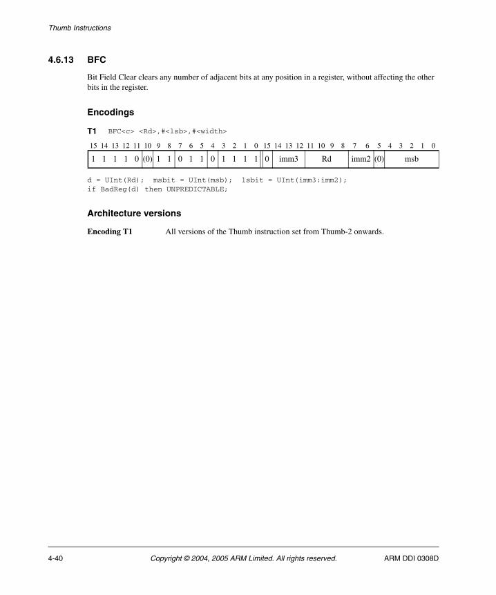
Thumb Instructions
4.6.13 BFC
Bit Field Clear clears any number of adjacent bits at any position in a register, without affecting the other bits in the register.
Encodings
d = UInt(Rd); msbit = UInt(msb); lsbit = UInt(imm3:imm2);if BadReg(d) then UNPREDICTABLE;
Architecture versions
Encoding T1 All versions of the Thumb instruction set from Thumb-2 onwards.
T1 BFC<c> <Rd>,#<lsb>,#<width>
15 14 13 12 11 10 9 8 7 6 5 4 3 2 1 0 15 14 13 12 11 10 9 8 7 6 5 4 3 2 1 0
1 1 1 1 0 (0) 1 1 0 1 1 0 1 1 1 1 0 imm3 Rd imm2 (0) msb
4-40 Copyright © 2004, 2005 ARM Limited. All rights reserved. ARM DDI 0308D
Thumb Instructions
Assembler syntax
BFC<c><q> <Rd>, #<lsb>, #<width>
where:
<c><q> See Standard assembler syntax fields on page 4-6.
<Rd> Specifies the destination register.
<lsb> Specifies the least significant bit that is to be cleared, in the range 0 to 31. This determines the required value of lsbit.
<width> Specifies the number of bits to be cleared, in the range 1 to 32-<lsb>. The required value of msbit is <lsb>+<width>-1.
Operation
if ConditionPassed() then EncodingSpecificOperations(); if msbit >= lsbit then R[d]<msbit:lsbit> = Replicate('0', msbit-lsbit+1); // Other bits of R[d] are unchanged else UNPREDICTABLE;
Exceptions
None.
ARM DDI 0308D Copyright © 2004, 2005 ARM Limited. All rights reserved. 4-41
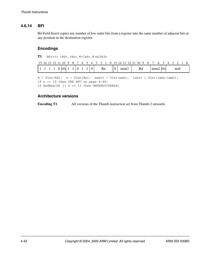
Thumb Instructions
4.6.14 BFI
Bit Field Insert copies any number of low order bits from a register into the same number of adjacent bits at any position in the destination register.
Encodings
d = UInt(Rd); n = UInt(Rn); msbit = UInt(msb); lsbit = UInt(imm3:imm2);if n == 15 then SEE BFC on page 4-40;if BadReg(d) || n == 13 then UNPREDICTABLE;
Architecture versions
Encoding T1 All versions of the Thumb instruction set from Thumb-2 onwards.
T1 BFI<c> <Rd>,<Rn>,#<lsb>,#<width>
15 14 13 12 11 10 9 8 7 6 5 4 3 2 1 0 15 14 13 12 11 10 9 8 7 6 5 4 3 2 1 0
1 1 1 1 0 (0) 1 1 0 1 1 0 Rn 0 imm3 Rd imm2 (0) msb
4-42 Copyright © 2004, 2005 ARM Limited. All rights reserved. ARM DDI 0308D

Thumb Instructions
Assembler syntax
BFI<c><q> <Rd>, <Rn>, #<lsb>, #<width>
where:
<c><q> See Standard assembler syntax fields on page 4-6.
<Rd> Specifies the destination register.
<Rn> Specifies the source register.
<lsb> Specifies the least significant destination bit.
<width> Specifies the number of bits to be copied.
Operation
if ConditionPassed() then EncodingSpecificOperations(); if msbit >= lsbit then R[d]<msbit:lsbit> = R[n]<(msbit-lsbit):0>; // Other bits of R[d] are unchanged else UNPREDICTABLE;
Exceptions
None.
ARM DDI 0308D Copyright © 2004, 2005 ARM Limited. All rights reserved. 4-43
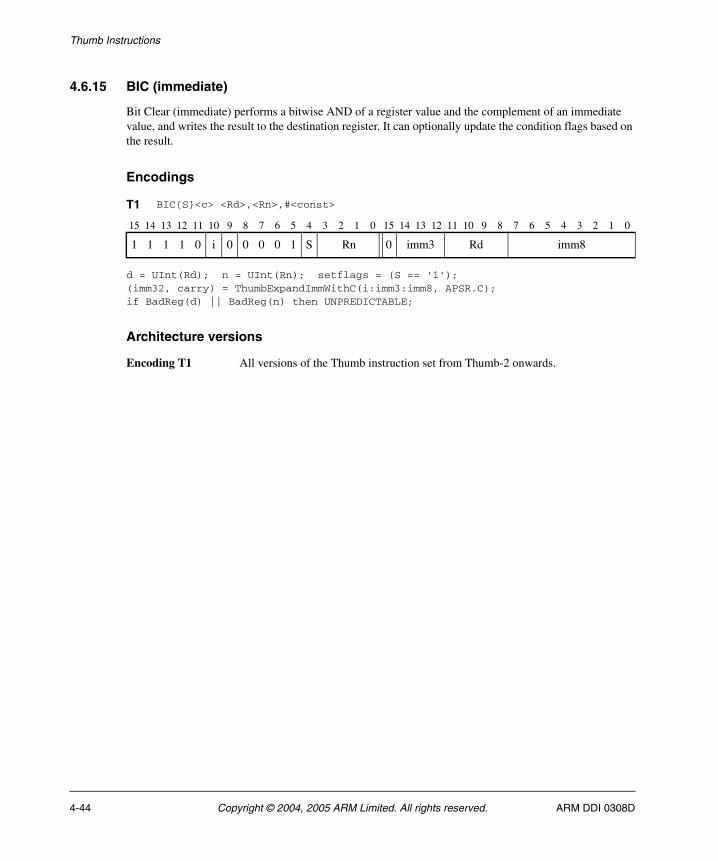
Thumb Instructions
4.6.15 BIC (immediate)
Bit Clear (immediate) performs a bitwise AND of a register value and the complement of an immediate value, and writes the result to the destination register. It can optionally update the condition flags based on the result.
Encodings
d = UInt(Rd); n = UInt(Rn); setflags = (S == '1');(imm32, carry) = ThumbExpandImmWithC(i:imm3:imm8, APSR.C);if BadReg(d) || BadReg(n) then UNPREDICTABLE;
Architecture versions
Encoding T1 All versions of the Thumb instruction set from Thumb-2 onwards.
T1 BIC{S}<c> <Rd>,<Rn>,#<const>
15 14 13 12 11 10 9 8 7 6 5 4 3 2 1 0 15 14 13 12 11 10 9 8 7 6 5 4 3 2 1 0
1 1 1 1 0 i 0 0 0 0 1 S Rn 0 imm3 Rd imm8
4-44 Copyright © 2004, 2005 ARM Limited. All rights reserved. ARM DDI 0308D

Thumb Instructions
Assembler syntax
BIC{S}<c><q> {<Rd>,} <Rn>, #<const>
where:
S If present, specifies that the instruction updates the flags. Otherwise, the instruction does not update the flags.
<c><q> See Standard assembler syntax fields on page 4-6.
<Rd> Specifies the destination register. If <Rd> is omitted, this register is the same as <Rn>.
<Rn> Specifies the register that contains the operand.
<const> Specifies the immediate value to be added to the value obtained from <Rn>. See Immediate constants on page 4-8 for the range of allowed values.
The pre-UAL syntax BIC<c>S is equivalent to BICS<c>.
Operation
if ConditionPassed() then EncodingSpecificOperations(); result = R[n] AND NOT(imm32); R[d] = result; if setflags then APSR.N = result<31>; APSR.Z = IsZeroBit(result); APSR.C = carry; // APSR.V unchanged
Exceptions
None.
ARM DDI 0308D Copyright © 2004, 2005 ARM Limited. All rights reserved. 4-45
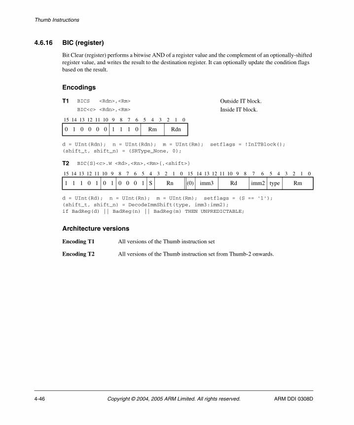
Thumb Instructions
4.6.16 BIC (register)
Bit Clear (register) performs a bitwise AND of a register value and the complement of an optionally-shifted register value, and writes the result to the destination register. It can optionally update the condition flags based on the result.
Encodings
d = UInt(Rdn); n = UInt(Rdn); m = UInt(Rm); setflags = !InITBlock();(shift_t, shift_n) = (SRType_None, 0);
d = UInt(Rd); n = UInt(Rn); m = UInt(Rm); setflags = (S == '1');(shift_t, shift_n) = DecodeImmShift(type, imm3:imm2);if BadReg(d) || BadReg(n) || BadReg(m) THEN UNPREDICTABLE;
Architecture versions
Encoding T1 All versions of the Thumb instruction set
Encoding T2 All versions of the Thumb instruction set from Thumb-2 onwards.
T1 BICS <Rdn>,<Rm> Outside IT block.BIC<c> <Rdn>,<Rm> Inside IT block.
15 14 13 12 11 10 9 8 7 6 5 4 3 2 1 0
0 1 0 0 0 0 1 1 1 0 Rm Rdn
T2 BIC{S}<c>.W <Rd>,<Rn>,<Rm>{,<shift>}
15 14 13 12 11 10 9 8 7 6 5 4 3 2 1 0 15 14 13 12 11 10 9 8 7 6 5 4 3 2 1 0
1 1 1 0 1 0 1 0 0 0 1 S Rn (0) imm3 Rd imm2 type Rm
4-46 Copyright © 2004, 2005 ARM Limited. All rights reserved. ARM DDI 0308D
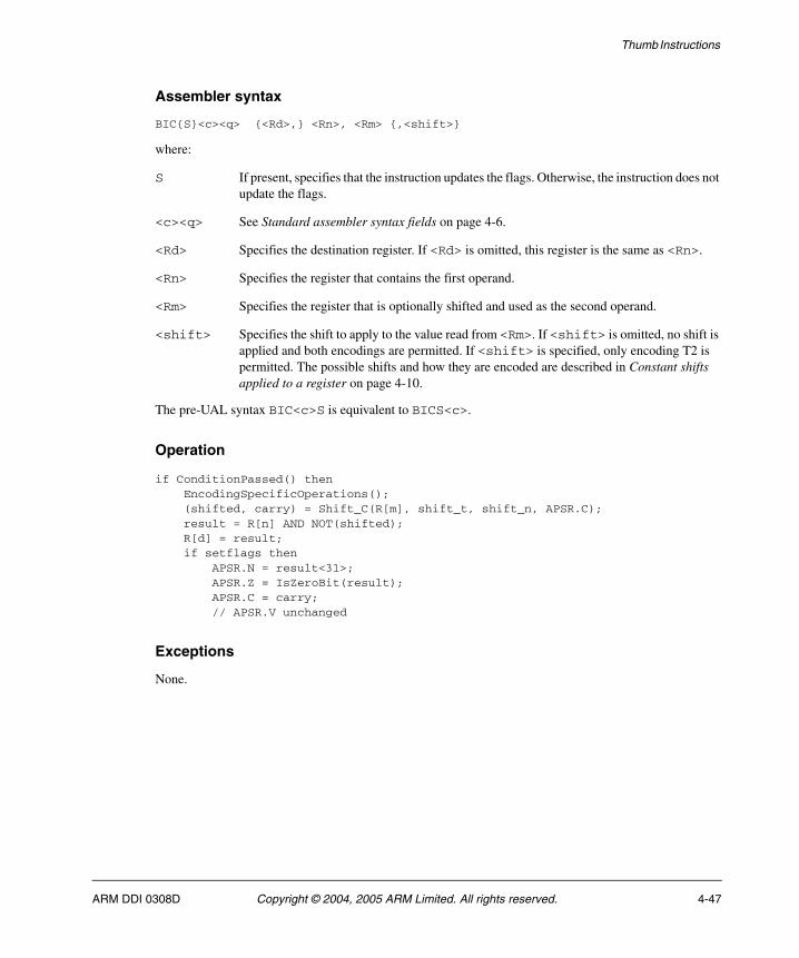
Thumb Instructions
Assembler syntax
BIC{S}<c><q> {<Rd>,} <Rn>, <Rm> {,<shift>}
where:
S If present, specifies that the instruction updates the flags. Otherwise, the instruction does not update the flags.
<c><q> See Standard assembler syntax fields on page 4-6.
<Rd> Specifies the destination register. If <Rd> is omitted, this register is the same as <Rn>.
<Rn> Specifies the register that contains the first operand.
<Rm> Specifies the register that is optionally shifted and used as the second operand.
<shift> Specifies the shift to apply to the value read from <Rm>. If <shift> is omitted, no shift is applied and both encodings are permitted. If <shift> is specified, only encoding T2 is permitted. The possible shifts and how they are encoded are described in Constant shifts applied to a register on page 4-10.
The pre-UAL syntax BIC<c>S is equivalent to BICS<c>.
Operation
if ConditionPassed() then EncodingSpecificOperations(); (shifted, carry) = Shift_C(R[m], shift_t, shift_n, APSR.C); result = R[n] AND NOT(shifted); R[d] = result; if setflags then APSR.N = result<31>; APSR.Z = IsZeroBit(result); APSR.C = carry; // APSR.V unchanged
Exceptions
None.
ARM DDI 0308D Copyright © 2004, 2005 ARM Limited. All rights reserved. 4-47
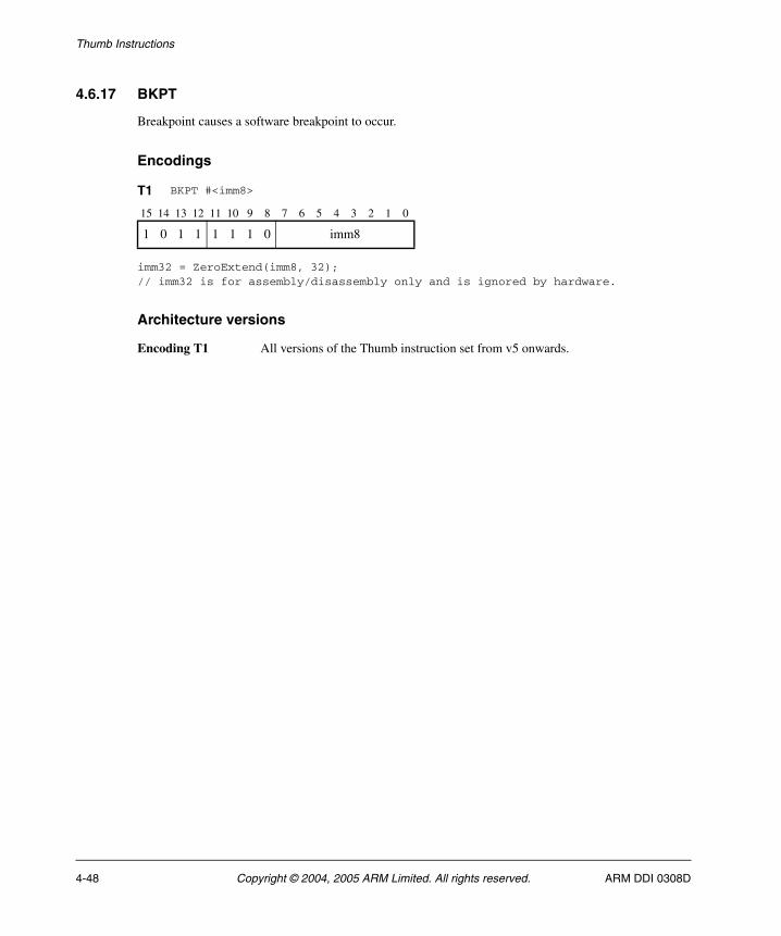
Thumb Instructions
4.6.17 BKPT
Breakpoint causes a software breakpoint to occur.
Encodings
imm32 = ZeroExtend(imm8, 32);// imm32 is for assembly/disassembly only and is ignored by hardware.
Architecture versions
Encoding T1 All versions of the Thumb instruction set from v5 onwards.
T1 BKPT #<imm8>
15 14 13 12 11 10 9 8 7 6 5 4 3 2 1 0
1 0 1 1 1 1 1 0 imm8
4-48 Copyright © 2004, 2005 ARM Limited. All rights reserved. ARM DDI 0308D
Thumb Instructions
Assembler syntax
BKPT<q> #<imm8>
where:
<q> See Standard assembler syntax fields on page 4-6.
<imm8> Specifies an 8-bit value that is stored in the instruction. This value is ignored by the ARM hardware, but can be used by a debugger to store additional information about the breakpoint.
Operation
EncodingSpecificOperations();Breakpoint();
Exceptions
Prefetch Abort.
ARM DDI 0308D Copyright © 2004, 2005 ARM Limited. All rights reserved. 4-49
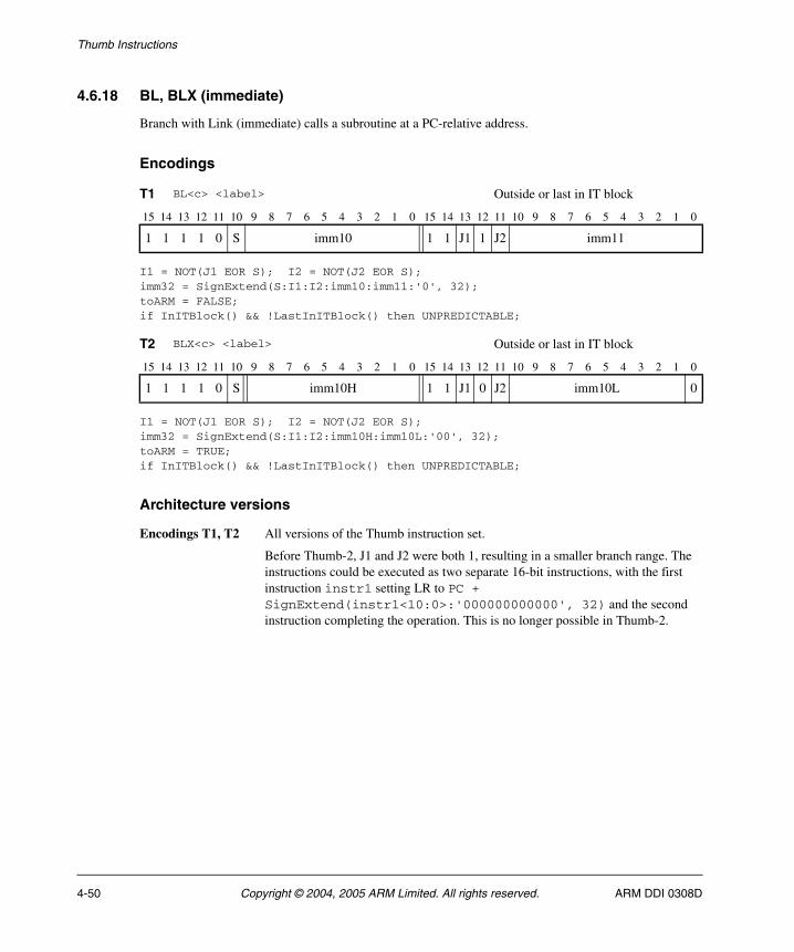
Thumb Instructions
4.6.18 BL, BLX (immediate)
Branch with Link (immediate) calls a subroutine at a PC-relative address.
Encodings
I1 = NOT(J1 EOR S); I2 = NOT(J2 EOR S);imm32 = SignExtend(S:I1:I2:imm10:imm11:'0', 32);toARM = FALSE;if InITBlock() && !LastInITBlock() then UNPREDICTABLE;
I1 = NOT(J1 EOR S); I2 = NOT(J2 EOR S);imm32 = SignExtend(S:I1:I2:imm10H:imm10L:'00', 32);toARM = TRUE;if InITBlock() && !LastInITBlock() then UNPREDICTABLE;
Architecture versions
Encodings T1, T2 All versions of the Thumb instruction set.
Before Thumb-2, J1 and J2 were both 1, resulting in a smaller branch range. The instructions could be executed as two separate 16-bit instructions, with the first instruction instr1 setting LR to PC + SignExtend(instr1<10:0>:'000000000000', 32) and the second instruction completing the operation. This is no longer possible in Thumb-2.
T1 BL<c> <label> Outside or last in IT block
15 14 13 12 11 10 9 8 7 6 5 4 3 2 1 0 15 14 13 12 11 10 9 8 7 6 5 4 3 2 1 0
1 1 1 1 0 S imm10 1 1 J1 1 J2 imm11
T2 BLX<c> <label> Outside or last in IT block
15 14 13 12 11 10 9 8 7 6 5 4 3 2 1 0 15 14 13 12 11 10 9 8 7 6 5 4 3 2 1 0
1 1 1 1 0 S imm10H 1 1 J1 0 J2 imm10L 0
4-50 Copyright © 2004, 2005 ARM Limited. All rights reserved. ARM DDI 0308D
Thumb Instructions
Assembler syntax
BL{X}<c><q> <label>
where:
<c><q> See Standard assembler syntax fields on page 4-6.
X If present, specifies a change to the ARM instruction set. If X is omitted, the processor remains in Thumb state.
<label> Specifies the label of the instruction that is to be branched to.
For BL (encoding T1), the assembler calculates the required value of the offset from the PC value of the BL instruction to this label, then selects an encoding that will set imm32 to that offset. Allowed offsets are even numbers in the range -16777216 to 16777214.
For BLX (encoding T2), the assembler calculates the required value of the offset from the Align(PC,4) value of the BLX instruction to this label, then selects an encoding that will set imm32 to that offset. Allowed offsets are multiples of 4 in the range -16777216 to 16777212.
Operation
if ConditionPassed() then EncodingSpecificOperations(); next_instr_addr = PC; LR = next_instr_addr<31:1> : '1'; if toARM then SelectInstrSet(InstrSet_ARM); BranchWritePC(Align(PC,4) + imm32); else SelectInstrSet(InstrSet_Thumb); BranchWritePC(PC + imm32);
Exceptions
None.
ARM DDI 0308D Copyright © 2004, 2005 ARM Limited. All rights reserved. 4-51
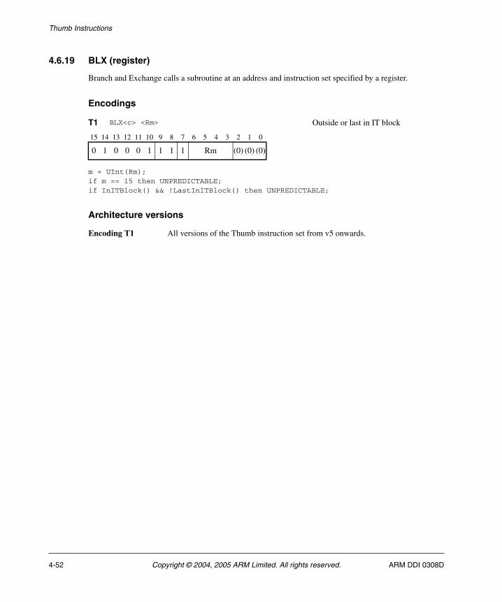
Thumb Instructions
4.6.19 BLX (register)
Branch and Exchange calls a subroutine at an address and instruction set specified by a register.
Encodings
m = UInt(Rm);if m == 15 then UNPREDICTABLE;if InITBlock() && !LastInITBlock() then UNPREDICTABLE;
Architecture versions
Encoding T1 All versions of the Thumb instruction set from v5 onwards.
T1 BLX<c> <Rm> Outside or last in IT block
15 14 13 12 11 10 9 8 7 6 5 4 3 2 1 0
0 1 0 0 0 1 1 1 1 Rm (0) (0) (0)
4-52 Copyright © 2004, 2005 ARM Limited. All rights reserved. ARM DDI 0308D
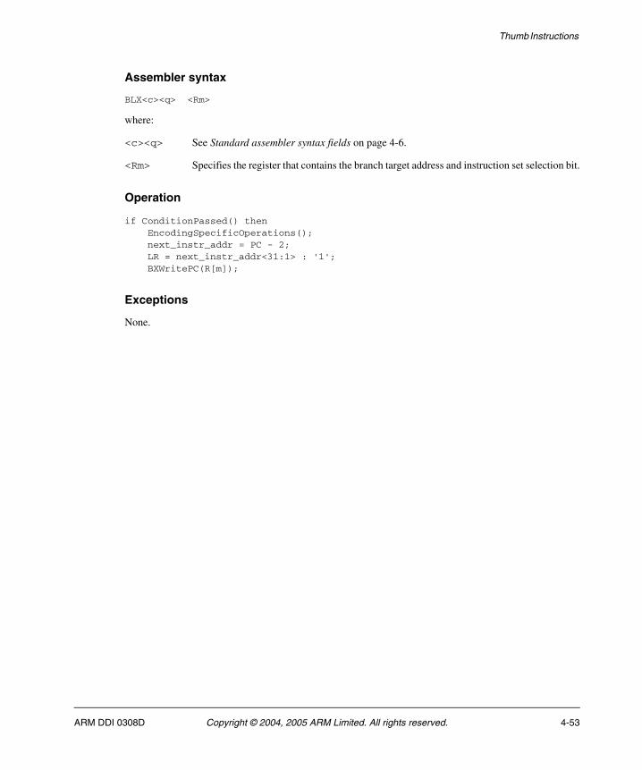
Thumb Instructions
Assembler syntax
BLX<c><q> <Rm>
where:
<c><q> See Standard assembler syntax fields on page 4-6.
<Rm> Specifies the register that contains the branch target address and instruction set selection bit.
Operation
if ConditionPassed() then EncodingSpecificOperations(); next_instr_addr = PC - 2; LR = next_instr_addr<31:1> : '1'; BXWritePC(R[m]);
Exceptions
None.
ARM DDI 0308D Copyright © 2004, 2005 ARM Limited. All rights reserved. 4-53

Thumb Instructions
4.6.20 BX
Branch and Exchange causes a branch to an address and instruction set specified by a register.
Encodings
m = UInt(Rm);if InITBlock() && !LastInITBlock() then UNPREDICTABLE;
Architecture versions
Encoding T1 All versions of the Thumb instruction set.
T1 BX<c> <Rm> Outside or last in IT block
15 14 13 12 11 10 9 8 7 6 5 4 3 2 1 0
0 1 0 0 0 1 1 1 0 Rm (0) (0) (0)
4-54 Copyright © 2004, 2005 ARM Limited. All rights reserved. ARM DDI 0308D
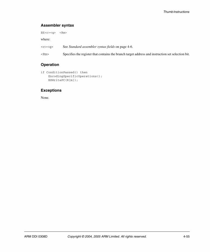
Thumb Instructions
Assembler syntax
BX<c><q> <Rm>
where:
<c><q> See Standard assembler syntax fields on page 4-6.
<Rm> Specifies the register that contains the branch target address and instruction set selection bit.
Operation
if ConditionPassed() then EncodingSpecificOperations(); BXWritePC(R[m]);
Exceptions
None.
ARM DDI 0308D Copyright © 2004, 2005 ARM Limited. All rights reserved. 4-55
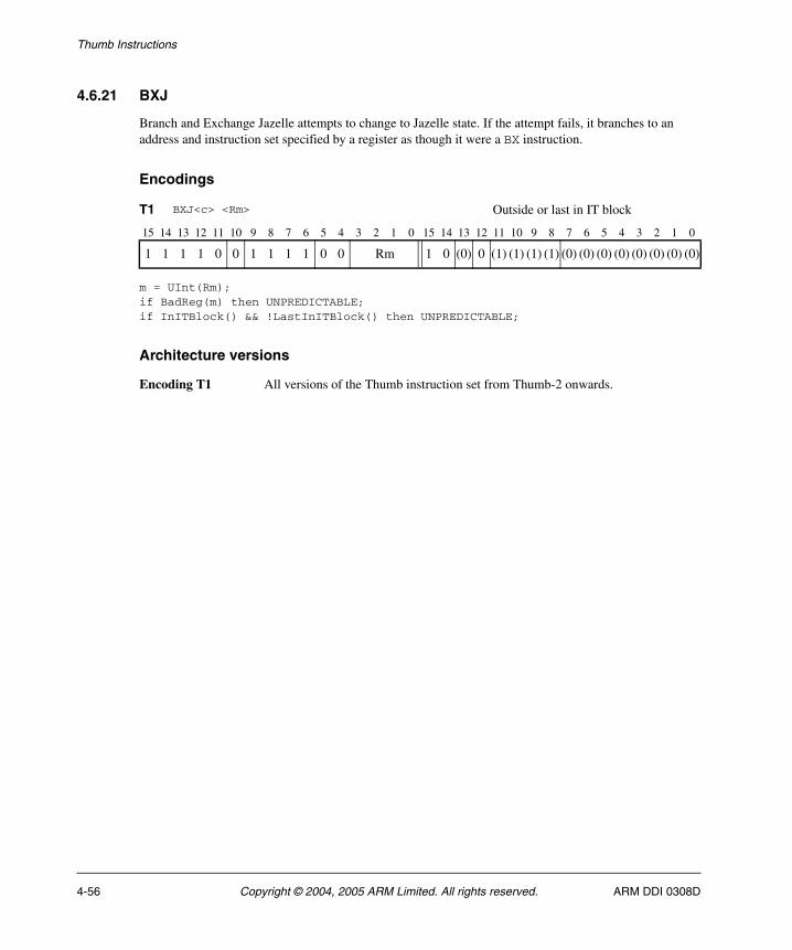
Thumb Instructions
4.6.21 BXJ
Branch and Exchange Jazelle attempts to change to Jazelle state. If the attempt fails, it branches to an address and instruction set specified by a register as though it were a BX instruction.
Encodings
m = UInt(Rm);if BadReg(m) then UNPREDICTABLE;if InITBlock() && !LastInITBlock() then UNPREDICTABLE;
Architecture versions
Encoding T1 All versions of the Thumb instruction set from Thumb-2 onwards.
T1 BXJ<c> <Rm> Outside or last in IT block
15 14 13 12 11 10 9 8 7 6 5 4 3 2 1 0 15 14 13 12 11 10 9 8 7 6 5 4 3 2 1 0
1 1 1 1 0 0 1 1 1 1 0 0 Rm 1 0 (0) 0 (1) (1) (1) (1) (0) (0) (0) (0) (0) (0) (0) (0)
4-56 Copyright © 2004, 2005 ARM Limited. All rights reserved. ARM DDI 0308D
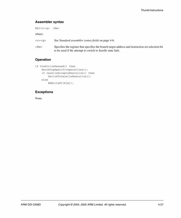
Thumb Instructions
Assembler syntax
BXJ<c><q> <Rm>
where:
<c><q> See Standard assembler syntax fields on page 4-6.
<Rm> Specifies the register that specifies the branch target address and instruction set selection bit to be used if the attempt to switch to Jazelle state fails.
Operation
if ConditionPassed() then EncodingSpecificOperations(); if JazelleAcceptsExecution() then SwitchToJazelleExecution(); else BXWritePC(R[m]);
Exceptions
None.
ARM DDI 0308D Copyright © 2004, 2005 ARM Limited. All rights reserved. 4-57
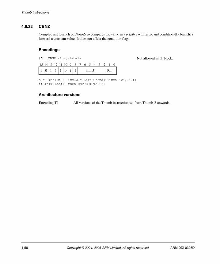
Thumb Instructions
4.6.22 CBNZ
Compare and Branch on Non-Zero compares the value in a register with zero, and conditionally branches forward a constant value. It does not affect the condition flags.
Encodings
n = UInt(Rn); imm32 = ZeroExtend(i:imm5:'0', 32);if InITBlock() then UNPREDICTABLE;
Architecture versions
Encoding T1 All versions of the Thumb instruction set from Thumb-2 onwards.
T1 CBNZ <Rn>,<label> Not allowed in IT block.
15 14 13 12 11 10 9 8 7 6 5 4 3 2 1 0
1 0 1 1 1 0 i 1 imm5 Rn
4-58 Copyright © 2004, 2005 ARM Limited. All rights reserved. ARM DDI 0308D

Thumb Instructions
Assembler syntax
CBNZ<q> <Rn>, <label>
where:
<q> See Standard assembler syntax fields on page 4-6.
<Rn> Specifies the register that contains the first operand.
<label> Specifies the label of the instruction that is to be branched to. The assembler calculates the required value of the offset from the PC value of the CBNZ instruction to this label, then selects an encoding that will set imm32 to that offset. Allowed offsets are even numbers in the range 0 to 126.
Operation
EncodingSpecificOperations();if IsZeroBit(R[n]) == '0' then BranchWritePC(PC + imm32);
Exceptions
None.
ARM DDI 0308D Copyright © 2004, 2005 ARM Limited. All rights reserved. 4-59
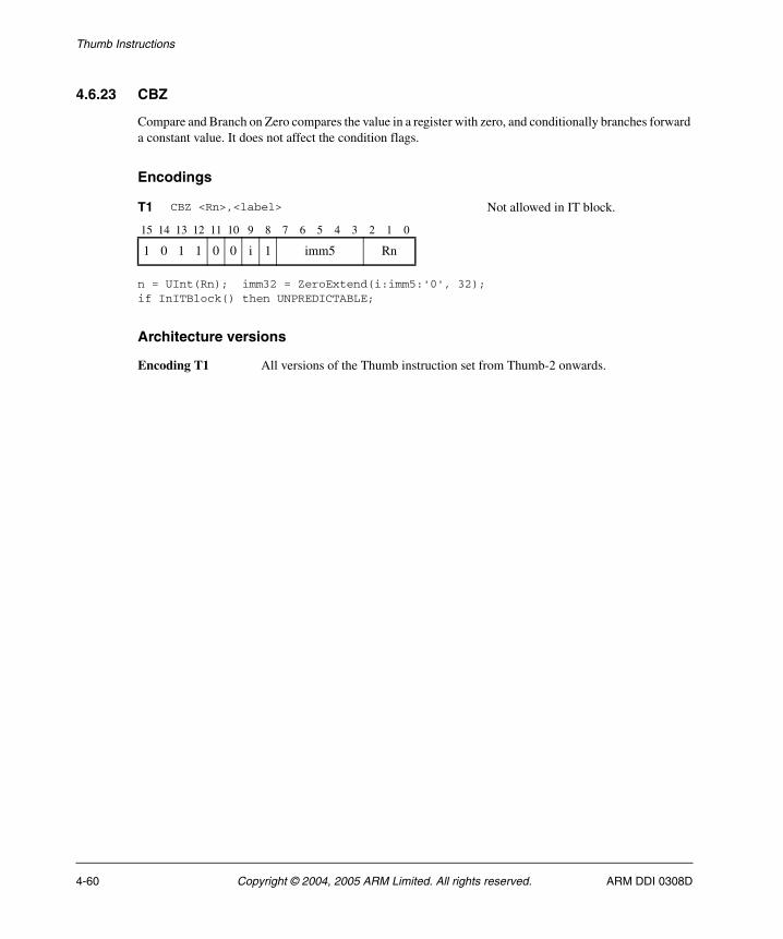
Thumb Instructions
4.6.23 CBZ
Compare and Branch on Zero compares the value in a register with zero, and conditionally branches forward a constant value. It does not affect the condition flags.
Encodings
n = UInt(Rn); imm32 = ZeroExtend(i:imm5:'0', 32);if InITBlock() then UNPREDICTABLE;
Architecture versions
Encoding T1 All versions of the Thumb instruction set from Thumb-2 onwards.
T1 CBZ <Rn>,<label> Not allowed in IT block.
15 14 13 12 11 10 9 8 7 6 5 4 3 2 1 0
1 0 1 1 0 0 i 1 imm5 Rn
4-60 Copyright © 2004, 2005 ARM Limited. All rights reserved. ARM DDI 0308D
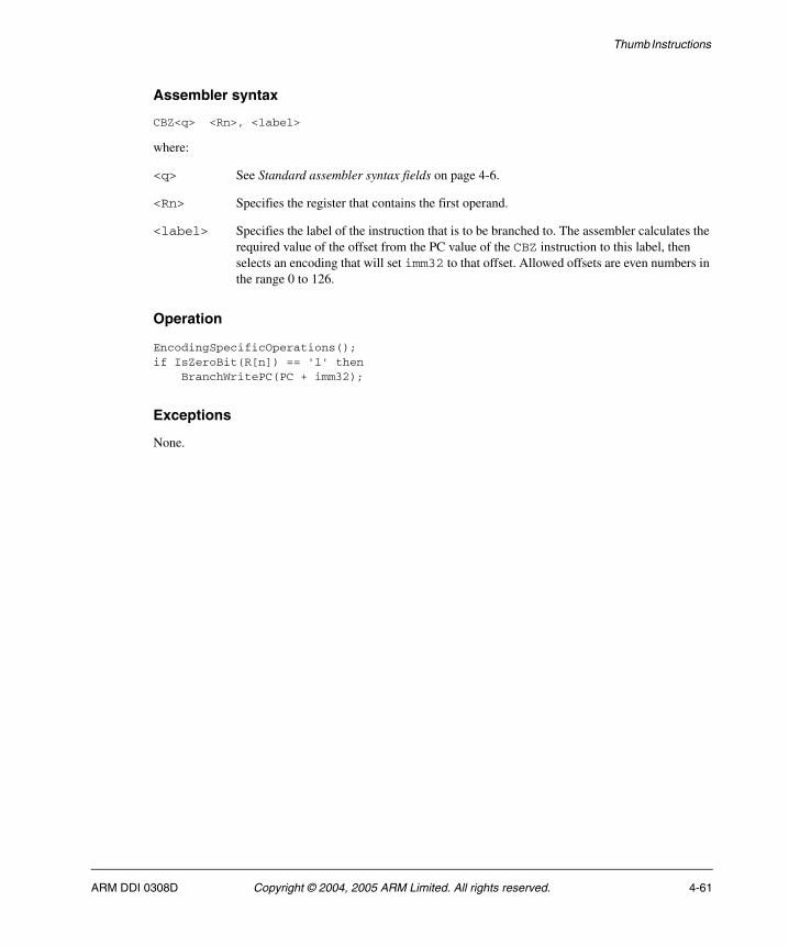
Thumb Instructions
Assembler syntax
CBZ<q> <Rn>, <label>
where:
<q> See Standard assembler syntax fields on page 4-6.
<Rn> Specifies the register that contains the first operand.
<label> Specifies the label of the instruction that is to be branched to. The assembler calculates the required value of the offset from the PC value of the CBZ instruction to this label, then selects an encoding that will set imm32 to that offset. Allowed offsets are even numbers in the range 0 to 126.
Operation
EncodingSpecificOperations();if IsZeroBit(R[n]) == '1' then BranchWritePC(PC + imm32);
Exceptions
None.
ARM DDI 0308D Copyright © 2004, 2005 ARM Limited. All rights reserved. 4-61
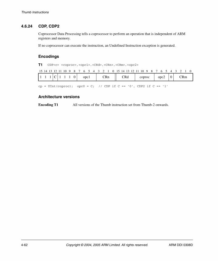
Thumb Instructions
4.6.24 CDP, CDP2
Coprocessor Data Processing tells a coprocessor to perform an operation that is independent of ARM registers and memory.
If no coprocessor can execute the instruction, an Undefined Instruction exception is generated.
Encodings
cp = UInt(coproc); opc0 = C; // CDP if C == '0', CDP2 if C == '1'
Architecture versions
Encoding T1 All versions of the Thumb instruction set from Thumb-2 onwards.
T1 CDP<c> <coproc>,<opc1>,<CRd>,<CRn>,<CRm>,<opc2>
15 14 13 12 11 10 9 8 7 6 5 4 3 2 1 0 15 14 13 12 11 10 9 8 7 6 5 4 3 2 1 0
1 1 1 C 1 1 1 0 opc1 CRn CRd coproc opc2 0 CRm
4-62 Copyright © 2004, 2005 ARM Limited. All rights reserved. ARM DDI 0308D
Thumb Instructions
Assembler syntax
CDP{2}<c><q> <coproc>, #<opc1>, <CRd>, <CRn>, <CRm> {,#<opc2>}
where:
2 If specified, selects the C == 1 form of the encoding. If omitted, selects the C == 0 form.
<c><q> See Standard assembler syntax fields on page 4-6.
<coproc> Specifies the name of the coprocessor, and causes the corresponding coprocessor number to be placed in the cp_num field of the instruction. The standard generic coprocessor names are p0, p1, ..., p15.
<opc1> Is a coprocessor-specific opcode, in the range 0 to 15.
<CRd> Specifies the destination coprocessor register for the instruction.
<CRn> Specifies the coprocessor register that contains the first operand.
<CRm> Specifies the coprocessor register that contains the second operand.
<opc2> Is a coprocessor-specific opcode in the range 0 to 7. If it is omitted, <opc2> is assumed to be 0.
Operation
if ConditionPassed() then EncodingSpecificOperations(); if !Coproc_Accepted(cp, ThisInstr()) then RaiseCoprocessorException(); else Coproc_InternalOperation(cp, ThisInstr());
Exceptions
Undefined Instruction.
Notes
Coprocessor fields Only instruction bits[31:24], bits[11:8], and bit[4] are architecturally defined. The remaining fields are recommendations.
ARM DDI 0308D Copyright © 2004, 2005 ARM Limited. All rights reserved. 4-63
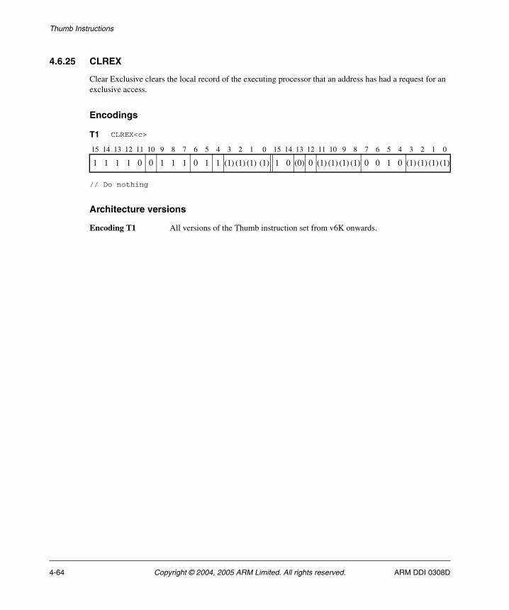
Thumb Instructions
4.6.25 CLREX
Clear Exclusive clears the local record of the executing processor that an address has had a request for an exclusive access.
Encodings
// Do nothing
Architecture versions
Encoding T1 All versions of the Thumb instruction set from v6K onwards.
T1 CLREX<c>
15 14 13 12 11 10 9 8 7 6 5 4 3 2 1 0 15 14 13 12 11 10 9 8 7 6 5 4 3 2 1 0
1 1 1 1 0 0 1 1 1 0 1 1 (1) (1) (1) (1) 1 0 (0) 0 (1) (1) (1) (1) 0 0 1 0 (1) (1) (1) (1)
4-64 Copyright © 2004, 2005 ARM Limited. All rights reserved. ARM DDI 0308D
Thumb Instructions
Assembler syntax
CLREX<c><q>
where:
<c><q> See Standard assembler syntax fields on page 4-6.
Operation
if ConditionPassed() then EncodingSpecificOperations(); ClearExclusiveMonitors();
Exceptions
None.
ARM DDI 0308D Copyright © 2004, 2005 ARM Limited. All rights reserved. 4-65
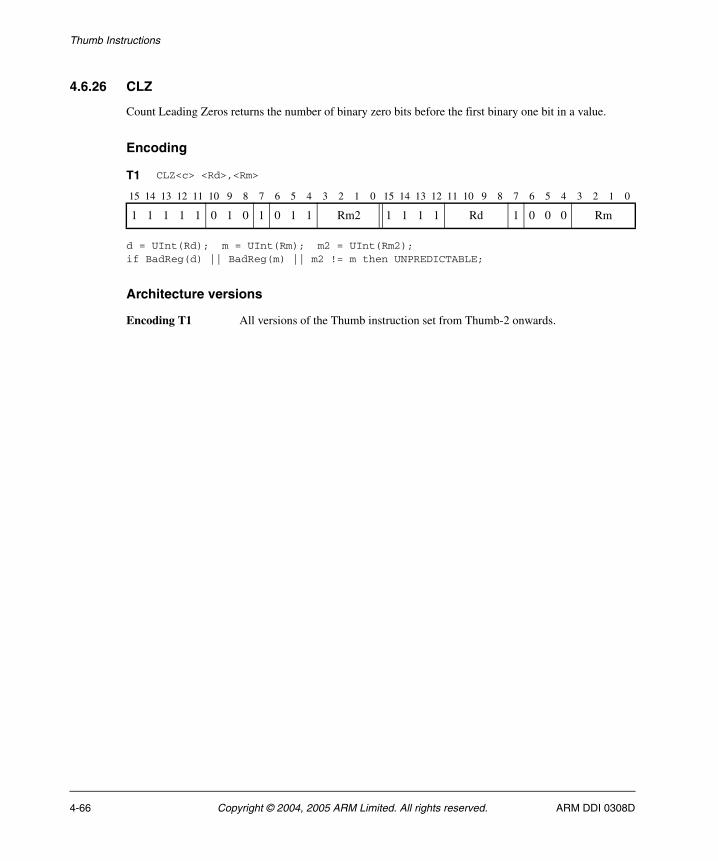
Thumb Instructions
4.6.26 CLZ
Count Leading Zeros returns the number of binary zero bits before the first binary one bit in a value.
Encoding
d = UInt(Rd); m = UInt(Rm); m2 = UInt(Rm2);if BadReg(d) || BadReg(m) || m2 != m then UNPREDICTABLE;
Architecture versions
Encoding T1 All versions of the Thumb instruction set from Thumb-2 onwards.
T1 CLZ<c> <Rd>,<Rm>
15 14 13 12 11 10 9 8 7 6 5 4 3 2 1 0 15 14 13 12 11 10 9 8 7 6 5 4 3 2 1 0
1 1 1 1 1 0 1 0 1 0 1 1 Rm2 1 1 1 1 Rd 1 0 0 0 Rm
4-66 Copyright © 2004, 2005 ARM Limited. All rights reserved. ARM DDI 0308D
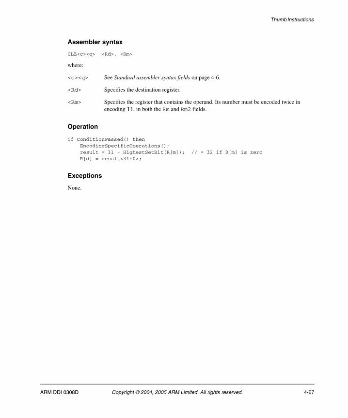
Thumb Instructions
Assembler syntax
CLZ<c><q> <Rd>, <Rm>
where:
<c><q> See Standard assembler syntax fields on page 4-6.
<Rd> Specifies the destination register.
<Rm> Specifies the register that contains the operand. Its number must be encoded twice in encoding T1, in both the Rm and Rm2 fields.
Operation
if ConditionPassed() then EncodingSpecificOperations(); result = 31 - HighestSetBit(R[m]); // = 32 if R[m] is zero R[d] = result<31:0>;
Exceptions
None.
ARM DDI 0308D Copyright © 2004, 2005 ARM Limited. All rights reserved. 4-67
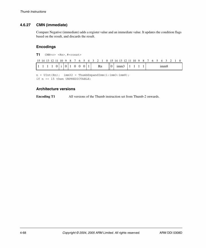
Thumb Instructions
4.6.27 CMN (immediate)
Compare Negative (immediate) adds a register value and an immediate value. It updates the condition flags based on the result, and discards the result.
Encodings
n = UInt(Rn); imm32 = ThumbExpandImm(i:imm3:imm8);if n == 15 then UNPREDICTABLE;
Architecture versions
Encoding T1 All versions of the Thumb instruction set from Thumb-2 onwards.
T1 CMN<c> <Rn>,#<const>
15 14 13 12 11 10 9 8 7 6 5 4 3 2 1 0 15 14 13 12 11 10 9 8 7 6 5 4 3 2 1 0
1 1 1 1 0 i 0 1 0 0 0 1 Rn 0 imm3 1 1 1 1 imm8
4-68 Copyright © 2004, 2005 ARM Limited. All rights reserved. ARM DDI 0308D
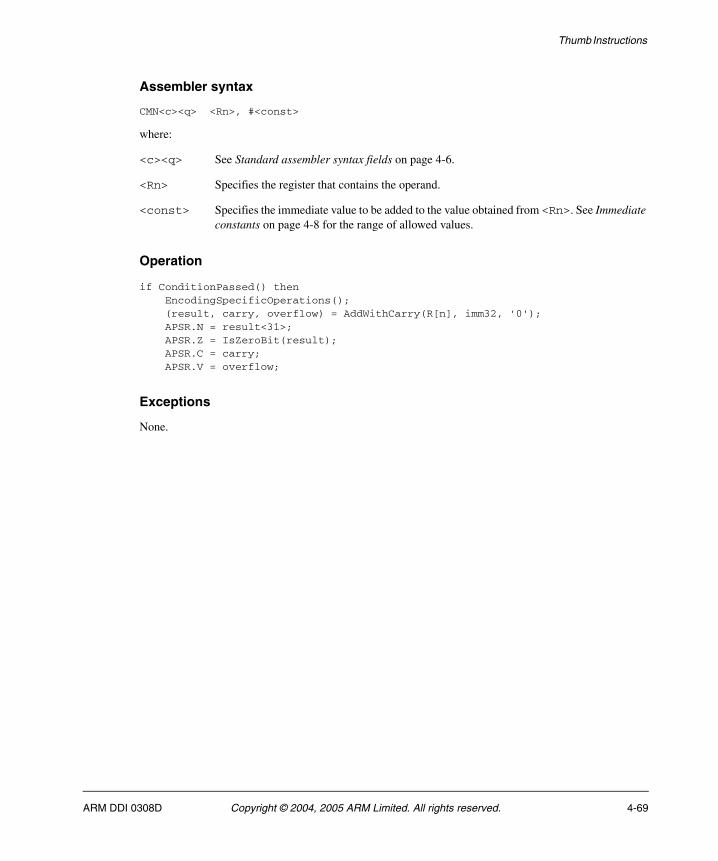
Thumb Instructions
Assembler syntax
CMN<c><q> <Rn>, #<const>
where:
<c><q> See Standard assembler syntax fields on page 4-6.
<Rn> Specifies the register that contains the operand.
<const> Specifies the immediate value to be added to the value obtained from <Rn>. See Immediate constants on page 4-8 for the range of allowed values.
Operation
if ConditionPassed() then EncodingSpecificOperations(); (result, carry, overflow) = AddWithCarry(R[n], imm32, '0'); APSR.N = result<31>; APSR.Z = IsZeroBit(result); APSR.C = carry; APSR.V = overflow;
Exceptions
None.
ARM DDI 0308D Copyright © 2004, 2005 ARM Limited. All rights reserved. 4-69
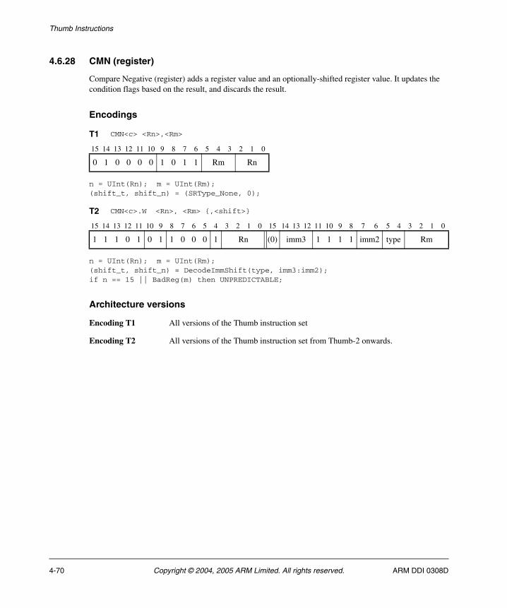
Thumb Instructions
4.6.28 CMN (register)
Compare Negative (register) adds a register value and an optionally-shifted register value. It updates the condition flags based on the result, and discards the result.
Encodings
n = UInt(Rn); m = UInt(Rm);(shift_t, shift_n) = (SRType_None, 0);
n = UInt(Rn); m = UInt(Rm);(shift_t, shift_n) = DecodeImmShift(type, imm3:imm2);if n == 15 || BadReg(m) then UNPREDICTABLE;
Architecture versions
Encoding T1 All versions of the Thumb instruction set
Encoding T2 All versions of the Thumb instruction set from Thumb-2 onwards.
T1 CMN<c> <Rn>,<Rm>
15 14 13 12 11 10 9 8 7 6 5 4 3 2 1 0
0 1 0 0 0 0 1 0 1 1 Rm Rn
T2 CMN<c>.W <Rn>, <Rm> {,<shift>}
15 14 13 12 11 10 9 8 7 6 5 4 3 2 1 0 15 14 13 12 11 10 9 8 7 6 5 4 3 2 1 0
1 1 1 0 1 0 1 1 0 0 0 1 Rn (0) imm3 1 1 1 1 imm2 type Rm
4-70 Copyright © 2004, 2005 ARM Limited. All rights reserved. ARM DDI 0308D
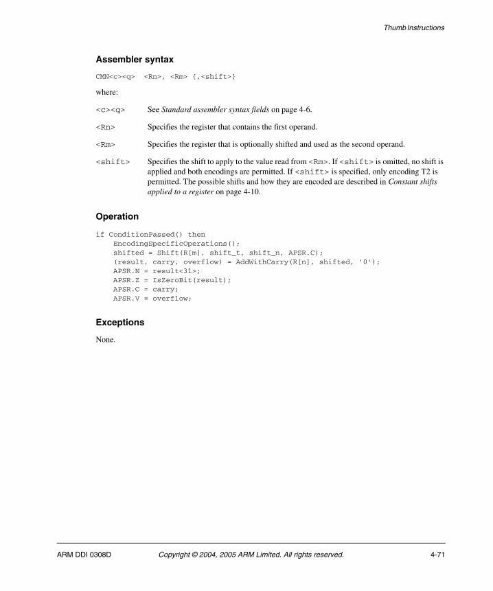
Thumb Instructions
Assembler syntax
CMN<c><q> <Rn>, <Rm> {,<shift>}
where:
<c><q> See Standard assembler syntax fields on page 4-6.
<Rn> Specifies the register that contains the first operand.
<Rm> Specifies the register that is optionally shifted and used as the second operand.
<shift> Specifies the shift to apply to the value read from <Rm>. If <shift> is omitted, no shift is applied and both encodings are permitted. If <shift> is specified, only encoding T2 is permitted. The possible shifts and how they are encoded are described in Constant shifts applied to a register on page 4-10.
Operation
if ConditionPassed() then EncodingSpecificOperations(); shifted = Shift(R[m], shift_t, shift_n, APSR.C); (result, carry, overflow) = AddWithCarry(R[n], shifted, '0'); APSR.N = result<31>; APSR.Z = IsZeroBit(result); APSR.C = carry; APSR.V = overflow;
Exceptions
None.
ARM DDI 0308D Copyright © 2004, 2005 ARM Limited. All rights reserved. 4-71

Thumb Instructions
4.6.29 CMP (immediate)
Compare (immediate) subtracts an immediate value from a register value. It updates the condition flags based on the result, and discards the result.
Encodings
n = UInt(Rdn); imm32 = ZeroExtend(imm8, 32);
n = UInt(Rn); imm32 = ThumbExpandImm(i:imm3:imm8);if n == 15 then UNPREDICTABLE;
Architecture versions
Encoding T1 All versions of the Thumb instruction set.
Encoding T2 All versions of the Thumb instruction set from Thumb-2 onwards.
T1 CMP <Rn>,#<imm8>
15 14 13 12 11 10 9 8 7 6 5 4 3 2 1 0
0 0 1 0 1 Rn imm8
T2 CMP<c>.W <Rn>,#<const>
15 14 13 12 11 10 9 8 7 6 5 4 3 2 1 0 15 14 13 12 11 10 9 8 7 6 5 4 3 2 1 0
1 1 1 1 0 i 0 1 1 0 1 1 Rn 0 imm3 1 1 1 1 imm8
4-72 Copyright © 2004, 2005 ARM Limited. All rights reserved. ARM DDI 0308D
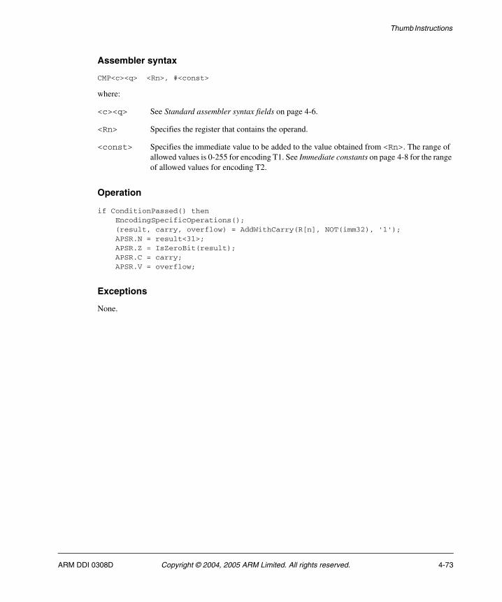
Thumb Instructions
Assembler syntax
CMP<c><q> <Rn>, #<const>
where:
<c><q> See Standard assembler syntax fields on page 4-6.
<Rn> Specifies the register that contains the operand.
<const> Specifies the immediate value to be added to the value obtained from <Rn>. The range of allowed values is 0-255 for encoding T1. See Immediate constants on page 4-8 for the range of allowed values for encoding T2.
Operation
if ConditionPassed() then EncodingSpecificOperations(); (result, carry, overflow) = AddWithCarry(R[n], NOT(imm32), '1'); APSR.N = result<31>; APSR.Z = IsZeroBit(result); APSR.C = carry; APSR.V = overflow;
Exceptions
None.
ARM DDI 0308D Copyright © 2004, 2005 ARM Limited. All rights reserved. 4-73
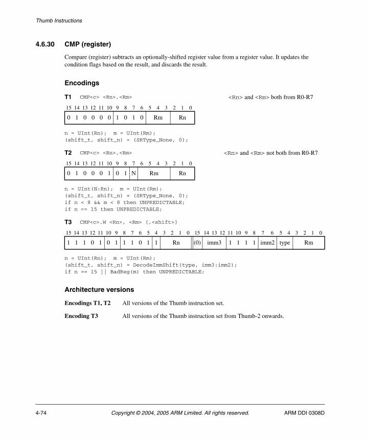
Thumb Instructions
4.6.30 CMP (register)
Compare (register) subtracts an optionally-shifted register value from a register value. It updates the condition flags based on the result, and discards the result.
Encodings
n = UInt(Rn); m = UInt(Rm);(shift_t, shift_n) = (SRType_None, 0);
n = UInt(N:Rn); m = UInt(Rm);(shift_t, shift_n) = (SRType_None, 0);if n < 8 && m < 8 then UNPREDICTABLE;if n == 15 then UNPREDICTABLE;
n = UInt(Rn); m = UInt(Rm);(shift_t, shift_n) = DecodeImmShift(type, imm3:imm2);if n == 15 || BadReg(m) then UNPREDICTABLE;
Architecture versions
Encodings T1, T2 All versions of the Thumb instruction set.
Encoding T3 All versions of the Thumb instruction set from Thumb-2 onwards.
T1 CMP<c> <Rn>,<Rm> <Rn> and <Rm> both from R0-R7
15 14 13 12 11 10 9 8 7 6 5 4 3 2 1 0
0 1 0 0 0 0 1 0 1 0 Rm Rn
T2 CMP<c> <Rn>,<Rm> <Rn> and <Rm> not both from R0-R7
15 14 13 12 11 10 9 8 7 6 5 4 3 2 1 0
0 1 0 0 0 1 0 1 N Rm Rn
T3 CMP<c>.W <Rn>, <Rm> {,<shift>}
15 14 13 12 11 10 9 8 7 6 5 4 3 2 1 0 15 14 13 12 11 10 9 8 7 6 5 4 3 2 1 0
1 1 1 0 1 0 1 1 1 0 1 1 Rn (0) imm3 1 1 1 1 imm2 type Rm
4-74 Copyright © 2004, 2005 ARM Limited. All rights reserved. ARM DDI 0308D
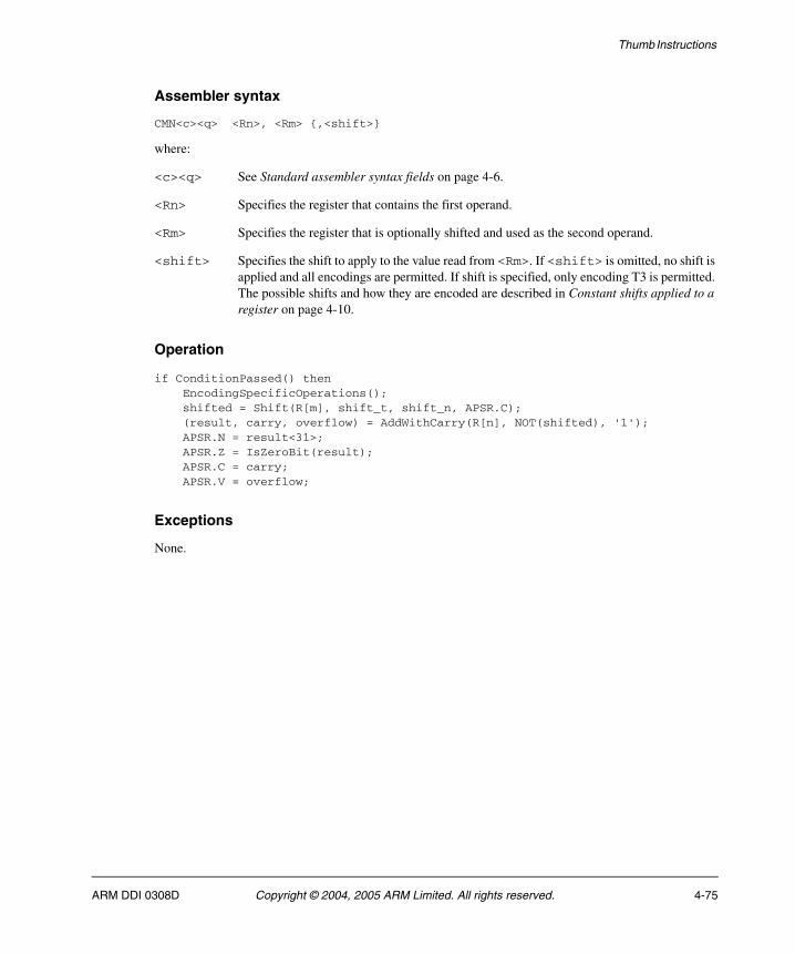
Thumb Instructions
Assembler syntax
CMN<c><q> <Rn>, <Rm> {,<shift>}
where:
<c><q> See Standard assembler syntax fields on page 4-6.
<Rn> Specifies the register that contains the first operand.
<Rm> Specifies the register that is optionally shifted and used as the second operand.
<shift> Specifies the shift to apply to the value read from <Rm>. If <shift> is omitted, no shift is applied and all encodings are permitted. If shift is specified, only encoding T3 is permitted. The possible shifts and how they are encoded are described in Constant shifts applied to a register on page 4-10.
Operation
if ConditionPassed() then EncodingSpecificOperations(); shifted = Shift(R[m], shift_t, shift_n, APSR.C); (result, carry, overflow) = AddWithCarry(R[n], NOT(shifted), '1'); APSR.N = result<31>; APSR.Z = IsZeroBit(result); APSR.C = carry; APSR.V = overflow;
Exceptions
None.
ARM DDI 0308D Copyright © 2004, 2005 ARM Limited. All rights reserved. 4-75
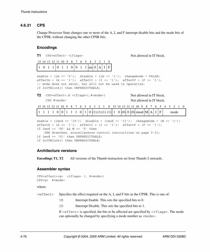
Thumb Instructions
4.6.31 CPS
Change Processor State changes one or more of the A, I, and F interrupt disable bits and the mode bits of the CPSR, without changing the other CPSR bits.
Encodings
enable = (im == '0'); disable = (im == '1'); changemode = FALSE;affectA = (A == '1'); affectI = (I == '1'); affectF = (F == '1');// mode does not exist, but will not be used in Operation.if InITBlock() then UNPREDICTABLE;
enable = (imod == '10'); disable = (imod == '11'); changemode = (M == '1');affectA = (A == '1'); affectI = (I == '1'); affectF = (F == '1');if imod == '00' && M == '0' then SEE Branches, miscellaneous control instructions on page 3-31;if imod == '01' then UNPREDICTABLE;if InITBlock() then UNPREDICTABLE;
Architecture versions
Encodings T1, T2 All versions of the Thumb instruction set from Thumb-2 onwards.
Assembler syntax
CPS<effect><q> <iflags> {, #<mode>}CPS<q> #<mode>
where:
<effect> Specifies the effect required on the A, I, and F bits in the CPSR. This is one of:
IE Interrupt Enable. This sets the specified bits to 0.
ID Interrupt Disable. This sets the specified bits to 1.
If <effect> is specified, the bits to be affected are specified by <iflags>. The mode can optionally be changed by specifying a mode number as <mode>.
T1 CPS<effect> <iflags> Not allowed in IT block.
15 14 13 12 11 10 9 8 7 6 5 4 3 2 1 0
1 0 1 1 0 1 1 0 0 1 1 im 0 A I F
T2 CPS<effect>.W <iflags>{,#<mode>} Not allowed in IT block.CPS #<mode> Not allowed in IT block.
15 14 13 12 11 10 9 8 7 6 5 4 3 2 1 0 15 14 13 12 11 10 9 8 7 6 5 4 3 2 1 0
1 1 1 1 0 0 1 1 1 0 1 0 (1) (1) (1) (1) 1 0 (0) 0 (0) imod M A I F mode
4-76 Copyright © 2004, 2005 ARM Limited. All rights reserved. ARM DDI 0308D

Thumb Instructions
If <effect> is not specified, then:
• <iflags> is not specified and interrupt settings are not changed
• <mode> specifies the new mode number.
<q> See Standard assembler syntax fields on page 4-6.
<iflags> Is a sequence of one or more of the following, specifying which interrupt disable flags are affected:
a Sets the A bit in the instruction, causing the specified effect on the CPSR A (imprecise data abort) bit.
i Sets the I bit in the instruction, causing the specified effect on the CPSR I (IRQ interrupt) bit.
f Sets the F bit in the instruction, causing the specified effect on the CPSR F (FIQ interrupt) bit.
<mode> Specifies the number of the mode to change to. If this option is omitted, no mode change occurs.
Operation
EncodingSpecificOperations();if CurrentModeIsPrivileged() then if enable then if affectA then CPSR.A = '0'; if affectI then CPSR.I = '0'; if affectF then CPSR.F = '0'; if disable then if affectA then CPSR.A = '1'; if affectI then CPSR.I = '1'; if affectF then CPSR.F = '1'; if changemode then CPSR.M[4:0] = mode;
Exceptions
None.
ARM DDI 0308D Copyright © 2004, 2005 ARM Limited. All rights reserved. 4-77
Thumb Instructions
4.6.32 CPY
Copy is a pre-UAL synonym for MOV (register).
4-78 Copyright © 2004, 2005 ARM Limited. All rights reserved. ARM DDI 0308D
Thumb Instructions
Assembler syntax
CPY <Rd>, <Rn>
This is equivalent to:
MOV <Rd>, <Rn>
Exceptions
None.
ARM DDI 0308D Copyright © 2004, 2005 ARM Limited. All rights reserved. 4-79
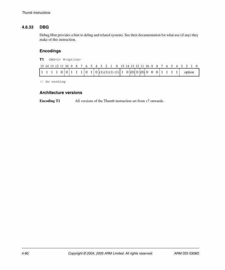
Thumb Instructions
4.6.33 DBG
Debug Hint provides a hint to debug and related systems. See their documentation for what use (if any) they make of this instruction.
Encodings
// Do nothing
Architecture versions
Encoding T1 All versions of the Thumb instruction set from v7 onwards.
T1 DBG<c> #<option>
15 14 13 12 11 10 9 8 7 6 5 4 3 2 1 0 15 14 13 12 11 10 9 8 7 6 5 4 3 2 1 0
1 1 1 1 0 0 1 1 1 0 1 0 (1) (1) (1) (1) 1 0 (0) 0 (0) 0 0 0 1 1 1 1 option
4-80 Copyright © 2004, 2005 ARM Limited. All rights reserved. ARM DDI 0308D
Thumb Instructions
Assembler syntax
DBG<c><q> #<option>
where:
<c><q> See Standard assembler syntax fields on page 4-6.
<option> Provides extra information about the hint, and is in the range 0 to 15.
Operation
if ConditionPassed() then EncodingSpecificOperations(); Hint_Debug(option);
Exceptions
None.
ARM DDI 0308D Copyright © 2004, 2005 ARM Limited. All rights reserved. 4-81
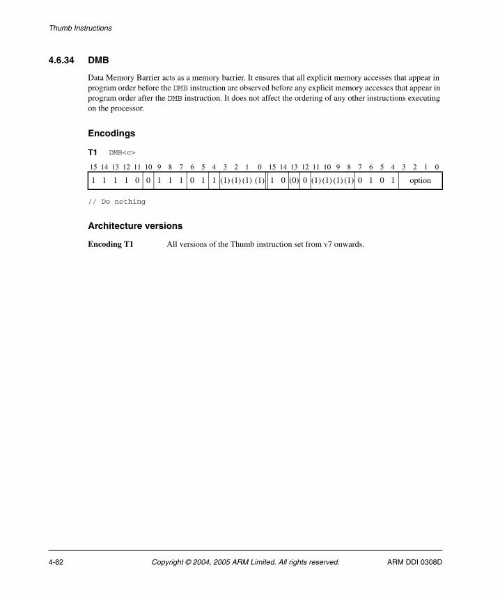
Thumb Instructions
4.6.34 DMB
Data Memory Barrier acts as a memory barrier. It ensures that all explicit memory accesses that appear in program order before the DMB instruction are observed before any explicit memory accesses that appear in program order after the DMB instruction. It does not affect the ordering of any other instructions executing on the processor.
Encodings
// Do nothing
Architecture versions
Encoding T1 All versions of the Thumb instruction set from v7 onwards.
T1 DMB<c>
15 14 13 12 11 10 9 8 7 6 5 4 3 2 1 0 15 14 13 12 11 10 9 8 7 6 5 4 3 2 1 0
1 1 1 1 0 0 1 1 1 0 1 1 (1) (1) (1) (1) 1 0 (0) 0 (1) (1) (1) (1) 0 1 0 1 option
4-82 Copyright © 2004, 2005 ARM Limited. All rights reserved. ARM DDI 0308D
Thumb Instructions
Assembler syntax
DMB<c><q> {<opt>}
where:
<c><q> See Standard assembler syntax fields on page 4-6.
<opt> Specifies an optional limitation on the DMB operation. Allowed values are:
SY Full system DMB operation, encoded as option == '1111'. Can be omitted.
All other encodings of option are RESERVED. The corresponding instructions execute as full system DMB operations, but should not be relied upon by software.
Operation
if ConditionPassed() then EncodingSpecificOperations(); DataMemoryBarrier(option);
Exceptions
None.
ARM DDI 0308D Copyright © 2004, 2005 ARM Limited. All rights reserved. 4-83
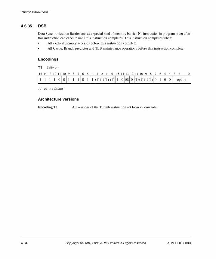
Thumb Instructions
4.6.35 DSB
Data Synchronization Barrier acts as a special kind of memory barrier. No instruction in program order after this instruction can execute until this instruction completes. This instruction completes when:
• All explicit memory accesses before this instruction complete.
• All Cache, Branch predictor and TLB maintenance operations before this instruction complete.
Encodings
// Do nothing
Architecture versions
Encoding T1 All versions of the Thumb instruction set from v7 onwards.
T1 DSB<c>
15 14 13 12 11 10 9 8 7 6 5 4 3 2 1 0 15 14 13 12 11 10 9 8 7 6 5 4 3 2 1 0
1 1 1 1 0 0 1 1 1 0 1 1 (1) (1) (1) (1) 1 0 (0) 0 (1) (1) (1) (1) 0 1 0 0 option
4-84 Copyright © 2004, 2005 ARM Limited. All rights reserved. ARM DDI 0308D
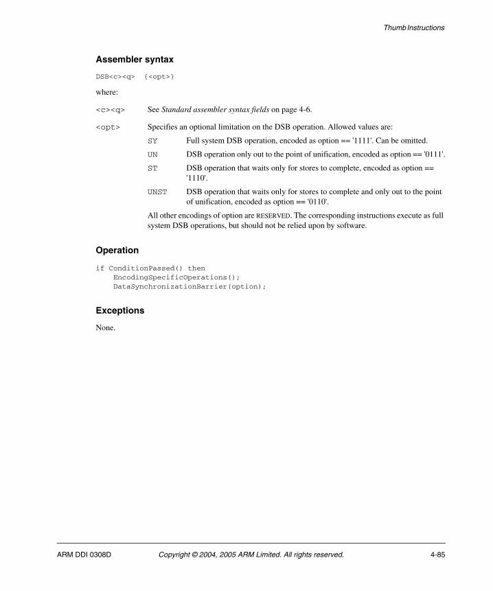
Thumb Instructions
Assembler syntax
DSB<c><q> {<opt>}
where:
<c><q> See Standard assembler syntax fields on page 4-6.
<opt> Specifies an optional limitation on the DSB operation. Allowed values are:
SY Full system DSB operation, encoded as option == '1111'. Can be omitted.
UN DSB operation only out to the point of unification, encoded as option == '0111'.
ST DSB operation that waits only for stores to complete, encoded as option == '1110'.
UNST DSB operation that waits only for stores to complete and only out to the point of unification, encoded as option == '0110'.
All other encodings of option are RESERVED. The corresponding instructions execute as full system DSB operations, but should not be relied upon by software.
Operation
if ConditionPassed() then EncodingSpecificOperations(); DataSynchronizationBarrier(option);
Exceptions
None.
ARM DDI 0308D Copyright © 2004, 2005 ARM Limited. All rights reserved. 4-85
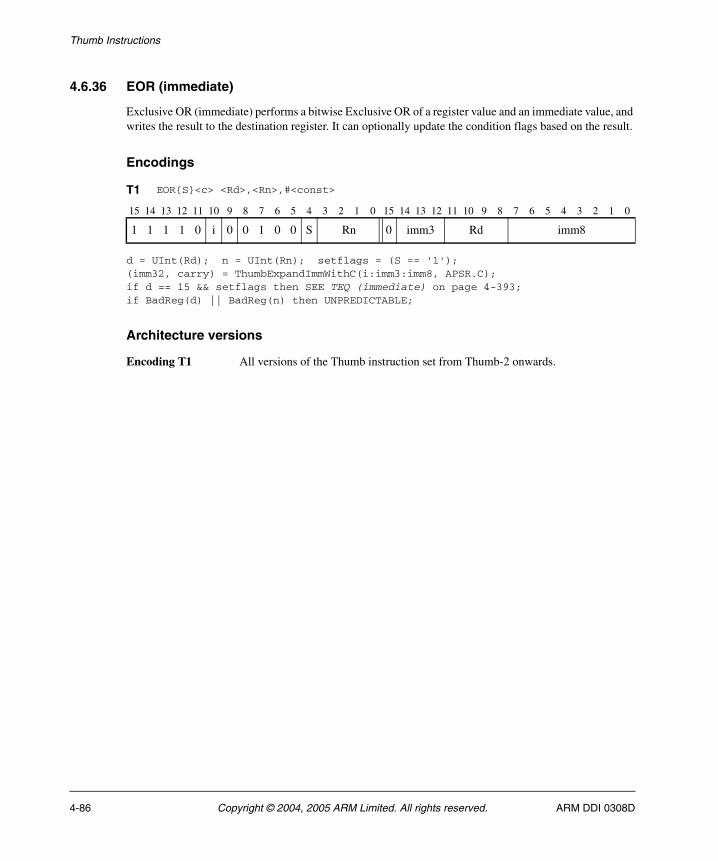
Thumb Instructions
4.6.36 EOR (immediate)
Exclusive OR (immediate) performs a bitwise Exclusive OR of a register value and an immediate value, and writes the result to the destination register. It can optionally update the condition flags based on the result.
Encodings
d = UInt(Rd); n = UInt(Rn); setflags = (S == '1');(imm32, carry) = ThumbExpandImmWithC(i:imm3:imm8, APSR.C);if d == 15 && setflags then SEE TEQ (immediate) on page 4-393;if BadReg(d) || BadReg(n) then UNPREDICTABLE;
Architecture versions
Encoding T1 All versions of the Thumb instruction set from Thumb-2 onwards.
T1 EOR{S}<c> <Rd>,<Rn>,#<const>
15 14 13 12 11 10 9 8 7 6 5 4 3 2 1 0 15 14 13 12 11 10 9 8 7 6 5 4 3 2 1 0
1 1 1 1 0 i 0 0 1 0 0 S Rn 0 imm3 Rd imm8
4-86 Copyright © 2004, 2005 ARM Limited. All rights reserved. ARM DDI 0308D

Thumb Instructions
Assembler syntax
EOR{S}<c><q> {<Rd>,} <Rn>, #<const>
where:
S If present, specifies that the instruction updates the flags. Otherwise, the instruction does not update the flags.
<c><q> See Standard assembler syntax fields on page 4-6.
<Rd> Specifies the destination register. If <Rd> is omitted, this register is the same as <Rn>.
<Rn> Specifies the register that contains the operand.
<const> Specifies the immediate value to be added to the value obtained from <Rn>. See Immediate constants on page 4-8 for the range of allowed values.
The pre-UAL syntax EOR<c>S is equivalent to EORS<c>.
Operation
if ConditionPassed() then EncodingSpecificOperations(); result = R[n] EOR imm32; R[d] = result; if setflags then APSR.N = result<31>; APSR.Z = IsZeroBit(result); APSR.C = carry; // APSR.V unchanged
Exceptions
None.
ARM DDI 0308D Copyright © 2004, 2005 ARM Limited. All rights reserved. 4-87
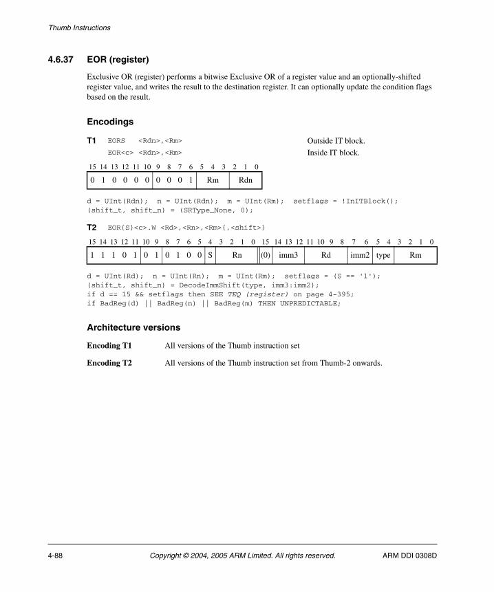
Thumb Instructions
4.6.37 EOR (register)
Exclusive OR (register) performs a bitwise Exclusive OR of a register value and an optionally-shifted register value, and writes the result to the destination register. It can optionally update the condition flags based on the result.
Encodings
d = UInt(Rdn); n = UInt(Rdn); m = UInt(Rm); setflags = !InITBlock();(shift_t, shift_n) = (SRType_None, 0);
d = UInt(Rd); n = UInt(Rn); m = UInt(Rm); setflags = (S == '1');(shift_t, shift_n) = DecodeImmShift(type, imm3:imm2);if d == 15 && setflags then SEE TEQ (register) on page 4-395;if BadReg(d) || BadReg(n) || BadReg(m) THEN UNPREDICTABLE;
Architecture versions
Encoding T1 All versions of the Thumb instruction set
Encoding T2 All versions of the Thumb instruction set from Thumb-2 onwards.
T1 EORS <Rdn>,<Rm> Outside IT block.EOR<c> <Rdn>,<Rm> Inside IT block.
15 14 13 12 11 10 9 8 7 6 5 4 3 2 1 0
0 1 0 0 0 0 0 0 0 1 Rm Rdn
T2 EOR{S}<c>.W <Rd>,<Rn>,<Rm>{,<shift>}
15 14 13 12 11 10 9 8 7 6 5 4 3 2 1 0 15 14 13 12 11 10 9 8 7 6 5 4 3 2 1 0
1 1 1 0 1 0 1 0 1 0 0 S Rn (0) imm3 Rd imm2 type Rm
4-88 Copyright © 2004, 2005 ARM Limited. All rights reserved. ARM DDI 0308D
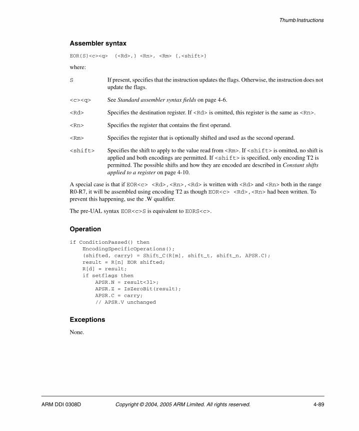
Thumb Instructions
Assembler syntax
EOR{S}<c><q> {<Rd>,} <Rn>, <Rm> {,<shift>}
where:
S If present, specifies that the instruction updates the flags. Otherwise, the instruction does not update the flags.
<c><q> See Standard assembler syntax fields on page 4-6.
<Rd> Specifies the destination register. If <Rd> is omitted, this register is the same as <Rn>.
<Rn> Specifies the register that contains the first operand.
<Rm> Specifies the register that is optionally shifted and used as the second operand.
<shift> Specifies the shift to apply to the value read from <Rm>. If <shift> is omitted, no shift is applied and both encodings are permitted. If <shift> is specified, only encoding T2 is permitted. The possible shifts and how they are encoded are described in Constant shifts applied to a register on page 4-10.
A special case is that if EOR<c> <Rd>,<Rn>,<Rd> is written with <Rd> and <Rn> both in the range R0-R7, it will be assembled using encoding T2 as though EOR<c> <Rd>,<Rn> had been written. To prevent this happening, use the .W qualifier.
The pre-UAL syntax EOR<c>S is equivalent to EORS<c>.
Operation
if ConditionPassed() then EncodingSpecificOperations(); (shifted, carry) = Shift_C(R[m], shift_t, shift_n, APSR.C); result = R[n] EOR shifted; R[d] = result; if setflags then APSR.N = result<31>; APSR.Z = IsZeroBit(result); APSR.C = carry; // APSR.V unchanged
Exceptions
None.
ARM DDI 0308D Copyright © 2004, 2005 ARM Limited. All rights reserved. 4-89
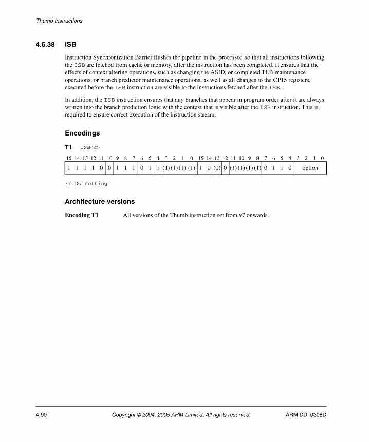
Thumb Instructions
4.6.38 ISB
Instruction Synchronization Barrier flushes the pipeline in the processor, so that all instructions following the ISB are fetched from cache or memory, after the instruction has been completed. It ensures that the effects of context altering operations, such as changing the ASID, or completed TLB maintenance operations, or branch predictor maintenance operations, as well as all changes to the CP15 registers, executed before the ISB instruction are visible to the instructions fetched after the ISB.
In addition, the ISB instruction ensures that any branches that appear in program order after it are always written into the branch prediction logic with the context that is visible after the ISB instruction. This is required to ensure correct execution of the instruction stream.
Encodings
// Do nothing
Architecture versions
Encoding T1 All versions of the Thumb instruction set from v7 onwards.
T1 ISB<c>
15 14 13 12 11 10 9 8 7 6 5 4 3 2 1 0 15 14 13 12 11 10 9 8 7 6 5 4 3 2 1 0
1 1 1 1 0 0 1 1 1 0 1 1 (1) (1) (1) (1) 1 0 (0) 0 (1) (1) (1) (1) 0 1 1 0 option
4-90 Copyright © 2004, 2005 ARM Limited. All rights reserved. ARM DDI 0308D
Thumb Instructions
Assembler syntax
ISB<c><q> {<opt>}
where:
<c><q> See Standard assembler syntax fields on page 4-6.
<opt> Specifies an optional limitation on the ISB operation. Allowed values are:
SY Full system ISB operation, encoded as option == '1111'. Can be omitted.
All other encodings of option are RESERVED. The corresponding instructions execute as full system ISB operations, but should not be relied upon by software.
Operation
if ConditionPassed() then EncodingSpecificOperations(); InstructionSynchronizationBarrier(option);
Exceptions
None.
ARM DDI 0308D Copyright © 2004, 2005 ARM Limited. All rights reserved. 4-91
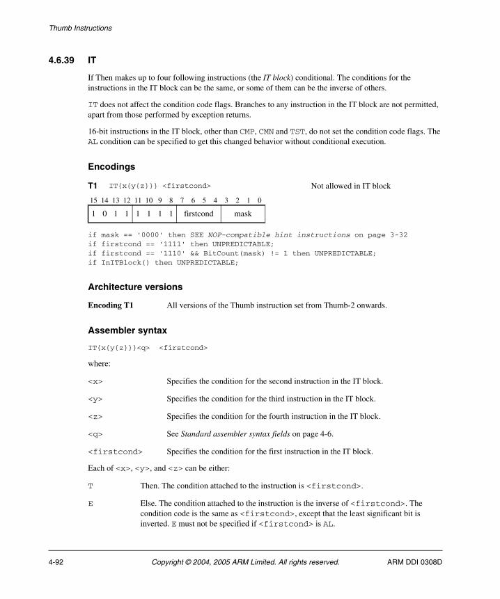
Thumb Instructions
4.6.39 IT
If Then makes up to four following instructions (the IT block) conditional. The conditions for the instructions in the IT block can be the same, or some of them can be the inverse of others.
IT does not affect the condition code flags. Branches to any instruction in the IT block are not permitted, apart from those performed by exception returns.
16-bit instructions in the IT block, other than CMP, CMN and TST, do not set the condition code flags. The AL condition can be specified to get this changed behavior without conditional execution.
Encodings
if mask == '0000' then SEE NOP-compatible hint instructions on page 3-32if firstcond == '1111' then UNPREDICTABLE; if firstcond == '1110' && BitCount(mask) != 1 then UNPREDICTABLE; if InITBlock() then UNPREDICTABLE;
Architecture versions
Encoding T1 All versions of the Thumb instruction set from Thumb-2 onwards.
Assembler syntax
IT{x{y{z}}}<q> <firstcond>
where:
<x> Specifies the condition for the second instruction in the IT block.
<y> Specifies the condition for the third instruction in the IT block.
<z> Specifies the condition for the fourth instruction in the IT block.
<q> See Standard assembler syntax fields on page 4-6.
<firstcond> Specifies the condition for the first instruction in the IT block.
Each of <x>, <y>, and <z> can be either:
T Then. The condition attached to the instruction is <firstcond>.
E Else. The condition attached to the instruction is the inverse of <firstcond>. The condition code is the same as <firstcond>, except that the least significant bit is inverted. E must not be specified if <firstcond> is AL.
T1 IT{x{y{z}}} <firstcond> Not allowed in IT block
15 14 13 12 11 10 9 8 7 6 5 4 3 2 1 0
1 0 1 1 1 1 1 1 firstcond mask
4-92 Copyright © 2004, 2005 ARM Limited. All rights reserved. ARM DDI 0308D
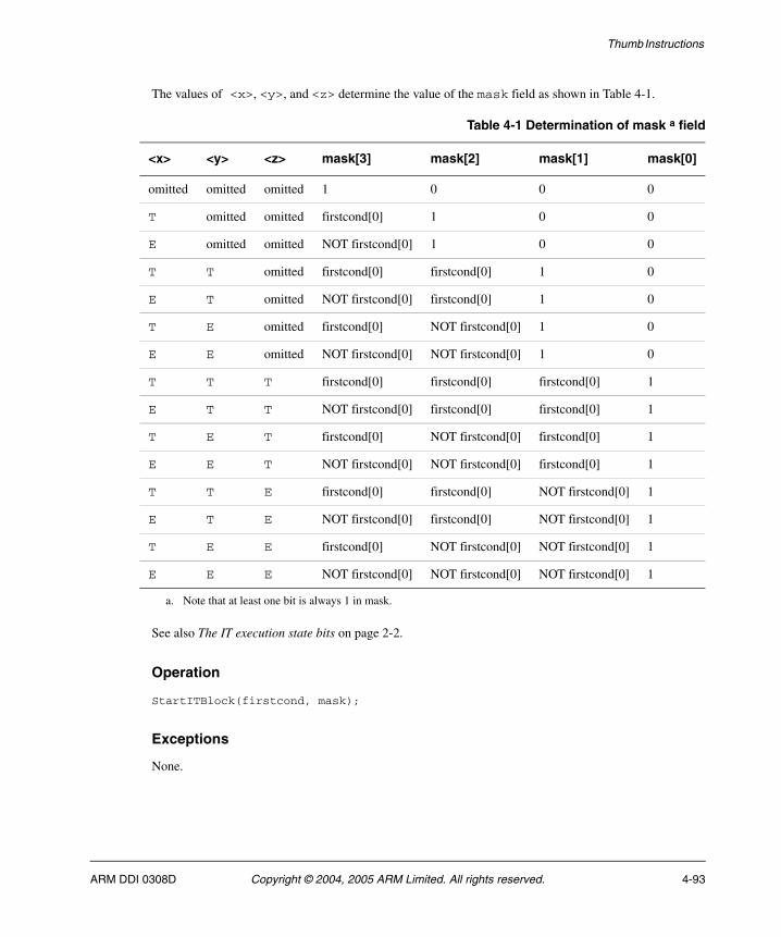
Thumb Instructions
The values of <x>, <y>, and <z> determine the value of the mask field as shown in Table 4-1.
See also The IT execution state bits on page 2-2.
Operation
StartITBlock(firstcond, mask);
Exceptions
None.
Table 4-1 Determination of mask a field
<x> <y> <z> mask[3] mask[2] mask[1] mask[0]
omitted omitted omitted 1 0 0 0
T omitted omitted firstcond[0] 1 0 0
E omitted omitted NOT firstcond[0] 1 0 0
T T omitted firstcond[0] firstcond[0] 1 0
E T omitted NOT firstcond[0] firstcond[0] 1 0
T E omitted firstcond[0] NOT firstcond[0] 1 0
E E omitted NOT firstcond[0] NOT firstcond[0] 1 0
T T T firstcond[0] firstcond[0] firstcond[0] 1
E T T NOT firstcond[0] firstcond[0] firstcond[0] 1
T E T firstcond[0] NOT firstcond[0] firstcond[0] 1
E E T NOT firstcond[0] NOT firstcond[0] firstcond[0] 1
T T E firstcond[0] firstcond[0] NOT firstcond[0] 1
E T E NOT firstcond[0] firstcond[0] NOT firstcond[0] 1
T E E firstcond[0] NOT firstcond[0] NOT firstcond[0] 1
E E E NOT firstcond[0] NOT firstcond[0] NOT firstcond[0] 1
a. Note that at least one bit is always 1 in mask.
ARM DDI 0308D Copyright © 2004, 2005 ARM Limited. All rights reserved. 4-93
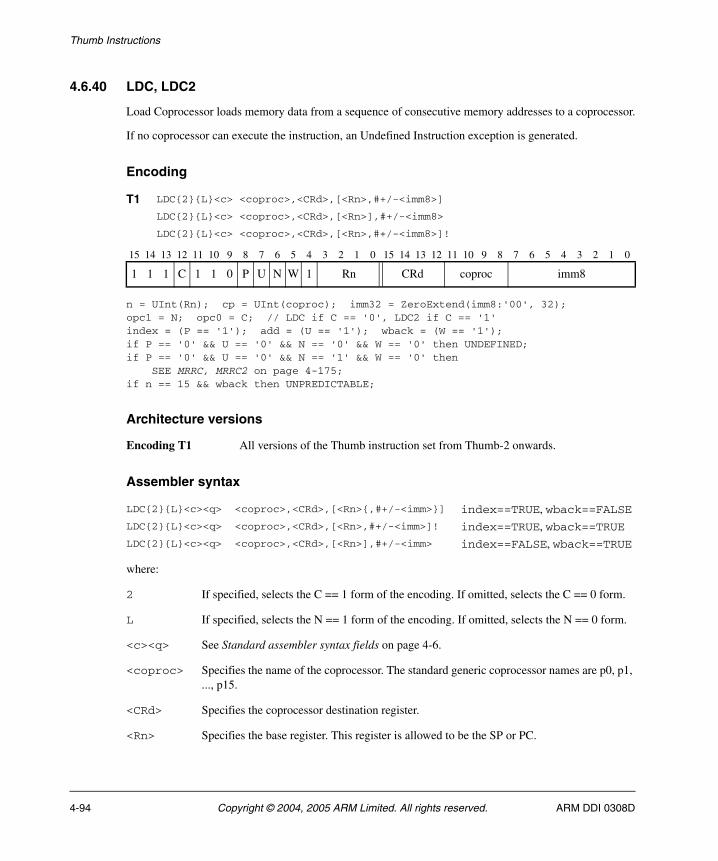
Thumb Instructions
4.6.40 LDC, LDC2
Load Coprocessor loads memory data from a sequence of consecutive memory addresses to a coprocessor.
If no coprocessor can execute the instruction, an Undefined Instruction exception is generated.
Encoding
n = UInt(Rn); cp = UInt(coproc); imm32 = ZeroExtend(imm8:'00', 32);opc1 = N; opc0 = C; // LDC if C == '0', LDC2 if C == '1'index = (P == '1'); add = (U == '1'); wback = (W == '1');if P == '0' && U == '0' && N == '0' && W == '0' then UNDEFINED;if P == '0' && U == '0' && N == '1' && W == '0' then SEE MRRC, MRRC2 on page 4-175;if n == 15 && wback then UNPREDICTABLE;
Architecture versions
Encoding T1 All versions of the Thumb instruction set from Thumb-2 onwards.
Assembler syntax
where:
2 If specified, selects the C == 1 form of the encoding. If omitted, selects the C == 0 form.
L If specified, selects the N == 1 form of the encoding. If omitted, selects the N == 0 form.
<c><q> See Standard assembler syntax fields on page 4-6.
<coproc> Specifies the name of the coprocessor. The standard generic coprocessor names are p0, p1, ..., p15.
<CRd> Specifies the coprocessor destination register.
<Rn> Specifies the base register. This register is allowed to be the SP or PC.
T1 LDC{2}{L}<c> <coproc>,<CRd>,[<Rn>,#+/-<imm8>]
LDC{2}{L}<c> <coproc>,<CRd>,[<Rn>],#+/-<imm8>
LDC{2}{L}<c> <coproc>,<CRd>,[<Rn>,#+/-<imm8>]!
15 14 13 12 11 10 9 8 7 6 5 4 3 2 1 0 15 14 13 12 11 10 9 8 7 6 5 4 3 2 1 0
1 1 1 C 1 1 0 P U N W 1 Rn CRd coproc imm8
LDC{2}{L}<c><q> <coproc>,<CRd>,[<Rn>{,#+/-<imm>}] index==TRUE, wback==FALSELDC{2}{L}<c><q> <coproc>,<CRd>,[<Rn>,#+/-<imm>]! index==TRUE, wback==TRUELDC{2}{L}<c><q> <coproc>,<CRd>,[<Rn>],#+/-<imm> index==FALSE, wback==TRUE
4-94 Copyright © 2004, 2005 ARM Limited. All rights reserved. ARM DDI 0308D
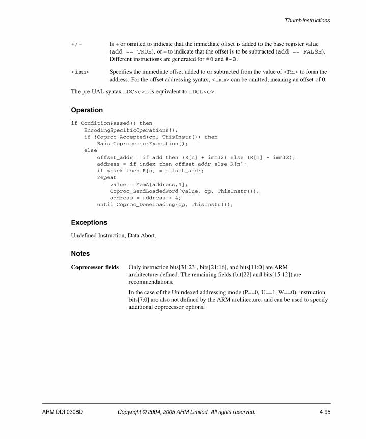
Thumb Instructions
+/- Is + or omitted to indicate that the immediate offset is added to the base register value (add == TRUE), or – to indicate that the offset is to be subtracted (add == FALSE). Different instructions are generated for #0 and #-0.
<imm> Specifies the immediate offset added to or subtracted from the value of <Rn> to form the address. For the offset addressing syntax, <imm> can be omitted, meaning an offset of 0.
The pre-UAL syntax LDC<c>L is equivalent to LDCL<c>.
Operation
if ConditionPassed() then EncodingSpecificOperations(); if !Coproc_Accepted(cp, ThisInstr()) then RaiseCoprocessorException(); else offset_addr = if add then (R[n] + imm32) else (R[n] - imm32); address = if index then offset_addr else R[n]; if wback then R[n] = offset_addr; repeat value = MemA[address,4]; Coproc_SendLoadedWord(value, cp, ThisInstr()); address = address + 4; until Coproc_DoneLoading(cp, ThisInstr());
Exceptions
Undefined Instruction, Data Abort.
Notes
Coprocessor fields Only instruction bits[31:23], bits[21:16], and bits[11:0] are ARM architecture-defined. The remaining fields (bit[22] and bits[15:12]) are recommendations,
In the case of the Unindexed addressing mode (P==0, U==1, W==0), instruction bits[7:0] are also not defined by the ARM architecture, and can be used to specify additional coprocessor options.
ARM DDI 0308D Copyright © 2004, 2005 ARM Limited. All rights reserved. 4-95
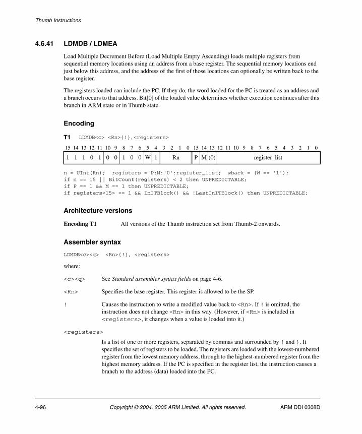
Thumb Instructions
4.6.41 LDMDB / LDMEA
Load Multiple Decrement Before (Load Multiple Empty Ascending) loads multiple registers from sequential memory locations using an address from a base register. The sequential memory locations end just below this address, and the address of the first of those locations can optionally be written back to the base register.
The registers loaded can include the PC. If they do, the word loaded for the PC is treated as an address and a branch occurs to that address. Bit[0] of the loaded value determines whether execution continues after this branch in ARM state or in Thumb state.
Encoding
n = UInt(Rn); registers = P:M:'0':register_list; wback = (W == '1');if n == 15 || BitCount(registers) < 2 then UNPREDICTABLE;if P == 1 && M == 1 then UNPREDICTABLE;if registers<15> == 1 && InITBlock() && !LastInITBlock() then UNPREDICTABLE;
Architecture versions
Encoding T1 All versions of the Thumb instruction set from Thumb-2 onwards.
Assembler syntax
LDMDB<c><q> <Rn>{!}, <registers>
where:
<c><q> See Standard assembler syntax fields on page 4-6.
<Rn> Specifies the base register. This register is allowed to be the SP.
! Causes the instruction to write a modified value back to <Rn>. If ! is omitted, the instruction does not change <Rn> in this way. (However, if <Rn> is included in <registers>, it changes when a value is loaded into it.)
<registers>
Is a list of one or more registers, separated by commas and surrounded by { and }. It specifies the set of registers to be loaded. The registers are loaded with the lowest-numbered register from the lowest memory address, through to the highest-numbered register from the highest memory address. If the PC is specified in the register list, the instruction causes a branch to the address (data) loaded into the PC.
T1 LDMDB<c> <Rn>{!},<registers>
15 14 13 12 11 10 9 8 7 6 5 4 3 2 1 0 15 14 13 12 11 10 9 8 7 6 5 4 3 2 1 0
1 1 1 0 1 0 0 1 0 0 W 1 Rn P M (0) register_list
4-96 Copyright © 2004, 2005 ARM Limited. All rights reserved. ARM DDI 0308D
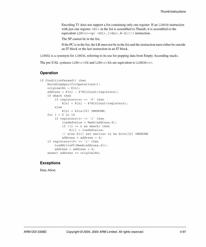
Thumb Instructions
Encoding T1 does not support a list containing only one register. If an LDMDB instruction with just one register <Rt> in the list is assembled to Thumb, it is assembled to the equivalent LDR<c><q> <Rt>,[<Rn>,#-4]{!} instruction.
The SP cannot be in the list.
If the PC is in the list, the LR must not be in the list and the instruction must either be outside an IT block or the last instruction in an IT block.
LDMEA is a synonym for LDMDB, referring to its use for popping data from Empty Ascending stacks.
The pre-UAL syntaxes LDM<c>DB and LDM<c>EA are equivalent to LDMDB<c>.
Operation
if ConditionPassed() then EncodingSpecificOperations(); originalRn = R[n]; address = R[n] - 4*BitCount(registers); if wback then if registers<n> == '0' then R[n] = R[n] - 4*BitCount(registers); else R[n] = bits(32) UNKNOWN; for i = 0 to 14 if registers<i> == '1' then loadedvalue = MemA[address,4]; if !(i == n && wback) then R[i] = loadedvalue; // else R[i] set earlier to be bits[32] UNKNOWN address = address + 4; if registers<15> == '1' then LoadWritePC(MemA[address,4]); address = address + 4; assert address == originalRn;
Exceptions
Data Abort.
ARM DDI 0308D Copyright © 2004, 2005 ARM Limited. All rights reserved. 4-97
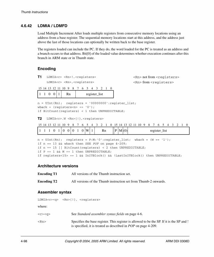
Thumb Instructions
4.6.42 LDMIA / LDMFD
Load Multiple Increment After loads multiple registers from consecutive memory locations using an address from a base register. The sequential memory locations start at this address, and the address just above the last of those locations can optionally be written back to the base register.
The registers loaded can include the PC. If they do, the word loaded for the PC is treated as an address and a branch occurs to that address. Bit[0] of the loaded value determines whether execution continues after this branch in ARM state or in Thumb state.
Encoding
n = UInt(Rn); registers = '00000000':register_list;wback = (registers<n> == '0');if BitCount(registers) < 1 then UNPREDICTABLE;
n = UInt(Rn); registers = P:M:'0':register_list; wback = (W == '1');if n == 13 && wback then SEE POP on page 4-209;if n == 15 || BitCount(registers) < 2 then UNPREDICTABLE;if P == 1 && M == 1 then UNPREDICTABLE;if registers<15> == 1 && InITBlock() && !LastInITBlock() then UNPREDICTABLE;
Architecture versions
Encoding T1 All versions of the Thumb instruction set.
Encoding T2 All versions of the Thumb instruction set from Thumb-2 onwards.
Assembler syntax
LDMIA<c><q> <Rn>{!}, <registers>
where:
<c><q> See Standard assembler syntax fields on page 4-6.
<Rn> Specifies the base register. This register is allowed to be the SP. If it is the SP and ! is specified, it is treated as described in POP on page 4-209.
T1 LDMIA<c> <Rn>!,<registers> <Rn> not from <registers>LDMIA<c> <Rn>,<registers> <Rn> from <registers>
15 14 13 12 11 10 9 8 7 6 5 4 3 2 1 0
1 1 0 0 1 Rn register_list
T2 LDMIA<c>.W <Rn>{!},<registers>
15 14 13 12 11 10 9 8 7 6 5 4 3 2 1 0 15 14 13 12 11 10 9 8 7 6 5 4 3 2 1 0
1 1 1 0 1 0 0 0 1 0 W 1 Rn P M (0) register_list
4-98 Copyright © 2004, 2005 ARM Limited. All rights reserved. ARM DDI 0308D
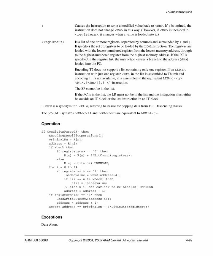
Thumb Instructions
! Causes the instruction to write a modified value back to <Rn>. If ! is omitted, the instruction does not change <Rn> in this way. (However, if <Rn> is included in <registers>, it changes when a value is loaded into it.)
<registers> Is a list of one or more registers, separated by commas and surrounded by { and }. It specifies the set of registers to be loaded by the LDM instruction. The registers are loaded with the lowest-numbered register from the lowest memory address, through to the highest-numbered register from the highest memory address. If the PC is specified in the register list, the instruction causes a branch to the address (data) loaded into the PC.
Encoding T2 does not support a list containing only one register. If an LDMIA instruction with just one register <Rt> in the list is assembled to Thumb and encoding T1 is not available, it is assembled to the equivalent LDR<c><q> <Rt>,[<Rn>]{,#-4} instruction.
The SP cannot be in the list.
If the PC is in the list, the LR must not be in the list and the instruction must either be outside an IT block or the last instruction in an IT block.
LDMFD is a synonym for LDMIA, referring to its use for popping data from Full Descending stacks.
The pre-UAL syntaxes LDM<c>IA and LDM<c>FD are equivalent to LDMIA<c>.
Operation
if ConditionPassed() then EncodingSpecificOperations(); originalRn = R[n]; address = R[n]; if wback then if registers<n> == '0' then R[n] = R[n] + 4*BitCount(registers); else R[n] = bits(32) UNKNOWN; for i = 0 to 14 if registers<i> == '1' then loadedvalue = MemA[address,4]; if !(i == n && wback) then R[i] = loadedvalue; // else R[i] set earlier to be bits[32] UNKNOWN address = address + 4; if registers<15> == '1' then LoadWritePC(MemA[address,4]); address = address + 4; assert address == originalRn + 4*BitCount(registers);
Exceptions
Data Abort.
ARM DDI 0308D Copyright © 2004, 2005 ARM Limited. All rights reserved. 4-99
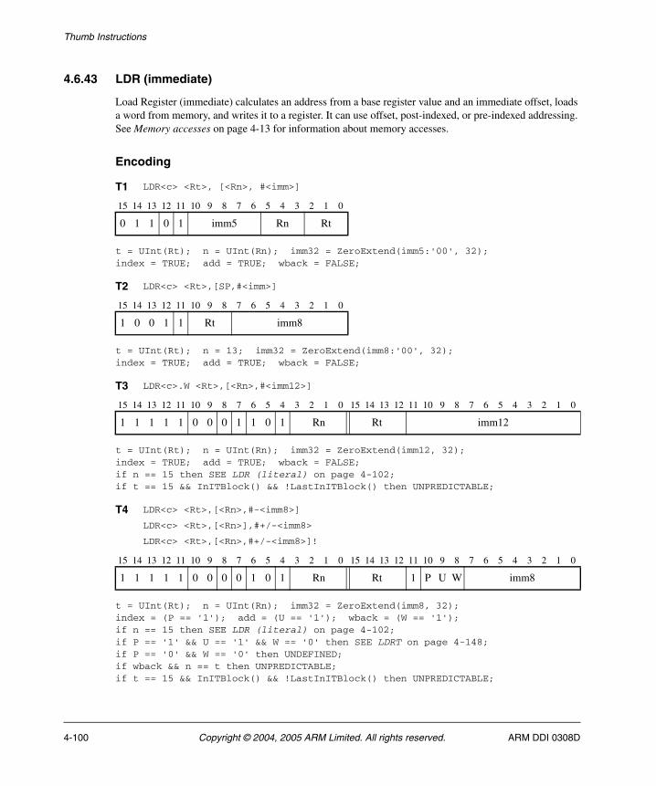
Thumb Instructions
4.6.43 LDR (immediate)
Load Register (immediate) calculates an address from a base register value and an immediate offset, loads a word from memory, and writes it to a register. It can use offset, post-indexed, or pre-indexed addressing. See Memory accesses on page 4-13 for information about memory accesses.
Encoding
t = UInt(Rt); n = UInt(Rn); imm32 = ZeroExtend(imm5:'00', 32);index = TRUE; add = TRUE; wback = FALSE;
t = UInt(Rt); n = 13; imm32 = ZeroExtend(imm8:'00', 32);index = TRUE; add = TRUE; wback = FALSE;
t = UInt(Rt); n = UInt(Rn); imm32 = ZeroExtend(imm12, 32);index = TRUE; add = TRUE; wback = FALSE;if n == 15 then SEE LDR (literal) on page 4-102;if t == 15 && InITBlock() && !LastInITBlock() then UNPREDICTABLE;
t = UInt(Rt); n = UInt(Rn); imm32 = ZeroExtend(imm8, 32);index = (P == '1'); add = (U == '1'); wback = (W == '1');if n == 15 then SEE LDR (literal) on page 4-102;if P == '1' && U == '1' && W == '0' then SEE LDRT on page 4-148;if P == '0' && W == '0' then UNDEFINED;if wback && n == t then UNPREDICTABLE;if t == 15 && InITBlock() && !LastInITBlock() then UNPREDICTABLE;
T1 LDR<c> <Rt>, [<Rn>, #<imm>]
15 14 13 12 11 10 9 8 7 6 5 4 3 2 1 0
0 1 1 0 1 imm5 Rn Rt
T2 LDR<c> <Rt>,[SP,#<imm>]
15 14 13 12 11 10 9 8 7 6 5 4 3 2 1 0
1 0 0 1 1 Rt imm8
T3 LDR<c>.W <Rt>,[<Rn>,#<imm12>]
15 14 13 12 11 10 9 8 7 6 5 4 3 2 1 0 15 14 13 12 11 10 9 8 7 6 5 4 3 2 1 0
1 1 1 1 1 0 0 0 1 1 0 1 Rn Rt imm12
T4 LDR<c> <Rt>,[<Rn>,#-<imm8>]
LDR<c> <Rt>,[<Rn>],#+/-<imm8>
LDR<c> <Rt>,[<Rn>,#+/-<imm8>]!
15 14 13 12 11 10 9 8 7 6 5 4 3 2 1 0 15 14 13 12 11 10 9 8 7 6 5 4 3 2 1 0
1 1 1 1 1 0 0 0 0 1 0 1 Rn Rt 1 P U W imm8
4-100 Copyright © 2004, 2005 ARM Limited. All rights reserved. ARM DDI 0308D
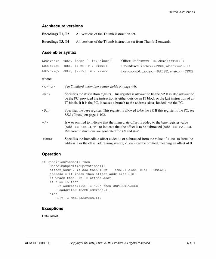
Thumb Instructions
Architecture versions
Encodings T1, T2 All versions of the Thumb instruction set.
Encodings T3, T4 All versions of the Thumb instruction set from Thumb-2 onwards.
Assembler syntax
where:
<c><q> See Standard assembler syntax fields on page 4-6.
<Rt> Specifies the destination register. This register is allowed to be the SP. It is also allowed to be the PC, provided the instruction is either outside an IT block or the last instruction of an IT block. If it is the PC, it causes a branch to the address (data) loaded into the PC.
<Rn> Specifies the base register. This register is allowed to be the SP. If this register is the PC, see LDR (literal) on page 4-102.
+/- Is + or omitted to indicate that the immediate offset is added to the base register value (add == TRUE), or – to indicate that the offset is to be subtracted (add == FALSE). Different instructions are generated for #0 and #-0.
<imm> Specifies the immediate offset added to or subtracted from the value of <Rn> to form the address. For the offset addressing syntax, <imm> can be omitted, meaning an offset of 0.
Operation
if ConditionPassed() then EncodingSpecificOperations(); offset_addr = if add then (R[n] + imm32) else (R[n] - imm32); address = if index then offset_addr else R[n]; if wback then R[n] = offset_addr; if t == 15 then if address<1:0> != '00' then UNPREDICTABLE; LoadWritePC(MemU[address,4]); else R[t] = MemU[address,4];
Exceptions
Data Abort.
LDR<c><q> <Rt>, [<Rn> {, #+/-<imm>}] Offset: index==TRUE, wback==FALSELDR<c><q> <Rt>, [<Rn>, #+/-<imm>]! Pre-indexed: index==TRUE, wback==TRUELDR<c><q> <Rt>, [<Rn>], #+/-<imm> Post-indexed: index==FALSE, wback==TRUE
ARM DDI 0308D Copyright © 2004, 2005 ARM Limited. All rights reserved. 4-101
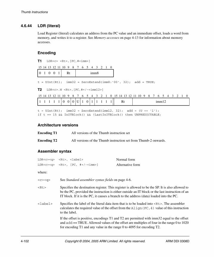
Thumb Instructions
4.6.44 LDR (literal)
Load Register (literal) calculates an address from the PC value and an immediate offset, loads a word from memory, and writes it to a register. See Memory accesses on page 4-13 for information about memory accesses.
Encoding
t = UInt(Rt); imm32 = ZeroExtend(imm8:'00', 32); add = TRUE;
t = UInt(Rt); imm32 = ZeroExtend(imm12, 32); add = (U == '1');if t == 15 && InITBlock() && !LastInITBlock() then UNPREDICTABLE;
Architecture versions
Encoding T1 All versions of the Thumb instruction set
Encoding T2 All versions of the Thumb instruction set from Thumb-2 onwards.
Assembler syntax
where:
<c><q> See Standard assembler syntax fields on page 4-6.
<Rt> Specifies the destination register. This register is allowed to be the SP. It is also allowed to be the PC, provided the instruction is either outside an IT block or the last instruction of an IT block. If it is the PC, it causes a branch to the address (data) loaded into the PC.
<label> Specifies the label of the literal data item that is to be loaded into <Rt>. The assembler calculates the required value of the offset from the Align(PC,4) value of this instruction to the label.
If the offset is positive, encodings T1 and T2 are permitted with imm32 equal to the offset and add == TRUE. Allowed values of the offset are multiples of four in the range 0 to 1020 for encoding T1 and any value in the range 0 to 4095 for encoding T2.
T1 LDR<c> <Rt>,[PC,#<imm>]
15 14 13 12 11 10 9 8 7 6 5 4 3 2 1 0
0 1 0 0 1 Rt imm8
T2 LDR<c>.W <Rt>,[PC,#+/-<imm12>]
15 14 13 12 11 10 9 8 7 6 5 4 3 2 1 0 15 14 13 12 11 10 9 8 7 6 5 4 3 2 1 0
1 1 1 1 1 0 0 0 U 1 0 1 1 1 1 1 Rt imm12
LDR<c><q> <Rt>, <label> Normal formLDR<c><q> <Rt>, [PC, #+/-<imm>] Alternative form
4-102 Copyright © 2004, 2005 ARM Limited. All rights reserved. ARM DDI 0308D
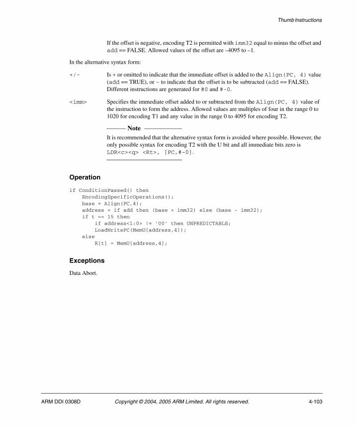
Thumb Instructions
If the offset is negative, encoding T2 is permitted with imm32 equal to minus the offset and add == FALSE. Allowed values of the offset are –4095 to –1.
In the alternative syntax form:
+/- Is + or omitted to indicate that the immediate offset is added to the Align(PC, 4) value (add == TRUE), or - to indicate that the offset is to be subtracted (add == FALSE). Different instructions are generated for #0 and #-0.
<imm> Specifies the immediate offset added to or subtracted from the Align(PC, 4) value of the instruction to form the address. Allowed values are multiples of four in the range 0 to 1020 for encoding T1 and any value in the range 0 to 4095 for encoding T2.
Note It is recommended that the alternative syntax form is avoided where possible. However, the
only possible syntax for encoding T2 with the U bit and all immediate bits zero is LDR<c><q> <Rt>, [PC,#-0].
Operation
if ConditionPassed() then EncodingSpecificOperations(); base = Align(PC,4); address = if add then (base + imm32) else (base - imm32); if t == 15 then if address<1:0> != '00' then UNPREDICTABLE; LoadWritePC(MemU[address,4]); else R[t] = MemU[address,4];
Exceptions
Data Abort.
ARM DDI 0308D Copyright © 2004, 2005 ARM Limited. All rights reserved. 4-103
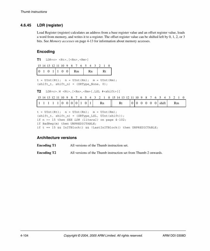
Thumb Instructions
4.6.45 LDR (register)
Load Register (register) calculates an address from a base register value and an offset register value, loads a word from memory, and writes it to a register. The offset register value can be shifted left by 0, 1, 2, or 3 bits. See Memory accesses on page 4-13 for information about memory accesses.
Encoding
t = UInt(Rt); n = UInt(Rn); m = UInt(Rm);(shift_t, shift_n) = (SRType_None, 0);
t = UInt(Rt); n = UInt(Rn); m = UInt(Rm);(shift_t, shift_n) = (SRType_LSL, UInt(shift));if n == 15 then SEE LDR (literal) on page 4-102;if BadReg(m) then UNPREDICTABLE;if t == 15 && InITBlock() && !LastInITBlock() then UNPREDICTABLE;
Architecture versions
Encoding T1 All versions of the Thumb instruction set.
Encoding T2 All versions of the Thumb instruction set from Thumb-2 onwards.
T1 LDR<c> <Rt>,[<Rn>,<Rm>]
15 14 13 12 11 10 9 8 7 6 5 4 3 2 1 0
0 1 0 1 1 0 0 Rm Rn Rt
T2 LDR<c>.W <Rt>,[<Rn>,<Rm>{,LSL #<shift>}]
15 14 13 12 11 10 9 8 7 6 5 4 3 2 1 0 15 14 13 12 11 10 9 8 7 6 5 4 3 2 1 0
1 1 1 1 1 0 0 0 0 1 0 1 Rn Rt 0 0 0 0 0 0 shift Rm
4-104 Copyright © 2004, 2005 ARM Limited. All rights reserved. ARM DDI 0308D
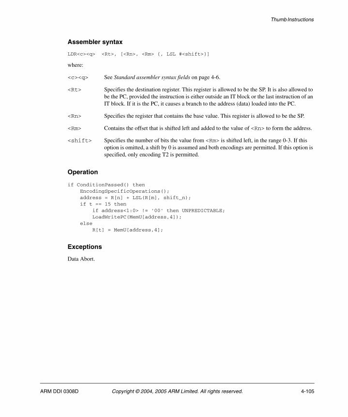
Thumb Instructions
Assembler syntax
LDR<c><q> <Rt>, [<Rn>, <Rm> {, LSL #<shift>}]
where:
<c><q> See Standard assembler syntax fields on page 4-6.
<Rt> Specifies the destination register. This register is allowed to be the SP. It is also allowed to be the PC, provided the instruction is either outside an IT block or the last instruction of an IT block. If it is the PC, it causes a branch to the address (data) loaded into the PC.
<Rn> Specifies the register that contains the base value. This register is allowed to be the SP.
<Rm> Contains the offset that is shifted left and added to the value of <Rn> to form the address.
<shift> Specifies the number of bits the value from <Rm> is shifted left, in the range 0-3. If this option is omitted, a shift by 0 is assumed and both encodings are permitted. If this option is specified, only encoding T2 is permitted.
Operation
if ConditionPassed() then EncodingSpecificOperations(); address = R[n] + LSL(R[m], shift_n); if t == 15 then if address<1:0> != '00' then UNPREDICTABLE; LoadWritePC(MemU[address,4]); else R[t] = MemU[address,4];
Exceptions
Data Abort.
ARM DDI 0308D Copyright © 2004, 2005 ARM Limited. All rights reserved. 4-105
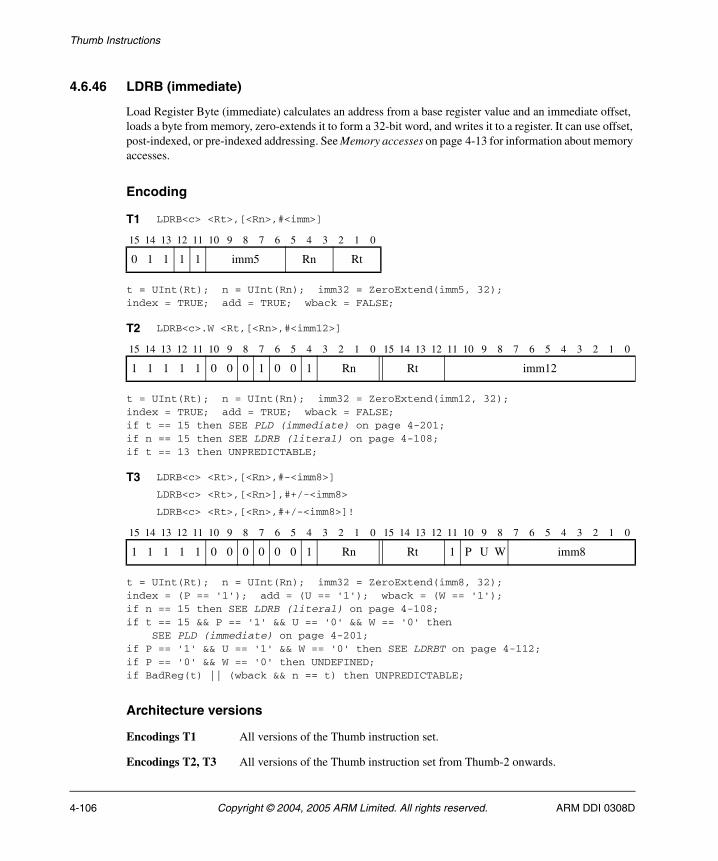
Thumb Instructions
4.6.46 LDRB (immediate)
Load Register Byte (immediate) calculates an address from a base register value and an immediate offset, loads a byte from memory, zero-extends it to form a 32-bit word, and writes it to a register. It can use offset, post-indexed, or pre-indexed addressing. See Memory accesses on page 4-13 for information about memory accesses.
Encoding
t = UInt(Rt); n = UInt(Rn); imm32 = ZeroExtend(imm5, 32);index = TRUE; add = TRUE; wback = FALSE;
t = UInt(Rt); n = UInt(Rn); imm32 = ZeroExtend(imm12, 32);index = TRUE; add = TRUE; wback = FALSE;if t == 15 then SEE PLD (immediate) on page 4-201;if n == 15 then SEE LDRB (literal) on page 4-108;if t == 13 then UNPREDICTABLE;
t = UInt(Rt); n = UInt(Rn); imm32 = ZeroExtend(imm8, 32); index = (P == '1'); add = (U == '1'); wback = (W == '1'); if n == 15 then SEE LDRB (literal) on page 4-108;if t == 15 && P == '1' && U == '0' && W == '0' then SEE PLD (immediate) on page 4-201;if P == '1' && U == '1' && W == '0' then SEE LDRBT on page 4-112; if P == '0' && W == '0' then UNDEFINED; if BadReg(t) || (wback && n == t) then UNPREDICTABLE;
Architecture versions
Encodings T1 All versions of the Thumb instruction set.
Encodings T2, T3 All versions of the Thumb instruction set from Thumb-2 onwards.
T1 LDRB<c> <Rt>,[<Rn>,#<imm>]
15 14 13 12 11 10 9 8 7 6 5 4 3 2 1 0
0 1 1 1 1 imm5 Rn Rt
T2 LDRB<c>.W <Rt,[<Rn>,#<imm12>]
15 14 13 12 11 10 9 8 7 6 5 4 3 2 1 0 15 14 13 12 11 10 9 8 7 6 5 4 3 2 1 0
1 1 1 1 1 0 0 0 1 0 0 1 Rn Rt imm12
T3 LDRB<c> <Rt>,[<Rn>,#-<imm8>]
LDRB<c> <Rt>,[<Rn>],#+/-<imm8>
LDRB<c> <Rt>,[<Rn>,#+/-<imm8>]!
15 14 13 12 11 10 9 8 7 6 5 4 3 2 1 0 15 14 13 12 11 10 9 8 7 6 5 4 3 2 1 0
1 1 1 1 1 0 0 0 0 0 0 1 Rn Rt 1 P U W imm8
4-106 Copyright © 2004, 2005 ARM Limited. All rights reserved. ARM DDI 0308D

Thumb Instructions
Assembler syntax
where:
<c><q> See Standard assembler syntax fields on page 4-6.
<Rt> Specifies the destination register.
<Rn> Specifies the base register. This register is allowed to be the SP. If this register is the PC, see LDRB (literal) on page 4-108.
+/- Is + or omitted to indicate that the immediate offset is added to the base register value (add == TRUE), or – to indicate that the offset is to be subtracted (add == FALSE). Different instructions are generated for #0 and #-0.
<imm> Specifies the immediate offset added to or subtracted from the value of <Rn> to form the address. For the offset addressing syntax, <imm> can be omitted, meaning an offset of 0.
The pre-UAL syntax LDR<c>B is equivalent to LDRB<c>.
Operation
if ConditionPassed() then EncodingSpecificOperations(); offset_addr = if add then (R[n] + imm32) else (R[n] - imm32); address = if index then offset_addr else R[n]; if wback then R[n] = offset_addr; R[t] = ZeroExtend(MemU[address,1], 32);
Exceptions
Data Abort.
LDRB<c><q> <Rt>, [<Rn> {, #+/-<imm>}] Offset: index==TRUE, wback==FALSELDRB<c><q> <Rt>, [<Rn>, #+/-<imm>]! Pre-indexed: index==TRUE, wback==TRUELDRB<c><q> <Rt>, [<Rn>], #+/-<imm> Post-indexed: index==FALSE, wback==TRUE
ARM DDI 0308D Copyright © 2004, 2005 ARM Limited. All rights reserved. 4-107
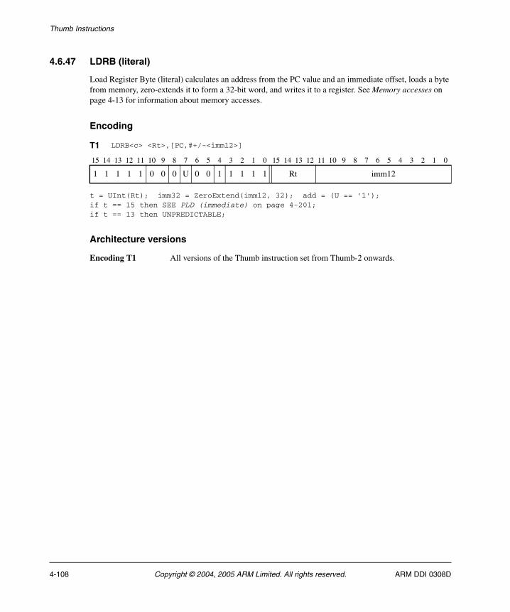
Thumb Instructions
4.6.47 LDRB (literal)
Load Register Byte (literal) calculates an address from the PC value and an immediate offset, loads a byte from memory, zero-extends it to form a 32-bit word, and writes it to a register. See Memory accesses on page 4-13 for information about memory accesses.
Encoding
t = UInt(Rt); imm32 = ZeroExtend(imm12, 32); add = (U == '1'); if t == 15 then SEE PLD (immediate) on page 4-201; if t == 13 then UNPREDICTABLE;
Architecture versions
Encoding T1 All versions of the Thumb instruction set from Thumb-2 onwards.
T1 LDRB<c> <Rt>,[PC,#+/-<imm12>]
15 14 13 12 11 10 9 8 7 6 5 4 3 2 1 0 15 14 13 12 11 10 9 8 7 6 5 4 3 2 1 0
1 1 1 1 1 0 0 0 U 0 0 1 1 1 1 1 Rt imm12
4-108 Copyright © 2004, 2005 ARM Limited. All rights reserved. ARM DDI 0308D
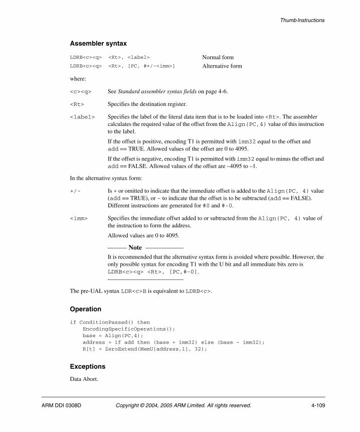
Thumb Instructions
Assembler syntax
where:
<c><q> See Standard assembler syntax fields on page 4-6.
<Rt> Specifies the destination register.
<label> Specifies the label of the literal data item that is to be loaded into <Rt>. The assembler calculates the required value of the offset from the Align(PC,4) value of this instruction to the label.
If the offset is positive, encoding T1 is permitted with imm32 equal to the offset and add == TRUE. Allowed values of the offset are 0 to 4095.
If the offset is negative, encoding T1 is permitted with imm32 equal to minus the offset and add == FALSE. Allowed values of the offset are –4095 to –1.
In the alternative syntax form:
+/- Is + or omitted to indicate that the immediate offset is added to the Align(PC, 4) value (add == TRUE), or - to indicate that the offset is to be subtracted (add == FALSE). Different instructions are generated for #0 and #-0.
<imm> Specifies the immediate offset added to or subtracted from the Align(PC, 4) value of the instruction to form the address.
Allowed values are 0 to 4095.
Note It is recommended that the alternative syntax form is avoided where possible. However, the
only possible syntax for encoding T1 with the U bit and all immediate bits zero is LDRB<c><q> <Rt>, [PC,#-0].
The pre-UAL syntax LDR<c>B is equivalent to LDRB<c>.
Operation
if ConditionPassed() then EncodingSpecificOperations(); base = Align(PC,4); address = if add then (base + imm32) else (base - imm32); R[t] = ZeroExtend(MemU[address,1], 32);
Exceptions
Data Abort.
LDRB<c><q> <Rt>, <label> Normal formLDRB<c><q> <Rt>, [PC, #+/-<imm>] Alternative form
ARM DDI 0308D Copyright © 2004, 2005 ARM Limited. All rights reserved. 4-109
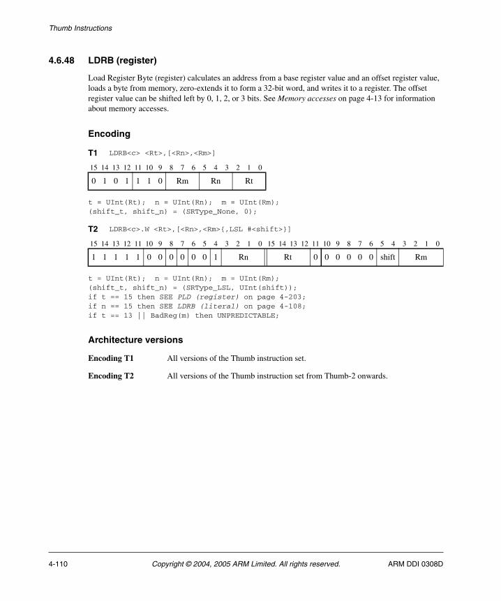
Thumb Instructions
4.6.48 LDRB (register)
Load Register Byte (register) calculates an address from a base register value and an offset register value, loads a byte from memory, zero-extends it to form a 32-bit word, and writes it to a register. The offset register value can be shifted left by 0, 1, 2, or 3 bits. See Memory accesses on page 4-13 for information about memory accesses.
Encoding
t = UInt(Rt); n = UInt(Rn); m = UInt(Rm);(shift_t, shift_n) = (SRType_None, 0);
t = UInt(Rt); n = UInt(Rn); m = UInt(Rm); (shift_t, shift_n) = (SRType_LSL, UInt(shift)); if t == 15 then SEE PLD (register) on page 4-203; if n == 15 then SEE LDRB (literal) on page 4-108; if t == 13 || BadReg(m) then UNPREDICTABLE;
Architecture versions
Encoding T1 All versions of the Thumb instruction set.
Encoding T2 All versions of the Thumb instruction set from Thumb-2 onwards.
T1 LDRB<c> <Rt>,[<Rn>,<Rm>]
15 14 13 12 11 10 9 8 7 6 5 4 3 2 1 0
0 1 0 1 1 1 0 Rm Rn Rt
T2 LDRB<c>.W <Rt>,[<Rn>,<Rm>{,LSL #<shift>}]
15 14 13 12 11 10 9 8 7 6 5 4 3 2 1 0 15 14 13 12 11 10 9 8 7 6 5 4 3 2 1 0
1 1 1 1 1 0 0 0 0 0 0 1 Rn Rt 0 0 0 0 0 0 shift Rm
4-110 Copyright © 2004, 2005 ARM Limited. All rights reserved. ARM DDI 0308D
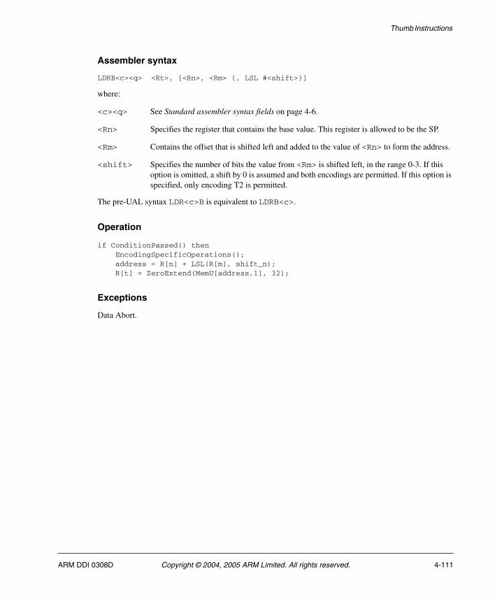
Thumb Instructions
Assembler syntax
LDRB<c><q> <Rt>, [<Rn>, <Rm> {, LSL #<shift>}]
where:
<c><q> See Standard assembler syntax fields on page 4-6.
<Rn> Specifies the register that contains the base value. This register is allowed to be the SP.
<Rm> Contains the offset that is shifted left and added to the value of <Rn> to form the address.
<shift> Specifies the number of bits the value from <Rm> is shifted left, in the range 0-3. If this option is omitted, a shift by 0 is assumed and both encodings are permitted. If this option is specified, only encoding T2 is permitted.
The pre-UAL syntax LDR<c>B is equivalent to LDRB<c>.
Operation
if ConditionPassed() then EncodingSpecificOperations(); address = R[n] + LSL(R[m], shift_n); R[t] = ZeroExtend(MemU[address,1], 32);
Exceptions
Data Abort.
ARM DDI 0308D Copyright © 2004, 2005 ARM Limited. All rights reserved. 4-111
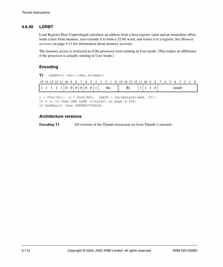
Thumb Instructions
4.6.49 LDRBT
Load Register Byte Unprivileged calculates an address from a base register value and an immediate offset, loads a byte from memory, zero-extends it to form a 32-bit word, and writes it to a register. See Memory accesses on page 4-13 for information about memory accesses.
The memory access is restricted as if the processor were running in User mode. (This makes no difference if the processor is actually running in User mode.)
Encoding
t = UInt(Rt); n = UInt(Rn); imm32 = ZeroExtend(imm8, 32);if n == 15 then SEE LDRB (literal) on page 4-108;if BadReg(t) then UNPREDICTABLE;
Architecture versions
Encoding T1 All versions of the Thumb instruction set from Thumb-2 onwards.
T1 LDRBT<c> <Rt>,[<Rn>,#<imm8>]
15 14 13 12 11 10 9 8 7 6 5 4 3 2 1 0 15 14 13 12 11 10 9 8 7 6 5 4 3 2 1 0
1 1 1 1 1 0 0 0 0 0 0 1 Rn Rt 1 1 1 0 imm8
4-112 Copyright © 2004, 2005 ARM Limited. All rights reserved. ARM DDI 0308D
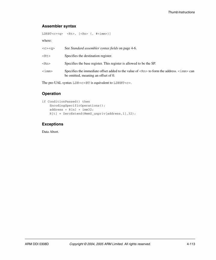
Thumb Instructions
Assembler syntax
LDRBT<c><q> <Rt>, [<Rn> {, #<imm>}]
where:
<c><q> See Standard assembler syntax fields on page 4-6.
<Rt> Specifies the destination register.
<Rn> Specifies the base register. This register is allowed to be the SP.
<imm> Specifies the immediate offset added to the value of <Rn> to form the address. <imm> can be omitted, meaning an offset of 0.
The pre-UAL syntax LDR<c>BT is equivalent to LDRBT<c>.
Operation
if ConditionPassed() then EncodingSpecificOperations(); address = R[n] + imm32; R[t] = ZeroExtend(MemU_unpriv[address,1],32);
Exceptions
Data Abort.
ARM DDI 0308D Copyright © 2004, 2005 ARM Limited. All rights reserved. 4-113

Thumb Instructions
4.6.50 LDRD (immediate)
Load Register Double (immediate) calculates an address from a base register value and an immediate offset, loads two words from memory, and writes them to two registers. It can use offset, post-indexed, or pre-indexed addressing. See Memory accesses on page 4-13 for information about memory accesses.
Encoding
t = UInt(Rt); t2 = UInt(Rt2); n = UInt(Rn); imm32 = ZeroExtend(imm8:'00');index = (P == '1'); add = (U == '1'); wback = (W == '1');if P == '0' && W == '0' then SEE Load/store double and exclusive, and table branch on page 3-28;if wback && n == 15 then UNPREDICTABLE;if BadReg(t) || BadReg(t2) || t1 == t2 then UNPREDICTABLE;
Architecture versions
Encoding T1 All versions of the Thumb instruction set from Thumb-2 onwards.
T1 LDRD<c> <Rt>,<Rt2>,[<Rn>,#+/-<imm>]{!}
LDRD<c> <Rt>,<Rt2>,[<Rn>],#+/-<imm>
15 14 13 12 11 10 9 8 7 6 5 4 3 2 1 0 15 14 13 12 11 10 9 8 7 6 5 4 3 2 1 0
1 1 1 0 1 0 0 P U 1 W 1 Rn Rt Rt2 imm8
4-114 Copyright © 2004, 2005 ARM Limited. All rights reserved. ARM DDI 0308D
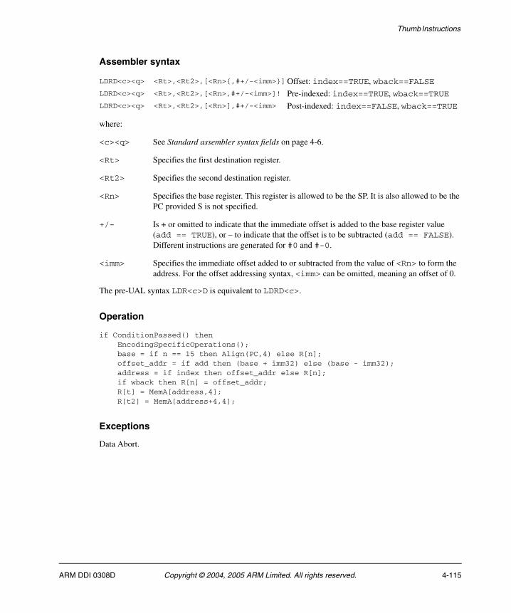
Thumb Instructions
Assembler syntax
where:
<c><q> See Standard assembler syntax fields on page 4-6.
<Rt> Specifies the first destination register.
<Rt2> Specifies the second destination register.
<Rn> Specifies the base register. This register is allowed to be the SP. It is also allowed to be the PC provided S is not specified.
+/- Is + or omitted to indicate that the immediate offset is added to the base register value (add == TRUE), or – to indicate that the offset is to be subtracted (add == FALSE). Different instructions are generated for #0 and #-0.
<imm> Specifies the immediate offset added to or subtracted from the value of <Rn> to form the address. For the offset addressing syntax, <imm> can be omitted, meaning an offset of 0.
The pre-UAL syntax LDR<c>D is equivalent to LDRD<c>.
Operation
if ConditionPassed() then EncodingSpecificOperations(); base = if n == 15 then Align(PC,4) else R[n]; offset_addr = if add then (base + imm32) else (base - imm32); address = if index then offset_addr else R[n]; if wback then R[n] = offset_addr; R[t] = MemA[address,4]; R[t2] = MemA[address+4,4];
Exceptions
Data Abort.
LDRD<c><q> <Rt>,<Rt2>,[<Rn>{,#+/-<imm>}]Offset: index==TRUE, wback==FALSELDRD<c><q> <Rt>,<Rt2>,[<Rn>,#+/-<imm>]! Pre-indexed: index==TRUE, wback==TRUELDRD<c><q> <Rt>,<Rt2>,[<Rn>],#+/-<imm> Post-indexed: index==FALSE, wback==TRUE
ARM DDI 0308D Copyright © 2004, 2005 ARM Limited. All rights reserved. 4-115
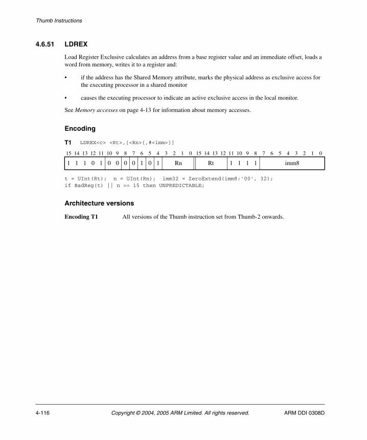
Thumb Instructions
4.6.51 LDREX
Load Register Exclusive calculates an address from a base register value and an immediate offset, loads a word from memory, writes it to a register and:
• if the address has the Shared Memory attribute, marks the physical address as exclusive access for the executing processor in a shared monitor
• causes the executing processor to indicate an active exclusive access in the local monitor.
See Memory accesses on page 4-13 for information about memory accesses.
Encoding
t = UInt(Rt); n = UInt(Rn); imm32 = ZeroExtend(imm8:'00', 32);if BadReg(t) || n == 15 then UNPREDICTABLE;
Architecture versions
Encoding T1 All versions of the Thumb instruction set from Thumb-2 onwards.
T1 LDREX<c> <Rt>,[<Rn>{,#<imm>}]
15 14 13 12 11 10 9 8 7 6 5 4 3 2 1 0 15 14 13 12 11 10 9 8 7 6 5 4 3 2 1 0
1 1 1 0 1 0 0 0 0 1 0 1 Rn Rt 1 1 1 1 imm8
4-116 Copyright © 2004, 2005 ARM Limited. All rights reserved. ARM DDI 0308D
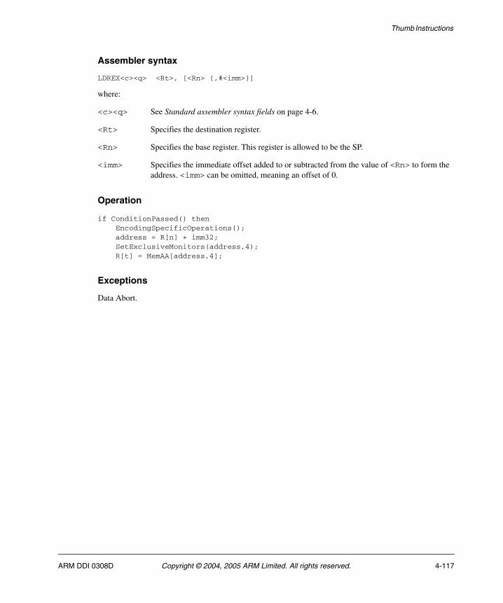
Thumb Instructions
Assembler syntax
LDREX<c><q> <Rt>, [<Rn> {,#<imm>}]
where:
<c><q> See Standard assembler syntax fields on page 4-6.
<Rt> Specifies the destination register.
<Rn> Specifies the base register. This register is allowed to be the SP.
<imm> Specifies the immediate offset added to or subtracted from the value of <Rn> to form the address. <imm> can be omitted, meaning an offset of 0.
Operation
if ConditionPassed() then EncodingSpecificOperations(); address = R[n] + imm32; SetExclusiveMonitors(address,4); R[t] = MemAA[address,4];
Exceptions
Data Abort.
ARM DDI 0308D Copyright © 2004, 2005 ARM Limited. All rights reserved. 4-117

Thumb Instructions
4.6.52 LDREXB
Load Register Exclusive Byte derives an address from a base register value, loads a byte from memory, zero-extends it to form a 32-bit word, writes it to a register and:
• if the address has the Shared Memory attribute, marks the physical address as exclusive access for the executing processor in a shared monitor
• causes the executing processor to indicate an active exclusive access in the local monitor.
See Memory accesses on page 4-13 for information about memory accesses.
Encoding
t = UInt(Rt); n = UInt(Rn);if BadReg(t) || n == 15 then UNPREDICTABLE;
Architecture versions
Encoding T1 All versions of the Thumb instruction set from v6K onwards.
T1 LDREXB<c> <Rt>, [<Rn>]
15 14 13 12 11 10 9 8 7 6 5 4 3 2 1 0 15 14 13 12 11 10 9 8 7 6 5 4 3 2 1 0
1 1 1 0 1 0 0 0 1 1 0 1 Rn Rt (1) (1) (1) (1) 0 1 0 0 (1) (1) (1) (1)
4-118 Copyright © 2004, 2005 ARM Limited. All rights reserved. ARM DDI 0308D
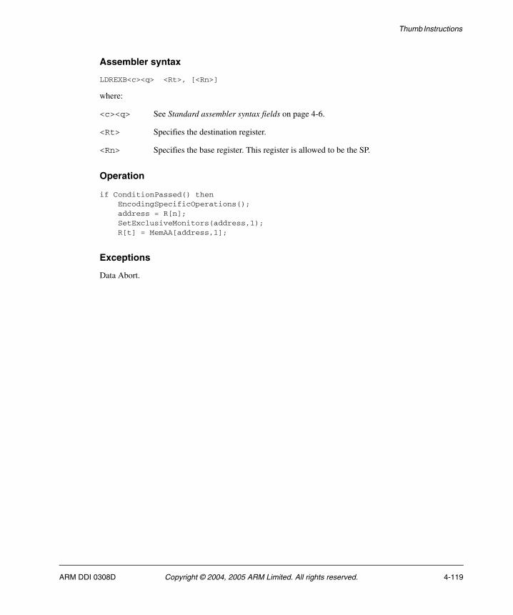
Thumb Instructions
Assembler syntax
LDREXB<c><q> <Rt>, [<Rn>]
where:
<c><q> See Standard assembler syntax fields on page 4-6.
<Rt> Specifies the destination register.
<Rn> Specifies the base register. This register is allowed to be the SP.
Operation
if ConditionPassed() then EncodingSpecificOperations(); address = R[n]; SetExclusiveMonitors(address,1); R[t] = MemAA[address,1];
Exceptions
Data Abort.
ARM DDI 0308D Copyright © 2004, 2005 ARM Limited. All rights reserved. 4-119
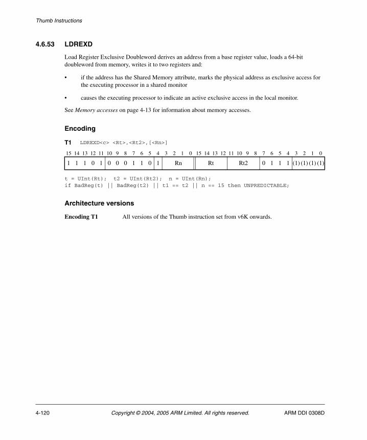
Thumb Instructions
4.6.53 LDREXD
Load Register Exclusive Doubleword derives an address from a base register value, loads a 64-bit doubleword from memory, writes it to two registers and:
• if the address has the Shared Memory attribute, marks the physical address as exclusive access for the executing processor in a shared monitor
• causes the executing processor to indicate an active exclusive access in the local monitor.
See Memory accesses on page 4-13 for information about memory accesses.
Encoding
t = UInt(Rt); t2 = UInt(Rt2); n = UInt(Rn);if BadReg(t) || BadReg(t2) || t1 == t2 || n == 15 then UNPREDICTABLE;
Architecture versions
Encoding T1 All versions of the Thumb instruction set from v6K onwards.
T1 LDREXD<c> <Rt>,<Rt2>,[<Rn>]
15 14 13 12 11 10 9 8 7 6 5 4 3 2 1 0 15 14 13 12 11 10 9 8 7 6 5 4 3 2 1 0
1 1 1 0 1 0 0 0 1 1 0 1 Rn Rt Rt2 0 1 1 1 (1) (1) (1) (1)
4-120 Copyright © 2004, 2005 ARM Limited. All rights reserved. ARM DDI 0308D

Thumb Instructions
Assembler syntax
LDREXD<c><q> <Rt>, [<Rn>]
where:
<c><q> See Standard assembler syntax fields on page 4-6.
<Rt> Specifies the destination register.
<Rn> Specifies the base register. This register is allowed to be the SP.
Operation
if ConditionPassed() then EncodingSpecificOperations(); address = R[n]; SetExclusiveMonitors(address,8); value = MemAA[address,8]; // Extract words from 64-bit loaded value such that R[t] is // loaded from address and R[t2] from address+4. if BigEndian() then R[t] = value<63:32>; // = contents of word at address R[t2] = value<31:0>; // = contents of word at address+4 else R[t] = value<31:0>; // = contents of word at address R[t2] = value<63:32>; // = contents of word at address+4
Exceptions
Data Abort.
ARM DDI 0308D Copyright © 2004, 2005 ARM Limited. All rights reserved. 4-121
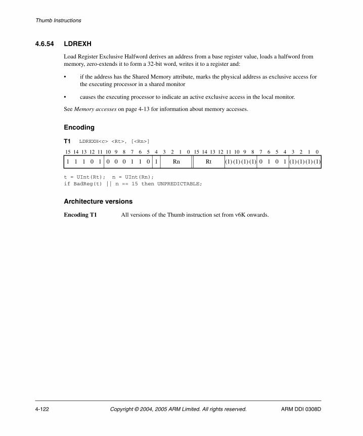
Thumb Instructions
4.6.54 LDREXH
Load Register Exclusive Halfword derives an address from a base register value, loads a halfword from memory, zero-extends it to form a 32-bit word, writes it to a register and:
• if the address has the Shared Memory attribute, marks the physical address as exclusive access for the executing processor in a shared monitor
• causes the executing processor to indicate an active exclusive access in the local monitor.
See Memory accesses on page 4-13 for information about memory accesses.
Encoding
t = UInt(Rt); n = UInt(Rn);if BadReg(t) || n == 15 then UNPREDICTABLE;
Architecture versions
Encoding T1 All versions of the Thumb instruction set from v6K onwards.
T1 LDREXH<c> <Rt>, [<Rn>]
15 14 13 12 11 10 9 8 7 6 5 4 3 2 1 0 15 14 13 12 11 10 9 8 7 6 5 4 3 2 1 0
1 1 1 0 1 0 0 0 1 1 0 1 Rn Rt (1) (1) (1) (1) 0 1 0 1 (1) (1) (1) (1)
4-122 Copyright © 2004, 2005 ARM Limited. All rights reserved. ARM DDI 0308D

Thumb Instructions
Assembler syntax
LDREXH<c><q> <Rt>, [<Rn>]
where:
<c><q> See Standard assembler syntax fields on page 4-6.
<Rt> Specifies the destination register.
<Rn> Specifies the base register. This register is allowed to be the SP.
Operation
if ConditionPassed() then EncodingSpecificOperations(); address = R[n]; SetExclusiveMonitors(address,2); R[t] = MemAA[address,2];
Exceptions
Data Abort.
ARM DDI 0308D Copyright © 2004, 2005 ARM Limited. All rights reserved. 4-123
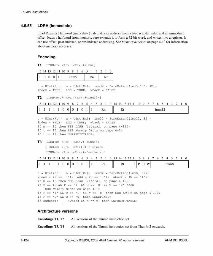
Thumb Instructions
4.6.55 LDRH (immediate)
Load Register Halfword (immediate) calculates an address from a base register value and an immediate offset, loads a halfword from memory, zero-extends it to form a 32-bit word, and writes it to a register. It can use offset, post-indexed, or pre-indexed addressing. See Memory accesses on page 4-13 for information about memory accesses.
Encoding
t = UInt(Rt); n = UInt(Rn); imm32 = ZeroExtend(imm5:'0', 32);index = TRUE; add = TRUE; wback = FALSE;
t = UInt(Rt); n = UInt(Rn); imm32 = ZeroExtend(imm12, 32);index = TRUE; add = TRUE; wback = FALSE;if n == 15 then SEE LDRH (literal) on page 4-126;if t == 15 then SEE Memory hints on page 4-14if t == 13 then UNPREDICTABLE;
t = UInt(Rt); n = UInt(Rn); imm32 = ZeroExtend(imm8, 32);index = (P == '1'); add = (U == '1'); wback = (W == '1');if n == 15 then SEE LDRH (literal) on page 4-126;if t == 15 && P == '1' && U == '0' && W == '0' then SEE Memory hints on page 4-14if P == '1' && U == '1' && W == '0' then SEE LDRHT on page 4-130;if P == '0' && W == '0' then UNDEFINED;if BadReg(t) || (wback && n == t) then UNPREDICTABLE;
Architecture versions
Encodings T1, T2 All versions of the Thumb instruction set.
Encodings T3, T4 All versions of the Thumb instruction set from Thumb-2 onwards.
T1 LDRH<c> <Rt>,[<Rn>,#<imm>]
15 14 13 12 11 10 9 8 7 6 5 4 3 2 1 0
1 0 0 0 1 imm5 Rn Rt
T2 LDRH<c>.W <Rt,[<Rn>,#<imm12>]
15 14 13 12 11 10 9 8 7 6 5 4 3 2 1 0 15 14 13 12 11 10 9 8 7 6 5 4 3 2 1 0
1 1 1 1 1 0 0 0 1 0 1 1 Rn Rt imm12
T3 LDRH<c> <Rt>,[<Rn>,#-<imm8>]
LDRH<c> <Rt>,[<Rn>],#+/-<imm8>
LDRH<c> <Rt>,[<Rn>,#+/-<imm8>]!
15 14 13 12 11 10 9 8 7 6 5 4 3 2 1 0 15 14 13 12 11 10 9 8 7 6 5 4 3 2 1 0
1 1 1 1 1 0 0 0 0 0 1 1 Rn Rt 1 P U W imm8
4-124 Copyright © 2004, 2005 ARM Limited. All rights reserved. ARM DDI 0308D

Thumb Instructions
Assembler syntax
where:
<c><q> See Standard assembler syntax fields on page 4-6.
<Rt> Specifies the destination register.
<Rn> Specifies the base register. This register is allowed to be the SP. If this register is the PC, see LDRH (literal) on page 4-126.
+/- Is + or omitted to indicate that the immediate offset is added to the base register value (add == TRUE), or – to indicate that the offset is to be subtracted (add == FALSE). Different instructions are generated for #0 and #-0.
<imm> Specifies the immediate offset added to or subtracted from the value of <Rn> to form the address. For the offset addressing syntax, <imm> can be omitted, meaning an offset of 0.
The pre-UAL syntax LDR<c>H is equivalent to LDRH<c>.
Operation
if ConditionPassed() then EncodingSpecificOperations(); offset_addr = if add then (R[n] + imm32) else (R[n] - imm32); address = if index then offset_addr else R[n]; if wback then R[n] = offset_addr; R[t] = ZeroExtend(MemU[address,2], 32);
Exceptions
Data Abort.
LDRH<c><q> <Rt>, [<Rn> {, #+/-<imm>}] Offset: index==TRUE, wback==FALSELDRH<c><q> <Rt>, [<Rn>, #+/-<imm>]! Pre-indexed: index==TRUE, wback==TRUELDRH<c><q> <Rt>, [<Rn>], #+/-<imm> Post-indexed: index==FALSE, wback==TRUE
ARM DDI 0308D Copyright © 2004, 2005 ARM Limited. All rights reserved. 4-125
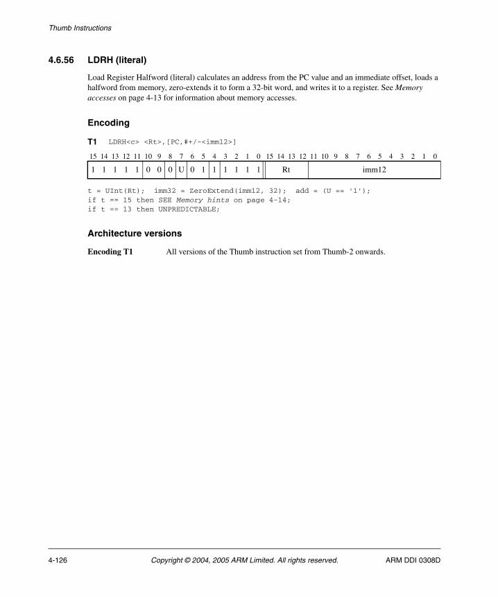
Thumb Instructions
4.6.56 LDRH (literal)
Load Register Halfword (literal) calculates an address from the PC value and an immediate offset, loads a halfword from memory, zero-extends it to form a 32-bit word, and writes it to a register. See Memory accesses on page 4-13 for information about memory accesses.
Encoding
t = UInt(Rt); imm32 = ZeroExtend(imm12, 32); add = (U == '1');if t == 15 then SEE Memory hints on page 4-14;if t == 13 then UNPREDICTABLE;
Architecture versions
Encoding T1 All versions of the Thumb instruction set from Thumb-2 onwards.
T1 LDRH<c> <Rt>,[PC,#+/-<imm12>]
15 14 13 12 11 10 9 8 7 6 5 4 3 2 1 0 15 14 13 12 11 10 9 8 7 6 5 4 3 2 1 0
1 1 1 1 1 0 0 0 U 0 1 1 1 1 1 1 Rt imm12
4-126 Copyright © 2004, 2005 ARM Limited. All rights reserved. ARM DDI 0308D
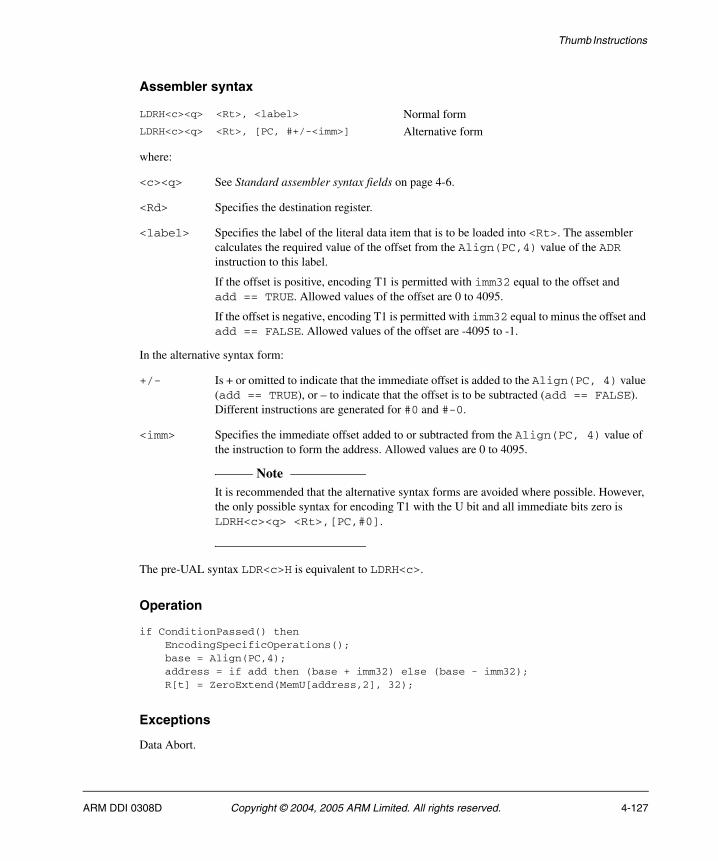
Thumb Instructions
Assembler syntax
where:
<c><q> See Standard assembler syntax fields on page 4-6.
<Rd> Specifies the destination register.
<label> Specifies the label of the literal data item that is to be loaded into <Rt>. The assembler calculates the required value of the offset from the Align(PC,4) value of the ADR instruction to this label.
If the offset is positive, encoding T1 is permitted with imm32 equal to the offset and add == TRUE. Allowed values of the offset are 0 to 4095.
If the offset is negative, encoding T1 is permitted with imm32 equal to minus the offset and add == FALSE. Allowed values of the offset are -4095 to -1.
In the alternative syntax form:
+/- Is + or omitted to indicate that the immediate offset is added to the Align(PC, 4) value (add == TRUE), or – to indicate that the offset is to be subtracted (add == FALSE). Different instructions are generated for #0 and #-0.
<imm> Specifies the immediate offset added to or subtracted from the Align(PC, 4) value of the instruction to form the address. Allowed values are 0 to 4095.
Note It is recommended that the alternative syntax forms are avoided where possible. However,
the only possible syntax for encoding T1 with the U bit and all immediate bits zero is LDRH<c><q> <Rt>,[PC,#0].
The pre-UAL syntax LDR<c>H is equivalent to LDRH<c>.
Operation
if ConditionPassed() then EncodingSpecificOperations(); base = Align(PC,4); address = if add then (base + imm32) else (base - imm32); R[t] = ZeroExtend(MemU[address,2], 32);
Exceptions
Data Abort.
LDRH<c><q> <Rt>, <label> Normal formLDRH<c><q> <Rt>, [PC, #+/-<imm>] Alternative form
ARM DDI 0308D Copyright © 2004, 2005 ARM Limited. All rights reserved. 4-127

Thumb Instructions
4.6.57 LDRH (register)
Load Register Halfword (register) calculates an address from a base register value and an offset register value, loads a halfword from memory, zero-extends it to form a 32-bit word, and writes it to a register. The offset register value can be shifted left by 0, 1, 2, or 3 bits. See Memory accesses on page 4-13 for information about memory accesses.
Encoding
t = UInt(Rt); n = UInt(Rn); m = UInt(Rm);(shift_t, shift_n) = (SRType_None, 0);
t = UInt(Rt); n = UInt(Rn); m = UInt(Rm);(shift_t, shift_n) = (SRType_LSL, UInt(shift));if n == 15 then SEE LDRH (literal) on page 4-126;if t == 15 then SEE Memory hints on page 4-14;if t == 13 || BadReg(m) then UNPREDICTABLE;;
Architecture versions
Encoding T1 All versions of the Thumb instruction set.
Encoding T2 All versions of the Thumb instruction set from Thumb-2 onwards.
T1 LDRH<c> <Rt>,[<Rn>,<Rm>]
15 14 13 12 11 10 9 8 7 6 5 4 3 2 1 0
0 1 0 1 1 0 1 Rm Rn Rt
T2 LDRH<c>.W <Rt>,[<Rn>,<Rm>{,LSL #<shift>}]
15 14 13 12 11 10 9 8 7 6 5 4 3 2 1 0 15 14 13 12 11 10 9 8 7 6 5 4 3 2 1 0
1 1 1 1 1 0 0 0 0 0 1 1 Rn Rt 0 0 0 0 0 0 shift Rm
4-128 Copyright © 2004, 2005 ARM Limited. All rights reserved. ARM DDI 0308D

Thumb Instructions
Assembler syntax
LDRH<c><q> <Rt>, [<Rn>, <Rm> {, LSL #<shift>}]
where:
<c><q> See Standard assembler syntax fields on page 4-6.
<Rn> Specifies the register that contains the base value. This register is allowed to be the SP.
<Rm> Contains the offset that is shifted left and added to the value of <Rn> to form the address.
<shift> Specifies the number of bits the value from <Rm> is shifted left, in the range 0-3. If this option is omitted, a shift by 0 is assumed and both encodings are permitted. If this option is specified, only encoding T2 is permitted.
The pre-UAL syntax LDR<c>H is equivalent to LDRH<c>.
Operation
if ConditionPassed() then EncodingSpecificOperations(); address = R[n] + LSL(R[m], shift_n); R[t] = ZeroExtend(MemU[address,2], 32);
Exceptions
Data Abort.
ARM DDI 0308D Copyright © 2004, 2005 ARM Limited. All rights reserved. 4-129

Thumb Instructions
4.6.58 LDRHT
Load Register Halfword Unprivileged calculates an address from a base register value and an immediate offset, loads a halfword from memory, zero-extends it to form a 32-bit word, and writes it to a register. See Memory accesses on page 4-13 for information about memory accesses.
The memory access is restricted as if the processor were running in User mode. (This makes no difference if the processor is actually running in User mode.)
Encoding
t = UInt(Rt); n = UInt(Rn); imm32 = ZeroExtend(imm8, 32);if n == 15 then SEE LDRH (literal) on page 4-126;if BadReg(t) then UNPREDICTABLE;
Architecture versions
Encoding T1 All versions of the Thumb instruction set from Thumb-2 onwards.
T1 LDRHT<c> <Rt>,[<Rn>,#<imm8>]
15 14 13 12 11 10 9 8 7 6 5 4 3 2 1 0 15 14 13 12 11 10 9 8 7 6 5 4 3 2 1 0
1 1 1 1 1 0 0 0 0 0 1 1 Rn Rt 1 1 1 0 imm8
4-130 Copyright © 2004, 2005 ARM Limited. All rights reserved. ARM DDI 0308D

Thumb Instructions
Assembler syntax
LDRHT<c><q> <Rt>, [<Rn> {, #<imm>}]
where:
<c><q> See Standard assembler syntax fields on page 4-6.
<Rt> Specifies the destination register.
<Rn> Specifies the base register. This register is allowed to be the SP.
<imm> Specifies the immediate offset added to the value of <Rn> to form the address. <imm> can be omitted, meaning an offset of 0.
Operation
if ConditionPassed() then EncodingSpecificOperations(); address = R[n] + imm32; R[t] = ZeroExtend(MemU_unpriv[address,2], 32);
Exceptions
Data Abort.
ARM DDI 0308D Copyright © 2004, 2005 ARM Limited. All rights reserved. 4-131
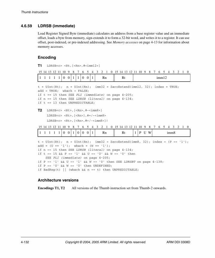
Thumb Instructions
4.6.59 LDRSB (immediate)
Load Register Signed Byte (immediate) calculates an address from a base register value and an immediate offset, loads a byte from memory, sign-extends it to form a 32-bit word, and writes it to a register. It can use offset, post-indexed, or pre-indexed addressing. See Memory accesses on page 4-13 for information about memory accesses.
Encoding
t = UInt(Rt); n = UInt(Rn); imm32 = ZeroExtend(imm12, 32); index = TRUE;add = TRUE; wback = FALSE; if t == 15 then SEE PLI (immediate) on page 4-205; if n == 15 then SEE LDRSB (literal) on page 4-134; if t == 13 then UNPREDICTABLE;
t = UInt(Rt); n = UInt(Rn); imm32 = ZeroExtend(imm8, 32); index = (P == '1');add = (U == '1'); wback = (W == '1'); if n == 15 then SEE LDRSB (literal) on page 4-134; if t == 15 && P == '1' && U == '0' && W == '0' then SEE PLI (immediate) on page 4-205;if P == '1' && U == '1' && W == '0' then SEE LDRSBT on page 4-138; if P == '0' && W == '0' then UNDEFINED; if BadReg(t) || (wback && n == t) then UNPREDICTABLE;
Architecture versions
Encodings T1, T2 All versions of the Thumb instruction set from Thumb-2 onwards.
T1 LDRSB<c> <Rt,[<Rn>,#<imm12>]
15 14 13 12 11 10 9 8 7 6 5 4 3 2 1 0 15 14 13 12 11 10 9 8 7 6 5 4 3 2 1 0
1 1 1 1 1 0 0 1 1 0 0 1 Rn Rt imm12
T2 LDRSB<c> <Rt>,[<Rn>,#-<imm8>]
LDRSB<c> <Rt>,[<Rn>],#+/-<imm8>
LDRSB<c> <Rt>,[<Rn>,#+/-<imm8>]!
15 14 13 12 11 10 9 8 7 6 5 4 3 2 1 0 15 14 13 12 11 10 9 8 7 6 5 4 3 2 1 0
1 1 1 1 1 0 0 1 0 0 0 1 Rn Rt 1 P U W imm8
4-132 Copyright © 2004, 2005 ARM Limited. All rights reserved. ARM DDI 0308D
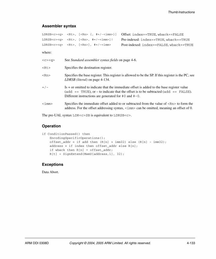
Thumb Instructions
Assembler syntax
where:
<c><q> See Standard assembler syntax fields on page 4-6.
<Rt> Specifies the destination register.
<Rn> Specifies the base register. This register is allowed to be the SP. If this register is the PC, see LDRSB (literal) on page 4-134.
+/- Is + or omitted to indicate that the immediate offset is added to the base register value (add == TRUE), or – to indicate that the offset is to be subtracted (add == FALSE). Different instructions are generated for #0 and #-0.
<imm> Specifies the immediate offset added to or subtracted from the value of <Rn> to form the address. For the offset addressing syntax, <imm> can be omitted, meaning an offset of 0.
The pre-UAL syntax LDR<c>SB is equivalent to LDRSB<c>.
Operation
if ConditionPassed() then EncodingSpecificOperations(); offset_addr = if add then (R[n] + imm32) else (R[n] - imm32); address = if index then offset_addr else R[n]; if wback then R[n] = offset_addr; R[t] = SignExtend(MemU[address,1], 32);
Exceptions
Data Abort.
LDRSB<c><q> <Rt>, [<Rn> {, #+/-<imm>}] Offset: index==TRUE, wback==FALSELDRSB<c><q> <Rt>, [<Rn>, #+/-<imm>]! Pre-indexed: index==TRUE, wback==TRUELDRSB<c><q> <Rt>, [<Rn>], #+/-<imm> Post-indexed: index==FALSE, wback==TRUE
ARM DDI 0308D Copyright © 2004, 2005 ARM Limited. All rights reserved. 4-133

Thumb Instructions
4.6.60 LDRSB (literal)
Load Register Signed Byte (literal) calculates an address from the PC value and an immediate offset, loads a byte from memory, sign-extends it to form a 32-bit word, and writes it to a register. See Memory accesses on page 4-13 for information about memory accesses.
Encoding
t = UInt(Rt); imm32 = ZeroExtend(imm12, 32); add = (U == '1'); if t == 15 then SEE PLI (immediate) on page 4-205; if t == 13 then UNPREDICTABLE;
Architecture versions
Encoding T1 All versions of the Thumb instruction set from Thumb-2 onwards.
T1 LDRSB<c> <Rt>,[PC,#+/-<imm12>]
15 14 13 12 11 10 9 8 7 6 5 4 3 2 1 0 15 14 13 12 11 10 9 8 7 6 5 4 3 2 1 0
1 1 1 1 1 0 0 1 U 0 0 1 1 1 1 1 Rt imm12
4-134 Copyright © 2004, 2005 ARM Limited. All rights reserved. ARM DDI 0308D
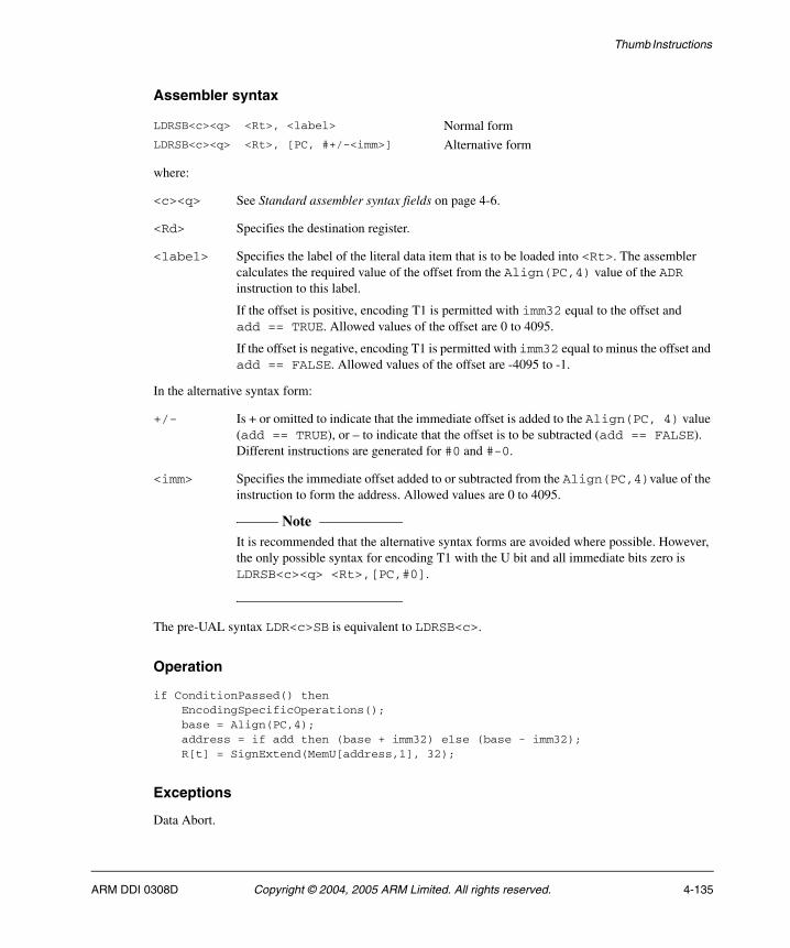
Thumb Instructions
Assembler syntax
where:
<c><q> See Standard assembler syntax fields on page 4-6.
<Rd> Specifies the destination register.
<label> Specifies the label of the literal data item that is to be loaded into <Rt>. The assembler calculates the required value of the offset from the Align(PC,4) value of the ADR instruction to this label.
If the offset is positive, encoding T1 is permitted with imm32 equal to the offset and add == TRUE. Allowed values of the offset are 0 to 4095.
If the offset is negative, encoding T1 is permitted with imm32 equal to minus the offset and add == FALSE. Allowed values of the offset are -4095 to -1.
In the alternative syntax form:
+/- Is + or omitted to indicate that the immediate offset is added to the Align(PC, 4) value (add == TRUE), or – to indicate that the offset is to be subtracted (add == FALSE). Different instructions are generated for #0 and #-0.
<imm> Specifies the immediate offset added to or subtracted from the Align(PC,4)value of the instruction to form the address. Allowed values are 0 to 4095.
Note It is recommended that the alternative syntax forms are avoided where possible. However,
the only possible syntax for encoding T1 with the U bit and all immediate bits zero is LDRSB<c><q> <Rt>,[PC,#0].
The pre-UAL syntax LDR<c>SB is equivalent to LDRSB<c>.
Operation
if ConditionPassed() then EncodingSpecificOperations(); base = Align(PC,4); address = if add then (base + imm32) else (base - imm32); R[t] = SignExtend(MemU[address,1], 32);
Exceptions
Data Abort.
LDRSB<c><q> <Rt>, <label> Normal formLDRSB<c><q> <Rt>, [PC, #+/-<imm>] Alternative form
ARM DDI 0308D Copyright © 2004, 2005 ARM Limited. All rights reserved. 4-135
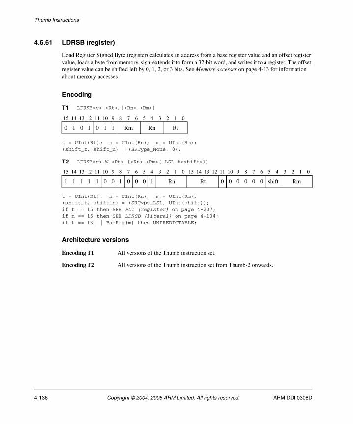
Thumb Instructions
4.6.61 LDRSB (register)
Load Register Signed Byte (register) calculates an address from a base register value and an offset register value, loads a byte from memory, sign-extends it to form a 32-bit word, and writes it to a register. The offset register value can be shifted left by 0, 1, 2, or 3 bits. See Memory accesses on page 4-13 for information about memory accesses.
Encoding
t = UInt(Rt); n = UInt(Rn); m = UInt(Rm);(shift_t, shift_n) = (SRType_None, 0);
t = UInt(Rt); n = UInt(Rn); m = UInt(Rm); (shift_t, shift_n) = (SRType_LSL, UInt(shift)); if t == 15 then SEE PLI (register) on page 4-207; if n == 15 then SEE LDRSB (literal) on page 4-134; if t == 13 || BadReg(m) then UNPREDICTABLE;
Architecture versions
Encoding T1 All versions of the Thumb instruction set.
Encoding T2 All versions of the Thumb instruction set from Thumb-2 onwards.
T1 LDRSB<c> <Rt>,[<Rn>,<Rm>]
15 14 13 12 11 10 9 8 7 6 5 4 3 2 1 0
0 1 0 1 0 1 1 Rm Rn Rt
T2 LDRSB<c>.W <Rt>,[<Rn>,<Rm>{,LSL #<shift>}]
15 14 13 12 11 10 9 8 7 6 5 4 3 2 1 0 15 14 13 12 11 10 9 8 7 6 5 4 3 2 1 0
1 1 1 1 1 0 0 1 0 0 0 1 Rn Rt 0 0 0 0 0 0 shift Rm
4-136 Copyright © 2004, 2005 ARM Limited. All rights reserved. ARM DDI 0308D
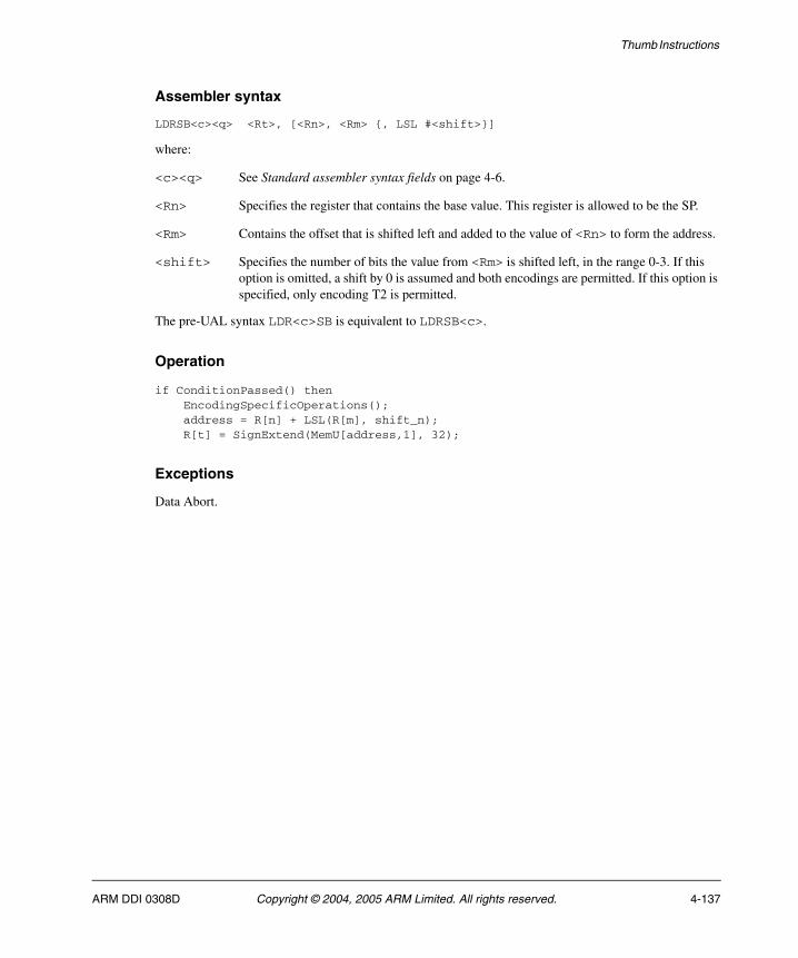
Thumb Instructions
Assembler syntax
LDRSB<c><q> <Rt>, [<Rn>, <Rm> {, LSL #<shift>}]
where:
<c><q> See Standard assembler syntax fields on page 4-6.
<Rn> Specifies the register that contains the base value. This register is allowed to be the SP.
<Rm> Contains the offset that is shifted left and added to the value of <Rn> to form the address.
<shift> Specifies the number of bits the value from <Rm> is shifted left, in the range 0-3. If this option is omitted, a shift by 0 is assumed and both encodings are permitted. If this option is specified, only encoding T2 is permitted.
The pre-UAL syntax LDR<c>SB is equivalent to LDRSB<c>.
Operation
if ConditionPassed() then EncodingSpecificOperations(); address = R[n] + LSL(R[m], shift_n); R[t] = SignExtend(MemU[address,1], 32);
Exceptions
Data Abort.
ARM DDI 0308D Copyright © 2004, 2005 ARM Limited. All rights reserved. 4-137
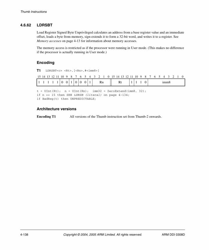
Thumb Instructions
4.6.62 LDRSBT
Load Register Signed Byte Unprivileged calculates an address from a base register value and an immediate offset, loads a byte from memory, sign-extends it to form a 32-bit word, and writes it to a register. See Memory accesses on page 4-13 for information about memory accesses.
The memory access is restricted as if the processor were running in User mode. (This makes no difference if the processor is actually running in User mode.)
Encoding
t = UInt(Rt); n = UInt(Rn); imm32 = ZeroExtend(imm8, 32);if n == 15 then SEE LDRSB (literal) on page 4-134;if BadReg(t) then UNPREDICTABLE;
Architecture versions
Encoding T1 All versions of the Thumb instruction set from Thumb-2 onwards.
T1 LDRSBT<c> <Rt>,[<Rn>,#<imm8>]
15 14 13 12 11 10 9 8 7 6 5 4 3 2 1 0 15 14 13 12 11 10 9 8 7 6 5 4 3 2 1 0
1 1 1 1 1 0 0 1 0 0 0 1 Rn Rt 1 1 1 0 imm8
4-138 Copyright © 2004, 2005 ARM Limited. All rights reserved. ARM DDI 0308D
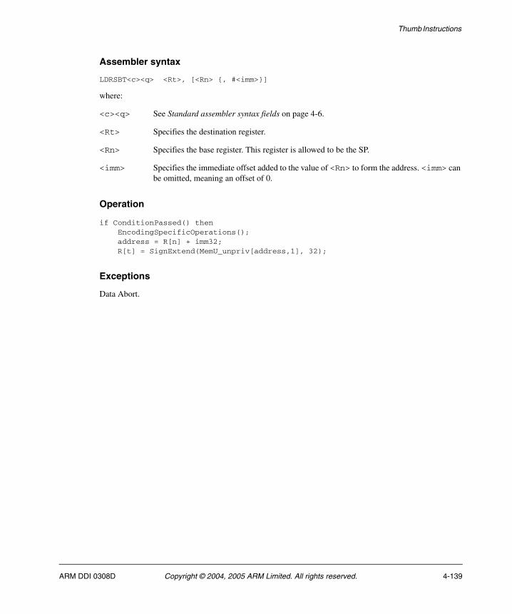
Thumb Instructions
Assembler syntax
LDRSBT<c><q> <Rt>, [<Rn> {, #<imm>}]
where:
<c><q> See Standard assembler syntax fields on page 4-6.
<Rt> Specifies the destination register.
<Rn> Specifies the base register. This register is allowed to be the SP.
<imm> Specifies the immediate offset added to the value of <Rn> to form the address. <imm> can be omitted, meaning an offset of 0.
Operation
if ConditionPassed() then EncodingSpecificOperations(); address = R[n] + imm32; R[t] = SignExtend(MemU_unpriv[address,1], 32);
Exceptions
Data Abort.
ARM DDI 0308D Copyright © 2004, 2005 ARM Limited. All rights reserved. 4-139
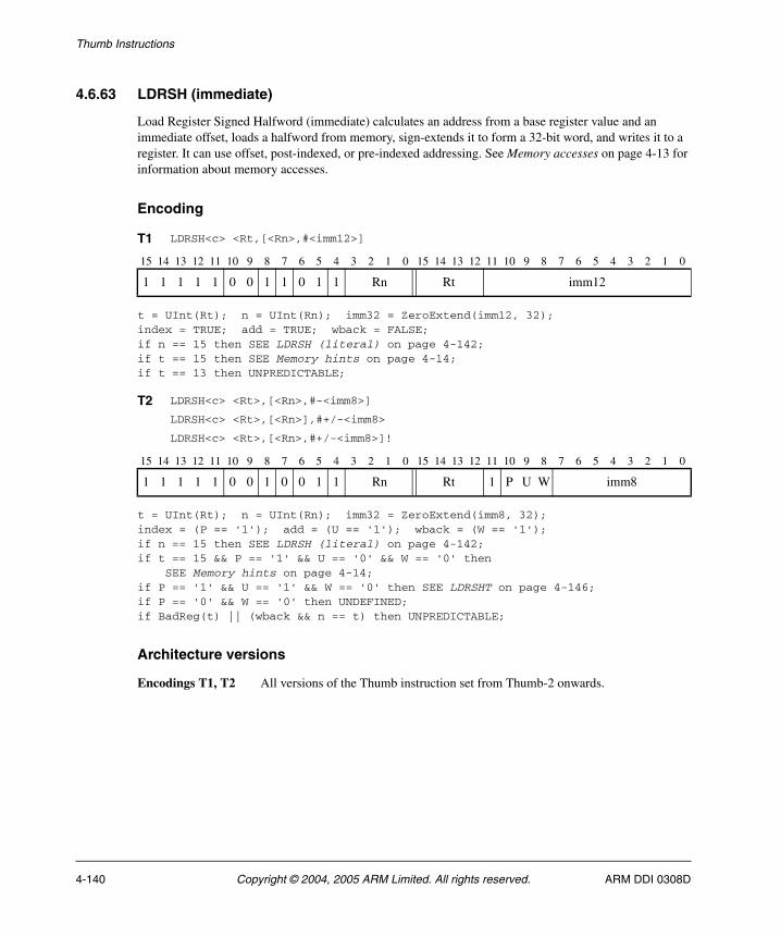
Thumb Instructions
4.6.63 LDRSH (immediate)
Load Register Signed Halfword (immediate) calculates an address from a base register value and an immediate offset, loads a halfword from memory, sign-extends it to form a 32-bit word, and writes it to a register. It can use offset, post-indexed, or pre-indexed addressing. See Memory accesses on page 4-13 for information about memory accesses.
Encoding
t = UInt(Rt); n = UInt(Rn); imm32 = ZeroExtend(imm12, 32);index = TRUE; add = TRUE; wback = FALSE;if n == 15 then SEE LDRSH (literal) on page 4-142;if t == 15 then SEE Memory hints on page 4-14;if t == 13 then UNPREDICTABLE;
t = UInt(Rt); n = UInt(Rn); imm32 = ZeroExtend(imm8, 32);index = (P == '1'); add = (U == '1'); wback = (W == '1');if n == 15 then SEE LDRSH (literal) on page 4-142;if t == 15 && P == '1' && U == '0' && W == '0' then SEE Memory hints on page 4-14;if P == '1' && U == '1' && W == '0' then SEE LDRSHT on page 4-146;if P == '0' && W == '0' then UNDEFINED;if BadReg(t) || (wback && n == t) then UNPREDICTABLE;
Architecture versions
Encodings T1, T2 All versions of the Thumb instruction set from Thumb-2 onwards.
T1 LDRSH<c> <Rt,[<Rn>,#<imm12>]
15 14 13 12 11 10 9 8 7 6 5 4 3 2 1 0 15 14 13 12 11 10 9 8 7 6 5 4 3 2 1 0
1 1 1 1 1 0 0 1 1 0 1 1 Rn Rt imm12
T2 LDRSH<c> <Rt>,[<Rn>,#-<imm8>]
LDRSH<c> <Rt>,[<Rn>],#+/-<imm8>
LDRSH<c> <Rt>,[<Rn>,#+/-<imm8>]!
15 14 13 12 11 10 9 8 7 6 5 4 3 2 1 0 15 14 13 12 11 10 9 8 7 6 5 4 3 2 1 0
1 1 1 1 1 0 0 1 0 0 1 1 Rn Rt 1 P U W imm8
4-140 Copyright © 2004, 2005 ARM Limited. All rights reserved. ARM DDI 0308D

Thumb Instructions
Assembler syntax
where:
<c><q> See Standard assembler syntax fields on page 4-6.
<Rt> Specifies the destination register.
<Rn> Specifies the base register. This register is allowed to be the SP. If this register is the PC, see LDRSH (literal) on page 4-142.
+/- Is + or omitted to indicate that the immediate offset is added to the base register value (add == TRUE), or – to indicate that the offset is to be subtracted (add == FALSE). Different instructions are generated for #0 and #-0.
<imm> Specifies the immediate offset added to or subtracted from the value of <Rn> to form the address. For the offset addressing syntax, <imm> can be omitted, meaning an offset of 0.
The pre-UAL syntax LDR<c>SH is equivalent to LDRSH<c>.
Operation
if ConditionPassed() then EncodingSpecificOperations(); offset_addr = if add then (R[n] + imm32) else (R[n] - imm32); address = if index then offset_addr else R[n]; if wback then R[n] = offset_addr; R[t] = SignExtend(MemU[address,2], 32);
Exceptions
Data Abort.
LDRSH<c><q> <Rt>, [<Rn> {, #+/-<imm>}] Offset: index==TRUE, wback==FALSELDRSH<c><q> <Rt>, [<Rn>, #+/-<imm>]! Pre-indexed: index==TRUE, wback==TRUELDRSH<c><q> <Rt>, [<Rn>], #+/-<imm> Post-indexed: index==FALSE, wback==TRUE
ARM DDI 0308D Copyright © 2004, 2005 ARM Limited. All rights reserved. 4-141
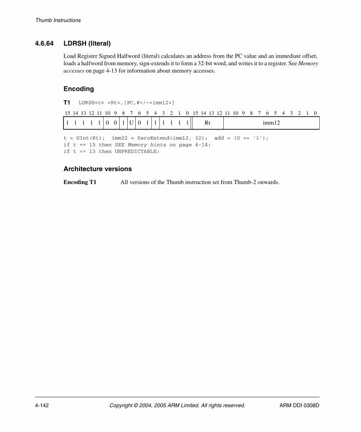
Thumb Instructions
4.6.64 LDRSH (literal)
Load Register Signed Halfword (literal) calculates an address from the PC value and an immediate offset, loads a halfword from memory, sign-extends it to form a 32-bit word, and writes it to a register. See Memory accesses on page 4-13 for information about memory accesses.
Encoding
t = UInt(Rt); imm32 = ZeroExtend(imm12, 32); add = (U == '1');if t == 15 then SEE Memory hints on page 4-14;if t == 13 then UNPREDICTABLE;
Architecture versions
Encoding T1 All versions of the Thumb instruction set from Thumb-2 onwards.
T1 LDRSH<c> <Rt>,[PC,#+/-<imm12>]
15 14 13 12 11 10 9 8 7 6 5 4 3 2 1 0 15 14 13 12 11 10 9 8 7 6 5 4 3 2 1 0
1 1 1 1 1 0 0 1 U 0 1 1 1 1 1 1 Rt imm12
4-142 Copyright © 2004, 2005 ARM Limited. All rights reserved. ARM DDI 0308D

Thumb Instructions
Assembler syntax
where:
<c><q> See Standard assembler syntax fields on page 4-6.
<Rd> Specifies the destination register.
<label> Specifies the label of the literal data item that is to be loaded into <Rt>. The assembler calculates the required value of the offset from the Align(PC,4) value of the ADR instruction to this label.
If the offset is positive, encoding T1 is permitted with imm32 equal to the offset and add == TRUE. Allowed values of the offset are 0 to 4095.
If the offset is negative, encoding T1 is permitted with imm32 equal to minus the offset and add == FALSE. Allowed values of the offset are -4095 to -1.
In the alternative syntax form:
+/- Is + or omitted to indicate that the immediate offset is added to the Align(PC, 4) value (add == TRUE), or – to indicate that the offset is to be subtracted (add == FALSE). Different instructions are generated for #0 and #-0.
<imm> Specifies the immediate offset added to or subtracted from the Align(PC, 4)value of the instruction to form the address. Allowed values are 0 to 4095.
Note It is recommended that the alternative syntax forms are avoided where possible. However,
the only possible syntax for encoding T1 with the U bit and all immediate bits zero is LDRSH<c><q> <Rt>,[PC,#0].
The pre-UAL syntax LDR<c>SH is equivalent to LDRSH<c>.
Operation
if ConditionPassed() then EncodingSpecificOperations(); base = Align(PC,4); address = if add then (base + imm32) else (base - imm32); R[t] = SignExtend(MemU[address,2], 32);
Exceptions
Data Abort.
LDRSH<c><q> <Rt>, <label> Normal formLDRSH<c><q> <Rt>, [PC, #+/-<imm>] Alternative form
ARM DDI 0308D Copyright © 2004, 2005 ARM Limited. All rights reserved. 4-143
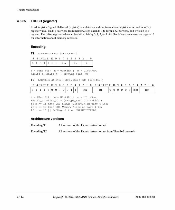
Thumb Instructions
4.6.65 LDRSH (register)
Load Register Signed Halfword (register) calculates an address from a base register value and an offset register value, loads a halfword from memory, sign-extends it to form a 32-bit word, and writes it to a register. The offset register value can be shifted left by 0, 1, 2, or 3 bits. See Memory accesses on page 4-13 for information about memory accesses.
Encoding
t = UInt(Rt); n = UInt(Rn); m = UInt(Rm);(shift_t, shift_n) = (SRType_None, 0);
t = UInt(Rt); n = UInt(Rn); m = UInt(Rm);(shift_t, shift_n) = (SRType_LSL, UInt(shift));if n == 15 then SEE LDRSH (literal) on page 4-142;if t == 15 then SEE Memory hints on page 4-14;if t == 13 || BadReg(m) then UNPREDICTABLE;
Architecture versions
Encoding T1 All versions of the Thumb instruction set.
Encoding T2 All versions of the Thumb instruction set from Thumb-2 onwards.
T1 LDRSH<c> <Rt>,[<Rn>,<Rm>]
15 14 13 12 11 10 9 8 7 6 5 4 3 2 1 0
0 1 0 1 1 1 1 Rm Rn Rt
T2 LDRSH<c>.W <Rt>,[<Rn>,<Rm>{,LSL #<shift>}]
15 14 13 12 11 10 9 8 7 6 5 4 3 2 1 0 15 14 13 12 11 10 9 8 7 6 5 4 3 2 1 0
1 1 1 1 1 0 0 1 0 0 1 1 Rn Rt 0 0 0 0 0 0 shift Rm
4-144 Copyright © 2004, 2005 ARM Limited. All rights reserved. ARM DDI 0308D
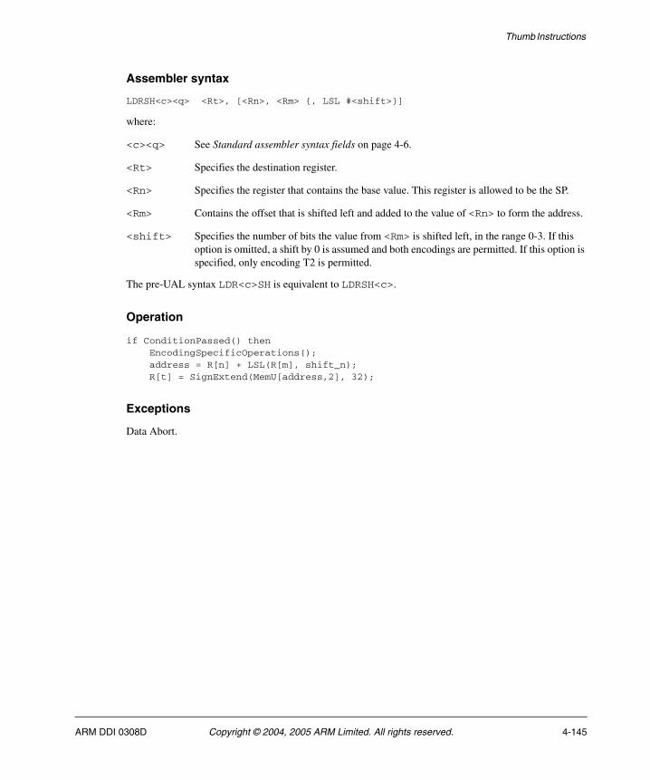
Thumb Instructions
Assembler syntax
LDRSH<c><q> <Rt>, [<Rn>, <Rm> {, LSL #<shift>}]
where:
<c><q> See Standard assembler syntax fields on page 4-6.
<Rt> Specifies the destination register.
<Rn> Specifies the register that contains the base value. This register is allowed to be the SP.
<Rm> Contains the offset that is shifted left and added to the value of <Rn> to form the address.
<shift> Specifies the number of bits the value from <Rm> is shifted left, in the range 0-3. If this option is omitted, a shift by 0 is assumed and both encodings are permitted. If this option is specified, only encoding T2 is permitted.
The pre-UAL syntax LDR<c>SH is equivalent to LDRSH<c>.
Operation
if ConditionPassed() then EncodingSpecificOperations(); address = R[n] + LSL(R[m], shift_n); R[t] = SignExtend(MemU[address,2], 32);
Exceptions
Data Abort.
ARM DDI 0308D Copyright © 2004, 2005 ARM Limited. All rights reserved. 4-145
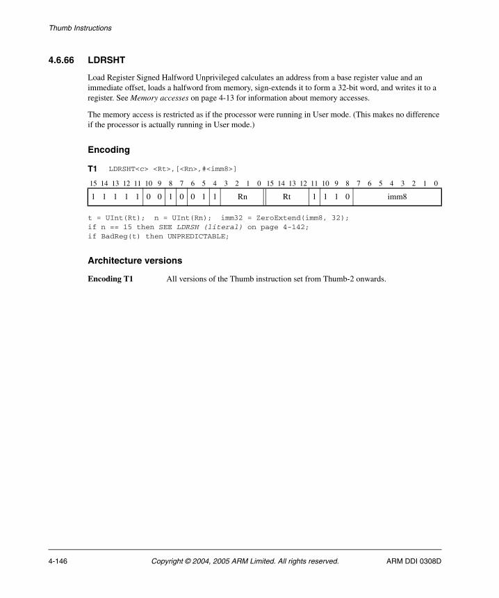
Thumb Instructions
4.6.66 LDRSHT
Load Register Signed Halfword Unprivileged calculates an address from a base register value and an immediate offset, loads a halfword from memory, sign-extends it to form a 32-bit word, and writes it to a register. See Memory accesses on page 4-13 for information about memory accesses.
The memory access is restricted as if the processor were running in User mode. (This makes no difference if the processor is actually running in User mode.)
Encoding
t = UInt(Rt); n = UInt(Rn); imm32 = ZeroExtend(imm8, 32);if n == 15 then SEE LDRSH (literal) on page 4-142;if BadReg(t) then UNPREDICTABLE;
Architecture versions
Encoding T1 All versions of the Thumb instruction set from Thumb-2 onwards.
T1 LDRSHT<c> <Rt>,[<Rn>,#<imm8>]
15 14 13 12 11 10 9 8 7 6 5 4 3 2 1 0 15 14 13 12 11 10 9 8 7 6 5 4 3 2 1 0
1 1 1 1 1 0 0 1 0 0 1 1 Rn Rt 1 1 1 0 imm8
4-146 Copyright © 2004, 2005 ARM Limited. All rights reserved. ARM DDI 0308D

Thumb Instructions
Assembler syntax
LDRSHT<c><q> <Rt>, [<Rn> {, #<imm>}]
where:
<c><q> See Standard assembler syntax fields on page 4-6.
<Rt> Specifies the destination register.
<Rn> Specifies the base register. This register is allowed to be the SP.
<imm> Specifies the immediate offset added to the value of <Rn> to form the address. <imm> can be omitted, meaning an offset of 0.
Operation
if ConditionPassed() then EncodingSpecificOperations(); address = R[n] + imm32; R[t] = SignExtend(MemU_unpriv[address,2], 32);
Exceptions
Data Abort.
ARM DDI 0308D Copyright © 2004, 2005 ARM Limited. All rights reserved. 4-147

Thumb Instructions
4.6.67 LDRT
Load Register Unprivileged calculates an address from a base register value and an immediate offset, loads a word from memory, and writes it to a register. See Memory accesses on page 4-13 for information about memory accesses.
The memory access is restricted as if the processor were running in User mode. (This makes no difference if the processor is actually running in User mode.)
Encoding
t = UInt(Rt); n = UInt(Rn); imm32 = ZeroExtend(imm8, 32);if n == 15 then SEE LDR (literal) on page 4-102;if BadReg(t) then UNPREDICTABLE;
Architecture versions
Encoding T1 All versions of the Thumb instruction set from Thumb-2 onwards.
T1 LDRT<c> <Rt>,[<Rn>,#<imm8>]
15 14 13 12 11 10 9 8 7 6 5 4 3 2 1 0 15 14 13 12 11 10 9 8 7 6 5 4 3 2 1 0
1 1 1 1 1 0 0 0 0 1 0 1 Rn Rt 1 1 1 0 imm8
4-148 Copyright © 2004, 2005 ARM Limited. All rights reserved. ARM DDI 0308D
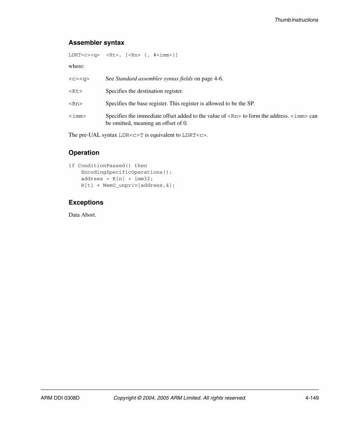
Thumb Instructions
Assembler syntax
LDRT<c><q> <Rt>, [<Rn> {, #<imm>}]
where:
<c><q> See Standard assembler syntax fields on page 4-6.
<Rt> Specifies the destination register.
<Rn> Specifies the base register. This register is allowed to be the SP.
<imm> Specifies the immediate offset added to the value of <Rn> to form the address. <imm> can be omitted, meaning an offset of 0.
The pre-UAL syntax LDR<c>T is equivalent to LDRT<c>.
Operation
if ConditionPassed() then EncodingSpecificOperations(); address = R[n] + imm32; R[t] = MemU_unpriv[address,4];
Exceptions
Data Abort.
ARM DDI 0308D Copyright © 2004, 2005 ARM Limited. All rights reserved. 4-149
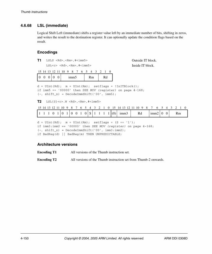
Thumb Instructions
4.6.68 LSL (immediate)
Logical Shift Left (immediate) shifts a register value left by an immediate number of bits, shifting in zeros, and writes the result to the destination register. It can optionally update the condition flags based on the result.
Encodings
d = UInt(Rd); m = UInt(Rm); setflags = !InITBlock();if imm5 == '00000' then SEE MOV (register) on page 4-168;(-, shift_n) = DecodeImmShift('00', imm5);
d = UInt(Rd); m = UInt(Rm); setflags = (S == '1');if imm3:imm2 == '00000' then SEE MOV (register) on page 4-168;(-, shift_n) = DecodeImmShift('00', imm3:imm2);if BadReg(d) || BadReg(m) THEN UNPREDICTABLE;
Architecture versions
Encoding T1 All versions of the Thumb instruction set.
Encoding T2 All versions of the Thumb instruction set from Thumb-2 onwards.
T1 LSLS <Rd>,<Rm>,#<imm5> Outside IT block.LSL<c> <Rd>,<Rm>,#<imm5> Inside IT block.
15 14 13 12 11 10 9 8 7 6 5 4 3 2 1 0
0 0 0 0 0 imm5 Rm Rd
T2 LSL{S}<c>.W <Rd>,<Rm>,#<imm5>
15 14 13 12 11 10 9 8 7 6 5 4 3 2 1 0 15 14 13 12 11 10 9 8 7 6 5 4 3 2 1 0
1 1 1 0 1 0 1 0 0 1 0 S 1 1 1 1 (0) imm3 Rd imm2 0 0 Rm
4-150 Copyright © 2004, 2005 ARM Limited. All rights reserved. ARM DDI 0308D

Thumb Instructions
Assembler syntax
LSL{S}<c><q> <Rd>, <Rm>, #<imm5>
where:
S If present, specifies that the instruction updates the flags. Otherwise, the instruction does not update the flags.
<c><q> See Standard assembler syntax fields on page 4-6.
<Rd> Specifies the destination register.
<Rm> Specifies the register that contains the first operand.
<imm5> Specifies the shift amount, in the range 0 to 31. See Constant shifts applied to a register on page 4-10.
Operation
if ConditionPassed() then EncodingSpecificOperations(); (result, carry) = Shift_C(R[m], SRType_LSL, shift_n, APSR.C); R[d] = result; if setflags then APSR.N = result<31>; APSR.Z = IsZeroBit(result); APSR.C = carry; // APSR.V unchanged
Exceptions
None.
ARM DDI 0308D Copyright © 2004, 2005 ARM Limited. All rights reserved. 4-151

Thumb Instructions
4.6.69 LSL (register)
Logical Shift Left (register) shifts a register value left by a variable number of bits, shifting in zeros, and writes the result to the destination register. The variable number of bits is read from the bottom byte of a register. It can optionally update the condition flags based on the result.
Encodings
d = UInt(Rdn); n = UInt(Rdn); m = UInt(Rm); setflags = !InITBlock();
d = UInt(Rd); n = UInt(Rn); m = UInt(Rm); setflags = (S == '1');if BadReg(d) || BadReg(n) || BadReg(m) then UNPREDICTABLE;
Architecture versions
Encoding T1 All versions of the Thumb instruction set
Encoding T2 All versions of the Thumb instruction set from Thumb-2 onwards.
T1 LSLS <Rdn>,<Rm> Outside IT block.LSL<c> <Rdn>,<Rm> Inside IT block.
15 14 13 12 11 10 9 8 7 6 5 4 3 2 1 0
0 1 0 0 0 0 0 0 1 0 Rm Rdn
T2 LSL{S}<c>.W <Rd>,<Rn>,<Rm>
15 14 13 12 11 10 9 8 7 6 5 4 3 2 1 0 15 14 13 12 11 10 9 8 7 6 5 4 3 2 1 0
1 1 1 1 1 0 1 0 0 0 0 S Rn 1 1 1 1 Rd 0 0 0 0 Rm
4-152 Copyright © 2004, 2005 ARM Limited. All rights reserved. ARM DDI 0308D
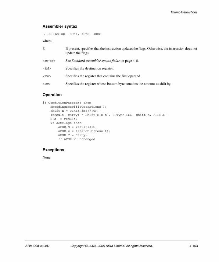
Thumb Instructions
Assembler syntax
LSL{S}<c><q> <Rd>, <Rn>, <Rm>
where:
S If present, specifies that the instruction updates the flags. Otherwise, the instruction does not update the flags.
<c><q> See Standard assembler syntax fields on page 4-6.
<Rd> Specifies the destination register.
<Rn> Specifies the register that contains the first operand.
<Rm> Specifies the register whose bottom byte contains the amount to shift by.
Operation
if ConditionPassed() then EncodingSpecificOperations(); shift_n = UInt(R[m]<7:0>); (result, carry) = Shift_C(R[n], SRType_LSL, shift_n, APSR.C); R[d] = result; if setflags then APSR.N = result<31>; APSR.Z = IsZeroBit(result); APSR.C = carry; // APSR.V unchanged
Exceptions
None.
ARM DDI 0308D Copyright © 2004, 2005 ARM Limited. All rights reserved. 4-153
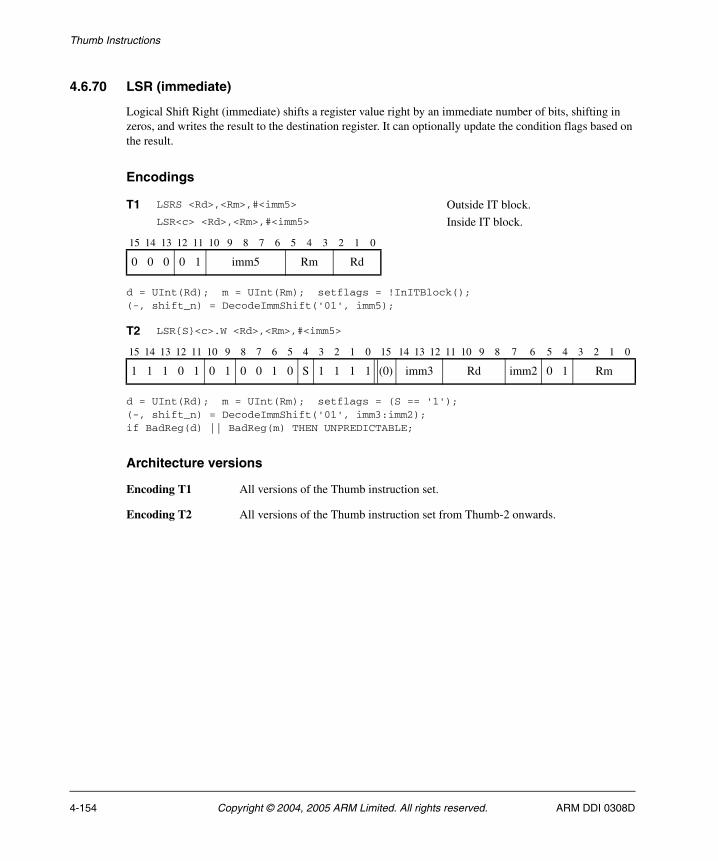
Thumb Instructions
4.6.70 LSR (immediate)
Logical Shift Right (immediate) shifts a register value right by an immediate number of bits, shifting in zeros, and writes the result to the destination register. It can optionally update the condition flags based on the result.
Encodings
d = UInt(Rd); m = UInt(Rm); setflags = !InITBlock();(-, shift_n) = DecodeImmShift('01', imm5);
d = UInt(Rd); m = UInt(Rm); setflags = (S == '1');(-, shift_n) = DecodeImmShift('01', imm3:imm2);if BadReg(d) || BadReg(m) THEN UNPREDICTABLE;
Architecture versions
Encoding T1 All versions of the Thumb instruction set.
Encoding T2 All versions of the Thumb instruction set from Thumb-2 onwards.
T1 LSRS <Rd>,<Rm>,#<imm5> Outside IT block.LSR<c> <Rd>,<Rm>,#<imm5> Inside IT block.
15 14 13 12 11 10 9 8 7 6 5 4 3 2 1 0
0 0 0 0 1 imm5 Rm Rd
T2 LSR{S}<c>.W <Rd>,<Rm>,#<imm5>
15 14 13 12 11 10 9 8 7 6 5 4 3 2 1 0 15 14 13 12 11 10 9 8 7 6 5 4 3 2 1 0
1 1 1 0 1 0 1 0 0 1 0 S 1 1 1 1 (0) imm3 Rd imm2 0 1 Rm
4-154 Copyright © 2004, 2005 ARM Limited. All rights reserved. ARM DDI 0308D

Thumb Instructions
Assembler syntax
LSR{S}<c><q> <Rd>, <Rm>, #<imm5>
where:
S If present, specifies that the instruction updates the flags. Otherwise, the instruction does not update the flags.
<c><q> See Standard assembler syntax fields on page 4-6.
<Rd> Specifies the destination register.
<Rm> Specifies the register that contains the first operand.
<imm5> Specifies the shift amount, in the range 1 to 32. See Constant shifts applied to a register on page 4-10.
Operation
if ConditionPassed() then EncodingSpecificOperations(); (result, carry) = Shift_C(R[m], SRType_LSR, shift_n, APSR.C); R[d] = result; if setflags then APSR.N = result<31>; APSR.Z = IsZeroBit(result); APSR.C = carry; // APSR.V unchanged
Exceptions
None.
ARM DDI 0308D Copyright © 2004, 2005 ARM Limited. All rights reserved. 4-155
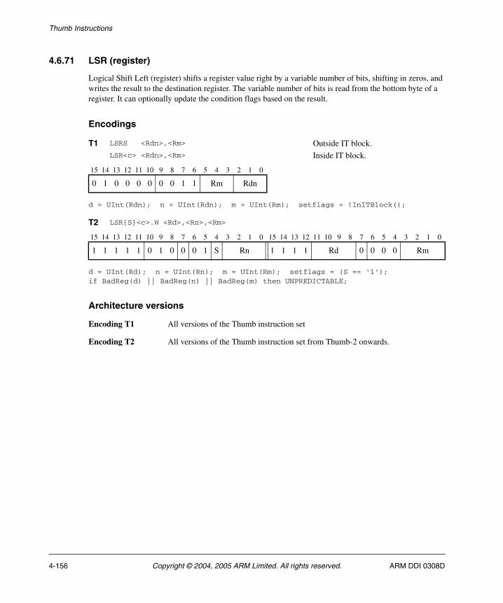
Thumb Instructions
4.6.71 LSR (register)
Logical Shift Left (register) shifts a register value right by a variable number of bits, shifting in zeros, and writes the result to the destination register. The variable number of bits is read from the bottom byte of a register. It can optionally update the condition flags based on the result.
Encodings
d = UInt(Rdn); n = UInt(Rdn); m = UInt(Rm); setflags = !InITBlock();
d = UInt(Rd); n = UInt(Rn); m = UInt(Rm); setflags = (S == '1');if BadReg(d) || BadReg(n) || BadReg(m) then UNPREDICTABLE;
Architecture versions
Encoding T1 All versions of the Thumb instruction set
Encoding T2 All versions of the Thumb instruction set from Thumb-2 onwards.
T1 LSRS <Rdn>,<Rm> Outside IT block.LSR<c> <Rdn>,<Rm> Inside IT block.
15 14 13 12 11 10 9 8 7 6 5 4 3 2 1 0
0 1 0 0 0 0 0 0 1 1 Rm Rdn
T2 LSR{S}<c>.W <Rd>,<Rn>,<Rm>
15 14 13 12 11 10 9 8 7 6 5 4 3 2 1 0 15 14 13 12 11 10 9 8 7 6 5 4 3 2 1 0
1 1 1 1 1 0 1 0 0 0 1 S Rn 1 1 1 1 Rd 0 0 0 0 Rm
4-156 Copyright © 2004, 2005 ARM Limited. All rights reserved. ARM DDI 0308D

Thumb Instructions
Assembler syntax
LSR{S}<c><q> <Rd>, <Rn>, <Rm>
where:
S If present, specifies that the instruction updates the flags. Otherwise, the instruction does not update the flags.
<c><q> See Standard assembler syntax fields on page 4-6.
<Rd> Specifies the destination register.
<Rn> Specifies the register that contains the first operand.
<Rm> Specifies the register whose bottom byte contains the amount to shift by.
Operation
if ConditionPassed() then EncodingSpecificOperations(); shift_n = UInt(R[m]<7:0>); (result, carry) = Shift_C(R[n], SRType_LSR, shift_n, APSR.C); R[d] = result; if setflags then APSR.N = result<31>; APSR.Z = IsZeroBit(result); APSR.C = carry; // APSR.V unchanged
Exceptions
None.
ARM DDI 0308D Copyright © 2004, 2005 ARM Limited. All rights reserved. 4-157
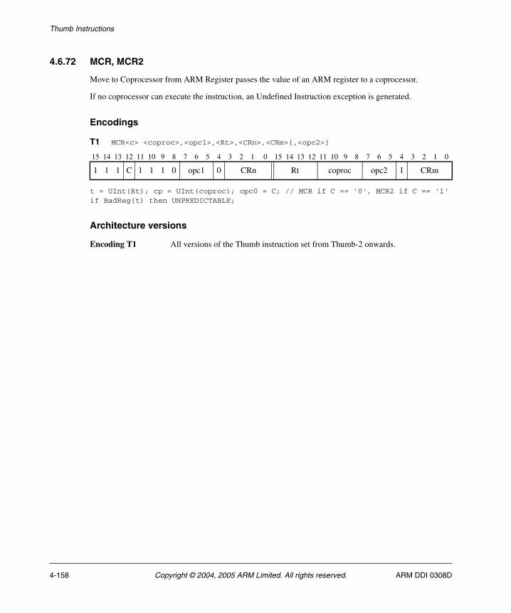
Thumb Instructions
4.6.72 MCR, MCR2
Move to Coprocessor from ARM Register passes the value of an ARM register to a coprocessor.
If no coprocessor can execute the instruction, an Undefined Instruction exception is generated.
Encodings
t = UInt(Rt); cp = UInt(coproc); opc0 = C; // MCR if C == '0', MCR2 if C == '1'if BadReg(t) then UNPREDICTABLE;
Architecture versions
Encoding T1 All versions of the Thumb instruction set from Thumb-2 onwards.
T1 MCR<c> <coproc>,<opc1>,<Rt>,<CRn>,<CRm>{,<opc2>}
15 14 13 12 11 10 9 8 7 6 5 4 3 2 1 0 15 14 13 12 11 10 9 8 7 6 5 4 3 2 1 0
1 1 1 C 1 1 1 0 opc1 0 CRn Rt coproc opc2 1 CRm
4-158 Copyright © 2004, 2005 ARM Limited. All rights reserved. ARM DDI 0308D
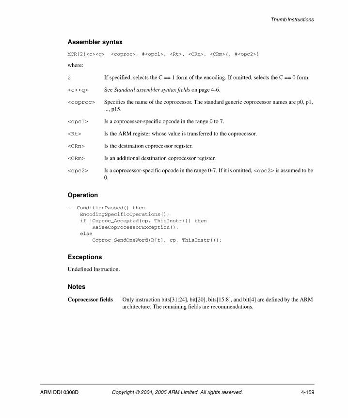
Thumb Instructions
Assembler syntax
MCR{2}<c><q> <coproc>, #<opc1>, <Rt>, <CRn>, <CRm>{, #<opc2>}
where:
2 If specified, selects the C == 1 form of the encoding. If omitted, selects the C == 0 form.
<c><q> See Standard assembler syntax fields on page 4-6.
<coproc> Specifies the name of the coprocessor. The standard generic coprocessor names are p0, p1, ..., p15.
<opc1> Is a coprocessor-specific opcode in the range 0 to 7.
<Rt> Is the ARM register whose value is transferred to the coprocessor.
<CRn> Is the destination coprocessor register.
<CRm> Is an additional destination coprocessor register.
<opc2> Is a coprocessor-specific opcode in the range 0-7. If it is omitted, <opc2> is assumed to be 0.
Operation
if ConditionPassed() then EncodingSpecificOperations(); if !Coproc_Accepted(cp, ThisInstr()) then RaiseCoprocessorException(); else Coproc_SendOneWord(R[t], cp, ThisInstr());
Exceptions
Undefined Instruction.
Notes
Coprocessor fields Only instruction bits[31:24], bit[20], bits[15:8], and bit[4] are defined by the ARM architecture. The remaining fields are recommendations.
ARM DDI 0308D Copyright © 2004, 2005 ARM Limited. All rights reserved. 4-159
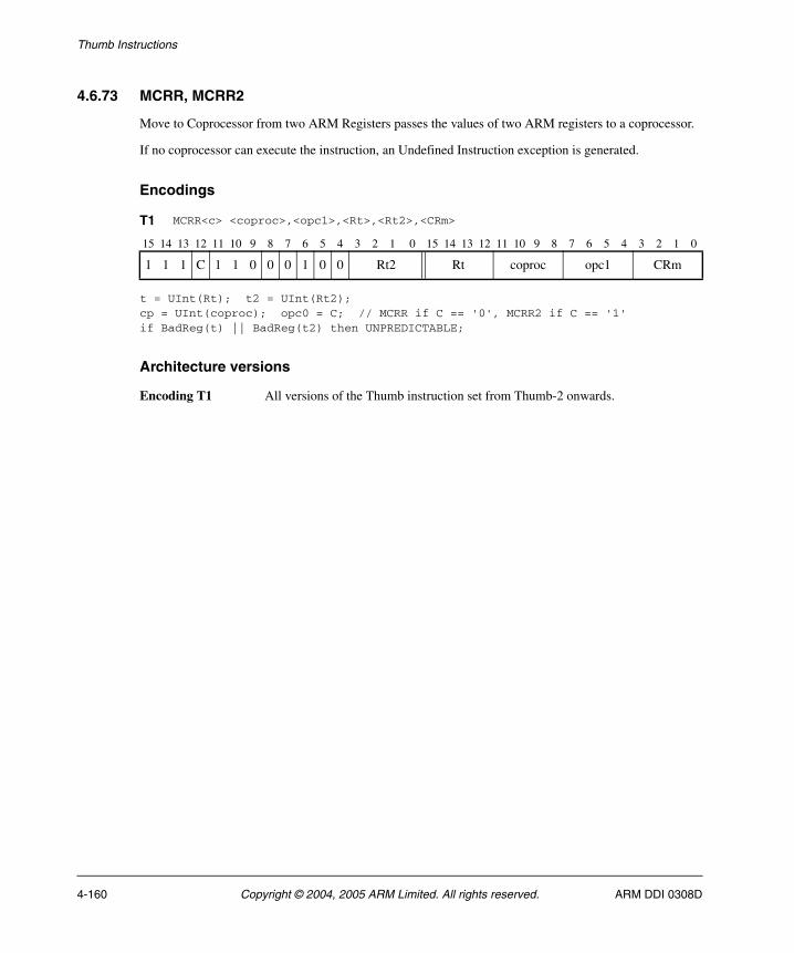
Thumb Instructions
4.6.73 MCRR, MCRR2
Move to Coprocessor from two ARM Registers passes the values of two ARM registers to a coprocessor.
If no coprocessor can execute the instruction, an Undefined Instruction exception is generated.
Encodings
t = UInt(Rt); t2 = UInt(Rt2);cp = UInt(coproc); opc0 = C; // MCRR if C == '0', MCRR2 if C == '1'if BadReg(t) || BadReg(t2) then UNPREDICTABLE;
Architecture versions
Encoding T1 All versions of the Thumb instruction set from Thumb-2 onwards.
T1 MCRR<c> <coproc>,<opc1>,<Rt>,<Rt2>,<CRm>
15 14 13 12 11 10 9 8 7 6 5 4 3 2 1 0 15 14 13 12 11 10 9 8 7 6 5 4 3 2 1 0
1 1 1 C 1 1 0 0 0 1 0 0 Rt2 Rt coproc opc1 CRm
4-160 Copyright © 2004, 2005 ARM Limited. All rights reserved. ARM DDI 0308D
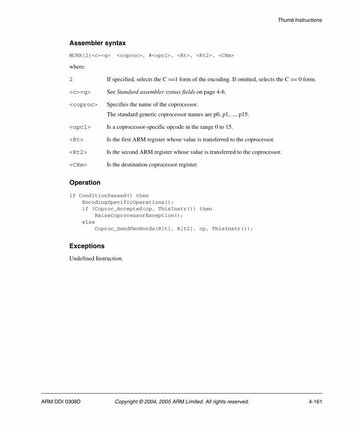
Thumb Instructions
Assembler syntax
MCRR{2}<c><q> <coproc>, #<opc1>, <Rt>, <Rt2>, <CRm>
where:
2 If specified, selects the C ==1 form of the encoding. If omitted, selects the C == 0 form.
<c><q> See Standard assembler syntax fields on page 4-6.
<coproc> Specifies the name of the coprocessor.
The standard generic coprocessor names are p0, p1, ..., p15.
<opc1> Is a coprocessor-specific opcode in the range 0 to 15.
<Rt> Is the first ARM register whose value is transferred to the coprocessor.
<Rt2> Is the second ARM register whose value is transferred to the coprocessor.
<CRm> Is the destination coprocessor register.
Operation
if ConditionPassed() then EncodingSpecificOperations(); if !Coproc_Accepted(cp, ThisInstr()) then RaiseCoprocessorException(); else Coproc_SendTwoWords(R[t], R[t2], cp, ThisInstr());
Exceptions
Undefined Instruction.
ARM DDI 0308D Copyright © 2004, 2005 ARM Limited. All rights reserved. 4-161

Thumb Instructions
4.6.74 MLA
Multiply Accumulate multiplies two register values, and adds a third register value. The least significant 32 bits of the result are written to the destination register. These 32 bits do not depend on whether signed or unsigned calculations are performed.
Encodings
d = UInt(Rd); n = UInt(Rn); m = UInt(Rm); a = UInt(Ra); if a == 15 then SEE MUL on page 4-181;if BadReg(d) || BadReg(n) || BadReg(m) || a == 13 then UNPREDICTABLE;
Architecture versions
Encoding T1 All versions of the Thumb instruction set from Thumb-2 onwards.
T1 MLA<c> <Rd>,<Rn>,<Rm>,<Ra>
15 14 13 12 11 10 9 8 7 6 5 4 3 2 1 0 15 14 13 12 11 10 9 8 7 6 5 4 3 2 1 0
1 1 1 1 1 0 1 1 0 0 0 0 Rn Ra Rd 0 0 0 0 Rm
4-162 Copyright © 2004, 2005 ARM Limited. All rights reserved. ARM DDI 0308D

Thumb Instructions
Assembler syntax
MLA<c><q> <Rd>, <Rn>, <Rm>, <Ra>
where:
<c><q> See Standard assembler syntax fields on page 4-6.
<Rd> Specifies the destination register.
<Rn> Specifies the register that contains the first operand.
<Rm> Specifies the register that contains the second operand.
<Ra> Specifies the register containing the accumulate value.
Operation
if ConditionPassed() then EncodingSpecificOperations(); operand1 = SInt(R[n]); // or UInt(R[n]) without functionality change operand2 = SInt(R[m]); // or UInt(R[m]) without functionality change addend = SInt(R[a]); // or UInt(R[a]) without functionality change result = operand1 * operand2 + addend; R[d] = result<31:0>;
Exceptions
None.
ARM DDI 0308D Copyright © 2004, 2005 ARM Limited. All rights reserved. 4-163

Thumb Instructions
4.6.75 MLS
Multiply and Subtract multiplies two register values, and subtracts the least significant 32 bits of the result from a third register value. These 32 bits do not depend on whether signed or unsigned calculations are performed. The result is written to the destination register.
Encodings
d = UInt(Rd); n = UInt(Rn); m = UInt(Rm); a = UInt(Ra); if BadReg(d) || BadReg(n) || BadReg(m) || BadReg(a) then UNPREDICTABLE;
Architecture versions
Encoding T1 All versions of the Thumb instruction set from Thumb-2 onwards.
T1 MLS<c> <Rd>,<Rn>,<Rm>,<Ra>
15 14 13 12 11 10 9 8 7 6 5 4 3 2 1 0 15 14 13 12 11 10 9 8 7 6 5 4 3 2 1 0
1 1 1 1 1 0 1 1 0 0 0 0 Rn Ra Rd 0 0 0 1 Rm
4-164 Copyright © 2004, 2005 ARM Limited. All rights reserved. ARM DDI 0308D
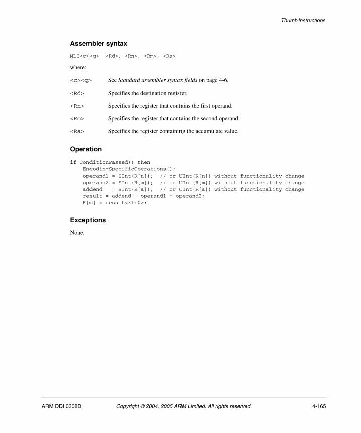
Thumb Instructions
Assembler syntax
MLS<c><q> <Rd>, <Rn>, <Rm>, <Ra>
where:
<c><q> See Standard assembler syntax fields on page 4-6.
<Rd> Specifies the destination register.
<Rn> Specifies the register that contains the first operand.
<Rm> Specifies the register that contains the second operand.
<Ra> Specifies the register containing the accumulate value.
Operation
if ConditionPassed() then EncodingSpecificOperations(); operand1 = SInt(R[n]); // or UInt(R[n]) without functionality change operand2 = SInt(R[m]); // or UInt(R[m]) without functionality change addend = SInt(R[a]); // or UInt(R[a]) without functionality change result = addend - operand1 * operand2; R[d] = result<31:0>;
Exceptions
None.
ARM DDI 0308D Copyright © 2004, 2005 ARM Limited. All rights reserved. 4-165
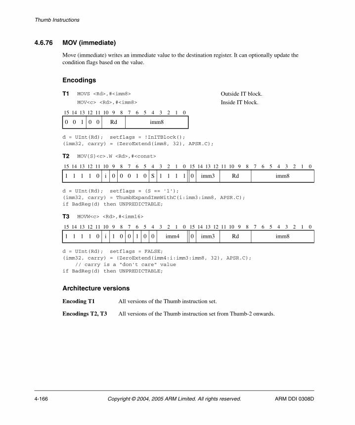
Thumb Instructions
4.6.76 MOV (immediate)
Move (immediate) writes an immediate value to the destination register. It can optionally update the condition flags based on the value.
Encodings
d = UInt(Rd); setflags = !InITBlock();(imm32, carry) = (ZeroExtend(imm8, 32), APSR.C);
d = UInt(Rd); setflags = (S == '1');(imm32, carry) = ThumbExpandImmWithC(i:imm3:imm8, APSR.C);if BadReg(d) then UNPREDICTABLE;
d = UInt(Rd); setflags = FALSE;(imm32, carry) = (ZeroExtend(imm4:i:imm3:imm8, 32), APSR.C); // carry is a "don't care" valueif BadReg(d) then UNPREDICTABLE;
Architecture versions
Encoding T1 All versions of the Thumb instruction set.
Encodings T2, T3 All versions of the Thumb instruction set from Thumb-2 onwards.
T1 MOVS <Rd>,#<imm8> Outside IT block.MOV<c> <Rd>,#<imm8> Inside IT block.
15 14 13 12 11 10 9 8 7 6 5 4 3 2 1 0
0 0 1 0 0 Rd imm8
T2 MOV{S}<c>.W <Rd>,#<const>
15 14 13 12 11 10 9 8 7 6 5 4 3 2 1 0 15 14 13 12 11 10 9 8 7 6 5 4 3 2 1 0
1 1 1 1 0 i 0 0 0 1 0 S 1 1 1 1 0 imm3 Rd imm8
T3 MOVW<c> <Rd>,#<imm16>
15 14 13 12 11 10 9 8 7 6 5 4 3 2 1 0 15 14 13 12 11 10 9 8 7 6 5 4 3 2 1 0
1 1 1 1 0 i 1 0 0 1 0 0 imm4 0 imm3 Rd imm8
4-166 Copyright © 2004, 2005 ARM Limited. All rights reserved. ARM DDI 0308D
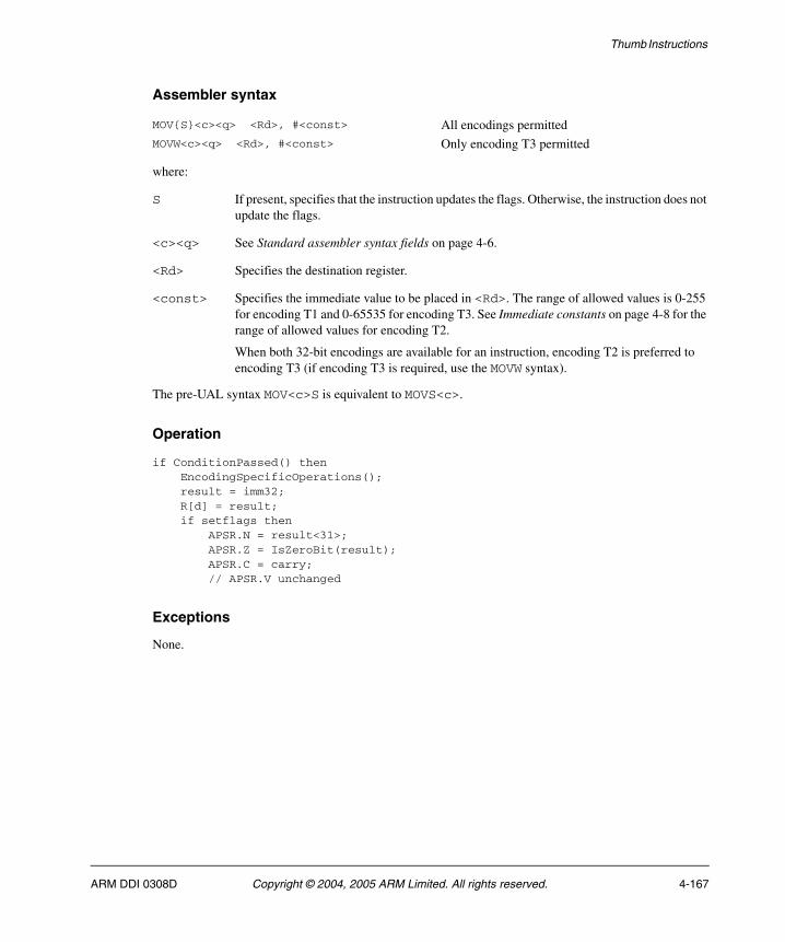
Thumb Instructions
Assembler syntax
where:
S If present, specifies that the instruction updates the flags. Otherwise, the instruction does not update the flags.
<c><q> See Standard assembler syntax fields on page 4-6.
<Rd> Specifies the destination register.
<const> Specifies the immediate value to be placed in <Rd>. The range of allowed values is 0-255 for encoding T1 and 0-65535 for encoding T3. See Immediate constants on page 4-8 for the range of allowed values for encoding T2.
When both 32-bit encodings are available for an instruction, encoding T2 is preferred to encoding T3 (if encoding T3 is required, use the MOVW syntax).
The pre-UAL syntax MOV<c>S is equivalent to MOVS<c>.
Operation
if ConditionPassed() then EncodingSpecificOperations(); result = imm32; R[d] = result; if setflags then APSR.N = result<31>; APSR.Z = IsZeroBit(result); APSR.C = carry; // APSR.V unchanged
Exceptions
None.
MOV{S}<c><q> <Rd>, #<const> All encodings permittedMOVW<c><q> <Rd>, #<const> Only encoding T3 permitted
ARM DDI 0308D Copyright © 2004, 2005 ARM Limited. All rights reserved. 4-167
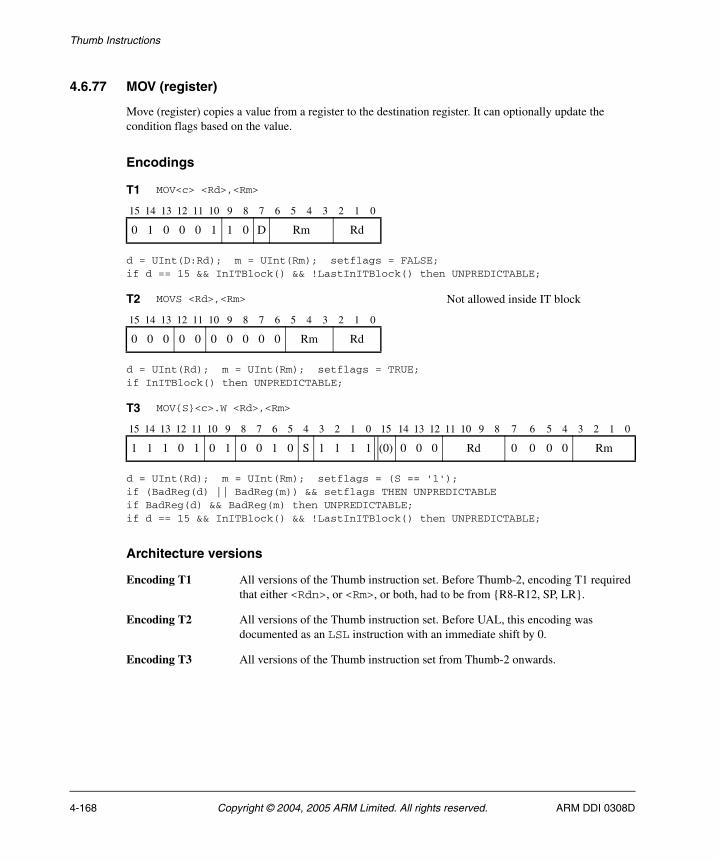
Thumb Instructions
4.6.77 MOV (register)
Move (register) copies a value from a register to the destination register. It can optionally update the condition flags based on the value.
Encodings
d = UInt(D:Rd); m = UInt(Rm); setflags = FALSE;if d == 15 && InITBlock() && !LastInITBlock() then UNPREDICTABLE;
d = UInt(Rd); m = UInt(Rm); setflags = TRUE;if InITBlock() then UNPREDICTABLE;
d = UInt(Rd); m = UInt(Rm); setflags = (S == '1');if (BadReg(d) || BadReg(m)) && setflags THEN UNPREDICTABLEif BadReg(d) && BadReg(m) then UNPREDICTABLE;if d == 15 && InITBlock() && !LastInITBlock() then UNPREDICTABLE;
Architecture versions
Encoding T1 All versions of the Thumb instruction set. Before Thumb-2, encoding T1 required that either <Rdn>, or <Rm>, or both, had to be from {R8-R12, SP, LR}.
Encoding T2 All versions of the Thumb instruction set. Before UAL, this encoding was documented as an LSL instruction with an immediate shift by 0.
Encoding T3 All versions of the Thumb instruction set from Thumb-2 onwards.
T1 MOV<c> <Rd>,<Rm>
15 14 13 12 11 10 9 8 7 6 5 4 3 2 1 0
0 1 0 0 0 1 1 0 D Rm Rd
T2 MOVS <Rd>,<Rm> Not allowed inside IT block
15 14 13 12 11 10 9 8 7 6 5 4 3 2 1 0
0 0 0 0 0 0 0 0 0 0 Rm Rd
T3 MOV{S}<c>.W <Rd>,<Rm>
15 14 13 12 11 10 9 8 7 6 5 4 3 2 1 0 15 14 13 12 11 10 9 8 7 6 5 4 3 2 1 0
1 1 1 0 1 0 1 0 0 1 0 S 1 1 1 1 (0) 0 0 0 Rd 0 0 0 0 Rm
4-168 Copyright © 2004, 2005 ARM Limited. All rights reserved. ARM DDI 0308D
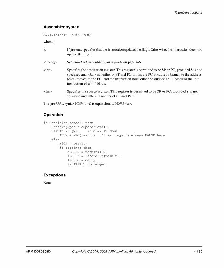
Thumb Instructions
Assembler syntax
MOV{S}<c><q> <Rd>, <Rm>
where:
S If present, specifies that the instruction updates the flags. Otherwise, the instruction does not update the flags.
<c><q> See Standard assembler syntax fields on page 4-6.
<Rd> Specifies the destination register. This register is permitted to be SP or PC, provided S is not specified and <Rm> is neither of SP and PC. If it is the PC, it causes a branch to the address (data) moved to the PC, and the instruction must either be outside an IT block or the last instruction of an IT block.
<Rm> Specifies the source register. This register is permitted to be SP or PC, provided S is not specified and <Rd> is neither of SP and PC.
The pre-UAL syntax MOV<c>S is equivalent to MOVS<c>.
Operation
if ConditionPassed() then EncodingSpecificOperations(); result = R[m]; if d == 15 then ALUWritePC(result); // setflags is always FALSE here else R[d] = result; if setflags then APSR.N = result<31>; APSR.Z = IsZeroBit(result); APSR.C = carry; // APSR.V unchanged
Exceptions
None.
ARM DDI 0308D Copyright © 2004, 2005 ARM Limited. All rights reserved. 4-169
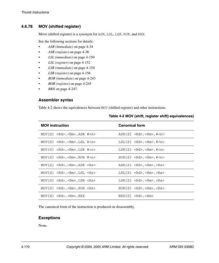
Thumb Instructions
4.6.78 MOV (shifted register)
Move (shifted register) is a synonym for ASR, LSL, LSR, ROR, and RRX.
See the following sections for details:
• ASR (immediate) on page 4-34
• ASR (register) on page 4-36
• LSL (immediate) on page 4-150
• LSL (register) on page 4-152
• LSR (immediate) on page 4-154
• LSR (register) on page 4-156
• ROR (immediate) on page 4-243
• ROR (register) on page 4-245
• RRX on page 4-247.
Assembler syntax
Table 4-2 shows the equivalences between MOV (shifted register) and other instructions.
The canonical form of the instruction is produced on disassembly.
Exceptions
None.
Table 4-2 MOV (shift, register shift) equivalences)
MOV instruction Canonical form
MOV{S} <Rd>,<Rm>,ASR #<n> ASR{S} <Rd>,<Rm>,#<n>
MOV{S} <Rd>,<Rm>,LSL #<n> LSL{S} <Rd>,<Rm>,#<n>
MOV{S} <Rd>,<Rm>,LSR #<n> LSR{S} <Rd>,<Rm>,#<n>
MOV{S} <Rd>,<Rm>,ROR #<n> ROR{S} <Rd>,<Rm>,#<n>
MOV{S} <Rd>,<Rm>,ASR <Rs> ASR{S} <Rd>,<Rm>,<Rs>
MOV{S} <Rd>,<Rm>,LSL <Rs> LSL{S} <Rd>,<Rm>,<Rs>
MOV{S} <Rd>,<Rm>,LSR <Rs> LSR{S} <Rd>,<Rm>,<Rs>
MOV{S} <Rd>,<Rm>,ROR <Rs> ROR{S} <Rd>,<Rm>,<Rs>
MOV{S} <Rd>,<Rm>,RRX RRX{S} <Rd>,<Rm>
4-170 Copyright © 2004, 2005 ARM Limited. All rights reserved. ARM DDI 0308D
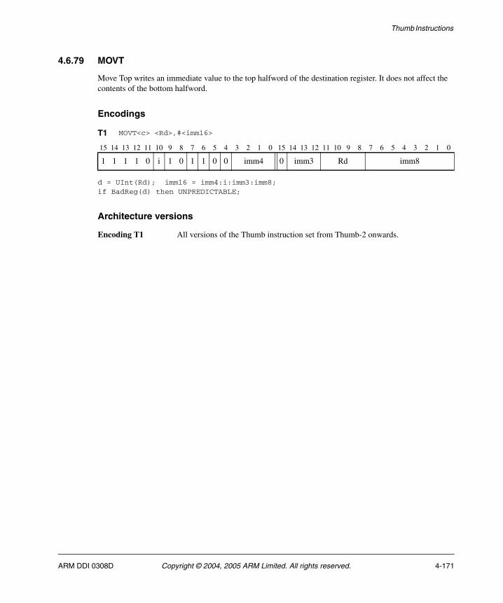
Thumb Instructions
4.6.79 MOVT
Move Top writes an immediate value to the top halfword of the destination register. It does not affect the contents of the bottom halfword.
Encodings
d = UInt(Rd); imm16 = imm4:i:imm3:imm8; if BadReg(d) then UNPREDICTABLE;
Architecture versions
Encoding T1 All versions of the Thumb instruction set from Thumb-2 onwards.
T1 MOVT<c> <Rd>,#<imm16>
15 14 13 12 11 10 9 8 7 6 5 4 3 2 1 0 15 14 13 12 11 10 9 8 7 6 5 4 3 2 1 0
1 1 1 1 0 i 1 0 1 1 0 0 imm4 0 imm3 Rd imm8
ARM DDI 0308D Copyright © 2004, 2005 ARM Limited. All rights reserved. 4-171
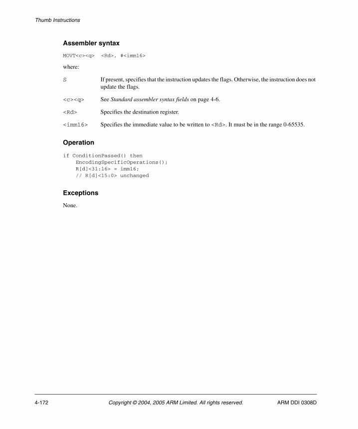
Thumb Instructions
Assembler syntax
MOVT<c><q> <Rd>, #<imm16>
where:
S If present, specifies that the instruction updates the flags. Otherwise, the instruction does not update the flags.
<c><q> See Standard assembler syntax fields on page 4-6.
<Rd> Specifies the destination register.
<imm16> Specifies the immediate value to be written to <Rd>. It must be in the range 0-65535.
Operation
if ConditionPassed() then EncodingSpecificOperations(); R[d]<31:16> = imm16; // R[d]<15:0> unchanged
Exceptions
None.
4-172 Copyright © 2004, 2005 ARM Limited. All rights reserved. ARM DDI 0308D
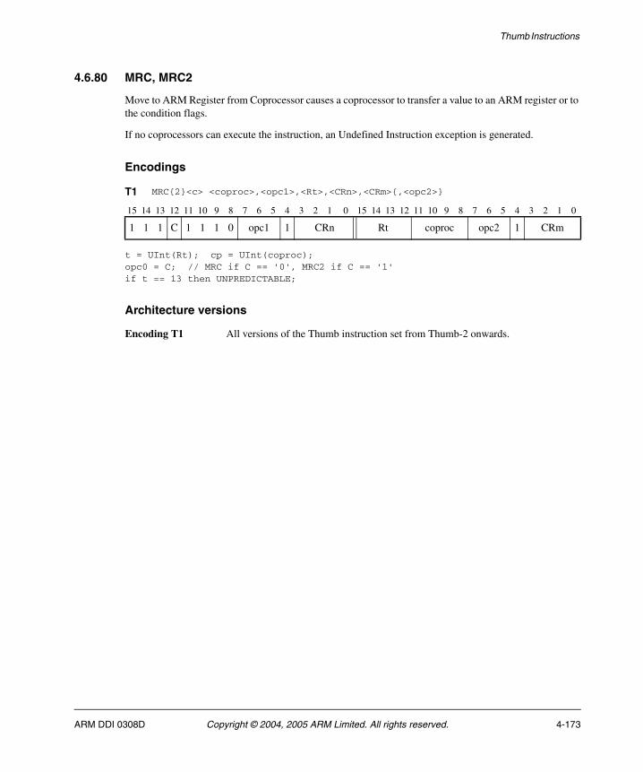
Thumb Instructions
4.6.80 MRC, MRC2
Move to ARM Register from Coprocessor causes a coprocessor to transfer a value to an ARM register or to the condition flags.
If no coprocessors can execute the instruction, an Undefined Instruction exception is generated.
Encodings
t = UInt(Rt); cp = UInt(coproc);opc0 = C; // MRC if C == '0', MRC2 if C == '1'if t == 13 then UNPREDICTABLE;
Architecture versions
Encoding T1 All versions of the Thumb instruction set from Thumb-2 onwards.
T1 MRC{2}<c> <coproc>,<opc1>,<Rt>,<CRn>,<CRm>{,<opc2>}
15 14 13 12 11 10 9 8 7 6 5 4 3 2 1 0 15 14 13 12 11 10 9 8 7 6 5 4 3 2 1 0
1 1 1 C 1 1 1 0 opc1 1 CRn Rt coproc opc2 1 CRm
ARM DDI 0308D Copyright © 2004, 2005 ARM Limited. All rights reserved. 4-173
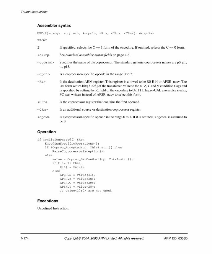
Thumb Instructions
Assembler syntax
MRC{2}<c><q> <coproc>, #<opc1>, <Rt>, <CRn>, <CRm>{, #<opc2>}
where:
2 If specified, selects the C == 1 form of the encoding. If omitted, selects the C == 0 form.
<c><q> See Standard assembler syntax fields on page 4-6.
<coproc> Specifies the name of the coprocessor. The standard generic coprocessor names are p0, p1, ..., p15.
<opc1> Is a coprocessor-specific opcode in the range 0 to 7.
<Rt> Is the destination ARM register. This register is allowed to be R0-R14 or APSR_nzcv. The last form writes bits[31:28] of the transferred value to the N, Z, C and V condition flags and is specified by setting the Rt field of the encoding to 0b1111. In pre-UAL assembler syntax, PC was written instead of APSR_nzcv to select this form.
<CRn> Is the coprocessor register that contains the first operand.
<CRm> Is an additional source or destination coprocessor register.
<opc2> Is a coprocessor-specific opcode in the range 0 to 7. If it is omitted, <opc2> is assumed to be 0.
Operation
if ConditionPassed() then EncodingSpecificOperations(); if !Coproc_Accepted(cp, ThisInstr()) then RaiseCoprocessorException(); else value = Coproc_GetOneWord(cp, ThisInstr()); if t != 15 then R[t] = value; else APSR.N = value<31>; APSR.Z = value<30>; APSR.C = value<29>; APSR.V = value<28>; // value<27:0> are not used.
Exceptions
Undefined Instruction.
4-174 Copyright © 2004, 2005 ARM Limited. All rights reserved. ARM DDI 0308D
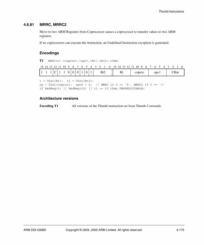
Thumb Instructions
4.6.81 MRRC, MRRC2
Move to two ARM Registers from Coprocessor causes a coprocessor to transfer values to two ARM registers.
If no coprocessors can execute the instruction, an Undefined Instruction exception is generated.
Encodings
t = UInt(Rt); t2 = UInt(Rt2);cp = UInt(coproc); opc0 = C; // MRRC if C == '0', MRRC2 if C == '1'if BadReg(t) || BadReg(t2) || t1 == t2 then UNPREDICTABLE;
Architecture versions
Encoding T1 All versions of the Thumb instruction set from Thumb-2 onwards.
T1 MRRC<c> <coproc>,<opc>,<Rt>,<Rt2>,<CRm>
15 14 13 12 11 10 9 8 7 6 5 4 3 2 1 0 15 14 13 12 11 10 9 8 7 6 5 4 3 2 1 0
1 1 1 C 1 1 0 0 0 1 0 1 Rt2 Rt coproc opc1 CRm
ARM DDI 0308D Copyright © 2004, 2005 ARM Limited. All rights reserved. 4-175
Thumb Instructions
Assembler syntax
MRRC{2}<c><q> <coproc>, #<opc1>, <Rt>, <Rt2>, <CRm>
where:
2 If specified, selects the C == 1 form of the encoding. If omitted, selects the C == 0 form.
<c><q> See Standard assembler syntax fields on page 4-6.
<coproc> Specifies the name of the coprocessor. The standard generic coprocessor names are p0, p1, ..., p15.
<opc1> Is a coprocessor-specific opcode in the range 0 to 15.
<Rt> Is the first destination ARM register.
<Rt2> Is the second destination ARM register.
<CRm> Is the coprocessor register that supplies the data to be transferred.
Operation
if ConditionPassed() then EncodingSpecificOperations(); if !Coproc_Accepted(cp, ThisInstr()) then RaiseCoprocessorException(); else (R[t], R[t2]) = Coproc_GetTwoWords(cp, ThisInstr());
Exceptions
Undefined Instruction.
4-176 Copyright © 2004, 2005 ARM Limited. All rights reserved. ARM DDI 0308D
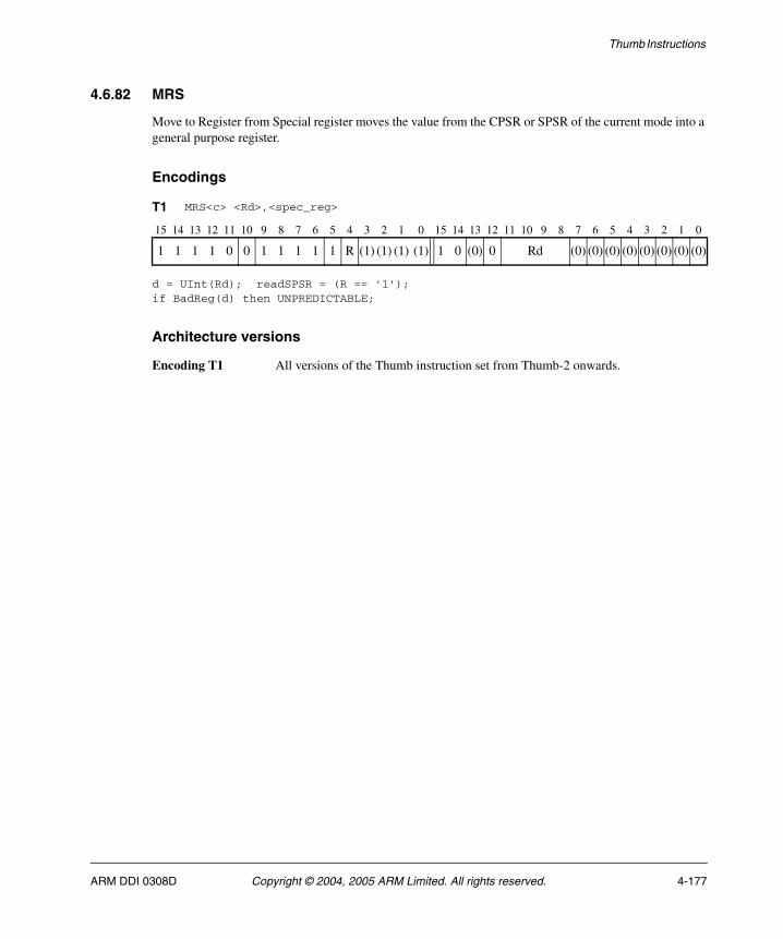
Thumb Instructions
4.6.82 MRS
Move to Register from Special register moves the value from the CPSR or SPSR of the current mode into a general purpose register.
Encodings
d = UInt(Rd); readSPSR = (R == '1');if BadReg(d) then UNPREDICTABLE;
Architecture versions
Encoding T1 All versions of the Thumb instruction set from Thumb-2 onwards.
T1 MRS<c> <Rd>,<spec_reg>
15 14 13 12 11 10 9 8 7 6 5 4 3 2 1 0 15 14 13 12 11 10 9 8 7 6 5 4 3 2 1 0
1 1 1 1 0 0 1 1 1 1 1 R (1) (1) (1) (1) 1 0 (0) 0 Rd (0) (0) (0) (0) (0) (0) (0) (0)
ARM DDI 0308D Copyright © 2004, 2005 ARM Limited. All rights reserved. 4-177
Thumb Instructions
Assembler syntax
MRS<c><q> <Rd>, <spec_reg>
where:
<c><q> See Standard assembler syntax fields on page 4-6.
<Rd> Specifies the destination register.
<spec_reg> Is APSR, CPSR, or SPSR. APSR is the recommended form when only the N, Z, C, V, Q, or GE[3:0] bits of the read value are going to be used (see The Application Program Status Register on page 2-2).
Operation
if ConditionPassed() then EncodingSpecificOperations(); if readSPSR then if CurrentModeHasSPSR() then R[d] = SPSR; else UNPREDICTABLE; else R[d] = CPSR;
Exceptions
None.
4-178 Copyright © 2004, 2005 ARM Limited. All rights reserved. ARM DDI 0308D
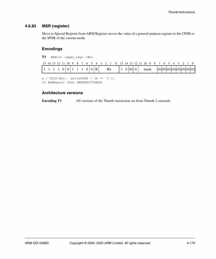
Thumb Instructions
4.6.83 MSR (register)
Move to Special Register from ARM Register moves the value of a general-purpose register to the CPSR or the SPSR of the current mode.
Encodings
n = UInt(Rn); writeSPSR = (R == '1');if BadReg(n) then UNPREDICTABLE;
Architecture versions
Encoding T1 All versions of the Thumb instruction set from Thumb-2 onwards.
T1 MSR<c> <spec_reg>,<Rn>
15 14 13 12 11 10 9 8 7 6 5 4 3 2 1 0 15 14 13 12 11 10 9 8 7 6 5 4 3 2 1 0
1 1 1 1 0 0 1 1 1 0 0 R Rn 1 0 (0) 0 mask (0) (0) (0) (0) (0) (0) (0) (0)
ARM DDI 0308D Copyright © 2004, 2005 ARM Limited. All rights reserved. 4-179

Thumb Instructions
Assembler syntax
MSR<c><q> <spec_reg>, <Rn>
where:
<c><q> See Standard assembler syntax fields on page 4-6.
<spec_reg> Is one of APSR_<bits>, CPSR_<fields>, or SPSR_<fields>. The APSR forms are recommended when only the N, Z, C, V, Q, and GE[3:0] bits are being written (see The Application Program Status Register on page 2-2).
<fields> Is a sequence of one or more of the following: c, x, s, f.
<Rn> Is the general-purpose register to be transferred to the special register.
<bits> Is one of nzcvq, g, or nzcvqg.
In the A and R profiles:
• APSR_nzcvq is the same as CPSR_f
• APSR_g is the same as CPSR_s
• APSR_nzcvqg is the same as CPSR_fs.
Operation
if ConditionPassed() then EncodingSpecificOperations(); if writeSPSR then if CurrentModeHasSPSR() then WriteSPSRUnderMask(R[n], mask); else UNPREDICTABLE; else WriteCPSRUnderMask(R[n], mask);
Exceptions
None.
4-180 Copyright © 2004, 2005 ARM Limited. All rights reserved. ARM DDI 0308D
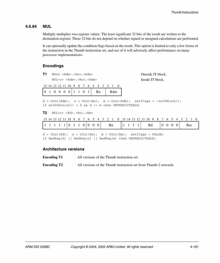
Thumb Instructions
4.6.84 MUL
Multiply multiplies two register values. The least significant 32 bits of the result are written to the destination register. These 32 bits do not depend on whether signed or unsigned calculations are performed.
It can optionally update the condition flags based on the result. This option is limited to only a few forms of the instruction in the Thumb instruction set, and use of it will adversely affect performance on many processor implementations.
Encodings
d = UInt(Rdm); n = UInt(Rn); m = UInt(Rdm); setflags = !InITBlock();if ArchVersion() < 6 && d == m then UNPREDICTABLE;
d = UInt(Rd); n = UInt(Rn); m = UInt(Rm); setflags = FALSE;if BadReg(d) || BadReg(n) || BadReg(m) then UNPREDICTABLE;
Architecture versions
Encoding T1 All versions of the Thumb instruction set.
Encoding T2 All versions of the Thumb instruction set from Thumb-2 onwards.
T1 MULS <Rdm>,<Rn>,<Rdm> Outside IT block.MUL<c> <Rdm>,<Rn>,<Rdm> Inside IT block.
15 14 13 12 11 10 9 8 7 6 5 4 3 2 1 0
0 1 0 0 0 0 1 1 0 1 Rn Rdm
T2 MUL<c> <Rd>,<Rn>,<Rm>
15 14 13 12 11 10 9 8 7 6 5 4 3 2 1 0 15 14 13 12 11 10 9 8 7 6 5 4 3 2 1 0
1 1 1 1 1 0 1 1 0 0 0 0 Rn 1 1 1 1 Rd 0 0 0 0 Rm
ARM DDI 0308D Copyright © 2004, 2005 ARM Limited. All rights reserved. 4-181
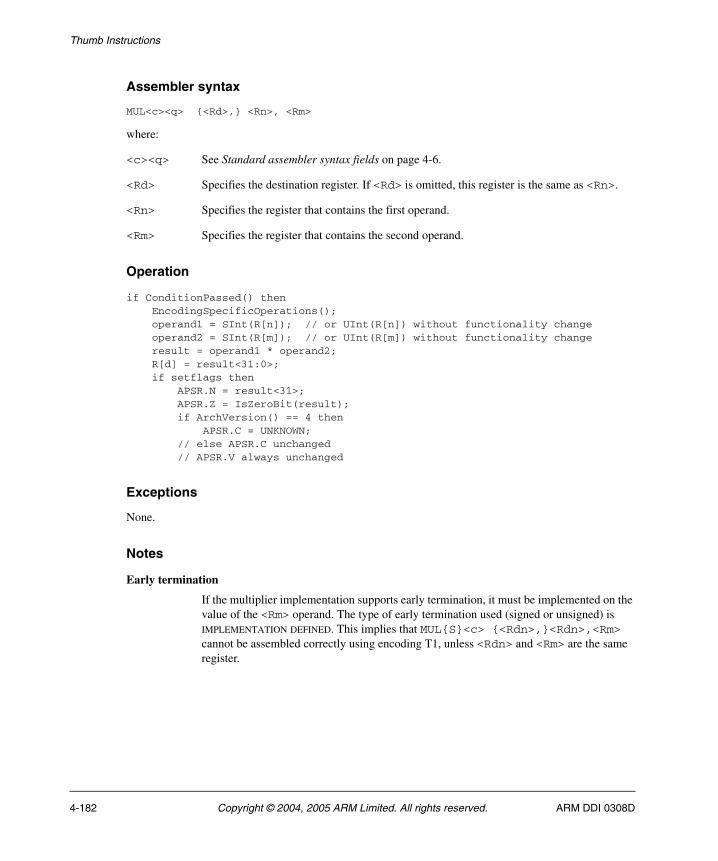
Thumb Instructions
Assembler syntax
MUL<c><q> {<Rd>,} <Rn>, <Rm>
where:
<c><q> See Standard assembler syntax fields on page 4-6.
<Rd> Specifies the destination register. If <Rd> is omitted, this register is the same as <Rn>.
<Rn> Specifies the register that contains the first operand.
<Rm> Specifies the register that contains the second operand.
Operation
if ConditionPassed() then EncodingSpecificOperations(); operand1 = SInt(R[n]); // or UInt(R[n]) without functionality change operand2 = SInt(R[m]); // or UInt(R[m]) without functionality change result = operand1 * operand2; R[d] = result<31:0>; if setflags then APSR.N = result<31>; APSR.Z = IsZeroBit(result); if ArchVersion() == 4 then APSR.C = UNKNOWN; // else APSR.C unchanged // APSR.V always unchanged
Exceptions
None.
Notes
Early termination
If the multiplier implementation supports early termination, it must be implemented on the value of the <Rm> operand. The type of early termination used (signed or unsigned) is IMPLEMENTATION DEFINED. This implies that MUL{S}<c> {<Rdn>,}<Rdn>,<Rm> cannot be assembled correctly using encoding T1, unless <Rdn> and <Rm> are the same register.
4-182 Copyright © 2004, 2005 ARM Limited. All rights reserved. ARM DDI 0308D
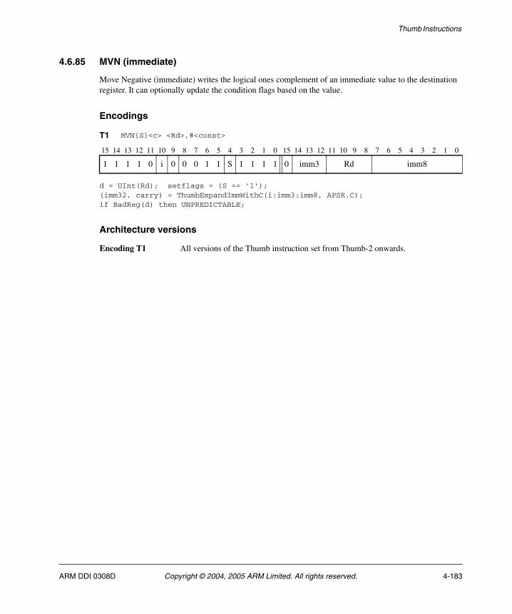
Thumb Instructions
4.6.85 MVN (immediate)
Move Negative (immediate) writes the logical ones complement of an immediate value to the destination register. It can optionally update the condition flags based on the value.
Encodings
d = UInt(Rd); setflags = (S == '1');(imm32, carry) = ThumbExpandImmWithC(i:imm3:imm8, APSR.C);if BadReg(d) then UNPREDICTABLE;
Architecture versions
Encoding T1 All versions of the Thumb instruction set from Thumb-2 onwards.
T1 MVN{S}<c> <Rd>,#<const>
15 14 13 12 11 10 9 8 7 6 5 4 3 2 1 0 15 14 13 12 11 10 9 8 7 6 5 4 3 2 1 0
1 1 1 1 0 i 0 0 0 1 1 S 1 1 1 1 0 imm3 Rd imm8
ARM DDI 0308D Copyright © 2004, 2005 ARM Limited. All rights reserved. 4-183
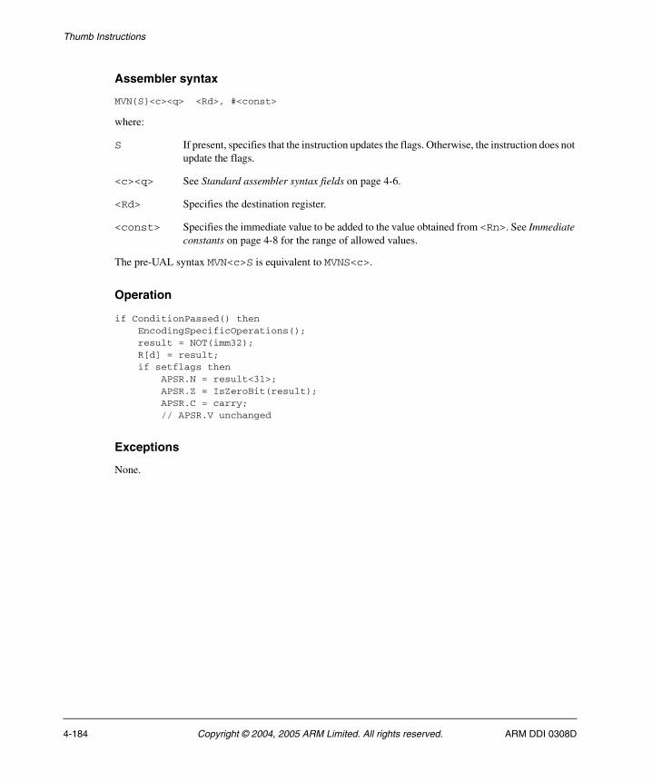
Thumb Instructions
Assembler syntax
MVN{S}<c><q> <Rd>, #<const>
where:
S If present, specifies that the instruction updates the flags. Otherwise, the instruction does not update the flags.
<c><q> See Standard assembler syntax fields on page 4-6.
<Rd> Specifies the destination register.
<const> Specifies the immediate value to be added to the value obtained from <Rn>. See Immediate constants on page 4-8 for the range of allowed values.
The pre-UAL syntax MVN<c>S is equivalent to MVNS<c>.
Operation
if ConditionPassed() then EncodingSpecificOperations(); result = NOT(imm32); R[d] = result; if setflags then APSR.N = result<31>; APSR.Z = IsZeroBit(result); APSR.C = carry; // APSR.V unchanged
Exceptions
None.
4-184 Copyright © 2004, 2005 ARM Limited. All rights reserved. ARM DDI 0308D
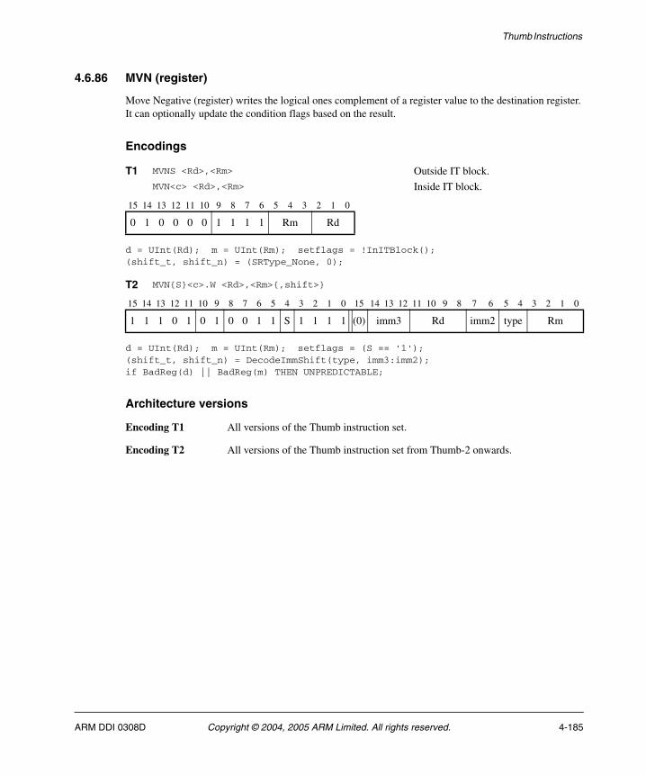
Thumb Instructions
4.6.86 MVN (register)
Move Negative (register) writes the logical ones complement of a register value to the destination register. It can optionally update the condition flags based on the result.
Encodings
d = UInt(Rd); m = UInt(Rm); setflags = !InITBlock();(shift_t, shift_n) = (SRType_None, 0);
d = UInt(Rd); m = UInt(Rm); setflags = (S == '1');(shift_t, shift_n) = DecodeImmShift(type, imm3:imm2);if BadReg(d) || BadReg(m) THEN UNPREDICTABLE;
Architecture versions
Encoding T1 All versions of the Thumb instruction set.
Encoding T2 All versions of the Thumb instruction set from Thumb-2 onwards.
T1 MVNS <Rd>,<Rm> Outside IT block.MVN<c> <Rd>,<Rm> Inside IT block.
15 14 13 12 11 10 9 8 7 6 5 4 3 2 1 0
0 1 0 0 0 0 1 1 1 1 Rm Rd
T2 MVN{S}<c>.W <Rd>,<Rm>{,shift>}
15 14 13 12 11 10 9 8 7 6 5 4 3 2 1 0 15 14 13 12 11 10 9 8 7 6 5 4 3 2 1 0
1 1 1 0 1 0 1 0 0 1 1 S 1 1 1 1 (0) imm3 Rd imm2 type Rm
ARM DDI 0308D Copyright © 2004, 2005 ARM Limited. All rights reserved. 4-185

Thumb Instructions
Assembler syntax
MVN{S}<c><q> <Rd>, <Rm> {, <shift>}
where:
S If present, specifies that the instruction updates the flags. Otherwise, the instruction does not update the flags.
<c><q> See Standard assembler syntax fields on page 4-6.
<Rd> Specifies the destination register.
<Rm> Specifies the register that is optionally shifted and used as the source register.
<shift> Specifies the shift to apply to the value read from <Rm>. If <shift> is omitted, no shift is applied and both encodings are permitted. If <shift> is specified, only encoding T2 is permitted. The possible shifts and how they are encoded are described in Constant shifts applied to a register on page 4-10.
The pre-UAL syntax MVN<c>S is equivalent to MVNS<c>.
Operation
if ConditionPassed() then EncodingSpecificOperations(); (shifted, carry) = Shift_C(R[m], shift_t, shift_n, APSR.C); result = NOT(shifted); R[d] = result; if setflags then APSR.N = result<31>; APSR.Z = IsZeroBit(result); APSR.C = carry; // APSR.V unchanged
Exceptions
None.
4-186 Copyright © 2004, 2005 ARM Limited. All rights reserved. ARM DDI 0308D
Thumb Instructions
4.6.87 NEG
Negate is a pre-UAL synonym for RSB (immediate) with an immediate value of 0. See RSB (immediate) on page 4-249 for details.
ARM DDI 0308D Copyright © 2004, 2005 ARM Limited. All rights reserved. 4-187
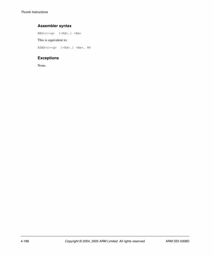
Thumb Instructions
Assembler syntax
NEG<c><q> {<Rd>,} <Rm>
This is equivalent to:
RSBS<c><q> {<Rd>,} <Rm>, #0
Exceptions
None.
4-188 Copyright © 2004, 2005 ARM Limited. All rights reserved. ARM DDI 0308D
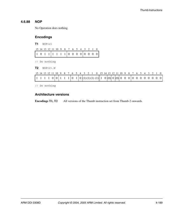
Thumb Instructions
4.6.88 NOP
No Operation does nothing.
Encodings
// Do nothing
// Do nothing
Architecture versions
Encodings T1, T2 All versions of the Thumb instruction set from Thumb-2 onwards.
T1 NOP<c>
15 14 13 12 11 10 9 8 7 6 5 4 3 2 1 0
1 0 1 1 1 1 1 1 0 0 0 0 0 0 0 0
T2 NOP<c>.W
15 14 13 12 11 10 9 8 7 6 5 4 3 2 1 0 15 14 13 12 11 10 9 8 7 6 5 4 3 2 1 0
1 1 1 1 0 0 1 1 1 0 1 0 (1) (1) (1) (1) 1 0 (0) 0 (0) 0 0 0 0 0 0 0 0 0 0 0
ARM DDI 0308D Copyright © 2004, 2005 ARM Limited. All rights reserved. 4-189
Thumb Instructions
Assembler syntax
NOP<c><q>
where:
<c><q> See Standard assembler syntax fields on page 4-6.
Operation
if ConditionPassed() then EncodingSpecificOperations(); // Do nothing
Exceptions
None.
4-190 Copyright © 2004, 2005 ARM Limited. All rights reserved. ARM DDI 0308D
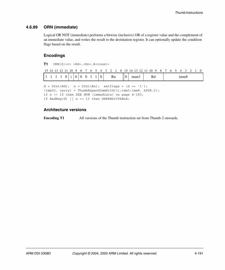
Thumb Instructions
4.6.89 ORN (immediate)
Logical OR NOT (immediate) performs a bitwise (inclusive) OR of a register value and the complement of an immediate value, and writes the result to the destination register. It can optionally update the condition flags based on the result.
Encodings
d = UInt(Rd); n = UInt(Rn); setflags = (S == '1');(imm32, carry) = ThumbExpandImmWithC(i:imm3:imm8, APSR.C);if n == 15 then SEE MVN (immediate) on page 4-183;if BadReg(d) || n == 13 then UNPREDICTABLE;
Architecture versions
Encoding T1 All versions of the Thumb instruction set from Thumb-2 onwards.
T1 ORN{S}<c> <Rd>,<Rn>,#<const>
15 14 13 12 11 10 9 8 7 6 5 4 3 2 1 0 15 14 13 12 11 10 9 8 7 6 5 4 3 2 1 0
1 1 1 1 0 i 0 0 0 1 1 S Rn 0 imm3 Rd imm8
ARM DDI 0308D Copyright © 2004, 2005 ARM Limited. All rights reserved. 4-191
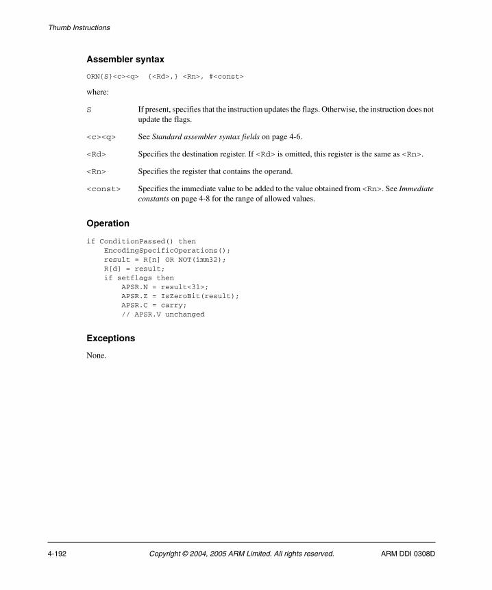
Thumb Instructions
Assembler syntax
ORN{S}<c><q> {<Rd>,} <Rn>, #<const>
where:
S If present, specifies that the instruction updates the flags. Otherwise, the instruction does not update the flags.
<c><q> See Standard assembler syntax fields on page 4-6.
<Rd> Specifies the destination register. If <Rd> is omitted, this register is the same as <Rn>.
<Rn> Specifies the register that contains the operand.
<const> Specifies the immediate value to be added to the value obtained from <Rn>. See Immediate constants on page 4-8 for the range of allowed values.
Operation
if ConditionPassed() then EncodingSpecificOperations(); result = R[n] OR NOT(imm32); R[d] = result; if setflags then APSR.N = result<31>; APSR.Z = IsZeroBit(result); APSR.C = carry; // APSR.V unchanged
Exceptions
None.
4-192 Copyright © 2004, 2005 ARM Limited. All rights reserved. ARM DDI 0308D
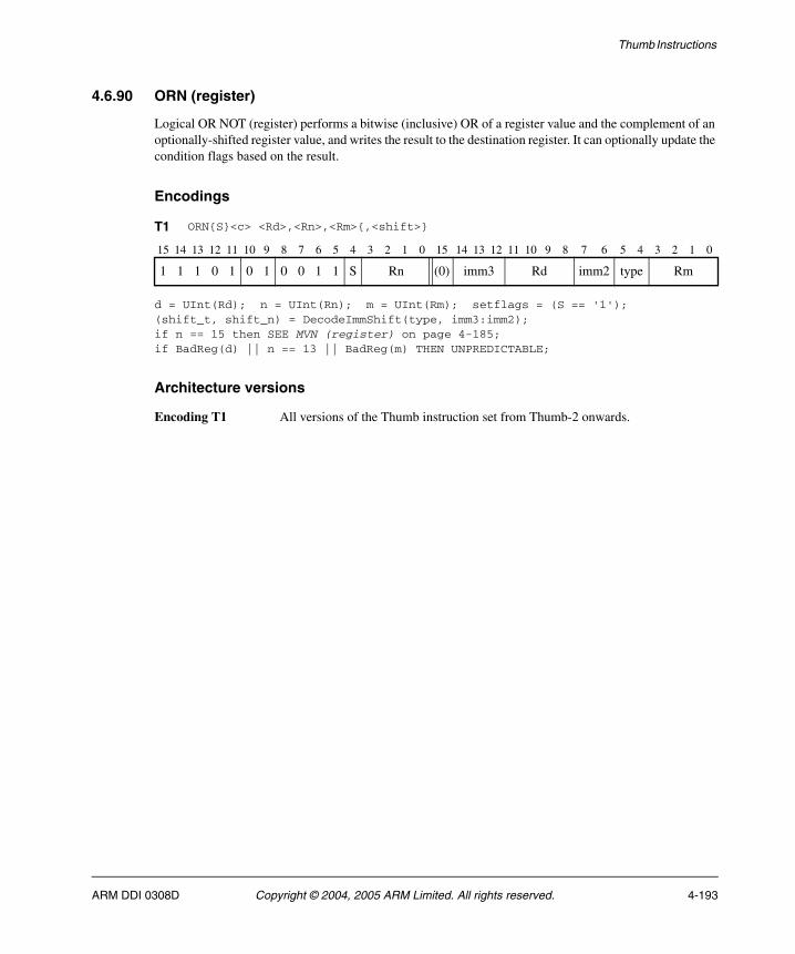
Thumb Instructions
4.6.90 ORN (register)
Logical OR NOT (register) performs a bitwise (inclusive) OR of a register value and the complement of an optionally-shifted register value, and writes the result to the destination register. It can optionally update the condition flags based on the result.
Encodings
d = UInt(Rd); n = UInt(Rn); m = UInt(Rm); setflags = (S == '1');(shift_t, shift_n) = DecodeImmShift(type, imm3:imm2);if n == 15 then SEE MVN (register) on page 4-185;if BadReg(d) || n == 13 || BadReg(m) THEN UNPREDICTABLE;
Architecture versions
Encoding T1 All versions of the Thumb instruction set from Thumb-2 onwards.
T1 ORN{S}<c> <Rd>,<Rn>,<Rm>{,<shift>}
15 14 13 12 11 10 9 8 7 6 5 4 3 2 1 0 15 14 13 12 11 10 9 8 7 6 5 4 3 2 1 0
1 1 1 0 1 0 1 0 0 1 1 S Rn (0) imm3 Rd imm2 type Rm
ARM DDI 0308D Copyright © 2004, 2005 ARM Limited. All rights reserved. 4-193
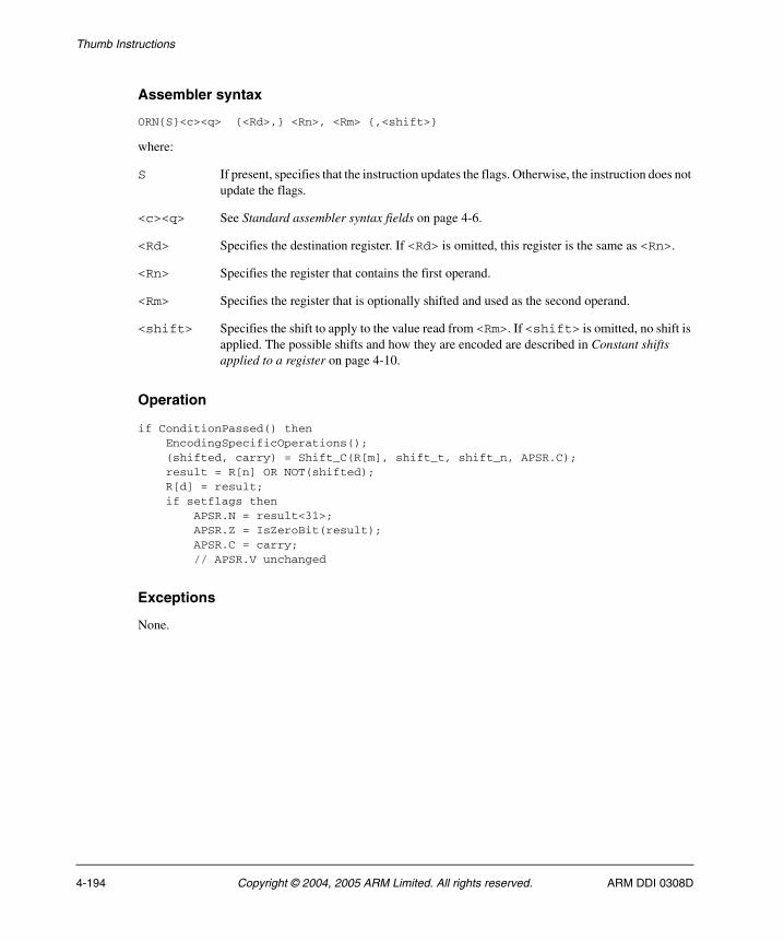
Thumb Instructions
Assembler syntax
ORN{S}<c><q> {<Rd>,} <Rn>, <Rm> {,<shift>}
where:
S If present, specifies that the instruction updates the flags. Otherwise, the instruction does not update the flags.
<c><q> See Standard assembler syntax fields on page 4-6.
<Rd> Specifies the destination register. If <Rd> is omitted, this register is the same as <Rn>.
<Rn> Specifies the register that contains the first operand.
<Rm> Specifies the register that is optionally shifted and used as the second operand.
<shift> Specifies the shift to apply to the value read from <Rm>. If <shift> is omitted, no shift is applied. The possible shifts and how they are encoded are described in Constant shifts applied to a register on page 4-10.
Operation
if ConditionPassed() then EncodingSpecificOperations(); (shifted, carry) = Shift_C(R[m], shift_t, shift_n, APSR.C); result = R[n] OR NOT(shifted); R[d] = result; if setflags then APSR.N = result<31>; APSR.Z = IsZeroBit(result); APSR.C = carry; // APSR.V unchanged
Exceptions
None.
4-194 Copyright © 2004, 2005 ARM Limited. All rights reserved. ARM DDI 0308D
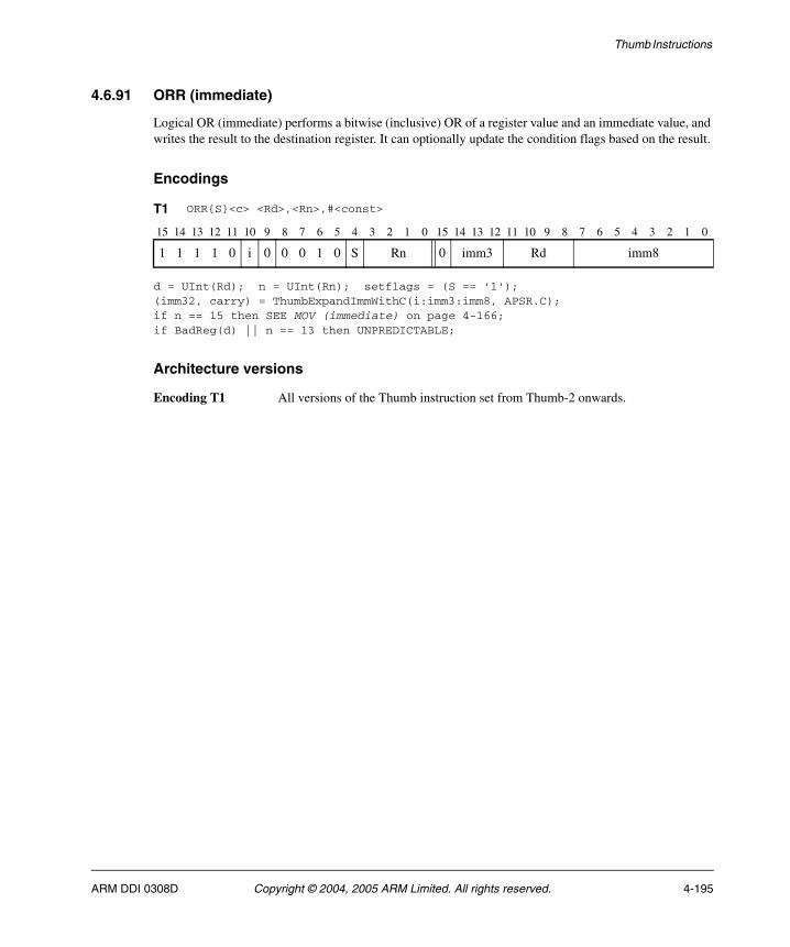
Thumb Instructions
4.6.91 ORR (immediate)
Logical OR (immediate) performs a bitwise (inclusive) OR of a register value and an immediate value, and writes the result to the destination register. It can optionally update the condition flags based on the result.
Encodings
d = UInt(Rd); n = UInt(Rn); setflags = (S == '1');(imm32, carry) = ThumbExpandImmWithC(i:imm3:imm8, APSR.C);if n == 15 then SEE MOV (immediate) on page 4-166;if BadReg(d) || n == 13 then UNPREDICTABLE;
Architecture versions
Encoding T1 All versions of the Thumb instruction set from Thumb-2 onwards.
T1 ORR{S}<c> <Rd>,<Rn>,#<const>
15 14 13 12 11 10 9 8 7 6 5 4 3 2 1 0 15 14 13 12 11 10 9 8 7 6 5 4 3 2 1 0
1 1 1 1 0 i 0 0 0 1 0 S Rn 0 imm3 Rd imm8
ARM DDI 0308D Copyright © 2004, 2005 ARM Limited. All rights reserved. 4-195

Thumb Instructions
Assembler syntax
ORR{S}<c><q> {<Rd>,} <Rn>, #<const>
where:
S If present, specifies that the instruction updates the flags. Otherwise, the instruction does not update the flags.
<c><q> See Standard assembler syntax fields on page 4-6.
<Rd> Specifies the destination register. If <Rd> is omitted, this register is the same as <Rn>.
<Rn> Specifies the register that contains the operand.
<const> Specifies the immediate value to be added to the value obtained from <Rn>. See Immediate constants on page 4-8 for the range of allowed values.
The pre-UAL syntax ORR<c>S is equivalent to ORRS<c>.
Operation
if ConditionPassed() then EncodingSpecificOperations(); result = R[n] OR imm32; R[d] = result; if setflags then APSR.N = result<31>; APSR.Z = IsZeroBit(result); APSR.C = carry; // APSR.V unchanged
Exceptions
None.
4-196 Copyright © 2004, 2005 ARM Limited. All rights reserved. ARM DDI 0308D
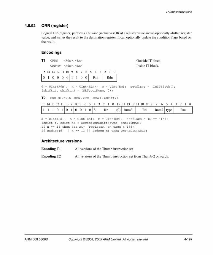
Thumb Instructions
4.6.92 ORR (register)
Logical OR (register) performs a bitwise (inclusive) OR of a register value and an optionally-shifted register value, and writes the result to the destination register. It can optionally update the condition flags based on the result.
Encodings
d = UInt(Rdn); n = UInt(Rdn); m = UInt(Rm); setflags = !InITBlock();(shift_t, shift_n) = (SRType_None, 0);
d = UInt(Rd); n = UInt(Rn); m = UInt(Rm); setflags = (S == '1');(shift_t, shift_n) = DecodeImmShift(type, imm3:imm2);if n == 15 then SEE MOV (register) on page 4-168;if BadReg(d) || n == 13 || BadReg(m) THEN UNPREDICTABLE;
Architecture versions
Encoding T1 All versions of the Thumb instruction set
Encoding T2 All versions of the Thumb instruction set from Thumb-2 onwards.
T1 ORRS <Rdn>,<Rm> Outside IT block.ORR<c> <Rdn>,<Rm> Inside IT block.
15 14 13 12 11 10 9 8 7 6 5 4 3 2 1 0
0 1 0 0 0 0 1 1 0 0 Rm Rdn
T2 ORR{S}<c>.W <Rd>,<Rn>,<Rm>{,<shift>}
15 14 13 12 11 10 9 8 7 6 5 4 3 2 1 0 15 14 13 12 11 10 9 8 7 6 5 4 3 2 1 0
1 1 1 0 1 0 1 0 0 1 0 S Rn (0) imm3 Rd imm2 type Rm
ARM DDI 0308D Copyright © 2004, 2005 ARM Limited. All rights reserved. 4-197
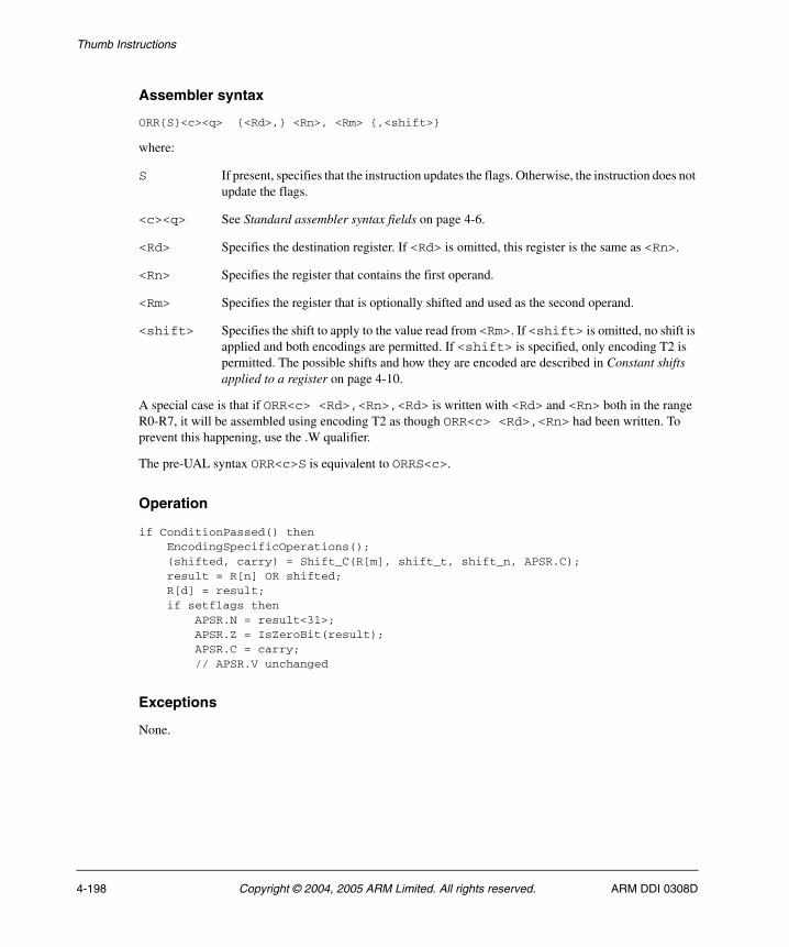
Thumb Instructions
Assembler syntax
ORR{S}<c><q> {<Rd>,} <Rn>, <Rm> {,<shift>}
where:
S If present, specifies that the instruction updates the flags. Otherwise, the instruction does not update the flags.
<c><q> See Standard assembler syntax fields on page 4-6.
<Rd> Specifies the destination register. If <Rd> is omitted, this register is the same as <Rn>.
<Rn> Specifies the register that contains the first operand.
<Rm> Specifies the register that is optionally shifted and used as the second operand.
<shift> Specifies the shift to apply to the value read from <Rm>. If <shift> is omitted, no shift is applied and both encodings are permitted. If <shift> is specified, only encoding T2 is permitted. The possible shifts and how they are encoded are described in Constant shifts applied to a register on page 4-10.
A special case is that if ORR<c> <Rd>,<Rn>,<Rd> is written with <Rd> and <Rn> both in the range R0-R7, it will be assembled using encoding T2 as though ORR<c> <Rd>,<Rn> had been written. To prevent this happening, use the .W qualifier.
The pre-UAL syntax ORR<c>S is equivalent to ORRS<c>.
Operation
if ConditionPassed() then EncodingSpecificOperations(); (shifted, carry) = Shift_C(R[m], shift_t, shift_n, APSR.C); result = R[n] OR shifted; R[d] = result; if setflags then APSR.N = result<31>; APSR.Z = IsZeroBit(result); APSR.C = carry; // APSR.V unchanged
Exceptions
None.
4-198 Copyright © 2004, 2005 ARM Limited. All rights reserved. ARM DDI 0308D
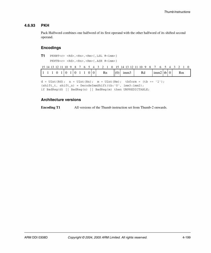
Thumb Instructions
4.6.93 PKH
Pack Halfword combines one halfword of its first operand with the other halfword of its shifted second operand.
Encodings
d = UInt(Rd); n = UInt(Rn); m = UInt(Rm); tbform = (tb == '1');(shift_t, shift_n) = DecodeImmShift(tb:'0', imm3:imm2);if BadReg(d) || BadReg(n) || BadReg(m) then UNPREDICTABLE;
Architecture versions
Encoding T1 All versions of the Thumb instruction set from Thumb-2 onwards.
T1 PKHBT<c> <Rd>,<Rn>,<Rm>{,LSL #<imm>}
PKHTB<c> <Rd>,<Rn>,<Rm>{,ASR #<imm>}
15 14 13 12 11 10 9 8 7 6 5 4 3 2 1 0 15 14 13 12 11 10 9 8 7 6 5 4 3 2 1 0
1 1 1 0 1 0 1 0 1 1 0 0 Rn (0) imm3 Rd imm2 tb 0 Rm
ARM DDI 0308D Copyright © 2004, 2005 ARM Limited. All rights reserved. 4-199
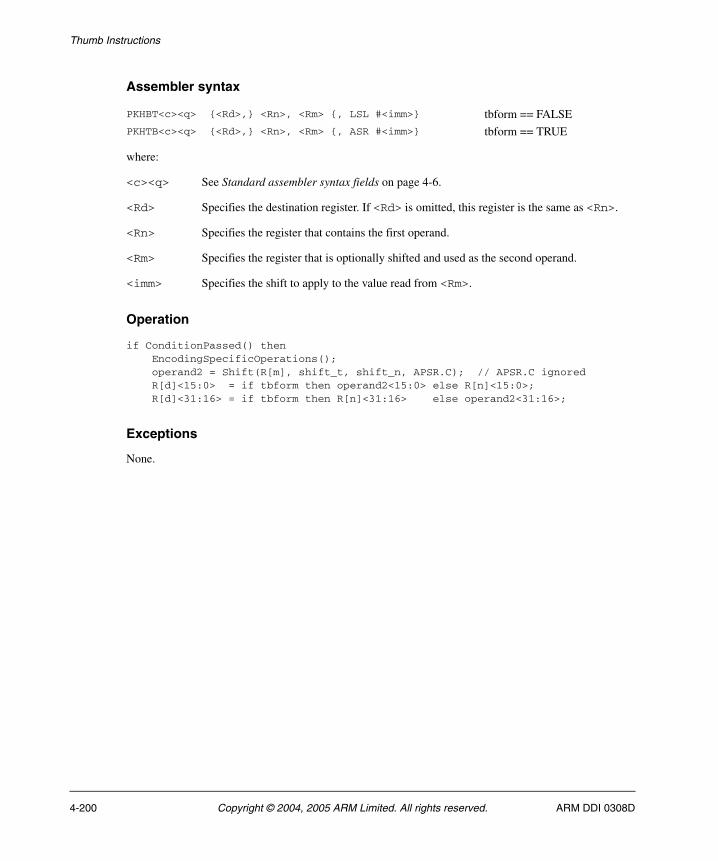
Thumb Instructions
Assembler syntax
where:
<c><q> See Standard assembler syntax fields on page 4-6.
<Rd> Specifies the destination register. If <Rd> is omitted, this register is the same as <Rn>.
<Rn> Specifies the register that contains the first operand.
<Rm> Specifies the register that is optionally shifted and used as the second operand.
<imm> Specifies the shift to apply to the value read from <Rm>.
Operation
if ConditionPassed() then EncodingSpecificOperations(); operand2 = Shift(R[m], shift_t, shift_n, APSR.C); // APSR.C ignored R[d]<15:0> = if tbform then operand2<15:0> else R[n]<15:0>; R[d]<31:16> = if tbform then R[n]<31:16> else operand2<31:16>;
Exceptions
None.
PKHBT<c><q> {<Rd>,} <Rn>, <Rm> {, LSL #<imm>} tbform == FALSEPKHTB<c><q> {<Rd>,} <Rn>, <Rm> {, ASR #<imm>} tbform == TRUE
4-200 Copyright © 2004, 2005 ARM Limited. All rights reserved. ARM DDI 0308D

Thumb Instructions
4.6.94 PLD (immediate)
Preload Data signals the memory system that data memory accesses from a specified address are likely in the near future. The memory system can respond by taking actions that are expected to speed up the memory accesses when they do occur, such as pre-loading the cache line containing the specified address into the data cache.
Encodings
n = UInt(Rn); imm32 = ZeroExtend(imm12, 32); add = TRUE;if n == 15 then SEE encoding T3;
n = UInt(Rn); imm32 = ZeroExtend(imm8, 32); add = FALSE;if n == 15 then SEE encoding T3;
n = 15; imm32 = ZeroExtend(imm12, 32); add = (U == '1');
Architecture versions
Encodings T1, T2, T3
All versions of the Thumb instruction set from Thumb-2 onwards.
T1 PLD<c> [<Rn>,#<imm12>]
15 14 13 12 11 10 9 8 7 6 5 4 3 2 1 0 15 14 13 12 11 10 9 8 7 6 5 4 3 2 1 0
1 1 1 1 1 0 0 0 1 0 0 1 Rn 1 1 1 1 imm12
T2 PLD<c> [<Rn>,#-<imm8>]
15 14 13 12 11 10 9 8 7 6 5 4 3 2 1 0 15 14 13 12 11 10 9 8 7 6 5 4 3 2 1 0
1 1 1 1 1 0 0 0 0 0 0 1 Rn 1 1 1 1 1 1 0 0 imm8
T3 PLD<c> [PC,#+/-<imm12>]
15 14 13 12 11 10 9 8 7 6 5 4 3 2 1 0 15 14 13 12 11 10 9 8 7 6 5 4 3 2 1 0
1 1 1 1 1 0 0 0 U 0 0 1 1 1 1 1 1 1 1 1 imm12
ARM DDI 0308D Copyright © 2004, 2005 ARM Limited. All rights reserved. 4-201
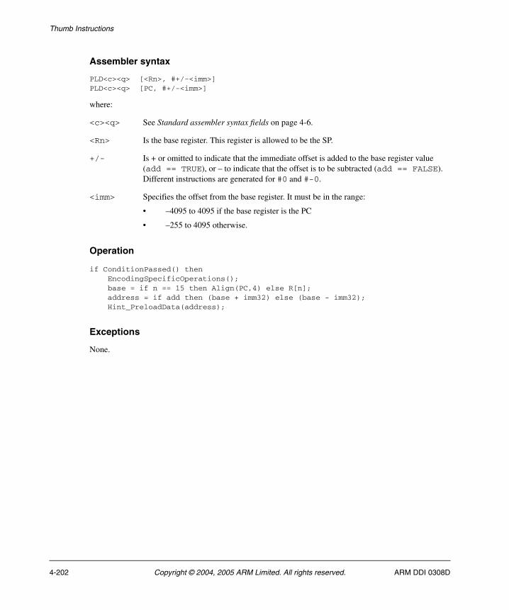
Thumb Instructions
Assembler syntax
PLD<c><q> [<Rn>, #+/-<imm>]PLD<c><q> [PC, #+/-<imm>]
where:
<c><q> See Standard assembler syntax fields on page 4-6.
<Rn> Is the base register. This register is allowed to be the SP.
+/- Is + or omitted to indicate that the immediate offset is added to the base register value (add == TRUE), or – to indicate that the offset is to be subtracted (add == FALSE). Different instructions are generated for #0 and #-0.
<imm> Specifies the offset from the base register. It must be in the range:
• –4095 to 4095 if the base register is the PC
• –255 to 4095 otherwise.
Operation
if ConditionPassed() then EncodingSpecificOperations(); base = if n == 15 then Align(PC,4) else R[n]; address = if add then (base + imm32) else (base - imm32); Hint_PreloadData(address);
Exceptions
None.
4-202 Copyright © 2004, 2005 ARM Limited. All rights reserved. ARM DDI 0308D
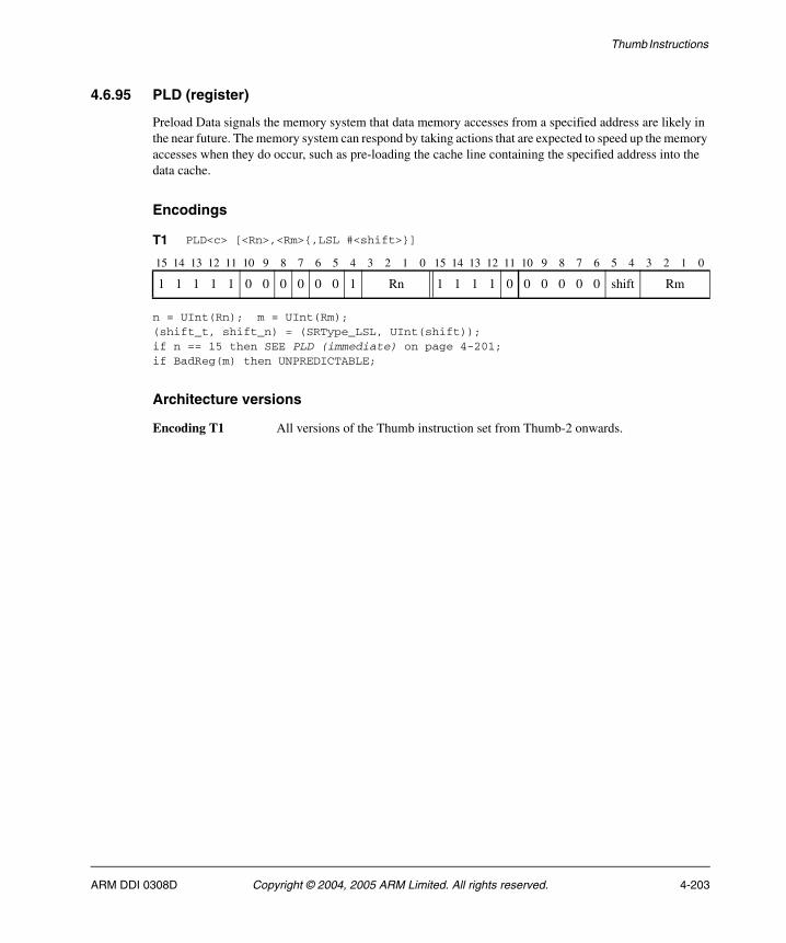
Thumb Instructions
4.6.95 PLD (register)
Preload Data signals the memory system that data memory accesses from a specified address are likely in the near future. The memory system can respond by taking actions that are expected to speed up the memory accesses when they do occur, such as pre-loading the cache line containing the specified address into the data cache.
Encodings
n = UInt(Rn); m = UInt(Rm);(shift_t, shift_n) = (SRType_LSL, UInt(shift));if n == 15 then SEE PLD (immediate) on page 4-201;if BadReg(m) then UNPREDICTABLE;
Architecture versions
Encoding T1 All versions of the Thumb instruction set from Thumb-2 onwards.
T1 PLD<c> [<Rn>,<Rm>{,LSL #<shift>}]
15 14 13 12 11 10 9 8 7 6 5 4 3 2 1 0 15 14 13 12 11 10 9 8 7 6 5 4 3 2 1 0
1 1 1 1 1 0 0 0 0 0 0 1 Rn 1 1 1 1 0 0 0 0 0 0 shift Rm
ARM DDI 0308D Copyright © 2004, 2005 ARM Limited. All rights reserved. 4-203

Thumb Instructions
Assembler syntax
PLD<c><q> [<Rn>, <Rm> {, LSL #<shift>}]
where:
<c><q> See Standard assembler syntax fields on page 4-6.
<Rn> Is the base register. This register is allowed to be the SP.
<Rm> Is the optionally shifted offset register.
<shift> Specifies the shift to apply to the value read from <Rm>, in the range 0-3. If this option is omitted, a shift by 0 is assumed.
Operation
if ConditionPassed() then EncodingSpecificOperations(); address = R[n] + Shift(R[m], shift_t, shift_n, APSR.C); Hint_PreloadData(address);
Exceptions
None.
4-204 Copyright © 2004, 2005 ARM Limited. All rights reserved. ARM DDI 0308D
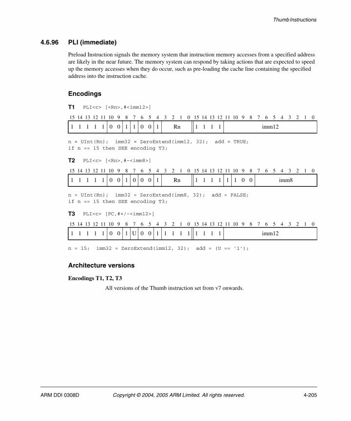
Thumb Instructions
4.6.96 PLI (immediate)
Preload Instruction signals the memory system that instruction memory accesses from a specified address are likely in the near future. The memory system can respond by taking actions that are expected to speed up the memory accesses when they do occur, such as pre-loading the cache line containing the specified address into the instruction cache.
Encodings
n = UInt(Rn); imm32 = ZeroExtend(imm12, 32); add = TRUE;if n == 15 then SEE encoding T3;
n = UInt(Rn); imm32 = ZeroExtend(imm8, 32); add = FALSE;if n == 15 then SEE encoding T3;
n = 15; imm32 = ZeroExtend(imm12, 32); add = (U == '1');
Architecture versions
Encodings T1, T2, T3
All versions of the Thumb instruction set from v7 onwards.
T1 PLI<c> [<Rn>,#<imm12>]
15 14 13 12 11 10 9 8 7 6 5 4 3 2 1 0 15 14 13 12 11 10 9 8 7 6 5 4 3 2 1 0
1 1 1 1 1 0 0 1 1 0 0 1 Rn 1 1 1 1 imm12
T2 PLI<c> [<Rn>,#-<imm8>]
15 14 13 12 11 10 9 8 7 6 5 4 3 2 1 0 15 14 13 12 11 10 9 8 7 6 5 4 3 2 1 0
1 1 1 1 1 0 0 1 0 0 0 1 Rn 1 1 1 1 1 1 0 0 imm8
T3 PLI<c> [PC,#+/-<imm12>]
15 14 13 12 11 10 9 8 7 6 5 4 3 2 1 0 15 14 13 12 11 10 9 8 7 6 5 4 3 2 1 0
1 1 1 1 1 0 0 1 U 0 0 1 1 1 1 1 1 1 1 1 imm12
ARM DDI 0308D Copyright © 2004, 2005 ARM Limited. All rights reserved. 4-205

Thumb Instructions
Assembler syntax
PLI<c><q> [<Rn>, #+/-<imm>]PLI<c><q> [PC, #+/-<imm>]
where:
<c><q> See Standard assembler syntax fields on page 4-6.
<Rn> Is the base register. This register is allowed to be the SP.
+/- Is + or omitted to indicate that the immediate offset is added to the base register value (add == TRUE), or – to indicate that the offset is to be subtracted (add == FALSE). Different instructions are generated for #0 and #-0.
<imm> Specifies the offset from the base register. It must be in the range:
• –4095 to 4095 if the base register is the PC
• –255 to 4095 otherwise.
Operation
if ConditionPassed() then EncodingSpecificOperations(); base = if n == 15 then Align(PC,4) else R[n]; address = if add then (base + imm32) else (base - imm32); Hint_PreloadInstr(address);
Exceptions
None.
4-206 Copyright © 2004, 2005 ARM Limited. All rights reserved. ARM DDI 0308D
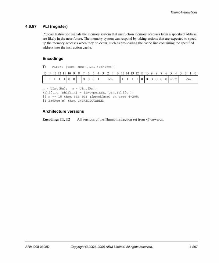
Thumb Instructions
4.6.97 PLI (register)
Preload Instruction signals the memory system that instruction memory accesses from a specified address are likely in the near future. The memory system can respond by taking actions that are expected to speed up the memory accesses when they do occur, such as pre-loading the cache line containing the specified address into the instruction cache.
Encodings
n = UInt(Rn); m = UInt(Rm);(shift_t, shift_n) = (SRType_LSL, UInt(shift));if n == 15 then SEE PLI (immediate) on page 4-205;if BadReg(m) then UNPREDICTABLE;
Architecture versions
Encodings T1, T2 All versions of the Thumb instruction set from v7 onwards.
T1 PLI<c> [<Rn>,<Rm>{,LSL #<shift>}]
15 14 13 12 11 10 9 8 7 6 5 4 3 2 1 0 15 14 13 12 11 10 9 8 7 6 5 4 3 2 1 0
1 1 1 1 1 0 0 1 0 0 0 1 Rn 1 1 1 1 0 0 0 0 0 0 shift Rm
ARM DDI 0308D Copyright © 2004, 2005 ARM Limited. All rights reserved. 4-207
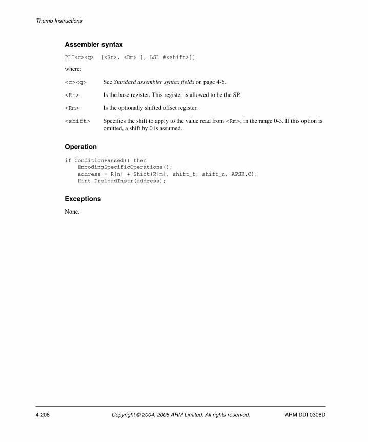
Thumb Instructions
Assembler syntax
PLI<c><q> [<Rn>, <Rm> {, LSL #<shift>}]
where:
<c><q> See Standard assembler syntax fields on page 4-6.
<Rn> Is the base register. This register is allowed to be the SP.
<Rm> Is the optionally shifted offset register.
<shift> Specifies the shift to apply to the value read from <Rm>, in the range 0-3. If this option is omitted, a shift by 0 is assumed.
Operation
if ConditionPassed() then EncodingSpecificOperations(); address = R[n] + Shift(R[m], shift_t, shift_n, APSR.C); Hint_PreloadInstr(address);
Exceptions
None.
4-208 Copyright © 2004, 2005 ARM Limited. All rights reserved. ARM DDI 0308D
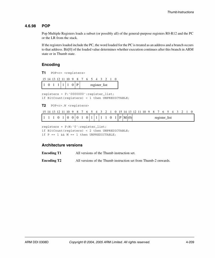
Thumb Instructions
4.6.98 POP
Pop Multiple Registers loads a subset (or possibly all) of the general-purpose registers R0-R12 and the PC or the LR from the stack.
If the registers loaded include the PC, the word loaded for the PC is treated as an address and a branch occurs to that address. Bit[0] of the loaded value determines whether execution continues after this branch in ARM state or in Thumb state.
Encoding
registers = P:'0000000':register_list;if BitCount(registers) < 1 then UNPREDICTABLE;
registers = P:M:'0':register_list;if BitCount(registers) < 2 then UNPREDICTABLE;if P == 1 && M == 1 then UNPREDICTABLE;
Architecture versions
Encoding T1 All versions of the Thumb instruction set.
Encoding T2 All versions of the Thumb instruction set from Thumb-2 onwards.
T1 POP<c> <registers>
15 14 13 12 11 10 9 8 7 6 5 4 3 2 1 0
1 0 1 1 1 1 0 P register_list
T2 POP<c>.W <registers>
15 14 13 12 11 10 9 8 7 6 5 4 3 2 1 0 15 14 13 12 11 10 9 8 7 6 5 4 3 2 1 0
1 1 1 0 1 0 0 0 1 0 1 1 1 1 0 1 P M (0) register_list
ARM DDI 0308D Copyright © 2004, 2005 ARM Limited. All rights reserved. 4-209
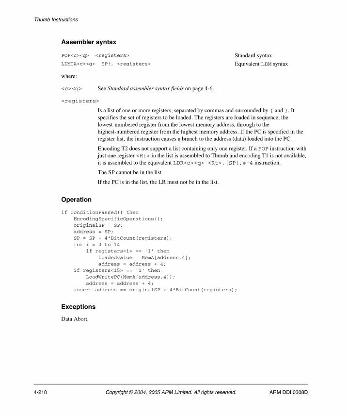
Thumb Instructions
Assembler syntax
where:
<c><q> See Standard assembler syntax fields on page 4-6.
<registers>
Is a list of one or more registers, separated by commas and surrounded by { and }. It specifies the set of registers to be loaded. The registers are loaded in sequence, the lowest-numbered register from the lowest memory address, through to the highest-numbered register from the highest memory address. If the PC is specified in the register list, the instruction causes a branch to the address (data) loaded into the PC.
Encoding T2 does not support a list containing only one register. If a POP instruction with just one register <Rt> in the list is assembled to Thumb and encoding T1 is not available, it is assembled to the equivalent LDR<c><q> <Rt>,[SP],#-4 instruction.
The SP cannot be in the list.
If the PC is in the list, the LR must not be in the list.
Operation
if ConditionPassed() then EncodingSpecificOperations(); originalSP = SP; address = SP; SP = SP + 4*BitCount(registers); for i = 0 to 14 if registers<i> == '1' then loadedvalue = MemA[address,4]; address = address + 4; if registers<15> == '1' then LoadWritePC(MemA[address,4]); address = address + 4; assert address == originalSP + 4*BitCount(registers);
Exceptions
Data Abort.
POP<c><q> <registers> Standard syntaxLDMIA<c><q> SP!, <registers> Equivalent LDM syntax
4-210 Copyright © 2004, 2005 ARM Limited. All rights reserved. ARM DDI 0308D
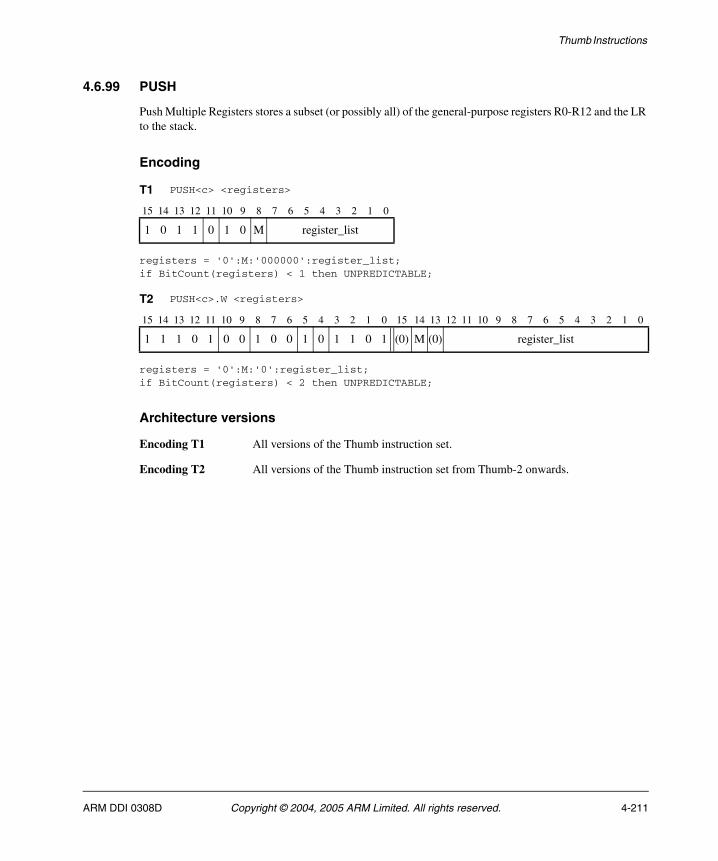
Thumb Instructions
4.6.99 PUSH
Push Multiple Registers stores a subset (or possibly all) of the general-purpose registers R0-R12 and the LR to the stack.
Encoding
registers = '0':M:'000000':register_list;if BitCount(registers) < 1 then UNPREDICTABLE;
registers = '0':M:'0':register_list;if BitCount(registers) < 2 then UNPREDICTABLE;
Architecture versions
Encoding T1 All versions of the Thumb instruction set.
Encoding T2 All versions of the Thumb instruction set from Thumb-2 onwards.
T1 PUSH<c> <registers>
15 14 13 12 11 10 9 8 7 6 5 4 3 2 1 0
1 0 1 1 0 1 0 M register_list
T2 PUSH<c>.W <registers>
15 14 13 12 11 10 9 8 7 6 5 4 3 2 1 0 15 14 13 12 11 10 9 8 7 6 5 4 3 2 1 0
1 1 1 0 1 0 0 1 0 0 1 0 1 1 0 1 (0) M (0) register_list
ARM DDI 0308D Copyright © 2004, 2005 ARM Limited. All rights reserved. 4-211
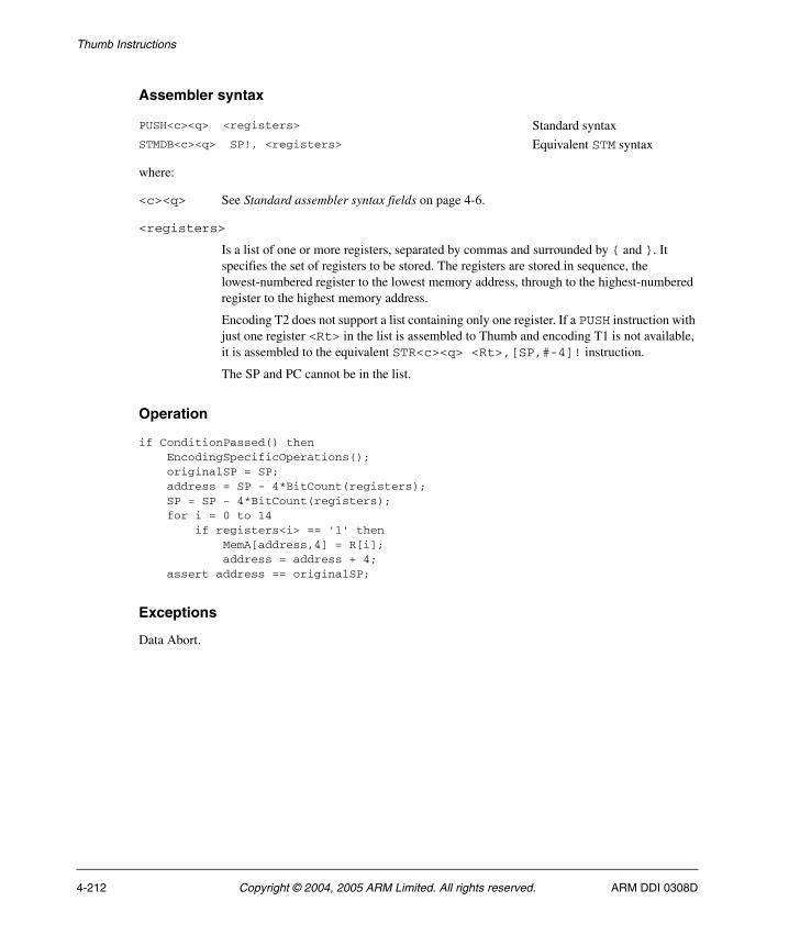
Thumb Instructions
Assembler syntax
where:
<c><q> See Standard assembler syntax fields on page 4-6.
<registers>
Is a list of one or more registers, separated by commas and surrounded by { and }. It specifies the set of registers to be stored. The registers are stored in sequence, the lowest-numbered register to the lowest memory address, through to the highest-numbered register to the highest memory address.
Encoding T2 does not support a list containing only one register. If a PUSH instruction with just one register <Rt> in the list is assembled to Thumb and encoding T1 is not available, it is assembled to the equivalent STR<c><q> <Rt>,[SP,#-4]! instruction.
The SP and PC cannot be in the list.
Operation
if ConditionPassed() then EncodingSpecificOperations(); originalSP = SP; address = SP - 4*BitCount(registers); SP = SP - 4*BitCount(registers); for i = 0 to 14 if registers<i> == '1' then MemA[address,4] = R[i]; address = address + 4; assert address == originalSP;
Exceptions
Data Abort.
PUSH<c><q> <registers> Standard syntaxSTMDB<c><q> SP!, <registers> Equivalent STM syntax
4-212 Copyright © 2004, 2005 ARM Limited. All rights reserved. ARM DDI 0308D
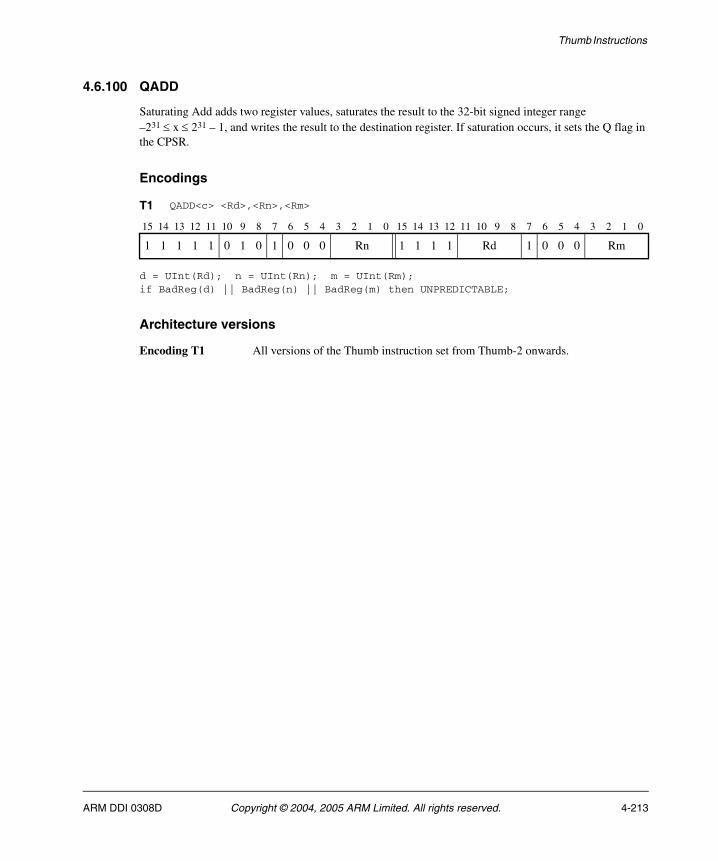
Thumb Instructions
4.6.100 QADD
Saturating Add adds two register values, saturates the result to the 32-bit signed integer range –231 ≤ x ≤ 231 – 1, and writes the result to the destination register. If saturation occurs, it sets the Q flag in the CPSR.
Encodings
d = UInt(Rd); n = UInt(Rn); m = UInt(Rm);if BadReg(d) || BadReg(n) || BadReg(m) then UNPREDICTABLE;
Architecture versions
Encoding T1 All versions of the Thumb instruction set from Thumb-2 onwards.
T1 QADD<c> <Rd>,<Rn>,<Rm>
15 14 13 12 11 10 9 8 7 6 5 4 3 2 1 0 15 14 13 12 11 10 9 8 7 6 5 4 3 2 1 0
1 1 1 1 1 0 1 0 1 0 0 0 Rn 1 1 1 1 Rd 1 0 0 0 Rm
ARM DDI 0308D Copyright © 2004, 2005 ARM Limited. All rights reserved. 4-213

Thumb Instructions
Assembler syntax
QADD<c><q> {<Rd>,} <Rn>, <Rm>
where:
<c><q> See Standard assembler syntax fields on page 4-6.
<Rd> Specifies the destination register. If <Rd> is omitted, this register is the same as <Rn>.
<Rn> Specifies the register that contains the first operand.
<Rm> Specifies the register that contains the second operand.
Operation
if ConditionPassed() then EncodingSpecificOperations(); (R[d], sat) = SignedSatQ(SInt(R[m]) + SInt(R[n]), 32); if sat then APSR.Q = '1';
Exceptions
None.
4-214 Copyright © 2004, 2005 ARM Limited. All rights reserved. ARM DDI 0308D
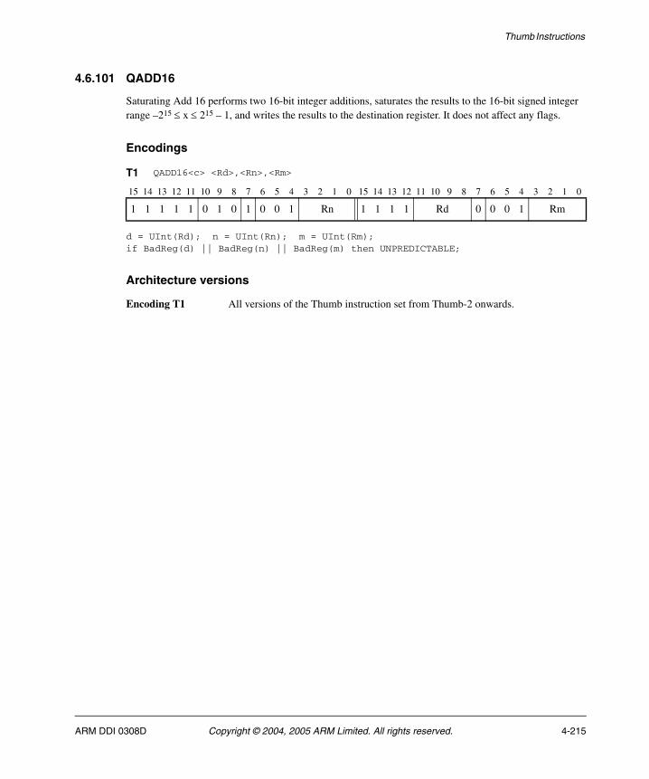
Thumb Instructions
4.6.101 QADD16
Saturating Add 16 performs two 16-bit integer additions, saturates the results to the 16-bit signed integer range –215 ≤ x ≤ 215 – 1, and writes the results to the destination register. It does not affect any flags.
Encodings
d = UInt(Rd); n = UInt(Rn); m = UInt(Rm);if BadReg(d) || BadReg(n) || BadReg(m) then UNPREDICTABLE;
Architecture versions
Encoding T1 All versions of the Thumb instruction set from Thumb-2 onwards.
T1 QADD16<c> <Rd>,<Rn>,<Rm>
15 14 13 12 11 10 9 8 7 6 5 4 3 2 1 0 15 14 13 12 11 10 9 8 7 6 5 4 3 2 1 0
1 1 1 1 1 0 1 0 1 0 0 1 Rn 1 1 1 1 Rd 0 0 0 1 Rm
ARM DDI 0308D Copyright © 2004, 2005 ARM Limited. All rights reserved. 4-215

Thumb Instructions
Assembler syntax
QADD16<c><q> {<Rd>,} <Rn>, <Rm>
where:
<c><q> See Standard assembler syntax fields on page 4-6.
<Rd> Specifies the destination register. If <Rd> is omitted, this register is the same as <Rn>.
<Rn> Specifies the register that contains the first operand.
<Rm> Specifies the register that contains the second operand.
Operation
if ConditionPassed() then EncodingSpecificOperations(); sum1 = SInt(R[n]<15:0>) + SInt(R[m]<15:0>); sum2 = SInt(R[n]<31:16>) + SInt(R[m]<31:16>); R[d]<15:0> = SignedSat(sum1, 16); R[d]<31:16> = SignedSat(sum2, 16);
Exceptions
None.
4-216 Copyright © 2004, 2005 ARM Limited. All rights reserved. ARM DDI 0308D
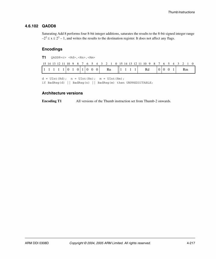
Thumb Instructions
4.6.102 QADD8
Saturating Add 8 performs four 8-bit integer additions, saturates the results to the 8-bit signed integer range –27 ≤ x ≤ 27 – 1, and writes the results to the destination register. It does not affect any flags.
Encodings
d = UInt(Rd); n = UInt(Rn); m = UInt(Rm);if BadReg(d) || BadReg(n) || BadReg(m) then UNPREDICTABLE;
Architecture versions
Encoding T1 All versions of the Thumb instruction set from Thumb-2 onwards.
T1 QADD8<c> <Rd>,<Rn>,<Rm>
15 14 13 12 11 10 9 8 7 6 5 4 3 2 1 0 15 14 13 12 11 10 9 8 7 6 5 4 3 2 1 0
1 1 1 1 1 0 1 0 1 0 0 0 Rn 1 1 1 1 Rd 0 0 0 1 Rm
ARM DDI 0308D Copyright © 2004, 2005 ARM Limited. All rights reserved. 4-217
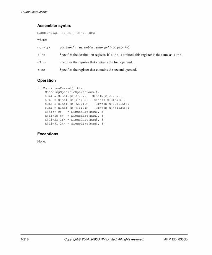
Thumb Instructions
Assembler syntax
QADD8<c><q> {<Rd>,} <Rn>, <Rm>
where:
<c><q> See Standard assembler syntax fields on page 4-6.
<Rd> Specifies the destination register. If <Rd> is omitted, this register is the same as <Rn>.
<Rn> Specifies the register that contains the first operand.
<Rm> Specifies the register that contains the second operand.
Operation
if ConditionPassed() then EncodingSpecificOperations(); sum1 = SInt(R[n]<7:0>) + SInt(R[m]<7:0>); sum2 = SInt(R[n]<15:8>) + SInt(R[m]<15:8>); sum3 = SInt(R[n]<23:16>) + SInt(R[m]<23:16>); sum4 = SInt(R[n]<31:24>) + SInt(R[m]<31:24>); R[d]<7:0> = SignedSat(sum1, 8); R[d]<15:8> = SignedSat(sum2, 8); R[d]<23:16> = SignedSat(sum3, 8); R[d]<31:24> = SignedSat(sum4, 8);
Exceptions
None.
4-218 Copyright © 2004, 2005 ARM Limited. All rights reserved. ARM DDI 0308D

Thumb Instructions
4.6.103 QASX
Saturating Add and Subtract with Exchange exchanges the two halfwords of the second operand, performs one 16-bit integer addition and one 16-bit subtraction, saturates the results to the 16-bit signed integer range –215 ≤ x ≤ 215 – 1, and writes the results to the destination register. It does not affect any flags.
Encodings
d = UInt(Rd); n = UInt(Rn); m = UInt(Rm);if BadReg(d) || BadReg(n) || BadReg(m) then UNPREDICTABLE;
Architecture versions
Encoding T1 All versions of the Thumb instruction set from Thumb-2 onwards.
T1 QASX<c> <Rd>,<Rn>,<Rm>
15 14 13 12 11 10 9 8 7 6 5 4 3 2 1 0 15 14 13 12 11 10 9 8 7 6 5 4 3 2 1 0
1 1 1 1 1 0 1 0 1 0 1 0 Rn 1 1 1 1 Rd 0 0 0 1 Rm
ARM DDI 0308D Copyright © 2004, 2005 ARM Limited. All rights reserved. 4-219

Thumb Instructions
Assembler syntax
QASX<c><q> {<Rd>,} <Rn>, <Rm>
where:
<c><q> See Standard assembler syntax fields on page 4-6.
<Rd> Specifies the destination register. If <Rd> is omitted, this register is the same as <Rn>.
<Rn> Specifies the register that contains the first operand.
<Rm> Specifies the register that contains the second operand.
Operation
if ConditionPassed() then EncodingSpecificOperations(); diff = SInt(R[n]<15:0>) - SInt(R[m]<31:16>); sum = SInt(R[n]<31:16>) + SInt(R[m]<15:0>); R[d]<15:0> = SignedSat(diff, 16); R[d]<31:16> = SignedSat(sum, 16);
Exceptions
None.
4-220 Copyright © 2004, 2005 ARM Limited. All rights reserved. ARM DDI 0308D
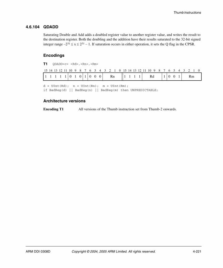
Thumb Instructions
4.6.104 QDADD
Saturating Double and Add adds a doubled register value to another register value, and writes the result to the destination register. Both the doubling and the addition have their results saturated to the 32-bit signed integer range –231 ≤ x ≤ 231 – 1. If saturation occurs in either operation, it sets the Q flag in the CPSR.
Encodings
d = UInt(Rd); n = UInt(Rn); m = UInt(Rm);if BadReg(d) || BadReg(n) || BadReg(m) then UNPREDICTABLE;
Architecture versions
Encoding T1 All versions of the Thumb instruction set from Thumb-2 onwards.
T1 QDADD<c> <Rd>,<Rn>,<Rm>
15 14 13 12 11 10 9 8 7 6 5 4 3 2 1 0 15 14 13 12 11 10 9 8 7 6 5 4 3 2 1 0
1 1 1 1 1 0 1 0 1 0 0 0 Rn 1 1 1 1 Rd 1 0 0 1 Rm
ARM DDI 0308D Copyright © 2004, 2005 ARM Limited. All rights reserved. 4-221

Thumb Instructions
Assembler syntax
QDADD<c><q> {<Rd>,} <Rn>, <Rm>
where:
<c><q> See Standard assembler syntax fields on page 4-6.
<Rd> Specifies the destination register. If <Rd> is omitted, this register is the same as <Rn>.
<Rn> Specifies the register that contains the first operand.
<Rm> Specifies the register that contains the second operand.
Operation
if ConditionPassed() then EncodingSpecificOperations(); (doubled, sat1) = SignedSatQ(2 * SInt(R[n]), 32); (R[d], sat2) = SignedSatQ(SInt(R[m]) + SInt(doubled), 32); if sat1 || sat2 then APSR.Q = '1';
Exceptions
None.
4-222 Copyright © 2004, 2005 ARM Limited. All rights reserved. ARM DDI 0308D
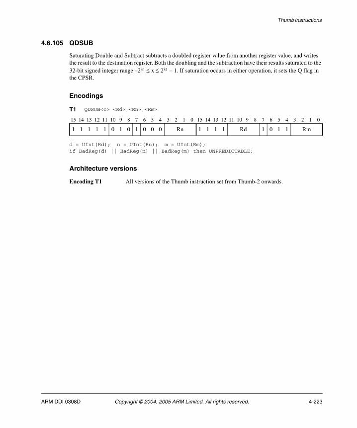
Thumb Instructions
4.6.105 QDSUB
Saturating Double and Subtract subtracts a doubled register value from another register value, and writes the result to the destination register. Both the doubling and the subtraction have their results saturated to the 32-bit signed integer range –231 ≤ x ≤ 231 – 1. If saturation occurs in either operation, it sets the Q flag in the CPSR.
Encodings
d = UInt(Rd); n = UInt(Rn); m = UInt(Rm);if BadReg(d) || BadReg(n) || BadReg(m) then UNPREDICTABLE;
Architecture versions
Encoding T1 All versions of the Thumb instruction set from Thumb-2 onwards.
T1 QDSUB<c> <Rd>,<Rn>,<Rm>
15 14 13 12 11 10 9 8 7 6 5 4 3 2 1 0 15 14 13 12 11 10 9 8 7 6 5 4 3 2 1 0
1 1 1 1 1 0 1 0 1 0 0 0 Rn 1 1 1 1 Rd 1 0 1 1 Rm
ARM DDI 0308D Copyright © 2004, 2005 ARM Limited. All rights reserved. 4-223
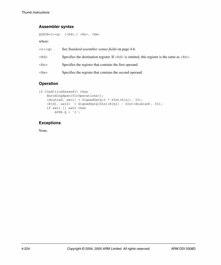
Thumb Instructions
Assembler syntax
QDSUB<c><q> {<Rd>,} <Rn>, <Rm>
where:
<c><q> See Standard assembler syntax fields on page 4-6.
<Rd> Specifies the destination register. If <Rd> is omitted, this register is the same as <Rn>.
<Rn> Specifies the register that contains the first operand.
<Rm> Specifies the register that contains the second operand.
Operation
if ConditionPassed() then EncodingSpecificOperations(); (doubled, sat1) = SignedSatQ(2 * SInt(R[n]), 32); (R[d], sat2) = SignedSatQ(SInt(R[m]) - SInt(doubled), 32); if sat1 || sat2 then APSR.Q = '1';
Exceptions
None.
4-224 Copyright © 2004, 2005 ARM Limited. All rights reserved. ARM DDI 0308D
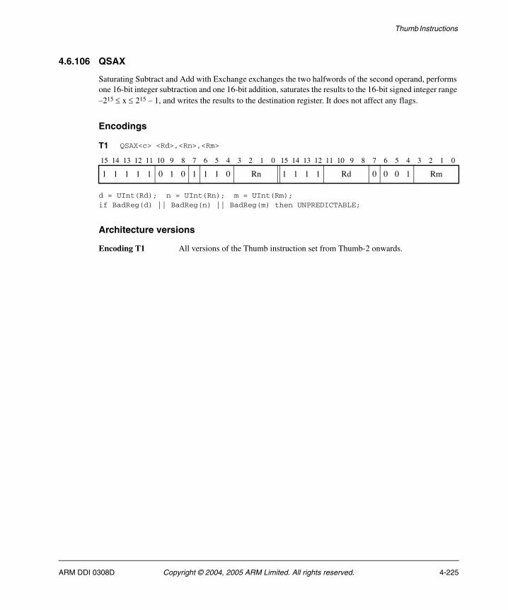
Thumb Instructions
4.6.106 QSAX
Saturating Subtract and Add with Exchange exchanges the two halfwords of the second operand, performs one 16-bit integer subtraction and one 16-bit addition, saturates the results to the 16-bit signed integer range –215 ≤ x ≤ 215 – 1, and writes the results to the destination register. It does not affect any flags.
Encodings
d = UInt(Rd); n = UInt(Rn); m = UInt(Rm);if BadReg(d) || BadReg(n) || BadReg(m) then UNPREDICTABLE;
Architecture versions
Encoding T1 All versions of the Thumb instruction set from Thumb-2 onwards.
T1 QSAX<c> <Rd>,<Rn>,<Rm>
15 14 13 12 11 10 9 8 7 6 5 4 3 2 1 0 15 14 13 12 11 10 9 8 7 6 5 4 3 2 1 0
1 1 1 1 1 0 1 0 1 1 1 0 Rn 1 1 1 1 Rd 0 0 0 1 Rm
ARM DDI 0308D Copyright © 2004, 2005 ARM Limited. All rights reserved. 4-225
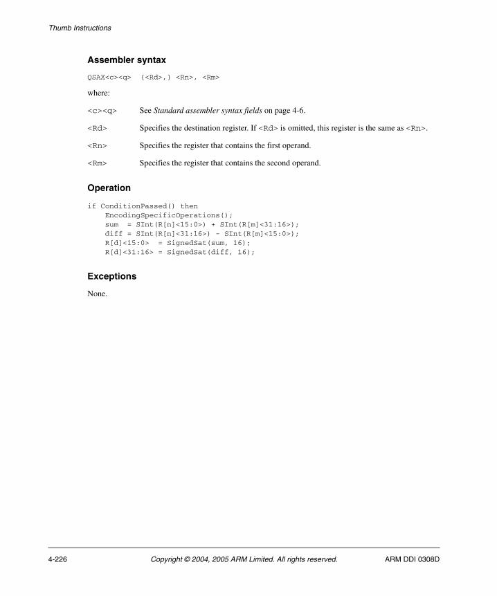
Thumb Instructions
Assembler syntax
QSAX<c><q> {<Rd>,} <Rn>, <Rm>
where:
<c><q> See Standard assembler syntax fields on page 4-6.
<Rd> Specifies the destination register. If <Rd> is omitted, this register is the same as <Rn>.
<Rn> Specifies the register that contains the first operand.
<Rm> Specifies the register that contains the second operand.
Operation
if ConditionPassed() then EncodingSpecificOperations(); sum = SInt(R[n]<15:0>) + SInt(R[m]<31:16>); diff = SInt(R[n]<31:16>) - SInt(R[m]<15:0>); R[d]<15:0> = SignedSat(sum, 16); R[d]<31:16> = SignedSat(diff, 16);
Exceptions
None.
4-226 Copyright © 2004, 2005 ARM Limited. All rights reserved. ARM DDI 0308D

Thumb Instructions
4.6.107 QSUB
Saturating Subtract subtracts one register value from another register value, saturates the result to the 32-bit signed integer range –231 ≤ x ≤ 231 – 1, and writes the result to the destination register. If saturation occurs, it sets the Q flag in the CPSR.
Encodings
d = UInt(Rd); n = UInt(Rn); m = UInt(Rm);if BadReg(d) || BadReg(n) || BadReg(m) then UNPREDICTABLE;
Architecture versions
Encoding T1 All versions of the Thumb instruction set from Thumb-2 onwards.
T1 QSUB<c> <Rd>,<Rn>,<Rm>
15 14 13 12 11 10 9 8 7 6 5 4 3 2 1 0 15 14 13 12 11 10 9 8 7 6 5 4 3 2 1 0
1 1 1 1 1 0 1 0 1 0 0 0 Rn 1 1 1 1 Rd 1 0 1 0 Rm
ARM DDI 0308D Copyright © 2004, 2005 ARM Limited. All rights reserved. 4-227
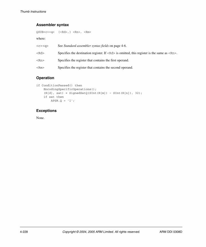
Thumb Instructions
Assembler syntax
QSUB<c><q> {<Rd>,} <Rn>, <Rm>
where:
<c><q> See Standard assembler syntax fields on page 4-6.
<Rd> Specifies the destination register. If <Rd> is omitted, this register is the same as <Rn>.
<Rn> Specifies the register that contains the first operand.
<Rm> Specifies the register that contains the second operand.
Operation
if ConditionPassed() then EncodingSpecificOperations(); (R[d], sat) = SignedSatQ(SInt(R[m]) - SInt(R[n]), 32); if sat then APSR.Q = '1';
Exceptions
None.
4-228 Copyright © 2004, 2005 ARM Limited. All rights reserved. ARM DDI 0308D
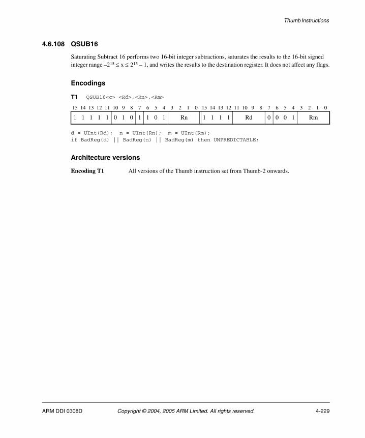
Thumb Instructions
4.6.108 QSUB16
Saturating Subtract 16 performs two 16-bit integer subtractions, saturates the results to the 16-bit signed integer range –215 ≤ x ≤ 215 – 1, and writes the results to the destination register. It does not affect any flags.
Encodings
d = UInt(Rd); n = UInt(Rn); m = UInt(Rm);if BadReg(d) || BadReg(n) || BadReg(m) then UNPREDICTABLE;
Architecture versions
Encoding T1 All versions of the Thumb instruction set from Thumb-2 onwards.
T1 QSUB16<c> <Rd>,<Rn>,<Rm>
15 14 13 12 11 10 9 8 7 6 5 4 3 2 1 0 15 14 13 12 11 10 9 8 7 6 5 4 3 2 1 0
1 1 1 1 1 0 1 0 1 1 0 1 Rn 1 1 1 1 Rd 0 0 0 1 Rm
ARM DDI 0308D Copyright © 2004, 2005 ARM Limited. All rights reserved. 4-229

Thumb Instructions
Assembler syntax
QSUB16<c><q> {<Rd>,} <Rn>, <Rm>
where:
<c><q> See Standard assembler syntax fields on page 4-6.
<Rd> Specifies the destination register. If <Rd> is omitted, this register is the same as <Rn>.
<Rn> Specifies the register that contains the first operand.
<Rm> Specifies the register that contains the second operand.
Operation
if ConditionPassed() then EncodingSpecificOperations(); diff1 = SInt(R[n]<15:0>) - SInt(R[m]<15:0>); diff2 = SInt(R[n]<31:16>) - SInt(R[m]<31:16>); R[d]<15:0> = SignedSat(diff1, 16); R[d]<31:16> = SignedSat(diff2, 16);
Exceptions
None.
4-230 Copyright © 2004, 2005 ARM Limited. All rights reserved. ARM DDI 0308D
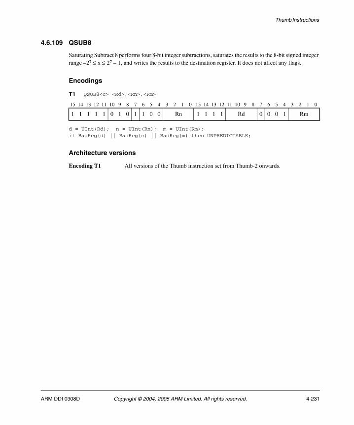
Thumb Instructions
4.6.109 QSUB8
Saturating Subtract 8 performs four 8-bit integer subtractions, saturates the results to the 8-bit signed integer range –27 ≤ x ≤ 27 – 1, and writes the results to the destination register. It does not affect any flags.
Encodings
d = UInt(Rd); n = UInt(Rn); m = UInt(Rm);if BadReg(d) || BadReg(n) || BadReg(m) then UNPREDICTABLE;
Architecture versions
Encoding T1 All versions of the Thumb instruction set from Thumb-2 onwards.
T1 QSUB8<c> <Rd>,<Rn>,<Rm>
15 14 13 12 11 10 9 8 7 6 5 4 3 2 1 0 15 14 13 12 11 10 9 8 7 6 5 4 3 2 1 0
1 1 1 1 1 0 1 0 1 1 0 0 Rn 1 1 1 1 Rd 0 0 0 1 Rm
ARM DDI 0308D Copyright © 2004, 2005 ARM Limited. All rights reserved. 4-231

Thumb Instructions
Assembler syntax
QSUB8<c><q> {<Rd>,} <Rn>, <Rm>
where:
<c><q> See Standard assembler syntax fields on page 4-6.
<Rd> Specifies the destination register. If <Rd> is omitted, this register is the same as <Rn>.
<Rn> Specifies the register that contains the first operand.
<Rm> Specifies the register that contains the second operand.
Operation
if ConditionPassed() then EncodingSpecificOperations(); diff1 = SInt(R[n]<7:0>) - SInt(R[m]<7:0>); diff2 = SInt(R[n]<15:8>) - SInt(R[m]<15:8>); diff3 = SInt(R[n]<23:16>) - SInt(R[m]<23:16>); diff4 = SInt(R[n]<31:24>) - SInt(R[m]<31:24>); R[d]<7:0> = SignedSat(diff1, 8); R[d]<15:8> = SignedSat(diff2, 8); R[d]<23:16> = SignedSat(diff3, 8); R[d]<31:24> = SignedSat(diff4, 8);
Exceptions
None.
4-232 Copyright © 2004, 2005 ARM Limited. All rights reserved. ARM DDI 0308D
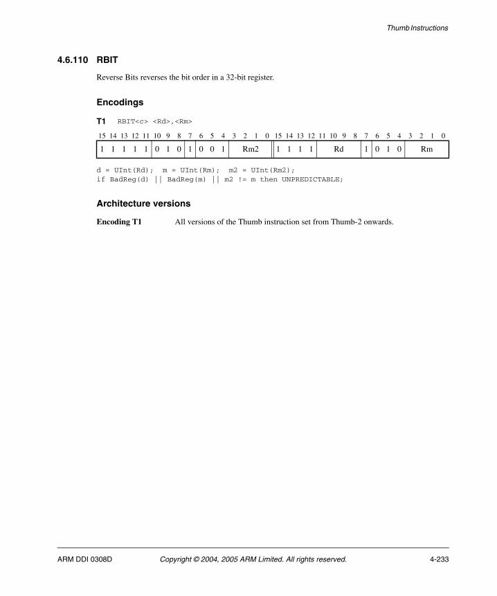
Thumb Instructions
4.6.110 RBIT
Reverse Bits reverses the bit order in a 32-bit register.
Encodings
d = UInt(Rd); m = UInt(Rm); m2 = UInt(Rm2);if BadReg(d) || BadReg(m) || m2 != m then UNPREDICTABLE;
Architecture versions
Encoding T1 All versions of the Thumb instruction set from Thumb-2 onwards.
T1 RBIT<c> <Rd>,<Rm>
15 14 13 12 11 10 9 8 7 6 5 4 3 2 1 0 15 14 13 12 11 10 9 8 7 6 5 4 3 2 1 0
1 1 1 1 1 0 1 0 1 0 0 1 Rm2 1 1 1 1 Rd 1 0 1 0 Rm
ARM DDI 0308D Copyright © 2004, 2005 ARM Limited. All rights reserved. 4-233

Thumb Instructions
Assembler syntax
RBIT<c><q> <Rd>, <Rm>
where:
<c><q> See Standard assembler syntax fields on page 4-6.
<Rd> Specifies the destination register.
<Rm> Specifies the register that contains the operand. Its number must be encoded twice in encoding T1, in both the Rm and Rm2 fields.
Operation
if ConditionPassed() then EncodingSpecificOperations(); bits(32) result; for i = 0 to 31 do result<31-i> = R[m]<i>; R[d] = result;
Exceptions
None.
4-234 Copyright © 2004, 2005 ARM Limited. All rights reserved. ARM DDI 0308D
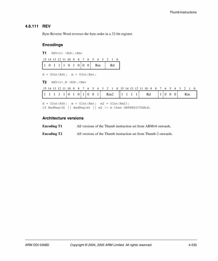
Thumb Instructions
4.6.111 REV
Byte-Reverse Word reverses the byte order in a 32-bit register.
Encodings
d = UInt(Rd); m = UInt(Rm);
d = UInt(Rd); m = UInt(Rm); m2 = UInt(Rm2);if BadReg(d) || BadReg(m) || m2 != m then UNPREDICTABLE;
Architecture versions
Encoding T1 All versions of the Thumb instruction set from ARMv6 onwards.
Encoding T2 All versions of the Thumb instruction set from Thumb-2 onwards.
T1 REV<c> <Rd>,<Rm>
15 14 13 12 11 10 9 8 7 6 5 4 3 2 1 0
1 0 1 1 1 0 1 0 0 0 Rm Rd
T2 REV<c>.W <Rd>,<Rm>
15 14 13 12 11 10 9 8 7 6 5 4 3 2 1 0 15 14 13 12 11 10 9 8 7 6 5 4 3 2 1 0
1 1 1 1 1 0 1 0 1 0 0 1 Rm2 1 1 1 1 Rd 1 0 0 0 Rm
ARM DDI 0308D Copyright © 2004, 2005 ARM Limited. All rights reserved. 4-235
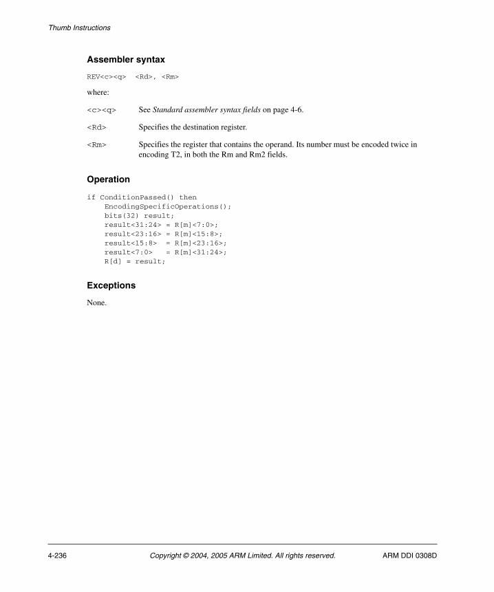
Thumb Instructions
Assembler syntax
REV<c><q> <Rd>, <Rm>
where:
<c><q> See Standard assembler syntax fields on page 4-6.
<Rd> Specifies the destination register.
<Rm> Specifies the register that contains the operand. Its number must be encoded twice in encoding T2, in both the Rm and Rm2 fields.
Operation
if ConditionPassed() then EncodingSpecificOperations(); bits(32) result; result<31:24> = R[m]<7:0>; result<23:16> = R[m]<15:8>; result<15:8> = R[m]<23:16>; result<7:0> = R[m]<31:24>; R[d] = result;
Exceptions
None.
4-236 Copyright © 2004, 2005 ARM Limited. All rights reserved. ARM DDI 0308D
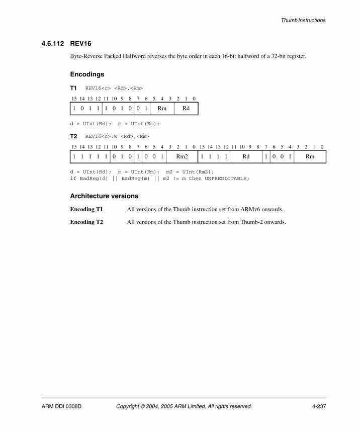
Thumb Instructions
4.6.112 REV16
Byte-Reverse Packed Halfword reverses the byte order in each 16-bit halfword of a 32-bit register.
Encodings
d = UInt(Rd); m = UInt(Rm);
d = UInt(Rd); m = UInt(Rm); m2 = UInt(Rm2);if BadReg(d) || BadReg(m) || m2 != m then UNPREDICTABLE;
Architecture versions
Encoding T1 All versions of the Thumb instruction set from ARMv6 onwards.
Encoding T2 All versions of the Thumb instruction set from Thumb-2 onwards.
T1 REV16<c> <Rd>,<Rm>
15 14 13 12 11 10 9 8 7 6 5 4 3 2 1 0
1 0 1 1 1 0 1 0 0 1 Rm Rd
T2 REV16<c>.W <Rd>,<Rm>
15 14 13 12 11 10 9 8 7 6 5 4 3 2 1 0 15 14 13 12 11 10 9 8 7 6 5 4 3 2 1 0
1 1 1 1 1 0 1 0 1 0 0 1 Rm2 1 1 1 1 Rd 1 0 0 1 Rm
ARM DDI 0308D Copyright © 2004, 2005 ARM Limited. All rights reserved. 4-237

Thumb Instructions
Assembler syntax
REV16<c><q> <Rd>, <Rm>
where:
<c><q> See Standard assembler syntax fields on page 4-6.
<Rd> Specifies the destination register.
<Rm> Specifies the register that contains the operand. Its number must be encoded twice in encoding T2, in both the Rm and Rm2 fields.
Operation
if ConditionPassed() then EncodingSpecificOperations(); bits(32) result; result<31:24> = R[m]<23:16>; result<23:16> = R[m]<31:24>; result<15:8> = R[m]<7:0>; result<7:0> = R[m]<15:8>; R[d] = result;
Exceptions
None.
4-238 Copyright © 2004, 2005 ARM Limited. All rights reserved. ARM DDI 0308D
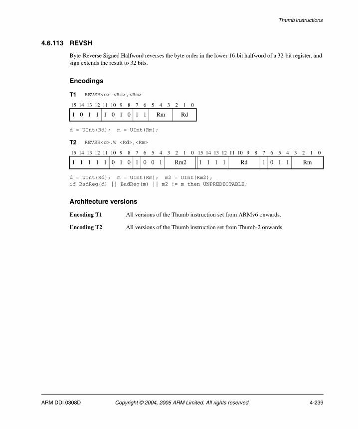
Thumb Instructions
4.6.113 REVSH
Byte-Reverse Signed Halfword reverses the byte order in the lower 16-bit halfword of a 32-bit register, and sign extends the result to 32 bits.
Encodings
d = UInt(Rd); m = UInt(Rm);
d = UInt(Rd); m = UInt(Rm); m2 = UInt(Rm2);if BadReg(d) || BadReg(m) || m2 != m then UNPREDICTABLE;
Architecture versions
Encoding T1 All versions of the Thumb instruction set from ARMv6 onwards.
Encoding T2 All versions of the Thumb instruction set from Thumb-2 onwards.
T1 REVSH<c> <Rd>,<Rm>
15 14 13 12 11 10 9 8 7 6 5 4 3 2 1 0
1 0 1 1 1 0 1 0 1 1 Rm Rd
T2 REVSH<c>.W <Rd>,<Rm>
15 14 13 12 11 10 9 8 7 6 5 4 3 2 1 0 15 14 13 12 11 10 9 8 7 6 5 4 3 2 1 0
1 1 1 1 1 0 1 0 1 0 0 1 Rm2 1 1 1 1 Rd 1 0 1 1 Rm
ARM DDI 0308D Copyright © 2004, 2005 ARM Limited. All rights reserved. 4-239
Thumb Instructions
Assembler syntax
REVSH<c><q> <Rd>, <Rm>
where:
<c><q> See Standard assembler syntax fields on page 4-6.
<Rd> Specifies the destination register.
<Rm> Specifies the register that contains the operand. Its number must be encoded twice in encoding T2, in both the Rm and Rm2 fields.
Operation
if ConditionPassed() then EncodingSpecificOperations(); bits(32) result; result<31:8> = SignExtend(R[m]<7:0>, 24); result<7:0> = R[m]<15:8>; R[d] = result;
Exceptions
None.
4-240 Copyright © 2004, 2005 ARM Limited. All rights reserved. ARM DDI 0308D
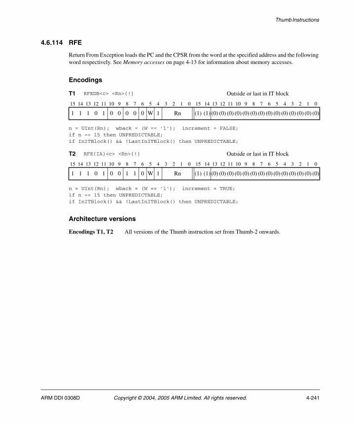
Thumb Instructions
4.6.114 RFE
Return From Exception loads the PC and the CPSR from the word at the specified address and the following word respectively. See Memory accesses on page 4-13 for information about memory accesses.
Encodings
n = UInt(Rn); wback = (W == '1'); increment = FALSE;if n == 15 then UNPREDICTABLE;if InITBlock() && !LastInITBlock() then UNPREDICTABLE;
n = UInt(Rn); wback = (W == '1'); increment = TRUE;if n == 15 then UNPREDICTABLE;if InITBlock() && !LastInITBlock() then UNPREDICTABLE;
Architecture versions
Encodings T1, T2 All versions of the Thumb instruction set from Thumb-2 onwards.
T1 RFEDB<c> <Rn>{!} Outside or last in IT block
15 14 13 12 11 10 9 8 7 6 5 4 3 2 1 0 15 14 13 12 11 10 9 8 7 6 5 4 3 2 1 0
1 1 1 0 1 0 0 0 0 0 W 1 Rn (1) (1) (0) (0) (0) (0) (0) (0) (0) (0) (0) (0) (0) (0) (0) (0)
T2 RFE{IA}<c> <Rn>{!} Outside or last in IT block
15 14 13 12 11 10 9 8 7 6 5 4 3 2 1 0 15 14 13 12 11 10 9 8 7 6 5 4 3 2 1 0
1 1 1 0 1 0 0 1 1 0 W 1 Rn (1) (1) (0) (0) (0) (0) (0) (0) (0) (0) (0) (0) (0) (0) (0) (0)
ARM DDI 0308D Copyright © 2004, 2005 ARM Limited. All rights reserved. 4-241
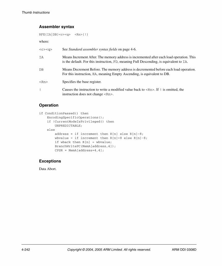
Thumb Instructions
Assembler syntax
RFE{IA|DB}<c><q> <Rn>{!}
where:
<c><q> See Standard assembler syntax fields on page 4-6.
IA Means Increment After. The memory address is incremented after each load operation. This is the default. For this instruction, FD, meaning Full Descending, is equivalent to IA.
DB Means Decrement Before. The memory address is decremented before each load operation. For this instruction, EA, meaning Empty Ascending, is equivalent to DB.
<Rn> Specifies the base register.
! Causes the instruction to write a modified value back to <Rn>. If ! is omitted, the instruction does not change <Rn>.
Operation
if ConditionPassed() then EncodingSpecificOperations(); if !CurrentModeIsPrivileged() then UNPREDICTABLE; else address = if increment then R[n] else R[n]-8; wbvalue = if increment then R[n]+8 else R[n]-8; if wback then R[n] = wbvalue; BranchWritePC(MemA[address,4]); CPSR = MemA[address+4,4];
Exceptions
Data Abort.
4-242 Copyright © 2004, 2005 ARM Limited. All rights reserved. ARM DDI 0308D
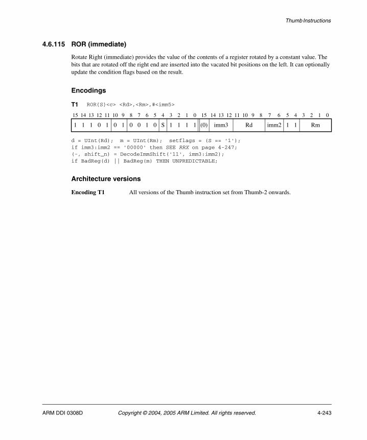
Thumb Instructions
4.6.115 ROR (immediate)
Rotate Right (immediate) provides the value of the contents of a register rotated by a constant value. The bits that are rotated off the right end are inserted into the vacated bit positions on the left. It can optionally update the condition flags based on the result.
Encodings
d = UInt(Rd); m = UInt(Rm); setflags = (S == '1');if imm3:imm2 == '00000' then SEE RRX on page 4-247;(-, shift_n) = DecodeImmShift('11', imm3:imm2);if BadReg(d) || BadReg(m) THEN UNPREDICTABLE;
Architecture versions
Encoding T1 All versions of the Thumb instruction set from Thumb-2 onwards.
T1 ROR{S}<c> <Rd>,<Rm>,#<imm5>
15 14 13 12 11 10 9 8 7 6 5 4 3 2 1 0 15 14 13 12 11 10 9 8 7 6 5 4 3 2 1 0
1 1 1 0 1 0 1 0 0 1 0 S 1 1 1 1 (0) imm3 Rd imm2 1 1 Rm
ARM DDI 0308D Copyright © 2004, 2005 ARM Limited. All rights reserved. 4-243
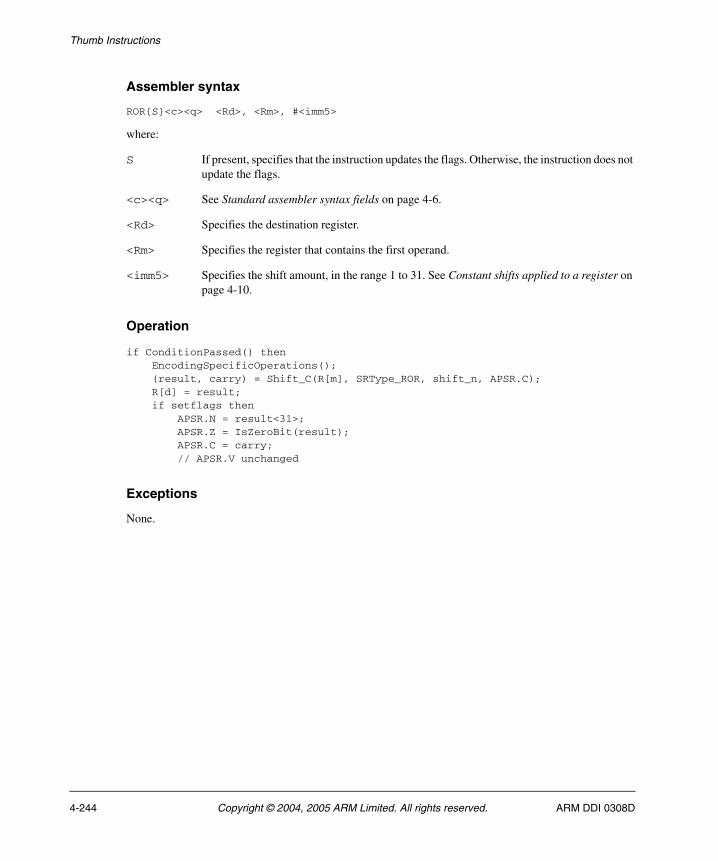
Thumb Instructions
Assembler syntax
ROR{S}<c><q> <Rd>, <Rm>, #<imm5>
where:
S If present, specifies that the instruction updates the flags. Otherwise, the instruction does not update the flags.
<c><q> See Standard assembler syntax fields on page 4-6.
<Rd> Specifies the destination register.
<Rm> Specifies the register that contains the first operand.
<imm5> Specifies the shift amount, in the range 1 to 31. See Constant shifts applied to a register on page 4-10.
Operation
if ConditionPassed() then EncodingSpecificOperations(); (result, carry) = Shift_C(R[m], SRType_ROR, shift_n, APSR.C); R[d] = result; if setflags then APSR.N = result<31>; APSR.Z = IsZeroBit(result); APSR.C = carry; // APSR.V unchanged
Exceptions
None.
4-244 Copyright © 2004, 2005 ARM Limited. All rights reserved. ARM DDI 0308D

Thumb Instructions
4.6.116 ROR (register)
Rotate Right (register) provides the value of the contents of a register rotated by a variable number of bits. The bits that are rotated off the right end are inserted into the vacated bit positions on the left. The variable number of bits is read from the bottom byte of a register. It can optionally update the condition flags based on the result.
Encodings
d = UInt(Rdn); n = UInt(Rdn); m = UInt(Rm); setflags = !InITBlock();
d = UInt(Rd); n = UInt(Rn); m = UInt(Rm); setflags = (S == '1');if BadReg(d) || BadReg(n) || BadReg(m) then UNPREDICTABLE;
Architecture versions
Encoding T1 All versions of the Thumb instruction set
Encoding T2 All versions of the Thumb instruction set from Thumb-2 onwards.
T1 RORS <Rdn>,<Rm> Outside IT block.ROR<c> <Rdn>,<Rm> Inside IT block.
15 14 13 12 11 10 9 8 7 6 5 4 3 2 1 0
0 1 0 0 0 0 0 1 1 1 Rm Rdn
T2 ROR{S}<c>.W <Rd>,<Rn>,<Rm>
15 14 13 12 11 10 9 8 7 6 5 4 3 2 1 0 15 14 13 12 11 10 9 8 7 6 5 4 3 2 1 0
1 1 1 1 1 0 1 0 0 1 1 S Rn 1 1 1 1 Rd 0 0 0 0 Rm
ARM DDI 0308D Copyright © 2004, 2005 ARM Limited. All rights reserved. 4-245
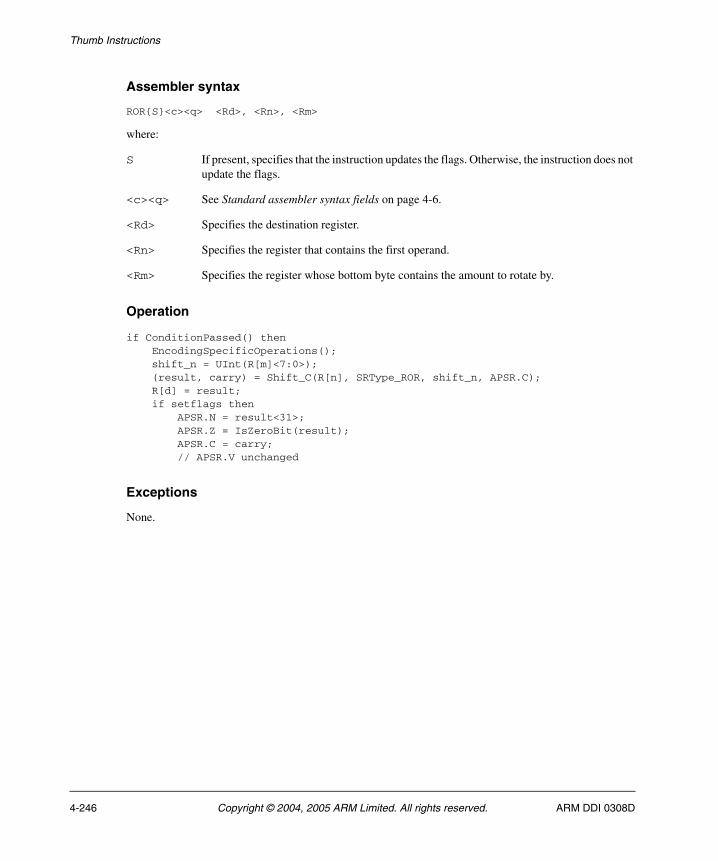
Thumb Instructions
Assembler syntax
ROR{S}<c><q> <Rd>, <Rn>, <Rm>
where:
S If present, specifies that the instruction updates the flags. Otherwise, the instruction does not update the flags.
<c><q> See Standard assembler syntax fields on page 4-6.
<Rd> Specifies the destination register.
<Rn> Specifies the register that contains the first operand.
<Rm> Specifies the register whose bottom byte contains the amount to rotate by.
Operation
if ConditionPassed() then EncodingSpecificOperations(); shift_n = UInt(R[m]<7:0>); (result, carry) = Shift_C(R[n], SRType_ROR, shift_n, APSR.C); R[d] = result; if setflags then APSR.N = result<31>; APSR.Z = IsZeroBit(result); APSR.C = carry; // APSR.V unchanged
Exceptions
None.
4-246 Copyright © 2004, 2005 ARM Limited. All rights reserved. ARM DDI 0308D

Thumb Instructions
4.6.117 RRX
Rotate Right with Extend provides the value of the contents of a register shifted right by one place, with the carry flag shifted into bit[31].
RRX can optionally update the condition flags based on the result. In that case, bit[0] is shifted into the carry flag.
Encodings
d = UInt(Rd); m = UInt(Rm); setflags = (S == '1');if BadReg(d) || BadReg(m) THEN UNPREDICTABLE;
Architecture versions
Encoding T1 All versions of the Thumb instruction set from Thumb-2 onwards.
T1 RRX{S}<c> <Rd>,<Rm>
15 14 13 12 11 10 9 8 7 6 5 4 3 2 1 0 15 14 13 12 11 10 9 8 7 6 5 4 3 2 1 0
1 1 1 0 1 0 1 0 0 1 0 S 1 1 1 1 (0) 0 0 0 Rd 0 0 1 1 Rm
ARM DDI 0308D Copyright © 2004, 2005 ARM Limited. All rights reserved. 4-247
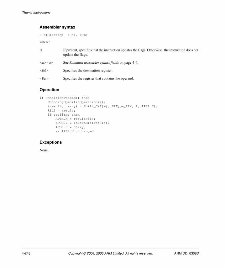
Thumb Instructions
Assembler syntax
RRX{S}<c><q> <Rd>, <Rm>
where:
S If present, specifies that the instruction updates the flags. Otherwise, the instruction does not update the flags.
<c><q> See Standard assembler syntax fields on page 4-6.
<Rd> Specifies the destination register.
<Rm> Specifies the register that contains the operand.
Operation
if ConditionPassed() then EncodingSpecificOperations(); (result, carry) = Shift_C(R[m], SRType_RRX, 1, APSR.C); R[d] = result; if setflags then APSR.N = result<31>; APSR.Z = IsZeroBit(result); APSR.C = carry; // APSR.V unchanged
Exceptions
None.
4-248 Copyright © 2004, 2005 ARM Limited. All rights reserved. ARM DDI 0308D
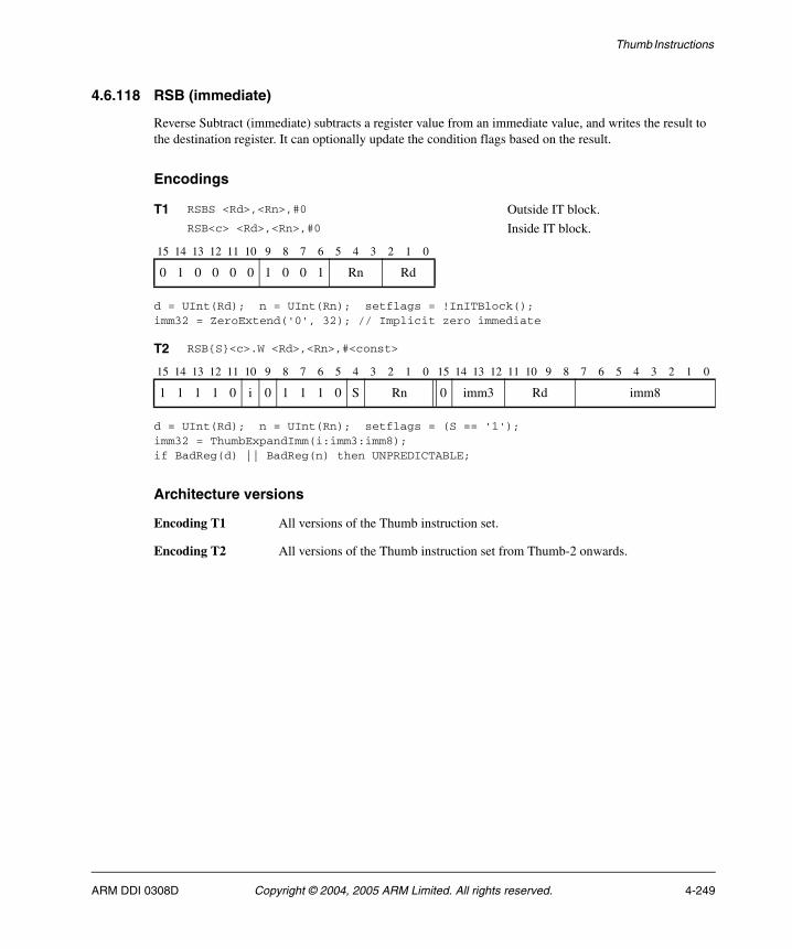
Thumb Instructions
4.6.118 RSB (immediate)
Reverse Subtract (immediate) subtracts a register value from an immediate value, and writes the result to the destination register. It can optionally update the condition flags based on the result.
Encodings
d = UInt(Rd); n = UInt(Rn); setflags = !InITBlock();imm32 = ZeroExtend('0', 32); // Implicit zero immediate
d = UInt(Rd); n = UInt(Rn); setflags = (S == '1');imm32 = ThumbExpandImm(i:imm3:imm8);if BadReg(d) || BadReg(n) then UNPREDICTABLE;
Architecture versions
Encoding T1 All versions of the Thumb instruction set.
Encoding T2 All versions of the Thumb instruction set from Thumb-2 onwards.
T1 RSBS <Rd>,<Rn>,#0 Outside IT block.RSB<c> <Rd>,<Rn>,#0 Inside IT block.
15 14 13 12 11 10 9 8 7 6 5 4 3 2 1 0
0 1 0 0 0 0 1 0 0 1 Rn Rd
T2 RSB{S}<c>.W <Rd>,<Rn>,#<const>
15 14 13 12 11 10 9 8 7 6 5 4 3 2 1 0 15 14 13 12 11 10 9 8 7 6 5 4 3 2 1 0
1 1 1 1 0 i 0 1 1 1 0 S Rn 0 imm3 Rd imm8
ARM DDI 0308D Copyright © 2004, 2005 ARM Limited. All rights reserved. 4-249
Thumb Instructions
Assembler syntax
RSB{S}<c><q> {<Rd>,} <Rn>, #<const>
where:
S If present, specifies that the instruction updates the flags. Otherwise, the instruction does not update the flags.
<c><q> See Standard assembler syntax fields on page 4-6.
<Rd> Specifies the destination register. If <Rd> is omitted, this register is the same as <Rn>.
<Rn> Specifies the register that contains the first operand.
<const> Specifies the immediate value to be added to the value obtained from <Rn>. The only allowed value for encoding T1 is 0. See Immediate constants on page 4-8 for the range of allowed values for encoding T2.
The pre-UAL syntax RSB<c>S is equivalent to RSBS<c>.
Operation
if ConditionPassed() then EncodingSpecificOperations(); (result, carry, overflow) = AddWithCarry(NOT(R[n]), imm32, '1'); R[d] = result; if setflags then APSR.N = result<31>; APSR.Z = IsZeroBit(result); APSR.C = carry; APSR.V = overflow;
Exceptions
None.
4-250 Copyright © 2004, 2005 ARM Limited. All rights reserved. ARM DDI 0308D
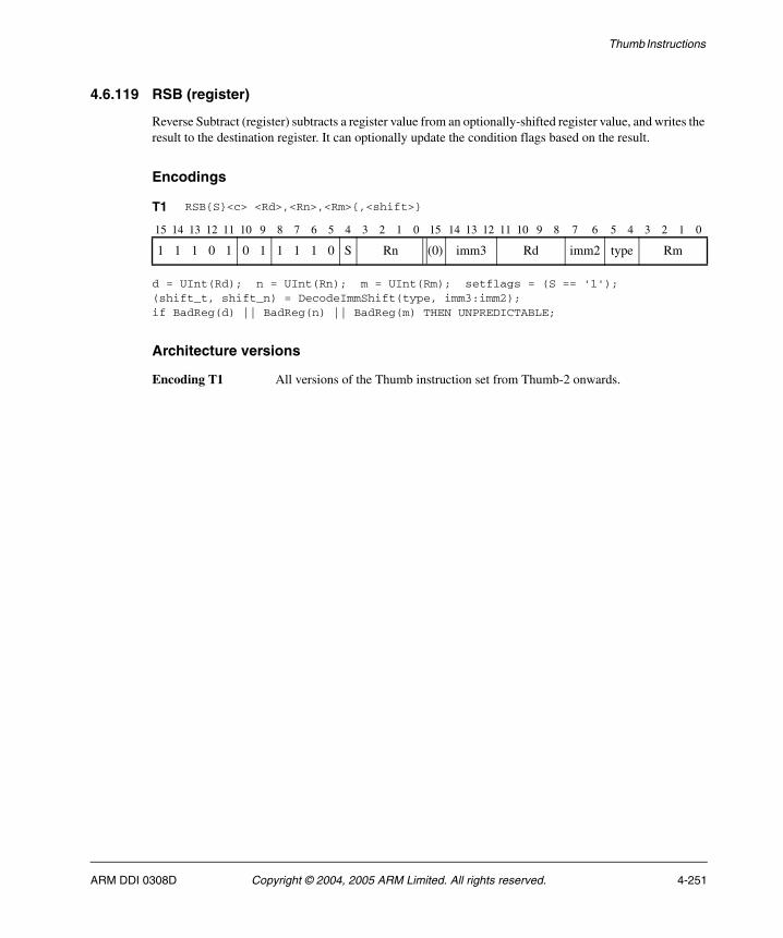
Thumb Instructions
4.6.119 RSB (register)
Reverse Subtract (register) subtracts a register value from an optionally-shifted register value, and writes the result to the destination register. It can optionally update the condition flags based on the result.
Encodings
d = UInt(Rd); n = UInt(Rn); m = UInt(Rm); setflags = (S == '1');(shift_t, shift_n) = DecodeImmShift(type, imm3:imm2);if BadReg(d) || BadReg(n) || BadReg(m) THEN UNPREDICTABLE;
Architecture versions
Encoding T1 All versions of the Thumb instruction set from Thumb-2 onwards.
T1 RSB{S}<c> <Rd>,<Rn>,<Rm>{,<shift>}
15 14 13 12 11 10 9 8 7 6 5 4 3 2 1 0 15 14 13 12 11 10 9 8 7 6 5 4 3 2 1 0
1 1 1 0 1 0 1 1 1 1 0 S Rn (0) imm3 Rd imm2 type Rm
ARM DDI 0308D Copyright © 2004, 2005 ARM Limited. All rights reserved. 4-251
Thumb Instructions
Assembler syntax
RSB{S}<c><q> {<Rd>,} <Rn>, <Rm> {,<shift>}
where:
S If present, specifies that the instruction updates the flags. Otherwise, the instruction does not update the flags.
<c><q> See Standard assembler syntax fields on page 4-6.
<Rd> Specifies the destination register. If <Rd> is omitted, this register is the same as <Rn>.
<Rn> Specifies the register that contains the first operand.
<Rm> Specifies the register that is optionally shifted and used as the second operand.
<shift> Specifies the shift to apply to the value read from <Rm>. If <shift> is omitted, no shift is applied. The possible shifts and how they are encoded are described in Constant shifts applied to a register on page 4-10.
The pre-UAL syntax RSB<c>S is equivalent to RSBS<c>.
Operation
if ConditionPassed() then EncodingSpecificOperations(); shifted = Shift(R[m], shift_t, shift_n, APSR.C); (result, carry, overflow) = AddWithCarry(NOT(R[n]), shifted, '1'); R[d] = result; if setflags then APSR.N = result<31>; APSR.Z = IsZeroBit(result); APSR.C = carry; APSR.V = overflow;
Exceptions
None.
4-252 Copyright © 2004, 2005 ARM Limited. All rights reserved. ARM DDI 0308D

Thumb Instructions
4.6.120 SADD16
Signed Add 16 performs two 16-bit signed integer additions, and writes the results to the destination register. It sets the GE bits in the APSR according to the results of the additions.
Encodings
d = UInt(Rd); n = UInt(Rn); m = UInt(Rm);if BadReg(d) || BadReg(n) || BadReg(m) then UNPREDICTABLE;
Architecture versions
Encoding T1 All versions of the Thumb instruction set from Thumb-2 onwards.
T1 SADD16<c> <Rd>,<Rn>,<Rm>
15 14 13 12 11 10 9 8 7 6 5 4 3 2 1 0 15 14 13 12 11 10 9 8 7 6 5 4 3 2 1 0
1 1 1 1 1 0 1 0 1 0 0 1 Rn 1 1 1 1 Rd 0 0 0 0 Rm
ARM DDI 0308D Copyright © 2004, 2005 ARM Limited. All rights reserved. 4-253

Thumb Instructions
Assembler syntax
SADD16<c><q> {<Rd>,} <Rn>, <Rm>
where:
<c><q> See Standard assembler syntax fields on page 4-6.
<Rd> Specifies the destination register. If <Rd> is omitted, this register is the same as <Rn>.
<Rn> Specifies the register that contains the first operand.
<Rm> Specifies the register that contains the second operand.
Operation
if ConditionPassed() then EncodingSpecificOperations(); sum1 = SInt(R[n]<15:0>) + SInt(R[m]<15:0>); sum2 = SInt(R[n]<31:16>) + SInt(R[m]<31:16>); R[d]<15:0> = sum1<15:0>; R[d]<31:16> = sum2<15:0>; APSR.GE<1:0> = if sum1 >= 0 then '11' else '00'; APSR.GE<3:2> = if sum2 >= 0 then '11' else '00';
Exceptions
None.
4-254 Copyright © 2004, 2005 ARM Limited. All rights reserved. ARM DDI 0308D
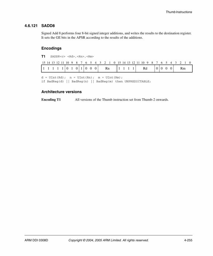
Thumb Instructions
4.6.121 SADD8
Signed Add 8 performs four 8-bit signed integer additions, and writes the results to the destination register. It sets the GE bits in the APSR according to the results of the additions.
Encodings
d = UInt(Rd); n = UInt(Rn); m = UInt(Rm);if BadReg(d) || BadReg(n) || BadReg(m) then UNPREDICTABLE;
Architecture versions
Encoding T1 All versions of the Thumb instruction set from Thumb-2 onwards.
T1 SADD8<c> <Rd>,<Rn>,<Rm>
15 14 13 12 11 10 9 8 7 6 5 4 3 2 1 0 15 14 13 12 11 10 9 8 7 6 5 4 3 2 1 0
1 1 1 1 1 0 1 0 1 0 0 0 Rn 1 1 1 1 Rd 0 0 0 0 Rm
ARM DDI 0308D Copyright © 2004, 2005 ARM Limited. All rights reserved. 4-255

Thumb Instructions
Assembler syntax
SADD8<c><q> {<Rd>,} <Rn>, <Rm>
where:
<c><q> See Standard assembler syntax fields on page 4-6.
<Rd> Specifies the destination register. If <Rd> is omitted, this register is the same as <Rn>.
<Rn> Specifies the register that contains the first operand.
<Rm> Specifies the register that contains the second operand.
Operation
if ConditionPassed() then EncodingSpecificOperations(); sum1 = SInt(R[n]<7:0>) + SInt(R[m]<7:0>); sum2 = SInt(R[n]<15:8>) + SInt(R[m]<15:8>); sum3 = SInt(R[n]<23:16>) + SInt(R[m]<23:16>); sum4 = SInt(R[n]<31:24>) + SInt(R[m]<31:24>); R[d]<7:0> = sum1<7:0>; R[d]<15:8> = sum2<7:0>; R[d]<23:16> = sum3<7:0>; R[d]<31:24> = sum4<7:0>; APSR.GE<0> = if sum1 >= 0 then '1' else '0'; APSR.GE<1> = if sum2 >= 0 then '1' else '0'; APSR.GE<2> = if sum3 >= 0 then '1' else '0'; APSR.GE<3> = if sum4 >= 0 then '1' else '0';
Exceptions
None.
4-256 Copyright © 2004, 2005 ARM Limited. All rights reserved. ARM DDI 0308D

Thumb Instructions
4.6.122 SASX
Signed Add and Subtract with Exchange exchanges the two halfwords of the second operand, performs one 16-bit integer addition and one 16-bit subtraction, and writes the results to the destination register. It sets the GE bits in the APSR according to the results.
Encodings
d = UInt(Rd); n = UInt(Rn); m = UInt(Rm);if BadReg(d) || BadReg(n) || BadReg(m) then UNPREDICTABLE;
Architecture versions
Encoding T1 All versions of the Thumb instruction set from Thumb-2 onwards.
T1 SASX<c> <Rd>,<Rn>,<Rm>
15 14 13 12 11 10 9 8 7 6 5 4 3 2 1 0 15 14 13 12 11 10 9 8 7 6 5 4 3 2 1 0
1 1 1 1 1 0 1 0 1 0 1 0 Rn 1 1 1 1 Rd 0 0 0 0 Rm
ARM DDI 0308D Copyright © 2004, 2005 ARM Limited. All rights reserved. 4-257

Thumb Instructions
Assembler syntax
SASX<c><q> {<Rd>,} <Rn>, <Rm>
where:
<c><q> See Standard assembler syntax fields on page 4-6.
<Rd> Specifies the destination register. If <Rd> is omitted, this register is the same as <Rn>.
<Rn> Specifies the register that contains the first operand.
<Rm> Specifies the register that contains the second operand.
Operation
if ConditionPassed() then EncodingSpecificOperations(); diff = SInt(R[n]<15:0>) - SInt(R[m]<31:16>); sum = SInt(R[n]<31:16>) + SInt(R[m]<15:0>); R[d]<15:0> = diff<15:0>; R[d]<31:16> = sum<15:0>; APSR.GE<1:0> = if diff >= 0 then '11' else '00'; APSR.GE<3:2> = if sum >= 0 then '11' else '00';
Exceptions
None.
4-258 Copyright © 2004, 2005 ARM Limited. All rights reserved. ARM DDI 0308D
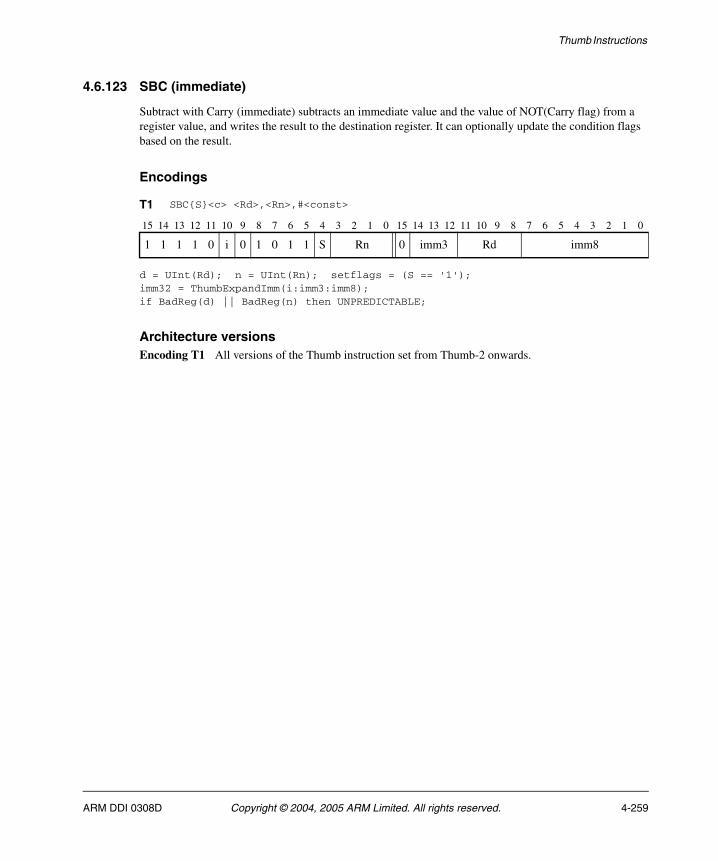
Thumb Instructions
4.6.123 SBC (immediate)
Subtract with Carry (immediate) subtracts an immediate value and the value of NOT(Carry flag) from a register value, and writes the result to the destination register. It can optionally update the condition flags based on the result.
Encodings
d = UInt(Rd); n = UInt(Rn); setflags = (S == '1');imm32 = ThumbExpandImm(i:imm3:imm8);if BadReg(d) || BadReg(n) then UNPREDICTABLE;
Architecture versionsEncoding T1 All versions of the Thumb instruction set from Thumb-2 onwards.
T1 SBC{S}<c> <Rd>,<Rn>,#<const>
15 14 13 12 11 10 9 8 7 6 5 4 3 2 1 0 15 14 13 12 11 10 9 8 7 6 5 4 3 2 1 0
1 1 1 1 0 i 0 1 0 1 1 S Rn 0 imm3 Rd imm8
ARM DDI 0308D Copyright © 2004, 2005 ARM Limited. All rights reserved. 4-259
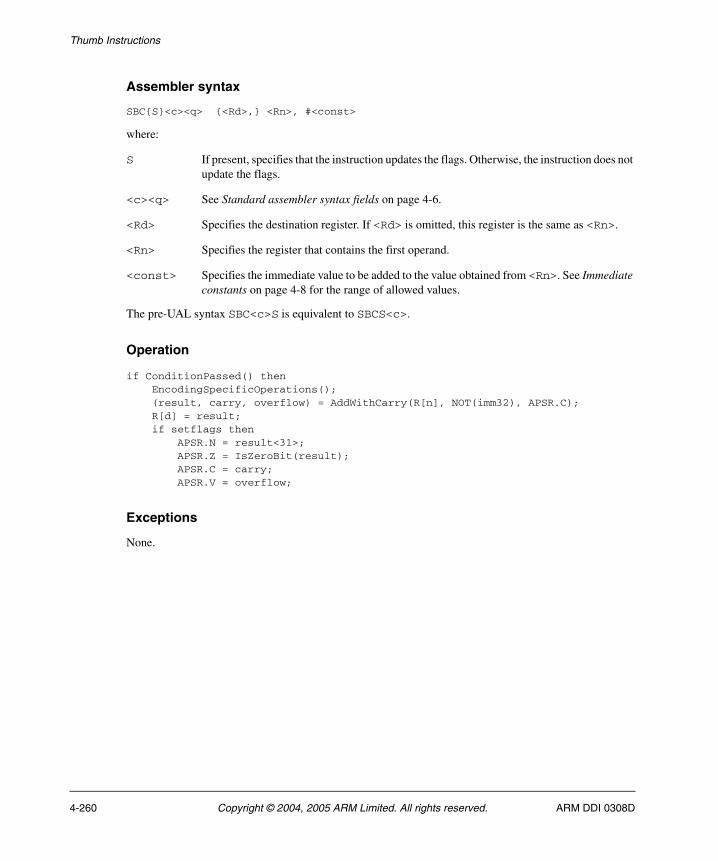
Thumb Instructions
Assembler syntax
SBC{S}<c><q> {<Rd>,} <Rn>, #<const>
where:
S If present, specifies that the instruction updates the flags. Otherwise, the instruction does not update the flags.
<c><q> See Standard assembler syntax fields on page 4-6.
<Rd> Specifies the destination register. If <Rd> is omitted, this register is the same as <Rn>.
<Rn> Specifies the register that contains the first operand.
<const> Specifies the immediate value to be added to the value obtained from <Rn>. See Immediate constants on page 4-8 for the range of allowed values.
The pre-UAL syntax SBC<c>S is equivalent to SBCS<c>.
Operation
if ConditionPassed() then EncodingSpecificOperations(); (result, carry, overflow) = AddWithCarry(R[n], NOT(imm32), APSR.C); R[d] = result; if setflags then APSR.N = result<31>; APSR.Z = IsZeroBit(result); APSR.C = carry; APSR.V = overflow;
Exceptions
None.
4-260 Copyright © 2004, 2005 ARM Limited. All rights reserved. ARM DDI 0308D
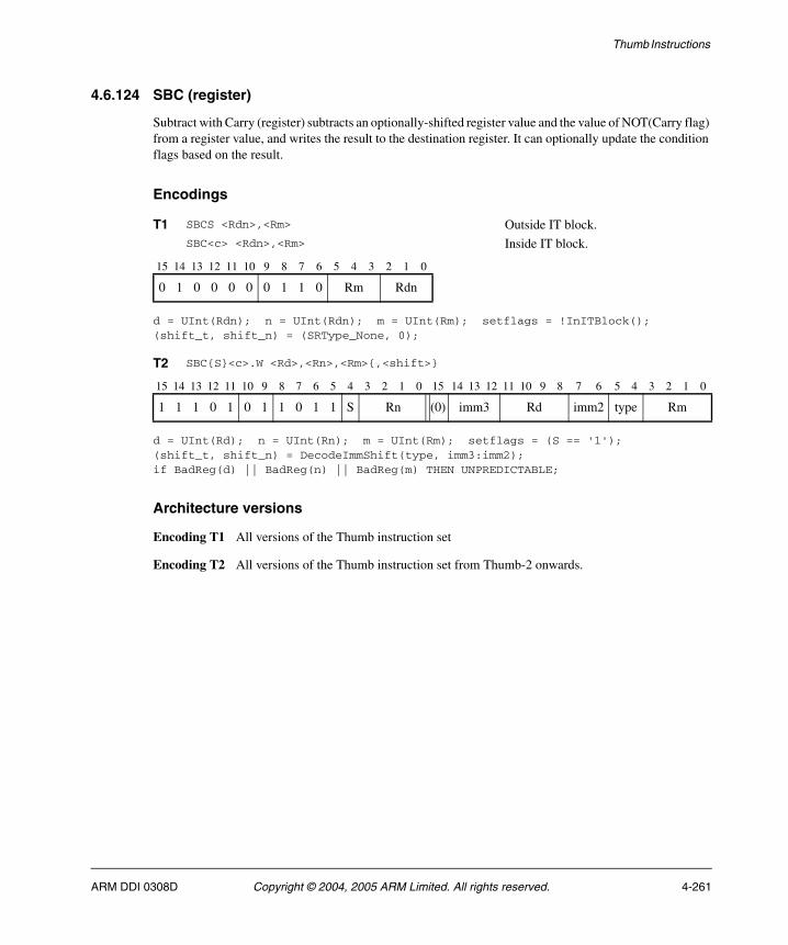
Thumb Instructions
4.6.124 SBC (register)
Subtract with Carry (register) subtracts an optionally-shifted register value and the value of NOT(Carry flag) from a register value, and writes the result to the destination register. It can optionally update the condition flags based on the result.
Encodings
d = UInt(Rdn); n = UInt(Rdn); m = UInt(Rm); setflags = !InITBlock();(shift_t, shift_n) = (SRType_None, 0);
d = UInt(Rd); n = UInt(Rn); m = UInt(Rm); setflags = (S == '1');(shift_t, shift_n) = DecodeImmShift(type, imm3:imm2);if BadReg(d) || BadReg(n) || BadReg(m) THEN UNPREDICTABLE;
Architecture versions
Encoding T1 All versions of the Thumb instruction set
Encoding T2 All versions of the Thumb instruction set from Thumb-2 onwards.
T1 SBCS <Rdn>,<Rm> Outside IT block.SBC<c> <Rdn>,<Rm> Inside IT block.
15 14 13 12 11 10 9 8 7 6 5 4 3 2 1 0
0 1 0 0 0 0 0 1 1 0 Rm Rdn
T2 SBC{S}<c>.W <Rd>,<Rn>,<Rm>{,<shift>}
15 14 13 12 11 10 9 8 7 6 5 4 3 2 1 0 15 14 13 12 11 10 9 8 7 6 5 4 3 2 1 0
1 1 1 0 1 0 1 1 0 1 1 S Rn (0) imm3 Rd imm2 type Rm
ARM DDI 0308D Copyright © 2004, 2005 ARM Limited. All rights reserved. 4-261
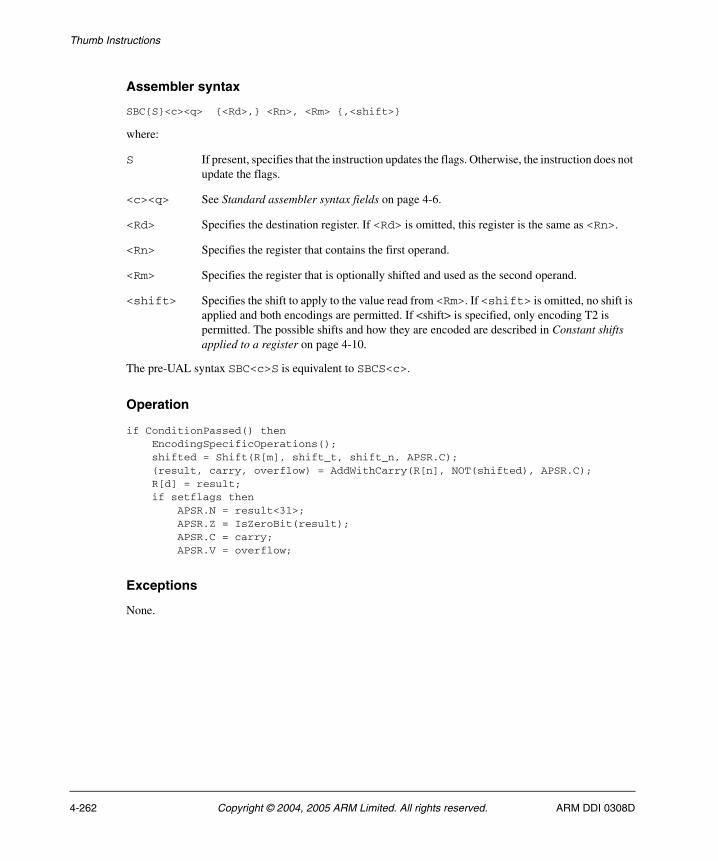
Thumb Instructions
Assembler syntax
SBC{S}<c><q> {<Rd>,} <Rn>, <Rm> {,<shift>}
where:
S If present, specifies that the instruction updates the flags. Otherwise, the instruction does not update the flags.
<c><q> See Standard assembler syntax fields on page 4-6.
<Rd> Specifies the destination register. If <Rd> is omitted, this register is the same as <Rn>.
<Rn> Specifies the register that contains the first operand.
<Rm> Specifies the register that is optionally shifted and used as the second operand.
<shift> Specifies the shift to apply to the value read from <Rm>. If <shift> is omitted, no shift is applied and both encodings are permitted. If <shift> is specified, only encoding T2 is permitted. The possible shifts and how they are encoded are described in Constant shifts applied to a register on page 4-10.
The pre-UAL syntax SBC<c>S is equivalent to SBCS<c>.
Operation
if ConditionPassed() then EncodingSpecificOperations(); shifted = Shift(R[m], shift_t, shift_n, APSR.C); (result, carry, overflow) = AddWithCarry(R[n], NOT(shifted), APSR.C); R[d] = result; if setflags then APSR.N = result<31>; APSR.Z = IsZeroBit(result); APSR.C = carry; APSR.V = overflow;
Exceptions
None.
4-262 Copyright © 2004, 2005 ARM Limited. All rights reserved. ARM DDI 0308D
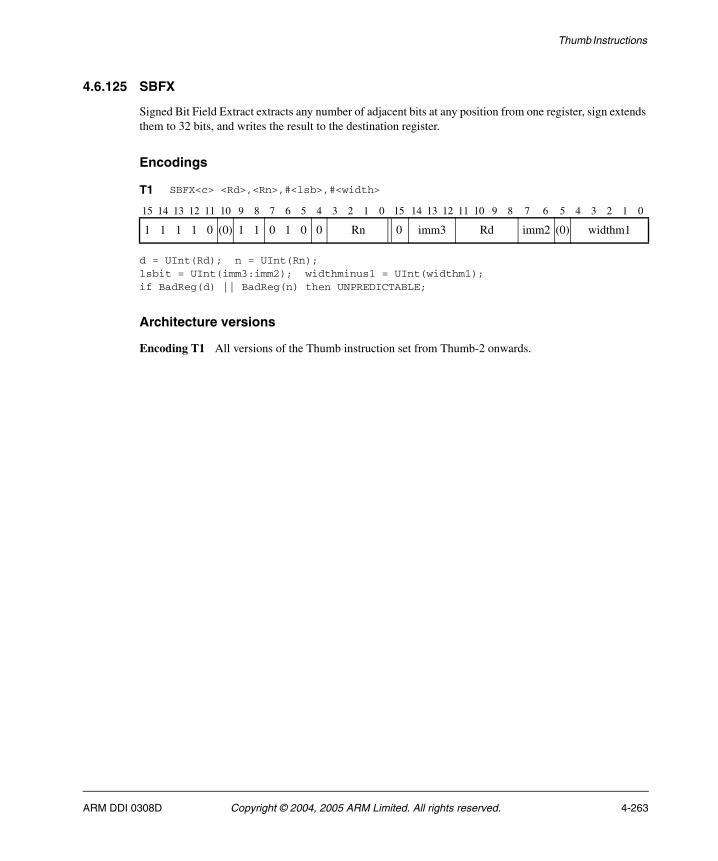
Thumb Instructions
4.6.125 SBFX
Signed Bit Field Extract extracts any number of adjacent bits at any position from one register, sign extends them to 32 bits, and writes the result to the destination register.
Encodings
d = UInt(Rd); n = UInt(Rn);lsbit = UInt(imm3:imm2); widthminus1 = UInt(widthm1);if BadReg(d) || BadReg(n) then UNPREDICTABLE;
Architecture versions
Encoding T1 All versions of the Thumb instruction set from Thumb-2 onwards.
T1 SBFX<c> <Rd>,<Rn>,#<lsb>,#<width>
15 14 13 12 11 10 9 8 7 6 5 4 3 2 1 0 15 14 13 12 11 10 9 8 7 6 5 4 3 2 1 0
1 1 1 1 0 (0) 1 1 0 1 0 0 Rn 0 imm3 Rd imm2 (0) widthm1
ARM DDI 0308D Copyright © 2004, 2005 ARM Limited. All rights reserved. 4-263

Thumb Instructions
Assembler syntax
SBFX<c><q> <Rd>, <Rn>, #<lsb>, #<width>
where:
<c><q> See Standard assembler syntax fields on page 4-6.
<Rd> Specifies the destination register.
<Rn> Specifies the register that contains the first operand.
<lsb> is the bit number of the least significant bit in the bitfield, in the range 0-31. This determines the required value of lsbit.
<width> is the width of the bitfield, in the range 1 to 32-<lsb>. The required value of widthminus1 is <width>-1.
Operation
if ConditionPassed() then EncodingSpecificOperations(); msbit = lsbit + widthminus1; if msbit <= 31 then R[d] = SignExtend(R[n]<msbit:lsbit>, 32); else UNPREDICTABLE;
Exceptions
None.
4-264 Copyright © 2004, 2005 ARM Limited. All rights reserved. ARM DDI 0308D

Thumb Instructions
4.6.126 SDIV
Signed Divide divides a 32-bit signed integer register value by a 32-bit signed integer register value, and writes the result to the destination register. The condition code flags are not affected.
Encodings
d = UInt(Rd); n = UInt(Rn); m = UInt(Rm);if BadReg(d) || BadReg(n) || BadReg(m) then UNPREDICTABLE;
Architecture versions
Encoding T1 Profile R versions of the Thumb instruction set from ARMv7 onwards.
T1 SDIV<c> <Rd>,<Rn>,<Rm>
15 14 13 12 11 10 9 8 7 6 5 4 3 2 1 0 15 14 13 12 11 10 9 8 7 6 5 4 3 2 1 0
1 1 1 1 1 0 1 1 1 0 0 1 Rn (1) (1) (1) (1) Rd 1 1 1 1 Rm
ARM DDI 0308D Copyright © 2004, 2005 ARM Limited. All rights reserved. 4-265
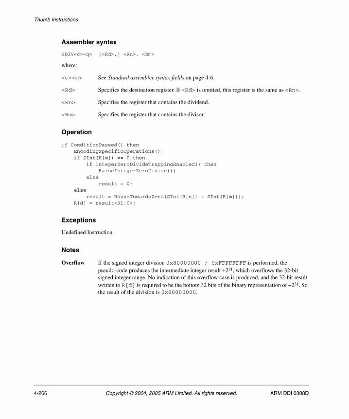
Thumb Instructions
Assembler syntax
SDIV<c><q> {<Rd>,} <Rn>, <Rm>
where:
<c><q> See Standard assembler syntax fields on page 4-6.
<Rd> Specifies the destination register. If <Rd> is omitted, this register is the same as <Rn>.
<Rn> Specifies the register that contains the dividend.
<Rm> Specifies the register that contains the divisor.
Operation
if ConditionPassed() then EncodingSpecificOperations(); if SInt(R[m]) == 0 then if IntegerZeroDivideTrappingEnabled() then RaiseIntegerZeroDivide(); else result = 0; else result = RoundTowardsZero(SInt(R[n]) / SInt(R[m])); R[d] = result<31:0>;
Exceptions
Undefined Instruction.
Notes
Overflow If the signed integer division 0x80000000 / 0xFFFFFFFF is performed, the pseudo-code produces the intermediate integer result +231, which overflows the 32-bit signed integer range. No indication of this overflow case is produced, and the 32-bit result written to R[d] is required to be the bottom 32 bits of the binary representation of +231. So the result of the division is 0x80000000.
4-266 Copyright © 2004, 2005 ARM Limited. All rights reserved. ARM DDI 0308D
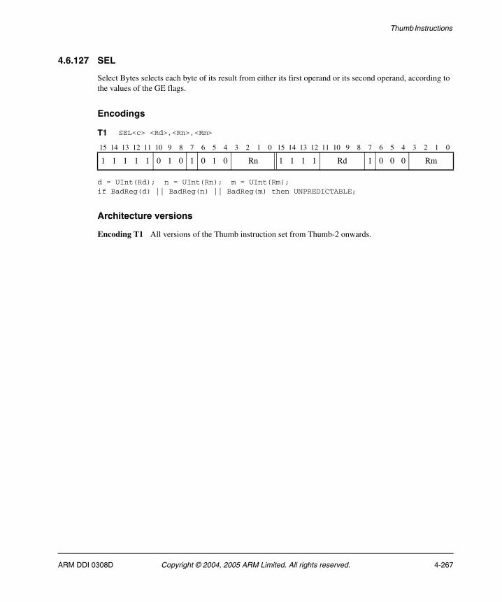
Thumb Instructions
4.6.127 SEL
Select Bytes selects each byte of its result from either its first operand or its second operand, according to the values of the GE flags.
Encodings
d = UInt(Rd); n = UInt(Rn); m = UInt(Rm);if BadReg(d) || BadReg(n) || BadReg(m) then UNPREDICTABLE;
Architecture versions
Encoding T1 All versions of the Thumb instruction set from Thumb-2 onwards.
T1 SEL<c> <Rd>,<Rn>,<Rm>
15 14 13 12 11 10 9 8 7 6 5 4 3 2 1 0 15 14 13 12 11 10 9 8 7 6 5 4 3 2 1 0
1 1 1 1 1 0 1 0 1 0 1 0 Rn 1 1 1 1 Rd 1 0 0 0 Rm
ARM DDI 0308D Copyright © 2004, 2005 ARM Limited. All rights reserved. 4-267
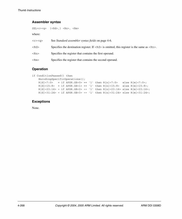
Thumb Instructions
Assembler syntax
SEL<c><q> {<Rd>,} <Rn>, <Rm>
where:
<c><q> See Standard assembler syntax fields on page 4-6.
<Rd> Specifies the destination register. If <Rd> is omitted, this register is the same as <Rn>.
<Rn> Specifies the register that contains the first operand.
<Rm> Specifies the register that contains the second operand.
Operation
if ConditionPassed() then EncodingSpecificOperations(); R[d]<7:0> = if APSR.GE<0> == '1' then R[n]<7:0> else R[m]<7:0>; R[d]<15:8> = if APSR.GE<1> == '1' then R[n]<15:8> else R[m]<15:8>; R[d]<23:16> = if APSR.GE<2> == '1' then R[n]<23:16> else R[m]<23:16>; R[d]<31:24> = if APSR.GE<3> == '1' then R[n]<31:24> else R[m]<31:24>;
Exceptions
None.
4-268 Copyright © 2004, 2005 ARM Limited. All rights reserved. ARM DDI 0308D
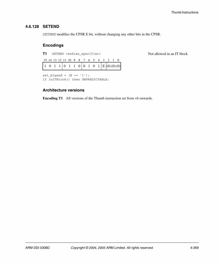
Thumb Instructions
4.6.128 SETEND
SETEND modifies the CPSR E bit, without changing any other bits in the CPSR.
Encodings
set_bigend = (E == '1');if InITBlock() then UNPREDICTABLE;
Architecture versions
Encoding T1 All versions of the Thumb instruction set from v6 onwards.
T1 SETEND <endian_specifier> Not allowed in an IT block
15 14 13 12 11 10 9 8 7 6 5 4 3 2 1 0
1 0 1 1 0 1 1 0 0 1 0 1 E (0) (0) (0)
ARM DDI 0308D Copyright © 2004, 2005 ARM Limited. All rights reserved. 4-269
Thumb Instructions
Assembler syntax
SETEND<q> <endian_specifier>
where:
<q> See Standard assembler syntax fields on page 4-6.
<endian_specifier>
Is one of:
BE Sets the E bit in the instruction. This sets the CPSR E bit.
LE Clears the E bit in the instruction. This clears the CPSR E bit.
Operation
EncodingSpecificOperations();if set_bigend then SetEndianness(Endian_Big);else SetEndianness(Endian_Little);
Exceptions
None.
4-270 Copyright © 2004, 2005 ARM Limited. All rights reserved. ARM DDI 0308D
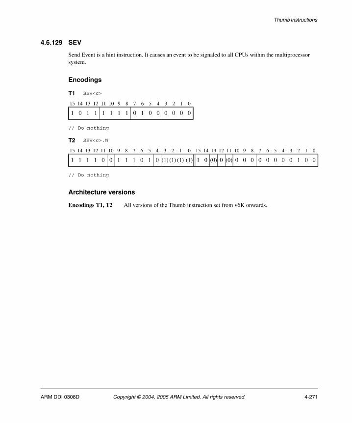
Thumb Instructions
4.6.129 SEV
Send Event is a hint instruction. It causes an event to be signaled to all CPUs within the multiprocessor system.
Encodings
// Do nothing
// Do nothing
Architecture versions
Encodings T1, T2 All versions of the Thumb instruction set from v6K onwards.
T1 SEV<c>
15 14 13 12 11 10 9 8 7 6 5 4 3 2 1 0
1 0 1 1 1 1 1 1 0 1 0 0 0 0 0 0
T2 SEV<c>.W
15 14 13 12 11 10 9 8 7 6 5 4 3 2 1 0 15 14 13 12 11 10 9 8 7 6 5 4 3 2 1 0
1 1 1 1 0 0 1 1 1 0 1 0 (1) (1) (1) (1) 1 0 (0) 0 (0) 0 0 0 0 0 0 0 0 1 0 0
ARM DDI 0308D Copyright © 2004, 2005 ARM Limited. All rights reserved. 4-271

Thumb Instructions
Assembler syntax
SEV<c><q>
where:
<c><q> See Standard assembler syntax fields on page 4-6.
Operation
if ConditionPassed() then EncodingSpecificOperations(); Hint_SendEvent();
Exceptions
None.
4-272 Copyright © 2004, 2005 ARM Limited. All rights reserved. ARM DDI 0308D

Thumb Instructions
4.6.130 SHADD16
Signed Halving Add 16 performs two signed 16-bit integer additions, halves the results, and writes the results to the destination register. It does not affect any flags.
Encodings
d = UInt(Rd); n = UInt(Rn); m = UInt(Rm);if BadReg(d) || BadReg(n) || BadReg(m) then UNPREDICTABLE;
Architecture versions
Encoding T1 All versions of the Thumb instruction set from Thumb-2 onwards.
T1 SHADD16<c> <Rd>,<Rn>,<Rm>
15 14 13 12 11 10 9 8 7 6 5 4 3 2 1 0 15 14 13 12 11 10 9 8 7 6 5 4 3 2 1 0
1 1 1 1 1 0 1 0 1 0 0 1 Rn 1 1 1 1 Rd 0 0 1 0 Rm
ARM DDI 0308D Copyright © 2004, 2005 ARM Limited. All rights reserved. 4-273

Thumb Instructions
Assembler syntax
SHADD16<c><q> {<Rd>,} <Rn>, <Rm>
where:
<c><q> See Standard assembler syntax fields on page 4-6.
<Rd> Specifies the destination register. If <Rd> is omitted, this register is the same as <Rn>.
<Rn> Specifies the register that contains the first operand.
<Rm> Specifies the register that contains the second operand.
Operation
if ConditionPassed() then EncodingSpecificOperations(); sum1 = SInt(R[n]<15:0>) + SInt(R[m]<15:0>); sum2 = SInt(R[n]<31:16>) + SInt(R[m]<31:16>); R[d]<15:0> = sum1<16:1>; R[d]<31:16> = sum2<16:1>;
Exceptions
None.
4-274 Copyright © 2004, 2005 ARM Limited. All rights reserved. ARM DDI 0308D
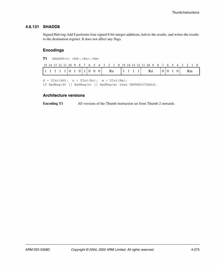
Thumb Instructions
4.6.131 SHADD8
Signed Halving Add 8 performs four signed 8-bit integer additions, halves the results, and writes the results to the destination register. It does not affect any flags.
Encodings
d = UInt(Rd); n = UInt(Rn); m = UInt(Rm);if BadReg(d) || BadReg(n) || BadReg(m) then UNPREDICTABLE;
Architecture versions
Encoding T1 All versions of the Thumb instruction set from Thumb-2 onwards.
T1 SHADD8<c> <Rd>,<Rn>,<Rm>
15 14 13 12 11 10 9 8 7 6 5 4 3 2 1 0 15 14 13 12 11 10 9 8 7 6 5 4 3 2 1 0
1 1 1 1 1 0 1 0 1 0 0 0 Rn 1 1 1 1 Rd 0 0 1 0 Rm
ARM DDI 0308D Copyright © 2004, 2005 ARM Limited. All rights reserved. 4-275
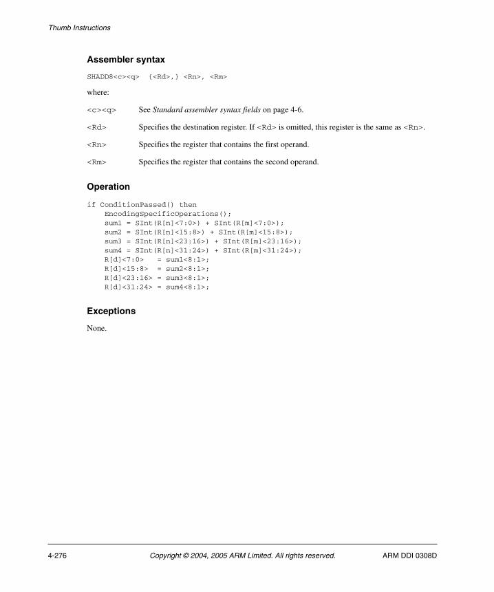
Thumb Instructions
Assembler syntax
SHADD8<c><q> {<Rd>,} <Rn>, <Rm>
where:
<c><q> See Standard assembler syntax fields on page 4-6.
<Rd> Specifies the destination register. If <Rd> is omitted, this register is the same as <Rn>.
<Rn> Specifies the register that contains the first operand.
<Rm> Specifies the register that contains the second operand.
Operation
if ConditionPassed() then EncodingSpecificOperations(); sum1 = SInt(R[n]<7:0>) + SInt(R[m]<7:0>); sum2 = SInt(R[n]<15:8>) + SInt(R[m]<15:8>); sum3 = SInt(R[n]<23:16>) + SInt(R[m]<23:16>); sum4 = SInt(R[n]<31:24>) + SInt(R[m]<31:24>); R[d]<7:0> = sum1<8:1>; R[d]<15:8> = sum2<8:1>; R[d]<23:16> = sum3<8:1>; R[d]<31:24> = sum4<8:1>;
Exceptions
None.
4-276 Copyright © 2004, 2005 ARM Limited. All rights reserved. ARM DDI 0308D

Thumb Instructions
4.6.132 SHASX
Signed Halving Add and Subtract with Exchange exchanges the two halfwords of the second operand, performs one signed 16-bit integer addition and one signed 16-bit subtraction, halves the results, and writes the results to the destination register. It does not affect any flags.
Encodings
d = UInt(Rd); n = UInt(Rn); m = UInt(Rm);if BadReg(d) || BadReg(n) || BadReg(m) then UNPREDICTABLE;
Architecture versions
Encoding T1 All versions of the Thumb instruction set from Thumb-2 onwards.
T1 SHASX<c> <Rd>,<Rn>,<Rm>
15 14 13 12 11 10 9 8 7 6 5 4 3 2 1 0 15 14 13 12 11 10 9 8 7 6 5 4 3 2 1 0
1 1 1 1 1 0 1 0 1 0 1 0 Rn 1 1 1 1 Rd 0 0 1 0 Rm
ARM DDI 0308D Copyright © 2004, 2005 ARM Limited. All rights reserved. 4-277

Thumb Instructions
Assembler syntax
SHASX<c><q> {<Rd>,} <Rn>, <Rm>
where:
<c><q> See Standard assembler syntax fields on page 4-6.
<Rd> Specifies the destination register. If <Rd> is omitted, this register is the same as <Rn>.
<Rn> Specifies the register that contains the first operand.
<Rm> Specifies the register that contains the second operand.
Operation
if ConditionPassed() then EncodingSpecificOperations(); diff = SInt(R[n]<15:0>) - SInt(R[m]<31:16>); sum = SInt(R[n]<31:16>) + SInt(R[m]<15:0>); R[d]<15:0> = diff<16:1>; R[d]<31:16> = sum<16:1>;
Exceptions
None.
4-278 Copyright © 2004, 2005 ARM Limited. All rights reserved. ARM DDI 0308D
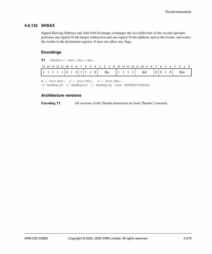
Thumb Instructions
4.6.133 SHSAX
Signed Halving Subtract and Add with Exchange exchanges the two halfwords of the second operand, performs one signed 16-bit integer subtraction and one signed 16-bit addition, halves the results, and writes the results to the destination register. It does not affect any flags.
Encodings
d = UInt(Rd); n = UInt(Rn); m = UInt(Rm);if BadReg(d) || BadReg(n) || BadReg(m) then UNPREDICTABLE;
Architecture versions
Encoding T1 All versions of the Thumb instruction set from Thumb-2 onwards.
T1 SHSAX<c> <Rd>,<Rn>,<Rm>
15 14 13 12 11 10 9 8 7 6 5 4 3 2 1 0 15 14 13 12 11 10 9 8 7 6 5 4 3 2 1 0
1 1 1 1 1 0 1 0 1 1 1 0 Rn 1 1 1 1 Rd 0 0 1 0 Rm
ARM DDI 0308D Copyright © 2004, 2005 ARM Limited. All rights reserved. 4-279

Thumb Instructions
Assembler syntax
SHSAX<c><q> {<Rd>,} <Rn>, <Rm>
where:
<c><q> See Standard assembler syntax fields on page 4-6.
<Rd> Specifies the destination register. If <Rd> is omitted, this register is the same as <Rn>.
<Rn> Specifies the register that contains the first operand.
<Rm> Specifies the register that contains the second operand.
Operation
if ConditionPassed() then EncodingSpecificOperations(); sum = SInt(R[n]<15:0>) + SInt(R[m]<31:16>); diff = SInt(R[n]<31:16>) - SInt(R[m]<15:0>); R[d]<15:0> = sum<16:1>; R[d]<31:16> = diff<16:1>;
Exceptions
None.
4-280 Copyright © 2004, 2005 ARM Limited. All rights reserved. ARM DDI 0308D
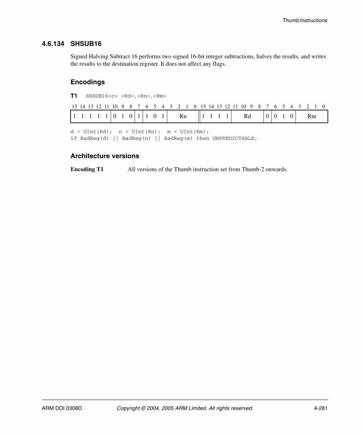
Thumb Instructions
4.6.134 SHSUB16
Signed Halving Subtract 16 performs two signed 16-bit integer subtractions, halves the results, and writes the results to the destination register. It does not affect any flags.
Encodings
d = UInt(Rd); n = UInt(Rn); m = UInt(Rm);if BadReg(d) || BadReg(n) || BadReg(m) then UNPREDICTABLE;
Architecture versions
Encoding T1 All versions of the Thumb instruction set from Thumb-2 onwards.
T1 SHSUB16<c> <Rd>,<Rn>,<Rm>
15 14 13 12 11 10 9 8 7 6 5 4 3 2 1 0 15 14 13 12 11 10 9 8 7 6 5 4 3 2 1 0
1 1 1 1 1 0 1 0 1 1 0 1 Rn 1 1 1 1 Rd 0 0 1 0 Rm
ARM DDI 0308D Copyright © 2004, 2005 ARM Limited. All rights reserved. 4-281

Thumb Instructions
Assembler syntax
SHSUB16<c><q> {<Rd>,} <Rn>, <Rm>
where:
<c><q> See Standard assembler syntax fields on page 4-6.
<Rd> Specifies the destination register. If <Rd> is omitted, this register is the same as <Rn>.
<Rn> Specifies the register that contains the first operand.
<Rm> Specifies the register that contains the second operand.
Operation
if ConditionPassed() then EncodingSpecificOperations(); diff1 = SInt(R[n]<15:0>) - SInt(R[m]<15:0>); diff2 = SInt(R[n]<31:16>) - SInt(R[m]<31:16>); R[d]<15:0> = diff1<16:1>; R[d]<31:16> = diff2<16:1>;
Exceptions
None.
4-282 Copyright © 2004, 2005 ARM Limited. All rights reserved. ARM DDI 0308D

Thumb Instructions
4.6.135 SHSUB8
Signed Halving Subtract 8 performs four signed 8-bit integer subtractions, halves the results, and writes the results to the destination register. It does not affect any flags.
Encodings
d = UInt(Rd); n = UInt(Rn); m = UInt(Rm);if BadReg(d) || BadReg(n) || BadReg(m) then UNPREDICTABLE;
Architecture versions
Encoding T1 All versions of the Thumb instruction set from Thumb-2 onwards.
T1 SHSUB8<c> <Rd>,<Rn>,<Rm>
15 14 13 12 11 10 9 8 7 6 5 4 3 2 1 0 15 14 13 12 11 10 9 8 7 6 5 4 3 2 1 0
1 1 1 1 1 0 1 0 1 1 0 0 Rn 1 1 1 1 Rd 0 0 1 0 Rm
ARM DDI 0308D Copyright © 2004, 2005 ARM Limited. All rights reserved. 4-283

Thumb Instructions
Assembler syntax
SHSUB8<c><q> {<Rd>,} <Rn>, <Rm>
where:
<c><q> See Standard assembler syntax fields on page 4-6.
<Rd> Specifies the destination register. If <Rd> is omitted, this register is the same as <Rn>.
<Rn> Specifies the register that contains the first operand.
<Rm> Specifies the register that contains the second operand.
Operation
if ConditionPassed() then EncodingSpecificOperations(); diff1 = SInt(R[n]<7:0>) - SInt(R[m]<7:0>); diff2 = SInt(R[n]<15:8>) - SInt(R[m]<15:8>); diff3 = SInt(R[n]<23:16>) - SInt(R[m]<23:16>); diff4 = SInt(R[n]<31:24>) - SInt(R[m]<31:24>); R[d]<7:0> = diff1<8:1>; R[d]<15:8> = diff2<8:1>; R[d]<23:16> = diff3<8:1>; R[d]<31:24> = diff4<8:1>;
Exceptions
None.
4-284 Copyright © 2004, 2005 ARM Limited. All rights reserved. ARM DDI 0308D
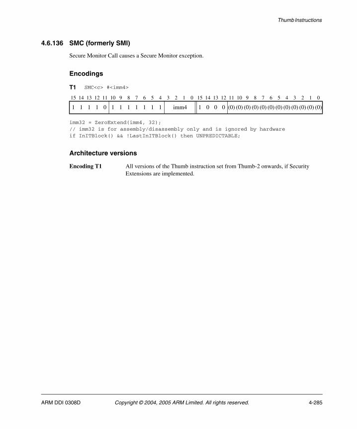
Thumb Instructions
4.6.136 SMC (formerly SMI)
Secure Monitor Call causes a Secure Monitor exception.
Encodings
imm32 = ZeroExtend(imm4, 32);// imm32 is for assembly/disassembly only and is ignored by hardwareif InITBlock() && !LastInITBlock() then UNPREDICTABLE;
Architecture versions
Encoding T1 All versions of the Thumb instruction set from Thumb-2 onwards, if Security Extensions are implemented.
T1 SMC<c> #<imm4>
15 14 13 12 11 10 9 8 7 6 5 4 3 2 1 0 15 14 13 12 11 10 9 8 7 6 5 4 3 2 1 0
1 1 1 1 0 1 1 1 1 1 1 1 imm4 1 0 0 0 (0) (0) (0) (0) (0) (0) (0) (0) (0) (0) (0) (0)
ARM DDI 0308D Copyright © 2004, 2005 ARM Limited. All rights reserved. 4-285
Thumb Instructions
Assembler syntax
SMC<c><q> #<imm4>
where:
<c><q> See Standard assembler syntax fields on page 4-6.
<imm4> Is a 4-bit immediate value. This is ignored by the ARM processor. It can be used by the SMI exception handler (secure monitor code) to determine what service is being requested, but this is not recommended.
The pre-UAL syntax SMI<c> is equivalent to SMC<c>.
Operation
if ConditionPassed() then EncodingSpecificOperations(); CallSecureMonitor();
Exceptions
None.
4-286 Copyright © 2004, 2005 ARM Limited. All rights reserved. ARM DDI 0308D
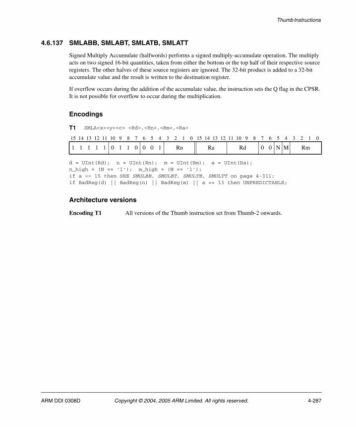
Thumb Instructions
4.6.137 SMLABB, SMLABT, SMLATB, SMLATT
Signed Multiply Accumulate (halfwords) performs a signed multiply-accumulate operation. The multiply acts on two signed 16-bit quantities, taken from either the bottom or the top half of their respective source registers. The other halves of these source registers are ignored. The 32-bit product is added to a 32-bit accumulate value and the result is written to the destination register.
If overflow occurs during the addition of the accumulate value, the instruction sets the Q flag in the CPSR. It is not possible for overflow to occur during the multiplication.
Encodings
d = UInt(Rd); n = UInt(Rn); m = UInt(Rm); a = UInt(Ra);n_high = (N == '1'); m_high = (M == '1');if a == 15 then SEE SMULBB, SMULBT, SMULTB, SMULTT on page 4-311;if BadReg(d) || BadReg(n) || BadReg(m) || a == 13 then UNPREDICTABLE;
Architecture versions
Encoding T1 All versions of the Thumb instruction set from Thumb-2 onwards.
T1 SMLA<x><y><c> <Rd>,<Rn>,<Rm>,<Ra>
15 14 13 12 11 10 9 8 7 6 5 4 3 2 1 0 15 14 13 12 11 10 9 8 7 6 5 4 3 2 1 0
1 1 1 1 1 0 1 1 0 0 0 1 Rn Ra Rd 0 0 N M Rm
ARM DDI 0308D Copyright © 2004, 2005 ARM Limited. All rights reserved. 4-287
Thumb Instructions
Assembler syntax
SMLA<x><y><c><q> <Rd>, <Rn>, <Rm>, <Ra>
where:
<x> Specifies which half of the source register <Rn> is used as the first multiply operand. If <x> is B, then the bottom half (bits[15:0]) of <Rn> is used. If <x> is T, then the top half (bits[31:16]) of <Rn> is used.
<y> Specifies which half of the source register <Rm> is used as the second multiply operand. If <y> is B, then the bottom half (bits[15:0]) of <Rm> is used. If <y> is T, then the top half (bits[31:16]) of <Rm> is used.
<c><q> See Standard assembler syntax fields on page 4-6.
<Rd> Specifies the destination register.
<Rn> Specifies the register that contains the first operand.
<Rm> Specifies the register that contains the second operand.
<Ra> Specifies the register that contains the accumulate value.
Operation
if ConditionPassed() then EncodingSpecificOperations(); operand1 = if n_high then R[n]<31:16> else R[n]<15:0>; operand2 = if m_high then R[m]<31:16> else R[m]<15:0>; result = SInt(operand1) * SInt(operand2) + SInt(R[a]); R[d] = result<31:0>; if result != SInt(result<31:0>) then // Signed overflow APSR.Q = '1';
Exceptions
None.
4-288 Copyright © 2004, 2005 ARM Limited. All rights reserved. ARM DDI 0308D
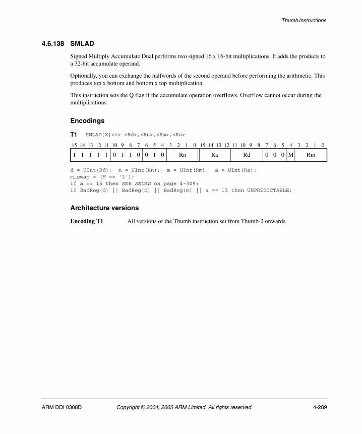
Thumb Instructions
4.6.138 SMLAD
Signed Multiply Accumulate Dual performs two signed 16 x 16-bit multiplications. It adds the products to a 32-bit accumulate operand.
Optionally, you can exchange the halfwords of the second operand before performing the arithmetic. This produces top x bottom and bottom x top multiplication.
This instruction sets the Q flag if the accumulate operation overflows. Overflow cannot occur during the multiplications.
Encodings
d = UInt(Rd); n = UInt(Rn); m = UInt(Rm); a = UInt(Ra);m_swap = (M == '1');if a == 15 then SEE SMUAD on page 4-309;if BadReg(d) || BadReg(n) || BadReg(m) || a == 13 then UNPREDICTABLE;
Architecture versions
Encoding T1 All versions of the Thumb instruction set from Thumb-2 onwards.
T1 SMLAD{X}<c> <Rd>,<Rn>,<Rm>,<Ra>
15 14 13 12 11 10 9 8 7 6 5 4 3 2 1 0 15 14 13 12 11 10 9 8 7 6 5 4 3 2 1 0
1 1 1 1 1 0 1 1 0 0 1 0 Rn Ra Rd 0 0 0 M Rm
ARM DDI 0308D Copyright © 2004, 2005 ARM Limited. All rights reserved. 4-289

Thumb Instructions
Assembler syntax
SMLAD{X}<c><q> <Rd>, <Rn>, <Rm>, <Ra>
where:
X If X is present, the multiplications are bottom x top and top x bottom.
If the X is omitted, the multiplications are bottom x bottom and top x top.
<c><q> See Standard assembler syntax fields on page 4-6.
<Rd> Specifies the destination register.
<Rn> Specifies the register that contains the first operand.
<Rm> Specifies the register that contains the second operand.
<Ra> Specifies the register that contains the accumulate value.
Operation
if ConditionPassed() then EncodingSpecificOperations(); operand2 = if m_swap then ROR(R[m],16) else R[m]; product1 = SInt(R[n]<15:0>) * SInt(operand2<15:0>); product2 = SInt(R[n]<31:16>) * SInt(operand2<31:16>); result = product1 + product2 + SInt(R[a]); R[d] = result<31:0>; if result != SInt(result<31:0>) then // Signed overflow APSR.Q = '1';
Exceptions
None.
4-290 Copyright © 2004, 2005 ARM Limited. All rights reserved. ARM DDI 0308D
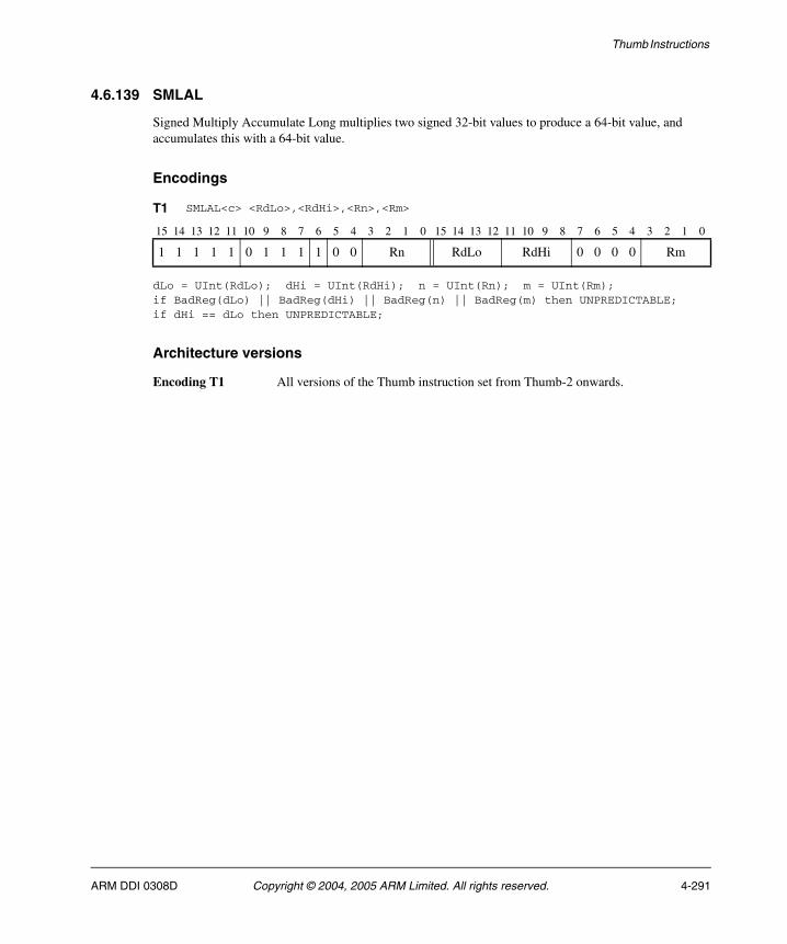
Thumb Instructions
4.6.139 SMLAL
Signed Multiply Accumulate Long multiplies two signed 32-bit values to produce a 64-bit value, and accumulates this with a 64-bit value.
Encodings
dLo = UInt(RdLo); dHi = UInt(RdHi); n = UInt(Rn); m = UInt(Rm);if BadReg(dLo) || BadReg(dHi) || BadReg(n) || BadReg(m) then UNPREDICTABLE;if dHi == dLo then UNPREDICTABLE;
Architecture versions
Encoding T1 All versions of the Thumb instruction set from Thumb-2 onwards.
T1 SMLAL<c> <RdLo>,<RdHi>,<Rn>,<Rm>
15 14 13 12 11 10 9 8 7 6 5 4 3 2 1 0 15 14 13 12 11 10 9 8 7 6 5 4 3 2 1 0
1 1 1 1 1 0 1 1 1 1 0 0 Rn RdLo RdHi 0 0 0 0 Rm
ARM DDI 0308D Copyright © 2004, 2005 ARM Limited. All rights reserved. 4-291
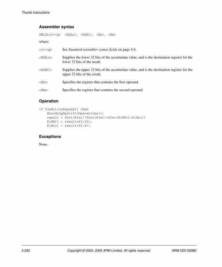
Thumb Instructions
Assembler syntax
SMLAL<c><q> <RdLo>, <RdHi>, <Rn>, <Rm>
where:
<c><q> See Standard assembler syntax fields on page 4-6.
<RdLo> Supplies the lower 32 bits of the accumulate value, and is the destination register for the lower 32 bits of the result.
<RdHi> Supplies the upper 32 bits of the accumulate value, and is the destination register for the upper 32 bits of the result.
<Rn> Specifies the register that contains the first operand.
<Rm> Specifies the register that contains the second operand.
Operation
if ConditionPassed() then EncodingSpecificOperations(); result = SInt(R[n])*Sint(R[m])+SInt(R[dHi]:R[dLo]) R[dHi] = result<63:32>; R[dLo] = result<31:0>;
Exceptions
None.
4-292 Copyright © 2004, 2005 ARM Limited. All rights reserved. ARM DDI 0308D
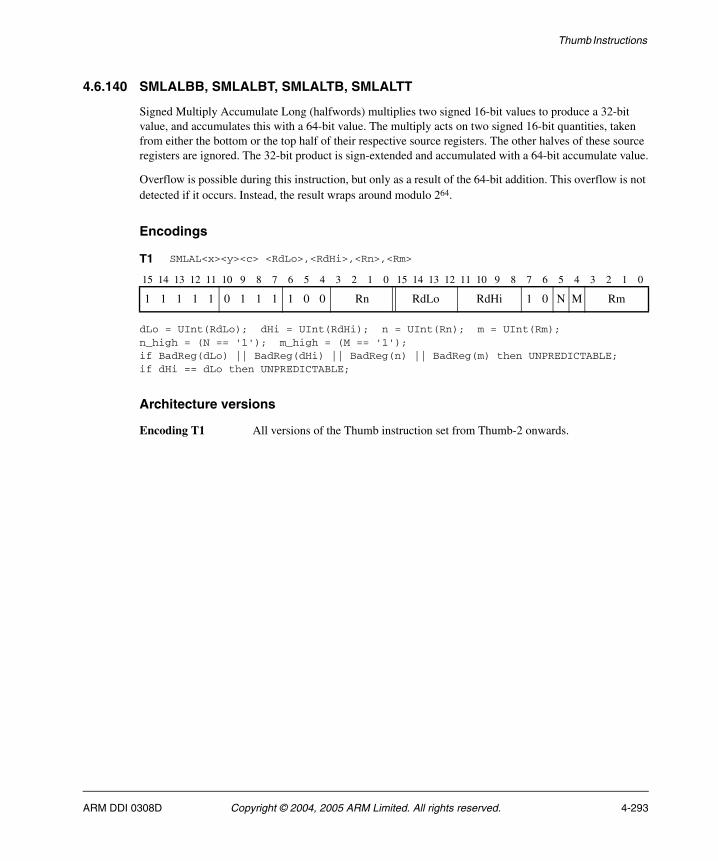
Thumb Instructions
4.6.140 SMLALBB, SMLALBT, SMLALTB, SMLALTT
Signed Multiply Accumulate Long (halfwords) multiplies two signed 16-bit values to produce a 32-bit value, and accumulates this with a 64-bit value. The multiply acts on two signed 16-bit quantities, taken from either the bottom or the top half of their respective source registers. The other halves of these source registers are ignored. The 32-bit product is sign-extended and accumulated with a 64-bit accumulate value.
Overflow is possible during this instruction, but only as a result of the 64-bit addition. This overflow is not detected if it occurs. Instead, the result wraps around modulo 264.
Encodings
dLo = UInt(RdLo); dHi = UInt(RdHi); n = UInt(Rn); m = UInt(Rm);n_high = (N == '1'); m_high = (M == '1');if BadReg(dLo) || BadReg(dHi) || BadReg(n) || BadReg(m) then UNPREDICTABLE;if dHi == dLo then UNPREDICTABLE;
Architecture versions
Encoding T1 All versions of the Thumb instruction set from Thumb-2 onwards.
T1 SMLAL<x><y><c> <RdLo>,<RdHi>,<Rn>,<Rm>
15 14 13 12 11 10 9 8 7 6 5 4 3 2 1 0 15 14 13 12 11 10 9 8 7 6 5 4 3 2 1 0
1 1 1 1 1 0 1 1 1 1 0 0 Rn RdLo RdHi 1 0 N M Rm
ARM DDI 0308D Copyright © 2004, 2005 ARM Limited. All rights reserved. 4-293
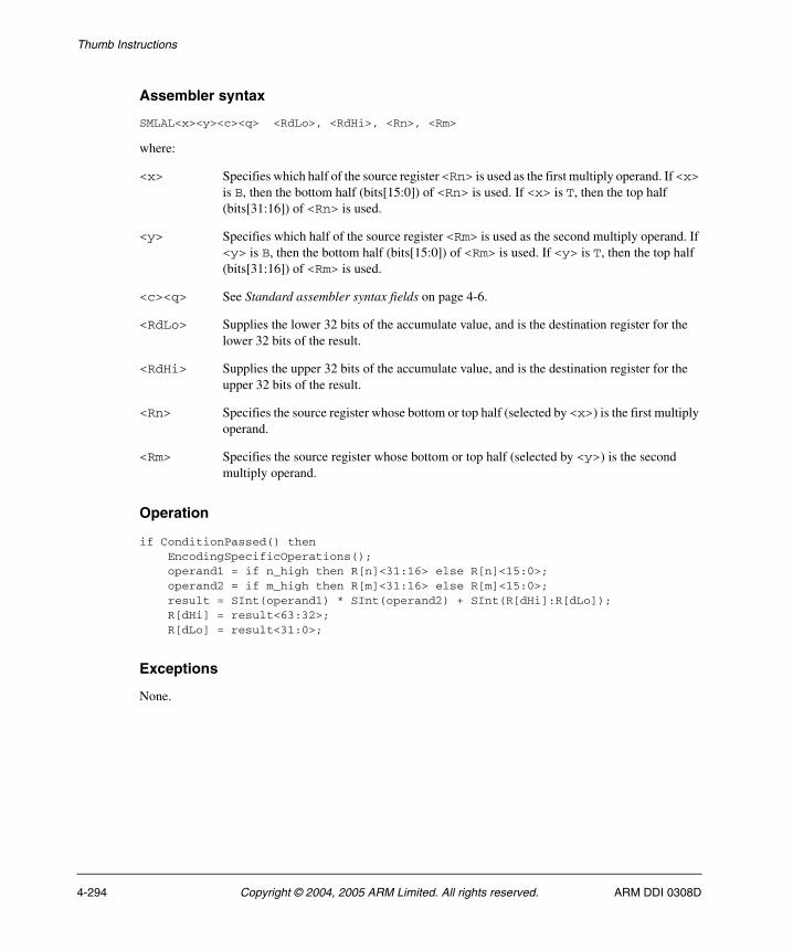
Thumb Instructions
Assembler syntax
SMLAL<x><y><c><q> <RdLo>, <RdHi>, <Rn>, <Rm>
where:
<x> Specifies which half of the source register <Rn> is used as the first multiply operand. If <x> is B, then the bottom half (bits[15:0]) of <Rn> is used. If <x> is T, then the top half (bits[31:16]) of <Rn> is used.
<y> Specifies which half of the source register <Rm> is used as the second multiply operand. If <y> is B, then the bottom half (bits[15:0]) of <Rm> is used. If <y> is T, then the top half (bits[31:16]) of <Rm> is used.
<c><q> See Standard assembler syntax fields on page 4-6.
<RdLo> Supplies the lower 32 bits of the accumulate value, and is the destination register for the lower 32 bits of the result.
<RdHi> Supplies the upper 32 bits of the accumulate value, and is the destination register for the upper 32 bits of the result.
<Rn> Specifies the source register whose bottom or top half (selected by <x>) is the first multiply operand.
<Rm> Specifies the source register whose bottom or top half (selected by <y>) is the second multiply operand.
Operation
if ConditionPassed() then EncodingSpecificOperations(); operand1 = if n_high then R[n]<31:16> else R[n]<15:0>; operand2 = if m_high then R[m]<31:16> else R[m]<15:0>; result = SInt(operand1) * SInt(operand2) + SInt(R[dHi]:R[dLo]); R[dHi] = result<63:32>; R[dLo] = result<31:0>;
Exceptions
None.
4-294 Copyright © 2004, 2005 ARM Limited. All rights reserved. ARM DDI 0308D
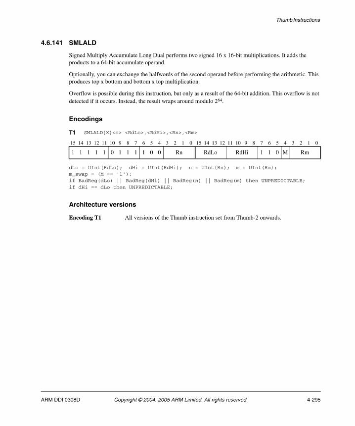
Thumb Instructions
4.6.141 SMLALD
Signed Multiply Accumulate Long Dual performs two signed 16 x 16-bit multiplications. It adds the products to a 64-bit accumulate operand.
Optionally, you can exchange the halfwords of the second operand before performing the arithmetic. This produces top x bottom and bottom x top multiplication.
Overflow is possible during this instruction, but only as a result of the 64-bit addition. This overflow is not detected if it occurs. Instead, the result wraps around modulo 264.
Encodings
dLo = UInt(RdLo); dHi = UInt(RdHi); n = UInt(Rn); m = UInt(Rm);m_swap = (M == '1');if BadReg(dLo) || BadReg(dHi) || BadReg(n) || BadReg(m) then UNPREDICTABLE;if dHi == dLo then UNPREDICTABLE;
Architecture versions
Encoding T1 All versions of the Thumb instruction set from Thumb-2 onwards.
T1 SMLALD{X}<c> <RdLo>,<RdHi>,<Rn>,<Rm>
15 14 13 12 11 10 9 8 7 6 5 4 3 2 1 0 15 14 13 12 11 10 9 8 7 6 5 4 3 2 1 0
1 1 1 1 1 0 1 1 1 1 0 0 Rn RdLo RdHi 1 1 0 M Rm
ARM DDI 0308D Copyright © 2004, 2005 ARM Limited. All rights reserved. 4-295

Thumb Instructions
Assembler syntax
SMLALD{X}<c><q> <RdLo>, <RdHi>, <Rn>, <Rm>
where:
X If X is present, the multiplications are bottom x top and top x bottom.
If the X is omitted, the multiplications are bottom x bottom and top x top.
<c><q> See Standard assembler syntax fields on page 4-6.
<RdLo> Supplies the lower 32 bits of the accumulate value, and is the destination register for the lower 32 bits of the result.
<RdHi> Supplies the upper 32 bits of the accumulate value, and is the destination register for the upper 32 bits of the result.
<Rn> Specifies the register that contains the first operand.
<Rm> Specifies the register that contains the second operand.
Operation
if ConditionPassed() then EncodingSpecificOperations(); operand2 = if m_swap then ROR(R[m],16) else R[m]; product1 = SInt(R[n]<15:0>) * SInt(operand2<15:0>); product2 = SInt(R[n]<31:16>) * SInt(operand2<31:16>); result = product1 + product2 + SInt(R[dHi]:R[dLo]); R[dHi] = result<63:32>; R[dLo] = result<31:0>;
Exceptions
None.
4-296 Copyright © 2004, 2005 ARM Limited. All rights reserved. ARM DDI 0308D
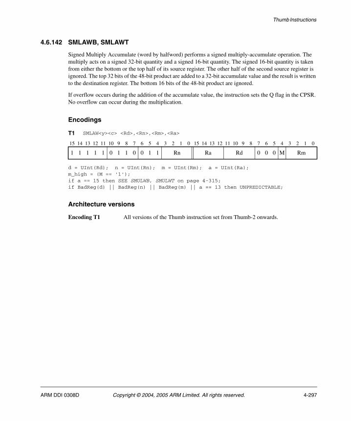
Thumb Instructions
4.6.142 SMLAWB, SMLAWT
Signed Multiply Accumulate (word by halfword) performs a signed multiply-accumulate operation. The multiply acts on a signed 32-bit quantity and a signed 16-bit quantity. The signed 16-bit quantity is taken from either the bottom or the top half of its source register. The other half of the second source register is ignored. The top 32 bits of the 48-bit product are added to a 32-bit accumulate value and the result is written to the destination register. The bottom 16 bits of the 48-bit product are ignored.
If overflow occurs during the addition of the accumulate value, the instruction sets the Q flag in the CPSR. No overflow can occur during the multiplication.
Encodings
d = UInt(Rd); n = UInt(Rn); m = UInt(Rm); a = UInt(Ra);m_high = (M == '1');if a == 15 then SEE SMULWB, SMULWT on page 4-315;if BadReg(d) || BadReg(n) || BadReg(m) || a == 13 then UNPREDICTABLE;
Architecture versions
Encoding T1 All versions of the Thumb instruction set from Thumb-2 onwards.
T1 SMLAW<y><c> <Rd>,<Rn>,<Rm>,<Ra>
15 14 13 12 11 10 9 8 7 6 5 4 3 2 1 0 15 14 13 12 11 10 9 8 7 6 5 4 3 2 1 0
1 1 1 1 1 0 1 1 0 0 1 1 Rn Ra Rd 0 0 0 M Rm
ARM DDI 0308D Copyright © 2004, 2005 ARM Limited. All rights reserved. 4-297
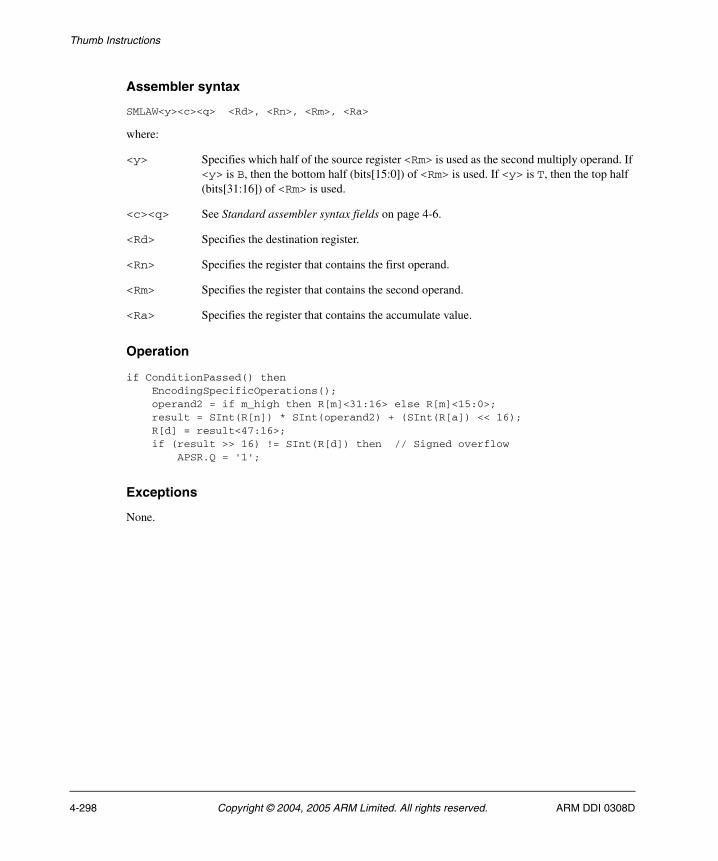
Thumb Instructions
Assembler syntax
SMLAW<y><c><q> <Rd>, <Rn>, <Rm>, <Ra>
where:
<y> Specifies which half of the source register <Rm> is used as the second multiply operand. If <y> is B, then the bottom half (bits[15:0]) of <Rm> is used. If <y> is T, then the top half (bits[31:16]) of <Rm> is used.
<c><q> See Standard assembler syntax fields on page 4-6.
<Rd> Specifies the destination register.
<Rn> Specifies the register that contains the first operand.
<Rm> Specifies the register that contains the second operand.
<Ra> Specifies the register that contains the accumulate value.
Operation
if ConditionPassed() then EncodingSpecificOperations(); operand2 = if m_high then R[m]<31:16> else R[m]<15:0>; result = SInt(R[n]) * SInt(operand2) + (SInt(R[a]) << 16); R[d] = result<47:16>; if (result >> 16) != SInt(R[d]) then // Signed overflow APSR.Q = '1';
Exceptions
None.
4-298 Copyright © 2004, 2005 ARM Limited. All rights reserved. ARM DDI 0308D
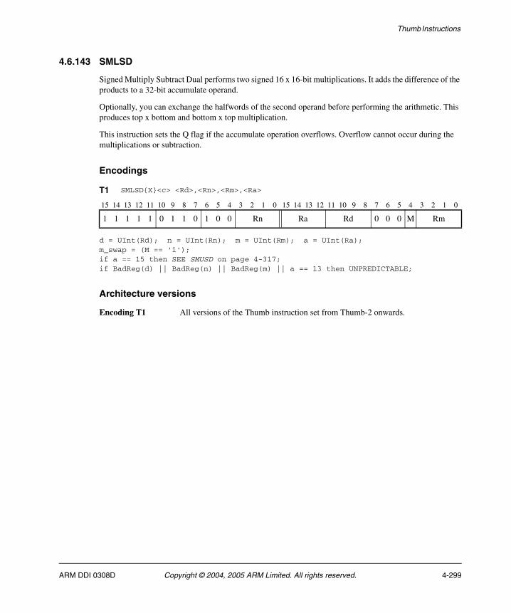
Thumb Instructions
4.6.143 SMLSD
Signed Multiply Subtract Dual performs two signed 16 x 16-bit multiplications. It adds the difference of the products to a 32-bit accumulate operand.
Optionally, you can exchange the halfwords of the second operand before performing the arithmetic. This produces top x bottom and bottom x top multiplication.
This instruction sets the Q flag if the accumulate operation overflows. Overflow cannot occur during the multiplications or subtraction.
Encodings
d = UInt(Rd); n = UInt(Rn); m = UInt(Rm); a = UInt(Ra);m_swap = (M == '1');if a == 15 then SEE SMUSD on page 4-317;if BadReg(d) || BadReg(n) || BadReg(m) || a == 13 then UNPREDICTABLE;
Architecture versions
Encoding T1 All versions of the Thumb instruction set from Thumb-2 onwards.
T1 SMLSD{X}<c> <Rd>,<Rn>,<Rm>,<Ra>
15 14 13 12 11 10 9 8 7 6 5 4 3 2 1 0 15 14 13 12 11 10 9 8 7 6 5 4 3 2 1 0
1 1 1 1 1 0 1 1 0 1 0 0 Rn Ra Rd 0 0 0 M Rm
ARM DDI 0308D Copyright © 2004, 2005 ARM Limited. All rights reserved. 4-299
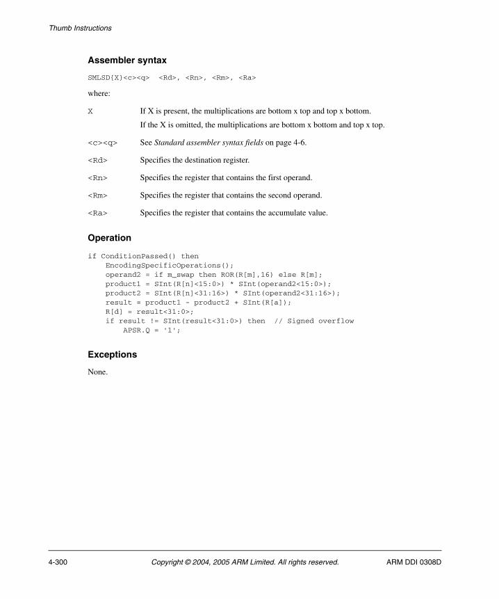
Thumb Instructions
Assembler syntax
SMLSD{X}<c><q> <Rd>, <Rn>, <Rm>, <Ra>
where:
X If X is present, the multiplications are bottom x top and top x bottom.
If the X is omitted, the multiplications are bottom x bottom and top x top.
<c><q> See Standard assembler syntax fields on page 4-6.
<Rd> Specifies the destination register.
<Rn> Specifies the register that contains the first operand.
<Rm> Specifies the register that contains the second operand.
<Ra> Specifies the register that contains the accumulate value.
Operation
if ConditionPassed() then EncodingSpecificOperations(); operand2 = if m_swap then ROR(R[m],16) else R[m]; product1 = SInt(R[n]<15:0>) * SInt(operand2<15:0>); product2 = SInt(R[n]<31:16>) * SInt(operand2<31:16>); result = product1 - product2 + SInt(R[a]); R[d] = result<31:0>; if result != SInt(result<31:0>) then // Signed overflow APSR.Q = '1';
Exceptions
None.
4-300 Copyright © 2004, 2005 ARM Limited. All rights reserved. ARM DDI 0308D
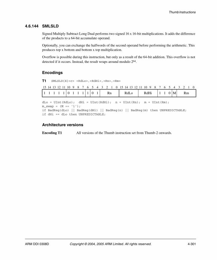
Thumb Instructions
4.6.144 SMLSLD
Signed Multiply Subtract Long Dual performs two signed 16 x 16-bit multiplications. It adds the difference of the products to a 64-bit accumulate operand.
Optionally, you can exchange the halfwords of the second operand before performing the arithmetic. This produces top x bottom and bottom x top multiplication.
Overflow is possible during this instruction, but only as a result of the 64-bit addition. This overflow is not detected if it occurs. Instead, the result wraps around modulo 264.
Encodings
dLo = UInt(RdLo); dHi = UInt(RdHi); n = UInt(Rn); m = UInt(Rm);m_swap = (M == '1');if BadReg(dLo) || BadReg(dHi) || BadReg(n) || BadReg(m) then UNPREDICTABLE;if dHi == dLo then UNPREDICTABLE;
Architecture versions
Encoding T1 All versions of the Thumb instruction set from Thumb-2 onwards.
T1 SMLSLD{X}<c> <RdLo>,<RdHi>,<Rn>,<Rm>
15 14 13 12 11 10 9 8 7 6 5 4 3 2 1 0 15 14 13 12 11 10 9 8 7 6 5 4 3 2 1 0
1 1 1 1 1 0 1 1 1 1 0 1 Rn RdLo RdHi 1 1 0 M Rm
ARM DDI 0308D Copyright © 2004, 2005 ARM Limited. All rights reserved. 4-301
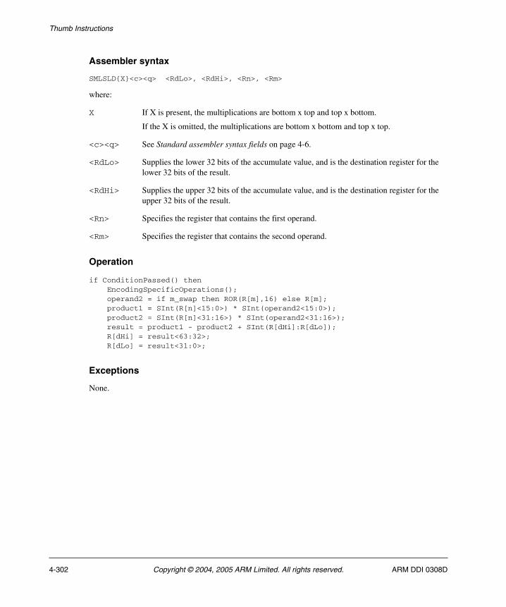
Thumb Instructions
Assembler syntax
SMLSLD{X}<c><q> <RdLo>, <RdHi>, <Rn>, <Rm>
where:
X If X is present, the multiplications are bottom x top and top x bottom.
If the X is omitted, the multiplications are bottom x bottom and top x top.
<c><q> See Standard assembler syntax fields on page 4-6.
<RdLo> Supplies the lower 32 bits of the accumulate value, and is the destination register for the lower 32 bits of the result.
<RdHi> Supplies the upper 32 bits of the accumulate value, and is the destination register for the upper 32 bits of the result.
<Rn> Specifies the register that contains the first operand.
<Rm> Specifies the register that contains the second operand.
Operation
if ConditionPassed() then EncodingSpecificOperations(); operand2 = if m_swap then ROR(R[m],16) else R[m]; product1 = SInt(R[n]<15:0>) * SInt(operand2<15:0>); product2 = SInt(R[n]<31:16>) * SInt(operand2<31:16>); result = product1 - product2 + SInt(R[dHi]:R[dLo]); R[dHi] = result<63:32>; R[dLo] = result<31:0>;
Exceptions
None.
4-302 Copyright © 2004, 2005 ARM Limited. All rights reserved. ARM DDI 0308D
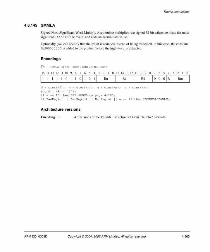
Thumb Instructions
4.6.145 SMMLA
Signed Most Significant Word Multiply Accumulate multiplies two signed 32-bit values, extracts the most significant 32 bits of the result, and adds an accumulate value.
Optionally, you can specify that the result is rounded instead of being truncated. In this case, the constant 0x80000000 is added to the product before the high word is extracted.
Encodings
d = UInt(Rd); n = UInt(Rn); m = UInt(Rm); a = UInt(Ra);round = (R == '1');if a == 15 then SEE SMMUL on page 4-307;if BadReg(d) || BadReg(n) || BadReg(m) || a == 13 then UNPREDICTABLE;
Architecture versions
Encoding T1 All versions of the Thumb instruction set from Thumb-2 onwards.
T1 SMMLA{R}<c> <Rd>,<Rn>,<Rm>,<Ra>
15 14 13 12 11 10 9 8 7 6 5 4 3 2 1 0 15 14 13 12 11 10 9 8 7 6 5 4 3 2 1 0
1 1 1 1 1 0 1 1 0 1 0 1 Rn Ra Rd 0 0 0 R Rm
ARM DDI 0308D Copyright © 2004, 2005 ARM Limited. All rights reserved. 4-303
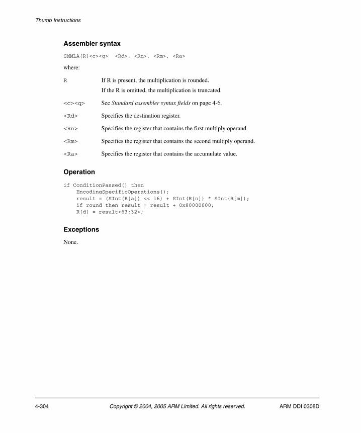
Thumb Instructions
Assembler syntax
SMMLA{R}<c><q> <Rd>, <Rn>, <Rm>, <Ra>
where:
R If R is present, the multiplication is rounded.
If the R is omitted, the multiplication is truncated.
<c><q> See Standard assembler syntax fields on page 4-6.
<Rd> Specifies the destination register.
<Rn> Specifies the register that contains the first multiply operand.
<Rm> Specifies the register that contains the second multiply operand.
<Ra> Specifies the register that contains the accumulate value.
Operation
if ConditionPassed() then EncodingSpecificOperations(); result = (SInt(R[a]) << 16) + SInt(R[n]) * SInt(R[m]); if round then result = result + 0x80000000; R[d] = result<63:32>;
Exceptions
None.
4-304 Copyright © 2004, 2005 ARM Limited. All rights reserved. ARM DDI 0308D
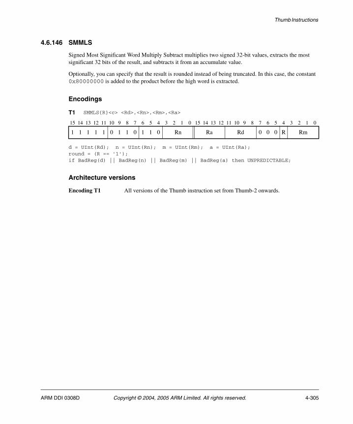
Thumb Instructions
4.6.146 SMMLS
Signed Most Significant Word Multiply Subtract multiplies two signed 32-bit values, extracts the most significant 32 bits of the result, and subtracts it from an accumulate value.
Optionally, you can specify that the result is rounded instead of being truncated. In this case, the constant 0x80000000 is added to the product before the high word is extracted.
Encodings
d = UInt(Rd); n = UInt(Rn); m = UInt(Rm); a = UInt(Ra);round = (R == '1');if BadReg(d) || BadReg(n) || BadReg(m) || BadReg(a) then UNPREDICTABLE;
Architecture versions
Encoding T1 All versions of the Thumb instruction set from Thumb-2 onwards.
T1 SMMLS{R}<c> <Rd>,<Rn>,<Rm>,<Ra>
15 14 13 12 11 10 9 8 7 6 5 4 3 2 1 0 15 14 13 12 11 10 9 8 7 6 5 4 3 2 1 0
1 1 1 1 1 0 1 1 0 1 1 0 Rn Ra Rd 0 0 0 R Rm
ARM DDI 0308D Copyright © 2004, 2005 ARM Limited. All rights reserved. 4-305

Thumb Instructions
Assembler syntax
SMMLS{R}<c><q> <Rd>, <Rn>, <Rm>, <Ra>
where:
R If R is present, the multiplication is rounded.
If the R is omitted, the multiplication is truncated.
<c><q> See Standard assembler syntax fields on page 4-6.
<Rd> Specifies the destination register.
<Rn> Specifies the register that contains the first multiply operand.
<Rm> Specifies the register that contains the second multiply operand.
<Ra> Specifies the register that contains the accumulate value.
Operation
if ConditionPassed() then EncodingSpecificOperations(); result = (SInt(R[a]) << 16) - SInt(R[n]) * SInt(R[m]); if round then result = result + 0x80000000; R[d] = result<63:32>;
Exceptions
None.
4-306 Copyright © 2004, 2005 ARM Limited. All rights reserved. ARM DDI 0308D
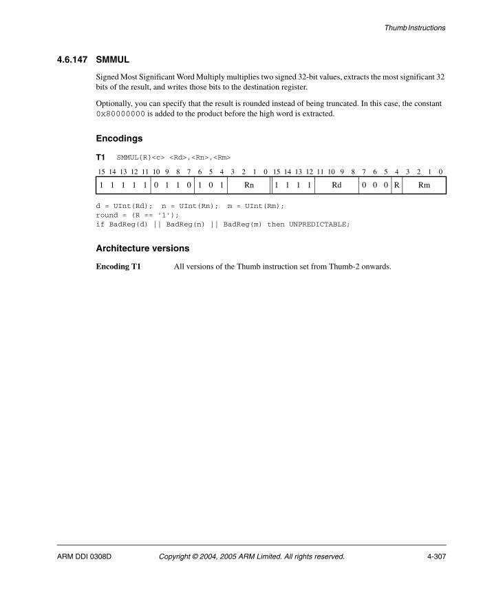
Thumb Instructions
4.6.147 SMMUL
Signed Most Significant Word Multiply multiplies two signed 32-bit values, extracts the most significant 32 bits of the result, and writes those bits to the destination register.
Optionally, you can specify that the result is rounded instead of being truncated. In this case, the constant 0x80000000 is added to the product before the high word is extracted.
Encodings
d = UInt(Rd); n = UInt(Rn); m = UInt(Rm);round = (R == '1');if BadReg(d) || BadReg(n) || BadReg(m) then UNPREDICTABLE;
Architecture versions
Encoding T1 All versions of the Thumb instruction set from Thumb-2 onwards.
T1 SMMUL{R}<c> <Rd>,<Rn>,<Rm>
15 14 13 12 11 10 9 8 7 6 5 4 3 2 1 0 15 14 13 12 11 10 9 8 7 6 5 4 3 2 1 0
1 1 1 1 1 0 1 1 0 1 0 1 Rn 1 1 1 1 Rd 0 0 0 R Rm
ARM DDI 0308D Copyright © 2004, 2005 ARM Limited. All rights reserved. 4-307

Thumb Instructions
Assembler syntax
SMMUL{R}<c><q> {<Rd>,} <Rn>, <Rm>
where:
R If R is present, the multiplication is rounded.
If the R is omitted, the multiplication is truncated.
<c><q> See Standard assembler syntax fields on page 4-6.
<Rd> Specifies the destination register. If <Rd> is omitted, this register is the same as <Rn>.
<Rn> Specifies the register that contains the first operand.
<Rm> Specifies the register that contains the second operand.
Operation
if ConditionPassed() then EncodingSpecificOperations(); result = SInt(R[n]) * SInt(R[m]); if round then result = result + 0x80000000; R[d] = result<63:32>;
Exceptions
None.
4-308 Copyright © 2004, 2005 ARM Limited. All rights reserved. ARM DDI 0308D
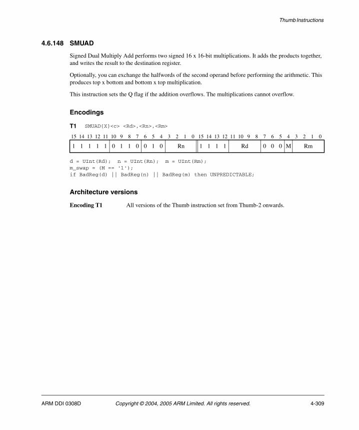
Thumb Instructions
4.6.148 SMUAD
Signed Dual Multiply Add performs two signed 16 x 16-bit multiplications. It adds the products together, and writes the result to the destination register.
Optionally, you can exchange the halfwords of the second operand before performing the arithmetic. This produces top x bottom and bottom x top multiplication.
This instruction sets the Q flag if the addition overflows. The multiplications cannot overflow.
Encodings
d = UInt(Rd); n = UInt(Rn); m = UInt(Rm);m_swap = (M == '1');if BadReg(d) || BadReg(n) || BadReg(m) then UNPREDICTABLE;
Architecture versions
Encoding T1 All versions of the Thumb instruction set from Thumb-2 onwards.
T1 SMUAD{X}<c> <Rd>,<Rn>,<Rm>
15 14 13 12 11 10 9 8 7 6 5 4 3 2 1 0 15 14 13 12 11 10 9 8 7 6 5 4 3 2 1 0
1 1 1 1 1 0 1 1 0 0 1 0 Rn 1 1 1 1 Rd 0 0 0 M Rm
ARM DDI 0308D Copyright © 2004, 2005 ARM Limited. All rights reserved. 4-309

Thumb Instructions
Assembler syntax
SMUAD{x}<c><q> {<Rd>,} <Rn>, <Rm>
where:
X If X is present, the multiplications are bottom x top and top x bottom.
If the X is omitted, the multiplications are bottom x bottom and top x top.
<c><q> See Standard assembler syntax fields on page 4-6.
<Rd> Specifies the destination register. If <Rd> is omitted, this register is the same as <Rn>.
<Rn> Specifies the register that contains the first operand.
<Rm> Specifies the register that contains the second operand.
Operation
if ConditionPassed() then EncodingSpecificOperations(); operand2 = if m_swap then ROR(R[m],16) else R[m]; product1 = SInt(R[n]<15:0>) * SInt(operand2<15:0>); product2 = SInt(R[n]<31:16>) * SInt(operand2<31:16>); result = product1 + product2; R[d] = result<31:0>; if result != SInt(result<31:0>) then // Signed overflow APSR.Q = '1';
Exceptions
None.
4-310 Copyright © 2004, 2005 ARM Limited. All rights reserved. ARM DDI 0308D
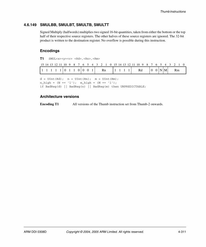
Thumb Instructions
4.6.149 SMULBB, SMULBT, SMULTB, SMULTT
Signed Multiply (halfwords) multiplies two signed 16-bit quantities, taken from either the bottom or the top half of their respective source registers. The other halves of these source registers are ignored. The 32-bit product is written to the destination register. No overflow is possible during this instruction.
Encodings
d = UInt(Rd); n = UInt(Rn); m = UInt(Rm);n_high = (N == '1'); m_high = (M == '1');if BadReg(d) || BadReg(n) || BadReg(m) then UNPREDICTABLE;
Architecture versions
Encoding T1 All versions of the Thumb instruction set from Thumb-2 onwards.
T1 SMUL<x><y><c> <Rd>,<Rn>,<Rm>
15 14 13 12 11 10 9 8 7 6 5 4 3 2 1 0 15 14 13 12 11 10 9 8 7 6 5 4 3 2 1 0
1 1 1 1 1 0 1 1 0 0 0 1 Rn 1 1 1 1 Rd 0 0 N M Rm
ARM DDI 0308D Copyright © 2004, 2005 ARM Limited. All rights reserved. 4-311
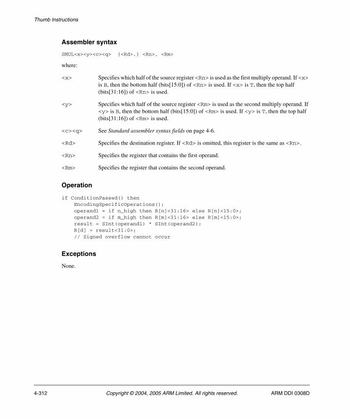
Thumb Instructions
Assembler syntax
SMUL<x><y><c><q> {<Rd>,} <Rn>, <Rm>
where:
<x> Specifies which half of the source register <Rn> is used as the first multiply operand. If <x> is B, then the bottom half (bits[15:0]) of <Rn> is used. If <x> is T, then the top half (bits[31:16]) of <Rn> is used.
<y> Specifies which half of the source register <Rm> is used as the second multiply operand. If <y> is B, then the bottom half (bits[15:0]) of <Rm> is used. If <y> is T, then the top half (bits[31:16]) of <Rm> is used.
<c><q> See Standard assembler syntax fields on page 4-6.
<Rd> Specifies the destination register. If <Rd> is omitted, this register is the same as <Rn>.
<Rn> Specifies the register that contains the first operand.
<Rm> Specifies the register that contains the second operand.
Operation
if ConditionPassed() then EncodingSpecificOperations(); operand1 = if n_high then R[n]<31:16> else R[n]<15:0>; operand2 = if m_high then R[m]<31:16> else R[m]<15:0>; result = SInt(operand1) * SInt(operand2); R[d] = result<31:0>; // Signed overflow cannot occur
Exceptions
None.
4-312 Copyright © 2004, 2005 ARM Limited. All rights reserved. ARM DDI 0308D
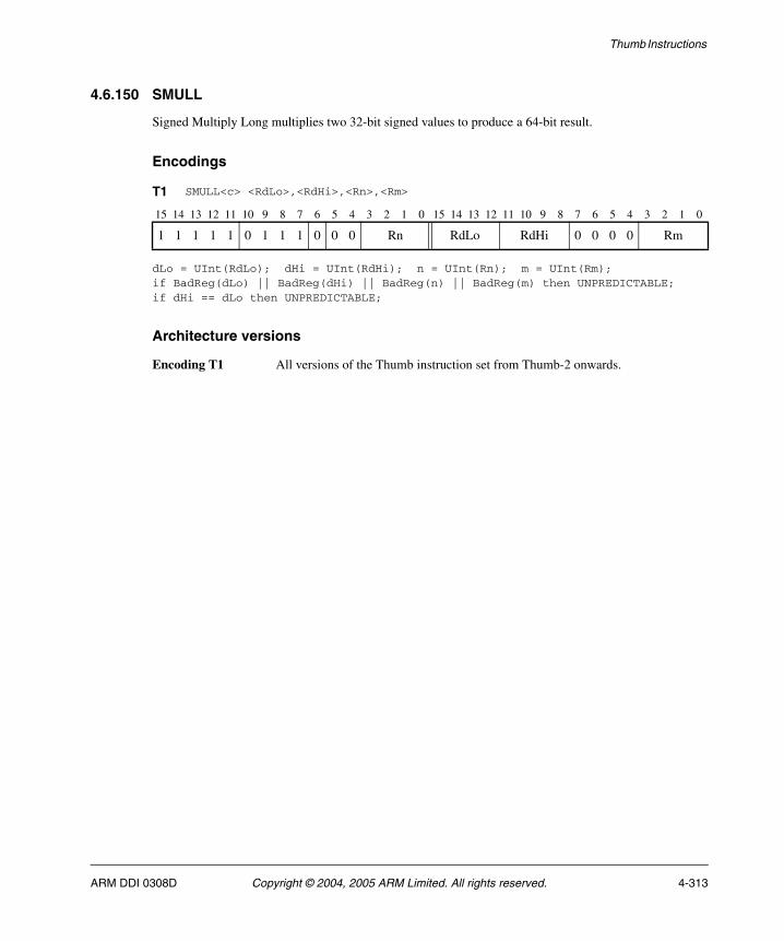
Thumb Instructions
4.6.150 SMULL
Signed Multiply Long multiplies two 32-bit signed values to produce a 64-bit result.
Encodings
dLo = UInt(RdLo); dHi = UInt(RdHi); n = UInt(Rn); m = UInt(Rm);if BadReg(dLo) || BadReg(dHi) || BadReg(n) || BadReg(m) then UNPREDICTABLE;if dHi == dLo then UNPREDICTABLE;
Architecture versions
Encoding T1 All versions of the Thumb instruction set from Thumb-2 onwards.
T1 SMULL<c> <RdLo>,<RdHi>,<Rn>,<Rm>
15 14 13 12 11 10 9 8 7 6 5 4 3 2 1 0 15 14 13 12 11 10 9 8 7 6 5 4 3 2 1 0
1 1 1 1 1 0 1 1 1 0 0 0 Rn RdLo RdHi 0 0 0 0 Rm
ARM DDI 0308D Copyright © 2004, 2005 ARM Limited. All rights reserved. 4-313

Thumb Instructions
Assembler syntax
SMULL<c><q> <RdLo>, <RdHi>, <Rn>, <Rm>
where:
<c><q> See Standard assembler syntax fields on page 4-6.
<RdLo> Stores the lower 32 bits of the result.
<RdHi> Stores the upper 32 bits of the result.
<Rn> Specifies the register that contains the first operand.
<Rm> Specifies the register that contains the second operand.
Operation
if ConditionPassed() then EncodingSpecificOperations(); result = SInt(R[n]) * SInt(R[m]); R[dHi] = result<63:32>; R[dLo] = result<31:0>;
Exceptions
None.
4-314 Copyright © 2004, 2005 ARM Limited. All rights reserved. ARM DDI 0308D
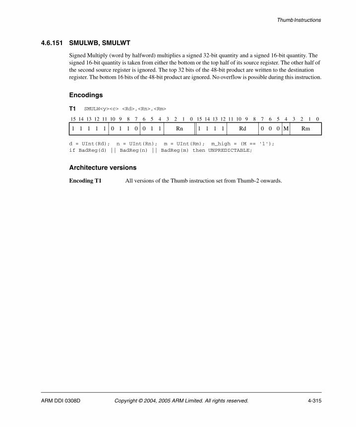
Thumb Instructions
4.6.151 SMULWB, SMULWT
Signed Multiply (word by halfword) multiplies a signed 32-bit quantity and a signed 16-bit quantity. The signed 16-bit quantity is taken from either the bottom or the top half of its source register. The other half of the second source register is ignored. The top 32 bits of the 48-bit product are written to the destination register. The bottom 16 bits of the 48-bit product are ignored. No overflow is possible during this instruction.
Encodings
d = UInt(Rd); n = UInt(Rn); m = UInt(Rm); m_high = (M == '1');if BadReg(d) || BadReg(n) || BadReg(m) then UNPREDICTABLE;
Architecture versions
Encoding T1 All versions of the Thumb instruction set from Thumb-2 onwards.
T1 SMULW<y><c> <Rd>,<Rn>,<Rm>
15 14 13 12 11 10 9 8 7 6 5 4 3 2 1 0 15 14 13 12 11 10 9 8 7 6 5 4 3 2 1 0
1 1 1 1 1 0 1 1 0 0 1 1 Rn 1 1 1 1 Rd 0 0 0 M Rm
ARM DDI 0308D Copyright © 2004, 2005 ARM Limited. All rights reserved. 4-315
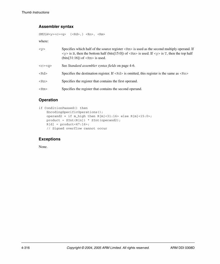
Thumb Instructions
Assembler syntax
SMULW<y><c><q> {<Rd>,} <Rn>, <Rm>
where:
<y> Specifies which half of the source register <Rm> is used as the second multiply operand. If <y> is B, then the bottom half (bits[15:0]) of <Rm> is used. If <y> is T, then the top half (bits[31:16]) of <Rm> is used.
<c><q> See Standard assembler syntax fields on page 4-6.
<Rd> Specifies the destination register. If <Rd> is omitted, this register is the same as <Rn>
<Rn> Specifies the register that contains the first operand.
<Rm> Specifies the register that contains the second operand.
Operation
if ConditionPassed() then EncodingSpecificOperations(); operand2 = if m_high then R[m]<31:16> else R[m]<15:0>; product = SInt(R[n]) * SInt(operand2); R[d] = product<47:16>; // Signed overflow cannot occur
Exceptions
None.
4-316 Copyright © 2004, 2005 ARM Limited. All rights reserved. ARM DDI 0308D
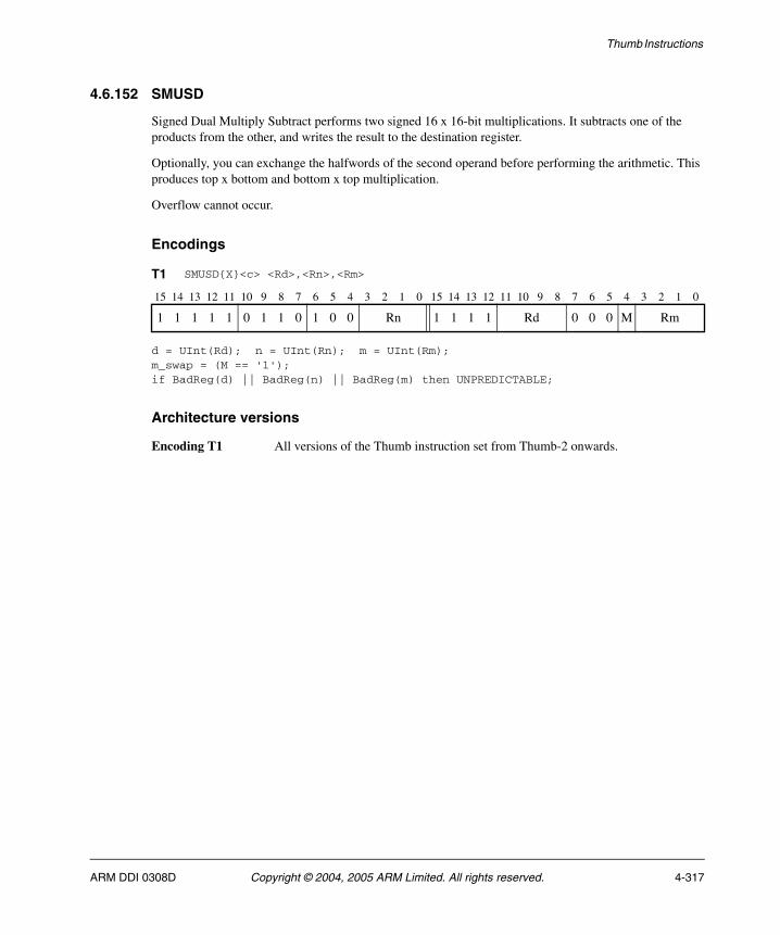
Thumb Instructions
4.6.152 SMUSD
Signed Dual Multiply Subtract performs two signed 16 x 16-bit multiplications. It subtracts one of the products from the other, and writes the result to the destination register.
Optionally, you can exchange the halfwords of the second operand before performing the arithmetic. This produces top x bottom and bottom x top multiplication.
Overflow cannot occur.
Encodings
d = UInt(Rd); n = UInt(Rn); m = UInt(Rm);m_swap = (M == '1');if BadReg(d) || BadReg(n) || BadReg(m) then UNPREDICTABLE;
Architecture versions
Encoding T1 All versions of the Thumb instruction set from Thumb-2 onwards.
T1 SMUSD{X}<c> <Rd>,<Rn>,<Rm>
15 14 13 12 11 10 9 8 7 6 5 4 3 2 1 0 15 14 13 12 11 10 9 8 7 6 5 4 3 2 1 0
1 1 1 1 1 0 1 1 0 1 0 0 Rn 1 1 1 1 Rd 0 0 0 M Rm
ARM DDI 0308D Copyright © 2004, 2005 ARM Limited. All rights reserved. 4-317
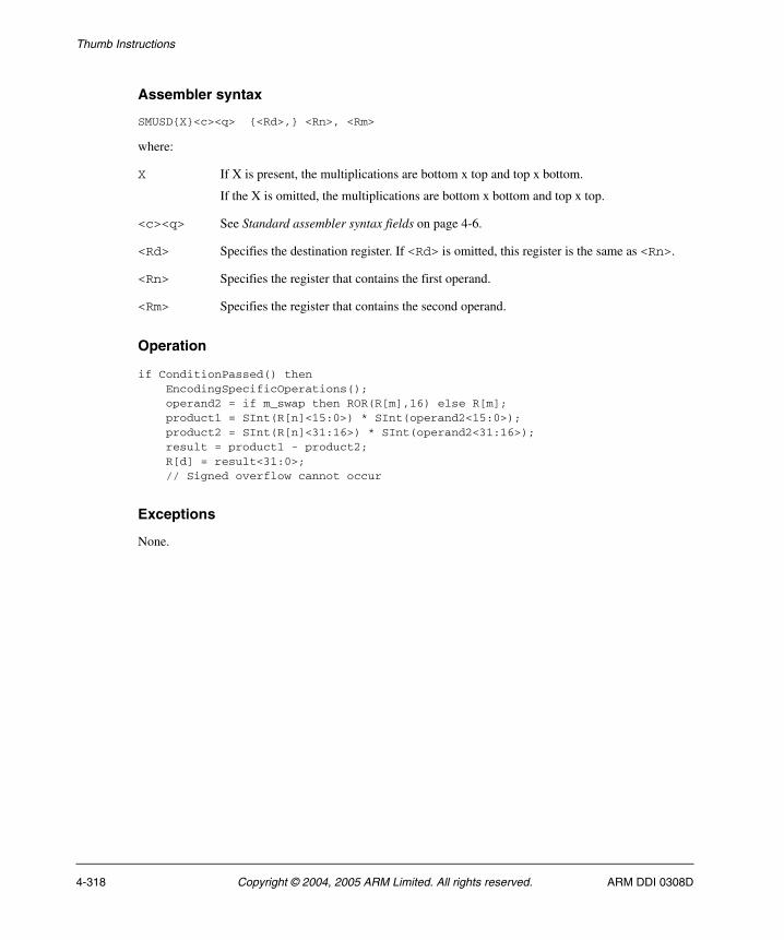
Thumb Instructions
Assembler syntax
SMUSD{X}<c><q> {<Rd>,} <Rn>, <Rm>
where:
X If X is present, the multiplications are bottom x top and top x bottom.
If the X is omitted, the multiplications are bottom x bottom and top x top.
<c><q> See Standard assembler syntax fields on page 4-6.
<Rd> Specifies the destination register. If <Rd> is omitted, this register is the same as <Rn>.
<Rn> Specifies the register that contains the first operand.
<Rm> Specifies the register that contains the second operand.
Operation
if ConditionPassed() then EncodingSpecificOperations(); operand2 = if m_swap then ROR(R[m],16) else R[m]; product1 = SInt(R[n]<15:0>) * SInt(operand2<15:0>); product2 = SInt(R[n]<31:16>) * SInt(operand2<31:16>); result = product1 - product2; R[d] = result<31:0>; // Signed overflow cannot occur
Exceptions
None.
4-318 Copyright © 2004, 2005 ARM Limited. All rights reserved. ARM DDI 0308D
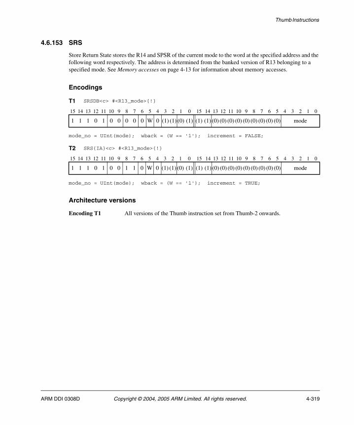
Thumb Instructions
4.6.153 SRS
Store Return State stores the R14 and SPSR of the current mode to the word at the specified address and the following word respectively. The address is determined from the banked version of R13 belonging to a specified mode. See Memory accesses on page 4-13 for information about memory accesses.
Encodings
mode_no = UInt(mode); wback = (W == '1'); increment = FALSE;
mode_no = UInt(mode); wback = (W == '1'); increment = TRUE;
Architecture versions
Encoding T1 All versions of the Thumb instruction set from Thumb-2 onwards.
T1 SRSDB<c> #<R13_mode>{!}
15 14 13 12 11 10 9 8 7 6 5 4 3 2 1 0 15 14 13 12 11 10 9 8 7 6 5 4 3 2 1 0
1 1 1 0 1 0 0 0 0 0 W 0 (1) (1) (0) (1) (1) (1) (0) (0) (0) (0) (0) (0) (0) (0) (0) mode
T2 SRS{IA}<c> #<R13_mode>{!}
15 14 13 12 11 10 9 8 7 6 5 4 3 2 1 0 15 14 13 12 11 10 9 8 7 6 5 4 3 2 1 0
1 1 1 0 1 0 0 1 1 0 W 0 (1) (1) (0) (1) (1) (1) (0) (0) (0) (0) (0) (0) (0) (0) (0) mode
ARM DDI 0308D Copyright © 2004, 2005 ARM Limited. All rights reserved. 4-319

Thumb Instructions
Assembler syntax
SRS{IA|DB}<c><q> #<R13_mode>{!}
where:
<c><q> See Standard assembler syntax fields on page 4-6.
IA Means Increment After. The memory address is incremented after each load operation. This is the default. For this instruction, EA, meaning Empty Ascending, is equivalent to IA.
DB Means Decrement Before. The memory address is decremented before each load operation. For this instruction, FD, meaning Full Descending, is equivalent to DB.
<R13_mode> Specifies the number of the mode whose banked register is used as the base register. The mode number is the 5-bit encoding of the chosen mode in a PSR, as described in the ARM Architecture Reference Manual.
! Causes the instruction to write a modified value back to the base register. If ! is omitted, the instruction does not change the base register.
Operation
if ConditionPassed() then EncodingSpecificOperations(); if !CurrentModeHasSPSR() then UNPREDICTABLE; else base = Rmode[13,mode_no]; address = if increment then base else base-8; wbvalue = if increment then base+8 else base-8; if wback then Rmode[13,mode_no] = wbvalue; MemA[address,4] = LR; MemA[address+4,4] = SPSR;
Exceptions
Data Abort.
4-320 Copyright © 2004, 2005 ARM Limited. All rights reserved. ARM DDI 0308D

Thumb Instructions
4.6.154 SSAT
Signed Saturate saturates an optionally-shifted signed value to a selectable signed range.
The Q flag is set if the operation saturates.
Encodings
d = UInt(Rd); n = UInt(Rn); saturate_to = UInt(sat_imm)+1;if sh == 1 && imm3:imm2 == '00000' then SEE SSAT16 on page 4-323;(shift_t, shift_n) = DecodeImmShift(sh:'0', imm3:imm2);if BadReg(d) || BadReg(n) then UNPREDICTABLE;
Architecture versions
Encoding T1 All versions of the Thumb instruction set from Thumb-2 onwards.
T1 SSAT<c> <Rd>,#<imm>,<Rn>{,<shift>}
15 14 13 12 11 10 9 8 7 6 5 4 3 2 1 0 15 14 13 12 11 10 9 8 7 6 5 4 3 2 1 0
1 1 1 1 0 (0) 1 1 0 0 sh 0 Rn 0 imm3 Rd imm2 (0) sat_imm
ARM DDI 0308D Copyright © 2004, 2005 ARM Limited. All rights reserved. 4-321

Thumb Instructions
Assembler syntax
SSAT<c><q> <Rd>, #<imm>, <Rn> {,<shift>}
where:
<c><q> See Standard assembler syntax fields on page 4-6.
<Rd> Specifies the destination register.
<imm> Specifies the bit position for saturation, in the range 1 to 32.
<Rn> Specifies the register that contains the value to be saturated.
<shift> Specifies the optional shift. If present, it must be one of:
LSL #N N must be in the range 0 to 31.
ASR #N N must be in the range 1 to 31.
If <shift> is omitted, LSL #0 is used.
Operation
if ConditionPassed() then EncodingSpecificOperations(); operand = Shift(R[n], shift_t, shift_n, APSR.C); // APSR.C ignored (result, sat) = SignedSatQ(SInt(operand), saturate_to); R[d] = SignExtend(result, 32); if sat then APSR.Q = '1';
Exceptions
None.
4-322 Copyright © 2004, 2005 ARM Limited. All rights reserved. ARM DDI 0308D

Thumb Instructions
4.6.155 SSAT16
Signed Saturate 16 saturates two signed 16-bit values to a selected signed range.
The Q flag is set if the operation saturates.
Encodings
d = UInt(Rd); n = UInt(Rn); saturate_to = UInt(sat_imm)+1;if BadReg(d) || BadReg(n) then UNPREDICTABLE;
Architecture versions
Encoding T1 All versions of the Thumb instruction set from Thumb-2 onwards.
T1 SSAT16<c> <Rd>,#<imm>,<Rn>
15 14 13 12 11 10 9 8 7 6 5 4 3 2 1 0 15 14 13 12 11 10 9 8 7 6 5 4 3 2 1 0
1 1 1 1 0 (0) 1 1 0 0 1 0 Rn 0 0 0 0 Rd 0 0 (0) (0) sat_imm
ARM DDI 0308D Copyright © 2004, 2005 ARM Limited. All rights reserved. 4-323

Thumb Instructions
Assembler syntax
SSAT16<c><q> <Rd>, #<imm>, <Rn>
where:
<c><q> See Standard assembler syntax fields on page 4-6.
<Rd> Specifies the destination register.
<imm> Specifies the bit position for saturation, in the range 1 to 16.
<Rn> Specifies the register that contains the values to be saturated.
Operation
if ConditionPassed() then EncodingSpecificOperations(); (result1, sat1) = SignedSatQ(SInt(R[n]<15:0>), saturate_to); (result2, sat2) = SignedSatQ(SInt(R[n]<31:16>), saturate_to); R[d]<15:0> = SignExtend(result1, 16); R[d]<31:16> = SignExtend(result2, 16); if sat1 || sat2 then APSR.Q = '1';
Exceptions
None.
4-324 Copyright © 2004, 2005 ARM Limited. All rights reserved. ARM DDI 0308D
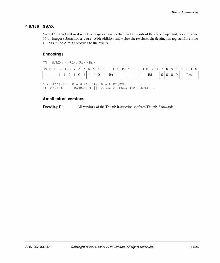
Thumb Instructions
4.6.156 SSAX
Signed Subtract and Add with Exchange exchanges the two halfwords of the second operand, performs one 16-bit integer subtraction and one 16-bit addition, and writes the results to the destination register. It sets the GE bits in the APSR according to the results.
Encodings
d = UInt(Rd); n = UInt(Rn); m = UInt(Rm);if BadReg(d) || BadReg(n) || BadReg(m) then UNPREDICTABLE;
Architecture versions
Encoding T1 All versions of the Thumb instruction set from Thumb-2 onwards.
T1 SSAX<c> <Rd>,<Rn>,<Rm>
15 14 13 12 11 10 9 8 7 6 5 4 3 2 1 0 15 14 13 12 11 10 9 8 7 6 5 4 3 2 1 0
1 1 1 1 1 0 1 0 1 1 1 0 Rn 1 1 1 1 Rd 0 0 0 0 Rm
ARM DDI 0308D Copyright © 2004, 2005 ARM Limited. All rights reserved. 4-325

Thumb Instructions
Assembler syntax
SSAX<c><q> {<Rd>,} <Rn>, <Rm>
where:
<c><q> See Standard assembler syntax fields on page 4-6.
<Rd> Specifies the destination register. If <Rd> is omitted, this register is the same as <Rn>.
<Rn> Specifies the register that contains the first operand.
<Rm> Specifies the register that contains the second operand.
Operation
if ConditionPassed() then EncodingSpecificOperations(); sum = SInt(R[n]<15:0>) + SInt(R[m]<31:16>); diff = SInt(R[n]<31:16>) - SInt(R[m]<15:0>); R[d]<15:0> = sum<15:0>; R[d]<31:16> = diff<15:0>; APSR.GE<1:0> = if sum >= 0 then '11' else '00'; APSR.GE<3:2> = if diff >= 0 then '11' else '00';
Exceptions
None.
4-326 Copyright © 2004, 2005 ARM Limited. All rights reserved. ARM DDI 0308D

Thumb Instructions
4.6.157 SSUB16
Signed Subtract 16 performs two 16-bit signed integer subtractions, and writes the results to the destination register. It sets the GE bits in the APSR according to the results of the subtractions.
Encodings
d = UInt(Rd); n = UInt(Rn); m = UInt(Rm);if BadReg(d) || BadReg(n) || BadReg(m) then UNPREDICTABLE;
Architecture versions
Encoding T1 All versions of the Thumb instruction set from Thumb-2 onwards.
T1 SSUB16<c> <Rd>,<Rn>,<Rm>
15 14 13 12 11 10 9 8 7 6 5 4 3 2 1 0 15 14 13 12 11 10 9 8 7 6 5 4 3 2 1 0
1 1 1 1 1 0 1 0 1 1 0 1 Rn 1 1 1 1 Rd 0 0 0 0 Rm
ARM DDI 0308D Copyright © 2004, 2005 ARM Limited. All rights reserved. 4-327
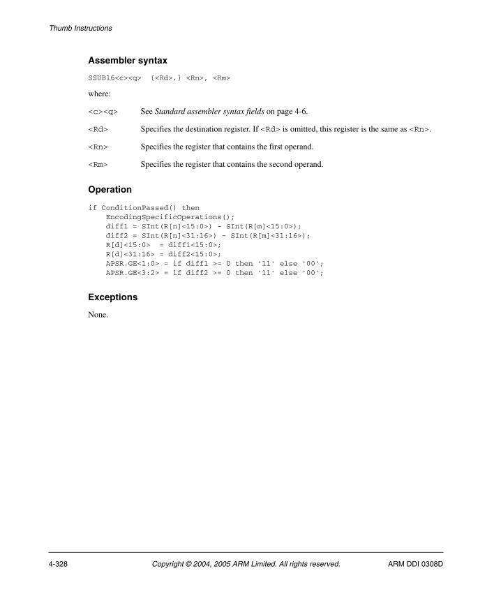
Thumb Instructions
Assembler syntax
SSUB16<c><q> {<Rd>,} <Rn>, <Rm>
where:
<c><q> See Standard assembler syntax fields on page 4-6.
<Rd> Specifies the destination register. If <Rd> is omitted, this register is the same as <Rn>.
<Rn> Specifies the register that contains the first operand.
<Rm> Specifies the register that contains the second operand.
Operation
if ConditionPassed() then EncodingSpecificOperations(); diff1 = SInt(R[n]<15:0>) - SInt(R[m]<15:0>); diff2 = SInt(R[n]<31:16>) - SInt(R[m]<31:16>); R[d]<15:0> = diff1<15:0>; R[d]<31:16> = diff2<15:0>; APSR.GE<1:0> = if diff1 >= 0 then '11' else '00'; APSR.GE<3:2> = if diff2 >= 0 then '11' else '00';
Exceptions
None.
4-328 Copyright © 2004, 2005 ARM Limited. All rights reserved. ARM DDI 0308D

Thumb Instructions
4.6.158 SSUB8
Signed Subtract 8 performs four 8-bit signed integer subtractions, and writes the results to the destination register. It sets the GE bits in the APSR according to the results of the subtractions.
Encodings
d = UInt(Rd); n = UInt(Rn); m = UInt(Rm);if BadReg(d) || BadReg(n) || BadReg(m) then UNPREDICTABLE;
Architecture versions
Encoding T1 All versions of the Thumb instruction set from Thumb-2 onwards.
T1 SSUB8<c> <Rd>,<Rn>,<Rm>
15 14 13 12 11 10 9 8 7 6 5 4 3 2 1 0 15 14 13 12 11 10 9 8 7 6 5 4 3 2 1 0
1 1 1 1 1 0 1 0 1 1 0 0 Rn 1 1 1 1 Rd 0 0 0 0 Rm
ARM DDI 0308D Copyright © 2004, 2005 ARM Limited. All rights reserved. 4-329

Thumb Instructions
Assembler syntax
SSUB8<c><q> {<Rd>,} <Rn>, <Rm>
where:
<c><q> See Standard assembler syntax fields on page 4-6.
<Rd> Specifies the destination register. If <Rd> is omitted, this register is the same as <Rn>.
<Rn> Specifies the register that contains the first operand.
<Rm> Specifies the register that contains the second operand.
Operation
if ConditionPassed() then EncodingSpecificOperations(); diff1 = SInt(R[n]<7:0>) - SInt(R[m]<7:0>); diff2 = SInt(R[n]<15:8>) - SInt(R[m]<15:8>); diff3 = SInt(R[n]<23:16>) - SInt(R[m]<23:16>); diff4 = SInt(R[n]<31:24>) - SInt(R[m]<31:24>); R[d]<7:0> = diff1<7:0>; R[d]<15:8> = diff2<7:0>; R[d]<23:16> = diff3<7:0>; R[d]<31:24> = diff4<7:0>; APSR.GE<0> = if diff1 >= 0 then '1' else '0'; APSR.GE<1> = if diff2 >= 0 then '1' else '0'; APSR.GE<2> = if diff3 >= 0 then '1' else '0'; APSR.GE<3> = if diff4 >= 0 then '1' else '0';
Exceptions
None.
4-330 Copyright © 2004, 2005 ARM Limited. All rights reserved. ARM DDI 0308D
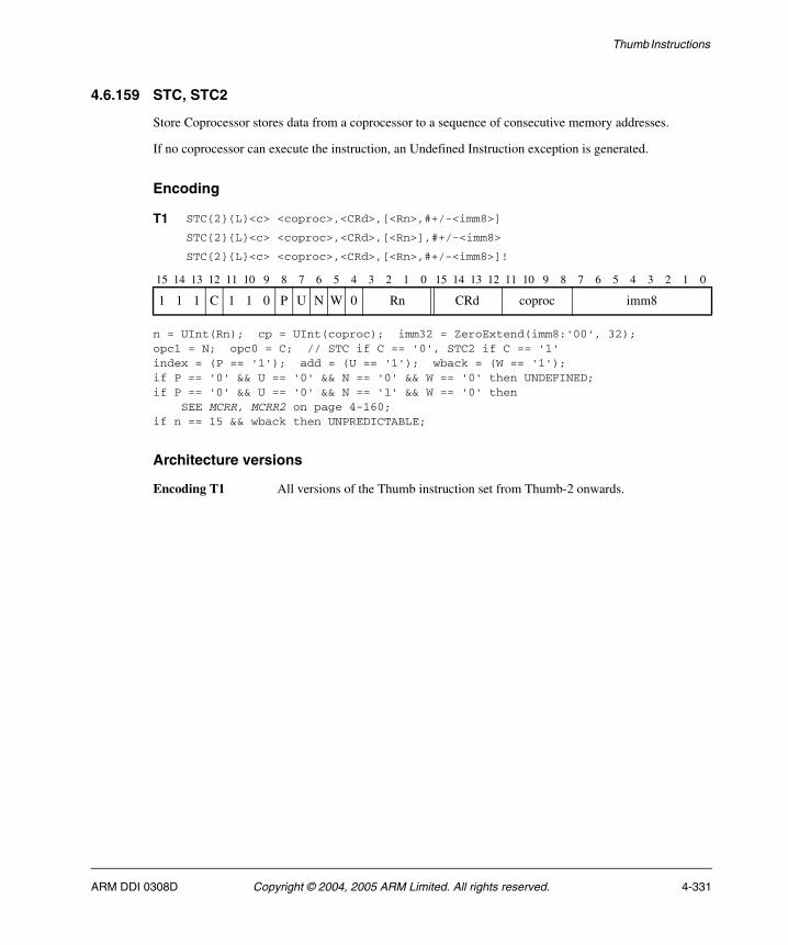
Thumb Instructions
4.6.159 STC, STC2
Store Coprocessor stores data from a coprocessor to a sequence of consecutive memory addresses.
If no coprocessor can execute the instruction, an Undefined Instruction exception is generated.
Encoding
n = UInt(Rn); cp = UInt(coproc); imm32 = ZeroExtend(imm8:'00', 32);opc1 = N; opc0 = C; // STC if C == '0', STC2 if C == '1'index = (P == '1'); add = (U == '1'); wback = (W == '1');if P == '0' && U == '0' && N == '0' && W == '0' then UNDEFINED;if P == '0' && U == '0' && N == '1' && W == '0' then SEE MCRR, MCRR2 on page 4-160;if n == 15 && wback then UNPREDICTABLE;
Architecture versions
Encoding T1 All versions of the Thumb instruction set from Thumb-2 onwards.
T1 STC{2}{L}<c> <coproc>,<CRd>,[<Rn>,#+/-<imm8>]
STC{2}{L}<c> <coproc>,<CRd>,[<Rn>],#+/-<imm8>
STC{2}{L}<c> <coproc>,<CRd>,[<Rn>,#+/-<imm8>]!
15 14 13 12 11 10 9 8 7 6 5 4 3 2 1 0 15 14 13 12 11 10 9 8 7 6 5 4 3 2 1 0
1 1 1 C 1 1 0 P U N W 0 Rn CRd coproc imm8
ARM DDI 0308D Copyright © 2004, 2005 ARM Limited. All rights reserved. 4-331
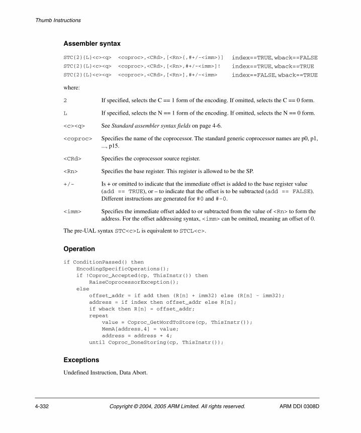
Thumb Instructions
Assembler syntax
where:
2 If specified, selects the C == 1 form of the encoding. If omitted, selects the C == 0 form.
L If specified, selects the N == 1 form of the encoding. If omitted, selects the N == 0 form.
<c><q> See Standard assembler syntax fields on page 4-6.
<coproc> Specifies the name of the coprocessor. The standard generic coprocessor names are p0, p1, ..., p15.
<CRd> Specifies the coprocessor source register.
<Rn> Specifies the base register. This register is allowed to be the SP.
+/- Is + or omitted to indicate that the immediate offset is added to the base register value (add == TRUE), or – to indicate that the offset is to be subtracted (add == FALSE). Different instructions are generated for #0 and #-0.
<imm> Specifies the immediate offset added to or subtracted from the value of <Rn> to form the address. For the offset addressing syntax, <imm> can be omitted, meaning an offset of 0.
The pre-UAL syntax STC<c>L is equivalent to STCL<c>.
Operation
if ConditionPassed() then EncodingSpecificOperations(); if !Coproc_Accepted(cp, ThisInstr()) then RaiseCoprocessorException(); else offset_addr = if add then (R[n] + imm32) else (R[n] - imm32); address = if index then offset_addr else R[n]; if wback then R[n] = offset_addr; repeat value = Coproc_GetWordToStore(cp, ThisInstr()); MemA[address,4] = value; address = address + 4; until Coproc_DoneStoring(cp, ThisInstr());
Exceptions
Undefined Instruction, Data Abort.
STC{2}{L}<c><q> <coproc>,<CRd>,[<Rn>{,#+/-<imm>}] index==TRUE, wback==FALSESTC{2}{L}<c><q> <coproc>,<CRd>,[<Rn>,#+/-<imm>]! index==TRUE, wback==TRUESTC{2}{L}<c><q> <coproc>,<CRd>,[<Rn>],#+/-<imm> index==FALSE, wback==TRUE
4-332 Copyright © 2004, 2005 ARM Limited. All rights reserved. ARM DDI 0308D
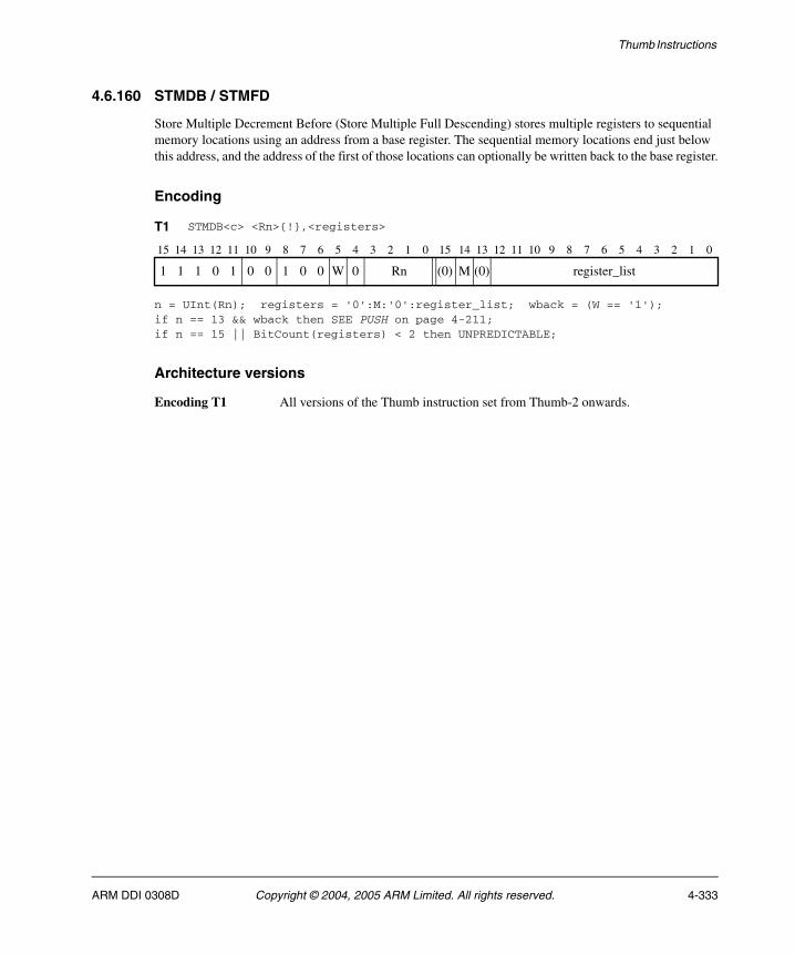
Thumb Instructions
4.6.160 STMDB / STMFD
Store Multiple Decrement Before (Store Multiple Full Descending) stores multiple registers to sequential memory locations using an address from a base register. The sequential memory locations end just below this address, and the address of the first of those locations can optionally be written back to the base register.
Encoding
n = UInt(Rn); registers = '0':M:'0':register_list; wback = (W == '1');if n == 13 && wback then SEE PUSH on page 4-211;if n == 15 || BitCount(registers) < 2 then UNPREDICTABLE;
Architecture versions
Encoding T1 All versions of the Thumb instruction set from Thumb-2 onwards.
T1 STMDB<c> <Rn>{!},<registers>
15 14 13 12 11 10 9 8 7 6 5 4 3 2 1 0 15 14 13 12 11 10 9 8 7 6 5 4 3 2 1 0
1 1 1 0 1 0 0 1 0 0 W 0 Rn (0) M (0) register_list
ARM DDI 0308D Copyright © 2004, 2005 ARM Limited. All rights reserved. 4-333
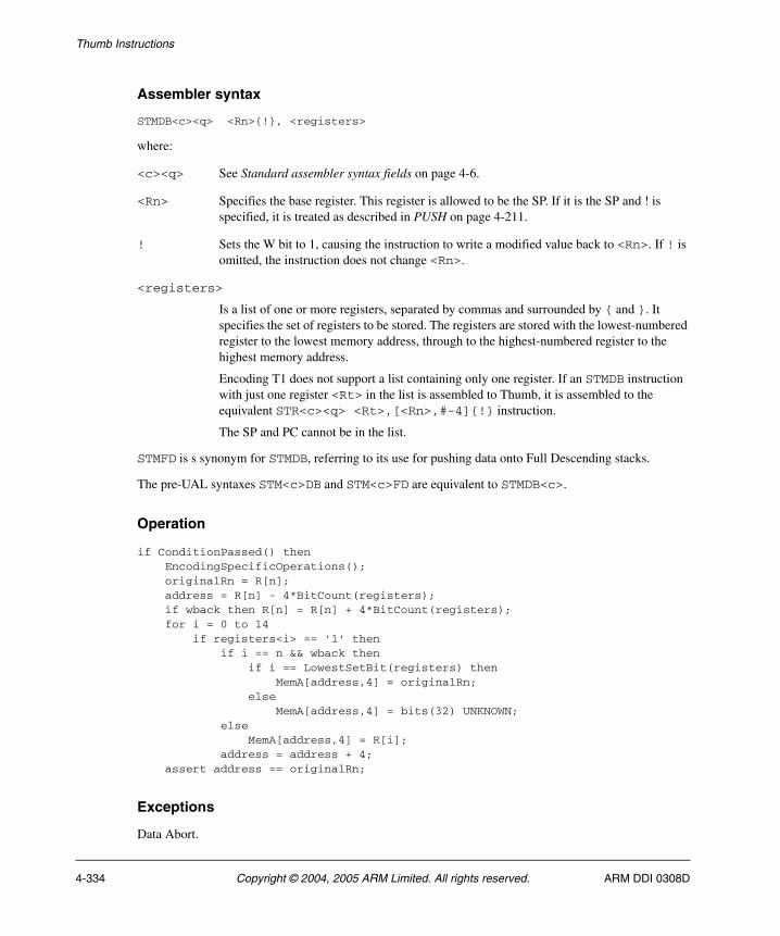
Thumb Instructions
Assembler syntax
STMDB<c><q> <Rn>{!}, <registers>
where:
<c><q> See Standard assembler syntax fields on page 4-6.
<Rn> Specifies the base register. This register is allowed to be the SP. If it is the SP and ! is specified, it is treated as described in PUSH on page 4-211.
! Sets the W bit to 1, causing the instruction to write a modified value back to <Rn>. If ! is omitted, the instruction does not change <Rn>.
<registers>
Is a list of one or more registers, separated by commas and surrounded by { and }. It specifies the set of registers to be stored. The registers are stored with the lowest-numbered register to the lowest memory address, through to the highest-numbered register to the highest memory address.
Encoding T1 does not support a list containing only one register. If an STMDB instruction with just one register <Rt> in the list is assembled to Thumb, it is assembled to the equivalent STR<c><q> <Rt>,[<Rn>,#-4]{!} instruction.
The SP and PC cannot be in the list.
STMFD is s synonym for STMDB, referring to its use for pushing data onto Full Descending stacks.
The pre-UAL syntaxes STM<c>DB and STM<c>FD are equivalent to STMDB<c>.
Operation
if ConditionPassed() then EncodingSpecificOperations(); originalRn = R[n]; address = R[n] - 4*BitCount(registers); if wback then R[n] = R[n] + 4*BitCount(registers); for i = 0 to 14 if registers<i> == '1' then if i == n && wback then if i == LowestSetBit(registers) then MemA[address,4] = originalRn; else MemA[address,4] = bits(32) UNKNOWN; else MemA[address,4] = R[i]; address = address + 4; assert address == originalRn;
Exceptions
Data Abort.
4-334 Copyright © 2004, 2005 ARM Limited. All rights reserved. ARM DDI 0308D

Thumb Instructions
4.6.161 STMIA / STMEA
Store Multiple Increment After (Store Multiple Empty Ascending) stores multiple registers to consecutive memory locations using an address from a base register. The sequential memory locations start at this address, and the address just above the last of those locations can optionally be written back to the base register.
Encoding
n = UInt(Rn); registers = '00000000':register_list; wback = TRUE;if BitCount(registers) < 1 then UNPREDICTABLE;
n = UInt(Rn); registers = '0':M:'0':register_list; wback = (W == '1');if n == 15 || BitCount(registers) < 2 then UNPREDICTABLE;
Architecture versions
Encoding T1 All versions of the Thumb instruction set.
Encoding T2 All versions of the Thumb instruction set from Thumb-2 onwards.
T1 STMIA<c> <Rn>!,<registers>
15 14 13 12 11 10 9 8 7 6 5 4 3 2 1 0
1 1 0 0 0 Rn register_list
T2 STMIA<c>.W <Rn>{!},<registers>
15 14 13 12 11 10 9 8 7 6 5 4 3 2 1 0 15 14 13 12 11 10 9 8 7 6 5 4 3 2 1 0
1 1 1 0 1 0 0 0 1 0 W 0 Rn (0) M (0) register_list
ARM DDI 0308D Copyright © 2004, 2005 ARM Limited. All rights reserved. 4-335
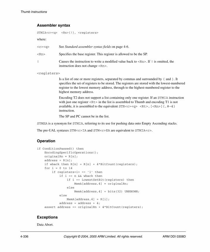
Thumb Instructions
Assembler syntax
STMIA<c><q> <Rn>{!}, <registers>
where:
<c><q> See Standard assembler syntax fields on page 4-6.
<Rn> Specifies the base register. This register is allowed to be the SP.
! Causes the instruction to write a modified value back to <Rn>. If ! is omitted, the instruction does not change <Rn>.
<registers>
Is a list of one or more registers, separated by commas and surrounded by { and }. It specifies the set of registers to be stored. The registers are stored with the lowest-numbered register to the lowest memory address, through to the highest-numbered register to the highest memory address.
Encoding T2 does not support a list containing only one register. If an STMIA instruction with just one register <Rt> in the list is assembled to Thumb and encoding T1 is not available, it is assembled to the equivalent STR<c><q> <Rt>,[<Rn>]{,#-4} instruction.
The SP and PC cannot be in the list.
STMEA is a synonym for STMIA, referring to its use for pushing data onto Empty Ascending stacks.
The pre-UAL syntaxes STM<c>IA and STM<c>EA are equivalent to STMIA<c>.
Operation
if ConditionPassed() then EncodingSpecificOperations(); originalRn = R[n]; address = R[n]; if wback then R[n] = R[n] + 4*BitCount(registers); for i = 0 to 14 if registers<i> == '1' then if i == n && wback then if i == LowestSetBit(registers) then MemA[address,4] = originalRn; else MemA[address,4] = bits(32) UNKNOWN; else MemA[address,4] = R[i]; address = address + 4; assert address == originalRn + 4*BitCount(registers);
Exceptions
Data Abort.
4-336 Copyright © 2004, 2005 ARM Limited. All rights reserved. ARM DDI 0308D
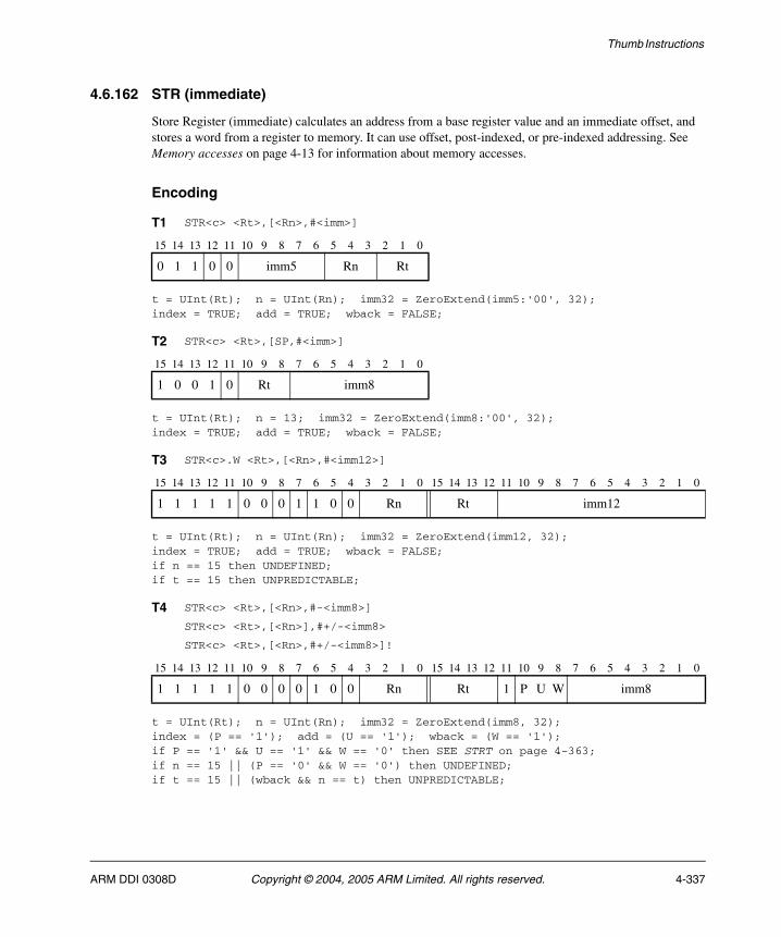
Thumb Instructions
4.6.162 STR (immediate)
Store Register (immediate) calculates an address from a base register value and an immediate offset, and stores a word from a register to memory. It can use offset, post-indexed, or pre-indexed addressing. See Memory accesses on page 4-13 for information about memory accesses.
Encoding
t = UInt(Rt); n = UInt(Rn); imm32 = ZeroExtend(imm5:'00', 32);index = TRUE; add = TRUE; wback = FALSE;
t = UInt(Rt); n = 13; imm32 = ZeroExtend(imm8:'00', 32);index = TRUE; add = TRUE; wback = FALSE;
t = UInt(Rt); n = UInt(Rn); imm32 = ZeroExtend(imm12, 32);index = TRUE; add = TRUE; wback = FALSE;if n == 15 then UNDEFINED;if t == 15 then UNPREDICTABLE;
t = UInt(Rt); n = UInt(Rn); imm32 = ZeroExtend(imm8, 32);index = (P == '1'); add = (U == '1'); wback = (W == '1');if P == '1' && U == '1' && W == '0' then SEE STRT on page 4-363;if n == 15 || (P == '0' && W == '0') then UNDEFINED;if t == 15 || (wback && n == t) then UNPREDICTABLE;
T1 STR<c> <Rt>,[<Rn>,#<imm>]
15 14 13 12 11 10 9 8 7 6 5 4 3 2 1 0
0 1 1 0 0 imm5 Rn Rt
T2 STR<c> <Rt>,[SP,#<imm>]
15 14 13 12 11 10 9 8 7 6 5 4 3 2 1 0
1 0 0 1 0 Rt imm8
T3 STR<c>.W <Rt>,[<Rn>,#<imm12>]
15 14 13 12 11 10 9 8 7 6 5 4 3 2 1 0 15 14 13 12 11 10 9 8 7 6 5 4 3 2 1 0
1 1 1 1 1 0 0 0 1 1 0 0 Rn Rt imm12
T4 STR<c> <Rt>,[<Rn>,#-<imm8>]
STR<c> <Rt>,[<Rn>],#+/-<imm8>
STR<c> <Rt>,[<Rn>,#+/-<imm8>]!
15 14 13 12 11 10 9 8 7 6 5 4 3 2 1 0 15 14 13 12 11 10 9 8 7 6 5 4 3 2 1 0
1 1 1 1 1 0 0 0 0 1 0 0 Rn Rt 1 P U W imm8
ARM DDI 0308D Copyright © 2004, 2005 ARM Limited. All rights reserved. 4-337
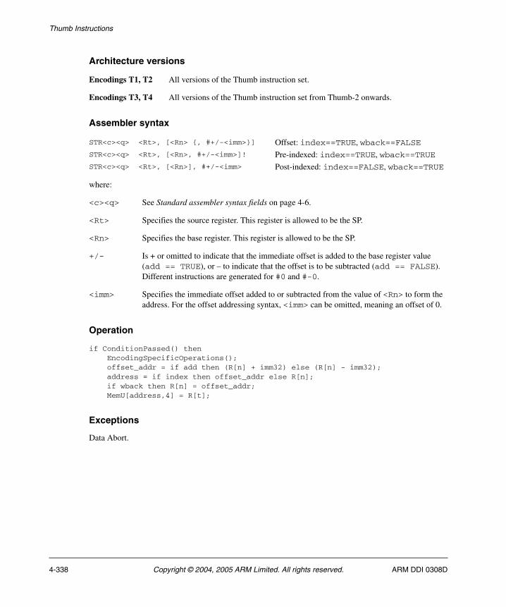
Thumb Instructions
Architecture versions
Encodings T1, T2 All versions of the Thumb instruction set.
Encodings T3, T4 All versions of the Thumb instruction set from Thumb-2 onwards.
Assembler syntax
where:
<c><q> See Standard assembler syntax fields on page 4-6.
<Rt> Specifies the source register. This register is allowed to be the SP.
<Rn> Specifies the base register. This register is allowed to be the SP.
+/- Is + or omitted to indicate that the immediate offset is added to the base register value (add == TRUE), or – to indicate that the offset is to be subtracted (add == FALSE). Different instructions are generated for #0 and #-0.
<imm> Specifies the immediate offset added to or subtracted from the value of <Rn> to form the address. For the offset addressing syntax, <imm> can be omitted, meaning an offset of 0.
Operation
if ConditionPassed() then EncodingSpecificOperations(); offset_addr = if add then (R[n] + imm32) else (R[n] - imm32); address = if index then offset_addr else R[n]; if wback then R[n] = offset_addr; MemU[address,4] = R[t];
Exceptions
Data Abort.
STR<c><q> <Rt>, [<Rn> {, #+/-<imm>}] Offset: index==TRUE, wback==FALSESTR<c><q> <Rt>, [<Rn>, #+/-<imm>]! Pre-indexed: index==TRUE, wback==TRUESTR<c><q> <Rt>, [<Rn>], #+/-<imm> Post-indexed: index==FALSE, wback==TRUE
4-338 Copyright © 2004, 2005 ARM Limited. All rights reserved. ARM DDI 0308D

Thumb Instructions
4.6.163 STR (register)
Store Register (register) calculates an address from a base register value and an offset register value, stores a word from a register to memory. The offset register value can be shifted left by 0, 1, 2, or 3 bits. See Memory accesses on page 4-13 for information about memory accesses.
Encoding
t = UInt(Rt); n = UInt(Rn); m = UInt(Rm);(shift_t, shift_n) = (SRType_None, 0);
t = UInt(Rt); n = UInt(Rn); m = UInt(Rm);(shift_t, shift_n) = (SRType_LSL, UInt(shift));if n == 15 then UNDEFINED;if t == 15 || BadReg(m) then UNPREDICTABLE;
Architecture versions
Encoding T1 All versions of the Thumb instruction set.
Encoding T2 All versions of the Thumb instruction set from Thumb-2 onwards.
T1 STR<c> <Rt>,[<Rn>,<Rm>]
15 14 13 12 11 10 9 8 7 6 5 4 3 2 1 0
0 1 0 1 0 0 0 Rm Rn Rt
T2 STR<c>.W <Rt>,[<Rn>,<Rm>{,LSL #<shift>}]
15 14 13 12 11 10 9 8 7 6 5 4 3 2 1 0 15 14 13 12 11 10 9 8 7 6 5 4 3 2 1 0
1 1 1 1 1 0 0 0 0 1 0 0 Rn Rt 0 0 0 0 0 0 shift Rm
ARM DDI 0308D Copyright © 2004, 2005 ARM Limited. All rights reserved. 4-339
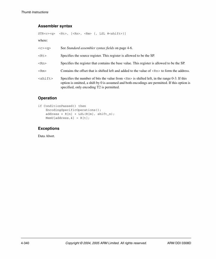
Thumb Instructions
Assembler syntax
STR<c><q> <Rt>, [<Rn>, <Rm> {, LSL #<shift>}]
where:
<c><q> See Standard assembler syntax fields on page 4-6.
<Rt> Specifies the source register. This register is allowed to be the SP.
<Rn> Specifies the register that contains the base value. This register is allowed to be the SP.
<Rm> Contains the offset that is shifted left and added to the value of <Rn> to form the address.
<shift> Specifies the number of bits the value from <Rm> is shifted left, in the range 0-3. If this option is omitted, a shift by 0 is assumed and both encodings are permitted. If this option is specified, only encoding T2 is permitted.
Operation
if ConditionPassed() then EncodingSpecificOperations(); address = R[n] + LSL(R[m], shift_n); MemU[address,4] = R[t];
Exceptions
Data Abort.
4-340 Copyright © 2004, 2005 ARM Limited. All rights reserved. ARM DDI 0308D
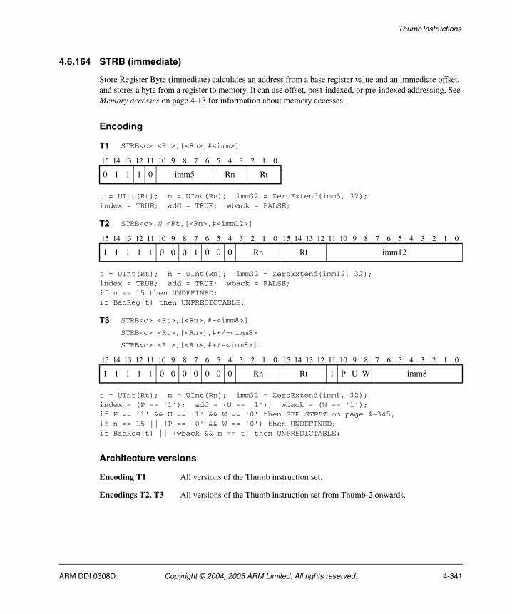
Thumb Instructions
4.6.164 STRB (immediate)
Store Register Byte (immediate) calculates an address from a base register value and an immediate offset, and stores a byte from a register to memory. It can use offset, post-indexed, or pre-indexed addressing. See Memory accesses on page 4-13 for information about memory accesses.
Encoding
t = UInt(Rt); n = UInt(Rn); imm32 = ZeroExtend(imm5, 32);index = TRUE; add = TRUE; wback = FALSE;
t = UInt(Rt); n = UInt(Rn); imm32 = ZeroExtend(imm12, 32);index = TRUE; add = TRUE; wback = FALSE;if n == 15 then UNDEFINED;if BadReg(t) then UNPREDICTABLE;
t = UInt(Rt); n = UInt(Rn); imm32 = ZeroExtend(imm8, 32);index = (P == '1'); add = (U == '1'); wback = (W == '1');if P == '1' && U == '1' && W == '0' then SEE STRBT on page 4-345;if n == 15 || (P == '0' && W == '0') then UNDEFINED;if BadReg(t) || (wback && n == t) then UNPREDICTABLE;
Architecture versions
Encoding T1 All versions of the Thumb instruction set.
Encodings T2, T3 All versions of the Thumb instruction set from Thumb-2 onwards.
T1 STRB<c> <Rt>,[<Rn>,#<imm>]
15 14 13 12 11 10 9 8 7 6 5 4 3 2 1 0
0 1 1 1 0 imm5 Rn Rt
T2 STRB<c>.W <Rt,[<Rn>,#<imm12>]
15 14 13 12 11 10 9 8 7 6 5 4 3 2 1 0 15 14 13 12 11 10 9 8 7 6 5 4 3 2 1 0
1 1 1 1 1 0 0 0 1 0 0 0 Rn Rt imm12
T3 STRB<c> <Rt>,[<Rn>,#-<imm8>]
STRB<c> <Rt>,[<Rn>],#+/-<imm8>
STRB<c> <Rt>,[<Rn>,#+/-<imm8>]!
15 14 13 12 11 10 9 8 7 6 5 4 3 2 1 0 15 14 13 12 11 10 9 8 7 6 5 4 3 2 1 0
1 1 1 1 1 0 0 0 0 0 0 0 Rn Rt 1 P U W imm8
ARM DDI 0308D Copyright © 2004, 2005 ARM Limited. All rights reserved. 4-341
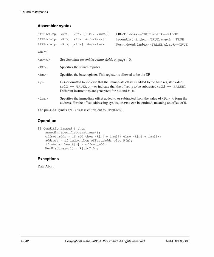
Thumb Instructions
Assembler syntax
where:
<c><q> See Standard assembler syntax fields on page 4-6.
<Rt> Specifies the source register.
<Rn> Specifies the base register. This register is allowed to be the SP.
+/- Is + or omitted to indicate that the immediate offset is added to the base register value (add == TRUE), or – to indicate that the offset is to be subtracted (add == FALSE). Different instructions are generated for #0 and #-0.
<imm> Specifies the immediate offset added to or subtracted from the value of <Rn> to form the address. For the offset addressing syntax, <imm> can be omitted, meaning an offset of 0.
The pre-UAL syntax STR<c>B is equivalent to STRB<c>.
Operation
if ConditionPassed() then EncodingSpecificOperations(); offset_addr = if add then (R[n] + imm32) else (R[n] - imm32); address = if index then offset_addr else R[n]; if wback then R[n] = offset_addr; MemU[address,1] = R[t]<7:0>;
Exceptions
Data Abort.
STRB<c><q> <Rt>, [<Rn> {, #+/-<imm>}] Offset: index==TRUE, wback==FALSESTRB<c><q> <Rt>, [<Rn>, #+/-<imm>]! Pre-indexed: index==TRUE, wback==TRUESTRB<c><q> <Rt>, [<Rn>], #+/-<imm> Post-indexed: index==FALSE, wback==TRUE
4-342 Copyright © 2004, 2005 ARM Limited. All rights reserved. ARM DDI 0308D
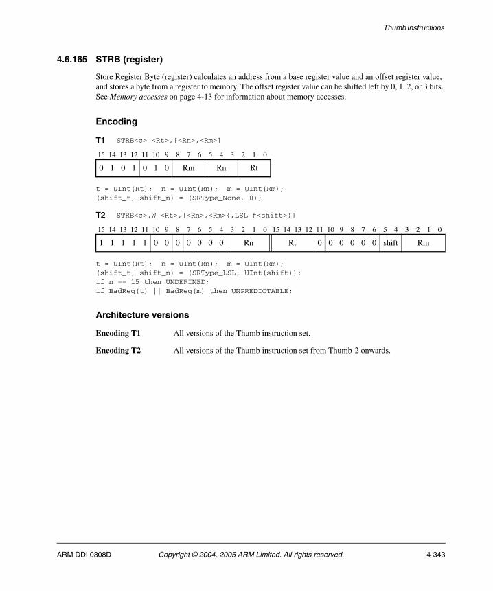
Thumb Instructions
4.6.165 STRB (register)
Store Register Byte (register) calculates an address from a base register value and an offset register value, and stores a byte from a register to memory. The offset register value can be shifted left by 0, 1, 2, or 3 bits. See Memory accesses on page 4-13 for information about memory accesses.
Encoding
t = UInt(Rt); n = UInt(Rn); m = UInt(Rm);(shift_t, shift_n) = (SRType_None, 0);
t = UInt(Rt); n = UInt(Rn); m = UInt(Rm);(shift_t, shift_n) = (SRType_LSL, UInt(shift));if n == 15 then UNDEFINED;if BadReg(t) || BadReg(m) then UNPREDICTABLE;
Architecture versions
Encoding T1 All versions of the Thumb instruction set.
Encoding T2 All versions of the Thumb instruction set from Thumb-2 onwards.
T1 STRB<c> <Rt>,[<Rn>,<Rm>]
15 14 13 12 11 10 9 8 7 6 5 4 3 2 1 0
0 1 0 1 0 1 0 Rm Rn Rt
T2 STRB<c>.W <Rt>,[<Rn>,<Rm>{,LSL #<shift>}]
15 14 13 12 11 10 9 8 7 6 5 4 3 2 1 0 15 14 13 12 11 10 9 8 7 6 5 4 3 2 1 0
1 1 1 1 1 0 0 0 0 0 0 0 Rn Rt 0 0 0 0 0 0 shift Rm
ARM DDI 0308D Copyright © 2004, 2005 ARM Limited. All rights reserved. 4-343
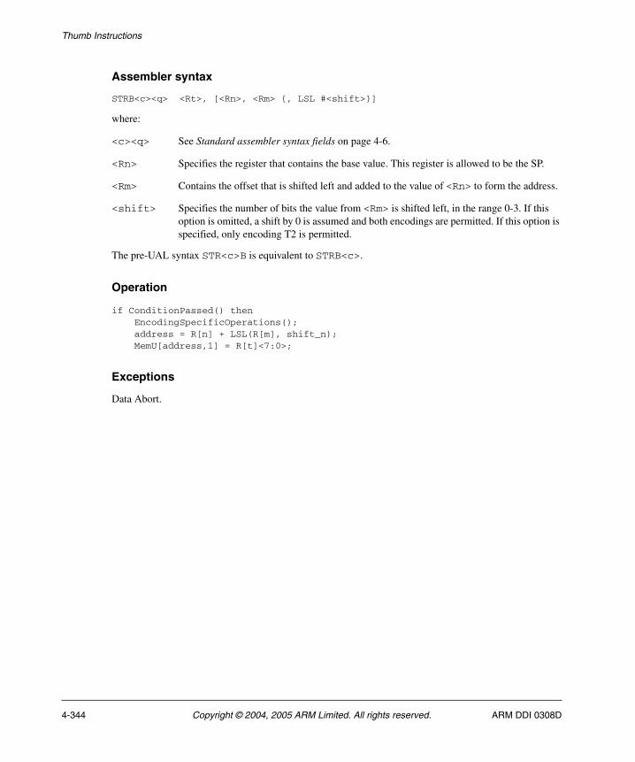
Thumb Instructions
Assembler syntax
STRB<c><q> <Rt>, [<Rn>, <Rm> {, LSL #<shift>}]
where:
<c><q> See Standard assembler syntax fields on page 4-6.
<Rn> Specifies the register that contains the base value. This register is allowed to be the SP.
<Rm> Contains the offset that is shifted left and added to the value of <Rn> to form the address.
<shift> Specifies the number of bits the value from <Rm> is shifted left, in the range 0-3. If this option is omitted, a shift by 0 is assumed and both encodings are permitted. If this option is specified, only encoding T2 is permitted.
The pre-UAL syntax STR<c>B is equivalent to STRB<c>.
Operation
if ConditionPassed() then EncodingSpecificOperations(); address = R[n] + LSL(R[m], shift_n); MemU[address,1] = R[t]<7:0>;
Exceptions
Data Abort.
4-344 Copyright © 2004, 2005 ARM Limited. All rights reserved. ARM DDI 0308D

Thumb Instructions
4.6.166 STRBT
Store Register Byte Unprivileged calculates an address from a base register value and an immediate offset, and stores a byte from a register to memory. See Memory accesses on page 4-13 for information about memory accesses.
The memory access is restricted as if the processor were running in User mode. (This makes no difference if the processor is actually running in User mode.)
Encoding
t = UInt(Rt); n = UInt(Rn); imm32 = ZeroExtend(imm8, 32);if n == 15 then UNDEFINED;if BadReg(t) then UNPREDICTABLE;
Architecture versions
Encoding T1 All versions of the Thumb instruction set from Thumb-2 onwards.
T1 STRBT<c> <Rt>,[<Rn>,#<imm8>]
15 14 13 12 11 10 9 8 7 6 5 4 3 2 1 0 15 14 13 12 11 10 9 8 7 6 5 4 3 2 1 0
1 1 1 1 1 0 0 0 0 0 0 0 Rn Rt 1 1 1 0 imm8
ARM DDI 0308D Copyright © 2004, 2005 ARM Limited. All rights reserved. 4-345

Thumb Instructions
Assembler syntax
STRBT<c><q> <Rt>, [<Rn> {, #<imm>}]
where:
<c><q> See Standard assembler syntax fields on page 4-6.
<Rt> Specifies the source register.
<Rn> Specifies the base register. This register is allowed to be the SP.
<imm> Specifies the immediate offset added to the value of <Rn> to form the address. <imm> can be omitted, meaning an offset of 0.
The pre-UAL syntax STR<c>BT is equivalent to STRBT<c>.
Operation
if ConditionPassed() then EncodingSpecificOperations(); address = R[n] + imm32; MemU_unpriv[address,1] = R[t]<7:0>;
Exceptions
Data Abort.
4-346 Copyright © 2004, 2005 ARM Limited. All rights reserved. ARM DDI 0308D
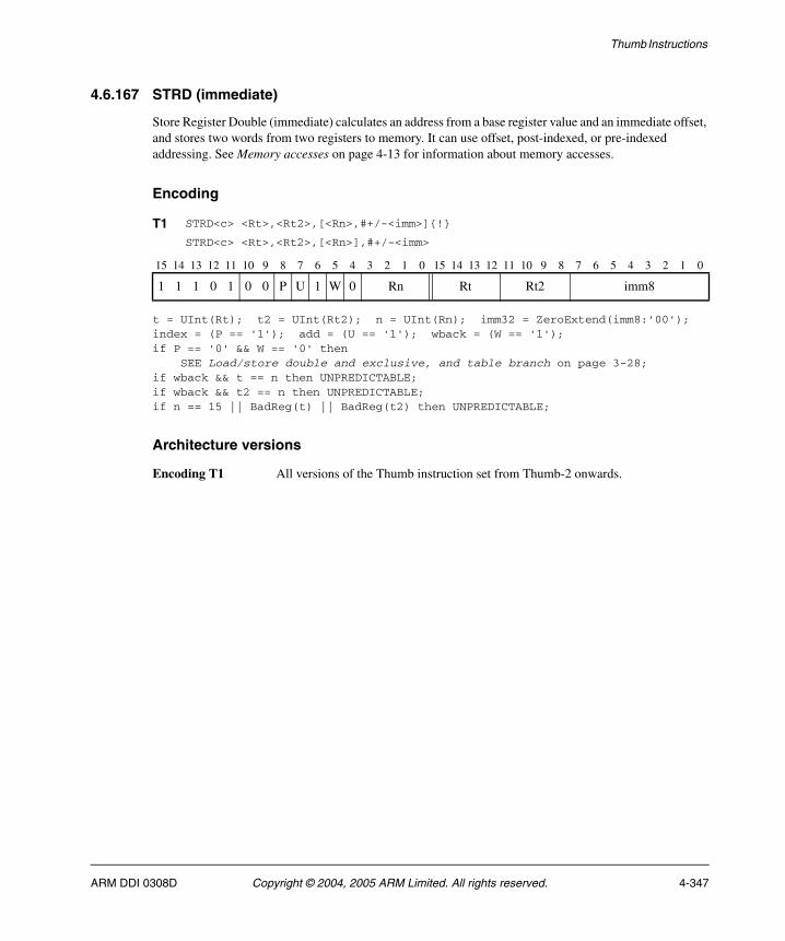
Thumb Instructions
4.6.167 STRD (immediate)
Store Register Double (immediate) calculates an address from a base register value and an immediate offset, and stores two words from two registers to memory. It can use offset, post-indexed, or pre-indexed addressing. See Memory accesses on page 4-13 for information about memory accesses.
Encoding
t = UInt(Rt); t2 = UInt(Rt2); n = UInt(Rn); imm32 = ZeroExtend(imm8:'00');index = (P == '1'); add = (U == '1'); wback = (W == '1');if P == '0' && W == '0' then SEE Load/store double and exclusive, and table branch on page 3-28;if wback && t == n then UNPREDICTABLE;if wback && t2 == n then UNPREDICTABLE;if n == 15 || BadReg(t) || BadReg(t2) then UNPREDICTABLE;
Architecture versions
Encoding T1 All versions of the Thumb instruction set from Thumb-2 onwards.
T1 STRD<c> <Rt>,<Rt2>,[<Rn>,#+/-<imm>]{!}
STRD<c> <Rt>,<Rt2>,[<Rn>],#+/-<imm>
15 14 13 12 11 10 9 8 7 6 5 4 3 2 1 0 15 14 13 12 11 10 9 8 7 6 5 4 3 2 1 0
1 1 1 0 1 0 0 P U 1 W 0 Rn Rt Rt2 imm8
ARM DDI 0308D Copyright © 2004, 2005 ARM Limited. All rights reserved. 4-347
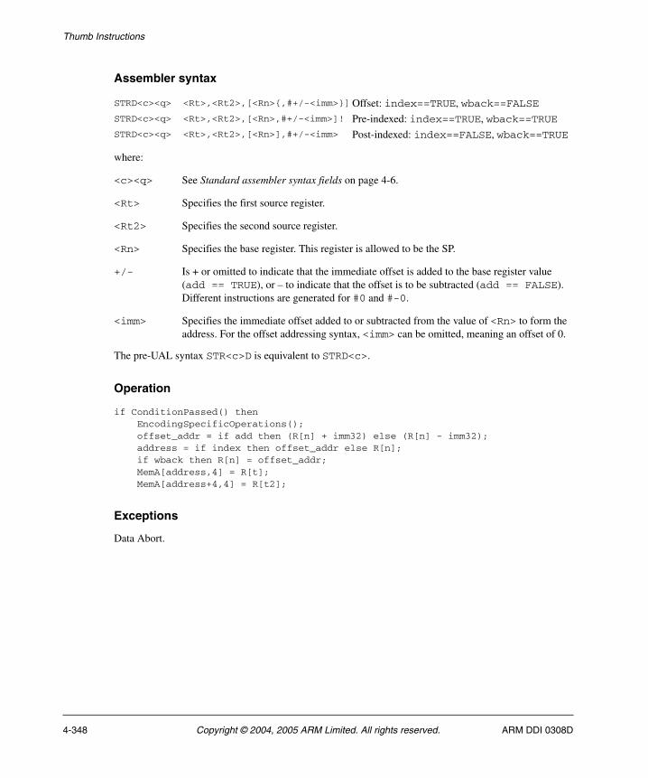
Thumb Instructions
Assembler syntax
where:
<c><q> See Standard assembler syntax fields on page 4-6.
<Rt> Specifies the first source register.
<Rt2> Specifies the second source register.
<Rn> Specifies the base register. This register is allowed to be the SP.
+/- Is + or omitted to indicate that the immediate offset is added to the base register value (add == TRUE), or – to indicate that the offset is to be subtracted (add == FALSE). Different instructions are generated for #0 and #-0.
<imm> Specifies the immediate offset added to or subtracted from the value of <Rn> to form the address. For the offset addressing syntax, <imm> can be omitted, meaning an offset of 0.
The pre-UAL syntax STR<c>D is equivalent to STRD<c>.
Operation
if ConditionPassed() then EncodingSpecificOperations(); offset_addr = if add then (R[n] + imm32) else (R[n] - imm32); address = if index then offset_addr else R[n]; if wback then R[n] = offset_addr; MemA[address,4] = R[t]; MemA[address+4,4] = R[t2];
Exceptions
Data Abort.
STRD<c><q> <Rt>,<Rt2>,[<Rn>{,#+/-<imm>}]Offset: index==TRUE, wback==FALSESTRD<c><q> <Rt>,<Rt2>,[<Rn>,#+/-<imm>]! Pre-indexed: index==TRUE, wback==TRUESTRD<c><q> <Rt>,<Rt2>,[<Rn>],#+/-<imm> Post-indexed: index==FALSE, wback==TRUE
4-348 Copyright © 2004, 2005 ARM Limited. All rights reserved. ARM DDI 0308D
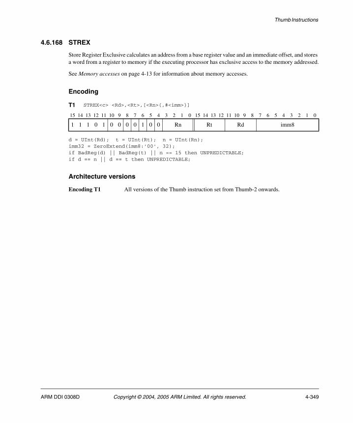
Thumb Instructions
4.6.168 STREX
Store Register Exclusive calculates an address from a base register value and an immediate offset, and stores a word from a register to memory if the executing processor has exclusive access to the memory addressed.
See Memory accesses on page 4-13 for information about memory accesses.
Encoding
d = UInt(Rd); t = UInt(Rt); n = UInt(Rn);imm32 = ZeroExtend(imm8:'00', 32);if BadReg(d) || BadReg(t) || n == 15 then UNPREDICTABLE;if d == n || d == t then UNPREDICTABLE;
Architecture versions
Encoding T1 All versions of the Thumb instruction set from Thumb-2 onwards.
T1 STREX<c> <Rd>,<Rt>,[<Rn>{,#<imm>}]
15 14 13 12 11 10 9 8 7 6 5 4 3 2 1 0 15 14 13 12 11 10 9 8 7 6 5 4 3 2 1 0
1 1 1 0 1 0 0 0 0 1 0 0 Rn Rt Rd imm8
ARM DDI 0308D Copyright © 2004, 2005 ARM Limited. All rights reserved. 4-349

Thumb Instructions
Assembler syntax
STREX<c><q> <Rd>, <Rt>, [<Rn> {,#<imm>}]
where:
<c><q> See Standard assembler syntax fields on page 4-6.
<Rd> Specifies the destination register for the returned status value. The value returned is:
0 if the operation updates memory
1 if the operation fails to update memory.
<Rt> Specifies the source register.
<Rn> Specifies the base register. This register is allowed to be the SP.
<imm> Specifies the immediate offset added to or subtracted from the value of <Rn> to form the address. <imm> can be omitted, meaning an offset of 0.
Operation
if ConditionPassed() then EncodingSpecificOperations(); address = R[n] + imm32; if ExclusiveMonitorsPass(address,4) then MemAA[address,4] = R[t]; R[d] = 0; else R[d] = 1;
Exceptions
Data Abort.
4-350 Copyright © 2004, 2005 ARM Limited. All rights reserved. ARM DDI 0308D
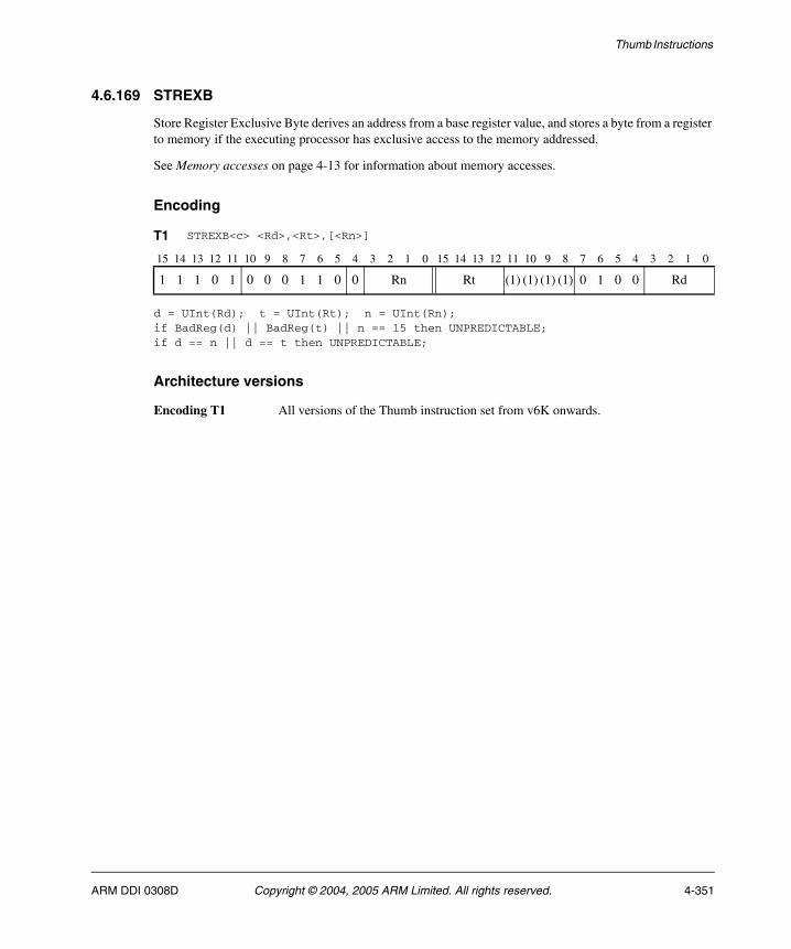
Thumb Instructions
4.6.169 STREXB
Store Register Exclusive Byte derives an address from a base register value, and stores a byte from a register to memory if the executing processor has exclusive access to the memory addressed.
See Memory accesses on page 4-13 for information about memory accesses.
Encoding
d = UInt(Rd); t = UInt(Rt); n = UInt(Rn);if BadReg(d) || BadReg(t) || n == 15 then UNPREDICTABLE;if d == n || d == t then UNPREDICTABLE;
Architecture versions
Encoding T1 All versions of the Thumb instruction set from v6K onwards.
T1 STREXB<c> <Rd>,<Rt>,[<Rn>]
15 14 13 12 11 10 9 8 7 6 5 4 3 2 1 0 15 14 13 12 11 10 9 8 7 6 5 4 3 2 1 0
1 1 1 0 1 0 0 0 1 1 0 0 Rn Rt (1) (1) (1) (1) 0 1 0 0 Rd
ARM DDI 0308D Copyright © 2004, 2005 ARM Limited. All rights reserved. 4-351

Thumb Instructions
Assembler syntax
STREXB<c><q> <Rd>, <Rt>, [<Rn>]
where:
<c><q> See Standard assembler syntax fields on page 4-6.
<Rd> Specifies the destination register for the returned status value. The value returned is:
0 if the operation updates memory
1 if the operation fails to update memory.
<Rt> Specifies the source register.
<Rn> Specifies the base register. This register is allowed to be the SP.
Operation
if ConditionPassed() then EncodingSpecificOperations(); address = R[n]; if ExclusiveMonitorsPass(address,1) then MemAA[address,1] = R[t]; R[d] = 0; else R[d] = 1;
Exceptions
Data Abort.
4-352 Copyright © 2004, 2005 ARM Limited. All rights reserved. ARM DDI 0308D
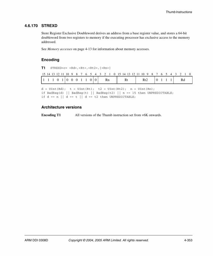
Thumb Instructions
4.6.170 STREXD
Store Register Exclusive Doubleword derives an address from a base register value, and stores a 64-bit doubleword from two registers to memory if the executing processor has exclusive access to the memory addressed.
See Memory accesses on page 4-13 for information about memory accesses.
Encoding
d = UInt(Rd); t = UInt(Rt); t2 = UInt(Rt2); n = UInt(Rn);if BadReg(d) || BadReg(t) || BadReg(t2) || n == 15 then UNPREDICTABLE;if d == n || d == t || d == t2 then UNPREDICTABLE;
Architecture versions
Encoding T1 All versions of the Thumb instruction set from v6K onwards.
T1 STREXD<c> <Rd>,<Rt>,<Rt2>,[<Rn>]
15 14 13 12 11 10 9 8 7 6 5 4 3 2 1 0 15 14 13 12 11 10 9 8 7 6 5 4 3 2 1 0
1 1 1 0 1 0 0 0 1 1 0 0 Rn Rt Rt2 0 1 1 1 Rd
ARM DDI 0308D Copyright © 2004, 2005 ARM Limited. All rights reserved. 4-353
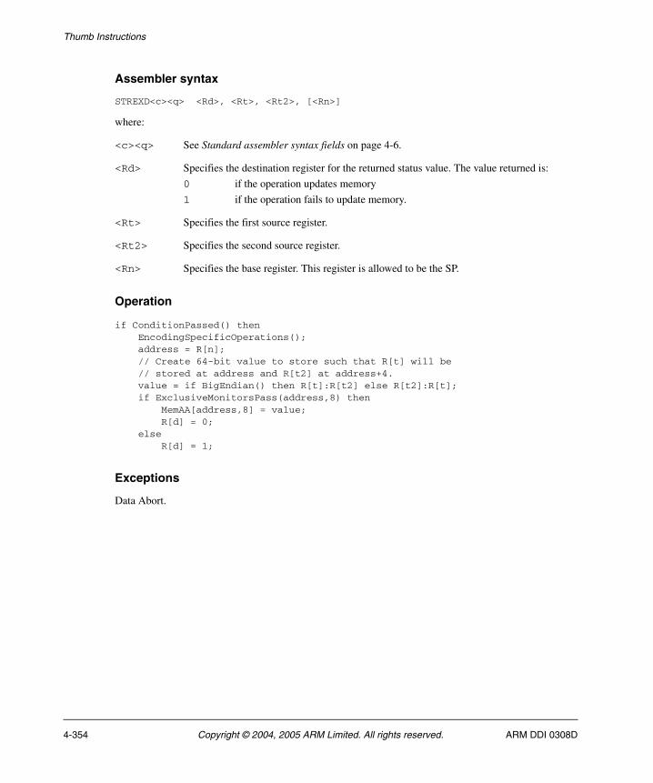
Thumb Instructions
Assembler syntax
STREXD<c><q> <Rd>, <Rt>, <Rt2>, [<Rn>]
where:
<c><q> See Standard assembler syntax fields on page 4-6.
<Rd> Specifies the destination register for the returned status value. The value returned is:
0 if the operation updates memory
1 if the operation fails to update memory.
<Rt> Specifies the first source register.
<Rt2> Specifies the second source register.
<Rn> Specifies the base register. This register is allowed to be the SP.
Operation
if ConditionPassed() then EncodingSpecificOperations(); address = R[n]; // Create 64-bit value to store such that R[t] will be // stored at address and R[t2] at address+4. value = if BigEndian() then R[t]:R[t2] else R[t2]:R[t]; if ExclusiveMonitorsPass(address,8) then MemAA[address,8] = value; R[d] = 0; else R[d] = 1;
Exceptions
Data Abort.
4-354 Copyright © 2004, 2005 ARM Limited. All rights reserved. ARM DDI 0308D

Thumb Instructions
4.6.171 STREXH
Store Register Exclusive Halfword derives an address from a base register value, and stores a halfword from a register to memory if the executing processor has exclusive access to the memory addressed.
See Memory accesses on page 4-13 for information about memory accesses.
Encoding
d = UInt(Rd); t = UInt(Rt); n = UInt(Rn);if BadReg(d) || BadReg(t) || n == 15 then UNPREDICTABLE;if d == n || d == t then UNPREDICTABLE;
Architecture versions
Encoding T1 All versions of the Thumb instruction set from v6K onwards.
T1 STREXH<c> <Rd>,<Rt>,[<Rn>]
15 14 13 12 11 10 9 8 7 6 5 4 3 2 1 0 15 14 13 12 11 10 9 8 7 6 5 4 3 2 1 0
1 1 1 0 1 0 0 0 1 1 0 0 Rn Rt (1) (1) (1) (1) 0 1 0 1 Rd
ARM DDI 0308D Copyright © 2004, 2005 ARM Limited. All rights reserved. 4-355
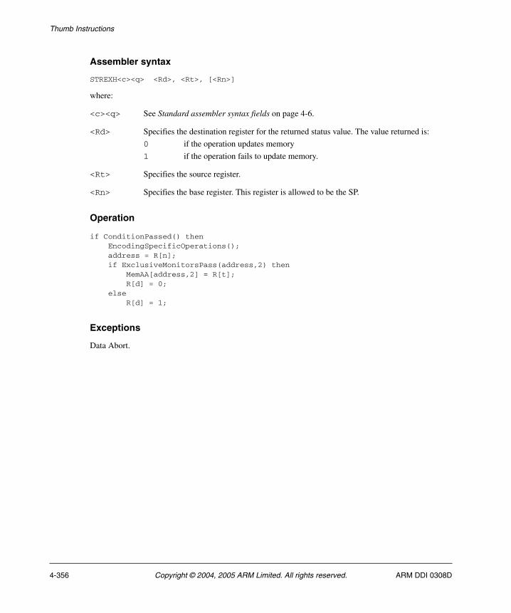
Thumb Instructions
Assembler syntax
STREXH<c><q> <Rd>, <Rt>, [<Rn>]
where:
<c><q> See Standard assembler syntax fields on page 4-6.
<Rd> Specifies the destination register for the returned status value. The value returned is:
0 if the operation updates memory
1 if the operation fails to update memory.
<Rt> Specifies the source register.
<Rn> Specifies the base register. This register is allowed to be the SP.
Operation
if ConditionPassed() then EncodingSpecificOperations(); address = R[n]; if ExclusiveMonitorsPass(address,2) then MemAA[address,2] = R[t]; R[d] = 0; else R[d] = 1;
Exceptions
Data Abort.
4-356 Copyright © 2004, 2005 ARM Limited. All rights reserved. ARM DDI 0308D
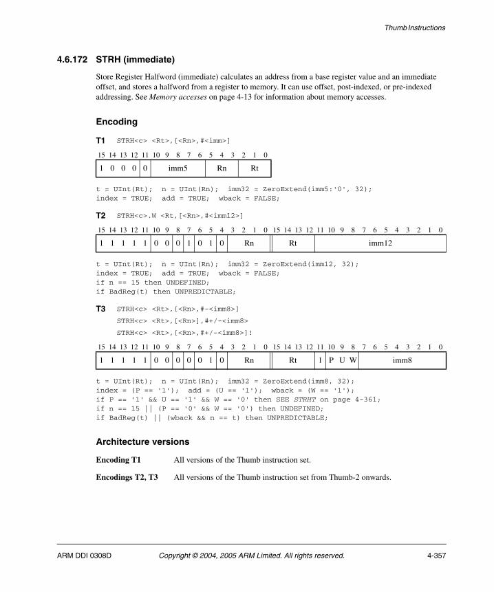
Thumb Instructions
4.6.172 STRH (immediate)
Store Register Halfword (immediate) calculates an address from a base register value and an immediate offset, and stores a halfword from a register to memory. It can use offset, post-indexed, or pre-indexed addressing. See Memory accesses on page 4-13 for information about memory accesses.
Encoding
t = UInt(Rt); n = UInt(Rn); imm32 = ZeroExtend(imm5:'0', 32);index = TRUE; add = TRUE; wback = FALSE;
t = UInt(Rt); n = UInt(Rn); imm32 = ZeroExtend(imm12, 32);index = TRUE; add = TRUE; wback = FALSE;if n == 15 then UNDEFINED;if BadReg(t) then UNPREDICTABLE;
t = UInt(Rt); n = UInt(Rn); imm32 = ZeroExtend(imm8, 32);index = (P == '1'); add = (U == '1'); wback = (W == '1');if P == '1' && U == '1' && W == '0' then SEE STRHT on page 4-361;if n == 15 || (P == '0' && W == '0') then UNDEFINED;if BadReg(t) || (wback && n == t) then UNPREDICTABLE;
Architecture versions
Encoding T1 All versions of the Thumb instruction set.
Encodings T2, T3 All versions of the Thumb instruction set from Thumb-2 onwards.
T1 STRH<c> <Rt>,[<Rn>,#<imm>]
15 14 13 12 11 10 9 8 7 6 5 4 3 2 1 0
1 0 0 0 0 imm5 Rn Rt
T2 STRH<c>.W <Rt,[<Rn>,#<imm12>]
15 14 13 12 11 10 9 8 7 6 5 4 3 2 1 0 15 14 13 12 11 10 9 8 7 6 5 4 3 2 1 0
1 1 1 1 1 0 0 0 1 0 1 0 Rn Rt imm12
T3 STRH<c> <Rt>,[<Rn>,#-<imm8>]
STRH<c> <Rt>,[<Rn>],#+/-<imm8>
STRH<c> <Rt>,[<Rn>,#+/-<imm8>]!
15 14 13 12 11 10 9 8 7 6 5 4 3 2 1 0 15 14 13 12 11 10 9 8 7 6 5 4 3 2 1 0
1 1 1 1 1 0 0 0 0 0 1 0 Rn Rt 1 P U W imm8
ARM DDI 0308D Copyright © 2004, 2005 ARM Limited. All rights reserved. 4-357

Thumb Instructions
Assembler syntax
where:
<c><q> See Standard assembler syntax fields on page 4-6.
<Rt> Specifies the source register.
<Rn> Specifies the base register. This register is allowed to be the SP.
+/- Is + or omitted to indicate that the immediate offset is added to the base register value (add == TRUE), or – to indicate that the offset is to be subtracted (add == FALSE). Different instructions are generated for #0 and #-0.
<imm> Specifies the immediate offset added to or subtracted from the value of <Rn> to form the address. For the offset addressing syntax, <imm> can be omitted, meaning an offset of 0.
The pre-UAL syntax STR<c>H is equivalent to STRH<c>.
Operation
if ConditionPassed() then EncodingSpecificOperations(); offset_addr = if add then (R[n] + imm32) else (R[n] - imm32); address = if index then offset_addr else R[n]; if wback then R[n] = offset_addr; MemU[address,2] = R[t]<15:0>;
Exceptions
Data Abort.
STRH<c><q> <Rt>, [<Rn> {, #+/-<imm>}] Offset: index==TRUE, wback==FALSESTRH<c><q> <Rt>, [<Rn>, #+/-<imm>]! Pre-indexed: index==TRUE, wback==TRUESTRH<c><q> <Rt>, [<Rn>], #+/-<imm> Post-indexed: index==FALSE, wback==TRUE
4-358 Copyright © 2004, 2005 ARM Limited. All rights reserved. ARM DDI 0308D
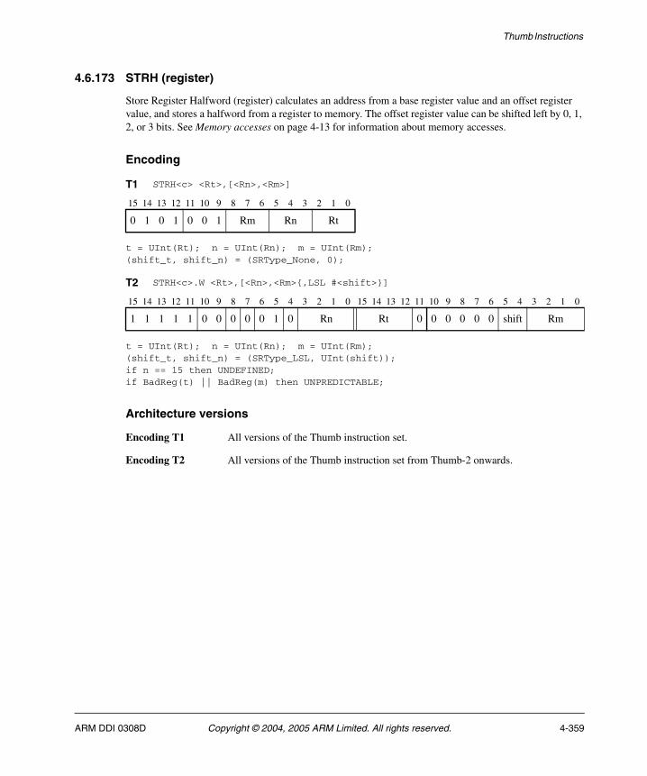
Thumb Instructions
4.6.173 STRH (register)
Store Register Halfword (register) calculates an address from a base register value and an offset register value, and stores a halfword from a register to memory. The offset register value can be shifted left by 0, 1, 2, or 3 bits. See Memory accesses on page 4-13 for information about memory accesses.
Encoding
t = UInt(Rt); n = UInt(Rn); m = UInt(Rm);(shift_t, shift_n) = (SRType_None, 0);
t = UInt(Rt); n = UInt(Rn); m = UInt(Rm);(shift_t, shift_n) = (SRType_LSL, UInt(shift));if n == 15 then UNDEFINED;if BadReg(t) || BadReg(m) then UNPREDICTABLE;
Architecture versions
Encoding T1 All versions of the Thumb instruction set.
Encoding T2 All versions of the Thumb instruction set from Thumb-2 onwards.
T1 STRH<c> <Rt>,[<Rn>,<Rm>]
15 14 13 12 11 10 9 8 7 6 5 4 3 2 1 0
0 1 0 1 0 0 1 Rm Rn Rt
T2 STRH<c>.W <Rt>,[<Rn>,<Rm>{,LSL #<shift>}]
15 14 13 12 11 10 9 8 7 6 5 4 3 2 1 0 15 14 13 12 11 10 9 8 7 6 5 4 3 2 1 0
1 1 1 1 1 0 0 0 0 0 1 0 Rn Rt 0 0 0 0 0 0 shift Rm
ARM DDI 0308D Copyright © 2004, 2005 ARM Limited. All rights reserved. 4-359

Thumb Instructions
Assembler syntax
STRH<c><q> <Rt>, [<Rn>, <Rm> {, LSL #<shift>}]
where:
<c><q> See Standard assembler syntax fields on page 4-6.
<Rn> Specifies the register that contains the base value. This register is allowed to be the SP.
<Rm> Contains the offset that is shifted left and added to the value of <Rn> to form the address.
<shift> Specifies the number of bits the value from <Rm> is shifted left, in the range 0-3. If this option is omitted, a shift by 0 is assumed and both encodings are permitted. If this option is specified, only encoding T2 is permitted.
The pre-UAL syntax STR<c>H is equivalent to STRH<c>.
Operation
if ConditionPassed() then EncodingSpecificOperations(); address = R[n] + LSL(R[m], shift_n); MemU[address,2] = R[t]<15:0>;
Exceptions
Data Abort.
4-360 Copyright © 2004, 2005 ARM Limited. All rights reserved. ARM DDI 0308D
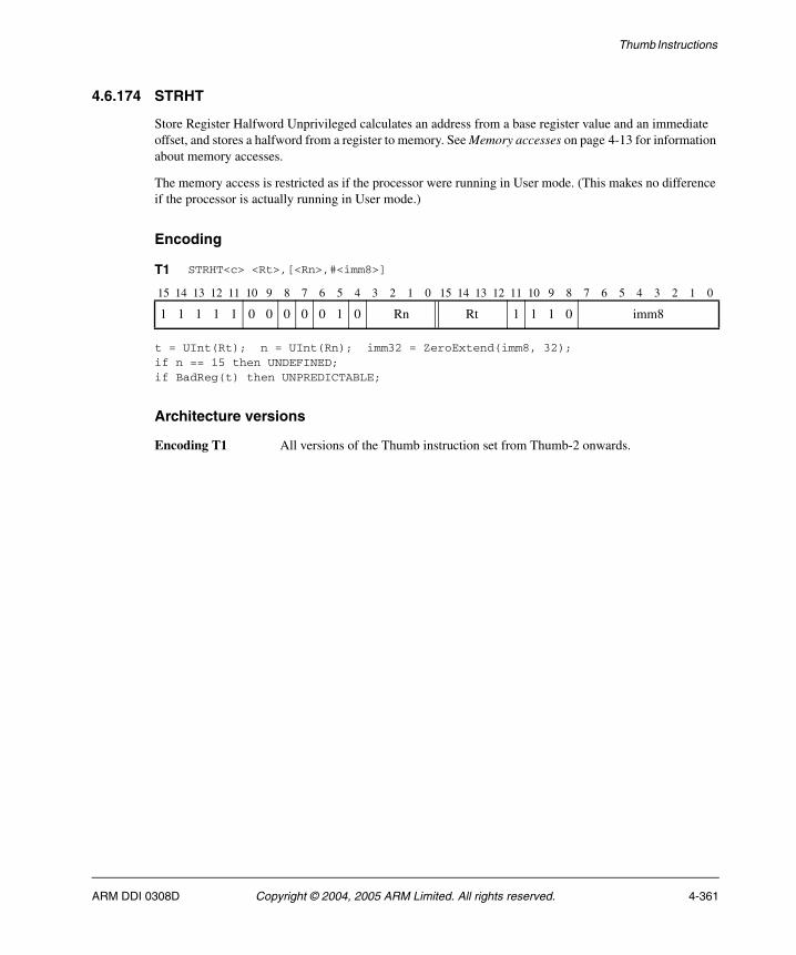
Thumb Instructions
4.6.174 STRHT
Store Register Halfword Unprivileged calculates an address from a base register value and an immediate offset, and stores a halfword from a register to memory. See Memory accesses on page 4-13 for information about memory accesses.
The memory access is restricted as if the processor were running in User mode. (This makes no difference if the processor is actually running in User mode.)
Encoding
t = UInt(Rt); n = UInt(Rn); imm32 = ZeroExtend(imm8, 32);if n == 15 then UNDEFINED;if BadReg(t) then UNPREDICTABLE;
Architecture versions
Encoding T1 All versions of the Thumb instruction set from Thumb-2 onwards.
T1 STRHT<c> <Rt>,[<Rn>,#<imm8>]
15 14 13 12 11 10 9 8 7 6 5 4 3 2 1 0 15 14 13 12 11 10 9 8 7 6 5 4 3 2 1 0
1 1 1 1 1 0 0 0 0 0 1 0 Rn Rt 1 1 1 0 imm8
ARM DDI 0308D Copyright © 2004, 2005 ARM Limited. All rights reserved. 4-361
Thumb Instructions
Assembler syntax
STRHT<c><q> <Rt>, [<Rn> {, #<imm>}]
where:
<c><q> See Standard assembler syntax fields on page 4-6.
<Rt> Specifies the source register.
<Rn> Specifies the base register. This register is allowed to be the SP.
<imm> Specifies the immediate offset added to the value of <Rn> to form the address. <imm> can be omitted, meaning an offset of 0.
Operation
if ConditionPassed() then EncodingSpecificOperations(); address = R[n] + offset; MemU_unpriv[address,2] = R[t]<15:0>;
Exceptions
Data Abort.
4-362 Copyright © 2004, 2005 ARM Limited. All rights reserved. ARM DDI 0308D
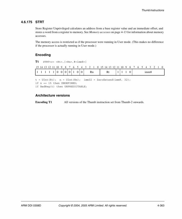
Thumb Instructions
4.6.175 STRT
Store Register Unprivileged calculates an address from a base register value and an immediate offset, and stores a word from a register to memory. See Memory accesses on page 4-13 for information about memory accesses.
The memory access is restricted as if the processor were running in User mode. (This makes no difference if the processor is actually running in User mode.)
Encoding
t = UInt(Rt); n = UInt(Rn); imm32 = ZeroExtend(imm8, 32);if n == 15 then UNDEFINED;if BadReg(t) then UNPREDICTABLE;
Architecture versions
Encoding T1 All versions of the Thumb instruction set from Thumb-2 onwards.
T1 STRT<c> <Rt>,[<Rn>,#<imm8>]
15 14 13 12 11 10 9 8 7 6 5 4 3 2 1 0 15 14 13 12 11 10 9 8 7 6 5 4 3 2 1 0
1 1 1 1 1 0 0 0 0 1 0 0 Rn Rt 1 1 1 0 imm8
ARM DDI 0308D Copyright © 2004, 2005 ARM Limited. All rights reserved. 4-363
Thumb Instructions
Assembler syntax
STRT<c><q> <Rt>, [<Rn> {, #<imm>}]
where:
<c><q> See Standard assembler syntax fields on page 4-6.
<Rt> Specifies the source register.
<Rn> Specifies the base register. This register is allowed to be the SP.
<imm> Specifies the immediate offset added to the value of <Rn> to form the address. <imm> can be omitted, meaning an offset of 0.
The pre-UAL syntax STR<c>T is equivalent to STRT<c>.
Operation
if ConditionPassed() then EncodingSpecificOperations(); address = R[n] + imm32; MemU_unpriv[address,4] = R[t];
Exceptions
Data Abort.
4-364 Copyright © 2004, 2005 ARM Limited. All rights reserved. ARM DDI 0308D
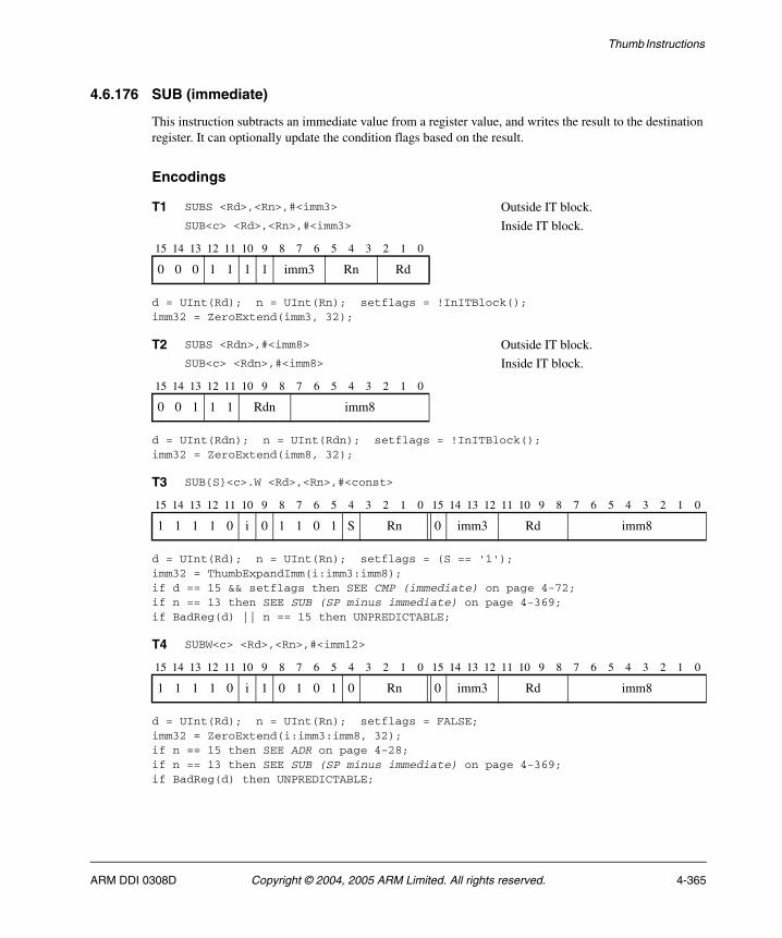
Thumb Instructions
4.6.176 SUB (immediate)
This instruction subtracts an immediate value from a register value, and writes the result to the destination register. It can optionally update the condition flags based on the result.
Encodings
d = UInt(Rd); n = UInt(Rn); setflags = !InITBlock();imm32 = ZeroExtend(imm3, 32);
d = UInt(Rdn); n = UInt(Rdn); setflags = !InITBlock();imm32 = ZeroExtend(imm8, 32);
d = UInt(Rd); n = UInt(Rn); setflags = (S == '1');imm32 = ThumbExpandImm(i:imm3:imm8);if d == 15 && setflags then SEE CMP (immediate) on page 4-72;if n == 13 then SEE SUB (SP minus immediate) on page 4-369;if BadReg(d) || n == 15 then UNPREDICTABLE;
d = UInt(Rd); n = UInt(Rn); setflags = FALSE;imm32 = ZeroExtend(i:imm3:imm8, 32);if n == 15 then SEE ADR on page 4-28;if n == 13 then SEE SUB (SP minus immediate) on page 4-369;if BadReg(d) then UNPREDICTABLE;
T1 SUBS <Rd>,<Rn>,#<imm3> Outside IT block.SUB<c> <Rd>,<Rn>,#<imm3> Inside IT block.
15 14 13 12 11 10 9 8 7 6 5 4 3 2 1 0
0 0 0 1 1 1 1 imm3 Rn Rd
T2 SUBS <Rdn>,#<imm8> Outside IT block.SUB<c> <Rdn>,#<imm8> Inside IT block.
15 14 13 12 11 10 9 8 7 6 5 4 3 2 1 0
0 0 1 1 1 Rdn imm8
T3 SUB{S}<c>.W <Rd>,<Rn>,#<const>
15 14 13 12 11 10 9 8 7 6 5 4 3 2 1 0 15 14 13 12 11 10 9 8 7 6 5 4 3 2 1 0
1 1 1 1 0 i 0 1 1 0 1 S Rn 0 imm3 Rd imm8
T4 SUBW<c> <Rd>,<Rn>,#<imm12>
15 14 13 12 11 10 9 8 7 6 5 4 3 2 1 0 15 14 13 12 11 10 9 8 7 6 5 4 3 2 1 0
1 1 1 1 0 i 1 0 1 0 1 0 Rn 0 imm3 Rd imm8
ARM DDI 0308D Copyright © 2004, 2005 ARM Limited. All rights reserved. 4-365
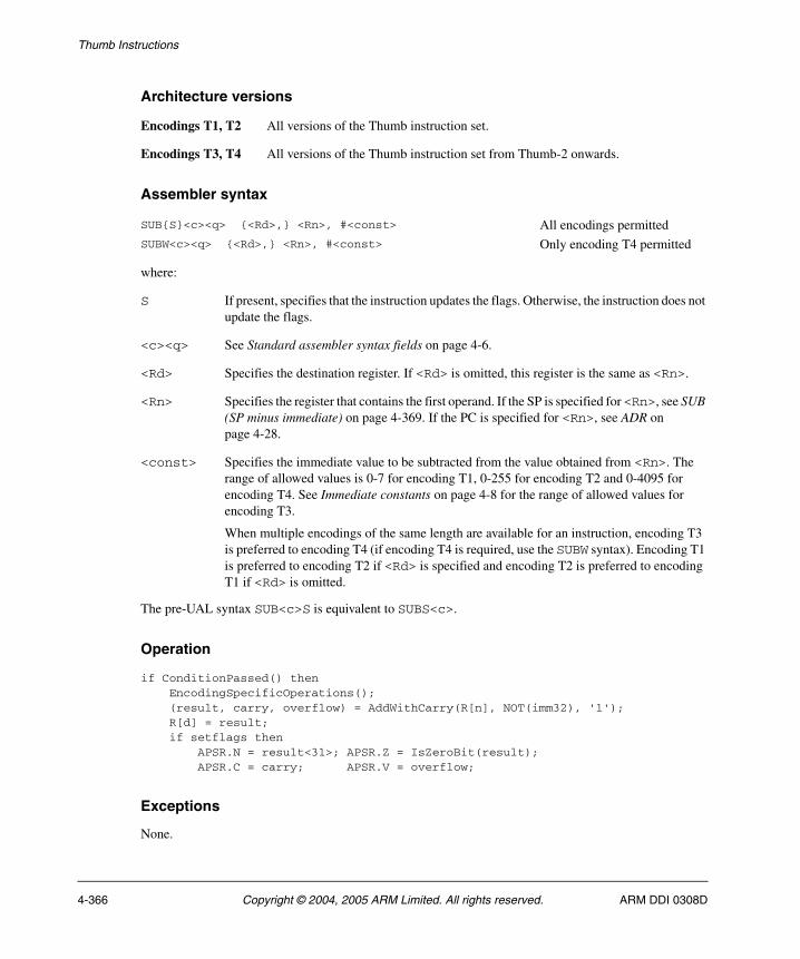
Thumb Instructions
Architecture versions
Encodings T1, T2 All versions of the Thumb instruction set.
Encodings T3, T4 All versions of the Thumb instruction set from Thumb-2 onwards.
Assembler syntax
where:
S If present, specifies that the instruction updates the flags. Otherwise, the instruction does not update the flags.
<c><q> See Standard assembler syntax fields on page 4-6.
<Rd> Specifies the destination register. If <Rd> is omitted, this register is the same as <Rn>.
<Rn> Specifies the register that contains the first operand. If the SP is specified for <Rn>, see SUB (SP minus immediate) on page 4-369. If the PC is specified for <Rn>, see ADR on page 4-28.
<const> Specifies the immediate value to be subtracted from the value obtained from <Rn>. The range of allowed values is 0-7 for encoding T1, 0-255 for encoding T2 and 0-4095 for encoding T4. See Immediate constants on page 4-8 for the range of allowed values for encoding T3.
When multiple encodings of the same length are available for an instruction, encoding T3 is preferred to encoding T4 (if encoding T4 is required, use the SUBW syntax). Encoding T1 is preferred to encoding T2 if <Rd> is specified and encoding T2 is preferred to encoding T1 if <Rd> is omitted.
The pre-UAL syntax SUB<c>S is equivalent to SUBS<c>.
Operation
if ConditionPassed() then EncodingSpecificOperations(); (result, carry, overflow) = AddWithCarry(R[n], NOT(imm32), '1'); R[d] = result; if setflags then APSR.N = result<31>; APSR.Z = IsZeroBit(result); APSR.C = carry; APSR.V = overflow;
Exceptions
None.
SUB{S}<c><q> {<Rd>,} <Rn>, #<const> All encodings permittedSUBW<c><q> {<Rd>,} <Rn>, #<const> Only encoding T4 permitted
4-366 Copyright © 2004, 2005 ARM Limited. All rights reserved. ARM DDI 0308D

Thumb Instructions
4.6.177 SUB (register)
This instruction subtracts an optionally-shifted register value from a register value, and writes the result to the destination register. It can optionally update the condition flags based on the result.
Encodings
d = UInt(Rd); n = UInt(Rn); m = UInt(Rm); setflags = !InITBlock();(shift_t, shift_n) = (SRType_None, 0);
d = UInt(Rd); n = UInt(Rn); m = UInt(Rm); setflags = (S == '1');(shift_t, shift_n) = DecodeImmShift(type, imm3:imm2);if d == 15 && setflags then SEE CMP (register) on page 4-74;if n == 13 then SEE SUB (SP minus register) on page 4-371;if BadReg(d) || n == 15 || BadReg(m) then UNPREDICTABLE;
Architecture versions
Encoding T1 All versions of the Thumb instruction set.
Encoding T2 All versions of the Thumb instruction set from Thumb-2 onwards.
T1 SUBS <Rd>,<Rn>,<Rm> Outside IT block.SUB<c> <Rd>,<Rn>,<Rm> Inside IT block.
15 14 13 12 11 10 9 8 7 6 5 4 3 2 1 0
0 0 0 1 1 0 1 Rm Rn Rd
T2 SUB{S}<c>.W <Rd>,<Rn>,<Rm>{,<shift>}
15 14 13 12 11 10 9 8 7 6 5 4 3 2 1 0 15 14 13 12 11 10 9 8 7 6 5 4 3 2 1 0
1 1 1 0 1 0 1 1 1 0 1 S Rn (0) imm3 Rd imm2 type Rm
ARM DDI 0308D Copyright © 2004, 2005 ARM Limited. All rights reserved. 4-367
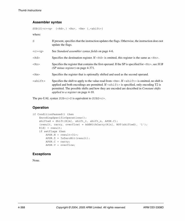
Thumb Instructions
Assembler syntax
SUB{S}<c><q> {<Rd>,} <Rn>, <Rm> {,<shift>}
where:
S If present, specifies that the instruction updates the flags. Otherwise, the instruction does not update the flags.
<c><q> See Standard assembler syntax fields on page 4-6.
<Rd> Specifies the destination register. If <Rd> is omitted, this register is the same as <Rn>.
<Rn> Specifies the register that contains the first operand. If the SP is specified for <Rn>, see SUB (SP minus register) on page 4-371.
<Rm> Specifies the register that is optionally shifted and used as the second operand.
<shift> Specifies the shift to apply to the value read from <Rm>. If <shift> is omitted, no shift is applied and both encodings are permitted. If <shift> is specified, only encoding T2 is permitted. The possible shifts and how they are encoded are described in Constant shifts applied to a register on page 4-10.
The pre-UAL syntax SUB<c>S is equivalent to SUBS<c>.
Operation
if ConditionPassed() then EncodingSpecificOperations(); shifted = Shift(R[m], shift_t, shift_n, APSR.C); (result, carry, overflow) = AddWithCarry(R[n], NOT(shifted), '1'); R[d] = result; if setflags then APSR.N = result<31>; APSR.Z = IsZeroBit(result); APSR.C = carry; APSR.V = overflow;
Exceptions
None.
4-368 Copyright © 2004, 2005 ARM Limited. All rights reserved. ARM DDI 0308D
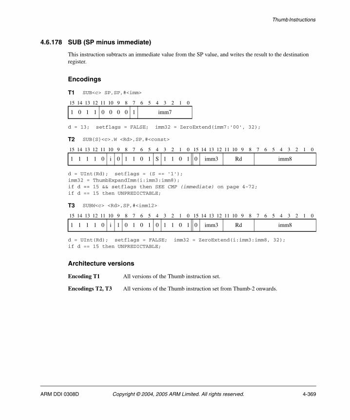
Thumb Instructions
4.6.178 SUB (SP minus immediate)
This instruction subtracts an immediate value from the SP value, and writes the result to the destination register.
Encodings
d = 13; setflags = FALSE; imm32 = ZeroExtend(imm7:'00', 32);
d = UInt(Rd); setflags = (S == '1');imm32 = ThumbExpandImm(i:imm3:imm8);if d == 15 && setflags then SEE CMP (immediate) on page 4-72;if d == 15 then UNPREDICTABLE;
d = UInt(Rd); setflags = FALSE; imm32 = ZeroExtend(i:imm3:imm8, 32);if d == 15 then UNPREDICTABLE;
Architecture versions
Encoding T1 All versions of the Thumb instruction set.
Encodings T2, T3 All versions of the Thumb instruction set from Thumb-2 onwards.
T1 SUB<c> SP,SP,#<imm>
15 14 13 12 11 10 9 8 7 6 5 4 3 2 1 0
1 0 1 1 0 0 0 0 1 imm7
T2 SUB{S}<c>.W <Rd>,SP,#<const>
15 14 13 12 11 10 9 8 7 6 5 4 3 2 1 0 15 14 13 12 11 10 9 8 7 6 5 4 3 2 1 0
1 1 1 1 0 i 0 1 1 0 1 S 1 1 0 1 0 imm3 Rd imm8
T3 SUBW<c> <Rd>,SP,#<imm12>
15 14 13 12 11 10 9 8 7 6 5 4 3 2 1 0 15 14 13 12 11 10 9 8 7 6 5 4 3 2 1 0
1 1 1 1 0 i 1 0 1 0 1 0 1 1 0 1 0 imm3 Rd imm8
ARM DDI 0308D Copyright © 2004, 2005 ARM Limited. All rights reserved. 4-369
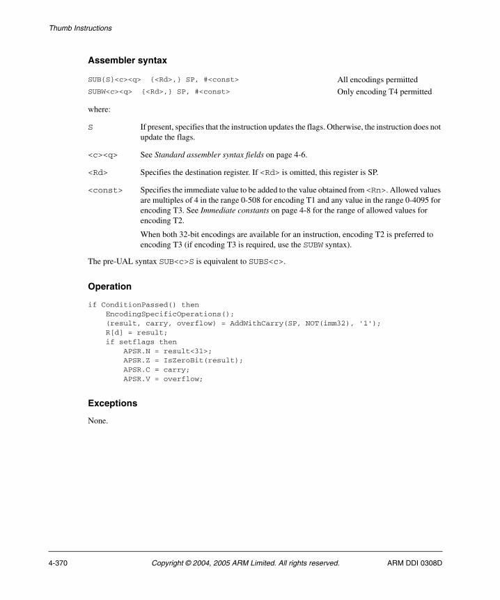
Thumb Instructions
Assembler syntax
where:
S If present, specifies that the instruction updates the flags. Otherwise, the instruction does not update the flags.
<c><q> See Standard assembler syntax fields on page 4-6.
<Rd> Specifies the destination register. If <Rd> is omitted, this register is SP.
<const> Specifies the immediate value to be added to the value obtained from <Rn>. Allowed values are multiples of 4 in the range 0-508 for encoding T1 and any value in the range 0-4095 for encoding T3. See Immediate constants on page 4-8 for the range of allowed values for encoding T2.
When both 32-bit encodings are available for an instruction, encoding T2 is preferred to encoding T3 (if encoding T3 is required, use the SUBW syntax).
The pre-UAL syntax SUB<c>S is equivalent to SUBS<c>.
Operation
if ConditionPassed() then EncodingSpecificOperations(); (result, carry, overflow) = AddWithCarry(SP, NOT(imm32), '1'); R[d] = result; if setflags then APSR.N = result<31>; APSR.Z = IsZeroBit(result); APSR.C = carry; APSR.V = overflow;
Exceptions
None.
SUB{S}<c><q> {<Rd>,} SP, #<const> All encodings permittedSUBW<c><q> {<Rd>,} SP, #<const> Only encoding T4 permitted
4-370 Copyright © 2004, 2005 ARM Limited. All rights reserved. ARM DDI 0308D
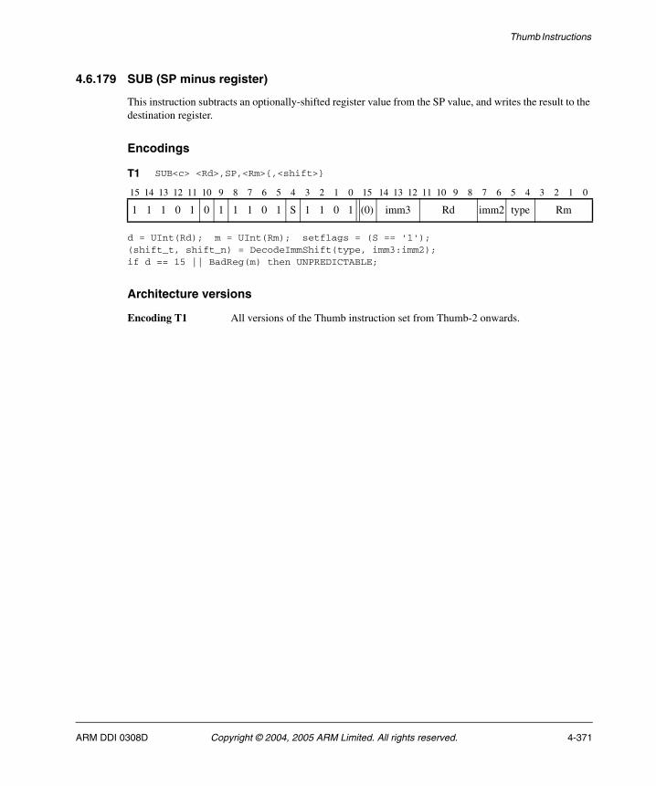
Thumb Instructions
4.6.179 SUB (SP minus register)
This instruction subtracts an optionally-shifted register value from the SP value, and writes the result to the destination register.
Encodings
d = UInt(Rd); m = UInt(Rm); setflags = (S == '1');(shift_t, shift_n) = DecodeImmShift(type, imm3:imm2);if d == 15 || BadReg(m) then UNPREDICTABLE;
Architecture versions
Encoding T1 All versions of the Thumb instruction set from Thumb-2 onwards.
T1 SUB<c> <Rd>,SP,<Rm>{,<shift>}
15 14 13 12 11 10 9 8 7 6 5 4 3 2 1 0 15 14 13 12 11 10 9 8 7 6 5 4 3 2 1 0
1 1 1 0 1 0 1 1 1 0 1 S 1 1 0 1 (0) imm3 Rd imm2 type Rm
ARM DDI 0308D Copyright © 2004, 2005 ARM Limited. All rights reserved. 4-371

Thumb Instructions
Assembler syntax
SUB{S}<c><q> {<Rd>,} SP, <Rm> {,<shift>}
where:
S If present, specifies that the instruction updates the flags. Otherwise, the instruction does not update the flags.
<c><q> See Standard assembler syntax fields on page 4-6.
<Rd> Specifies the destination register. If <Rd> is omitted, this register is SP.
<Rm> Specifies the register that is optionally shifted and used as the second operand.
<shift> Specifies the shift to apply to the value read from <Rm>. If <shift> is omitted, no shift is applied. The possible shifts and how they are encoded are described in Constant shifts applied to a register on page 4-10.
The pre-UAL syntax SUB<c>S is equivalent to SUBS<c>.
Operation
if ConditionPassed() then EncodingSpecificOperations(); shifted = Shift(R[m], shift_t, shift_n, APSR.C); (result, carry, overflow) = AddWithCarry(SP, NOT(shifted), '1'); R[d] = result; if setflags then APSR.N = result<31>; APSR.Z = IsZeroBit(result); APSR.C = carry; APSR.V = overflow;
Exceptions
None.
4-372 Copyright © 2004, 2005 ARM Limited. All rights reserved. ARM DDI 0308D
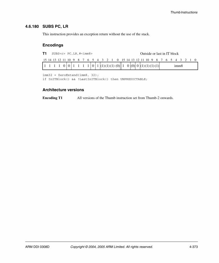
Thumb Instructions
4.6.180 SUBS PC, LR
This instruction provides an exception return without the use of the stack.
Encodings
imm32 = ZeroExtend(imm8, 32);if InITBlock() && !LastInITBlock() then UNPREDICTABLE;
Architecture versions
Encoding T1 All versions of the Thumb instruction set from Thumb-2 onwards.
T1 SUBS<c> PC,LR,#<imm8> Outside or last in IT block
15 14 13 12 11 10 9 8 7 6 5 4 3 2 1 0 15 14 13 12 11 10 9 8 7 6 5 4 3 2 1 0
1 1 1 1 0 0 1 1 1 1 0 1 (1) (1) (1) (0) 1 0 (0) 0 (1) (1) (1) (1) imm8
ARM DDI 0308D Copyright © 2004, 2005 ARM Limited. All rights reserved. 4-373
Thumb Instructions
Assembler syntax
SUBS<c><q> PC, LR, #<imm>
where:
<c><q> See Standard assembler syntax fields on page 4-6.
<imm> Specifies an 8-bit immediate constant.
The pre-UAL syntax SUB<c>S is equivalent to SUBS<c>.
Operation
if ConditionPassed() then EncodingSpecificOperations(); BranchWritePC(LR - imm32); CPSR = SPSR;
Exceptions
None.
4-374 Copyright © 2004, 2005 ARM Limited. All rights reserved. ARM DDI 0308D
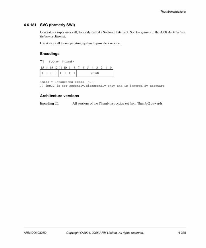
Thumb Instructions
4.6.181 SVC (formerly SWI)
Generates a supervisor call, formerly called a Software Interrupt. See Exceptions in the ARM Architecture Reference Manual.
Use it as a call to an operating system to provide a service.
Encodings
imm32 = ZeroExtend(imm24, 32);// imm32 is for assembly/disassembly only and is ignored by hardware
Architecture versions
Encoding T1 All versions of the Thumb instruction set from Thumb-2 onwards.
T1 SVC<c> #<imm8>
15 14 13 12 11 10 9 8 7 6 5 4 3 2 1 0
1 1 0 1 1 1 1 1 imm8
ARM DDI 0308D Copyright © 2004, 2005 ARM Limited. All rights reserved. 4-375
Thumb Instructions
Assembler syntax
SVC<c><q> #<imm>
where:
<c><q> See Standard assembler syntax fields on page 4-6.
<imm> Specifies an 8-bit immediate constant.
The pre-UAL syntax SWI<c> is equivalent to SVC<c>.
Operation
if ConditionPassed() then EncodingSpecificOperations(); CallSupervisor();
Exceptions
None.
4-376 Copyright © 2004, 2005 ARM Limited. All rights reserved. ARM DDI 0308D
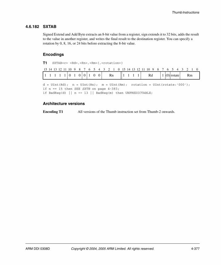
Thumb Instructions
4.6.182 SXTAB
Signed Extend and Add Byte extracts an 8-bit value from a register, sign extends it to 32 bits, adds the result to the value in another register, and writes the final result to the destination register. You can specify a rotation by 0, 8, 16, or 24 bits before extracting the 8-bit value.
Encodings
d = UInt(Rd); n = UInt(Rn); m = UInt(Rm); rotation = UInt(rotate:'000');if n == 15 then SEE SXTB on page 4-383;if BadReg(d) || n == 13 || BadReg(m) then UNPREDICTABLE;
Architecture versions
Encoding T1 All versions of the Thumb instruction set from Thumb-2 onwards.
T1 SXTAB<c> <Rd>,<Rn>,<Rm>{,<rotation>}
15 14 13 12 11 10 9 8 7 6 5 4 3 2 1 0 15 14 13 12 11 10 9 8 7 6 5 4 3 2 1 0
1 1 1 1 1 0 1 0 0 1 0 0 Rn 1 1 1 1 Rd 1 (0) rotate Rm
ARM DDI 0308D Copyright © 2004, 2005 ARM Limited. All rights reserved. 4-377

Thumb Instructions
Assembler syntax
SXTAB<c><q> {<Rd>,} <Rn>, <Rm> {, <rotation>}
where:
<c><q> See Standard assembler syntax fields on page 4-6.
<Rd> Specifies the destination register. If <Rd> is omitted, this register is the same as <Rn>.
<Rn> Specifies the register that contains the first operand.
<Rm> Specifies the register that contains the second operand.
<rotation>
This can be any one of:
• ROR #8.
• ROR #16.
• ROR #24.
• Omitted.
Note If your assembler accepts shifts by #0 and treats them as equivalent to no shift or LSL
#0, then it must accept ROR #0 here. It is equivalent to omitting <rotation>.
Operation
if ConditionPassed() then EncodingSpecificOperations(); rotated = ROR(R[m], rotation); R[d] = R[n] + SignExtend(rotated<7:0>, 32);
Exceptions
None.
4-378 Copyright © 2004, 2005 ARM Limited. All rights reserved. ARM DDI 0308D
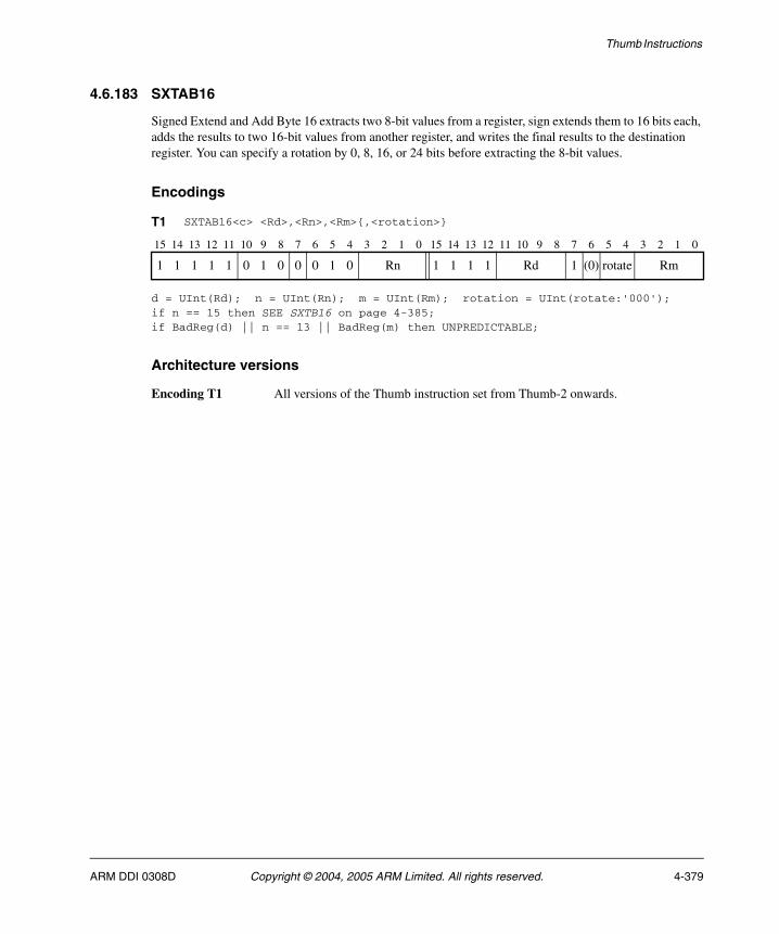
Thumb Instructions
4.6.183 SXTAB16
Signed Extend and Add Byte 16 extracts two 8-bit values from a register, sign extends them to 16 bits each, adds the results to two 16-bit values from another register, and writes the final results to the destination register. You can specify a rotation by 0, 8, 16, or 24 bits before extracting the 8-bit values.
Encodings
d = UInt(Rd); n = UInt(Rn); m = UInt(Rm); rotation = UInt(rotate:'000');if n == 15 then SEE SXTB16 on page 4-385;if BadReg(d) || n == 13 || BadReg(m) then UNPREDICTABLE;
Architecture versions
Encoding T1 All versions of the Thumb instruction set from Thumb-2 onwards.
T1 SXTAB16<c> <Rd>,<Rn>,<Rm>{,<rotation>}
15 14 13 12 11 10 9 8 7 6 5 4 3 2 1 0 15 14 13 12 11 10 9 8 7 6 5 4 3 2 1 0
1 1 1 1 1 0 1 0 0 0 1 0 Rn 1 1 1 1 Rd 1 (0) rotate Rm
ARM DDI 0308D Copyright © 2004, 2005 ARM Limited. All rights reserved. 4-379
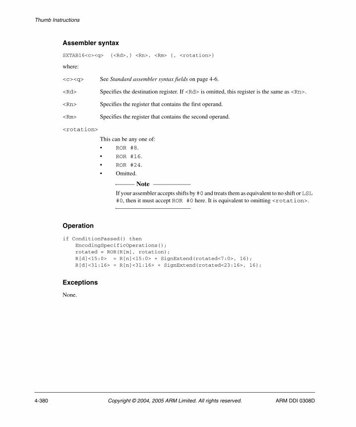
Thumb Instructions
Assembler syntax
SXTAB16<c><q> {<Rd>,} <Rn>, <Rm> {, <rotation>}
where:
<c><q> See Standard assembler syntax fields on page 4-6.
<Rd> Specifies the destination register. If <Rd> is omitted, this register is the same as <Rn>.
<Rn> Specifies the register that contains the first operand.
<Rm> Specifies the register that contains the second operand.
<rotation>
This can be any one of:
• ROR #8.
• ROR #16.
• ROR #24.
• Omitted.
Note If your assembler accepts shifts by #0 and treats them as equivalent to no shift or LSL
#0, then it must accept ROR #0 here. It is equivalent to omitting <rotation>.
Operation
if ConditionPassed() then EncodingSpecificOperations(); rotated = ROR(R[m], rotation); R[d]<15:0> = R[n]<15:0> + SignExtend(rotated<7:0>, 16); R[d]<31:16> = R[n]<31:16> + SignExtend(rotated<23:16>, 16);
Exceptions
None.
4-380 Copyright © 2004, 2005 ARM Limited. All rights reserved. ARM DDI 0308D
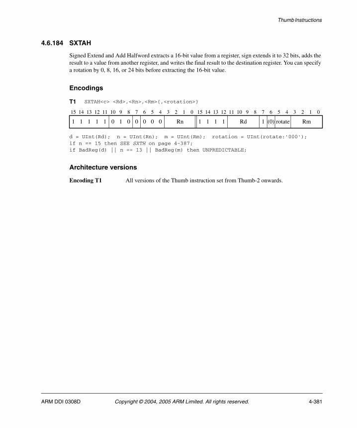
Thumb Instructions
4.6.184 SXTAH
Signed Extend and Add Halfword extracts a 16-bit value from a register, sign extends it to 32 bits, adds the result to a value from another register, and writes the final result to the destination register. You can specify a rotation by 0, 8, 16, or 24 bits before extracting the 16-bit value.
Encodings
d = UInt(Rd); n = UInt(Rn); m = UInt(Rm); rotation = UInt(rotate:'000');if n == 15 then SEE SXTH on page 4-387;if BadReg(d) || n == 13 || BadReg(m) then UNPREDICTABLE;
Architecture versions
Encoding T1 All versions of the Thumb instruction set from Thumb-2 onwards.
T1 SXTAH<c> <Rd>,<Rn>,<Rm>{,<rotation>}
15 14 13 12 11 10 9 8 7 6 5 4 3 2 1 0 15 14 13 12 11 10 9 8 7 6 5 4 3 2 1 0
1 1 1 1 1 0 1 0 0 0 0 0 Rn 1 1 1 1 Rd 1 (0) rotate Rm
ARM DDI 0308D Copyright © 2004, 2005 ARM Limited. All rights reserved. 4-381

Thumb Instructions
Assembler syntax
SXTAH<c><q> {<Rd>,} <Rn>, <Rm> {, <rotation>}
where:
<c><q> See Standard assembler syntax fields on page 4-6.
<Rd> Specifies the destination register. If <Rd> is omitted, this register is the same as <Rn>.
<Rn> Specifies the register that contains the first operand.
<Rm> Specifies the register that contains the second operand.
<rotation>
This can be any one of:
• ROR #8.
• ROR #16.
• ROR #24.
• Omitted.
Note If your assembler accepts shifts by #0 and treats them as equivalent to no shift or LSL
#0, then it must accept ROR #0 here. It is equivalent to omitting <rotation>.
Operation
if ConditionPassed() then EncodingSpecificOperations(); rotated = ROR(R[m], rotation); R[d] = R[n] + SignExtend(rotated<15:0>, 32);
Exceptions
None.
4-382 Copyright © 2004, 2005 ARM Limited. All rights reserved. ARM DDI 0308D
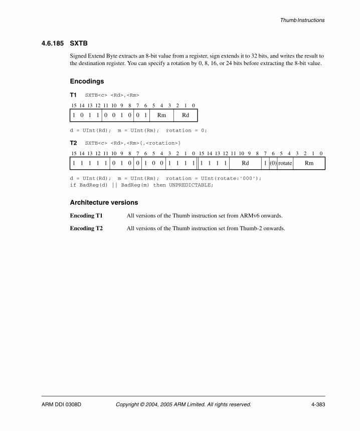
Thumb Instructions
4.6.185 SXTB
Signed Extend Byte extracts an 8-bit value from a register, sign extends it to 32 bits, and writes the result to the destination register. You can specify a rotation by 0, 8, 16, or 24 bits before extracting the 8-bit value.
Encodings
d = UInt(Rd); m = UInt(Rm); rotation = 0;
d = UInt(Rd); m = UInt(Rm); rotation = UInt(rotate:'000');if BadReg(d) || BadReg(m) then UNPREDICTABLE;
Architecture versions
Encoding T1 All versions of the Thumb instruction set from ARMv6 onwards.
Encoding T2 All versions of the Thumb instruction set from Thumb-2 onwards.
T1 SXTB<c> <Rd>,<Rm>
15 14 13 12 11 10 9 8 7 6 5 4 3 2 1 0
1 0 1 1 0 0 1 0 0 1 Rm Rd
T2 SXTB<c> <Rd>,<Rm>{,<rotation>}
15 14 13 12 11 10 9 8 7 6 5 4 3 2 1 0 15 14 13 12 11 10 9 8 7 6 5 4 3 2 1 0
1 1 1 1 1 0 1 0 0 1 0 0 1 1 1 1 1 1 1 1 Rd 1 (0) rotate Rm
ARM DDI 0308D Copyright © 2004, 2005 ARM Limited. All rights reserved. 4-383

Thumb Instructions
Assembler syntax
SXTB<c><q> <Rd>, <Rm> {, <rotation>}
where:
<c><q> See Standard assembler syntax fields on page 4-6.
<Rd> Specifies the destination register.
<Rm> Specifies the register that contains the operand.
<rotation>
This can be any one of:
• ROR #8.
• ROR #16.
• ROR #24.
• Omitted.
Note If your assembler accepts shifts by #0 and treats them as equivalent to no shift or LSL
#0, then it must accept ROR #0 here. It is equivalent to omitting <rotation>.
Operation
if ConditionPassed() then EncodingSpecificOperations(); rotated = ROR(R[m], rotation); R[d] = SignExtend(rotated<7:0>, 32);
Exceptions
None.
4-384 Copyright © 2004, 2005 ARM Limited. All rights reserved. ARM DDI 0308D

Thumb Instructions
4.6.186 SXTB16
Signed Extend Byte 16 extracts two 8-bit values from a register, sign extends them to 16 bits each, and writes the results to the destination register. You can specify a rotation by 0, 8, 16, or 24 bits before extracting the 8-bit values.
Encodings
d = UInt(Rd); m = UInt(Rm); rotation = UInt(rotate:'000');if BadReg(d) || BadReg(m) then UNPREDICTABLE;
Architecture versions
Encoding T1 All versions of the Thumb instruction set from Thumb-2 onwards.
T1 SXTB16<c> <Rd>,<Rm>{,<rotation>}
15 14 13 12 11 10 9 8 7 6 5 4 3 2 1 0 15 14 13 12 11 10 9 8 7 6 5 4 3 2 1 0
1 1 1 1 1 0 1 0 0 0 1 0 1 1 1 1 1 1 1 1 Rd 1 (0) rotate Rm
ARM DDI 0308D Copyright © 2004, 2005 ARM Limited. All rights reserved. 4-385
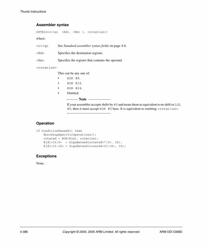
Thumb Instructions
Assembler syntax
SXTB16<c><q> <Rd>, <Rm> {, <rotation>}
where:
<c><q> See Standard assembler syntax fields on page 4-6.
<Rd> Specifies the destination register.
<Rm> Specifies the register that contains the operand.
<rotation>
This can be any one of:
• ROR #8.
• ROR #16.
• ROR #24.
• Omitted.
Note If your assembler accepts shifts by #0 and treats them as equivalent to no shift or LSL
#0, then it must accept ROR #0 here. It is equivalent to omitting <rotation>.
Operation
if ConditionPassed() then EncodingSpecificOperations(); rotated = ROR(R[m], rotation); R[d]<15:0> = SignExtend(rotated<7:0>, 16); R[d]<31:16> = SignExtend(rotated<23:16>, 16);
Exceptions
None.
4-386 Copyright © 2004, 2005 ARM Limited. All rights reserved. ARM DDI 0308D
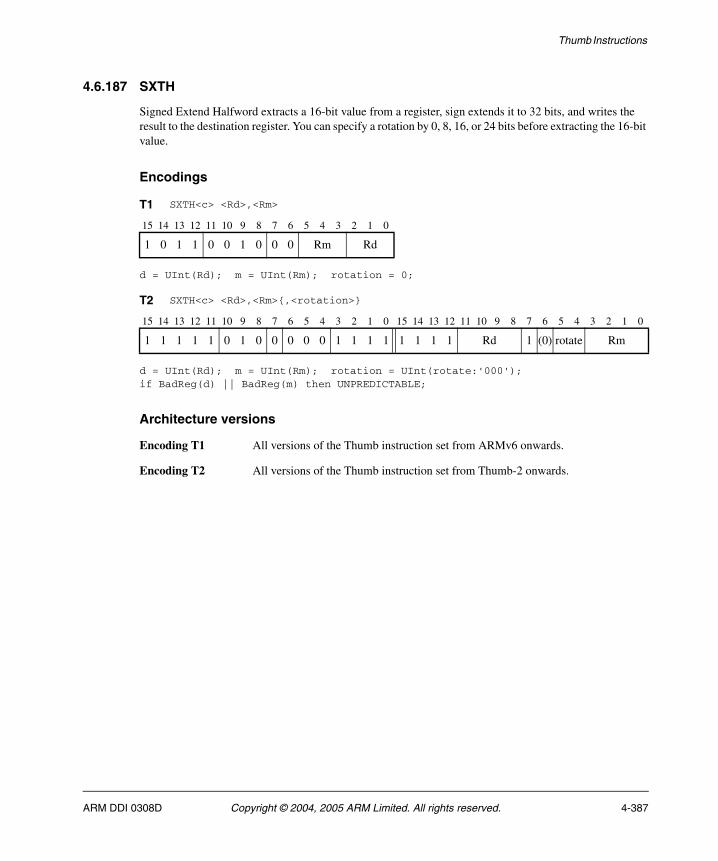
Thumb Instructions
4.6.187 SXTH
Signed Extend Halfword extracts a 16-bit value from a register, sign extends it to 32 bits, and writes the result to the destination register. You can specify a rotation by 0, 8, 16, or 24 bits before extracting the 16-bit value.
Encodings
d = UInt(Rd); m = UInt(Rm); rotation = 0;
d = UInt(Rd); m = UInt(Rm); rotation = UInt(rotate:'000');if BadReg(d) || BadReg(m) then UNPREDICTABLE;
Architecture versions
Encoding T1 All versions of the Thumb instruction set from ARMv6 onwards.
Encoding T2 All versions of the Thumb instruction set from Thumb-2 onwards.
T1 SXTH<c> <Rd>,<Rm>
15 14 13 12 11 10 9 8 7 6 5 4 3 2 1 0
1 0 1 1 0 0 1 0 0 0 Rm Rd
T2 SXTH<c> <Rd>,<Rm>{,<rotation>}
15 14 13 12 11 10 9 8 7 6 5 4 3 2 1 0 15 14 13 12 11 10 9 8 7 6 5 4 3 2 1 0
1 1 1 1 1 0 1 0 0 0 0 0 1 1 1 1 1 1 1 1 Rd 1 (0) rotate Rm
ARM DDI 0308D Copyright © 2004, 2005 ARM Limited. All rights reserved. 4-387

Thumb Instructions
Assembler syntax
SXTH<c><q> <Rd>, <Rm> {, <rotation>}
where:
<c><q> See Standard assembler syntax fields on page 4-6.
<Rd> Specifies the destination register.
<Rm> Specifies the register that contains the operand.
<rotation>
This can be any one of:
• ROR #8.
• ROR #16.
• ROR #24.
• Omitted.
Note If your assembler accepts shifts by #0 and treats them as equivalent to no shift or LSL
#0, then it must accept ROR #0 here. It is equivalent to omitting <rotation>.
Operation
if ConditionPassed() then EncodingSpecificOperations(); rotated = ROR(R[m], rotation); R[d] = SignExtend(rotated<15:0>, 32);
Exceptions
None.
4-388 Copyright © 2004, 2005 ARM Limited. All rights reserved. ARM DDI 0308D
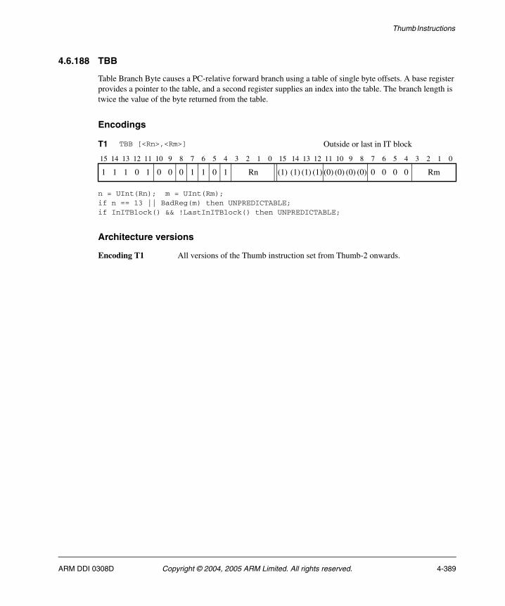
Thumb Instructions
4.6.188 TBB
Table Branch Byte causes a PC-relative forward branch using a table of single byte offsets. A base register provides a pointer to the table, and a second register supplies an index into the table. The branch length is twice the value of the byte returned from the table.
Encodings
n = UInt(Rn); m = UInt(Rm);if n == 13 || BadReg(m) then UNPREDICTABLE;if InITBlock() && !LastInITBlock() then UNPREDICTABLE;
Architecture versions
Encoding T1 All versions of the Thumb instruction set from Thumb-2 onwards.
T1 TBB [<Rn>,<Rm>] Outside or last in IT block
15 14 13 12 11 10 9 8 7 6 5 4 3 2 1 0 15 14 13 12 11 10 9 8 7 6 5 4 3 2 1 0
1 1 1 0 1 0 0 0 1 1 0 1 Rn (1) (1) (1) (1) (0) (0) (0) (0) 0 0 0 0 Rm
ARM DDI 0308D Copyright © 2004, 2005 ARM Limited. All rights reserved. 4-389
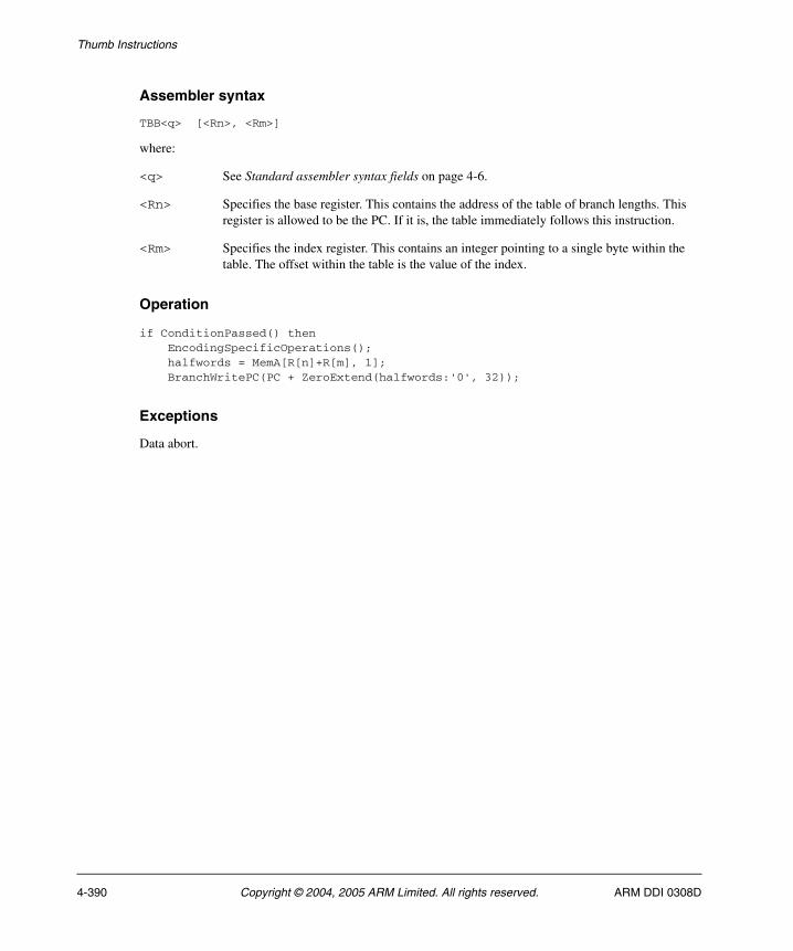
Thumb Instructions
Assembler syntax
TBB<q> [<Rn>, <Rm>]
where:
<q> See Standard assembler syntax fields on page 4-6.
<Rn> Specifies the base register. This contains the address of the table of branch lengths. This register is allowed to be the PC. If it is, the table immediately follows this instruction.
<Rm> Specifies the index register. This contains an integer pointing to a single byte within the table. The offset within the table is the value of the index.
Operation
if ConditionPassed() then EncodingSpecificOperations(); halfwords = MemA[R[n]+R[m], 1]; BranchWritePC(PC + ZeroExtend(halfwords:'0', 32));
Exceptions
Data abort.
4-390 Copyright © 2004, 2005 ARM Limited. All rights reserved. ARM DDI 0308D
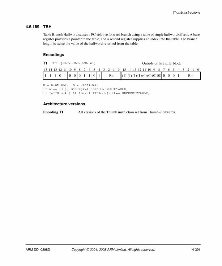
Thumb Instructions
4.6.189 TBH
Table Branch Halfword causes a PC-relative forward branch using a table of single halfword offsets. A base register provides a pointer to the table, and a second register supplies an index into the table. The branch length is twice the value of the halfword returned from the table.
Encodings
n = UInt(Rn); m = UInt(Rm);if n == 13 || BadReg(m) then UNPREDICTABLE;if InITBlock() && !LastInITBlock() then UNPREDICTABLE;
Architecture versions
Encoding T1 All versions of the Thumb instruction set from Thumb-2 onwards.
T1 TBH [<Rn>,<Rm>,LSL #1] Outside or last in IT block
15 14 13 12 11 10 9 8 7 6 5 4 3 2 1 0 15 14 13 12 11 10 9 8 7 6 5 4 3 2 1 0
1 1 1 0 1 0 0 0 1 1 0 1 Rn (1) (1) (1) (1) (0) (0) (0) (0) 0 0 0 1 Rm
ARM DDI 0308D Copyright © 2004, 2005 ARM Limited. All rights reserved. 4-391

Thumb Instructions
Assembler syntax
TBH<q> [<Rn>, <Rm>, LSL #1]
where:
<q> See Standard assembler syntax fields on page 4-6.
<Rn> Specifies the base register. This contains the address of the table of branch lengths. This register is allowed to be the PC. If it is, the table immediately follows this instruction.
<Rm> Specifies the index register. This contains an integer pointing to a halfword within the table. The offset within the table is twice the value of the index.
Operation
if ConditionPassed() then EncodingSpecificOperations(); halfwords = MemA[R[n]+LSL(R[m],1), 2]; BranchWritePC(PC + ZeroExtend(halfwords:'0', 32));
Exceptions
Data abort.
4-392 Copyright © 2004, 2005 ARM Limited. All rights reserved. ARM DDI 0308D

Thumb Instructions
4.6.190 TEQ (immediate)
Test Equivalence (immediate) performs an exclusive OR operation on a register value and an immediate value. It updates the condition flags based on the result, and discards the result.
Encodings
n = UInt(Rn);(imm32, carry) = ThumbExpandImmWithC(i:imm3:imm8, APSR.C);if BadReg(n) then UNPREDICTABLE;
Architecture versions
Encoding T1 All versions of the Thumb instruction set from Thumb-2 onwards.
T1 TEQ<c> <Rn>,#<const>
15 14 13 12 11 10 9 8 7 6 5 4 3 2 1 0 15 14 13 12 11 10 9 8 7 6 5 4 3 2 1 0
1 1 1 1 0 i 0 0 1 0 0 1 Rn 0 imm3 1 1 1 1 imm8
ARM DDI 0308D Copyright © 2004, 2005 ARM Limited. All rights reserved. 4-393

Thumb Instructions
Assembler syntax
TEQ<c><q> <Rn>, #<const>
where:
<c><q> See Standard assembler syntax fields on page 4-6.
<Rn> Specifies the register that contains the operand.
<const> Specifies the immediate value to be added to the value obtained from <Rn>. See Immediate constants on page 4-8 for the range of allowed values.
Operation
if ConditionPassed() then EncodingSpecificOperations(); result = R[n] EOR imm32; APSR.N = result<31>; APSR.Z = IsZeroBit(result); APSR.C = carry; // APSR.V unchanged
Exceptions
None.
4-394 Copyright © 2004, 2005 ARM Limited. All rights reserved. ARM DDI 0308D
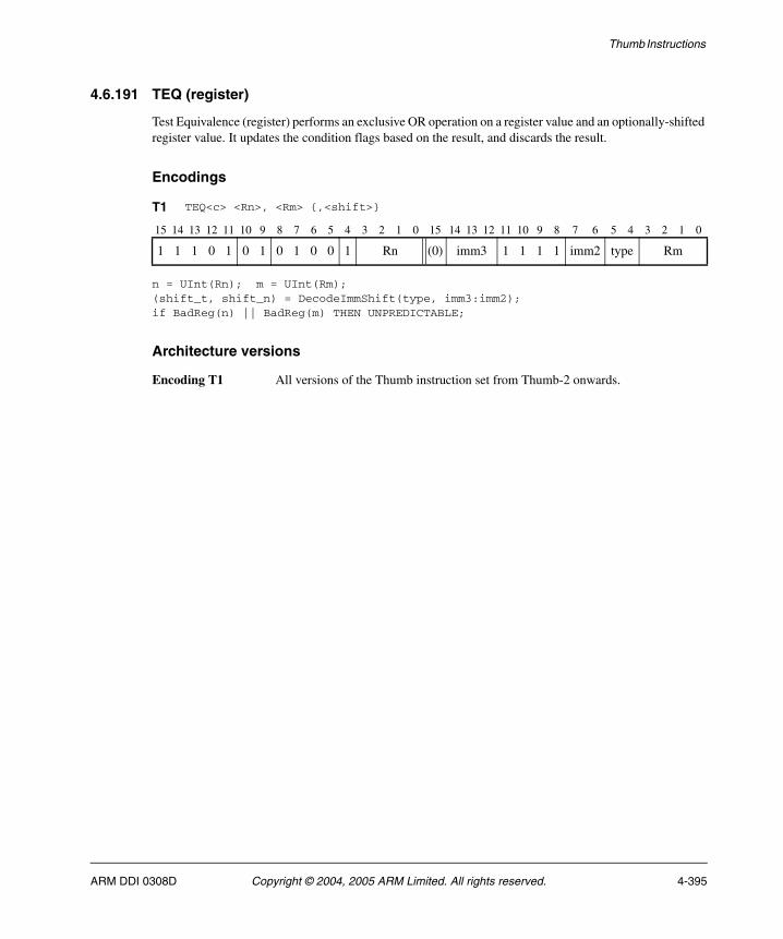
Thumb Instructions
4.6.191 TEQ (register)
Test Equivalence (register) performs an exclusive OR operation on a register value and an optionally-shifted register value. It updates the condition flags based on the result, and discards the result.
Encodings
n = UInt(Rn); m = UInt(Rm);(shift_t, shift_n) = DecodeImmShift(type, imm3:imm2);if BadReg(n) || BadReg(m) THEN UNPREDICTABLE;
Architecture versions
Encoding T1 All versions of the Thumb instruction set from Thumb-2 onwards.
T1 TEQ<c> <Rn>, <Rm> {,<shift>}
15 14 13 12 11 10 9 8 7 6 5 4 3 2 1 0 15 14 13 12 11 10 9 8 7 6 5 4 3 2 1 0
1 1 1 0 1 0 1 0 1 0 0 1 Rn (0) imm3 1 1 1 1 imm2 type Rm
ARM DDI 0308D Copyright © 2004, 2005 ARM Limited. All rights reserved. 4-395
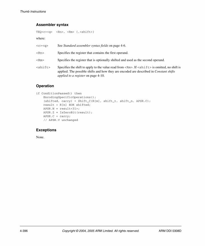
Thumb Instructions
Assembler syntax
TEQ<c><q> <Rn>, <Rm> {,<shift>}
where:
<c><q> See Standard assembler syntax fields on page 4-6.
<Rn> Specifies the register that contains the first operand.
<Rm> Specifies the register that is optionally shifted and used as the second operand.
<shift> Specifies the shift to apply to the value read from <Rm>. If <shift> is omitted, no shift is applied. The possible shifts and how they are encoded are described in Constant shifts applied to a register on page 4-10.
Operation
if ConditionPassed() then EncodingSpecificOperations(); (shifted, carry) = Shift_C(R[m], shift_t, shift_n, APSR.C); result = R[n] EOR shifted; APSR.N = result<31>; APSR.Z = IsZeroBit(result); APSR.C = carry; // APSR.V unchanged
Exceptions
None.
4-396 Copyright © 2004, 2005 ARM Limited. All rights reserved. ARM DDI 0308D
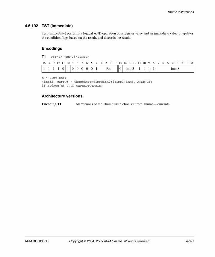
Thumb Instructions
4.6.192 TST (immediate)
Test (immediate) performs a logical AND operation on a register value and an immediate value. It updates the condition flags based on the result, and discards the result.
Encodings
n = UInt(Rn);(imm32, carry) = ThumbExpandImmWithC(i:imm3:imm8, APSR.C);if BadReg(n) then UNPREDICTABLE;
Architecture versions
Encoding T1 All versions of the Thumb instruction set from Thumb-2 onwards.
T1 TST<c> <Rn>,#<const>
15 14 13 12 11 10 9 8 7 6 5 4 3 2 1 0 15 14 13 12 11 10 9 8 7 6 5 4 3 2 1 0
1 1 1 1 0 i 0 0 0 0 0 1 Rn 0 imm3 1 1 1 1 imm8
ARM DDI 0308D Copyright © 2004, 2005 ARM Limited. All rights reserved. 4-397
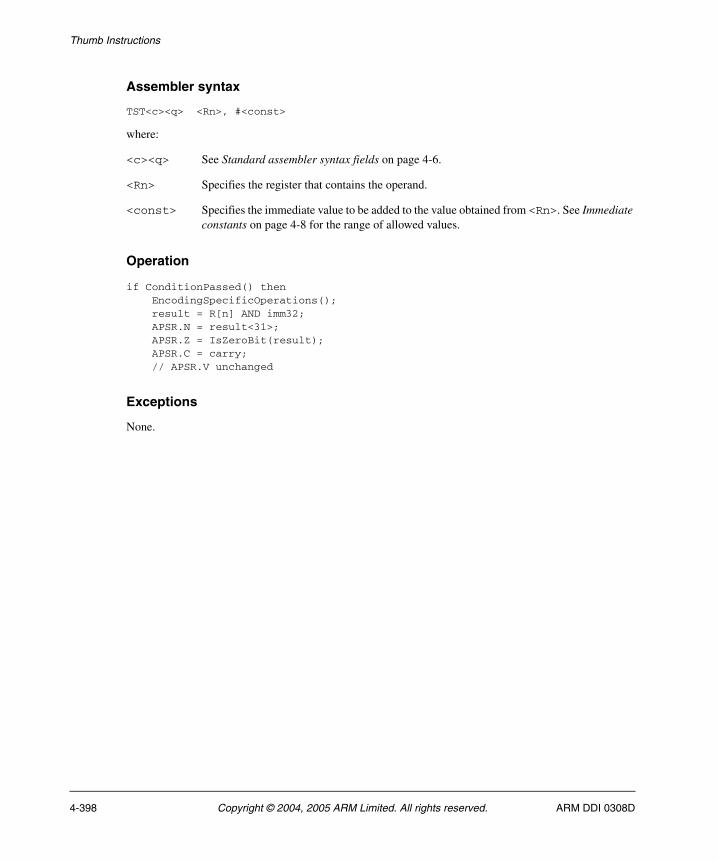
Thumb Instructions
Assembler syntax
TST<c><q> <Rn>, #<const>
where:
<c><q> See Standard assembler syntax fields on page 4-6.
<Rn> Specifies the register that contains the operand.
<const> Specifies the immediate value to be added to the value obtained from <Rn>. See Immediate constants on page 4-8 for the range of allowed values.
Operation
if ConditionPassed() then EncodingSpecificOperations(); result = R[n] AND imm32; APSR.N = result<31>; APSR.Z = IsZeroBit(result); APSR.C = carry; // APSR.V unchanged
Exceptions
None.
4-398 Copyright © 2004, 2005 ARM Limited. All rights reserved. ARM DDI 0308D
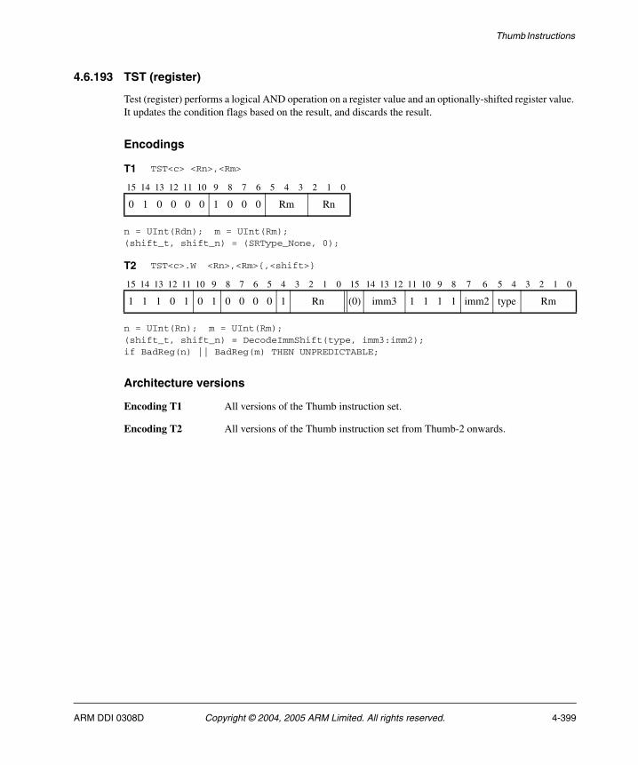
Thumb Instructions
4.6.193 TST (register)
Test (register) performs a logical AND operation on a register value and an optionally-shifted register value. It updates the condition flags based on the result, and discards the result.
Encodings
n = UInt(Rdn); m = UInt(Rm);(shift_t, shift_n) = (SRType_None, 0);
n = UInt(Rn); m = UInt(Rm);(shift_t, shift_n) = DecodeImmShift(type, imm3:imm2);if BadReg(n) || BadReg(m) THEN UNPREDICTABLE;
Architecture versions
Encoding T1 All versions of the Thumb instruction set.
Encoding T2 All versions of the Thumb instruction set from Thumb-2 onwards.
T1 TST<c> <Rn>,<Rm>
15 14 13 12 11 10 9 8 7 6 5 4 3 2 1 0
0 1 0 0 0 0 1 0 0 0 Rm Rn
T2 TST<c>.W <Rn>,<Rm>{,<shift>}
15 14 13 12 11 10 9 8 7 6 5 4 3 2 1 0 15 14 13 12 11 10 9 8 7 6 5 4 3 2 1 0
1 1 1 0 1 0 1 0 0 0 0 1 Rn (0) imm3 1 1 1 1 imm2 type Rm
ARM DDI 0308D Copyright © 2004, 2005 ARM Limited. All rights reserved. 4-399
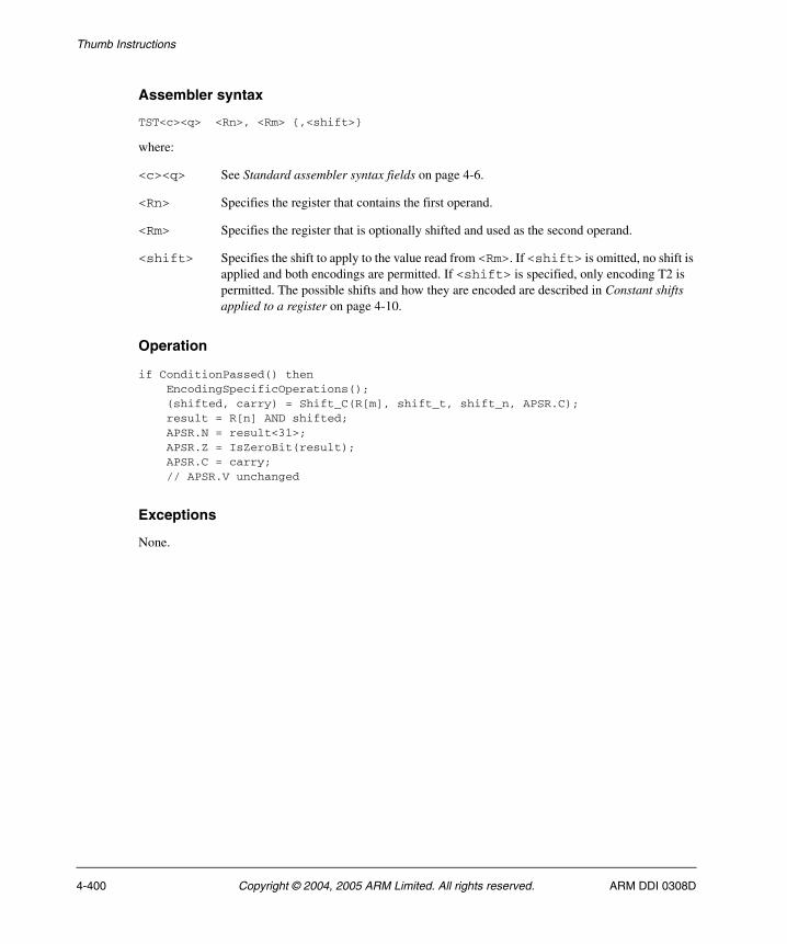
Thumb Instructions
Assembler syntax
TST<c><q> <Rn>, <Rm> {,<shift>}
where:
<c><q> See Standard assembler syntax fields on page 4-6.
<Rn> Specifies the register that contains the first operand.
<Rm> Specifies the register that is optionally shifted and used as the second operand.
<shift> Specifies the shift to apply to the value read from <Rm>. If <shift> is omitted, no shift is applied and both encodings are permitted. If <shift> is specified, only encoding T2 is permitted. The possible shifts and how they are encoded are described in Constant shifts applied to a register on page 4-10.
Operation
if ConditionPassed() then EncodingSpecificOperations(); (shifted, carry) = Shift_C(R[m], shift_t, shift_n, APSR.C); result = R[n] AND shifted; APSR.N = result<31>; APSR.Z = IsZeroBit(result); APSR.C = carry; // APSR.V unchanged
Exceptions
None.
4-400 Copyright © 2004, 2005 ARM Limited. All rights reserved. ARM DDI 0308D

Thumb Instructions
4.6.194 UADD16
Unsigned Add 16 performs two 16-bit unsigned integer additions, and writes the results to the destination register. It sets the GE bits in the APSR according to the results of the additions.
Encodings
d = UInt(Rd); n = UInt(Rn); m = UInt(Rm);if BadReg(d) || BadReg(n) || BadReg(m) then UNPREDICTABLE;
Architecture versions
Encoding T1 All versions of the Thumb instruction set from Thumb-2 onwards.
T1 UADD16<c> <Rd>,<Rn>,<Rm>
15 14 13 12 11 10 9 8 7 6 5 4 3 2 1 0 15 14 13 12 11 10 9 8 7 6 5 4 3 2 1 0
1 1 1 1 1 0 1 0 1 0 0 1 Rn 1 1 1 1 Rd 0 1 0 0 Rm
ARM DDI 0308D Copyright © 2004, 2005 ARM Limited. All rights reserved. 4-401
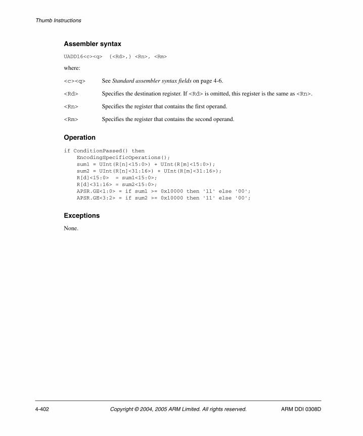
Thumb Instructions
Assembler syntax
UADD16<c><q> {<Rd>,} <Rn>, <Rm>
where:
<c><q> See Standard assembler syntax fields on page 4-6.
<Rd> Specifies the destination register. If <Rd> is omitted, this register is the same as <Rn>.
<Rn> Specifies the register that contains the first operand.
<Rm> Specifies the register that contains the second operand.
Operation
if ConditionPassed() then EncodingSpecificOperations(); sum1 = UInt(R[n]<15:0>) + UInt(R[m]<15:0>); sum2 = UInt(R[n]<31:16>) + UInt(R[m]<31:16>); R[d]<15:0> = sum1<15:0>; R[d]<31:16> = sum2<15:0>; APSR.GE<1:0> = if sum1 >= 0x10000 then '11' else '00'; APSR.GE<3:2> = if sum2 >= 0x10000 then '11' else '00';
Exceptions
None.
4-402 Copyright © 2004, 2005 ARM Limited. All rights reserved. ARM DDI 0308D

Thumb Instructions
4.6.195 UADD8
Unsigned Add 8 performs four unsigned 8-bit integer additions, and writes the results to the destination register. It sets the GE bits in the APSR according to the results of the additions.
Encodings
d = UInt(Rd); n = UInt(Rn); m = UInt(Rm);if BadReg(d) || BadReg(n) || BadReg(m) then UNPREDICTABLE;
Architecture versions
Encoding T1 All versions of the Thumb instruction set from Thumb-2 onwards.
T1 UADD8<c> <Rd>,<Rn>,<Rm>
15 14 13 12 11 10 9 8 7 6 5 4 3 2 1 0 15 14 13 12 11 10 9 8 7 6 5 4 3 2 1 0
1 1 1 1 1 0 1 0 1 0 0 0 Rn 1 1 1 1 Rd 0 1 0 0 Rm
ARM DDI 0308D Copyright © 2004, 2005 ARM Limited. All rights reserved. 4-403
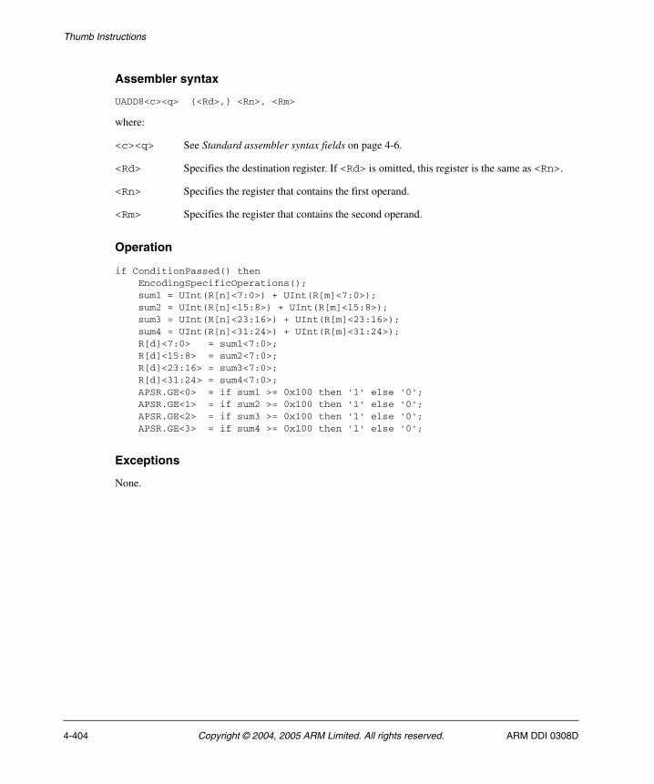
Thumb Instructions
Assembler syntax
UADD8<c><q> {<Rd>,} <Rn>, <Rm>
where:
<c><q> See Standard assembler syntax fields on page 4-6.
<Rd> Specifies the destination register. If <Rd> is omitted, this register is the same as <Rn>.
<Rn> Specifies the register that contains the first operand.
<Rm> Specifies the register that contains the second operand.
Operation
if ConditionPassed() then EncodingSpecificOperations(); sum1 = UInt(R[n]<7:0>) + UInt(R[m]<7:0>); sum2 = UInt(R[n]<15:8>) + UInt(R[m]<15:8>); sum3 = UInt(R[n]<23:16>) + UInt(R[m]<23:16>); sum4 = UInt(R[n]<31:24>) + UInt(R[m]<31:24>); R[d]<7:0> = sum1<7:0>; R[d]<15:8> = sum2<7:0>; R[d]<23:16> = sum3<7:0>; R[d]<31:24> = sum4<7:0>; APSR.GE<0> = if sum1 >= 0x100 then '1' else '0'; APSR.GE<1> = if sum2 >= 0x100 then '1' else '0'; APSR.GE<2> = if sum3 >= 0x100 then '1' else '0'; APSR.GE<3> = if sum4 >= 0x100 then '1' else '0';
Exceptions
None.
4-404 Copyright © 2004, 2005 ARM Limited. All rights reserved. ARM DDI 0308D
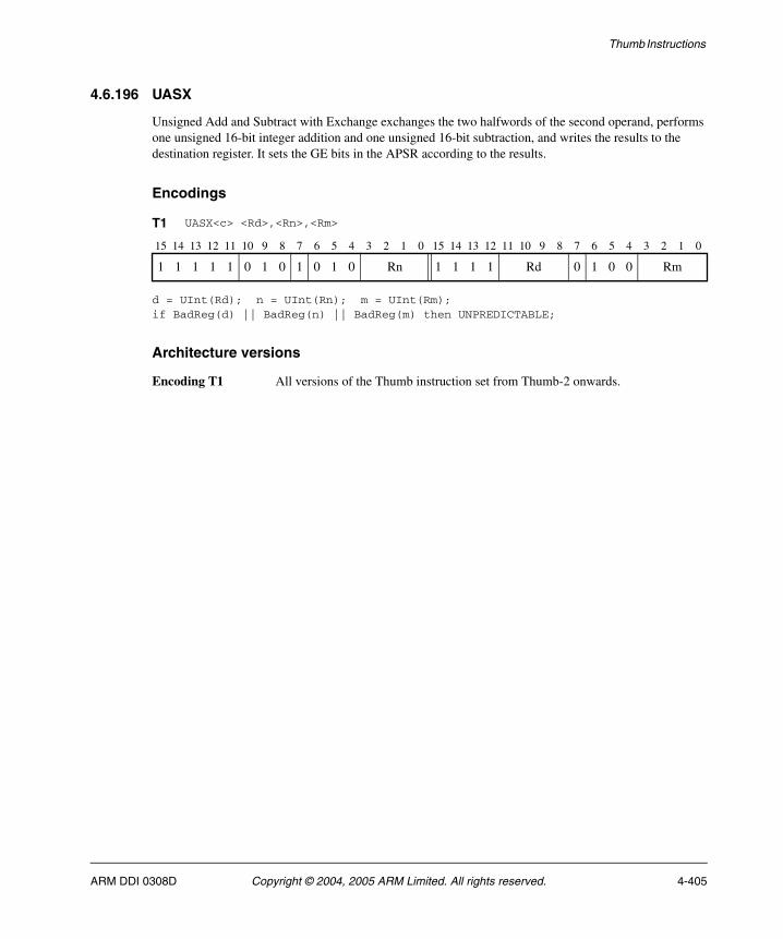
Thumb Instructions
4.6.196 UASX
Unsigned Add and Subtract with Exchange exchanges the two halfwords of the second operand, performs one unsigned 16-bit integer addition and one unsigned 16-bit subtraction, and writes the results to the destination register. It sets the GE bits in the APSR according to the results.
Encodings
d = UInt(Rd); n = UInt(Rn); m = UInt(Rm);if BadReg(d) || BadReg(n) || BadReg(m) then UNPREDICTABLE;
Architecture versions
Encoding T1 All versions of the Thumb instruction set from Thumb-2 onwards.
T1 UASX<c> <Rd>,<Rn>,<Rm>
15 14 13 12 11 10 9 8 7 6 5 4 3 2 1 0 15 14 13 12 11 10 9 8 7 6 5 4 3 2 1 0
1 1 1 1 1 0 1 0 1 0 1 0 Rn 1 1 1 1 Rd 0 1 0 0 Rm
ARM DDI 0308D Copyright © 2004, 2005 ARM Limited. All rights reserved. 4-405

Thumb Instructions
Assembler syntax
UASX<c><q> {<Rd>,} <Rn>, <Rm>
where:
<c><q> See Standard assembler syntax fields on page 4-6.
<Rd> Specifies the destination register. If <Rd> is omitted, this register is the same as <Rn>.
<Rn> Specifies the register that contains the first operand.
<Rm> Specifies the register that contains the second operand.
Operation
if ConditionPassed() then EncodingSpecificOperations(); diff = UInt(R[n]<15:0>) - UInt(R[m]<31:16>); sum = UInt(R[n]<31:16>) + UInt(R[m]<15:0>); R[d]<15:0> = diff<15:0>; R[d]<31:16> = sum<15:0>; APSR.GE<1:0> = if diff >= 0 then '11' else '00'; APSR.GE<3:2> = if sum >= 0x10000 then '11' else '00';
Exceptions
None.
4-406 Copyright © 2004, 2005 ARM Limited. All rights reserved. ARM DDI 0308D
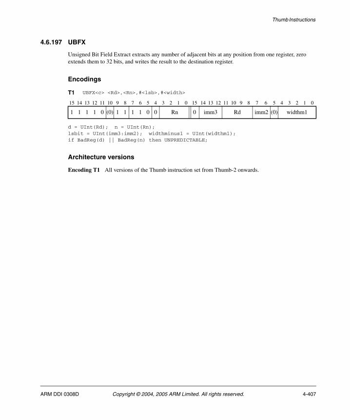
Thumb Instructions
4.6.197 UBFX
Unsigned Bit Field Extract extracts any number of adjacent bits at any position from one register, zero extends them to 32 bits, and writes the result to the destination register.
Encodings
d = UInt(Rd); n = UInt(Rn);lsbit = UInt(imm3:imm2); widthminus1 = UInt(widthm1);if BadReg(d) || BadReg(n) then UNPREDICTABLE;
Architecture versions
Encoding T1 All versions of the Thumb instruction set from Thumb-2 onwards.
T1 UBFX<c> <Rd>,<Rn>,#<lsb>,#<width>
15 14 13 12 11 10 9 8 7 6 5 4 3 2 1 0 15 14 13 12 11 10 9 8 7 6 5 4 3 2 1 0
1 1 1 1 0 (0) 1 1 1 1 0 0 Rn 0 imm3 Rd imm2 (0) widthm1
ARM DDI 0308D Copyright © 2004, 2005 ARM Limited. All rights reserved. 4-407
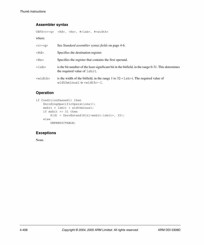
Thumb Instructions
Assembler syntax
UBFX<c><q> <Rd>, <Rn>, #<lsb>, #<width>
where:
<c><q> See Standard assembler syntax fields on page 4-6.
<Rd> Specifies the destination register.
<Rn> Specifies the register that contains the first operand.
<lsb> is the bit number of the least significant bit in the bitfield, in the range 0-31. This determines the required value of lsbit.
<width> is the width of the bitfield, in the range 1 to 32-<lsb>). The required value of widthminus1 is <width>-1.
Operation
if ConditionPassed() then EncodingSpecificOperations(); msbit = lsbit + widthminus1; if msbit <= 31 then R[d] = ZeroExtend(R[n]<msbit:lsbit>, 32); else UNPREDICTABLE;
Exceptions
None.
4-408 Copyright © 2004, 2005 ARM Limited. All rights reserved. ARM DDI 0308D
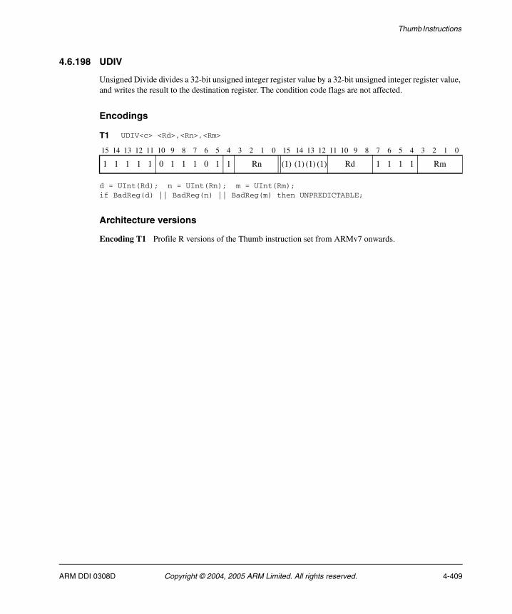
Thumb Instructions
4.6.198 UDIV
Unsigned Divide divides a 32-bit unsigned integer register value by a 32-bit unsigned integer register value, and writes the result to the destination register. The condition code flags are not affected.
Encodings
d = UInt(Rd); n = UInt(Rn); m = UInt(Rm);if BadReg(d) || BadReg(n) || BadReg(m) then UNPREDICTABLE;
Architecture versions
Encoding T1 Profile R versions of the Thumb instruction set from ARMv7 onwards.
T1 UDIV<c> <Rd>,<Rn>,<Rm>
15 14 13 12 11 10 9 8 7 6 5 4 3 2 1 0 15 14 13 12 11 10 9 8 7 6 5 4 3 2 1 0
1 1 1 1 1 0 1 1 1 0 1 1 Rn (1) (1) (1) (1) Rd 1 1 1 1 Rm
ARM DDI 0308D Copyright © 2004, 2005 ARM Limited. All rights reserved. 4-409
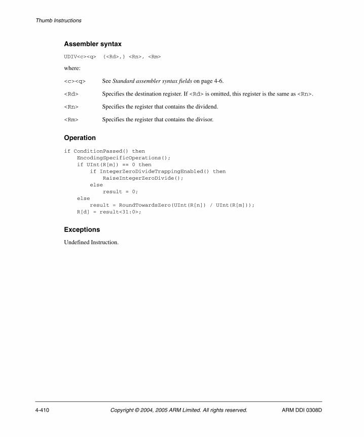
Thumb Instructions
Assembler syntax
UDIV<c><q> {<Rd>,} <Rn>, <Rm>
where:
<c><q> See Standard assembler syntax fields on page 4-6.
<Rd> Specifies the destination register. If <Rd> is omitted, this register is the same as <Rn>.
<Rn> Specifies the register that contains the dividend.
<Rm> Specifies the register that contains the divisor.
Operation
if ConditionPassed() then EncodingSpecificOperations(); if UInt(R[m]) == 0 then if IntegerZeroDivideTrappingEnabled() then RaiseIntegerZeroDivide(); else result = 0; else result = RoundTowardsZero(UInt(R[n]) / UInt(R[m])); R[d] = result<31:0>;
Exceptions
Undefined Instruction.
4-410 Copyright © 2004, 2005 ARM Limited. All rights reserved. ARM DDI 0308D

Thumb Instructions
4.6.199 UHADD16
Unsigned Halving Add 16 performs two unsigned 16-bit integer additions, halves the results, and writes the results to the destination register. It does not affect any flags.
Encodings
d = UInt(Rd); n = UInt(Rn); m = UInt(Rm);if BadReg(d) || BadReg(n) || BadReg(m) then UNPREDICTABLE;
Architecture versions
Encoding T1 All versions of the Thumb instruction set from Thumb-2 onwards.
T1 UHADD16<c> <Rd>,<Rn>,<Rm>
15 14 13 12 11 10 9 8 7 6 5 4 3 2 1 0 15 14 13 12 11 10 9 8 7 6 5 4 3 2 1 0
1 1 1 1 1 0 1 0 1 0 0 1 Rn 1 1 1 1 Rd 0 1 1 0 Rm
ARM DDI 0308D Copyright © 2004, 2005 ARM Limited. All rights reserved. 4-411

Thumb Instructions
Assembler syntax
UHADD16<c><q> {<Rd>,} <Rn>, <Rm>
where:
<c><q> See Standard assembler syntax fields on page 4-6.
<Rd> Specifies the destination register. If <Rd> is omitted, this register is the same as <Rn>.
<Rn> Specifies the register that contains the first operand.
<Rm> Specifies the register that contains the second operand.
Operation
if ConditionPassed() then EncodingSpecificOperations(); sum1 = UInt(R[n]<15:0>) + UInt(R[m]<15:0>); sum2 = UInt(R[n]<31:16>) + UInt(R[m]<31:16>); R[d]<15:0> = sum1<16:1>; R[d]<31:16> = sum2<16:1>;
Exceptions
None.
4-412 Copyright © 2004, 2005 ARM Limited. All rights reserved. ARM DDI 0308D

Thumb Instructions
4.6.200 UHADD8
Unsigned Halving Add 8 performs four unsigned 8-bit integer additions, halves the results, and writes the results to the destination register. It does not affect any flags.
Encodings
d = UInt(Rd); n = UInt(Rn); m = UInt(Rm);if BadReg(d) || BadReg(n) || BadReg(m) then UNPREDICTABLE;
Architecture versions
Encoding T1 All versions of the Thumb instruction set from Thumb-2 onwards.
T1 UHADD8<c> <Rd>,<Rn>,<Rm>
15 14 13 12 11 10 9 8 7 6 5 4 3 2 1 0 15 14 13 12 11 10 9 8 7 6 5 4 3 2 1 0
1 1 1 1 1 0 1 0 1 0 0 0 Rn 1 1 1 1 Rd 0 1 1 0 Rm
ARM DDI 0308D Copyright © 2004, 2005 ARM Limited. All rights reserved. 4-413

Thumb Instructions
Assembler syntax
UHADD8<c><q> {<Rd>,} <Rn>, <Rm>
where:
<c><q> See Standard assembler syntax fields on page 4-6.
<Rd> Specifies the destination register. If <Rd> is omitted, this register is the same as <Rn>.
<Rn> Specifies the register that contains the first operand.
<Rm> Specifies the register that contains the second operand.
Operation
if ConditionPassed() then EncodingSpecificOperations(); sum1 = UInt(R[n]<7:0>) + UInt(R[m]<7:0>); sum2 = UInt(R[n]<15:8>) + UInt(R[m]<15:8>); sum3 = UInt(R[n]<23:16>) + UInt(R[m]<23:16>); sum4 = UInt(R[n]<31:24>) + UInt(R[m]<31:24>); R[d]<7:0> = sum1<8:1>; R[d]<15:8> = sum2<8:1>; R[d]<23:16> = sum3<8:1>; R[d]<31:24> = sum4<8:1>;
Exceptions
None.
4-414 Copyright © 2004, 2005 ARM Limited. All rights reserved. ARM DDI 0308D
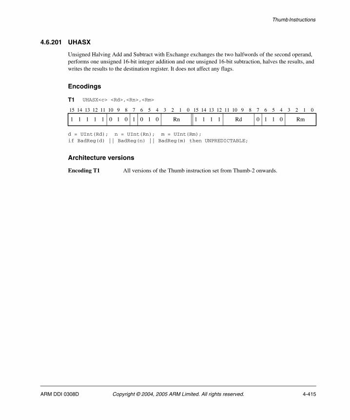
Thumb Instructions
4.6.201 UHASX
Unsigned Halving Add and Subtract with Exchange exchanges the two halfwords of the second operand, performs one unsigned 16-bit integer addition and one unsigned 16-bit subtraction, halves the results, and writes the results to the destination register. It does not affect any flags.
Encodings
d = UInt(Rd); n = UInt(Rn); m = UInt(Rm);if BadReg(d) || BadReg(n) || BadReg(m) then UNPREDICTABLE;
Architecture versions
Encoding T1 All versions of the Thumb instruction set from Thumb-2 onwards.
T1 UHASX<c> <Rd>,<Rn>,<Rm>
15 14 13 12 11 10 9 8 7 6 5 4 3 2 1 0 15 14 13 12 11 10 9 8 7 6 5 4 3 2 1 0
1 1 1 1 1 0 1 0 1 0 1 0 Rn 1 1 1 1 Rd 0 1 1 0 Rm
ARM DDI 0308D Copyright © 2004, 2005 ARM Limited. All rights reserved. 4-415

Thumb Instructions
Assembler syntax
UHASX<c><q> {<Rd>,} <Rn>, <Rm>
where:
<c><q> See Standard assembler syntax fields on page 4-6.
<Rd> Specifies the destination register. If <Rd> is omitted, this register is the same as <Rn>.
<Rn> Specifies the register that contains the first operand.
<Rm> Specifies the register that contains the second operand.
Operation
if ConditionPassed() then EncodingSpecificOperations(); diff = UInt(R[n]<15:0>) - UInt(R[m]<31:16>); sum = UInt(R[n]<31:16>) + UInt(R[m]<15:0>); R[d]<15:0> = diff<16:1>; R[d]<31:16> = sum<16:1>;
Exceptions
None.
4-416 Copyright © 2004, 2005 ARM Limited. All rights reserved. ARM DDI 0308D
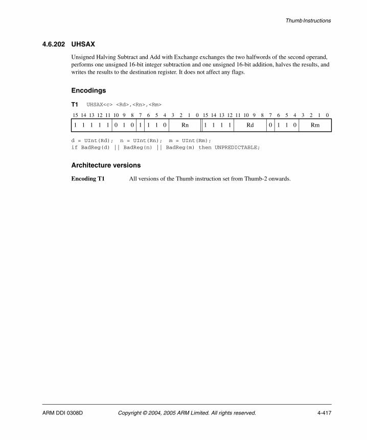
Thumb Instructions
4.6.202 UHSAX
Unsigned Halving Subtract and Add with Exchange exchanges the two halfwords of the second operand, performs one unsigned 16-bit integer subtraction and one unsigned 16-bit addition, halves the results, and writes the results to the destination register. It does not affect any flags.
Encodings
d = UInt(Rd); n = UInt(Rn); m = UInt(Rm);if BadReg(d) || BadReg(n) || BadReg(m) then UNPREDICTABLE;
Architecture versions
Encoding T1 All versions of the Thumb instruction set from Thumb-2 onwards.
T1 UHSAX<c> <Rd>,<Rn>,<Rm>
15 14 13 12 11 10 9 8 7 6 5 4 3 2 1 0 15 14 13 12 11 10 9 8 7 6 5 4 3 2 1 0
1 1 1 1 1 0 1 0 1 1 1 0 Rn 1 1 1 1 Rd 0 1 1 0 Rm
ARM DDI 0308D Copyright © 2004, 2005 ARM Limited. All rights reserved. 4-417

Thumb Instructions
Assembler syntax
UHSAX<c><q> {<Rd>,} <Rn>, <Rm>
where:
<c><q> See Standard assembler syntax fields on page 4-6.
<Rd> Specifies the destination register. If <Rd> is omitted, this register is the same as <Rn>.
<Rn> Specifies the register that contains the first operand.
<Rm> Specifies the register that contains the second operand.
Operation
if ConditionPassed() then EncodingSpecificOperations(); sum = UInt(R[n]<15:0>) + UInt(R[m]<31:16>); diff = UInt(R[n]<31:16>) - UInt(R[m]<15:0>); R[d]<15:0> = sum<16:1>; R[d]<31:16> = diff<16:1>;
Exceptions
None.
4-418 Copyright © 2004, 2005 ARM Limited. All rights reserved. ARM DDI 0308D

Thumb Instructions
4.6.203 UHSUB16
Unsigned Halving Subtract 16 performs two unsigned 16-bit integer subtractions, halves the results, and writes the results to the destination register. It does not affect any flags.
Encodings
d = UInt(Rd); n = UInt(Rn); m = UInt(Rm);if BadReg(d) || BadReg(n) || BadReg(m) then UNPREDICTABLE;
Architecture versions
Encoding T1 All versions of the Thumb instruction set from Thumb-2 onwards.
T1 UHSUB16<c> <Rd>,<Rn>,<Rm>
15 14 13 12 11 10 9 8 7 6 5 4 3 2 1 0 15 14 13 12 11 10 9 8 7 6 5 4 3 2 1 0
1 1 1 1 1 0 1 0 1 1 0 1 Rn 1 1 1 1 Rd 0 1 1 0 Rm
ARM DDI 0308D Copyright © 2004, 2005 ARM Limited. All rights reserved. 4-419
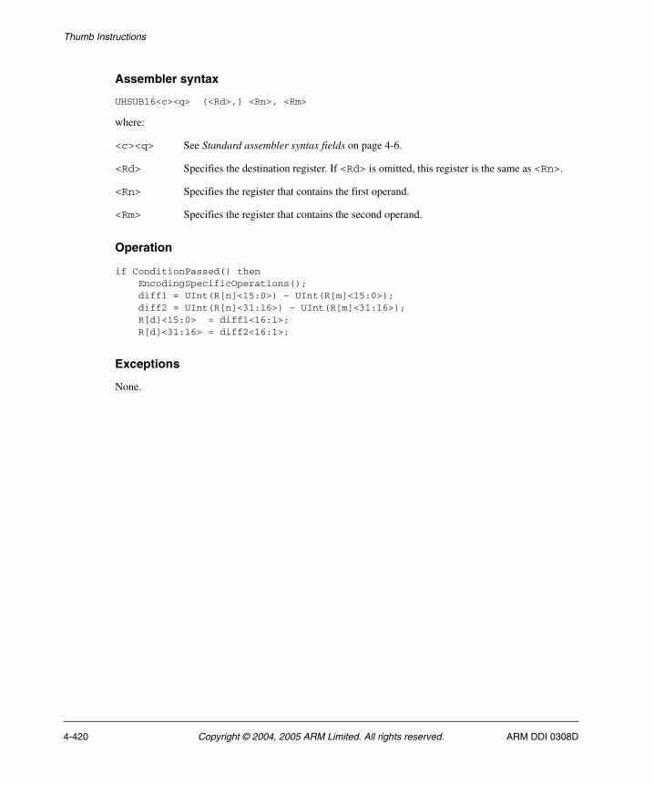
Thumb Instructions
Assembler syntax
UHSUB16<c><q> {<Rd>,} <Rn>, <Rm>
where:
<c><q> See Standard assembler syntax fields on page 4-6.
<Rd> Specifies the destination register. If <Rd> is omitted, this register is the same as <Rn>.
<Rn> Specifies the register that contains the first operand.
<Rm> Specifies the register that contains the second operand.
Operation
if ConditionPassed() then EncodingSpecificOperations(); diff1 = UInt(R[n]<15:0>) - UInt(R[m]<15:0>); diff2 = UInt(R[n]<31:16>) - UInt(R[m]<31:16>); R[d]<15:0> = diff1<16:1>; R[d]<31:16> = diff2<16:1>;
Exceptions
None.
4-420 Copyright © 2004, 2005 ARM Limited. All rights reserved. ARM DDI 0308D
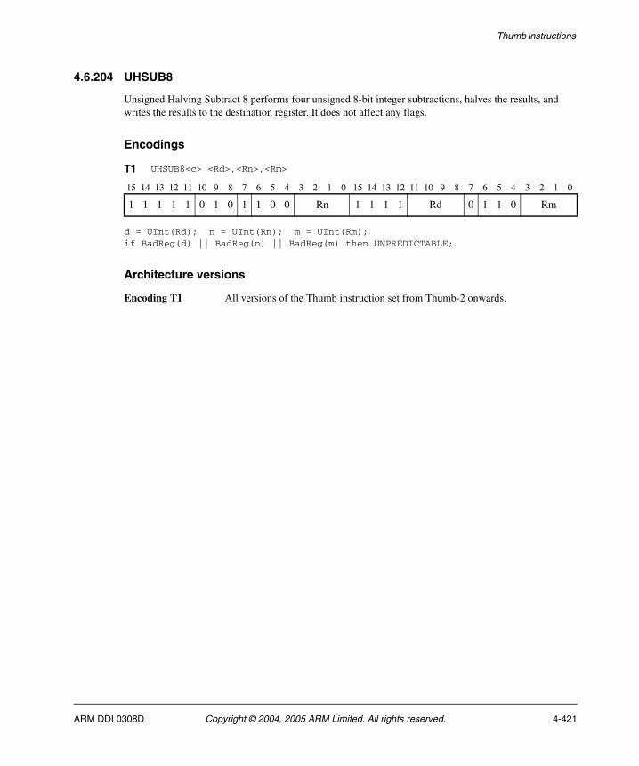
Thumb Instructions
4.6.204 UHSUB8
Unsigned Halving Subtract 8 performs four unsigned 8-bit integer subtractions, halves the results, and writes the results to the destination register. It does not affect any flags.
Encodings
d = UInt(Rd); n = UInt(Rn); m = UInt(Rm);if BadReg(d) || BadReg(n) || BadReg(m) then UNPREDICTABLE;
Architecture versions
Encoding T1 All versions of the Thumb instruction set from Thumb-2 onwards.
T1 UHSUB8<c> <Rd>,<Rn>,<Rm>
15 14 13 12 11 10 9 8 7 6 5 4 3 2 1 0 15 14 13 12 11 10 9 8 7 6 5 4 3 2 1 0
1 1 1 1 1 0 1 0 1 1 0 0 Rn 1 1 1 1 Rd 0 1 1 0 Rm
ARM DDI 0308D Copyright © 2004, 2005 ARM Limited. All rights reserved. 4-421

Thumb Instructions
Assembler syntax
UHSUB8<c><q> {<Rd>,} <Rn>, <Rm>
where:
<c><q> See Standard assembler syntax fields on page 4-6.
<Rd> Specifies the destination register. If <Rd> is omitted, this register is the same as <Rn>.
<Rn> Specifies the register that contains the first operand.
<Rm> Specifies the register that contains the second operand.
Operation
if ConditionPassed() then EncodingSpecificOperations(); diff1 = UInt(R[n]<7:0>) - UInt(R[m]<7:0>); diff2 = UInt(R[n]<15:8>) - UInt(R[m]<15:8>); diff3 = UInt(R[n]<23:16>) - UInt(R[m]<23:16>); diff4 = UInt(R[n]<31:24>) - UInt(R[m]<31:24>); R[d]<7:0> = diff1<8:1>; R[d]<15:8> = diff2<8:1>; R[d]<23:16> = diff3<8:1>; R[d]<31:24> = diff4<8:1>;
Exceptions
None.
4-422 Copyright © 2004, 2005 ARM Limited. All rights reserved. ARM DDI 0308D
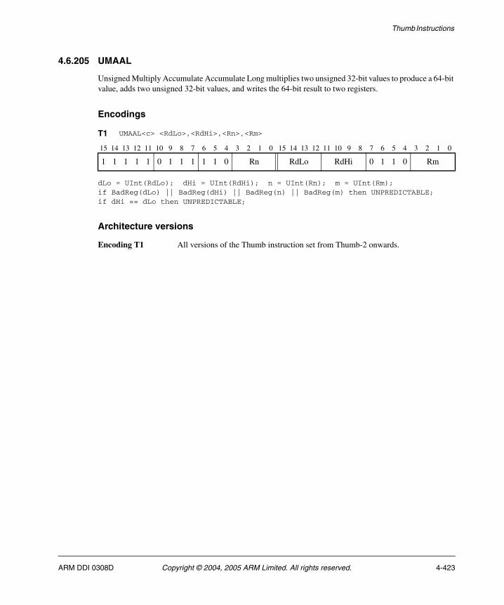
Thumb Instructions
4.6.205 UMAAL
Unsigned Multiply Accumulate Accumulate Long multiplies two unsigned 32-bit values to produce a 64-bit value, adds two unsigned 32-bit values, and writes the 64-bit result to two registers.
Encodings
dLo = UInt(RdLo); dHi = UInt(RdHi); n = UInt(Rn); m = UInt(Rm);if BadReg(dLo) || BadReg(dHi) || BadReg(n) || BadReg(m) then UNPREDICTABLE;if dHi == dLo then UNPREDICTABLE;
Architecture versions
Encoding T1 All versions of the Thumb instruction set from Thumb-2 onwards.
T1 UMAAL<c> <RdLo>,<RdHi>,<Rn>,<Rm>
15 14 13 12 11 10 9 8 7 6 5 4 3 2 1 0 15 14 13 12 11 10 9 8 7 6 5 4 3 2 1 0
1 1 1 1 1 0 1 1 1 1 1 0 Rn RdLo RdHi 0 1 1 0 Rm
ARM DDI 0308D Copyright © 2004, 2005 ARM Limited. All rights reserved. 4-423
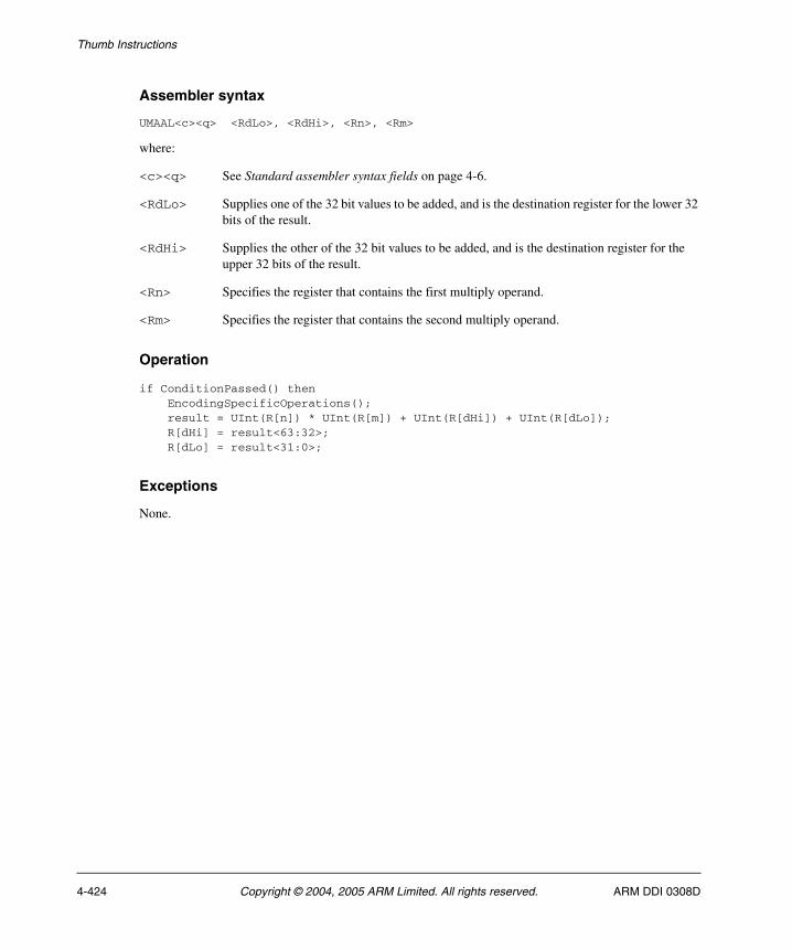
Thumb Instructions
Assembler syntax
UMAAL<c><q> <RdLo>, <RdHi>, <Rn>, <Rm>
where:
<c><q> See Standard assembler syntax fields on page 4-6.
<RdLo> Supplies one of the 32 bit values to be added, and is the destination register for the lower 32 bits of the result.
<RdHi> Supplies the other of the 32 bit values to be added, and is the destination register for the upper 32 bits of the result.
<Rn> Specifies the register that contains the first multiply operand.
<Rm> Specifies the register that contains the second multiply operand.
Operation
if ConditionPassed() then EncodingSpecificOperations(); result = UInt(R[n]) * UInt(R[m]) + UInt(R[dHi]) + UInt(R[dLo]); R[dHi] = result<63:32>; R[dLo] = result<31:0>;
Exceptions
None.
4-424 Copyright © 2004, 2005 ARM Limited. All rights reserved. ARM DDI 0308D
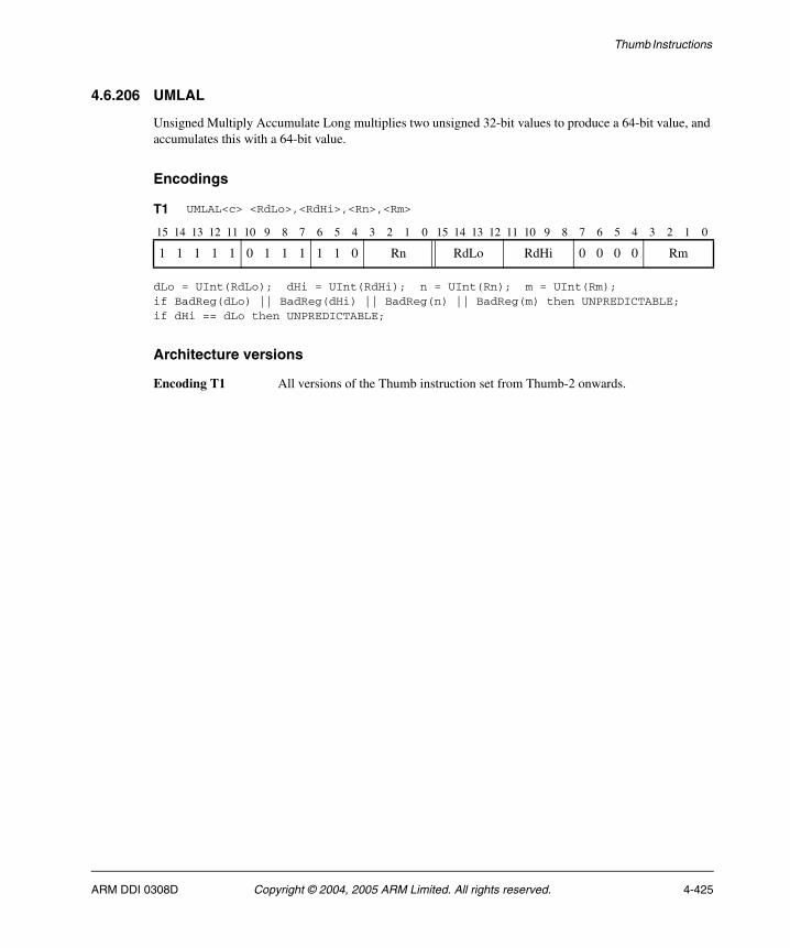
Thumb Instructions
4.6.206 UMLAL
Unsigned Multiply Accumulate Long multiplies two unsigned 32-bit values to produce a 64-bit value, and accumulates this with a 64-bit value.
Encodings
dLo = UInt(RdLo); dHi = UInt(RdHi); n = UInt(Rn); m = UInt(Rm);if BadReg(dLo) || BadReg(dHi) || BadReg(n) || BadReg(m) then UNPREDICTABLE;if dHi == dLo then UNPREDICTABLE;
Architecture versions
Encoding T1 All versions of the Thumb instruction set from Thumb-2 onwards.
T1 UMLAL<c> <RdLo>,<RdHi>,<Rn>,<Rm>
15 14 13 12 11 10 9 8 7 6 5 4 3 2 1 0 15 14 13 12 11 10 9 8 7 6 5 4 3 2 1 0
1 1 1 1 1 0 1 1 1 1 1 0 Rn RdLo RdHi 0 0 0 0 Rm
ARM DDI 0308D Copyright © 2004, 2005 ARM Limited. All rights reserved. 4-425
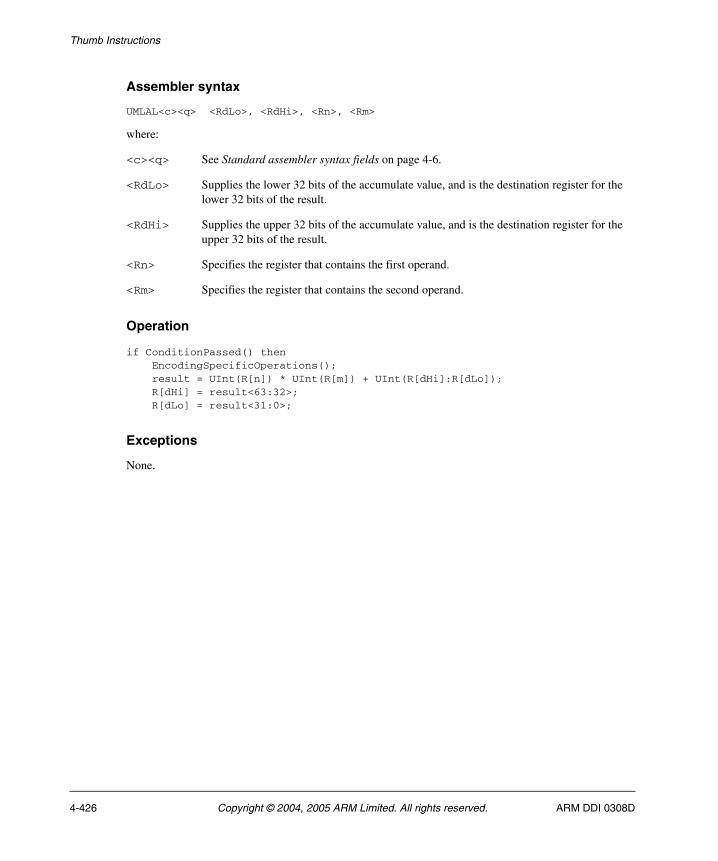
Thumb Instructions
Assembler syntax
UMLAL<c><q> <RdLo>, <RdHi>, <Rn>, <Rm>
where:
<c><q> See Standard assembler syntax fields on page 4-6.
<RdLo> Supplies the lower 32 bits of the accumulate value, and is the destination register for the lower 32 bits of the result.
<RdHi> Supplies the upper 32 bits of the accumulate value, and is the destination register for the upper 32 bits of the result.
<Rn> Specifies the register that contains the first operand.
<Rm> Specifies the register that contains the second operand.
Operation
if ConditionPassed() then EncodingSpecificOperations(); result = UInt(R[n]) * UInt(R[m]) + UInt(R[dHi]:R[dLo]); R[dHi] = result<63:32>; R[dLo] = result<31:0>;
Exceptions
None.
4-426 Copyright © 2004, 2005 ARM Limited. All rights reserved. ARM DDI 0308D

Thumb Instructions
4.6.207 UMULL
Unsigned Multiply Long multiplies two 32-bit unsigned values to produce a 64-bit result.
Encodings
dLo = UInt(RdLo); dHi = UInt(RdHi); n = UInt(Rn); m = UInt(Rm);if BadReg(dLo) || BadReg(dHi) || BadReg(n) || BadReg(m) then UNPREDICTABLE;if dHi == dLo then UNPREDICTABLE;
Architecture versions
Encoding T1 All versions of the Thumb instruction set from Thumb-2 onwards.
T1 UMULL<c> <RdLo>,<RdHi>,<Rn>,<Rm>
15 14 13 12 11 10 9 8 7 6 5 4 3 2 1 0 15 14 13 12 11 10 9 8 7 6 5 4 3 2 1 0
1 1 1 1 1 0 1 1 1 0 1 0 Rn RdLo RdHi 0 0 0 0 Rm
ARM DDI 0308D Copyright © 2004, 2005 ARM Limited. All rights reserved. 4-427
Thumb Instructions
Assembler syntax
UMULL<c><q> <RdLo>, <RdHi>, <Rn>, <Rm>
where:
<c><q> See Standard assembler syntax fields on page 4-6.
<RdLo> Stores the lower 32 bits of the result.
<RdHi> Stores the upper 32 bits of the result.
<Rn> Specifies the register that contains the first operand.
<Rm> Specifies the register that contains the second operand.
Operation
if ConditionPassed() then EncodingSpecificOperations(); result = UInt(R[n])*Uint(R[m]); R[dHi] = result<63:32>; R[dLo] = result<31:0>;
Exceptions
None.
4-428 Copyright © 2004, 2005 ARM Limited. All rights reserved. ARM DDI 0308D

Thumb Instructions
4.6.208 UQADD16
Unsigned Saturating Add 16 performs two unsigned 16-bit integer additions, saturates the results to the 16-bit unsigned integer range 0 ≤ x ≤ 216 – 1, and writes the results to the destination register. It does not affect any flags.
Encodings
d = UInt(Rd); n = UInt(Rn); m = UInt(Rm);if BadReg(d) || BadReg(n) || BadReg(m) then UNPREDICTABLE;
Architecture versions
Encoding T1 All versions of the Thumb instruction set from Thumb-2 onwards.
T1 UQADD16<c> <Rd>,<Rn>,<Rm>
15 14 13 12 11 10 9 8 7 6 5 4 3 2 1 0 15 14 13 12 11 10 9 8 7 6 5 4 3 2 1 0
1 1 1 1 1 0 1 0 1 0 0 1 Rn 1 1 1 1 Rd 0 1 0 1 Rm
ARM DDI 0308D Copyright © 2004, 2005 ARM Limited. All rights reserved. 4-429
Thumb Instructions
Assembler syntax
UQADD16<c><q> {<Rd>,} <Rn>, <Rm>
where:
<c><q> See Standard assembler syntax fields on page 4-6.
<Rd> Specifies the destination register. If <Rd> is omitted, this register is the same as <Rn>.
<Rn> Specifies the register that contains the first operand.
<Rm> Specifies the register that contains the second operand.
Operation
if ConditionPassed() then EncodingSpecificOperations(); sum1 = UInt(R[n]<15:0>) + UInt(R[m]<15:0>); sum2 = UInt(R[n]<31:16>) + UInt(R[m]<31:16>); R[d]<15:0> = UnsignedSat(sum1, 16); R[d]<31:16> = UnsignedSat(sum2, 16);
Exceptions
None.
4-430 Copyright © 2004, 2005 ARM Limited. All rights reserved. ARM DDI 0308D
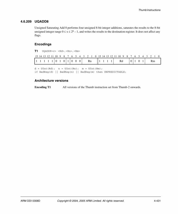
Thumb Instructions
4.6.209 UQADD8
Unsigned Saturating Add 8 performs four unsigned 8-bit integer additions, saturates the results to the 8-bit unsigned integer range 0 ≤ x ≤ 28 – 1, and writes the results to the destination register. It does not affect any flags.
Encodings
d = UInt(Rd); n = UInt(Rn); m = UInt(Rm);if BadReg(d) || BadReg(n) || BadReg(m) then UNPREDICTABLE;
Architecture versions
Encoding T1 All versions of the Thumb instruction set from Thumb-2 onwards.
T1 UQADD8<c> <Rd>,<Rn>,<Rm>
15 14 13 12 11 10 9 8 7 6 5 4 3 2 1 0 15 14 13 12 11 10 9 8 7 6 5 4 3 2 1 0
1 1 1 1 1 0 1 0 1 0 0 0 Rn 1 1 1 1 Rd 0 1 0 1 Rm
ARM DDI 0308D Copyright © 2004, 2005 ARM Limited. All rights reserved. 4-431

Thumb Instructions
Assembler syntax
UQADD8<c><q> {<Rd>,} <Rn>, <Rm>
where:
<c><q> See Standard assembler syntax fields on page 4-6.
<Rd> Specifies the destination register. If <Rd> is omitted, this register is the same as <Rn>.
<Rn> Specifies the register that contains the first operand.
<Rm> Specifies the register that contains the second operand.
Operation
if ConditionPassed() then EncodingSpecificOperations(); sum1 = UInt(R[n]<7:0>) + UInt(R[m]<7:0>); sum2 = UInt(R[n]<15:8>) + UInt(R[m]<15:8>); sum3 = UInt(R[n]<23:16>) + UInt(R[m]<23:16>); sum4 = UInt(R[n]<31:24>) + UInt(R[m]<31:24>); R[d]<7:0> = UnsignedSat(sum1, 8); R[d]<15:8> = UnsignedSat(sum2, 8); R[d]<23:16> = UnsignedSat(sum3, 8); R[d]<31:24> = UnsignedSat(sum4, 8);
Exceptions
None.
4-432 Copyright © 2004, 2005 ARM Limited. All rights reserved. ARM DDI 0308D
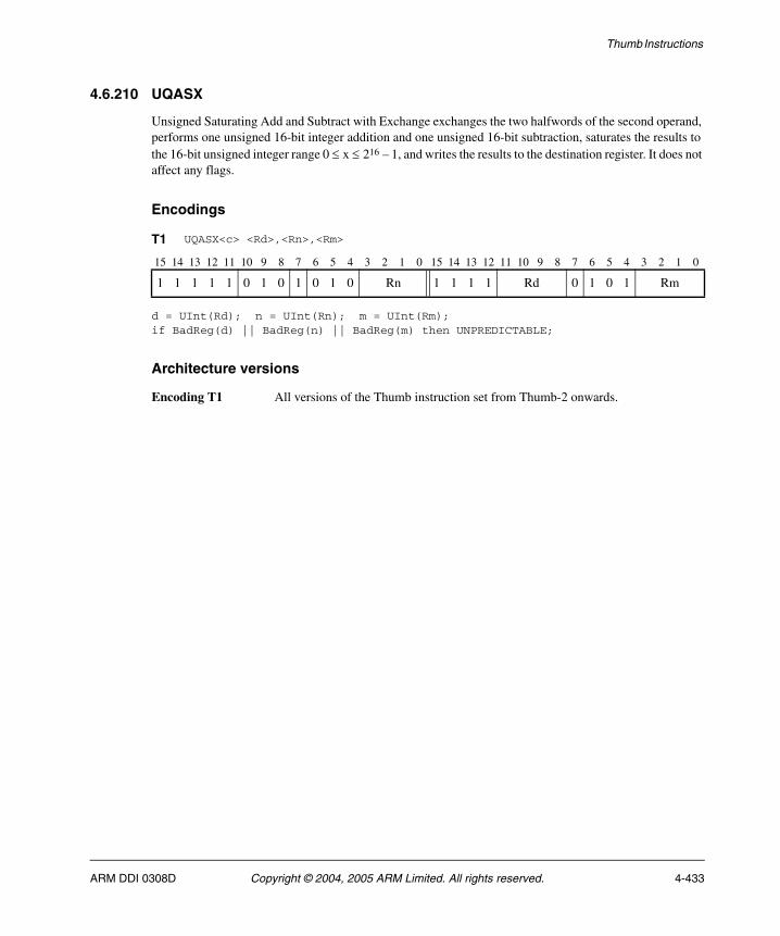
Thumb Instructions
4.6.210 UQASX
Unsigned Saturating Add and Subtract with Exchange exchanges the two halfwords of the second operand, performs one unsigned 16-bit integer addition and one unsigned 16-bit subtraction, saturates the results to the 16-bit unsigned integer range 0 ≤ x ≤ 216 – 1, and writes the results to the destination register. It does not affect any flags.
Encodings
d = UInt(Rd); n = UInt(Rn); m = UInt(Rm);if BadReg(d) || BadReg(n) || BadReg(m) then UNPREDICTABLE;
Architecture versions
Encoding T1 All versions of the Thumb instruction set from Thumb-2 onwards.
T1 UQASX<c> <Rd>,<Rn>,<Rm>
15 14 13 12 11 10 9 8 7 6 5 4 3 2 1 0 15 14 13 12 11 10 9 8 7 6 5 4 3 2 1 0
1 1 1 1 1 0 1 0 1 0 1 0 Rn 1 1 1 1 Rd 0 1 0 1 Rm
ARM DDI 0308D Copyright © 2004, 2005 ARM Limited. All rights reserved. 4-433
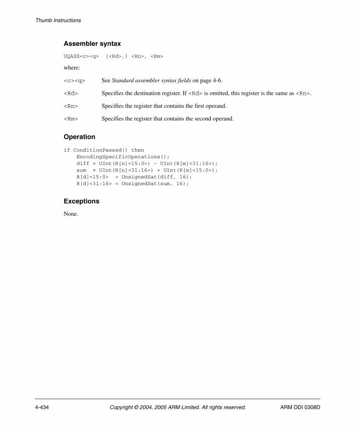
Thumb Instructions
Assembler syntax
UQASX<c><q> {<Rd>,} <Rn>, <Rm>
where:
<c><q> See Standard assembler syntax fields on page 4-6.
<Rd> Specifies the destination register. If <Rd> is omitted, this register is the same as <Rn>.
<Rn> Specifies the register that contains the first operand.
<Rm> Specifies the register that contains the second operand.
Operation
if ConditionPassed() then EncodingSpecificOperations(); diff = UInt(R[n]<15:0>) - UInt(R[m]<31:16>); sum = UInt(R[n]<31:16>) + UInt(R[m]<15:0>); R[d]<15:0> = UnsignedSat(diff, 16); R[d]<31:16> = UnsignedSat(sum, 16);
Exceptions
None.
4-434 Copyright © 2004, 2005 ARM Limited. All rights reserved. ARM DDI 0308D
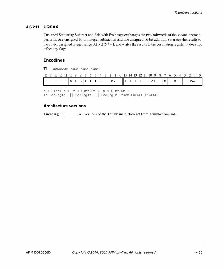
Thumb Instructions
4.6.211 UQSAX
Unsigned Saturating Subtract and Add with Exchange exchanges the two halfwords of the second operand, performs one unsigned 16-bit integer subtraction and one unsigned 16-bit addition, saturates the results to the 16-bit unsigned integer range 0 ≤ x ≤ 216 – 1, and writes the results to the destination register. It does not affect any flags.
Encodings
d = UInt(Rd); n = UInt(Rn); m = UInt(Rm);if BadReg(d) || BadReg(n) || BadReg(m) then UNPREDICTABLE;
Architecture versions
Encoding T1 All versions of the Thumb instruction set from Thumb-2 onwards.
T1 UQSAX<c> <Rd>,<Rn>,<Rm>
15 14 13 12 11 10 9 8 7 6 5 4 3 2 1 0 15 14 13 12 11 10 9 8 7 6 5 4 3 2 1 0
1 1 1 1 1 0 1 0 1 1 1 0 Rn 1 1 1 1 Rd 0 1 0 1 Rm
ARM DDI 0308D Copyright © 2004, 2005 ARM Limited. All rights reserved. 4-435

Thumb Instructions
Assembler syntax
UQSAX<c><q> {<Rd>,} <Rn>, <Rm>
where:
<c><q> See Standard assembler syntax fields on page 4-6.
<Rd> Specifies the destination register. If <Rd> is omitted, this register is the same as <Rn>.
<Rn> Specifies the register that contains the first operand.
<Rm> Specifies the register that contains the second operand.
Operation
if ConditionPassed() then EncodingSpecificOperations(); sum = UInt(R[n]<15:0>) + UInt(R[m]<31:16>); diff = UInt(R[n]<31:16>) - UInt(R[m]<15:0>); R[d]<15:0> = UnsignedSat(sum, 16); R[d]<31:16> = UnsignedSat(diff, 16);
Exceptions
None.
4-436 Copyright © 2004, 2005 ARM Limited. All rights reserved. ARM DDI 0308D

Thumb Instructions
4.6.212 UQSUB16
Unsigned Saturating Subtract 16 performs two unsigned 16-bit integer subtractions, saturates the results to the 16-bit unsigned integer range 0 ≤ x ≤ 216 – 1, and writes the results to the destination register. It does not affect any flags.
Encodings
d = UInt(Rd); n = UInt(Rn); m = UInt(Rm);if BadReg(d) || BadReg(n) || BadReg(m) then UNPREDICTABLE;
Architecture versions
Encoding T1 All versions of the Thumb instruction set from Thumb-2 onwards.
T1 UQSUB16<c> <Rd>,<Rn>,<Rm>
15 14 13 12 11 10 9 8 7 6 5 4 3 2 1 0 15 14 13 12 11 10 9 8 7 6 5 4 3 2 1 0
1 1 1 1 1 0 1 0 1 1 0 1 Rn 1 1 1 1 Rd 0 1 0 1 Rm
ARM DDI 0308D Copyright © 2004, 2005 ARM Limited. All rights reserved. 4-437
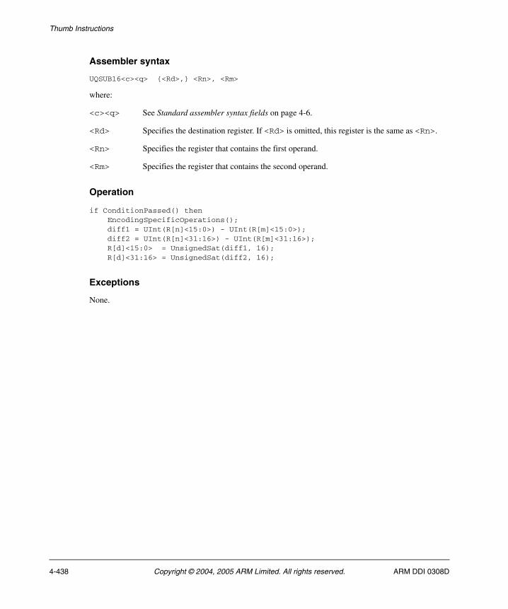
Thumb Instructions
Assembler syntax
UQSUB16<c><q> {<Rd>,} <Rn>, <Rm>
where:
<c><q> See Standard assembler syntax fields on page 4-6.
<Rd> Specifies the destination register. If <Rd> is omitted, this register is the same as <Rn>.
<Rn> Specifies the register that contains the first operand.
<Rm> Specifies the register that contains the second operand.
Operation
if ConditionPassed() then EncodingSpecificOperations(); diff1 = UInt(R[n]<15:0>) - UInt(R[m]<15:0>); diff2 = UInt(R[n]<31:16>) - UInt(R[m]<31:16>); R[d]<15:0> = UnsignedSat(diff1, 16); R[d]<31:16> = UnsignedSat(diff2, 16);
Exceptions
None.
4-438 Copyright © 2004, 2005 ARM Limited. All rights reserved. ARM DDI 0308D
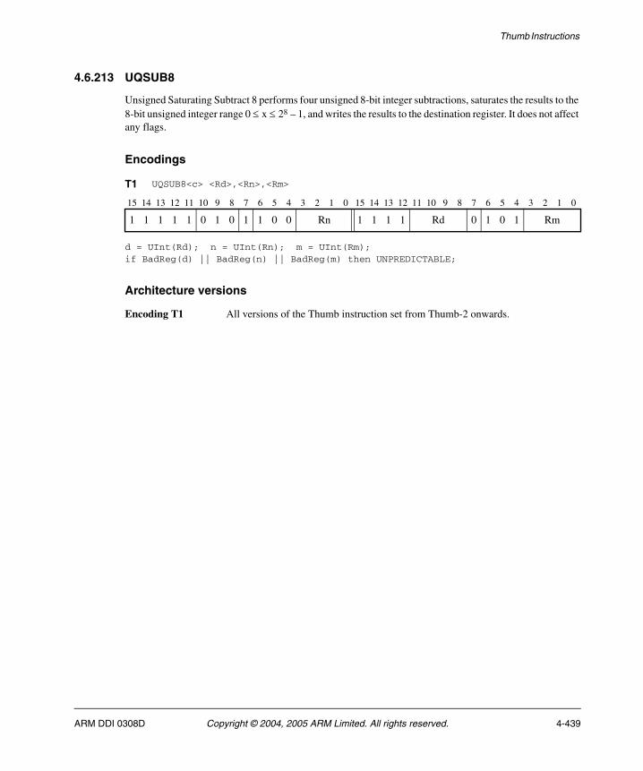
Thumb Instructions
4.6.213 UQSUB8
Unsigned Saturating Subtract 8 performs four unsigned 8-bit integer subtractions, saturates the results to the 8-bit unsigned integer range 0 ≤ x ≤ 28 – 1, and writes the results to the destination register. It does not affect any flags.
Encodings
d = UInt(Rd); n = UInt(Rn); m = UInt(Rm);if BadReg(d) || BadReg(n) || BadReg(m) then UNPREDICTABLE;
Architecture versions
Encoding T1 All versions of the Thumb instruction set from Thumb-2 onwards.
T1 UQSUB8<c> <Rd>,<Rn>,<Rm>
15 14 13 12 11 10 9 8 7 6 5 4 3 2 1 0 15 14 13 12 11 10 9 8 7 6 5 4 3 2 1 0
1 1 1 1 1 0 1 0 1 1 0 0 Rn 1 1 1 1 Rd 0 1 0 1 Rm
ARM DDI 0308D Copyright © 2004, 2005 ARM Limited. All rights reserved. 4-439
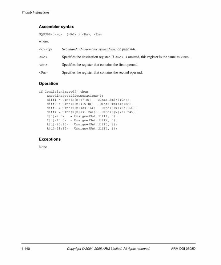
Thumb Instructions
Assembler syntax
UQSUB8<c><q> {<Rd>,} <Rn>, <Rm>
where:
<c><q> See Standard assembler syntax fields on page 4-6.
<Rd> Specifies the destination register. If <Rd> is omitted, this register is the same as <Rn>.
<Rn> Specifies the register that contains the first operand.
<Rm> Specifies the register that contains the second operand.
Operation
if ConditionPassed() then EncodingSpecificOperations(); diff1 = UInt(R[n]<7:0>) - UInt(R[m]<7:0>); diff2 = UInt(R[n]<15:8>) - UInt(R[m]<15:8>); diff3 = UInt(R[n]<23:16>) - UInt(R[m]<23:16>); diff4 = UInt(R[n]<31:24>) - UInt(R[m]<31:24>); R[d]<7:0> = UnsignedSat(diff1, 8); R[d]<15:8> = UnsignedSat(diff2, 8); R[d]<23:16> = UnsignedSat(diff3, 8); R[d]<31:24> = UnsignedSat(diff4, 8);
Exceptions
None.
4-440 Copyright © 2004, 2005 ARM Limited. All rights reserved. ARM DDI 0308D
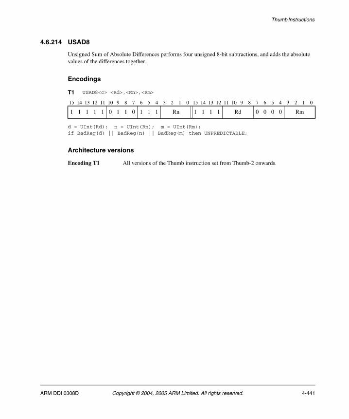
Thumb Instructions
4.6.214 USAD8
Unsigned Sum of Absolute Differences performs four unsigned 8-bit subtractions, and adds the absolute values of the differences together.
Encodings
d = UInt(Rd); n = UInt(Rn); m = UInt(Rm);if BadReg(d) || BadReg(n) || BadReg(m) then UNPREDICTABLE;
Architecture versions
Encoding T1 All versions of the Thumb instruction set from Thumb-2 onwards.
T1 USAD8<c> <Rd>,<Rn>,<Rm>
15 14 13 12 11 10 9 8 7 6 5 4 3 2 1 0 15 14 13 12 11 10 9 8 7 6 5 4 3 2 1 0
1 1 1 1 1 0 1 1 0 1 1 1 Rn 1 1 1 1 Rd 0 0 0 0 Rm
ARM DDI 0308D Copyright © 2004, 2005 ARM Limited. All rights reserved. 4-441
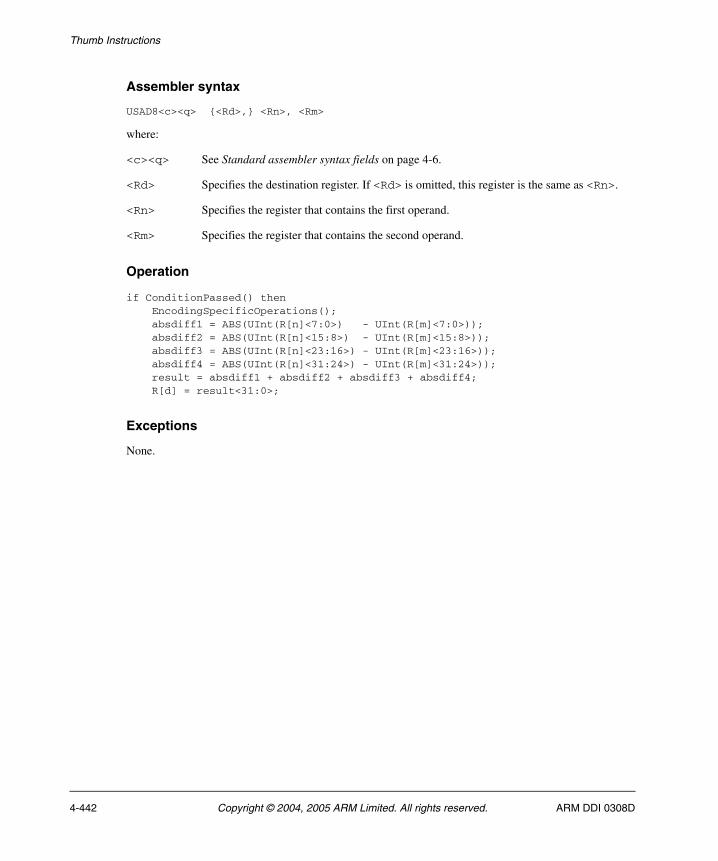
Thumb Instructions
Assembler syntax
USAD8<c><q> {<Rd>,} <Rn>, <Rm>
where:
<c><q> See Standard assembler syntax fields on page 4-6.
<Rd> Specifies the destination register. If <Rd> is omitted, this register is the same as <Rn>.
<Rn> Specifies the register that contains the first operand.
<Rm> Specifies the register that contains the second operand.
Operation
if ConditionPassed() then EncodingSpecificOperations(); absdiff1 = ABS(UInt(R[n]<7:0>) - UInt(R[m]<7:0>)); absdiff2 = ABS(UInt(R[n]<15:8>) - UInt(R[m]<15:8>)); absdiff3 = ABS(UInt(R[n]<23:16>) - UInt(R[m]<23:16>)); absdiff4 = ABS(UInt(R[n]<31:24>) - UInt(R[m]<31:24>)); result = absdiff1 + absdiff2 + absdiff3 + absdiff4; R[d] = result<31:0>;
Exceptions
None.
4-442 Copyright © 2004, 2005 ARM Limited. All rights reserved. ARM DDI 0308D
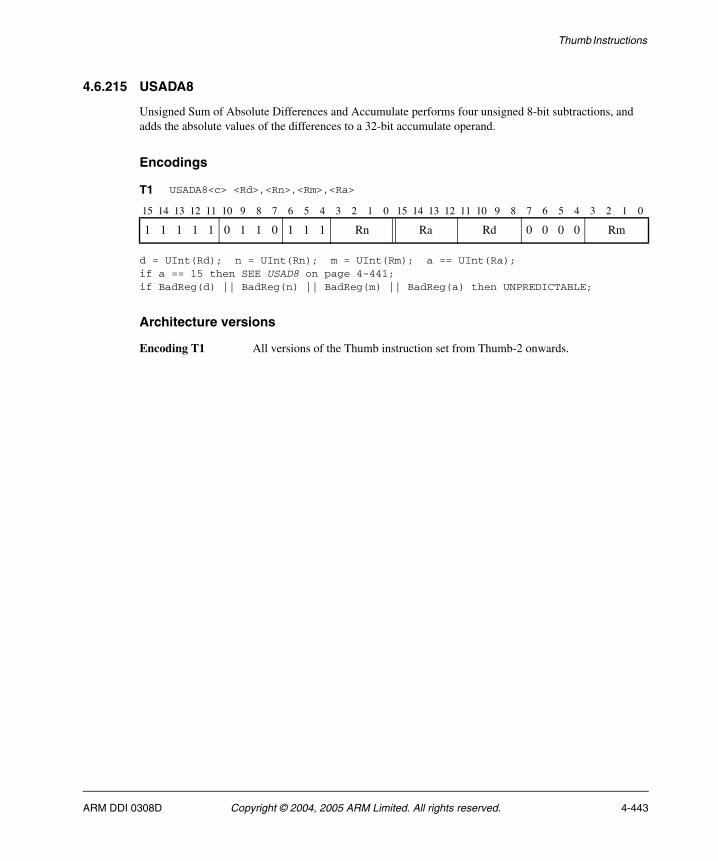
Thumb Instructions
4.6.215 USADA8
Unsigned Sum of Absolute Differences and Accumulate performs four unsigned 8-bit subtractions, and adds the absolute values of the differences to a 32-bit accumulate operand.
Encodings
d = UInt(Rd); n = UInt(Rn); m = UInt(Rm); a == UInt(Ra);if a == 15 then SEE USAD8 on page 4-441;if BadReg(d) || BadReg(n) || BadReg(m) || BadReg(a) then UNPREDICTABLE;
Architecture versions
Encoding T1 All versions of the Thumb instruction set from Thumb-2 onwards.
T1 USADA8<c> <Rd>,<Rn>,<Rm>,<Ra>
15 14 13 12 11 10 9 8 7 6 5 4 3 2 1 0 15 14 13 12 11 10 9 8 7 6 5 4 3 2 1 0
1 1 1 1 1 0 1 1 0 1 1 1 Rn Ra Rd 0 0 0 0 Rm
ARM DDI 0308D Copyright © 2004, 2005 ARM Limited. All rights reserved. 4-443
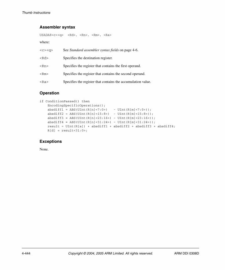
Thumb Instructions
Assembler syntax
USADA8<c><q> <Rd>, <Rn>, <Rm>, <Ra>
where:
<c><q> See Standard assembler syntax fields on page 4-6.
<Rd> Specifies the destination register.
<Rn> Specifies the register that contains the first operand.
<Rm> Specifies the register that contains the second operand.
<Ra> Specifies the register that contains the accumulation value.
Operation
if ConditionPassed() then EncodingSpecificOperations(); absdiff1 = ABS(UInt(R[n]<7:0>) - UInt(R[m]<7:0>)); absdiff2 = ABS(UInt(R[n]<15:8>) - UInt(R[m]<15:8>)); absdiff3 = ABS(UInt(R[n]<23:16>) - UInt(R[m]<23:16>)); absdiff4 = ABS(UInt(R[n]<31:24>) - UInt(R[m]<31:24>)); result = UInt(R[a]) + absdiff1 + absdiff2 + absdiff3 + absdiff4; R[d] = result<31:0>;
Exceptions
None.
4-444 Copyright © 2004, 2005 ARM Limited. All rights reserved. ARM DDI 0308D
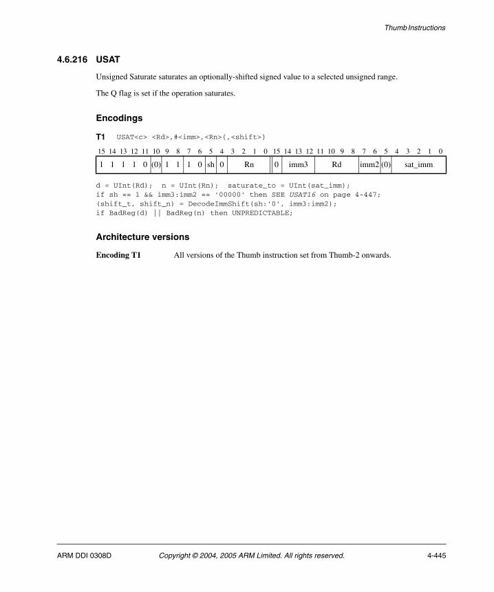
Thumb Instructions
4.6.216 USAT
Unsigned Saturate saturates an optionally-shifted signed value to a selected unsigned range.
The Q flag is set if the operation saturates.
Encodings
d = UInt(Rd); n = UInt(Rn); saturate_to = UInt(sat_imm);if sh == 1 && imm3:imm2 == '00000' then SEE USAT16 on page 4-447;(shift_t, shift_n) = DecodeImmShift(sh:'0', imm3:imm2);if BadReg(d) || BadReg(n) then UNPREDICTABLE;
Architecture versions
Encoding T1 All versions of the Thumb instruction set from Thumb-2 onwards.
T1 USAT<c> <Rd>,#<imm>,<Rn>{,<shift>}
15 14 13 12 11 10 9 8 7 6 5 4 3 2 1 0 15 14 13 12 11 10 9 8 7 6 5 4 3 2 1 0
1 1 1 1 0 (0) 1 1 1 0 sh 0 Rn 0 imm3 Rd imm2 (0) sat_imm
ARM DDI 0308D Copyright © 2004, 2005 ARM Limited. All rights reserved. 4-445
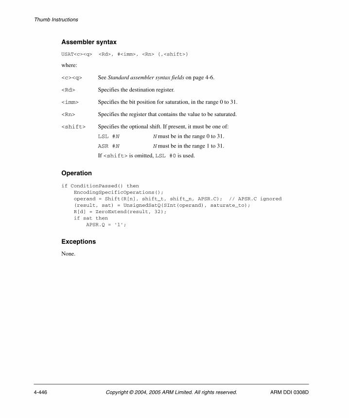
Thumb Instructions
Assembler syntax
USAT<c><q> <Rd>, #<imm>, <Rn> {,<shift>}
where:
<c><q> See Standard assembler syntax fields on page 4-6.
<Rd> Specifies the destination register.
<imm> Specifies the bit position for saturation, in the range 0 to 31.
<Rn> Specifies the register that contains the value to be saturated.
<shift> Specifies the optional shift. If present, it must be one of:
LSL #N N must be in the range 0 to 31.
ASR #N N must be in the range 1 to 31.
If <shift> is omitted, LSL #0 is used.
Operation
if ConditionPassed() then EncodingSpecificOperations(); operand = Shift(R[n], shift_t, shift_n, APSR.C); // APSR.C ignored (result, sat) = UnsignedSatQ(SInt(operand), saturate_to); R[d] = ZeroExtend(result, 32); if sat then APSR.Q = '1';
Exceptions
None.
4-446 Copyright © 2004, 2005 ARM Limited. All rights reserved. ARM DDI 0308D
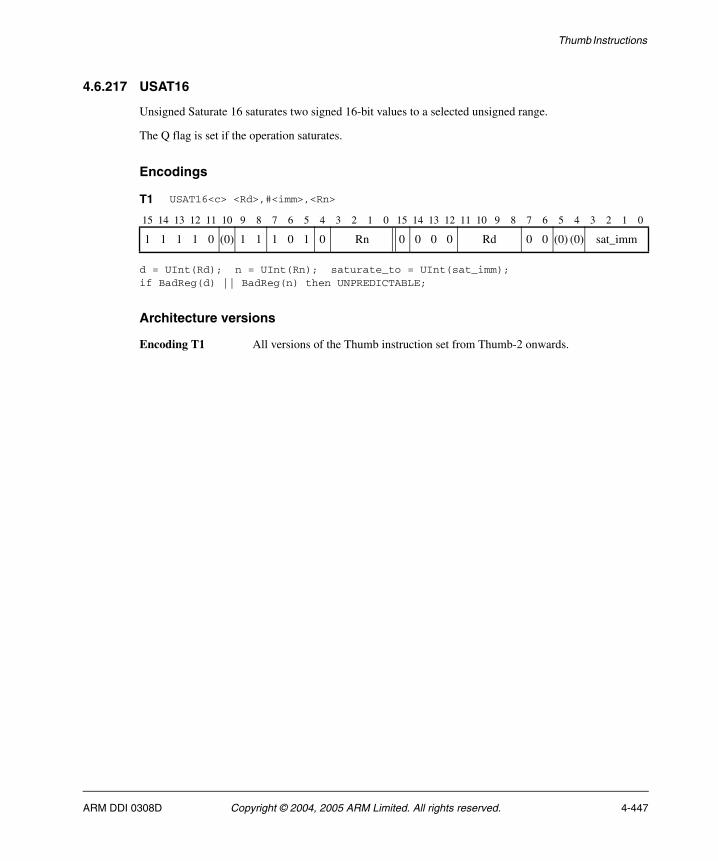
Thumb Instructions
4.6.217 USAT16
Unsigned Saturate 16 saturates two signed 16-bit values to a selected unsigned range.
The Q flag is set if the operation saturates.
Encodings
d = UInt(Rd); n = UInt(Rn); saturate_to = UInt(sat_imm);if BadReg(d) || BadReg(n) then UNPREDICTABLE;
Architecture versions
Encoding T1 All versions of the Thumb instruction set from Thumb-2 onwards.
T1 USAT16<c> <Rd>,#<imm>,<Rn>
15 14 13 12 11 10 9 8 7 6 5 4 3 2 1 0 15 14 13 12 11 10 9 8 7 6 5 4 3 2 1 0
1 1 1 1 0 (0) 1 1 1 0 1 0 Rn 0 0 0 0 Rd 0 0 (0) (0) sat_imm
ARM DDI 0308D Copyright © 2004, 2005 ARM Limited. All rights reserved. 4-447
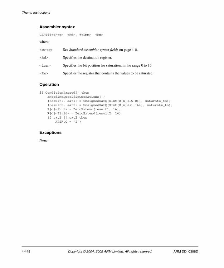
Thumb Instructions
Assembler syntax
USAT16<c><q> <Rd>, #<imm>, <Rn>
where:
<c><q> See Standard assembler syntax fields on page 4-6.
<Rd> Specifies the destination register.
<imm> Specifies the bit position for saturation, in the range 0 to 15.
<Rn> Specifies the register that contains the values to be saturated.
Operation
if ConditionPassed() then EncodingSpecificOperations(); (result1, sat1) = UnsignedSatQ(SInt(R[n]<15:0>), saturate_to); (result2, sat2) = UnsignedSatQ(SInt(R[n]<31:16>), saturate_to); R[d]<15:0> = ZeroExtend(result1, 16); R[d]<31:16> = ZeroExtend(result2, 16); if sat1 || sat2 then APSR.Q = '1';
Exceptions
None.
4-448 Copyright © 2004, 2005 ARM Limited. All rights reserved. ARM DDI 0308D

Thumb Instructions
4.6.218 USAX
Unsigned Subtract and Add with Exchange exchanges the two halfwords of the second operand, performs one unsigned 16-bit integer subtraction and one unsigned 16-bit addition, and writes the results to the destination register. It sets the GE bits in the APSR according to the results.
Encodings
d = UInt(Rd); n = UInt(Rn); m = UInt(Rm);if BadReg(d) || BadReg(n) || BadReg(m) then UNPREDICTABLE;
Architecture versions
Encoding T1 All versions of the Thumb instruction set from Thumb-2 onwards.
T1 USAX<c> <Rd>,<Rn>,<Rm>
15 14 13 12 11 10 9 8 7 6 5 4 3 2 1 0 15 14 13 12 11 10 9 8 7 6 5 4 3 2 1 0
1 1 1 1 1 0 1 0 1 1 1 0 Rn 1 1 1 1 Rd 0 1 0 0 Rm
ARM DDI 0308D Copyright © 2004, 2005 ARM Limited. All rights reserved. 4-449

Thumb Instructions
Assembler syntax
USAX<c><q> {<Rd>,} <Rn>, <Rm>
where:
<c><q> See Standard assembler syntax fields on page 4-6.
<Rd> Specifies the destination register. If <Rd> is omitted, this register is the same as <Rn>.
<Rn> Specifies the register that contains the first operand.
<Rm> Specifies the register that contains the second operand.
Operation
if ConditionPassed() then EncodingSpecificOperations(); sum = UInt(R[n]<15:0>) + UInt(R[m]<31:16>); diff = UInt(R[n]<31:16>) - UInt(R[m]<15:0>); R[d]<15:0> = sum<15:0>; R[d]<31:16> = diff<15:0>; APSR.GE<1:0> = if sum >= 0x10000 then '11' else '00'; APSR.GE<3:2> = if diff >= 0 then '11' else '00';
Exceptions
None.
4-450 Copyright © 2004, 2005 ARM Limited. All rights reserved. ARM DDI 0308D
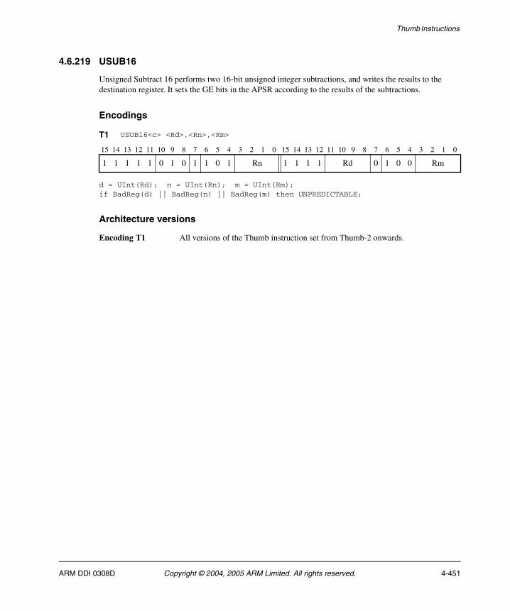
Thumb Instructions
4.6.219 USUB16
Unsigned Subtract 16 performs two 16-bit unsigned integer subtractions, and writes the results to the destination register. It sets the GE bits in the APSR according to the results of the subtractions.
Encodings
d = UInt(Rd); n = UInt(Rn); m = UInt(Rm);if BadReg(d) || BadReg(n) || BadReg(m) then UNPREDICTABLE;
Architecture versions
Encoding T1 All versions of the Thumb instruction set from Thumb-2 onwards.
T1 USUB16<c> <Rd>,<Rn>,<Rm>
15 14 13 12 11 10 9 8 7 6 5 4 3 2 1 0 15 14 13 12 11 10 9 8 7 6 5 4 3 2 1 0
1 1 1 1 1 0 1 0 1 1 0 1 Rn 1 1 1 1 Rd 0 1 0 0 Rm
ARM DDI 0308D Copyright © 2004, 2005 ARM Limited. All rights reserved. 4-451
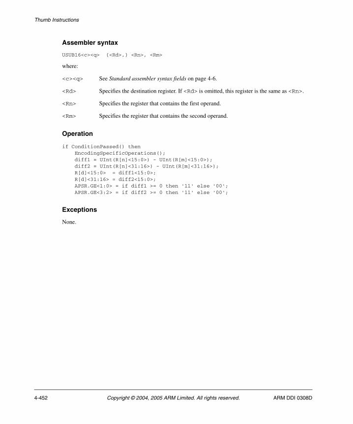
Thumb Instructions
Assembler syntax
USUB16<c><q> {<Rd>,} <Rn>, <Rm>
where:
<c><q> See Standard assembler syntax fields on page 4-6.
<Rd> Specifies the destination register. If <Rd> is omitted, this register is the same as <Rn>.
<Rn> Specifies the register that contains the first operand.
<Rm> Specifies the register that contains the second operand.
Operation
if ConditionPassed() then EncodingSpecificOperations(); diff1 = UInt(R[n]<15:0>) - UInt(R[m]<15:0>); diff2 = UInt(R[n]<31:16>) - UInt(R[m]<31:16>); R[d]<15:0> = diff1<15:0>; R[d]<31:16> = diff2<15:0>; APSR.GE<1:0> = if diff1 >= 0 then '11' else '00'; APSR.GE<3:2> = if diff2 >= 0 then '11' else '00';
Exceptions
None.
4-452 Copyright © 2004, 2005 ARM Limited. All rights reserved. ARM DDI 0308D

Thumb Instructions
4.6.220 USUB8
Unsigned Subtract 8 performs four 8-bit unsigned integer subtractions, and writes the results to the destination register. It sets the GE bits in the APSR according to the results of the subtractions.
Encodings
d = UInt(Rd); n = UInt(Rn); m = UInt(Rm);if BadReg(d) || BadReg(n) || BadReg(m) then UNPREDICTABLE;
Architecture versions
Encoding T1 All versions of the Thumb instruction set from Thumb-2 onwards.
T1 USUB8<c> <Rd>,<Rn>,<Rm>
15 14 13 12 11 10 9 8 7 6 5 4 3 2 1 0 15 14 13 12 11 10 9 8 7 6 5 4 3 2 1 0
1 1 1 1 1 0 1 0 1 1 0 0 Rn 1 1 1 1 Rd 0 1 0 0 Rm
ARM DDI 0308D Copyright © 2004, 2005 ARM Limited. All rights reserved. 4-453
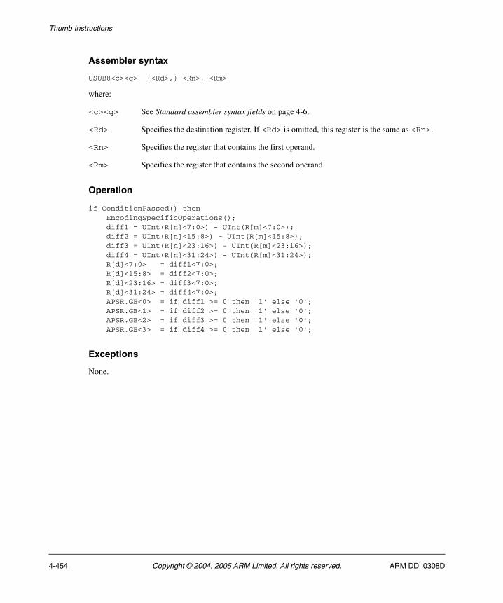
Thumb Instructions
Assembler syntax
USUB8<c><q> {<Rd>,} <Rn>, <Rm>
where:
<c><q> See Standard assembler syntax fields on page 4-6.
<Rd> Specifies the destination register. If <Rd> is omitted, this register is the same as <Rn>.
<Rn> Specifies the register that contains the first operand.
<Rm> Specifies the register that contains the second operand.
Operation
if ConditionPassed() then EncodingSpecificOperations(); diff1 = UInt(R[n]<7:0>) - UInt(R[m]<7:0>); diff2 = UInt(R[n]<15:8>) - UInt(R[m]<15:8>); diff3 = UInt(R[n]<23:16>) - UInt(R[m]<23:16>); diff4 = UInt(R[n]<31:24>) - UInt(R[m]<31:24>); R[d]<7:0> = diff1<7:0>; R[d]<15:8> = diff2<7:0>; R[d]<23:16> = diff3<7:0>; R[d]<31:24> = diff4<7:0>; APSR.GE<0> = if diff1 >= 0 then '1' else '0'; APSR.GE<1> = if diff2 >= 0 then '1' else '0'; APSR.GE<2> = if diff3 >= 0 then '1' else '0'; APSR.GE<3> = if diff4 >= 0 then '1' else '0';
Exceptions
None.
4-454 Copyright © 2004, 2005 ARM Limited. All rights reserved. ARM DDI 0308D

Thumb Instructions
4.6.221 UXTAB
Unsigned Extend and Add Byte extracts an 8-bit value from a register, zero extends it to 32 bits, adds the result to the value in another register, and writes the final result to the destination register. You can specify a rotation by 0, 8, 16, or 24 bits before extracting the 8-bit value.
Encodings
d = UInt(Rd); n = UInt(Rn); m = UInt(Rm); rotation = UInt(rotate:'000');if n == 15 then SEE UXTB on page 4-461;if BadReg(d) || n == 13 || BadReg(m) then UNPREDICTABLE;
Architecture versions
Encoding T1 All versions of the Thumb instruction set from Thumb-2 onwards.
T1 UXTAB<c> <Rd>,<Rn>,<Rm>{,<rotation>}
15 14 13 12 11 10 9 8 7 6 5 4 3 2 1 0 15 14 13 12 11 10 9 8 7 6 5 4 3 2 1 0
1 1 1 1 1 0 1 0 0 1 0 1 Rn 1 1 1 1 Rd 1 (0) rotate Rm
ARM DDI 0308D Copyright © 2004, 2005 ARM Limited. All rights reserved. 4-455
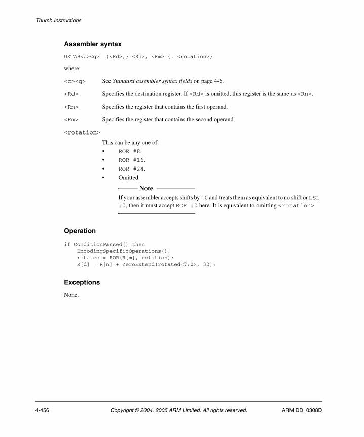
Thumb Instructions
Assembler syntax
UXTAB<c><q> {<Rd>,} <Rn>, <Rm> {, <rotation>}
where:
<c><q> See Standard assembler syntax fields on page 4-6.
<Rd> Specifies the destination register. If <Rd> is omitted, this register is the same as <Rn>.
<Rn> Specifies the register that contains the first operand.
<Rm> Specifies the register that contains the second operand.
<rotation>
This can be any one of:
• ROR #8.
• ROR #16.
• ROR #24.
• Omitted.
Note If your assembler accepts shifts by #0 and treats them as equivalent to no shift or LSL
#0, then it must accept ROR #0 here. It is equivalent to omitting <rotation>.
Operation
if ConditionPassed() then EncodingSpecificOperations(); rotated = ROR(R[m], rotation); R[d] = R[n] + ZeroExtend(rotated<7:0>, 32);
Exceptions
None.
4-456 Copyright © 2004, 2005 ARM Limited. All rights reserved. ARM DDI 0308D

Thumb Instructions
4.6.222 UXTAB16
Unsigned Extend and Add Byte 16 extracts two 8-bit values from a register, zero extends them to 16 bits each, adds the results to two 16-bit values from another register, and writes the final results to the destination register. You can specify a rotation by 0, 8, 16, or 24 bits before extracting the 8-bit values.
Encodings
d = UInt(Rd); n = UInt(Rn); m = UInt(Rm); rotation = UInt(rotate:'000');if n == 15 then SEE UXTB16 on page 4-463;if BadReg(d) || n == 13 || BadReg(m) then UNPREDICTABLE;
Architecture versions
Encoding T1 All versions of the Thumb instruction set from Thumb-2 onwards.
T1 UXTAB16<c> <Rd>,<Rn>,<Rm>{,<rotation>}
15 14 13 12 11 10 9 8 7 6 5 4 3 2 1 0 15 14 13 12 11 10 9 8 7 6 5 4 3 2 1 0
1 1 1 1 1 0 1 0 0 0 1 1 Rn 1 1 1 1 Rd 1 (0) rotate Rm
ARM DDI 0308D Copyright © 2004, 2005 ARM Limited. All rights reserved. 4-457

Thumb Instructions
Assembler syntax
UXTAB16<c><q> {<Rd>,} <Rn>, <Rm> {, <rotation>}
where:
<c><q> See Standard assembler syntax fields on page 4-6.
<Rd> Specifies the destination register. If <Rd> is omitted, this register is the same as <Rn>.
<Rn> Specifies the register that contains the first operand.
<Rm> Specifies the register that contains the second operand.
<rotation>
This can be any one of:
• ROR #8.
• ROR #16.
• ROR #24.
• Omitted.
Note If your assembler accepts shifts by #0 and treats them as equivalent to no shift or LSL
#0, then it must accept ROR #0 here. It is equivalent to omitting <rotation>.
Operation
if ConditionPassed() then EncodingSpecificOperations(); rotated = ROR(R[m], rotation); R[d]<15:0> = R[n]<15:0> + ZeroExtend(rotated<7:0>, 16); R[d]<31:16> = R[n]<31:16> + ZeroExtend(rotated<23:16>, 16);
Exceptions
None.
4-458 Copyright © 2004, 2005 ARM Limited. All rights reserved. ARM DDI 0308D
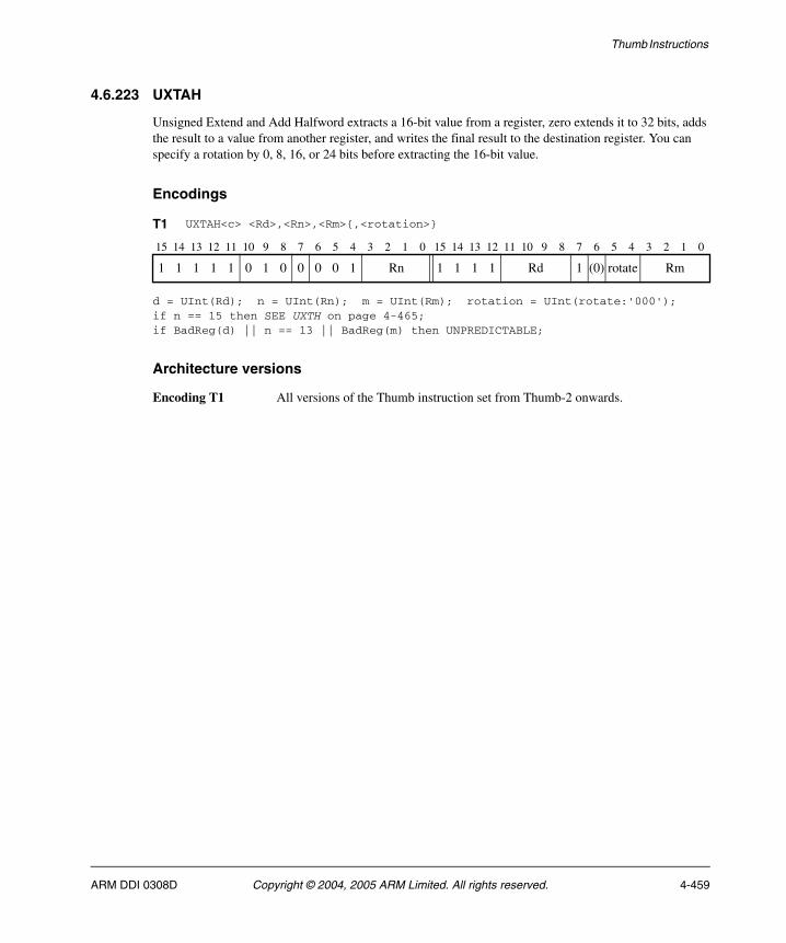
Thumb Instructions
4.6.223 UXTAH
Unsigned Extend and Add Halfword extracts a 16-bit value from a register, zero extends it to 32 bits, adds the result to a value from another register, and writes the final result to the destination register. You can specify a rotation by 0, 8, 16, or 24 bits before extracting the 16-bit value.
Encodings
d = UInt(Rd); n = UInt(Rn); m = UInt(Rm); rotation = UInt(rotate:'000');if n == 15 then SEE UXTH on page 4-465;if BadReg(d) || n == 13 || BadReg(m) then UNPREDICTABLE;
Architecture versions
Encoding T1 All versions of the Thumb instruction set from Thumb-2 onwards.
T1 UXTAH<c> <Rd>,<Rn>,<Rm>{,<rotation>}
15 14 13 12 11 10 9 8 7 6 5 4 3 2 1 0 15 14 13 12 11 10 9 8 7 6 5 4 3 2 1 0
1 1 1 1 1 0 1 0 0 0 0 1 Rn 1 1 1 1 Rd 1 (0) rotate Rm
ARM DDI 0308D Copyright © 2004, 2005 ARM Limited. All rights reserved. 4-459

Thumb Instructions
Assembler syntax
UXTAH<c><q> {<Rd>,} <Rn>, <Rm> {, <rotation>}
where:
<c><q> See Standard assembler syntax fields on page 4-6.
<Rd> Specifies the destination register. If <Rd> is omitted, this register is the same as <Rn>.
<Rn> Specifies the register that contains the first operand.
<Rm> Specifies the register that contains the second operand.
<rotation>
This can be any one of:
• ROR #8.
• ROR #16.
• ROR #24.
• Omitted.
Note If your assembler accepts shifts by #0 and treats them as equivalent to no shift or LSL
#0, then it must accept ROR #0 here. It is equivalent to omitting <rotation>.
Operation
if ConditionPassed() then EncodingSpecificOperations(); rotated = ROR(R[m], rotation); R[d] = R[n] + ZeroExtend(rotated<15:0>, 32);
Exceptions
None.
4-460 Copyright © 2004, 2005 ARM Limited. All rights reserved. ARM DDI 0308D

Thumb Instructions
4.6.224 UXTB
Unsigned Extend Byte extracts an 8-bit value from a register, zero extends it to 32 bits, and writes the result to the destination register. You can specify a rotation by 0, 8, 16, or 24 bits before extracting the 8-bit value.
Encodings
d = UInt(Rd); m = UInt(Rm); rotation = 0;
d = UInt(Rd); m = UInt(Rm); rotation = UInt(rotate:'000');if BadReg(d) || BadReg(m) then UNPREDICTABLE;
Architecture versions
Encoding T1 All versions of the Thumb instruction set from ARMv6 onwards.
Encoding T2 All versions of the Thumb instruction set from Thumb-2 onwards.
T1 UXTB<c> <Rd>,<Rm>
15 14 13 12 11 10 9 8 7 6 5 4 3 2 1 0
1 0 1 1 0 0 1 0 1 1 Rm Rd
T2 UXTB<c> <Rd>,<Rm>{,<rotation>}
15 14 13 12 11 10 9 8 7 6 5 4 3 2 1 0 15 14 13 12 11 10 9 8 7 6 5 4 3 2 1 0
1 1 1 1 1 0 1 0 0 1 0 1 1 1 1 1 1 1 1 1 Rd 1 (0) rotate Rm
ARM DDI 0308D Copyright © 2004, 2005 ARM Limited. All rights reserved. 4-461
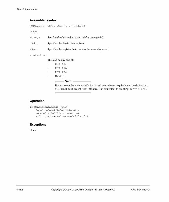
Thumb Instructions
Assembler syntax
UXTB<c><q> <Rd>, <Rm> {, <rotation>}
where:
<c><q> See Standard assembler syntax fields on page 4-6.
<Rd> Specifies the destination register.
<Rm> Specifies the register that contains the second operand.
<rotation>
This can be any one of:
• ROR #8.
• ROR #16.
• ROR #24.
• Omitted.
Note If your assembler accepts shifts by #0 and treats them as equivalent to no shift or LSL
#0, then it must accept ROR #0 here. It is equivalent to omitting <rotation>.
Operation
if ConditionPassed() then EncodingSpecificOperations(); rotated = ROR(R[m], rotation); R[d] = ZeroExtend(rotated<7:0>, 32);
Exceptions
None.
4-462 Copyright © 2004, 2005 ARM Limited. All rights reserved. ARM DDI 0308D
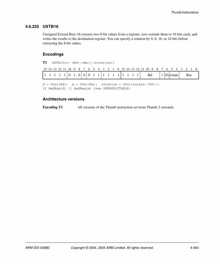
Thumb Instructions
4.6.225 UXTB16
Unsigned Extend Byte 16 extracts two 8-bit values from a register, zero extends them to 16 bits each, and writes the results to the destination register. You can specify a rotation by 0, 8, 16, or 24 bits before extracting the 8-bit values.
Encodings
d = UInt(Rd); m = UInt(Rm); rotation = UInt(rotate:'000');if BadReg(d) || BadReg(m) then UNPREDICTABLE;
Architecture versions
Encoding T1 All versions of the Thumb instruction set from Thumb-2 onwards.
T1 UXTB16<c> <Rd>,<Rm>{,<rotation>}
15 14 13 12 11 10 9 8 7 6 5 4 3 2 1 0 15 14 13 12 11 10 9 8 7 6 5 4 3 2 1 0
1 1 1 1 1 0 1 0 0 0 1 1 1 1 1 1 1 1 1 1 Rd 1 (0) rotate Rm
ARM DDI 0308D Copyright © 2004, 2005 ARM Limited. All rights reserved. 4-463
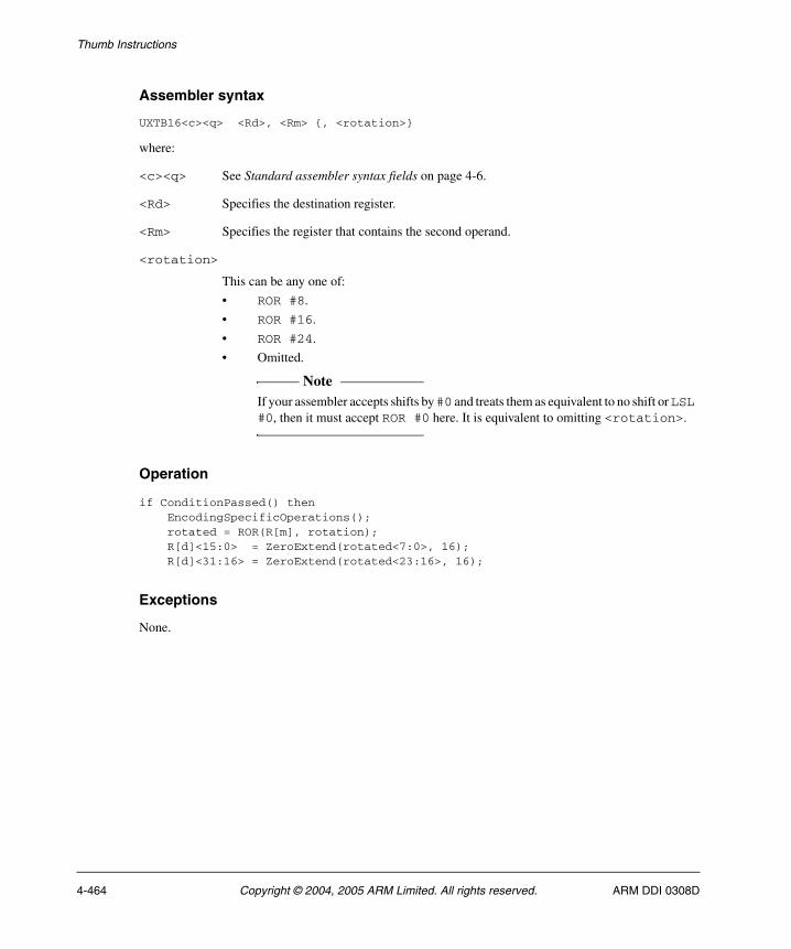
Thumb Instructions
Assembler syntax
UXTB16<c><q> <Rd>, <Rm> {, <rotation>}
where:
<c><q> See Standard assembler syntax fields on page 4-6.
<Rd> Specifies the destination register.
<Rm> Specifies the register that contains the second operand.
<rotation>
This can be any one of:
• ROR #8.
• ROR #16.
• ROR #24.
• Omitted.
Note If your assembler accepts shifts by #0 and treats them as equivalent to no shift or LSL
#0, then it must accept ROR #0 here. It is equivalent to omitting <rotation>.
Operation
if ConditionPassed() then EncodingSpecificOperations(); rotated = ROR(R[m], rotation); R[d]<15:0> = ZeroExtend(rotated<7:0>, 16); R[d]<31:16> = ZeroExtend(rotated<23:16>, 16);
Exceptions
None.
4-464 Copyright © 2004, 2005 ARM Limited. All rights reserved. ARM DDI 0308D
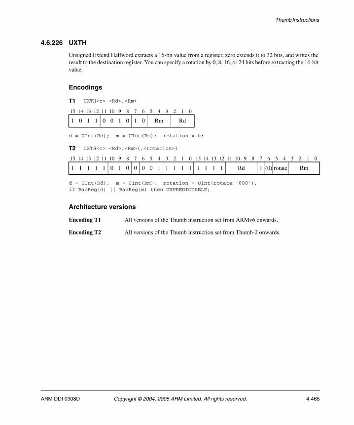
Thumb Instructions
4.6.226 UXTH
Unsigned Extend Halfword extracts a 16-bit value from a register, zero extends it to 32 bits, and writes the result to the destination register. You can specify a rotation by 0, 8, 16, or 24 bits before extracting the 16-bit value.
Encodings
d = UInt(Rd); m = UInt(Rm); rotation = 0;
d = UInt(Rd); m = UInt(Rm); rotation = UInt(rotate:'000');if BadReg(d) || BadReg(m) then UNPREDICTABLE;
Architecture versions
Encoding T1 All versions of the Thumb instruction set from ARMv6 onwards.
Encoding T2 All versions of the Thumb instruction set from Thumb-2 onwards.
T1 UXTH<c> <Rd>,<Rm>
15 14 13 12 11 10 9 8 7 6 5 4 3 2 1 0
1 0 1 1 0 0 1 0 1 0 Rm Rd
T2 UXTH<c> <Rd>,<Rm>{,<rotation>}
15 14 13 12 11 10 9 8 7 6 5 4 3 2 1 0 15 14 13 12 11 10 9 8 7 6 5 4 3 2 1 0
1 1 1 1 1 0 1 0 0 0 0 1 1 1 1 1 1 1 1 1 Rd 1 (0) rotate Rm
ARM DDI 0308D Copyright © 2004, 2005 ARM Limited. All rights reserved. 4-465

Thumb Instructions
Assembler syntax
UXTH<c><q> <Rd>, <Rm> {, <rotation>}
where:
<c><q> See Standard assembler syntax fields on page 4-6.
<Rd> Specifies the destination register.
<Rm> Specifies the register that contains the second operand.
<rotation>
This can be any one of:
• ROR #8.
• ROR #16.
• ROR #24.
• Omitted.
Note If your assembler accepts shifts by #0 and treats them as equivalent to no shift or LSL
#0, then it must accept ROR #0 here. It is equivalent to omitting <rotation>.
Operation
if ConditionPassed() then EncodingSpecificOperations(); rotated = ROR(R[m], rotation); R[d] = ZeroExtend(rotated<15:0>, 32);
Exceptions
None.
4-466 Copyright © 2004, 2005 ARM Limited. All rights reserved. ARM DDI 0308D
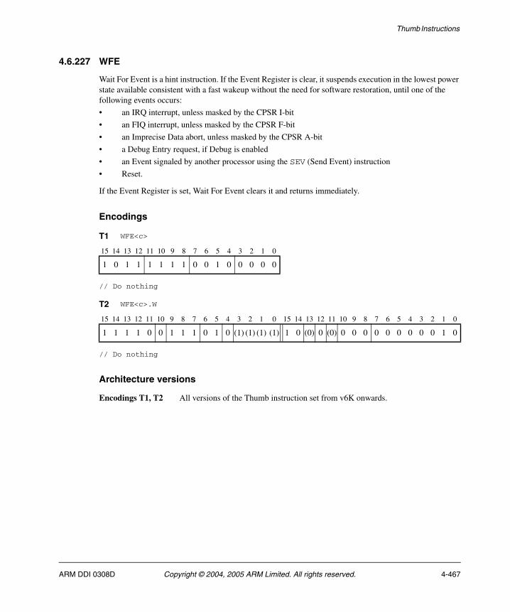
Thumb Instructions
4.6.227 WFE
Wait For Event is a hint instruction. If the Event Register is clear, it suspends execution in the lowest power state available consistent with a fast wakeup without the need for software restoration, until one of the following events occurs:
• an IRQ interrupt, unless masked by the CPSR I-bit
• an FIQ interrupt, unless masked by the CPSR F-bit
• an Imprecise Data abort, unless masked by the CPSR A-bit
• a Debug Entry request, if Debug is enabled
• an Event signaled by another processor using the SEV (Send Event) instruction
• Reset.
If the Event Register is set, Wait For Event clears it and returns immediately.
Encodings
// Do nothing
// Do nothing
Architecture versions
Encodings T1, T2 All versions of the Thumb instruction set from v6K onwards.
T1 WFE<c>
15 14 13 12 11 10 9 8 7 6 5 4 3 2 1 0
1 0 1 1 1 1 1 1 0 0 1 0 0 0 0 0
T2 WFE<c>.W
15 14 13 12 11 10 9 8 7 6 5 4 3 2 1 0 15 14 13 12 11 10 9 8 7 6 5 4 3 2 1 0
1 1 1 1 0 0 1 1 1 0 1 0 (1) (1) (1) (1) 1 0 (0) 0 (0) 0 0 0 0 0 0 0 0 0 1 0
ARM DDI 0308D Copyright © 2004, 2005 ARM Limited. All rights reserved. 4-467
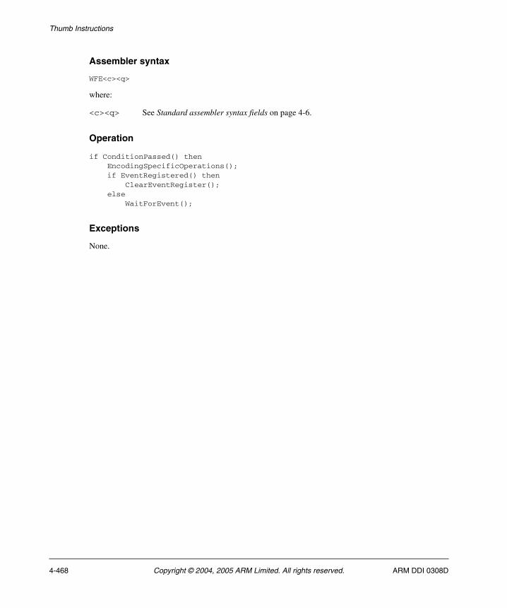
Thumb Instructions
Assembler syntax
WFE<c><q>
where:
<c><q> See Standard assembler syntax fields on page 4-6.
Operation
if ConditionPassed() then EncodingSpecificOperations(); if EventRegistered() then ClearEventRegister(); else WaitForEvent();
Exceptions
None.
4-468 Copyright © 2004, 2005 ARM Limited. All rights reserved. ARM DDI 0308D
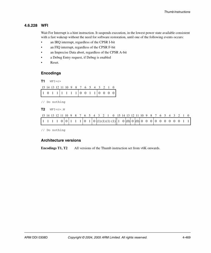
Thumb Instructions
4.6.228 WFI
Wait For Interrupt is a hint instruction. It suspends execution, in the lowest power state available consistent with a fast wakeup without the need for software restoration, until one of the following events occurs:
• an IRQ interrupt, regardless of the CPSR I-bit
• an FIQ interrupt, regardless of the CPSR F-bit
• an Imprecise Data abort, regardless of the CPSR A-bit
• a Debug Entry request, if Debug is enabled
• Reset.
Encodings
// Do nothing
// Do nothing
Architecture versions
Encodings T1, T2 All versions of the Thumb instruction set from v6K onwards.
T1 WFI<c>
15 14 13 12 11 10 9 8 7 6 5 4 3 2 1 0
1 0 1 1 1 1 1 1 0 0 1 1 0 0 0 0
T2 WFI<c>.W
15 14 13 12 11 10 9 8 7 6 5 4 3 2 1 0 15 14 13 12 11 10 9 8 7 6 5 4 3 2 1 0
1 1 1 1 0 0 1 1 1 0 1 0 (1) (1) (1) (1) 1 0 (0) 0 (0) 0 0 0 0 0 0 0 0 0 1 1
ARM DDI 0308D Copyright © 2004, 2005 ARM Limited. All rights reserved. 4-469

Thumb Instructions
Assembler syntax
WFI<c><q>
where:
<c><q> See Standard assembler syntax fields on page 4-6.
Operation
if ConditionPassed() then EncodingSpecificOperations(); WaitForInterrupt();
Exceptions
None.
4-470 Copyright © 2004, 2005 ARM Limited. All rights reserved. ARM DDI 0308D
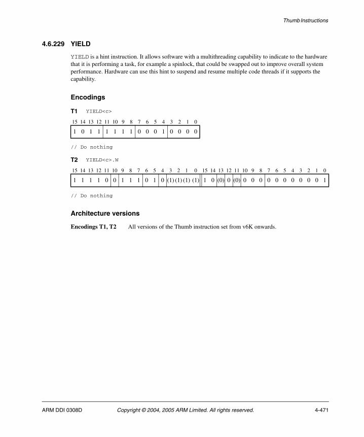
Thumb Instructions
4.6.229 YIELD
YIELD is a hint instruction. It allows software with a multithreading capability to indicate to the hardware that it is performing a task, for example a spinlock, that could be swapped out to improve overall system performance. Hardware can use this hint to suspend and resume multiple code threads if it supports the capability.
Encodings
// Do nothing
// Do nothing
Architecture versions
Encodings T1, T2 All versions of the Thumb instruction set from v6K onwards.
T1 YIELD<c>
15 14 13 12 11 10 9 8 7 6 5 4 3 2 1 0
1 0 1 1 1 1 1 1 0 0 0 1 0 0 0 0
T2 YIELD<c>.W
15 14 13 12 11 10 9 8 7 6 5 4 3 2 1 0 15 14 13 12 11 10 9 8 7 6 5 4 3 2 1 0
1 1 1 1 0 0 1 1 1 0 1 0 (1) (1) (1) (1) 1 0 (0) 0 (0) 0 0 0 0 0 0 0 0 0 0 1
ARM DDI 0308D Copyright © 2004, 2005 ARM Limited. All rights reserved. 4-471
Thumb Instructions
Assembler syntax
YIELD<c><q>
where:
<c><q> See Standard assembler syntax fields on page 4-6.
Operation
if ConditionPassed() then EncodingSpecificOperations(); Hint_Yield();
Exceptions
None.
4-472 Copyright © 2004, 2005 ARM Limited. All rights reserved. ARM DDI 0308D
Chapter 5 New ARM instructions
This chapter describes the new ARM® instructions introduced with Thumb®-2. It contains the following section:
• Alphabetical list of new ARM instructions on page 5-2.
ARM DDI 0308D Copyright © 2004, 2005 ARM Limited. All rights reserved. 5-1
New ARM instructions
5.1 Alphabetical list of new ARM instructions
Every new ARM instruction introduced with Thumb-2 is listed in this chapter. See Format of instruction descriptions on page 4-2 for details of the format used.
5-2 Copyright © 2004, 2005 ARM Limited. All rights reserved. ARM DDI 0308D
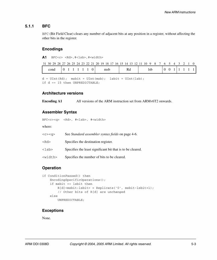
New ARM instructions
5.1.1 BFC
BFC (Bit Field Clear) clears any number of adjacent bits at any position in a register, without affecting the other bits in the register.
Encodings
d = UInt(Rd); msbit = UInt(msb); lsbit = UInt(lsb);if d == 15 then UNPREDICTABLE;
Architecture versions
Encoding A1 All versions of the ARM instruction set from ARMv6T2 onwards.
Assembler Syntax
BFC<c><q> <Rd>, #<lsb>, #<width>
where:
<c><q> See Standard assembler syntax fields on page 4-6.
<Rd> Specifies the destination register.
<lsb> Specifies the least significant bit that is to be cleared.
<width> Specifies the number of bits to be cleared.
Operation
if ConditionPassed() then EncodingSpecificOperations(); if msbit >= lsbit then R[d]<msbit:lsbit> = Replicate('0', msbit-lsbit+1); // Other bits of R[d] are unchanged else UNPREDICTABLE;
Exceptions
None.
A1 BFC<c> <Rd>,#<lsb>,#<width>
31 30 29 28 27 26 25 24 23 22 21 20 19 18 17 16 15 14 13 12 11 10 9 8 7 6 5 4 3 2 1 0
cond 0 1 1 1 1 1 0 msb Rd lsb 0 0 1 1 1 1 1
ARM DDI 0308D Copyright © 2004, 2005 ARM Limited. All rights reserved. 5-3
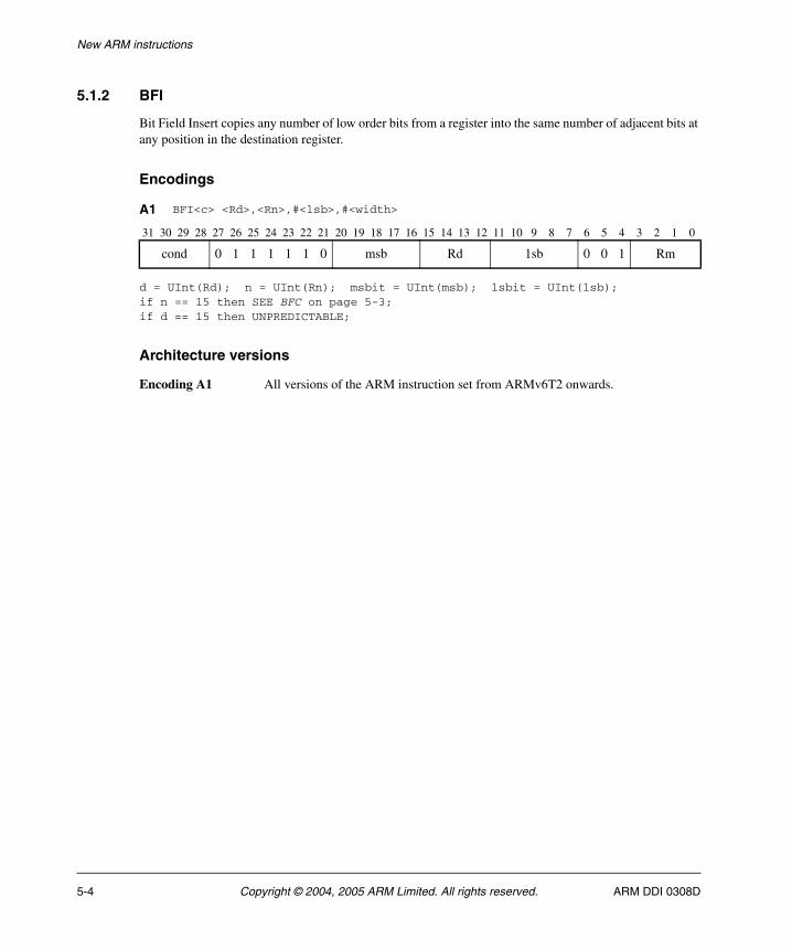
New ARM instructions
5.1.2 BFI
Bit Field Insert copies any number of low order bits from a register into the same number of adjacent bits at any position in the destination register.
Encodings
d = UInt(Rd); n = UInt(Rn); msbit = UInt(msb); lsbit = UInt(lsb);if n == 15 then SEE BFC on page 5-3;if d == 15 then UNPREDICTABLE;
Architecture versions
Encoding A1 All versions of the ARM instruction set from ARMv6T2 onwards.
A1 BFI<c> <Rd>,<Rn>,#<lsb>,#<width>
31 30 29 28 27 26 25 24 23 22 21 20 19 18 17 16 15 14 13 12 11 10 9 8 7 6 5 4 3 2 1 0
cond 0 1 1 1 1 1 0 msb Rd 1sb 0 0 1 Rm
5-4 Copyright © 2004, 2005 ARM Limited. All rights reserved. ARM DDI 0308D
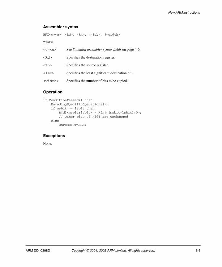
New ARM instructions
Assembler syntax
BFI<c><q> <Rd>, <Rn>, #<lsb>, #<width>
where:
<c><q> See Standard assembler syntax fields on page 4-6.
<Rd> Specifies the destination register.
<Rn> Specifies the source register.
<lsb> Specifies the least significant destination bit.
<width> Specifies the number of bits to be copied.
Operation
if ConditionPassed() then EncodingSpecificOperations(); if msbit >= lsbit then R[d]<msbit:lsbit> = R[n]<(msbit-lsbit):0>; // Other bits of R[d] are unchanged else UNPREDICTABLE;
Exceptions
None.
ARM DDI 0308D Copyright © 2004, 2005 ARM Limited. All rights reserved. 5-5
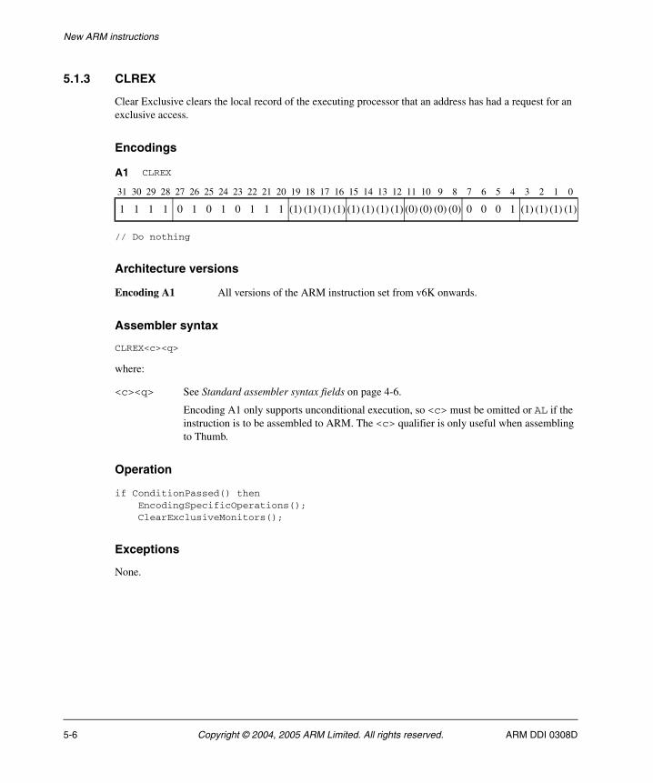
New ARM instructions
5.1.3 CLREX
Clear Exclusive clears the local record of the executing processor that an address has had a request for an exclusive access.
Encodings
// Do nothing
Architecture versions
Encoding A1 All versions of the ARM instruction set from v6K onwards.
Assembler syntax
CLREX<c><q>
where:
<c><q> See Standard assembler syntax fields on page 4-6.
Encoding A1 only supports unconditional execution, so <c> must be omitted or AL if the instruction is to be assembled to ARM. The <c> qualifier is only useful when assembling to Thumb.
Operation
if ConditionPassed() then EncodingSpecificOperations(); ClearExclusiveMonitors();
Exceptions
None.
A1 CLREX
31 30 29 28 27 26 25 24 23 22 21 20 19 18 17 16 15 14 13 12 11 10 9 8 7 6 5 4 3 2 1 0
1 1 1 1 0 1 0 1 0 1 1 1 (1) (1) (1) (1) (1) (1) (1) (1) (0) (0) (0) (0) 0 0 0 1 (1) (1) (1) (1)
5-6 Copyright © 2004, 2005 ARM Limited. All rights reserved. ARM DDI 0308D
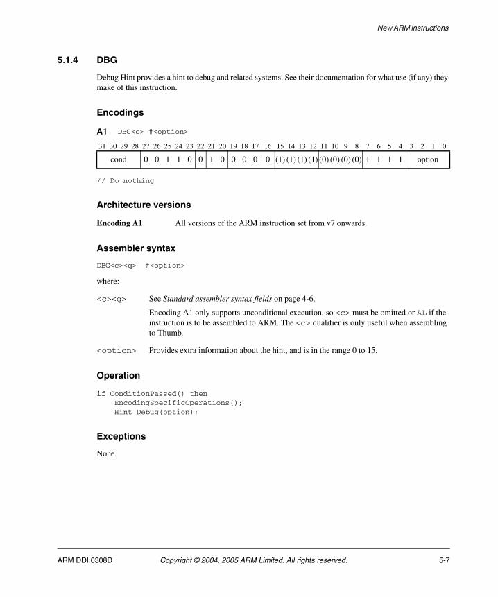
New ARM instructions
5.1.4 DBG
Debug Hint provides a hint to debug and related systems. See their documentation for what use (if any) they make of this instruction.
Encodings
// Do nothing
Architecture versions
Encoding A1 All versions of the ARM instruction set from v7 onwards.
Assembler syntax
DBG<c><q> #<option>
where:
<c><q> See Standard assembler syntax fields on page 4-6.
Encoding A1 only supports unconditional execution, so <c> must be omitted or AL if the instruction is to be assembled to ARM. The <c> qualifier is only useful when assembling to Thumb.
<option> Provides extra information about the hint, and is in the range 0 to 15.
Operation
if ConditionPassed() then EncodingSpecificOperations(); Hint_Debug(option);
Exceptions
None.
A1 DBG<c> #<option>
31 30 29 28 27 26 25 24 23 22 21 20 19 18 17 16 15 14 13 12 11 10 9 8 7 6 5 4 3 2 1 0
cond 0 0 1 1 0 0 1 0 0 0 0 0 (1) (1) (1) (1) (0) (0) (0) (0) 1 1 1 1 option
ARM DDI 0308D Copyright © 2004, 2005 ARM Limited. All rights reserved. 5-7
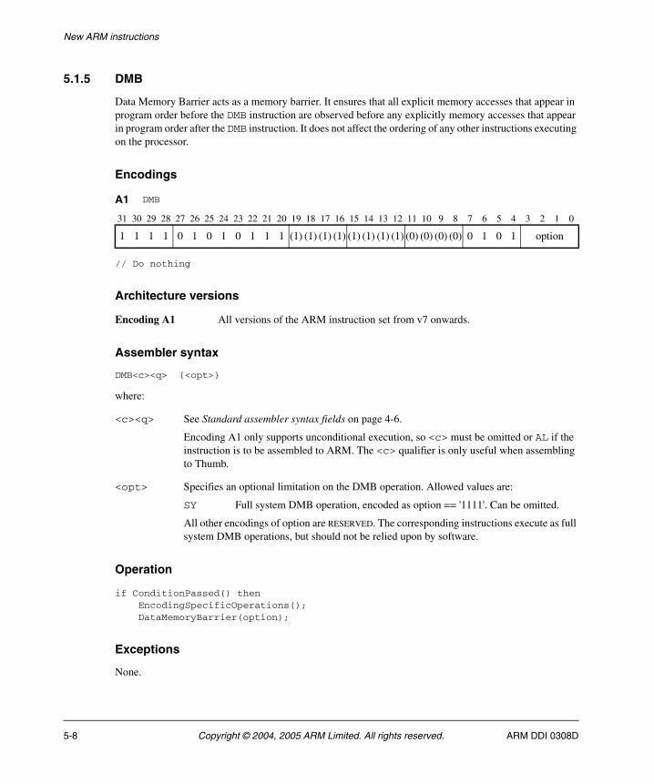
New ARM instructions
5.1.5 DMB
Data Memory Barrier acts as a memory barrier. It ensures that all explicit memory accesses that appear in program order before the DMB instruction are observed before any explicitly memory accesses that appear in program order after the DMB instruction. It does not affect the ordering of any other instructions executing on the processor.
Encodings
// Do nothing
Architecture versions
Encoding A1 All versions of the ARM instruction set from v7 onwards.
Assembler syntax
DMB<c><q> {<opt>}
where:
<c><q> See Standard assembler syntax fields on page 4-6.
Encoding A1 only supports unconditional execution, so <c> must be omitted or AL if the instruction is to be assembled to ARM. The <c> qualifier is only useful when assembling to Thumb.
<opt> Specifies an optional limitation on the DMB operation. Allowed values are:
SY Full system DMB operation, encoded as option == '1111'. Can be omitted.
All other encodings of option are RESERVED. The corresponding instructions execute as full system DMB operations, but should not be relied upon by software.
Operation
if ConditionPassed() then EncodingSpecificOperations(); DataMemoryBarrier(option);
Exceptions
None.
A1 DMB
31 30 29 28 27 26 25 24 23 22 21 20 19 18 17 16 15 14 13 12 11 10 9 8 7 6 5 4 3 2 1 0
1 1 1 1 0 1 0 1 0 1 1 1 (1) (1) (1) (1) (1) (1) (1) (1) (0) (0) (0) (0) 0 1 0 1 option
5-8 Copyright © 2004, 2005 ARM Limited. All rights reserved. ARM DDI 0308D
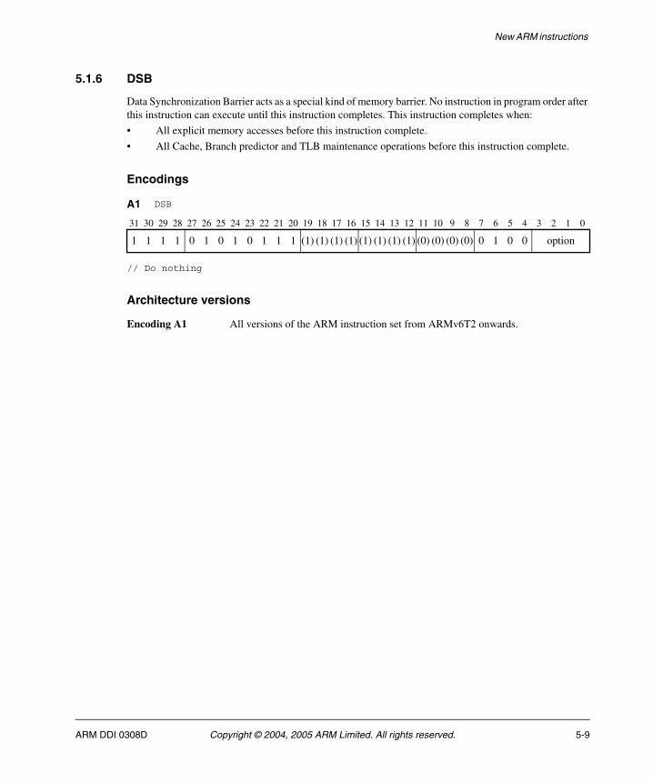
New ARM instructions
5.1.6 DSB
Data Synchronization Barrier acts as a special kind of memory barrier. No instruction in program order after this instruction can execute until this instruction completes. This instruction completes when:
• All explicit memory accesses before this instruction complete.
• All Cache, Branch predictor and TLB maintenance operations before this instruction complete.
Encodings
// Do nothing
Architecture versions
Encoding A1 All versions of the ARM instruction set from ARMv6T2 onwards.
A1 DSB
31 30 29 28 27 26 25 24 23 22 21 20 19 18 17 16 15 14 13 12 11 10 9 8 7 6 5 4 3 2 1 0
1 1 1 1 0 1 0 1 0 1 1 1 (1) (1) (1) (1) (1) (1) (1) (1) (0) (0) (0) (0) 0 1 0 0 option
ARM DDI 0308D Copyright © 2004, 2005 ARM Limited. All rights reserved. 5-9
New ARM instructions
Assembler syntax
DSB<c><q> {<opt>}
where:
<c><q> See Standard assembler syntax fields on page 4-6.
Encoding A1 only supports unconditional execution, so <c> must be omitted or AL if the instruction is to be assembled to ARM. The <c> qualifier is only useful when assembling to Thumb.
<opt> Specifies an optional limitation on the DSB operation. Allowed values are:
SY Full system DSB operation, encoded as option == '1111'. Can be omitted.
UN DSB operation only out to the point of unification, encoded as option == '0111'.
ST DSB operation that waits only for stores to complete, encoded as option == '1110'.
UNST DSB operation that waits only for stores to complete and only out to the point of unification, encoded as option == '0110'.
All other encodings of option are RESERVED. The corresponding instructions execute as full system DSB operations, but should not be relied upon by software.
Operation
if ConditionPassed() then EncodingSpecificOperations(); DataSynchronizationBarrier(option);
Exceptions
None.
5-10 Copyright © 2004, 2005 ARM Limited. All rights reserved. ARM DDI 0308D
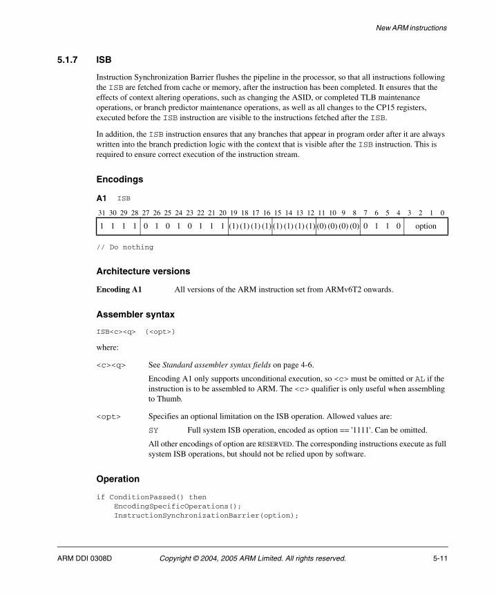
New ARM instructions
5.1.7 ISB
Instruction Synchronization Barrier flushes the pipeline in the processor, so that all instructions following the ISB are fetched from cache or memory, after the instruction has been completed. It ensures that the effects of context altering operations, such as changing the ASID, or completed TLB maintenance operations, or branch predictor maintenance operations, as well as all changes to the CP15 registers, executed before the ISB instruction are visible to the instructions fetched after the ISB.
In addition, the ISB instruction ensures that any branches that appear in program order after it are always written into the branch prediction logic with the context that is visible after the ISB instruction. This is required to ensure correct execution of the instruction stream.
Encodings
// Do nothing
Architecture versions
Encoding A1 All versions of the ARM instruction set from ARMv6T2 onwards.
Assembler syntax
ISB<c><q> {<opt>}
where:
<c><q> See Standard assembler syntax fields on page 4-6.
Encoding A1 only supports unconditional execution, so <c> must be omitted or AL if the instruction is to be assembled to ARM. The <c> qualifier is only useful when assembling to Thumb.
<opt> Specifies an optional limitation on the ISB operation. Allowed values are:
SY Full system ISB operation, encoded as option == '1111'. Can be omitted.
All other encodings of option are RESERVED. The corresponding instructions execute as full system ISB operations, but should not be relied upon by software.
Operation
if ConditionPassed() then EncodingSpecificOperations(); InstructionSynchronizationBarrier(option);
A1 ISB
31 30 29 28 27 26 25 24 23 22 21 20 19 18 17 16 15 14 13 12 11 10 9 8 7 6 5 4 3 2 1 0
1 1 1 1 0 1 0 1 0 1 1 1 (1) (1) (1) (1) (1) (1) (1) (1) (0) (0) (0) (0) 0 1 1 0 option
ARM DDI 0308D Copyright © 2004, 2005 ARM Limited. All rights reserved. 5-11
New ARM instructions
Exceptions
None.
5-12 Copyright © 2004, 2005 ARM Limited. All rights reserved. ARM DDI 0308D
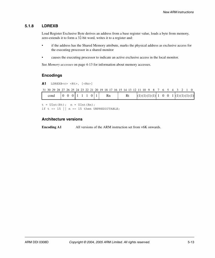
New ARM instructions
5.1.8 LDREXB
Load Register Exclusive Byte derives an address from a base register value, loads a byte from memory, zero-extends it to form a 32-bit word, writes it to a register and:
• if the address has the Shared Memory attribute, marks the physical address as exclusive access for the executing processor in a shared monitor
• causes the executing processor to indicate an active exclusive access in the local monitor.
See Memory accesses on page 4-13 for information about memory accesses.
Encodings
t = UInt(Rt); n = UInt(Rn);if t == 15 || n == 15 then UNPREDICTABLE;
Architecture versions
Encoding A1 All versions of the ARM instruction set from v6K onwards.
A1 LDREXB<c> <Rt>, [<Rn>]
31 30 29 28 27 26 25 24 23 22 21 20 19 18 17 16 15 14 13 12 11 10 9 8 7 6 5 4 3 2 1 0
cond 0 0 0 1 1 1 0 1 Rn Rt (1) (1) (1) (1) 1 0 0 1 (1) (1) (1) (1)
ARM DDI 0308D Copyright © 2004, 2005 ARM Limited. All rights reserved. 5-13

New ARM instructions
Assembler syntax
LDREXB<c><q> <Rt>, [<Rn>]
where:
<c><q> See Standard assembler syntax fields on page 4-6.
<Rt> Specifies the destination register.
<Rn> Specifies the base register.
Operation
if ConditionPassed() then EncodingSpecificOperations(); address = R[n]; SetExclusiveMonitors(address,1); R[t] = MemAA[address,1];
Exceptions
Data Abort.
5-14 Copyright © 2004, 2005 ARM Limited. All rights reserved. ARM DDI 0308D
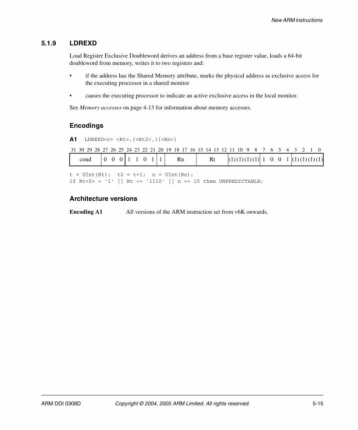
New ARM instructions
5.1.9 LDREXD
Load Register Exclusive Doubleword derives an address from a base register value, loads a 64-bit doubleword from memory, writes it to two registers and:
• if the address has the Shared Memory attribute, marks the physical address as exclusive access for the executing processor in a shared monitor
• causes the executing processor to indicate an active exclusive access in the local monitor.
See Memory accesses on page 4-13 for information about memory accesses.
Encodings
t = UInt(Rt); t2 = t+1; n = UInt(Rn);if Rt<0> = '1' || Rt == '1110' || n == 15 then UNPREDICTABLE;
Architecture versions
Encoding A1 All versions of the ARM instruction set from v6K onwards.
A1 LDREXD<c> <Rt>,{<Rt2>,}[<Rn>]
31 30 29 28 27 26 25 24 23 22 21 20 19 18 17 16 15 14 13 12 11 10 9 8 7 6 5 4 3 2 1 0
cond 0 0 0 1 1 0 1 1 Rn Rt (1) (1) (1) (1) 1 0 0 1 (1) (1) (1) (1)
ARM DDI 0308D Copyright © 2004, 2005 ARM Limited. All rights reserved. 5-15
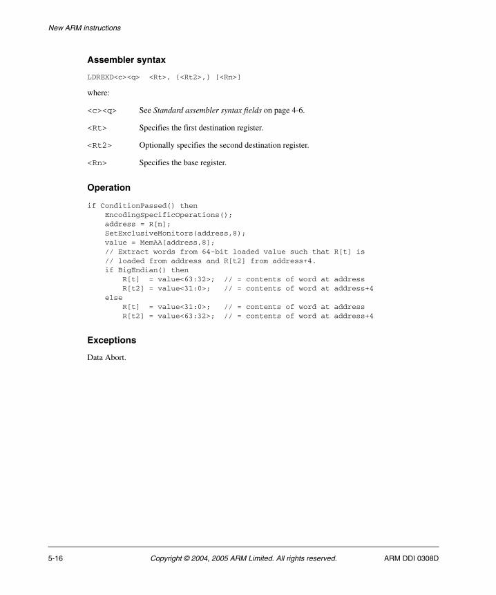
New ARM instructions
Assembler syntax
LDREXD<c><q> <Rt>, {<Rt2>,} [<Rn>]
where:
<c><q> See Standard assembler syntax fields on page 4-6.
<Rt> Specifies the first destination register.
<Rt2> Optionally specifies the second destination register.
<Rn> Specifies the base register.
Operation
if ConditionPassed() then EncodingSpecificOperations(); address = R[n]; SetExclusiveMonitors(address,8); value = MemAA[address,8]; // Extract words from 64-bit loaded value such that R[t] is // loaded from address and R[t2] from address+4. if BigEndian() then R[t] = value<63:32>; // = contents of word at address R[t2] = value<31:0>; // = contents of word at address+4 else R[t] = value<31:0>; // = contents of word at address R[t2] = value<63:32>; // = contents of word at address+4
Exceptions
Data Abort.
5-16 Copyright © 2004, 2005 ARM Limited. All rights reserved. ARM DDI 0308D

New ARM instructions
5.1.10 LDREXH
Load Register Exclusive Halfword derives an address from a base register value, loads a halfword from memory, zero-extends it to form a 32-bit word, writes it to a register and:
• if the address has the Shared Memory attribute, marks the physical address as exclusive access for the executing processor in a shared monitor
• causes the executing processor to indicate an active exclusive access in the local monitor.
See Memory accesses on page 4-13 for information about memory accesses.
Encodings
t = UInt(Rt); n = UInt(Rn);if t == 15 || n == 15 then UNPREDICTABLE;
Architecture versions
Encoding A1 All versions of the ARM instruction set from v6K onwards.
A1 LDREXH<c> <Rt>, [<Rn>]
31 30 29 28 27 26 25 24 23 22 21 20 19 18 17 16 15 14 13 12 11 10 9 8 7 6 5 4 3 2 1 0
cond 0 0 0 1 1 1 1 1 Rn Rt (1) (1) (1) (1) 1 0 0 1 (1) (1) (1) (1)
ARM DDI 0308D Copyright © 2004, 2005 ARM Limited. All rights reserved. 5-17
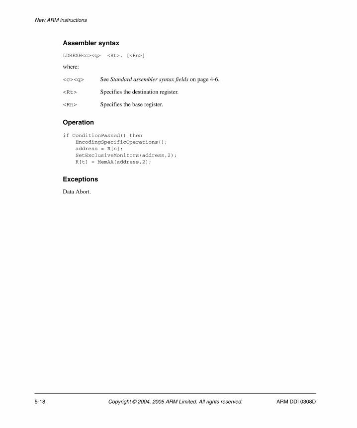
New ARM instructions
Assembler syntax
LDREXH<c><q> <Rt>, [<Rn>]
where:
<c><q> See Standard assembler syntax fields on page 4-6.
<Rt> Specifies the destination register.
<Rn> Specifies the base register.
Operation
if ConditionPassed() then EncodingSpecificOperations(); address = R[n]; SetExclusiveMonitors(address,2); R[t] = MemAA[address,2];
Exceptions
Data Abort.
5-18 Copyright © 2004, 2005 ARM Limited. All rights reserved. ARM DDI 0308D

New ARM instructions
5.1.11 LDRHT
Load Register Halfword Unprivileged calculates an address from a base register value and an immediate offset, loads a halfword from memory, zero-extends it to form a 32-bit word, and writes it to a register. See Memory accesses on page 4-13 for information about memory accesses.
The memory access is restricted as if the processor were running in User mode. (This makes no difference if the processor is actually running in User mode.)
Encodings
t == UInt(Rt); n = UInt(Rn); postindex = TRUE; add = (U == '1');offset = ZeroExtend(imm4H:imm4L, 32);if t == 15 || n == 15 || n == t then UNPREDICTABLE;
t = UInt(Rt); n = UInt(Rn); m = UInt(Rm);postindex = TRUE; add = (U == '1');offset = R[m];if t == 15 || n == 15 || n == t || m == 15 then UNPREDICTABLE;
Architecture versions
Encodings A1, A2 All versions of the ARM instruction set from ARMv6T2 onwards.
A1 LDRHT<c> <Rt>, [<Rn>] {, #+/-<offset_8>}
31 30 29 28 27 26 25 24 23 22 21 20 19 18 17 16 15 14 13 12 11 10 9 8 7 6 5 4 3 2 1 0
cond 0 0 0 0 U 1 1 1 Rn Rt imm4H 1 0 1 1 imm4L
A2 LDRHT<c> <Rt>, [<Rn>], #+/-<Rm>
31 30 29 28 27 26 25 24 23 22 21 20 19 18 17 16 15 14 13 12 11 10 9 8 7 6 5 4 3 2 1 0
cond 0 0 0 0 U 0 1 1 Rn Rt (0) (0) (0) (0) 1 0 1 1 Rm
ARM DDI 0308D Copyright © 2004, 2005 ARM Limited. All rights reserved. 5-19

New ARM instructions
Assembler syntax
LDRHT<c><q> <Rt>, [<Rn>] {, #<imm>}LDRHT<c><q> <Rt>, [<Rn>], +/-<Rm>
where:
<c><q> See Standard assembler syntax fields on page 4-6.
<Rt> Specifies the destination register.
<Rn> Specifies the base register.
<imm> Specifies the immediate offset added to the value of <Rn> to form the address. <imm> can be omitted, meaning an offset of 0.
<Rm> Specifies the register containing the offset.
Operation
if ConditionPassed() then EncodingSpecificOperations(); offset_addr = if add then (R[n] + offset) else (R[n] - offset); address = if postindex then R[n] else offset_addr; if postindex then R[n] = offset_addr; R[t] = ZeroExtend(MemU_unpriv[address,2], 32);
Exceptions
Data Abort.
5-20 Copyright © 2004, 2005 ARM Limited. All rights reserved. ARM DDI 0308D
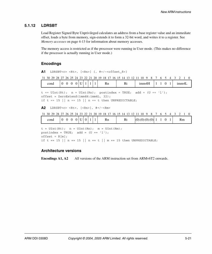
New ARM instructions
5.1.12 LDRSBT
Load Register Signed Byte Unprivileged calculates an address from a base register value and an immediate offset, loads a byte from memory, sign-extends it to form a 32-bit word, and writes it to a register. See Memory accesses on page 4-13 for information about memory accesses.
The memory access is restricted as if the processor were running in User mode. (This makes no difference if the processor is actually running in User mode.)
Encodings
t == UInt(Rt); n = UInt(Rn); postindex = TRUE; add = (U == '1');offset = ZeroExtend(imm4H:imm4L, 32);if t == 15 || n == 15 || n == t then UNPREDICTABLE;
t = UInt(Rt); n = UInt(Rn); m = UInt(Rm);postindex = TRUE; add = (U == '1');offset = R[m];if t == 15 || n == 15 || n == t || m == 15 then UNPREDICTABLE;
Architecture versions
Encodings A1, A2 All versions of the ARM instruction set from ARMv6T2 onwards.
A1 LDRSBT<c> <Rt>, [<Rn>] {, #+/-<offset_8>}
31 30 29 28 27 26 25 24 23 22 21 20 19 18 17 16 15 14 13 12 11 10 9 8 7 6 5 4 3 2 1 0
cond 0 0 0 0 U 1 1 1 Rn Rt imm4H 1 1 0 1 imm4L
A2 LDRSBT<c> <Rt>, [<Rn>], #+/-<Rm>
31 30 29 28 27 26 25 24 23 22 21 20 19 18 17 16 15 14 13 12 11 10 9 8 7 6 5 4 3 2 1 0
cond 0 0 0 0 U 0 1 1 Rn Rt (0) (0) (0) (0) 1 1 0 1 Rm
ARM DDI 0308D Copyright © 2004, 2005 ARM Limited. All rights reserved. 5-21
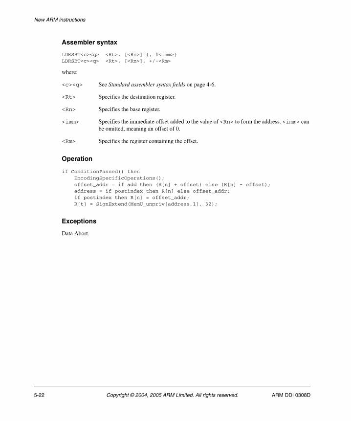
New ARM instructions
Assembler syntax
LDRSBT<c><q> <Rt>, [<Rn>] {, #<imm>}LDRSBT<c><q> <Rt>, [<Rn>], +/-<Rm>
where:
<c><q> See Standard assembler syntax fields on page 4-6.
<Rt> Specifies the destination register.
<Rn> Specifies the base register.
<imm> Specifies the immediate offset added to the value of <Rn> to form the address. <imm> can be omitted, meaning an offset of 0.
<Rm> Specifies the register containing the offset.
Operation
if ConditionPassed() then EncodingSpecificOperations(); offset_addr = if add then (R[n] + offset) else (R[n] - offset); address = if postindex then R[n] else offset_addr; if postindex then R[n] = offset_addr; R[t] = SignExtend(MemU_unpriv[address,1], 32);
Exceptions
Data Abort.
5-22 Copyright © 2004, 2005 ARM Limited. All rights reserved. ARM DDI 0308D

New ARM instructions
5.1.13 LDRSHT
Load Register Signed Halfword Unprivileged calculates an address from a base register value and an immediate offset, loads a halfword from memory, sign-extends it to form a 32-bit word, and writes it to a register. See Memory accesses on page 4-13 for information about memory accesses.
The memory access is restricted as if the processor were running in User mode. (This makes no difference if the processor is actually running in User mode.)
Encodings
t == UInt(Rt); n = UInt(Rn); postindex = TRUE; add = (U == '1');offset = ZeroExtend(imm4H:imm4L, 32);if t == 15 || n == 15 || n == t then UNPREDICTABLE;
t = UInt(Rt); n = UInt(Rn); m = UInt(Rm);postindex = TRUE; add = (U == '1');offset = R[m];if t == 15 || n == 15 || n == t || m == 15 then UNPREDICTABLE;
Architecture versions
Encodings A1, A2 All versions of the ARM instruction set from ARMv6T2 onwards.
A1 LDRHT<c> <Rt>, [<Rn>] {, #+/-<offset_8>}
31 30 29 28 27 26 25 24 23 22 21 20 19 18 17 16 15 14 13 12 11 10 9 8 7 6 5 4 3 2 1 0
cond 0 0 0 0 U 1 1 1 Rn Rt imm4H 1 1 1 1 imm4L
A2 LDRHT<c> <Rt>, [<Rn>], #+/-<Rm>
31 30 29 28 27 26 25 24 23 22 21 20 19 18 17 16 15 14 13 12 11 10 9 8 7 6 5 4 3 2 1 0
cond 0 0 0 0 U 0 1 1 Rn Rt (0) (0) (0) (0) 1 1 1 1 Rm
ARM DDI 0308D Copyright © 2004, 2005 ARM Limited. All rights reserved. 5-23

New ARM instructions
Assembler syntax
LDRSHT<c><q> <Rt>, [<Rn>] {, #<imm>}LDRSHT<c><q> <Rt>, [<Rn>], +/-<Rm>
where:
<c><q> See Standard assembler syntax fields on page 4-6.
<Rt> Specifies the destination register.
<Rn> Specifies the base register.
<imm> Specifies the immediate offset added to the value of <Rn> to form the address. <imm> can be omitted, meaning an offset of 0.
<Rm> Specifies the register containing the offset.
Operation
if ConditionPassed() then EncodingSpecificOperations(); offset_addr = if add then (R[n] + offset) else (R[n] - offset); address = if postindex then R[n] else offset_addr; if postindex then R[n] = offset_addr; R[t] = SignExtend(MemU_unpriv[address,2], 32);
Exceptions
Data Abort.
5-24 Copyright © 2004, 2005 ARM Limited. All rights reserved. ARM DDI 0308D
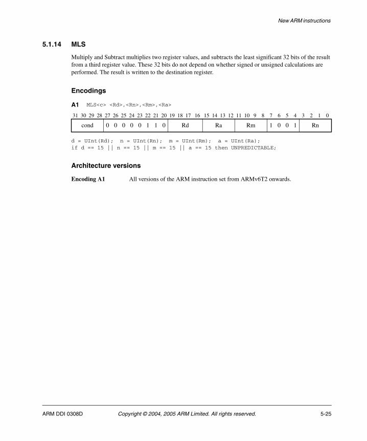
New ARM instructions
5.1.14 MLS
Multiply and Subtract multiplies two register values, and subtracts the least significant 32 bits of the result from a third register value. These 32 bits do not depend on whether signed or unsigned calculations are performed. The result is written to the destination register.
Encodings
d = UInt(Rd); n = UInt(Rn); m = UInt(Rm); a = UInt(Ra);if d == 15 || n == 15 || m == 15 || a == 15 then UNPREDICTABLE;
Architecture versions
Encoding A1 All versions of the ARM instruction set from ARMv6T2 onwards.
A1 MLS<c> <Rd>,<Rn>,<Rm>,<Ra>
31 30 29 28 27 26 25 24 23 22 21 20 19 18 17 16 15 14 13 12 11 10 9 8 7 6 5 4 3 2 1 0
cond 0 0 0 0 0 1 1 0 Rd Ra Rm 1 0 0 1 Rn
ARM DDI 0308D Copyright © 2004, 2005 ARM Limited. All rights reserved. 5-25
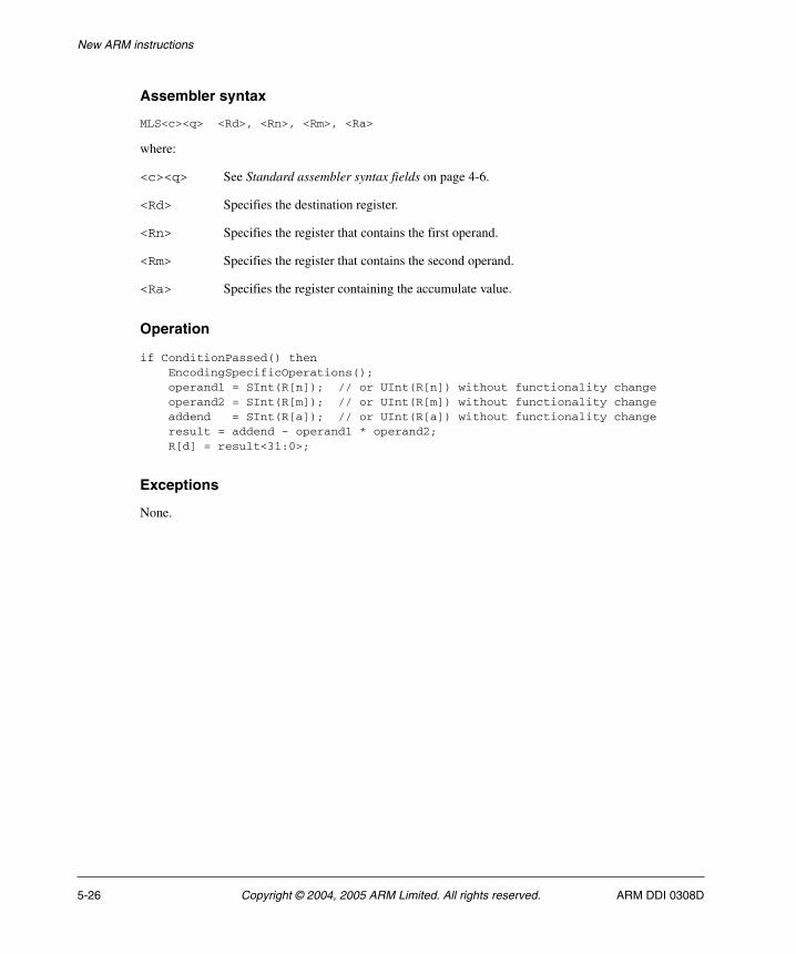
New ARM instructions
Assembler syntax
MLS<c><q> <Rd>, <Rn>, <Rm>, <Ra>
where:
<c><q> See Standard assembler syntax fields on page 4-6.
<Rd> Specifies the destination register.
<Rn> Specifies the register that contains the first operand.
<Rm> Specifies the register that contains the second operand.
<Ra> Specifies the register containing the accumulate value.
Operation
if ConditionPassed() then EncodingSpecificOperations(); operand1 = SInt(R[n]); // or UInt(R[n]) without functionality change operand2 = SInt(R[m]); // or UInt(R[m]) without functionality change addend = SInt(R[a]); // or UInt(R[a]) without functionality change result = addend - operand1 * operand2; R[d] = result<31:0>;
Exceptions
None.
5-26 Copyright © 2004, 2005 ARM Limited. All rights reserved. ARM DDI 0308D
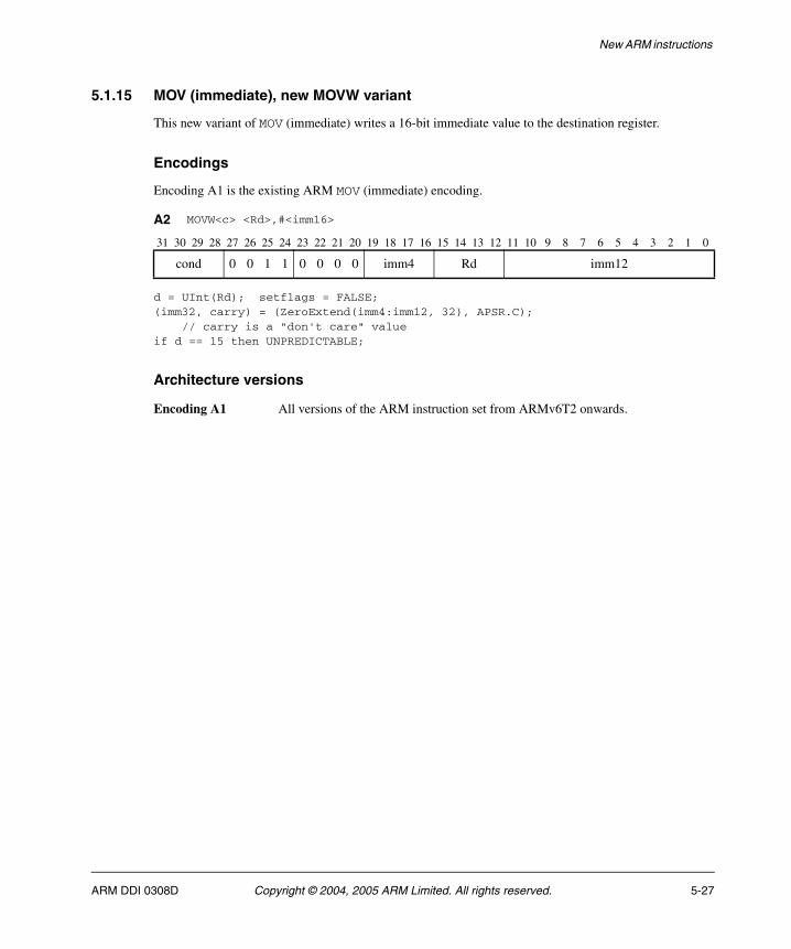
New ARM instructions
5.1.15 MOV (immediate), new MOVW variant
This new variant of MOV (immediate) writes a 16-bit immediate value to the destination register.
Encodings
Encoding A1 is the existing ARM MOV (immediate) encoding.
d = UInt(Rd); setflags = FALSE;(imm32, carry) = (ZeroExtend(imm4:imm12, 32), APSR.C); // carry is a "don't care" valueif d == 15 then UNPREDICTABLE;
Architecture versions
Encoding A1 All versions of the ARM instruction set from ARMv6T2 onwards.
A2 MOVW<c> <Rd>,#<imm16>
31 30 29 28 27 26 25 24 23 22 21 20 19 18 17 16 15 14 13 12 11 10 9 8 7 6 5 4 3 2 1 0
cond 0 0 1 1 0 0 0 0 imm4 Rd imm12
ARM DDI 0308D Copyright © 2004, 2005 ARM Limited. All rights reserved. 5-27
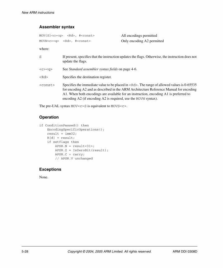
New ARM instructions
Assembler syntax
where:
S If present, specifies that the instruction updates the flags. Otherwise, the instruction does not update the flags.
<c><q> See Standard assembler syntax fields on page 4-6.
<Rd> Specifies the destination register.
<const> Specifies the immediate value to be placed in <Rd>. The range of allowed values is 0-65535 for encoding A2 and as described in the ARM Architecture Reference Manual for encoding A1. When both encodings are available for an instruction, encoding A1 is preferred to encoding A2 (if encoding A2 is required, use the MOVW syntax).
The pre-UAL syntax MOV<c>S is equivalent to MOVS<c>.
Operation
if ConditionPassed() then EncodingSpecificOperations(); result = imm32; R[d] = result; if setflags then APSR.N = result<31>; APSR.Z = IsZeroBit(result); APSR.C = carry; // APSR.V unchanged
Exceptions
None.
MOV{S}<c><q> <Rd>, #<const> All encodings permittedMOVW<c><q> <Rd>, #<const> Only encoding A2 permitted
5-28 Copyright © 2004, 2005 ARM Limited. All rights reserved. ARM DDI 0308D
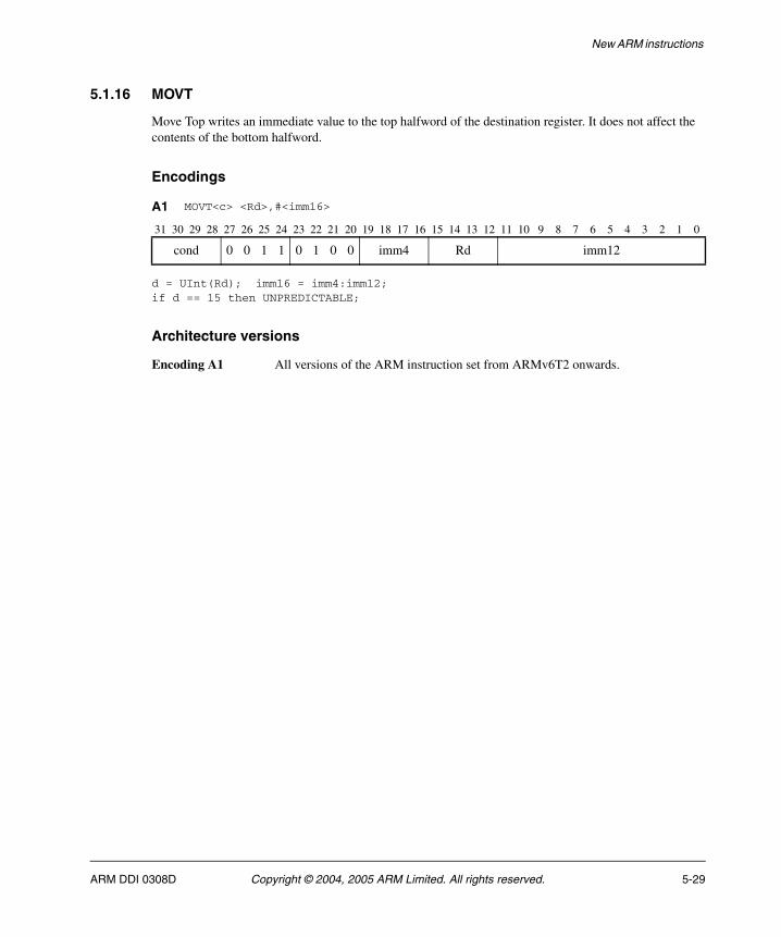
New ARM instructions
5.1.16 MOVT
Move Top writes an immediate value to the top halfword of the destination register. It does not affect the contents of the bottom halfword.
Encodings
d = UInt(Rd); imm16 = imm4:imm12;if d == 15 then UNPREDICTABLE;
Architecture versions
Encoding A1 All versions of the ARM instruction set from ARMv6T2 onwards.
A1 MOVT<c> <Rd>,#<imm16>
31 30 29 28 27 26 25 24 23 22 21 20 19 18 17 16 15 14 13 12 11 10 9 8 7 6 5 4 3 2 1 0
cond 0 0 1 1 0 1 0 0 imm4 Rd imm12
ARM DDI 0308D Copyright © 2004, 2005 ARM Limited. All rights reserved. 5-29
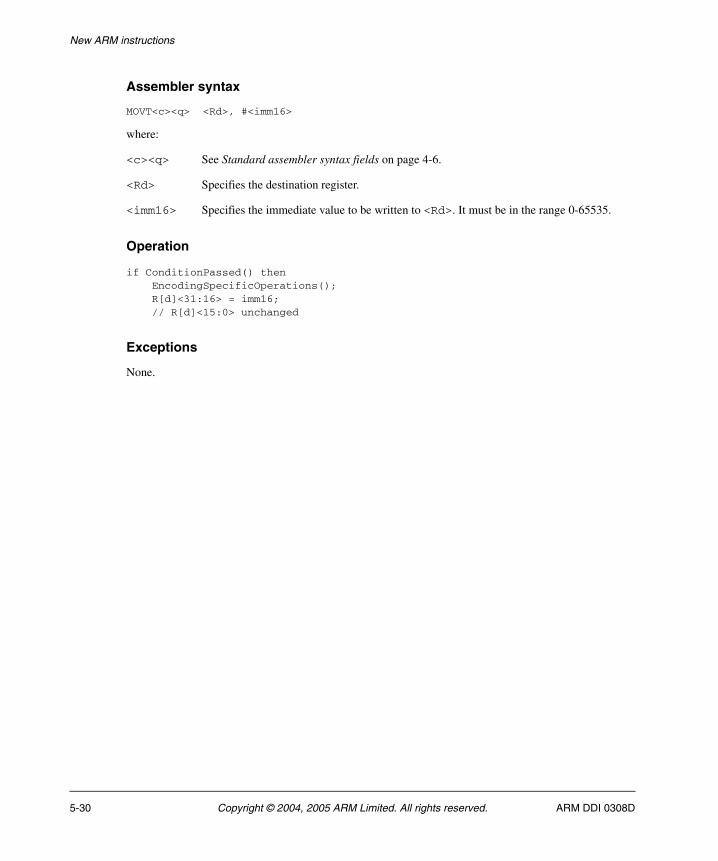
New ARM instructions
Assembler syntax
MOVT<c><q> <Rd>, #<imm16>
where:
<c><q> See Standard assembler syntax fields on page 4-6.
<Rd> Specifies the destination register.
<imm16> Specifies the immediate value to be written to <Rd>. It must be in the range 0-65535.
Operation
if ConditionPassed() then EncodingSpecificOperations(); R[d]<31:16> = imm16; // R[d]<15:0> unchanged
Exceptions
None.
5-30 Copyright © 2004, 2005 ARM Limited. All rights reserved. ARM DDI 0308D
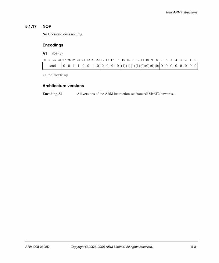
New ARM instructions
5.1.17 NOP
No Operation does nothing.
Encodings
// Do nothing
Architecture versions
Encoding A1 All versions of the ARM instruction set from ARMv6T2 onwards.
A1 NOP<c>
31 30 29 28 27 26 25 24 23 22 21 20 19 18 17 16 15 14 13 12 11 10 9 8 7 6 5 4 3 2 1 0
cond 0 0 1 1 0 0 1 0 0 0 0 0 (1) (1) (1) (1) (0) (0) (0) (0) 0 0 0 0 0 0 0 0
ARM DDI 0308D Copyright © 2004, 2005 ARM Limited. All rights reserved. 5-31
New ARM instructions
Assembler syntax
NOP<c><q>
where:
<c><q> See Standard assembler syntax fields on page 4-6.
Operation
if ConditionPassed() then EncodingSpecificOperations(); // Do nothing
Exceptions
None.
5-32 Copyright © 2004, 2005 ARM Limited. All rights reserved. ARM DDI 0308D
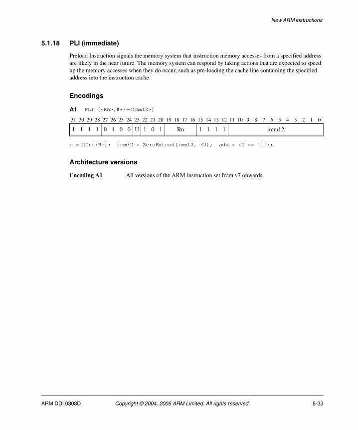
New ARM instructions
5.1.18 PLI (immediate)
Preload Instruction signals the memory system that instruction memory accesses from a specified address are likely in the near future. The memory system can respond by taking actions that are expected to speed up the memory accesses when they do occur, such as pre-loading the cache line containing the specified address into the instruction cache.
Encodings
n = UInt(Rn); imm32 = ZeroExtend(imm12, 32); add = (U == '1');
Architecture versions
Encoding A1 All versions of the ARM instruction set from v7 onwards.
A1 PLI [<Rn>,#+/-<imm12>]
31 30 29 28 27 26 25 24 23 22 21 20 19 18 17 16 15 14 13 12 11 10 9 8 7 6 5 4 3 2 1 0
1 1 1 1 0 1 0 0 U 1 0 1 Rn 1 1 1 1 imm12
ARM DDI 0308D Copyright © 2004, 2005 ARM Limited. All rights reserved. 5-33
New ARM instructions
Assembler syntax
PLI<c><q> [<Rn>, #+/-<imm12>]
where:
<c><q> See Standard assembler syntax fields on page 4-6.
Encoding A1 only supports unconditional execution, so <c> must be omitted or AL if the instruction is to be assembled to ARM. The <c> qualifier is only useful when assembling to Thumb.
<Rn> Is the base register.
<imm12> Specifies the offset from the base register.
Operation
if ConditionPassed() then EncodingSpecificOperations(); base = if n == 15 then Align(PC,4) else R[n]; address = if add then (base + imm32) else (base - imm32); Hint_PreloadInstr(address);
Exceptions
None.
5-34 Copyright © 2004, 2005 ARM Limited. All rights reserved. ARM DDI 0308D
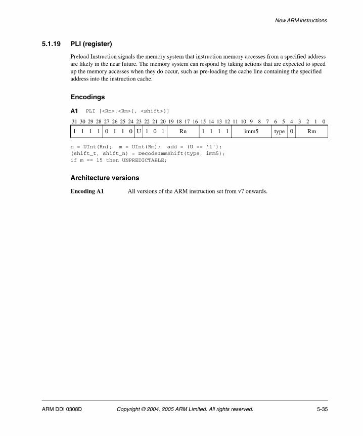
New ARM instructions
5.1.19 PLI (register)
Preload Instruction signals the memory system that instruction memory accesses from a specified address are likely in the near future. The memory system can respond by taking actions that are expected to speed up the memory accesses when they do occur, such as pre-loading the cache line containing the specified address into the instruction cache.
Encodings
n = UInt(Rn); m = UInt(Rm); add = (U == '1');(shift_t, shift_n) = DecodeImmShift(type, imm5);if m == 15 then UNPREDICTABLE;
Architecture versions
Encoding A1 All versions of the ARM instruction set from v7 onwards.
A1 PLI [<Rn>,<Rm>{, <shift>}]
31 30 29 28 27 26 25 24 23 22 21 20 19 18 17 16 15 14 13 12 11 10 9 8 7 6 5 4 3 2 1 0
1 1 1 1 0 1 1 0 U 1 0 1 Rn 1 1 1 1 imm5 type 0 Rm
ARM DDI 0308D Copyright © 2004, 2005 ARM Limited. All rights reserved. 5-35
New ARM instructions
Assembler syntax
PLI<c><q> [<Rn>, <Rm> {, <shift>}]
where:
<c><q> See Standard assembler syntax fields on page 4-6.
Encoding A1 only supports unconditional execution, so <c> must be omitted or AL if the instruction is to be assembled to ARM. The <c> qualifier is only useful when assembling to Thumb.
<Rn> Is the base register.
<Rm> Is the optionally shifted offset register.
<shift> Specifies the shift to apply to the value read from <Rm>. See Constant shifts applied to a register on page 4-10 for details.
Operation
if ConditionPassed() then EncodingSpecificOperations(); offset = Shift(R[m], shift_t, shift_n, APSR.C); address = if add then (R[n] + offset) else (R[n] - offset); Hint_PreloadInstr(address);
Exceptions
None.
5-36 Copyright © 2004, 2005 ARM Limited. All rights reserved. ARM DDI 0308D
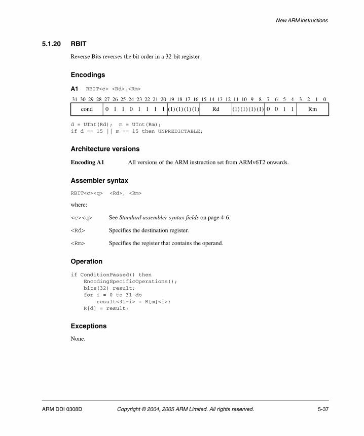
New ARM instructions
5.1.20 RBIT
Reverse Bits reverses the bit order in a 32-bit register.
Encodings
d = UInt(Rd); m = UInt(Rm);if d == 15 || m == 15 then UNPREDICTABLE;
Architecture versions
Encoding A1 All versions of the ARM instruction set from ARMv6T2 onwards.
Assembler syntax
RBIT<c><q> <Rd>, <Rm>
where:
<c><q> See Standard assembler syntax fields on page 4-6.
<Rd> Specifies the destination register.
<Rm> Specifies the register that contains the operand.
Operation
if ConditionPassed() then EncodingSpecificOperations(); bits(32) result; for i = 0 to 31 do result<31-i> = R[m]<i>; R[d] = result;
Exceptions
None.
A1 RBIT<c> <Rd>,<Rm>
31 30 29 28 27 26 25 24 23 22 21 20 19 18 17 16 15 14 13 12 11 10 9 8 7 6 5 4 3 2 1 0
cond 0 1 1 0 1 1 1 1 (1) (1) (1) (1) Rd (1) (1) (1) (1) 0 0 1 1 Rm
ARM DDI 0308D Copyright © 2004, 2005 ARM Limited. All rights reserved. 5-37
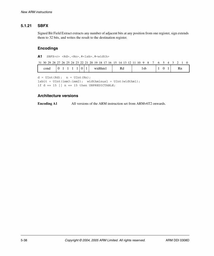
New ARM instructions
5.1.21 SBFX
Signed Bit Field Extract extracts any number of adjacent bits at any position from one register, sign extends them to 32 bits, and writes the result to the destination register.
Encodings
d = UInt(Rd); n = UInt(Rn);lsbit = UInt(imm3:imm2); widthminus1 = UInt(widthm1);if d == 15 || n == 15 then UNPREDICTABLE;
Architecture versions
Encoding A1 All versions of the ARM instruction set from ARMv6T2 onwards.
A1 SBFX<c> <Rd>,<Rn>,#<lsb>,#<width>
31 30 29 28 27 26 25 24 23 22 21 20 19 18 17 16 15 14 13 12 11 10 9 8 7 6 5 4 3 2 1 0
cond 0 1 1 1 1 0 1 widthm1 Rd 1sb 1 0 1 Rn
5-38 Copyright © 2004, 2005 ARM Limited. All rights reserved. ARM DDI 0308D
New ARM instructions
Assembler syntax
SBFX<c><q> <Rd>, <Rn>, #<lsb>, #<width>
where:
<c><q> See Standard assembler syntax fields on page 4-6.
<Rd> Specifies the destination register.
<Rn> Specifies the register that contains the first operand.
<lsb> is the bit number of the least significant bit in the bitfield (in the range 0-31).
<width> is the width of the bitfield (in the range 1-32).
Operation
if ConditionPassed() then EncodingSpecificOperations(); msbit = lsbit + widthminus1; if msbit <= 31 then R[d] = SignExtend(R[n]<msbit:lsbit>, 32); else UNPREDICTABLE;
Exceptions
None.
ARM DDI 0308D Copyright © 2004, 2005 ARM Limited. All rights reserved. 5-39
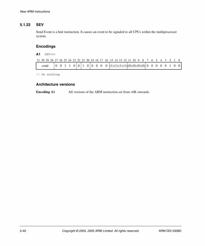
New ARM instructions
5.1.22 SEV
Send Event is a hint instruction. It causes an event to be signaled to all CPUs within the multiprocessor system.
Encodings
// Do nothing
Architecture versions
Encoding A1 All versions of the ARM instruction set from v6K onwards.
A1 SEV<c>
31 30 29 28 27 26 25 24 23 22 21 20 19 18 17 16 15 14 13 12 11 10 9 8 7 6 5 4 3 2 1 0
cond 0 0 1 1 0 0 1 0 0 0 0 0 (1) (1) (1) (1) (0) (0) (0) (0) 0 0 0 0 0 1 0 0
5-40 Copyright © 2004, 2005 ARM Limited. All rights reserved. ARM DDI 0308D

New ARM instructions
Assembler syntax
SEV<c><q>
where:
<c><q> See Standard assembler syntax fields on page 4-6.
Operation
if ConditionPassed() then EncodingSpecificOperations(); Hint_SendEvent();
Exceptions
None.
ARM DDI 0308D Copyright © 2004, 2005 ARM Limited. All rights reserved. 5-41
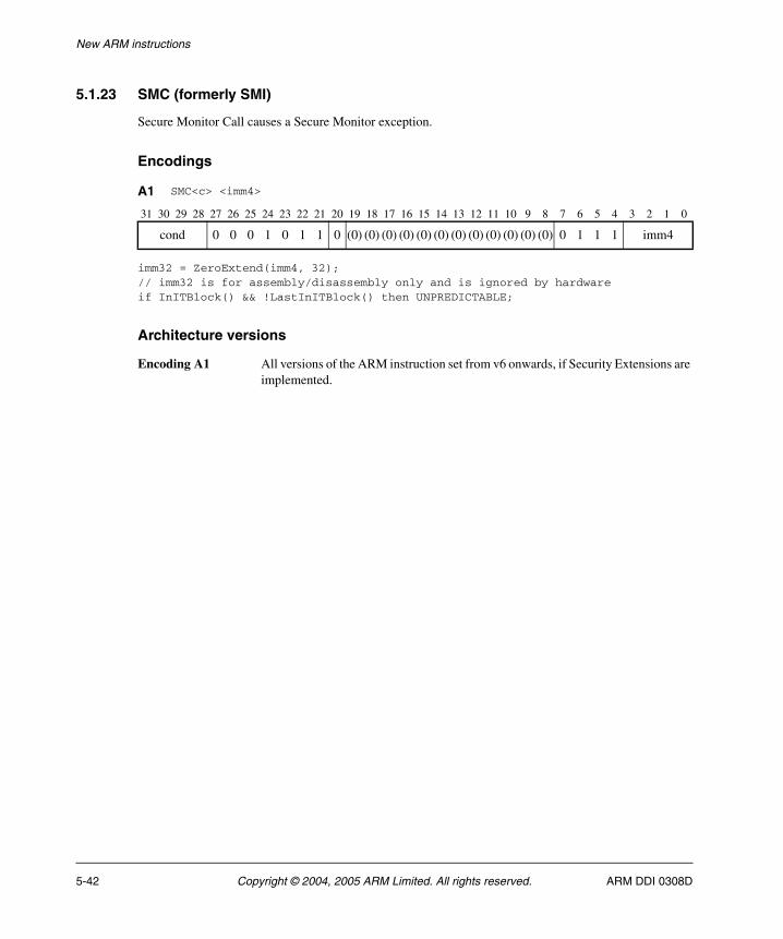
New ARM instructions
5.1.23 SMC (formerly SMI)
Secure Monitor Call causes a Secure Monitor exception.
Encodings
imm32 = ZeroExtend(imm4, 32);// imm32 is for assembly/disassembly only and is ignored by hardwareif InITBlock() && !LastInITBlock() then UNPREDICTABLE;
Architecture versions
Encoding A1 All versions of the ARM instruction set from v6 onwards, if Security Extensions are implemented.
A1 SMC<c> <imm4>
31 30 29 28 27 26 25 24 23 22 21 20 19 18 17 16 15 14 13 12 11 10 9 8 7 6 5 4 3 2 1 0
cond 0 0 0 1 0 1 1 0 (0) (0) (0) (0) (0) (0) (0) (0) (0) (0) (0) (0) 0 1 1 1 imm4
5-42 Copyright © 2004, 2005 ARM Limited. All rights reserved. ARM DDI 0308D
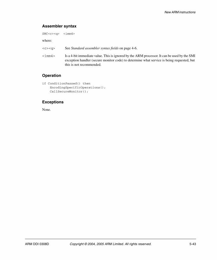
New ARM instructions
Assembler syntax
SMC<c><q> <imm4>
where:
<c><q> See Standard assembler syntax fields on page 4-6.
<imm4> Is a 4-bit immediate value. This is ignored by the ARM processor. It can be used by the SMI exception handler (secure monitor code) to determine what service is being requested, but this is not recommended.
Operation
if ConditionPassed() then EncodingSpecificOperations(); CallSecureMonitor();
Exceptions
None.
ARM DDI 0308D Copyright © 2004, 2005 ARM Limited. All rights reserved. 5-43
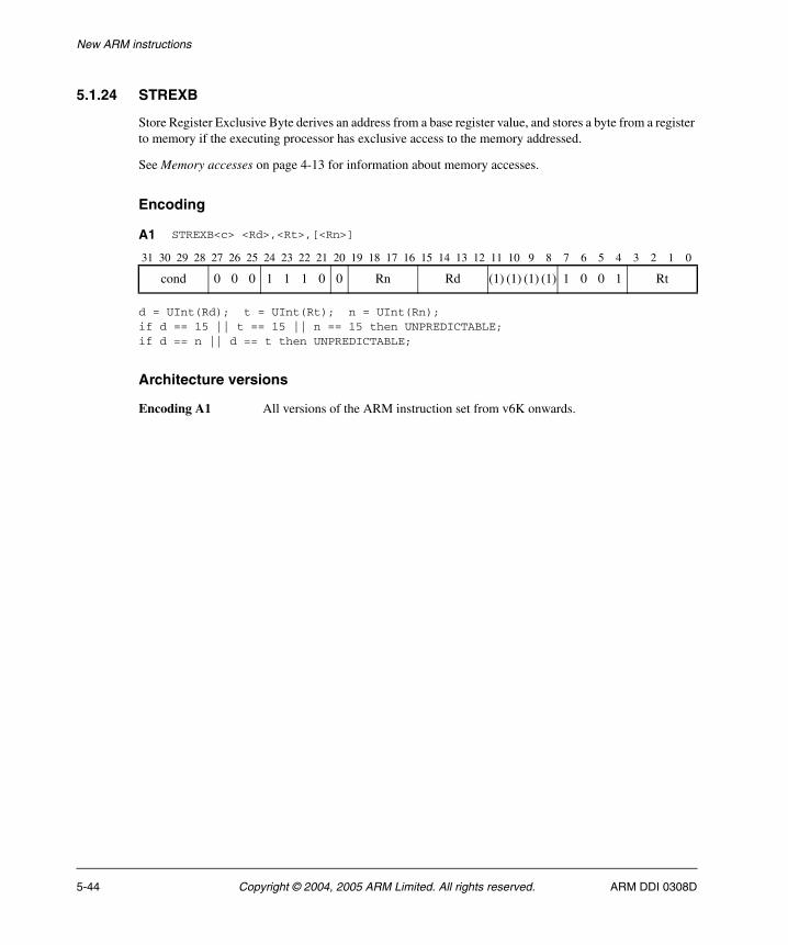
New ARM instructions
5.1.24 STREXB
Store Register Exclusive Byte derives an address from a base register value, and stores a byte from a register to memory if the executing processor has exclusive access to the memory addressed.
See Memory accesses on page 4-13 for information about memory accesses.
Encoding
d = UInt(Rd); t = UInt(Rt); n = UInt(Rn);if d == 15 || t == 15 || n == 15 then UNPREDICTABLE;if d == n || d == t then UNPREDICTABLE;
Architecture versions
Encoding A1 All versions of the ARM instruction set from v6K onwards.
A1 STREXB<c> <Rd>,<Rt>,[<Rn>]
31 30 29 28 27 26 25 24 23 22 21 20 19 18 17 16 15 14 13 12 11 10 9 8 7 6 5 4 3 2 1 0
cond 0 0 0 1 1 1 0 0 Rn Rd (1) (1) (1) (1) 1 0 0 1 Rt
5-44 Copyright © 2004, 2005 ARM Limited. All rights reserved. ARM DDI 0308D
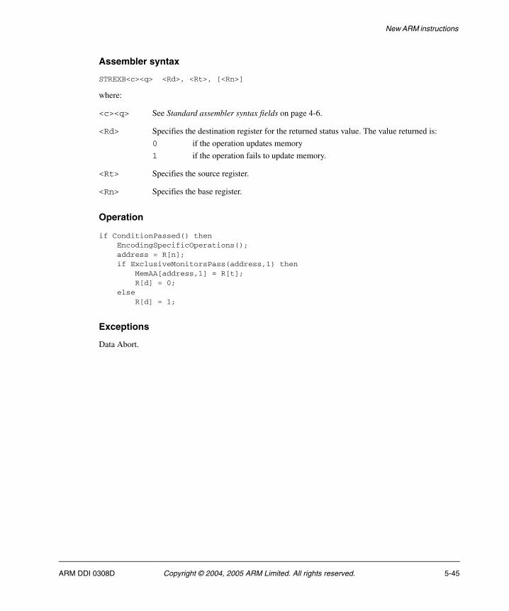
New ARM instructions
Assembler syntax
STREXB<c><q> <Rd>, <Rt>, [<Rn>]
where:
<c><q> See Standard assembler syntax fields on page 4-6.
<Rd> Specifies the destination register for the returned status value. The value returned is:
0 if the operation updates memory
1 if the operation fails to update memory.
<Rt> Specifies the source register.
<Rn> Specifies the base register.
Operation
if ConditionPassed() then EncodingSpecificOperations(); address = R[n]; if ExclusiveMonitorsPass(address,1) then MemAA[address,1] = R[t]; R[d] = 0; else R[d] = 1;
Exceptions
Data Abort.
ARM DDI 0308D Copyright © 2004, 2005 ARM Limited. All rights reserved. 5-45
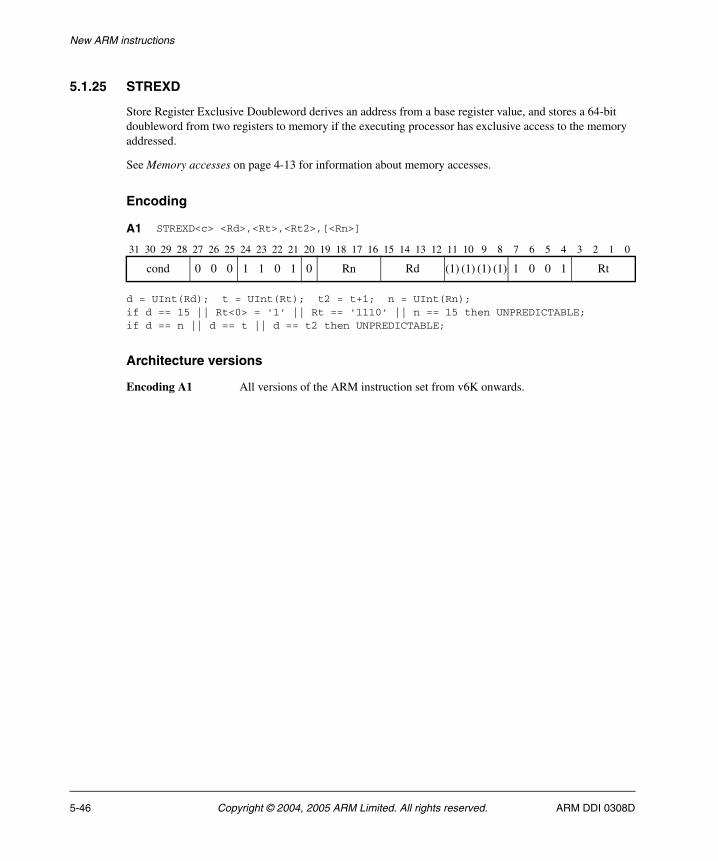
New ARM instructions
5.1.25 STREXD
Store Register Exclusive Doubleword derives an address from a base register value, and stores a 64-bit doubleword from two registers to memory if the executing processor has exclusive access to the memory addressed.
See Memory accesses on page 4-13 for information about memory accesses.
Encoding
d = UInt(Rd); t = UInt(Rt); t2 = t+1; n = UInt(Rn);if d == 15 || Rt<0> = '1' || Rt == '1110' || n == 15 then UNPREDICTABLE;if d == n || d == t || d == t2 then UNPREDICTABLE;
Architecture versions
Encoding A1 All versions of the ARM instruction set from v6K onwards.
A1 STREXD<c> <Rd>,<Rt>,<Rt2>,[<Rn>]
31 30 29 28 27 26 25 24 23 22 21 20 19 18 17 16 15 14 13 12 11 10 9 8 7 6 5 4 3 2 1 0
cond 0 0 0 1 1 0 1 0 Rn Rd (1) (1) (1) (1) 1 0 0 1 Rt
5-46 Copyright © 2004, 2005 ARM Limited. All rights reserved. ARM DDI 0308D
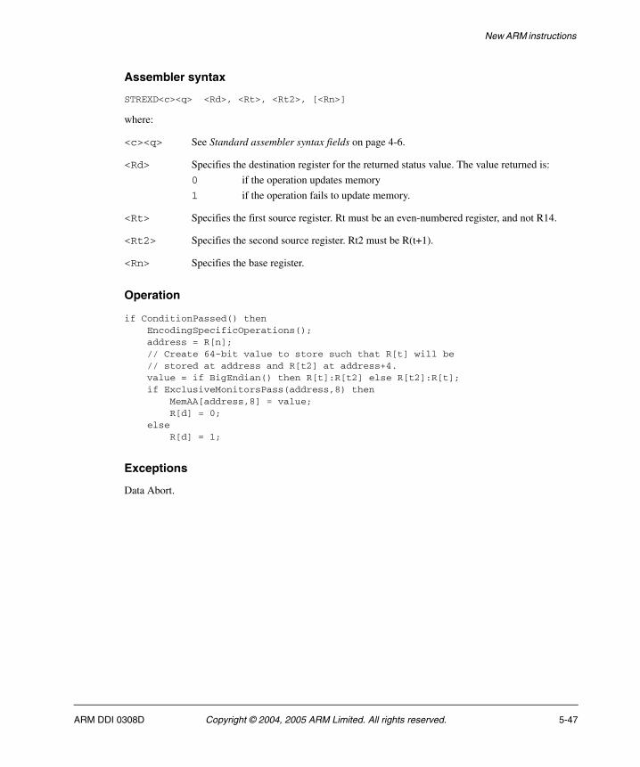
New ARM instructions
Assembler syntax
STREXD<c><q> <Rd>, <Rt>, <Rt2>, [<Rn>]
where:
<c><q> See Standard assembler syntax fields on page 4-6.
<Rd> Specifies the destination register for the returned status value. The value returned is:
0 if the operation updates memory
1 if the operation fails to update memory.
<Rt> Specifies the first source register. Rt must be an even-numbered register, and not R14.
<Rt2> Specifies the second source register. Rt2 must be R(t+1).
<Rn> Specifies the base register.
Operation
if ConditionPassed() then EncodingSpecificOperations(); address = R[n]; // Create 64-bit value to store such that R[t] will be // stored at address and R[t2] at address+4. value = if BigEndian() then R[t]:R[t2] else R[t2]:R[t]; if ExclusiveMonitorsPass(address,8) then MemAA[address,8] = value; R[d] = 0; else R[d] = 1;
Exceptions
Data Abort.
ARM DDI 0308D Copyright © 2004, 2005 ARM Limited. All rights reserved. 5-47
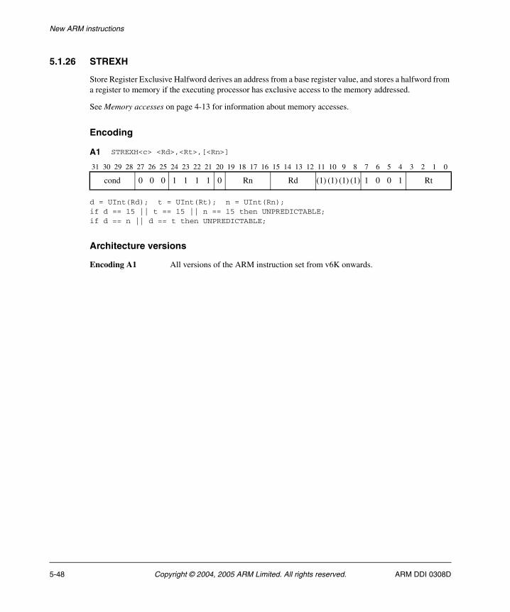
New ARM instructions
5.1.26 STREXH
Store Register Exclusive Halfword derives an address from a base register value, and stores a halfword from a register to memory if the executing processor has exclusive access to the memory addressed.
See Memory accesses on page 4-13 for information about memory accesses.
Encoding
d = UInt(Rd); t = UInt(Rt); n = UInt(Rn);if d == 15 || t == 15 || n == 15 then UNPREDICTABLE;if d == n || d == t then UNPREDICTABLE;
Architecture versions
Encoding A1 All versions of the ARM instruction set from v6K onwards.
A1 STREXH<c> <Rd>,<Rt>,[<Rn>]
31 30 29 28 27 26 25 24 23 22 21 20 19 18 17 16 15 14 13 12 11 10 9 8 7 6 5 4 3 2 1 0
cond 0 0 0 1 1 1 1 0 Rn Rd (1) (1) (1) (1) 1 0 0 1 Rt
5-48 Copyright © 2004, 2005 ARM Limited. All rights reserved. ARM DDI 0308D

New ARM instructions
Assembler syntax
STREXH<c><q> <Rd>, <Rt>, [<Rn>]
where:
<c><q> See Standard assembler syntax fields on page 4-6.
<Rd> Specifies the destination register for the returned status value. The value returned is:
0 if the operation updates memory
1 if the operation fails to update memory.
<Rt> Specifies the source register.
<Rn> Specifies the base register.
Operation
if ConditionPassed() then EncodingSpecificOperations(); address = R[n]; if ExclusiveMonitorsPass(address,2) then MemAA[address,2] = R[t]; R[d] = 0; else R[d] = 1;
Exceptions
Data Abort.
ARM DDI 0308D Copyright © 2004, 2005 ARM Limited. All rights reserved. 5-49
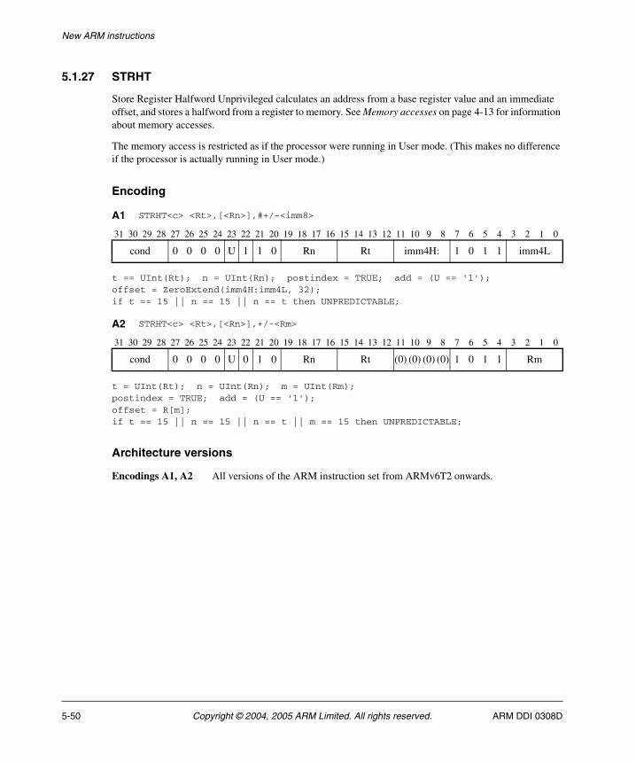
New ARM instructions
5.1.27 STRHT
Store Register Halfword Unprivileged calculates an address from a base register value and an immediate offset, and stores a halfword from a register to memory. See Memory accesses on page 4-13 for information about memory accesses.
The memory access is restricted as if the processor were running in User mode. (This makes no difference if the processor is actually running in User mode.)
Encoding
t == UInt(Rt); n = UInt(Rn); postindex = TRUE; add = (U == '1');offset = ZeroExtend(imm4H:imm4L, 32);if t == 15 || n == 15 || n == t then UNPREDICTABLE;
t = UInt(Rt); n = UInt(Rn); m = UInt(Rm);postindex = TRUE; add = (U == '1');offset = R[m];if t == 15 || n == 15 || n == t || m == 15 then UNPREDICTABLE;
Architecture versions
Encodings A1, A2 All versions of the ARM instruction set from ARMv6T2 onwards.
A1 STRHT<c> <Rt>,[<Rn>],#+/-<imm8>
31 30 29 28 27 26 25 24 23 22 21 20 19 18 17 16 15 14 13 12 11 10 9 8 7 6 5 4 3 2 1 0
cond 0 0 0 0 U 1 1 0 Rn Rt imm4H: 1 0 1 1 imm4L
A2 STRHT<c> <Rt>,[<Rn>],+/-<Rm>
31 30 29 28 27 26 25 24 23 22 21 20 19 18 17 16 15 14 13 12 11 10 9 8 7 6 5 4 3 2 1 0
cond 0 0 0 0 U 0 1 0 Rn Rt (0) (0) (0) (0) 1 0 1 1 Rm
5-50 Copyright © 2004, 2005 ARM Limited. All rights reserved. ARM DDI 0308D
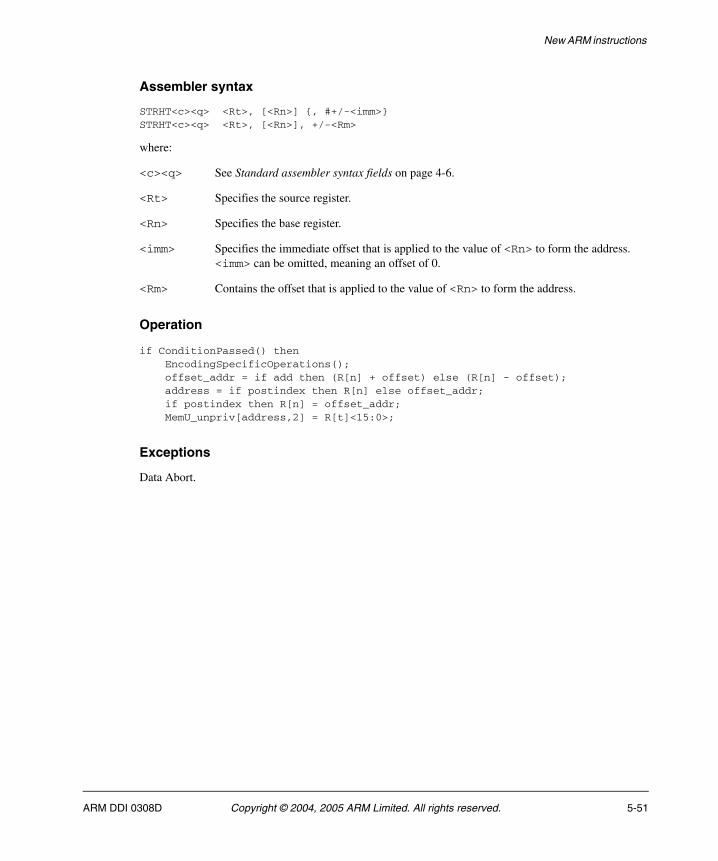
New ARM instructions
Assembler syntax
STRHT<c><q> <Rt>, [<Rn>] {, #+/-<imm>}STRHT<c><q> <Rt>, [<Rn>], +/-<Rm>
where:
<c><q> See Standard assembler syntax fields on page 4-6.
<Rt> Specifies the source register.
<Rn> Specifies the base register.
<imm> Specifies the immediate offset that is applied to the value of <Rn> to form the address. <imm> can be omitted, meaning an offset of 0.
<Rm> Contains the offset that is applied to the value of <Rn> to form the address.
Operation
if ConditionPassed() then EncodingSpecificOperations(); offset_addr = if add then (R[n] + offset) else (R[n] - offset); address = if postindex then R[n] else offset_addr; if postindex then R[n] = offset_addr; MemU_unpriv[address,2] = R[t]<15:0>;
Exceptions
Data Abort.
ARM DDI 0308D Copyright © 2004, 2005 ARM Limited. All rights reserved. 5-51
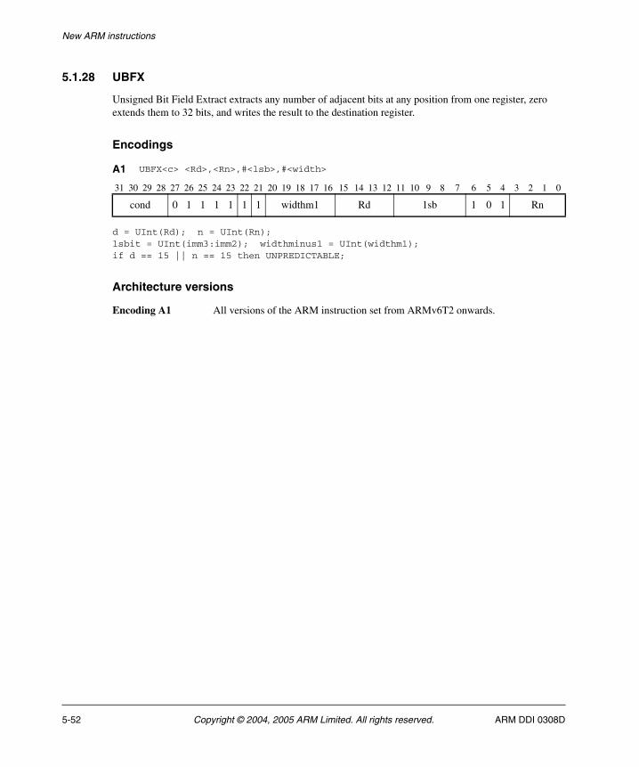
New ARM instructions
5.1.28 UBFX
Unsigned Bit Field Extract extracts any number of adjacent bits at any position from one register, zero extends them to 32 bits, and writes the result to the destination register.
Encodings
d = UInt(Rd); n = UInt(Rn);lsbit = UInt(imm3:imm2); widthminus1 = UInt(widthm1);if d == 15 || n == 15 then UNPREDICTABLE;
Architecture versions
Encoding A1 All versions of the ARM instruction set from ARMv6T2 onwards.
A1 UBFX<c> <Rd>,<Rn>,#<lsb>,#<width>
31 30 29 28 27 26 25 24 23 22 21 20 19 18 17 16 15 14 13 12 11 10 9 8 7 6 5 4 3 2 1 0
cond 0 1 1 1 1 1 1 widthm1 Rd 1sb 1 0 1 Rn
5-52 Copyright © 2004, 2005 ARM Limited. All rights reserved. ARM DDI 0308D

New ARM instructions
Assembler syntax
UBFX<c><q> <Rd>, <Rn>, #<lsb>, #<width>
where:
<c><q> See Standard assembler syntax fields on page 4-6.
<Rd> Specifies the destination register.
<Rn> Specifies the register that contains the first operand.
<lsb> is the bit number of the least significant bit in the bitfield (in the range 0-31).
<width> is the width of the bitfield (in the range 1-32).
Operation
if ConditionPassed() then EncodingSpecificOperations(); msbit = lsbit + widthminus1; if msbit <= 31 then R[d] = ZeroExtend(R[n]<msbit:lsbit>, 32); else UNPREDICTABLE;
Exceptions
None.
ARM DDI 0308D Copyright © 2004, 2005 ARM Limited. All rights reserved. 5-53
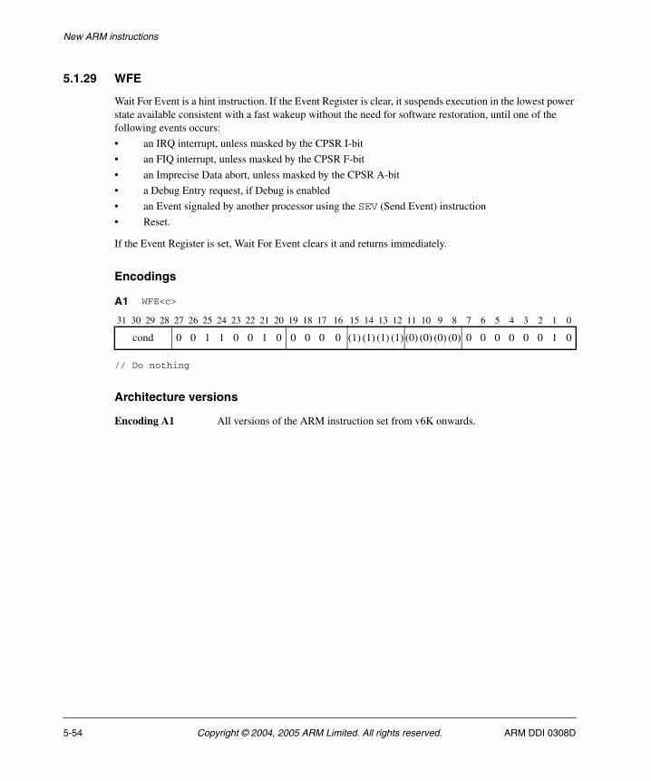
New ARM instructions
5.1.29 WFE
Wait For Event is a hint instruction. If the Event Register is clear, it suspends execution in the lowest power state available consistent with a fast wakeup without the need for software restoration, until one of the following events occurs:
• an IRQ interrupt, unless masked by the CPSR I-bit
• an FIQ interrupt, unless masked by the CPSR F-bit
• an Imprecise Data abort, unless masked by the CPSR A-bit
• a Debug Entry request, if Debug is enabled
• an Event signaled by another processor using the SEV (Send Event) instruction
• Reset.
If the Event Register is set, Wait For Event clears it and returns immediately.
Encodings
// Do nothing
Architecture versions
Encoding A1 All versions of the ARM instruction set from v6K onwards.
A1 WFE<c>
31 30 29 28 27 26 25 24 23 22 21 20 19 18 17 16 15 14 13 12 11 10 9 8 7 6 5 4 3 2 1 0
cond 0 0 1 1 0 0 1 0 0 0 0 0 (1) (1) (1) (1) (0) (0) (0) (0) 0 0 0 0 0 0 1 0
5-54 Copyright © 2004, 2005 ARM Limited. All rights reserved. ARM DDI 0308D
New ARM instructions
Assembler syntax
WFE<c><q>
where:
<c><q> See Standard assembler syntax fields on page 4-6.
Operation
if ConditionPassed() then EncodingSpecificOperations(); if EventRegistered() then ClearEventRegister(); else WaitForEvent();
Exceptions
None.
ARM DDI 0308D Copyright © 2004, 2005 ARM Limited. All rights reserved. 5-55
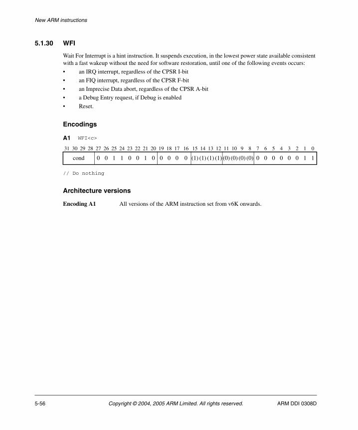
New ARM instructions
5.1.30 WFI
Wait For Interrupt is a hint instruction. It suspends execution, in the lowest power state available consistent with a fast wakeup without the need for software restoration, until one of the following events occurs:
• an IRQ interrupt, regardless of the CPSR I-bit
• an FIQ interrupt, regardless of the CPSR F-bit
• an Imprecise Data abort, regardless of the CPSR A-bit
• a Debug Entry request, if Debug is enabled
• Reset.
Encodings
// Do nothing
Architecture versions
Encoding A1 All versions of the ARM instruction set from v6K onwards.
A1 WFI<c>
31 30 29 28 27 26 25 24 23 22 21 20 19 18 17 16 15 14 13 12 11 10 9 8 7 6 5 4 3 2 1 0
cond 0 0 1 1 0 0 1 0 0 0 0 0 (1) (1) (1) (1) (0) (0) (0) (0) 0 0 0 0 0 0 1 1
5-56 Copyright © 2004, 2005 ARM Limited. All rights reserved. ARM DDI 0308D
New ARM instructions
Assembler syntax
WFI<c><q>
where:
<c><q> See Standard assembler syntax fields on page 4-6.
Operation
if ConditionPassed() then EncodingSpecificOperations(); WaitForInterrupt();
Exceptions
None.
ARM DDI 0308D Copyright © 2004, 2005 ARM Limited. All rights reserved. 5-57
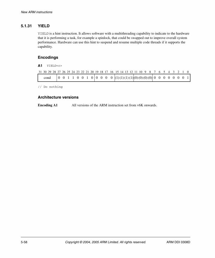
New ARM instructions
5.1.31 YIELD
YIELD is a hint instruction. It allows software with a multithreading capability to indicate to the hardware that it is performing a task, for example a spinlock, that could be swapped out to improve overall system performance. Hardware can use this hint to suspend and resume multiple code threads if it supports the capability.
Encodings
// Do nothing
Architecture versions
Encoding A1 All versions of the ARM instruction set from v6K onwards.
A1 YIELD<c>
31 30 29 28 27 26 25 24 23 22 21 20 19 18 17 16 15 14 13 12 11 10 9 8 7 6 5 4 3 2 1 0
cond 0 0 1 1 0 0 1 0 0 0 0 0 (1) (1) (1) (1) (0) (0) (0) (0) 0 0 0 0 0 0 0 1
5-58 Copyright © 2004, 2005 ARM Limited. All rights reserved. ARM DDI 0308D
New ARM instructions
Assembler syntax
YIELD<c><q>
where:
<c><q> See Standard assembler syntax fields on page 4-6.
Operation
if ConditionPassed() then EncodingSpecificOperations(); Hint_Yield();
Exceptions
None.
ARM DDI 0308D Copyright © 2004, 2005 ARM Limited. All rights reserved. 5-59

New ARM instructions
5-60 Copyright © 2004, 2005 ARM Limited. All rights reserved. ARM DDI 0308D
Appendix A Pseudo-code definition
This appendix provides a formal definition of the pseudo-code used in this book, and lists the helper procedures and functions used by pseudo-code to perform useful architecture-specific jobs. It contains the following sections:
• Instruction encoding diagrams and pseudo-code on page A-2
• Data Types on page A-4
• Expressions on page A-8
• Operators and built-in functions on page A-10
• Statements and program structure on page A-18
• Helper procedures and functions on page A-22.
ARM DDI 0308D Copyright © 2004, 2005 ARM Limited. All rights reserved. A-1
Pseudo-code definition
A.1 Instruction encoding diagrams and pseudo-code
Instruction descriptions in this book contain:
• An Encoding section, containing one or more encoding diagrams, each followed by some encoding-specific pseudo-code that translates the fields of the encoding into inputs for the common pseudo-code of the instruction, and picks out any encoding-specific special cases.
• An Operation section, containing common pseudo-code that applies to all of the encodings being described. The Operation section pseudo-code contains a call to the EncodingSpecificOperations() function, either at its start or after only a condition check performed by if ConditionPassed() then.
An encoding diagram specifies each bit of the instruction as one of the following:
• An obligatory 0 or 1, represented in the diagram as 0 or 1. If this bit does not have this value, the encoding corresponds to a different instruction.
• A should be 0 or 1, represented in the diagram as (0) or (1). If this bit does not have this value, the instruction is UNPREDICTABLE.
• A named single bit or a bit within a named multi-bit field. The cond field in bits[31:28] of many ARM instructions has some special rules associated with it.
An encoding diagram matches an instruction if all obligatory bits are identical in the encoding diagram and the instruction, and one of the following is true:
• the encoding diagram is not for an ARM instruction
• the encoding diagram is for an ARM instruction that does not have a cond field in bits[31:28]
• the encoding diagram is for an ARM instruction that has a cond field in bits[31:28], and bits[31:28] of the instruction are not 0b1111.
The execution model for an instruction is:
1. Find all encoding diagrams that match the instruction. It is possible that no encoding diagrams match. In that case, abandon this execution model and consult the relevant instruction set chapter instead to find out how the instruction is to be treated. (The bit pattern of such an instruction is usually reserved and UNDEFINED, though there are some other possibilities. For example, unallocated hint instructions are documented as being reserved and to be executed as NOPs.)
2. If the common pseudo-code for the matching encoding diagrams starts with a condition check, perform that condition check. If the condition check fails, abandon this execution model and treat the instruction as a NOP. (If there are multiple matching encoding diagrams, either all or none of their corresponding pieces of common pseudo-code start with a condition check.)
A-2 Copyright © 2004, 2005 ARM Limited. All rights reserved. ARM DDI 0308D
Pseudo-code definition
3. Perform the encoding-specific pseudo-code for each of the matching encoding diagrams independently and in parallel. Each such piece of encoding-specific pseudo-code starts with a bitstring variable for each named bit or multi-bit field within its corresponding encoding diagram, named the same as the bit or multi-bit field and initialized with the values of the corresponding bit(s) from the bit pattern of the instruction.
If there are multiple matching encoding diagrams, all but one of the corresponding pieces of pseudo-code must contain a special case that indicates that it does not apply. Discard the results of all such pieces of pseudo-code and their corresponding encoding diagrams.
There is now one remaining piece of pseudo-code and its corresponding encoding diagram left to consider. This pseudo-code might also contain a special case (most commonly one indicating that it is UNPREDICTABLE). If so, abandon this execution model and treat the instruction according to the special case.
4. Check the should be bits of the encoding diagram against the corresponding bits of the bit pattern of the instruction. If any of them do not match, abandon this execution model and treat the instruction as UNPREDICTABLE.
5. Perform the rest of the common pseudo-code for the instruction description that contains the encoding diagram. That pseudo-code starts with all variables set to the values they were left with by the encoding-specific pseudo-code.
The ConditionPassed() call in the common pseudo-code (if present) performs step 2, and the EncodingSpecificOperations() call performs steps 3 and 4.
A.1.1 Pseudo-code
The pseudo-code provides precise descriptions of what instructions do. Instruction fields are referred to by the names shown in the encoding diagram for the instruction.
The pseudo-code is described in detail in the following sections.
ARM DDI 0308D Copyright © 2004, 2005 ARM Limited. All rights reserved. A-3

Pseudo-code definition
A.2 Data Types
This section describes:
• General data type rules
• Bitstrings
• Integers on page A-5
• Reals on page A-5
• Booleans on page A-5
• Enumerations on page A-5
• Lists on page A-6
• Arrays on page A-7.
A.2.1 General data type rules
ARM Architecture pseudo-code is a strongly-typed language. Every constant and variable is of one of the following types:
• bitstring
• integer
• boolean
• real
• enumeration
• list
• array.
The type of a constant is determined by its syntax. The type of a variable is normally determined by assignment to the variable, with the variable being implicitly declared to be of the same type as whatever is assigned to it. For example, the assignments x = 1, y = '1', and z = TRUE implicitly declare the variables x, y and z to have types integer, length-1 bitstring and boolean respectively.
Variables can also have their types declared explicitly by preceding the variable name with the name of the type. This is most often done in function definitions for the arguments and the result of the function.
These data types are described in more detail in the following sections.
A.2.2 Bitstrings
A bitstring is a finite-length string of 0s and 1s. Each length of bitstring is a different type. The minimum allowed length of a bitstring is 1.
The type name for bitstrings of length N is bits(N). A synonym of bits(1) is bit.
Bitstring constants are written as a single quotation mark, followed by the string of 0s and 1s, followed by another single quotation mark. For example, the two constants of type bit are '0' and '1'.
A-4 Copyright © 2004, 2005 ARM Limited. All rights reserved. ARM DDI 0308D
Pseudo-code definition
Every bitstring value has a left-to-right order, with the bits being numbered in standard little-endian order. That is, the leftmost bit of a bitstring of length N is bit N-1 and its rightmost bit is bit 0. This order is used as the most-significant-to-least-significant bit order in conversions to and from integers. For bitstring constants and bitstrings derived from encoding diagrams, this order matches the way they are printed.
Bitstrings are the only concrete data type in pseudo-code, in the sense that they correspond directly to the contents of registers, memory locations, instructions, and so on. All of the remaining data types are abstract.
A.2.3 Integers
Pseudo-code integers are unbounded in size and can be either positive or negative. That is, they are mathematical integers rather than what computer languages and architectures commonly call integers. Computer integers are represented in pseudo-code as bitstrings of the appropriate length, associated with suitable functions to interpret those bitstrings as integers.
The type name for integers is integer.
Integer constants are normally written in decimal, such as 0, 15, -1234. They can also be written in C-style hexadecimal, such as 0x55 or 0x80000000. Hexadecimal integer constants are treated as positive unless they have a preceding minus sign. For example, 0x80000000 is the integer +231. If -231 needs to be written in hexadecimal, it should be written as -0x80000000.
A.2.4 Reals
Pseudo-code reals are unbounded in size and precision. That is, they are mathematical real numbers, not computer floating-point numbers. Computer floating-point numbers are represented in pseudo-code as bitstrings of the appropriate length, associated with suitable functions to interpret those bitstrings as reals.
The type name for reals is real.
Real constants are written in decimal with a decimal point (so 0 is an integer constant, but 0.0 is a real constant).
A.2.5 Booleans
A boolean is a logical true or false value.
The type name for booleans is boolean. This is not the same type as bit, which is a length-1 bitstring.
Boolean constants are TRUE and FALSE.
A.2.6 Enumerations
An enumeration is a defined set of symbolic constants, such as:
enumeration InstrSet {InstrSet_ARM, InstrSet_Thumb, InstrSet_Java, InstrSet_ThumbEE};
An enumeration always contains at least one symbolic constant, and symbolic constants are not allowed to be shared between enumerations.
ARM DDI 0308D Copyright © 2004, 2005 ARM Limited. All rights reserved. A-5
Pseudo-code definition
Enumerations must be declared explicitly, though a variable of an enumeration type can be declared implicitly as usual by assigning one of the symbolic constants to it. By convention, each of the symbolic constants starts with the name of the enumeration followed by an underscore. The name of the enumeration is its type name, and the symbolic constants are its possible constants.
Note Booleans are basically a pre-declared enumeration:
enumeration boolean {FALSE, TRUE};
that does not follow the normal naming convention and that has a special role in some pseudo-code constructs, such as if statements.
A.2.7 Lists
A list is an ordered set of other data items, separated by commas and enclosed in parentheses, such as:
(bits(32) shifter_result, bit shifter_carry_out)
A list always contains at least one data item.
Lists are often used as the return type for a function that returns multiple results. For example, this particular list is the return type of the function Shift_C() that performs a standard ARM shift or rotation, when its first operand is of type bits(32).
Some specific pseudo-code operators use lists surrounded by other forms of bracketing than parentheses. These are:
• Bitstring extraction operators, which use lists of bit numbers or ranges of bit numbers surrounded by angle brackets "<...>".
• Array indexing, which uses lists of array indexes surrounded by square brackets "[...]".
• Array-like function argument passing, which uses lists of function arguments surrounded by square brackets "[...]".
Each combination of data types in a list is a separate type, with type name given by just listing the data types (that is, (bits(32),bit) in the above example). The general principle that types can be declared by assignment extends to the types of the individual list items within a list. For example:
(shift_t, shift_n) = ('00', 0);
implicitly declares shift_t, shift_n and (shift_t,shift_n) to be of types bits(2), integer and (bits(2),integer) respectively.
A list type can also be explicitly named, with explicitly named elements in the list. For example:
type ShiftSpec is (bits(2) shift, integer amount);
After this definition and the declaration:
A-6 Copyright © 2004, 2005 ARM Limited. All rights reserved. ARM DDI 0308D
Pseudo-code definition
ShiftSpec abc;
the elements of the resulting list can then be referred to as "abc.shift" and "abc.amount". This sort of qualified naming of list elements is only permitted for variables that have been explicitly declared, not for those that have been declared by assignment only.
Explicitly naming a type does not alter what type it is. For example, after the above definition of ShiftSpec, ShiftSpec and (bits(2),integer) are two different names for the same type, not the names of two different types. In order to avoid ambiguity in references to list elements, it is an error to declare a list variable multiple times using different names of its type or to qualify it with list element names not associated with the name by which it was declared.
An item in a list that is being assigned to may be written as "-" to indicate that the corresponding item of the assigned list value is discarded. For example:
(shifted, -) = LSL_C(operand, amount);
List constants are written as a list of constants of the appropriate types, like ('00', 0) in the above example.
A.2.8 Arrays
Pseudo-code arrays are indexed by either enumerations or integer ranges (represented by the lower inclusive end of the range, then "..", then the upper inclusive end of the range). For example:
enumeration PhysReg { PhysReg_R0, PhysReg_R1, PhysReg_R2, PhysReg_R3, PhysReg_R4, PhysReg_R5, PhysReg_R6, PhysReg_R7, PhysReg_R8, PhysReg_R8fiq, PhysReg_R9, PhysReg_R9fiq, PhysReg_R10, PhysReg_R10fiq, PhysReg_R11, PhysReg_R11fiq, PhysReg_R12, PhysReg_R12fiq, PhysReg_SP, PhysReg_SPfiq, PhysReg_SPirq, PhysReg_SPsvc, PhysReg_SPabt, PhysReg_SPund, PhysReg_SPmon, PhysReg_LR, PhysReg_LRfiq, PhysReg_LRirq, PhysReg_LRsvc, PhysReg_LRabt, PhysReg_LRund, PhysReg_LRmon, PhysReg_PC};
array bits(32) _R[PhysReg];
array bits(8) _Memory[0..0xFFFFFFFF];
Arrays are always explicitly declared, and there is no notation for a constant array. Arrays always contain at least one element, because enumerations always contain at least one symbolic constant and integer ranges always contain at least one integer.
Arrays do not usually appear directly in pseudo-code. The items that syntactically look like arrays in pseudo-code are usually array-like functions such as R[i], MemU[address,size] or Element[i,type]. These functions package up and abstract additional operations normally performed on accesses to the underlying arrays, such as register banking, memory protection, endian-dependent byte ordering, exclusive-access housekeeping and Neon element processing.
ARM DDI 0308D Copyright © 2004, 2005 ARM Limited. All rights reserved. A-7
Pseudo-code definition
A.3 Expressions
This section describes:
• General expression syntax
• Operators and functions - polymorphism and prototypes on page A-9
• Precedence rules on page A-9.
A.3.1 General expression syntax
An expression is one of the following:
• a constant
• a variable, optionally preceded by a data type name to declare its type
• the word UNKNOWN preceded by a data type name to declare its type
• the result of applying a language-defined operator to other expressions
• the result of applying a function to other expressions.
An expression like "bits(32) UNKNOWN" indicates that the result of the expression is a value of the given type, but the architecture does not specify what value it is and software must not rely on such values. The value produced must not constitute a security hole and must not be promoted as providing any useful information to software. (This was called an UNPREDICTABLE value in previous ARM Architecture documentation. It is related to but not the same as UNPREDICTABLE, which says that the entire architectural state becomes similarly unspecified.)
A subset of expressions are assignable. That is, they can be placed on the left-hand side of an assignment. This subset consists of:
• Variables
• The results of applying some operators to other expressions. The description of each language-defined operator that can generate an assignable expression specifies the circumstances under which it does so. (For example, those circumstances might include one or more of the expressions the operator operates on themselves being assignable expressions.)
• The results of applying array-like functions to other expressions. The description of an array-like function specifies the circumstances under which it can generate an assignable expression.
Every expression has a data type. This is determined by:
• For a constant, the syntax of the constant.
• For a variable, there are three possible sources for the type
— its optional preceding data type name
— a data type it was given earlier in the pseudo-code by recursive application of this rule
— a data type it is being given by assignment (either by direct assignment to it, or by assignment to a list of which it is a member).
It is a pseudo-code error if none of these data type sources exists for a variable, or if more than one of them exists and they do not agree about the type.
A-8 Copyright © 2004, 2005 ARM Limited. All rights reserved. ARM DDI 0308D
Pseudo-code definition
• For a language-defined operator, the definition of the operator.
• For a function, the definition of the function.
A.3.2 Operators and functions - polymorphism and prototypes
Operators and functions in pseudo-code can be polymorphic, producing different functionality when applied to different data types. Each of the resulting forms of an operator or function has a different prototype definition. For example, the operator + has forms that act on various combinations of integers, reals and bitstrings.
One particularly common form of polymorphism is between bitstrings of different lengths. This is represented by using bits(N), bits(M), and so on, in the prototype definition.
A.3.3 Precedence rules
The precedence rules for expressions are:
1. Constants, variables and function invocations are evaluated with higher priority than any operators using their results.
2. Expressions on integers follow the normal exponentiation before multiply/divide before add/subtract operator precedence rules, with sequences of multiply/divides or add/subtracts evaluated left-to-right.
3. Other expressions must be parenthesized to indicate operator precedence if ambiguity is possible, but need not be if all allowable precedence orders under the type rules necessarily lead to the same result. For example, if i, j and k are integer variables, i > 0 && j > 0 && k > 0 is acceptable, but i > 0 && j > 0 || k > 0 is not.
ARM DDI 0308D Copyright © 2004, 2005 ARM Limited. All rights reserved. A-9
Pseudo-code definition
A.4 Operators and built-in functions
This section describes:
• Operations on generic types
• Operations on booleans
• Bitstring manipulation
• Arithmetic on page A-14.
A.4.1 Operations on generic types
The following operations are defined for all types.
Equality and non-equality testing
Any two values x and y of the same type can be tested for equality by the expression x == y and for non-equality by the expression x != y. In both cases, the result is of type boolean.
Conditional selection
If x and y are two values of the same type and t is a value of type boolean, then if t then x else y is an expression of the same type as x and y that produces x if t is TRUE and y if t is FALSE.
A.4.2 Operations on booleans
If x is a boolean, then !x is its logical inverse.
If x and y are booleans, then x && y is the result of ANDing them together. As in the C language, if x is FALSE, the result is determined to be FALSE without evaluating y.
If x and y are booleans, then x || y is the result of ORing them together. As in the C language, if x is TRUE, the result is determined to be TRUE without evaluating y.
If x and y are booleans, then x ^ y is the result of exclusive-ORing them together.
A.4.3 Bitstring manipulation
The following bitstring manipulation functions are defined:
Bitstring length and top bit
If x is a bitstring, the bitstring length function Len(x) returns its length as an integer, and TopBit(x) is the leftmost bit of x (= x<Len(x)-1> using bitstring extraction.
A-10 Copyright © 2004, 2005 ARM Limited. All rights reserved. ARM DDI 0308D
Pseudo-code definition
Bitstring concatenation and replication
If x and y are bitstrings of lengths N and M respectively, then x:y is the bitstring of length N+M constructed by concatenating x and y in left-to-right order.
If x is a bitstring and n is an integer with n > 0, Replicate(x,n) is the bitstring of length n*Len(x) consisting of n copies of x concatenated together.
Bitstring extraction
The bitstring extraction operator extracts a bitstring from either another bitstring or an integer. Its syntax is x<integer_list>, where x is the integer or bitstring being extracted from, and <integer_list> is a list of integers enclosed in angle brackets rather than the usual parentheses. The length of the resulting bitstring is equal to the number of integers in <integer_list>.
In x<integer_list>, each of the integers in <integer_list> must be:
• >= 0
• < Len(x) if x is a bitstring.
The definition of x<integer_list> depends on whether integer_list contains more than one integer. If it does, x<i,j,k,...,n> is defined to be the concatenation:
x<i> : x<j> : x<k> : ... : x<n>
If integer_list consists of just one integer i, x<i> is defined to be:
• if x is a bitstring, '0' if bit i of x is a zero and '1' if bit i of x is a one.
• if x is an integer, let y be the unique integer in the range 0 to 2^(i+1)-1 that is congruent to x modulo 2^(i+1). Then x<i> is '0' if y < 2^i and '1' if y >= 2^i.
Loosely, this second definition treats an integer as equivalent to a sufficiently long 2's complement representation of it as a bitstring.
In <integer_list>, the notation i:j with i >= j is shorthand for the integers in order from i down to j, both ends inclusive. For example, instr<31:28> is shorthand for instr<31,30,29,28>.
The expression x<integer_list> is assignable provided x is an assignable bitstring and no integer appears more than once in <integer_list>. In particular, x<i> is assignable if x is an assignable bitstring and 0 <= i < Len(x).
Logical operations on bitstrings
If x is a bitstring, NOT(x) is the bitstring of the same length obtained by logically inverting every bit of x.
If x and y are bitstrings of the same length, x AND y, x OR y, and x EOR y are the bitstrings of that same length obtained by logically ANDing, ORing, and exclusive-ORing corresponding bits of x and y together.
ARM DDI 0308D Copyright © 2004, 2005 ARM Limited. All rights reserved. A-11
Pseudo-code definition
Bitstring count
If x is a bitstring, BitCount(x) produces an integer result equal to the number of bits of x that are ones.
Testing a bitstring for being all zero
If x is a bitstring, IsZero(x) produces TRUE if all of the bits of x are zeros and FALSE if any of them are ones, and IsZeroBit(x) produces '1' if all of the bits of x are zeros and '0' if any of them are ones. So:
IsZero(x) = (BitCount(x) == 0)
IsZeroBit(x) = if IsZero(x) then '1' else '0'
Lowest and highest set bits of a bitstring
If x is a bitstring:
• LowestSetBit(x) is the minimum bit number of any of its bits that are ones. If all of its bits are zeros, LowestSetBit(x) = Len(x).
• HighestSetBit(x) is the maximum bit number of any of its bits that are ones. If all of its bits are zeros, HighestSetBit(x) = -1.
Zero-extension and sign-extension of bitstrings
If x is a bitstring and i is an integer, then ZeroExtend(x,i) is x extended to a length of i bits, by adding sufficient zero bits to its left. That is, if i == Len(x), then ZeroExtend(x,i) = x, and if i > Len(x), then:
ZeroExtend(x,i) = Replicate('0', i-Len(x)) : x
If x is a bitstring and i is an integer, then SignExtend(x,i) is x extended to a length of i bits, by adding sufficient copies of its leftmost bit to its left. That is, if i == Len(x), then SignExtend(x,i) = x, and if i > Len(x), then:
SignExtend(x,i) = Replicate(TopBit(x), i-Len(x)) : x
It is a pseudo-code error to use either ZeroExtend(x,i) or SignExtend(x,i) in a context where it is possible that i < Len(x).
Shifting and rotating bitstrings
Functions are defined to perform logical shift left, logical shift right, arithmetic shift right, rotate left, rotate right and rotate right extended functions on bitstrings.
The first group of such functions are shifts producing a result bitstring of the same length as their bitstring operand and a carry out bit, as follows:
A-12 Copyright © 2004, 2005 ARM Limited. All rights reserved. ARM DDI 0308D
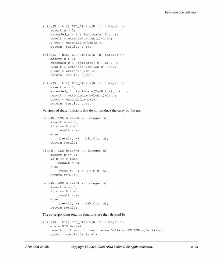
Pseudo-code definition
(bits(N), bit) LSL_C(bits(N) x, integer n) assert n > 0; extended_x = x : Replicate('0', n); result = extended_x<Len(x)-1:0>; c_out = extended_x<Len(x)>; return (result, c_out);
(bits(N), bit) LSR_C(bits(N) x, integer n) assert n > 0; extended_x = Replicate('0', n) : x; result = extended_x<n+Len(x)-1:n>; c_out = extended_x<n-1>; return (result, c_out);
(bits(N), bit) ASR_C(bits(N) x, integer n) assert n > 0; extended_x = Replicate(TopBit(x), n) : x; result = extended_x<n+Len(x)-1:n>; c_out = extended_x<n-1>; return (result, c_out);
Versions of these functions that do not produce the carry out bit are:
bits(N) LSL(bits(N) x, integer n) assert n >= 0; if n == 0 then result = x; else (result, -) = LSL_C(x, n); return result;
bits(N) LSR(bits(N) x, integer n) assert n >= 0; if n == 0 then result = x; else (result, -) = LSR_C(x, n); return result;
bits(N) ASR(bits(N) x, integer n) assert n >= 0; if n == 0 then result = x; else (result, -) = ASR_C(x, n); return result;
The corresponding rotation functions are then defined by:
(bits(N), bit) ROR_C(bits(N) x, integer n) m = n DIV Len(x); result = if m == 0 then x else LSR(x,m) OR LSL(x,Len(x)-m); c_out = result<Len(x)-1>;
ARM DDI 0308D Copyright © 2004, 2005 ARM Limited. All rights reserved. A-13
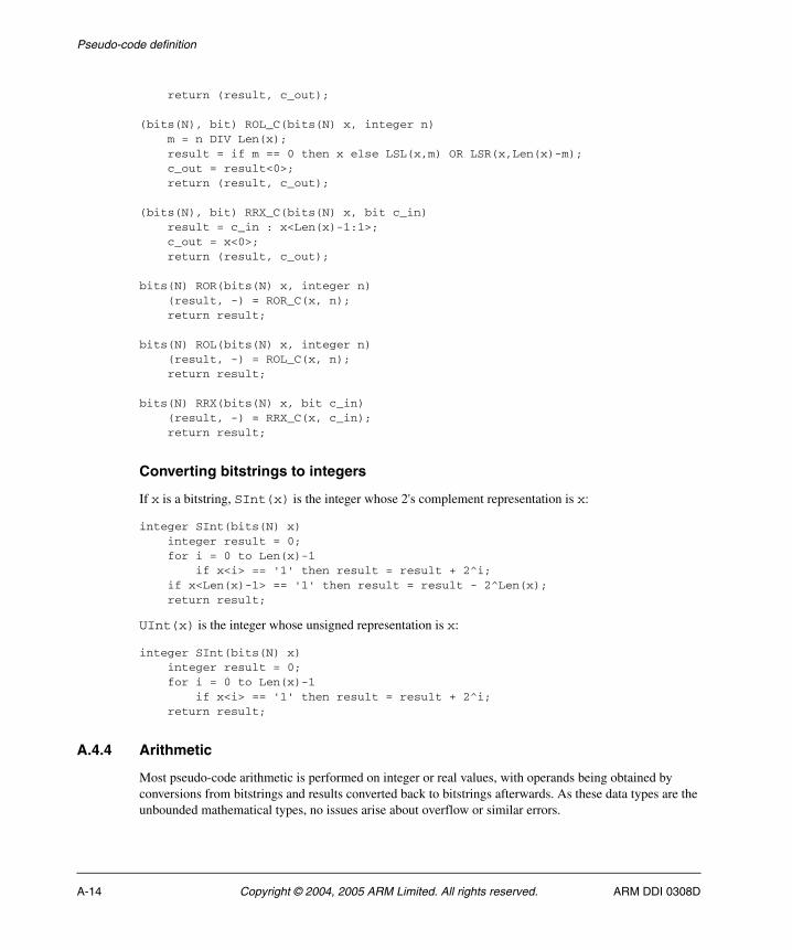
Pseudo-code definition
return (result, c_out);
(bits(N), bit) ROL_C(bits(N) x, integer n) m = n DIV Len(x); result = if m == 0 then x else LSL(x,m) OR LSR(x,Len(x)-m); c_out = result<0>; return (result, c_out);
(bits(N), bit) RRX_C(bits(N) x, bit c_in) result = c_in : x<Len(x)-1:1>; c_out = x<0>; return (result, c_out);
bits(N) ROR(bits(N) x, integer n) (result, -) = ROR_C(x, n); return result;
bits(N) ROL(bits(N) x, integer n) (result, -) = ROL_C(x, n); return result;
bits(N) RRX(bits(N) x, bit c_in) (result, -) = RRX_C(x, c_in); return result;
Converting bitstrings to integers
If x is a bitstring, SInt(x) is the integer whose 2's complement representation is x:
integer SInt(bits(N) x) integer result = 0; for i = 0 to Len(x)-1 if x<i> == '1' then result = result + 2^i; if x<Len(x)-1> == '1' then result = result - 2^Len(x); return result;
UInt(x) is the integer whose unsigned representation is x:
integer SInt(bits(N) x) integer result = 0; for i = 0 to Len(x)-1 if x<i> == '1' then result = result + 2^i; return result;
A.4.4 Arithmetic
Most pseudo-code arithmetic is performed on integer or real values, with operands being obtained by conversions from bitstrings and results converted back to bitstrings afterwards. As these data types are the unbounded mathematical types, no issues arise about overflow or similar errors.
A-14 Copyright © 2004, 2005 ARM Limited. All rights reserved. ARM DDI 0308D
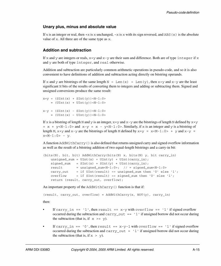
Pseudo-code definition
Unary plus, minus and absolute value
If x is an integer or real, then +x is x unchanged, -x is x with its sign reversed, and ABS(x) is the absolute value of x. All three are of the same type as x.
Addition and subtraction
If x and y are integers or reals, x+y and x-y are their sum and difference. Both are of type integer if x and y are both of type integer, and real otherwise.
Addition and subtraction are particularly common arithmetic operations in pseudo-code, and so it is also convenient to have definitions of addition and subtraction acting directly on bitstring operands.
If x and y are bitstrings of the same length N = Len(x) = Len(y), then x+y and x-y are the least significant N bits of the results of converting them to integers and adding or subtracting them. Signed and unsigned conversions produce the same result:
x+y = (SInt(x) + SInt(y))<N-1:0> = (UInt(x) + UInt(y))<N-1:0>
x-y = (SInt(x) - SInt(y))<N-1:0> = (UInt(x) - UInt(y))<N-1:0>
If x is a bitstring of length N and y is an integer, x+y and x-y are the bitstrings of length N defined by x+y = x + y<N-1:0> and x-y = x - y<N-1:0>. Similarly, if x is an integer and y is a bitstring of length M, x+y and x-y are the bitstrings of length M defined by x+y = x<M-1:0> + y and x-y = x<M-1:0> - y.
A function AddWithCarry() is also defined that returns unsigned carry and signed overflow information as well as the result of a bitstring addition of two equal-length bitstrings and a carry-in bit:
(bits(N), bit, bit) AddWithCarry(bits(N) x, bits(N) y, bit carry_in) unsigned_sum = UInt(x) + UInt(y) + UInt(carry_in); signed_sum = SInt(x) + SInt(y) + UInt(carry_in); result = unsigned_sum<N-1:0>; // = signed_sum<N-1:0> carry_out = if UInt(result) == unsigned_sum then '0' else '1'; overflow = if SInt(result) == signed_sum then '0' else '1'; return (result, carry_out, overflow);
An important property of the AddWithCarry() function is that if:
(result, carry_out, overflow) = AddWithCarry(x, NOT(y), carry_in)
then:
• If carry_in == '1', then result == x-y with overflow == '1' if signed overflow occurred during the subtraction and carry_out == '1' if unsigned borrow did not occur during the subtraction (that is, if x >= y).
• If carry_in == '0', then result == x-y-1 with overflow == '1' if signed overflow occurred during the subtraction and carry_out = '1' if unsigned borrow did not occur during the subtraction (that is, if x > y).
ARM DDI 0308D Copyright © 2004, 2005 ARM Limited. All rights reserved. A-15
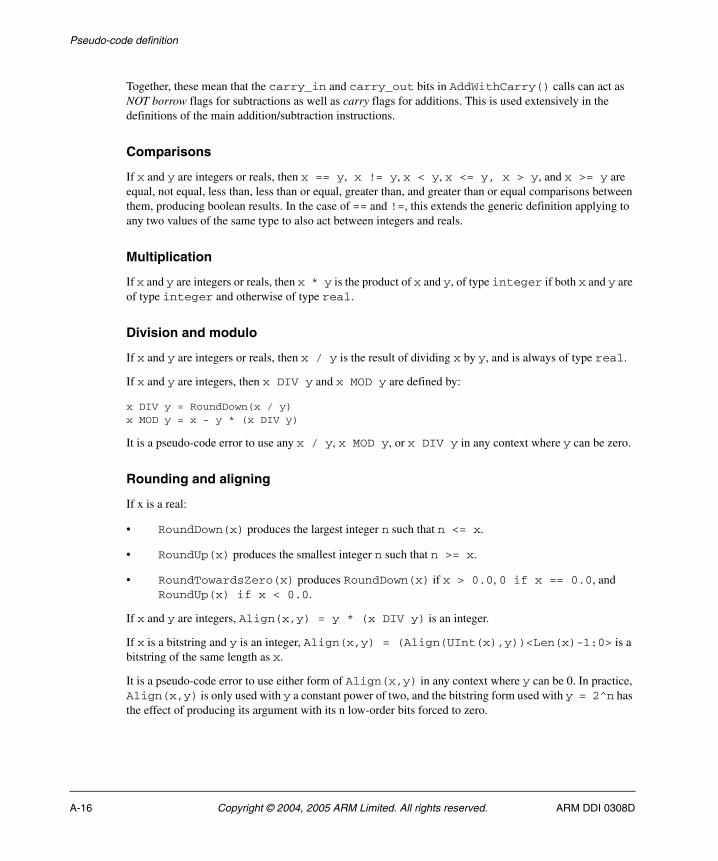
Pseudo-code definition
Together, these mean that the carry_in and carry_out bits in AddWithCarry() calls can act as NOT borrow flags for subtractions as well as carry flags for additions. This is used extensively in the definitions of the main addition/subtraction instructions.
Comparisons
If x and y are integers or reals, then x == y, x != y, x < y, x <= y, x > y, and x >= y are equal, not equal, less than, less than or equal, greater than, and greater than or equal comparisons between them, producing boolean results. In the case of == and !=, this extends the generic definition applying to any two values of the same type to also act between integers and reals.
Multiplication
If x and y are integers or reals, then x * y is the product of x and y, of type integer if both x and y are of type integer and otherwise of type real.
Division and modulo
If x and y are integers or reals, then x / y is the result of dividing x by y, and is always of type real.
If x and y are integers, then x DIV y and x MOD y are defined by:
x DIV y = RoundDown(x / y)x MOD y = x - y * (x DIV y)
It is a pseudo-code error to use any x / y, x MOD y, or x DIV y in any context where y can be zero.
Rounding and aligning
If x is a real:
• RoundDown(x) produces the largest integer n such that n <= x.
• RoundUp(x) produces the smallest integer n such that n >= x.
• RoundTowardsZero(x) produces RoundDown(x) if x > 0.0, 0 if x == 0.0, and RoundUp(x) if x < 0.0.
If x and y are integers, Align(x,y) = y * (x DIV y) is an integer.
If x is a bitstring and y is an integer, Align(x,y) = (Align(UInt(x),y))<Len(x)-1:0> is a bitstring of the same length as x.
It is a pseudo-code error to use either form of Align(x,y) in any context where y can be 0. In practice, Align(x,y) is only used with y a constant power of two, and the bitstring form used with y = 2^n has the effect of producing its argument with its n low-order bits forced to zero.
A-16 Copyright © 2004, 2005 ARM Limited. All rights reserved. ARM DDI 0308D
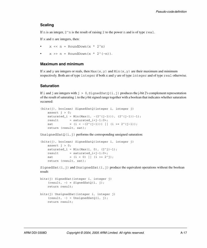
Pseudo-code definition
Scaling
If n is an integer, 2^n is the result of raising 2 to the power n and is of type real.
If x and n are integers, then:
• x << n = RoundDown(x * 2^n)
• x >> n = RoundDown(x * 2^(-n)).
Maximum and minimum
If x and y are integers or reals, then Max(x,y) and Min(x,y) are their maximum and minimum respectively. Both are of type integer if both x and y are of type integer and of type real otherwise.
Saturation
If i and j are integers with j > 0, SignedSatQ(i,j) produces the j-bit 2's complement representation of the result of saturating i to the j-bit signed range together with a boolean that indicates whether saturation occurred:
(bits(j), boolean) SignedSatQ(integer i, integer j) assert j > 0; saturated_i = Min(Max(i, -(2^(j-1))), (2^(j-1))-1); result = saturated_i<j-1:0>; sat = (i < -(2^(j-1))) || (i >= 2^(j-1)); return (result, sat);
UnsignedSatQ(i,j) performs the corresponding unsigned saturation:
(bits(j), boolean) SignedSatQ(integer i, integer j) assert j > 0; saturated_i = Min(Max(i, 0), (2^j)-1); result = saturated_i<j-1:0>; sat = (i < 0) || (i >= 2^j); return (result, sat);
SignedSat(i,j) and UnsignedSat(i,j) produce the equivalent operations without the boolean result:
bits(j) SignedSat(integer i, integer j) (result, -) = SignedSatQ(i, j); return result;
bits(j) UnsignedSat(integer i, integer j) (result, -) = UnsignedSatQ(i, j); return result;
ARM DDI 0308D Copyright © 2004, 2005 ARM Limited. All rights reserved. A-17
Pseudo-code definition
A.5 Statements and program structure
This section describes the control statements used in the pseudo-code.
A.5.1 Simple statements
The following simple statements must all be terminated with a semicolon, as shown.
Assignments
An assignment statement takes the form:
<assignable_expression> = <expression>;
Procedure calls
A procedure call takes the form:
<procedure_name>(<arguments>);
Return statements
A procedure return takes the form:
return;
and a function return takes the form:
return <expression>;
where <expression> is of the type the function prototype line declared.
UNDEFINED
The statement:
UNDEFINED;
indicates a special case that replaces the behavior defined by the current pseudo-code (apart from behavior required to determine that the special case applies). The replacement behavior is that the Undefined Instruction exception is taken.
UNPREDICTABLE
The statement:
UNPREDICTABLE;
A-18 Copyright © 2004, 2005 ARM Limited. All rights reserved. ARM DDI 0308D

Pseudo-code definition
indicates a special case that replaces the behavior defined by the current pseudo-code (apart from behavior required to determine that the special case applies). The replacement behavior is not architecturally defined and must not be relied upon by software. It must not constitute a security hole or halt or hang the system, and must not be promoted as providing any useful information to software.
SEE...
The statement:
SEE <reference>;
indicates a special case that replaces the behavior defined by the current pseudo-code (apart from behavior required to determine that the special case applies). The replacement behavior is that nothing occurs as a result of the current pseudo-code because some other piece of pseudo-code defines the required behavior. The <reference> indicates where that other pseudo-code can be found.
A.5.2 Compound statements
Indentation is normally used to indicate structure in compound statements. The statements contained in structures such as if ... then ... else ... or procedure and function definitions are indented more deeply than the statement itself, and their end is indicated by returning to the original indentation level or less.
Indentation is normally done by four spaces for each level.
if ... then ... else ...
A multi-line if ... then ... else ... structure takes the form:
if <boolean_expression> then <statement 1> <statement 2> ... <statement n>else <statement A> <statement B> ... <statement Z>
The else and its following statements are optional.
Abbreviated one-line forms can be used when there is just one simple statement in the then part and (if present) the else part, as follows:
if <boolean_expression> then <statement 1>
if <boolean_expression> then <statement 1> else <statement A>
ARM DDI 0308D Copyright © 2004, 2005 ARM Limited. All rights reserved. A-19
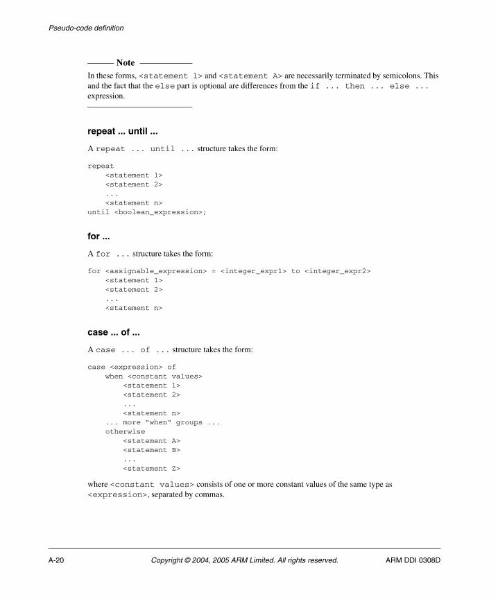
Pseudo-code definition
Note In these forms, <statement 1> and <statement A> are necessarily terminated by semicolons. This and the fact that the else part is optional are differences from the if ... then ... else ... expression.
repeat ... until ...
A repeat ... until ... structure takes the form:
repeat <statement 1> <statement 2> ... <statement n>until <boolean_expression>;
for ...
A for ... structure takes the form:
for <assignable_expression> = <integer_expr1> to <integer_expr2> <statement 1> <statement 2> ... <statement n>
case ... of ...
A case ... of ... structure takes the form:
case <expression> of when <constant values> <statement 1> <statement 2> ... <statement n> ... more "when" groups ... otherwise <statement A> <statement B> ... <statement Z>
where <constant values> consists of one or more constant values of the same type as <expression>, separated by commas.
A-20 Copyright © 2004, 2005 ARM Limited. All rights reserved. ARM DDI 0308D
Pseudo-code definition
Procedure and function definitions
A procedure definition takes the form:
<procedure name>(<argument prototypes>) <statement 1> <statement 2> ... <statement n>
where the <argument prototypes> consists of zero or more argument definitions, separated by commas. Each argument definition consists of a type name followed by the name of the argument.
Note This first prototype line is not terminated by a semicolon. This helps to distinguish it from a procedure call.
A function definition is similar, but also declares the return type of the function:
<return type> <function name>(<argument prototypes>) <statement 1> <statement 2> ... <statement n>
A.5.3 Comments
Two styles of pseudo-code comment exist:
• // starts a comment that is terminated by the end of the line.
• /* starts a comment that is terminated by */.
ARM DDI 0308D Copyright © 2004, 2005 ARM Limited. All rights reserved. A-21
Pseudo-code definition
A.6 Helper procedures and functions
The functions described in this section are not part of the pseudo-code specification. They are helper procedures and functions used by pseudo-code to perform useful architecture-specific jobs. Each has a brief description and a pseudo-code prototype. Some have had a pseudo-code definition added.
A.6.1 ALUWritePC()
This procedure writes a value to the PC with the correct semantics for such a write by data-processing instructions. That is, it has BX-like interworking behavior if performed by an ARM instruction in ARMv7 or above, and only a change to the PC otherwise.
ALUWritePC(bits(32) value)
A.6.2 ArchVersion()
This function returns the major version number of the architecture.
integer ArchVersion()
A.6.3 ARMExpandImm(), ARMExpandImmWithC()
These functions do the standard expansion of the 12 bits specifying an ARM data-processing immediate to its 32-bit value. The WithC version also produces a carry out bit.
// ARMExpandImm()// --------------bits(32) ARMExpandImm(bits(12) imm12)(imm32, -) = ARMExpandImmWithC(imm12);return imm12;// ARMExpandImmWithC()// -------------------(bits(32), bit) ARMExpandImmWithC(bits(12) imm12)if imm12<11:8> == '0000' then imm32 = ZeroExtend(imm12<7:0>, 32); carry_out = APSR.C;else unrotated_value = ZeroExtend(imm12<7:0>, 32); (imm32, carry_out) = ROR_C(unrotated_value, 2*UInt(imm12<11:8>));return (imm32, carry_out);
A.6.4 BadReg()
This function performs the check for the register numbers 13 and 15 that are disallowed for many Thumb register specifiers.
boolean BadReg(integer n)return n == 13 || n == 15;
A-22 Copyright © 2004, 2005 ARM Limited. All rights reserved. ARM DDI 0308D
Pseudo-code definition
A.6.5 BigEndian()
This function returns TRUE if load/store operations are currently big-endian, and FALSE if they are little-endian.
boolean BigEndian()
A.6.6 BranchWritePC()
This procedure writes a value to the PC with the correct semantics for such writes by simple branches - that is, just a change to the PC in all circumstances.
BranchWritePC(bits(32) value)
A.6.7 BreakPoint()
This procedure causes a debug breakpoint to occur.
A.6.8 BXWritePC()
This procedure writes a value to the PC with the correct semantics for such writes by interworking instructions. That is, with BX-like interworking behavior in all circumstances.
BXWritePC(bits(32) value)
A.6.9 CallSecureMonitor()
This procedure calls the Secure Monitor.
A.6.10 CallSupervisor()
This procedure calls the Supervisor.
A.6.11 ClearEventRegister()
This procedure clears the event register on the current processor. See EventRegistered() on page A-26 for details of the event register.
A.6.12 ClearExclusiveMonitors()
This procedure clears the monitors used by the load/store exclusive instructions.
ARM DDI 0308D Copyright © 2004, 2005 ARM Limited. All rights reserved. A-23
Pseudo-code definition
A.6.13 ConditionPassed()
This function performs the condition test for an instruction, based on:
• the 4-bit cond field of the instruction for ARM instructions and for the two Thumb conditional branch encodings (encodings T1 andT3 of the B instruction)
• the current values of the CPSR.IT[7:0] bits for other Thumb instructions.
boolean ConditionPassed()
A.6.14 Coproc_Accepted()
This function determines whether a coprocessor accepts an instruction.
boolean Coproc_Accepted(integer cp_num, bits(32) instr)
A.6.15 Coproc_DoneLoading()
This function determines for an LDC instruction whether enough words have been loaded.
boolean Coproc_DoneLoading(integer cp_num, bits(32) instr)
A.6.16 Coproc_DoneStoring()
This function determines for an STC instruction whether enough words have been stored.
boolean Coproc_DoneStoring(integer cp_num, bits(32) instr)
A.6.17 Coproc_GetOneWord()
This function obtains the word for an MRC instruction from the coprocessor.
bits(32) Coproc_GetOneWord(integer cp_num, bits(32) instr)
A.6.18 Coproc_GetTwoWords()
This function obtains the two words for an MRRC instruction from the coprocessor.
(bits(32), bits(32)) Coproc_GetTwoWords(integer cp_num, bits(32) instr)
A.6.19 Coproc_GetWordToStore()
This function obtains the next word to store for an STC instruction from the coprocessor
bits(32) Coproc_GetWordToStore(integer cp_num, bits(32) instr)
A-24 Copyright © 2004, 2005 ARM Limited. All rights reserved. ARM DDI 0308D
Pseudo-code definition
A.6.20 Coproc_InternalOperation()
This procedure instructs a coprocessor to perform the internal operation requested by a CDP instruction.
Coproc_InternalOperation(integer cp_num, bits(32) instr)
A.6.21 Coproc_SendLoadedWord()
This procedure sends a loaded word for an LDC instruction to the coprocessor.
Coproc_SendLoadedWord(bits(32) word, integer cp_num, bits(32) instr)
A.6.22 Coproc_SendOneWord()
This procedure sends the word for an MCR instruction to the coprocessor.
Coproc_SendOneWord(bits(32) word, integer cp_num, bits(32) instr)
A.6.23 Coproc_SendTwoWords()
This procedure sends the two words for an MCRR instruction to the coprocessor.
Coproc_SendTwoWords(bits(32) word1, bits(32) word2, integer cp_num, bits(32) instr)
A.6.24 CurrentInstrSet()
This function returns an enumeration value that identifies the current instruction set.
enumeration InstrSet (InstrSetARM, InstrSet_Thumb, InstrSet_Java, InstrSet_ThumbEE);InstrSet CurrentInstrSet()
A.6.25 CurrentModeHasSPSR()
This function determines whether the current processor mode has an SPSR. All modes except User or System mode have an SPSR.
boolean CurrentModeHasSPSR()
A.6.26 CurrentModeIsPrivileged()
This function determines whether the current processor mode is privileged. All modes except User mode are privileged.
boolean CurrentModeHasSPSR()
ARM DDI 0308D Copyright © 2004, 2005 ARM Limited. All rights reserved. A-25
Pseudo-code definition
A.6.27 DataMemoryBarrier()
This procedure produces a Data Memory Barrier.
DataMemoryBarrier(bits(4) option)
A.6.28 DataSynchronizationBarrier()
This procedure produces a Data Synchronization Barrier.
DataSynchronizationBarrier(bits(4) option)
A.6.29 DecodeImmShift(), DecodeRegShift()
These functions perform the standard 2-bit type, 5-bit amount and 2-bit type decodes for immediate and register shifts respectively. See Shift operations on page 4-11.
A.6.30 EventRegistered()
This function returns TRUE if the event register on the current processor is set and FALSE if it is clear. The event register is set as a result of any of the following events:
• an IRQ interrupt, unless masked by the CPSR I-bit
• an FIQ interrupt, unless masked by the CPSR F-bit
• an Imprecise Data abort, unless masked by the CPSR A-bit
• a Debug Entry request, if Debug is enabled
• an event sent by any processor in the multi-processor system as a result of that processor executing a Hint_SendEvent()
• an exception return
• implementation-specific reasons, that might be IMPLEMENTATION DEFINED but also might occur arbitrarily.
The state of the event register is UNKNOWN at Reset.
A.6.31 EncodingSpecificOperations()
This procedure invokes the encoding-specific pseudo-code for an instruction encoding and performs other encoding-specific operations, as defined in the pseudocode beneath the encoding diagram for the particular encoding.
A.6.32 ExclusiveMonitorsPass()
This function determines whether a store exclusive instruction is successful. A store exclusive is successful if it still has possession of the exclusive monitors.
A-26 Copyright © 2004, 2005 ARM Limited. All rights reserved. ARM DDI 0308D
Pseudo-code definition
boolean ExclusiveMonitorsPass(bits(32) address, integer size)
A.6.33 Hint_Debug()
This procedure supplies a hint to the debug system.
Hint_Debug(bits(4) option)
A.6.34 Hint_PreloadData()
This procedure performs a preload data hint.
Hint_PreloadData(bits(32) address)
A.6.35 Hint_PreloadInstr()
This procedure performs a preload instructions hint.
Hint_PreloadInstr(bits(32) address)
A.6.36 Hint_SendEvent()
This procedure performs a send event hint.
A.6.37 Hint_Yield()
This procedure performs a Yield hint.
A.6.38 InITBlock()
This function returns TRUE if execution is currently in an IT block and FALSE otherwise.
boolean InITBlock()
A.6.39 InstructionSynchronizationBarrier()
This procedure produces an Instruction Synchronization Barrier.
InstructionSynchronizationBarrier(bits(4) option)
A.6.40 IntegerZeroDivideTrappingEnabled()
This function returns TRUE if the trapping of divisions by zero in the integer division instructions SDIV and UDIV is enabled, and FALSE otherwise.
In the R profile, this is controlled by the DZ bit (bit[19]) of CP15 register 1. TRUE is returned if the bit is 1 and FALSE if it is 0. This function is never called in the A profile.
ARM DDI 0308D Copyright © 2004, 2005 ARM Limited. All rights reserved. A-27
Pseudo-code definition
A.6.41 JazelleAcceptsExecution()
This function indicates whether Jazelle hardware will take over execution when a BXJ instruction is executed.
boolean JazelleAcceptsExecution()
A.6.42 LastInITBlock()
This function returns TRUE if the current instruction is the last instruction in an IT block, and FALSE otherwise.
A.6.43 LoadWritePC()
This procedure writes a value to the PC with the correct semantics for such writes by load instructions. That is, with BX-like interworking behavior in ARMv5 and above, and just a change to the PC in ARMv4T.
LoadWritePC(bits(32) value)
A.6.44 MemA[]
This array-like function performs a memory access that is required to be aligned, using the current privilege level.
bits(8*size) MemA[bits(32) address, integer size]MemA[bits(32) address, integer size] = bits(8*size) value
A.6.45 MemAA[]
This array-like function performs a memory access that is required to be aligned and atomic, using the current privilege level.
bits(8*size) MemAA[bits(32) address, integer size]MemAA[bits(32) address, integer size] = bits(8*size) value
A.6.46 MemU[]
This array-like function performs a memory access that is allowed to be unaligned, using the current privilege level.
bits(8*size) MemU[bits(32) address, integer size]MemU[bits(32) address, integer size] = bits(8*size) value
A.6.47 MemU_unpriv[]
This array-like function performs a memory access that is allowed to be unaligned, as an unprivileged access regardless of the current privilege level.
A-28 Copyright © 2004, 2005 ARM Limited. All rights reserved. ARM DDI 0308D
Pseudo-code definition
bits(8*size) MemU_unpriv[bits(32) address, integer size]MemU_unpriv[bits(32) address, integer size] = bits(8*size) value
A.6.48 PCStoreValue()
This function returns the value to be stored by an instruction that stores the PC. It is IMPLEMENTATION DEFINED whether this is the address of the instruction plus 8 or the address of the instruction plus 12. This only applies to ARM instructions, because no Thumb instructions store the PC.
bits(32) PCStoreValue()
A.6.49 R[]
This array-like function reads or writes a register. Reading register 13, 14, or 15 reads the SP, LR or PC respectively and writing register 13 or 14 writes the SP or LR respectively.
bits(32) R[integer n]R[integer n] = bits(32) value;
A.6.50 RaiseCoprocessorException()
This procedure raises the appropriate exception for a rejected coprocessor instruction.
In the A and R profiles, this is an Undefined Instruction exception.
A.6.51 RaiseIntegerZeroDivide()
This procedure raises the appropriate exception for a division by zero in the integer division instructions SDIV and UDIV.
In the R profile, this is an Undefined Instruction exception. This exception is never raised in the A profile.
A.6.52 Rmode[]
This array-like function reads or write a register belonging to a specified processor mode, and is otherwise identical to R[].
bits(32) R[integer n, integer mode]R[integer n, integer mode] = bits(32) value;
A.6.53 Select_InstrSet()
This procedure selects a new instruction set to execute.
enumeration InstrSet (InstrSetARM, InstrSet_Thumb, InstrSet_Java, InstrSet_ThumbEE);Select_InstrSet(InstrSet iset)
ARM DDI 0308D Copyright © 2004, 2005 ARM Limited. All rights reserved. A-29
Pseudo-code definition
A.6.54 SetEndianness()
This procedure sets the current endianness for load/store instructions.
enumeration Endian (Endian_Little, Endian_Big);SetEndianness(Endian new)
A.6.55 SetExclusiveMonitors()
This procedure sets the exclusive monitors for a load exclusive instruction.
SetExclusiveMonitors(bits(32) address, integer size)
A.6.56 Shift(), Shift_C()
These functions perform standard ARM shifts on values, returning a result value and in the case of Shift_C(), a carry out bit. See Shift operations on page 4-11.
A.6.57 StartITBlock()
This procedure starts an IT block with specified first condition and mask values.
StartITBlock(bits(4) firstcond, bits(4) mask)
A.6.58 SwitchToJazelleExecution()
This procedure passes control of execution to Jazelle hardware (for a BXJ instruction).
A.6.59 ThisInstr()
This function returns the currently-executing instruction. It is only used on 32-bit instruction encodings at present.
bits(32) ThisInstr()
A.6.60 ThumbExpandImm(), ThumbExpandImmWithC()
These functions do the standard expansion of the 12 bits specifying an Thumb data-processing immediate to its 32-bit value. The WithC version also produces a carry out bit. See Operation on page 4-9.
A.6.61 WaitForEvent()
This procedure causes the processor to suspend execution until any processor in the multiprocessor system executes a SEV instruction, or any of the following occurs for the processor itself:
• an IRQ interrupt, unless masked by the CPSR I-bit
• an FIQ interrupt, unless masked by the CPSR F-bit
A-30 Copyright © 2004, 2005 ARM Limited. All rights reserved. ARM DDI 0308D
Pseudo-code definition
• an Imprecise Data abort, unless masked by the CPSR A-bit
• a Debug Entry request, if Debug is enabled
• implementation-specific reasons, that might be IMPLEMENTATION DEFINED but also might occur arbitrarily
• Reset.
It is IMPLEMENTATION DEFINED whether or not restarting execution after the period of suspension causes a ClearEventRegister() to occur.
A.6.62 WaitForInterrupt()
This procedure causes the processor to suspend execution until any of the following occurs for that processor:
• an IRQ interrupt, regardless of the CPSR I-bit
• an FIQ interrupt, regardless of the CPSR F-bit
• an Imprecise Data abort, regardless of the CPSR A-bit
• a Debug Entry request, if Debug is enabled
• implementation-specific reasons, that might be IMPLEMENTATION DEFINED but also might occur arbitrarily
• Reset.
A.6.63 WriteCPSRUnderMask()
This procedure performs the write CPSR actions for an MSR CPSR instruction in the ARMv7-A or ARMv7-R profiles.
WriteCPSRUnderMask(bits(32) value, bits(4) mask
A.6.64 WriteSPSRUnderMask()
This procedure performs the write SPSR actions for an MSR SPSR instruction in the ARMv7-A or ARMv7-R profiles.
WriteSPSRUnderMask(bits(32) value, bits(4) mask
ARM DDI 0308D Copyright © 2004, 2005 ARM Limited. All rights reserved. A-31

Pseudo-code definition
A-32 Copyright © 2004, 2005 ARM Limited. All rights reserved. ARM DDI 0308D
Glossary
APSR See Application Program Status Register.
Application Program Status RegisterThe register containing those bits that deliver status information about the results of instructions. In this manual, synonymous with the CPSR, but only the N, Z, C, V, Q and GE[3:0] bits of the CPSR are accessed using the APSR name.
IMPLEMENTATION DEFINEDMeans that the behavior is not architecturally defined, but must be defined and documented by individual implementations.
IT block An IT block is a block of up to four instructions following an If-Then (IT) instruction. Each instruction in the block is conditional. The conditions for the instructions are either all the same, or some can be the inverse of others. See IT on page 4-92 for additional information.
Memory hintA memory hint instruction allows you to provide advance information to memory systems about future memory accesses, without actually loading or storing any data. PLD and PLI are the only memory hint instructions currently provided.
Single Instruction, Multiple Data (SIMD)Single Instruction, Multiple Data (SIMD) instructions perform similar operations on four 8-bit, or two 16-bit, data items held in 32-bit registers. See SIMD add and subtract on page 3-21 for additional information.
UAL See Unified Assembler Language.
ARM DDI 0308D Copyright © 2004, 2005 ARM Limited. All rights reserved. Glossary-1
Glossary
UNDEFINEDAn attempt to execute an UNDEFINED instruction causes an Undefined Instruction exception.
Unified Assembler LanguageThe new assembler language used in this document. See Unified Assembler Language on page ix for details.
UNPREDICTABLEThe result of an UNPREDICTABLE instruction cannot be relied upon. UNPREDICTABLE instructions or results must not represent security holes. UNPREDICTABLE instructions must not halt or hang the processor, or any parts of the system.
Glossary-2 Copyright © 2004, 2005 ARM Limited. All rights reserved. ARM DDI 0308D