Embed Size (px)
Citation preview
Universität Dortmund
ARM Cortex-M3/M4 Instruction Set
& Architecture
Universität Dortmund
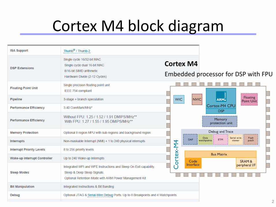
Cortex M4 block diagram
2
Cortex M4
Embedded processor for DSP with FPU
Universität Dortmund
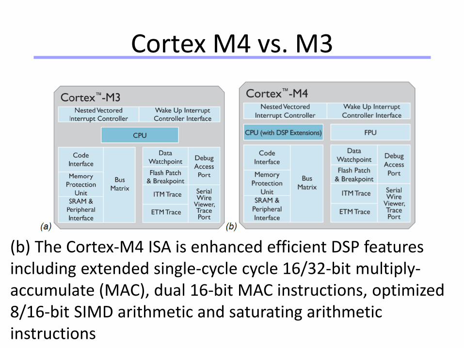
Cortex M4 vs. M3
(b) The Cortex-M4 ISA is enhanced efficient DSP features including extended single-cycle cycle 16/32-bit multiply-accumulate (MAC), dual 16-bit MAC instructions, optimized 8/16-bit SIMD arithmetic and saturating arithmetic instructions
Universität Dortmund
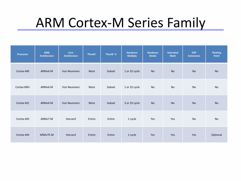
ARM Cortex-M Series Family
Processor ARM
ArchitectureCore
ArchitectureThumb® Thumb®-2
HardwareMultiply
HardwareDivide
SaturatedMath
DSPExtensions
FloatingPoint
Cortex-M0 ARMv6-M Von Neumann Most Subset 1 or 32 cycle No No No No
Cortex-M0+ ARMv6-M Von Neumann Most Subset 1 or 32 cycle No No No No
Cortex-M1 ARMv6-M Von Neumann Most Subset 3 or 33 cycle No No No No
Cortex-M3 ARMv7-M Harvard Entire Entire 1 cycle Yes Yes No No
Cortex-M4 ARMv7E-M Harvard Entire Entire 1 cycle Yes Yes Yes Optional
Universität Dortmund
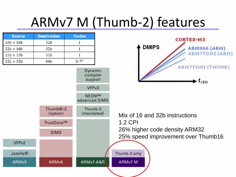
ARMv7 M (Thumb-2) features
Mix of 16 and 32b instructions
1.2 CPI
26% higher code density ARM32
25% speed improvement over Thumb16
Universität Dortmund
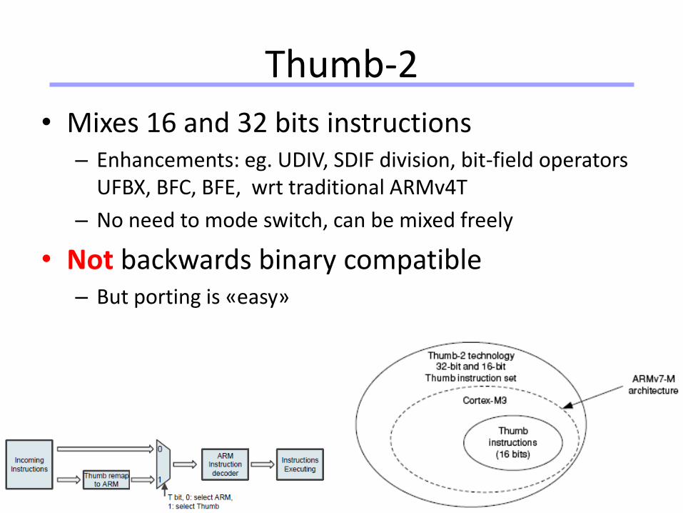
Thumb-2
• Mixes 16 and 32 bits instructions– Enhancements: eg. UDIV, SDIF division, bit-field operators
UFBX, BFC, BFE, wrt traditional ARMv4T
– No need to mode switch, can be mixed freely
• Not backwards binary compatible– But porting is «easy»
Universität Dortmund
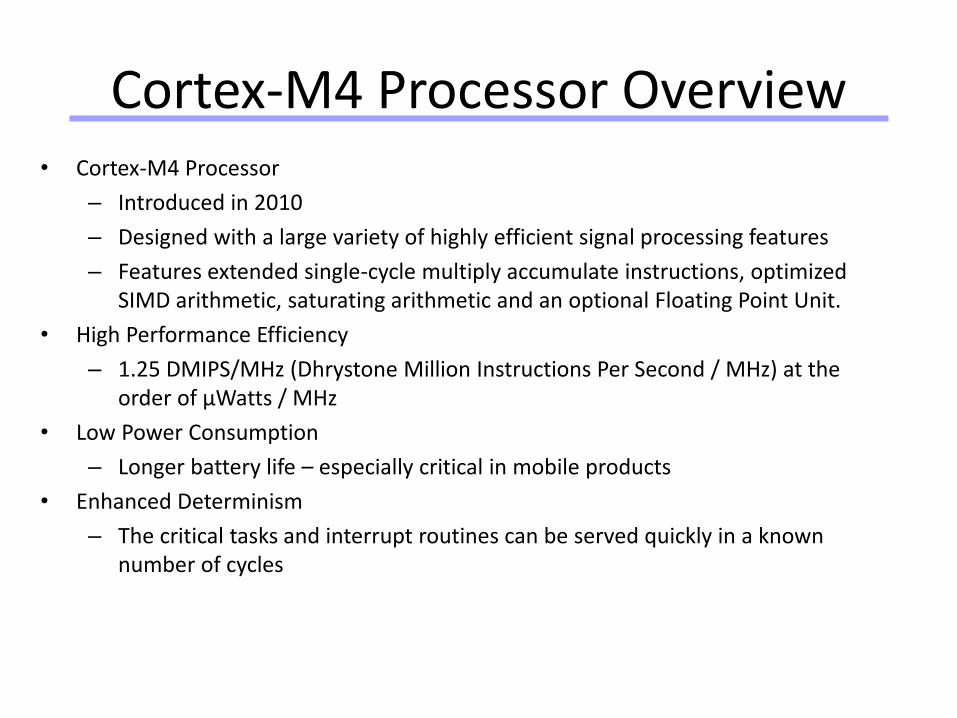
Cortex-M4 Processor Overview• Cortex-M4 Processor
– Introduced in 2010
– Designed with a large variety of highly efficient signal processing features
– Features extended single-cycle multiply accumulate instructions, optimized SIMD arithmetic, saturating arithmetic and an optional Floating Point Unit.
• High Performance Efficiency
– 1.25 DMIPS/MHz (Dhrystone Million Instructions Per Second / MHz) at the order of µWatts / MHz
• Low Power Consumption
– Longer battery life – especially critical in mobile products
• Enhanced Determinism
– The critical tasks and interrupt routines can be served quickly in a known number of cycles
Universität Dortmund
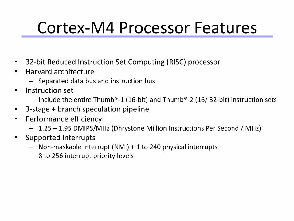
Cortex-M4 Processor Features
• 32-bit Reduced Instruction Set Computing (RISC) processor• Harvard architecture
– Separated data bus and instruction bus
• Instruction set– Include the entire Thumb®-1 (16-bit) and Thumb®-2 (16/ 32-bit) instruction sets
• 3-stage + branch speculation pipeline• Performance efficiency
– 1.25 – 1.95 DMIPS/MHz (Dhrystone Million Instructions Per Second / MHz)
• Supported Interrupts– Non-maskable Interrupt (NMI) + 1 to 240 physical interrupts– 8 to 256 interrupt priority levels
Universität Dortmund
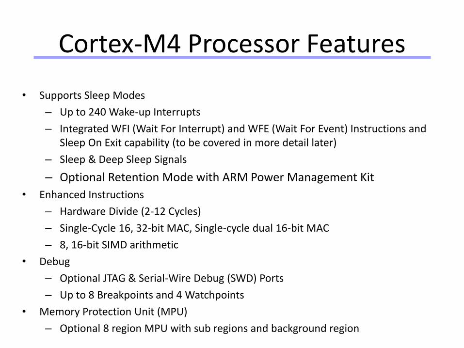
Cortex-M4 Processor Features
• Supports Sleep Modes
– Up to 240 Wake-up Interrupts
– Integrated WFI (Wait For Interrupt) and WFE (Wait For Event) Instructions and Sleep On Exit capability (to be covered in more detail later)
– Sleep & Deep Sleep Signals
– Optional Retention Mode with ARM Power Management Kit
• Enhanced Instructions
– Hardware Divide (2-12 Cycles)
– Single-Cycle 16, 32-bit MAC, Single-cycle dual 16-bit MAC
– 8, 16-bit SIMD arithmetic
• Debug
– Optional JTAG & Serial-Wire Debug (SWD) Ports
– Up to 8 Breakpoints and 4 Watchpoints
• Memory Protection Unit (MPU)
– Optional 8 region MPU with sub regions and background region
Universität Dortmund
Cortex-M4 Processor Features
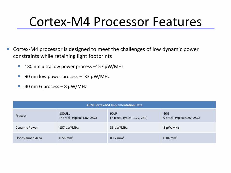
ARM Cortex-M4 Implementation Data
Process180ULL(7-track, typical 1.8v, 25C)
90LP(7-track, typical 1.2v, 25C)
40G9-track, typical 0.9v, 25C)
Dynamic Power 157 µW/MHz 33 µW/MHz 8 µW/MHz
Floorplanned Area 0.56 mm2 0.17 mm2 0.04 mm2
Cortex-M4 processor is designed to meet the challenges of low dynamic power constraints while retaining light footprints
180 nm ultra low power process –157 µW/MHz
90 nm low power process – 33 µW/MHz
40 nm G process – 8 µW/MHz
Universität Dortmund
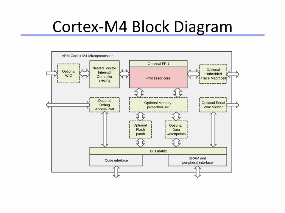
Cortex-M4 Block Diagram
Optional
WIC
Nested Vector
Interrupt
Controller
(NVIC)
Optional
Debug
Access Port
ARM Cortex-M4 Microprocessor
Optional Memory
protection unit
Bus matrix
Code interfaceSRAM and
peripheral interface
Optional FPU
Processor core
Optional
Embedded
Trace Macrocell
Optional Serial
Wire Viewer
Optional
Flash
patch
Optional
Data
watchpoints
Universität Dortmund
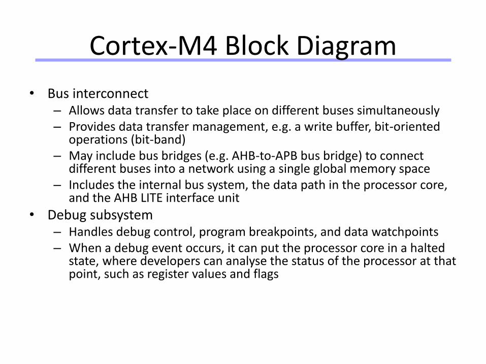
Cortex-M4 Block Diagram
• Bus interconnect– Allows data transfer to take place on different buses simultaneously– Provides data transfer management, e.g. a write buffer, bit-oriented
operations (bit-band)– May include bus bridges (e.g. AHB-to-APB bus bridge) to connect
different buses into a network using a single global memory space– Includes the internal bus system, the data path in the processor core,
and the AHB LITE interface unit
• Debug subsystem– Handles debug control, program breakpoints, and data watchpoints– When a debug event occurs, it can put the processor core in a halted
state, where developers can analyse the status of the processor at that point, such as register values and flags
Universität Dortmund
Cortex-M4 Block Diagram
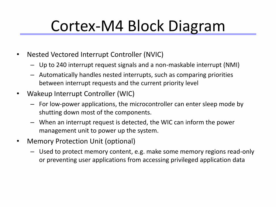
• Nested Vectored Interrupt Controller (NVIC)
– Up to 240 interrupt request signals and a non-maskable interrupt (NMI)
– Automatically handles nested interrupts, such as comparing priorities between interrupt requests and the current priority level
• Wakeup Interrupt Controller (WIC)
– For low-power applications, the microcontroller can enter sleep mode by shutting down most of the components.
– When an interrupt request is detected, the WIC can inform the power management unit to power up the system.
• Memory Protection Unit (optional)
– Used to protect memory content, e.g. make some memory regions read-only or preventing user applications from accessing privileged application data
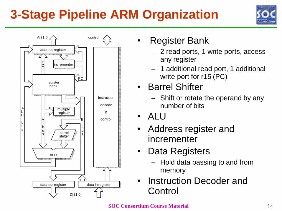
3-Stage Pipeline ARM Organization
• Register Bank– 2 read ports, 1 write ports, access
any register
– 1 additional read port, 1 additional write port for r15 (PC)
• Barrel Shifter– Shift or rotate the operand by any
number of bits
• ALU
• Address register and incrementer
• Data Registers– Hold data passing to and from
memory
• Instruction Decoder and Control
data out register
instruction
decode
&
control
incrementer
register bank
address register
barrel shifter
A[31:0]
D[31:0]
data in register
ALU
control
SOC Consortium Course Material 14
P C
PC
ALU
bus
A
bus
B
bus
multiply register
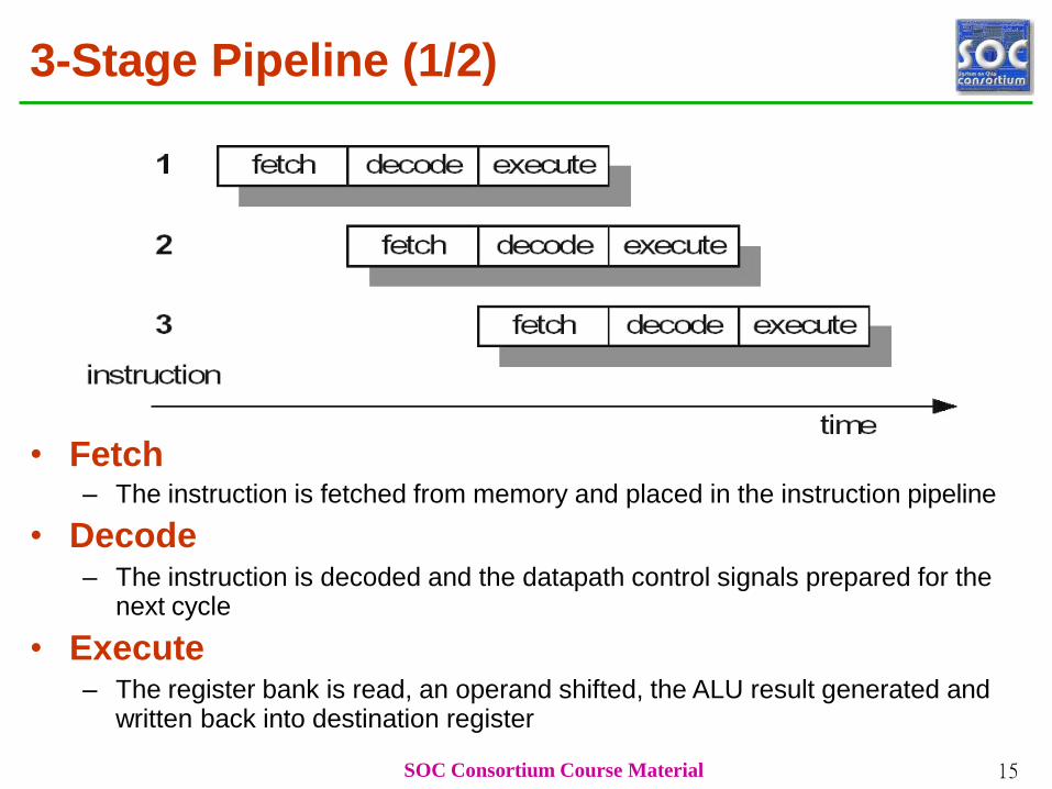
3-Stage Pipeline (1/2)
• Fetch– The instruction is fetched from memory and placed in the instruction pipeline
• Decode– The instruction is decoded and the datapath control signals prepared for the
next cycle
• Execute– The register bank is read, an operand shifted, the ALU result generated and
written back into destination register
SOC Consortium Course Material 15
3-Stage Pipeline (2/2)
SOC Consortium Course Material 16
• At any time slice, 3 different instructions may
occupy each of these stages, so the hardware in
each stage has to be capable of independent
operations
• When the processor is executing data processing
instructions , the latency = 3 cycles and the
throughput = 1 instruction/cycle
• There are exceptions: multiycle instructions and
branches
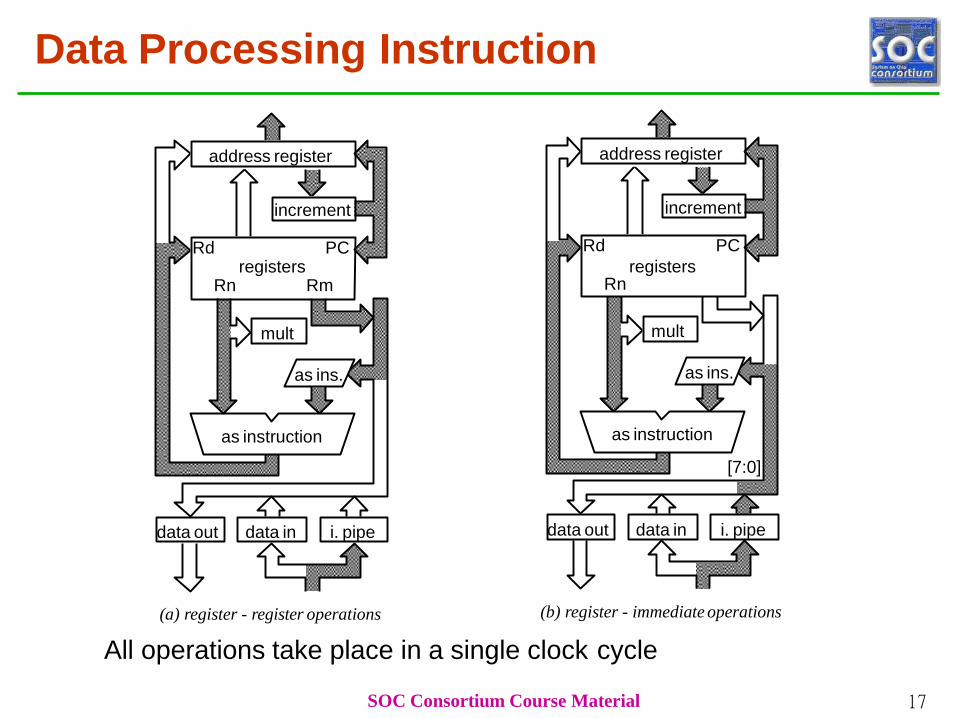
Data Processing Instruction
address register
increment
registers
Rd
Rn
PC
as ins.
as instruction
mult
data out data in i. pipe
[7:0]
(b) register - immediate operations
address register
increment
Rd PCregisters
Rn Rm
as ins.
as instruction
mult
data out
SOC Consortium Course Material 17
data in i. pipe
(a) register - register operations
All operations take place in a single clock cycle
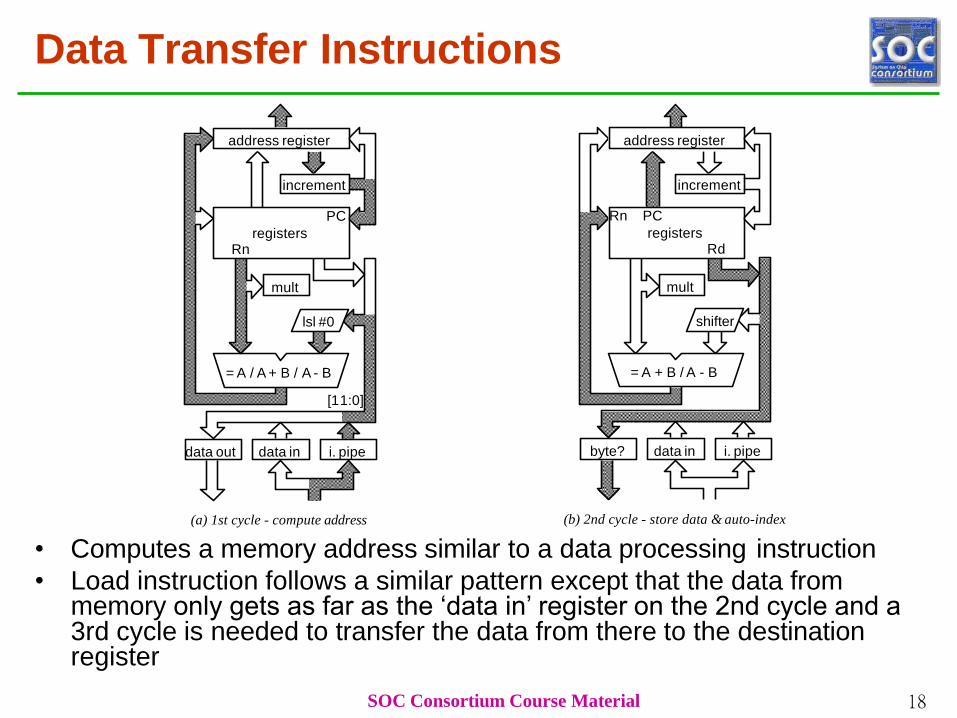
Data Transfer Instructions
address register
increment
PC
registersRn
lsl #0
mult
data out data in i. pipe
= A / A + B / A - B
[11:0]
address register
increment
shifter
= A + B / A - B
SOC Consortium Course Material 18
mult
Rn PC
registersRd
byte? data in i. pipe
(a) 1st cycle - compute address (b) 2nd cycle - store data & auto-index
• Computes a memory address similar to a data processing instruction
• Load instruction follows a similar pattern except that the data from memory only gets as far as the ‘data in’ register on the 2nd cycle and a 3rd cycle is needed to transfer the data from there to the destination register
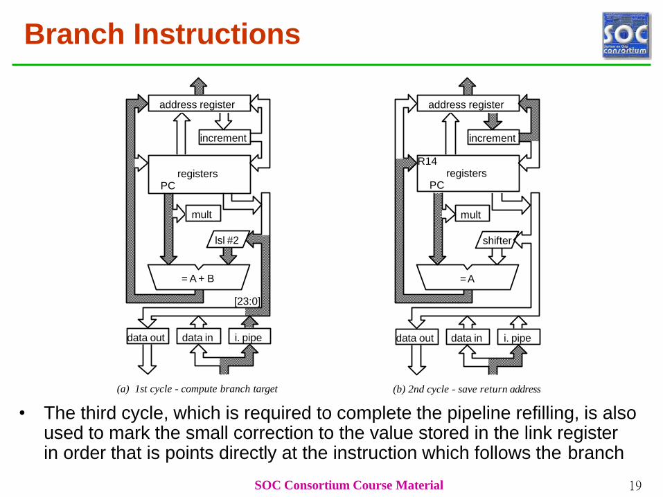
Branch Instructions
address register
increment
R14registers
PC
shifter
=A
mult
data out data in i. pipe
address register
increment
registersPC
lsl #2
= A + B
mult
SOC Consortium Course Material 19
data out data in i. pipe
[23:0]
(a) 1st cycle - compute branch target (b) 2nd cycle - save return address
• The third cycle, which is required to complete the pipeline refilling, is also used to mark the small correction to the value stored in the link register in order that is points directly at the instruction which follows the branch
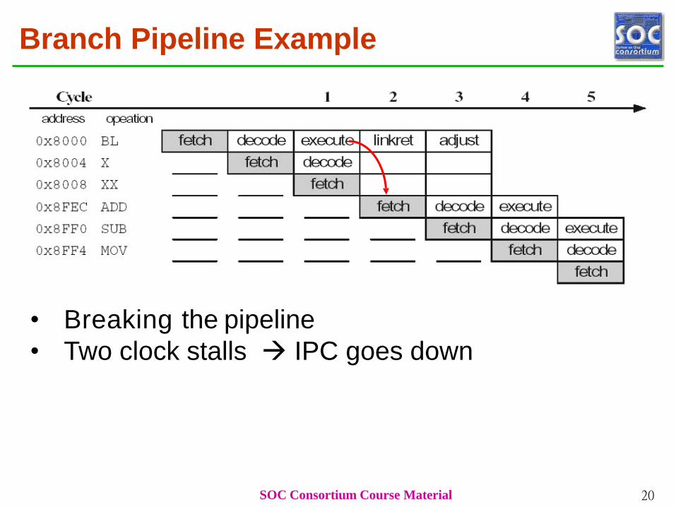
Branch Pipeline Example
• Breaking the pipeline
• Two clock stalls IPC goes down
SOC Consortium Course Material 20
Universität Dortmund
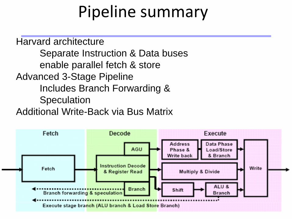
Pipeline summary
Harvard architecture
Separate Instruction & Data buses
enable parallel fetch & store
Advanced 3-Stage Pipeline
Includes Branch Forwarding &
Speculation
Additional Write-Back via Bus Matrix
Universität Dortmund
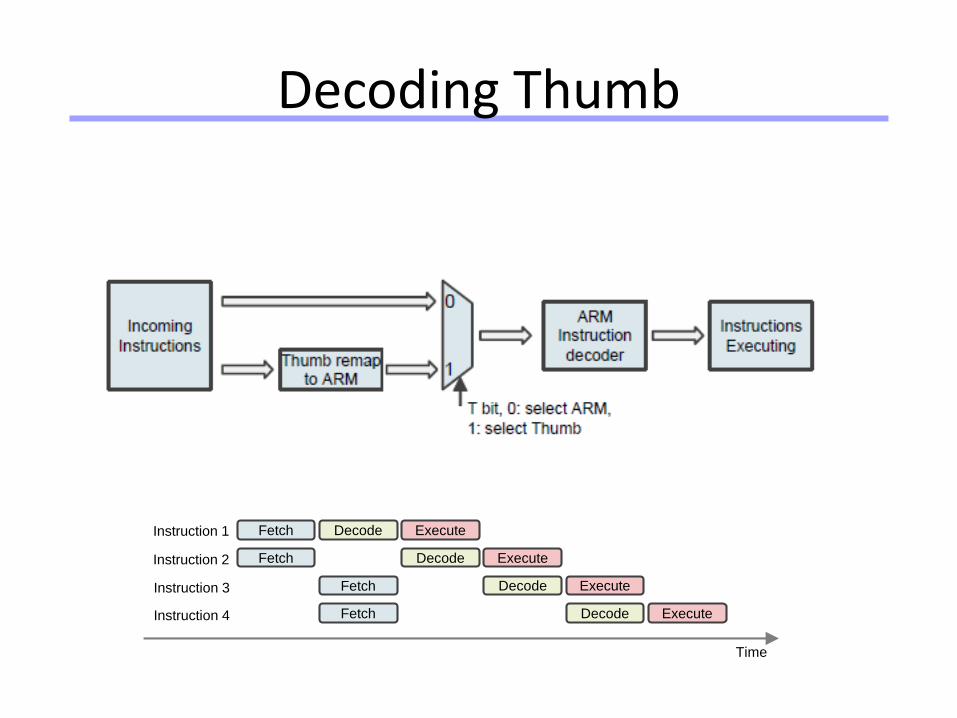
Decoding Thumb
Fetch Decode Execute
Fetch Decode Execute
Fetch Decode Execute
Instruction 1
Instruction 2
Instruction 3
Fetch Decode ExecuteInstruction 4
Time
Universität Dortmund
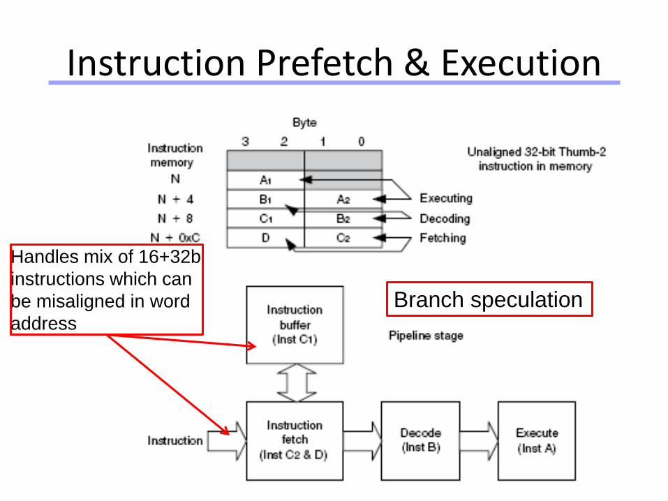
Instruction Prefetch & Execution
Handles mix of 16+32b
instructions which can
be misaligned in word
address
Branch speculation
Universität Dortmund
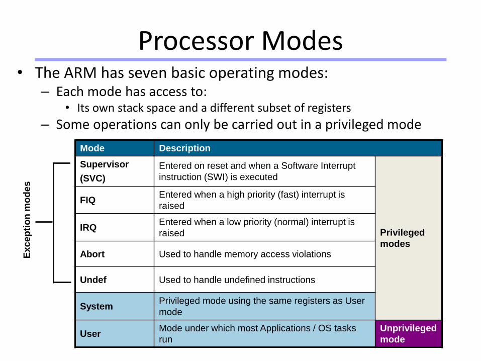
• The ARM has seven basic operating modes:– Each mode has access to:
• Its own stack space and a different subset of registers
– Some operations can only be carried out in a privileged mode
Processor Modes
Mode Description
Supervisor
(SVC)
Entered on reset and when a Software Interrupt
instruction (SWI) is executed
Privileged
modes
FIQEntered when a high priority (fast) interrupt is
raised
IRQEntered when a low priority (normal) interrupt is
raised
Abort Used to handle memory access violations
Undef Used to handle undefined instructions
SystemPrivileged mode using the same registers as User
mode
UserMode under which most Applications / OS tasks
run
Unprivileged
mode
Excep
tio
n m
od
es
Universität Dortmund
25
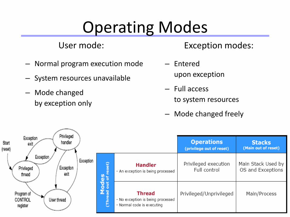
Operating ModesUser mode:
– Normal program execution mode
– System resources unavailable
– Mode changed
by exception only
Exception modes:
– Entered
upon exception
– Full access
to system resources
– Mode changed freely
Universität Dortmund
26
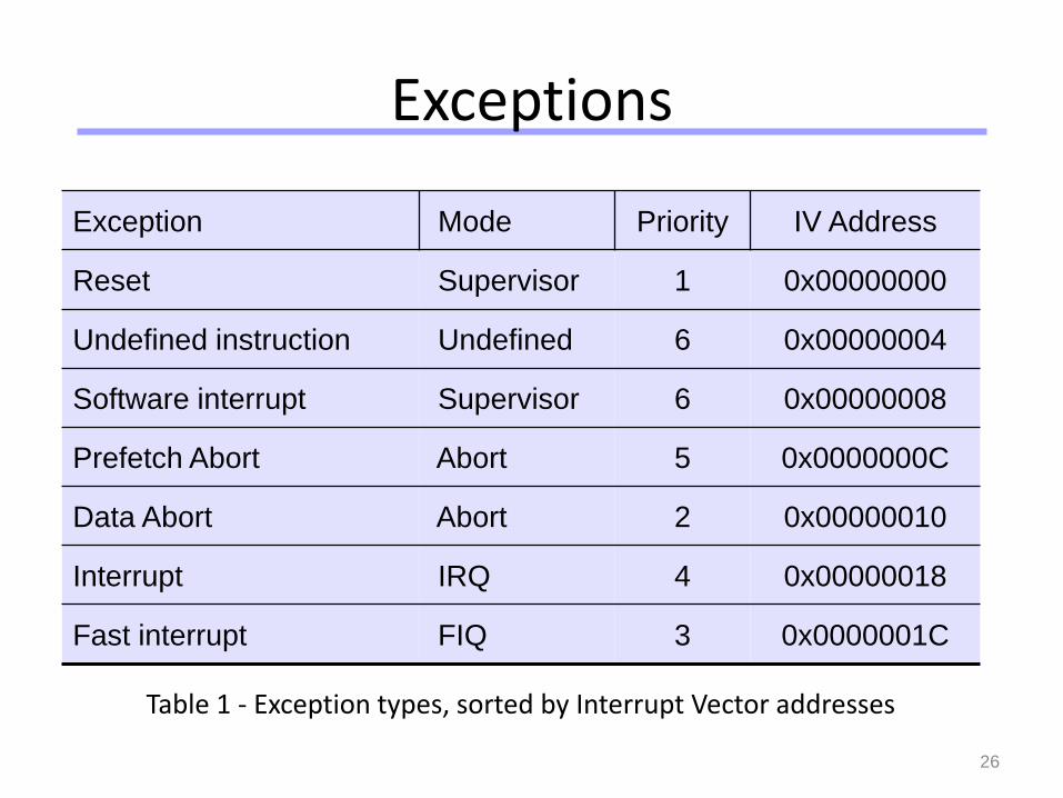
Exceptions
Table 1 - Exception types, sorted by Interrupt Vector addresses
Exception Mode Priority IV Address
Reset Supervisor 1 0x00000000
Undefined instruction Undefined 6 0x00000004
Software interrupt Supervisor 6 0x00000008
Prefetch Abort Abort 5 0x0000000C
Data Abort Abort 2 0x00000010
Interrupt IRQ 4 0x00000018
Fast interrupt FIQ 3 0x0000001C
Universität Dortmund
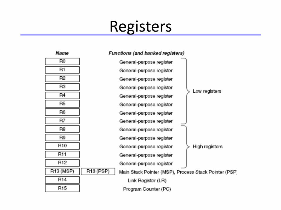
Registers
Universität Dortmund
28
ARM Registers
• 31 general-purpose 32-bit registers
• 16 visible, R0 – R15
• Others speed up the exception process
Universität Dortmund
29
ARM Registers (2)
• Special roles:
– Hardware
• R14 – Link Register (LR):
optionally holds return address
for branch instructions
• R15 – Program Counter (PC)
– Software
• R13 - Stack Pointer (SP)
Universität Dortmund
30
ARM Registers (3)
• Current Program Status Register (CPSR)
• Saved Program Status Register (SPSR)
• On exception, entering mod mode:
– (PC + 4) LR
– CPSR SPSR_mod
– PC IV address
– R13, R14 replaced by R13_mod, R14_mod
– In case of FIQ mode R7 – R12 also replaced
Universität Dortmund
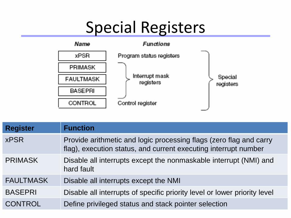
Special Registers
Register Function
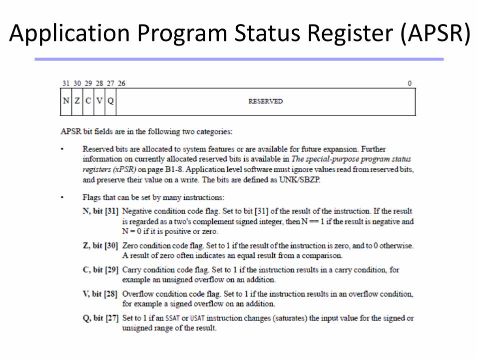
xPSR Provide arithmetic and logic processing flags (zero flag and carry
flag), execution status, and current executing interrupt number
PRIMASK Disable all interrupts except the nonmaskable interrupt (NMI) and
hard fault
FAULTMASK Disable all interrupts except the NMI
BASEPRI Disable all interrupts of specific priority level or lower priority level
CONTROL Define privileged status and stack pointer selection
Universität Dortmund
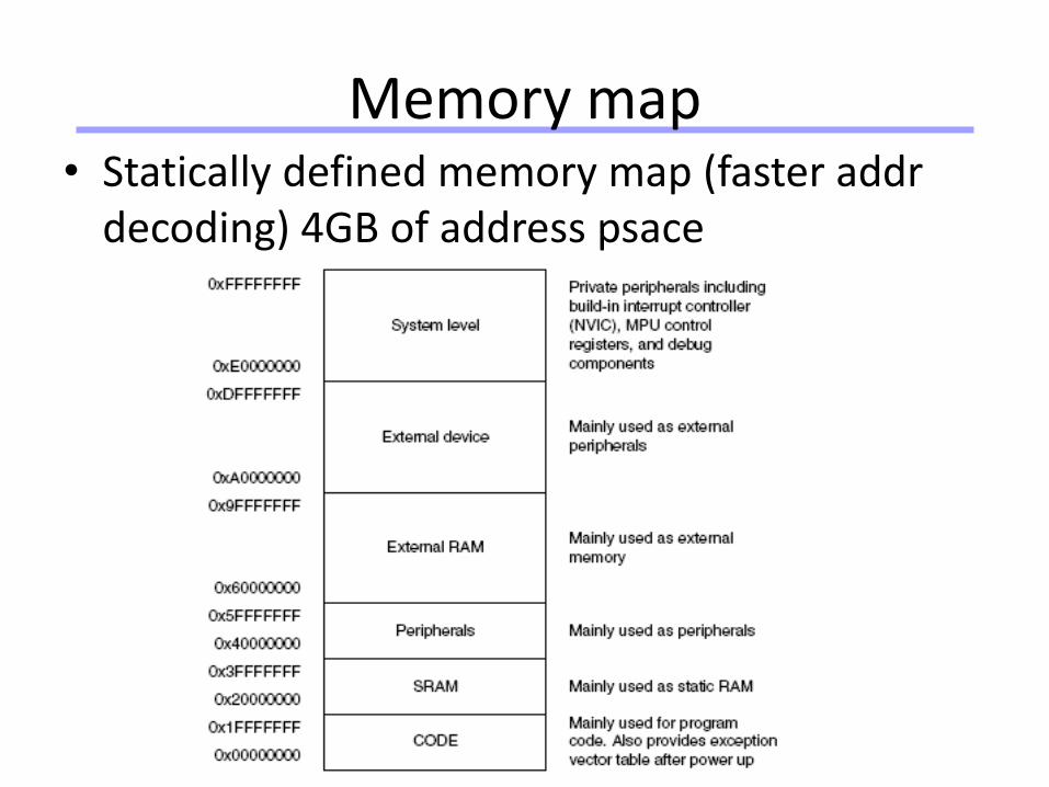
Memory map• Statically defined memory map (faster addr
decoding) 4GB of address psace
Universität Dortmund
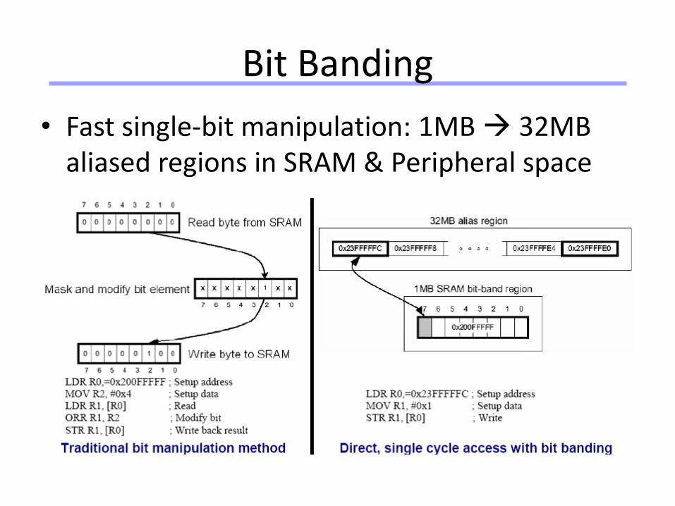
Bit Banding
• Fast single-bit manipulation: 1MB 32MB aliased regions in SRAM & Peripheral space
Universität Dortmund
Cortex M3/M4 Instruction Set
Universität Dortmund
35
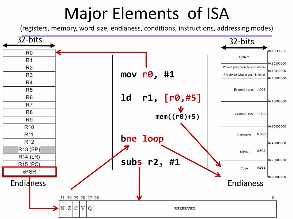
Major Elements of ISA(registers, memory, word size, endianess, conditions, instructions, addressing modes)
32-bits 32-bits
Endianess
mov r0, #1
ld r1, [r0,#5]
mem((r0)+5)
bne loop
subs r2, #1
Endianess
Universität Dortmund
Traditional ARM instructions
• Fixed length of 32 bits• Commonly take two or three operands• Process data held in registers• Shift & ALU operation in single clock cycle• Access memory with load and store instructions only
– Load/Store multiple register
• Can be extended to execute conditionally by adding the appropriate suffix
• Affect the CPSR status flags by adding the ‘S’ suffix to the instruction
Universität Dortmund
Thumb-2
• Original 16-bit Thumb instruction set
– a subset of the full ARM instructions
– performs similar functions to selective 32-bit ARM instructions but in 16-bit code size
• For ARM instructions that are not available
– more 16-bit Thumb instructions are needed to execute the same function compared to using ARM instructions
– but performance may be degraded
• Hence the introduction of the Thumb-2 instruction set
– enhances the 16-bit Thumb instructions with additional 32-bit instructions
• All ARMv7 chips support the Thumb-2 (& ARM) instruction set
– but Cortex-M3 supports only the 16-bit/32-bit Thumb-2 instruction set
Universität Dortmund
16bit Thumb-2
• reduce the number of bits used to identify the register– less number of registers can be used
• reduce the number of bits used for the immediate value– smaller number range
• remove options such as ‘S’– make it default for some instructions
• remove conditional fields (N, Z, V, C)• no conditional executions (except branch)• remove the optional shift (and no barrel shifter operation
– introduce dedicated shift instructions
• remove some of the instructions– more restricted coding
Some of the changes used to reduce the length of the
instructions from 32 bits to 16 bits:
Universität Dortmund
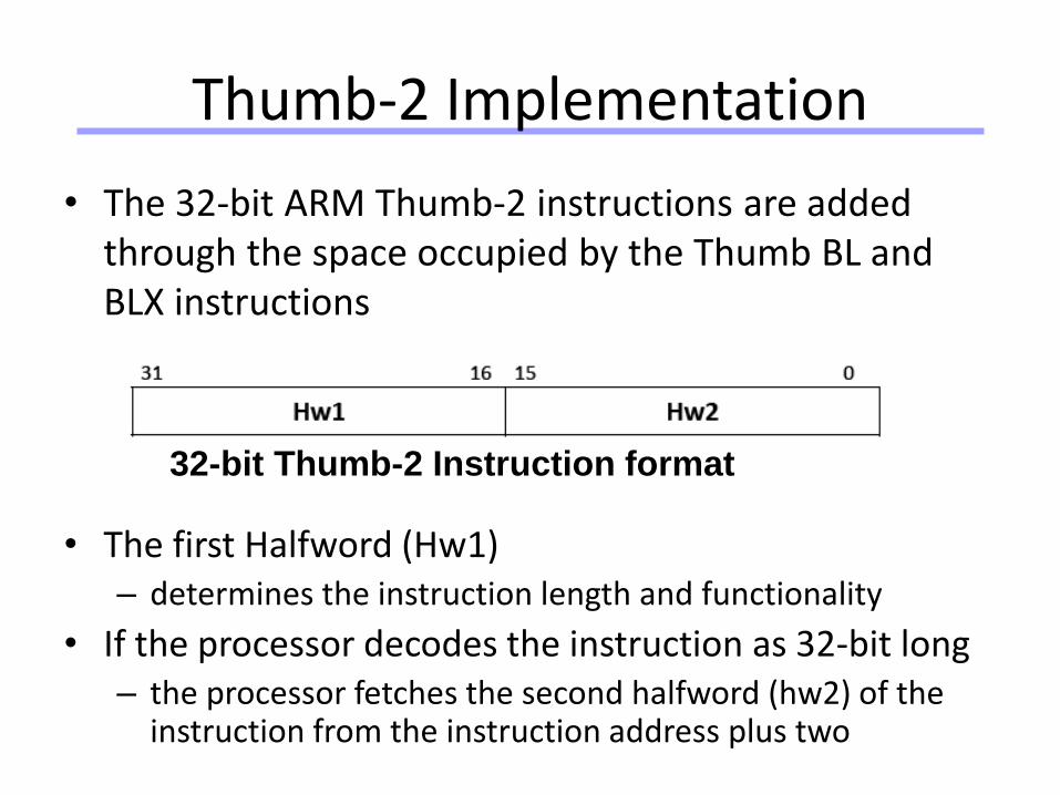
Thumb-2 Implementation
• The 32-bit ARM Thumb-2 instructions are added through the space occupied by the Thumb BL and BLX instructions
• The first Halfword (Hw1)– determines the instruction length and functionality
• If the processor decodes the instruction as 32-bit long– the processor fetches the second halfword (hw2) of the
instruction from the instruction address plus two
32-bit Thumb-2 Instruction format
Universität Dortmund
Unified Assembly Language
• UAL supports generation of either Thumb-2 or ARM instructions from the same source code– same syntax for both the Thumb code and ARM code– enable portability of code for different ARM processor
families
• Interpretation of code type is based on the directive listed in the assembly file
• Example:– For GNU GAS, the directive for UAL is
.syntax unified• For ARM assembler, the directive for UAL isTHUMB
Universität Dortmund
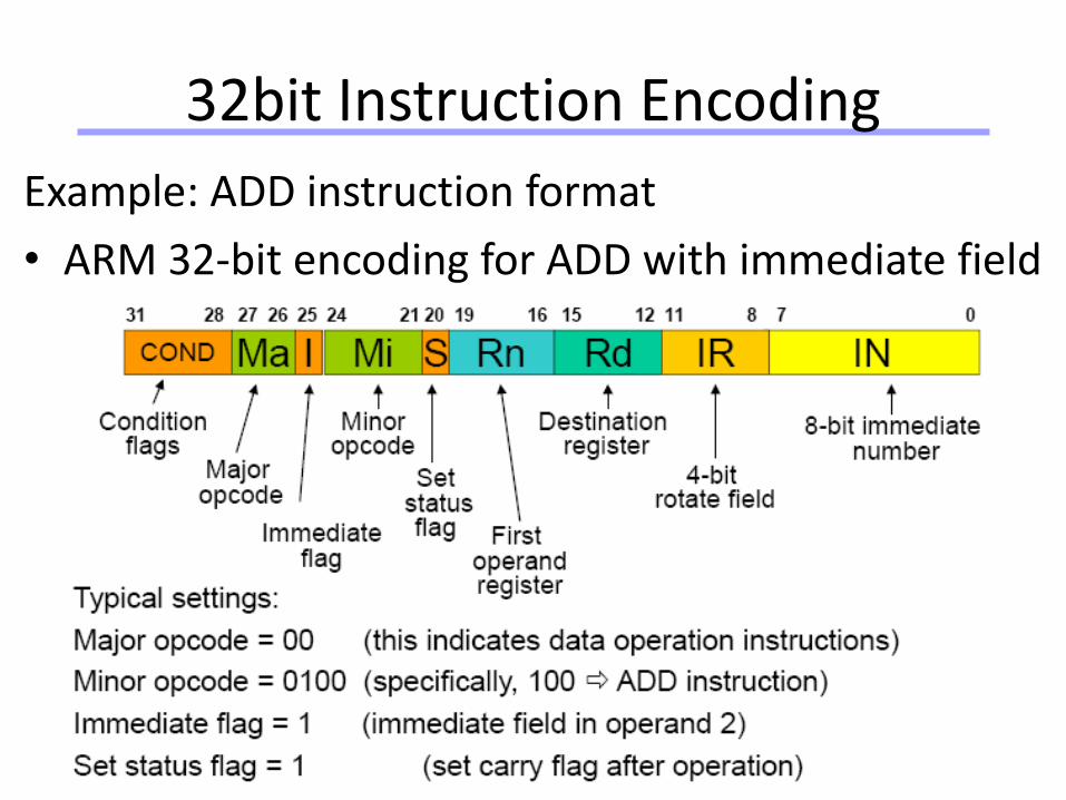
32bit Instruction Encoding
Example: ADD instruction format
• ARM 32-bit encoding for ADD with immediate field
Universität Dortmund
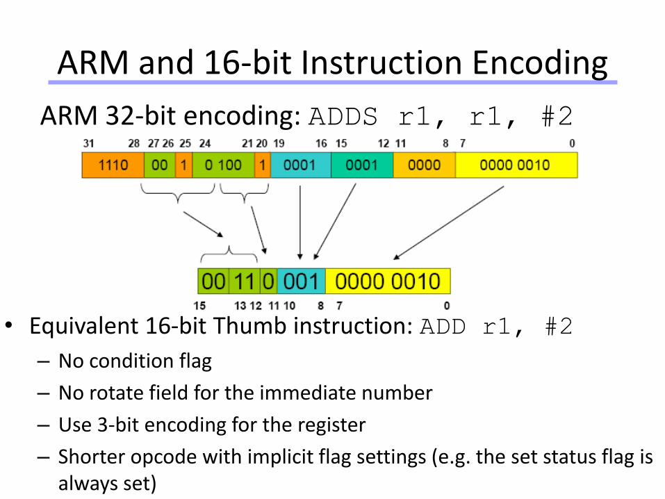
ARM and 16-bit Instruction Encoding
ARM 32-bit encoding: ADDS r1, r1, #2
• Equivalent 16-bit Thumb instruction: ADD r1, #2
– No condition flag
– No rotate field for the immediate number
– Use 3-bit encoding for the register
– Shorter opcode with implicit flag settings (e.g. the set status flag is always set)
Universität Dortmund
Application Program Status Register (APSR)
Universität Dortmund
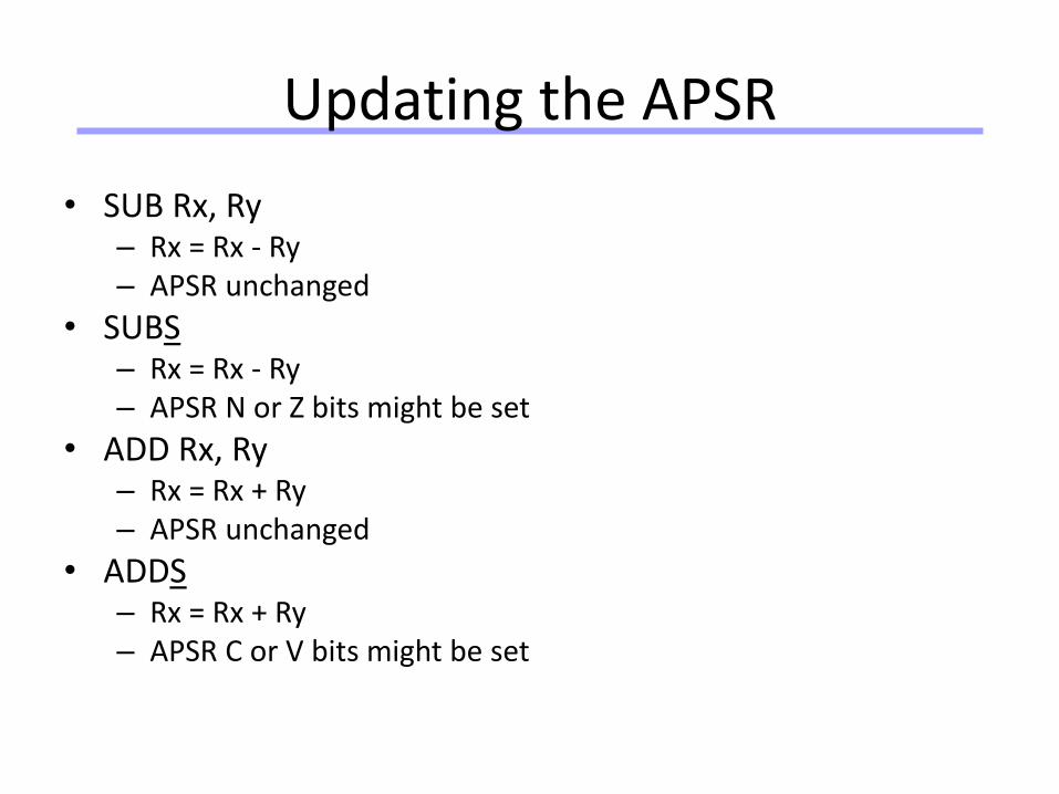
Updating the APSR
• SUB Rx, Ry– Rx = Rx - Ry– APSR unchanged
• SUBS– Rx = Rx - Ry– APSR N or Z bits might be set
• ADD Rx, Ry– Rx = Rx + Ry– APSR unchanged
• ADDS– Rx = Rx + Ry– APSR C or V bits might be set
Universität Dortmund
45
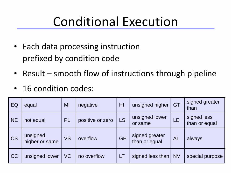
Conditional Execution
• Each data processing instruction
prefixed by condition code
• Result – smooth flow of instructions through pipeline
• 16 condition codes:
EQ equal MI negative HI unsigned higher GTsigned greater
than
NE not equal PL positive or zero LSunsigned lower
or sameLE
signed less
than or equal
CSunsigned
higher or sameVS overflow GE
signed greater
than or equalAL always
CC unsigned lower VC no overflow LT signed less than NV special purpose
Universität Dortmund
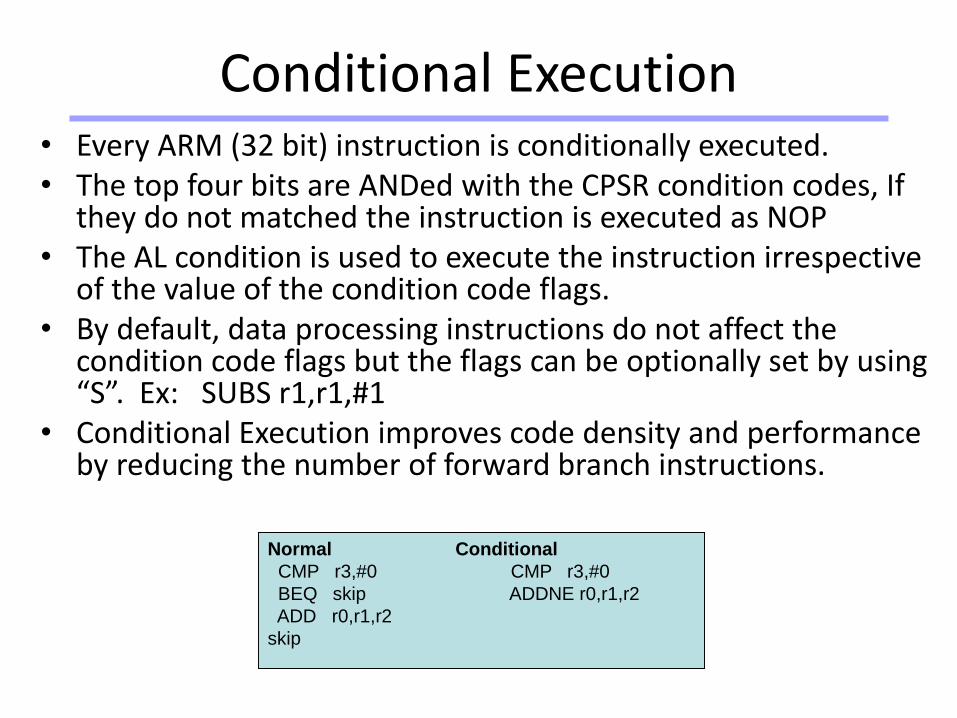
• Every ARM (32 bit) instruction is conditionally executed.• The top four bits are ANDed with the CPSR condition codes, If
they do not matched the instruction is executed as NOP • The AL condition is used to execute the instruction irrespective
of the value of the condition code flags.• By default, data processing instructions do not affect the
condition code flags but the flags can be optionally set by using “S”. Ex: SUBS r1,r1,#1
• Conditional Execution improves code density and performance by reducing the number of forward branch instructions.
Normal Conditional
CMP r3,#0 CMP r3,#0
BEQ skip ADDNE r0,r1,r2
ADD r0,r1,r2
skip
Conditional Execution
Universität Dortmund
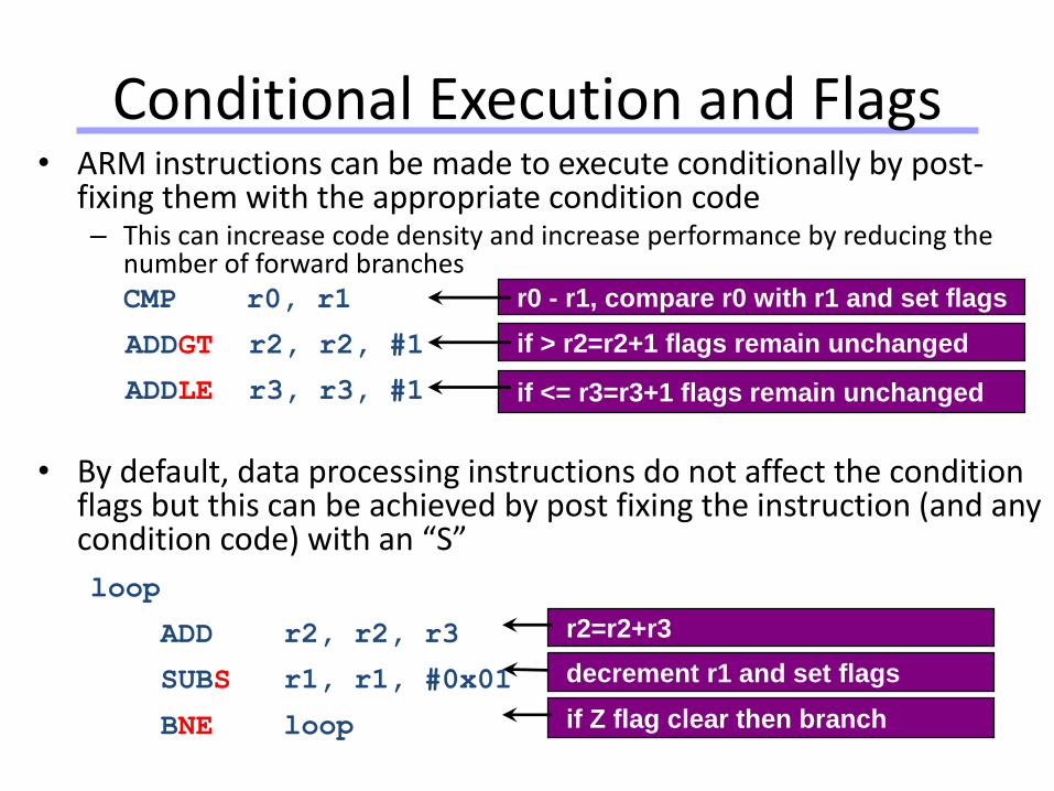
• ARM instructions can be made to execute conditionally by post-fixing them with the appropriate condition code– This can increase code density and increase performance by reducing the
number of forward branchesCMP r0, r1
ADDGT r2, r2, #1
ADDLE r3, r3, #1
• By default, data processing instructions do not affect the condition flags but this can be achieved by post fixing the instruction (and any condition code) with an “S”
loop
ADD r2, r2, r3
SUBS r1, r1, #0x01
BNE loop
r2=r2+r3
if Z flag clear then branch
decrement r1 and set flags
r0 - r1, compare r0 with r1 and set flags
if > r2=r2+1 flags remain unchanged
if <= r3=r3+1 flags remain unchanged
Conditional Execution and Flags
Universität Dortmund
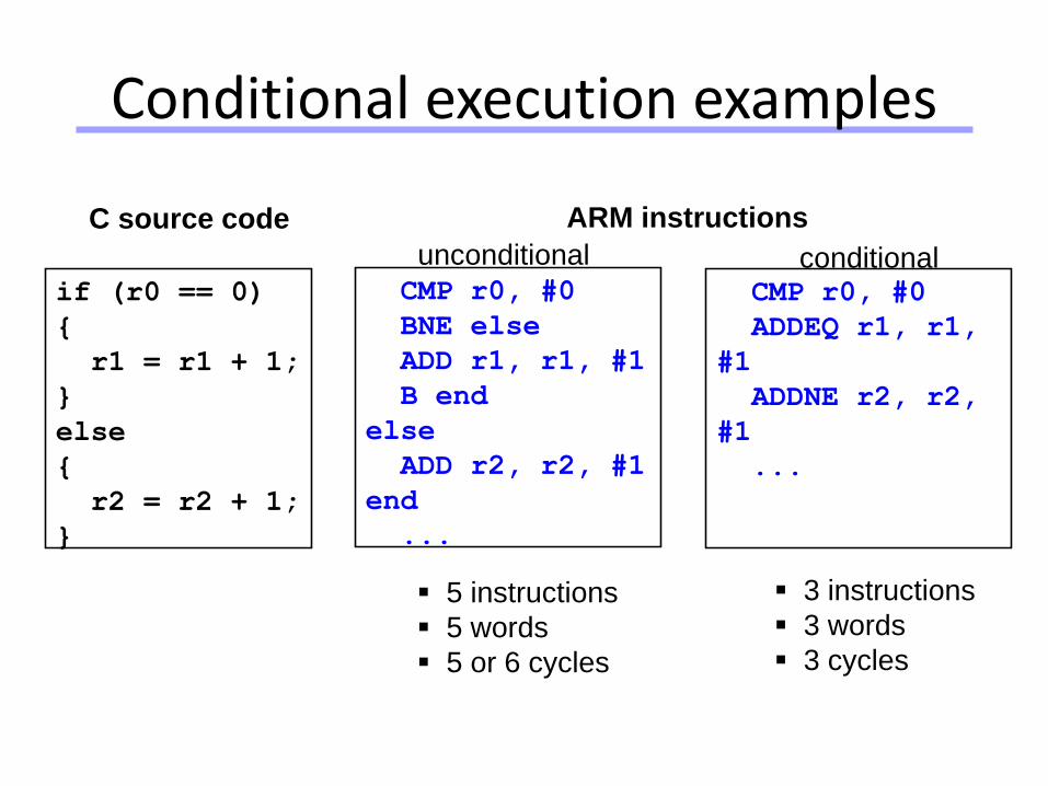
Conditional execution examples
if (r0 == 0)
{
r1 = r1 + 1;
}
else
{
r2 = r2 + 1;
}
C source code
5 instructions
5 words
5 or 6 cycles
3 instructions
3 words
3 cycles
CMP r0, #0
BNE else
ADD r1, r1, #1
B end
else
ADD r2, r2, #1
end
...
ARM instructions
unconditional
CMP r0, #0
ADDEQ r1, r1,
#1
ADDNE r2, r2,
#1
...
conditional
Universität Dortmund
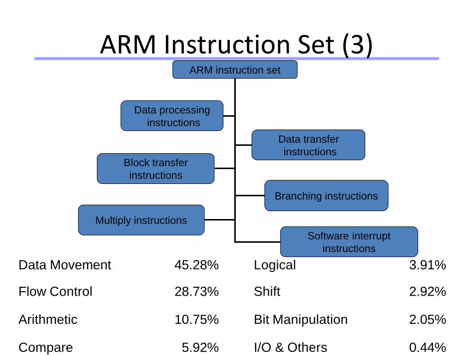
ARM Instruction Set (3)ARM instruction set
Data processing
instructions
Data transfer
instructions
Software interrupt
instructions
Block transfer
instructions
Multiply instructions
Branching instructions
Data Movement 45.28% Logical 3.91%
Flow Control 28.73% Shift 2.92%
Arithmetic 10.75% Bit Manipulation 2.05%
Compare 5.92% I/O & Others 0.44%
Universität Dortmund
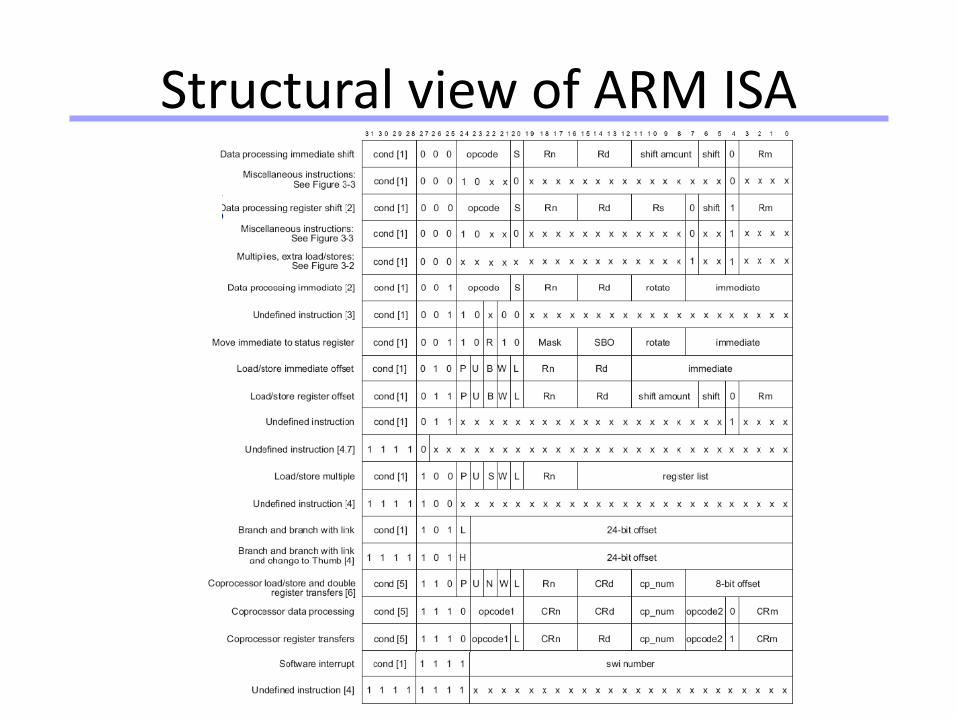
Structural view of ARM ISA
Universität Dortmund
51
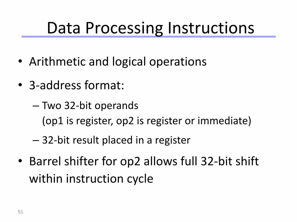
Data Processing Instructions
• Arithmetic and logical operations
• 3-address format:
– Two 32-bit operands
(op1 is register, op2 is register or immediate)
– 32-bit result placed in a register
• Barrel shifter for op2 allows full 32-bit shift
within instruction cycle
Universität Dortmund
52
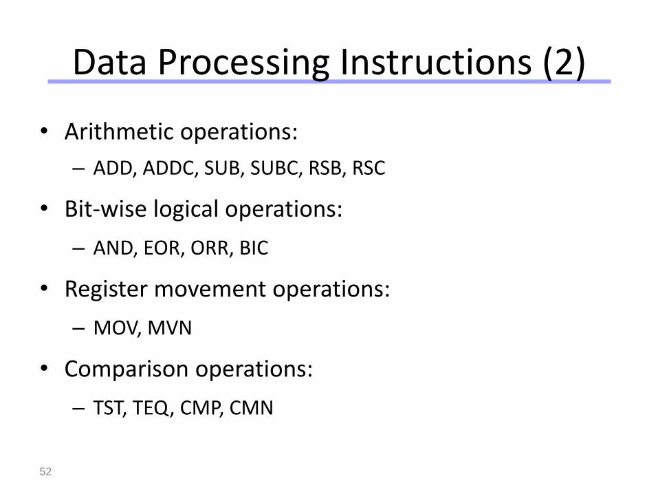
Data Processing Instructions (2)
• Arithmetic operations:
– ADD, ADDC, SUB, SUBC, RSB, RSC
• Bit-wise logical operations:
– AND, EOR, ORR, BIC
• Register movement operations:
– MOV, MVN
• Comparison operations:
– TST, TEQ, CMP, CMN
Universität Dortmund
53
Data Processing Instructions (3)
Conditional codes
+
Data processing instructions
+
Barrel shifter
=
Powerful tools for efficient coded programs
Universität Dortmund
54
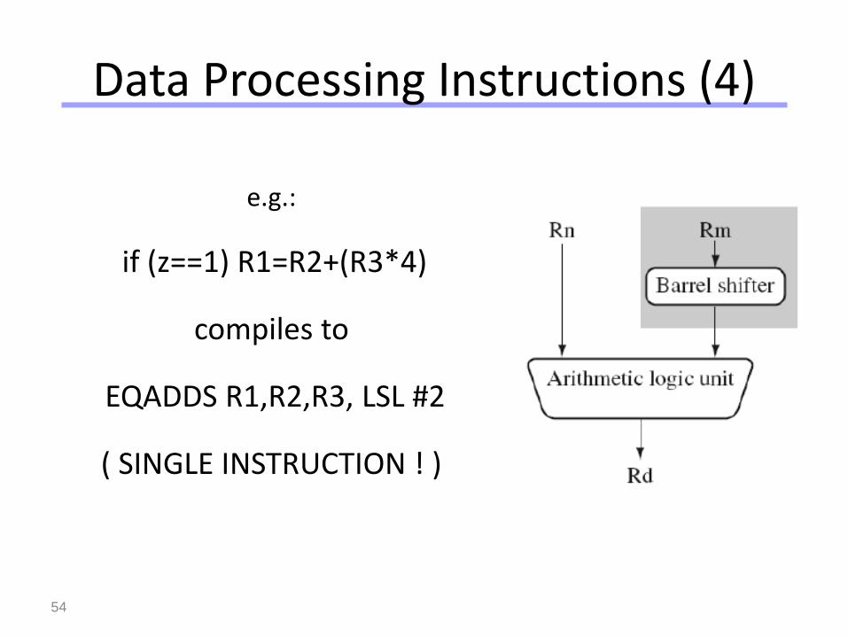
Data Processing Instructions (4)
e.g.:
if (z==1) R1=R2+(R3*4)
compiles to
EQADDS R1,R2,R3, LSL #2
( SINGLE INSTRUCTION ! )
Universität Dortmund
55
Multiply Instructions
• Integer multiplication (32-bit result)
• Long integer multiplication (64-bit result)
• Built in Multiply Accumulate Unit (MAC)
• Multiply and accumulate instructions add product to running total
Universität Dortmund
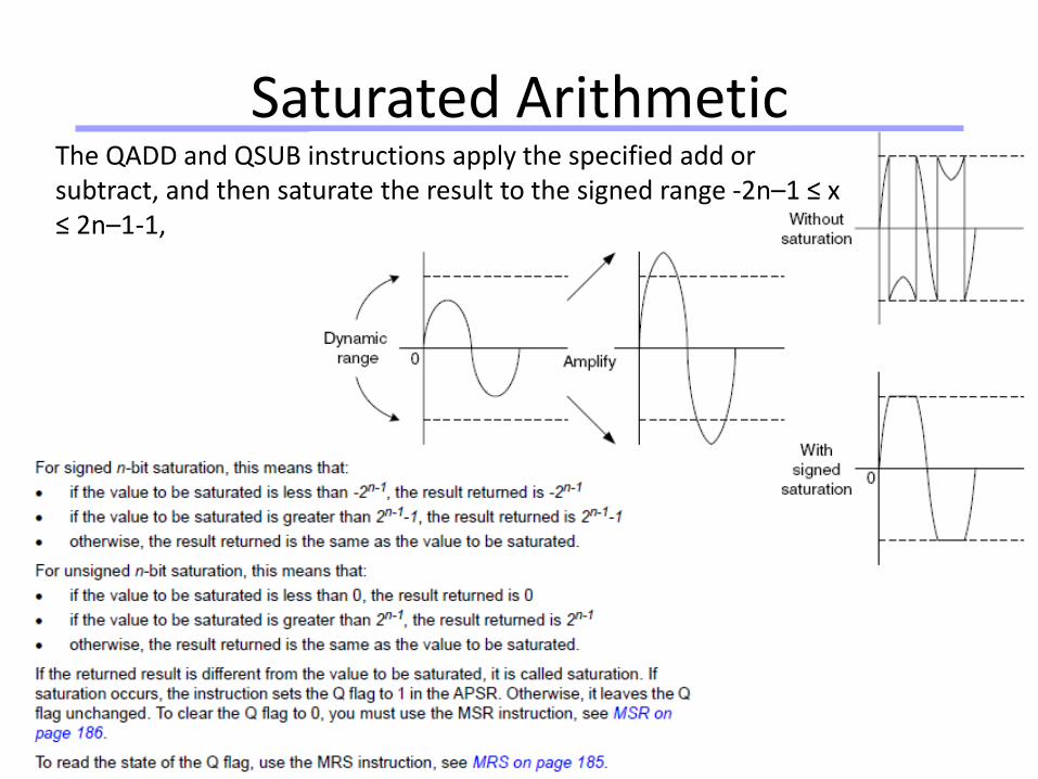
Saturated ArithmeticThe QADD and QSUB instructions apply the specified add or subtract, and then saturate the result to the signed range -2n–1 ≤ x ≤ 2n–1-1,
Universität Dortmund
57
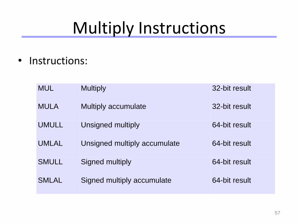
Multiply Instructions
• Instructions:
MUL Multiply 32-bit result
MULA Multiply accumulate 32-bit result
UMULL Unsigned multiply 64-bit result
UMLAL Unsigned multiply accumulate 64-bit result
SMULL Signed multiply 64-bit result
SMLAL Signed multiply accumulate 64-bit result
Universität Dortmund
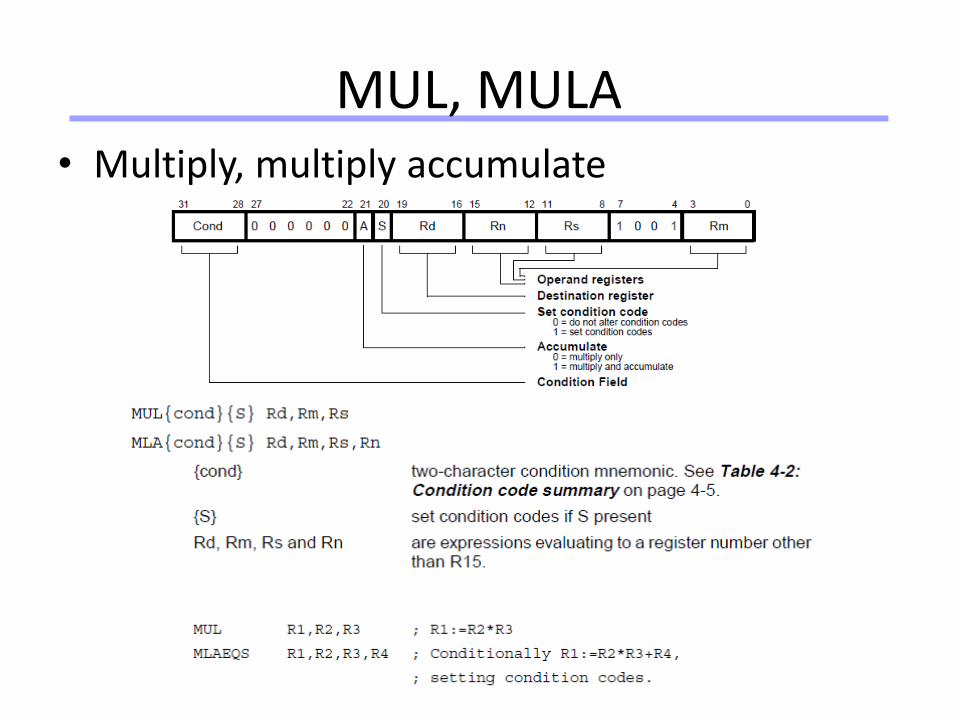
MUL, MULA• Multiply, multiply accumulate
Universität Dortmund
59
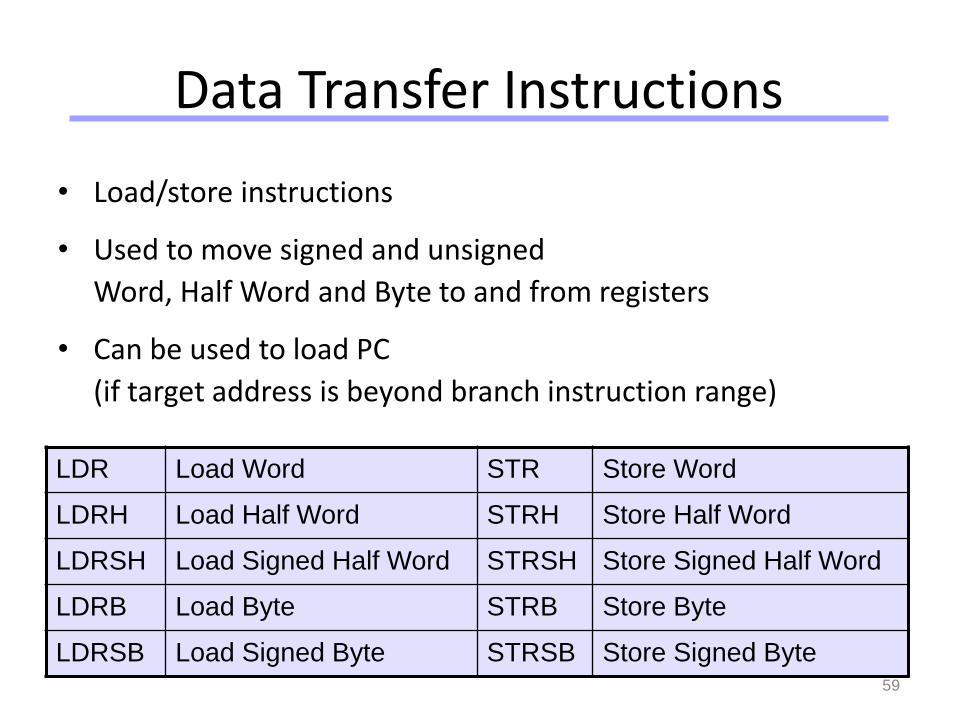
Data Transfer Instructions
• Load/store instructions
• Used to move signed and unsigned
Word, Half Word and Byte to and from registers
• Can be used to load PC
(if target address is beyond branch instruction range)
LDR Load Word STR Store Word
LDRH Load Half Word STRH Store Half Word
LDRSH Load Signed Half Word STRSH Store Signed Half Word
LDRB Load Byte STRB Store Byte
LDRSB Load Signed Byte STRSB Store Signed Byte
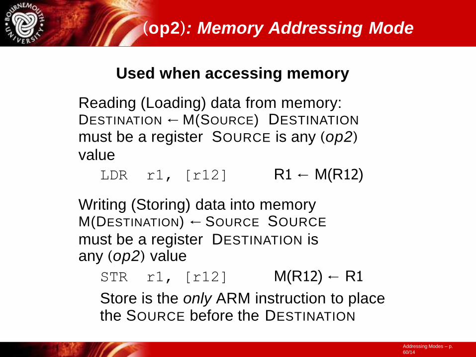
(op2): Memory Addressing Mode
Addressing Modes – p.
60/14
Used when accessing memory
Reading (Loading) data from memory: DESTINATION ← M(SOURCE) DESTINATION
must be a register SOURCE is any (op2)
value
LDR r1, [r12] R1 ← M(R12)
Writing (Storing) data into memory M(DESTINATION) ← SOURCE SOURCE
must be a register DESTINATION is any (op2) value
STR r1, [r12] M(R12) ← R1
Store is the only ARM instruction to place the SOURCE before the DESTINATION
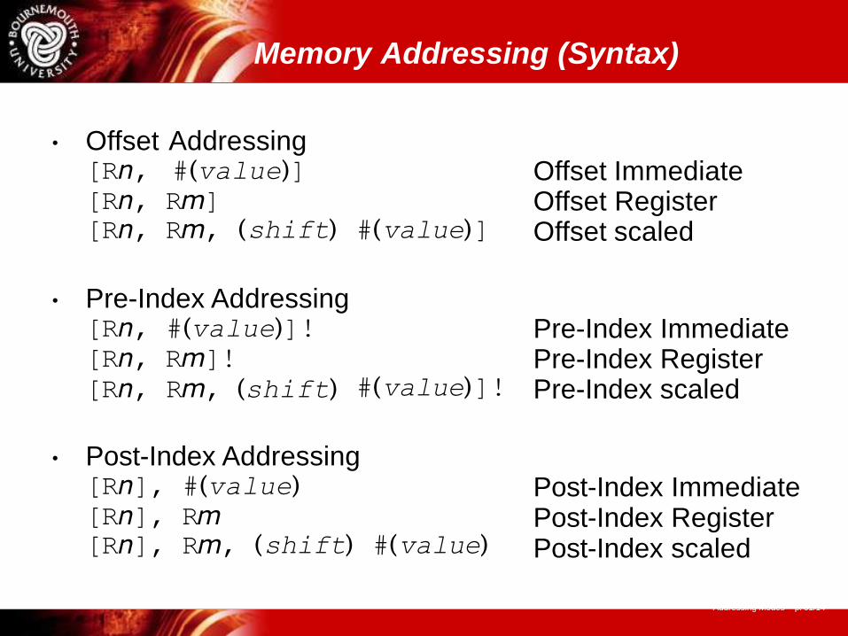
Memory Addressing (Syntax)
Addressing Modes – p. 61/14
• Offset Addressing[Rn, #(value)][Rn, Rm][Rn, Rm, (shift) #(value)]
Offset Immediate Offset Register Offset scaled
• Pre-Index Addressing [Rn, #(value)]! [Rn, Rm]![Rn, Rm, (shift) #(value)]!
Pre-Index Immediate Pre-Index Register Pre-Index scaled
• Post-Index Addressing [Rn], #(value) [Rn], Rm[Rn], Rm, (shift) #(value)
Post-Index Immediate Post-Index Register Post-Index scaled
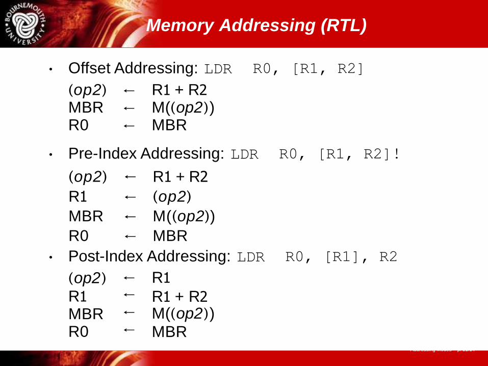
Memory Addressing (RTL)
(op2)
R1 MBR R0
R1
R1 + R2 M((op2)) MBR
←←←←
Addressing Modes – p. 11/14
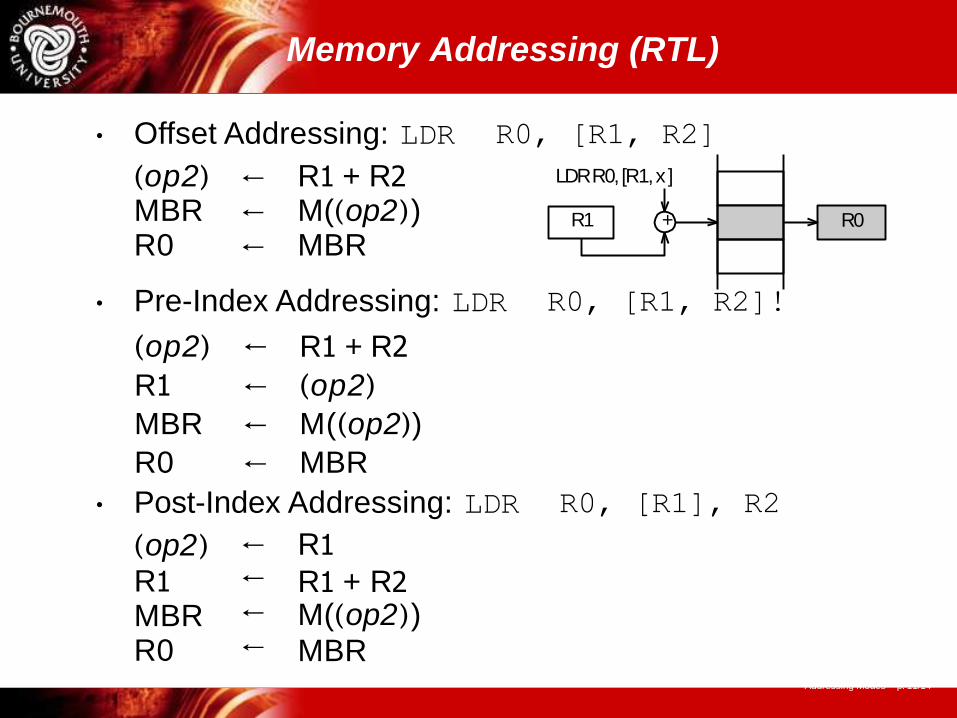
• Offset Addressing: LDR R0, [R1, R2]
(op2) ← R1 + R2 MBR ← M((op2)) R0 ← MBR
• Pre-Index Addressing: LDR R0, [R1, R2]!
(op2) ← R1 + R2
R1 ← (op2)
MBR ← M((op2))
R0 ← MBR
• Post-Index Addressing: LDR R0, [R1], R2
Memory Addressing (RTL)
• Offset Addressing: LDR R0, [R1, R2]
LDR R0, [R1, x ]
R1 + R0
(op2) ← R1 + R2 MBR ← M((op2)) R0 ← MBR
(op2)
R1 MBR R0
R1
R1 + R2 M((op2)) MBR
←←←←
Addressing Modes – p. 11/14
• Pre-Index Addressing: LDR R0, [R1, R2]!
(op2) ← R1 + R2
R1 ← (op2)
MBR ← M((op2))
R0 ← MBR
• Post-Index Addressing: LDR R0, [R1], R2
Memory Addressing (RTL)
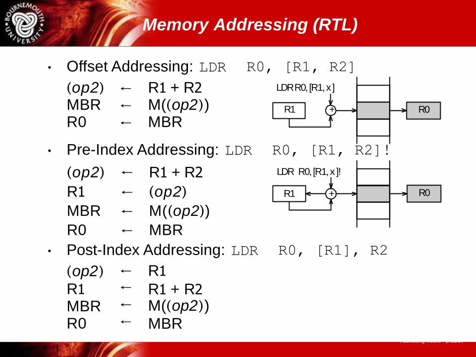
• Offset Addressing: LDR R0, [R1, R2]
LDR R0, [R1, x ]
R1 + R0
(op2) ← R1 + R2 MBR ← M((op2)) R0 ← MBR
• Pre-Index Addressing: LDR R0, [R1, R2]!
LDR R0, [R1, x ]!
R1 + R0
(op2) ← R1 + R2
R1 ← (op2)
MBR ← M((op2))
R0 ← MBR
(op2)
R1 MBR R0
R1
R1 + R2 M((op2)) MBR
←←←←
Addressing Modes – p. 11/14
• Post-Index Addressing: LDR R0, [R1], R2
Memory Addressing (RTL)
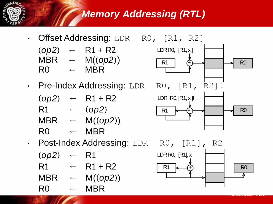
• Offset Addressing: LDR R0, [R1, R2]
LDR R0, [R1, x ]
R1 + R0
(op2) ← R1 + R2 MBR ← M((op2)) R0 ← MBR
• Pre-Index Addressing: LDR R0, [R1, R2]!
LDR R0, [R1, x ]!
R1 + R0
(op2) ← R1 + R2
R1 ← (op2)
MBR ← M((op2))
R0 ← MBR
• Post-Index Addressing: LDR R0, [R1], R2
LDR R0, [R1], x
R1 + R0
(op2)
R1
←
←
R1
R1 + R2
MBR ← M((op2))
R0 ← MBRAddressing Modes – p. 11/14
Universität Dortmund
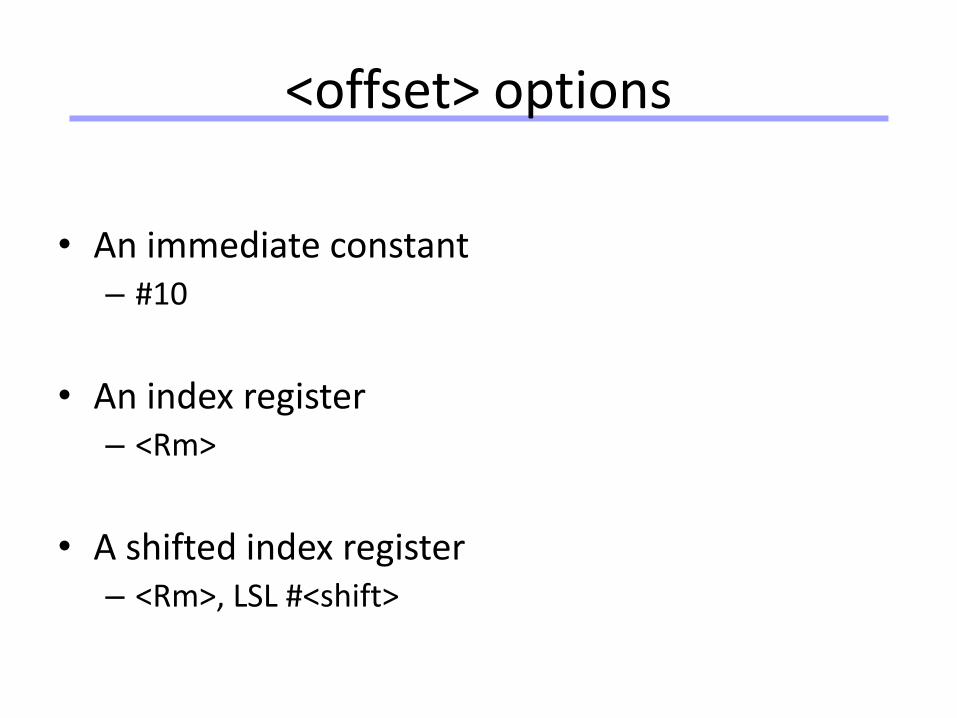
<offset> options
• An immediate constant– #10
• An index register– <Rm>
• A shifted index register– <Rm>, LSL #<shift>
Universität Dortmund
67
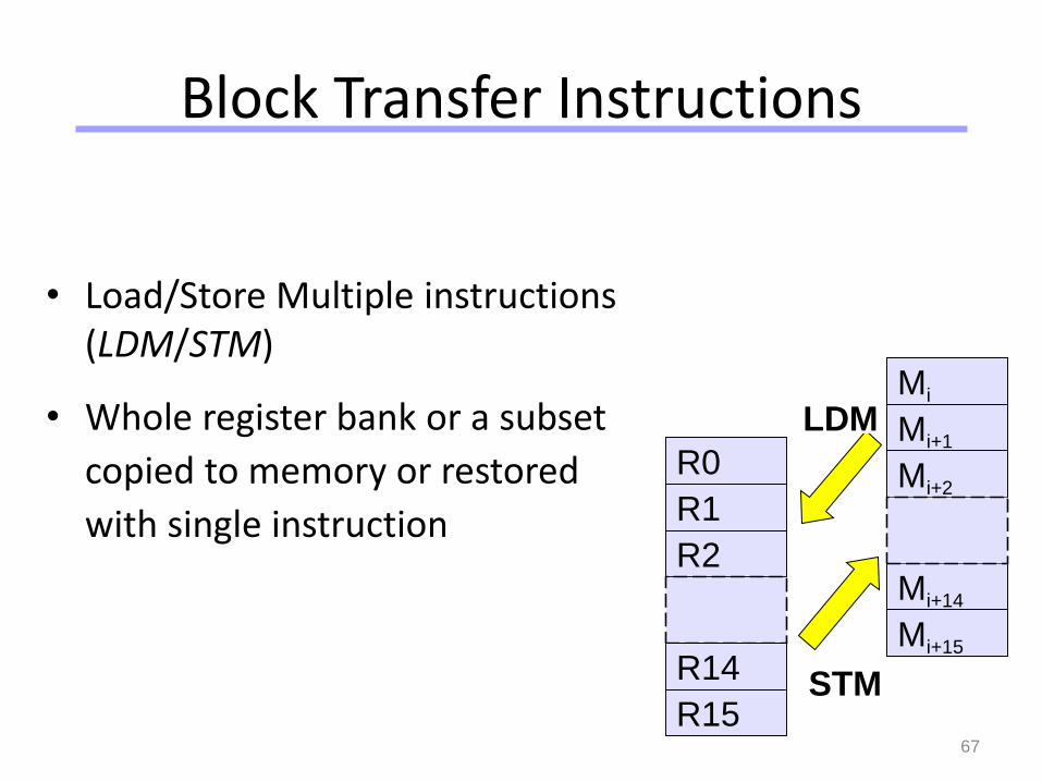
Block Transfer Instructions
• Load/Store Multiple instructions (LDM/STM)
• Whole register bank or a subset
copied to memory or restored
with single instruction
R0
R1
R2
R14
R15
Mi
Mi+1
Mi+2
Mi+14
Mi+15
LDM
STM
Universität Dortmund
68
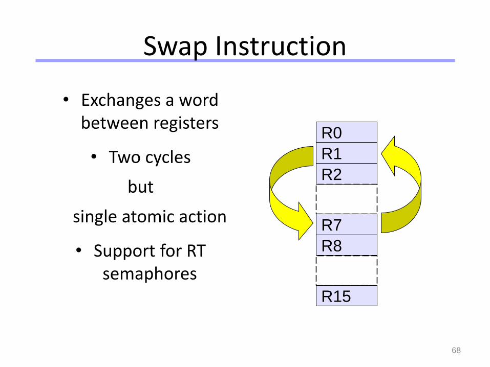
Swap Instruction
• Exchanges a word between registers
• Two cycles
but
single atomic action
• Support for RT semaphores
R0
R1
R2
R7
R8
R15
Universität Dortmund
69
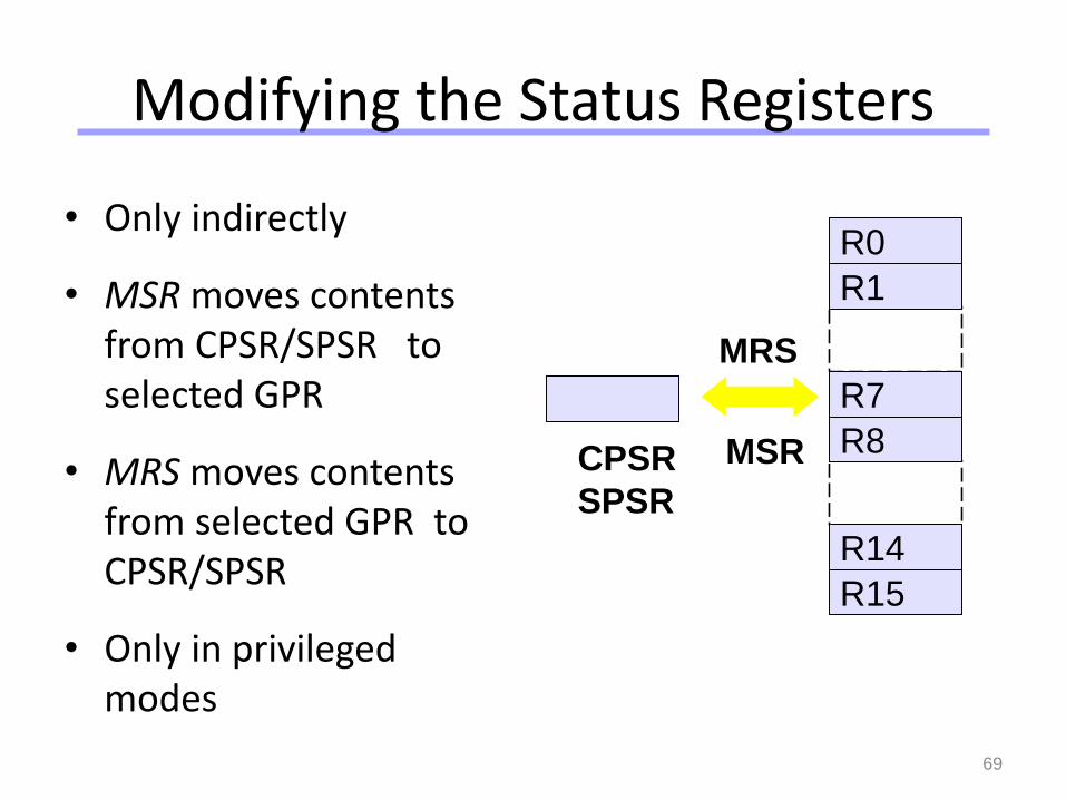
Modifying the Status Registers
• Only indirectly
• MSR moves contents from CPSR/SPSR to selected GPR
• MRS moves contents from selected GPR to CPSR/SPSR
• Only in privileged modes
R0
R1
R7
R8
R14
R15
CPSR
SPSR
MSR
MRS
Universität Dortmund
70
Branching Instructions
• Branch (B):jumps forwards/backwards up to 32 MB
• Branch link (BL):
same + saves (PC+4) in LR
• Suitable for function call/return
• Condition codes for conditional branches
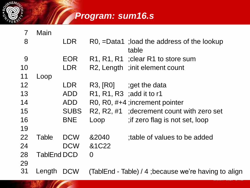
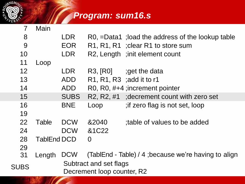
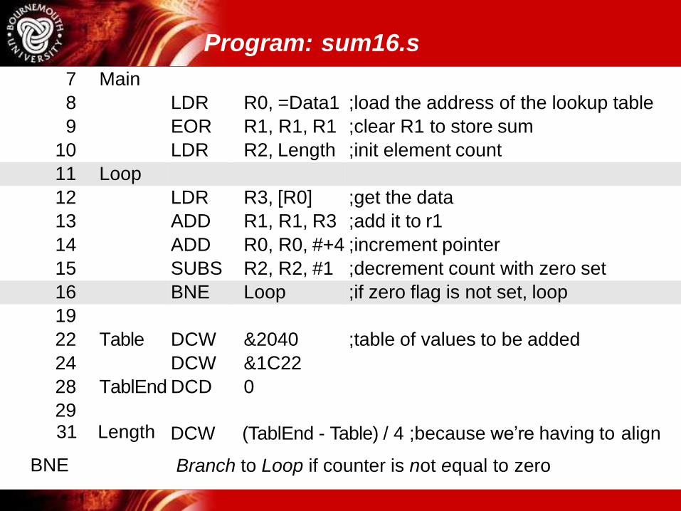
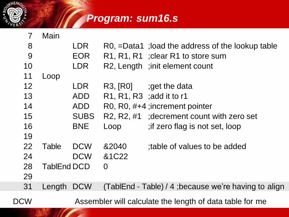
Program: sum16.s
Structure / Loops – p. 7/12
7 Main
8 LDR R0, =Data1 ;load the address of the lookup
table
9 EOR R1, R1, R1 ;clear R1 to store sum
10 LDR R2, Length ;init element count
11 Loop
12 LDR R3, [R0] ;get the data
13 ADD R1, R1, R3 ;add it to r1
14 ADD R0, R0, #+4 ;increment pointer
15 SUBS R2, R2, #1 ;decrement count with zero set
16 BNE Loop ;if zero flag is not set, loop
19
22 Table DCW &2040 ;table of values to be added
24 DCW &1C22
28 TablEnd DCD 0
2931 Length DCW (TablEnd - Table) / 4 ;because we’re having to align
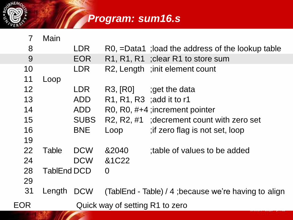
Program: sum16.s
Structure / Loops – p. 7/12
7 Main
8 LDR R0, =Data1 ;load the address of the lookup table
9 EOR R1, R1, R1 ;clear R1 to store sum
10 LDR R2, Length ;init element count
11 Loop
12 LDR R3, [R0] ;get the data
13 ADD R1, R1, R3 ;add it to r1
14 ADD R0, R0, #+4 ;increment pointer
15 SUBS R2, R2, #1 ;decrement count with zero set
16 BNE Loop ;if zero flag is not set, loop
19
22 Table DCW &2040 ;table of values to be added
24 DCW &1C22
28 TablEnd DCD 0
29
DCW (TablEnd - Table) / 4 ;because we’re having to align31 Length
EOR Quick way of setting R1 to zero
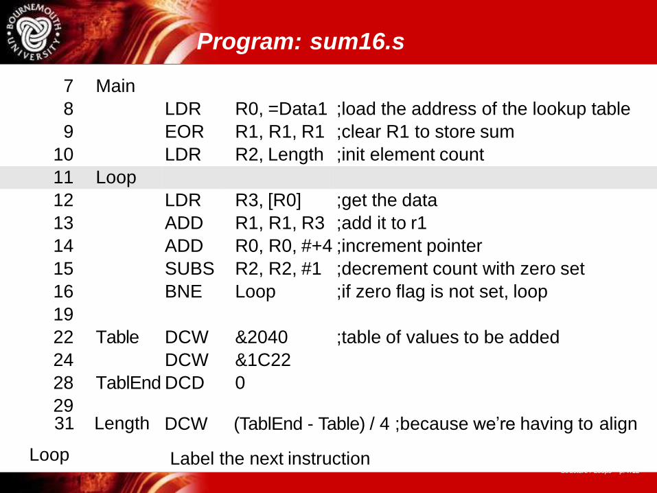
Program: sum16.s
Structure / Loops – p. 7/12
7 Main
8 LDR R0, =Data1 ;load the address of the lookup table
9 EOR R1, R1, R1 ;clear R1 to store sum
10 LDR R2, Length ;init element count
11 Loop
12 LDR R3, [R0] ;get the data
13 ADD R1, R1, R3 ;add it to r1
14 ADD R0, R0, #+4 ;increment pointer
15 SUBS R2, R2, #1 ;decrement count with zero set
16 BNE Loop ;if zero flag is not set, loop
19
22 Table DCW &2040 ;table of values to be added
24 DCW &1C22
28 TablEnd DCD 0
29DCW (TablEnd - Table) / 4 ;because we’re having to align31 Length
Loop Label the next instruction
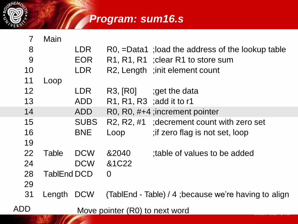
Program: sum16.s
Structure / Loops – p. 7/12
7 Main
8 LDR R0, =Data1 ;load the address of the lookup table
9 EOR R1, R1, R1 ;clear R1 to store sum
10 LDR R2, Length ;init element count
11 Loop
12 LDR R3, [R0] ;get the data
13 ADD R1, R1, R3 ;add it to r1
14 ADD R0, R0, #+4 ;increment pointer
15 SUBS R2, R2, #1 ;decrement count with zero set
16 BNE Loop ;if zero flag is not set, loop
19
22 Table DCW &2040 ;table of values to be added
24 DCW &1C22
28 TablEnd DCD 0
29
DCW (TablEnd - Table) / 4 ;because we’re having to align31 Length
ADD Move pointer (R0) to next word

Program: sum16.s
7 Main
8 LDR R0, =Data1 ;load the address of the lookup table
9 EOR R1, R1, R1 ;clear R1 to store sum
10 LDR R2, Length ;init element count
11 Loop
12 LDR R3, [R0] ;get the data
13 ADD R1, R1, R3 ;add it to r1
14 ADD R0, R0, #+4 ;increment pointer
15 SUBS R2, R2, #1 ;decrement count with zero set
16 BNE Loop ;if zero flag is not set, loop
19
22 Table DCW &2040 ;table of values to be added
24 DCW &1C22
28 TablEnd DCD 0
2931 Length
LDR/ADD
DCW (TablEnd - Table) / 4 ;because we’re having to align
Using Post-index addressing we can remove the ADD:
LDR R3, [R0], #4
Program: sum16.s
7 Main
8 LDR R0, =Data1 ;load the address of the lookup table
9 EOR R1, R1, R1 ;clear R1 to store sum
10 LDR R2, Length ;init element count
11 Loop
12 LDR R3, [R0] ;get the data
13 ADD R1, R1, R3 ;add it to r1
14 ADD R0, R0, #+4 ;increment pointer
15 SUBS R2, R2, #1 ;decrement count with zero set
16 BNE Loop ;if zero flag is not set, loop
19
22 Table DCW &2040 ;table of values to be added
24 DCW &1C22
28 TablEnd DCD 0
29DCW (TablEnd - Table) / 4 ;because we’re having to align31 Length
SUBSSubtract and set flags Decrement loop counter, R2
Program: sum16.s
7 Main
8 LDR R0, =Data1 ;load the address of the lookup table
9 EOR R1, R1, R1 ;clear R1 to store sum
10 LDR R2, Length ;init element count
11 Loop
12 LDR R3, [R0] ;get the data
13 ADD R1, R1, R3 ;add it to r1
14 ADD R0, R0, #+4 ;increment pointer
15 SUBS R2, R2, #1 ;decrement count with zero set
16 BNE Loop ;if zero flag is not set, loop
19
22 Table DCW &2040 ;table of values to be added
24 DCW &1C22
28 TablEnd DCD 0
29
DCW (TablEnd - Table) / 4 ;because we’re having to align31 Length
BNE Branch to Loop if counter is not equal to zero
Program: sum16.s
7 Main
8 LDR R0, =Data1 ;load the address of the lookup table
9 EOR R1, R1, R1 ;clear R1 to store sum
10 LDR R2, Length ;init element count
11 Loop
12 LDR R3, [R0] ;get the data
13 ADD R1, R1, R3 ;add it to r1
14 ADD R0, R0, #+4 ;increment pointer
15 SUBS R2, R2, #1 ;decrement count with zero set
16 BNE Loop ;if zero flag is not set, loop
19
22 Table DCW &2040 ;table of values to be added
24 DCW &1C22
28 TablEnd DCD 0
29
31 Length DCW (TablEnd - Table) / 4 ;because we’re having to align
DCW Assembler will calculate the length of data table for me
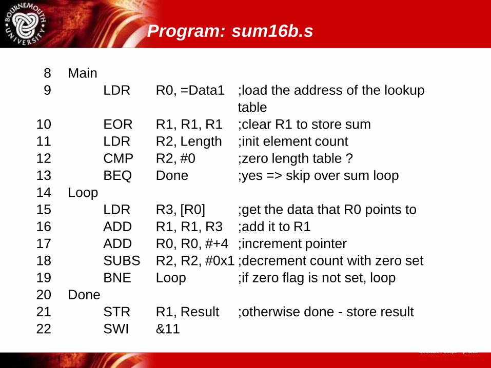
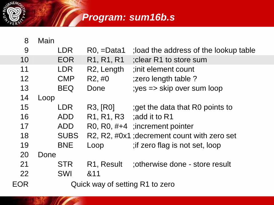
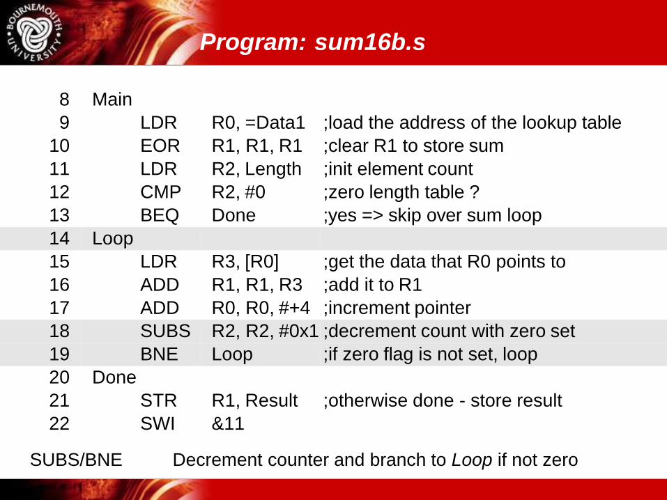
Program: sum16b.s
Structure / Loops – p. 8/12
8 Main
9 LDR R0, =Data1 ;load the address of the lookup
table
10 EOR R1, R1, R1 ;clear R1 to store sum
11 LDR R2, Length ;init element count
12 CMP R2, #0 ;zero length table ?
13 BEQ Done ;yes => skip over sum loop
14 Loop
15 LDR R3, [R0] ;get the data that R0 points to
16 ADD R1, R1, R3 ;add it to R1
17 ADD R0, R0, #+4 ;increment pointer
18 SUBS R2, R2, #0x1 ;decrement count with zero set
19 BNE Loop ;if zero flag is not set, loop
20 Done
21 STR R1, Result ;otherwise done - store result
22 SWI &11
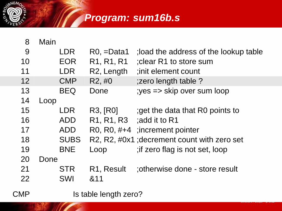
Program: sum16b.s
8 Main
9 LDR R0, =Data1 ;load the address of the lookup table
10 EOR R1, R1, R1 ;clear R1 to store sum
11 LDR R2, Length ;init element count
12 CMP R2, #0 ;zero length table ?
13 BEQ Done ;yes => skip over sum loop
14 Loop
15 LDR R3, [R0] ;get the data that R0 points to
16 ADD R1, R1, R3 ;add it to R1
17 ADD R0, R0, #+4 ;increment pointer
18 SUBS R2, R2, #0x1 ;decrement count with zero set
19 BNE Loop ;if zero flag is not set, loop
20 Done
21 STR R1, Result ;otherwise done - store result
22 SWI &11
EOR Quick way of setting R1 to zero
Program: sum16b.s
Structure / Loops – p. 8/12
8 Main
9 LDR R0, =Data1 ;load the address of the lookup table
10 EOR R1, R1, R1 ;clear R1 to store sum
11 LDR R2, Length ;init element count
12 CMP R2, #0 ;zero length table ?
13 BEQ Done ;yes => skip over sum loop
14 Loop
15 LDR R3, [R0] ;get the data that R0 points to
16 ADD R1, R1, R3 ;add it to R1
17 ADD R0, R0, #+4 ;increment pointer
18 SUBS R2, R2, #0x1 ;decrement count with zero set
19 BNE Loop ;if zero flag is not set, loop
20 Done
21 STR R1, Result ;otherwise done - store result
22 SWI &11
CMP Is table length zero?
Program: sum16b.s
Structure / Loops – p. 8/12
8 Main
9 LDR R0, =Data1 ;load the address of the lookup table
10 EOR R1, R1, R1 ;clear R1 to store sum
11 LDR R2, Length ;init element count
12 CMP R2, #0 ;zero length table ?
13 BEQ Done ;yes => skip over sum loop
14 Loop
15 LDR R3, [R0] ;get the data that R0 points to
16 ADD R1, R1, R3 ;add it to R1
17 ADD R0, R0, #+4 ;increment pointer
18 SUBS R2, R2, #0x1 ;decrement count with zero set
19 BNE Loop ;if zero flag is not set, loop
20 Done
21 STR R1, Result ;otherwise done - store result
22 SWI &11
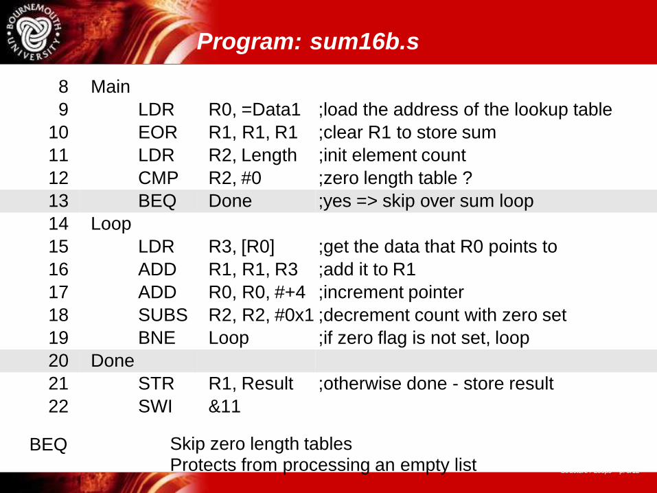
BEQ Skip zero length tablesProtects from processing an empty list
Program: sum16b.s
8 Main
9 LDR R0, =Data1 ;load the address of the lookup table
10 EOR R1, R1, R1 ;clear R1 to store sum
11 LDR R2, Length ;init element count
12 CMP R2, #0 ;zero length table ?
13 BEQ Done ;yes => skip over sum loop
14 Loop
15 LDR R3, [R0] ;get the data that R0 points to
16 ADD R1, R1, R3 ;add it to R1
17 ADD R0, R0, #+4 ;increment pointer
18 SUBS R2, R2, #0x1 ;decrement count with zero set
19 BNE Loop ;if zero flag is not set, loop
20 Done
21 STR R1, Result ;otherwise done - store result
22 SWI &11
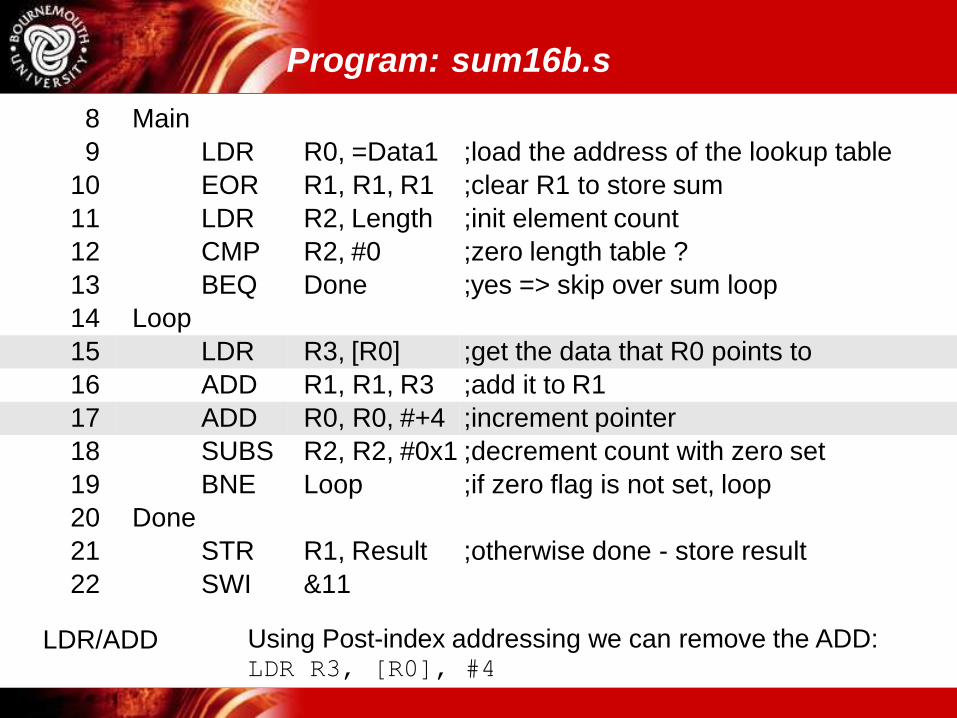
LDR/ADD Using Post-index addressing we can remove the ADD:LDR R3, [R0], #4
Program: sum16b.s
8 Main
9 LDR R0, =Data1 ;load the address of the lookup table
10 EOR R1, R1, R1 ;clear R1 to store sum
11 LDR R2, Length ;init element count
12 CMP R2, #0 ;zero length table ?
13 BEQ Done ;yes => skip over sum loop
14 Loop
15 LDR R3, [R0] ;get the data that R0 points to
16 ADD R1, R1, R3 ;add it to R1
17 ADD R0, R0, #+4 ;increment pointer
18 SUBS R2, R2, #0x1 ;decrement count with zero set
19 BNE Loop ;if zero flag is not set, loop
20 Done
21 STR R1, Result ;otherwise done - store result
22 SWI &11
SUBS/BNE Decrement counter and branch to Loop if not zero
Universität Dortmund
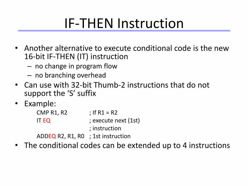
IF-THEN Instruction
• Another alternative to execute conditional code is the new 16-bit IF-THEN (IT) instruction– no change in program flow– no branching overhead
• Can use with 32-bit Thumb-2 instructions that do not support the ‘S’ suffix
• Example:CMP R1, R2 ; If R1 = R2IT EQ ; execute next (1st)
; instructionADDEQ R2, R1, R0 ; 1st instruction
• The conditional codes can be extended up to 4 instructions
Universität Dortmund
86
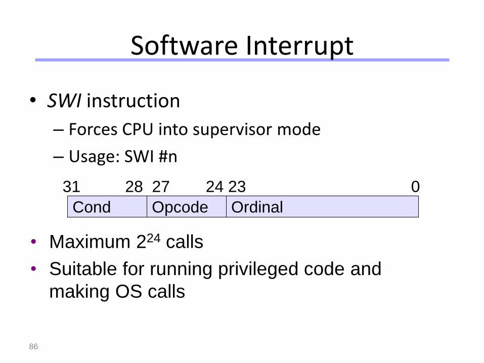
Software Interrupt
• SWI instruction
– Forces CPU into supervisor mode
– Usage: SWI #n
• Maximum 224 calls
• Suitable for running privileged code and
making OS calls
Cond Opcode Ordinal
31 28 27 24 23 0
Universität Dortmund
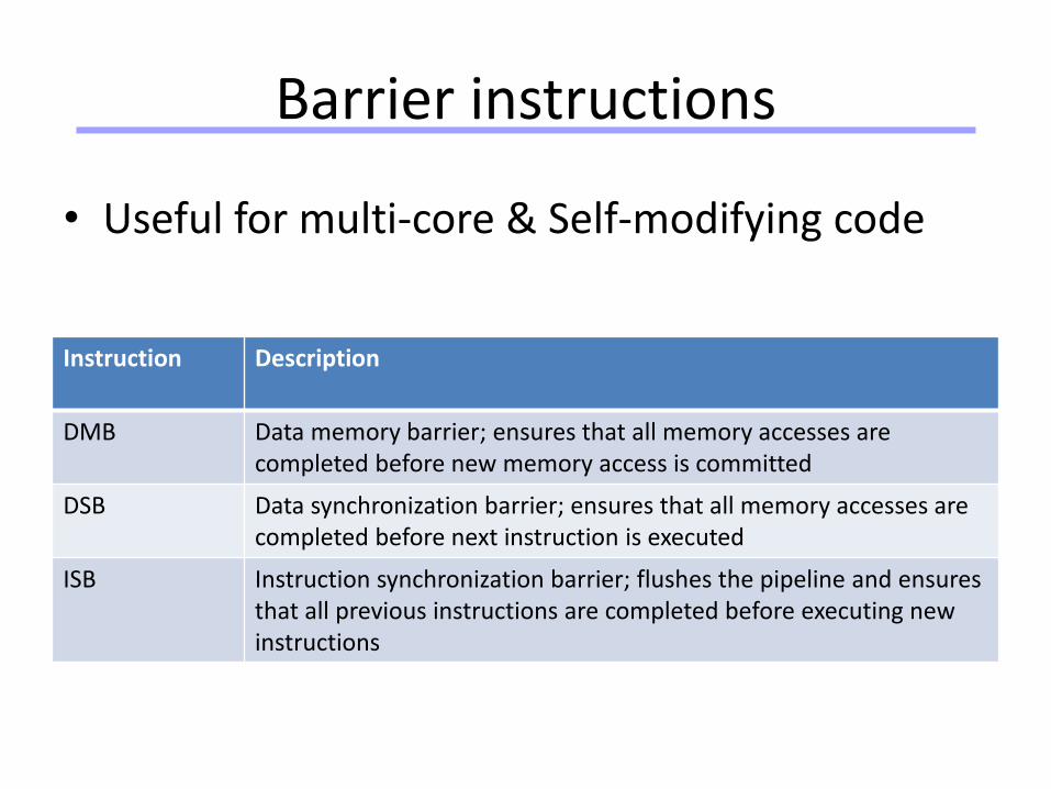
Barrier instructions
Instruction Description
DMB Data memory barrier; ensures that all memory accesses are completed before new memory access is committed
DSB Data synchronization barrier; ensures that all memory accesses are completed before next instruction is executed
ISB Instruction synchronization barrier; flushes the pipeline and ensures that all previous instructions are completed before executing new instructions
• Useful for multi-core & Self-modifying code