Embed Size (px)
Citation preview
ARMYSBIR 08.3 PROPOSAL SUBMISSION INSTRUCTIONS
The US Army Research, Development, and Engineering Command (RDECOM) is responsible for execution of the Army SBIR Program. Information on the Army SBIR Program can be found at the following Web site: https://www.armysbir.com/.
Solicitation, topic, and general questions regarding the SBIR Program should be addressed according to the DoD portion of this solicitation. For technical questions about the topic during the pre-Solicitation period, contact the Topic Authors listed for each topic in the Solicitation. To obtain answers to technical questions during the formal Solicitation period, visit http://www.dodsbir.net/sitis. For general inquiries or problems with the electronic submission, contact the DoD Help Desk at 1-866-724-7457 (8:00 am to 5:00 pm EST). Specific questions pertaining to the Army SBIR Program should be submitted to:
John PucciProgram Manager, Army [email protected]
US Army Research, Development, and Engineering Command (RDECOM)ATTN: AMSRD-SS-SBIR6000 - 6th Street, Suite 100Fort Belvoir, VA 22060-5608(703) 806-2085FAX: (703) 806-2044
The Army participates in three DoD SBIR Solicitations each year. Proposals not conforming to the terms of this Solicitation will not be considered. The Army reserves the right to limit awards under any topic, and only those proposals of superior scientific and technical quality will be funded. Only Government personnel will evaluate proposals. SUBMISSION OF ARMY SBIR PROPOSALS
The entire proposal (which includes Cover Sheets, Technical Proposal, Cost Proposal, and Company Commercialization Report) must be submitted electronically via the DoD SBIR/STTR Proposal Submission Site (http://www.dodsbir.net/submission). The Army prefers that small businesses complete the Cost Proposal form on the DoD Submission site, versus submitting within the body of the uploaded proposal. The Army WILL NOT accept any proposals which are not submitted via this site. Do not send a hardcopy of the proposal. Hand or electronic signature on the proposal is also NOT required. If the proposal is selected for award, the DoD Component program will contact you for signatures. If you experience problems uploading a proposal, call the DoD Help Desk 1-866-724-7457 (8:00 am to 5:00 pm EST). Selection and non-selection letters will be sent electronically via e-mail.
Army Phase I proposals have a 20-page limit (excluding the Cost Proposal and the Company Commercialization Report). Pages in excess of the 20-page limitation will not be considered in the evaluation of the proposal (including attachments, appendices, or references, but excluding the Cost Proposal and Company Commercialization Report).
ARMY-1

Any proposal involving the use of Bio Hazard Materials must identify in the Technical Proposal whether the contractor has been certified by the Government to perform Bio Level - I, II or III work.
Companies should plan carefully for research involving animal or human subjects, or requiring access to government resources of any kind. Animal or human research must be based on formal protocols that are reviewed and approved both locally and through the Army's committee process. Resources such as equipment, reagents, samples, data, facilities, troops or recruits, and so forth, must all be arranged carefully. The few months available for a Phase I effort may preclude plans including these elements, unless coordinated before a contract is awarded.
If the offeror proposes to use a foreign national(s) [any person who is NOT a citizen or national of the United States, a lawful permanent resident, or a protected individual as defined by 8 U.S.C. 1324b(a)(3) – refer to Section 2.15 at the front of this solicitation for definitions of “lawful permanent resident” and “protected individual”] as key personnel, they must be clearly identified. For foreign nationals, you must provide resumes, country of origin and an explanation of the individual’s involvement.
No Class 1 Ozone Depleting Chemicals/Ozone Depleting Substances will be allowed for use in this procurement without prior Government approval.
Phase I Proposals must describe the "vision" or "end-state" of the research and the most likely strategy or path for transition of the SBIR project from research to an operational capability that satisfies one or more Army operational or technical requirements in a new or existing system, larger research program, or as a stand-alone product or service.
PHASE I OPTION MUST BE INCLUDED AS PART OF PHASE I PROPOSAL
The Army implemented the use of a Phase I Option that may be exercised to fund interim Phase I activities while a Phase II contract is being negotiated. Only Phase I efforts selected for Phase II awards through the Army’s competitive process will be eligible to exercise the Phase I Option. The Phase I Option, which must be included as part of the Phase I proposal, covers activities over a period of up to four months and should describe appropriate initial Phase II activities that may lead to the successful demonstration of a product or technology. The Phase I Option must be included within the 20-page limit for the Phase I proposal.
A firm-fixed-price or cost-plus-fixed-fee Phase I Cost Proposal ($120,000 maximum) must be submitted in detail online. Proposers that participate in this Solicitation must complete the Phase I Cost Proposal not to exceed the maximum dollar amount of $70,000 and a Phase I Option Cost Proposal (if applicable) not to exceed the maximum dollar amount of $50,000. Phase I and Phase I Option costs must be shown separately but may be presented side-by-side on a single Cost Proposal. The Cost Proposal DOES NOT count toward the 20-page Phase I proposal limitation.
Phase I Key Dates08.3 Solicitation Pre-release July 28 – August 24, 200808.3 Solicitation Opens August 25 – September 24, 2008Phase I Evaluations September – November 2008Phase I Selections November 2008Phase I Awards January 2009*
*Subject to the Congressional Budget process
ARMY-2

PHASE II PROPOSAL SUBMISSION
Note! Phase II Proposal Submission is by Army Invitation only.
For Phase II, no separate solicitation will be issued and no unsolicited proposals will be accepted. Only those firms that were awarded Phase I contracts, and have successfully completed their Phase Iefforts, will be invited to submit a Phase II proposal. Invitations to submit Phase II proposals will be released at or before the end of the Phase I period of performance. The decision to invite a Phase IIproposal will be made based upon the success of the Phase I contract to meet the technical goals of the topic, as well as the overall merit based upon the criteria in section 4.3. DoD is not obligated to makeany awards under Phase I, II, or III. DoD is not responsible for any money expended by the proposer before award of any contract. For specifics regarding the evaluation and award of Phase I or II contracts,please read the front section of this solicitation very carefully. Every Phase II proposal will be reviewed for overall merit based upon the criteria in section 4.3 of this solicitation, repeated below:
a. The soundness, technical merit, and innovation of the proposed approach and its incremental progress toward topic or subtopic solution.b. The qualifications of the proposed principal/key investigators, supporting staff, and consultants. Qualifications include not only the ability to perform the research and development but also the ability to commercialize the results.c. The potential for commercial (defense and private sector) application and the benefits expected to accrue from this commercialization. The Army exercises discretion on whether a Phase I award recipient is invited to propose for Phase II. Invitations are generally issued no earlier than five months after the Phase I contract award, with the Phase II proposals generally due one month later. In accordance with SBA policy, the Army reserves the right to negotiate mutually acceptable Phase II proposal submission dates with individual Phase I awardees, accomplish proposal reviews expeditiously, and proceed with Phase II awards.
Invited small businesses are required to develop and submit a technology transition and commercialization plan describing feasible approaches for transitioning and/or commercializing the developed technology in their Phase II proposal. Army Phase II cost proposals must contain a budget for the entire 24 month Phase II period not to exceed the maximum dollar amount of $730,000. During contract negotiation, the contracting officer may require a cost proposal for a base year and an option year. These costs must be submitted using the Cost Proposal format (accessible electronically on the DoD submission site), and may be presented side-by-side on a single Cost Proposal Sheet. The total proposed amount should be indicated on the Proposal Cover Sheet as the Proposed Cost. Phase II projects will be evaluated after the base year prior to extending funding for the option year.
Fast Track (see section 4.5 at the front of the Program Solicitation). Small businesses that participate in the Fast Track program do not require an invitation. Small businesses must submit (1) the Fast Track application within 150 days after the effective date of the SBIR phase I contract and (2) the Phase II proposal within 180 days after the effective date of its Phase I contract.
CONTRACTOR MANPOWER REPORTING APPLICATION (CMRA)
Accounting for Contract Services, otherwise known as Contractor Manpower Reporting Application (CMRA), is a Department of Defense Business Initiative Council (BIC) sponsored program to obtain better visibility of the contractor service workforce. This reporting requirement applies to all Army SBIR contracts.
ARMY-3

Beginning in the DoD 2006.2 SBIR solicitation, offerors are instructed to include an estimate for the cost of complying with CMRA as part of the cost proposal for Phase I ($70,000 max), Phase I Option ($50,000 max), and Phase II ($730,000 max), under “CMRA Compliance” in Other Direct Costs. This is an estimated total cost (if any) that would be incurred to comply with the CMRA requirement. Only proposals that receive an award will be required to deliver CMRA reporting, i.e. if the proposal is selected and an award is made, the contract will include a deliverable for CMRA.
To date, there has been a wide range of estimated costs for CMRA. While most final negotiated costs have been minimal, there appears to be some higher cost estimates that can often be attributed to misunderstanding the requirement. The SBIR Program desires for the Government to pay a fair and reasonable price. This technical analysis is intended to help determine this fair and reasonable price for CMRA as it applies to SBIR contracts.
The Office of the Assistant Secretary of the Army (Manpower & Reserve Affairs) operates and maintains the secure CMRA System. The CMRA Web site is located here: https://cmra.army.mil/.
The CMRA requirement consists of the following items, which are located within the contract document, the contractor's existing cost accounting system (i.e. estimated direct labor hours, estimated direct labor dollars), or obtained from the contracting officer representative:
(1) Contract number, including task and delivery order number;(2) Contractor name, address, phone number, e-mail address, identity of contractor employee entering data;(3) Estimated direct labor hours (including sub-contractors);(4) Estimated direct labor dollars paid this reporting period (including sub-contractors);(5) Predominant Federal Service Code (FSC) reflecting services provided by contractor (and separate predominant FSC for each sub-contractor if different);(6) Organizational title associated with the Unit Identification Code (UIC) for the Army Requiring Activity (The Army Requiring Activity is responsible for providing the contractor with its UIC for the purposes of reporting this information);(7) Locations where contractor and sub-contractors perform the work (specified by zip code in the United States and nearest city, country, when in an overseas location, using standardized nomenclature provided on Web site);
The reporting period will be the period of performance not to exceed 12 months ending September 30 of each government fiscal year and must be reported by 31 October of each calendar year.
According to the required CMRA contract language, the contractor may use a direct XML data transfer to the Contractor Manpower Reporting System database server or fill in the fields on the Government Web site. The CMRA Web site also has a no-cost CMRA XML Converter Tool.
Given the small size of our SBIR contracts and companies, it is our opinion that the modification of contractor payroll systems for automatic XML data transfer is not in the best interest of the Government. CMRA is an annual reporting requirement that can be achieved through multiple means to include manual entry, MS Excel spreadsheet development, or use of the free Government XML converter tool. The annual reporting should take less than a few hours annually by an administrative level employee. Depending on labor rates, we would expect the total annual cost for SBIR companies to not exceed $500 annually, or to be included in overhead rates.
DISCRETIONARY TECHNICAL ASSISTANCE
In accordance with section 9(q) of the Small Business Act (15 U.S.C. 638(q)), the Army will provide technical assistance services to small businesses engaged in SBIR projects through a network of
ARMY-4

scientists and engineers engaged in a wide range of technologies. The objective of this effort is to increase Army SBIR technology transition and commercialization success thereby accelerating the fielding of capabilities to Soldiers and to benefit the nation through stimulated technological innovation, improved manufacturing capability, and increased competition, productivity, and economic growth.
The Army has stationed Technical Assistance Advocates (TAAs) in five regions across the Army to provide technical assistance to small businesses that have Phase I and Phase II projects with the participating organizations within their regions.
For more information go to http://www.armysbir.com/sbir/taa_desc.htm.
COMMERCIALIZATION PILOT PROGRAM (CPP)
In FY07, the Army initiated a CPP with a focused set of SBIR projects. The objective of the effort was to increase Army SBIR technology transition and commercialization success and accelerate the fielding of capabilities to Soldiers. The ultimate measure of success for the CPP is the Return on Investment (ROI), i.e. the further investment and sales of SBIR Technology as compared to the Army investment in the SBIR Technology. The CPP will: 1) assess and identify SBIR projects and companies with high transition potential that meet high priority requirements; 2) provide market research and business plan development; 3) match SBIR companies to customers and facilitate collaboration; 4) prepare detailed technology transition plans and agreements; 5) make recommendations and facilitate additional funding for select SBIR projects that meet the criteria identified above; and 6) track metrics and measure results for the SBIR projects within the CPP.
Based on its assessment of the SBIR project’s potential for transition as described above, the Army will utilize a CPP investment fund of SBIR dollars targeted to enhance ongoing Phase II activities with expanded research, development, test and evaluation to accelerate transition and commercialization. The CPP investment fund must be expended according to all applicable SBIR policy on existing Phase II contracts. The size and timing of these enhancements will be dictated by the specific research requirements, availability of matching funds, proposed transition strategies, and individual contracting arrangements.
NON-PROPRIETARY SUMMARY REPORTS
All award winners must submit a Non-Proprietary Summary Report at the end of their Phase I project. The summary report is an unclassified, non-sensitive, and non-proprietary summation of Phase I results that is intended for public viewing on the Army SBIR / STTR Small Business Area. This summary report is in addition to the required Final Technical Report. The Non-Proprietary Summary Report should not exceed 700 words, and must include the technology description and anticipated applications / benefits for government and or private sector use. It should require minimal work from the contractor because most of this information is required in the final technical report. The summary report shall be submitted in accordance with the format and instructions posted within the Army SBIR Small Business Portal at http://www.armysbir.com/smallbusinessportal/Firm/Login.aspx. This requirement for a final summary report will also apply to any subsequent Phase II contract.
ARMY SUBMISSION OF FINAL TECHNICAL REPORTS
All final technical reports will be submitted to the awarding Army organization in accordance with Contract Data Requirements List (CDRL). Companies should not submit final reports directly to the Defense Technical Information Center (DTIC).
ARMY-5
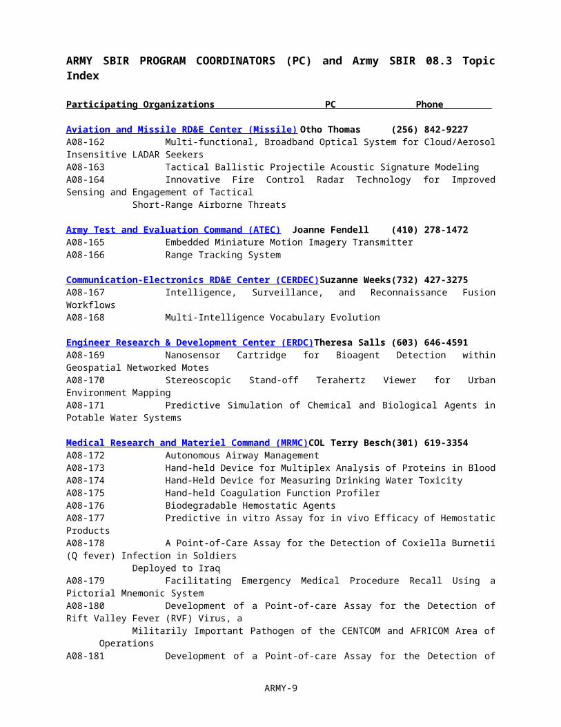
ARMY SBIR PROGRAM COORDINATORS (PC) and Army SBIR 08.3 Topic Index
Participating Organizations PC Phone
Aviation and Missile RD&E Center (Missile) Otho Thomas (256) 842-9227A08-162 Multi-functional, Broadband Optical System for Cloud/Aerosol Insensitive LADAR SeekersA08-163 Tactical Ballistic Projectile Acoustic Signature Modeling A08-164 Innovative Fire Control Radar Technology for Improved Sensing and Engagement of Tactical
Short-Range Airborne Threats
Army Test and Evaluation Command (ATEC) Joanne Fendell (410) 278-1472A08-165 Embedded Miniature Motion Imagery TransmitterA08-166 Range Tracking System
Communication-Electronics RD&E Center (CERDEC) Suzanne Weeks (732) 427-3275A08-167 Intelligence, Surveillance, and Reconnaissance Fusion WorkflowsA08-168 Multi-Intelligence Vocabulary Evolution
Engineer Research & Development Center (ERDC) Theresa Salls (603) 646-4591A08-169 Nanosensor Cartridge for Bioagent Detection within Geospatial Networked Motes A08-170 Stereoscopic Stand-off Terahertz Viewer for Urban Environment MappingA08-171 Predictive Simulation of Chemical and Biological Agents in Potable Water Systems
Medical Research and Materiel Command (MRMC) COL Terry Besch (301) 619-3354A08-172 Autonomous Airway ManagementA08-173 Hand-held Device for Multiplex Analysis of Proteins in BloodA08-174 Hand-Held Device for Measuring Drinking Water ToxicityA08-175 Hand-held Coagulation Function ProfilerA08-176 Biodegradable Hemostatic AgentsA08-177 Predictive in vitro Assay for in vivo Efficacy of Hemostatic ProductsA08-178 A Point-of-Care Assay for the Detection of Coxiella Burnetii (Q fever) Infection in Soldiers
Deployed to IraqA08-179 Facilitating Emergency Medical Procedure Recall Using a Pictorial Mnemonic System A08-180 Development of a Point-of-care Assay for the Detection of Rift Valley Fever (RVF) Virus, a
Militarily Important Pathogen of the CENTCOM and AFRICOM Area of OperationsA08-181 Development of a Point-of-care Assay for the Detection of Crimean-Congo Haemorrhagic Fever
(CCHF) Virus, a Militarily Important Pathogen of the CENTCOM, EUCOM and AFRICOM Area of Operations
A08-182 Development of a Point-of-care Assay for the Detection of Sand Fly Fever Virus (SFFV), a Militarily Important Pathogen of the CENTCOM, EUCOM and AFRICOM Area of Operations
Natick Soldier Research, Development & Engineering Gerald Raisanen (508) 233-4223Center (NSRDEC)A08-183 Cosmetic coating to protect unclothed skin from thermal (burn) injuryA08-184 Super-oleophobic/hydrophobic Coatings for Non-stick, Self-Cleaning TextilesA08-185 Greywater Recycling System for Mobile Kitchens and Sanitation CentersA08-186 Improving Representation of Situational Awareness in Constructive Combat SimulationsA08-187 Flameless Combustion for Kitchen AppliancesA08-188 Novel Textile Constructions for Puncture Resistant Inflatable CompositesA08-189 Digital Printing With Near Infrared Reflectance Properties for Rapid Deployment of Region A08-190 Light Weight Fabric for Parachute ModelingA08-191 Rapid Initialization for Personnel NavigationA08-192 Rapid Food Waste Remediation for Field Kitchens and Base CampsA08-193 Field Waste to Energy Conversion via Plasma Processing
Program Executive Office Command, Control, and Grace Xiang (732) 427-0284Communications Tactical (PEO C3T)A08-194 60 GHZ Wide Band, Local Radio (WBLR)
ARMY-6
Program Executive Office Missiles and Space George Burruss (256) 313-3523 (PEO MS) Rod Summers (256) 313-1049A08-195 Frequency Based Semi-Active Laser TrackingA08-196 Inertial Measurement Unit with Distributed Packaging
PEO Soldier King Dixon (703) 704-3309Jason Regnier (703) 704-1469
A08-197 Advanced Articulated Soldier Knee and Elbow Protection System
Single Integrated Air Picture Joint Programs Office Windy Joy Majumdar (703) 602-8021(SIAP JPO)A08-198 Feature Aided Tracking (FAT)A08-199 Distributed Resource Management (DRM)
Simulation and Training Technology Center (STTC) Thao Pham (407) 384-5460A08-200 Absolute Attitude and Heading Reference Measurement SystemA08-201 Unit Casualty Extraction Trainer
Tank Automotive RD&E Center (TARDEC) Jim Mainero (586) 574-8646Martin Novak (586) 574-8730
A08-202 LABORATORY TESTING PROCEDURES FOR CHARACTERIZING THE ARMORMATERIALS AND STRUCTURES DUE TO BLAST LOADING
A08-203 Semi-Autonomous Module for Robotic Door OpeningA08-204 Multi-Robot Pursuit System
ARMY-7
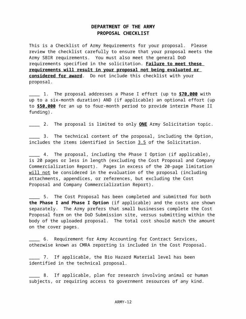
DEPARTMENT OF THE ARMYPROPOSAL CHECKLIST
This is a Checklist of Army Requirements for your proposal. Please review the checklist carefully to ensure that your proposal meets the Army SBIR requirements. You must also meet the general DoD requirements specified in the solicitation. Failure to meet these requirements will result in your proposal not being evaluated or considered for award. Do not include this checklist with your proposal.
____ 1. The proposal addresses a Phase I effort (up to $70,000 with up to a six-month duration) AND (if applicable) an optional effort (up to $50,000 for an up to four-month period to provide interim Phase II funding).
____ 2. The proposal is limited to only ONE Army Solicitation topic.
____ 3. The technical content of the proposal, including the Option, includes the items identified in Section 3.5 of the Solicitation.
____ 4. The proposal, including the Phase I Option (if applicable), is 20 pages or less in length (excluding the Cost Proposal and Company Commercialization Report). Pages in excess of the 20-page limitation will not be considered in the evaluation of the proposal (including attachments, appendices, or references, but excluding the Cost Proposal and Company Commercialization Report).
____ 5. The Cost Proposal has been completed and submitted for both the Phase I and Phase I Option (if applicable) and the costs are shown separately. The Army prefers that small businesses complete the Cost Proposal form on the DoD Submission site, versus submitting within the body of the uploaded proposal. The total cost should match the amount on the cover pages.
____ 6. Requirement for Army Accounting for Contract Services, otherwise known as CMRA reporting is included in the Cost Proposal.
____ 7. If applicable, the Bio Hazard Material level has been identified in the technical proposal.
____ 8. If applicable, plan for research involving animal or human subjects, or requiring access to government resources of any kind.
____ 9. The Phase I Proposal describes the "vision" or "end-state" of the research and the most likely strategy or path for transition of the SBIR project from research to an operational capability that satisfies one or more Army operational or technical requirements in a new or existing system, larger research program, or as a stand-alone product or service.
____ 10. If applicable, Foreign Nationals are identified in the proposal. An employee must have an H-1B Visa to work on a DoD contract.
ARMY-8
Army SBIR 083 Topic Descriptions
A08-162 TITLE: Multi-functional, Broadband Optical System for Cloud/Aerosol Insensitive LADARSeekers
TECHNOLOGY AREAS: Electronics
ACQUISITION PROGRAM: PEO Missiles and Space
The technology within this topic is restricted under the International Traffic in Arms Regulation (ITAR), which controls the export and import of defense-related material and services. Offerors must disclose any proposed use of foreign nationals, their country of origin, and what tasks each would accomplish in the statement of work in accordance with section 3.5.b.(7) of the solicitation.
OBJECTIVE: The objective of this topic is to develop a multi-functional, broadband optical system (BOS) for a cloud/aerosol insensitive LADAR seeker or IR Imager that can be utilized for tracking and identifying targets in the most adverse atmospheric conditions (including haze, standard fog, standard clouds, standard rain, standard snow, and artificial smokes/aerosols). The BOS should be capable of detecting targets at a distance greater than 7 kilometers in standard fog, cloud, and artificial smoke; greater than 16 kilometers in haze; and compatible with conventional LADAR detection schemes for standard and heavy rain and snow. The BOS should be capable of detecting targets with a 30 centimeter resolution and visualizing spectral signatures within the range of 0.5 microns to 20 microns.
DESCRIPTION: LADAR seekers play an irreplaceable role in tracking moving targets. However, conventional LADAR seekers use an optical wavelength around 1 micrometer or less (operated in visible or near IR regime), resulting in atmospheric attenuated signals due to dense clouds, fog, and/or aerosols in battlefield environments. In addition, only the geometric information of the targets is obtained; making it difficult to distinguish similar shape targets of various materials. Light attenuation in the atmosphere is mainly due to atmospheric absorption and scattering due to atmospheric particulates. When the light wavelength is substantially larger than the dimension of the scatterers (e.g., water droplet, dust), the attenuation is much smaller (less scattering effect). Atmospheric absorption is alleviated by excellent IR transmission windows currently existing in various wavelength ranges (e.g., 2-2.5 micron, 3-5 micron, 8–14 micron), as illustrated in Ref. 1. Scattering loss determines the atmospheric visibility and is highly wavelength dependent. The longer wavelength has significantly lower scattering loss. Mid-wave IR (MWIR) (extending from 3 to 5 microns) spectral band offers a potential method to minimize scattering loss because it is operable within the low loss atmospheric window and capable of penetrating aerosols and fog due to the longer wavelengths (as compared to visible and near IR). The drawback to using MWIR is the attenuation of the signal over multiple kilometers in the most adverse atmospheric conditions (as defined in the objective). Long Wavelength Infrared (LWIR) (extending from 8 to 14 microns) is another potential method to minimize scattering loss due to its propagation and transmission advantages in low visibility environments. LWIR is not a suitable choice for missile guidance and target recognition applications due to the use of a high power laser, which is heavy and expensive and will consume a large percentage of the missile’s power budget. A Broadband Optical System (BOS) would include multiple wavelengths (near, middle, and long wavelengths) and have advantages over the single narrow band near IR source due to reduced scattering of light when the wavelength is substantially larger than the dimension of the scattered particles (e.g., water droplet, dust). Also, recent advancements in the multiple wavelength broadband IR sources offers the possibility to provide IR sources the capability to extend transmission in low visibility conditions without the use of bulky and expensive high power lasers [2]. The BOS should be capable of detecting targets at a distance greater than 7 kilometers in standard fog, cloud, and artificial smoke; greater than 16 kilometers in haze; and compatible with conventional LADAR detection schemes for standard and heavy rain and snow. In addition, a BOS provides the unique capability to provide not only the geometric shape information of the targets but also the spectral signatures of the targets with resolutions comparable to the conventional LADAR. The additional spectral information can be an asset for target recognition systems to distinguish between real targets and camouflage. The advancement in technology of single and/or a broadband optical systems and MWIR sources and detectors in recent years, has resulted in the feasibility of developing a low cost, light weight, small footprint, eyesafe, broadband LADAR that covers both near IR, MWIR, and LWIR regime [3] . This advancement in LADAR technology represents a breakthrough for military applications by offering both the enhanced cloud/aerosol penetration capability and the spectral signatures of the targets.
ARMY-9

PHASE I: Conduct a detailed design and feasibility study on a multi-functional broadband optical system for a LADAR seeker that meets the specifications above. This study should include (1) the types of sources and the detectors to be used, (2) the optical system design, and (3) expected performances of the system, and (4) an evaluation of the cost, weight, and size of the design.
PHASE II: Based on the detailed design of Phase I, a prototype broadband optical system for a LADAR seeker should be fabricated and demonstrated during the Phase II stage. The performance of the prototype should be quantitatively tested and characterized. The evaluation data will be used to refine the initial prototype and improve its performance.
PHASE III: The technology developed under this Small Business Innovative Research can be used in various military applications such as, highly efficient LADAR seekers or IR Imagers used for missiles and UAVs. Civilian applications include free space optical communications, environmental pollution monitoring by remotely detecting hazardous chemicals in the atmospheres, and tracking or observing objects through smoke and fire conditions. REFERENCES: 1. E. Cure, C. Veret, “Transmission by haze and fog in the spectral region 0.35 to 10 microns,” Journal of Optical Society of America, Vol. 47, p. 491, 1957.
2. P.S. Westbrook, J.W. Nicholson, K. S. Feder, and A. D. Yablon, “Improved supercontinuum generation through UV processing of highly nonlinear fibers,” J. Light. Tech. 23, 13-18 (2005).
3. K.P. Hansen, R.E. Kristiansen, “Supercontinuum generation in photonic crystal fibers: Application note,” Crystal Fibre, Inc.
4. L. Andres, R. Phillip, “Laser beam propagation through random media (SPIE Optical Engineering Press, Bellingham, MA 1998).
5. R.M. Measures, Lasing Remote Sensing (John Wiley and Sons, New York, 1984).
6. N. Prasad, “Optical communications in the mid-wave IR spectral band, “Optical and Fiber communications Reports,” pp.558-602 (2005).
7. P.B. Ruffin, “Optical MEMS-Based Arrays,” SPIE, Smart Electronics, MEMS, BIOMEMS, and Electronics, Vol. 5055-3, p. 230, 2003.
KEYWORDS: Broadband Optical System, LADAR Seeker, MWIR, Near IR, IR Imager.
A08-163 TITLE: Tactical Ballistic Projectile Acoustic Signature Modeling
TECHNOLOGY AREAS: Ground/Sea Vehicles, Weapons
ACQUISITION PROGRAM: PEO Missiles and Space
The technology within this topic is restricted under the International Traffic in Arms Regulation (ITAR), which controls the export and import of defense-related material and services. Offerors must disclose any proposed use of foreign nationals, their country of origin, and what tasks each would accomplish in the statement of work in accordance with section 3.5.b.(7) of the solicitation.
OBJECTIVE: To develop the methodology for the analytical prediction of the acoustic signatures of incoming tactical munitions flying near ballistic trajectories.
DESCRIPTION: One of the more vexing problems remaining for the modern warfighter is self protection against traditional tactical projectiles - artillery, mortar, free flight rockets - flying essentially ballistic trajectories. Although various counter fire interception schemes have been devised, it is highly unrealistic, not to mention inefficient, to
ARMY-10

demand interception of each and every incoming round. Rather sophisticated techniques are required to selectively distinguish and intercept only those projectiles with a high probability of lethal impact. To do so, however, necessitates that techniques be devised for the detection/interrogation of incoming projectiles coupled to algorithms for ballistic trajectory prediction. Furthermore, it is most desirable, from a survivability standpoint, to maximize intercept ranges adding the additional burden that detection/interrogation/prediction be fast as well as accurate.
It is speculated that traditional techniques for range and direction determination in the electromagnetic wave spectra - ultraviolet, visible, infrared, millimeter wave, and microwave - might be augmented to meet this particular challenge with the addition of acoustic wave data. The assumption here is that the acoustic signature from incoming projectiles can be used as a discriminate for typing, i.e., artillery vs. rocket, for direction finding and range, and may help account for wind and other local weather effects on impact point predictions.
To use acoustic wave data for this purpose, however, requires that a first principles physics based model exist to characterize and exploit the phenomena for self protection. State-of-the-art computational fluid dynamics models and aero-acoustic models could serve as the foundation to build a reliable, high-fidelity predictive tool. Capabilities exist to account for the time-dependent prediction of projectile aerodynamics; however an acoustics driver must be added to feed the aero-acoustics or external wave propagation model. Methodology for propagation of the acoustic waves is in hand but the application of this methodology is in its infancy. Hence, this effort will focus on the initial step in comprehensive model development, namely acoustic signature prediction for incoming tactical ballistic projectiles.
PHASE I: Phase I proposals must demonstrate: (1) a thorough understanding of the Topic area, (2) technical comprehension of key fluid dynamic and acoustic wave propagation problem areas, and (3) previous experience in computational fluid dynamics and aero-acoustics. Technical approaches will be formulated in Phase I to address each of the key problem areas for inclusion into a prototype model for the prediction of acoustic signatures from incoming tactical ballistic projectiles. If proven feasible, at least one innovative, meaningful numerical demonstration will be proposed and run with the computational model during Phase I to assess the potential for Phase II success.
PHASE II: Additional model improvements formulated in Phase I, for example an atmospheric effects submodel, will be finalized, documented, coded, and incorporated into the prototype model. The improved model will then be used to help formulate and conduct a Government run validation test for the methodology. PHASE III: If successful, the end result of this Phase-I/Phase-II research effort will be a validated model for the analytical prediction of the acoustic signatures of incoming tactical munitions flying near ballistic trajectories. The transition of this product, a validated research tool, to an operational capability will require integration, with possible simplification, of the software product into a weapon system.
This technology has direct military application for self defense against artillery, mortar, and free flight rocket attack. The most likely customer and source of Government funding for Phase-III will be those service project offices responsible for the development of anti-RAM missile and/or gun systems. For commercial applications, this technology is directly applicable to advanced warning systems such as airport, automotive, and railway traffic control and crash avoidance. REFERENCES: 1. Hixon, R. and Turkel, E., "High-Accuracy Compact MacCormak-type Schemes for Computational Aeroacoustics," AIAA Aerospace Sciences Meeting and Exhibit, 13-15 Jan 1998, Paper No. AIAA-98-0365.
2. Tam, C., "Advances in Numerical Boundary Conditions for Computational Aeroacoustics," AIAA Computational Fluid Dynamics Conference, 29 Jun-2 Jul 1997, Paper No. AIAA-97-1774.
3. Goodrich, J., "High Accuracy Finite Difference Algorithms for Computational Aeroacoustics," AIAA Aeroacoustics Conference, 14-14 May 1997, Paper No. AIAA-97-1584.
KEYWORDS: aero-acoustics, discrimination, detection, ballistic projectiles, self defense
ARMY-11
A08-164 TITLE: Innovative Fire Control Radar Technology for Improved Sensing and Engagement ofTactical Short-Range Airborne Threats
TECHNOLOGY AREAS: Sensors, Weapons
ACQUISITION PROGRAM: PEO Missiles and Space
The technology within this topic is restricted under the International Traffic in Arms Regulation (ITAR), which controls the export and import of defense-related material and services. Offerors must disclose any proposed use of foreign nationals, their country of origin, and what tasks each would accomplish in the statement of work in accordance with section 3.5.b.(7) of the solicitation.
OBJECTIVE: To design, build and demonstrate an innovative fire control radar technology that improves tactical short-range airborne target sensing performance and, when integrated with a missile, improves engagement performance against tactical ballistic threats compared with the performance of conventional fire control radars.
DESCRIPTION: The U.S. Army is engaged in programs to negate the effects of short-range tactical ballistic threats such as rockets, artillery, and mortars (RAM) and guided threats such as surface-to-air missiles and precision guided artillery rounds. Many of these threats have short times of flight requiring early detection and track and due to the ability to use saturation threat quantities there is a need to provide multiple simultaneous target servicing. For the engagement process radar technology is required to provide fire control for missile interceptors and accurate impact point prediction for efficient target-weapon assignment. Since there will likely be multiple shooters per battle element there may be a need for multiple radars to support fire control over the entire battlefield. There is a need to develop an innovative radar technology that will perform target detection, track, and engagement support across a large and cluttered battlefield environment in order to enhance the operational deployment capability of proposed weapons and sensors for the RAM sense, warn, respond, and engage mission. The innovative radar technology will likely utilize waveform diversity in order to operate in a limited available RF spectrum. Proposed radar technologies should demonstrate improvements in detection, tracking, and interceptor support over conventional radar concepts in use today without significant increase in cost. This unique radar technology will provide significant improvements in track accuracy and target servicing rate for fire control radars that has capability well beyond surveillance radars such as Low-cost Counter-Mortar Radar (LMCR).
For purposes of design, the radar technology will be required to acquire RAM threats out to 10 km slant range, support RAM engagements out to 5 km slant range, and enable engagement of multiple threats. The radar targets include small-medium caliber rockets and mortars that impose both low and high elevation detection and tracking requirements. In addition the radar technology should be able to determine accurately the launch point and the impact point of threat trajectories. The radar shall be required to support command and semi-active guided missile interceptors. Growth to longer range should also be addressed. Radar size and cost should be a design concern. Cost-effective and innovative technologies in waveform diversity, signal processing, and antenna architectures that utilize limited RF spectrum should be emphasized while power-aperture should be constrained.
PHASE I: Develop an innovative radar design and antenna architecture and conduct a proof-of-concept simulation that will demonstrate improved performance of the sense, warn, respond, and intercept missions for short-range airborne target threats. The simulation should show the advantages of the proposed radar technology over conventional radar technologies. The proposed radar design should be able to service multiple simultaneous targets including low elevation rocket threats.
PHASE II: Build and demonstrate a prototype radar that will clearly show the potential of the technology to improve the performance of the sense, warn, respond, and intercept missions for short-range target threats. Demonstrate multiple target handling and compare launch point estimation and impact point prediction accuracy to conventional radar technologies.
PHASE III DUAL USE COMMERCIALIZATION: Technology developed under this topic will both improve the operational performance of existing radar systems through reduced power consumption but also provide a platform for revolutionary new capabilities through better angle/range resolution resulting in better target acquisition and tracking. This capability is being developed in parallel with the Extended Area Protection and Survivability (EAPS) ATO program to provide for high target servicing rates. EAPS is currently being developed by industry and is
ARMY-12
scheduled to transition to full scale development. The private sector will also be able to benefit from this technology to improve communications and tracking technologies to potentially benefit such industries as air-traffic control, marine navigation, and cell-phone position location.
REFERENCES:1. M. I. Skolnik, Radar Handbook, McGraw-Hill, New York, 1970.
2. F. E. Nathanson, Radar Design Principles, SciTech Publishing, Inc. Mendham, NJ, 1999.
3. P. Zarchan, Tactical and Strategic Missile Guidance, AIAA, Inc. Washington DC, 1994.
4. P. Garnell, Guided Weapon and Control Systems, Pergamon Press, Oxford UK, 1980.
5. N. J. Willis, Bistatic Radar, SciTech Publishing Inc., Raleigh, NC, 2005.
6. S. D. Blunt and K. Gerlach, Adaptive Radar Pulse Compression, 205 NRL Review, Naval Research Laboratory, 2005.
7. G. M. M. Siouris, Airborne Missile Guidance and Control Systems, Springer-Verlag LLC, New York, NY, 2004.
8. E. J. Holder, R. Smith, and M. Shipman, Interferometric Acquisition and Fire Control Radar for SWORD, 47th Tri-Service Radar Symposium, 2001.
KEYWORDS: Radar, Signal Processing, Waveform Diversity, Surveillance, Target Tracking, Fire Control, Missile Guidance, Command Guidance, Semi-Active Guidance, Ballistic Targets
A08-165 TITLE: Embedded Miniature Motion Imagery Transmitter
TECHNOLOGY AREAS: Electronics
The technology within this topic is restricted under the International Traffic in Arms Regulation (ITAR), which controls the export and import of defense-related material and services. Offerors must disclose any proposed use of foreign nationals, their country of origin, and what tasks each would accomplish in the statement of work in accordance with section 3.5.b.(7) of the solicitation.
OBJECTIVE: The objective of this topic is to develop an Embedded Miniature Motion Imagery Transmitter (EMMIT). The transmitter requires high speed DSP/FPGA or other, high performance; low power consumption embedded electronics that can accommodate low-latency compression, accurate frame time-stamping, provide remote configurability and support the transmission of raw or compressed digital and analog formatted video signals. The effort will require the development a mechanism for efficiently time-stamping, compressing and transmitting non-standard video protocols within a tightly constrained physical space. The device must accommodate digital video formats utilized in the scientific, military and factory floor environments including CameraLink, and GigaBitEthernet. The device must support high speed visible and Infrared Imaging Systems that utilize large format, high pixel bit-depth sensors. The system must support the ability to remotely configure the imaging systems on the fly and support real-time changing of the camera framerate, and other imaging system parameters. The system must incorporate innovative compression methods such as floating graded foviation to accommodative low bandwidth wireless transmission systems. The system must be flexible to allow GPS or IRIG based time-stamping to be turned on/off remotely. The capability should allow a standard receiver to view the motion video imagery with the system adding less than 100ms for compression and transmissions operations.
DESCRIPTION: NEED: DoD and Homeland Security communities are transitioning from analog video to digital technologies that have significant improvements in frame rate, resolution, pixel depth, high dynamic range, infrared wavelengths, and windowed readouts. The need for low-latency, highly efficient digital streaming systems to support these technologies are required to allow remote man-in-the-loop operators to view and control the imaging systems.
ARMY-13
One example of this need in the DoD Test and Evaluation Community exists at White Sands Missile Range (WSMR). WSMR has developed the FCS (Future Combat Systems) Integrated Remote Enabled Camera Management (FIRECAM) system for distributing digital formatted video. ATEC is utilizing the capability to support FCS testing and training exercises by allowing test conductors and observers to remotely view operations and remotely control the imaging systems. The capability would be greatly augmented with the addition of an embedded miniature motion imagery compressor and transmitter for real-time operations. Current FIRECAM front end compression / transmission systems that perform the operations necessary to support the digital imaging technologies are based on full-size rack mount computer systems. The EMMIT will be hand-held in size and allow for mounting on remote towers, inside buildings and small areas and on vehicles. Because of the highly integrated, small footprint capability, the EMMIT device will readily lend itself to harsh and challenging environments where there currently is no mechanism for transmitting the types of sensor data that the EMMIT will be designed to handle.
CURRENT TECHNOLOGY: The DoD community is currently utilizing and expanding the use of Infrared and high capability machine vision digital imaging sensors to satisfy intelligence and test data collection needs. The imaging systems are superior in the areas of size, cost, resolution, bit-depths, and sensitivity and frame rates as compared with the commercial broadcast market. The digital imagers utilize standardized interfaces including CameraLink and Gigabit Ethernet. These systems are capable of generating data rates in excess of a GigaByte per second (GB/s) with an ever increasing trend. To perform the necessary smart compression, bandwidth optimization, time-stamping and low latency transmission required to move this data over network systems currently requires rack-mount and in some cases lower performing PC-104 based systems. A variety of techniques are currently utilized to time-stamp the imagery, extend the CameraLink data over fiber and inject it into a framegrabber for processing. A compact, low power, high-performance compression and low-latency transmission system does not exist that can accommodate the real-time streaming of these systems.
SOLUTION NEEDED: The EMMIT must provide a rugged, compact, low-cost, low latency, and high performance embedded video system that will allow nonstandard video to be accurately time-stamped and transmitted via standard video formats and protocols. The EMMIT must fully support the CameraLink standard in order to allow remote control of the imaging systems from the remote operator / viewer locations.
The EMMIT should leverage existing commercial standards where possible, such as H.264, VC-1 and JPEG2000 video codecs, CameraLink and Ethernet interfaces, and be DoD Motion Imagery Standards Profile (MISP) compliant. The MISP compliance will allow the EMMIT to plug and play with existing DoD end equipment and provide a drop-in capability for remote motion imagery applications ranging from static surveillance to targeting applications on an unmanned vehicle.
At the Test Ranges, the EMMIT system can be fielded in large numbers to allow for a significant improvement over the current capability of only viewing motion imagery from a few select locations at any one time. In addition, the ability to leverage high bit depths, high resolutions, and infrared wavelengths, will allow the end user to see phenomena in real-time that is currently not possible. With large format sensors, additional capabilities can be added to format the image before it is transmitted for remote display. With a large field of pixels, a technique referred to as graded foviation, which mimics the operation of the human retina, can be used to convert a standard uniform resolution image to a multi-resolution format. The benefit of this technique is an intelligent, targeted lowering of the required bit rate to send the image. A portion of the research on this topic will be dedicated to defining appropriate mechanisms for efficiently scaling, formatting, pruning, and binning a video signal based on the scene content and the make-up of its entropy within the stream.
High resolution sensors can also be configured with zoom lenses to provide tremendous overall zoom ranges that don’t suffer from the loss of resolution that current commercial digital zoom systems have. These types of features will significantly increase the level of situational awareness and provide test operators and flight safety officers with a reduced burden when trying to make critical real-time decisions.
A comprehensive solution to this topic will address two high risk areas of research: hardware and methodology development. The hardware solution will require an efficient and innovative architecture that will allow for the capture of multiple video types, automatically detect the video format present, prepare the video for optimum information coding, time stamp the imagery when the option is selected and then compress, wrap, and transmit the video to remote users. Systems with a limited portion of the described capabilities have been implemented in rackmount PCs. It is desired that the EMMIT system be physically configured to be about the size of a few decks of
ARMY-14
cards. The methodology solution will focus on designing a framework and interface for removing the traditional barriers of resolution, bit-depth, and frame rate constraints and allowing a user to configure and manipulate a system for best capturing the type of information required given a fixed and constrained bandwidth pipe for transmission.
BACKGROUND: White Sands Missile Range has developed the FCS Integrated Remote Enabled Camera Management system (FIRECAM) for the purpose of transmitting motion imagery to remote locations. The EMMIT system will provide a required capability for the FIRECAM system by allowing small, light weight transmission systems to be mounted at remote unattended locations such as towers, and in locations without firm power such as in remotely operated vehicles. This capability will significantly enhance the level of situational awareness during an exercise or test for Future Combat Systems and any other program that is testing on the Range.
PHASE I: The investigator shall conduct a feasibility study to research and develop an Embedded Miniature Motion Imagery Transmitter design. The investigator will determine the best solution to meet the shortfall for transmitting multi-resolution, multi-bit-depth motion imagery to remote locations. The system shall be compliant with the latest version of the DoD Motion Imagery Standards Profile (MISP). The analysis and research shall provide the basis for a full-scale prototype design using the latest in high speed, low power, and compact electronic components. Compression algorithms and bandwidth reduction techniques most compatible with the embedded design will be investigated.
PHASE II: The investigator shall proceed with a prototype development and demonstration of the technology proposed in Phase I. The full-scale prototype Embedded Miniature Motion Imagery Transmitter will be fabricated, tested, and evaluated to determine if requirements were met. Estimates for Phase III pre-production costs and revisions to the design (based on test results) will be developed.
PHASE III: The Embedded Miniature Motion Imagery Transmitter is an innovative design that will readily adapt to numerous commercial industry and Government applications. Commercialization will benefit DOD for numerous remote motion imagery applications and scenarios. This system can be used in a broad range of military and civilian security applications where automatic surveillance and tracking are necessary – for example, in remote perimeter and early warning defense surveillance, unmanned vehicle operation, overseas peacekeeping operations, enhancing security in industrial facilities, aviation tracking, and border patrol surveillance. The EMMIT could potentially be used for providing targeting data to military defense weapon systems. Additional units purchased will depend on operational test results and durability in the field.
The customer for the initial EMMIT capability is the White Sands Missile Range (WSMR). WSMR will utilize and test the system in support of a variety of active missions. WSMR will request on-going program funding in the Army's Development Test Command (DTC) Technology Development and Acquisition Program (TDAP) system to implement the EMMIT capability.
REFERENCES:1. MISB MISP 4.1, Motion Imagery Standards Profile, 14 December 2006.
2. SMPTE 336M-2001, Data Encoding Protocol Using Key-Length-Value.
3. SMPTE RP210.8-2004, Metadata Dictionary.
4. MISB RP 0102.2, Security Metadata Sets for Digital Motion Imagery, 20 November 2003.
5. MISB RP 0103.1, Timing Reconciliation Metadata Set for Digital Motion Imagery, 11 October 2001.
6. MISB RP 0107, Bit and Byte Order for Metadata in Motion Imagery Files and Streams, 11 October, 2001.
KEYWORDS: MISP, H.264, streaming video, embedded systems, CameraLink, GigE Vision, Infrared, DSP/FPGA, Intelligent, Graded Foviation, compression
A08-166 TITLE: Range Tracking System
ARMY-15
TECHNOLOGY AREAS: Electronics
The technology within this topic is restricted under the International Traffic in Arms Regulation (ITAR), which controls the export and import of defense-related material and services. Offerors must disclose any proposed use of foreign nationals, their country of origin, and what tasks each would accomplish in the statement of work in accordance with section 3.5.b.(7) of the solicitation.
OBJECTIVE: Design and develop a mobile tracking system capable of tracking and providing real-time Time Space Position Information (TSPI) for small missiles, rockets, aircraft, and unmanned aerial systems that has a capability to track projectiles at low angles that current radar-based tracking systems lack. This system shall be capable of operating on test and evaluation (T&E) ranges across the country. The system shall operate in the same environmental conditions (temperature, humidity, precipitation, wind, etc.) that weapon systems will see. Ideally, the system will be small enough to allow it to be mounted on unmanned aerial vehicles (UAV) and unattended ground sensors (UGS) to allow the system's utility to be expanded beyond the test range to feed information to battle command systems.
DESCRIPTION: One of the primary data elements collected on test and evaluation ranges across the country is TSPI data. Having air vehicles approach a target at low altitude and a fairly flat or level trajectory is a way of defeating detection by radar. This is why the phrase "under the radar" has entered our language. Current radar-based TSPI instrumentation is unable to extract azimuth and elevation data for projectiles that are traveling at low angles to the horizon because of multi-path effects due to reflection from the ground or background. Current Doppler radar systems cannot track slow moving objects reliably.
Current laser tracking systems require target modification to increase reflectivity sufficiently to track the target. A laser tracking system developed using current technology could be developed to track unmodified targets, thus increasing the number of types of objects a laser tracker can track. Additional target categories that cannot be tracked reliably with radar-based TSPI systems include super-sonic or possibly hyper-sonic targets that cannot be tracked with existing laser tracking technology because the reflective modifications are destroyed by the frictional heat generated.
Due to the selection of wavelengths of modern lasers available, a modern laser tracking system could track objects that are considered “stealth” that are invisible to radar but do reflect other wavelengths, including, but not limited to, some visible wavelengths. Optical-based TSPI instruments cannot provide accurate range information. A laser tracking solution does not have these shortcomings and a current technology solution is required.
A secondary, but still important, consideration is the fact that many if not all existing laser based tracking system used for missile and rocket testing were developed ten to twenty years ago and are beyond their useful lives because replacement parts are either unavailable, uneconomical or have to be custom made. They also do not provide the information required to support testing, or have the data storage capacity required by current test plans. Failure of these systems increases the cost of testing because information is not collected, and additional trials have to be run. Current radar-based TSPI instrumentation is unable to extract azimuth and elevation data for projectiles that are traveling at low angles to the horizon because of multi-path effects. Optical-based TSPI instruments cannot provide accurate range information. A laser tracking solution does not have these shortcomings and an advanced technology solution is required.
PHASE I: Develop overall system design for a laser based tracking system capable of providing highly accurate TSPI data for small missiles, rockets, aircraft, and unmanned aerial systems. This system will need to be integrated into existing and future battle command systems. An advanced technology solution that has an open architecture is required to support future changes to range instrumentation and C4ISR requirements to battle command. The system should be economically designed, fabricated, operated and maintained.
PHASE II: Develop and demonstrate a prototype range tracking system in a realistic environment. Conduct testing to prove feasibility over extended operating conditions.
PHASE III: This system could be used in a broad range of military and civilian applications where object tracking is necessary and radar solutions are restricted due to spectrum allocation, one of which is air traffic control in both the civilian and military sectors. This system could be used with UAVs and UGS to support battle command.
ARMY-16

REFERENCES: None.
KEYWORDS: Sensors, tracking, position, situational awareness, flight testing, guided missiles, test and evaluation, TSPI (Time, Space, and Position Information), laser tracking, position information, battle command
A08-167 TITLE: Intelligence, Surveillance, and Reconnaissance Fusion Workflows
TECHNOLOGY AREAS: Information Systems, Electronics
ACQUISITION PROGRAM: PEO Missiles and Space
OBJECTIVE: The objective of this effort is to research innovative technologies and methods to facilitate the establishment of operational workflows for intelligence, surveillance, and reconnaissance (ISR) data fusion. ISR fusion requires the ability to exchange and integrate information produced from a diverse, and often dynamic, set of sensors, in order to generate high-fidelity common operating pictures and to satisfy mission objectives. Warfighters need help leveraging these capabilities into ISR analysis workflows that support the TPPU (task, post, process and use) model [1]. The results of this research should be applicable to modern, net-centric ISR environments such as Distributed Common Ground Systems (DCGS) and the future Aerial Common Sensor (ACS) [2, 3, 4].
DESCRIPTION: Background: The objectives of this topic address a focused set of needs in support of Army Battlespace Awareness Force Operating Capabilities. Battlespace Awareness (BA) is an overarching, unifying concept mechanism to orchestrate and synchronize ISR operations across echelons, services, agencies and coalition partners, by enhancing collaboration, adding new capabilities, and in some cases, performing existing functions more efficiently and effectively [5]. Fusion is the critical technology that underpins these components and in many circles has become synonymous with BA functions. Fusion, by definition, is a series of processes to transform observable data into more detailed and refined information, knowledge and understanding. These processes involve a mixture of automation and human awareness and thinking.
The commander establishes information requirements based on mission, enemy, terrain and weather, troops and support, time and civil considerations (METT-TC). The fusion process, operating over integrated communications networks, includes accepting data from all ISR sources, organic and external. Sensors include: combat platforms and soldiers; organic manned and unmanned reconnaissance and surveillance platforms; and, external artifacts/groupings. Fusion ensures that a correlated, non-duplicative set of information is available across the force and provides context to the information that has been acquired to enable situational understanding. This requires that the data and information should be converted as quickly as possible into actionable intelligence.
Topic Focus: Fusion is accomplished within the context of a broader set of ISR activities. These include: the planning and direction of ISR assets; processing and exploitation of sensor data; analysis and production of intelligence products; and, the dissemination of data, information, and intelligence. Collectively, these activities form ISR workflows that organize the activities to accomplish the overall ISR mission. The complex nature of existing ISR workflows is typically characterized by minimal systems interoperability and manual processes that hinder timely fusion. This also can result in a fragmented view of the battlespace.
The challenge is to coordinate and manage the flow of intelligence products from diverse sensors as coherent activities in order to increase the quality and speed of engagement. A significant technical risk is in the orchestration of ISR workflows in near real-time with large, heterogeneous data sets. As a mitigation of this risk, a key technical focus of this effort will be the investigation of innovative technologies to represent and integrate ISR fusion workflows. The scope of this topic does not include the development of new ISR fusion algorithms but rather is limited to the design and eventual development of architectures that can be utilized to facilitate the composition of fusion algorithms to support analyst workflows. The Soft Target Exploitation and Fusion (STEF) Army Technology Objective (ATO), which seeks to produce actionable intelligence on individuals, is an example of a potential application area of this work.
ARMY-17
PHASE I: Develop a technical approach to facilitate innovative operational workflows, including requirements, usage scenarios and prototype architecture, for implementing effective ISR fusion workflows in net-centric environments. Establish the feasibility, including technical risks assessment, of the proposed approach.
PHASE II: Capture the specific operational scenarios within a government specified domain (such as Guardrail Common Sensor (GRCS) legacy systems). Develop a prototype to demonstrate the capability of the system for use by the Army. The architecture for the technology and how it fits into the target environment architecture will be defined. The phase II technology will be integrated in a lab or simulated environment with the characteristics of the target environment. Define and collect initial performance benchmarks to validate the technology.
PHASE III: The end state of this research is effective information analysis workflows being utilized by multiple organizations to achieve unprecedented collaboration and information throughput. Army applications include use of the technology by stakeholders in all stages of the ISR analysis workflow. Similar needs exist in the other services, homeland defense, and intelligence agencies, and phase III applications may involve cross-organization net-centric workflows. Candidate Army transition programs include ACS and DCGS-Army. Potential dual use would be the application of this technology in commercial organizations to improve the production of critical business intelligence about competitors, customers, suppliers, and new markets. Large financial institutions would rapidly embrace an automated workflow technology capable of consuming federated banking information to understand and analyze consumer trends. As a tangible commercialization example, pharmaceutical companies could leverage this technology to automate different business workflows (e.g. research, manufacturing and marketing) to expedite the discovery and the time to market for new drugs.
REFERENCES: 1. Dam, Steve, “DoD Architecture Framework: A Guide to Applying System Engineering to Develop Integrated Executable Architectures”, BookSurge Publishing, 2006.
2. Chizek, Judy, “Military Transformation: Intelligence, Surveillance and Reconnaissance,” Library of Congress, July 2003.
3. Dept. of Defense Chief Information Officer Memorandum, “DoD Net-Centric Data Strategy,” May 9, 2003.
4. Distributed Common Ground System – Army; http://www.monmouth.army.mil/peoiew/dcgsa/
5. U.S. Joint Chiefs of Staff. Functional Concept for Battlespace Awareness. Washington, D.C.: U.S. Joint Chiefs of Staff, 31 October 2003.
KEYWORDS: battlespace awareness; intelligence; intelligence, surveillance, and reconnaissance (ISR); workflow; system interoperability; net-centric warfare
A08-168 TITLE: Multi-Intelligence Vocabulary Evolution
TECHNOLOGY AREAS: Information Systems, Electronics, Human Systems
OBJECTIVE: The objective of this effort is to research/develop innovative automated and accessible shared vocabulary technologies/methodologies, to replace currently manual and labor intensive capabilities, that will enable Multi-Intelligence (Multi-INT) data asset discovery, retrieval, and fusion. Modern, net-centric environments will result in a profusion of the number, types, and sources, of data assets that are available to the military intelligence analyst. Multi-INT types include Signals Intelligence (SIGINT), Human Intelligence (HUMINT), Imagery Intelligence (IMINT), Geospatial Intelligence (GEOINT), and Measurement and Signatures Intelligence (MASINT). The challenge has shifted from getting access to information to one of finding relevant information in a tactically meaningful timeframe. The lack of a well-understood shared vocabulary hinders the analyst’s ability to find relevant information, and this problem will grow dramatically as the number of data sources continues to grow. Research is needed to investigate new potential solutions that can address the dual challenges of scalability and timeliness in the evolution of multi-intelligence vocabularies. The results of this research are applicable to Army
ARMY-18
Program such as the Distributed Common Ground Systems—Army (DCGS-A) and the Aerial Common Sensor (ACS) [1, 2].
DESCRIPTION: Background: The ability to share information to achieve Information Superiority is a crucial capability in the fulfillment of the vision for the Future Force (FF). To achieve the FF vision, knowledge management and fusion capabilities (FOC-02-05, FOC-02-06 [3]) together enable a ‘producer interactive network,’ in which force elements will be able to subscribe to products or data, including archival data. Domain specific data representations, shareable across multiple domains, will be available. In this manner, all force elements will be provided access to common data, enabling Joint, Allied, and Coalition warfighters to construct tailorable, relevant pictures.
Two of the DoD Net-Centric Data Strategy’s [3] key tenets specifically support this information sharing vision: (1) ‘tagging‘ of all data (intelligence, non-intelligence, raw and processed) with metadata to enable discovery by users; and, (2) posting of all data to shared spaces to provide access to all users. The Net-Centric Data Strategy also introduces management of data within Communities of Interest (COI) rather than the humongous task of standardizing data elements across the entire intelligence community. COI is the inclusive term that describes collaborative groups of users who must exchange information in pursuit of their shared goals and who therefore must have a shared vocabulary for the information they exchange [4].
TOPIC FOCUS: The focus of this topic is on Multi-INT vocabulary evolution in support of net-centric warfare. The process of developing a shared vocabulary to be used in the metadata tags encompasses two basic types of harmonization activities. First, harmonization of terminology is needed to describe, for example, concepts such as the types of data assets and their content. Second, harmonization of schemas is needed to achieve a common data representation in order to facilitate consumption of the data.
Current approaches to harmonization and vocabulary evolution rely on a human-in-the-loop. These manually intensive solutions can’t keep pace with the increasing number of INT sources combined with the need to fuse Multi-INT data. The challenges faced in vocabulary evolution are driven by both incremental changes to the vocabulary and more significant discrete events, such as introduction of a new sensor. In the latter scenario, currently the time to harmonize a new INT source is measured in months or more. This limits the value of the intelligence when it is most needed, such as in time-critical tactical missions in response to asymmetric threats.
Significant scalability risks for net-centric environments result from the inevitable evolution of a shared vocabulary while the vocabulary is in operational use, and from undesirable coupling among components at the data level. Whereas a service-oriented architecture style is intended to decouple the software components, producers and consumers of data asset are still coupled by their shared vocabulary embedded in the metadata and by common data representations. A vocabulary must evolve over time as new concepts emerge, for example, as a result of new types of sensor technologies or of unforeseen utilization of existing technologies. COI membership may change as well, and new members may not be familiar with the established vocabulary, making it difficult to discover and consume data assets.
The scope of this topic is focused on the metadata strategy, its implementation within a metadata catalog, and improving the agility of capabilities of discovery and retrieval services in the face of dynamic forces such as vocabulary evolution and ad-hoc COI formation. Two significant technical risks must be addressed before practically implementable solutions are achievable. The first risk is the scalability of potential solutions, which is magnified by the unique challenges of Multi-INT data discovery, retrieval and fusion (e.g., ability to handle increasing numbers of INT types and producers, increasing richness of the INT data, and increasing number of INT consumers). The second risk is the ability to accomplish the evolution of the vocabulary in tactically relevant (ideally real-time) timeframes. Solutions which rely upon or make only incremental improvements to current human-in-the-loop vocabulary evolution approaches are unlikely to adequately address or mitigate these risks.
Research into new and innovative approaches that overcome these risks is critical. Of particular interest are scalable, high-throughput approaches to Multi-INT vocabulary documentation and discovery, localization or personalization of vocabularies, dynamic vocabulary and data representation transformation, and vocabulary life cycle change management.
PHASE I: Research and develop the proposed technical approach, including technology innovations in the areas of evolution of operational vocabularies, requirements, usage scenarios and prototype architecture for improving Multi-
ARMY-19
INT data discovery and retrieval in net-centric environments. Establish the feasibility, including technical risks assessment, of the proposed approach.
PHASE II: Capture the specific operational scenarios for evolution of operational vocabularies to improve Multi-INT data discovery and retrieval within a government specified domain. Develop a prototype to demonstrate the capability of the system for use by the Army. The architecture for the technology and how it fits into the target environment architecture should be defined. The phase II technology will be integrated in a lab or simulated environment with the characteristics of the target environment. Define and collect initial performance benchmarks to validate the technology.
PHASE III: The end state of this research is enhanced vocabulary evolution capabilities utilized in a net-centric environment to achieve unprecedented agility and scalability in the sharing of Multi-INT data assets. Army applications include use of the capabilities by stakeholders in all stages of Multi-INT discovery, retrieval and analysis. The initial candidate Army transition program is DCGS-A. Additional Phase III applications are anticipated within the Intelligence Community to enable information sharing among multiple agencies, and in maritime domain awareness (e.g., port security) where military and law enforcement organizations have similar information sharing needs. Potential dual use would be the application of this technology in commercial organizations to improve the sharing of information by businesses with their supply chain, customers, and partners. For example, global electronic parts producers and consumers suffer from vocabulary dissonance in the way parts are categorized and decomposed. A typical approach to solving this problem is one of data cleansing of parts catalogs, but since this approach relies on a centralized data storage mechanism (such as a data warehouse), it is not suited to highly dynamic and distributed environments.
REFERENCES: 1. Distributed Common Ground System – Army. http://www.monmouth.army.mil/peoiew/dcgsa/
2. Rider, Timothy L., 'Having passed through stormy clouds, Army intelligence aircraft sets new course', Army.Mil News, Jan 29, 2008. http://www.army.mil/-news/2008/01/29/7180-having-passed-through-stormy-clouds-army-intelligence-aircraft-sets-new-course/
3. TRADOC Pam 525-66, 'Military Operations Force Operating Capabilities', July 2005.
4. Department of Defense Chief Information Officer Memorandum, 'DoD Net-Centric Data Strategy,' May 9, 2003. www.defenselink.mil/cio-nii/docs/Net-Centric-Data-Strategy-2003-05-092.pdf
5. Hohpe, Gregor and Bobby Woolf, 'Enterprise Integration Patterns', Addison Wesley, 2004.
KEYWORDS: vocabulary, Communities of Interest, metadata, information sharing, multi-intelligence, net-centric
A08-169 TITLE: Nanosensor Cartridge for Bioagent Detection within Geospatial Networked Motes
TECHNOLOGY AREAS: Chemical/Bio Defense, Sensors
OBJECTIVE: Development of a nanosensor based thin-film cartridge to aid in conjunction with a geospatial network to monitor biological threat agents on range soils and battlefields to support troop mobility.
DESCRIPTION: There is a need for near-real time detection (less than 5 minutes), quantification (trace quantities-depending on the biological agent(s) selected for testing), and location of biological threat agents in trace quantities given a release within the air column. There is also a need to spatially determine the extent of such a biological release and presence. To do this, distributed placement of the networked sensors is desired. Currently, self contained networked motes are being developed, but lack replacement cartridges for sensor recognition of biological threat agents. Nanosensor thin filmed cartridges are envisioned to handle the same environmental and self contained conditions of the networked motes. One such approach for developing the nanosensor thin films could include use of a synthetically designed polymeric matrix that would act as a sensor template wherein probes are adhered to the matrix for use in biological detection and sensor recognition. The thin filmed matrix may also be arrayed for various
ARMY-20
biological threat agents. A highly efficient matrix would be queried by an existing or improved V-cell LED-like chip and would be self contained within the networked motes to determine detection of bioagent(s). The bioagent probe embedded within the thin film, for example, could be fluorescent, but is not limited to fluorescent illuminated detection. The active site on the thin film matrix containing the adhered probes could also be in contact with enhancement (such as metal enhancement) for amplification of signals for improved sensitivity. The thin film would be part of a plug and play cartridge, which would be housed within the networked self contained motes. The motes would be subject to environmental air sampling conditions by being placed on the surface of soils within the terrain and interrogation for remote response and stability of the remotely placed sensor.
PHASE I: Complete a conceptual design and demonstrate feasibility of a nanosensor thin film matrix cartridge for biological threat agent detection. The concept design should include: the target bioagent simulants, the array design, if applicable, and the thin film matrix upon which the bioagent(s) are attached. As part of feasibility demonstration, it would be desirable to include tests of signal/probe preparations required for the detection of select bioagents and/or bioagent simulants. The conceptual design will also need to be integrated into an existing multi-mote based communications sensor that is currently being developed.
PHASE II: Develop and demonstrate prototype system and compatibility with existing multi-mote based communications sensor. Test under a range of controlled bioagent material concentration releases in the air under various realistic environmental conditions. Apply different analytical procedures for elucidating “harvested” tagged probes. Integrate global positioning with the unit for locating, time-stamping, and mapping detected bioagent releases. Time stamping should provide the needed information for monitoring bioagent transport and dispersal rates. This will be done in collaboration with existing networked motes.
PHASE III: Such a device has broad dual use applications from monitoring environmental air quality to expanded military uses including non-man portable range monitors. Additionally, drones may be adapted to distribute and monitor the chambers remotely.
REFERENCES: 1. Smith, C.B.*, Anderson, J.E., Fischer, R.L., and Webb, S.R. (2002) Stability of Green Fluorescent Protein using Luminescence Spectroscopy: Is GFP Applicable to Field Analysis of Contaminants? Environmental Pollution. Vol.120. No.3. p. 23-26.
2. Metal-Enhanced Fluorescence-Based RNA Sensing, Kadir Aslan, Jun Huang, Gerald M. Wilson, and Chris D. Geddes, J. Am. Chem. Soc. (2006), 128, pp 4206–4207.
3. Ugalde, J. A., Chang, B. S.W. and Matz,M.V. (2004) Evolution of coral pigments recreated. Science 305: 143.
4. Metal-enhanced chemiluminescence: Radiating plasmons generated from chemically induced electronic excited states, Mustafa H. Chowdhury, Kadir Aslan and Stuart N. Malyn, Joseph R. Lakowicz, Chris D. Geddes, Applied Physics Letters (2006) 88, 173104.
KEYWORDS: Fluorescence, Bioagent, Nanofibers, Thin Film
A08-170 TITLE: Stereoscopic Stand-off Terahertz Viewer for Urban Environment Mapping
TECHNOLOGY AREAS: Information Systems, Electronics
OBJECTIVE: Design, develop, and demonstrate a stand-off, low-power, portable (< 15 pounds) terahertz viewer/imager that will collect accurate, 3-D through-the-wall urban reconnaissance information and archive the data as part of a geospatial data base.
DESCRIPTION: The frequency band in the electromagnetic spectrum from approximately 300GHz to 3THz is commonly referred to as the terahertz gap. This region is known as a gap because terahertz radiation has been historically difficult to generate. In addition, detection of distinct material signatures in the terahertz region has also been historically difficult because of the large amount of atmospheric attenuation at those frequencies. However,
ARMY-21
recent advances in semiconductors and ultrafast, pulsed NIR laser sources have generated considerable recent interest in both the production and detection of terahertz radiation. Miniaturized diode pumped (GaAs Schottky) terahertz sources are now available in low power (millivolt range). Recent advances in liquid crystal cell technology that creates the charge-transfer-complex (CTC) necessary to accomplish upconversion of terahertz to visible wavelengths should be adaptable to this stereo imager technology. Additionally, certain organic and inorganic dopants may be incorporated to boost the sensitivity of the LCD to reduce to amount of initial energy needed by the excitation (THz modulating) light source.
For the Army, the great interest in terahertz radiation lies in the fact that terahertz radiation can pass through materials that are usually opaque to both visible and infrared radiation. Imaging with terahertz waves has been shown to be a practical means of detection of objects behind materials such as clothing, plastic, wood, ceramics, and even brick. In support of the Urban Operational Environment, terahertz could provide a way to scan dwellings and map rooms in support of geospatial data and materials remote sensing. Current three-dimensional terahertz imaging is based off of time-of-flight or computed tomography techniques. Borrowing from photogrammetry, the intent of this proposal is to understand how terahertz systems may be multiplexed to produce stereo images that posses known mensuration-quality geometries. Using two terahertz imagers, a three-dimensional image of the urban battlefield could be constructed within specific or tunable terahertz frequency band(s). Spectroscopically, another dimension can be gained if multiple frequency bands are implemented. Material characterization can also be determined if the material’s absorption, transmission, and scattering properties within a given terahertz band are known.
With a portable stereoscopic terahertz imager, soldiers have the potential to three-dimensionally view the interior of an urban structure and characterize the objects inside without having to risk harm by entering the structure. The proposed system should have the capability to image objects out to approximately 25 meters in range and operate within the 0.3 to 3 THz window. Ideally, the spatial resolution of the instrument should be on the order of a few centimeters.
PHASE I: Demonstrate the feasibility of a portable, stereoscopic terahertz imager through a conceptual design. Determine the most effective technology (ultra-fast-pulse time domain spectroscopy, continuous wave heterodyne spectroscopy, Fourier Transform Spectroscopy) that will be used in the system. The terahertz frequency band(s) chosen should provide the most spectroscopically rich information while being able to penetrate common, urban materials. An appropriate baseline for the imager locations should be chosen. Determine the algorithm to combine two separate terahertz images into a single stereoscopic image.
PHASE II: Design a bench-top prototype of the stereoscopic terahertz imager. Show that two terahertz imagers can be operated in tandem to produce a stereoscopic image. Determine the requirements for power consumption and cooling (if needed). Test the sensitivity and resolution of the imager with a variety of materials, under different environmental conditions, and with various ambient illumination intensities and angles.
PHASE III: Miniaturize the device to a man-portable scale, with a total weight of 15 lbs or less and volume of 1 ft^3 or less. The device should be low power with a total consumption under 10V at 1µA. A portable, stereoscopic terahertz imager has a wide array of applications within the military, especially for stand-off characterization of threats. Law enforcement, quality assurance, and security screening are just a few of the potential industrial markets. Additionally, integration of the device’s output with a geographic information system as well as a soldier’s head-mounted display (HMD) would prove to be very valuable.
REFERENCES: 1. B. B. Hu and M. C. Nuss, "Imaging with terahertz waves," Opt. Lett., 20, 1716-718 (1995).
2. X. Xie, J. Dai, and X.-C. Zhang, "Coherent Control of THz Wave Generation in Ambient Air," Physical Review Letters, 96, 075005 (2006).
3. W.J. Padilla, A.J. Taylor, C. Highstrete, M. Lee, R. D. Averitt. “Dynamical electric and magnetic metamaterial response at terahertz frequencies”, Phys. Rev. Lett., 96, 107401 (2006).
4. B. Pradarutti, G. Matthaus, S. Riehemann, G. Notni, S. Nolte, A. Tunnermann, “Advanced analysis concepts for terahertz time domain imaging”, Optics Communications, 279, 248-254 (2007).
ARMY-22
5. P. H. Siegel and R. J. Dengler, “Terahertz heterodyne imaging Part I: Introduction and techniques”, International Journal of Infrared and Millimeter Waves, Vol. 27, No. 4, (2006).
6. X.-C. Zhang, “Three-dimensional terahertz wave imaging”, Phil. Trans. R. Soc. Lond. A, 362, 283-299, 2004.
KEYWORDS: terahertz, imaging, stereoscopic, sensor
A08-171 TITLE: Predictive Simulation of Chemical and Biological Agents in Potable Water Systems
TECHNOLOGY AREAS: Chemical/Bio Defense, Information Systems, Electronics
OBJECTIVE: To develop physics-based sensor-enabled simulation software capable of predicting the transport and fate of contaminants in a potable water system. The system interactions include several physicochemical processes including sorption and hydrolysis. This tool will compliment new Army physicochemical modeling of hydraulic flow within a water distribution system. Laboratory evaluation and pilot testing at selected Army facilities should be conducted for verification of the simulation tool. This software must be object oriented and Windows based.
DESCRIPTION: Existing Department of Defense (DoD) installation utility systems are designed with minimal features for counter-terrorism. In the event that a waterborne contaminant is detected in the system, it is critical to predict how these agents would transport through the water supply, as well as how they would react to conventional treatment. Many installations lack the technology needed to model and simulate contaminant flow, and therefore do not have an effective contaminant response plan in place. What is needed is advanced modeling and simulation software that can predict the behavior of chemical and biological agents within a water system, and identify contaminant type by monitoring the contaminants progress through the system. This would allow for appropriate response and countermeasure procedures to be determined. Physicochemical models of this process are available, but are not yet commonly incorporated in existing simulations. The desired end-state will extend the state-of-the-art in several ways. 1. The simulation will take advantage of recent advances in physicochemical fate & transport physics.[6] 2. The user interface should be suitable for multiple uses (albeit at varying levels of complexity) including: vulnerability assessment, system operator training, and control of the actual system. In this way, training overhead is reduced. The finished system has strong dual use potential: for public-sector uses in planning and design of water distribution systems, and in private use for protection of critical assets.
PHASE I: Develop the most appropriate dynamic simulation tools capable of meeting the following requirements. This software tool must contain features including: present forecasts of contaminant position given current flow and sensor instrumentation, incorporate recent advances in our understanding of contaminant fate and transport in a potable water system, incorporate existing models of contaminant interaction with conventional treatment techniques, be extensible and flexible enough for end user additions to fate and transport equations. These equations include parameters such as: hydrophobicity, molecular weight, asymptotic uptake, uptake rate, temperature, pressure, flow rate, pH, and other commonly measured system parameters. Simulations that support the following applications are of particular interest: vulnerability analysis (including identification of critical access points), determining the location and type of sensors and other instrumentation required to ensure water safety. Phase I will result in the version-one software, which would be pilot tested in Phase II.
PHASE II: Pilot testing of version-one software, demonstrating extensibility and flexibility in adaptation to new physicochemical models of fate and transport. Verification testing on a full meso-scale pilot test at an Army facility to evaluate the accuracy and response time of the dynamic simulation. PHASE III: Demonstration and validation of the modeling and simulation tools for various installations. Guidelines will be developed for applicable sites. This will include installation methodology, reliability monitoring, and design efficiency. The evaluation of the commercial product would be performed in this phase.
REFERENCES:1. Workshop on Advanced Technologies in Real-Time Monitoring and Modeling for Drinking Water Safety and Security, Rutgers University and U.S. EPA, June 27 and 28, 2002.
ARMY-23
2. EPA’s Water Protection Task Force: http://www.epa.gov/safewater/security/
3. Water Security Strategy for Systems Serving Populations Less than 100,000/15 MGD or Less, U.S. EPA, July 9, 2002. http://www.epa.gov/safewater/security/med-small-strategy.pdf
4. American Water Work Association: http://www.asce.org/wise
5. Vulnerability Self Assessment Software Tool (VSATTM), Association of Metropolitan Sewerage Agencies: http://www.vsatusers.net/index.html
6. 2005 Tri-Service Infrastructure Systems Conference & Exhibition; St. Louis, MO; “Re-Energizing Engineering Excellence”, http://www.dtic.mil/ndia/2005triservice/track2/hock.pdf
KEYWORDS: potable water systems, water contaminants, force protection, simulation
A08-172 TITLE: Autonomous Airway Management
TECHNOLOGY AREAS: Biomedical, Human Systems
ACQUISITION PROGRAM: Principal Assistant for Acquisition, USAMRMC
OBJECTIVE: To design and develop a single-man portable robotic endotracheal intubation system, that can operate in autonomous or semi-autonomous modes, to augment the treatment of casualties in theater.
DESCRIPTION: Of the severe casualties with survivable injuries who eventually die of their wounds, the three major causes of death are: exsanguinating hemorrhage, tension pneumothorax, and airway compromise. The US Army has had tremendous success in reducing combat casualty deaths through a combination of improved personal protective equipment (PPE) and improved medic training through the 68W program (formerly 91W) while the Air Force has improved survival through the advances in equipment and training for en-route care. All of these programs have increased the training, equipment, and support of airway maintenance and ventilation. Obtaining a secure airway in the polytrauma patient is an essential element of combat casualty care in the “platinum ten minutes.” Rapid advances in robotics and particularly small-footprint precision robotics have seen a logarithmic growth in the manufacturing world. Modern robots can perform multiple complex tasks with great speed, precision, and safety. A robotic system designed to intubate a patient in either an autonomous, defined as supervised operation of the robotic task when unit is placed in the start position within 50 cm of the intended patient, or operator-controlled semi-autonomous mode will eventually solve a number of current problems in airway management in the tactical pre-hospital setting including: reduced medical MANPRINT in remote/hostile regions; vomiting in non-fasted polytrauma victims, which makes Laryngeal Mask Airways (LMAs) and surgical airways problematic; and the introduction of hemorrhage control devices that may require anesthetizing the casualty and thus necessitating airway and ventilatory support.
PHASE I: Conduct research and gather data focused on the early work and current state-of-the-art in single task medical robotic systems to design a portable robotic endotracheal intubation system that can operate in both autonomous and operator-controlled semi-autonomous modes. Provide detailed report describing the conceptual design and application of the desired system. The report should include the proposed means that the eventual deployable system will be able to overcome the challenges of the extreme environmental conditions in theatre. The system design should include safety features such as feedback force control; image directed navigation and motion compensation; and automated liquid clearance.
PHASE II: Based on the recommendations developed in Phase I, design, develop and demonstrate a functional prototype to augment care of casualties in theater. The prototype should be single-man portable with dual power capabilities, battery and 110-220V , 50-60Hz, and be capable of intubating standard human intubation trainers that have been instrumented to measure endopharyngeal forces and modified to simulate pre-hospital polytrauma conditions.
ARMY-24
PHASE III: The ultimate goal of this project is to produce a commercially available robotic medical device that would be of benefit to the medic caring for the wounded warrior in the field. However, the device would also be beneficial to all echelons of military medical care, civilian trauma centers and first responders; both on a day-to-day basis but more specifically during a mass casualty event, where the injured often outnumber the care-takers.
REFERENCES: 1. Holcomb JB, McMullin NR, Pearse L, Caruso J, Wade CE, Oetjen-Gerdes L,Champion HR, Lawnick M, Farr W, Rodriguez S, Butler FK. Causes of death in U.S. Special Operations Forces in the global war on terrorism:2001-2004.Ann Surg. 2007 Jun;245(6):986-91.
2. Eckert MJ, Clagett C, Martin M, Azarow K. Bronchoscopy in the blast injury patient. Arch Surg. 2006 Aug;141(8):806-9.
3. Rahbar R, Ferrari LR, Borer JG, Peters CA. Robotic surgery in the pediatric airway: application and safety. Arch Otolaryngol Head Neck Surg. 2007 Jan;133(1):46-50.
4. Rosner G. Combat hypoxia: the importance of airway management & oxygenation of the traumatic brain injury patient. JEMS. 2003 Mar;28(3):100-17.
KEYWORDS: airway, robotic
A08-173 TITLE: Hand-held Device for Multiplex Analysis of Proteins in Blood
TECHNOLOGY AREAS: Biomedical, Human Systems
ACQUISITION PROGRAM: Principal Assistant for Acquisition, USAMRMC
OBJECTIVE: Develop a point-of-care device to rapidly quantitate tens or more of protein biomarkers simultaneously in blood to assess and evaluate signatures of toxic industrial chemical exposure.
DESCRIPTION: Soldiers and other warfighters can be exposed to a large number of toxic industrial chemicals and materials from occupational sources, from environmental pollution or as result of military activity; hence an important aspect of Force Health Protection is assessing the extent and effects of toxic and hazardous chemical exposure during deployments. Doing so effectively will require field-portable point-of-care biomarker detection devices that are a small logistical burden, yet are versatile enough to assess exposures to a broad range of potential chemical hazards. Ideally, the point-of-care analyzer should be a unified device capable of collecting blood samples from personnel in a noninvasive or minimally invasive manner, performing any necessary sample processing, and providing results for specific biomarkers within 10 minutes or less. The protein biomarkers will be assayed in a multiplex, multichannel, or novel format performing at least several tens of simultaneous or near-simultaneous quantitative assays for proteins of interest in a compact platform. The design of the detection system should support flexible configuration during manufacturing to permit the production of specialized detection platforms for particular applications. In practice, the “biomarker” of toxic insult or of a complex disease state may be a protein expression “signature” or constellation of responses rather than an alteration in the abundance of a single protein. Therefore, the device must have the capability to algorithmically process data from changes in the signals from a number of different proteins to generate a useful readout of type and level of exposure. The ability to detect and analyze multiple toxicant signatures is desirable. All necessary sample processing should be performed by the device, and integration of sample collection functionality with the device is desirable. The device should operate reliably at the ambient temperatures normally encountered in field operations. The target size for the device is approximately that of personal digital assistant (PDA).
PHASE I: The contractor will provide a proof-of-concept demonstration of a method or means for the simultaneous or near-simultaneous quantitative measurement of multiple protein analytes. The design may be based on the measurement of 5-10 well-characterized and purified proteins. The assays must have sensitivity and specificity similar to those of conventional methods for specific protein quantitation and be able to function reliably at a range of physiological protein concentrations. A conceptual design for the finished device must be proposed as well as a
ARMY-25
method for minimally invasive sampling of blood from humans consistent with the device design. Preference will be given to proposals that utilize original concepts or represent significant advances over published methods; require minimal sample sizes; utilize a minimum number, mass, and volume of components for any given analysis; are amenable to miniaturization and temperature-controlled operation; and display overall versatility
PHASE II: The contractor will produce a device based on the proof-of-concept means or method for the simultaneous or near-simultaneous measurement of multiple protein analytes from Phase I including development of any relevant components. The device will perform simultaneous or near-simultaneous quantitative assays for several tens of proteins in blood or serum specified by USACEHR which may be derived from on-going research at USACEHR or may constitute a training set for device development and evaluation. The device should require no more than 10 minutes to fully process a sample. The criteria for sensitivity and specificity of protein quantitation shall be based upon conventional methods in published guidelines and scientific/medical literature. The contractor shall demonstrate that the device has the capability to discriminate biomarker signatures of different toxicants. The contractor shall demonstrate that the device can function reliably throughout the range of ambient temperatures normally encountered in military deployments. At the conclusion of Phase II, the contractor shall provide two prototype devices, software and other components developed during the course of the SBIR.
PHASE III: The multiplex biomarker device may show applicability to operational risk management decisions, military deployment, and occupational health surveillance. The device would be expected to have civilian applications in homeland security, disaster response, and occupational health. In addition, chemical spills and accidents often require biomonitoring of first responders, the population at risk of exposure and the “worried well.” Because the application of the device will depend chiefly on the particular collection of protein detectors configured in it, the number of possible applications for the technology is limited only by the ability of the device to detect proteins of interest, for example, proteins of clinical relevance (for cancer screening, wound healing, infection, tissue damage assessment, general clinical biochemistry) or proteins characteristic of naturally occurring or weaponized pathogens. The device should be able to meet all relevant Food and Drug Administration medical device regulations, pertinent Clinical Laboratory Improvement Amendments, and any other federal regulations governing the use of such devices for biomarker testing of civilians and military personnel.
Potential military users and applications include:- US Army Center for Health Promotion and Preventive Medicine: assaying biomarkers of exposure to toxic industrial chemical and materials.- US Army Medical Command field units: assays for exposure to pathogens.- Defense Threat Reduction Agency, US Army Medical Research and Material Command Medical, Chemical and Biological Defense Program: detection, inactivation of, interventions for novel or weaponized pathogens.
The most likely Phase III government funding source is the US Army Medical Material Development Agency.
REFERENCES: All references are freely available.1. Anderson N.L . The roles of multiple proteomic platforms in a pipeline for new diagnostics. Molecular and Cellular Proteomics. 4:1441-1444 (2005).
2. Ryan, P.B. et al. Using biomarkers to inform cumulative risk assessment. Environmental Health Perspectives. 115, 833-40 (2007)
3. Vissers, J.P.C., Langridge, J.I. & Aerts, J.M.F.G. Analysis and Quantification of Diagnostic Serum Markers and Protein Signatures for Gaucher Disease. Molecular and Cellular Proteomics. 6, 755-766 (2007).
4. Conrads, T.P. et al. High-resolution serum proteomic features for ovarian cancer detection. Endocrine-related Cancer. 11, 163-78 (2004).
5. Morgan, K.T. Gene expression analysis reveals chemical-specific profiles. Toxicological Sciences : An Official Journal of the Society of Toxicology. 67, 155-6 (2002).
KEYWORDS: biomarkers, multiplex assays, biomonitor, point-of-care, protein, detection, portable analyzer, toxic industrial chemicals
ARMY-26
A08-174 TITLE: Hand-Held Device for Measuring Drinking Water Toxicity
TECHNOLOGY AREAS: Biomedical, Human Systems
ACQUISITION PROGRAM: Principal Assistant for Acquisition, USAMRMC
OBJECTIVE: Develop a hand-held device using a novel cell-based approach that responds rapidly and with appropriate sensitivity to a wide range of toxic chemicals in water while requiring minimal environmental controls for storage and use.
DESCRIPTION: As part of a research program to identify environmental hazards to soldiers resulting from exposure to toxic industrial chemicals (TICs), the U.S. Army Center for Environmental Health Research (USACEHR) is seeking new methods for providing rapid toxicity evaluation of water samples. Rapid toxicity test kits for water (e.g., EPA, 2006) can be helpful for evaluating drinking water quality, but currently-available tests have limitations that substantially reduce the usefulness of the tests for field water testing. Problem areas may include limited capability for rapid response to a wide range of TICs (van der Schalie et al., 2006), a need for refrigeration to extend the shelf lives of reagents or test systems, and time-consuming, multi-step sample preparation and test procedures. We are seeking innovative and creative research and development efforts to provide an efficient, rapid screening tool for TIC-related toxicity in water samples while providing substantial improvements in the limitations of currently-available toxicity tests.
PHASE I: Conduct research to provide a proof of concept demonstration of a toxicity sensor device for water. The concept will be original or will represent significant extensions, applications, or improvements over published approaches and the current technological limitations described above. Design and performance considerations for a proof of concept demonstration are listed below. Note that because the desired endpoint is toxicity, it is anticipated that a detection system will be used that is biologically-based (e.g., that incorporates enzymes, bacteria, yeast, or other biological systems).1. The test system must be responsive to toxicity induced by different modes of toxic action representative of a broad spectrum of TICs. To represent a significant improvement over available test kits, the test system must respond within 60 minutes to at least 8 of 12 chemicals used by van der Schalie et al. (2006) at concentrations above the 7-14 day Military Exposure Guideline (MEG) levels for each chemical (USACHPPM, 2004) but less than the estimated human lethal concentration (van der Schalie et al., 2006).2. The test system and its components, including consumables, should remain viable for at least six months without the need for temperature or other environmental controls. 3. Minimal time (30 minutes or less) should be required to prepare the test system and the biological component for use after a water sample is provided for testing.4. The test system should require minimal processing steps and should be capable of being transitioned to a battery-powered hand-held device.
PHASE II: Expand upon the Phase I proof of concept demonstration to construct a hand-held prototype toxicity sensor device. Show the device sensitivity (with respect to the 7-14 day MEG concentration for water) and response rapidity (within an hour) with at least 20 chemicals with varying modes of toxic action for which MEGs and human lethal concentrations are available. Demonstrate viability of test system components under environmental conditions likely to be encountered in field testing. The device should have minimum logistical requirements and provide for straightforward data interpretation. Demonstrate that the device can function without false alarms in water matrices typical of Army field water supplies. Provide two toxicity sensor devices for independent evaluation and testing.
PHASE III: Evaluate the ability of the toxicity sensor device to identify the suitability of drinking water for deployed troops under field conditions. Field tests will involve testing at Army water production facilities. Military users include Preventive Medicine (PM) personnel at Level III PM Detachments, Level II Brigade Combat Teams, or other line units for whom the ability to rapidly detect chemical toxicity in field water will help accomplish their assigned water quality surveillance and risk assessment missions. This device will be an important component of the Environmental Sentinel Biomonitor (ESB) system for drinking water evaluation. Given current on-going concerns regarding accidental or intentional contamination of water supplies, this technology will have broad application for water utilities as well as state and local governments. A well-formulated marketing strategy will be critical for success in these commercial applications.
ARMY-27
REFERENCES: 1. U.S. Army Center for Health Promotion and Preventive Medicine (USACHPPM), Version 1.3—Updated May 2003 with January 2004 Addendum. Chemical Exposure Guidelines for Deployed Military Personnel.
2. Technical Guide (TG)-230. U.S. Army Center for Health Promotion and Preventive Medicine, Aberdeen Proving Ground, MD. (http://chppm-www.apgea.army.mil/documents/TG/TECHGUID/TG230.pdf)
3. U.S. Environmental Protection Agency. 2006. Rapid Toxicity Test Systems. Environmental Technology Verification program, U.S. Environmental Protection Agency, http://www.epa.gov/etv/vt-ams.html#rtts
4. van der Schalie WH, James RR, Gargan TP, II. 2006. Selection of a battery of rapid toxicity sensors for drinking water evaluation. Biosensors and Bioelectronics 22:18-27.
5. Additional Q&A provided by TPOC:1Q: What's the size, weight, and power consumption for the device?A: The topic does not provide a specific size, weight, or power consumption level. It does state that the proof of concept test system should be capable of being transitioned to a battery-powered hand-held device.
2Q: What major TICs are you interested in? Do you have a list?A: The TICs of interest for the proof of concept demonstration are provided in the cited publication (van der Schalie et al., 2006).
3Q: Under what field conditions must the device perform?A: Preference will be given to topic solutions providing test systems and components that have the greatest potential to remain viable for at least six months under the following environmental conditions: * Temperature: 0 to 52°C* Relative humidity: 5 to 95%
4Q: Will the device measure water after being purified by water purification system? Can you specify a platform for the device to use?A: The most likely use of the device will be to test water after purification. The ability to also test source water is desirable.
5Q: Are you looking for a "reagent free" device?A: Preference will be given to topic solutions that minimize the use of consumables. However, the desired endpoint for the device is a direct measure of toxicity.
6Q: What do you expect the "lifetime" of the device?A: Specified viability for the test systems and its components is at least six months. Preference will be give to topic solutions with longer viabilities.
7Q: Is it possible for you to provide your publications you cited in the solicitation?A: The first two publications are available at the websites provided. The third publication is available to the general public, but copyright restrictions prevent us from distributing it.
8Q: Does a briefcase-sized device qualify as "hand-held"?A: Preference will be given to devices that are smaller, lighter, and have lower power consumption. A briefcase-sized device is on the outer edge of what might be considered "hand-held".
9Q: Are you concerned about false positives? What level of false positives is acceptable?A. Although the topic does not specify an acceptable level of false positives, a response by a toxicity sensor to a water sample that does not contain a sufficient concentration of a toxic chemical is a concern. Where possible, topic solutions should address the issue of false positives associated with proposed toxicity sensor technologies and how such false positives will be minimized.
10Q: Which of the design and performance considerations specified in Phase I will be most difficult to address?
ARMY-28
A: This obviously depends on the chosen solution, but in general the most difficult consideration to address may be the need to maintain test system components for at least six months without temperature or environmental controls.
11Q: What level of training will the end user of this device have?A: Army preventive medicine personnel are responsible for certifying the potability of Army field water supplies. These individuals already utilize field water test kits. As with any field kit, simpler and more rapid procedures are preferable.
6. ADDITIONAL INFORMATION: Responses from TPOC to FAQs received from prospective proposers:
1Q. Is an over-all integral toxicity of water is the target of the program or assessment of concentration of individual toxic compounds is desired?
A. The topic seeks an overall assessment of the toxicity of the water.
2Q. Is there any preference for the biological system (i.e. fish/frog cell lines)?
A. There is no preference as to the biological system used except in terms of the selected system's ability to meet the design and performance considerations listed as part of the proof of concept demonstration.
3Q. Will single use disposable cartridges to assay and report toxic compounds as a part of the device platform be acceptable?
A. The topic description does not state a preference regarding the use of disposable cartridges.
4Q. Will some temperature control in the detection point of the device (at least limited) be acceptable?
A. The topic does not preclude temperature controls in the device during sample measurements as long as the specific design and performance considerations listed are addressed.
5Q. Is some development that is already very close to field deployment prior to this SBIR desired or there is some room for rather early research stage experimentation in Phase I with a development accent shifted to the Phase II of the project?
A. Phase I requires only a proof of concept demonstration, so research may be at a relatively early stage. However, the plausibility of the topic proposal to meet the stated design and performance objectives will be considered in the proposal rating.
6Q. Should chemicals be tested as mixtures?
A. No, chemicals should be tested individually.
7Q. Can the toxicity sensor device incorporate more than one sensor?
A. Yes.
KEYWORDS: toxicity sensor, toxic industrial chemicals, drinking water
A08-175 TITLE: Hand-held Coagulation Function Profiler
TECHNOLOGY AREAS: Biomedical, Human Systems
ACQUISITION PROGRAM: Principal Assistant for Acquisition, USAMRMC
ARMY-29
OBJECTIVE: To develop a portable, point-of-care device that can provide a comprehensive analysis of coagulation function including the time to initial clot onset, rate of clot formation, clot strength and fibrinolysis of the clot.
DESCRIPTION: Hemorrhage remains the major cause of death in potentially salvagable casualties (Holcomb et al, 2007). Recent evidence has shown that up to 1/3 or more of trauma patients present with a blood coagulation defect, particularly in patients who require a massive transfusion (Brohi et al, 2007; McLeod et al, 2003). Technology such as thromobelastometry is available to obtain an overall assessment of hemostatic function and efforts are underway to use this technology to guide resuscitation of injured patients, particularly regarding the use of blood products. Current instruments such as the Haemoscope 5000 or ROTEM are not portable enough to be used as a point-of-care devuce nor are they rugged enough to be used in forward combat areas to assess overall coagulation function. The desired instrument would have all the capabilities of these devices in providing hemostasis profiles, but operate as a miniaturized, point-of-care device.
PHASE I: This phase of the project will show feasibility and demonstrate that thromboelastomety technology can be miniaturized and ruggedized without loss of capabilities for use as a point-of-care device in military environments. The company can build from the technology currently available for the Haemoscope TEG device or the ROTEM, or can utilize other technology.
PHASE II: In Phase II, the company would be expected to build a prototype device based on the Phase I effort and begin initial testing to validate the technology. In this phase, the device should be shown to be able to assess coagulation function of blood under various clinical conditions, such as different levels of hemodilution, acidosis or hypothermic temperatures. Limitations of the device would also be recognized in this phase.
PHASE III: Phase III would build on the success of Phase II. The goal is to have a device that provides overall coagulation function as currently available with the ROTEM or Haemoscope TEG, but be suitable for point-of-care use at the patient's bedside, in pre-hospital settings or under any mass casualty situation. For the military the device would need to be rugged enough for operations in autere military environments.
REFERENCES:1. K Brohi, MJ Cohen, RA Davenport. Acute coagulopathy of trauma: mechanism, identification and effect. Curr Opin Crit Care, v. 13 n. 6, p 680-685, 2007.
2. JB Holcomb, NR McMullin, L Pearse, et al. Causes of death in US Special Operations Forces in the global war on terrorism: 2001-2004, Ann Surg, v. 245 n. 6, p. 986-991, 2007.
3. JB MacLeod, M Lynn, MG McKenney, SM Cohn, M Murtha. Early coagulopathy predicts mortality in trauma, J Trauma, v. 55, p. 39-44, 2003.
KEYWORDS: hemostasis, coagulation, thrombelastography, clot formation, clot strength, fibrinolysis
A08-176 TITLE: Biodegradable Hemostatic Agents
TECHNOLOGY AREAS: Biomedical, Human Systems
ACQUISITION PROGRAM: Principal Assistant for Acquisition, USAMRMC
OBJECTIVE: To develop a hemostatic agent or dressing effective against internal injuries. A biodegradable product would be preferred over one that would need to be surgically removed.
DESCRIPTION: A recent evaluation of autopsy data from combat casualties revealed that 82% died from hemorrhages that were potentially survivable (Holcomb et al, 2007). Of these only 31% had injuries that could be treated by means currently available to the field medic. Thus, there is a great need for hemostatic products that are effective against non-compressible wounds. Ideally, this product would be able to stop severe arterial or venous bleeding, be safe and reliable, flexible and easy to use, lightweight, durable and stable at a range of environmental
ARMY-30
temperatures (Pusateri et al, 2006). For internal application, a biodegradable product would be more desirable than one that required surgery for removal.
PHASE I: In phase I, the company would design the concept for development of this hemostatic product. The concept would have to address the problem of stopping significant intracavitary hemorrhages in which no other measures are available other than immediate surgical intervention. The product under development would have to be contained in a packaging that is light weight and easy to open and use under austere conditions. This work could build on the myriad of other products being developed as hemostatic agents.
PHASE II: Based on the information obtained in Phase I, Phase II would involve development and initial testing of the prototype to stop bleeding in small and then large animal models of internal vascular/parenchymal hemorrhages. It would also be of interest to have the product tested under clinically important situations such as coagulation abnormalities resulting from hemodilution or hypothermia. Phase II should also involve a plan to obtain FDA approval of the product. As the product is biodegradable, the FDA approval plan would need to include biocompatibility studies.
PHASE III: Phase III would involve obtaining FDA approval of the new hemostatic product. The final goal is to have a commerically available hemostatic product that could be incorporated into the military and civilan medical arsenal for the treatment of non-compressible hemorrhage. The product would be applicable to all echelons of care in the military and to major civilian trauma centers. It could also be used by EMS and at smaller medical clinics. The product would be particularly useful in mass casualty situations before surgical control of significant hemorrhage is feasible.
REFERENCES: 1. JB Holcomb, NR McMullin, L Pearse, et al. Causes of death in US special operations forces in the global war on terrorism: 2001-2004, Ann Surg v.245, p. 986-991, 2007.
2. AE Pusateri, JB Holcomb, BS Kheirabadi, HB Alam, CE Wade, KL Ryan. Making sense of the preclinical literature on advanced hemostatic products, J Trauma v.60 n. 3, p. 674-682, March 2006.
KEYWORDS: non-compressible hemorrhage, hemostasis, internal bleeding, animal hemorrhage models, biodegradable
A08-177 TITLE: Predictive in vitro Assay for in vivo Efficacy of Hemostatic Products
TECHNOLOGY AREAS: Biomedical, Human Systems
ACQUISITION PROGRAM: Principal Assistant for Acquisition, USAMRMC
OBJECTIVE: To develop an in vitro assay that is predictive as to the potential efficacy of hemostatic dressings and agents applied in vivo to stop significant hemorrhages from arterial or venous sites of bleeding.
DESCRIPTION: Hemorrhage remains a major cause of death on the battlefield. Evidence suggests that about 1/3 of these deaths occur later than 10 min after injury (Champion et al, 2003), suggesting that hemostatic dressings, devices and drugs may be useful in reducing deaths from hemorrhage. Current in vitro assays assessing the hemostatic potential of dressings and agents often use blood clotting in test tubes or drops of blood on a particular surface. Efficacy under such conditions may not translate into demonstrating that a hemostatic product works in stopping bleeding in animal models of vascular injury. An in vitro assay that could predict the in vivo efficacy of a hemostatic product would be highly desirable. The approach taken by the company or their selection of an approved hemostatic product would not be restricted. The assay could be coagulation or adhesiveness based, for example, but this is not a requirement.
PHASE I: This phase would demonstrate the feasibility that an in vitro test could be developed that would translate into efficacy of a particular hemostatic product under in vivo conditions of significant hemorrhage. In this phase the company would develop their plan and provide the rationale regarding their approach to this problem.
ARMY-31
PHASE II: Once the company has achieved its milestone for Phase I, work in Phase II would be to develop this in vitro assay and begin initial evaluation of its predictive nature in stopping a significant hemorrhage in vivo. Initial studies could utilize the severed tail or liver or spleen laceration models in the rat, for example, as a screening tool, before progressing to larger animals such as rabbits or pigs. It would be expected that the assay developed would be evaluated in correlating to hemostatic efficacy of a series of products with different shapes and properties and under conditions of hemodilution, acidosis and hypothermia to define its limitations. The company would also provide a plan to validate the assay developed, standardize it and the steps necessary to obtain FDA approval of the in vitro assay.
PHASE III: In Phase III the company would focus on the manufacture of assay kit and its FDA approval. This assay kit would be desirable to companies trying to develop new hemostatic products and could provide a means for high throughput testing of the various products. The assay kit would also be suitable for purchase by military and civilian scientists working in the hemostasis field to help screen new hemostatic products or as a means to evaluate products of interest to the military. The aim is to have an assay that would reduce the use of experimental animals used currently in evaluating new hemostatic products.
REFERENCES:1. HR Champion, RF Bellamy, CP Roberts, A Leppaniemi. A profile of combat injury, J Trauma, v. 54, n. 5, Supplement, p. S7-S12, May 2003.
KEYWORDS: in vitro, coagulation test, hemostatic products, animal hemostasis testing
A08-178 TITLE: A Point-of-Care Assay for the Detection of Coxiella Burnetii (Q fever) Infection in Soldiers Deployed to Iraq
TECHNOLOGY AREAS: Biomedical, Human Systems
ACQUISITION PROGRAM: Principal Assistant for Acquisition, USAMRMC
OBJECTIVE: Adapt state-of-the art technology to develop a field-capable assay for diagnosing Q-fever in soldiers deployed to Iraq or other operational areas.
DESCRIPTION: Q-fever is a world wide zoonotic disease caused by infection with Coxiella burnetii. This agent is highly infectious for humans by aerosol, where a single organism can cause the disease. Due to Q fever’s worldwide distribution, US military and civilian personnel deployed overseas are at high risk of being infected. Recent studies (1-3) showed that Q fever poses a greater threat to US forces deployed in Iraq than previously predicted. An investigation of febrile illness outbreak among marines at Hit, Iraq highlights the fact that Q fever is capable of causing localized outbreaks in exposed military personnel with attack rates up to 50% and perhaps higher (4). Symptoms of Q-fever are easily confused with a variety of other pathogens (e.g., dengue, malaria, leptospirosis, etc.) that require different treatment regimens. The chronic disease form is infrequent, but the consequent endocarditis is often fatal with a reported 65% mortality rate. Therefore, early treatment with an appropriate antibiotic is critical. A rapid Point-of-Care diagnostic assay is urgently needed in order to initiate appropriate treatment and to minimize the impact of the disease on our operational capabilities.
Current diagnosis of Q fever relies mainly on serological methods (5). Although there are commercially available IFA and ELISA tests for Q fever, the serological testing results vary considerably among different laboratories even using the same kit due to the residual egg yolk or tissue culture proteins in the whole cell antigen preparation (1, 6). We envision a FDA-cleared, hand-held diagnostic assay capable of determining whether a given blood/serum sample is infected with C. burnetii. Assays capable of detecting C. burnetii specific antigen and/or specific IgM antibody are desired. The principal requirements of a field-capable Q-fever assay are that it should be 1) rapid (<30 min), 2) easy to use (one or two steps), 3) no need for sample processing, 4) stable (no temperature sensitive reagents will be used), 5) portable, and 6) inexpensive. The performance of the assay should be at least 85% as sensitive and specific as current (non-deployable, non-FDA cleared) assays. The test kit should contain all supplies necessary to run the assay. Both positive and negative controls must be included in the test kit.
ARMY-32
PHASE I: Selected contractor determines the feasibility of the concept by developing a prototype diagnostic assay that has the potential to meet the broad needs discussed in this topic. The assay must detect and differentiate Q-fever from other febrile diseases. Currently there are no FDA-cleared, field-capable assays that can be used to diagnose Q-fever in febrile soldiers. Development of an assay for the detection of C. burnetii infection is therefore a high priority. We envision a rapid detection assay capable of determining whether a sick soldier is infected with C. burnetii. The assay must be rapid (<30 min), soldier-friendly (i.e., easy to operate), inexpensive, portable, and stable (no requirement of refrigeration). The assay should be at least 85% as sensitive and specific as current (non-deployable, non-FDA cleared) assays and use sera, whole blood, or other types of specimen without sample processing. Selected contractor should coordinate with the Contracting Officer Representative (COR) for access to required reagents and positive control materials from the Walter Reed Army Institute of Research (WRAIR) or the Naval Medical Research Center (NMRC) or other Institutes. A limited supply of reagents and positive control material may be provided initially, but the contractor may have to obtain additional reagents from a source other than WRAIR/NMRC. The selected contractor provides a single lot of 100 prototype assays to the COR to be evaluated in a government laboratory. Data from this independent evaluation will be used in the determination of the Phase II awardees.
PHASE II: Based on the results from Phase I, the selected contractor provides up to 3 initial lots of 250 prototype assays each to the COR. These initial lots will be evaluated at government laboratories for sensitivity and specificity. Feedback regarding the sensitivity/specificity of each lot of prototype assays will be provided to the contractor. This data will then be used to optimize each subsequent lot of assays. The goal in Phase II is the development of a prototype assay that provides 85% sensitivity and 85% specificity when compared to current standard assays for Q-fever. Once sensitivity and specificity requirements have been met, the selected contractor will confirm the performance characteristics of the assay (sensitivity, specificity, positive and negative predictive value, accuracy and reliability) under both laboratory and field conditions using clinical specimens. The contractor may be required to coordinate with WRAIR/NMRC to set up field testing sites. The regulatory strategy for using different types of clinical specimen should be clearly described in the Phase II proposal. Human use protocols for using clinical specimen should be approved by Institutional Review Board (IRB) of all participating institutes. The selected contractor will require a Federal-Wide Assurance of Compliance before government funds can be provided for any effort that requires human testing or uses of clinical samples. The selected contractor will also conduct stability testing of the prototype device in Phase II. Stability testing will follow both real-time and accelerated (attempt to force the product to fail under a broad range of temperature and humidity conditions and extremes) testing in accordance with FDA requirements. The data package required for 510(k) application to the U.S. Food and Drug Administration will be prepared at the end of phase II.
PHASE III: During this phase the performance of the assay should be evaluated in a variety of field studies that will conclusively demonstrate that the assay meets the requirements of this topic. The selected contractor shall make this product available to potential military and non-military users throughout the world.
Military applications: Since the start of OIF, there are reports of many confirmed cases among U.S. military service members in Middle East region. The diagnosis of these cases is often delayed, because the currently available tests of Q fever are not field-capable and the serological results vary considerably among different laboratories even when using the same kit. With the availability of an easy and rapid assay developed under this topic, sick soldiers can be treated in a timely manner in any military medical organization (such as a Battalion Aid Station, a Combat Support Hospital, Forward operation base, or a fixed medical facility). Once a National Stock Number (NSN) has been assigned to the assay, it will be incorporated into appropriate "Sets, Kits and Outfits" that are used by deployed medical forces.
Civilian applications: Q-fever is a world wide zoonotic disease. Almost every country in the world except New Zealand has confirmed Q-fever cases. Anyone who works around or is in contact with livestock, including agricultural workers, slaughterhouse personnel, veterinarians, and people who handle raw wool is at high risk of Q-fever. We envision that the contractor that develops the Q fever assay will be able to sell and/or market this assay to a variety of commercial medical organizations, and that this market will be adequate to sustain the continued production of this device.
REFERENCES:1. Gleeson TD, and Decker CF. Q fever in US Military returning from Iraq. Amer. J. Med. 2007, 120, e11-e12.
ARMY-33
2. Leung-Shea C, Danaher PJ. Q fever in members of the United States armed forces returning from Iraq. Clin Infect Dis 2006; 43(8):e77-82.
3. Anderson AD, Smoak B, Shuping E, Ockenhouse C, Petruccelli B. Q fever and the US military. Emerg Infect Dis 2005; 11:1320-2. 4. Faix DJ, Harrison DJ, Riddle MS, Vaughn AF, Yingst SL, Earhart K, and Thibault G. Out break of Q-fever Among US Military in Western Iraq, Jun-Jul 2005. Manuscript submitted.
5. Fournier PE, Marrie TJ, Raoult D. Diagnosis of Q fever. J Clin Microbiol 1998 36:1823-18343.
6. Setiyono A, Ogawa M, Cai Y, Shiga S, Kishimoto T, Kurane I. New criteria for immunofluorescence assay for Q fever diagnosis in Japan. J Clin Microbiol 2005, 43:5555-9.
KEYWORDS: Q fever, Coxiella burnetii, Point-of-Care, Diagnosis, Rapid assay, Hand-held
A08-179 TITLE: Facilitating Emergency Medical Procedure Recall Using a Pictorial Mnemonic System
TECHNOLOGY AREAS: Biomedical, Human Systems
ACQUISITION PROGRAM: Principal Assistant for Acquisition, USAMRMC
OBJECTIVE: Design an intuitive pictorial mnemonic strategy to facilitate the learning and recall of emergency first aid procedures.
DESCRIPTION: The Office of the Secretary of Defense believes that force health protection needs can be met by developing new approaches. One of the three broad capability areas of particular interest is the delivery of health education and training. Developing and maintaining emergency medical skills among military personnel is an important aspect of combat medic and warrior skills. Each Soldier, according to the Soldier’s Manual of Common Tasks, Warrior Skills, Level 1 (2007), must learn and retain 17 first aid tasks which are described in 99 pages of text. The tasks, many of which require performance in a correct sequence, range from evaluating a casualty to clearing an airway to attending to a severed extremity or open head wound. Learning and recalling specific medical emergency procedures can be a daunting task for medics and Soldiers alike. Recall and execution of many of these tasks could mean life or death in an operational environment.
Previous research has demonstrated that providing students with memorization techniques (mnemonic strategies) has resulted in improvements in their ability to recall learned information (Cox, 2001; Carney and Levin, 2003; Kleinheksel and Summy, 2003). Mnemonic strategies are systematic procedures for enhancing memory (Mastropieri and Scruggs, 1998) and are used to facilitate the acquisition of factual information because they assist in the memory encoding process, either by providing familiar connections or by creating new connections between to-be-remembered information and the learner’s prior knowledge (Levin and Levin, 1990).
According to Bellezza (1992), memory experts learn to create mental pictures that endure in the mental space. The proposed medical pictorial mnemonic system would depict each emergency medical situation and its procedural steps in a single pictorial form. The pictures that comprise the proposed system would be characterized as intuitive as they will be formed with symbols that will be easily and immediately recognizable to the Soldier. Thus, the symbols would require little cognitive effort in determining their meanings. A study by Estrada et al. (2007) using a pictorial mnemonic system for recalling aviation emergency procedures found that the system facilitated the recall of uncommon, unfamiliar terms and phrases in a naïve population to a level comparable to that of highly-experienced pilots in just one week. The findings highlighted the potential for such a mnemonic strategy to aid in the encoding of information into long-term memory. The promise in incorporating such a pictorial mnemonic system into the development of Soldier skills would be in reducing the expense and time it takes to teach, learn, and maintain the procedures, thus enhancing medical safety and preserving vital resources. If nothing else, a pictorial system would serve as an abbreviated checklist, representative of the 99 pages of text.
ARMY-34
PHASE I: The contractor will design and develop intuitive pictorial representations of the sequential steps of the 17 first aid medical procedures in accordance with the Soldier’s Manual of Common Tasks, Warrior Skills, Level 1 (STP 21-1-SMCT). Symbol standardization of recurring steps is desired. The contractor will develop a work plan for subsequent testing in human volunteers.
PHASE II: The contractor will construct and demonstrate the utilization of the prototype pictorial mnemonic system. Demonstration and validation of the prototype and its effectiveness will require experiments in laboratory and field studies to demonstrate a reliable and intuitive solution for the combat medic and Soldier. The standard of effectiveness will be for the user to achieve faster task proficiency and more accurate task retention than current training methods and materials.
PHASE III: The culmination of Phase III will be a product that can be broadly distributed and employed throughout the military community as a tool for enhancing the learning and recall of first aid medical emergency procedures.
DUAL-USE APPLICATION: While the medical pictorial mnemonic system possesses benefit for the training of combat medics Soldiers, there is an equally significant potential for implementation by civilian emergency response personnel (i.e. firefighters, EMTs) as training aids. The scope of application may be expanded to include the healthcare training programs at educational institutions.
REFERENCES:1. Bellezza, F.S. (1992). The Mind’s Eye in Expert Memorizers’ Descriptions of Remembering. Metaphor and Symbolic Activity, 7(3 & 4), 119-133.
2. Carney, R.N. & Levin, J.R. (2003). Promoting Higher-Order Learning Benefits by Building Lower-Order Mnemonic Connections. Applied Cognitive Psychology, 17, 563-575.
3. Cox, B.D. (2001). Children’s Use of Mnemonic Strategies: Variability in Response to Metamemory Training. The Journal of Genetic Psychology, 155(4), 423-442.
4. Headquarters, Department of the Army. (2007). Soldier’s Manual of Common Tasks, Warrior Skills, Level 1. STP 21-1-SMCT.
5. Estrada, A., Keeley, J.A., Leduc, P.A., Bass, J.M., Rouse, T.N., Ramiccio, J.G., and Rowe, T.L. (2007). A novel approach in facilitating aviation emergency procedure learning and recall through an intuitive pictorial system. U.S. Army Aeromedical Research Laboratory Technical Report, No. 2007-07.
6. Kleinheksel, K.A. & Summy, S.E. (2003). Enhancing Student Learning and Social Behavior Through Mnemonic Strategies. TEACHING Exceptional Children, 36(2), 30-35.
7. Levin, M.E. & Levin, J.R. (1990). Scientific mnemonomies: Methods for maximizing more than memory. American Educational Research Journal, 27, 301-321.
8. Mastropieri, M.A. and Scruggs, T.E. (1998). Enhancing School Success with Mnemonic Strategies. Intervention in School & Clinic, 33(4).
KEYWORDS: memory, cognition, memorization strategies, mnemonics, emergency procedures training, pictorials
A08-180 TITLE: Development of a Point-of-care Assay for the Detection of Rift Valley Fever (RVF)Virus, a Militarily Important Pathogen of the CENTCOM and AFRICOM Area of Operations
TECHNOLOGY AREAS: Biomedical, Human Systems
ACQUISITION PROGRAM: Principal Assistant for Acquisition, USAMRMC
ARMY-35
OBJECTIVE: Adapt state-of-the-art technology to develop a hand-held, field-deployable assay capable of detecting and identifying Rift Valley fever (RVF) virus in blood or serum samples from deployed military service members.
DESCRIPTION: Requirement: To quickly and accurately determine whether a sick service member is infected with RVF virus. RVF has been documented as the #4 infectious disease threat to deployed service members using a quantitative algorithm for the prioritization of naturally-occurring disease threats to the U.S. military (ID-IDEAL) – the rapid identification of the pathogen causing illness is required in order to initiate appropriate treatment and to minimize the impact of the disease on our operational capabilities. In order to minimize medical evacuation and lost-duty time, identification of the pathogen should occur as far-forward as possible.
Desired capability/concept of the final product: We envision a FDA-cleared, hand-held diagnostic assay capable of determining whether a given blood/serum sample is infected with RVF virus – assays capable of detecting RVF virus antigen and/or RVF virus-specific IgM antibody are desired. The assay must be rapid (<30 min), one- or two-step format, and stable (storage at 35 degrees C for 2 years). The assay should 80% as specific and 80% as sensitive compared to current gold-standard assays and should require a small (<50ul) sample volume. The assay must be service member-friendly (i.e., easy to operate), inexpensive, portable, use heat-stable reagents, and have no special storage requirements. A total of 10-25 individual assays should be packaged in a kit that contains all supplies necessary to run the assay. Appropriate controls (to include a positive antigen control or a positive antibody control, depending on whether the assay is an antigen- or antibody-detection assay) must be included in the kit. It is anticipated that the assay will be used in a low-complexity, austere environment, therefore the FDA moderate complexity requirement must be waived.
PHASE I: Selected contractor determines the feasibility of the concept by developing a prototype diagnostic assay that has the potential to meet the broad needs discussed in this topic. By the conclusion of Phase I, the selected contractor provides a single lot of 100 prototype assays to the topic author. The degree to which the prototype assay meets the desired capability outlined above will be evaluated at a government laboratory – data from this independent evaluation will be used in the determination of the Phase II awardee.
PHASE II: The goal in Phase II is the development of a prototype assay that provides 80% sensitivity and 80% specificity when compared to current gold standard assays (antigen and/or antibody detection ELISA or PCR assay) for RFV virus. Once sensitivity/specificity requirements have been met, the selected contractor conducts comprehensive evaluation of the assay performance under both laboratory and field conditions and gathers data needed to prepare a 510(k) application to the U.S. Food and Drug Administration. The selected contractor will also conduct stability testing of the device in Phase II. Stability testing will follow both real-time and accelerated (attempt to force the product to fail under a broad range of temperature and humidity conditions and extremes) testing in accordance with FDA requirements.
The U.S. Army Medical Research and Material Command may provide support (access to medical laboratories and/or field sites, clinical samples, etc.) to facilitate the test and evaluation of the developed device. The selected contractor must coordinate closely with the COR to determine what support can be provided.
It is envisioned that the successful completion of Phase II will require the use of clinical specimens obtained from humans, therefore the Phase II proposal must include a detailed description of the human subjects protection regulatory strategy that will be used to complete all necessary test and evaluation using clinical samples. This strategy should include types of clinical samples that will be used and proposed test sites, and should identify the Institutional Review Board (IRB) that will be used. The selected contractor will require a Federalwide Assurance of Compliance and a plan for Institutional Review Board reviews and approval before government funds can be provided for any effort that requires non-exempt human subjects research. The Phase II proposal must include a timeline for protocol development and regulatory approval. The feasibility (to include both scientific and ethical considerations) of the human subjects protection regulatory strategy outlined in the Phase II proposal will assist in the determination of the Phase II awardee.
PHASE III: This assay will be suitable for use by far-forward military medical units (e.g. Battalion Aid Station) or medical personnel (e.g., Special Forces medics) to determine if sick military personnel are infected with RVF virus.
This assay will also be available for non-military medical purposes, such as use by regional medical clinics or non-governmental organizations (NGOs) in areas of the world where RVF virus is endemic (e.g., Africa and the Middle
ARMY-36
East). We envision that the contractor that develops the RVF virus assay will be able to sell and/or market this assay to a variety of commercial medical organizations, and that this market will be adequate to sustain the continued production of this device.
REFERENCES:1. Flick R, Bouloy M. Rift Valley fever virus. Curr Mol Med. 2005 Dec;5(8):827-34.
2. Jansen van Vuren P, Potgieter AC, Paweska JT, van Dijk AA. Preparation and evaluation of a recombinant Rift Valley fever virus N protein for the detection of IgG and IgM antibodies in humans and animals by indirect ELISA. J Virol Methods. 2007 Mar;140(1-2):106-14.
3. Paweska JT, Jansen van Vuren P, Swanepoel R. Validation of an indirect ELISA based on a recombinant nucleocapsid protein of Rift Valley fever virus for the detection of IgG antibody in humans. J Virol Methods. 2007 Dec;146(1-2):119-24.
4. Paweska JT, Mortimer E, Leman PA, Swanepoel R. An inhibition enzyme-linked immunosorbent assay for the detection of antibody to Rift Valley fever virus in humans, domestic and wild ruminants. J Virol Methods. 2005 Jul;127(1):10-8.
5. Sobarzo A, Paweska JT, Herrmann S, Amir T, Marks RS, Lobel L. Optical fiber immunosensor for the detection of IgG antibody to Rift Valley fever virus in humans. J Virol Methods. 2007 Dec;146(1-2):327-34.
6. Zaki A, Coudrier D, Yousef AI, Fakeeh M, Bouloy M, Billecocq A. Production of monoclonal antibodies against Rift Valley fever virus Application for rapid diagnosis tests (virus detection and ELISA) in human sera. J Virol Methods. 2006 Jan;131(1):34-40.
KEYWORDS: Rift Valley Fever virus, diagnosis, devices, field-deployable, far-forward, Point-of-Care
A08-181 TITLE: Development of a Point-of-care Assay for the Detection of Crimean-Congo HaemorrhagicFever (CCHF) Virus, a Militarily Important Pathogen of the CENTCOM, EUCOM andAFRICOM Area of Operations
TECHNOLOGY AREAS: Biomedical, Human Systems
ACQUISITION PROGRAM: Principal Assistant for Acquisition, USAMRMC
OBJECTIVE: Adapt state-of-the-art technology to develop a hand-held, field-deployable assay capable of detecting and identifying CCHF virus in blood or serum samples from deployed military service members.
DESCRIPTION: A. Requirement: To quickly and accurately determine whether a sick service member is infected with CCHF virus. CCHF virus has been documented as the #10 infectious disease threat to deployed service members using a quantitative algorithm for the prioritization of naturally-occurring disease threats to the U.S. military (ID-IDEAL) – the rapid identification of the pathogen causing illness is required in order to initiate appropriate treatment and to minimize the impact of the disease on our operational capabilities. In order to minimize medical evacuation and lost-duty time, identification of the pathogen should occur as far-forward as possible.
B. Desired capability/concept of the final product: We envision a FDA-cleared, hand-held diagnostic assay capable of determining whether a given blood/serum sample is infected with CCHF virus – assays capable of detecting CCHF virus antigen and/or CCHF virus-specific IgM antibody are desired. The assay must be rapid (<30 min), one- or two-step format, and stable (storage at 35 degrees C for 2 years). The assay should 80% as specific and 80% as sensitive compared to current gold-standard assays and should require a small (<50ul) sample volume. The assay must be service member-friendly (i.e., easy to operate), inexpensive, portable, use heat-stable reagents, and have no special storage requirements. A total of 10-25 individual assays should be packaged in a kit that contains all supplies necessary to run the assay. Appropriate controls (to include a positive antigen control) must be included in
ARMY-37
the kit. It is anticipated that the assay will be used in a low-complexity, austere environment, therefore the FDA moderate complexity requirement must be waived.
PHASE I: Selected contractor determines the feasibility of the concept by developing a prototype diagnostic assay that has the potential to meet the broad needs discussed in this topic. By the conclusion of Phase I, the selected contractor provides a single lot of 50 prototype assays to the topic author. The degree to which the prototype assay meets the desired capability outlined above will be evaluated at a government laboratory – data from this independent evaluation will be used in the determination of the Phase II awardee.
PHASE II: The goal in Phase II is the development of a prototype assay that provides 80% sensitivity and 80% specificity when compared to current gold standard assays (antigen and/or antibody detection ELISA or PCR assay) for CCHF virus. Once sensitivity/specificity requirements have been met, the selected contractor conducts comprehensive evaluation of the assay performance under both laboratory and field conditions and gathers data needed to prepare a 510(k) application to the U.S. Food and Drug Administration. The selected contractor will also conduct stability testing of the device in Phase II. Stability testing will follow both real-time and accelerated (attempt to force the product to fail under a broad range of temperature and humidity conditions and extremes) testing in accordance with FDA requirements.
The U.S. Army Medical Research and Material Command may provide support (access to medical laboratories and/or field sites, clinical samples, etc.) to facilitate the test and evaluation of the developed device. The selected contractor must coordinate closely with the COR to determine what support can be provided.
It is envisioned that the successful completion of Phase II will require the use of clinical specimens obtained from humans, therefore the Phase II proposal must include a detailed description of the human subjects protection regulatory strategy that will be used to complete all necessary test and evaluation using clinical samples. This strategy should include types of clinical samples that will be used and proposed test sites, and should identify the Institutional Review Board (IRB) that will be used. The selected contractor will require a Federalwide Assurance of Compliance and a plan for Institutional Review Board reviews and approval before government funds can be provided for any effort that requires non-exempt human subjects research. The Phase II proposal must include a timeline for protocol development and regulatory approval. The feasibility (to include both scientific and ethical considerations) of the human subjects protection regulatory strategy outlined in the Phase II proposal will assist in the determination of the Phase II awardee.
PHASE III: This assay will be suitable for use by far-forward military medical units (e.g. Battalion Aid Station) or medical personnel (e.g., Special Forces medics) to determine if sick military personnel are infected with CCHF virus.
This assay will also be available for non-military medical purposes, such as use by regional medical clinics or non-governmental organizations (NGOs) in areas of the world where CCHF virus is endemic (e.g., Africa and the Middle East). We envision that the contractor that develops the CCHF virus assay will be able to sell and/or market this assay to a variety of commercial medical organizations, and that this market will be adequate to sustain the continued production of this device.
REFERENCES:1. Garrison AR, Alakbarova S, Kulesh DA, Shezmukhamedova D, Khodjaev S, Endy TP, Paragas J. Development of a TaqMan minor groove binding protein assay for the detection and quantification of Crimean-Congo hemorrhagic fever virus.Am J Trop Med Hyg. 2007 Sep;77(3):514-20.
2. Papa A, Drosten C, Bino S, Papadimitriou E, Panning M, Velo E, Kota M, Harxhi A, Antoniadis A. Viral load and Crimean-Congo hemorrhagic fever. Emerg Infect Dis. 2007 May;13(5):805-6.
3. Vorou R, Pierroutsakos IN, Maltezou HC. Crimean-Congo hemorrhagic fever. Curr Opin Infect Dis. 2007 Oct;20(5):495-500.
4. Ergönül O. Crimean-Congo haemorrhagic fever. Lancet Infect Dis. 2006 Apr;6(4):203-14.
ARMY-38
5. Zhu Z, Dimitrov AS, Chakraborti S, Dimitrova D, Xiao X, Broder CC, Dimitrov DS. Development of human monoclonal antibodies against diseases caused by emerging and biodefense-related viruses. Expert Rev Anti Infect Ther. 2006 Feb;4(1):57-66.
6. Yapar M, Aydogan H, Pahsa A, Besirbellioglu BA, Bodur H, Basustaoglu AC, Guney C, Avci IY, Sener K, Setteh MH, Kubar A. Rapid and quantitative detection of Crimean-Congo hemorrhagic fever virus by one-step real-time reverse transcriptase-PCR. Jpn J Infect Dis. 2005 Dec;58(6):358-62.
7. Saijo M, Tang Q, Shimayi B, Han L, Zhang Y, Asiguma M, Tianshu D, Maeda A, Kurane I, Morikawa S. Antigen-capture enzyme-linked immunosorbent assay for the diagnosis of crimean-congo hemorrhagic fever using a novel monoclonal antibody. J Med Virol. 2005 Sep;77(1):83-8.
8. Saijo M, Tang Q, Shimayi B, Han L, Zhang Y, Asiguma M, Tianshu D, Maeda A, Kurane I, Morikawa S. Recombinant nucleoprotein-based serological diagnosis of Crimean-Congo hemorrhagic fever virus infections. J Med Virol. 2005 Feb;75(2):295-9.
9. Tang Q, Saijo M, Zhang Y, Asiguma M, Tianshu D, Han L, Shimayi B, Maeda A, Kurane I, Morikawa S. A patient with Crimean-Congo hemorrhagic fever serologically diagnosed by recombinant nucleoprotein-based antibody detection systems. Clin Diagn Lab Immunol. 2003 May;10(3):489-91.
10. Qing T, Saijo M, Lei H, Niikura M, Maeda A, Ikegami T, Xinjung W, Kurane I, Morikawa S. Detection of immunoglobulin G to Crimean-Congo hemorrhagic fever virus in sheep sera by recombinant nucleoprotein-based enzyme-linked immunosorbent and immunofluorescence assays. J Virol Methods. 2003 Mar;108(1):111-6.
KEYWORDS: Crimean-Congo Haemorrhagic fever virus, diagnosis, devices, Point-of-Care
A08-182 TITLE: Development of a Point-of-care Assay for the Detection of Sand Fly Fever Virus (SFFV),a Militarily Important Pathogen of the CENTCOM, EUCOM and AFRICOM Area of Operations
TECHNOLOGY AREAS: Biomedical, Human Systems
ACQUISITION PROGRAM: Principal Assistant for Acquisition, USAMRMC
OBJECTIVE: Adapt state-of-the-art technology to develop a hand-held, field-deployable assay capable of detecting and identifying Sand fly fever virus (SFFV) in blood or serum samples from deployed military service members.
DESCRIPTION: Requirement: To quickly and accurately determine whether a sick service member is infected with SFFV. SFFV has been documented as the #13 infectious disease threat to deployed service members using a quantitative algorithm for the prioritization of naturally-occurring disease threats to the U.S. military (ID-IDEAL) – the rapid identification of the pathogen causing illness is required in order to initiate appropriate treatment and to minimize the impact of the disease on our operational capabilities. In order to minimize medical evacuation and lost-duty time, identification of the pathogen should occur as far-forward as possible.
Desired capability/concept of the final product: We envision a FDA-cleared, hand-held diagnostic assay capable of determining whether a given blood/serum sample is infected with SFFV – assays capable of detecting SFFV antigen and/or SFFV-specific IgM antibody are desired. The assay must be rapid (<30 min), one- or two-step format, and stable (storage at 35 degrees C for 2 years). The assay should 80% as specific and 80% as sensitive compared to current gold-standard assays and should require a small (<50ul) sample volume. The assay must be service member-friendly (i.e., easy to operate), inexpensive, portable, use heat-stable reagents, and have no special storage requirements. A total of 10-25 individual assays should be packaged in a kit that contains all supplies necessary to run the assay. Appropriate controls (to include a positive antigen control) must be included in the kit. It is anticipated that the assay will be used in a low-complexity, austere environment, therefore the FDA moderate complexity requirement must be waived.
ARMY-39
PHASE I: Selected contractor determines the feasibility of the concept by developing a prototype diagnostic assay that has the potential to meet the broad needs discussed in this topic. By the conclusion of Phase I, the selected contractor provides a single lot of 100 prototype assays to the Contracting Officer Representative (COR). The degree to which the prototype assay meets the desired capability outlined above will be evaluated at a government laboratory – data from this independent evaluation will be used in the determination of the Phase II awardee.
PHASE II: The goal in Phase II is the development of a prototype assay that provides 80% sensitivity and 80% specificity when compared to current gold standard assays (antigen and/or antibody detection ELISA or PCR assay) for SFFV. Once sensitivity/specificity requirements have been met, the selected contractor conducts comprehensive evaluation of the assay performance under both laboratory and field conditions and gathers data needed to prepare a 510(k) application to the U.S. Food and Drug Administration. The selected contractor will also conduct stability testing of the device in Phase II. Stability testing will follow both real-time and accelerated (attempt to force the product to fail under a broad range of temperature and humidity conditions and extremes) testing in accordance with FDA requirements.
The U.S. Army Medical Research and Material Command may provide support (access to medical laboratories and/or field sites, clinical samples, etc.) to facilitate the test and evaluation of the developed device. The selected contractor must coordinate closely with the COR to determine what support can be provided.
It is envisioned that the successful completion of Phase II will require the use of clinical specimens obtained from humans, therefore the Phase II proposal must include a detailed description of the human subjects protection regulatory strategy that will be used to complete all necessary test and evaluation using clinical samples. This strategy should include types of clinical samples that will be used and proposed test sites, and should identify the Institutional Review Board (IRB) that will be used. The selected contractor will require a Federalwide Assurance of Compliance and a plan for Institutional Review Board reviews and approval before government funds can be provided for any effort that requires non-exempt human subjects research. The Phase II proposal must include a timeline for protocol development and regulatory approval. The feasibility (to include both scientific and ethical considerations) of the human subjects protection regulatory strategy outlined in the Phase II proposal will assist in the determination of the Phase II awardee.
PHASE III: This assay will be suitable for use by far-forward military medical units (e.g. Battalion Aid Station) or medical personnel (e.g., Special Forces medics) to determine if sick military personnel are infected with SFFV.
This assay will also be available for non-military medical purposes, such as use by regional medical clinics or non-governmental organizations (NGOs) in areas of the world where SFFV is endemic (e.g., the Mediterranean basin and the Middle East). We envision that the contractor that develops the SFFV assay will be able to sell and/or market this assay to a variety of commercial medical organizations, and that this market will be adequate to sustain the continued production of this device.
REFERENCES:1. Amaro F, Ciufolini MG, Venturi G, Fiorentini C, Alves MJ. [Phleboviruses laboratory diagnosis (Toscana virus)] Acta Med Port. 2007 Jul-Aug;20(4):341-6. Epub 2007 Nov 15. Portuguese.
2. Charrel RN, Gallian P, Navarro-Mari JM, Nicoletti L, Papa A, Sánchez-Seco MP, Dionisio D, Esperti F, Vivarelli A, Valassina M. Epidemiological, clinical and laboratory aspects of sandfly fever. Curr Opin Infect Dis. 2003 Oct;16(5):383-8. Review.
3. Tenorio A, de Lamballerie X. Emergence of Toscana virus in Europe. Emerg Infect Dis. 2005 Nov;11(11):1657-63. Review.
4. Touny I, Moussa MI, Shehata MG, Fryauff D, el Said S. Development of an enzyme linked-immunosorbent assay (ELISA) for the sand fly fever viruses detection. J Egypt Public Health Assoc. 1989;64(5-6):515-31.
KEYWORDS: Sand fly fever virus, diagnosis, devices, point-of-care
ARMY-40
A08-183 TITLE: Cosmetic coating to protect unclothed skin from thermal (burn) injury
TECHNOLOGY AREAS: Biomedical, Human Systems
OBJECTIVE: To develop a topically applied cosmetic formulation that can protect unclothed skin surfaces, such as face and hands, from thermal injury in a fire.
DESCRIPTION: Fire is a constant threat on the battlefield. While clothing provides a primary protection for much of the body, the hands and face are frequently left uncovered as a matter of comfort or for dexterity, access to equipment or situational awareness needs. Uncovered skin is extremely susceptible to injury in a fire, where the heat flux can range from 10 kW/m^2 to over 100 kW/m^2. At a heat flux of 40 kW/m^2, which is an intermediate value for fire situations that may be encountered on the battlefield, the exposure time required to cause second degree burns on exposed skin is about two seconds, according to the widely accepted Stoll burn injury criterion (1). At 80 kW/ m^2, which is typical of a so-called flash fire, the time to second degree burn is somewhat shorter, but still on the order of a second. The standard flash fire duration for purposes of evaluation of protective equipment is 3.0 seconds (2). If the heat flux to the skin were reduced (by means of the proposed protective coating) to 15 kW/ m^2, the Stoll model predicts a doubling of the time to second degree burn to four seconds. While this is still a very short time, this doubling of the time to burn could be a significant additional protection in a flash fire situation where the thermal threat is intense, but of relatively short duration. Reducing the heat flux to 10 kW/ m^2 increases the predicted time to burn to 10 seconds, a significant amount of additional time to escape or apply protective cover in a fast-moving fire scenario. Thermal energy is transferred to the skin from a fire through three primary mechanisms. These are radiation (the emission of intense infra-red (IR) radiation from the fire), convection (the transfer of heat through the movement of heated gas from the fire source to the skin) and conduction (the direct contact of hot matter such as burning building materials, etc., on the skin). Different strategies may be employed to counter each of these potential heat transfer mechanisms, and ideally all would be combined in a single product that would simultaneously protect against all routes of thermal energy transfer. Non-limiting examples of material functionality that could potentially be used in developing a cosmetic product to defeat the thermal exposure threats includes IR reflectivity to prevent radiation heating, phase change materials that could absorb heat before it reaches the skin, and intumescent materials that would expand when exposed to heat to form a protective insulation layer on the skin only when needed. While each of these materials technologies is known and has been demonstrated in some form for thermal protection applications (3-6) (but not as skin protectants), developing a viable cosmetic product for thermal protection of skin that incorporates all the required functionality will be a challenge on several levels. The product must be hypoallergenic, and it must also conform to the physical and enhanced protection performance capabilities listed in accordance to the Military specification, MIL-DTL-32000 (7).
PHASE I: Research material compositions that could be used to create a thermal protective cosmetic coating for skin. Demonstrate, experimentally or by theoretical calculation based on known material properties, that a coating would be capable of reducing the heat flux to the coated skin surface by an amount sufficient to significantly increase the skin burn resistance. Experimental demonstration of proof of concept is preferred. Analysis of expected efficacy should be based on the Stoll criterion for second degree burn injury on bare human skin (1). A representative heat flux of 40 kW/ m^2 should be used as the reference threat level, which corresponds to an intermediate intensity battlefield fire scenario that would be expected to result in second degree burns to bare skin after approximately two seconds of exposure. A successful demonstration of proof of concept will be considered to be evidence that a cosmetic coating could provide a doubling of the time to second degree burn, equivalent to reducing the incident heat flux to skin from 40 kW/ m^2 to 15 kW/ m^2. (TRL 3)
PHASE II: Based on the proof of concept in Phase I, develop a viable fire-resistant cosmetic preparation that can provide significant protection to unclothed skin from thermal threats. Protective abiilty should be measured by the use of heat flux sensors commonly used for this type of evaluation and a variety of heat transfer mechanisms (radiant, convective, conductive)(1,2). Final evaluations will be performed at the NSRDEC Thermal Test Facility using a skin-simulating sensor and associated software to calculate effects of the novel coating on predicted skin burn injury. The thermal protective cosmetic developed should either include the functionality of existing signature reduction cosmetics (camouflage face paint) or the FR cosmetic should be compatible with fielded cosmetic preparations. Initiate FDA approval process for the FR cosmetic. Address the potential increase in thermal load to the user wearing the FR cosmetic in hot weather situations. Conduct extensive tests and simulations to determine the extent of protection available using the cosmetic approach, and identify additional technology that can further improve the performance of skin protection cosmetics against thermal threats. Develop transition plan to PM. Update or create a new military specification to incorporate a new type of face paint product. (TRL 6).
ARMY-41
PHASE III: Complete FDA approval process. Transition FR cosmetic formulation to PM for advanced development and field use. Market FR cosmetic formulation to public safety personnel including fire and police. Finalize military specification. The FR cosmetic formulation is expected to be used by any personnel involved in operations where exposure to intense thermal energy flux is a factor. These include municipal, industrial and forest fire fighters, other first responders, and personnel in manufacturing environments with significant heat exposure (TRL 7-8).
REFERENCES: 1. Jane M. Cavanagh. Clothing Flammability and Skin Burn Injury in Normal and Micro-Gravity (2004) M.S. Thesis, Department of Mechanical Engineering University of Saskatchewan, Saskatoon (and references therein). Available on line (URL: http://library2.usask.ca/theses/available/etd-08262004-135812/unrestricted/cavanaghthesis.pdf)
2. NFPA 2112: Standard on Flame-Resistant Garments for Protection of Industrial Personnel Against Flash Fire, 2007 Edition (www.nfpa.org)
3. G. Sun, H.S. Yoo, X.S. Zhang and N. Pan. Radiant Protective and Transport Properties of Fabrics Used by Wildland Firefighters. Textile Research Journal 2000; 70; 567.
4. Someshower Dutt SHARMA, Hiroaki KITANO and Kazunobu SAGARA Phase Change Materials for Low Temperature Solar Thermal Applications. Res. Rep. Fac. Eng. Mie Univ., Vol. 29, pp. 31-64 (2004) 31.
5. Rob L. Jackson. Diaper Gel Protects Homes. Barstow Log, August 2002. pg1. https://www.bam.usmc.mil/log/2002/08_08.pdf
6. Color and Function. (Technical Brochure) Merck and Co. http://www.merck.de/servlet/PB/menu/1357550/index.html
7. A copy of the specification may be accessed at http://assist.daps.dla.mil/
KEYWORDS: Burn protection, thermal protection, cosmetic, skin, fire resistant
A08-184 TITLE: Super-oleophobic/hydrophobic Coatings for Non-stick, Self-Cleaning Textiles
TECHNOLOGY AREAS: Chemical/Bio Defense, Materials/Processes, Human Systems
ACQUISITION PROGRAM: PEO Soldier
The technology within this topic is restricted under the International Traffic in Arms Regulation (ITAR), which controls the export and import of defense-related material and services. Offerors must disclose any proposed use of foreign nationals, their country of origin, and what tasks each would accomplish in the statement of work in accordance with section 3.5.b.(7) of the solicitation.
OBJECTIVE: To develop coatings or surface treatments for textile materials with ultra-low surface tensions to minimize or eliminate the need for textile laundering.
DESCRIPTION: Currently, Soldiers can not avoid getting their uniforms dirty while carrying out their missions, especially on a battlefield. Activities such as maneuvering through muddy terrains, dusty battlefields, or oil-contaminated environments makes their clothing dirty. When their clothing comes into contact with dirt, or contaminants such as petroleum, oils, and chemicals (POC), laundering becomes necessary to remove dirt and/or contaminants from their clothing’s textile materials using enzymatic, surface active, and/or oil-dissolving detergents. Laundering is time-consuming, adds to the logistics burden on the force, and is not always available to Soldiers in the field. This topic solicits technical efforts to develop technological solutions to minimize or to eliminate textile attractions to dirt and other contaminants. With minimal or no attractions to dirt and other contaminants, textiles’ frequent launderings will not be necessary, and wash-free clothing could be developed. The key to the development
ARMY-42
of wash-free clothing could be realized from the applications of technologies such as the recent BASF textile coating process1 and further advancement and development of super-oleophobic coated textiles to improve durability so that they may endure repeated flexing and abrasion as encountered in regular daily wear. Known routes to super-oleophobicity/hydrophobicity include the fabrication of surfaces that exhibit three key parameters: (1) exhibiting a sessile drop contact angle with water and organic liquids that is greater than 160 degrees (note: polytetrafluoroethylene’s water contact angle is 111.9 degrees2), (2) having nanometer size-roughness (nano-roughness) surface topographies, and (3) having local surface curvatures that would affect both the apparent contact angle and hysteresis on any surface.3 Reducing the surface tension of a textile substrate to a level that is lower than that of alkanes’ surface tensions such as decane (23.8 dynes/cm) and octane (21.6 dynes/cm) by employing appropriate surface chemistry and topology, will effectively make the surfaces of textile material, or microporous membrane surfaces, oil and solvent-proof (oleophobic), waterproof (hydrophobic) (since surface tension of water is 72.8 dynes/cm and a superoleophobic treated surface will have a surface tension lower than 23.8 dynes/cm), non-absorbent, and non-stick (or friction-free); thereby minimizing textile and material surface attractions to liquid contaminants and unwanted solids (e.g., dirt and dust particles). Therefore, successfully treated textiles will have surface tension values lower than that of the alkanes chemical group, thus effectively requiring minimal or no launderings because the coated textiles or materials will be virtually nonstick. In a prior study, the theoretically calculated surface tension of a super-oleophobic material is to be less than 5 mN/m (or < 5 dynes/cm), whereas the lowest solid surface energies reported to date are in the range of about 6 mN/m.4
Possible technical solutions that will be considered responsive to this call could leverage the following surface altering processing technologies such as: (1) atomic layer deposition (ALD). ALD can be used to deposit multilayers of extremely thin nano-porous, nano-roughness metal oxide coatings (e.g., titanium oxide) onto the surface of textile materials and fibers to create material surfaces with ultra-low surface tensions.5 (2) Layer-By-Layer (LBL) self-assembly technique to deposit multilayers of complimentary nano-thick polymer coatings to build surfaces with specific nano-size geometrical protruding structures (bumps) to impart ultra-low surface tensions that are sufficiently low to prevent wetting of low-surface tension organic solvents.6 (3) Other novel techniques to achieve chemically surface-modified materials to have nano-scale roughness surface topographies that will mimic the surface structure of the leaf of the lotus flower plants, with appropriate surface chemistries.2,3,7,9 A lotus leaf’s surface has densely populated, regularly spaced micrometer-sized protrusions (bumps) that are much smaller than a water droplet, and is considered ultra- or super-hydrophobic. On an incline, water droplets will roll off the lotus leaf without wetting its surface.8 This topic aims toward leveraging of technologies that could modify or engineer surface structures to be similar to that of a lotus leaf’s surface architecture; however, with a surface roughness regularity in nanometer-scale (i.e., not in micrometer-scale as observed in the super-hydrophobic lotus flower plants’ leaves); this is to achieve textiles and materials with ultra-low surface energies that could effectively “roll off” organic liquids (and not just water) with surface tensions that are much lower than that of the alkanes chemical group that is mentioned above. The following are selected key performance goals/metrics that will be used to ensure that novel coatings or surface treatments will not affect adversely the performance of the currently fielded military clothing items such as the Advanced Combat Uniform (ACU) or the Flame Retardant ACU (FR-ACU), the Joint Service Lightweight Integrated Suit Technology (JSLIST) Overgarment, and other Department of Defense (DoD)’s currently fielded uniforms. These key performance goals include:
• Tensile Strength (FTMS191A TM5034; @break): Warp: > 200 lb.; fill: > 125 lb.; Elongation: > 35 %• Abrasion Resistance (FTMS191A TM3884): > 5000 cycles • Stiffness (FTMS191A TM5202): < 0.01 lb.• Dimensional Stability (FTMS191A TM2646): Unidirectional Shrinkage < 3%• Surface Tension prior to Torsional Flexibility test (FTMS101A TM2017): < 5 dynes/cm.• Surface Tension after Torsional Flexibility test (FTMS101A TM2017, 2000 cycles): < 21.6 dynes/cm.• Durability (FTMS191A TM 2724, laundering with no detergent used): Pass after 5 laundering cycles.• Weight (FTMS191A TM 5041): < 0.1 oz/yd2 of added weight to the base fabric and/or material used.• Thickness (FTMS191A TM 5030): < 12.5 µm of added thickness to the base fabric used.• Colorfastness (FTMS191A TM5605): Minimal to no color changes.• Air Permeability (FTMS191A TM5450): < 0.2 ft3 of air/min./ft2 (i.e., minimal to no significant changes.)• Spray Rating (FTMS191A TM 5526, Octane will be used in place of water): > 100.
PHASE I: Overall requirements for the proposed SBIR would be to develop a series of coated textiles with surface tensions of preferably < 5 dynes/cm and not more than that of Octane’s surface tension of 21.6 dynes/cm. Conceptual designs of novel coatings will be established. Logical steps will be taken to establish experimental designs in development of coating formulations. Preferred processes to produce coatings will be identified,
ARMY-43

compared, and documented. Data analysis will be performed to identify the successful candidate coatings using appropriate equipment such as the Ramé-Hart’s Goniometer. Bonding durability of novel coatings to textiles as well as the effects that a superoleophobic coating will have on fabric textures will be assessed using metrics as listed in the description section of this topic. Fabric texture assessments will include the effects of novel coatings on: fabric softness/roughness, camouflage signatures of current dyeing and finishing (on camouflage treated fabrics), light fastness, flammability (on flame resistant fabrics), air permeability, etc. Successful coatings will have comparable characteristics of existing textiles (i.e., lightweight, thin, flexible, and durable, abrasion resistant, etc.) for clothing integration, and will not degrade the current performance metrics of fielded clothing systems. NSRDEC will provide selected base fabrics (e.g., camouflage nylon/cotton fabric, flame resistant Nomex®/Kevlar® fabric, and nylon fabrics) for verification of the novel coating surface characteristics. These base fabrics are currently being used in Joint Services protective clothing. Phase I deliverables to NSRDEC will be coated textile samples as previously described. NSRDEC’s test results will be used to determine the level of success of Phase I, and to determine if a Phase II effort will be warranted. Surface tension measurements will be used as one of the primary decision criteria for Phase II work continuation. A final technical report is required (along with fabric sample deliverables) which will document concept design, technical approaches used in the development and/or applications of novel coatings to textile substrates, as well as literature searches, technical processes, equipment, materials, chemicals, technical references, etc. (TRL 4 Component and/or breadboard validation in laboratory environment.)
PHASE II: The main effort of Phase II will focus on refining preferred/down-selected processes and materials to produce superoleophobic/hydrophobic coatings on textiles. Coatings will be applied to textile substrates and these modified textiles will be subject to rigorous textile based testing and evaluation to demonstrate and validate their potential applications in protective clothing. Key performance goals as identified in the topic description section will continue to be used in Phase II. The second year of Phase II efforts will be focused on producing prototype garments using superoleophobic/hydrophobic coated textiles, refining processes for producing defect-free coated textiles, and system level testing will be conducted to assess the usability of products as wash-free textiles for clothing. A commercial viability study will be conducted, and effort will be focused on identifying commercial partners for Phase III work continuation. System level testing will include testing such as detergent-free laundering to assess durability and stain resistance of garments, thermal manikin testing to assess thermal resistance (Ret) and thermal insulation (Rct) properties of coated/engineered garments in specific environment with varying levels of humidity and temperature. Limited field durability testing of coated clothing will be planned and conducted under NSRDEC’s guidance. Life cycle and environmental testing of coated clothing will be conducted. Acceptable range of material costs will be assessed; cost metrics of viable commercialization of novel coating technology will be studied. Phase II deliverables will be 100 linear yards of the developed coated/engineered fabric for NSRDEC’s further testing and evaluation, and a final Phase II test report will be submitted which includes details of the down-selection process of superoleophobic/hydrophobic coatings, technical data and test results of material and system-level testing and evaluation of coated clothing, technical processes for producing novel coatings and coated textiles, commercial viability study, cost metrics, life cycle and environmental test results. (TRL 5 - Component and/or breadboard validation in relevant environment.)
PHASE III: Transition new coated textile technology to fielded applications such as the ACU, FR-ACU, and the JSLIST Overgarment, and dual-use applications such as clothing for chemical handlers, agricultural workers, domestic preparedness emergency responders, medical personnel working in potentially dusty, dirty, and contaminated environment with toxic industrial chemicals and bacterial/viral infected environment. SBIR contractor and its commercial partners will also seek dual-use applications of novel coated textiles and protective clothing for other commercial clothing and non-clothing applications such as in automobiles, aircraft, space shuttles, airliners, reducing the liquid drag of submarines and ships, development of nonstick surfaces, frictionless mechanical system components, parts, high-efficiency snowmobiles, sleds, skis, and snow boards, swim wear, protective clothing for mountaineers, divers, mariners, amphibious operations suits, etc. (TRL 6 - System/subsystem model or prototype demonstration in a relevant environment.)
REFERENCES: 1. R. Noerenberg, “Innovation in Self-Cleaning Effects for Textiles,” Intertech-Pira Conference on Smart and Intelligent Textiles, Prague, Czech Republic, Dec 07.
2. P.F. Rios, H. Dodiuk, S. Kenig, S. McCarthy and A. Dotan, “The Effect of Polymer Surface on the Wetting and Adhesion of Liquid Systems,” J. Adhesion Sci. Technol., vol. 21, No. 3-4, pp. 227-241 (2007).
ARMY-44
3. Anish Tuteja, Wonjae Choi, Minglin Ma, Joseph M. Mabry, Sarah A. Mazzella, Gregory C. Rutledge, Gareth H. McKinley, Robert E. Cohen, “Designing Superoleophobic Surfaces,” Science, Vol. 318. no. 5856, pp. 1618 – 1622, 12/07/07.
4. Anish Tuteja, Wonjae Choi, Joseph M. Mabry, Gareth H. McKinley, and Robert E. Cohen, “Designing Superoleophobic Surfaces with FluoroPOSS.” (2007). http://membership.acs.org/C/coll/BostonAbstracts2007.pdf
5. “Atomic Layer Deposition Processes for Advance Fiber and Textile Systems,” G. Parsons, Department of Chemical and Biomolecular Engineering, North Carolina State University.
6. Donald H. McCullough, III, Vaclav Janout, Junwei Li, James T. Hsu, Quoc Truong, Eugene Wilusz, and Steven L. Regen, “Glued Langmuir-Blodgett Bilayers from Porous versus Nonporous Surfactants,” J. Am. Chem. Soc., 126 (32), 9916 -9917, 2004.
7. P.F. Rios, H. Dodiuk, S. Kenig, S. McCarthy and A. Dotan, “Transparent Ultra-hydrophobic Surfaces,” J. Adhesion Sci. Technol., vol. 21, No. 5-6, pp. 399-408 (2007).
8. Furstner, R, W. Barthlott, C. Neinhuis, & P. Walzel, “Wetting and Self Cleaning Properties of Artificial superhydrophobic surfaces.” Langmuir 21, 956-961 (2005).
9. “Biomimetic Superhydrophobic and Highly Oleophobic Cotton Textiles”H. F. Hoefnagels, D. Wu, G. de With, and W. Ming Langmuir, 2007, 23, (26), pp 13158–13163.
10. Additional Information from TPOC re Phase I deliverables (see Table).
11. Brand, Tim, et al., GN&C Technology Needed to Achieve Pinpoint Landing Accuracy at Mars, AIAA/AAS Astrodynamics Specialist Conference and Exhibit, Providence, R.I., Aug. 16-19, 2004, 12 pp. Cited materials are readily accessible and available as referenced above.
KEYWORDS: Super-oleophobic surfaces, super-hydrophobic coatings, wash-free textiles, self-cleaning, non-stick, friction-free, lotus leaf effect, nano-roughness surfaces, fibers.
A08-185 TITLE: Greywater Recycling System for Mobile Kitchens and Sanitation Centers
TECHNOLOGY AREAS: Materials/Processes, Human Systems
ACQUISITION PROGRAM: PEO Combat Support & Combat Service Support
OBJECTIVE: To develop methods and affordable technology for recycling and reusing waste water produced by field feeding operations including mobile kitchens and associated sanitation centers.
DESCRIPTION: Battalion level mobile field kitchens (500-800 troops) and their associated sanitation centers typically convert 240 gallons of potable water per day into waste water which must be processed for disposal on-site (seepage pit) or stored and back-hauled for treatment. Besides the cost of the water ($3.06-$10.84 per gallon) [1], the transportation of water and waste is a high priority problem because of roadside bombs. A health hazard and environmental problem can also arise with seepage pits or if local storage becomes full and overflows.
The sanitation center includes 3 sinks (wash, rinse, sanitize) that each hold 20-30 gallons of water. Cookware and utensils are scraped and dunked first in the wash sink, then the rinse sink, then the sanitizing sink which are held at temperatures of 120F, 140F and 170F respectively. The sink water is replaced 4 times per day, twice at breakfast and twice at dinner. The water is currently drained through a flocculating oil-skimmer that removes fats, oils and greases and some suspended solids. The kitchen and sanitation center are powered by a 2kW generator, so there is little power available. The sanitation components are also man-portable, stored in a truck and set-up in a tent; therefore, the weight, power and cost are constrained.
ARMY-45
Typical field greywater varies widely from meal-to-meal and can border on blackwater with 5-day biological oxygen demand (BOD 5-day) levels between 300 – 3500 mg/L, total suspended solids (TSS) between 50 – 4000 mg/L, fats, oil and grease (FOG) between 20 – 6500 mg/L, total coliforms between 0 – 10500 CFU/100mL and turbidity between 33 – 3100 NTU. A standard greywater “recipe” [2] will be made available that simulates an average of all of these parameters.
The wash sink is the primary problem because it is the dirtiest. It is desired that the sink be cleaned by a continuous process (batch processes will also be considered). It is not necessary to make the water potable, although potable water is desired. Acceptable water will consistently have a turbidity 5 NTU or less, BOD 5-day 30 mg/L or less, TSS of 30 mg/L or less, no FOG and no coliforms. If a batch process is proposed, the grey water from one meal must be ready to use for the next meal, with less than four hours for processing [2].
While technology exists to clean water, all known systems (e.g., ultrafiltration, reverse osmosis, distillation) require too much power, are too large, heavy or complex as determined by prior testing [2]. The new technology must be appropriate for mobile field feeding operations and integrate seamlessly with the Food Sanitation Center (FSC). The item must be lightweight: <130 lbs (<74 lb desired), use no more than 2 kW of power (500 W desired) and be rugged enough to travel as loose cargo in the bed of a 2.5-ton Light Medium Tactical Vehicle (LMTV). The cost goal for 1000 systems is <$1000. The system must require minimal maintenance and consumable parts, operate in basic hot and cold and be operated by dishwashers who are not technically oriented. If prefilters are utilized, they must be either reusable or have a service life of several days. A requirement for greywater filtration is established in a PM Force Sustainment requirements document [7].
Potential solutions include combinations of ultrafiltration, microfiltration, nanofiltration, vapor-compression distillation, multi-effect distillation, hydrocyclones and multi-stage strainers.
PHASE I: Determine technical feasibility of planned technology. Design and build a proof-of-concept prototype (breadboard prototype) that successfully demonstrates the ability to keep the wash sink clean or clean it within a 4 hour period within the power, weight and cost goals. Identify a specific plan to integrate components, reduce weight and meet all of the design goals. Deliver a final report that specifies how full-scale performance and control requirements will be met in Phase II. The report shall also detail the conceptual design, performance modeling, safety, mitigation of risk, MANPRINT and estimated production costs.
PHASE II: The goal of Phase II is to deliver a fully functioning prototype that can be readily integrated with the sanitation center. The system must be ruggedized, weatherized, lightweight and easy to set-up and operate. Deliver a final report documenting the theory, design, safety, MANPRINT, component specifications, performance characteristics and any recommendations for future enhancement of the sanitation center.
PHASE III: Refine prototype and tooling for mass production and dual-use applications. Explore military use in garrisons and for Force Provider camps and commercial applications including restaurants and cafeterias. Other applications could also include household, third-world country and disaster relief depending on the quality of the effluent water.
REFERENCES: 1. "Sustain the Mission Project: Resource Costing and Cost-Benefit Analysis"; Eady, D., Sielgel, S., Stroup K., Tomlinson, T., Kaltenhauser A., Rivera-Ramerez M.; Army Environmental Policy Institute (AEPI), July 2006.http://www.aepi.army.mil/internet/sustain-mission-rcosting.pdf
2. "Portable System for Field-feeding Greywater Remediation and Recycling – Draft Report"; Haering, C.; Natick Soldier Research Development and Engineering Center 2007.http://www.estcp.org/viewfile.cfm?Doc=SI%2D0310%2DC%26P%2Epdf
3. http://www.army.mil/factfiles/equipment/wheeled/fmtv.html
4. "FM 10-23 Basic Doctrine For Army Field Feeding And Class I Operations Management"; Headquarters, Department of the Army, 1996.Note: a new attachment entitled FM-23 has been uploaded to SITIS.
ARMY-46
5. Code of Federal Regulations § 133.102, Secondary Treatment; Environmental Protection Agency.
6. "TM 10-7360-211-13&P Technical Manual, Operator's, Unit and Direct Support Maintenance Manual... for Food Sanitation Center (FSC)"; Headquarters, Department of the Army, 1991.http://www.tpub.com/content/tentsshelters/TM-10-7360-211-13P/
7. Operational Requirements Document (ORD) for Food Sanitation Center (FSC), Paragraph 4.3.4, 2002.Note: a new attachment entitled FSC ORD has been uploaded to SITIS.
KEYWORDS: Greywater, filtration, sanitation, mobile kitchens, water recycling, water reduction
A08-186 TITLE: Improving Representation of Situational Awareness in Constructive Combat Simulations
TECHNOLOGY AREAS: Information Systems
ACQUISITION PROGRAM: PEO Soldier
OBJECTIVE: Develop a capability for improved representation of Situational Awareness (SA) within a dismounted Small Combat Unit (SCU) constructive simulation addressing uncertainty associated with incomplete or questionable quality of information.
DESCRIPTION: Collaborative Situational Awareness (CSA) and Situational Understanding (SU) are of the utmost importance to dismounted Small Combat Unit (SCU) Ground Soldier (GS) operations. Current capabilities for dispersed small units require not only sustained and effective communications but actionable information to support decision making. Technology solutions under development to support Netted Communications and CSA need to address information needs of critical GS decisions as well as potential sources/cues and the means of delivery. This requires a fundamental understanding of critical GS decisions, the associated information elements supporting these decisions, and likely information sources/cues. Modeling and simulation (M&S) provides an analytic environment for assessing the criticality of GS and dismounted SCU decisions and information needs. Current constructive dismounted GS SCU simulations only allow constructive entities to decide and act under certainty, i.e., through the use of scripted roles or receipt of complete information. As a result, the current Situational Awareness (SA) capability of dismounted GS SCU simulations is limited to representation of SA using information elements with no uncertainty associated with them with all information elements needed for dismounted GS SCU entities to take action. However, many GS and SCU decisions must be made under uncertainty due to constraints of time, availability or completeness of information, questionable pedigree, confidence of validity, and information loss. There is a critical need to include uncertainty to improve representation of SA in constructive simulations to accurately evaluate equipment and the resulting effects of GS CSA on GS performance and operational effectiveness. An innovative solution is needed to improve representation and analysis of Situational Awareness (SA) of autonomous agents within a dismounted constructive GS SCU simulation. Proposals should identify how the proposed research will advance the current state of the art and demonstrate technical knowledge of this subject matter. Potential solution approaches should provide a capability to represent a variety of GS and dismounted SCU decisions at platoon level and below. Proposed concept approaches should also provide some confidence level of the information data affecting GS knowledge and behaviors, as well as ensure M&S SA representations leading to GS decisions under uncertainty. The ultimate goal for these approaches is to better reflect combat reality. Emphasis of research approaches should be on identification and validation of the more relevant critical information elements/factors needed to make critical and useful dismounted SCU/GS SA based decisions; not the decisions, outcomes, or conduction of extensive knowledge elicitation and population of information elements. Further, potential concepts should support interaction with existing constructive GS simulation behavior engines (finite state) and identify specifications for interactions, e.g. data or data structures, and other needs, supporting interface with a DoD Ground Soldier simulation, such as the Infantry Warrior Simulation (IWARS). Additionally, approaches will identify assumptions and support a generalized solution that will run in real-time or faster. The sponsor will assist and approve the identification of an initial set of characterized military decisions, information elements and
ARMY-47
sources/cues to prove out the Phase I concept. Measures of success for the proposed concept include demonstrating capabilities for an operable generalized solution supporting M&S reuse and efficiency, extensible design, interoperability, traceability (audit trail, assumptions and bounds of use), runs in real-time or faster, clarity and completion of documentation, and verification and validation of the concept methodology. Sufficient documentation and products will be provided to support execution of the topic.
PHASE I: • Investigate disparate pieces of existing research on decision making under uncertainty as defined in the topic description as it relates to improving representation of Situational Awareness (SA) in Small Combat Unit (SCU) Ground Soldier (GS) constructive simulation. • Identify an innovative concept design improving representation of SA under uncertainty to accurately evaluate GS CSA within a constructive Ground Soldier (GS) combat simulation. • Define how the concept will support an extensible and generalized solution that runs in real-time or faster that includes an audit trail capability identifying GS/SCU decisions linked to associated information elements. • Clearly identify an initial set of critical dismounted small combat unit (SCU) operations and ground Soldier decisions, approved by the sponsor that can be supported by the proposed concept approach. • Construct and provide a plan to validate identification of the critical information elements/factors needed o make critical and useful dismounted SCU/GS SA based decisions. • Specify assumptions, data needs and specifications for the concept to interface and interact with an existing finite state constructive GS simulation behavior engine. • Perform a proof of concept of the soundness and feasibility of the proposed approach clearly demonstrating how it could be linked to a constructive GS simulation, such as the Infantry Warrior Simulation (IWARS). Identify how any potential concept and linkage metric shortfalls can be achieved in Phase II with additional development. • Clearly outline and explain how the proposed approach can be extended in a SBIR Phase II effort to cover a variety of dismounted SCU or GS critical decisions based on SA under uncertainty.
PHASE II: • Develop and extend the concept design to improve SA representation by addressing a larger set of critical dismounted SCU/GS decisions and information elements as approved by the sponsor. • Identify the information elements/factors associated with the larger decision set. Implement the plan to demonstrate and validate identification of the right information elements/factors to make critical and useful dismounted SCU/GS SA based decisions • Employ knowledge elicitation/engineering (KE) to translate Ground Soldier (GS) domain expertise utilizing multiple sources (Ground Soldier SMEs, military publications or military combat footage and descriptions) to identify critical decisions, information elements and their population, and how actual GS or SCU critical decisions are made with incomplete information under uncertainty. KE should be employed and focused only to the extent necessary to populate and validate the larger set of critical dismounted SCU/GS decisions supporting the development of the prototype. • Develop, demonstrate and validate a prototype tool for implementing and interfacing the proposed innovative concept through interaction with an existing constructive GS simulation behavior engine, such as IWARS. • Document and deliver a report containing code, data structures, software products, algorithms, process, methodologies, findings and interaction specifications sufficient to support transition of the work to model developers and for verification and validation activities.
PHASE III: The results of research leading to improved representation of SA capability in constructive combat simulations can be utilized in several government and commercial applications. A military operational capability for decision aids supporting Situational Awareness solutions, given incomplete or missing information, can be applied to technology development tradeoffs, Course of Action analysis, mission rehearsal, training, and information processing/management. The research could also support various commercial applications where real-time critical decisions and various information needs are constrained by time and quality of information. Examples of application capabilities range from decision aid software for local and state government first responders, logistics planning and forecasting, diagnostics, software gaming, and information processing and management tools.
REFERENCES: 1. Army Field Manual (FM) 7-8, Infantry Rifle Platoon and Squad, http://www.armyrotc.vt.edu/cadets/fm7-8.htm
2. Modeling and Measuring Situation Awareness in the Infantry Operational Environment, M. R. Endsley, L. D. Holder, et al, ARI Research report 1753, April 2001.
ARMY-48
3. Situation Awareness Requirements for Infantry Platoon Leaders, M. D. Matthews, L. D. Strater, and M. R. Endsley, Military Psychology, 2004, Vol. 16, No. 3, Pages 149-161. http://www.leaonline.com/doi/abs/10.1207/s15327876mp1603_1?cookieSet=1&journalCode=mp
4. Modeling Teamwork as Part of Human-Behavior Representation, Thomas R. Ioerger, Department of Computer Science, Texas A&M University, http://faculty.cs.tamu.edu/ioerger/teamwork.doc
5. Infantry Warrior Simulation Fact Sheet (2007). http://nsrdec.natick.army.mil/media/fact/index.htm -- Under NSRDEC Fact Sheets, scroll down to Technology, Systems and Program Integration, click on Modeling & Analysis Team, scroll to Infantry Warrior Simulation (IWARS) and select to view or save fact sheet.
6. Additional Information: Responses from TPOC to FAQs for Topic A09-186. (See Word doc uploaded to SITIS with 10 sets of Q&A.)
KEYWORDS: Ground Soldier Situational Awareness, Infantry Situational Understanding, Dismounted Small Combat Unit Operations, Decision Making, Uncertainty, Information Management, Platoon Level Information Exchange Requirements, Small Combat Unit Actionable Information.
A08-187 TITLE: Flameless Combustion for Kitchen Appliances
TECHNOLOGY AREAS: Human Systems
ACQUISITION PROGRAM: PEO Combat Support & Combat Service Support
OBJECTIVE: Develop flameless JP-8 combustion and heat transfer technology for man-portable field-kitchen appliances that are safe to operate inside buildings.
DESCRIPTION: Current field-kitchen appliances -- e.g., ovens, griddles, kettles, and sinks -- are heated with an open-flame JP-8 burner called the Modern Burner Unit (MBU) [1]. The simplistic appliances are only 10-25% efficient, so the six 60k-BTU/hr MBUs can dump 270k BTU/hr of waste heat into the working space of the kitchen. Furthermore, the open flames and products of combustion -- nitrogen oxides (NOx), carbon monoxide (CO), carbon dioxide (CO2), and unburned hydrocarbons (HxCx) -- create a high-probability hazard with potentially devastating consequences. In field kitchens configured with soft canvas walls, roof vents and exhaust hoods, the problem is mitigated to an extent; however, the practice at Forward Operating Bases has been to carry the appliances into buildings when added security is needed. In confined spaces, air quality can deteriorate rapidly. At levels of only 10 ppm, CO causes fatigue -- at higher levels it can cause death; excessive CO2 can cause asphyxiation; and unburned JP-8 effects the central nervous system [4]. Accordingly, there is a need to redesign the burner and appliances, improving heat transfer efficiency to at least 75% (95% desired) so that: burner output can be reduced to 5-15k BTU/hr; the operator is separated from flames (flameless desired); and, complete combustion is ensured during startup, all levels of output, and shutdown. The appliances must be able to operate on JP 8; have automatically-controlled variable output across their full range; operate with minimum electric power, <100 W (50 W desired, self-power is also desired); and retain man-portability (<80 pounds for two-man lift). The major mechanicals must be modular and interchangeable, i.e., identical burners for all appliances with simple connections for thermostat, fuel, and electric power. Although proposals for conventional fuel-atomizing burners in sealed combustion chambers will be considered responsive, the topic seeks innovation such as the use of vaporizers, catalyst-coated heat exchangers, radiant emitters, and phase-change heat transfer media to solve the topic. We will also consider diffuse combustion, where the fuel/air mixture flows through channels and/or chambers associated with heat exchangers (such as a plate coil), and combusts at lower temperatures over a large surface area via a controlled-rate process.
PHASE I: The most highly regarded Phase I proposals will clearly present a well developed, focused, innovative concept with detailed and quantified arguments for feasibility. Comparisons should be made to present-day technology, as well as other potential ideas. On a forward-looking basis, concepts will be judged by metrics such as cost, reliability, maintainability, size and weight. During Phase I, offerors shall materially demonstrate (i.e., not just
ARMY-49
perform a paper study) the feasibility and practicality of flameless-combustion by at a minimum developing scaled-down, bench-top components such as a one-square-foot griddle. Research teams will be evaluated based on their core competency relative to the technology proposed, their level of effort, their ability to commercialize, and the potential for commercialization of the specific technologies. A final report shall be delivered that specifies how full-scale performance and control requirements will be met in Phase II. The report shall also detail the conceptual design, performance modeling, safety, risk mitigation measures, MANPRINT, and estimated production costs.
PHASE II: Refine the technology developed during Phase I, and demonstrate how the goals of the project are met, by fabricating and delivering a fully-functional, 48"L x 28"D, 20k BTU/hr griddle with automatic controls and uniform heat transfer surface temperatures of 375F +/-10 (+/-5F desired). Deliver a final report documenting the theory, design, safety, MANPRINT, component specifications, performance characteristics, and any recommendations for future enhancement of the griddle as well as design plans to implement the developed technology in ovens, kettles, and heated sinks.
PHASE III: The burner and heat transfer technology has dual-use application for the other military Services in many heat-driven organizational systems, including space heating/cooling, laundries, and showers. For most commercial applications, cooking appliances are either electric or gas-fired; fuel-oil fired cooking appliances will serve as an alternative. In buildings that have heating systems (e.g., boilers and furnaces) that burn fuel-oil, this technology will eliminate the need for high-pressure pumps, their power draw, and their noise. Greater system efficiencies will decrease national petroleum dependency and military logistics.
REFERENCES: 1. Modern Burner Unit http://www.tpub.com/content/tentsshelters/TM-10-7310-281-13P/
2. MBU Basics: https://www.logsa.army.mil/pub/psissues/611/611-56-58.pdf
3. MSDS for JP-8: http://www.chevronglobalaviation.com/docs/jp8.doc
4. Information sources for indoor air quality: a. 29CFR 1910.1000 Table Z-1, Table Z-2 and Table Z-3, Occupational Safety and Health Administration (OSHA)b. Threshold Limit Values for Chemical Substances and Physical Agents and Biological Exposure Indices, American Conference of Governmental Industrial Hygienists (ACGIH)c. Pocket Guide to Chemical Hazards, National Institute for Occupational Safety and Health (NIOSH).
5. Additional Information from TPOC in response to FAQs for Topic A08-187.(Includes 33 sets of Q&A.)
KEYWORDS: catalytic combustion, diffuse combustion, indoor air quality, emissions, JP-8, cooking appliances, battlefield fuels, mobile kitchens
A08-188 TITLE: Novel Textile Constructions for Puncture Resistant Inflatable Composites
TECHNOLOGY AREAS: Materials/Processes
ACQUISITION PROGRAM: PEO Combat Support & Combat Service Support
OBJECTIVE: Investigate alternative fibers, hybrids, orientations, coatings, shear thickening fluids and films that provide improved puncture resistance to a wide variety of inflatable structures and develop a novel fabric with minimum thickness and weight, which provides a 30% improvement in resistance to punctures, cuts and tears.
DESCRIPTION: Inflatable textiles are used by the military and in commercial industry in a wide range of products ranging from inflatable soft wall shelters to inflatable rafts and boats. A highly puncture resistant textile would improve the durability of inflatable structures used by the Army such as shelters that utilize inflatable airbeams for structural support, and across the joint forces in items such as Navy marine fenders and in various commercial
ARMY-50
applications such as inflatable rafts, tubes and flooring. Inflatable shelters fielded by the Army rely upon the strength of these textile fabrics to make up the supporting structures. Punctures, tears and cuts to these inflatable supports could lead to failure of the structure. These structures are potentially impacted by sharp or jagged objects and rocks found in the ground during set-up and installation. Damage to inflatable boat and fender technologies could potentially be caused by hazards such as sharp protruding objects found on piers and ships. Having a highly puncture resistant textile that can withstand a wide range of punctures, cuts and tears from these potentially damaging impacts is required to meet operational performance requirements.
There has been an increasing demand for structures using inflatable composite textile structures in the Army and across the Joint Forces because of their quick deployability, light weight and low bulk which allows them to be stored in a small volume compared with metal/solid structures. This inflatable technology is quickly becoming popular in other applications such as life rafts and fenders for the Navy and wide range of commercial applications which include flooring, bedding, inflatable antennae and inflatable rafts and boats. Thus it is desirable to have a fabric that has the ability to withstand puncture in a range of environments and applications. How easily a fabric is punctured varies greatly with the shape of the instrument being used; for example, puncture by conical tip or cylindrical tip. Ideally an inflatable textile should be able to withstand typically encountered forms of puncture without sacrificing flexibility and other physical properties and resistances. The material solution should provide improved puncture resistance to a wide variety of inflatable structures including military shelters, and inflatable ship fenders. The fabric should be as thin and lightweight as possible to maximize flexibility while offering at least a 30% improvement in resistance to punctures, cuts and tears when compared with traditional inflatable materials. Possible solutions include, but are not limited to, improvements to existing puncture resistant fabrics through use of shear thickening fluids, coatings and films to achieve increased material performance without significantly reducing flexibility. 9,11 In order for the textile solution to demonstrate improved puncture resistance, the fabric must have excellent puncture resistance tested per European mechanical test EN388 using a 4.5 mm puncture probe.7 For comparison purposes the textile solution should also demonstrate excellent puncture resistance per ASTM F1342-91.3 The fabric should withstand at a minimum a 150 N puncture force (33.72lbf) tested per EN388.7 For improved cut resistance the selected fabric should show cut resistance of at least 6 N (1.349lbf) per ASTM F1790-04, although a higher cut resistance is desirable.2 With the potential for severe abrasion caused by dragging and rubbing against rough and uneven surfaces, it is also desired the fabric demonstrate minimal mass loss per ASTM D 3389.1 The fabric should demonstrate no more than 4 mg loss per cycle tested to this method using H-18 wheels.1 For woven solutions, It is also desirable the fabric show excellent abrasion resistance in tension (at least 3lbs), showing no holes or breaks in the fabric after 150,000 double rubs with cotton duck per ASTM D 4157.1
In addition to these objectives, the textile solution should maintain properties of existing inflatable textiles used by the Army. The puncture resistant fabric solution should demonstrate low flex fatigue tested per Federal Standard 191, Test Method 5102.4 The objective for flex fatigue is less than a 10 % loss in tenacity after 100 cycles. The fabric should also weigh less than 20 oz/yd; have a tensile strength of 70 lbs tested per ASTM 885 and meet safety flame requirements per ASTM D 6413-99, with a char length of less than six inches and no flaming melt drip.
PHASE I: The first phase of the program should focus on looking at the feasibility of developing a lightweight, flexible puncture and cut resistant inflatable textile for use in airbeams and similar inflatable structures. The focus for this phase will be on researching potential material candidates, down selecting and working with the most promising candidate or candidate manufacturers for further testing and evaluation. A trade off analysis should be completed comparing the most promising puncture resistant textile technologies. The inflatable textile(s) should meet the minimum requirements for existing inflatable textiles used by the Army in areas of strength, durability, flexibility and flex fatigue. Primary focus should be on improving puncture resistance of the inflatable textile with secondary requirements for improving resistances to cuts and tears. The selected inflatable textile should also be flexible and lightweight while minimizing material and manufacturing cost. This topic is open to both coated and non-coated fabrics. Technology Readiness Level 3 (TRL 3) should be reached by the end the first phase. To achieve TRL 3, analytical and critical function and/or characteristic proof of concept must be shown.
PHASE II: The material candidates selected from the first phase should be further developed, tested and evaluated in Phase II. The most promising textile solutions should then be further down selected to the most promising puncture resistant fabric. Prototype inflatable structures, such as an inflatable beams or fenders should be developed using the most promising puncture resistant textile, demonstrating the puncture resistant technology. During this phase the
ARMY-51
most promising fabric(s) should be tested for physical properties and a prototype inflatable cylindrical composite structure should be developed approximately 8 feet in length and 2 feet in diameter. The inflatable composite should be able to withstand working pressures of 10 psi and a burst pressure of 25 psi. The prototype will be evaluated on its physical properties, puncture and cut resistances, environmental resistance, weight, cube and cost. Manufacturing techniques and methods should be optimized. The technology should be at a TRL 5 by the end of this phase. To achieve TRL 5, breadboard and/or component validation in a relevant environment must be demonstrated.
PHASE III: The inflatable textile developed in the first two phases could be integrated into existing army inflatable systems, such as airbeam and inflatable shelters, navy fenders and other structures and applications using inflatable composite technology. Commercial uses of the fabric would depend on the type of product or products that are selected for development. This technology could potentially be used in a wide variety of applications ranging from inflatable boat technology, flooring, shelters, fenders and bedding. Improvements in the puncture resistance of inflatable textiles would provide increased protection and usability for a broad range of inflatable applications. The most likely transition path for technology developed under this SBIR would be to PM-Force Sustainment Systems to increase protection for Temper and Air beam-supported shelters used in Force Provider base camps.
REFERENCES: 1. www.astm.org
2. ASTM F1790, Standard Test Method for Cut Resistance of materials used in protective clothing.
3. ASTM F1342, Standard Test Method for Protective Clothing Material Resistance to Puncture, ASTM International, June 1996.
4. http://usainfo.com, MIL STD 3030, Puncture Resistance of Packaging Materials.
5. http://www.military.com/soldiertech/0,14632,Soldiertech_Air,,00.html?ESRC=soldiertech.nl
6. http://journalsip.astm.org/JOURNALS/JAI/PAGES , A Study on Puncture Resistance of Rubber Materials Used in Protective Clothing, 4 April 2005.
7. Test Protocol for Comparative Evaluation of Protective Gloves for Law Enforcement and Corrections Applications, NIJ Protocol 99-114, June 1999.
8. http://vectranfiber.com – A fiber currently used for inflatable composites.
9. J. M. Houghton, B. A. Schiffman, D. P. Kalman, E. D. Wetzel, and N. J. Wagner, “Hypodermic Needle Puncture of Shear Thickening Fluid (STF)-Treated Fabrics”, to appear in Proceedings of SAMPE, 2007, Baltimore, MD.
10. D. P. Kalman, J. B. Schein, J. M. Houghton, C. H. N. Laufer, E. D. Wetzel and N. J. Wagner, “Polymer Dispersion-Based Shear Thickening Fluid-Fabrics for Protective Applications”, to appear in Proceedings of SAMPE, 2007, Baltimore, MD.
11. M. V. Hosur1, J. B. Mayo Jr., E. Wetzel, and S. Jeelani "Studies on the Fabrication and Stab Resistance Characterization of Novel Thermoplastic-Kevlar Composites" Solid State Phenomena Vol. 136 (2008) pp 83-92 © (2008) Trans Tech Publications, Switzerland.
12. M.J. Decker , C.J. Halbach , C.H. Nam , N.J. Wagner , E.D. Wetzel, "Stab resistance of shear thickening fluid (STF)-treated fabrics" Composites Science and Technology 67 (2007) 565–578.
KEYWORDS: Inflatable, Textiles, Puncture, Resistance, Cut, Lightweight, Air Beams, Fabric, Fiber
A08-189 TITLE: Digital Printing With Near Infrared Reflectance Properties for Rapid Deployment ofRegion
ARMY-52
TECHNOLOGY AREAS: Electronics, Human Systems
ACQUISITION PROGRAM: PEO Soldier
OBJECTIVE: To develop near infrared (NIR) inks compatible with digital ink jet printing machines for rapid deployment of region specific camouflage.
DESCRIPTION: This topic seeks proposals from developers and suppliers of ink jet printing inks that are used to print on a variety of military substrates for combat uniforms and/or specialized clothing/items for unique environments that can meet the current/future near infrared requirements without compromising the material requirements for clothing and individual equipment. Although clothing systems have always used traditional textile printing processes, ink jet printing may provide rapid fielding, be less costly and offer other camouflage alternatives with advanced protection on a multitude of substrates.
PHASE I: Develop and optimize new ink/dye formulations for standard commercial ink jet printing machines. Initially, one class of inks/dyes on one substrate (50% nylon / 50% cotton (nyco) blend) would be developed for proof-of-concept. Current military colors will be the focus of this effort. The new formulations would potentially work with standard commercial ink jet printers. However, the size of the printing cartridges and nozzle heads may be affected for ease of application, with the development of new formulations that may be of a different viscosity. Current commercial inkjet printer print cartridges accommodate a specific size cartridge and nozzle and may have to be readdressed. It is not the intention in phase I of this effort to redevelop the packaging and housing of the inks until success has been proven.
Success of Phase I will be defined by developing ink formulations that reflect three distinct near-IR (NIR) reflectance levels (i.e. high, medium, and low). These levels should show a difference of 10%- 20% reflectance among the three NIR levels. Three distinct levels of reflectance are required to provide a disruptive pattern to break-up the Soldier’s silhouette in a specified region. The topic suggests the use of this printing for site specific regional camouflage that can vary greatly due to terrain elements. Specific visual colors will have a particular reflectance in the NIR range. For example, it may be that several “yellow” (hue) ink formulations will be needed with different reflectance levels that when combined will produce the required NIR needed in a desert tan color.
These improved ink jet formulations must not compromise the material requirements of a given substrate (in this case, MIL-DTL-44436A). The physical property requirements are, but not limited to: colorfastness, shade, air permeability, and dimensional stability, as according to the specification on that particular material. The military specification which can be found on the assist online website shall be used as a guide. All testing, near infrared and physical, will be performed and documented in the NSC ISO 9001 certified laboratory and evaluated for camouflage performance in the Camouflage Evaluation Facility (CEF). (TRL-4)
PHASE II: The focus of Phase II is to expand the color palette and material substrates (e.g. 100% nylon substrate) which use a different class of dyes. Theses unique fabrics, inherent to Military clothing systems and individual equipment, also require inks developed with near infrared performance capabilities. Based on the formulations developed during Phase I, packaging as well as nozzle apertures may need to be addressed for ease of printing. Based on the development of these dyes, site specific camouflage, one-of- a-kind designs or multiple designs, can be rapidly produced on a variety of substrates. By using the inkjet printing process, production time is reduced by at least 50% from current traditional printing procedures. The overall cost of inkjet printing is significantly less than traditional printing processes due to the elimination of screen cost (approximately $500.00/screen per screen/color). The advanced camouflage material can be integrated into fully functional clothing items. (TRL-5)
PHASE III: (DUAL-USE APPLICATIONS) Dual use applications of the inks may be seen as limited to specific groups within the Military, such as Special Forces and search and rescue teams, requiring NIR camouflage protection for a specific site, but the manufacturing process for rapid turn around of limited quantities of printed fabric could extend greatly to the commercial market to include home furnishings and apparel. (TRL-6)
REFERENCES: 1. www.inkjetdyesmanufacturers.com
2. www.screenprinters.net/articles.php
ARMY-53
3. http://assist.daps.dla.mil/ (quick search website for obtaining military specifications).
4. Textile Digital Printing Technologies: Textile Progress. Vol 37. Issue No 4.
KEYWORDS: Ink Jet Dyes, Digital Ink Jet Printing, Textiles, Near Infrared, Night Vision Goggles, Camouflage
A08-190 TITLE: Light Weight Fabric for Parachute Modeling
TECHNOLOGY AREAS: Materials/Processes, Human Systems
ACQUISITION PROGRAM: PEO Combat Support & Combat Service Support
OBJECTIVE: Develop and apply novel materials and innovative design techniques to fabricate a light weight and low porosity flexible membrane/fabric that mimics the scaled performance of parachute fabric to be used for the construction of models of flexible parachute canopies. Demonstrate the properties of the fabric-like materials and the capability of the model parachutes to simulate the performance of full-scale parachutes.
DESCRIPTION: Airdrop is an operational capability to safely deliver supplies, equipment, vehicles and/or personnel from aircraft at altitude. Airdrop is at the forefront of capabilities to save lives in current military operations as it provides a method to resupply warfighters in situations where ground logistics convoys are threatened by insurgent activity and/or improvised explosive devices. It also provides the means to resupply special operations units involved in activities where conventional resupply methods cannot be used due to environmental factors, austerity of terrain, or where covertness cannot be compromised. Development of airdrop items is a time consuming and expensive venture due to strict test requirements to prove reliability and operational readiness.
Prediction of the performance of full-scale parachutes and their simulation using scaled models in a laboratory present obvious advantages in cost and time savings. Many analytical and experimental modeling investigations to predict the performance of full-scale parachute using small-scale parachutes and the correlation between the two have been conducted. These investigations have produced some useful dimensionless groups in terms of fabric properties and test parameters for the scaling between full size and scale models. However, all these investigations point to one single deficiency and that is the lack of a light weight fabric to fabricate parachute models. Typical full-scale parachute canopies are made of nylon having an areal density of 1.1 oz/sq. yd. and an air permeability of 100 cu. ft./min. at a 0.5 in. air pressure (full-scale nylon). If the full-scale nylon is used in parachute models, they tend to be stiff and do not reproduce the flexibility and performance of full-scale canopies. Analytical modeling investigations (References 1 and 2) indicate that parachute canopy flexibility is a strong function of fabric properties. In particular, for a ¼-scale parachute model of a full-scale parachute, the areal density and the air permeability of the canopy fabric have to be reduced by a factor of four, and the strength reduced by a factor of sixteen. While these scaling laws have not been demonstrated experimentally (simply because such a fabric does not exist), they can be used as guidelines in developing the new fabric. This technology barrier of the unavailability of light weight fabrics for parachute modeling has presented a major difficulty for a very long time in full-scale parachute performance prediction using small-scale models. However, with the recent advances in new fabric material development and fabrication technology, light weight fabrics are very plausible. Examples of these advances include nonwoven fabrics and nanofibers. Nonwoven fabric design processes are now very flexible and can systematically vary fabric areal density and permeability. Candidate processes include spunbonded, spunlaced, and the combination of nanofiber meltblowing and electrospinning. Since fiber stiffness depends on the fiber diameter, fabrics made from nanofibers with diameter less than 1 micrometer should offer various degrees of flexibility to match that of a full-scale parachute canopy. Therefore, fabrication of fabrics made of nanofibers using nonwoven fabric manufacturing technology appears to be a very feasible approach to achieve a flexible fabric with a low density and low permeability.
PHASE I: Develop novel fibers and innovative manufacturing technologies to fabricate a light weight and low permeability flexible fabric for the construction of flexible model parachute canopies using the properties of the 1.1 oz/sq. yd. nylon as a reference. As a minimum, the area density and the air permeability of the new fabric should be four times less than those of the 1.1 oz/sq. yd. nylon. Examine the flexibility and other relevant scaling properties of
ARMY-54
the fabric, compare them with those of the full-scale nylon and demonstrate the feasibility of the fabric for scaled parachute canopies.
PHASE II: Finalize fabric development from Phase I and refine its properties for full-scale parachute simulation and scaling purposes. Examine the fabric properties in details and compare them with those of the full-scale nylon. Construct a small-scale parachute with the new improved fabric and a same sized parachute with the full-scale nylon material. Conduct wind tunnel tests on the two small-scale parachutes. Examine and compare their opening characteristics. Obtain full-scale parachute opening data and compare them with the small-scale parachute constructed with the new fabric in light of the scaling laws from the published literature. Evaluate and refine the scaling laws. Verify and establish scaling laws for full-scale parachute performance simulation and prediction. Required Phase II deliverables include 20 yards (42” width) of the new fabric material and all pertinent material properties data.
PHASE III: Light weight fabrics are used extensively commercially in the area of industrial filters, medical hygiene, clothing, etc. In addition to making parachute models, light weight fabrics can also be used to make model tents for wind load study, kites, model airships, etc. There are a variety of dual-use applications that a Phase III can pursue.
REFERENCES:1. H. Johari and K. J. Desabrais, “Stiffness Scaling for Solid-Cloth Parachutes”, Journal of Aircraft, Vol. 40, No. 4, July-August 2003. 2. E. E. Niemi, Jr., “An Improved Scaling law for Determining Stiffness of Flat, Circular Canopies”, U.S. Army Natick Research, Development and Engineering Center, Technical Report TR –92/012, Natick, MA, March 1992. Available through DTIC. AD Number: ADA251384.
3. C. K. Lee, “Modeling of Parachute Opening: An Experimental. Investigation”, Journal of Aircraft, Vol. 26, No. 5, May 1989. 4. C. K. Lee, “Experimental Investigation of Full-Scale and Model Parachute Opening”, Proceedings of 8th Aerodynamic Decelerator and Balloon Technology Conference, American Institute of Aerodynamics and Astronautics (AIAA), p. 215, 1984. 5. H. G. Heinrich and R. A. Noreen, ”Analysis of Parachute Opening Dynamics with Supporting Wind Tunnel Experiments”, Proceedings of 2nd Aerodynamic Decelerator Systems Conference, AIAA, 1968. 6. H. G. Heinrich and T. R. Hektner,” Flexibility as a Model Parachute Performance Parameter”, Journal of Aircraft, Vol. 8, Sept. 1971, p. 704. 7. “Cloth, Parachute, Nylon-Ripstop and Twill Weave,” Parachute Industry Association (PIA) Commercial Specification No. PIC-C-7020B, 31, Dec 1999. 8. D. Reneker, “Process and Apparatus for the Production of Nanofibers”, U.S. Patent No. 6,695,992, 24 February 2004.
9. J. McCulloch and J. Hagewood, “The Development of and Opportunities for Biocomponent Meltblowing Technology”, Nonwovens World, Vol. 10, No. 05, Oct/Nov 2001. 10. D. Fang, B. S. Hsiao and B. Chu, ”Multiple-Jet Electrospinning of Non-Woven Nanofiber Articles”, Polymer Reprints, Vol. 44, No. 2, pp. 59-60, Sept. 2003.
Refs #3-10: Articles are available through an interlibrary loan/document delivery service.
KEYWORDS: Nonwoven fabrics, nanofibers, light weight fabrics, scaled model parachutes, and parachute performance simulation
ARMY-55
A08-191 TITLE: Rapid Initialization for Personnel Navigation
TECHNOLOGY AREAS: Human Systems
ACQUISITION PROGRAM: PEO Soldier
OBJECTIVE: Develop and demonstrate a low weight, low cost navigation system consisting of processor, sensor suite, and software sufficiently robust to support the operational requirements of a Military Free Fall mission.
DESCRIPTION: PM Clothing and Individual Equipment (PM-CIE), Personnel Airdrop is developing a variety of navigational aids to improve the operational success of Military Free Fall (MFF) missions. These operations are often conducted at night and under adverse weather conditions, which necessitate navigational technology support to ensure mission success. Navigation aids assist the MFF mission through supplying the jumpers with a Joint Precision Airdrop System-Mission Planner (JPADS-MP)-derived mission plan prior to the jump with real-time steering instructions during the mission via a goggle-mounted heads-up display or a chest-mounted display. These drops are conducted from a wide variety of aircraft. A JPADS GPS Retransmission Kit (RTK) is installed onboard the aircraft in the form of a portable stand alone self-contained kit. The JPADS RTK represents the current state of the art in use. Conditions in the transport aircraft frequently make GPS-retransmission difficult and ineffective. The navigation aids in current testing have had difficulty maintaining GPS lock inside the transport aircraft despite the use of GPS-retransmission devices. Even when a good signal is acquired, it may be lost upon exit from the aircraft. This is a critical time when the jump team is forming for an orderly approach to the target. This can be due to adverse weather conditions, motion immediately after exiting the aircraft, and/or blocking by the aircraft.
The desired system would compensate for these risks by establishing and maintaining jumper location in the transport aircraft, through the exit process, and throughout the mission. The system envisioned would provide the same level of navigational performance that is provided by ensuring a continuous signal during transport, at exit, and throughout the mission. A GPS system will represent a stand alone capability. This will be complemented by innovative GPS augmentation systems. This topic anticipates responses will include multiple forms of GPS augmentation including inertial sensors and/or signals of opportunity. A notional solution may involve extremely high-performance (minimal drift and other errors) micro-electromechanical (MEMS) accelerometers and rate gyros augmented by some novel external navigation reference (not GPS). The offeror is expected to utilize state-of-the-art inertial sensors; innovating in terms of any external reference used (signals of opportunity) and advanced software algorithms.
Such a navigation system could also be used by guided airdrop systems and a wide variety of other autonomous vehicles (Unattended Air Vehicles (UAV), mobile land robots, etc.) to maintain self-location performance in areas or situations where the GPS satellite constellation is not available for any reason. Scenarios that could cause GPS denial include navigation in urban canyons, enemy jamming of GPS signals, or enemy physical attack against GPS system assets.
Desired characteristics for such a system would include:• Output system state to include at least: -Position (latitude, longitude, altitude) -Attitude (roll, pitch, yaw)• Performance equivalent to commercial GPS• Unit cost (lots of 100) threshold (T) $ 3K; objective (O) < $ 1K• Weight threshold (T) 2 pounds; objective (O) < 1 pound• Form-factor to integrate readily with MFF Equipment• Operational altitude threshold (T) 25,000 feet; objective (O) 35,000 feet.• Onboard Aircraft Operational Time threshold (T) and objective (O) Unlimited• Post-Jump Operational Time threshold (T) 30 minutes, objective (O) 60 minutes• Minimum Operating Temperature threshold (T) -40 F; objective (O) -60 F
Able to withstand a broad range of environmental conditions conventionally encountered by military vehicles, to include shock, vibration, temperature, and humidity.
ARMY-56

PHASE I: Produce a conceptual design and breadboard of processor, sensor hardware and software architecture to determine feasibility of personnel airdrop navigation system. Conduct analyses to establish the achievable performance of a fielded system. The identified hardware and software architectures should be justified based on a balance between cost, weight, system performance, reliability, and robustness to environmental conditions.
PHASE II: Construct and demonstrate the operation of a prototype by military jumpers in a field environment. Testing will be conducted using MFF Navigation aids to ensure that navigation capabilities are not lost when GPS signal is unavailable. This testing may be conducted both inside and outside of the aircraft to ensure that adequate signal is present throughout all phases of a representative Military Freefall mission. Based on the results of all analyses and demonstration results obtained, system design shall be revised to better meet performance requirements, if required. Pre-production prototypes should be built, field-demonstrated under realistic operational conditions, and their performance evaluated against the topic requirements as stated in the Description section. Five pre-production prototype systems will be required as Phase II deliverables. PM-CIE and the Natick Soldier Research, Development and Engineering Center will coordinate user evaluations at test locations such as Ft Bragg, NC and Yuma Proving Grounds, AZ.
PHASE III: For military application, in addition to PM-CIE, Personnel Airdrop's navigational aids to improve the operational success of MFF missions, this technology can be used by a variety of autonomous air vehicles, including intelligence platforms as well as combat air vehicles. This technology would be valuable for precision guided airdrop systems, particularly for small payloads that would be inserted into small, tight target areas. It is expected that such military systems could be adapted for civilian (commercial) use, for accurately delivering disaster relief supplies by air to difficult to reach locations, including mountainous terrain.
REFERENCES: 1. United States Special Operations Command (USSOCCOM), Joint Aerial Insertion Capability, Initial Capabilities Document (JAIC ICD), 22 February 2006.
2. FM 3-19 Military Freefall Parachuting Tactics, Techniques and Procedures.
3. Honeywell, Inc., MEMS Inertial Products, Performance and Production Readiness, April 2003, http://www.ssec.honeywell.com/pressure/new/20050907.html
4. Bailey, Erik S., Filter and Bounding Algorithm Development for a Helmet Mounted Micromechanical Inertial Sensor Array, Master’s Thesis, MIT, September 2000, (Available from Topic Authors upon Request).
5. Hattis, P. et. al., GN&C Technology Needed to Achieve Pinpoint Landing Accuracy at Mars, Charles Stark Draper Laboratory, August 2004, AIAA GN&C Control Conference 2004-4748.
6. DARPA Defense Science Office, Precision Inertial Navigation System (PINS), http://www.darpa.mil/dso/thrusts/physci/newphys/pins/index.htm
7. Additional Information: Responses from TPOC to FAQs from Prospective Proposers (19 sets of Q&A provided, See Word document uploaded to SITIS).
1.Q: What type of aircraft will be used with this system? Are there any special aircraft constraints that need to be considered for this particular SBIR topic?A: The system developed from this topic must be usable onboard the following types of aircraft: C-130, C-17, CASA and SkyVan. There are no special aircraft constraints relevant to this topic.
2.Q: Is "onboard operational time" unlimited or is there a maximum time constraint? A: The system should be able to pinpoint location throughout the entire time that an aircraft is airborne. Because there is no set maximum for this amount of time "onboard operational time" should be considered to be unlimited.
3.Q: While onboard the aircraft can the system tie into the internal navigation system? A: No, this option would require an aircraft modification which is beyond the scope of this topic.
4.Q: Can local WiFi be used onboard the aircraft?
ARMY-57
A: Yes, this will require Electromagnetic Impulse (EMI) certification for each aircraft prior to flight testing but can be coordinated with the SBIR TPOC prior to flight testing.
5.Q: How can system communication be interfaced with the existing navigation aids? A: It is preferred that the system interface via WiFi but a serial connection is acceptable. WiFi may be Zigbee, Bluetooth, etc.
6.Q: What are the Electromagnetic Impulse (EMI) considerations? A: All electronics will require Electromagnetic Impulse (EMI) certification for each aircraft prior to flight testing. This will be coordinated with the SBIR TPOC. 7.Q: Does the system need to provide the location of all other jumpers as well? A: No, this capability is not part of the topic solicitation.
8.Q: What G forces does a jumper experience upon exit? A: No more than 10.
9.Q: What size should the system be? A: As small as possible, ideally no bigger than the size of a cigarette box.
10.Q: What guidance is there concerning batteries? A: It is preferred that batteries be rechargeable and have a life of at least 3 hrs (T) and 6 hrs (O). It is important to keep in mind that batteries weight must be kept to a minimum to ensure that the system stay within the 2 lb weight limit.
11.Q: Can hardware be purchased and a prototype built with Phase I funds? A: Yes. It will be the contractor's decision as to how Phase I funds are best spent to meet Phase I objectives.
12.Q: What output rate is needed? A: Approximately 5 Hz.
13.Q: How much GPS loss should the system be able to handle? A: At least 30 seconds but ideally the system would be able to operate for an undetermined amount of time without any GPS signal.
14.Q: Does the system need to log data? A: No, this is not required as part of this solicitation but there would be an interest in adding this capability after initial development is completed.
15.Q: Does the system need to have a zeroization capability? A: No, this capability is not part of the topic solicitation.
16.Q: What is the minimum operating temperature for the system? A: As mentioned in the solicitation, -40 F (T), -60 F (O).
17.Q: Can the system have a ruggedized switch to turn on before jumping? A: Yes, it is in fact preferred that the system be turned on when boarding the aircraft despite battery life limitations.
18.Q: Should LED's be avoided on the unit? A: There are no restrictions on LED's. They do however need to be visible through Night Vision Goggles.
19.Q: Can hardware be demonstrated during Phase I? A: Yes, as long as the Phase I initial design objectives are demonstrated to have been met there are no restrictions hardware demonstrations in Phase I.
8. Joint Aerial Insertion Capability (JAIC) ICD Presentation, Unclassified, Sept. 23, 2005, 13 pp.
ARMY-58
9. MFF Field Manual, Chapter 1, Military Free-Fall Parachute Operations, Apr. 6, 2005, 8 pp.
10. MFF Field Manual, Chapter 2, MC-4 Ram-Air Parachute System, Apr. 6, 2005, 8 pp.
KEYWORDS: Navigation, GPS, paratroops, high altitude insertion, UAVs, autonomous systems, MEMS, signals of opportunity
A08-192 TITLE: Rapid Food Waste Remediation for Field Kitchens and Base Camps
TECHNOLOGY AREAS: Materials/Processes, Human Systems
ACQUISITION PROGRAM: PEO Combat Support & Combat Service Support
OBJECTIVE: To develop a system that rapidly converts putrescible field-feeding food waste and slop into inert residuals that can be easily disposed on-site.
DESCRIPTION: Studies have shown that solid waste is generated at a rate of 3-4 lbs per person per day for field exercises, short-term deployments, and steady-state base camp operations; 80% or more of this is generated by food-service operations. A typical maneuver battalion or Force Provider complement of 550 soldiers will produce about 2000 lbs of solid waste per day. A solid waste study at Fort Polk characterized the waste stream as follows, by weight: 24% food waste, 17% slop, 38% paper and cardboard, 12% plastic, 3% metal and glass, and 7% miscellaneous. Waste composition can vary considerably by meal and location.
Recognizing that this solid waste stream has a significant energy content, the Army is developing processes that convert the waste into useful energy and non-hazardous byproducts. The dry paper and plastic packaging wastes, in particular, are good feedstock for thermo-chemical processors, such as gasifiers, that convert the trash into fuel gases that are then used to generate electricity. The food waste could be similarly processed, but at the cost of a larger, more complex, and more expensive system. The return on investment is arguably dubious; while constituting a significant portion of the weight and volume of the waste stream, the food waste represents comparatively little of the energy content.
Therefore, a practical and effective capability is sought for onsite disposal of food waste and slop generated by foodservice operations for deployed forces. It is envisioned that a biological process, such as rapid composting or fermentation, may be appropriate. The following functional constraints should be observed: There must be no requirement for manual segregation of the food waste, such as removing meats. The quantity and composition of the food waste, including moisture content, can be expected to fluctuate significantly from meal to meal. It should not be assumed that biomass is available for use as a bulking agent, as with typical composting; the paper components of the waste stream are to be considered valuable feedstock for waste-to-energy conversion, and present deployments are concentrated in arid climates. The process must not emit objectionable odors, and absolutely not attract pests or spread disease vectors. Processing time should be kept to a minimum (note that the referenced study observed around 1.6 lbs of food waste per person per day, which can be extrapolated to over 800 lbs/day for a battalion). The system should have minimal electrical power requirements, although the use of waste heat or solar energy is not discouraged. The system should be inexpensive to own and operate; the total cost of ownership must compare favorably to the alternative of using a "pre-processor" to size, mix, dry, and pelletize the entire field-feeding waste stream for waste-to-energy gasification.
For compatibility with Force Provider, the following additional criteria are identified: The entire system must be containerized and transportable for rapid deployment, self-contained in an 8×8×20' ISO shipping container (objective 8×8×6.5' Tricon). The system weight cannot exceed 10,000 lbs (objective 5,000 lbs) for compatibility with Army forklifts and 2.5-ton trucks. The system should have automated control and operation to minimize human resource requirements, be rugged and low-maintenance to minimize operational costs, and have few consumables to minimize logistical requirements.
ARMY-59
PHASE I: Establish the technical feasibility of a system concept that meets the operational requirements stated in the topic description by conducting research to demonstrate that the approach is scientifically valid and practicable. Mitigate risk by identifying and addressing the most challenging technical hurdles in order to establish viability of the technology or process. Perform proof-of-principle validation in a laboratory environment, and characterize effectiveness through experimentation with simulated field-feeding solid waste. Address environmental regulations, safety, and human factors concerns, and provide credible projections of size, weight, energy requirements, and cost of a system suitable for fielding.
The Phase I proposal shall detail a specific approach leading to a tangible proof of concept (i.e., it shall not be a paper study or multiple approaches requiring down-select). It should include metrics of current and projected capabilities, as well as metrics and/or accomplishments by which the Offeror believes their level of success in Phase I should be evaluated. Key claims should be strongly substantiated, including citations, to ensure credibility. The Offeror should demonstrate knowledge and expertise closely related to the proposed work.
PHASE II: Refine the concept and fabricate a prototype system that meets all operational, effectiveness, and reliability requirements and is sufficiently mature for technical and operational testing, limited field-testing, demonstration, and display. Address manufacturability issues related to full-scale production for military and commercial utilization. Observe strict attention to safety and human factors. Provide user manuals and training to support government testing of the equipment.
PHASE III: The initial military application for this technology will be a system that reduces foodservice waste disposal requirements by converting food waste and slop into inert residuals. The transition from research to operational capability will involve technology demonstration at field-feeding sites, follow-on development work in coordination with Army Product Manager Force Sustainment Systems, and ultimately fielding with Force Provider or other base camps. This basic food waste remediation technology could also support emergency response and disaster-relief activities. Potential commercial applications include outdoor events such as fairs, carnivals, and camps, as well as indoor food-service such as lunchrooms, cafeterias, and restaurants, especially at remote sites where waste disposal is expensive. On larger scales, it could handle waste from institutional or consolidated food service and industrial food production plants.
REFERENCES: 1. Ruppert, W. H., et al. Force Provider Solid Waste Characterization Study. NATICK/TR-04/017. U.S. Army Natick Soldier RD&E Center. Natick, MA. August 2004.
2. Rock, Kathryn, et al. An Analysis of Military Field-Feeding Waste. NATICK/TR-00/021. U.S. Army Natick Soldier RD&E Center. Natick, MA. January 2000.
3. Operational Rations of the Department of Defense. NATICK PAM 30-25. U.S. Army Natick Soldier RD&E Center. Natick, MA. April 2004.
4. Basic Doctrine for Army Field Feeding and Class I Operations Management. Field Manual No. 10-23. Department of the Army. Washington, DC. April 1996.
5. Canes, Michael E., et al. An Analysis of the Energy Potential of Waste in the Field. DRP30T1. Logistics Management Institute. McLean, VA. February 2004.
6. Canes, Michael E., et al. Costs and Benefits of Transforming Military Waste Into a Battlefield Resource. Draft technical report. U.S. Army Natick Soldier RD&E Center. Natick, MA. 2008.
KEYWORDS: food waste, waste remediation, composting, fermenting, waste to energy
A08-193 TITLE: Field Waste to Energy Conversion via Plasma Processing
TECHNOLOGY AREAS: Materials/Processes, Human Systems
ARMY-60
ACQUISITION PROGRAM: PEO Combat Support & Combat Service Support
OBJECTIVE: To develop a practical plasma processing system for battalion-scale onsite field-feeding waste to energy conversion.
DESCRIPTION: Field-feeding produces tons of packaging and food waste that must be backhauled to disposal sites at great expense. Studies have shown that solid waste is generated at a rate of 3-4 lbs per person per day for field exercises, short-term deployments, and steady-state base camp operations; 80% or more of this is generated by food-service operations. A typical maneuver battalion or Force Provider complement of 550 soldiers will produce about 2000 lbs of solid waste per day. A solid waste study at Fort Polk characterized the waste stream as follows, by weight: 24% food waste, 17% slop, 38% paper and cardboard, 12% plastic, 3% metal and glass, and 7% miscellaneous, with an overall heat of combustion of 6500 BTU/lb. This waste is mixed, and the users cannot be relied upon to segregate it. Waste composition can vary considerably by meal and location.
Recognizing that this solid waste stream has a significant chemical energy content, the Army has been developing conventional thermo-chemical processes (i.e., air-blown gasification and pyrolysis) to convert trash into fuel gases that are then used to generate electricity. These technologies are particularly adept at converting dry paper and plastic packaging materials, but require additional cost and complication to "pre-process" the mixed waste stream, including food and slop. There is also much uncertainty about whether equipment operators will be able to remove unsuitable or dangerous materials from the feedstock, especially when bags of trash are dropped off, unsupervised, by forward units passing by the kitchen.
Some perceived advantages of plasma processing include minimal pre-processing requirements, tolerance of variations in the waste feedstock, high-levels of destruction (plasma technologies have previously been utilized for destroying hazardous wastes and chemical weapons), and the manner in which non-organic materials are vitrified into an inert glassy slag that can be safely disposed, perhaps even onsite. The primary weaknesses are that conventional plasma systems have generally been large, heavy, expensive, and have high destructive energy requirements, leading to low energy recovery. Due to the high operating temperatures, plasma arc systems have extensive maintenance requirements related to electrode erosion, solutions to which may include the use of expensive materials or water-cooling, which adds complexity and increases process inefficiency. For these reasons, plasma processing has often compared unfavorably with other small-scale waste-to-energy processes.
However, new developments in the field of small-scale plasma processing have spurred renewed interest in using the technology for onsite waste destruction and waste-to-energy conversion. Advancing the state-of-the-art in small plasma systems promises to reduce their capital cost, maintenance, and destructive energy requirements, providing a means for maximizing recovery of the chemical energy stored in the field-feeding solid waste stream. These advances may also help meet requirements of the base camp application that diverge from present applications, including increased mobility, reliability, and durability, and decreased size, weight, start-up time, maintenance, and cost.
The plasma processing system should process field waste to realize weight and volume reductions greater than 90% while producing useful energy from the waste destruction process. It is expected that the process will create clean-burning synthetic fuel gases that can be used in retro-fitted off-the-shelf generator sets. The entire system should be containerized and transportable for rapid deployment, self-contained in an 8×8×20' ISO shipping container for compatibility with Force Provider. System weight should not exceed 10,000 lbs for compatibility with Army forklifts and 2.5-ton trucks. The processing rate should be sufficient for the waste generated by battalion-level field-feeding. The system should include all necessary pre-processing equipment and pollution control systems, should have automated control and operation to minimize human resource requirements, should be rugged and low-maintenance to minimize operational costs, and should have few consumables to minimize logistical requirements. The system should not generate emissions or effluents requiring permitting, monitoring, or special handling; in accordance with a "Zero Footprint" philosophy, any wastes or residues must be benign to the environment and safe for equipment operators.
PHASE I: Establish the technical feasibility of a system concept that meets the operational requirements stated in the topic description by conducting research to demonstrate that the approach is scientifically valid and practicable. Mitigate risk by identifying and addressing the most challenging technical hurdles in order to establish viability of the technology or process. Perform proof-of-principle validation in a laboratory environment, and characterize effectiveness (including destructive energy requirements, heating value of the fuel gas, and energy balance) through
ARMY-61
experimentation with simulated field-feeding solid waste. Address environmental regulations, safety, and human factors concerns, and provide credible projections of size, weight, energy requirements, and cost of a system suitable for fielding.
The Phase I proposal shall detail a specific approach leading to a tangible proof of concept (i.e., it shall not be a paper study or multiple approaches requiring down-select). It should include metrics of current and projected capabilities, as well as metrics and/or accomplishments by which the Offeror believes their level of success in Phase I should be evaluated. Key claims should be strongly substantiated, including citations, to ensure credibility. The Offeror should demonstrate knowledge and expertise closely related to the proposed work. Any technological approach other than plasma processing will be considered non-responsive to this topic.
PHASE II: Refine the concept and fabricate a prototype system that meets all operational, effectiveness, and reliability requirements and is sufficiently mature for technical and operational testing, limited field-testing, demonstration, and display. Address manufacturability issues related to full-scale production for military and commercial utilization. Observe strict attention to safety and human factors. Provide user manuals and training to support government testing of the equipment.
PHASE III: The initial military application for this technology will be a system that converts field wastes into electricity. The transition from research to operational capability will involve technology demonstration at field-feeding sites, follow-on development work in coordination with Army Product Manager Force Sustainment Systems, and ultimately fielding with Force Provider or other base camps. This basic waste processing technology targets primarily military field-feeding food and packaging waste, but can also support emergency response and disaster-relief activities. Potential commercial applications include outdoor events such as fairs, carnivals, and camps, as well as indoor food-service such as lunchrooms, cafeterias, and restaurants. On larger scales, it could handle waste from institutional or consolidated food service and industrial food production plants. The technology may also be suitable for human waste on a small scale, such as military latrines, or on a large scale, such as low-moisture municipal sewage processing. An onsite waste to energy conversion capability offers attractive opportunities for distributed waste processing and fuel or power generation. Technological advances may be readily applicable to other applications of plasma processing technology.
REFERENCES:1. Ruppert, W. H., et al. Force Provider Solid Waste Characterization Study. NATICK/TR-04/017. U.S. Army Natick Soldier RD&E Center. Natick, MA. August 2004.
2. Rock, Kathryn, et al. An Analysis of Military Field-Feeding Waste. NATICK/TR-00/021. U.S. Army Natick Soldier RD&E Center. Natick, MA. January 2000.
3. Operational Rations of the Department of Defense. NATICK PAM 30-25. U.S. Army Natick Soldier RD&E Center. Natick, MA. April 2004.
4. Basic Doctrine for Army Field Feeding and Class I Operations Management. Field Manual No. 10-23. Department of the Army. Washington, DC. April 1996.
5. Canes, Michael E., et al. Costs and Benefits of Transforming Military Waste Into a Battlefield Resource. Draft technical report. U.S. Army Natick Soldier RD&E Center. Natick, MA. 2008.
6. Young G. C. An Economic Evaluation of a New Technology for Municipal Solid Waste Treatment Facilities. Pollution Engineering, Nov 2006; 38, 11.
7. Vaidyanathan, A., et al. Characterization of Fuel Gas Products from the Treatment of Solid Waste Streams with a Plasma Arc Torch. Journal of Environmental Management 82 (2007), pp. 77–82.
8. Hadidi, K., et al. Plasmatron Reformer Conversion of Biofuels into Hydrogen-Rich Gas. Eighth World Energy Congress and Expo, Denver CO, September 2004.
KEYWORDS: waste to energy, plasma, pyrolysis, gasification, foodservice waste, waste processing, alternative energy
ARMY-62
A08-194 TITLE: 60 GHZ Wide Band, Local Radio (WBLR)
TECHNOLOGY AREAS: Information Systems, Electronics
OBJECTIVE: This project is to demonstrate a small form factor (less than 6 in by 6 in by 6 in), affordable, vehicular military 60 GHZ wide band, local radio to provide situational awareness and other command and control capabilities to mobile tactical users while limiting the RF emission for stealthy operation.
DESCRIPTION: Providing short range, wide bandwidth, stealthy communications among fast moving command and control vehicles in a non-linear battlefield is critical to effective command and control. Stealthy, wide band communications are critical for On-the-Move (OTM) operations to support the requirement to exchange voice, video and data.
The Army is very interested in obtaining a 60 GHz radio for its limited RF signature and wide bandwidth that is capable of sustaining OTM communications.
An inherent limitation of most wireless commercial systems is their lack of covertness and vulnerability to jamming. These limitations significantly affect military operations since local communications can be subject to detection and service denial, and require costly military unique encryptors. The transmission characteristics of the 60 GHz spectrum, because of its inherent extremely low RF signature and high data rates, make it highly desirable in military operations. The marketplace has produced viable 60 GHz solutions, but these are presently limited to fixed point-point applications. Development of an affordable, small form factor, mobile WBLR capability will enable the Army, Homeland Defense, and other government organizations to deploy stealthy, wideband communications between tactical mobile vehicles.
The objective of this SBIR is to demonstrate a stealthy, wideband radio for mobile users and provide the security and interference tolerance that is required in the modern non-linear battlefield.
PHASE I: Phase I will be technical analysis and feasibility study to determine an appropriate On-The Move vehicle demonstration scenario and environment to demonstrate the innovative solution prototype during Phase II. The offerer will identify the specific technical barriers that will need to be overcome in building the prototype, characterizations of the barrier’s relative risk and complexity, as well as proposed approaches to address them. The feasibility study will also provide a technical and operational walkthrough of the proposed prototype’s design approach, composition, operational behavior, and design assumptions. The feasibility study should also define the presumed operational scenario for demonstrating the effectiveness and value of the prototype.
This WBLR solution must provide 1000 Mb/s over 10 meters and 10 to 100 Mb/s over distances from 100 to 10 M. A WBLR shall provide 360 degree coverage in azimuth and -10 to 20 degree in elevation. A network capable of up to 8 WBLRs should be supported with radios joining and entering the network in an ad-hoc manner. An Ethernet compliant interface is desired to interface to the WBLR.
PHASE II: The scope of the Phase II prototype will be to execute and demonstrate a solution that will support a minimum three member ad-hoc mobile network traveling at 20 miles per hour or more and providing data rates from 10 to 1000 Mb/s.
This final work product should be supported by any other documentation necessary for the government to make a well-informed Phase III decision.
PHASE III: During this phase, the Phase II hardware and software deliverables shall be implemented, integrated, tested, and certified for Army operation. The Phase III business implementation plan approved by the government shall be developed and delivered via hardware components and any documented software (both executable and disclosure of source code) long with all necessary documentation and testing, compatibility, and performance results.
ARMY-63
The end-state demonstrated prototypes being researched within this topic will have dual-use value in commercial and government application. Potential commercial market applications for this innovation include Homeland Defense, first-responders, and local and Federal government organizations. The vendor is responsible for marketing its demonstrated prototypes for further development and maturation for potential Post-Phase II transition and integration opportunities including actual military Programs of Record and any dual-use applications to other government and industry business areas.
REFERENCES:1. “The Army Future Force: Decisive 21st Century Land Power”, August 2003, USA TRADOC,HTTP://www.army.mil/thewayahead/acpdownloads/Future%20Force%20Blg%2003%20Final1.pdf
2. Additional Information: Responses from TPOC to FAQs for Army Topic A08-194.(See Word document uploaded to SITIS)
KEYWORDS: 60 GHZ, wide band, radio, OTM, wireless, communications, peer-to-peer
A08-195 TITLE: Frequency Based Semi-Active Laser Tracking
TECHNOLOGY AREAS: Electronics
ACQUISITION PROGRAM: PEO Missiles and Space
The technology within this topic is restricted under the International Traffic in Arms Regulation (ITAR), which controls the export and import of defense-related material and services. Offerors must disclose any proposed use of foreign nationals, their country of origin, and what tasks each would accomplish in the statement of work in accordance with section 3.5.b.(7) of the solicitation.
OBJECTIVE: The purpose of this effort is to investigate and develop frequency based techniques to track a laser designator spot while rejecting spot overspill/underspill, reflections from non-target phenomenon, and countermeasures.
DESCRIPTION: Semi-active laser seekers provide the most reliable precision targeting capability in the inventory today. Laser designators allow the military to positively designate the specific target of interest among urban clutter, decoys, and other less threatening targets. Such precision targeting minimizes both collateral damage and the need for mulitple strikes to ensure destruction of the target. Laser designation does have some issues that need to be addressed. Spot overspill/underspill can result in near misses or failure to track the spot. Reflections from no-target phenomenon can also lead to near misses or, potentially, collateral damage. The growth of semi-active laser seekers and their demonstrated performance has also led to signficant countermeasure efforts to mitigate their performance. Frequency based techniques for signal processing are frequently used in image and radar processing. Similar techniques could be applied to semi-active laser seekers.
PHASE I: The goal of Phase I is to conduct a feasibility study on frequency based techniques to track a laser designator spot while minimizing the effects of spot overspill, reflections from non-target phenomenon, and countermeasures. Laboratory and limited field experiements are encouraged to identify the most promising approaches. Techniques similar to those used in image and signal process should improve signal detection and clutter/countermeasure rejection. The Phase I report should describe potential solutions and make recommendations for the most promising approaches to be pursued in Phase II.
PHASE II: The goal of Phase II is to build the necessary hardware and/or software to demonstrate the proposed techniques. Field testing is expected and can be facilitated and supported by the Government if laboratory testing demonstrates sufficient promise.
PHASE III: Limited commercial applications are anticipated for this technology. Numerous military programs would benefit from the technology. Small Diameter Bomb, NLOS PAM, JAGM, Hellfire, Viper Strike, and many
ARMY-64
other systems depend on laser semi-active laser seekers for target acquisition and tracking. Similar techniques could be applied to commercial laser ranging devices used for surveying, construction, and possibly law enforcement.
REFERENCES:1. J. E. English, SAL Last Pulse Logic Infrared Imaging Seeker, SPIE Vol 4372, 2001.
KEYWORDS: semi-active laser, laser designator, signal processing
A08-196 TITLE: Inertial Measurement Unit with Distributed Packaging
TECHNOLOGY AREAS: Electronics
ACQUISITION PROGRAM: PEO Missiles and Space
The technology within this topic is restricted under the International Traffic in Arms Regulation (ITAR), which controls the export and import of defense-related material and services. Offerors must disclose any proposed use of foreign nationals, their country of origin, and what tasks each would accomplish in the statement of work in accordance with section 3.5.b.(7) of the solicitation.
OBJECTIVE: The goal of this effort is an inertial measurement unit (IMU) with performance equivalent to the Honeywell 1700 series IMU but packaged to meet missile warhead constraints.
DESCRIPTION: The inertial measurement unit (IMU) is a critical component in missile systems requiring lock-on after launch (Beyond Line of Sight/Non Light of Sight) capability. Critical performance characteristics include drift and environmental noise. Recent efforts have focused on micro-electro mechanical systems (MEMS) approaches. While resulting in much smaller and lighter weight packaging, these systems have yet to provide the required stability. In addition, they are susceptible to vibratory noise in the pre-launch environment.
PHASE I: The goal of Phase I is to conduct a feasibility study on the options available to meet Honeywell 1700 class performance in a package compatible with missile warhead constraints. Approaches could include a distributed packaging approach and/or incorporation of non-MEMS based technologies such as fiber gyros or ring laser gyros. The ultimate goal is <4 cubic inches in front of the warhead, a rate bias <1 degree/hour, and power consumption <3 watts. Vibration environments around 18 g's are possible. Distributed packaging to keep the footprint in front of the warhead small and move electronics to the back is acceptable if performance is maintained. Use of GPS is prohibited for this application. The Phase I report should include an analysis of the options, recommendations for the most promising approach for Phase II and an analysis of cost, risk and expected performance.
PHASE II: Phase II will focus on building the hardware based on the Phase I recommendations. The developed hardware will be packaged to meet environmental requirements for fielded missile systems and shall undergo testing to simulate the operational environments for both rotary and fixed wing applications. The operational environmental specifications for testing will be provided at the beginning of Phase I. Phase I should result in at least 3 units delivered to the Government as well as a final report detailing the measured performance.
PHASE III: IMUs are used in a variety of weapons applications that would benefit from the proposed SBIR research. Commercial applications of the component technology include navigational sensors for unmanned aerial vehicles and robots and directional well drilling. The focus on Phase III will be cost reduction and optimizing the manufacturing to meet production demands for the Joint Air to Ground Missile.
REFERENCES:1. http://www.honeywell.com/sites/aero/Missles_Munitions3_CBA85A392-E709-5C60-1D5E-3C265C56938C_HC27DFD43-3EFA-1C13-8FAD-B895083F912D.htm
2. P. Renfroe and A. Wright, "Enhanced Capabilities for Legacy Missiles through Technology Insertion," PLANS 2006, San Diego, CA 25-27 Apr 06, pp 795-802.
ARMY-65
KEYWORDS: inertial management unit, IMU, fiber gyro
A08-197 TITLE: Advanced Articulated Soldier Knee and Elbow Protection System
TECHNOLOGY AREAS: Human Systems
ACQUISITION PROGRAM: PEO Soldier
The technology within this topic is restricted under the International Traffic in Arms Regulation (ITAR), which controls the export and import of defense-related material and services. Offerors must disclose any proposed use of foreign nationals, their country of origin, and what tasks each would accomplish in the statement of work in accordance with section 3.5.b.(7) of the solicitation.
OBJECTIVE: Design and build an articulated knee and elbow pad system that provides ballistic impact and fragmentation protection (Level NIJ Standard 0101.04 Type II (9mm FMJ 8.0g (124 gr) impacting at a minimum velocity of 358 m/s (1175 ft/s)). System must interface with Army Combat Uniform and can not degrade a Soldier’s maneuverability during combat operations or in urban environments. The Knee pads have a threshold of 2.0 lbs. and an objective of 1.0 lbs. weight limit per pad, the elbow pads have a threshold of 1.5 lbs. and an objective of 0.5 lbs. The ballistic impact and fragmentation protection must minimize damage to the Soldier’s elbows and knees (hard and soft tissue) from blunt impact, and fragmentation.
DESCRIPTION: The integrated elbow and knee pad sub-system of the Army Combat Uniform (ACU) provides effective impact protection. However, as successful as this approach has been, it will only protect against blunt force impacts and scrapes. Ballistic protection has been effectively integrated into the soldier helmet and Interceptor Body Armor. However, there is also a need to mitigate Soldier extremities while dismounted, such as knees and elbows. In order to protect against fragmentation and small arms, some degree of hard armor (e.g., molded aramids, ceramics, composite materials) will need to be considered, lighter, more effective integrated ballistic protection is needed. Additionally, other technical challenges that will need to be the ability to flex (without compromising protection) and the ability to move from one protective clothing system to another without cumbersome straps or attachment mechanisms. This effort requires the development of an innovative approach to shaping the systems (area of coverage and the ability to articulate) as well as interface architecture to allow Soldier friendly attachment points to existing protective clothing platforms.
PHASE I: Provide an overall system approach that addresses retention, articulation, protection and weight. The approach should includes calculations, material assessments, etc. that leads to proposed candidate designs and prototype for subsequent testing. Conduct preliminary laboratory testing if possible.
PHASE II: Demonstrate and refine a prototype system, providing an assessment of ballistic protection values on impact on a curved platform, and efficiency of interface with retention to the protective clothing systems without restricting mobility. Demonstrate a full range of articulated motion with a minimum threshold protection of 120° around the knee and elbow with an objective goal of 360° protection. Produce minimum 20 prototype systems for user assessment and evaluation in a relevant environment or in a simulated operational environment.
PHASE III: Successful technologies developed under this effort will be transitioned for military application by Project Manager Soldier Equipment as a part of a pre-planned product improvement to the Soldier knee and elbow protection system. Potential commercial applications include recreational and occupational safety, as well as law enforcement and first responders
REFERENCES: 1. Core Soldier System Capabilities Production Document. Force Protection Attributes, Extremity Protection. June 2007.Additional Information: Reference 1 is Core Soldier System Capabilities Production Document. Force Protection Attributes, Extremity Protection. June 2007. This document calls out very general requirement for extremity
ARMY-66
protection. No specific requirements that are helpful in terms of the SBIR solicitation are provided. Therefore, utilize requirements listed in the SBIR solicitation for proposal development.
2. Ground Soldier System Capabilities Developmental Document. Force Protection Attributes, Improved protection to blood vessels, neck, and joints. September 2006.Reference 2 is Ground Soldier System Capabilities Developmental Document. Force Protection Attributes, Improved Protection to Blood Vessels, Neck, and Joints. September 2006. The relevant section of this document is extracted and provided in the Word doc for your convenience. Performance requirements listed in the SBIR solicitation take precedence.Ref 2. - UPLOADED 1-pg Word doc with Extract to SITIS.
3. NIJ Standard 0101.04 Type II (9mm FMJ 8.0g (124 gr) impacting at a minimum velocity of 358 m/s (1175 ft/s)) at http://www.ojp.usdoj.gov/nij/pubs-sum/183651.htm
4. http://peosoldier.army.mil/.
5. Additional Information: Responses from TPOC to FAQs about Topic A08-197. (See Word document uploaded to SITIS.)
6. Purchase Description, Army Combat Uniform, Knee and Elbow Pads, Rev-A-1, 9 June 2004. (See Word document uploaded to SITIS.)
7. Purchase Description GL/PD 07-13, Coat, Army Combat Uniform, 8 Feb 2005, 27 pgs. (See PDF document uploaded to SITIS.)
8. Purchase Description GL/PD 07-14, Trousers, Army Combat Uniform, 8 Feb 2005, 27 pgs. (See PDF document uploaded to SITIS.)
KEYWORDS: Protection, Knee pads, Ballistic, Elbow, Articulating
A08-198 TITLE: Feature Aided Tracking (FAT)
TECHNOLOGY AREAS: Information Systems, Sensors, Battlespace
ACQUISITION PROGRAM: Joint SIAP System Engineering Organization
OBJECTIVE: Develop a generalized, real-time algorithm that employs Feature Aided Tracking (FAT) techniques for aircraft and cruise missile objects. The features to be considered include cooperative and non-cooperative object attributes derived from active and passive sensors and sources. The attributes are to be evaluated individually and in combinations to determine relative contributions of each class of attribute derived from similar and dissimilar sources. The goal is to facilitate track correlation, forming, maintenance and pruning functions in a distributed architecture to improve track continuity and accuracy as well as enabling sensor and processor resource management.
DESCRIPTION: Developments in tracker capabilities place greater demands in assessing measurement correlation opportunities. Conventional tracking systems for air defense systems employ estimation algorithms based on kinematic data (i.e., position and rate) of the targets of interest. The associated processing, while complex, can be broadly categorized into two functional components, specifically data association, and track state estimation. In the first of these a sensor measurement is processed to determine whether it belongs with a set of previously gathered measurements (i.e., an existing track or a track that is about to be initiated). If the measurement is determined to belong with an existing track then the measurement is used to update that track (or initiate it) and produces a more current track state estimate. If the measurement is determined to likely belong to something other than an existing track (e.g., a previously unobserved object or a piece of clutter), then the measurement is used in other processing
ARMY-67
such as track initiation or clutter-processing. In either case, the data association process is less reliable if the only information available is kinematic and the problem becomes increasingly difficult for detecting/tracking small RCS targets in high clutter environments.
Some sensors are capable of providing additional target feature data such as measurements of RCS, physical size, emitted radiation characteristics, jet engine characteristics, rotor characteristics, etc. This information can be used with the kinematic information to improve the capabilities of automatic detection and tracking systems, especially in high-clutter or dense target environments.
Further complexities are introduced by the mixing and matching of generationally different types of sensors and sources. New capabilities are mixed with legacy systems and the exploitation of FAT is a means to manage the collection and extraction of the best information from a disparate mix of sensors for tracking targets in the air, surface, sub-surface, ground and space environments.
A Feature Aided Tracking (FAT) algorithm uses these measured target features to influence measurement association decisions. By requiring a measurement to satisfy (probabilistically) the kinematic criteria (i.e., is the measurement in the right place) but also these other feature-based characteristics, the reliability of the association decisions can be improved. In the decentralized, networked sensor environment the track picture is composed of contributions from a variety of sensors, all of which are viewing the target space from different positions. This characteristic of “multiple aspect viewing” of targets makes the potential contributions of FAT algorithms even greater than in the single platform case.
While some research has been conducted in this area (see references), this project intends to incrementally exploit the body of knowledge developed in these areas and successively incorporate mixed classes of capability in a distributed network context concentrating on the development of techniques suitable for implementation in real-time, tactical tracking systems.
PHASE I: Research the state of the art in Feature Aided Tracking in the context of a distributed sensor and processing network architecture. Survey attribute classes and methods for deriving each attribute determining availability and periodicity conditions for each attribute class and recommend a preferred hierarchy and combination strategy. Match FAT techniques with attribute combinations for future performance evaluation. Evaluate and select performance metrics and methods for assessing real-time algorithm performance with the goal of optimizing accuracy and timeliness in all environments. Evaluate and select methods for representing attribute and measurement collections from similar and disparate sensors and sources.
PHASE II: Based on the research and evaluations conducted in Phase 1, devise an experimental design to explore the performance of each catalogued approach. Devise a plan and processing description of the requisite test environment necessary to exercise the defined experimental design. As the availability of test environment resources may not match the specified requirements, devise a method to synthetically characterize such a test environment in non-real-time. Prescribe the technical requirements for message content and data rates necessary to achieve performance objectives. Execute the experiment in the synthetic environment and perform excursion analyses to determine incremental steps of increasing capability. Assess the plausibility of and requirements of a real-time system-of-systems environment necessary to replicate the synthetic environment.
PHASE III: Transition of the technology to military and commercial markets. This transition will include potential integration with any tracking system that incorporates data from suitable sensors including systems of the Joint Services, the Coast Guard, and Homeland Security. With suitable sensors, these techniques will also be applicable to industrial and government markets where tracking of individual employees and/or vehicles is required.
REFERENCES: 1. O.E. Drummond, “On Categorical Feature Aided Target Tracking,” Signal and Data Processing of Small Targets 2003, Proc. SPIE Vol. 5204, pp. 544-558, 2003.
2. O. E. Drummond, “Feature, Attribute, and Classification Aided Target Tracking,” Signal and Data Processing of Small Targets 2001, Proc. SPIE Vol. 4473, pp. 542-558, 2001.
KEYWORDS: Feature aided tracking, high range resolution, combat identification, radar cross section, radar signal modulation, and improved combat identification.
ARMY-68
A08-199 TITLE: Distributed Resource Management (DRM)
TECHNOLOGY AREAS: Information Systems, Electronics
ACQUISITION PROGRAM: Joint SIAP System Engineering Organization
OBJECTIVE: Develop techniques and algorithms for monitoring and managing sensor and communication resources in a distributed sensor networking environment. The successful approach will optimize the “air track picture” obtained while operating in a sensor-constrained (e.g., duty-cycle) and communication system-constrained (e.g., throughput, delay) environment. The proposed techniques and algorithms must accommodate dynamic tactical operations of distributed systems that communicate on mobile ad-hoc networks (MANETs). These MANETs may be comprised of legacy tactical data links (Link 16, Link 11) plus emerging narrow and wide band peer-to-peer (P2P) communication networks.
DESCRIPTION: The benefits of sensor networking have been demonstrated and are generally recognized as providing a much needed improvement in war fighting capability. The benefits include improved quality of the “air track picture”, better and common situation awareness on all participants, and more effective weapons employment. However, current sensor systems operate in such a way that the individual units in the network function much as they would if they were operating in a stand-alone fashion rather than as a functional element of a distributed system. While this type of operation is understandable given the early stages of networked system evolution, it does not exploit the options available to a networked system. As military systems are designed to satisfy multiple missions and as the numbers of sensor/weapon systems are reduced due to budgetary constraints, it will become increasingly important to operate the units in a networked system in a more integrated and efficient fashion.
In addition, existing sensors and systems will perform better if they are better managed. An example of this is the operation of IFF sensors in a Navy battle group where each individual ship typically has at least one IFF sensor. If all of these IFF sensors are interrogating all the objects in the field-of-view, the result can be a variety of forms of interference, all of which can lead to degraded IFF performance. If the networked system is designed to pass all of this IFF information to all units in the network, there is a lot of redundant information being passed on the network. If these sensors could be managed in a distributed fashion so that the redundancy was controlled, this could reduce the amount of interference, reduce the communication system requirements, and improve the quality of the IFF-portion of the “air track picture”. Similar arguments can be made for coordinating, in real-time, the operation of conventional radars, permitting those best-equipped for certain missions to perform those missions for the entire network, while other sensors fill in the gaps with their capabilities.
This SBIR is concerned with developing the next-generation techniques and processes required for sensors and systems operating in a networked environment. The effort will focus on monitoring and managing the operation of sensors and communication systems to produce the best track picture on all units in the network. For this effort, the term “best” will be defined by completeness, accuracy, commonality, and reliability of the “air track picture”.
PHASE I: Conduct research and analysis of the networked sensor environment to identify the resource constraints, their characteristics, and their contribution to the generation and maintenance of the single integrated air picture. Identify potential existing algorithms and/or develop new algorithms for 1) monitoring the constraints, and 2) managing the resources throughout the network. Perform analysis to assess the impact of the constraints on forming and maintaining the SIAP. Develop appropriate metrics to assess the improvement of proposed algorithms and techniques for managing the constraints.
PHASE II: Develop a working prototype of the techniques identified/developed in Phase I. Prototype must be suitable for real-time implementation in a tactical, distributed, networked system. May require the development of models and/or simulations of sensors and communication systems representative of deployed tactical systems. Evaluate the performance of the prototype using the metrics developed in Phase I.
PHASE III: Transition of the prototype to military and commercial markets. The technology will be suitable for integration with any resource-constrained distributed sensor system. Potential government customers include the
ARMY-69
Joint Services, U. S. Coast Guard, and Homeland Security. Potential commercial markets include industrial security applications where distributed sensors are used to provide surveillance and constraints exist which limit the effectiveness of the system.
REFERENCES: 1. Missile Defense Command System on Target Signal, Jan 2007 by Kenyon, Henry S.
2. A Vision for Joint Theater Air and Missile Defense Herbert C. Kaler, Robert Riche, and Timothy B. Hassell Autumn/Winter 199-2000/JFQ Page(s) 65-70
3. Blackman, Samuel and Popoli, Robert. Design and Analysis of Modern Tracking Systems. Artech House: Norwood, MA. 1999. pp 933-941, 967-1068.
KEYWORDS: Distributed resource management, resource allocation, dynamic re-allocation, beam scheduling, bandwidth constraints, time management, mission priority, data priority, and duty cycle.
A08-200 TITLE: Absolute Attitude and Heading Reference Measurement System
TECHNOLOGY AREAS: Electronics
ACQUISITION PROGRAM: PEO Simulation, Training, and Instrumentation
OBJECTIVE: Develop a low cost live training tactical engagement simulation device that can measure absolute heading relative to the Earth’s true north with an accuracy of 3 mils or better without the use of pre-emplaced infrastructure and that does not rely on the use of magnetometer based referencing of the Earth’s magnetic field.
DESCRIPTION: The One Tactical Engagement Simulation System (OneTESS) program is the U.S. Army’s next generation system for conducting live training exercises of simulated force-on-force/target engagements. Legacy tactical engagement simulation systems (TESS) are laser-based line-of-sight systems called small arms transmitters (SAT) which are bracket mounted on the end of rifle barrels. The OneTESS program is adopting a sensor based approach to obtain a weapon’s aim point and requires an absolute attitude and heading reference system (AHRS) without reliance on pre-installed infrastructure or through the use of magnetometers which reference heading measurements with respect to the Earth’s magnetic north. Current AHRS technology rely on establishing absolute angular referencing through measuring the Earth’s magnetic field by using magnetometers which measure the Earth’s magnetic north (not true north) and are highly susceptible to many random error sources such as sun spot activity and hard/soft-iron effects. Because these error sources are random they cannot be sufficiently characterized or modeled to subtract out these errors. Current AHRS absolute measurements are derived from magnetometers and their accuracy quickly degrade when subjected to rapid dynamic motion particularly if mounted on small arms weapon systems. Furthermore magnetometers because of their susceptibility to a variety of error sources must go through undesirable manual field calibration procedures and periodically be factory calibrated to insure accuracy.
Global Positioning System (GPS) methods for obtaining absolute heading are highly vulnerable to RF multi-path and signal degradation/loss during indoor training exercises and therefore are considered an undesirable approach.
A new technology is sought that can directly or indirectly measure attitude and heading referenced to the Earth’s true north without relying on the use of magnetometers. This new AHRS technology must measure attitude and heading relative to the Earth’s true north with an accuracy of 3 mils or less, occupy a volume less than 3 in3, weigh less than 20 ounces, consume less than 300 mW of power, maintain 3 mil accuracy under dynamic conditions with weapon slew rates of up to 300°/second, and cost less than $3,000 per unit in production quantities.
PHASE I: Determine the feasibility of the proposed technical approach; the deliverable will be a feasibility study that provides data and/or an analysis supporting the feasibility of the approach in meeting the accuracy, size, power consumption, and cost metrics.
ARMY-70
PHASE II: Develop, test, and demonstrate prototype AHRS device. Design production processes, methods, tools, and materials to enable future high-volume manufacturing of the technology.
PHASE III: Successful completion of Phase II will enable transition to the Army’s OneTESS and the Operational Testing – Tactical Engagement System (OT-TES) programs. This technology would have potential commercial applications in aircraft and sea vessel navigation systems.
REFERENCES:1. MetaSensor: Development of a Low-Cost, High Quality Attitude Heading Reference System, G. Elkaim and C. Foster, Institute of Navigation GNSS Conference 2006.
2. The Soft Iron and Hard Iron Calibration Method using Extended Kalman Filter (EKF) for Attitude and Heading Reference System (AHRS), P. Guo, Position, Location, and Navigation Symposium 2008.
3. Tightly Integrated Attitude Determination System via Low-Cost Two Antennae GPS and Accelerometers, Y. Wang, Position, Location, and Navigation Symposium 2006.
KEYWORDS: Attitude, heading, navigation
A08-201 TITLE: Unit Casualty Extraction Trainer
TECHNOLOGY AREAS: Human Systems
OBJECTIVE: Produce a realistic vehicle rollover capability that, when accompanied by special effects and patient simulators, serves as an integral part of a training environment that allows units with embedded combat medics to train in a realistic environment from initial contact through casualty evacuation.
DESCRIPTION: Typically live training events do not realistically train units to sustain casualties. Either training units composed entirely of combat medics train heavily in the combat casualty care arena or combined arms units with medics train heavily in combat skills while essentially neglecting combat casualty care. In reality, small unit commanders must be cognizant of the fact that a casualty removes not only that Soldier’s firepower, but the firepower of the combat medic and one or two additional Soldiers who must assist the combat medic. The types of injuries seen in OIF and OEF also are not well covered in training. While recent advances in severe trauma simulations hold promise to subject combat medics to the horrific injuries they can expect to see in combat, there has not been a pervasive attempt to subject other Soldiers to these types of simulations in order to provide stress inoculation for them. Finally, injuries due to vehicle rollovers and the complications of extracting injured personnel from a damaged vehicle are not typically components of live training events. This effort seeks to bridge these gaps by producing a live vehicle simulator that can be safely delivered in one of several positions, and configured with various locked, jammed, or removed doors. Special effects, such as smoke, noise, smell, simulated blood and tissue, and secondary fire effects enhance the realism of the simulator. Finally, patient simulators, programmed to replicate not only IED blast but also vehicle rollover injuries, complements the simulator to provide an environment in which small units with embedded combat medics can “train as they fight” – from initial contact to secondary contact to triage to casualty collection and on to casualty evacuation.
PHASE I: The expected outcome of a successful Phase I effort is a detailed research report that explores the feasibility of the various components of the live vehicle trainer, including:• How such a simulator can be delivered using existing Army capabilities (e.g., towing, crane & flatbed trailer.)• How to ensure safety of the simulator during training (e.g., stability on flat vs sloping terrain, potential sharp points on door edges.)• How to enable multiple door configurations to vary training complexity (e.g., in a beginning exercise, all doors may simply be removed, while in an advanced exercise, the doors facing the enemy position and closest to the injured Soldier are ajar while the doors facing friendly positions are jammed.) In order to preserve the life of the simulator, door jamming techniques should not require physical damage to the door, but should replicate the time it takes to cut a door off the frame.
ARMY-71
• What special effects should be present, and how should they best be incorporated into the simulator. Such special effects include smoke, odors (both environmental and biological), sounds, simulated blood, tissue, and body parts, and secondary fire effects (e.g., squibs to simulate sniper fire or IED simulators.)• How to incorporate existing patient simulators into the vehicle simulator. Such an integration will necessitate ensuring that injuries due to blast, small arms fire, and vehicle crash, including rollover) are replicated in the patient simulators.
The Phase I report should present concepts on how various training evolutions can be centered upon such a simulator, ranging from beginner to advanced modes. The report should include concepts of training operation for both combat units and pure combat medic sites. The research report should also include a plan for Phase II work, as well as a commercialization plan that not only addresses the military’s need for such an application, but civilian first responders as well. This plan should address the difference in treatment protocol between civilian and military first responders.
PHASE II: Phase II will involve applying the recommendations, assuming approval by the SBIR sponsor, to produce an exemplar prototype. The vehicle simulator should be delivered to a military training site chosen by the SBIR sponsor. Coordination with Army safety professionals to ensure the safety of the simulator must be performed in conjunction with the SBIR sponsor. Multiple training iterations, ranging from beginner to advanced modes, should be run to gauge effectiveness of training.
PHASE III: The successful Phase III effort will take two fronts: transition to one or more military training centers and/or acquisition programs, and commercialization to the private sector. Potential collaborations with firms manufacturing human patient simulators should be explored. The tasks that will be trained by this concept are collective in nature and directly applicable to both civilian and military training.
Once commercialized, this technology will provide a training capability to the military for field medical personnel to train as part of a combat unit in securing a crash site, suppressing enemy attacks, accessing, assessing, extracting, treating and evacuating seriously injured patients. This training will be very valuable as units are currently learning these skills under fire. This concept has generated interest from both Army CTCs and Marine Corps training centers.
The civilian applications are very similar except for defeating the enemy attack. Fire rescue units often train these skill in various, detached scenarions such as extrication training, or medical training on patient simulators. This technology will provide the first capability for civilian rescue units to train these various skills while working as a team with each person learning their roles in a simulated call that exercises all of their rescue and medical skills. Firefighter training centers are the natural civilian user for this technology.
REFERENCES:1. Tech. Sgt. Parker Gyokeres, 23rd Wing Public Affairs; Rollover Trainer Turns Up Heat on Safety. http://www.af.mil/news/story.asp?id=123056568
2. Mayo, Michelle, RDECOM-STTC; Down and Dirty Medical Simulation. RDECOM Magazine. http://www.rdecom.army.mil/rdemagazine/200707/itf_simulation.html
KEYWORDS: human patient simulators, medic, corpsmen, combat casualty care, small unit training.
A08-202 TITLE: LABORATORY TESTING PROCEDURES FOR CHARACTERIZING THE ARMORMATERIALS AND STRUCTURES DUE TO BLAST LOADING
TECHNOLOGY AREAS: Ground/Sea Vehicles, Materials/Processes
ACQUISITION PROGRAM: PEO Combat Support & Combat Service Support
OBJECTIVE: This SBIR topic will develop procedures for laboratory testing to characterize the materials and structures subjected to blast loads due to land explosions created by land mines and explosive devices. The results
ARMY-72
from these tests will feed data to computer simulation of structures subjected to blast loading. This laboratory test methods will also enhance the design procedures for structures subjected to blast loads. The structures may be made from metals, composites, ceramics, and other lightweight engineered materials like metal foams.
DESCRIPTION: The structures used in Army ground vehicles are subjected to land explosions caused by land mines and other explosives as in the present conflicts in Middle East. Therefore, there is a requirement to use materials to resist blast loading. The current practice to evaluate the vehicle structures is to subject them to field testing under land mines with TNT or other explosives. The field methods are expensive and reliable data cannot be gathered due to variability in the field conditions. Many of the computer simulations performed to date have no real experimental validation. Besides there is no standardized guide lines for the test specimen geometry and dimensions; specimen attachment fixtures to get standard test data which is universally comparable for all material and structural configurations.
This research shall characterize the lightweight metals, composites and ceramics materials subjected to blast loading. The boundary conditions shall be fixed, simply supported or free or a combination of the three.
This program shall examine the blast impulse up to 1000 atm [that is 15 Ksi or 100 Mpa]. Further this program shall employ the scaled tests during the laboratory characterization; and later on shall test a full scale prototype under real blast conditions.
The important properties to be determined are resistance to blast loading and the associated damage modes. The blast resistance shall be correlated with mechanical properties such as tensile and shear strengths. This correlation shall be very useful for future material modifications and design.
Since strength is strongly dependent on the material properties variance, the tests shall be conducted with best precision instruments and data handling systems available in a laboratory. This program shall conduct a number of tests so that the test data has statistical parameters with higher confidence limits [such as low standard deviation and coefficient variation to be within 5]. The blast testing parameters will remain the same for all materials investigated here, such as light metals, composites and ceramics. However, the mechanical tests-tension and shear shall be performed in accordance with the existing ASTM standards.
The fundamental goal of this testing is to certify the material resistance to blast loading. This technology will have large impact in maintenance/repair, replacement platforms.
PHASE I: The SBIR Phase I effort will establish the feasibility studies of a test method for blast testing in a laboratory at desired environmental conditions, and controllable powers. The feasibility study includes both experimental and computer simulation of the test to approach the real blast loads applied in the field.
PHASE II: In the Phase II studies will demonstrate a prototype blast testing laboratory facility. Equipment to measure the pressure and other test parameters should be demonstrated. Investigations using the test apparatus will be conducted on light metals, composites, ceramics, composite-armor, and metal foams. Besides blast loading in the air, the tests should simulate blast loading from land explosions, blasts due to fragmentation and soil debris.
PHASE III: Besides structures and materials for Army ground vehicles, the dual uses for characterizing the Civil Structures such as Buildings and infra-structures such as military Bridges can use this experimental technology.
The transition to the new developments of the Army Ground vehicles such as Future Combat Systems (FCS) can be benefited by this technology development. Current programs such as MRAP can also use the test data developed on lightweight armor structures developed through this program. A new system of lightweight armor technology will emerge as a consequence of this research.
REFERENCES:1. "Structural Response of Blast Loaded Composite Containment vessels" B. O'Tool, M. Trabia, T. Wilcox and K. Nakelswamy, SAMPE J. 42(4), 2006.
2. "An overview of the New CTH-PRESTO One-way Coupling for Modeling Blast Effects on Structures," A. Gullerd, D. Crawford, G. Sjaardemma and J. Bishop, 17th U. S. Army Symposium on Solid Mechanics, Baltimore, MD, April 3-5, 2007.
ARMY-73
3. "A software frame work for blast event Simulation," D. A. Swenson, M. K. Denison, J. Guilkey, T. Harman and R. Goetz, 17th U. S. Army Symposium on Solid Mechanics, Baltimore, MD, April 3-5, 2007.
4. "Response of Layered and Sandwich materials to Blast Loading", A. Shukla, and T.Arjun, 2006 ONR Solid Mechanics Program for Marine Composites and Structures, University of Maryland, Adelphi, MD, 151-159, 2006.
KEYWORDS: Blast Loading, Land mines, land explosions, ground vehicles, composites, armor, ceramics,civil structures.
A08-203 TITLE: Semi-Autonomous Module for Robotic Door Opening
TECHNOLOGY AREAS: Ground/Sea Vehicles
OBJECTIVE: Develop a module to allow a small robot to open doors under semi-autonomous control.
DESCRIPTION: A significant limitation of current robotics technology is the inability of reconnaissance robots to open doors. While some robots have been developed that can use explosive charges to breach doors, this approach is slow, destructive, very obvious, and requires the robot to carry an explosive charge for every door that is to be breached. Similar methods would still be necessary for locked or difficult to open doors. While specialized robots controlled via teleoperation can open some doors, this topic is focused on the class of general-purpose robots. In addition, semiautonomous control will reduce the burden on the user and provide a path for fully autonomous interior building reconnaissance.
The goal of this project is to develop a prototype system that can open doors using a semi-autonomous combination of operator and robot capabilities. The operator should specify the approximate location of the door handle on an Operator Control Unit (OCU) display and the robot should be able to autonomously open the door and move through the doorway. This behavior should be robust to handle most common types of doors and door handles, such as knobs, latches, levers, and push bars. Tasks involved in this project include the design of a grasper for door opening, along with perception and control software to enable the robot to open the door and move through the doorway, and the user interface to allow the operator to easily specify the handle location. An acceptable simplification would be allowing the operator to specify the type of door handle.
It is expected that the manipulator and platform will have to coordinate their motions to accomplish the door-opening task. The door-opening system should be applicable to general-purpose robotic platforms and manipulators. This topic is not soliciting for a special-purpose door-opening robot, although a specialized grasper tool is acceptable. The ability to semi-autonomously place an explosive charge when necessary is also of interest. The weight of the robot, manipulator arm, and grasper should not exceed 200 Kg.
PHASE I: Develop the system design and determine the required capabilities of the platform and manipulator arm. Perform initial feasibility experiments, either in simulation or with existing hardware. Documentation of design tradeoffs and feasibility analysis shall be required in the final report.
PHASE II: Fully implement the door-opening system and demonstrate its capability in a variety of realistic environments. Deliverables shall include the prototype system and a final report, which shall contain documentation of all activities in this project and a user's guide and technical specifications for the prototype system.
PHASE III: Robots that can open doors have many applications for both military and civilian purposes. Any robot that needs to operate in indoor environments can make use of this capability. These applications include reconnaissance, logistics, building security, package delivery, cleaning, maintenance, and assistive robots for the elderly and handicapped.
REFERENCES:1. http://www.ijcai.org/papers07/Papers/IJCAI07-351.pdf (Probabilistic Mobile Manipulation in Dynamic Environments, with Application to Opening Doors)
ARMY-74
2. http://rslab.kist.re.kr/data_publications/cnf_international/ic20030012.pdf (A Simple Control Method for Opening a Door with Mobile Manipulator)
3. http://www.inl.gov/adaptiverobotics/mobilemanipulation/pubs/mobile_manipulation.pdf (Dynamic Autonomy for Mobile Manipulation)
4. http://www.sandia.gov/isrc/SAND2002-1779.pdf (Robotic Mobile Manipulation Experiments at the U.S. Army Maneuver Support Center)
KEYWORDS: robotics, mobile, manipulator, door opening
A08-204 TITLE: Multi-Robot Pursuit System
TECHNOLOGY AREAS: Ground/Sea Vehicles
OBJECTIVE: Develop a software and sensor package to enable a team of robots to search for and detect human presence in an indoor environment.
DESCRIPTION: There are many research efforts within robotics in path planning, exploration, and mapping of indoor and outdoor environments. Operator control units are available that allow semi-autonomous map-based control of a team of robots. While the test environments are usually benign, they are slowly becoming longer and more complex. There has also been significant research in the game theory community involving pursuit/evasion scenarios. This topic seeks to merge these research areas and develop a software/hardware suit that would enable a multi-robot team, together with a human operator, to search for and detect a non-cooperative human subject.
The main research task will involve determining the movements of the robot team through the environment to maximize the opportunity to find the subject, while minimizing the chances of missing the subject. If the operator is an active member of the search team, the software should minimize the chance that the operator may encounter the subject. As a simplification, the building layout could be given, although operating in an unknown environment with unknown obstacles is more realistic. The latter case should be studied at least in simulation. The software should maintain awareness of line-of-sight, as well as communication and sensor limits.
It will be necessary to determine an appropriate sensor suite that can reliably detect human presence and is suitable for implementation on small robotic platforms. Additionally, the robot may not have the intelligence, sensing, or manipulative power to perform reconnaissance under full autonomy. For example, the robot may not be able to negotiate all obstacles, determine the course of action when confronted with difficult choices, or have sufficient team members to optimally search. Part of the research will involve determining what role the human operator will play in the search task. The system should flag the operator when assistance is required. Typical robots for this type of activity are expected to weigh less than 100 Kg and the team would have three to five robots.
PHASE I: Develop the system design and determine the required capabilities of the platforms and sensors. Perform initial feasibility experiments, either in simulation or with existing hardware. Documentation of design tradeoffs and feasibility analysis shall be required in the final report.
PHASE II: Implement the software and hardware into a sensor package, integrate the package with a generic mobile robot, and demonstrate the system’s performance in a suitable indoor environment. Deliverables shall include the prototype system and a final report, which shall contain documentation of all activities in this project and a user's guide and technical specifications for the prototype system.
PHASE III: Robots that can intelligently and autonomously search for objects have potential commercialization within search and rescue, fire fighting, reconnaissance, and automated biological, chemical and radiation sensing with mobile platforms.
REFERENCES:
ARMY-75
1. http://carmen.sourceforge.net/home.html (Carnegie Mellon Robot Navigation Toolkit)
2. http:// www.informatik.uni-freiburg.de/~stachnis/pdf/pfaff07irosws.pdf (Navigation in Combined Outdoor and Indoor Environments using Multi-Level Surface Maps)
3. http://cis.jhu.edu/~rvidal/publications/tra01-final.pdf (Probabilistic Pursuit-Evasion Games: Theory, Implementation and Experimental Evaluation)
4. http://www-leibniz.imag.fr/perso/a0/fiorino/public_html/publications/aamas05.ps (Coordinated exploration of unknown labyrinthine environments applied to the Pursuit-Evasion problem)
5. https://drum.umd.edu/dspace/bitstream/1903/7085/1/TR+2007-13+Gehrels.pdf (Pursuit Techniques on Pioneer Robots)
KEYWORDS: robotics, pursuit, evasion, exploration, mapping, control
ARMY-76