Embed Size (px)
Citation preview
ESP Pumps
Artificial Lift Methods Basics
Learning Objectives
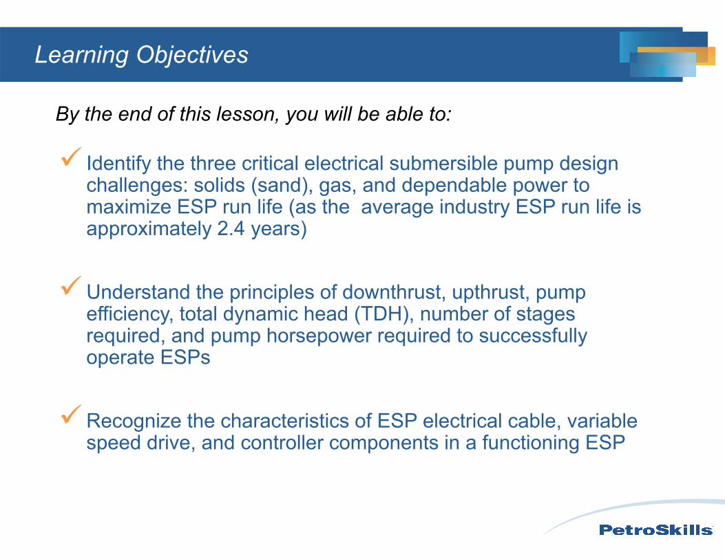
By the end of this lesson, you will be able to:
Identify the three critical electrical submersible pump design challenges: solids (sand), gas, and dependable power to maximize ESP run life (as the average industry ESP run life is approximately 2.4 years)
Understand the principles of downthrust, upthrust, pump efficiency, total dynamic head (TDH), number of stages required, and pump horsepower required to successfully operate ESPs
Recognize the characteristics of ESP electrical cable, variable speed drive, and controller components in a functioning ESP
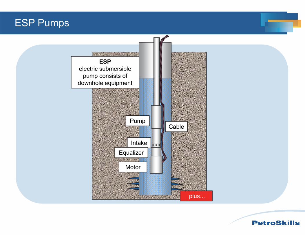
ESPelectric submersible
pump consists of downhole equipment
Pump
Intake
Motor
Cable
Equalizer
…plus...
ESP Pumps
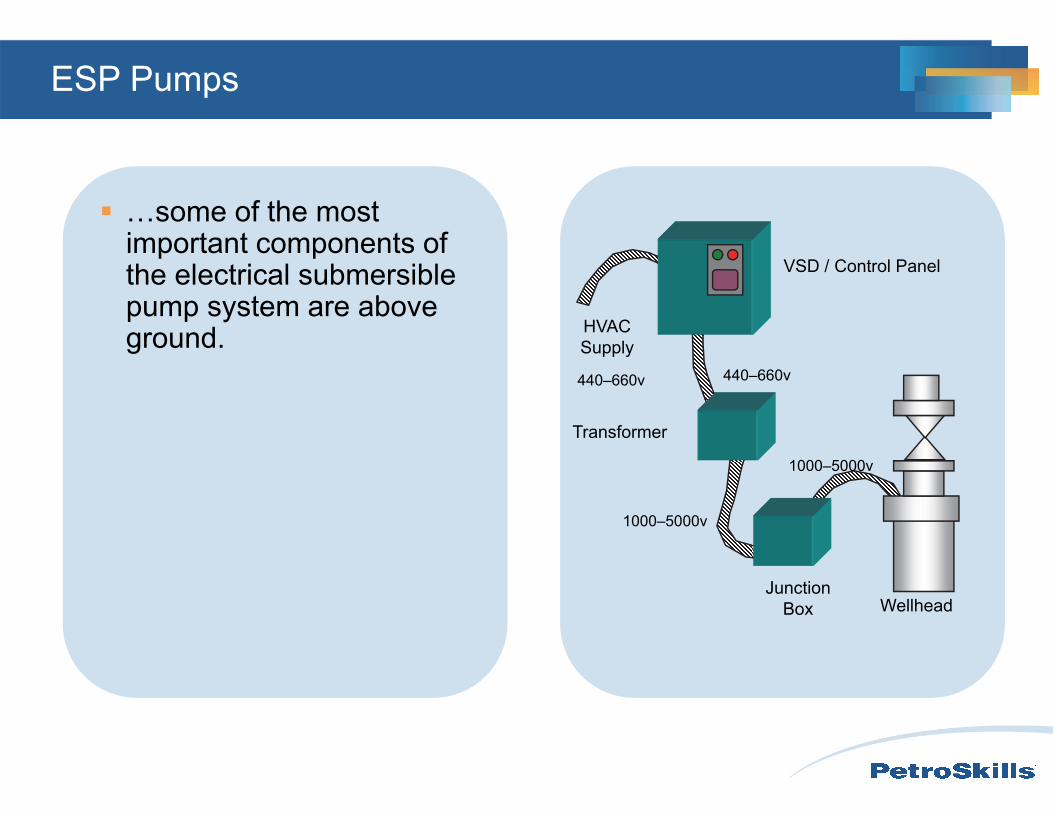
HVAC Supply
VSD / Control Panel
Junction Box Wellhead
Transformer
440–660v 440–660v
1000–5000v
1000–5000v
ESP Pumps
…some of the most important components of the electrical submersible pump system are above ground.
Electrical Submersible Pumps
The following ESP system component basics will be discussed by reviewing their function, their elements / parts, and their operation.
• Inflow and Outflow• The ESP System• Pump• Pump Intake• Motor• Equalizer• Cable• VSD• Operation
rimpelle
r
Electrical Submersible Pumps
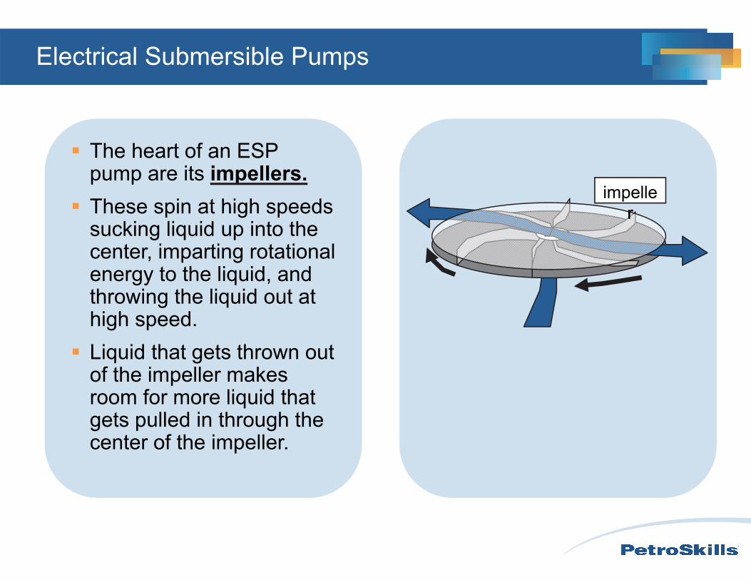
The heart of an ESP pump are its impellers.
These spin at high speeds sucking liquid up into the center, imparting rotational energy to the liquid, and throwing the liquid out at high speed.
Liquid that gets thrown out of the impeller makes room for more liquid that gets pulled in through the center of the impeller.
Diffuser
Electrical Submersible Pumps
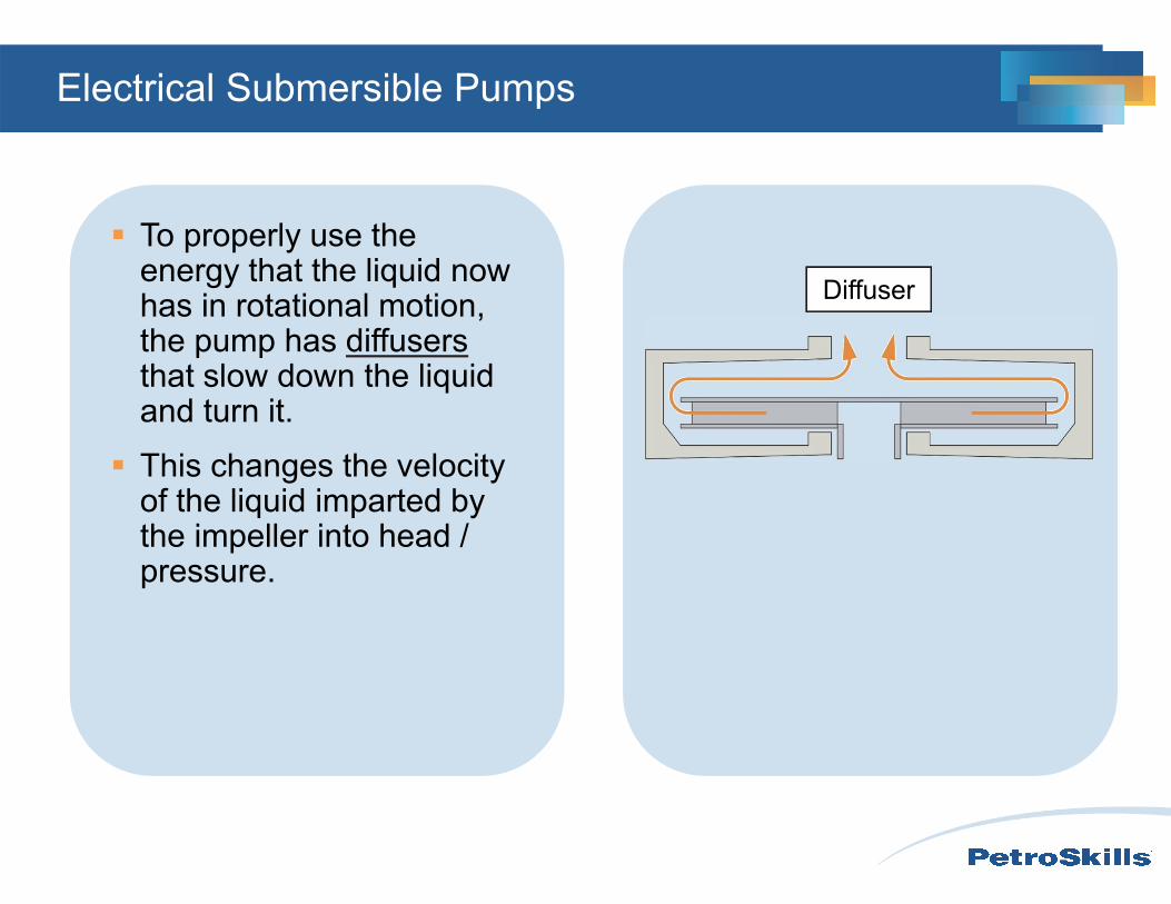
To properly use the energy that the liquid now has in rotational motion, the pump has diffusersthat slow down the liquid and turn it.
This changes the velocity of the liquid imparted by the impeller into head / pressure.
V
y u
impeller
Electrical Submersible Pumps
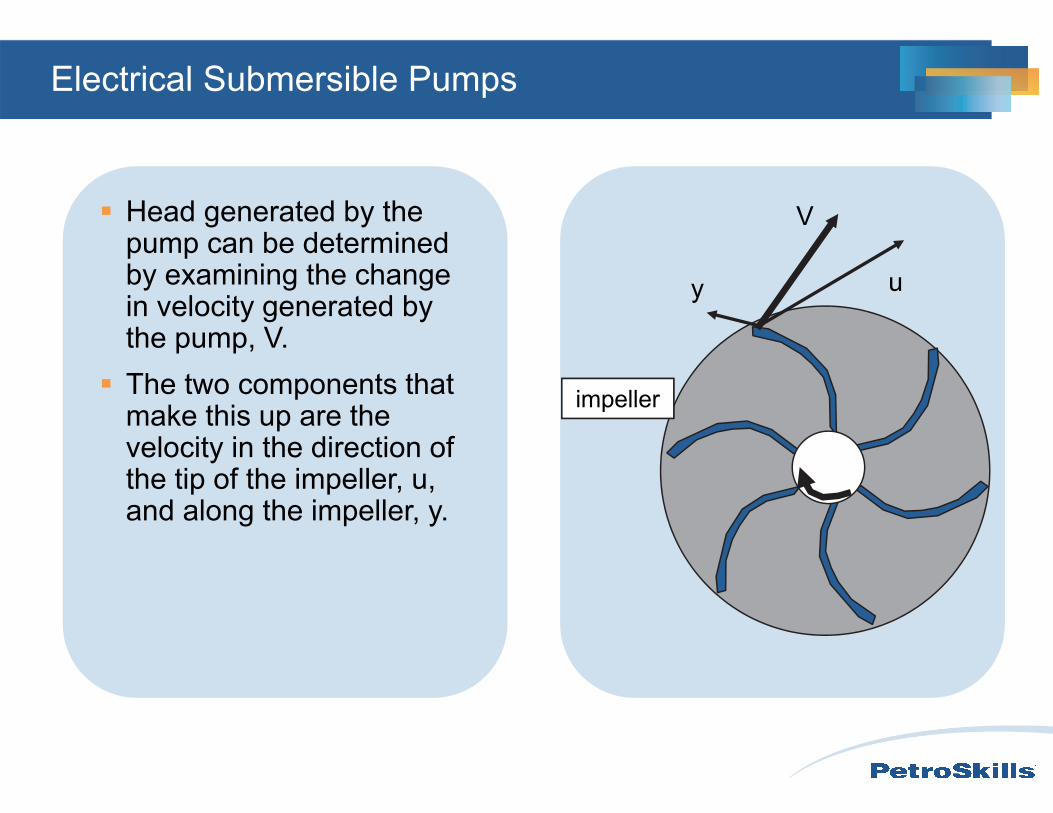
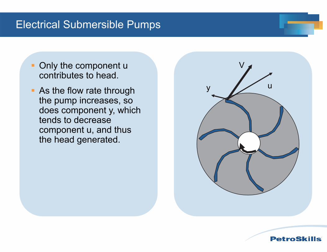
Head generated by the pump can be determined by examining the change in velocity generated by the pump, V.
The two components that make this up are the velocity in the direction of the tip of the impeller, u, and along the impeller, y.
V
y u
Electrical Submersible Pumps
Only the component u contributes to head.
As the flow rate through the pump increases, so does component y, which tends to decrease component u, and thus the head generated.
TDH
Rate
pump curve
Electrical Submersible Pumps
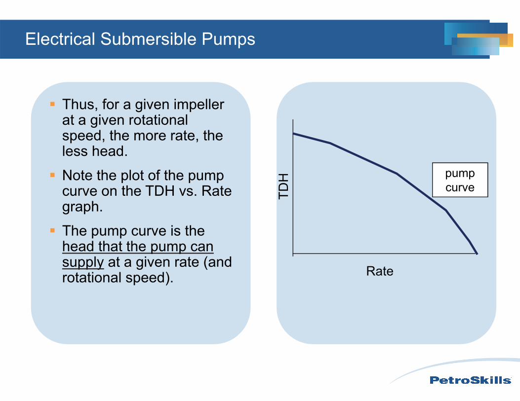
Thus, for a given impeller at a given rotational speed, the more rate, the less head.
Note the plot of the pump curve on the TDH vs. Rate graph.
The pump curve is the head that the pump can supply at a given rate (and rotational speed).
V
y u
Electrical Submersible Pumps
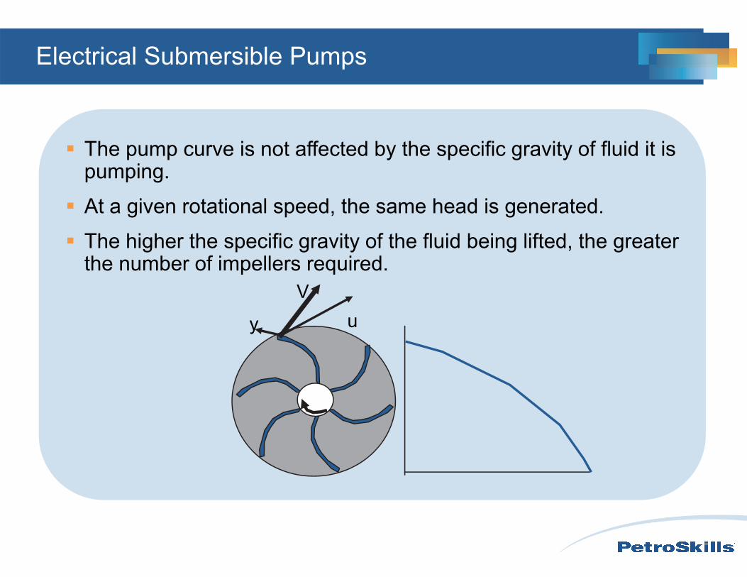
The pump curve is not affected by the specific gravity of fluid it is pumping.
At a given rotational speed, the same head is generated.
The higher the specific gravity of the fluid being lifted, the greater the number of impellers required.
Radial
Axial
Mixed
Electrical Submersible Pumps
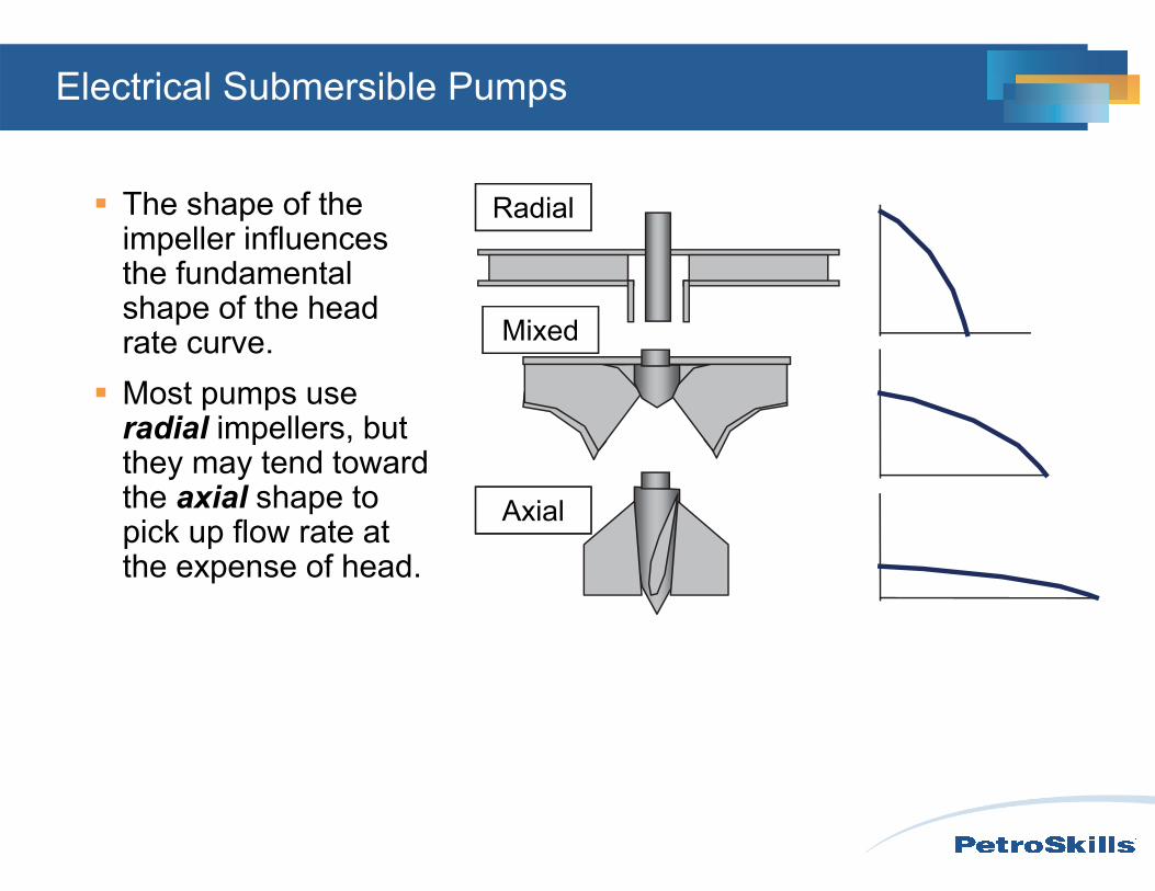
The shape of the impeller influences the fundamental shape of the head rate curve.
Most pumps use radial impellers, but they may tend toward the axial shape to pick up flow rate at the expense of head.
Electrical Submersible Pumps
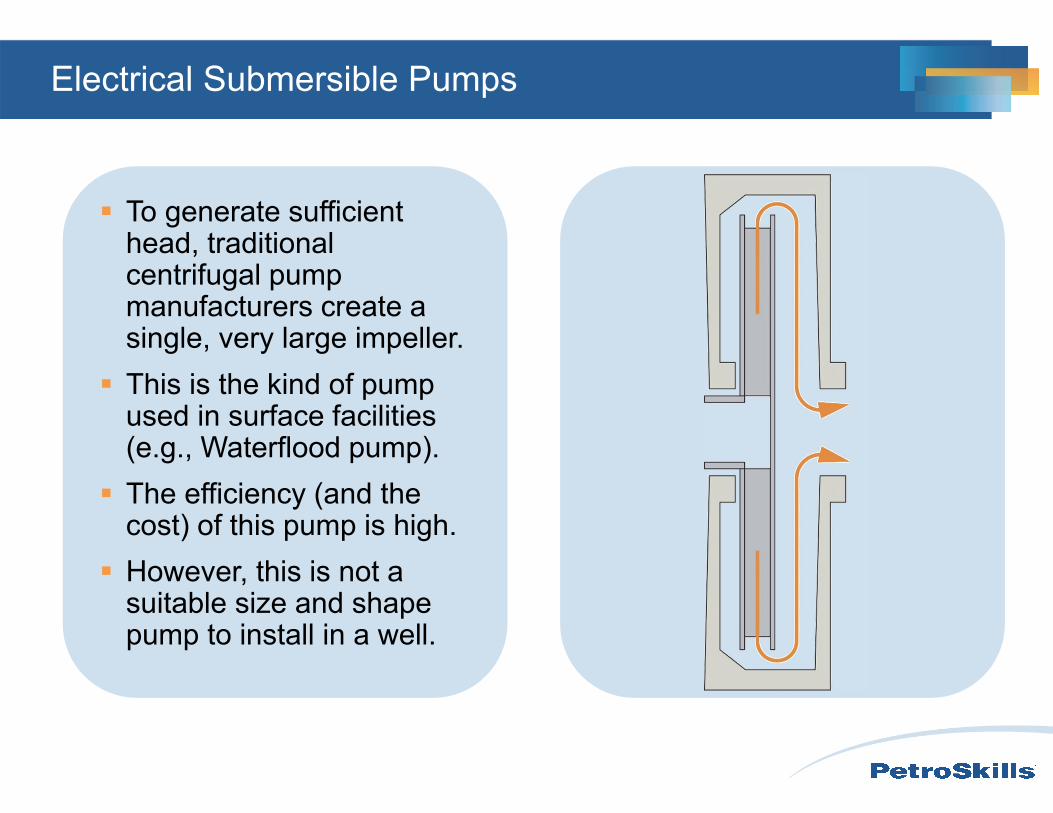
To generate sufficient head, traditional centrifugal pump manufacturers create a single, very large impeller.
This is the kind of pump used in surface facilities (e.g., Waterflood pump).
The efficiency (and the cost) of this pump is high.
However, this is not a suitable size and shape pump to install in a well.
Electrical Submersible Pumps
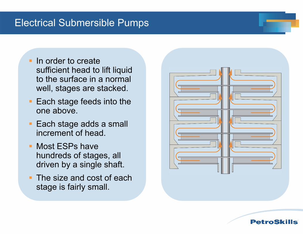
In order to create sufficient head to lift liquid to the surface in a normal well, stages are stacked.
Each stage feeds into the one above.
Each stage adds a small increment of head.
Most ESPs have hundreds of stages, all driven by a single shaft.
The size and cost of each stage is fairly small.
Electrical Submersible Pumps
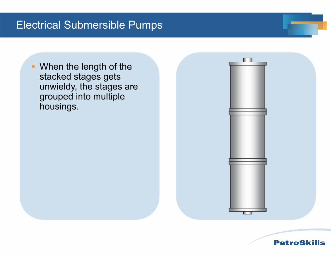
When the length of the stacked stages gets unwieldy, the stages are grouped into multiple housings.
Electrical Submersible Pumps
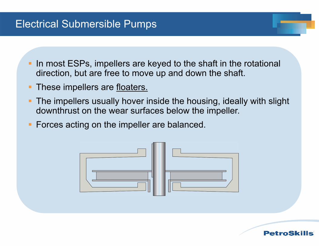
In most ESPs, impellers are keyed to the shaft in the rotational direction, but are free to move up and down the shaft.
These impellers are floaters. The impellers usually hover inside the housing, ideally with slight
downthrust on the wear surfaces below the impeller. Forces acting on the impeller are balanced.
Electrical Submersible Pumps
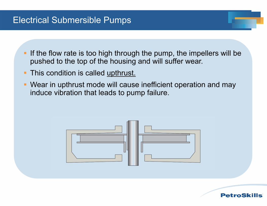
If the flow rate is too high through the pump, the impellers will be pushed to the top of the housing and will suffer wear.
This condition is called upthrust. Wear in upthrust mode will cause inefficient operation and may
induce vibration that leads to pump failure.
Electrical Submersible Pumps
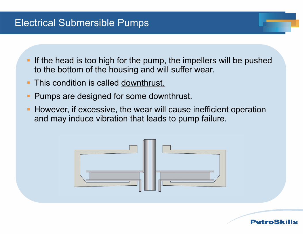
If the head is too high for the pump, the impellers will be pushed to the bottom of the housing and will suffer wear.
This condition is called downthrust. Pumps are designed for some downthrust. However, if excessive, the wear will cause inefficient operation
and may induce vibration that leads to pump failure.
Electrical Submersible Pumps
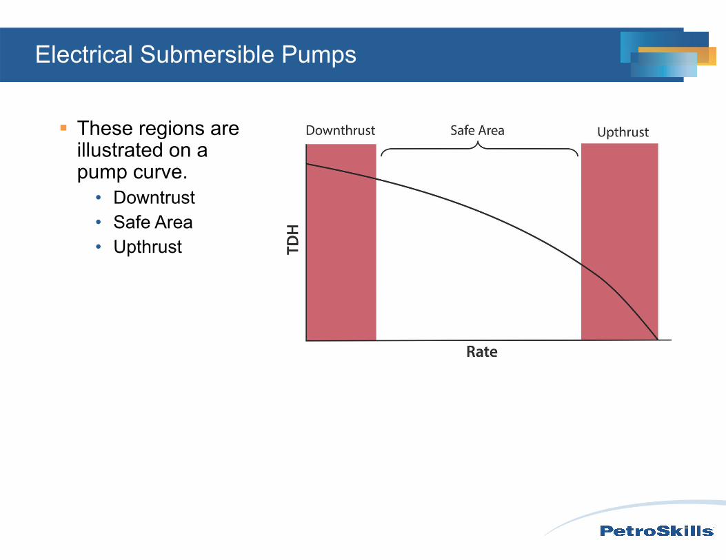
These regions are illustrated on a pump curve.
• Downtrust• Safe Area• Upthrust
Electrical Submersible Pumps
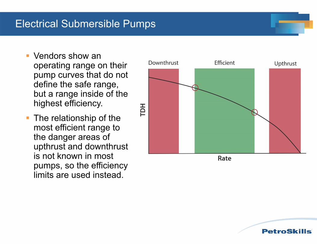
Vendors show an operating range on their pump curves that do not define the safe range, but a range inside of the highest efficiency.
The relationship of the most efficient range to the danger areas of upthrust and downthrustis not known in most pumps, so the efficiency limits are used instead.
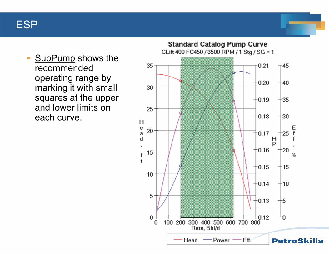
ESP
SubPump shows the recommended operating range by marking it with small squares at the upper and lower limits on each curve.
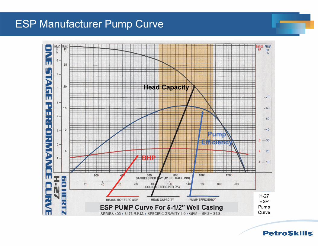
BHP
Head Capacity
Pump Efficiency
ESP Manufacturer Pump Curve
oil & water
oil & water & gas
bubble point
0
50 0
1000
1500
2000
2500
Rate
FBH
P
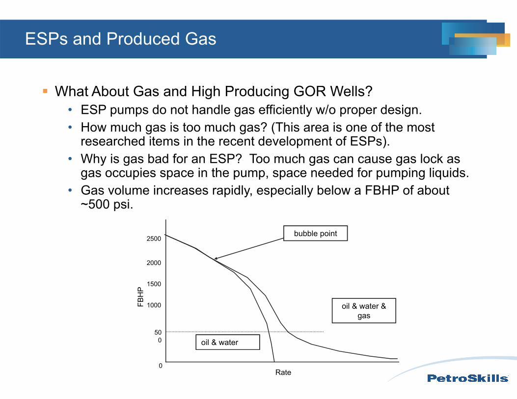
ESPs and Produced Gas
What About Gas and High Producing GOR Wells?• ESP pumps do not handle gas efficiently w/o proper design.• How much gas is too much gas? (This area is one of the most
researched items in the recent development of ESPs).• Why is gas bad for an ESP? Too much gas can cause gas lock as
gas occupies space in the pump, space needed for pumping liquids.• Gas volume increases rapidly, especially below a FBHP of about
~500 psi.
Pressure
Dep
th
annulus pressure
tubing pressure
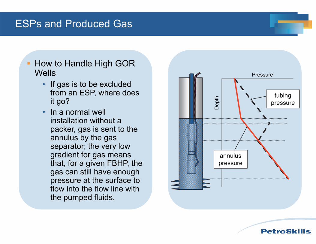
ESPs and Produced Gas
How to Handle High GOR Wells
• If gas is to be excluded from an ESP, where does it go?
• In a normal well installation without a packer, gas is sent to the annulus by the gas separator; the very low gradient for gas means that, for a given FBHP, the gas can still have enough pressure at the surface to flow into the flow line with the pumped fluids.
to equalizer
shaft to pumpgas and liquid to
pump
gas and liquid
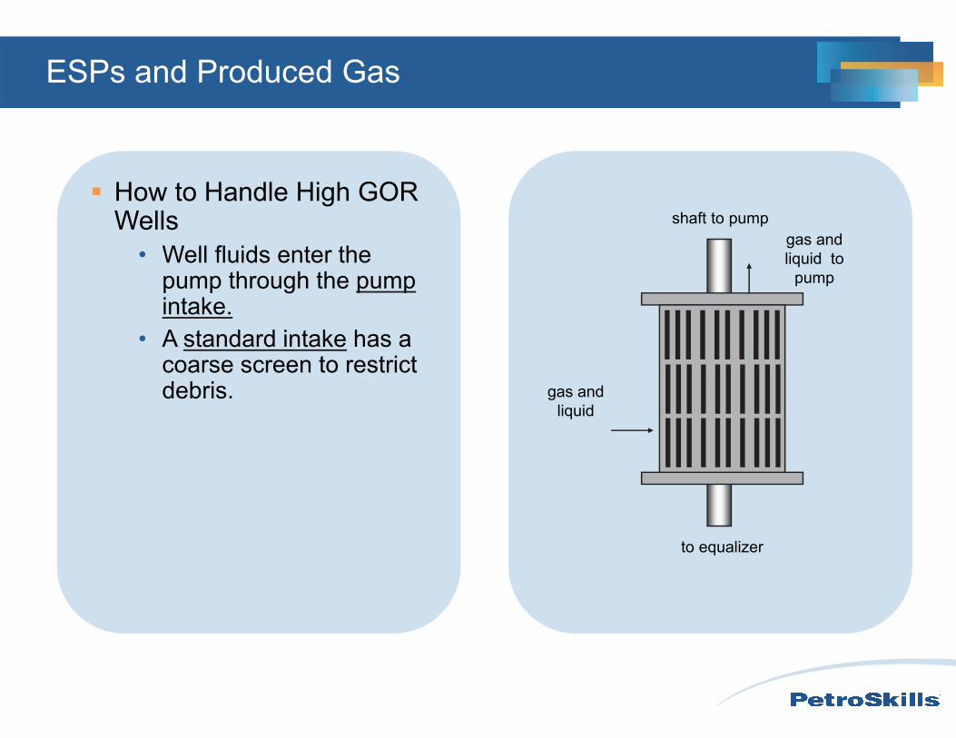
ESPs and Produced Gas
How to Handle High GOR Wells
• Well fluids enter the pump through the pump intake.
• A standard intake has a coarse screen to restrict debris.
to equalizer
shaftto pump liquid to
pumpgas to
annulus
separator impeller
standard intake
gas and liquid
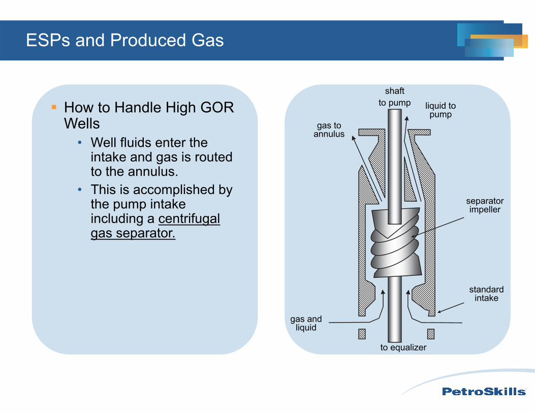
ESPs and Produced Gas
How to Handle High GOR Wells
• Well fluids enter the intake and gas is routed to the annulus.
• This is accomplished by the pump intake including a centrifugal gas separator.
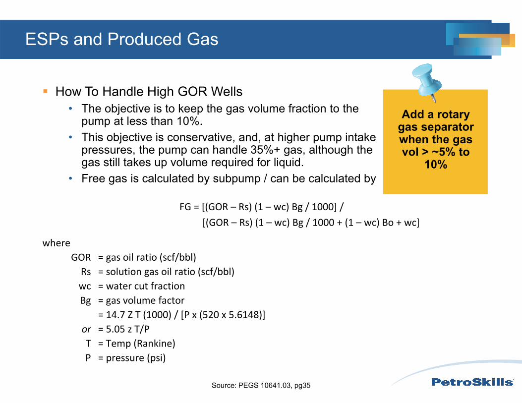
How To Handle High GOR Wells• The objective is to keep the gas volume fraction to the
pump at less than 10%.• This objective is conservative, and, at higher pump intake
pressures, the pump can handle 35%+ gas, although the gas still takes up volume required for liquid.
• Free gas is calculated by subpump / can be calculated by
Source: PEGS 10641.03, pg35
FG = [(GOR – Rs) (1 – wc) Bg / 1000] / [(GOR – Rs) (1 – wc) Bg / 1000 + (1 – wc) Bo + wc]
whereGOR = gas oil ratio (scf/bbl)Rs = solution gas oil ratio (scf/bbl)wc = water cut fractionBg = gas volume factor
= 14.7 Z T (1000) / [P x (520 x 5.6148)] or = 5.05 z T/PT = Temp (Rankine)P = pressure (psi)
ESPs and Produced Gas
Add a rotary gas separator when the gas vol > ~5% to
10%
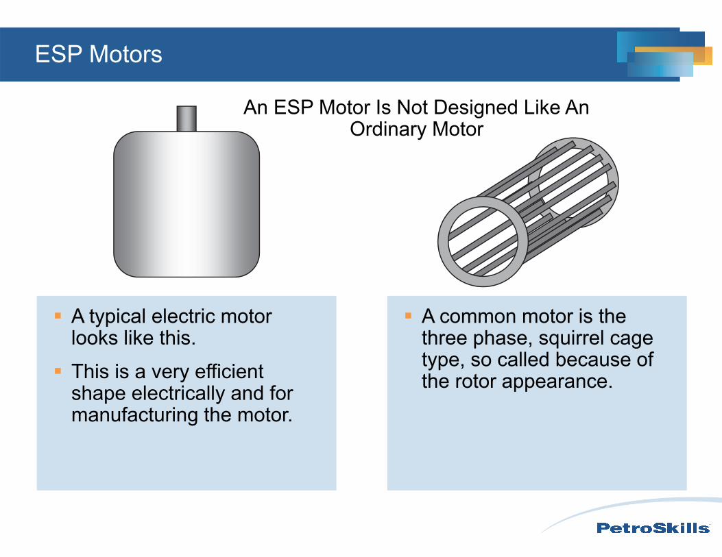
ESP Motors
A typical electric motor looks like this.
This is a very efficient shape electrically and for manufacturing the motor.
A common motor is the three phase, squirrel cage type, so called because of the rotor appearance.
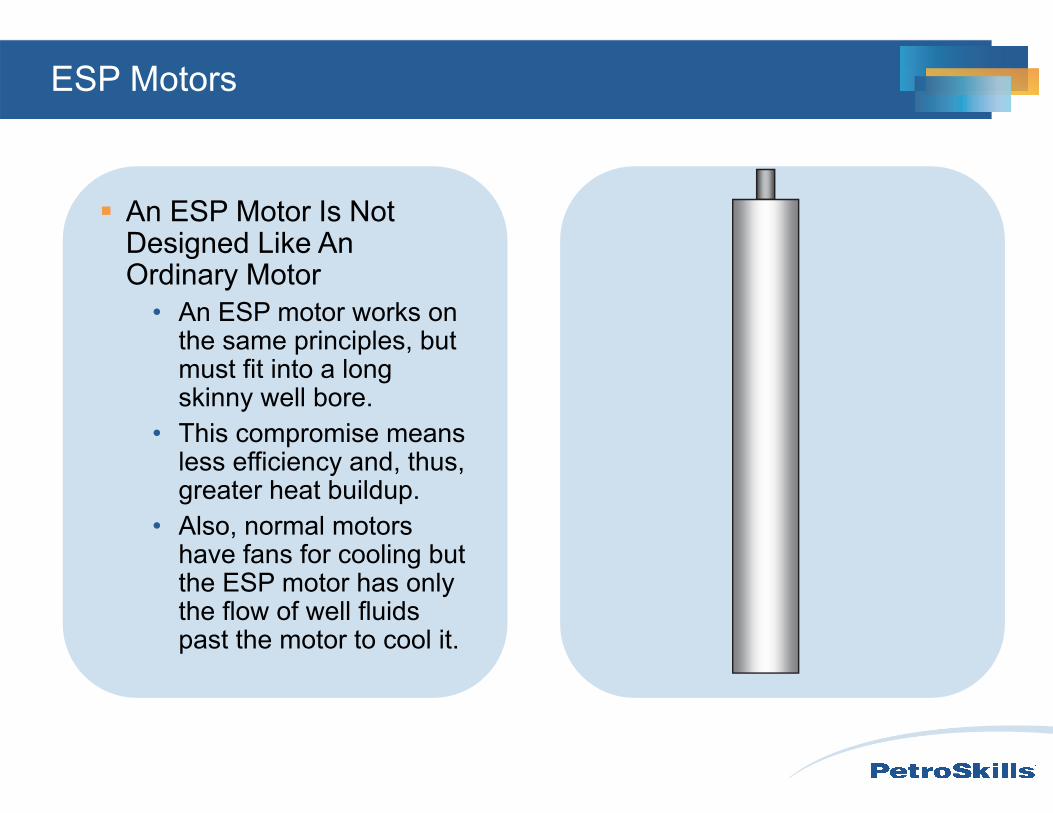
An ESP Motor Is Not Designed Like An Ordinary Motor
ESP Motors
An ESP Motor Is Not Designed Like An Ordinary Motor
• An ESP motor works on the same principles, but must fit into a long skinny well bore.
• This compromise means less efficiency and, thus, greater heat buildup.
• Also, normal motors have fans for cooling but the ESP motor has only the flow of well fluids past the motor to cool it.
ESP Equalizer
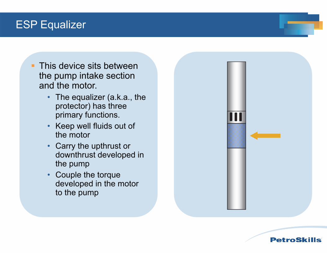
This device sits between the pump intake section and the motor.
• The equalizer (a.k.a., the protector) has three primary functions.
• Keep well fluids out of the motor
• Carry the upthrust or downthrust developed in the pump
• Couple the torque developed in the motor to the pump
ESP Equalizer
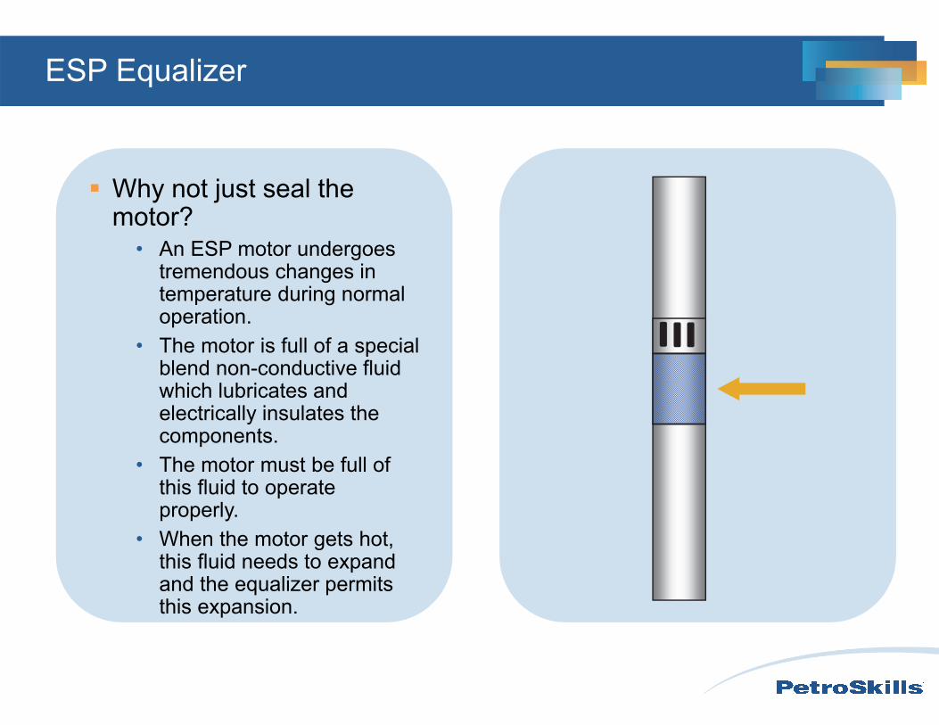
Why not just seal the motor?
• An ESP motor undergoes tremendous changes in temperature during normal operation.
• The motor is full of a special blend non-conductive fluid which lubricates and electrically insulates the components.
• The motor must be full of this fluid to operate properly.
• When the motor gets hot, this fluid needs to expand and the equalizer permits this expansion.
ESP Equalizer
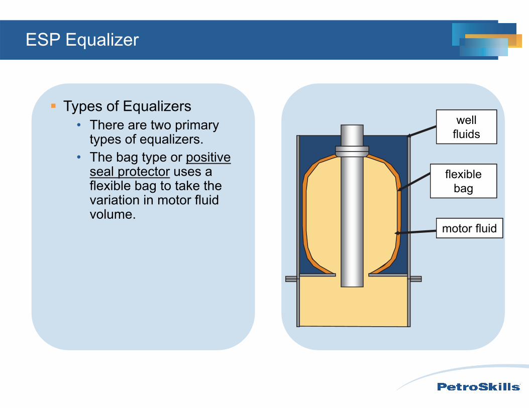
Types of Equalizers• There are two primary
types of equalizers.• The bag type or positive
seal protector uses a flexible bag to take the variation in motor fluid volume.
well fluids
motor fluid
flexible bag
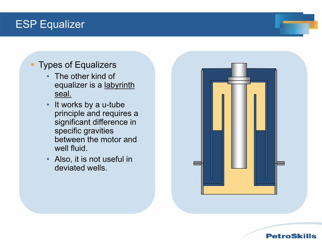
ESP Equalizer
Types of Equalizers• The other kind of
equalizer is a labyrinth seal.
• It works by a u-tube principle and requires a significant difference in specific gravities between the motor and well fluid.
• Also, it is not useful in deviated wells.
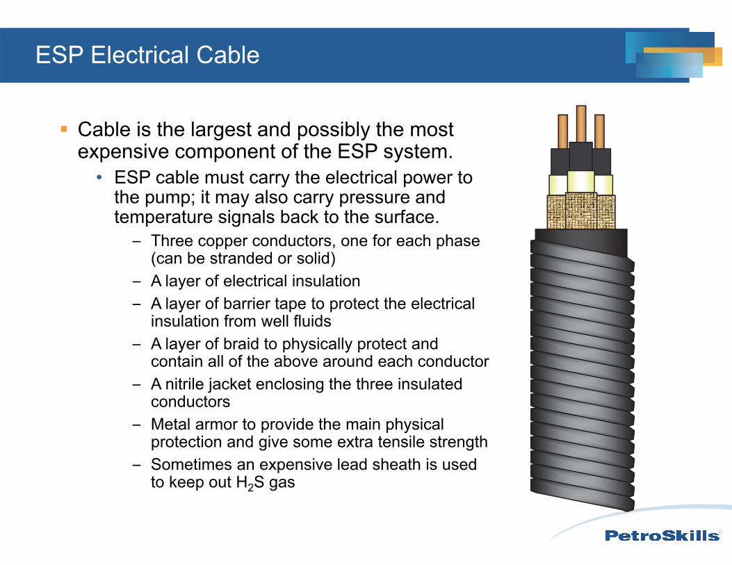
ESP Electrical Cable
Cable is the largest and possibly the most expensive component of the ESP system.
• ESP cable must carry the electrical power to the pump; it may also carry pressure and temperature signals back to the surface.
– Three copper conductors, one for each phase (can be stranded or solid)
– A layer of electrical insulation– A layer of barrier tape to protect the electrical
insulation from well fluids– A layer of braid to physically protect and
contain all of the above around each conductor– A nitrile jacket enclosing the three insulated
conductors– Metal armor to provide the main physical
protection and give some extra tensile strength– Sometimes an expensive lead sheath is used
to keep out H2S gas
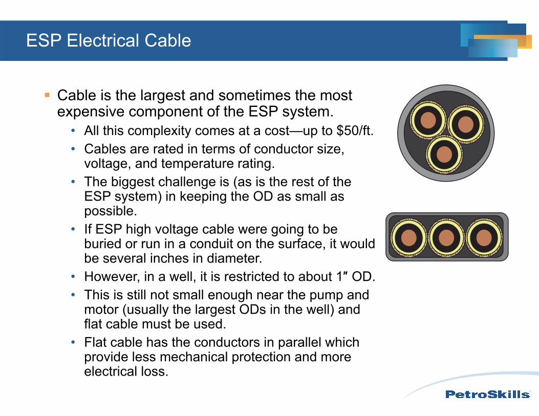
ESP Electrical Cable
Cable is the largest and sometimes the most expensive component of the ESP system.
• All this complexity comes at a cost—up to $50/ft.• Cables are rated in terms of conductor size,
voltage, and temperature rating.• The biggest challenge is (as is the rest of the
ESP system) in keeping the OD as small as possible.
• If ESP high voltage cable were going to be buried or run in a conduit on the surface, it would be several inches in diameter.
• However, in a well, it is restricted to about 1″ OD.• This is still not small enough near the pump and
motor (usually the largest ODs in the well) and flat cable must be used.
• Flat cable has the conductors in parallel which provide less mechanical protection and more electrical loss.
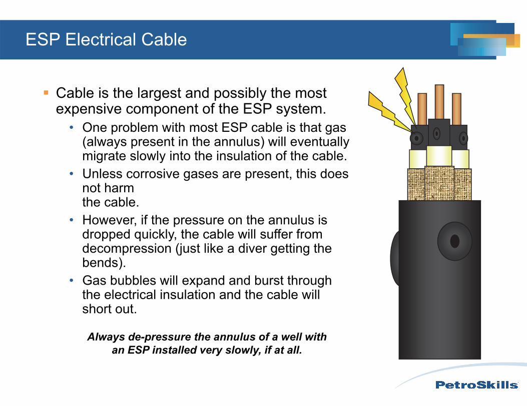
Always de-pressure the annulus of a well with an ESP installed very slowly, if at all.
ESP Electrical Cable
Cable is the largest and possibly the most expensive component of the ESP system.
• One problem with most ESP cable is that gas (always present in the annulus) will eventually migrate slowly into the insulation of the cable.
• Unless corrosive gases are present, this does not harm the cable.
• However, if the pressure on the annulus is dropped quickly, the cable will suffer from decompression (just like a diver getting the bends).
• Gas bubbles will expand and burst through the electrical insulation and the cable will short out.
ESP Variable Speed Drive VSD
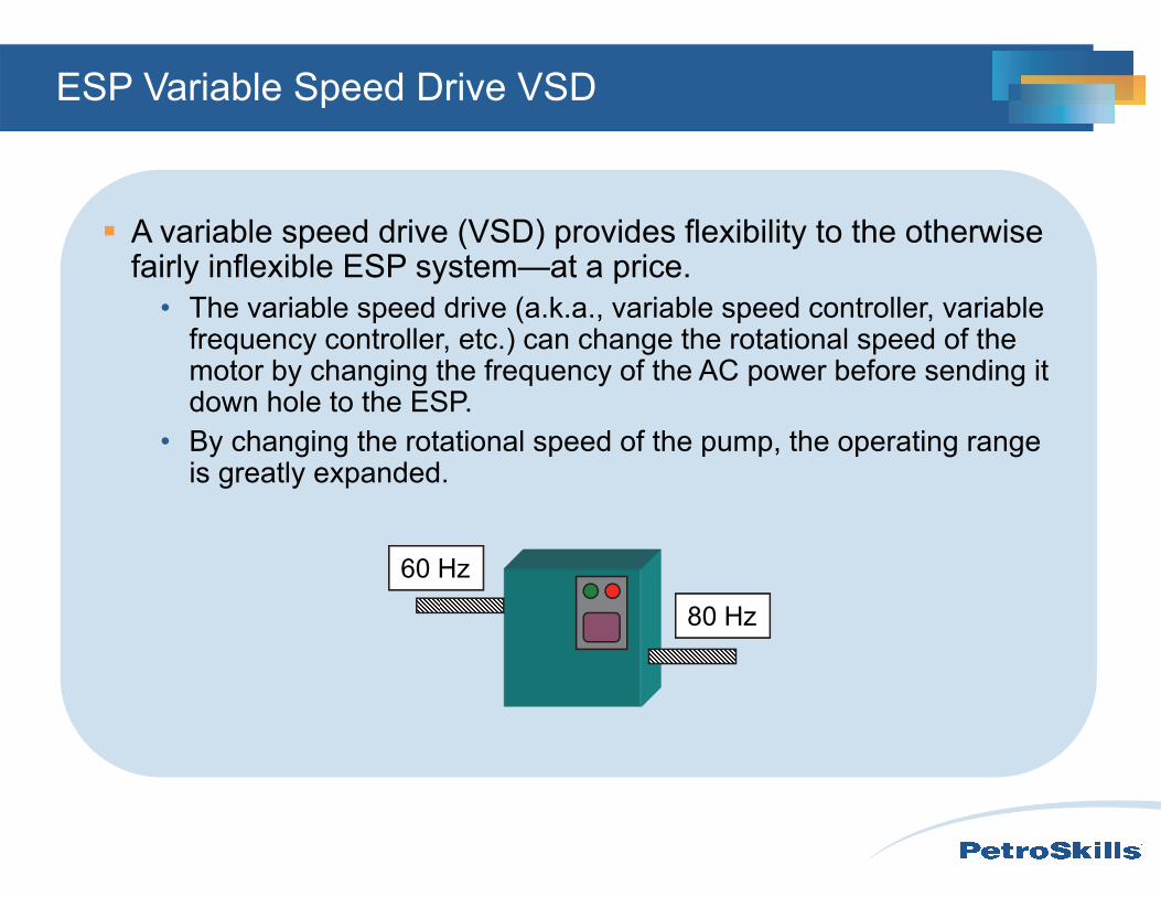
A variable speed drive (VSD) provides flexibility to the otherwise fairly inflexible ESP system—at a price.
• The variable speed drive (a.k.a., variable speed controller, variable frequency controller, etc.) can change the rotational speed of the motor by changing the frequency of the AC power before sending it down hole to the ESP.
• By changing the rotational speed of the pump, the operating range is greatly expanded.
60 Hz
80 Hz
ESP VSD
The VSD gives flexibility to the otherwise fairly inflexible ESP system—at a price.
• Reasons which justify installation of a VSD– Produce the well down to the limit of drawdown
(sand, gas, water influx)– Handle changing inflow performance (water flood response, pressure
depletion, deteriorating PI, etc.)– Keep power below power constraints– Test and produce at different rates– “Soft-start” that reduces start up current is included
ESP VSD
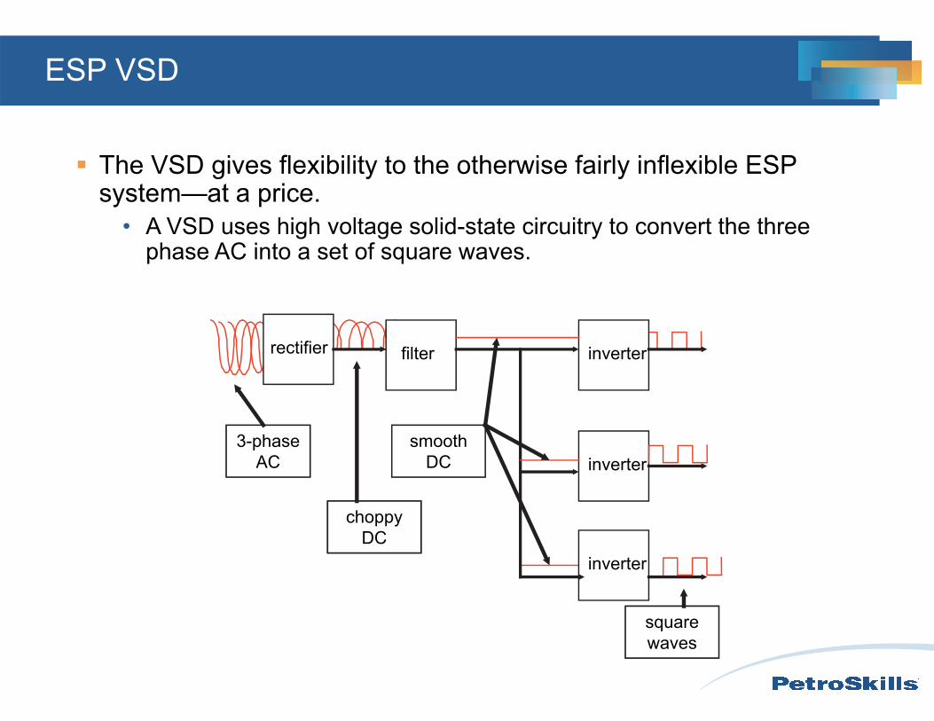
The VSD gives flexibility to the otherwise fairly inflexible ESP system—at a price.
• A VSD uses high voltage solid-state circuitry to convert the three phase AC into a set of square waves.
rectifier filter inverter
inverter
inverter
3-phase AC
choppy DC
smooth DC
square waves

ESP VSD
The VSD gives flexibility to the otherwise fairly inflexible ESP system—at a price.
• These square waves are combined to create a pseudo-sine wave for each phase.
ESP VSD
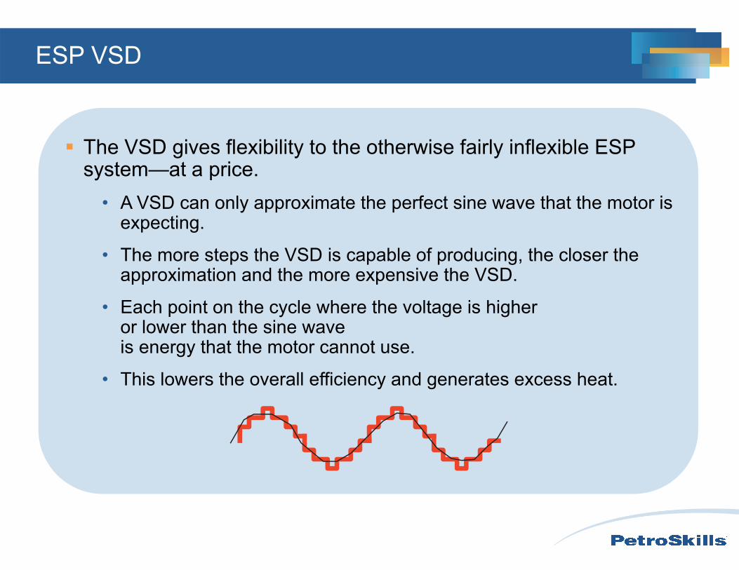
The VSD gives flexibility to the otherwise fairly inflexible ESP system—at a price.
• A VSD can only approximate the perfect sine wave that the motor is expecting.
• The more steps the VSD is capable of producing, the closer the approximation and the more expensive the VSD.
• Each point on the cycle where the voltage is higher or lower than the sine wave is energy that the motor cannot use.
• This lowers the overall efficiency and generates excess heat.
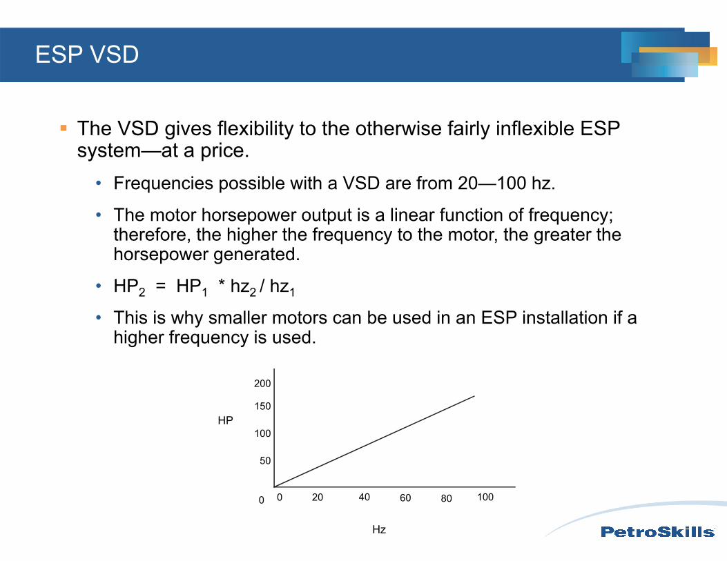
The VSD gives flexibility to the otherwise fairly inflexible ESP system—at a price.
• Frequencies possible with a VSD are from 20—100 hz.
• The motor horsepower output is a linear function of frequency; therefore, the higher the frequency to the motor, the greater the horsepower generated.
• HP2 = HP1 * hz2 / hz1
• This is why smaller motors can be used in an ESP installation if a higher frequency is used.
0
100
150
200
50
0 20 40 60 80 100
Hz
HP
ESP VSD
ESP VSD
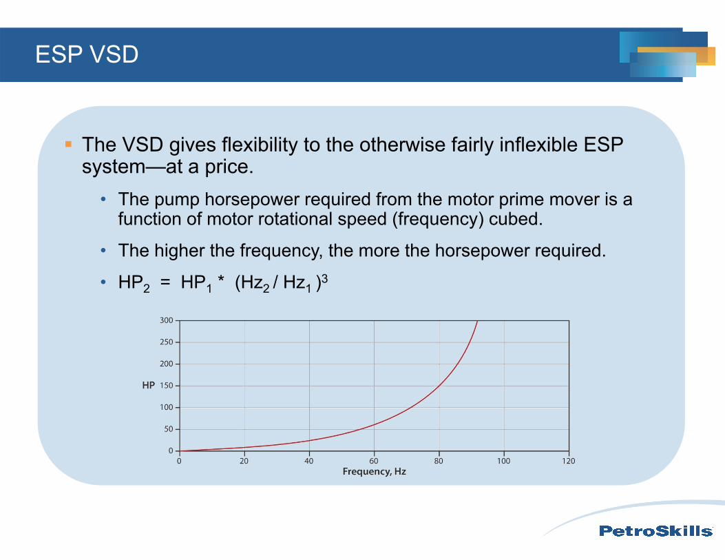
The VSD gives flexibility to the otherwise fairly inflexible ESP system—at a price.
• The pump horsepower required from the motor prime mover is a function of motor rotational speed (frequency) cubed.
• The higher the frequency, the more the horsepower required.
• HP2 = HP1 * (Hz2 / Hz1 )3
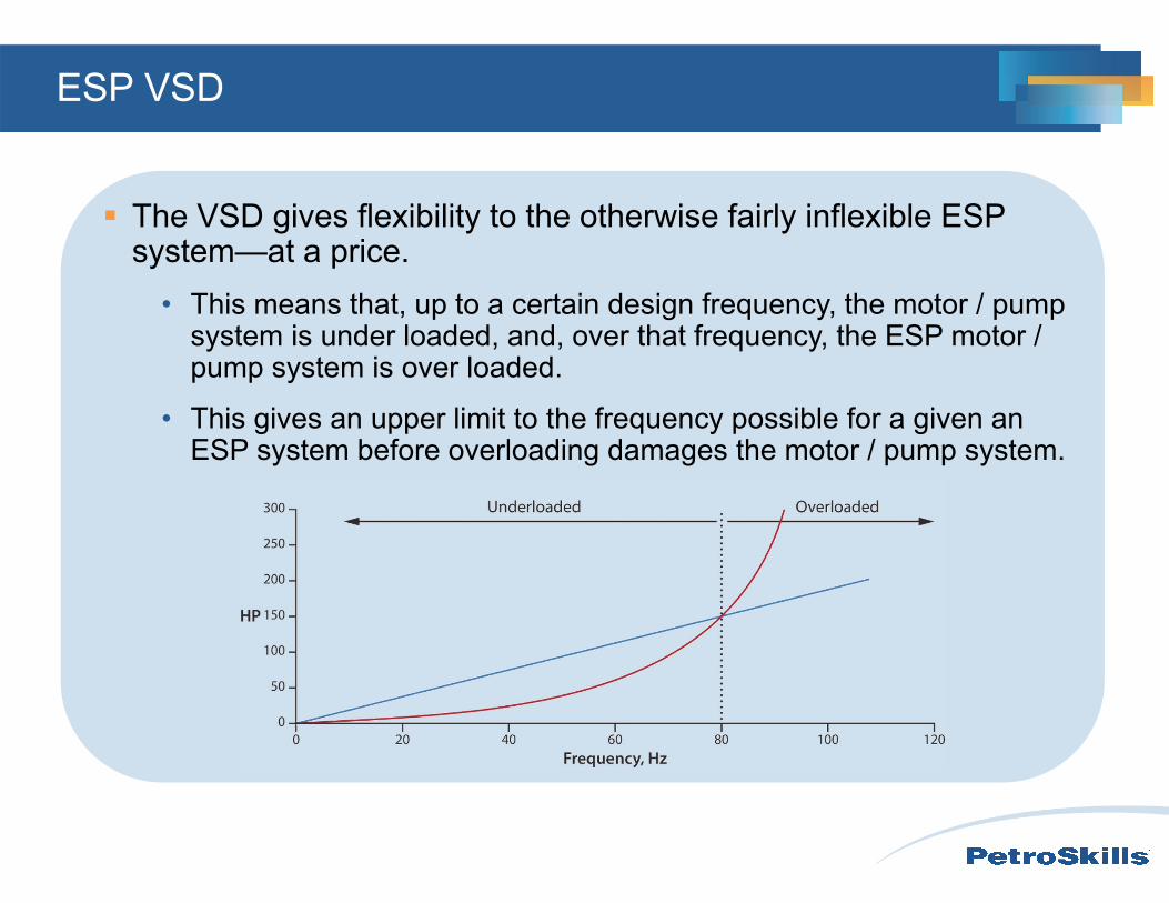
ESP VSD
The VSD gives flexibility to the otherwise fairly inflexible ESP system—at a price.
• This means that, up to a certain design frequency, the motor / pump system is under loaded, and, over that frequency, the ESP motor / pump system is over loaded.
• This gives an upper limit to the frequency possible for a given an ESP system before overloading damages the motor / pump system.
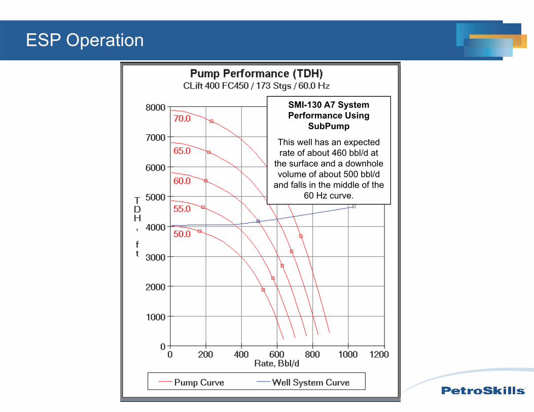
SMI-130 A7 System Performance Using
SubPump
This well has an expected rate of about 460 bbl/d at
the surface and a downhole volume of about 500 bbl/d
and falls in the middle of the 60 Hz curve.
ESP Operation
ESP
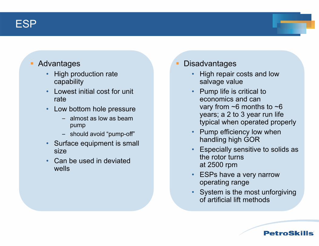
Advantages• High production rate
capability• Lowest initial cost for unit
rate• Low bottom hole pressure
– almost as low as beam pump
– should avoid “pump-off”• Surface equipment is small
size• Can be used in deviated
wells
Disadvantages• High repair costs and low
salvage value• Pump life is critical to
economics and can vary from ~6 months to ~6 years; a 2 to 3 year run life typical when operated properly
• Pump efficiency low when handling high GOR
• Especially sensitive to solids as the rotor turns at 2500 rpm
• ESPs have a very narrow operating range
• System is the most unforgiving of artificial lift methods
Learning Objectives
Identify the three critical electrical submersible pump design challenges: solids (sand), gas, and dependable power to maximize ESP run life (as the average industry ESP run life is approximately 2.4 years)
Understand the principles of downthrust, upthrust, pump efficiency, total dynamic head (TDH), number of stages required, and pump horsepower required to successfully operate ESPs
Recognize the characteristics of ESP electrical cable, variable speed drive, and controller components in a functioning ESP