Embed Size (px)
DESCRIPTION
As-Built Performance of the FPP Spectro-Polarimeter October, 2004 FPP Team. Bruce W. Lites 303 497 1517 [email protected]. FPP Spectro-Polarimeter Performance. AS-BUILT PERFORMANCE OF THE FPP-SP: Slit Scanning mechanism Vignetting as the image is scanned across the slit - PowerPoint PPT Presentation
Citation preview
1Lites
FPP-SP PerformanceSOT #17 Meeting, NAOJ,
April. 2006
Solar-BFPP
As-Built Performance of the FPP Spectro-Polarimeter
October, 2004
FPP Team
Bruce W. Lites
303 497 1517
2Lites
FPP-SP PerformanceSOT #17 Meeting, NAOJ,
April. 2006
Solar-BFPP FPP Spectro-Polarimeter Performance
AS-BUILT PERFORMANCE OF THE FPP-SP:• Slit Scanning mechanism
• Vignetting as the image is scanned across the slit
• Spectral response function
• Signal/Noise (polarimetric precision)
• Scattered Light
• System Polarization Calibration
3Lites
FPP-SP PerformanceSOT #17 Meeting, NAOJ,
April. 2006
Solar-BFPP Performance Requirements
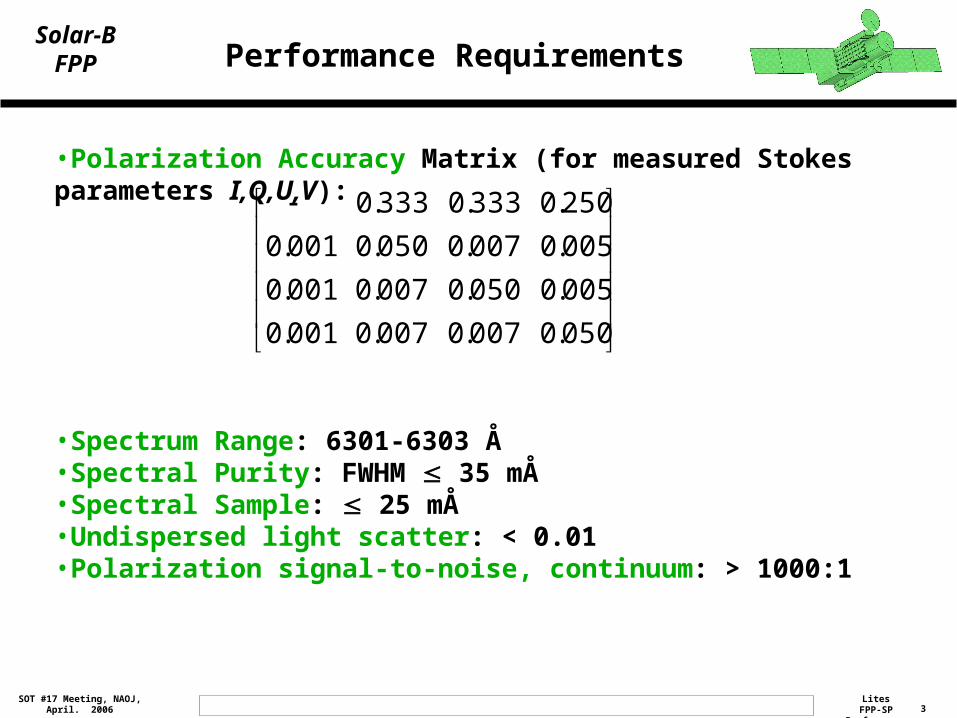
•Polarization Accuracy Matrix (for measured Stokes parameters I,Q,U,V):
•Spectrum Range: 6301-6303 Å•Spectral Purity: FWHM 35 mÅ•Spectral Sample: 25 mÅ•Undispersed light scatter: < 0.01•Polarization signal-to-noise, continuum: > 1000:1
050.0007.0007.0001.0
005.0050.0007.0001.0
005.0007.0050.0001.0
250.0333.0333.0
4Lites
FPP-SP PerformanceSOT #17 Meeting, NAOJ,
April. 2006
Solar-BFPP
Performance of the Slit Scanning Mechanism
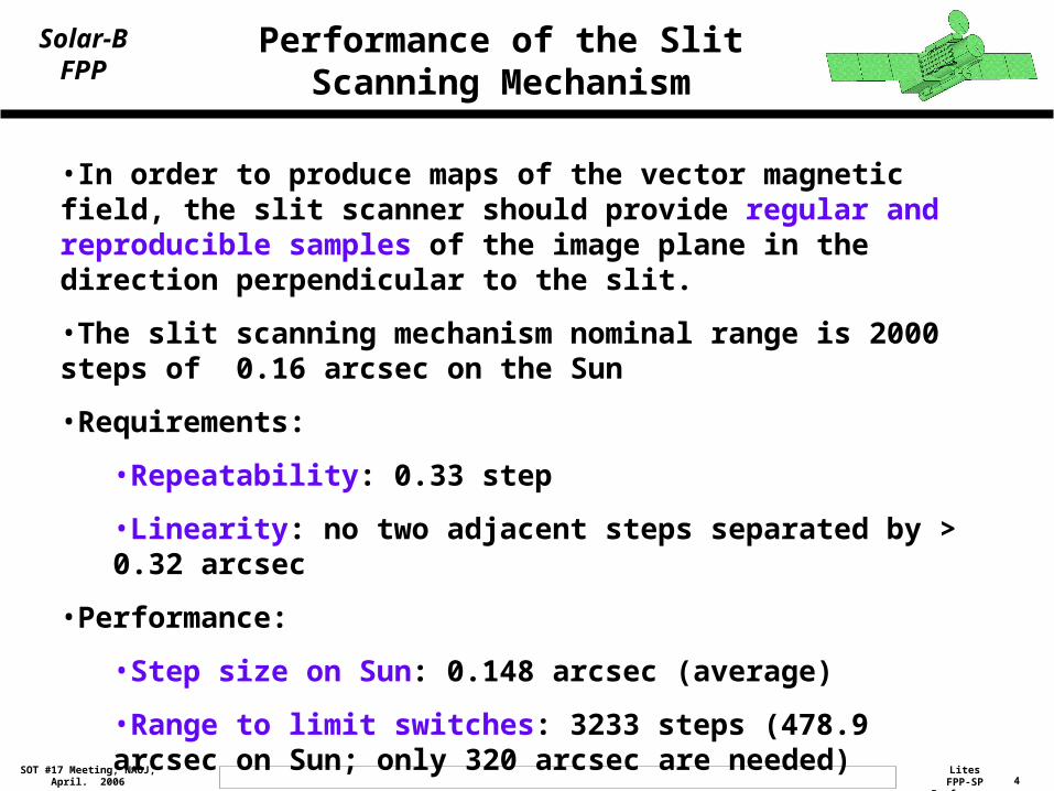
•In order to produce maps of the vector magnetic field, the slit scanner should provide regular and reproducible samples of the image plane in the direction perpendicular to the slit.
•The slit scanning mechanism nominal range is 2000 steps of 0.16 arcsec on the Sun
•Requirements:
•Repeatability: 0.33 step
•Linearity: no two adjacent steps separated by > 0.32 arcsec
•Performance:
•Step size on Sun: 0.148 arcsec (average)
•Range to limit switches: 3233 steps (478.9 arcsec on Sun; only 320 arcsec are needed)
5Lites
FPP-SP PerformanceSOT #17 Meeting, NAOJ,
April. 2006
Solar-BFPP
Theodolite Measurements of Slit Scanner
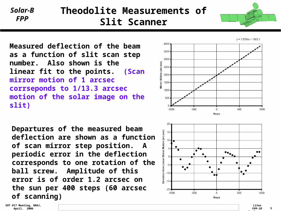
Measured deflection of the beam as a function of slit scan step number. Also shown is the linear fit to the points. (Scan mirror motion of 1 arcsec corrseponds to 1/13.3 arcsec motion of the solar image on the slit)
Departures of the measured beam deflection are shown as a function of scan mirror step position. A periodic error in the deflection corresponds to one rotation of the ball screw. Amplitude of this error is of order 1.2 arcsec on the sun per 400 steps (60 arcsec of scanning)
6Lites
FPP-SP PerformanceSOT #17 Meeting, NAOJ,
April. 2006
Solar-BFPP
Theodolite Measurements of Slit Scanner
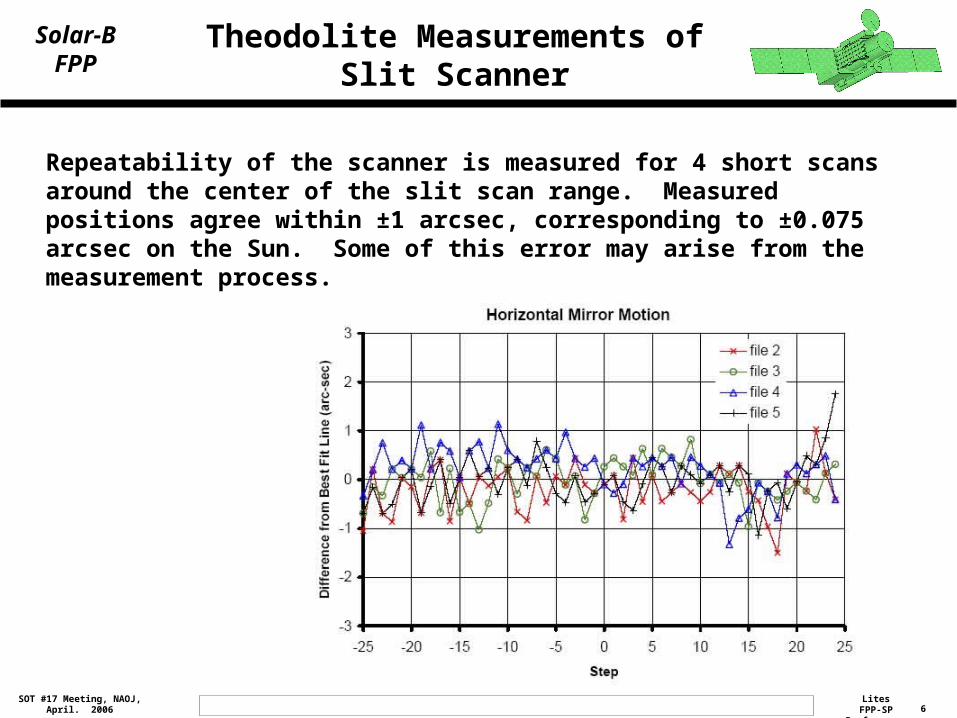
Repeatability of the scanner is measured for 4 short scans around the center of the slit scan range. Measured positions agree within ±1 arcsec, corresponding to ±0.075 arcsec on the Sun. Some of this error may arise from the measurement process.
7Lites
FPP-SP PerformanceSOT #17 Meeting, NAOJ,
April. 2006
Solar-BFPP
Optical Verification of Slit Scanner In Completed FPP
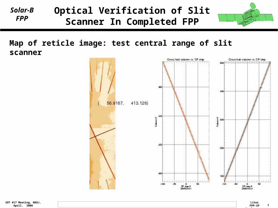
Map of reticle image: test central range of slit scanner
8Lites
FPP-SP PerformanceSOT #17 Meeting, NAOJ,
April. 2006
Solar-BFPP
Optical Verification of Slit Scanner In Completed FPP
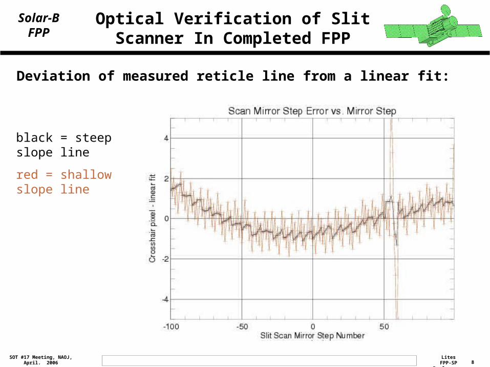
Deviation of measured reticle line from a linear fit:
black = steep slope line
red = shallow slope line
9Lites
FPP-SP PerformanceSOT #17 Meeting, NAOJ,
April. 2006
Solar-BFPP Slit Scanner Performance
•Large-scale sinusoidal variations in the slit scan step size: ~1.2 arcsec deviation from linear over 400 steps (60 arcsec)
•Short scans: positions are repeatable within about 0.15 arcsec peak (0.025 arcsec rms)
•No adjacent steps deviate by more than 1 step
10Lites
FPP-SP PerformanceSOT #17 Meeting, NAOJ,
April. 2006
Solar-BFPP
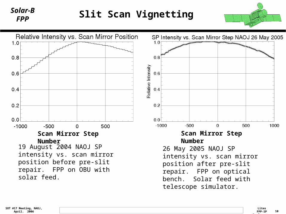
19 August 2004 NAOJ SP intensity vs. scan mirror position before pre-slit repair. FPP on OBU with solar feed.
Scan Mirror Step Number Scan Mirror Step Number
26 May 2005 NAOJ SP intensity vs. scan mirror position after pre-slit repair. FPP on optical bench. Solar feed with telescope simulator.
Slit Scan Vignetting
11Lites
FPP-SP PerformanceSOT #17 Meeting, NAOJ,
April. 2006
Solar-BFPP FPP-SP Spectral Resolution
Spectral resolution was monitored by measurement of the spectrum from the tunable laser
•Rotating diffuser in beam to reduce laser speckle
•Short integrations to minimize the effects of drift of the laser wavelength
Image at right shows sample laser measurement in both polarization images
Tuning the laser wavelength allows measurement of spectral response over the entire image plane
12Lites
FPP-SP PerformanceSOT #17 Meeting, NAOJ,
April. 2006
Solar-BFPP FPP-SP Spectral Resolution
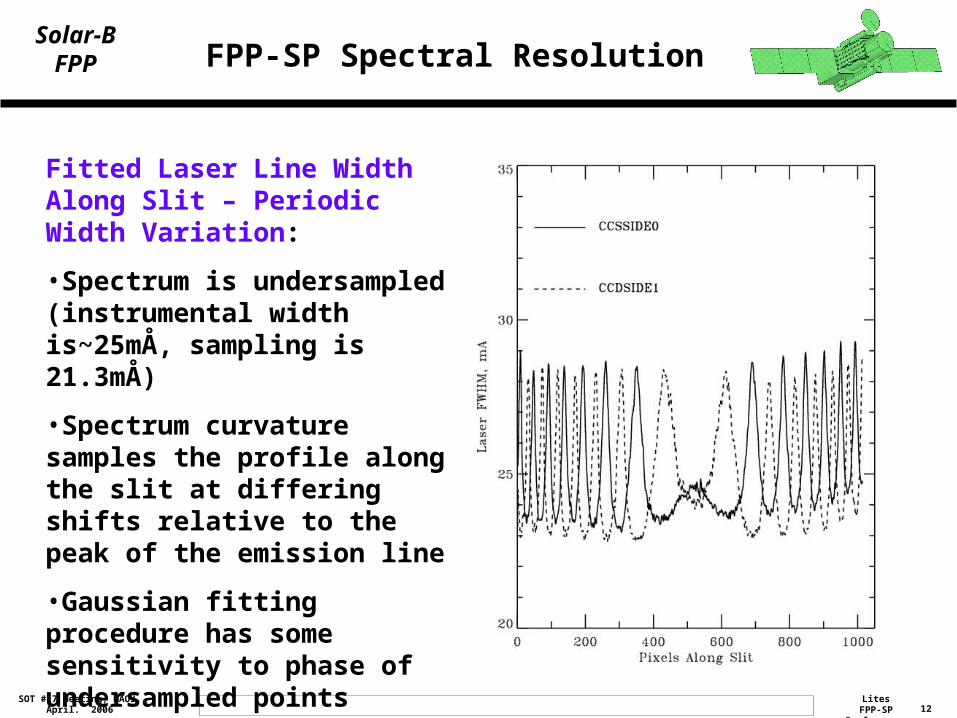
Fitted Laser Line Width Along Slit – Periodic Width Variation:
•Spectrum is undersampled (instrumental width is~25mÅ, sampling is 21.3mÅ)
•Spectrum curvature samples the profile along the slit at differing shifts relative to the peak of the emission line
•Gaussian fitting procedure has some sensitivity to phase of undersampled points relative to the emission line center
13Lites
FPP-SP PerformanceSOT #17 Meeting, NAOJ,
April. 2006
Solar-BFPP FPP-SP Spectral Resolution
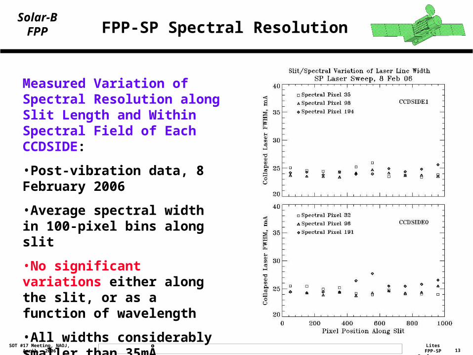
Measured Variation of Spectral Resolution along Slit Length and Within Spectral Field of Each CCDSIDE:
•Post-vibration data, 8 February 2006
•Average spectral width in 100-pixel bins along slit
•No significant variations either along the slit, or as a function of wavelength
•All widths considerably smaller than 35mÅ requirement
14Lites
FPP-SP PerformanceSOT #17 Meeting, NAOJ,
April. 2006
Solar-BFPP FPP-SP Spectral Resolution
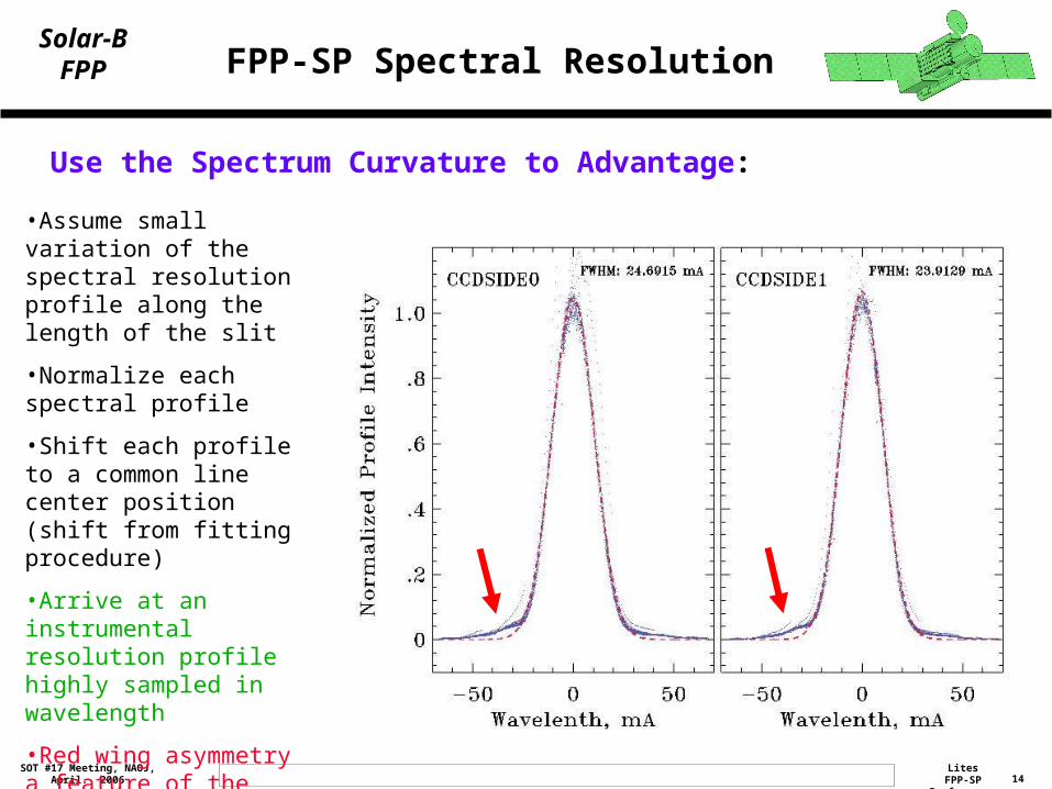
Use the Spectrum Curvature to Advantage:
•Assume small variation of the spectral resolution profile along the length of the slit
•Normalize each spectral profile
•Shift each profile to a common line center position (shift from fitting procedure)
•Arrive at an instrumental resolution profile highly sampled in wavelength
•Red wing asymmetry a feature of the spectrograph design
15Lites
FPP-SP PerformanceSOT #17 Meeting, NAOJ,
April. 2006
Solar-BFPP FPP-SP Polarization S/N
•FPP-SP flux levels measured
during Sun tests•Measurements of transmission
of heliostat and window•Solar radiance measurements
simultaneously during Sun
tests •Radiance measurements
calibrated to zero airmass
•These measurements and
extrapolations allow one to
extrapolate to the on-orbit S/N in
polarimetric measurements
Inputs:•Dark-corrected continuum intensity in raw measurement units (DN)•Measured SP CCD scale factor: 100 e-/DN•Read Noise: 110 e-•Heliostat transmission at 630 nm: 0.51•Atmospheric transmission at time of measurements: 0.58•Sum two sides of CCD•Polarization modulation efficiency: 0.5
Anticipated S/N, Typical 4.8 sec Integration:Continuum, Quiet Sun: 1100Line center, Quiet Sun: 580Line center, Umbra: 164
16Lites
FPP-SP PerformanceSOT #17 Meeting, NAOJ,
April. 2006
Solar-BFPP Scattered/Stray Light in the FPP-SP
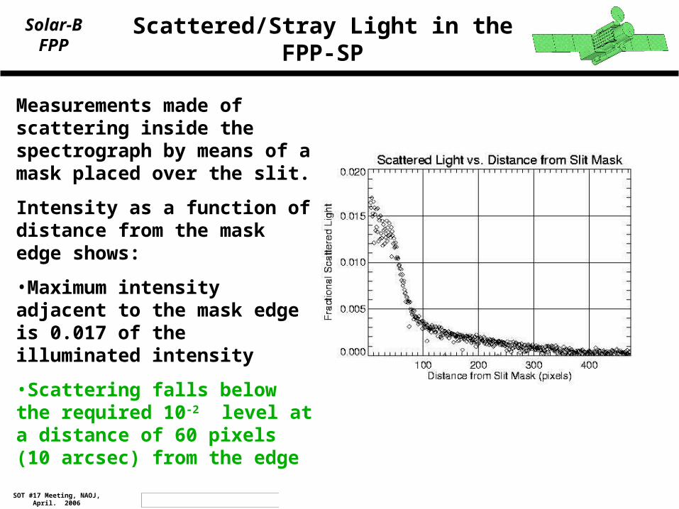
Measurements made of scattering inside the spectrograph by means of a mask placed over the slit.
Intensity as a function of distance from the mask edge shows:
•Maximum intensity adjacent to the mask edge is 0.017 of the illuminated intensity
•Scattering falls below the required 10-2 level at a distance of 60 pixels (10 arcsec) from the edge
17Lites
FPP-SP PerformanceSOT #17 Meeting, NAOJ,
April. 2006
Solar-BFPP FPP-SP Polarization Calibration
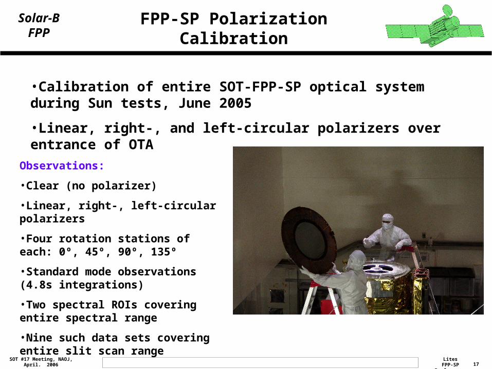
•Calibration of entire SOT-FPP-SP optical system during Sun tests, June 2005
•Linear, right-, and left-circular polarizers over entrance of OTA
Observations:
•Clear (no polarizer)
•Linear, right-, left-circular polarizers
•Four rotation stations of each: 0º, 45º, 90º, 135º
•Standard mode observations (4.8s integrations)
•Two spectral ROIs covering entire spectral range
•Nine such data sets covering entire slit scan range
18Lites
FPP-SP PerformanceSOT #17 Meeting, NAOJ,
April. 2006
Solar-BFPP FPP-SP Polarization Calibration
Data Analysis
•Bin data spatially along slit (16x) and spectrally (2x) to reduce data volume and increase S/N
•Normalize each Stokes vector observation to the measured Stokes I
•Each binned pixel for each CCDSIDE was subjected to a non-linear least-squares fitting procedure to determine:
•15 polarization response matrix elements ([0,0] element – I→I crosstalk – set to unity)
•Mount offset error of angular orientation for right- and for left-circular polarizers
19Lites
FPP-SP PerformanceSOT #17 Meeting, NAOJ,
April. 2006
Solar-BFPP FPP-SP Polarization Calibration
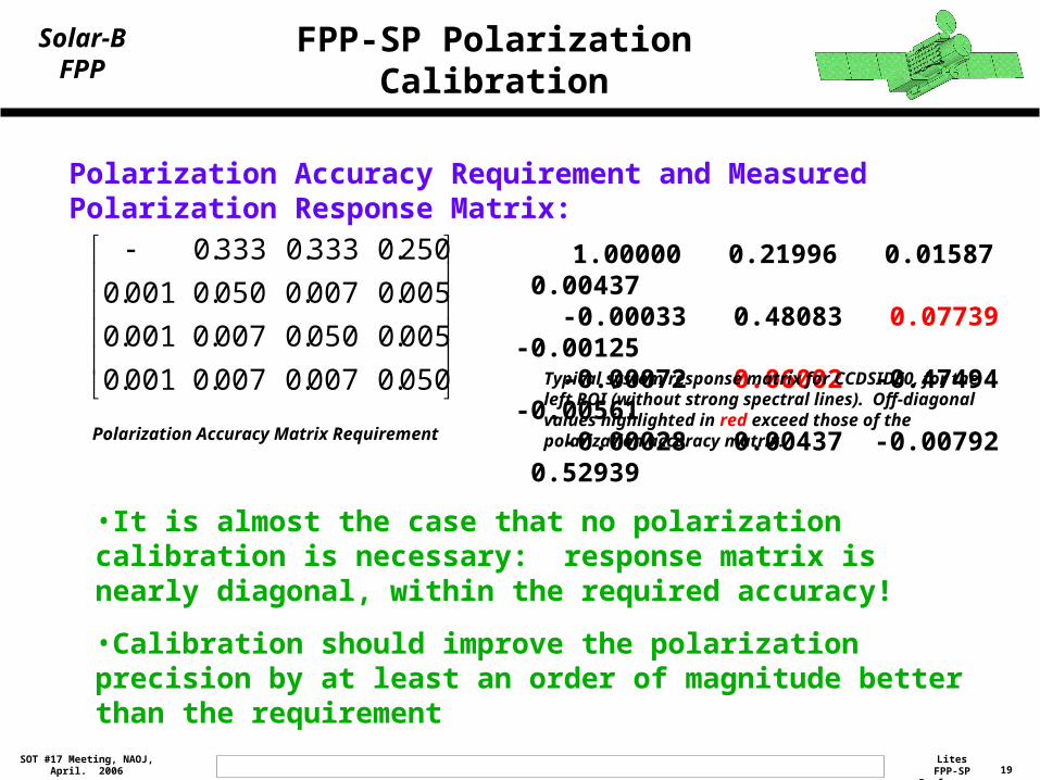
Polarization Accuracy Requirement and Measured Polarization Response Matrix:
1.00000 0.21996 0.01587 0.00437 -0.00033 0.48083 0.07739 -0.00125 -0.00072 0.06002 -0.47494 -0.00561 -0.00028 0.00437 -0.00792 0.52939
Typical system response matrix for CCDSIDE0, for the left ROI (without strong spectral lines). Off-diagonal values highlighted in red exceed those of the polarization accuracy matrix.
050.0007.0007.0001.0
005.0050.0007.0001.0
005.0007.0050.0001.0
250.0333.0333.0
Polarization Accuracy Matrix Requirement
•It is almost the case that no polarization calibration is necessary: response matrix is nearly diagonal, within the required accuracy!
•Calibration should improve the polarization precision by at least an order of magnitude better than the requirement
20Lites
FPP-SP PerformanceSOT #17 Meeting, NAOJ,
April. 2006
Solar-BFPP FPP-SP Polarization Calibration
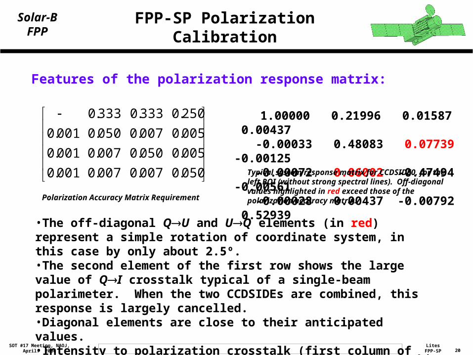
Features of the polarization response matrix:
1.00000 0.21996 0.01587 0.00437 -0.00033 0.48083 0.07739 -0.00125 -0.00072 0.06002 -0.47494 -0.00561 -0.00028 0.00437 -0.00792 0.52939
Typical system response matrix for CCDSIDE0, for the left ROI (without strong spectral lines). Off-diagonal values highlighted in red exceed those of the polarization accuracy matrix.
050.0007.0007.0001.0
005.0050.0007.0001.0
005.0007.0050.0001.0
250.0333.0333.0
Polarization Accuracy Matrix Requirement
•The off-diagonal QU and UQ elements (in red) represent a simple rotation of coordinate system, in this case by only about 2.5º.•The second element of the first row shows the large value of QI crosstalk typical of a single-beam polarimeter. When the two CCDSIDEs are combined, this response is largely cancelled.•Diagonal elements are close to their anticipated values.•Intensity to polarization crosstalk (first column of the matrix) is very small.
21Lites
FPP-SP PerformanceSOT #17 Meeting, NAOJ,
April. 2006
Solar-BFPP FPP-SP Polarization Calibration
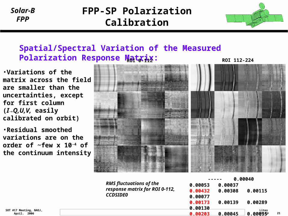
Spatial/Spectral Variation of the Measured Polarization Response Matrix: ROI 0-112 ROI 112-224
----- 0.00040 0.00053 0.000370.00432 0.00308 0.00115 0.000770.00173 0.00139 0.00289 0.001300.00203 0.00045 0.00035 0.00166
RMS fluctuations of the response matrix for ROI 0-112, CCDSIDE0
•Variations of the matrix across the field are smaller than the uncertainties, except for first column (I→Q,U,V, easily calibrated on orbit)
•Residual smoothed variations are on the order of ~few x 10-4 of the continuum intensity
22Lites
FPP-SP PerformanceSOT #17 Meeting, NAOJ,
April. 2006
Solar-BFPP FPP Spectro-Polarimeter Performance
SUMMARY:• The FPP-SP meets (and exceeds) its performance requirements
• Polarization calibration will be carried out as a function of wavelength, dimension along the slit, and slit scan position to account for small variations
• The spectral response function, highly sampled in wavelength, will be used in the inversion process
• Signal/Noise is higher than anticipated because of excess read noise in the cameras. Nonetheless, the goal of 1000:1 in the continuum per spectral/spatial pixel is achieved


![[O3] Polarimeter](https://img.pdfslide.net/doc/110x75/5571f2ce49795947648d1635/o3-polarimeter.jpg)
