Embed Size (px)
Citation preview

Ash and Material Handling Solutions

Table of Contents
Introduction Typical Fly Ash Conveying Systems Vacuum Fly Ash Conveying Pressure Fly Ash Conveying Vacuum/Pressure Fly Ash Conversion Hybrid Fly Ash Conveying Reprint – “Silo addition changes byproduct from waste to profit” Representative Projects
Scherer Coleto Creek Belews Creek Jack Watson Bowen Gadsden Sandow McDonough Crystal River North Texas Cement
Economizer Ash International
Introduction
L.B. Industrial Systems is a turnkey supplier of ash handling and other bulk material conveying, processing, and storage systems. With over twenty-five years of experience in projects for coal combustion by-products, cement, petroleum coke and other bulk powder materials, we deliver cost-effective services from feasibility studies through engineering, procurement, construction, start-up, performance certification, and operator training. Optimized Systems Design Every LB installation is designed and made to provide long, trouble-free operation for our customers under the most demanding operating conditions. We assess our customers’ unique needs and then apply the best available solution, utilizing both our proprietary equipment and specific 3rd party manufactured components which have proven reliable in our installations over the years. The results we deliver to our customers include better performance, less wear resulting in lower overall maintenance costs, and lower operating energy cost. LB optimized systems begin with the fundamentals of material handling science. Material properties, plant layout and Owner operating requirements allow us to determine basic system equipment sizing and piping routes. Our proprietary conveying software, including empirical data from our installed base of systems, allows us to size key components so that material flows freely within a controlled range of velocities. By controlling the conveying velocity in this manner, LB systems reduce wear at elbows and tees, while assuring material remains properly aerated and fluid. Typical LB systems require less horsepower for conveying, while providing for an appropriate reserve margin of conveying air supply.
Our Equipment and Systems Experience includes:
● Dilute Phase Vacuum and Pressure Conveying Systems
● Dense Phase Pressure Conveying Systems
● Mechanical Conveying Systems
● Concrete and Steel Silos ● Mass Storage Facilities ● Bins and Bunkers ● Dust Control Systems ● Truck and Rail Unloading
Systems ● Stand-alone and Networked
Control Systems ● Blending Systems ● Weighing Systems
● Ash Conditioning Systems ● Classification Systems ● Aeration Systems ● Compressed Air and Air
Drying Systems ● Grinding and Screening
Systems ● Carbon and Ammonia
Remediation Systems ● Drying Systems ● Sitework and Foundations ● Railways and Roadways ● Workshops, Control Rooms
and other plant buildings ● Electrical Power Distribution
and Control
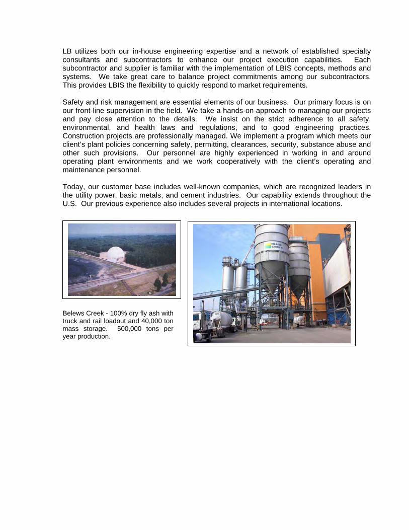
LB utilizes both our in-house engineering expertise and a network of established specialty consultants and subcontractors to enhance our project execution capabilities. Each subcontractor and supplier is familiar with the implementation of LBIS concepts, methods and systems. We take great care to balance project commitments among our subcontractors. This provides LBIS the flexibility to quickly respond to market requirements. Safety and risk management are essential elements of our business. Our primary focus is on our front-line supervision in the field. We take a hands-on approach to managing our projects and pay close attention to the details. We insist on the strict adherence to all safety, environmental, and health laws and regulations, and to good engineering practices. Construction projects are professionally managed. We implement a program which meets our client’s plant policies concerning safety, permitting, clearances, security, substance abuse and other such provisions. Our personnel are highly experienced in working in and around operating plant environments and we work cooperatively with the client’s operating and maintenance personnel. Today, our customer base includes well-known companies, which are recognized leaders in the utility power, basic metals, and cement industries. Our capability extends throughout the U.S. Our previous experience also includes several projects in international locations.
Belews Creek - 100% dry fly ash with truck and rail loadout and 40,000 ton mass storage. 500,000 tons per year production.
Vacuum Fly Ash Conveying System
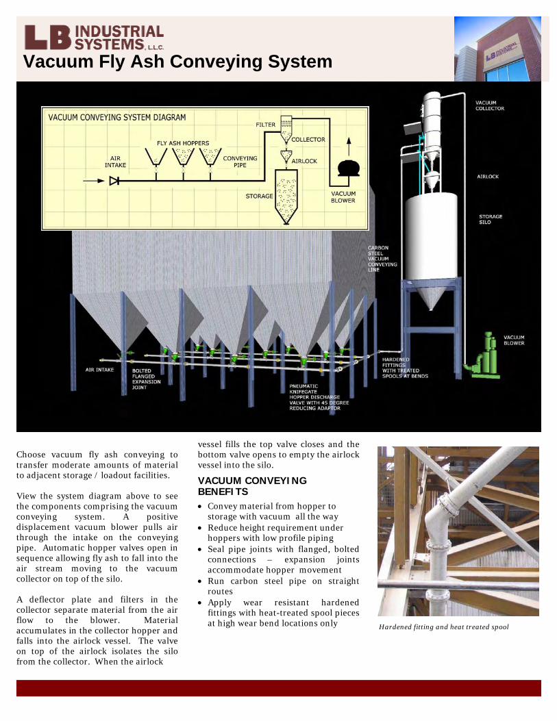
Choose vacuum fly ash conveying to transfer moderate amounts of material to adjacent storage / loadout facilities. View the system diagram above to see the components comprising the vacuum conveying system. A positive displacement vacuum blower pulls air through the intake on the conveying pipe. Automatic hopper valves open in sequence allowing fly ash to fall into the air stream moving to the vacuum collector on top of the silo. A deflector plate and filters in the collector separate material from the air flow to the blower. Material accumulates in the collector hopper and falls into the airlock vessel. The valve on top of the airlock isolates the silo from the collector. When the airlock
vessel fills the top valve closes and the bottom valve opens to empty the airlock vessel into the silo.
VACUUM CONVEYING BENEFITS • Convey material from hopper to
storage with vacuum all the way • Reduce height requirement under
hoppers with low profile piping • Seal pipe joints with flanged, bolted
connections – expansion joints accommodate hopper movement
• Run carbon steel pipe on straight routes
• Apply wear resistant hardened fittings with heat-treated spool pieces at high wear bend locations only
Hardened fitting and heat treated spool

Pressure Fly Ash Conveying System
Pressure fly ash conveying is the system often specified for new installations to transfer moderate to large amounts of material to storage / loadout facilities at remote locations of the plant. View the system diagram at right to see the components comprising the pressure conveying system. A rotary screw compressor produces transfer air to supply pressure feeder vessels and the conveying line. Automatic hopper valves open in sequence allowing fly ash to fall into a pressure feeder vessel under each hopper. The pressure conveying pipeline extends to the vertical riser pipe on the silo which delivers fly ash to the roof mounted inlet box. Transfer air is run through a coalescing filter. Each row of pressure vessels can be transferred into the branch line simultaneously permitting efficient transfer with fewer valves.
DENSE PHASE HIGH CAPACITY CONVEYING Top discharge feeders force material into the line ahead of the transport air making for a high solids-to-air ratio. Dense phase conveying means higher transfer rates and lower velocities. This helps reduce wear to fittings in the system.
PRESSURE CONVEYING BENEFITS • Convey material from hopper to
storage with pressure all the way • Unload one row of feeders at once –
unique system requires fewer valves • Reduce height requirement under
hoppers with low profile feeders • Suspend feeders from hoppers –
flexible discharge hose isolates movement
• Run carbon steel pipe on straight routes
• Apply wear resistant hardened fittings with heat-treated spool pieces at high wear bend locations only
• Hold conveying velocities to the optimum range for material suspension and low wear characteristics
Pressire feeder detail
Vacuum / Pressure Fly Ash Conveying System
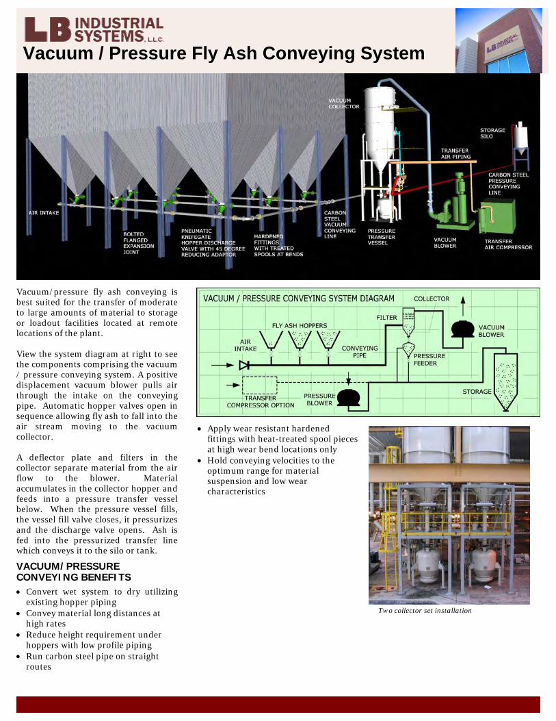
Vacuum/pressure fly ash conveying is best suited for the transfer of moderate to large amounts of material to storage or loadout facilities located at remote locations of the plant. View the system diagram at right to see the components comprising the vacuum / pressure conveying system. A positive displacement vacuum blower pulls air through the intake on the conveying pipe. Automatic hopper valves open in sequence allowing fly ash to fall into the air stream moving to the vacuum collector. A deflector plate and filters in the collector separate material from the air flow to the blower. Material accumulates in the collector hopper and feeds into a pressure transfer vessel below. When the pressure vessel fills, the vessel fill valve closes, it pressurizes and the discharge valve opens. Ash is fed into the pressurized transfer line which conveys it to the silo or tank.
VACUUM/PRESSURE CONVEYING BENEFITS • Convert wet system to dry utilizing
existing hopper piping • Convey material long distances at
high rates • Reduce height requirement under
hoppers with low profile piping • Run carbon steel pipe on straight
routes
• Apply wear resistant hardened fittings with heat-treated spool pieces at high wear bend locations only
• Hold conveying velocities to the optimum range for material suspension and low wear characteristics
Two collector set installation
Hybrid Fly Ash Conveying System
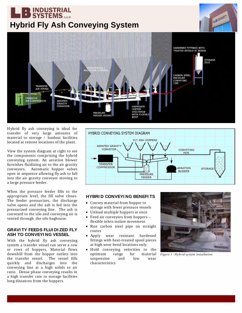
Hybrid fly ash conveying is ideal for transfer of very large amounts of material to storage / loadout facilities located at remote locations of the plant. View the system diagram at right to see the components comprising the hybrid conveying system. An aeration blower furnishes fluidizing air to the air gravity conveyors. Automatic hopper valves open in sequence allowing fly ash to fall into the air gravity conveyor moving to a large pressure feeder. When the pressure feeder fills to the appropriate level, the fill valve closes. The feeder pressurizes, the discharge valve opens and the ash is fed into the pressurized conveying line. The ash is conveyed to the silo and conveying air is vented through the silo baghouse.
GRAVITY FEEDS FLUIDIZED FLY ASH TO CONVEYING VESSEL With the hybrid fly ash conveying system a transfer vessel can serve a row or rows of hoppers. Material flows downhill from the hopper outlets into the transfer vessel. The vessel fills quickly and discharges into the conveying line at a high solids to air ratio. Dense phase conveying results in a high transfer rate to storage facilities long distances from the hoppers.
HYBRID CONVEYING BENEFITS • Convey material from hopper to
storage with fewer pressure vessels • Unload multiple hoppers at once • Feed air conveyors from hoppers –
flexible inlets isolate movement • Run carbon steel pipe on straight
routes • Apply wear resistant hardened
fittings with heat-treated spool pieces at high wear bend locations only
• Hold conveying velocities to the optimum range for material suspension and low wear characteristics
Figure 1 - Hybrid system installation
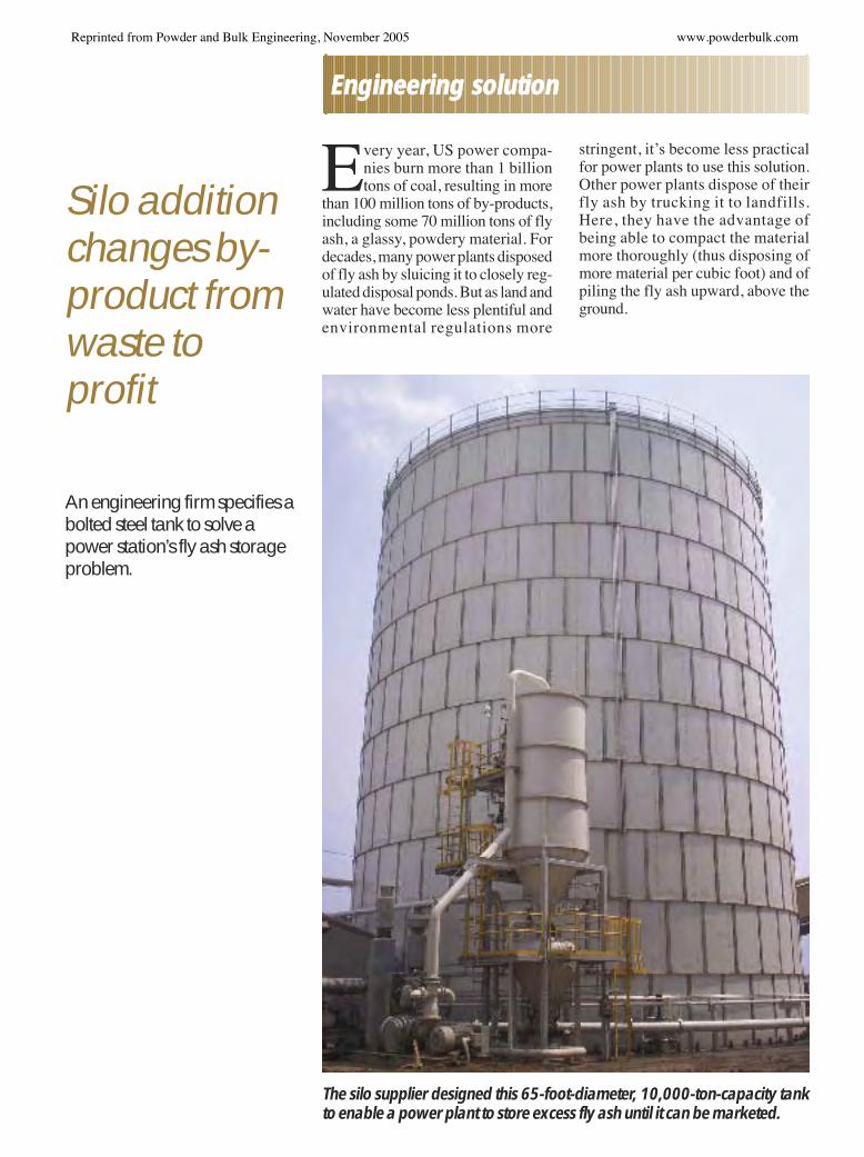
Silo additionchanges by-product fromwaste toprofit
An engineering firm specifies abolted steel tank to solve apower station’s fly ash storageproblem.
Every year, US power compa-nies burn more than 1 billiontons of coal, resulting in more
than 100 million tons of by-products,including some 70 million tons of flyash, a glassy, powdery material. Fordecades, many power plants disposedof fly ash by sluicing it to closely reg-ulated disposal ponds. But as land andwater have become less plentiful andenvironmental regulations more
stringent, it’s become less practicalfor power plants to use this solution.Other power plants dispose of theirfly ash by trucking it to landfills.Here, they have the advantage ofbeing able to compact the materialmore thoroughly (thus disposing ofmore material per cubic foot) and ofpiling the fly ash upward, above theground.
The silo supplier designed this 65-foot-diameter, 10,000-ton-capacity tankto enable a power plant to store excess fly ash until it can be marketed.
EEnnggiinneeeerriinngg ssoolluuttiioonn
Reprinted from Powder and Bulk Engineering, November 2005 www.powderbulk.com
However, many power plants nolonger want to dispose of their fly ashin either of these ways: Fly ash has be-come a valuable commodity. It’swidely used as an ingredient in con-crete, replacing a portion of the port-land cement used as concrete’s activeingredient.
During the past two decades or so, thenumber of power plants seeking tosell their fly ash rather than dispose ofit has significantly increased. This isespecially true of power plants thatuse western coal from the PowderRiver Basin in Wyoming. Nearly 50percent of the coal used by powerplants now comes from this area. Thecoal there is lower in sulfur than coalsfrom other areas, and it produces rela-tively less fly ash. The fly ash itself ishigher in calcium, which makes itmore desirable in the concrete indus-try than other fly ash.
Converting the fly ash handlingsystemThe problem for most power plantshas been converting their fly ash han-dling systems from sluicing to selling.That’s where L.B. Industrial SystemsLLC, a San Antonio-based turnkeyengineering and contracting firm,comes in. The firm specializes in thistype of conversion.
The firm is only a few years old; how-ever, the core personnel have been inthis business a long time. Bob Lister,the firm’s president, got his start with acompany that marketed fly ash frompower stations. He later became thatcompany’s engineering departmenthead. During the 25 or so years heworked there, the engineering depart-ment developed many of its own tech-nologies. In July 2001, the engineeringdepartment demerged from the com-
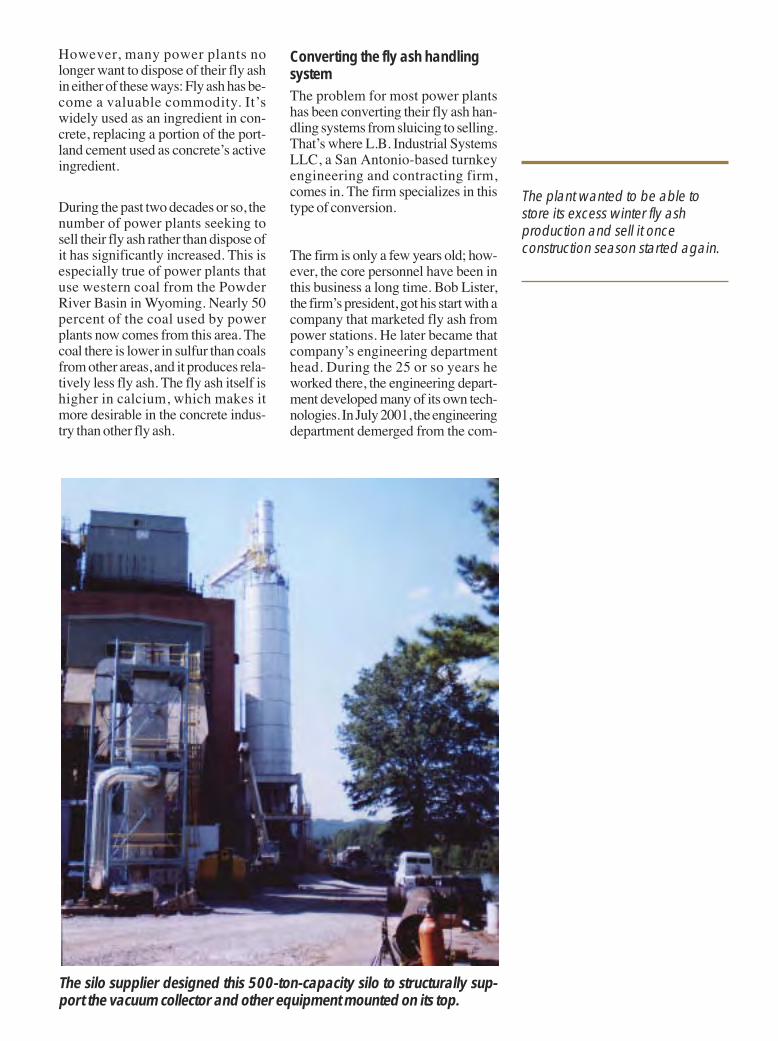
The plant wanted to be able tostore its excess winter fly ashproduction and sell it onceconstruction season started again.
The silo supplier designed this 500-ton-capacity silo to structurally sup-port the vacuum collector and other equipment mounted on its top.
pany and started its own firm, L.B. In-dustrial Systems. Today, the firm con-tinues to do contract work for thatcompany as well as many others.
Undertaking a conversion projectAbout 3 years ago, a major southeast-ern US power company came to L.B.Industrial and contracted their ser-vices to convert a large power plantfrom ponding its fly ash to dry-storingand selling it. The project has beendone in several stages. Most recently,the contractor helped the power planttake its final step — finding a way tomake its year-round fly ash produc-tion a viable product.
The power plant had been success-fully selling much of its fly ash duringthree seasons of the year, but duringthe winter, the construction industrydidn’t need as much of it, and the plantwas having to dispose of most of its flyash. This cost the plant both in termsof lost sales and the costs associatedwith disposal. The plant wanted to beable to store its excess winter fly ashproduction and sell it once construc-tion season started again.
A big part of the problem was that thecompany produces some 600,000tons of fly ash annually. This meansthat during the winter months, thecompany needed substantial storagespace. It wanted a 10,000-ton storagefacility; however, it didn’t have muchland space available. It challengedL.B. Industrial Systems to find a wayto solve its problem.
When the firm takes on a job, itevaluates such things as the amountof space available, the kind of soilthe structure will be sitting on, andthe customer’s specific goals.
Lister says a company might take anyof several approaches to such a prob-lem, and his firm has used all of themwith various customers. Some exam-
ples are converting an existing vessel— such as an oil tank — to fly ashstorage; erecting a concrete buildingand using a front-end loader to loadout the material to trucks; building aconcrete dome with fully automaticload-in, load-out equipment; anderecting a concrete or metal silo withvarious load-in, load-out options.Each of these approaches is bettersuited to certain conditions.
When the firm takes on a job, it evalu-ates such things as the amount of spaceavailable, the kind of soil the structurewill be sitting on, and the customer’sspecific goals. For example, some cus-tomers want to go the least expensiveway possible for their plant conditions.Others want fully automated systemsthat only require an operator to push abutton on a computer.
In the case of the southeastern powerplant, it wanted affordable, reliablestorage. The main constraint was thelimited space available. After work-ing with the plant to determine all pa-rameters, the contractor proposed aplan that included a bolted steel silofrom Columbian TecTank, a silo sup-plier based in Parsons, Kans. Thecontractor had worked with this sup-plier on numerous occasions before.Although the contractor’s previousexperience with the silo supplier hadbeen with smaller tanks ranging from500-ton to 2,000-ton capacities, thecontractor was certain that the sup-plier could engineer a silo with theright ratio of height to diameter for therequired 10,000-ton capacity and fit itinto the space available.
After the customer accepted L.B. In-dustrial Systems’s proposal, the con-tractor created detailed specifications,including those sent to the silo sup-plier. Lister says his firm essentiallydesigns the “envelope” of the silo interms of things that will go into andout of it (such as access doors andstairs, conveying equipment, level in-dicators, and so on) and tells the silosupplier where it wants holes andflanges and access points for the vari-ous equipment. The silo supplier is
represented in the contractor’s area byThe Tennant Co., Houston, whichworks closely with the contractor andsilo supplier to integrate their efforts.
As on all typical projects, the silo sup-plier then must do the structural designand the detailed fabricating drawingsshowing the pieces that are going to bebolted together. Then, within about aweek of getting the specs, the silo sup-plier quotes the contractor a price for en-gineering, fabricating, and erecting thesilo. Once the contractor agrees to theprice, it takes the silo supplier another 2to 4 weeks to make the approval draw-ings, and 8 to 10 weeks for delivery.
The silo supplier supplies only the siloand its erection. L.B. Industrial Sys-tems engineers and builds the silo’sfoundation. In this case, the contractordrove 60- to 100-foot-long piles intothe ground and topped them with aconcrete foundation. Once the silosupplier erected the silo on the founda-tion, the contractor mounted the otherequipment it had designed or specifiedto make the silo function within thenew fly ash handling system.
The storage siloThe storage silo was designed by thesupplier’s staff of professional engi-neers (P.E.s), who have a combinedtotal of more than 50 years of tank-de-sign experience. The engineers use pro-prietary CAD software to design silosthat exactly fit each customer’s needs.
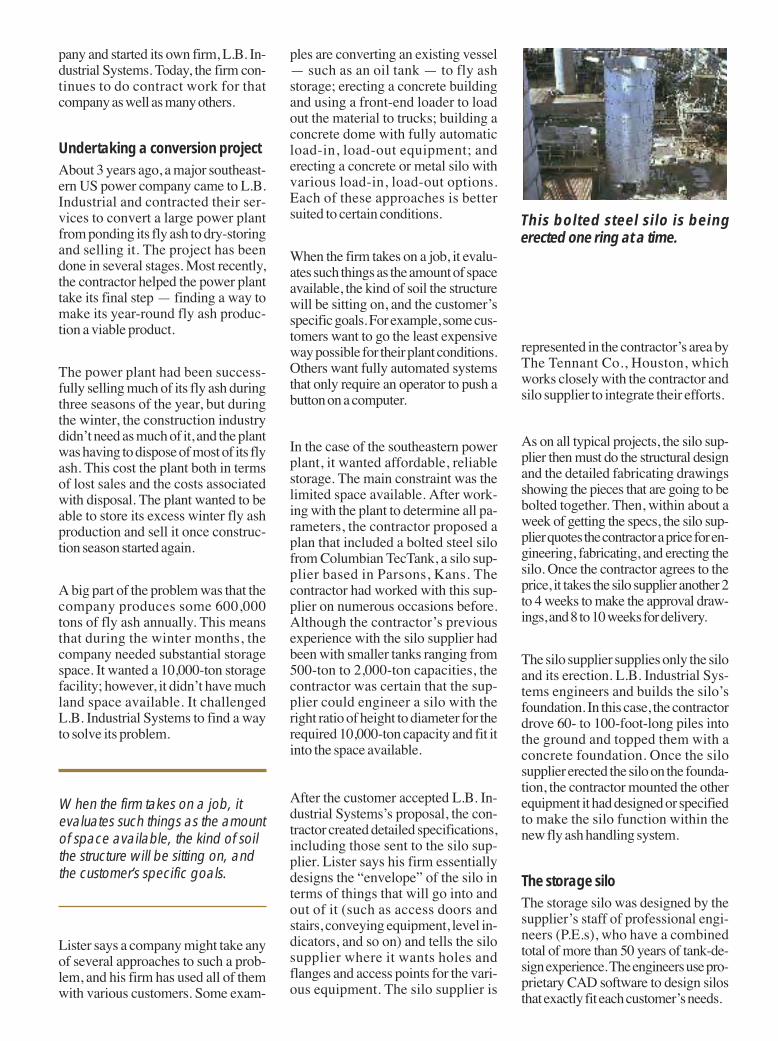
This bolted steel silo is beingerected one ring at a time.
The 10,000-ton-capacity storage silois a bolted steel tank 65 feet in diame-ter and a little more than 100 feet tall.It’s made up of multiple factory-coated flanged panels with bolt holesaround all four edges. Each plate hasa slight curve, designed to preciselyfit the specified silo’s curvature. Au-tomated production equipment en-sures that bolt holes and flanges willline up perfectly and that the panelsshare a uniform curvature.
The baked-on interior and exterior coat-ings protect the panels from abrasion,corrosion, and environmental damage.Because the coatings are applied in thefactory, the silo erection can take placein nearly any kind of weather, shorten-ing the required erection time.
Once the silo parts were delivered tothe site, the supplier erected the tankon the foundation the contractor hadprepared. All that was needed was toadd gaskets to the flanges, then boltthem together. The erection is doneone ring at a time. “The supplier doesscaffolding that’s supported by thelower rings as they go up,” says Lister.
“In the construction business,predictability is worth a lot ofmoney. That’s why manycompanies choose these silos.”
Allen Rogers, president of The Ten-nant Co., says that the supplier’s siloscan be delivered and erected relativelyquickly on a predictable schedule.”(Welded silos generally have to becoated in the field after they’ve beenwelded, and concrete structures usu-ally can’t be built during wet weather,making these structures’ erectionschedules somewhat less predictable.)Rogers says, “In the construction busi-ness, predictability is worth a lot ofmoney. That’s why many companieschoose these silos. They’re not cookie-cutter, but they’re predictable.”
Operating the fly ash handlingsystemIn operation, the power plant dis-charges its fly ash to three 1,000-ton-capacity loadout silos. When thesefill, the fly ash is blown into the10,000-ton-capacity storage silo. As aloadout silo’s material level de-creases, material is removed from thestorage silo via a vacuum extractionsystem the contractor designed andsent to the available loadout silo.
“We did a comprehensive study on thebest way to get ash out of big silos,”says Lister. “We found the best waywas a fluidized-zone floor system.We’ve divided the silo’s concrete floorinto several zones, each containing anaeration pod. When it’s time to unloadthe silo, air enters a pod and fluidizesthe material above it. A stationarynozzle similar to those used to unloadbig ships sucks the fluidized fly ashout of the fluidized zone. Piping at-tached to the nozzle drops the fly ashinto a vacuum collector. Then anotherpod is fluidized and a nozzle sucks outthe material from that zone. Thisprocess continues until the requiredamount has been removed. When thecollector vessel is full, a valve opens toa pressure vessel below the vacuumcollector and material flows by grav-ity into it. Then that valve closes and acompressor pressurizes the pressurevessel (also called a transfer vessel).The pressure blows the fly ash over toa loadout silo.”
Lister says the unloading system is aneconomical design because it allowsthe silo to be placed on the ground in-stead of up in the air, making vesselsupport easier than if the silo were de-signed to stand on legs.
Benefitting from the new systemThe new fly ash storage system hasbeen up and running since early 2005and has had no problems. L.B. Indus-trial Systems is pleased with the silo itchose and its supplier. “What we likeabout this company’s tanks,” Lister
says, “is the simplicity of their designand their ease of maintenance. We al-ways want to make things as easy aspossible for our customers and avoidinterruption of their process. We’vestayed with this silo supplier for manyyears because they make a good,well-engineered, economical tank,and they’re willing to help us fix anyproblems that might arise.”
Rogers agrees: “We’ve worked withthe supplier for many years. They’re avery creative company. They’re will-ing to think outside the box and findout what the customer actually wantsand then design the system that willaccomplish that.” PBE
Note: To find other articles on thistopic, look under “Storage” in Powderand Bulk Engineering’s comprehen-sive article index at www.powderbulk.com and in the December 2004issue.
Columbian TecTank, Parsons, KS620-421-0200www.columbiantectank.com
L.B. Industrial Systems, San Antonio, TX210-344-2009www.lbindustrialsystems.com
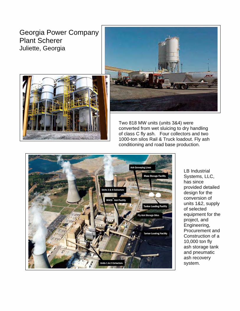
Georgia Power CompanyPlant SchererJuliette, Georgia
Two 818 MW units (units 3&4) wereconverted from wet sluicing to dry handlingof class C fly ash. Four collectors and two1000-ton silos Rail & Truck loadout. Fly ashconditioning and road base production.
LB IndustrialSystems, LLC,has sinceprovided detaileddesign for theconversion ofunits 1&2, supplyof selectedequipment for theproject, andEngineering,Procurement andConstruction of a10,000 ton flyash storage tankand pneumaticash recoverysystem.
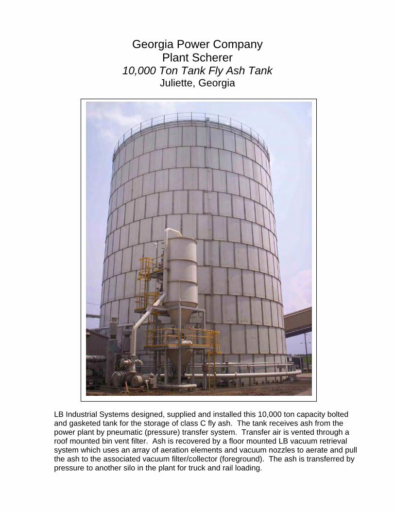
Georgia Power Company
Plant Scherer 10,000 Ton Tank Fly Ash Tank
Juliette, Georgia
LB Industrial Systems designed, supplied and installed this 10,000 ton capacity bolted and gasketed tank for the storage of class C fly ash. The tank receives ash from the power plant by pneumatic (pressure) transfer system. Transfer air is vented through a roof mounted bin vent filter. Ash is recovered by a floor mounted LB vacuum retrieval system which uses an array of aeration elements and vacuum nozzles to aerate and pull the ash to the associated vacuum filter/collector (foreground). The ash is transferred by pressure to another silo in the plant for truck and rail loading.
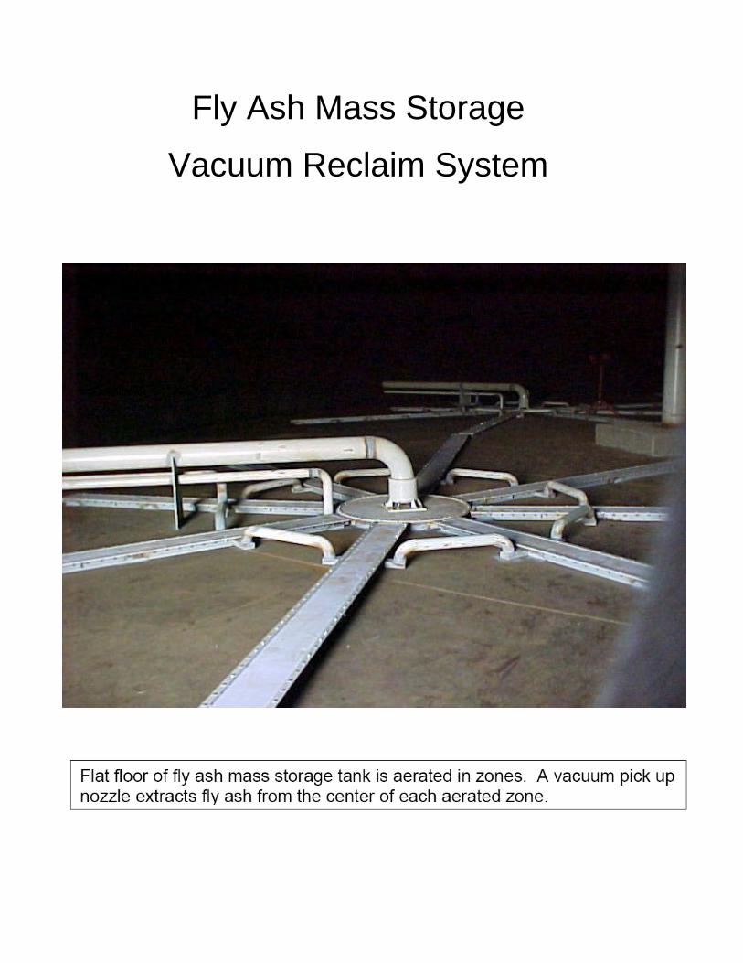
Fly Ash Mass Storage
Vacuum Reclaim System
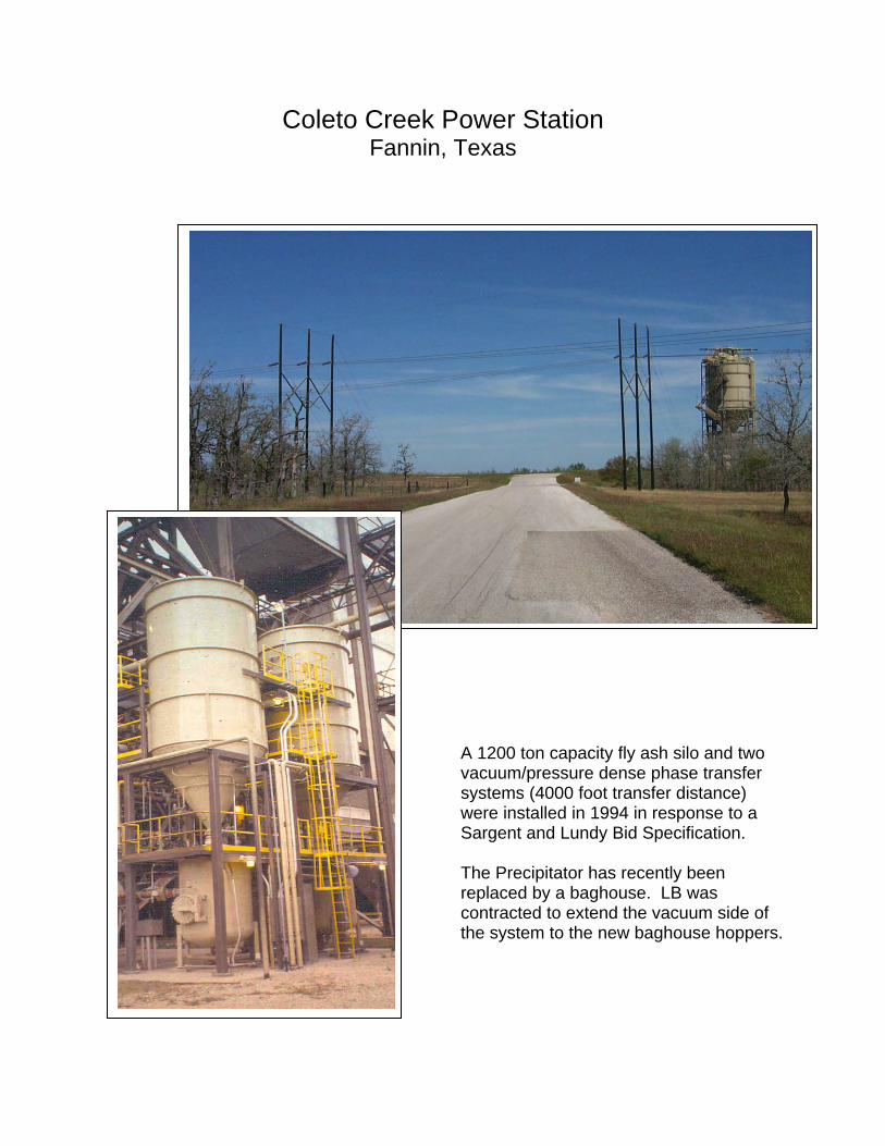
Coleto Creek Power Station Fannin, Texas
A 1200 ton capacity fly ash silo and two vacuum/pressure dense phase transfer systems (4000 foot transfer distance) were installed in 1994 in response to a Sargent and Lundy Bid Specification. The Precipitator has recently been replaced by a baghouse. LB was contracted to extend the vacuum side of the system to the new baghouse hoppers.
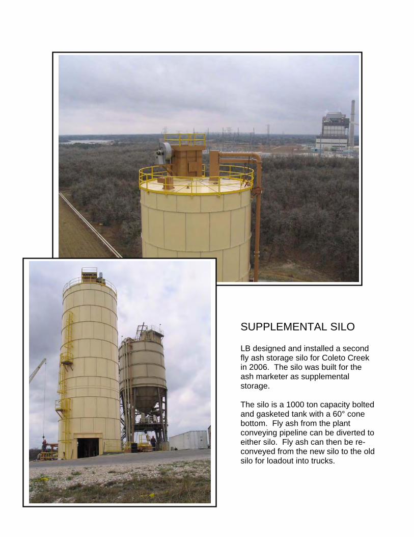
SUPPLEMENTAL SILO LB designed and installed a second fly ash storage silo for Coleto Creek in 2006. The silo was built for the ash marketer as supplemental storage. The silo is a 1000 ton capacity bolted and gasketed tank with a 60° cone bottom. Fly ash from the plant conveying pipeline can be diverted to either silo. Fly ash can then be re-conveyed from the new silo to the old silo for loadout into trucks.
Duke Energy CompanyBelews Creek
Walnut Cove, North Carolina
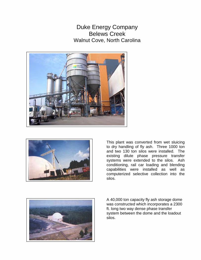
This plant was converted from wet sluicingto dry handling of fly ash. Three 1000 tonand two 130 ton silos were installed. Theexisting dilute phase pressure transfersystems were extended to the silos. Ashconditioning, rail car loading and blendingcapabilities were installed as well ascomputerized selective collection into thesilos.
A 40,000 ton capacity fly ash storage domewas constructed which incorporates a 2300ft. long two way dense phase transfersystem between the dome and the loadoutsilos.
Mississippi Power CompanyPlant Jack WatsonGulfport, Mississippi
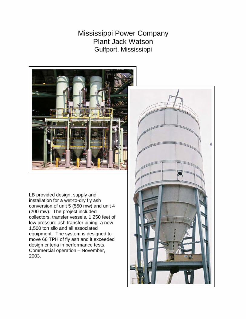
LB provided design, supply andinstallation for a wet-to-dry fly ashconversion of unit 5 (550 mw) and unit 4(200 mw). The project includedcollectors, transfer vessels, 1,250 feet oflow pressure ash transfer piping, a new1,500 ton silo and all associatedequipment. The system is designed tomove 66 TPH of fly ash and it exceededdesign criteria in performance tests.Commercial operation – November,2003.
Georgia Power Company Plant Bowen Cartersville, Georgia
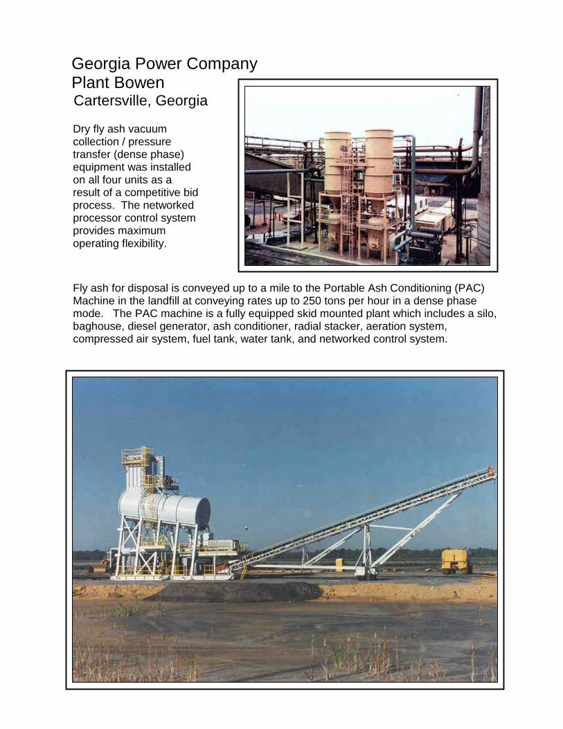
Dry fly ash vacuumcollection / pressuretransfer (dense phase)equipment was installedon all four units as aresult of a competitive bidprocess. The networkedprocessor control systemprovides maximumoperating flexibility.
Fly ash for disposal is conveyed up to a mile to the Portable Ash Conditioning (PAC)Machine in the landfill at conveying rates up to 250 tons per hour in a dense phasemode. The PAC machine is a fully equipped skid mounted plant which includes a silo,baghouse, diesel generator, ash conditioner, radial stacker, aeration system,compressed air system, fuel tank, water tank, and networked control system.

Alabama Power Company
Plant GadsdenGadsden , Alabama
LB industrial Systems provided engineering, procurement and construction for the wet-to-dry fly ash conversion of Plant Gadsden. The project included a 500-ton dry ash silo, vacuum collector and airlock, new vacuum pump, fly ash conditioner, truck scale, foundations, piping, electrical and instrumentation. The system is designed for 20 tph of dry ash collection from two precipitators, one on the powerhouse roof and one at ground level. The ash conditioner is designed to process 50 tph of ash.
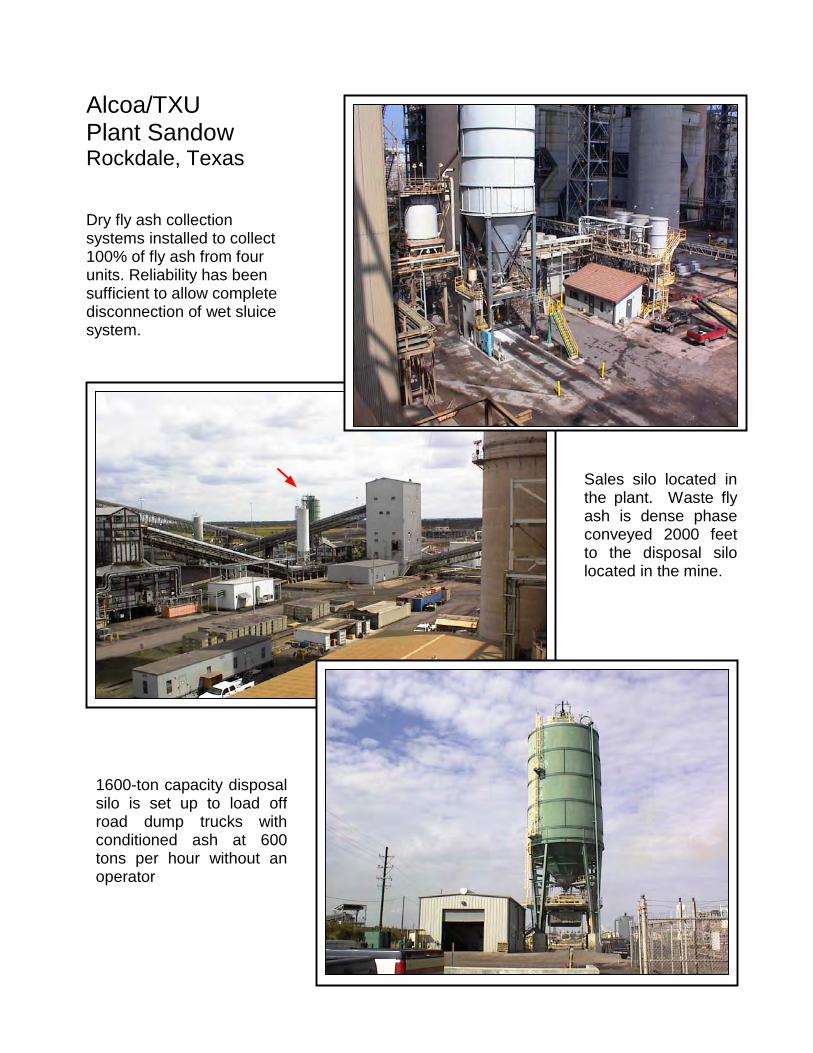
Sales silo located inthe plant. Waste flyash is dense phaseconveyed 2000 feetto the disposal silolocated in the mine.
1600-ton capacity disposalsilo is set up to load offroad dump trucks withconditioned ash at 600tons per hour without anoperator
Dry fly ash collectionsystems installed to collect100% of fly ash from fourunits. Reliability has beensufficient to allow completedisconnection of wet sluicesystem.
Alcoa/TXUPlant SandowRockdale, Texas
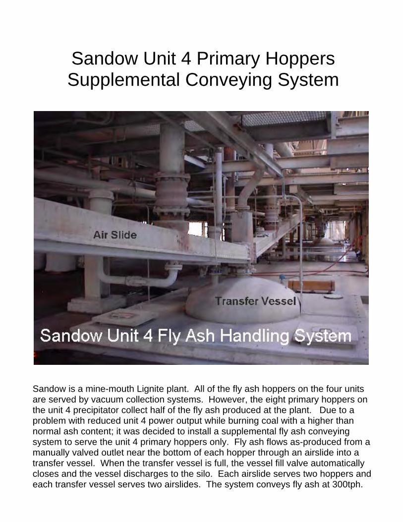
Sandow Unit 4 Primary Hoppers Supplemental Conveying System
Sandow is a mine-mouth Lignite plant. All of the fly ash hoppers on the four units are served by vacuum collection systems. However, the eight primary hoppers on the unit 4 precipitator collect half of the fly ash produced at the plant. Due to a problem with reduced unit 4 power output while burning coal with a higher than normal ash content; it was decided to install a supplemental fly ash conveying system to serve the unit 4 primary hoppers only. Fly ash flows as-produced from a manually valved outlet near the bottom of each hopper through an airslide into a transfer vessel. When the transfer vessel is full, the vessel fill valve automatically closes and the vessel discharges to the silo. Each airslide serves two hoppers and each transfer vessel serves two airslides. The system conveys fly ash at 300tph.
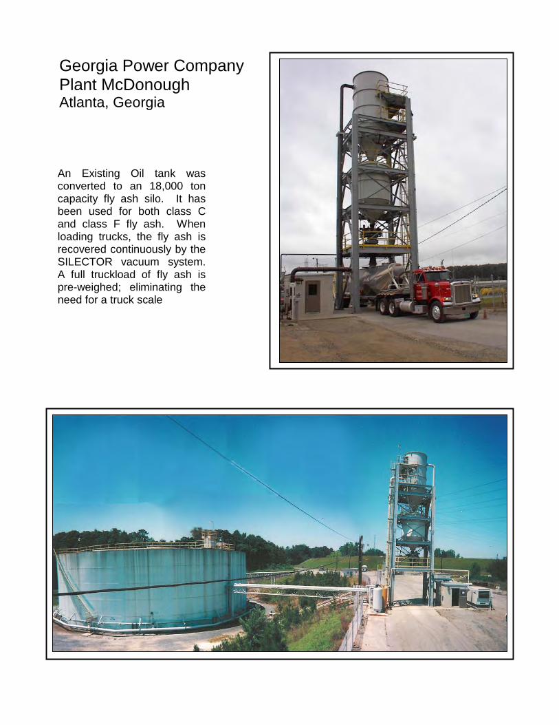
An Existing Oil tank wasconverted to an 18,000 toncapacity fly ash silo. It hasbeen used for both class Cand class F fly ash. Whenloading trucks, the fly ash isrecovered continuously by theSILECTOR vacuum system.A full truckload of fly ash ispre-weighed; eliminating theneed for a truck scale
Georgia Power CompanyPlant McDonoughAtlanta, Georgia
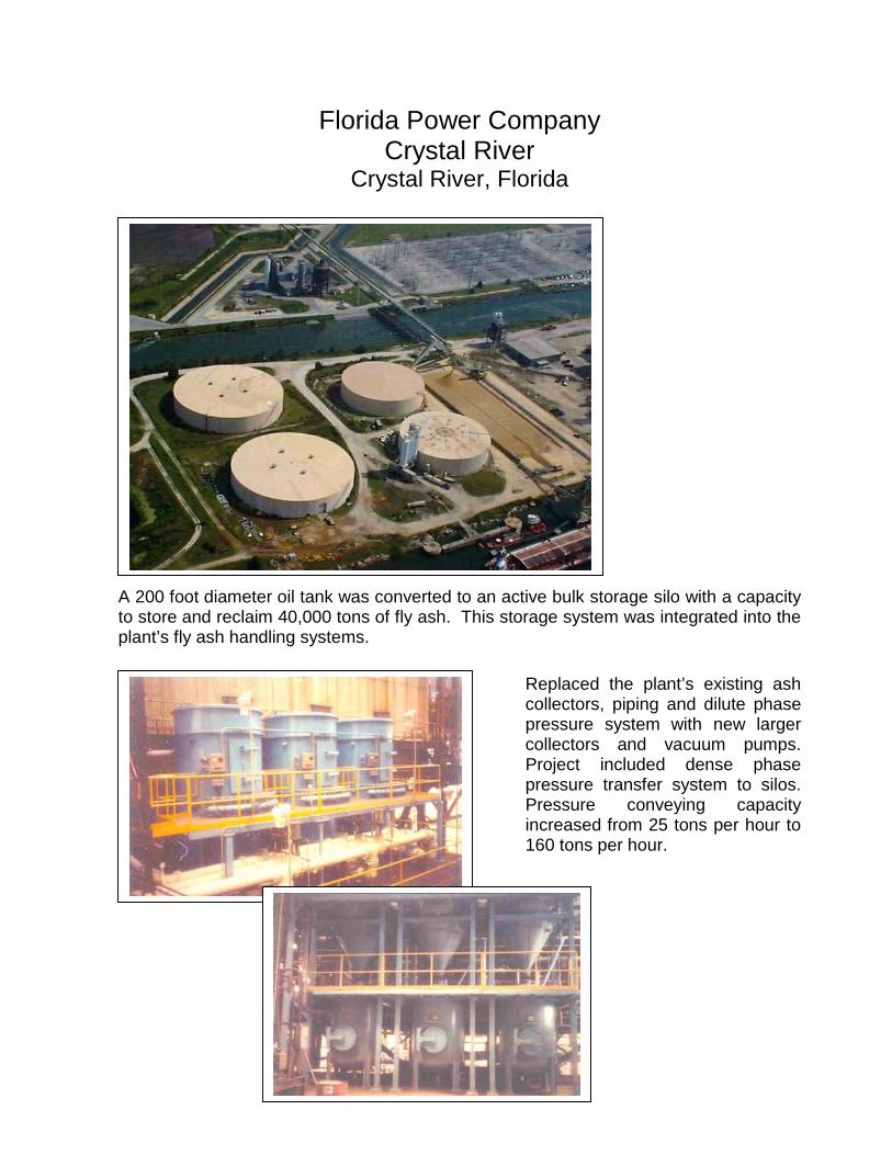
Florida Power CompanyCrystal River
Crystal River, Florida
A 200 foot diameter oil tank was converted to an active bulk storage silo with a capacityto store and reclaim 40,000 tons of fly ash. This storage system was integrated into theplant’s fly ash handling systems.
Replaced the plant’s existing ashcollectors, piping and dilute phasepressure system with new largercollectors and vacuum pumps.Project included dense phasepressure transfer system to silos.Pressure conveying capacityincreased from 25 tons per hour to160 tons per hour.
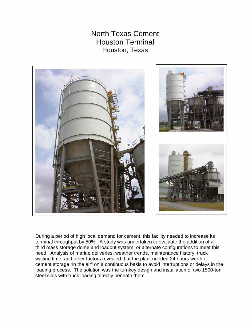
North Texas CementHouston Terminal
Houston, Texas
During a period of high local demand for cement, this facility needed to increase itsterminal throughput by 50%. A study was undertaken to evaluate the addition of athird mass storage dome and loadout system, or alternate configurations to meet thisneed. Analysis of marine deliveries, weather trends, maintenance history, truckwaiting time, and other factors revealed that the plant needed 24 hours worth ofcement storage “in the air” on a continuous basis to avoid interruptions or delays in theloading process. The solution was the turnkey design and installation of two 1500-tonsteel silos with truck loading directly beneath them.
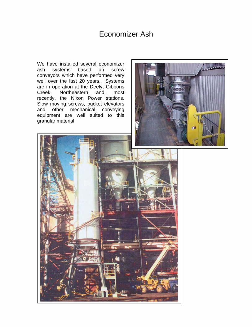
Economizer Ash We have installed several economizer ash systems based on screw conveyors which have performed very well over the last 20 years. Systems are in operation at the Deely, Gibbons Creek, Northeastern and, most recently, the Nixon Power stations. Slow moving screws, bucket elevators and other mechanical conveying equipment are well suited to this granular material
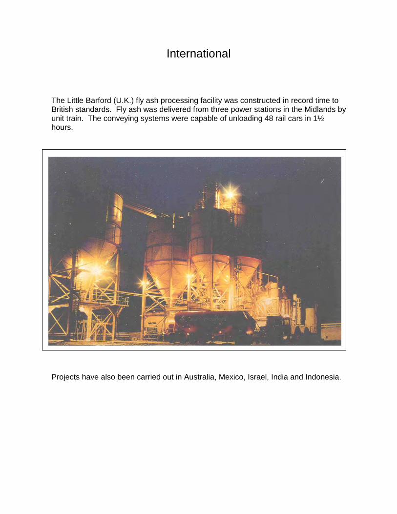
International
The Little Barford (U.K.) fly ash processing facility was constructed in record time toBritish standards. Fly ash was delivered from three power stations in the Midlands byunit train. The conveying systems were capable of unloading 48 rail cars in 1½hours.
Projects have also been carried out in Australia, Mexico, Israel, India and Indonesia.
140 Heimer Road, Suite 500 San Antonio, Texas 78232 Phone: (210) 344-2009 Fax: (210) 344-1121 Website: www.lbindustrialsystems.com Contact: [email protected]
Please direct inquires to:
Gary W. Beckcom President, CEO/ Projects Development [email protected]
Richard J. Didelot Manager, Sales
Mark S. Konzal Manager, Business Development