Embed Size (px)
Citation preview
Rapid Sample Introduction SystemQuick Installation Guide
Manual Part Number 610092 Rev 8
ASXPRESS ®
PLUS
ASXPRESS PLUS Quick Installation Guide
2
ASXPRESS PLUS Quick Installation GuideYou can and should arrange for expert installation of the ASXPRESS PLUS Rapid Sample Introduction System.Installation services from CETAC or an authorized provider ensure that the autosampler is properly prepared and that the installation is customized for your application.
If you are doing the installation yourself, this guide will show you how to connect the ASXPRESS PLUS Rapid Sample Introduction System to a CETAC autosampler. If your autosampler is not new, the autosampler may need additional preparation as described in the ASXPRESS PLUS Operator’s Manual, which is available on the software CD or from www.cetac.com. Also note that many applications may require modifications to the rinse pump arrangement or to timing parameters, also described in the Operator’s Manual.
Photos in this guide show different, representative models of the autosampler and other parts of the ASXPRESS PLUS system.
This guide is for use by qualified chemists or laboratory technicians who are familiar with electrical and chemical safety precautions. See the ASXPRESS PLUS Operator’s Manual for notices and safety information.
1 Unpack the ASXPRESS PLUS components and the CETAC autosampler. Note:
Inspect all packaging materials for damage that may have occurred during shipment.
Refer to the packing lists included with both the ASXPRESS PLUSand autosampler to ensure that all components have been received.
Keep all shipping containers for use in the unlikely event that shipment is required for warranty or service work. The original packaging must be used for this purpose to ensure that the warranty remains valid.
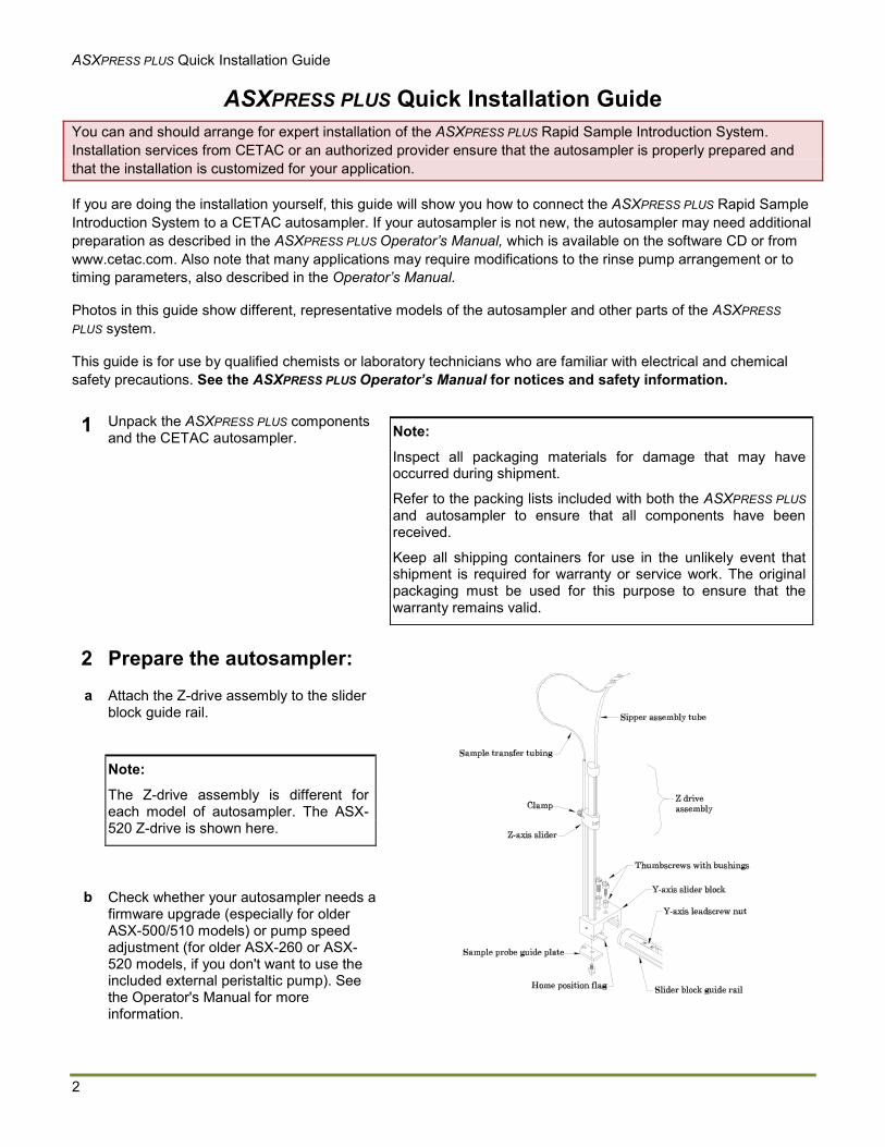
2 Prepare the autosampler:a Attach the Z-drive assembly to the slider
block guide rail.
Note:
The Z-drive assembly is different for each model of autosampler. The ASX-520 Z-drive is shown here.
b Check whether your autosampler needs a firmware upgrade (especially for older ASX-500/510 models) or pump speed adjustment (for older ASX-260 or ASX-520 models, if you don't want to use the included external peristaltic pump). See the Operator's Manual for more information.
ASXPRESS PLUS Quick Installation Guide
3
c Install the Xpress rinse station which is supplied with the upgrade kit.
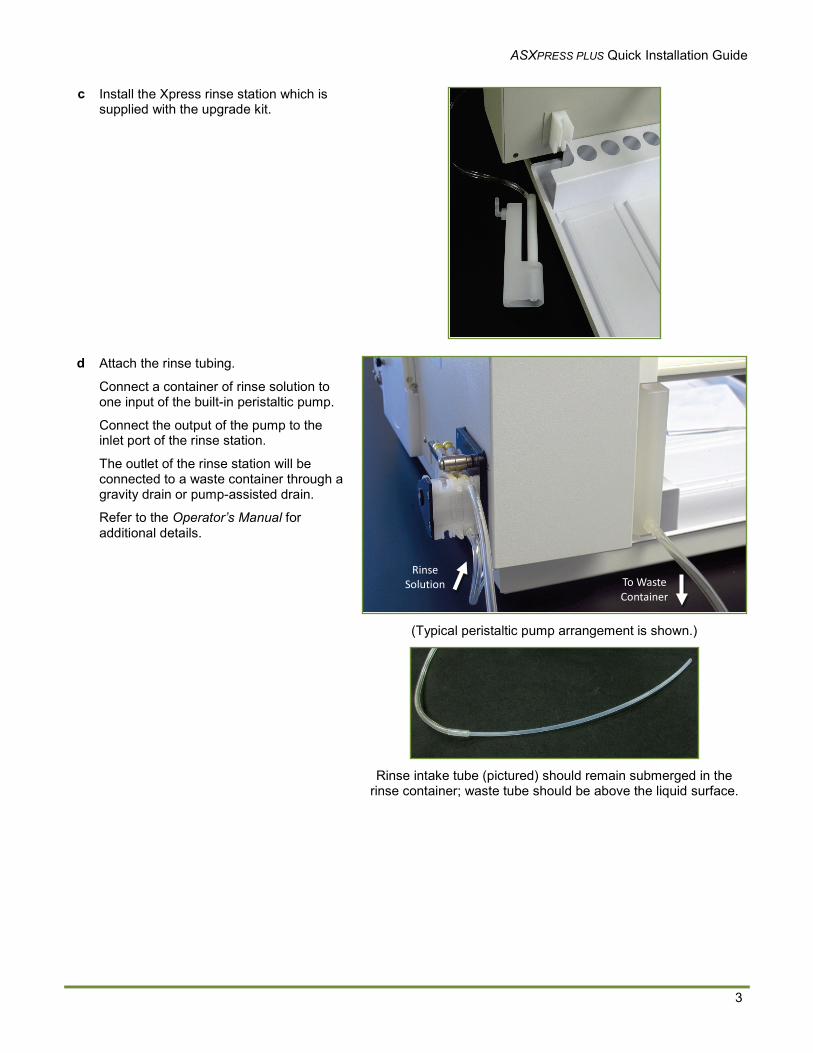
d Attach the rinse tubing.
Connect a container of rinse solution to one input of the built-in peristaltic pump.
Connect the output of the pump to the inlet port of the rinse station.
The outlet of the rinse station will be connected to a waste container through a gravity drain or pump-assisted drain.
Refer to the Operator’s Manual for additional details.
(Typical peristaltic pump arrangement is shown.)
Rinse intake tube (pictured) should remain submerged in the rinse container; waste tube should be above the liquid surface.
Rinse Solution To Waste
Container
ASXPRESS PLUS Quick Installation Guide
4
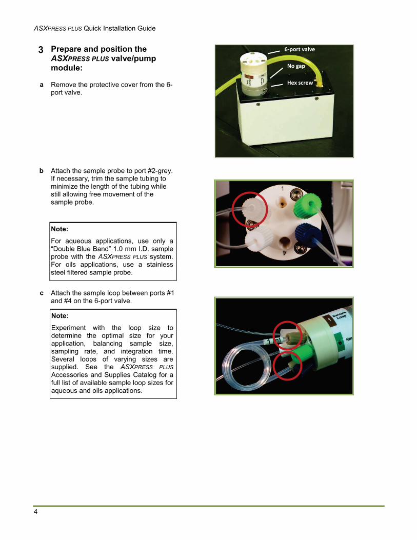
3 Prepare and position the ASXPRESS PLUS valve/pump module:
a Remove the protective cover from the 6-port valve.
b Attach the sample probe to port #2-grey.If necessary, trim the sample tubing to minimize the length of the tubing while still allowing free movement of the sample probe.
Note:
For aqueous applications, use only a “Double Blue Band” 1.0 mm I.D. sample probe with the ASXPRESS PLUS system.For oils applications, use a stainless steel filtered sample probe.
c Attach the sample loop between ports #1 and #4 on the 6-port valve.
Note:
Experiment with the loop size to determine the optimal size for your application, balancing sample size, sampling rate, and integration time.Several loops of varying sizes are supplied. See the ASXPRESS PLUSAccessories and Supplies Catalog for a full list of available sample loop sizes for aqueous and oils applications.
Hex screw
No gap
6-port valve
ASXPRESS PLUS Quick Installation Guide
5
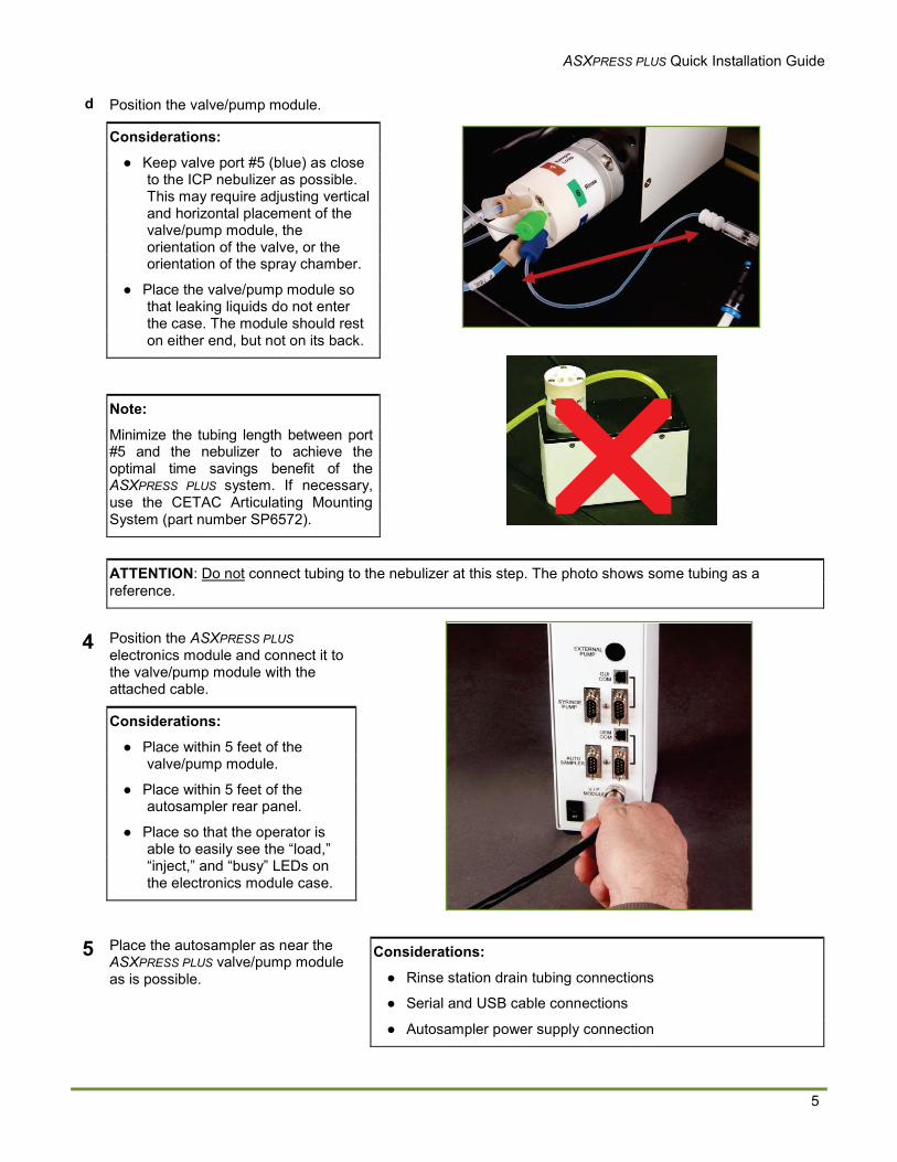
d Position the valve/pump module.
Considerations:
● Keep valve port #5 (blue) as close to the ICP nebulizer as possible. This may require adjusting vertical and horizontal placement of the valve/pump module, the orientation of the valve, or the orientation of the spray chamber.
● Place the valve/pump module so that leaking liquids do not enter the case. The module should rest on either end, but not on its back.
Note:
Minimize the tubing length between port #5 and the nebulizer to achieve the optimal time savings benefit of the ASXPRESS PLUS system. If necessary, use the CETAC Articulating Mounting System (part number SP6572).
ATTENTION: Do not connect tubing to the nebulizer at this step. The photo shows some tubing as a reference.
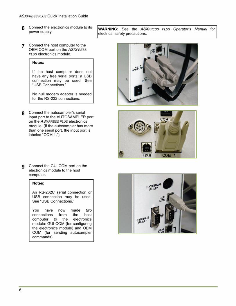
4 Position the ASXPRESS PLUSelectronics module and connect it to the valve/pump module with the attached cable.
Considerations:
● Place within 5 feet of the valve/pump module.
● Place within 5 feet of the autosampler rear panel.
● Place so that the operator is able to easily see the “load,” “inject,” and “busy” LEDs on the electronics module case.
5 Place the autosampler as near the ASXPRESS PLUS valve/pump module as is possible.
Considerations:
● Rinse station drain tubing connections
● Serial and USB cable connections
● Autosampler power supply connection
ASXPRESS PLUS Quick Installation Guide
6
6 Connect the electronics module to its power supply.
WARNING: See the ASXPRESS PLUS Operator’s Manual for electrical safety precautions.
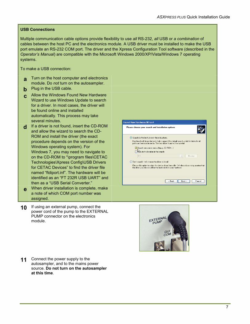
7 Connect the host computer to the OEM COM port on the ASXPRESS PLUS electronics module.
Notes:
If the host computer does not have any free serial ports, a USB connection may be used. See “USB Connections.”
No null modem adapter is needed for the RS-232 connections.
8 Connect the autosampler’s serial input port to the AUTOSAMPLER port on the ASXPRESS PLUS electronics module. (If the autosampler has more than one serial port, the input port is labeled “COM 1.”)
9 Connect the GUI COM port on the electronics module to the host computer.
Notes:
An RS-232C serial connection or USB connection may be used. See “USB Connections.”
You have now made twoconnections from the host computer to the electronics module: GUI COM (for configuring the electronics module) and OEM COM (for sending autosampler commands).
ASXPRESS PLUS Quick Installation Guide
7
USB Connections
Multiple communication cable options provide flexibility to use all RS-232, all USB or a combination of cables between the host PC and the electronics module. A USB driver must be installed to make the USB port emulate an RS-232 COM port. The driver and the Xpress Configuration Tool software (described in the Operator’s Manual) are compatible with the Microsoft Windows 2000/XP/Vista/Windows 7 operating systems.
To make a USB connection:
a Turn on the host computer and electronics module. Do not turn on the autosampler.
b Plug in the USB cable.
c Allow the Windows Found New Hardware Wizard to use Windows Update to search for a driver. In most cases, the driver will be found online and installed automatically. This process may take several minutes.
d If a driver is not found, insert the CD-ROM and allow the wizard to search the CD-ROM and install the driver (the exact procedure depends on the version of the Windows operating system). For Windows 7, you may need to navigate to on the CD-ROM to “\program files\CETAC Technologies\Xpress Config\USB Drivers for CETAC Devices” to find the driver file named “ftdiport.inf”. The hardware will be identified as an “FT 232R USB UART” and then as a “USB Serial Converter.”
e When driver installation is complete, make a note of which COM port number was assigned.
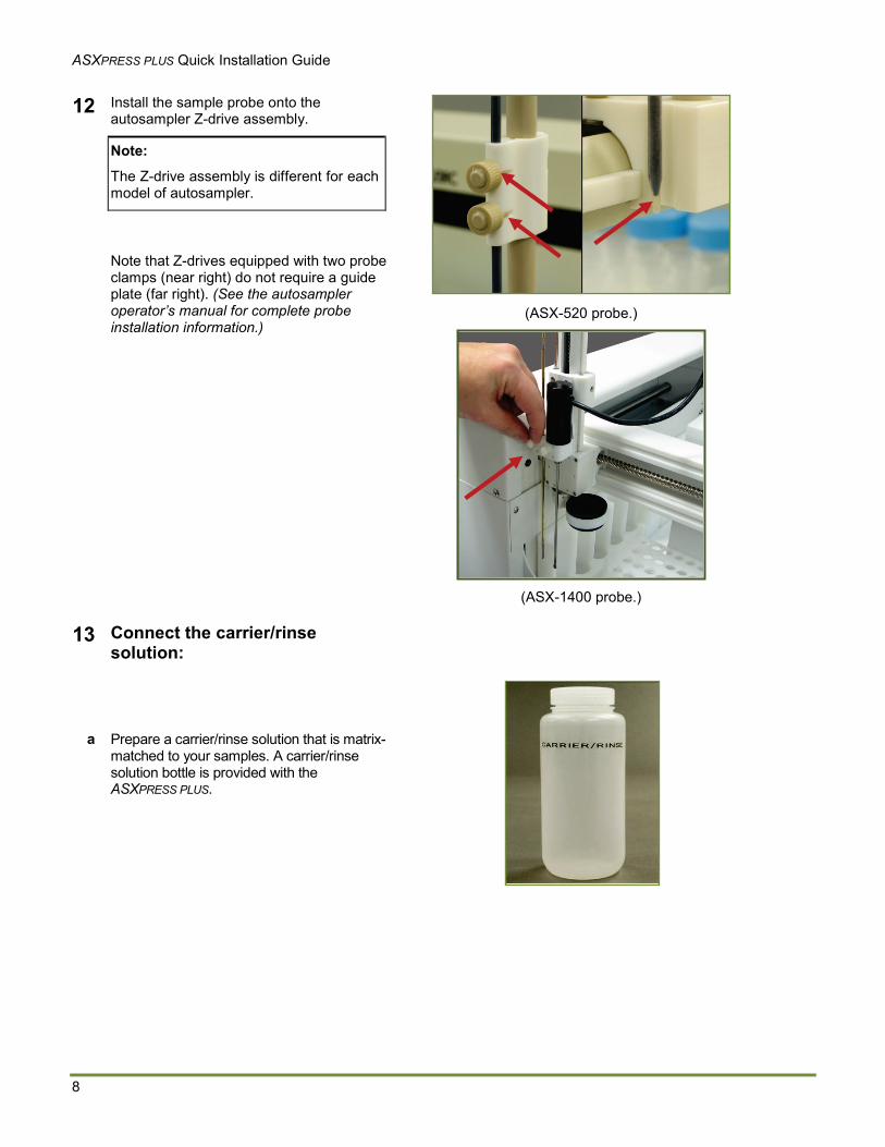
10 If using an external pump, connect the power cord of the pump to the EXTERNAL PUMP connector on the electronics module.
11 Connect the power supply to the autosampler, and to the mains power source. Do not turn on the autosampler at this time.
ASXPRESS PLUS Quick Installation Guide
8
12 Install the sample probe onto the autosampler Z-drive assembly.
Note:
The Z-drive assembly is different for each model of autosampler.
Note that Z-drives equipped with two probe clamps (near right) do not require a guide plate (far right). (See the autosampler operator’s manual for complete probe installation information.)
(ASX-520 probe.)
(ASX-1400 probe.)
13 Connect the carrier/rinse solution:
a Prepare a carrier/rinse solution that is matrix-matched to your samples. A carrier/rinse solution bottle is provided with the ASXPRESS PLUS.
ASXPRESS PLUS Quick Installation Guide
9
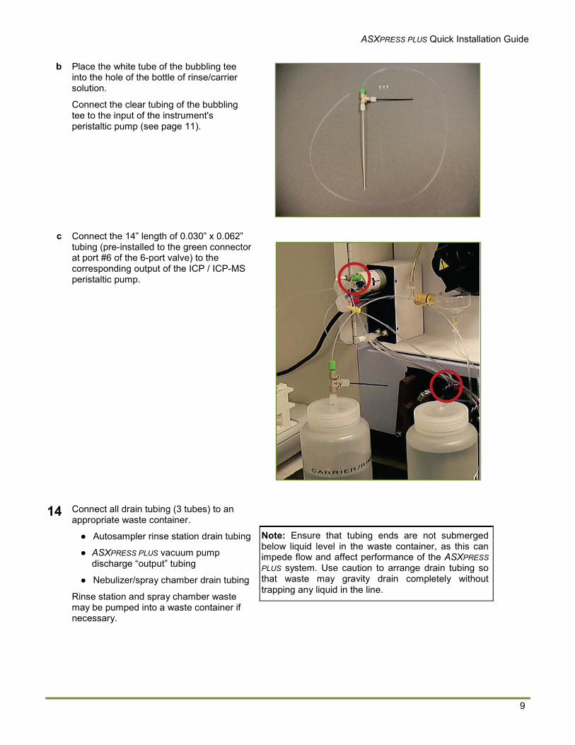
b Place the white tube of the bubbling tee into the hole of the bottle of rinse/carrier solution.
Connect the clear tubing of the bubbling tee to the input of the instrument's peristaltic pump (see page 11).
c Connect the 14” length of 0.030” x 0.062” tubing (pre-installed to the green connector at port #6 of the 6-port valve) to the corresponding output of the ICP / ICP-MS peristaltic pump.
14 Connect all drain tubing (3 tubes) to an appropriate waste container.
● Autosampler rinse station drain tubing
● ASXPRESS PLUS vacuum pump discharge “output” tubing
● Nebulizer/spray chamber drain tubing
Rinse station and spray chamber waste may be pumped into a waste container if necessary.
Note: Ensure that tubing ends are not submerged below liquid level in the waste container, as this can impede flow and affect performance of the ASXPRESS PLUS system. Use caution to arrange drain tubing so that waste may gravity drain completely without trapping any liquid in the line.
ASXPRESS PLUS Quick Installation Guide
10
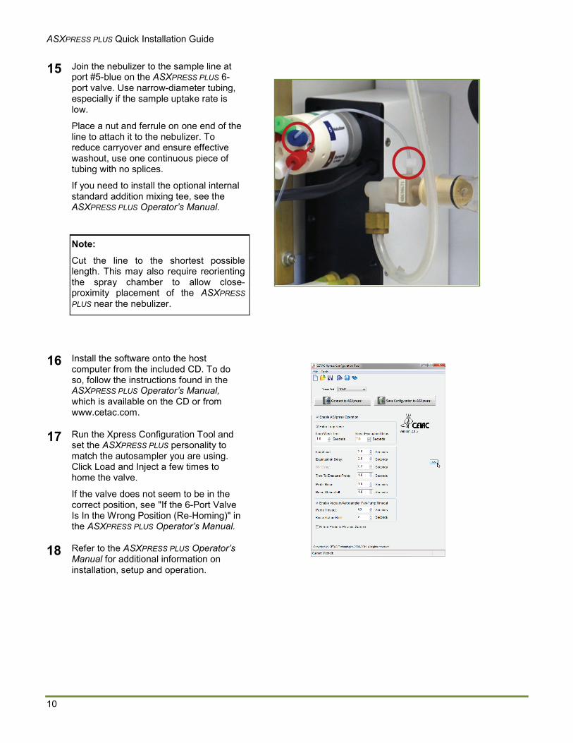
15 Join the nebulizer to the sample line at port #5-blue on the ASXPRESS PLUS 6-port valve. Use narrow-diameter tubing, especially if the sample uptake rate is low.
Place a nut and ferrule on one end of the line to attach it to the nebulizer. To reduce carryover and ensure effective washout, use one continuous piece of tubing with no splices.
If you need to install the optional internal standard addition mixing tee, see the ASXPRESS PLUS Operator’s Manual.
Note:
Cut the line to the shortest possible length. This may also require reorienting the spray chamber to allow close-proximity placement of the ASXPRESS PLUS near the nebulizer.
16 Install the software onto the host computer from the included CD. To do so, follow the instructions found in the ASXPRESS PLUS Operator’s Manual, which is available on the CD or from www.cetac.com.
17 Run the Xpress Configuration Tool and set the ASXPRESS PLUS personality to match the autosampler you are using.Click Load and Inject a few times to home the valve.
If the valve does not seem to be in the correct position, see "If the 6-Port Valve Is In the Wrong Position (Re-Homing)" in the ASXPRESS PLUS Operator’s Manual.
18 Refer to the ASXPRESS PLUS Operator’s Manual for additional information on installation, setup and operation.
ASXPRESS PLUS Quick Installation Guide
11
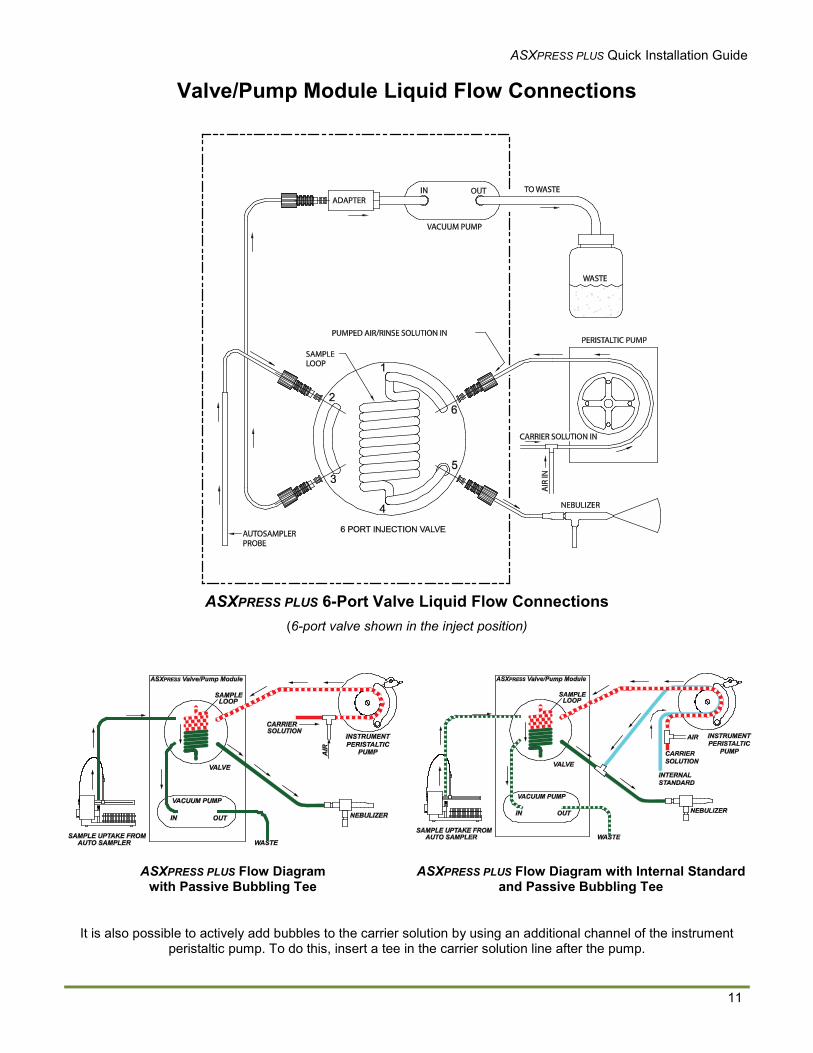
Valve/Pump Module Liquid Flow Connections
ASXPRESS PLUS 6-Port Valve Liquid Flow Connections(6-port valve shown in the inject position)
ASXPRESS PLUS Flow Diagram with Passive Bubbling Tee
ASXPRESS PLUS Flow Diagram with Internal Standardand Passive Bubbling Tee
It is also possible to actively add bubbles to the carrier solution by using an additional channel of the instrument peristaltic pump. To do this, insert a tee in the carrier solution line after the pump.
ASXPRESS PLUS Quick Installation Guide
12
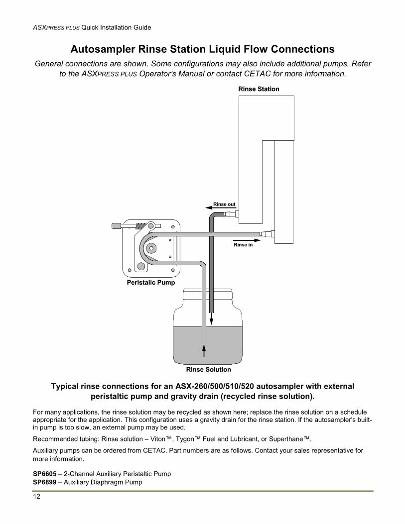
Autosampler Rinse Station Liquid Flow ConnectionsGeneral connections are shown. Some configurations may also include additional pumps. Refer
to the ASXPRESS PLUS Operator’s Manual or contact CETAC for more information.
Typical rinse connections for an ASX-260/500/510/520 autosampler with external peristaltic pump and gravity drain (recycled rinse solution).
For many applications, the rinse solution may be recycled as shown here; replace the rinse solution on a schedule appropriate for the application. This configuration uses a gravity drain for the rinse station. If the autosampler's built-in pump is too slow, an external pump may be used.
Recommended tubing: Rinse solution – Viton™, Tygon™ Fuel and Lubricant, or Superthane™.
Auxiliary pumps can be ordered from CETAC. Part numbers are as follows. Contact your sales representative for more information.
SP6605 – 2-Channel Auxiliary Peristaltic PumpSP6899 – Auxiliary Diaphragm Pump
ASXPRESS PLUS Quick Installation Guide
13
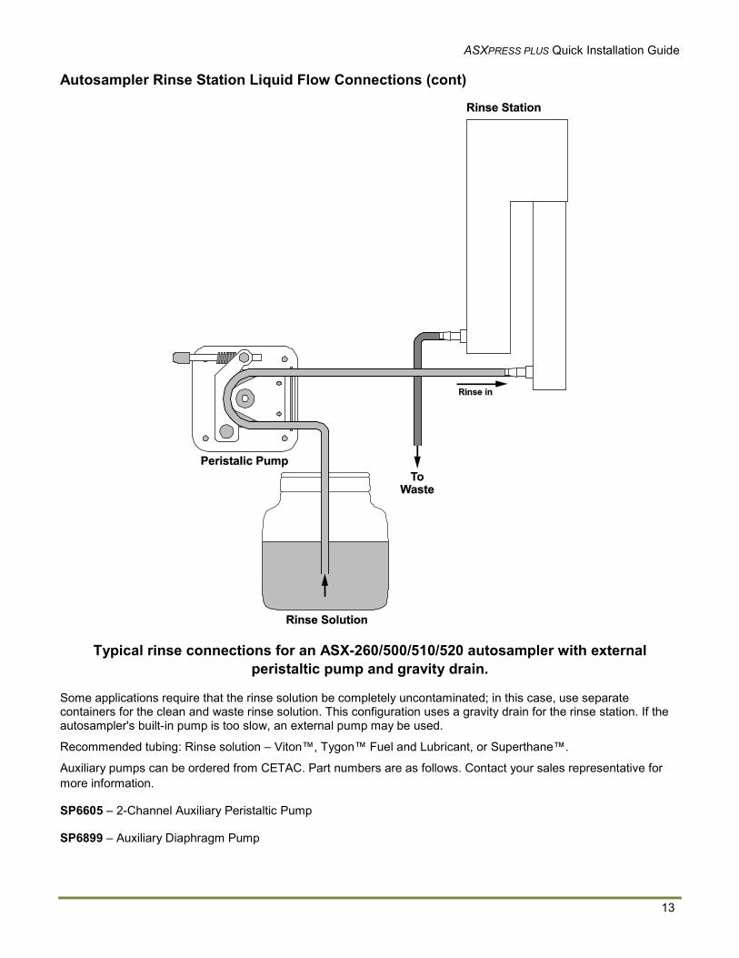
Autosampler Rinse Station Liquid Flow Connections (cont)
Typical rinse connections for an ASX-260/500/510/520 autosampler with external peristaltic pump and gravity drain.
Some applications require that the rinse solution be completely uncontaminated; in this case, use separate containers for the clean and waste rinse solution. This configuration uses a gravity drain for the rinse station. If the autosampler's built-in pump is too slow, an external pump may be used.
Recommended tubing: Rinse solution – Viton™, Tygon™ Fuel and Lubricant, or Superthane™.
Auxiliary pumps can be ordered from CETAC. Part numbers are as follows. Contact your sales representative for more information.
SP6605 – 2-Channel Auxiliary Peristaltic Pump
SP6899 – Auxiliary Diaphragm Pump
ASXPRESS PLUS Quick Installation Guide
14
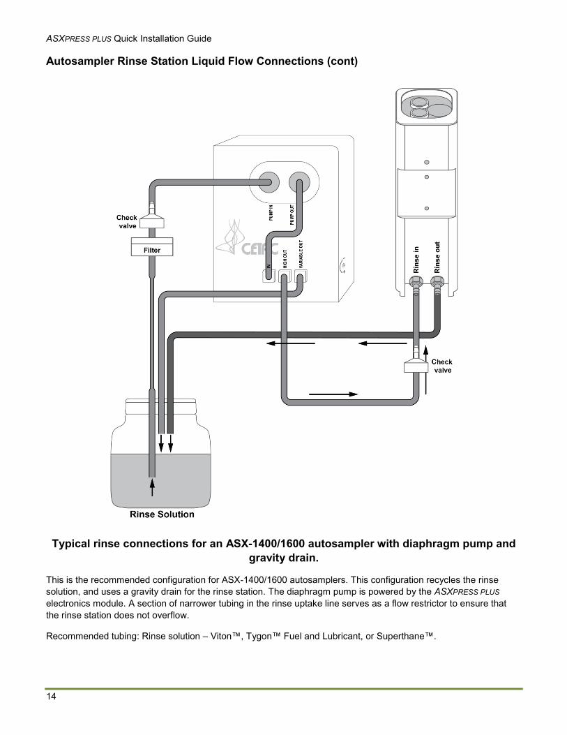
Autosampler Rinse Station Liquid Flow Connections (cont)
Typical rinse connections for an ASX-1400/1600 autosampler with diaphragm pump and gravity drain.
This is the recommended configuration for ASX-1400/1600 autosamplers. This configuration recycles the rinse solution, and uses a gravity drain for the rinse station. The diaphragm pump is powered by the ASXPRESS PLUSelectronics module. A section of narrower tubing in the rinse uptake line serves as a flow restrictor to ensure that the rinse station does not overflow.
Recommended tubing: Rinse solution – Viton™, Tygon™ Fuel and Lubricant, or Superthane™.
ASXPRESS PLUS Quick Installation Guide
15
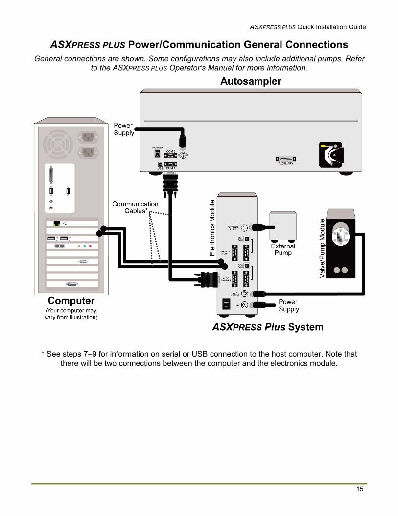
ASXPRESS PLUS Power/Communication General ConnectionsGeneral connections are shown. Some configurations may also include additional pumps. Refer
to the ASXPRESS PLUS Operator’s Manual for more information.
* See steps 7–9 for information on serial or USB connection to the host computer. Note that there will be two connections between the computer and the electronics module.

© 2010, 2011, 2013, 2015 Teledyne Technologies Inc , All rights reserved. / Printed in USA / 610092 rev 8Windows is a registered trademark of Microsoft Corporation in the United States and other countries. Tygon is a registered trademarks of Saint-Gobain Performance Plastics. DuPont™, Kapton®, Tefzel® and Viton® are trademarks or registered trademarks of E.I. du Pont de Nemours and Company.All other marks are the property of their respective owners.


![Quick Installation Guide – PS107 - SEH Technology · @ support@seh.de Print Server PS107 Quick Installation Guide Overview [en] This Quick Installation Guide provides a description](https://img.pdfslide.net/doc/110x75/60636d0038f9905e874fdfb6/quick-installation-guide-a-ps107-seh-technology-supportsehde-print-server.jpg)