Embed Size (px)
Citation preview
<ATC-Wake> <IST–2001-34729>
< D6_2: ATC-Wake – Integrated Wake Vortex Safety and Capacity system>
ATC-Wake: Integrated Wake Vortex Safety and Capacity System
(ATC Wake D6_2)
L.J.P. Speijker (NLR)
A. Vidal (EUROCONTROL)
F. Barbaresco (Thales AD)
T. Gerz (DLR)
H. Barny (Thales Avionics)
G. Winckelmans (UCL)
Report Version: Final
Report Preparation Date: 31/12/2005
Classification: Public
Contract Start Date: 01.07.2002
Duration: 31.12.2005
Project Co-ordinator: National Aerospace Laboratory NLR
Partners Deutsches Zentrum für Luft- & Raumfahrt DLR
EUROCONTROL Experimental Centre (EEC)
Thales Air Defence (TAD)
Thales Avionics (TAV)
Université Catholique de Louvain (UCL)
Project funded by the European Community under the “Information Society Technology” Programme (1998-2002)
ATC-WAKE D6_2, FINAL VERSION, 31/12/2005
II
DELIVERABLES SUMMARY SHEET
Project Number: IST-2001-34729
Project Acronym: ATC-Wake
Title: Integrated ATC Wake Vortex Safety and Capacity System
Deliverable N°: D6_2
Due date: 31/12/2005
Delivery Date: 31/12/2005 (Final Version)
Short Description:
The IST project ATC-Wake aims to develop an integrated system for ATC (Air Traffic Control) that would allow variable aircraft separation distances, as opposed to the fixed distances presently applied at airports. A variety of existing subsystems has been integrated within the ATC-Wake Integrated Platform, which was used in a test bed environment role: • To evaluate the interoperability of the ATC-Wake system with existing ATC systems
currently used at various European airports; • To assess the safety and capacity improvements that can be obtained by local
installation of the ATC-Wake system at various European airports; • To evaluate operational usability and acceptability of the ATC-Wake system; • To make a plan and to assess the costs for further implementation and exploitation of
the ATC-Wake IP platform into the system that can be installed at European airports). The ATC-Wake Integrated Platform is an essential step that will lead to installation of an integrated ATC decision support system at airports, enabling air traffic controllers to apply new optimised weather based aircraft separation. The ATC-Wake system will integrate weather and Wake sensors, weather forecasting and now-casting systems, Wake vortex prediction system, separation mode planner, and air traffic controller interface. Used with new harmonised safety regulation, this system will provide tactical and strategic benefits, while maintaining safety. This Final Report provides an overview of all the activities performed, including conclusions and recommendations in order to continue the exploitation towards installation of the ATC-Wake system at European airports.
Partners owning: ATC-Wake Consortium
Partners contributed: ATC-Wake Consortium
Made available to: European Commission, IST Programme
ATC-WAKE D6_2, FINAL VERSION, 31/12/2005
III
Contract No. IST–2001-34729
ATCATCATCATC----Wake Wake Wake Wake WP6000WP6000WP6000WP6000
Task Title Integrated ATC Wake Vortex Safety and Capacity System
Deliverable D6_2
Prepared by: Lennaert Speijker (NLR)
Antoine Vidal (EUROCONTROL)
Frederic Barbaresco (Thales AD)
Thomas Gerz (DLR)
Hervé Barny (Thales Avionics)
Gregoire Winckelmans (UCL)
Document control sheet NLR-TP-2006-254
Work Package: WP 6000 Released by: L.J.P. Speijke r (NLR)
Version: Final Approved by : L.J.P. Speijker (NLR)
Issued by: NLR Reviewed by : ATC-Wake consortium
Date of issue: 31/12/2005
This report is Public, and has been produced by the ATC-Wake consortium: National Aerospace Laboratory NLR
Deutsches Zentrum für Luft- & Raumfahrt DLR
EUROCONTROL Experimental Centre (EEC)
Thales Air Defence (TAD)
Thales Avionics (TAV)
Université Catholique de Louvain (UCL)
ATC-WAKE D6_2, FINAL VERSION, 31/12/2005
IV
List of Acronyms
ACC Air traffic Control Centre (en route) AGL Altitude above Ground Level AMAN Arrival Manager APP Approach ATC Unit ARS Airport Radar System ATCO Air Traffic Control Officer ATIS Air Traffic Information Service ATSU Air Traffic Service Unit AVOL Aerodrome Visibility Operational Level CSPR Closely Spaced Parallel Runways DMAN Departure MANAGER DME Distance Measuring Equipment EAT Expected Approach Time ETA Estimated Time of Arrival FAP Final Approach Point FDPS Flight Data Processing System FIR Flight Information Region GND Ground Controller HMI Human Man Interface IAF Initial Approach Fix IAS Indicated Air Speed ILS Instrument Landing System IMC Instrument Meteorological Conditions INI Initial Approach Controller ITM Intermediate Approach Controller LDA Localizer Directional Aid ILS Instrument Landing System LVP Low Visibility Procedure MAP Missed Approach Point MLS Micro Wave Landing System MTOW Maximum Take-Off Weight NDB Non-Directional Beacon NM Nautical Mile NTZ Non Transgression Zone PRM Precision Radar Monitor ROT Runway Occupancy Time SART Situation Awareness Rating Technique SMR Surface Movement Radar SOIA Simultaneous Offset Instrument Approaches STAR Standard Arrival Route SUS System Usability Scale THR Runway Threshold TLX Task Load Index TMA Terminal Manoeuvring Area TWR Tower Controller UAC Upper Airspace Centre VFS Vortex Forecast System VHF Very High Frequency WP Work Package WV Wake Vortex
ATC-WAKE D6_2, FINAL VERSION, 31/12/2005
V
Executive Summary
The IST project ATC-Wake aims to develop an integrated system for ATC (Air Traffic
Control) that would allow variable aircraft separation distances, as opposed to the fixed
distances presently applied at airports. A variety of existing subsystems have been
integrated within the ATC-Wake Integrated Platform (IP), which was used: • To evaluate the interoperability of the ATC-Wake system with existing ATC systems
currently used at various European airports; • To assess the safety and capacity improvements that can be obtained by local
installation of the ATC-Wake system at various European airports; • To evaluate operational usability and acceptability of the ATC-Wake system; • To make a plan and to assess the costs for further implementation and exploitation of the
ATC-Wake IP platform into the system that can be installed at European airports).
This platform is an essential step that will lead to installation of an integrated ATC decision
support system at airports, enabling air traffic controllers to apply new optimised weather
based aircraft separation. The ATC-Wake system integrates weather and Wake sensors,
weather forecasting and now-casting systems, Wake vortex prediction system, separation
mode planner, and air traffic controller interfaces.
WP1: ATC-WAKE OPERATIONAL CONCEPT AND SYSTEM REQUIR EMENTS As a first step towards use of an ATC-Wake system at airports, the operational concept and
requirements for the application of reduced aircraft separation under favourable weather
conditions have been established. During the development and evaluation of the
requirements, a number of key issues have been identified for further analysis:
• Transitions between ATC-Wake and ICAO separation modes;
• Aircraft separation and sector loading;
• Missed approaches when ATC-Wake is applied;
• Evaluation of safety requirements;
• Evaluation of capacity benefits;
• Evaluation of operational feasibility;
• Assessment of the ATC-Wake system performance requirements;
• Potential use of WV instrumentation on-board aircraft (and down-linking of WV data).
During the remainder of ATC-Wake, these issues have been further investigated, and it
appears that there are no major show-stoppers for continuation. However, it has to be
mentioned that sufficiently stable and reliable meteorological forecast/now-cast data and WV
detection information is a prerequisite for safe implementation of ATC-Wake.
The reduced Wake Vortex separation, targeted under crosswind conditions, is: • 2.5 Nm separation between all aircraft on the same final approach path • 90 seconds between all aircraft departing on the sa me runway.
ATC-WAKE D6_2, FINAL VERSION, 31/12/2005
VI
WP2: ATC-WAKE SYSTEM DESIGN AND DEVELOPMENT Following the definition of the Operational Concept and System Requirements, WP2 on
System Design and Evaluation has established an Integrated Platform as key intermediate
step before the ATC-Wake system can be installed locally at an airport.
The ATC-Wake Operational System comprises four new components, which interface with
several existing and/or enhanced ATC systems. New ATC-Wake components, together
constituting the Separation Advisory System (SAS), are:
• ATC-Wake Separation Mode Planner
• ATC-Wake Predictor
• ATC-Wake Monitoring and Alerting
• ATC-Wake Detector.
These components have been integrated successfully in the Integrated Platform, and it has
been shown that the functional data flow defined in WP1 on System Requirements for all
ATC-Wake Use Cases (Separation Mode Planning, Transition Phase, Approach Phase, and
Departure Phase) can be realized in an Operational ATC System.
The technical feasibility of the ATC-Wake system has been evaluated by experimental
simulations with the Integrated Platform. It has been shown that the functional integration of
the components is successful and it is technically feasible to integrate wake vortex
prediction/detection information into existing ATC systems. Air Traffic Controller Human Machine Interfaces have been designed, specified, and
tested successfully through two real-time simulation experiments with nine active controllers
from five European countries. It has been shown that these HMIs are compliant with the
HMIs currently used at key European airports (CdG and Schiphol).
Nevertheless, it should be mentioned that the Software Integration itself was much more
difficult than anticipated. Furthermore, there are still some key issues that will need to be
addressed in more detail before the ATC-Wake system can be installed locally at an airport :
• The ATC-Wake Integrated Platform has been established using SPINEware middle-ware
technology, enabling distributed use of the ATC-Wake components prepared by the
consortium partners and running remotely at different sites. Next step will be to install all
systems together at a single site, and to demonstrate its use in real-time.
• The systems available for use as part of the ATC-Wake Detector (e.g. LiDAR and
SODAR systems) meet certain performance requirements. It is not completely clear
whether their accuracy, integrity, and reliability will be sufficient in all weather conditions.
Their complementary use should be better understood (see Section 7).
ATC-WAKE D6_2, FINAL VERSION, 31/12/2005
VII
• The quality of the meteorological forecast (and now-casting) systems might need to be
enhanced allowing frequent updates of the information provided to the ATC-Wake
Separation Mode Planner and the ATC-Wake Predictor.
WP3: POTENTIAL SAFETY AND CAPACITY IMPROVEMENTS As motivation for the use of ATC-Wake, the WP3 on Safety and Capacity Analysis has
evaluated the potential safety and capacity improvements. It has been shown that runway throughput and delay improves noticeably when the A TC-Wake system is used .
Depending on the occurrence of favourable crosswind conditions, the increase in runway
throughput is about 2% for the ATC-Wake SRD operation and 5% for the ATC-Wake SRA
operation (at a generic airport with average wind conditions).
Introduction of a new ATC system cannot be done without showing that minimum safety requirements are met . ATC-Wake risk assessments intend to be compliant with ESARR4
requirements posed by EUROCONTROL’s Safety Regulation Unit (SRU). Guidelines for the
development of new wake vortex safety regulation have been given (using a WV risk
management framework developed in S-Wake). The safety assessment of the ATC-Wake operation has been performed in three steps.
First, as part of the qualitative safety assessment, potential hazards and conflict scenarios
related to use of ATC-Wake have been evaluated. Second, through use of the ‘classical’
WAVIR tool, indicative separation minima dependent on crosswind conditions have been
determined. As these indicative separation minima do not yet account for crosswind
uncertainty, as part of the third step, the setting of requirements for the ATC-Wake system
components was further investigated. It appears that the especially the Monitoring and
Alerting system and Meteorological Forecast and Now-casting systems are crucial and
sufficient accuracy and reliability shall be guaranteed.
WAVIR simulations for the SRA operation indicate th at reduced separation of 2.5 Nm might be applied safely in ATC-Wake Mode provided that crosswind is forecasted to be
above a certain limit. During ATC-Wake arrivals, the Monitoring and Alerting component will
anticipate potential wake encounters in time (and generate an alert); nevertheless if the
meteorological forecast information is not accurate and stable enough, this might be
achieved at the cost of a relatively large number of missed approaches. The simulations
indicate that, provided that certain requirements are met, about 30% of the approaches might
be performed with 2.5 Nm aircraft separation in case ATC-Wake is used.
WAVIR simulations for the SRD operation also indica te that reduced separation of 90 seconds can be applied safely in ATC-Wake Mode , provided that crosswind is forecasted
to be above a certain limit. If the accuracy of the wind forecast information is too low, the
Monitoring and Alerting component could provide a relatively large number of alerts. A
ATC-WAKE D6_2, FINAL VERSION, 31/12/2005
VIII
potential issue is that immediately after take off, i.e. at relatively low altitude, it will not be
feasible for the pilot to turn away from the wake vortex of a preceding aircraft. Provision and
use of meteorological now-casting information by the controller will be very beneficial during
the second departure phase, in order to support the pilot to prepare for a potential encounter
in case of a sudden change of the wind conditions.
Various activities have been performed to validate the safety assessment (including
verification and validation of the wake evolution models, wake encounter models, and aircraft
performance models). Nevertheless, it has become clear that the wake vortex phenomena
during departures is still not fully understood, i.e. further research would be needed before
the outcome of the departure safety assessment would be ready for approval by regulatory
authorities. The full Safety Case will need to take into account local wind conditions of the
airport envisaged for introduction of ATC-Wake as well.
WP4: ASSESSMENT OF OPERATIONAL FEASIBILITY The assessment of operational feasibility for the implementation of ATC-WAKE operational
concept within Europe has been performed along several axis: • Correctness, usability and acceptability of the operational concept by ATC
Controllers: the operational concept is not a ‘revolution’ for ATC, it represents a sound
evolution from existing procedures (runway configuration and transition).
The real-time simulations performed by NLR indicates that the ATC-WAKE concept of
operations has been easily adopted by a team of ATC Controllers and positive feed-back
for its use in operations has been received.
In addition the size of the changes from operational perspective (airport infrastructure,
training) fits with the existing evolutions observed at European airports to cope with the
increasing traffic demand. • Operational benefits : the fast-time simulations have allowed to assess the potential
gains for runway throughput and flight times considering a number of potential scenarios
for the reduction of minimum separation (distance or time) and the runway usage (arrivals
only, departures only, mixed mode). The potential gains following the application of
reduced separation are significant, varying between 10% and 30% increase of runway
throughput and between 10% and 40% reduction of the average delay per flight.
However the actual gains will be dependent on a number of factors:
– Favourable meteorological conditions: the transport of Wake vortex out of the arrival
or departure corridors is observed when a significant and persistent cross-wind exists
and to take benefit out of such situation a minimum 20min reliable wind forecast is
necessary to plan traffic. In addition good visibility conditions are required for reduced
separation operations;
– Traffic pressure: the application of reduced separation operations will deliver benefits
only when a high level of traffic exists and sufficient notice is made to ATC to plan
aircraft movements accordingly;
ATC-WAKE D6_2, FINAL VERSION, 31/12/2005
IX
– Traffic distribution: potential benefits of the application of reduced separations are
highly dependent on the traffic distribution;
– Airport layout: the general behaviour of departing and landing aircraft is highly related
to the selected airport layout (e.g. existence of a central taxiway avoiding arrivals to
cross the departure runway) • Impact on existing ATC systems : the analysis of interoperability issues has confirmed
that the main changes to systems concern the implementation of specific atmospheric
sensing systems (e.g. weather radar or LIDAR), the introduction of ATC-WAKE tools for
ATC (separation mode planning, Wake vortex prediction, detection and monitoring tools). The impact on existing systems is low, mainly the arrival management tool (AMAN)
requires modification to support the fluent transitioning between ATC-WAKE reduced
separations and standard ICAO separations (depending on meteorological conditions).
As main conclusion the ATC-Wake technical and operational feasibility analyses and the
safety and capacity studies have build sufficient confidence in the operational concept and
system design for the application of reduced separations to represent a sound evolution from
existing ATC procedures & working practices, to deliver significant benefits for runway
throughput and average delay per flight without major rework to the current ATC systems,
while maintaining safety.
Next step will be to complete the validation through production of a Safety Case, Human
Factors Case, Benefits Case, and a Technology Case towards installation of the ATC-Wake
at one or more European airports. The best would be to continue with airport shadow mode
field trials, i.e. with direct involvement of airports and Air Traffic Control centres.
ATC-WAKE D6_2, FINAL VERSION, 31/12/2005
X
Table of Contents
1 INTRODUCTION ............................................................................................................................. 1 1.1 SCOPE..................................................................................................................................... 1 1.2 OBJECTIVES............................................................................................................................. 2 1.3 DESCRIPTION OF WORK ............................................................................................................ 3 1.4 CONTRIBUTION TO EC IST PROGRAMME ................................................................................... 4 1.5 OVERVIEW OF PROJECT ACTUAL OUTCOME ................................................................................ 6 1.6 DOCUMENT STRUCTURE ........................................................................................................... 6
2 OVERVIEW / STATE-OF-THE-ART / INNOVATION ........... .......................................................... 8 2.1 WAKE VORTEX PHENOMENA AND IMPLICATIONS FOR AIRPORT OPERATIONS ............................... 8 2.2 STATE-OF-THE-ART IN EXISTING SYSTEMS ................................................................................ 9 2.3 ON-BOARD WAKE DETECTION ................................................................................................. 10 2.4 WEATHER NOWCASTING AND WAKE VORTEX PREDICTION........................................................ 11 2.5 WEATHER AND WAKE MONITORING ......................................................................................... 12 2.6 WAKE VORTEX SAFETY AND CAPACITY ANALYSIS .................................................................... 13 2.7 ATC WAKE VORTEX DECISION SUPPORT FACILITIES................................................................ 14 2.8 INTEGRATED PLATFORM AND ICT INFRASTRUCTURE ................................................................ 14
3 OPERATIONAL CONCEPT AND SYSTEM REQUIREMENTS........ ........................................... 16 3.1 OBJECTIVES........................................................................................................................... 16 3.2 CURRENT SYSTEM AND SITUATION.......................................................................................... 17 3.3 ARRIVAL OPERATIONS ............................................................................................................ 19 3.4 USERS OR INVOLVED ACTORS ................................................................................................. 21 3.5 JUSTIFICATION FOR AND NATURE OF CHANGES ........................................................................ 21 3.6 CONCEPT FOR THE ATC-WAKE SYSTEM.................................................................................. 24 3.7 DESCRIPTION OF NEW CONCEPT, SYSTEM AND SITUATION ....................................................... 29 3.8 OPERATIONAL ENVIRONMENT .................................................................................................. 34 3.9 SYSTEM COMPONENTS ........................................................................................................... 36 3.10 EVALUATION OF THE ATC-WAKE CONCEPT AND REQUIREMENTS............................................... 42
4 INTEGRATED SYSTEM DESIGN AND DEVELOPMENT ........... ................................................ 44 4.1 ATC-WAKE SYSTEM ARCHITECTURE....................................................................................... 44 4.2 ATC-WAKE INTEGRATED PLATFORM OVERVIEW....................................................................... 46 4.3 ATC-WAKE SEPARATION MODE PLANNER............................................................................... 51 4.4 ATC-WAKE PREDICTOR ......................................................................................................... 53 4.5 ATC-WAKE DETECTOR .......................................................................................................... 55 4.6 ATC-WAKE MONITORING AND ALERTING................................................................................. 58 4.7 ATC-WAKE HUMAN MACHINE INTERFACES .............................................................................. 59 4.8 EVALUATION OF INTEGRATED SYSTEM DESIGN AND DEVELOPMENT .......................................... 61
5 SAFETY AND CAPACITY ANALYSIS....................... .................................................................. 63 5.1 OBJECTIVES........................................................................................................................... 63 5.2 APPROACH............................................................................................................................. 63 5.3 DETERMINING WAKE VORTEX SEPARATION STANDARDS............................................................ 64 5.4 CAPACITY AIMS....................................................................................................................... 65 5.5 RISK REQUIREMENTS .............................................................................................................. 68 5.6 OVERVIEW OF QUALITATIVE RISK ASSESSMENT METHODOLOGY ................................................. 72 5.7 OVERVIEW OF QUANTITATIVE RISK ASSESSMENT METHODOLOGY............................................... 73 5.8 QUALITATIVE SAFETY ASSESSMENT ......................................................................................... 75 5.9 QUANTITATIVE SAFETY ASSESSMENT ....................................................................................... 81 5.10 OVERVIEW OF PROPOSED ATC-WAKE MODE SEPARATIONS ..................................................... 92 5.11 EVALUATION OF CAPACITY IMPROVEMENTS .............................................................................. 93 5.12 EVALUATION OF SAFETY AND CAPACITY IMPROVEMENTS ........................................................... 96
6 EVALUATION OF OPERATIONAL FEASIBILITY.............. ......................................................... 98 6.1 OBJECTIVES........................................................................................................................... 98 6.2 ANALYSIS OF ATC-WAKE OPERATIONAL CONCEPT AND PROCEDURES ....................................... 98
ATC-WAKE D6_2, FINAL VERSION, 31/12/2005
XI
6.3 EVALUATION OF ACCEPTABILITY OF ATC-WAKE ..................................................................... 100 6.4 EVALUATION OF USABILITY THROUGH REAL-TIME SIMULATIONS................................................ 101 6.5 AIRPORT AND AIRSPACE SIMULATIONS ................................................................................... 104 6.6 EVALUATION OF INTEROPERABILITY WITH EXISTING ATC SYSTEMS .......................................... 108 6.7 ASSESSMENT OF ATC-WAKE OPERATIONAL FEASIBILITY ....................................................... 109
7 TECHNOLOGICAL IMPLEMENTATION PLAN.................. ....................................................... 111 7.1 INTRODUCTION ..................................................................................................................... 111 7.2 BROAD DISSEMINATION AND USE ........................................................................................... 112 7.3 GROUND BASED WAKE PREDICTION, MONITORING, ALERTING CAPABILITIES ............................. 113 7.4 ON-BOARD WAKE DETECTION, WARNING, AND AVOIDANCE CAPABILITIES.................................. 114 7.5 ATC-WAKE IMPLEMENTATION EFFORTS AND COSTS ............................................................... 116 7.6 ECONOMIC DEVELOPMENT AND FURTHER EXPLOITATION......................................................... 118
8 CONCLUSIONS AND RECOMMENDATIONS .................... ...................................................... 121 8.1 CONCLUSIONS...................................................................................................................... 121 8.2 RECOMMENDATIONS............................................................................................................. 125
9 REFERENCES ............................................................................................................................ 127
APPENDIX A ATC-WAKE REQUIREMENTS MATRIX....................... ....................................... 129
ATC-WAKE D6_2, FINAL VERSION, 31/12/2005
XII
List of Figures
Figure 2-1 – Wake vortex phenomena................................................................................... 8 Figure 2-2 – Runway operations influenced by the Wake vortex phenomena........................ 8 Figure 2-3 – Atmospheric Hazard Detection, Warning and Avoidance (DWA) System .........11 Figure 2-4 – Multi-site Integrated Platform............................................................................15 Figure 3-1 – Aircraft Approach Segments.............................................................................19 Figure 3-2 – Schematic view of Terminal Airspace and Arrival Procedure............................20 Figure 3-3 – WV Critical Area for Arrivals .............................................................................26 Figure 3-4 – WV Critical Areas for Departures......................................................................27 Figure 3-5 – Vortex Vector for Arrivals..................................................................................28 Figure 3-6 – Vortex Vector for Departures............................................................................29 Figure 3-7 – Example of a Planning of Separation Modes ....................................................31 Figure 3-8 – ATC-Wake HMI for the approach controller ......................................................33 Figure 3-9 – Tower controller HMI ........................................................................................34 Figure 3-10 – Staggered Approaches...................................................................................39 Figure 3-11 – Example of a Staggered Approach Procedure – Horizontal Profile .................40 Figure 3-12 – Example of a Staggered Approach Procedure – Vertical Profile .....................40 Figure 4-1 – Functional flow of ATC-Wake Operational System ...........................................45 Figure 4-2 – ATC-WAKE Integrated Platform .......................................................................47 Figure 4-3 – Interface Requirements Specification diagram for the Integrated Platform........48 Figure 4-4 – Icons for atomic tool, (sub-)workflow, data container, workflow input/output .....49 Figure 4-5 – SPINEware View of the Integrated Platform .....................................................50 Figure 4-6 – SMP methodology, example case for a single runway approach ......................51 Figure 4-7 – Separation Mode Planner Graphical User Interface..........................................52 Figure 4-8 – Comparison between P2P and P-VFS Wake Vortex Prediction........................54 Figure 4-9 – Example of Danger Volume Evolution by Wake Vortex Predictor .....................55 Figure 4-10 – Example of Lidar scan result for Wake Vortex Monitoring...............................56 Figure 4-11 – WakeTOUL deployed instruments: SODAR/RASS, LIDAR, anemometer.......57 Figure 4-12 – Illustration of radar records of In Phase and Quadrature Data ........................57 Figure 4-13 – Illustration of air turbulence strength map.......................................................58 Figure 4-14 – Example Supervisor HMI with data of SMP ....................................................59 Figure 4-15 – Example PVD display Tower controller with Wake vortex info ........................60 Figure 5-1 – EUROCONTROL simulation platform for ATM performance predictions...........66 Figure 5-2 – EUROCONTROL methodology for determining airport capacity aims ..............67 Figure 5-3 – Airport delay change for 2010...........................................................................68 Figure 5-4 – Airport delay change for 2015...........................................................................68 Figure 5-5 – Stepwise overview of the qualitative safety assessment methodology..............72 Figure 5-6 – Wake Vortex Induced Risk assessment (WAVIR) model ..................................74 Figure 5-7 – Frequency distributions of EDR and N2 for the Heathrow climatology...............83 Figure 5-8 – Nominal approach speed profiles (stylized as used in S-wake) ........................85 Figure 5-9 – Overview of WAVIR assessed safe separation minima for SRA operation .......85 Figure 5-10 – Vertical profiles of departing aircraft types based on the BADA database.......87 Figure 5-11 – Overview of WAVIR assessed safe separation minima for SRD operation .....89 Figure 5-12 – Flight path corridors based on ICAO-CRM used in the CSPR assessment.....90 Figure 5-13 – Overview of safe separation distances for the CSPR arrival operation. ..........91 Figure 6-1 – Tower position................................................................................................102 Figure 6-2 – Approach position...........................................................................................102 Figure 6-3 – Generic airport layout .....................................................................................107 Figure 7-1 – RADAR / LiDAR complementarity for detection in all weather conditions........114 Figure 7-2 – Dissemination of I-WAKE results....................................................................115
ATC-WAKE D6_2, FINAL VERSION, 31/12/2005
XIII
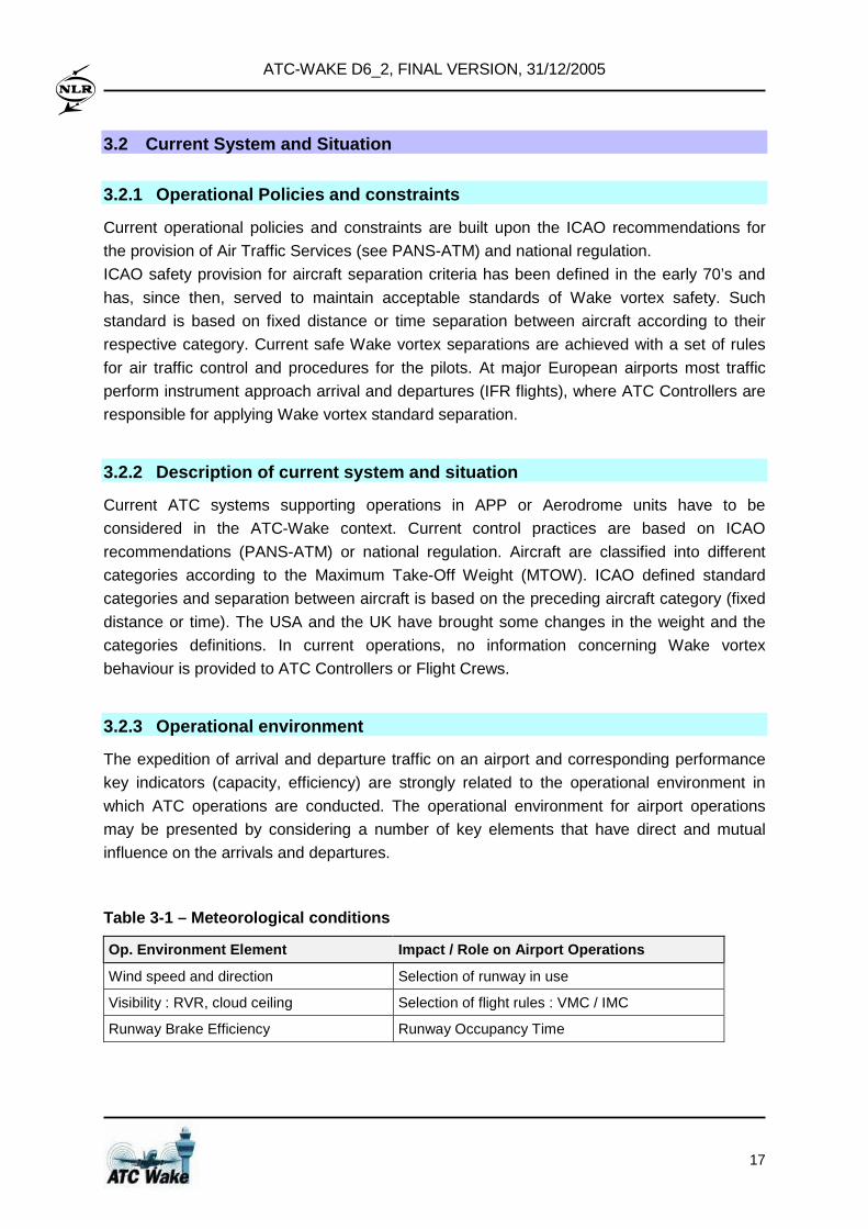
List of Tables
Table 3-1 – Meteorological conditions ..................................................................................17 Table 3-2 – Airport layout and infrastructure.........................................................................18 Table 3-3 – Ground and aircraft equipment ..........................................................................18 Table 3-4 – ATC organisation...............................................................................................18 Table 3-5 – ATC-Wake Users or Involved Actors .................................................................24 Table 3-6 – Automated systems as actors for ATC-Wake ....................................................25 Table 3-7 – Runway configurations and modes of operations considered ............................29 Table 3-8 – Meteorological conditions for ATC-Wake operations .........................................35 Table 3-9 – Separation Mode depending on atmospheric conditions....................................35 Table 3-10 –Ground and aircraft equipment for ATC-Wake operations ................................36 Table 3-11 – Airport layout and infrastructure for ATC-Wake operations ..............................36 Table 3-12 – ATC-Wake Separation Mode Planner Functionality .........................................36 Table 3-13 – ATC-Wake Predictor Functionality...................................................................37 Table 3-14 – ATC-Wake Detector Functionality....................................................................37 Table 5-1 – Risk requirements (per queued aircraft movement) ...........................................69 Table 5-2 – ESARR 4 severity classification scheme in ATM ...............................................70 Table 5-3 – Frequency categories used in this study............................................................72 Table 5-4 – Risk tolerability matrix for accident and incidents...............................................73 Table 5-5 – Effect of main ATC-Wake DWA conditions ........................................................76 Table 5-6 – Overview of potential SAFETY BOTTLENECKS for the conflict scenarios................78 Table 5-7 – Aircraft types for single runway arrivals .............................................................84 Table 5-8 – Indicative separation per crosswind interval for single runway arrivals...............86 Table 5-9 – Assessment parameters for the SRD operation.................................................86 Table 5-10 – Aircraft characteristics (derived from Eurocontrol BADA, Revision 3.6) ...........87 Table 5-11 – Estimated lift off points of different aircraft types (at Schiphol runway 24)........88 Table 5-12 – Indicative separation per crosswind interval for the SRD operation..................89 Table 5-13 – Assessment parameters for the CSPRA operation ..........................................90 Table 5-14 – Indicative separation per crosswind interval for the CSPRA operation.............92 Table 5-15 – Indicative separation per crosswind interval for the ATC-Wake operation........93 Table 5-16 – Departure throughput in case of ICAO or reduced separation (from D4_5)......93 Table 5-17 – Arrival throughput in case of ICAO or reduced separation (from D4_5) ...........94 Table 5-18 – Arrival delay in case of ICAO or reduced separation (from D4_5)....................94 Table 5-19 – Expected throughput for the SRA operation.....................................................94 Table 5-20 – Expected delay for the SRA operation .............................................................95 Table 5-21 – Expected throughput for the SRD operation ....................................................95 Table 5-22 – Summary of runway throughput and delay characteristics ...............................96 Table 6-1 – Results from ATC-Wake System Usability Questionnaires ..............................103 Table 7-1 – Overview implementation effort per system .....................................................116 Table 7-2 – Overview costs per system..............................................................................117
ATC-WAKE D6_2, FINAL VERSION, 31/12/2005
XIV
ATC-WAKE D6_2, FINAL VERSION, 31/12/2005
1
1 Introduction
1.1 Scope
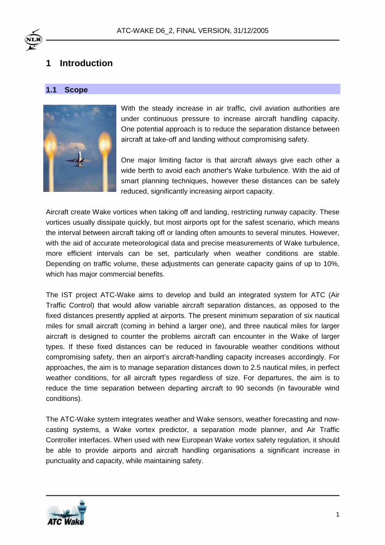
With the steady increase in air traffic, civil aviation authorities are
under continuous pressure to increase aircraft handling capacity.
One potential approach is to reduce the separation distance between
aircraft at take-off and landing without compromising safety.
One major limiting factor is that aircraft always give each other a
wide berth to avoid each another's Wake turbulence. With the aid of
smart planning techniques, however these distances can be safely
reduced, significantly increasing airport capacity.
Aircraft create Wake vortices when taking off and landing, restricting runway capacity. These
vortices usually dissipate quickly, but most airports opt for the safest scenario, which means
the interval between aircraft taking off or landing often amounts to several minutes. However,
with the aid of accurate meteorological data and precise measurements of Wake turbulence,
more efficient intervals can be set, particularly when weather conditions are stable.
Depending on traffic volume, these adjustments can generate capacity gains of up to 10%,
which has major commercial benefits.
The IST project ATC-Wake aims to develop and build an integrated system for ATC (Air
Traffic Control) that would allow variable aircraft separation distances, as opposed to the
fixed distances presently applied at airports. The present minimum separation of six nautical
miles for small aircraft (coming in behind a larger one), and three nautical miles for larger
aircraft is designed to counter the problems aircraft can encounter in the Wake of larger
types. If these fixed distances can be reduced in favourable weather conditions without
compromising safety, then an airport’s aircraft-handling capacity increases accordingly. For
approaches, the aim is to manage separation distances down to 2.5 nautical miles, in perfect
weather conditions, for all aircraft types regardless of size. For departures, the aim is to
reduce the time separation between departing aircraft to 90 seconds (in favourable wind
conditions).
The ATC-Wake system integrates weather and Wake sensors, weather forecasting and now-
casting systems, a Wake vortex predictor, a separation mode planner, and Air Traffic
Controller interfaces. When used with new European Wake vortex safety regulation, it should
be able to provide airports and aircraft handling organisations a significant increase in
punctuality and capacity, while maintaining safety.
ATC-WAKE D6_2, FINAL VERSION, 31/12/2005
2
The ATC-Wake decision-support system and procedures will help air traffic controllers
decide how long the intervals should be. These procedures are based on laser technology
called Lidar, which monitors the movement of dust particles through the air. This system is
used to continually monitor Wake turbulence on runways. Wake turbulence data is combined
with meteorological data to generate recommendations for intervals, which are displayed on
the air traffic controller's screen. These recommendations are also used in planning systems
at air traffic management.
1.2 Objectives
The main objective of ATC-Wake is to develop and build an integrated ATC Wake Vortex
Safety and Capacity platform. A variety of existing subsystems is integrated such that this
platform is used within a test bed environment role:
• To evaluate the interoperability of the ATC-Wake system with existing ATC systems
currently used at various European airports;
• To assess the safety and capacity improvements that can be obtained by local
installation of the ATC-Wake system at various European airports;
• To evaluate operational usability and acceptability of the ATC-Wake system;
• To make a plan and to assess the costs for further implementation and exploitation of the
ATC-Wake IP platform into the system that can be installed at European airports).
This platform is an essential step that will lead to installation of an integrated ATC decision
support system at airports, enabling air traffic controllers to apply new optimised weather
based aircraft spacing. The ATC system will integrate weather and Wake sensors, weather
forecasting and now-casting systems, Wake vortex prediction system, separation mode
planner, and air traffic controller interface. Used with new harmonised safety regulation, this
system will provide tactical and strategic benefits, while maintaining safety. The project will
focus on the following aspects:
1. Runway configurations: Single runways, closely spaced parallel runways.
2. Aircraft operations: Landing, take-off, and mixed mode operations.
3. Weather conditions: Wind condtions favourable for reduced aircraft separation.
A further aim is to analyse both tactical and strategic benefits of using this integrated system
at various European airports. Tactical benefits in terms of temporary capacity increases, to
improve the management of arrival flows while reducing holding. Strategic benefits in terms
of long-term runway capacity for airline schedule planning.
The proposed time frame for local installation of the integrated system at European airports
is 2010, which implies that the baseline – with the exception of the Wake vortex systems
evolving from this project – is today’s airport environment with current infrastructure systems.
The integrated platform will be extendable, such that evaluation of future systems and
concepts will be feasible after completion of ATC-Wake.
ATC-WAKE D6_2, FINAL VERSION, 31/12/2005
3
The impact of weather on Wake vortex safety is a crucial aspect, and the uncertainty in
predicting the behaviour of Wake vortices in different weather conditions implies that
continuous monitoring of both Wake vortices and weather will be necessary. This will enable
continuous verification – and possibly update – of safe predictions of required aircraft
separation minima. The ATC Wake system will therefore integrate:
• Weather and Wake Sensors;
• Weather Forecasting and Nowcasting Systems;
• Wake Vortex Prediction Systems;
• Aircraft Separation (Mode) Planner;
• Air Traffic Controller Human Machine Interfaces (HMIs).
Integration of the heterogeneous subsystems (provided by different partners) requires state-
of-the-art middleware facilities, including a variety of methods for integration (e.g.,
static/dynamic interaction, tool chaining, workflow chains). Design of the integrated platform
comprises the design of system architecture, interfaces, common database, scenario
manager, and human-machine interfaces (including air traffic controller HMIs, and Wake and
weather monitoring interfaces).
Emphasis is placed on validation and calibration aspects for the integrated platform and the
subsystems. ATS providers (as end-users), an aircraft manufacturer, and regulatory
authorities (responsible for safety) have been consulted regularly throughout the project to
support exploitation of the platform.
The local installation of the integrated system at European airports will require new safety
regulation, since the present Wake vortex safety recommendations and best practices do not
take new modified ATC systems into account. Specific attention has been given to the issue
of development of new Wake vortex safety regulation. To enhance acceptability of the
integrated system (and other new technologies, including high capacity aircraft and on-board
Wake detection and warning instrumentation), the project has built on discussions with the
FAA/EUROCONTROL Action Plan 14 on Wake Vortex and the Thematic Networks
WakeNet2 Europe and WakeNet USA.
1.3 Description of work
The main work has been to develop and build an integrated ATC Wake vortex safety and
capacity platform. The work is based on six work packages:
• WP1: System Requirements
The main work is to define the requirements for the system. This includes the operational
requirements, the operational concept and procedures, the users requirements, and the
system requirements.
ATC-WAKE D6_2, FINAL VERSION, 31/12/2005
4
• WP2: Integrated System Design and Evaluation
The main work is to develop and build the platform, integrating all subsystems. This
includes a Wake vortex prediction and monitoring system, weather forecasting and
monitoring systems, aircraft spacing predictor, and human machine interface for air traffic
controllers. A task is to evaluate technical feasibility of building the system.
• WP3: Safety and Capacity Analysis
The main work is to quantify and evaluate possible safety and capacity improvements
(tactical and strategic benefits) when using the system. Safe and appropriate separation
distances will be determined for single runways (arrivals and departures) and closely
spaced parallel runway arrivals.
• WP4: Evaluation of Operational Feasibility
The main work is to evaluate operational feasibility of the system, including analysing the
interoperability with existing ATC systems, and the usability and acceptability by air traffic
controllers.
• WP5: Technological Implementation Plan (TIP)
The main work is to provide the TIP, in accordance with the guidelines from the EC. This
will be done in co-ordination with the User Group members, and representatives of the
aerospace and ATM community
• WP6: Management and Final Synthesis
The main work is to maintain an efficient communication with the EC, other related
projects, and to disseminate findings through workshops, conferences, and an Internet
Site. A further task is the final synthesis, resulting in a publishable final report with
conclusions and recommendations.
1.4 Contribution to EC IST Programme
The work contributes directly to several objectives of the EC Information Society
Technologies (IST) Programme for creating a User Friendly Information Society. For Key
Action I – Systems and services for the Citizen, the project addresses objective I.5 Transport
and Tourism by developing and building an integrated ATC Wake vortex safety and capacity
platform with the aim to improve safety. This allows more efficient and comfortable transport,
resulting in airport capacity increase. Research is focused on sub-task I.5.2 Integrated
vehicle infrastructure systems which aims to improve safety, security, comfort and efficiency
in all modes of passenger and freight transport and to improve mobility management,
through more interaction between in-vehicle systems and infrastructure systems (transport,
navigation, communication, etc.).
ATC-WAKE D6_2, FINAL VERSION, 31/12/2005
5
The ATC Wake vortex safety and capacity platform contains:
• Weather and Wake sensors (including coverage):
• Ground based: C band weather radar, Wake detection / wind LIDAR;
• Aircraft based: Wake detection / wind LIDAR;
• Wind / temperature profilers and radiosondes.
• Weather forecasting and nowcasting systems;
• Wake vortex prediction systems;
• Aircraft Separation Mode Planner;
• Air Traffic Controller Human Machine Interface (HMI).
The ICT based application platform will integrate various infrastructures with advanced co-
operation of aircraft and ground-based systems and processes. Navigation and surveillance
systems, communication between controllers and pilots, observation and monitoring of
weather and Wake vortex behaviour are all required to be taken into account in order to
provide controllers with reliable and realistic decision support with respect to aircraft spacing.
Interoperability, inter-working, openness and integration of subsystems will be achieved
through the use of a middleware system that provides an integrated view on a
heterogeneous network of different computer platforms enabling access to different
subsystems. The operational usability and acceptability of the integrated system will be given
particular emphasis, through realisation of an advanced controller HMI, which will be tested
by different controller teams. This will be supported by simulations proving that risk
requirements and capacity aims can be realised.
The main expected exploitable project output is the integrated ATC Wake vortex safety and
capacity platform, which contains as further exploitable elements:
• ATC-Wake Separation Mode Planner;
• ATC-Wake Predictors;
• ATC-Wake Monitoring and Alerting;
• ATC-Wake Detectors;
• Air Traffic Controller Human Machine Interface (HMI).
All the project outputs will be directly exploitable (i.e., short-term timing), to support the
design of new airports (with additional (closely spaced) parallel runways) and to support the
assessment of safety and capacity impacts to aircraft flying within the vicinity of the new
Airbus A380. Timing for local installation of the integrated system at European airports will be
medium/long term, since this will depend on follow-up actions by industry and on new
harmonised Wake vortex safety regulation, building on recommendations evolving from ATC-
Wake project.
ATC-WAKE D6_2, FINAL VERSION, 31/12/2005
6
1.5 Overview of project actual outcome
The ATC-Wake platform enables European ATS providers, airport authorities, and ATM
research and development centres to join their efforts (and plan their investments) to
adequately adapt their airport systems and enhance the efficient use of airports restricted by
the Wake vortex problem. In this sense ATC-Wake is a key enabler of the European ATM
strategy for the years 2000+. Wake Vortex is included in the Single European Sky ATM
Masterplan activities (joint Eurocontrol/EC SESAME project). ATC-Wake is also included in
the Eurocontrol Wake Vortex Separations Management Plan. The main project results are:
• ATC-Wake Integrated Platform (with interfaces between existing subsystems and tools
and new ATC-Wake components; implemented using SPINEware);
• Connection with an on-board Wake detection, warning, and avoidance system for Wake
vortex and other atmospheric hazards;
• ATC-Wake Separation Mode Planner;
• ATC-Wake Predictors;
• ATC-Wake Monitoring and Alerts;
• ATC-Wake Detectors;
• Probabilistic simulation tool for assessment of Wake vortex safety of new ATM
operational concepts and procedures for Wake vortex avoidance;
• Wake vortex safety assessment results (arrivals and departures);
• Proposed new Wake vortex safety regulation;
• Fast-time simulation tool for the assessment of capacity related to new ATM operational
concepts and procedures for Wake vortex avoidance;
• Capacity assessment results (for a generic airport);
• ATC-Wake Human Machine Interfaces for controllers (and the associated ATC real time
simulation software);
• Operational requirements, operational concepts, user requirements, working methods for
air traffic controllers and the ATC supervisors.
Existing subsystems and tools (weather and Wake sensors, weather forecasting and
nowcasting systems, Wake vortex prediction systems, Wake vortex safety assessment tools
and capacity assessment tools) have been upgraded following definition of the ATC-Wake
system requirements, operational concept, and working methods.
1.6 Document structure
Section 2 provides an overview/state-of-the-art describing the innovative aspects of this
project. The ATC-Wake operational concept and system requirements are described in
Section 3. The ATC-Wake system design and development is contained in Section 4,
together with a detailed description of the Integrated Platform, including the four new
components: Separation Mode Planner, Predictor, Detector, and Monitoring and Alerting.
ATC-WAKE D6_2, FINAL VERSION, 31/12/2005
7
Section 5 describes the safety and capacity improvements that can be obtained by local
installation of the ATC-Wake system at European airports. The results from technical and
operational feasibility analysis are described in Sections 6, together with a plan for
exploitation of the project results by end-users. Section 7 provides the conclusions and
recommendations. The appendices give some further details on the work performed.
ATC-WAKE D6_2, FINAL VERSION, 31/12/2005
8
2 Overview / state-of-the-art / innovation
2.1 Wake Vortex Phenomena and Implications for Airp ort Operations
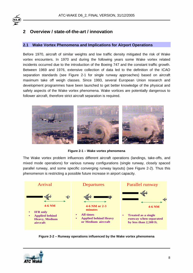
Before 1970, aircraft of similar weights and low traffic density mitigated the risk of Wake
vortex encounters. In 1970 and during the following years some Wake vortex related
incidents occurred due to the introduction of the Boeing 747 and the constant traffic growth.
Between 1969 and 1976, extensive collection of data led to the definition of the ICAO
separation standards (see Figure 2-1 for single runway approaches) based on aircraft
maximum take off weigh classes. Since 1993, several European Union research and
development programmes have been launched to get better knowledge of the physical and
safety aspects of the Wake vortex phenomena. Wake vortices are potentially dangerous to
follower aircraft, therefore strict aircraft separation is required.
Figure 2-1 – Wake vortex phenomena
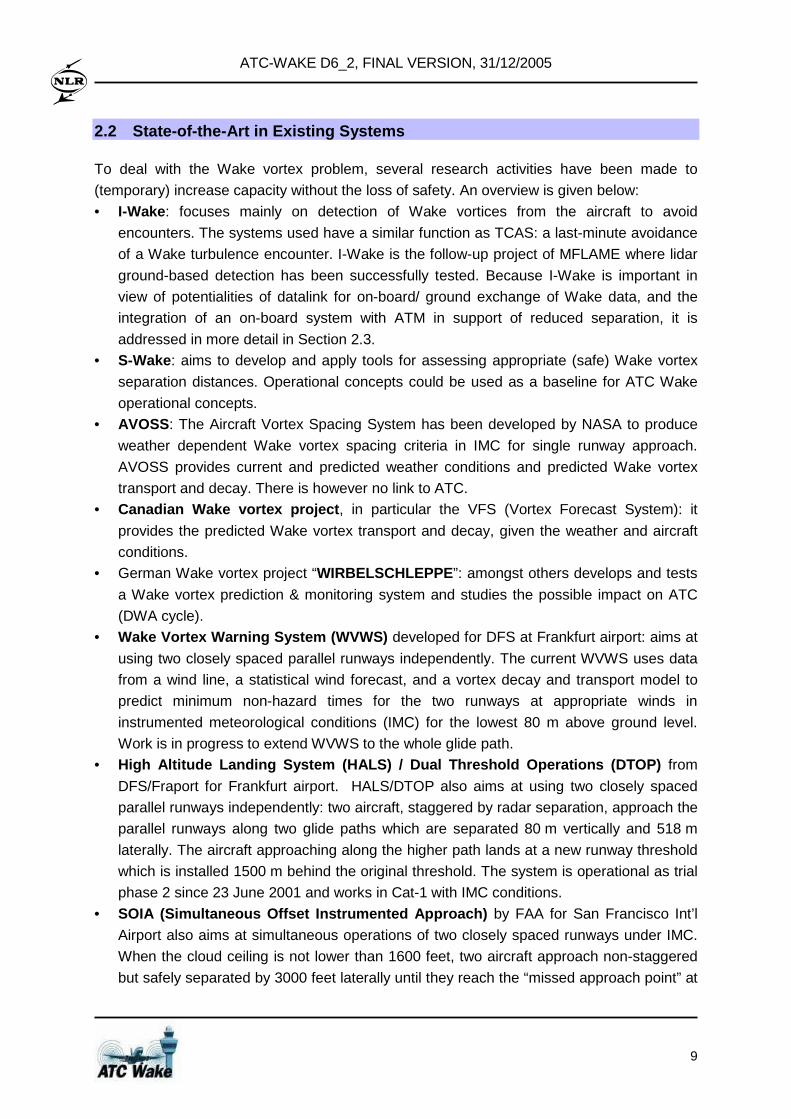
The Wake vortex problem influences different aircraft operations (landings, take-offs, and
mixed mode operations) for various runway configurations (single runway, closely spaced
parallel runway, and some specific converging runway layouts) (see Figure 2-2). Thus this
phenomenon is restricting a possible future increase in airport capacity.
Arrival Departures
4-6 NM or 2-3 minutes
• All times • Applied behind Heavy
or Medium aircraft
Parallel runway
4-6 NM
• Treated as a single runway when separated by less than 2,500 ft.
• IFR only • Applied behind
Heavy, Medium aircraft
4-6 NM
Figure 2-2 – Runway operations influenced by the Wa ke vortex phenomena
ATC-WAKE D6_2, FINAL VERSION, 31/12/2005
9
2.2 State-of-the-Art in Existing Systems
To deal with the Wake vortex problem, several research activities have been made to
(temporary) increase capacity without the loss of safety. An overview is given below:
• I-Wake: focuses mainly on detection of Wake vortices from the aircraft to avoid
encounters. The systems used have a similar function as TCAS: a last-minute avoidance
of a Wake turbulence encounter. I-Wake is the follow-up project of MFLAME where lidar
ground-based detection has been successfully tested. Because I-Wake is important in
view of potentialities of datalink for on-board/ ground exchange of Wake data, and the
integration of an on-board system with ATM in support of reduced separation, it is
addressed in more detail in Section 2.3. • S-Wake: aims to develop and apply tools for assessing appropriate (safe) Wake vortex
separation distances. Operational concepts could be used as a baseline for ATC Wake
operational concepts. • AVOSS: The Aircraft Vortex Spacing System has been developed by NASA to produce
weather dependent Wake vortex spacing criteria in IMC for single runway approach.
AVOSS provides current and predicted weather conditions and predicted Wake vortex
transport and decay. There is however no link to ATC. • Canadian Wake vortex project , in particular the VFS (Vortex Forecast System): it
provides the predicted Wake vortex transport and decay, given the weather and aircraft
conditions. • German Wake vortex project “WIRBELSCHLEPPE ”: amongst others develops and tests
a Wake vortex prediction & monitoring system and studies the possible impact on ATC
(DWA cycle). • Wake Vortex Warning System (WVWS) developed for DFS at Frankfurt airport: aims at
using two closely spaced parallel runways independently. The current WVWS uses data
from a wind line, a statistical wind forecast, and a vortex decay and transport model to
predict minimum non-hazard times for the two runways at appropriate winds in
instrumented meteorological conditions (IMC) for the lowest 80 m above ground level.
Work is in progress to extend WVWS to the whole glide path. • High Altitude Landing System (HALS) / Dual Threshol d Operations (DTOP) from
DFS/Fraport for Frankfurt airport. HALS/DTOP also aims at using two closely spaced
parallel runways independently: two aircraft, staggered by radar separation, approach the
parallel runways along two glide paths which are separated 80 m vertically and 518 m
laterally. The aircraft approaching along the higher path lands at a new runway threshold
which is installed 1500 m behind the original threshold. The system is operational as trial
phase 2 since 23 June 2001 and works in Cat-1 with IMC conditions.
• SOIA (Simultaneous Offset Instrumented Approach) by FAA for San Francisco Int’l
Airport also aims at simultaneous operations of two closely spaced runways under IMC.
When the cloud ceiling is not lower than 1600 feet, two aircraft approach non-staggered
but safely separated by 3000 feet laterally until they reach the “missed approach point” at
ATC-WAKE D6_2, FINAL VERSION, 31/12/2005
10
about 1000 feet height and 3.3 nautical miles before the threshold. The final approach is
then flown under VMC (S-shape flight pattern). • SYAGE developed in France for Toulouse-Blagnac airport): The SYsteme Anticipatif de
Gestion des Espacements aims at reduced separations for single runway departures;
uses ground-based wind measurements and Wake vortex model VORTEX.
Time Based Separation : developed by EUROCONTROL for investigation of the possibilities
of preventing loss of runway capacity against strong headwind conditions while maintaining the
required level of safety. Today, distance based separation criteria are generally used at major
airports. However, they are used in all weather conditions and do not take into account the
impact of the wind on the aircraft speed. Under strong headwind conditions, aircraft need
significant more time to fly the same distance. When applying distance based separations, this
could result in a loss of capacity. If the standard separation were replaced by time-based
interval, this could avoid losing the airport capacity under certain weather conditions.
A summary of Wake-vortex issues with a view of research and air-transportation industry can
be found in the “Position Papers” elaborated within the Thematic Network WakeNet2 Europe
and the associated dissemination and presentation material.
The above systems and associated procedures enhancing a (temporary) reduction of
separation were all developed for specific airports (such as Frankfurt). Up to now, of these
systems only HALS / DTOP is operational. An innovative aspect of the present ATC-Wake
project is to enhance the development of ONE integrated system that can handle VARIOUS
runway configurations (closely spaced parallel runways, single runways). An integrated ATC-
Wake platform is an essential intermediate step towards realisation and installation of a
future ATC-Wake system at European airports.
2.3 On-board Wake detection
Wake vortex remote detection with onboard sensors focused primarily on the potential use of
LiDAR in 1993 with the EC funded FLAME project, leading to successful ground tests in
2000 during MFLAME and the world premiere flight tests in I-Wake in 2004. The know-how
gained with these projects concerns the available technology through:
• the manufacturing of lightweight mirror-based scanner,
• the building and integrating of a LiDAR demonstrator,
• its ruggedisation to go from laboratory to shelter to finally aircraft installation
• its integration with aircraft systems (Air Data and Inertial System).
MFLAME allowed to develop signal processing techniques that revealed efficient in detecting
Wake vortices from the ground down to the level of Fokker 100 Wakes. I-Wake took the
ATC-WAKE D6_2, FINAL VERSION, 31/12/2005
11
challenge further to adapt the signal processing algorithms to a moving platform with an
'almost' forward looking sensor geometry, a platform flying at higher altitudes thus yielding
poorer signal to noise ratios and range-dependent noise spectra. In parallel to the flight tests,
flight simulator tests allowed to propose to pilots Human Machine Interface (HMI) concepts
for the Navigation Display (ND), the Primary Flight Display (PFD) and the Vertical Situation
Display (VSD). Strategic and tactical information on Wake vortex 3D position, including
tactical alerts (caution and warning) with estimated time to encounter were reviewed until
accepted by pilots.
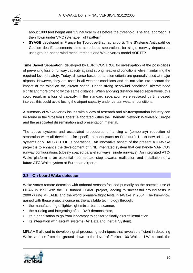
The technology part of I-Wake had the objectives (1) to promote the IR laser for atmospheric
hazard detection as a first brick to a European LiDAR system and (2) to develop and assess
automatic pattern recognition techniques. At the end of the project, a laboratory mock-up of
2µm laser was tested with satisfactory performances and pattern recognition techniques
showed encouraging results on the ground based MFLAME data. As a background task
started in MFLAME, I-Wake contributed to the system definition in terms of a end-user
requirements, functional architecture with selected sensors and detection methods, use of
Wake vortex model in support of LiDAR including datalink requirements, potentialities of
datalink for ground/board exchange of Wake data, integration of onboard system with ATM in
support of reduced separation distances (including result sharing with ATC-Wake). The
overall system is functionally represented in Figure 2-3.
W e t a tm o s p h e reC o n v e c tiv e a c tiv ity
D ry a tm o s p h e re
C ru is e
A p p ro a c h
T a k e -o ff& L a n d in g
R a d a r D e te c tio n *
P re d ic tio nw a k e
D e te c tio n ra n g e fo r a p p ro p r ia te a d v a n c e w a rn in g
L iD A R d e te c tio n
Functions in all phases of flight
F u n c tio n s in a ll w e a th e r + m u lti-h a z a rd c a p a b ility
W e t a tm o s p h e reC o n v e c tiv e a c tiv ity
D ry a tm o s p h e re
C ru is e
A p p ro a c h
T a k e -o ff& L a n d in g
R a d a r D e te c tio n *
P re d ic tio nw a k e
D e te c tio n ra n g e fo r a p p ro p r ia te a d v a n c e w a rn in gD e te c tio n ra n g e fo r a p p ro p r ia te a d v a n c e w a rn in g
L iD A R d e te c tio n
Functions in all phases of flight
Functions in all phases of flight
F u n c tio n s in a ll w e a th e r + m u lti-h a z a rd c a p a b ilityF u n c tio n s in a ll w e a th e r + m u lti-h a z a rd c a p a b ility
Figure 2-3 – Atmospheric Hazard Detection, Warning and Avoidance (DWA) System
2.4 Weather Nowcasting and Wake Vortex Prediction
Several of the required components of the ATC-Wake system have already been partially
combined and tested in an actual airport environment during two weather and Wake
measurement campaigns. Weather now-casting, weather monitoring by a Doppler C-band
ATC-WAKE D6_2, FINAL VERSION, 31/12/2005
12
radar (in both mono-static and bi-static modes), a wind/temperature profiler, radiosondes,
wind LiDAR; Wake predictors (P-VFS, P2P), Wake detectors and characterisers by wind and
Wake LiDARs have been used together in an airport Wake Vortex Prediction and Monitoring
environment during the measurement campaign WakeOP (in Oberpfaffenhofen) and
WakeToul (in Toulouse). The full combination and automation of (emulators of) all
components with new ATC-Wake components, as part of the ATC-Wake Integrated Platform,
is an essential innovative step showing the technical feasibility of building the ATC-Wake
system and enabling access of ATC providers to Wake Vortex information.
One of the real-time Wake vortex predictors is the Vortex Forecast System (VFS), an
operational Wake vortex predictor, developed under contract with Transport Canada (TC)
and its Transportation Development Center (TDC) during 6 Phases (1993 to 2000), by an
international team, including Russian, Belgian, and Canadian collaboration. The
development and validation was done in further close collaboration with the Aircraft VOrtex
Spacing System (AVOSS) program (NASA LaRC). Some specific VFS capabilities were
identified and recognised as preferable to other predictors: modelling of ground effects and of
non-uniform wind shear effects. The VFS is run in multiple gates along the flight track and
handles modelling of:
1. the initial near Wake using the Near Wake DataBase (NWDB), or using the Universal
Near Wake (UNW) shortly after rollup;
2. Wake transport, using the Wake-induced velocities and the wind velocity profile;
3. Wake slow decay, using the atmospheric turbulence profile (EDR or TKE decay models),
and Wake abrupt decay, with critical time function of EDR;
4. ground effects, using injection of secondary vortices from the ground;
5. non-uniform wind shear effects, using additional velocities applied to the vortices;
6. stratification effects, using the atmospheric stratification profile.
2.5 Weather and Wake Monitoring
A building block necessary to build sufficient confidence in the model predictions for Wake
vortices evolution in relation to weather will be to use data from a C-Band Doppler weather
radar for weather monitoring but also Wake-vortex monitoring. Several US references in
scientific literature put forward the idea that a Doppler radar can detect Wake vortices, and
the ATC-Wake project is the first to explore the use of C-band Doppler radar data in the
context of Wake vortex prediction and monitoring. The interest of radar for weather analysis
is its complementarity to the lidar system:
• it can provide additional meteorological parameters besides performing turbulence
detection (especially for mapping of precipitations areas where lidar is not efficient : this
information could be used in fusion process to choose the best sensor);
• the potential detection range on Wake vortex is at least the same as for lidar in clear air,
but is larger in humid air and in rain.
ATC-WAKE D6_2, FINAL VERSION, 31/12/2005
13
Principles and algorithms (for atmospheric turbulence detection and weather forecasting)
previously developed within three European studies of the 4th RTD Framework Programme:
4DMIDaBLE for DG7, DOLPHINS for DG12, and PRESTO for DG13 will be used. These
algorithms improve significantly the Doppler radar analysis performances and are well
adapted for Wake-Vortex monitoring. Some principles have already been validated on low
altitude wind-shears detection. A new algorithm for rain cloud tracking and wind field
estimation for Weather forecasting will be established. The aim of this algorithm is to perform
short term forecasting of dynamic radar clutter evolution.
2.6 Wake Vortex Safety and Capacity Analysis
One of the innovative building blocks for the ATC-Wake system will be the Separation Mode
Planner, a tool that will provide the required separation distances between aircraft under
different operational and weather and wind conditions. This tool will be established on the
basis of one of the main exploitable outputs from the S-Wake project: a probabilistic Wake
vortex induced risk assessment methodology and tool-set. WAVIR has been applied in S-
Wake to evaluate single runway approaches, but will be extended – in ATC-Wake – to cover
the whole airport environment, with different aircraft operations (landings and take-offs) to
various runway configurations. It should be noted that the risk assessment methodology from
S-Wake is based on an assessment of incident/accident risk probabilities, in accordance with
common safety regulation in other industries.
Safe and appropriate aircraft spacing distances are determined through a comparison with
risk requirements (e.g. Target Level of Safety values), which can be set by regulatory
authorities. Usually these risk requirements are determined on the basis of historical
incident/accident data, gathered through incident reporting activities such as being
undertaken in the United Kingdom. Two members of the ATC-Wake User Group are highly
experienced with the assessment of safety requirements and the validation of the safety
assessment. This will limit the risk of non-acceptance of the safety assessment results wake
vortex safety regulation, and will stimulate that the Separation Mode Planner results are in
line with wake vortex safety requirements.
Possible capacity improvements (tactical and strategic) after installation of the integrated
system at European airports will be analysed using a series of tools and simulation platforms
developed and used by EUROCONTROL for providing performance predictions for the future
ATM system.
ATC-WAKE D6_2, FINAL VERSION, 31/12/2005
14
2.7 ATC Wake Vortex Decision Support Facilities
One further innovative output of ATC-Wake will be the controller Human Machine Interfaces
(HMI), which will be developed and optimised for tower and Terminal Area (TMA) / en-route
controllers, under the commitment to the principles of human centred automation. That
means, with priority to providing optimal decision support to the controllers, who will keep the
ultimate responsibility for their decisions, HMIs will have to reflect a synthesis between:
• specific controller needs for information and decision support;
• usability and acceptability of the HMIs;
• airport operational requirements and constraints (e.g. runway availability);
• traffic demands (e.g. amount of inbound/outbound traffic); and
• technical functionality provided by the integrated system, particularly for Wake vortex
prediction and monitoring, and aircraft spacing prediction.
A further issue is merging those functionalities with other functions at the controller working
positions (e.g. approach planning, departure planning). This issue will be addressed through
an analysis of the interoperability with existing ATC systems and the usability and
acceptability of the system.
2.8 Integrated Platform and ICT Infrastructure
The ATC-Wake integrated platform will establish and facilitate the collaboration between the
partners and their subsystems. This collaboration will be conducted in a heterogeneous,
multi-disciplinary and distributed network, for the subsystems have very distinct
characteristics and are located at different companies. Typically, the subsystems require
different hardware and operating systems, range from real-time and fast-time simulators to
analysis tools, reflect different disciplines, and operate in different companies' computer
networks.
To establish collaboration in heterogeneous and distributed networks, state-of-the-art ICT
technology is applied to set up the required communication infrastructure and to provide user
support. The resulting integrated platform will be presented to users (including ATS
providers, airport authorities, ATM industry, and ATM research and development centres) as
a user-centred working environment. This platform will give easy access to the subsystems
in the network and takes care of an efficient use of them. Moreover, the platform is presented
to the user as a single, virtual machine, providing him a transparent view of the network,
improving interactions with the subsystems, and enabling an efficient and effective use of the
platform. The platform will also enable quality control and cost reduction, because it allows
for an efficient exchange, conservation, and maintenance of documents, subsystems, and
expertise. Further, its modularity will allow for easy extension of the platform by new,
alternative, or enhanced subsystems in the future, and the setting-up of new collaborations
ATC-WAKE D6_2, FINAL VERSION, 31/12/2005
15
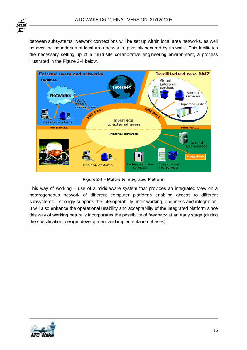
between subsystems. Network connections will be set up within local area networks, as well
as over the boundaries of local area networks, possibly secured by firewalls. This facilitates
the necessary setting up of a multi-site collaborative engineering environment, a process
illustrated in the Figure 2-4 below.
Figure 2-4 – Multi-site Integrated Platform
This way of working – use of a middleware system that provides an integrated view on a
heterogeneous network of different computer platforms enabling access to different
subsystems – strongly supports the interoperability, inter-working, openness and integration.
It will also enhance the operational usability and acceptability of the integrated platform since
this way of working naturally incorporates the possibility of feedback at an early stage (during
the specification, design, development and implementation phases).
ATC-WAKE D6_2, FINAL VERSION, 31/12/2005
16
3 Operational Concept and System Requirements
3.1 Objectives
The main objective of WP1 was to define the requirements for the integrated ATC system.
This included the definition of operational concepts and procedures in support of the
development and actual use of the integrated system. At present, in low visibility conditions,
the currently applied Wake vortex constraints are not weather dependent and the separation
between aircraft is therefore based on a worst-case scenario. The spacing is determined by
considering the leader/follower aircraft weight categories and Wake persistence observed
during atmospheric conditions favourable to long vortex life. These separations are
conservative; they do not completely avoid the effect of Wake vortices, but they are sufficient
to be safe in most meteorological conditions.
Several technologies to detect and predict Wake-vortex have been developed during the last
years. These technologies are now quite mature and weather conditions in which Wake
vortices decay quickly can be identified and used reliably as "Wake vortex predictors"; there
is potential for making the separation distances dependent on these predictors as well as
aircraft weight. This could increase the capacity of airports in certain weather conditions.
Nevertheless, today, there is no link to ATC and subsequently no system integrating all the
sources of information together at a single source, accessible by all ATC providers (en-route,
approach, tower and arrival/ departure managers). Hence, the derivation of the system
requirements is:
• To define operational requirements;
• To define operational concepts and procedures, to update and refine the selected
operational concepts and procedures;
• To define users requirements;
• To define the system requirement based on operational concepts and users
requirements.
To meet the objectives, the following issues were addressed:
• Operational issues: need and use of WV information in the context of ATC operations,
constraints and required support systems
• Technical issues: high level interface to existing (legacy) ATC systems of WV targeted
system.
ATC-WAKE D6_2, FINAL VERSION, 31/12/2005
17
3.2 Current System and Situation
3.2.1 Operational Policies and constraints
Current operational policies and constraints are built upon the ICAO recommendations for
the provision of Air Traffic Services (see PANS-ATM) and national regulation.
ICAO safety provision for aircraft separation criteria has been defined in the early 70’s and
has, since then, served to maintain acceptable standards of Wake vortex safety. Such
standard is based on fixed distance or time separation between aircraft according to their
respective category. Current safe Wake vortex separations are achieved with a set of rules
for air traffic control and procedures for the pilots. At major European airports most traffic
perform instrument approach arrival and departures (IFR flights), where ATC Controllers are
responsible for applying Wake vortex standard separation.
3.2.2 Description of current system and situation
Current ATC systems supporting operations in APP or Aerodrome units have to be
considered in the ATC-Wake context. Current control practices are based on ICAO
recommendations (PANS-ATM) or national regulation. Aircraft are classified into different
categories according to the Maximum Take-Off Weight (MTOW). ICAO defined standard
categories and separation between aircraft is based on the preceding aircraft category (fixed
distance or time). The USA and the UK have brought some changes in the weight and the
categories definitions. In current operations, no information concerning Wake vortex
behaviour is provided to ATC Controllers or Flight Crews.
3.2.3 Operational environment
The expedition of arrival and departure traffic on an airport and corresponding performance
key indicators (capacity, efficiency) are strongly related to the operational environment in
which ATC operations are conducted. The operational environment for airport operations
may be presented by considering a number of key elements that have direct and mutual
influence on the arrivals and departures.
Table 3-1 – Meteorological conditions
Op. Environment Element Impact / Role on Airport Operations
Wind speed and direction Selection of runway in use
Visibility : RVR, cloud ceiling Selection of flight rules : VMC / IMC
Runway Brake Efficiency Runway Occupancy Time
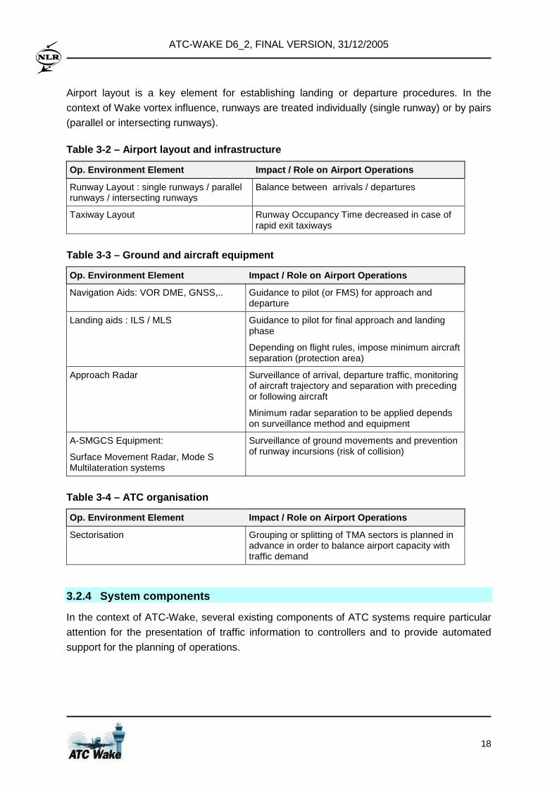
ATC-WAKE D6_2, FINAL VERSION, 31/12/2005
18
Airport layout is a key element for establishing landing or departure procedures. In the
context of Wake vortex influence, runways are treated individually (single runway) or by pairs
(parallel or intersecting runways).
Table 3-2 – Airport layout and infrastructure
Op. Environment Element Impact / Role on Airport Operations
Runway Layout : single runways / parallel runways / intersecting runways
Balance between arrivals / departures
Taxiway Layout Runway Occupancy Time decreased in case of rapid exit taxiways
Table 3-3 – Ground and aircraft equipment
Op. Environment Element Impact / Role on Airport Operations
Navigation Aids: VOR DME, GNSS,.. Guidance to pilot (or FMS) for approach and departure
Landing aids : ILS / MLS Guidance to pilot for final approach and landing phase
Depending on flight rules, impose minimum aircraft separation (protection area)
Approach Radar Surveillance of arrival, departure traffic, monitoring of aircraft trajectory and separation with preceding or following aircraft
Minimum radar separation to be applied depends on surveillance method and equipment
A-SMGCS Equipment:
Surface Movement Radar, Mode S Multilateration systems
Surveillance of ground movements and prevention of runway incursions (risk of collision)
Table 3-4 – ATC organisation
Op. Environment Element Impact / Role on Airport Operations
Sectorisation Grouping or splitting of TMA sectors is planned in advance in order to balance airport capacity with traffic demand
3.2.4 System components
In the context of ATC-Wake, several existing components of ATC systems require particular
attention for the presentation of traffic information to controllers and to provide automated
support for the planning of operations.
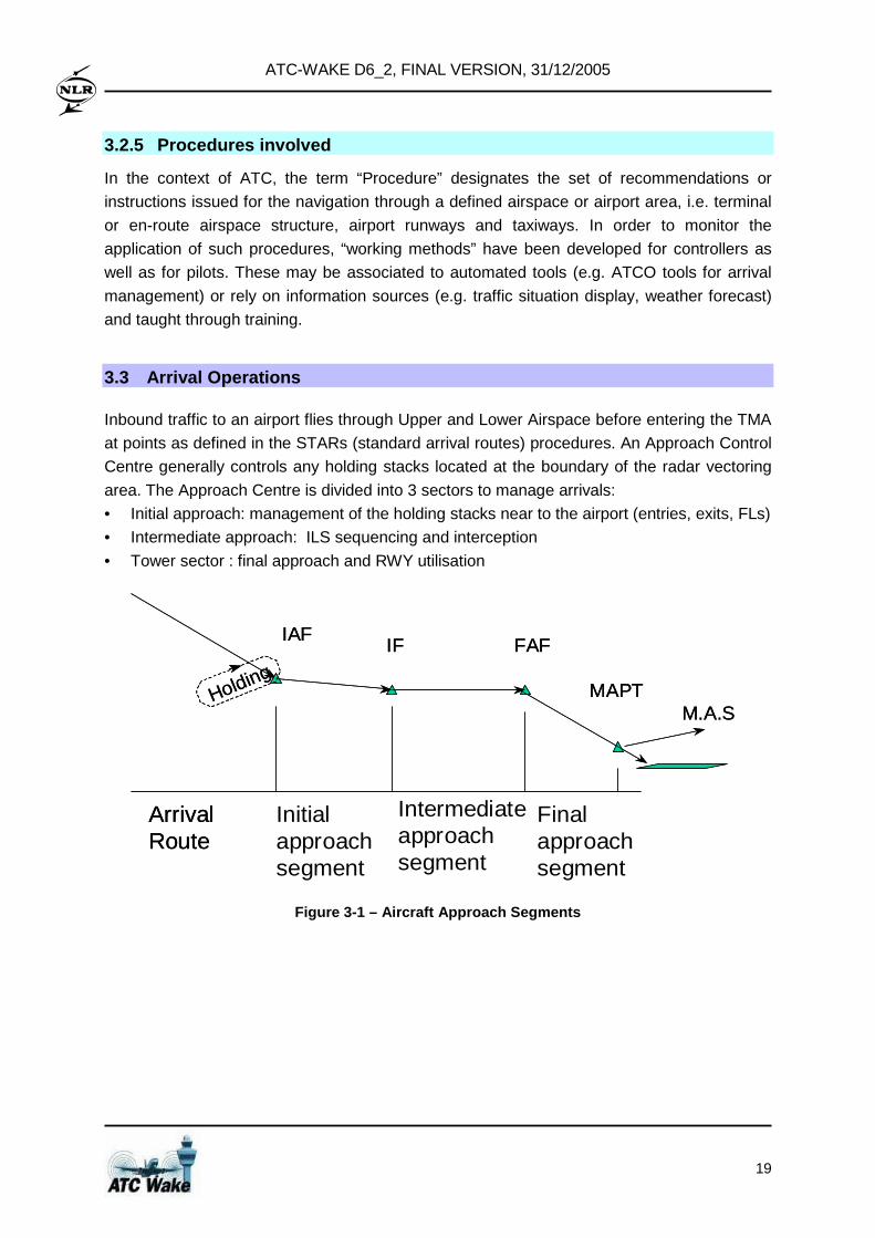
ATC-WAKE D6_2, FINAL VERSION, 31/12/2005
19
3.2.5 Procedures involved
In the context of ATC, the term “Procedure” designates the set of recommendations or
instructions issued for the navigation through a defined airspace or airport area, i.e. terminal
or en-route airspace structure, airport runways and taxiways. In order to monitor the
application of such procedures, “working methods” have been developed for controllers as
well as for pilots. These may be associated to automated tools (e.g. ATCO tools for arrival
management) or rely on information sources (e.g. traffic situation display, weather forecast)
and taught through training.
3.3 Arrival Operations
Inbound traffic to an airport flies through Upper and Lower Airspace before entering the TMA
at points as defined in the STARs (standard arrival routes) procedures. An Approach Control
Centre generally controls any holding stacks located at the boundary of the radar vectoring
area. The Approach Centre is divided into 3 sectors to manage arrivals:
• Initial approach: management of the holding stacks near to the airport (entries, exits, FLs)
• Intermediate approach: ILS sequencing and interception
• Tower sector : final approach and RWY utilisation
ArrivalRoute
MAPT
FAFIFIAF
Holding
M.A.S
ArrivalRoute
MAPT
FAFIFIAF
Holding
M.A.S
Initialapproachsegment
Intermediate approachsegment
Finalapproachsegment
Figure 3-1 – Aircraft Approach Segments
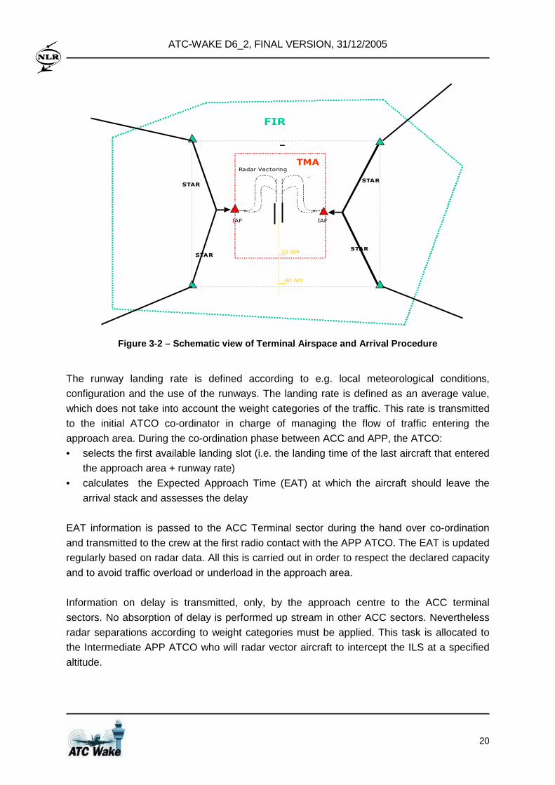
ATC-WAKE D6_2, FINAL VERSION, 31/12/2005
20
FIR
TMA
IAFIAF
Radar Vectoring
-
30 NM
STAR
STAR
STAR
STAR
80 NM
Figure 3-2 – Schematic view of Terminal Airspace an d Arrival Procedure
The runway landing rate is defined according to e.g. local meteorological conditions,
configuration and the use of the runways. The landing rate is defined as an average value,
which does not take into account the weight categories of the traffic. This rate is transmitted
to the initial ATCO co-ordinator in charge of managing the flow of traffic entering the
approach area. During the co-ordination phase between ACC and APP, the ATCO:
• selects the first available landing slot (i.e. the landing time of the last aircraft that entered
the approach area + runway rate)
• calculates the Expected Approach Time (EAT) at which the aircraft should leave the
arrival stack and assesses the delay
EAT information is passed to the ACC Terminal sector during the hand over co-ordination
and transmitted to the crew at the first radio contact with the APP ATCO. The EAT is updated
regularly based on radar data. All this is carried out in order to respect the declared capacity
and to avoid traffic overload or underload in the approach area.
Information on delay is transmitted, only, by the approach centre to the ACC terminal
sectors. No absorption of delay is performed up stream in other ACC sectors. Nevertheless
radar separations according to weight categories must be applied. This task is allocated to
the Intermediate APP ATCO who will radar vector aircraft to intercept the ILS at a specified
altitude.
ATC-WAKE D6_2, FINAL VERSION, 31/12/2005
21
3.3.1.1 Departure Operations
On runways dedicated to take-offs, the basic rules for separation are based on time if air
traffic control is provided in a non-radar environment. If the first aircraft taking-off is a
“heavy”, then take-off clearance for the following aircraft is issued after a delay of 2 minutes
irrespective of its weight category. The same time separation is applied in the case of a
“light” aircraft taking-off behind a “medium” aircraft. If an intermediate taxiway take-off is
used, the time separation between a “heavy” aircraft and other categories and between
“medium” aircraft and “light” aircraft is increased up to 3 minutes.
Pilots are well aware of the danger of Wake turbulence effects and are reluctant to shorten
this time separation even if there is a crosswind above 15 Kt.
3.3.1.2 Application of Reduced Wake vortex Separati on
Reduction of separation minima is authorised in certain cases to cope with the increasing
traffic and to enable airports to make the best use of possible capacity while maintaining the
same level of safety. Examples of reduced separation working methods are “land-after” and
“anticipated-landing”. They are applied under specific conditions, where the authorisation is
given to an aircraft to land while the preceding aircraft has still not vacated the runway. As
specified by ICAO PANS-ATM, such working methods are only applied when visual contact
between aircraft is established (and are dependent on flight crew agreement).
3.4 Users or involved actors
At present, different roles of the Air Traffic Controllers exist depending on responsibilities and
assigned airspace. The involved actors are:
• ATC Supervisor
• Planning Operations ATCOs : Arrival Sequence Manager
• Tactical Operations ATCOs
• Approach Controller : Initial / Intermediate / Final
• Tower Controller
• Ground Controller
These users may be supported by automated systems, including Arrival Managers (AMAN)
or Departure Managers (DMAN).
3.5 Justification for and Nature of Changes
3.5.1 Justification for Changes
Before 1970, aircraft of similar weights and low traffic density mitigated the risk of Wake
vortex encounters. In 1970 and during the following years some Wake vortex related
ATC-WAKE D6_2, FINAL VERSION, 31/12/2005
22
incidents occurred due to the introduction of the Boeing 747 and the constant traffic growth.
Between 1969 and 1976, extensive collection of data led to the definition of the ICAO
separation standards based on aircraft maximum takeoff weight classes. As recognised by
Aviation Stakeholders and investigated during intensive flight trials (AVOSS trials performed
by NASA), the main issues affecting ICAO Wake Vortex standard separations are:
• Over-conservative standard separation is applied in a majority of cases
• Insufficient standard separation is applied in a minority of cases
• Inappropriate regulation for closely spaced parallel runways : which results in inefficient
use of some runway configurations
In current ATC operations, no exchange of information concerning Wake vortex is provided
between ATC and Aircrews, specific procedures exist only for the heaviest freight aircraft
(Beluga, AN-22). As a consequence there is no system integrating all the sources of WV related information together at a single source, accessible by all ATC service providers (en-
route, approach, tower and arrival/departure managers).
Since new high capacity aircraft will be heavier and larger, and air traffic grows continuously
at a rate of 5 % per year, today’s aircraft separation rules are considered to be increasingly
inefficient, and may result in unnecessary delays. New weather based rules used in
combination with a suitable ATC decision support system are expected to provide the means
to significantly enhance airport capacity. Since 1993, several European Union research and
development programmes have been launched to get better knowledge of the physical and
safety aspects of the Wake vortex phenomena and to develop technologies for Wake vortex
detection and prediction. Taking benefit of such technologies, an objective of ATC-Wake was
to develop and validate operational concepts for approach and departure phases of aircraft,
while maintaining and ensuring an appropriate and required level of safety.
3.5.2 Priority Among Changes
As shown by recent surveys of Wake Vortex accidents, a majority of wake vortex encounters
happen during the final approach or the initial climb and flight crews agree that during these
flight phases near the ground, WV encounter is the most hazardous.
Wake Vortex behaviour is characterised by transport and decay, both are highly dependent
on atmospheric conditions. In the context of ATC-Wake both effects have been considered
but the preferred situation is when WV is transported out of the concerned airspace area.
The main changes introduced by ATC-Wake operations are:
• In planning operations: determination of safe aircraft separation minima using Wake
vortex prediction information (enhanced with present detection information).
• In tactical operations: application of and transition between pre-determined separation
minima.
ATC-WAKE D6_2, FINAL VERSION, 31/12/2005
23
3.5.3 Changes Considered but not Included
Alternatives for approach operations using Wake Vortex information have been identified, in
particular in the case of closely spaced parallel runways (CSPR):
• simultaneous parallel approaches : SOIA concept developed by FAA
• displacement of threshold : HALS – DTOP developed by DFS.
In addition, the application of dynamic or individual aircraft separations according to aircraft
type and Meteorological conditions has not been retained. In ATC-Wake operations, a pre-
determined aircraft separation is to be applied to the whole traffic during a specified
timeframe.
3.5.4 Assumptions and Constraints
The prediction of Wake vortex behaviour in ATC-Wake will be performed by combining met
forecast and now-cast and real-time Wake vortex measurements on airport arrivals and
departures. The quality of Wake Vortex prediction is directly related to the quality of input
data (e.g. meteorological data, radar data). A safety buffer has to be applied to satisfy
accuracy and stability requirements of ATC users. • Accuracy : covers the properties of the predicted Wake Vortex behaviour, especially
within the critical arrival / departure areas
• Stability : covers the associated timeframe to prediction, i.e. sudden changes to start /
end time(s) for application of reduced separations shall be avoided in order not to create
hazardous situations (e.g. re-organisation of arrival sequence) or constraints (flight
holding)
Quantified values for accuracy and stability attributes will need to be evaluated during the
ATC-Wake operational feasibility evaluation. The main principles followed for the calculation
of the Wake vortex behaviour in the context of ATC-Wake are the following :
• The aircraft weight and speed define the strength of the produced vortices (expressed as
the circulation m²/s).
• The turbulence (measured as the Turbulent Kinetic Energy (TKE) or Eddy Dissipation
Rate (EDR) level of the atmosphere at the vortex location) and temperature stratification
control vortex decay. Constant background shear may prolong vortex lifetimes slightly.
• The aircraft span defines the initial vortex spacing
• The vortex circulation and the spacing determine the self-induced velocity and thus the
sink rate.
• The atmosphere stratification (function of the temperature profile) can obstruct or slow
down the sinking of Wake
• The (cross and head) wind profile induce the vortex transport
• The wind shear can induce a vortex tilting. One of the two vortices may stall or rebound
and the other continues to descend .
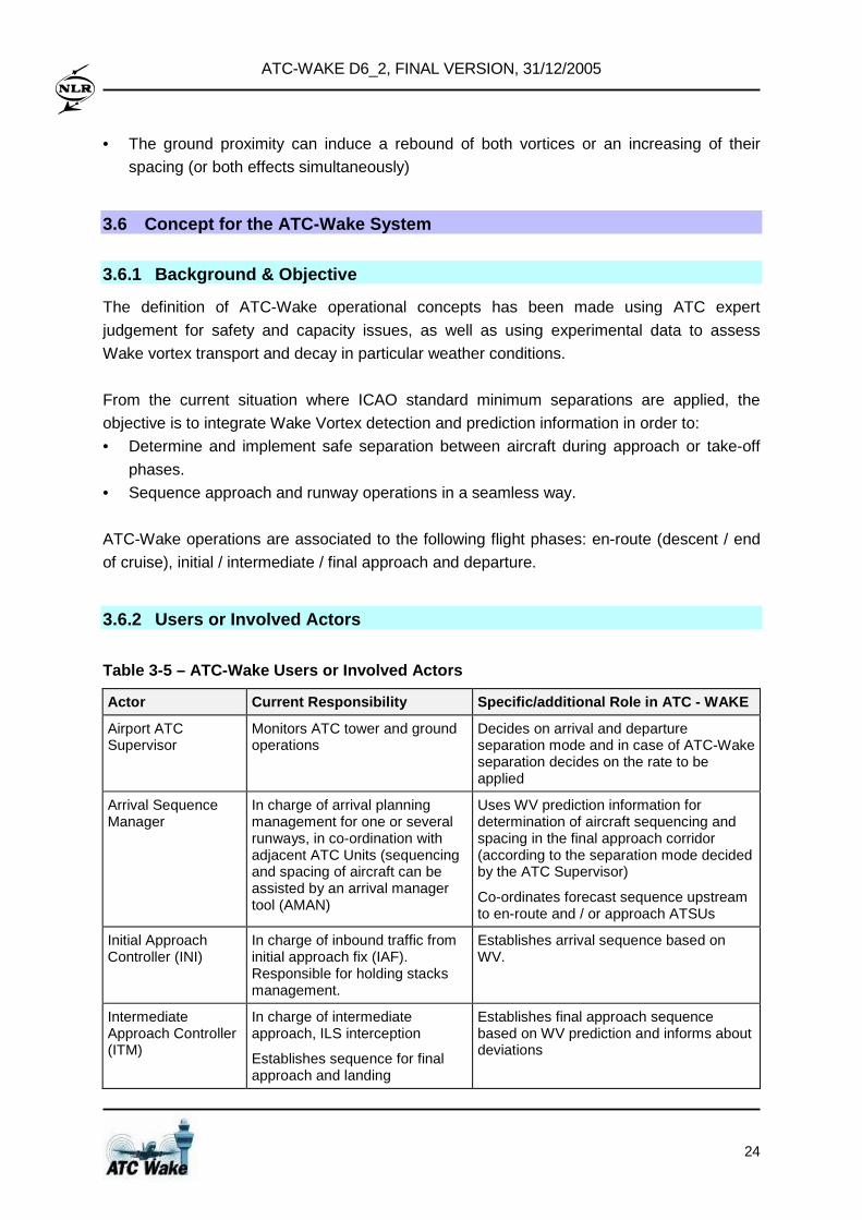
ATC-WAKE D6_2, FINAL VERSION, 31/12/2005
24
• The ground proximity can induce a rebound of both vortices or an increasing of their
spacing (or both effects simultaneously)
3.6 Concept for the ATC-Wake System
3.6.1 Background & Objective
The definition of ATC-Wake operational concepts has been made using ATC expert
judgement for safety and capacity issues, as well as using experimental data to assess
Wake vortex transport and decay in particular weather conditions.
From the current situation where ICAO standard minimum separations are applied, the
objective is to integrate Wake Vortex detection and prediction information in order to:
• Determine and implement safe separation between aircraft during approach or take-off
phases.
• Sequence approach and runway operations in a seamless way.
ATC-Wake operations are associated to the following flight phases: en-route (descent / end
of cruise), initial / intermediate / final approach and departure.
3.6.2 Users or Involved Actors
Table 3-5 – ATC-Wake Users or Involved Actors
Actor Current Responsibility Specific/additional Role in ATC - WAKE
Airport ATC Supervisor
Monitors ATC tower and ground operations
Decides on arrival and departure separation mode and in case of ATC-Wake separation decides on the rate to be applied
Arrival Sequence Manager
In charge of arrival planning management for one or several runways, in co-ordination with adjacent ATC Units (sequencing and spacing of aircraft can be assisted by an arrival manager tool (AMAN)
Uses WV prediction information for determination of aircraft sequencing and spacing in the final approach corridor (according to the separation mode decided by the ATC Supervisor)
Co-ordinates forecast sequence upstream to en-route and / or approach ATSUs
Initial Approach Controller (INI)
In charge of inbound traffic from initial approach fix (IAF). Responsible for holding stacks management.
Establishes arrival sequence based on WV.
Intermediate Approach Controller (ITM)
In charge of intermediate approach, ILS interception
Establishes sequence for final approach and landing
Establishes final approach sequence based on WV prediction and informs about deviations
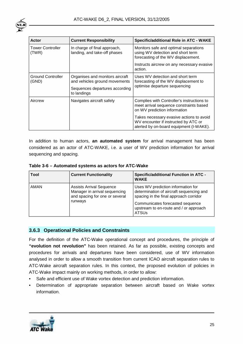
ATC-WAKE D6_2, FINAL VERSION, 31/12/2005
25
Actor Current Responsibility Specific/additional Role in ATC - WAKE
Tower Controller (TWR)
In charge of final approach, landing, and take-off phases
Monitors safe and optimal separations using WV detection and short term forecasting of the WV displacement.
Instructs aircrew on any necessary evasive action.
Ground Controller (GND)
Organises and monitors aircraft and vehicles ground movements
Sequences departures according to landings
Uses WV detection and short term forecasting of the WV displacement to optimise departure sequencing
Aircrew Navigates aircraft safely Complies with Controller’s instructions to meet arrival sequence constraints based on WV prediction information
Takes necessary evasive actions to avoid WV encounter if instructed by ATC or alerted by on-board equipment (I-WAKE).
In addition to human actors, an automated system for arrival management has been
considered as an actor of ATC-WAKE, i.e. a user of WV prediction information for arrival
sequencing and spacing.
Table 3-6 – Automated systems as actors for ATC-Wak e
Tool Current Functionality Specific/additional Function in ATC - WAKE
AMAN Assists Arrival Sequence Manager in arrival sequencing and spacing for one or several runways
Uses WV prediction information for determination of aircraft sequencing and spacing in the final approach corridor
Communicates forecasted sequence upstream to en-route and / or approach ATSUs
3.6.3 Operational Policies and Constraints
For the definition of the ATC-Wake operational concept and procedures, the principle of “evolution not revolution” has been retained. As far as possible, existing concepts and
procedures for arrivals and departures have been considered, use of WV information
analysed in order to allow a smooth transition from current ICAO aircraft separation rules to
ATC-Wake aircraft separation rules. In this context, the proposed evolution of policies in
ATC-Wake impact mainly on working methods, in order to allow:
• Safe and efficient use of Wake vortex detection and prediction information.
• Determination of appropriate separation between aircraft based on Wake vortex
information.
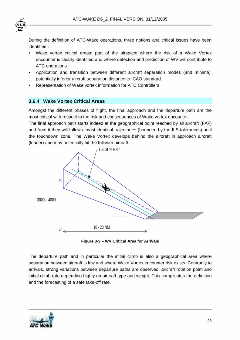
ATC-WAKE D6_2, FINAL VERSION, 31/12/2005
26
During the definition of ATC-Wake operations, three notions and critical issues have been
identified :
• Wake vortex critical areas: part of the airspace where the risk of a Wake Vortex
encounter is clearly identified and where detection and prediction of WV will contribute to
ATC operations.
• Application and transition between different aircraft separation modes (and minima):
potentially inferior aircraft separation distance to ICAO standard.
• Representation of Wake vortex information for ATC Controllers.
3.6.4 Wake Vortex Critical Areas
Amongst the different phases of flight, the final approach and the departure path are the
most critical with respect to the risk and consequences of Wake vortex encounter.
The final approach path starts indeed at the geographical point reached by all aircraft (FAF)
and from it they will follow almost identical trajectories (bounded by the ILS tolerances) until
the touchdown zone. The Wake Vortex develops behind the aircraft in approach aircraft
(leader) and may potentially hit the follower aircraft.
10 - 20 NM
ILS Glide Path
3000 – 4000 ft
Figure 3-3 – WV Critical Area for Arrivals
The departure path and in particular the initial climb is also a geographical area where
separation between aircraft is low and where Wake Vortex encounter risk exists. Contrarily to
arrivals, strong variations between departure paths are observed, aircraft rotation point and
initial climb rate depending highly on aircraft type and weight. This complicates the definition
and the forecasting of a safe take-off rate.
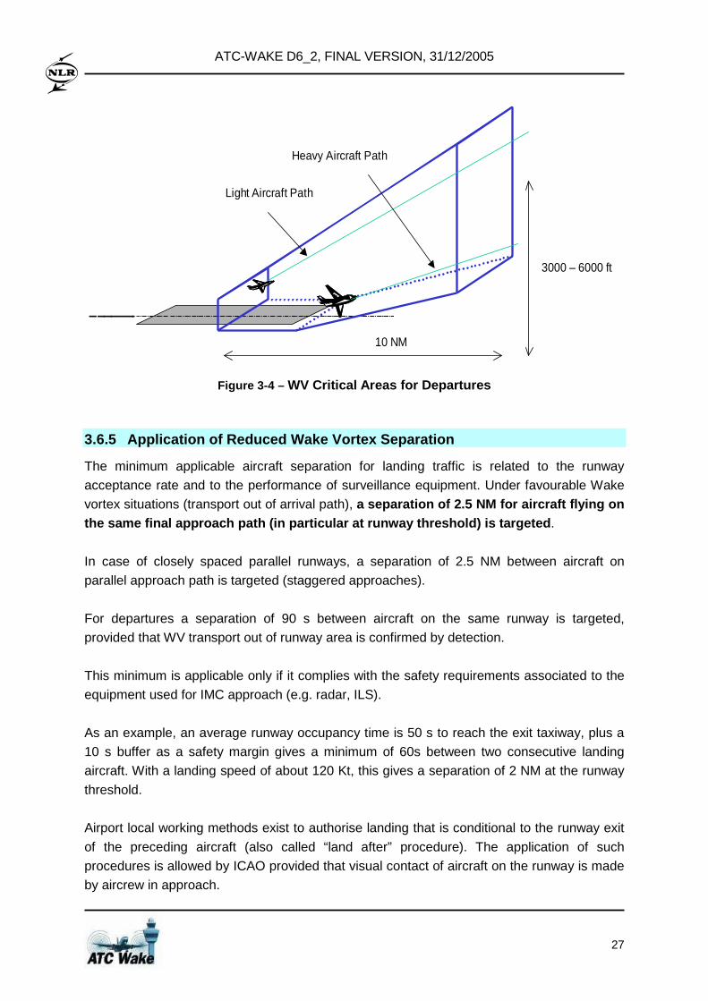
ATC-WAKE D6_2, FINAL VERSION, 31/12/2005
27
10 NM
3000 – 6000 ft
Light Aircraft Path
Heavy Aircraft Path
Figure 3-4 – WV Critical Areas for Departures
3.6.5 Application of Reduced Wake Vortex Separation
The minimum applicable aircraft separation for landing traffic is related to the runway
acceptance rate and to the performance of surveillance equipment. Under favourable Wake
vortex situations (transport out of arrival path), a separation of 2.5 NM for aircraft flying on the same final approach path (in particular at runw ay threshold) is targeted .
In case of closely spaced parallel runways, a separation of 2.5 NM between aircraft on
parallel approach path is targeted (staggered approaches).
For departures a separation of 90 s between aircraft on the same runway is targeted,
provided that WV transport out of runway area is confirmed by detection.
This minimum is applicable only if it complies with the safety requirements associated to the
equipment used for IMC approach (e.g. radar, ILS).
As an example, an average runway occupancy time is 50 s to reach the exit taxiway, plus a
10 s buffer as a safety margin gives a minimum of 60s between two consecutive landing
aircraft. With a landing speed of about 120 Kt, this gives a separation of 2 NM at the runway
threshold.
Airport local working methods exist to authorise landing that is conditional to the runway exit
of the preceding aircraft (also called “land after” procedure). The application of such
procedures is allowed by ICAO provided that visual contact of aircraft on the runway is made
by aircrew in approach.
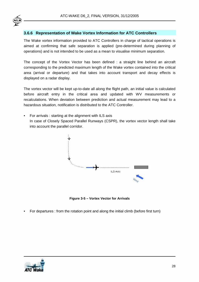
ATC-WAKE D6_2, FINAL VERSION, 31/12/2005
28
3.6.6 Representation of Wake Vortex Information for ATC Controllers
The Wake vortex information provided to ATC Controllers in charge of tactical operations is
aimed at confirming that safe separation is applied (pre-determined during planning of
operations) and is not intended to be used as a mean to visualise minimum separation.
The concept of the Vortex Vector has been defined : a straight line behind an aircraft
corresponding to the predicted maximum length of the Wake vortex contained into the critical
area (arrival or departure) and that takes into account transport and decay effects is
displayed on a radar display.
The vortex vector will be kept up-to-date all along the flight path, an initial value is calculated
before aircraft entry in the critical area and updated with WV measurements or
recalculations. When deviation between prediction and actual measurement may lead to a
hazardous situation, notification is distributed to the ATC Controller.
• For arrivals : starting at the alignment with ILS axis
In case of Closely Spaced Parallel Runways (CSPR), the vortex vector length shall take
into account the parallel corridor.
Figure 3-5 – Vortex Vector for Arrivals
• For departures : from the rotation point and along the initial climb (before first turn)
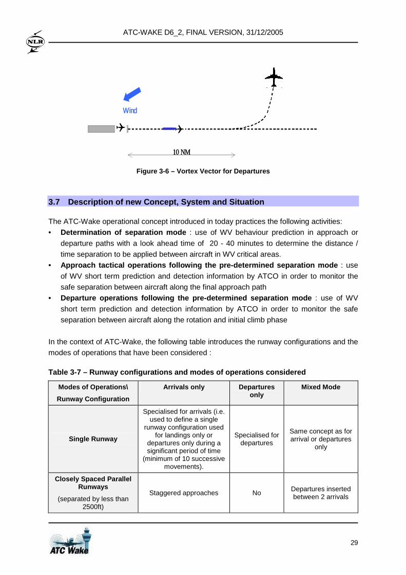
ATC-WAKE D6_2, FINAL VERSION, 31/12/2005
29
Wind
10 NM
Wind
10 NM
Figure 3-6 – Vortex Vector for Departures
3.7 Description of new Concept, System and Situatio n
The ATC-Wake operational concept introduced in today practices the following activities:
• Determination of separation mode : use of WV behaviour prediction in approach or
departure paths with a look ahead time of 20 - 40 minutes to determine the distance /
time separation to be applied between aircraft in WV critical areas.
• Approach tactical operations following the pre-dete rmined separation mode : use
of WV short term prediction and detection information by ATCO in order to monitor the
safe separation between aircraft along the final approach path • Departure operations following the pre-determined s eparation mode : use of WV
short term prediction and detection information by ATCO in order to monitor the safe
separation between aircraft along the rotation and initial climb phase
In the context of ATC-Wake, the following table introduces the runway configurations and the
modes of operations that have been considered :
Table 3-7 – Runway configurations and modes of oper ations considered
Modes of Operations\
Runway Configuration
Arrivals only Departures only
Mixed Mode
Single Runway
Specialised for arrivals (i.e. used to define a single
runway configuration used for landings only or
departures only during a significant period of time
(minimum of 10 successive movements).
Specialised for departures
Same concept as for arrival or departures
only
Closely Spaced Parallel Runways
(separated by less than 2500ft)
Staggered approaches No Departures inserted between 2 arrivals
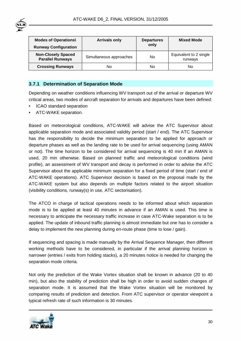
ATC-WAKE D6_2, FINAL VERSION, 31/12/2005
30
Modes of Operations\
Runway Configuration
Arrivals only Departures only
Mixed Mode
Non-Closely Spaced Parallel Runways Simultaneous approaches No
Equivalent to 2 single runways
Crossing Runways No No No
3.7.1 Determination of Separation Mode
Depending on weather conditions influencing WV transport out of the arrival or departure WV
critical areas, two modes of aircraft separation for arrivals and departures have been defined:
• ICAO standard separation
• ATC-WAKE separation.
Based on meteorological conditions, ATC-WAKE will advise the ATC Supervisor about
applicable separation mode and associated validity period (start / end). The ATC Supervisor
has the responsibility to decide the minimum separation to be applied for approach or
departure phases as well as the landing rate to be used for arrival sequencing (using AMAN
or not). The time horizon to be considered for arrival sequencing is 40 min if an AMAN is
used, 20 min otherwise. Based on planned traffic and meteorological conditions (wind
profile), an assessment of WV transport and decay is performed in order to advise the ATC
Supervisor about the applicable minimum separation for a fixed period of time (start / end of
ATC-WAKE operations). ATC Supervisor decision is based on the proposal made by the
ATC-WAKE system but also depends on multiple factors related to the airport situation
(visibility conditions, runway(s) in use, ATC sectorisation).
The ATCO in charge of tactical operations needs to be informed about which separation
mode is to be applied at least 40 minutes in advance if an AMAN is used. This time is
necessary to anticipate the necessary traffic increase in case ATC-Wake separation is to be
applied. The update of inbound traffic planning is almost immediate but one has to consider a
delay to implement the new planning during en-route phase (time to lose / gain).
If sequencing and spacing is made manually by the Arrival Sequence Manager, then different
working methods have to be considered, in particular if the arrival planning horizon is
narrower (entries / exits from holding stacks), a 20 minutes notice is needed for changing the
separation mode criteria.
Not only the prediction of the Wake Vortex situation shall be known in advance (20 to 40
min), but also the stability of prediction shall be high in order to avoid sudden changes of
separation mode. It is assumed that the Wake Vortex situation will be monitored by
comparing results of prediction and detection. From ATC supervisor or operator viewpoint a
typical refresh rate of such information is 30 minutes.
ATC-WAKE D6_2, FINAL VERSION, 31/12/2005
31
17:10
14:30
11:50
ICAO
ATC WAKE
08:20
ATC WAKE
ICAO
Arrivals : 2.5 NMDepartures : 90 s
Arrivals : 2.8 NMDepartures : 100 s
07:29 Mode transition at 07:40
17:10
14:30
11:50
ICAO
ATC WAKE
08:20
ATC WAKE
ICAO
Arrivals : 2.5 NMDepartures : 90 s
Arrivals : 2.8 NMDepartures : 100 s
07:29 Mode transition at 07:40
Brussels – 25 L / 25 R
17:1017:10
14:3014:30
11:5011:50
ICAO
ATC WAKE
08:2008:20
ATC WAKE
ICAO
Arrivals : 2.5 NMDepartures : 90 s
Arrivals : 2.8 NMDepartures : 100 s
07:29 Mode transition at 07:40
17:1017:10
14:3014:30
11:5011:50
ICAO
ATC WAKE
08:2008:20
ATC WAKE
ICAO
Arrivals : 2.5 NMDepartures : 90 s
Arrivals : 2.8 NMDepartures : 100 s
07:29 Mode transition at 07:40
Brussels – 25 L / 25 R
Figure 3-7 – Example of a Planning of Separation Mo des
3.7.2 ATC-Wake Concept for Arrival Operations
The section presents the general ATC-Wake operational concept for arrivals to be applied for
a single runway configuration. Specific operations for closely spaced parallel runways have
been considered and an example of procedure for such an operation is presented in section
3.9.3.
3.7.2.1 Planning of arrivals
Based on landing rate, AMAN and/or the Arrival Sequence Manager establishes the aircraft
arrival sequence and backward propagation is used to define entry times at IAFs. In order to
realise such a sequence at the IAF, the amount of time to lose or to gain for each flight is
determined by AMAN and displayed to the en-route Controllers for them to apply. The
determination of the time to lose is currently implemented in a number of arrival manager
tools, e.g. COMPAS (Frankfurt), OSYRIS (Zurich), MAESTRO (PARIS), CTAS (US).
However, none of them integrates Wake Vortex prediction as yet.
In the absence of an Arrival Manager, the sequence is established on a First In - First Out
(FIFO) method on entering the holding stack. More accurate spacing is then achieved by the
Initial Approach Controller by adjusting the holding time.
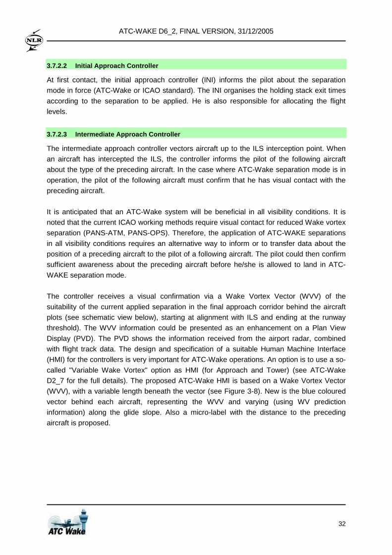
ATC-WAKE D6_2, FINAL VERSION, 31/12/2005
32
3.7.2.2 Initial Approach Controller
At first contact, the initial approach controller (INI) informs the pilot about the separation
mode in force (ATC-Wake or ICAO standard). The INI organises the holding stack exit times
according to the separation to be applied. He is also responsible for allocating the flight
levels.
3.7.2.3 Intermediate Approach Controller
The intermediate approach controller vectors aircraft up to the ILS interception point. When
an aircraft has intercepted the ILS, the controller informs the pilot of the following aircraft
about the type of the preceding aircraft. In the case where ATC-Wake separation mode is in
operation, the pilot of the following aircraft must confirm that he has visual contact with the
preceding aircraft.
It is anticipated that an ATC-Wake system will be beneficial in all visibility conditions. It is
noted that the current ICAO working methods require visual contact for reduced Wake vortex
separation (PANS-ATM, PANS-OPS). Therefore, the application of ATC-WAKE separations
in all visibility conditions requires an alternative way to inform or to transfer data about the
position of a preceding aircraft to the pilot of a following aircraft. The pilot could then confirm
sufficient awareness about the preceding aircraft before he/she is allowed to land in ATC-
WAKE separation mode.
The controller receives a visual confirmation via a Wake Vortex Vector (WVV) of the
suitability of the current applied separation in the final approach corridor behind the aircraft
plots (see schematic view below), starting at alignment with ILS and ending at the runway
threshold). The WVV information could be presented as an enhancement on a Plan View
Display (PVD). The PVD shows the information received from the airport radar, combined
with flight track data. The design and specification of a suitable Human Machine Interface
(HMI) for the controllers is very important for ATC-Wake operations. An option is to use a so-
called "Variable Wake Vortex" option as HMI (for Approach and Tower) (see ATC-Wake
D2_7 for the full details). The proposed ATC-Wake HMI is based on a Wake Vortex Vector
(WVV), with a variable length beneath the vector (see Figure 3-8). New is the blue coloured
vector behind each aircraft, representing the WVV and varying (using WV prediction
information) along the glide slope. Also a micro-label with the distance to the preceding
aircraft is proposed.
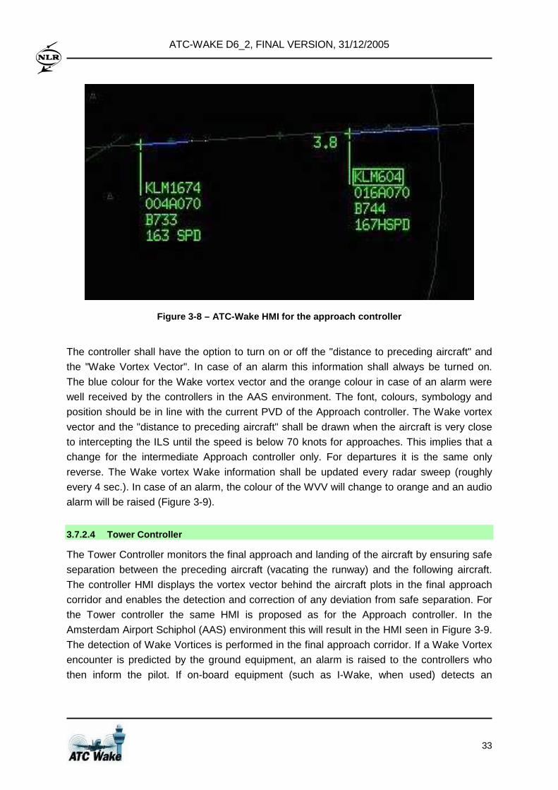
ATC-WAKE D6_2, FINAL VERSION, 31/12/2005
33
Figure 3-8 – ATC-Wake HMI for the approach controll er
The controller shall have the option to turn on or off the "distance to preceding aircraft" and
the "Wake Vortex Vector". In case of an alarm this information shall always be turned on.
The blue colour for the Wake vortex vector and the orange colour in case of an alarm were
well received by the controllers in the AAS environment. The font, colours, symbology and
position should be in line with the current PVD of the Approach controller. The Wake vortex
vector and the "distance to preceding aircraft" shall be drawn when the aircraft is very close
to intercepting the ILS until the speed is below 70 knots for approaches. This implies that a
change for the intermediate Approach controller only. For departures it is the same only
reverse. The Wake vortex Wake information shall be updated every radar sweep (roughly
every 4 sec.). In case of an alarm, the colour of the WVV will change to orange and an audio
alarm will be raised (Figure 3-9).
3.7.2.4 Tower Controller
The Tower Controller monitors the final approach and landing of the aircraft by ensuring safe
separation between the preceding aircraft (vacating the runway) and the following aircraft.
The controller HMI displays the vortex vector behind the aircraft plots in the final approach
corridor and enables the detection and correction of any deviation from safe separation. For
the Tower controller the same HMI is proposed as for the Approach controller. In the
Amsterdam Airport Schiphol (AAS) environment this will result in the HMI seen in Figure 3-9.
The detection of Wake Vortices is performed in the final approach corridor. If a Wake Vortex
encounter is predicted by the ground equipment, an alarm is raised to the controllers who
then inform the pilot. If on-board equipment (such as I-Wake, when used) detects an
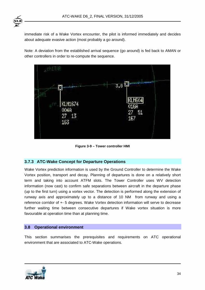
ATC-WAKE D6_2, FINAL VERSION, 31/12/2005
34
immediate risk of a Wake Vortex encounter, the pilot is informed immediately and decides
about adequate evasive action (most probably a go around).
Note: A deviation from the established arrival sequence (go around) is fed back to AMAN or
other controllers in order to re-compute the sequence.
Figure 3-9 – Tower controller HMI
3.7.3 ATC-Wake Concept for Departure Operations
Wake Vortex prediction information is used by the Ground Controller to determine the Wake
Vortex position, transport and decay. Planning of departures is done on a relatively short
term and taking into account ATFM slots. The Tower Controller uses WV detection
information (now cast) to confirm safe separations between aircraft in the departure phase
(up to the first turn) using a vortex vector. The detection is performed along the extension of
runway axis and approximately up to a distance of 10 NM from runway and using a
reference corridor of +- 5 degrees. Wake Vortex detection information will serve to decrease
further waiting time between consecutive departures if Wake vortex situation is more
favourable at operation time than at planning time.
3.8 Operational environment
This section summarises the prerequisites and requirements on ATC operational
environment that are associated to ATC-Wake operations.
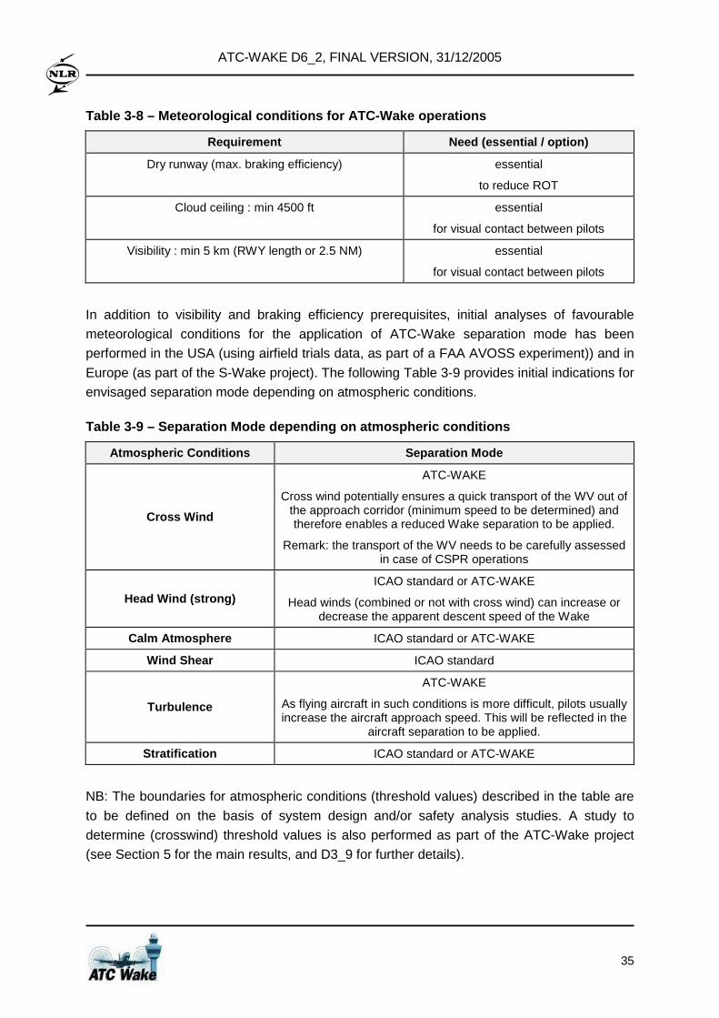
ATC-WAKE D6_2, FINAL VERSION, 31/12/2005
35
Table 3-8 – Meteorological conditions for ATC-Wake operations
Requirement Need (essential / option)
Dry runway (max. braking efficiency) essential
to reduce ROT
Cloud ceiling : min 4500 ft essential
for visual contact between pilots
Visibility : min 5 km (RWY length or 2.5 NM) essential
for visual contact between pilots
In addition to visibility and braking efficiency prerequisites, initial analyses of favourable
meteorological conditions for the application of ATC-Wake separation mode has been
performed in the USA (using airfield trials data, as part of a FAA AVOSS experiment)) and in
Europe (as part of the S-Wake project). The following Table 3-9 provides initial indications for
envisaged separation mode depending on atmospheric conditions.
Table 3-9 – Separation Mode depending on atmospheri c conditions
Atmospheric Conditions Separation Mode
Cross Wind
ATC-WAKE
Cross wind potentially ensures a quick transport of the WV out of the approach corridor (minimum speed to be determined) and therefore enables a reduced Wake separation to be applied.
Remark: the transport of the WV needs to be carefully assessed in case of CSPR operations
Head Wind (strong) ICAO standard or ATC-WAKE
Head winds (combined or not with cross wind) can increase or decrease the apparent descent speed of the Wake
Calm Atmosphere ICAO standard or ATC-WAKE
Wind Shear ICAO standard
Turbulence
ATC-WAKE
As flying aircraft in such conditions is more difficult, pilots usually increase the aircraft approach speed. This will be reflected in the
aircraft separation to be applied.
Stratification ICAO standard or ATC-WAKE
NB: The boundaries for atmospheric conditions (threshold values) described in the table are
to be defined on the basis of system design and/or safety analysis studies. A study to
determine (crosswind) threshold values is also performed as part of the ATC-Wake project
(see Section 5 for the main results, and D3_9 for further details).
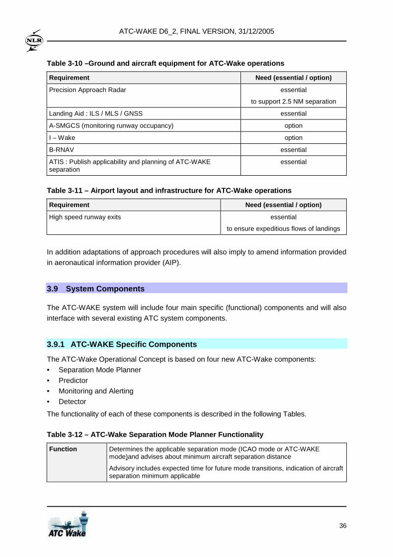
ATC-WAKE D6_2, FINAL VERSION, 31/12/2005
36
Table 3-10 –Ground and aircraft equipment for ATC-W ake operations
Requirement Need (essential / option)
Precision Approach Radar essential
to support 2.5 NM separation
Landing Aid : ILS / MLS / GNSS essential
A-SMGCS (monitoring runway occupancy) option
I – Wake option
B-RNAV essential
ATIS : Publish applicability and planning of ATC-WAKE separation
essential
Table 3-11 – Airport layout and infrastructure for ATC-Wake operations
Requirement Need (essential / option)
High speed runway exits essential
to ensure expeditious flows of landings
In addition adaptations of approach procedures will also imply to amend information provided
in aeronautical information provider (AIP).
3.9 System Components
The ATC-WAKE system will include four main specific (functional) components and will also
interface with several existing ATC system components.
3.9.1 ATC-WAKE Specific Components
The ATC-Wake Operational Concept is based on four new ATC-Wake components:
• Separation Mode Planner
• Predictor
• Monitoring and Alerting
• Detector
The functionality of each of these components is described in the following Tables.
Table 3-12 – ATC-Wake Separation Mode Planner Funct ionality
Function Determines the applicable separation mode (ICAO mode or ATC-WAKE mode)and advises about minimum aircraft separation distance
Advisory includes expected time for future mode transitions, indication of aircraft separation minimum applicable
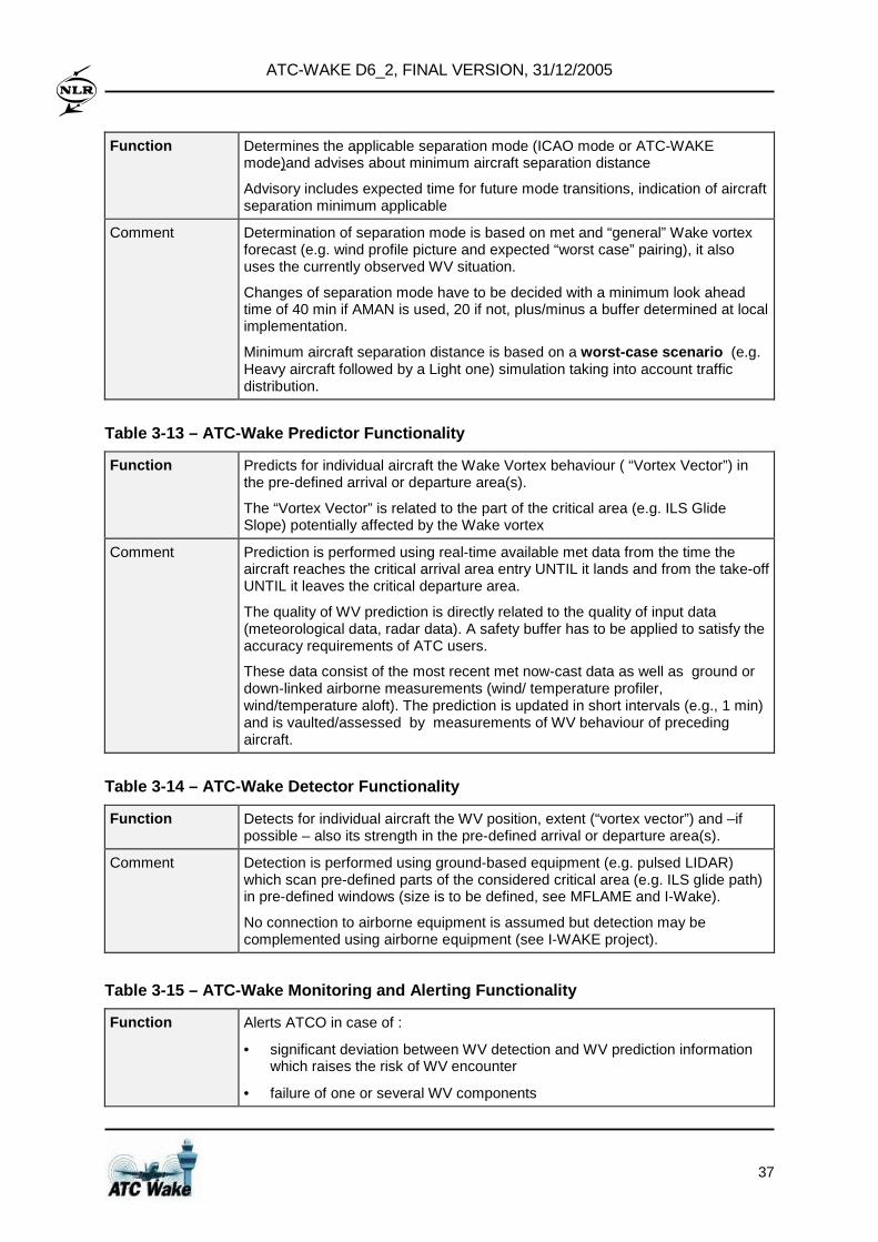
ATC-WAKE D6_2, FINAL VERSION, 31/12/2005
37
Function Determines the applicable separation mode (ICAO mode or ATC-WAKE mode)and advises about minimum aircraft separation distance
Advisory includes expected time for future mode transitions, indication of aircraft separation minimum applicable
Comment Determination of separation mode is based on met and “general” Wake vortex forecast (e.g. wind profile picture and expected “worst case” pairing), it also uses the currently observed WV situation.
Changes of separation mode have to be decided with a minimum look ahead time of 40 min if AMAN is used, 20 if not, plus/minus a buffer determined at local implementation.
Minimum aircraft separation distance is based on a worst-case scenario (e.g. Heavy aircraft followed by a Light one) simulation taking into account traffic distribution.
Table 3-13 – ATC-Wake Predictor Functionality
Function Predicts for individual aircraft the Wake Vortex behaviour ( “Vortex Vector”) in the pre-defined arrival or departure area(s).
The “Vortex Vector” is related to the part of the critical area (e.g. ILS Glide Slope) potentially affected by the Wake vortex
Comment Prediction is performed using real-time available met data from the time the aircraft reaches the critical arrival area entry UNTIL it lands and from the take-off UNTIL it leaves the critical departure area.
The quality of WV prediction is directly related to the quality of input data (meteorological data, radar data). A safety buffer has to be applied to satisfy the accuracy requirements of ATC users.
These data consist of the most recent met now-cast data as well as ground or down-linked airborne measurements (wind/ temperature profiler, wind/temperature aloft). The prediction is updated in short intervals (e.g., 1 min) and is vaulted/assessed by measurements of WV behaviour of preceding aircraft.
Table 3-14 – ATC-Wake Detector Functionality
Function Detects for individual aircraft the WV position, extent (“vortex vector”) and –if possible – also its strength in the pre-defined arrival or departure area(s).
Comment Detection is performed using ground-based equipment (e.g. pulsed LIDAR) which scan pre-defined parts of the considered critical area (e.g. ILS glide path) in pre-defined windows (size is to be defined, see MFLAME and I-Wake).
No connection to airborne equipment is assumed but detection may be complemented using airborne equipment (see I-WAKE project).
Table 3-15 – ATC-Wake Monitoring and Alerting Funct ionality
Function Alerts ATCO in case of :
• significant deviation between WV detection and WV prediction information which raises the risk of WV encounter
• failure of one or several WV components
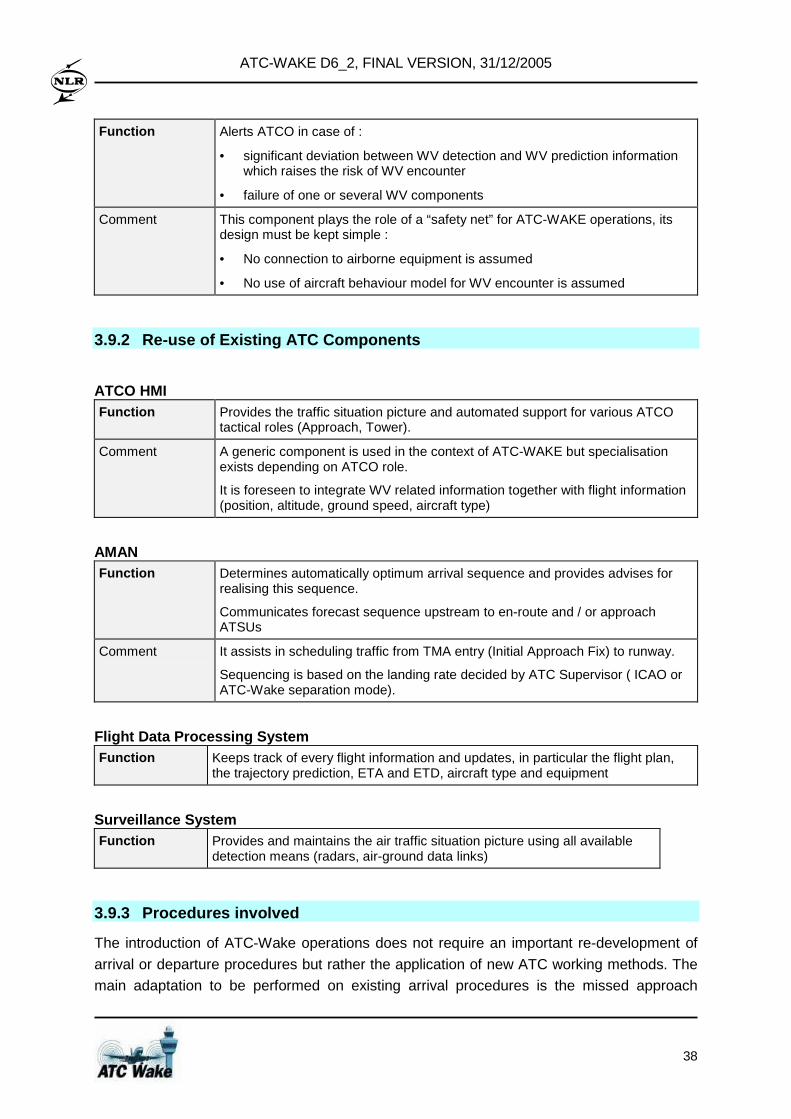
ATC-WAKE D6_2, FINAL VERSION, 31/12/2005
38
Function Alerts ATCO in case of :
• significant deviation between WV detection and WV prediction information which raises the risk of WV encounter
• failure of one or several WV components
Comment This component plays the role of a “safety net” for ATC-WAKE operations, its design must be kept simple :
• No connection to airborne equipment is assumed
• No use of aircraft behaviour model for WV encounter is assumed
3.9.2 Re-use of Existing ATC Components
ATCO HMI Function Provides the traffic situation picture and automated support for various ATCO
tactical roles (Approach, Tower).
Comment A generic component is used in the context of ATC-WAKE but specialisation exists depending on ATCO role.
It is foreseen to integrate WV related information together with flight information (position, altitude, ground speed, aircraft type)
AMAN Function Determines automatically optimum arrival sequence and provides advises for
realising this sequence.
Communicates forecast sequence upstream to en-route and / or approach ATSUs
Comment It assists in scheduling traffic from TMA entry (Initial Approach Fix) to runway.
Sequencing is based on the landing rate decided by ATC Supervisor ( ICAO or ATC-Wake separation mode).
Flight Data Processing System Function Keeps track of every flight information and updates, in particular the flight plan,
the trajectory prediction, ETA and ETD, aircraft type and equipment
Surveillance System Function Provides and maintains the air traffic situation picture using all available
detection means (radars, air-ground data links)
3.9.3 Procedures involved
The introduction of ATC-Wake operations does not require an important re-development of
arrival or departure procedures but rather the application of new ATC working methods. The
main adaptation to be performed on existing arrival procedures is the missed approach
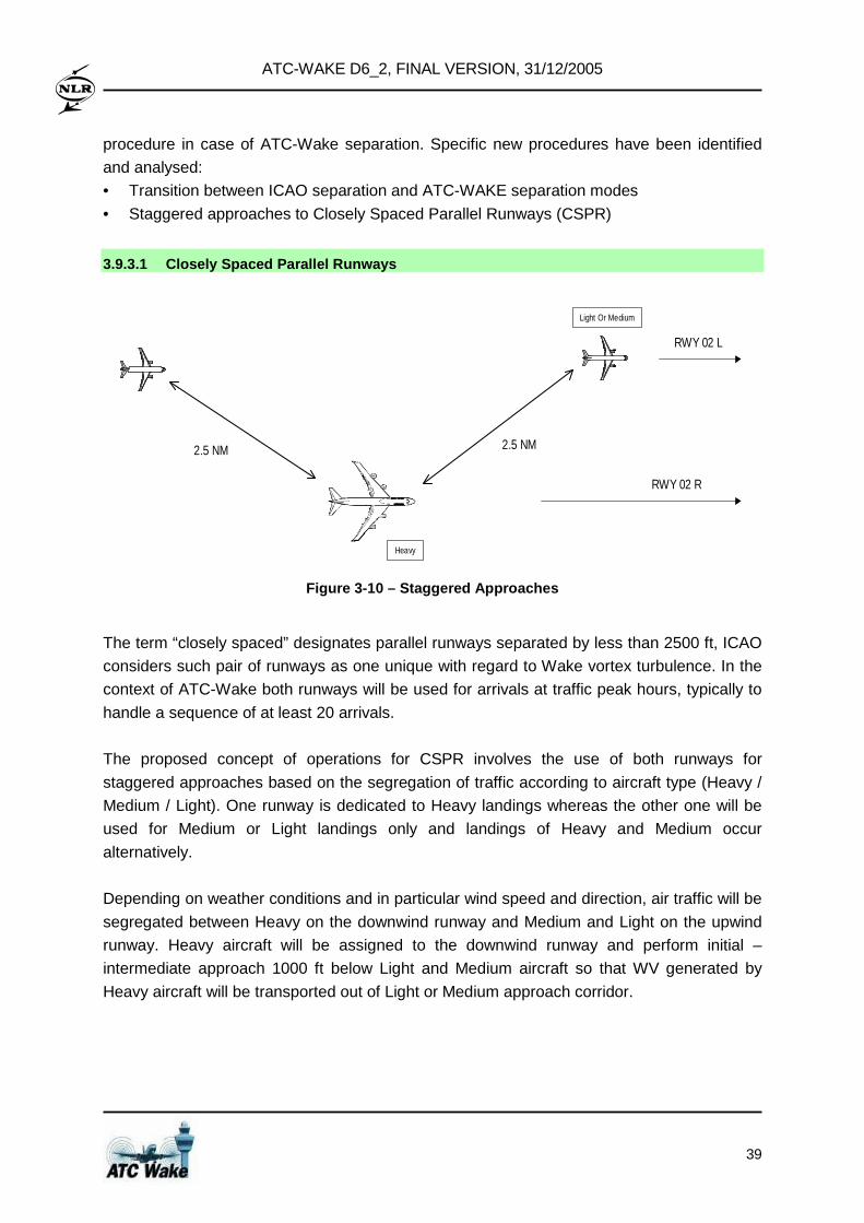
ATC-WAKE D6_2, FINAL VERSION, 31/12/2005
39
procedure in case of ATC-Wake separation. Specific new procedures have been identified
and analysed:
• Transition between ICAO separation and ATC-WAKE separation modes
• Staggered approaches to Closely Spaced Parallel Runways (CSPR)
3.9.3.1 Closely Spaced Parallel Runways
2.5 NM2.5 NM
RWY 02 L
RWY 02 R
Heavy
Light Or Medium
Figure 3-10 – Staggered Approaches
The term “closely spaced” designates parallel runways separated by less than 2500 ft, ICAO
considers such pair of runways as one unique with regard to Wake vortex turbulence. In the
context of ATC-Wake both runways will be used for arrivals at traffic peak hours, typically to
handle a sequence of at least 20 arrivals.
The proposed concept of operations for CSPR involves the use of both runways for
staggered approaches based on the segregation of traffic according to aircraft type (Heavy /
Medium / Light). One runway is dedicated to Heavy landings whereas the other one will be
used for Medium or Light landings only and landings of Heavy and Medium occur
alternatively.
Depending on weather conditions and in particular wind speed and direction, air traffic will be
segregated between Heavy on the downwind runway and Medium and Light on the upwind
runway. Heavy aircraft will be assigned to the downwind runway and perform initial –
intermediate approach 1000 ft below Light and Medium aircraft so that WV generated by
Heavy aircraft will be transported out of Light or Medium approach corridor.
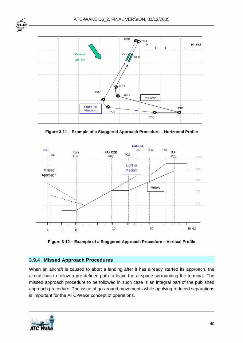
ATC-WAKE D6_2, FINAL VERSION, 31/12/2005
40
02R
0 10 NM0 10 NM
P01
P04
P02
P03
02L
P05
P06
P07
P08
Wind
15 Kt
Light or Medium
Heavy
Figure 3-11 – Example of a Staggered Approach Proce dure – Horizontal Profile
1000
3000
5000
7000
9000 ft
0 1024
IAFP01
FAF O2RP03
RWY THR P02P04
P05P06FAF O2L
P07
0 20 30 NM
P08
Heavy
Light or MediumMissed
Approach
Figure 3-12 – Example of a Staggered Approach Proce dure – Vertical Profile
3.9.4 Missed Approach Procedures
When an aircraft is caused to abort a landing after it has already started its approach, the
aircraft has to follow a pre-defined path to leave the airspace surrounding the terminal. The
missed approach procedure to be followed in such case is an integral part of the published
approach procedure. The issue of go-around movements while applying reduced separations
is important for the ATC-Wake concept of operations.
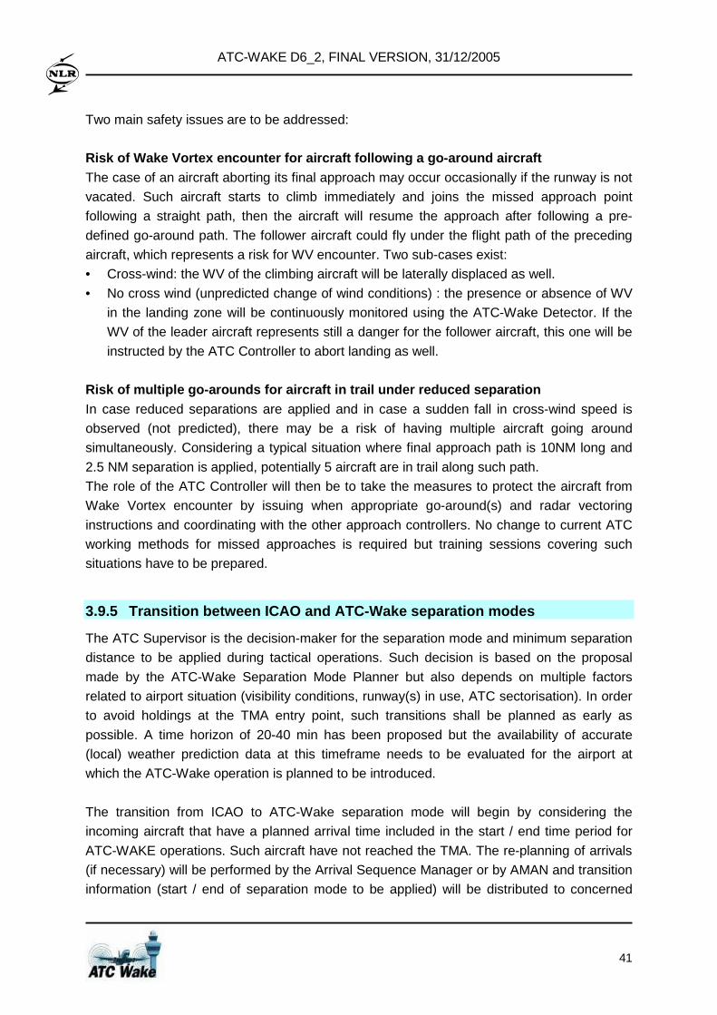
ATC-WAKE D6_2, FINAL VERSION, 31/12/2005
41
Two main safety issues are to be addressed:
Risk of Wake Vortex encounter for aircraft followin g a go-around aircraft The case of an aircraft aborting its final approach may occur occasionally if the runway is not
vacated. Such aircraft starts to climb immediately and joins the missed approach point
following a straight path, then the aircraft will resume the approach after following a pre-
defined go-around path. The follower aircraft could fly under the flight path of the preceding
aircraft, which represents a risk for WV encounter. Two sub-cases exist:
• Cross-wind: the WV of the climbing aircraft will be laterally displaced as well.
• No cross wind (unpredicted change of wind conditions) : the presence or absence of WV
in the landing zone will be continuously monitored using the ATC-Wake Detector. If the
WV of the leader aircraft represents still a danger for the follower aircraft, this one will be
instructed by the ATC Controller to abort landing as well.
Risk of multiple go-arounds for aircraft in trail u nder reduced separation In case reduced separations are applied and in case a sudden fall in cross-wind speed is
observed (not predicted), there may be a risk of having multiple aircraft going around
simultaneously. Considering a typical situation where final approach path is 10NM long and
2.5 NM separation is applied, potentially 5 aircraft are in trail along such path.
The role of the ATC Controller will then be to take the measures to protect the aircraft from
Wake Vortex encounter by issuing when appropriate go-around(s) and radar vectoring
instructions and coordinating with the other approach controllers. No change to current ATC
working methods for missed approaches is required but training sessions covering such
situations have to be prepared.
3.9.5 Transition between ICAO and ATC-Wake separati on modes
The ATC Supervisor is the decision-maker for the separation mode and minimum separation
distance to be applied during tactical operations. Such decision is based on the proposal
made by the ATC-Wake Separation Mode Planner but also depends on multiple factors
related to airport situation (visibility conditions, runway(s) in use, ATC sectorisation). In order
to avoid holdings at the TMA entry point, such transitions shall be planned as early as
possible. A time horizon of 20-40 min has been proposed but the availability of accurate
(local) weather prediction data at this timeframe needs to be evaluated for the airport at
which the ATC-Wake operation is planned to be introduced.
The transition from ICAO to ATC-Wake separation mode will begin by considering the
incoming aircraft that have a planned arrival time included in the start / end time period for
ATC-WAKE operations. Such aircraft have not reached the TMA. The re-planning of arrivals
(if necessary) will be performed by the Arrival Sequence Manager or by AMAN and transition
information (start / end of separation mode to be applied) will be distributed to concerned
ATC-WAKE D6_2, FINAL VERSION, 31/12/2005
42
ATCOs. The time adjustments will be implemented by en-route controllers through speed
modifications, radar monitoring or/and holding pattern.
For departures, transition will not imply immediate actions but transition information will be
distributed to concerned ATCOs. In case of an unexpected change of meteorological
conditions or in case of ATC-Wake equipment failure, the application of larger separation on
short term (less than 10 minutes) is required, a procedure to reverse back to ICAO
separation has to be defined.
3.10 Evaluation of the ATC-Wake concept and require ments
As a first step towards use of an ATC-Wake system at airports, the WP1000 on System
Requirements (D1_5) has established the ATC-Wake operational concept and requirements
for the application of reduced aircraft separation under favourable weather conditions. A
(high-level) overview of ATC-Wake operational requirements, users requirements, and
system requirements is provided in Appendix A. During the development of the requirements,
a number of key issues have been identified:
• Transitions between ATC-Wake and ICAO separation mo des
Frequent transitions between ICAO and ATC-Wake separation modes may have a
negative effect on capacity as such event potentially requires significant ATC resource for
the re-planning of arrivals. Quantified values for the accuracy of WV predictions and the
stability of the wind predictions will need to be established.
• Aircraft separation and sector loading
The definition of reduced aircraft separation (the ATC-Wake Mode of Operation) has
been evaluated based on typical figures for individual runway occupancy time. In the
case of large airports with three to four active runways, the effect of increased throughput
on TMA traffic load needs to be further examined. An adequate strategy for the
application of reduced wake vortex separation together with TMA sectorisation plan will
need to be established.
• Missed approaches when ATC-Wake is applied When an aircraft is caused to abort a landing, after it has already started its final
approach,the aircraft has to follow a pre-defined path to leave the airspace surrounding
the terminal. The missed approach procedure to be followed in such case is an integral
part of the published approach procedure. The issue of go-around movements while
applying reduced separations is important for the ATC-Wake concept of operations. This
issue has been addressed further in the operational feasibility assessment and the
validation through real-time simulations.
ATC-WAKE D6_2, FINAL VERSION, 31/12/2005
43
• Evaluation of safety requirements The safety assessment of the ATC-Wake system and corresponding operational concept
shall demonstrate that, when implemented, tolerable safety levels are met. The
Eurocontrol Safety Regulatory Requirements (ESARRs) provides a framework to be used
for the setting of safety targets. The safety study might also lead to further enhancements
of the operational concept through identification (and subsequent implementation) of risk
mitigation measures (if deemed to be necessary). The safety assessment will need to
quantify the wind condtions for which reduced separation (i.e. the ATC-Wake Mode of
Operation) may be applied.
• Evaluation of capacity benefits The application of reduced wake vortex separation has the potential to significantly
increase the efficiency of arrival or departure movements by the reduction of
(intermediate) delays as well as to increase runway throughput. The determination of
capacity gains might be complex as ATC-Wake operations requires the combination of
favourable meteorological conditions and efficient co-operation between ATC Controllers
and Flight Crews to operate in dense traffic conditions.
• Evaluation of operational feasibility Before the ATC-Wake system can be used at airports, it will be necessary to validate the
operational concept and system requirements. A crucial step is the operational feasibility
assessment, in which the interoperability with existing ATC systems and usability and
acceptability for air traffic controllers will be evaluated.
• Assessment of the ATC-Wake system performance requi rements Four new ATC-Wake system components have been introduced: the ATC-Wake
Separation Mode Planner, ATC-Wake Predictor, ATC-Wake Monitoring and Alerting and
ATC-Wake Detector. Quantified values for the accuracy, integrity and reliability of these
new ATC-Wake components will need to be established before the system can be
installed and used at airports. In this respect, it is noted that EASA might introduce a
certification process for new ATC systems around 2010.
• Potential use of WV instrumentation on-board aircra ft I-Wake equipment might be installed on-board aircraft to further enhance WV safety.
Such instrumentation for on-board detection, warning and avoidance of atmospheric
hazards (including WV) could be used as a "safety net", but not to monitor separation. An
ATC-Wake safety study could take into account a "mixed fleet of aircraft" (although it will
be difficult to require airlines to install e.g. I-Wake).
The reduced WV separation, targeted under favourabl e conditions, is: • 2.5 Nm separation between all aircraft on the same final approach path • 90 seconds between all aircraft departing on the sa me runway.
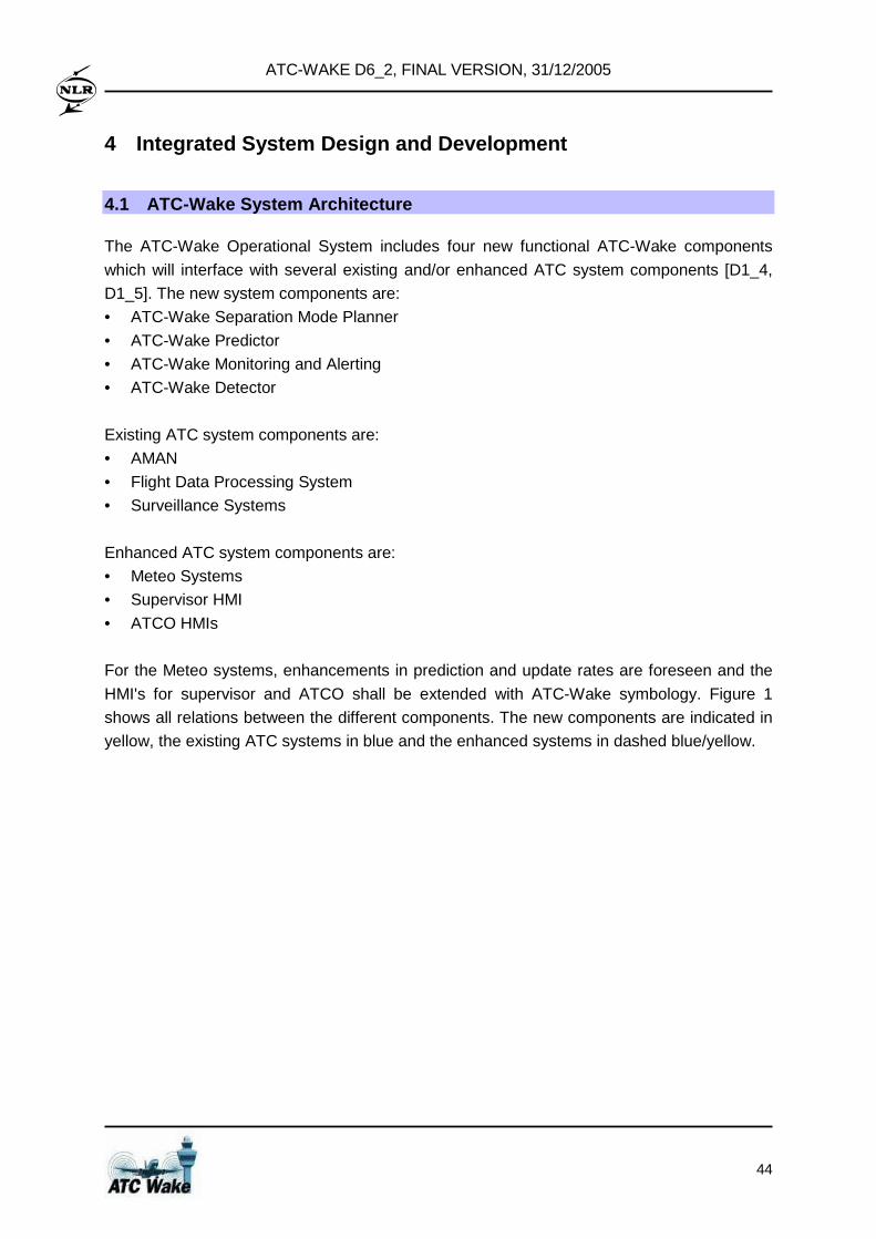
ATC-WAKE D6_2, FINAL VERSION, 31/12/2005
44
4 Integrated System Design and Development
4.1 ATC-Wake System Architecture
The ATC-Wake Operational System includes four new functional ATC-Wake components
which will interface with several existing and/or enhanced ATC system components [D1_4,
D1_5]. The new system components are:
• ATC-Wake Separation Mode Planner
• ATC-Wake Predictor
• ATC-Wake Monitoring and Alerting
• ATC-Wake Detector
Existing ATC system components are:
• AMAN
• Flight Data Processing System
• Surveillance Systems
Enhanced ATC system components are:
• Meteo Systems
• Supervisor HMI
• ATCO HMIs
For the Meteo systems, enhancements in prediction and update rates are foreseen and the
HMI's for supervisor and ATCO shall be extended with ATC-Wake symbology. Figure 1
shows all relations between the different components. The new components are indicated in
yellow, the existing ATC systems in blue and the enhanced systems in dashed blue/yellow.
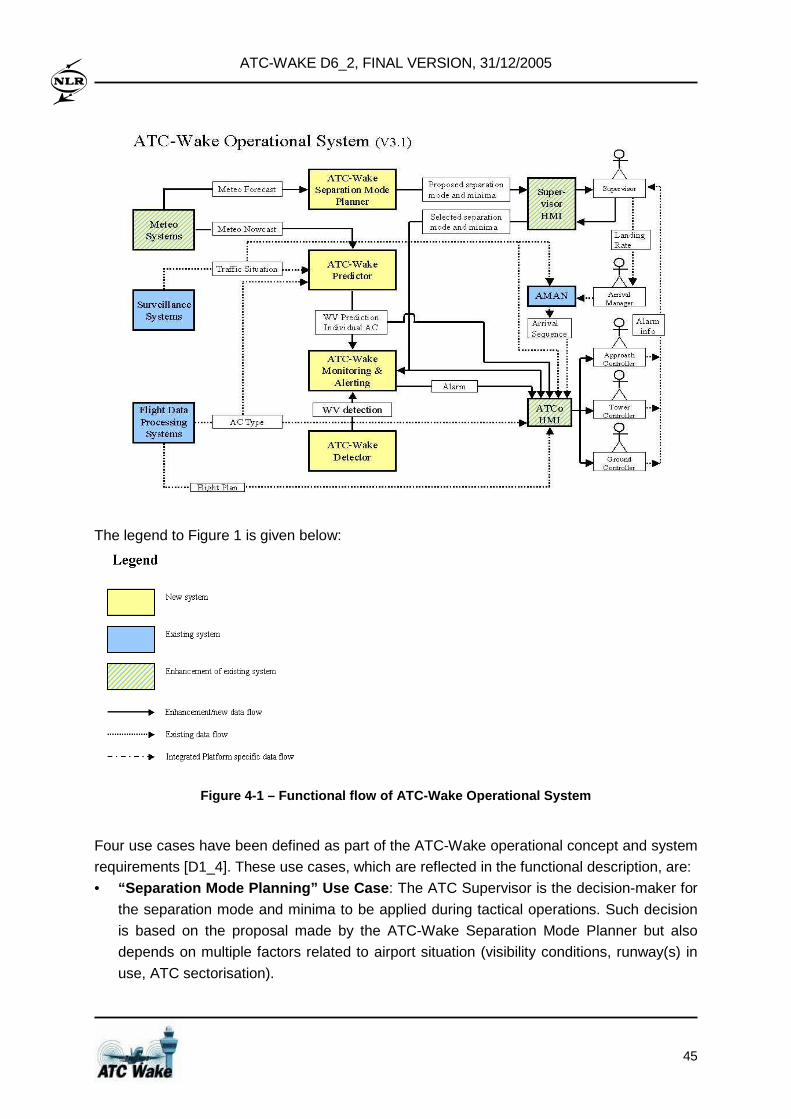
ATC-WAKE D6_2, FINAL VERSION, 31/12/2005
45
The legend to Figure 1 is given below:
Figure 4-1 – Functional flow of ATC-Wake Operationa l System
Four use cases have been defined as part of the ATC-Wake operational concept and system
requirements [D1_4]. These use cases, which are reflected in the functional description, are:
• “Separation Mode Planning” Use Case : The ATC Supervisor is the decision-maker for
the separation mode and minima to be applied during tactical operations. Such decision
is based on the proposal made by the ATC-Wake Separation Mode Planner but also
depends on multiple factors related to airport situation (visibility conditions, runway(s) in
use, ATC sectorisation).

ATC-WAKE D6_2, FINAL VERSION, 31/12/2005
46
• “Separation Mode Transition (between ICAO and ATC-W ake modes)” Use Case: This event takes place at least 40 min before the actual application of the separation
mode to the arrival or departure traffic. Information to be provided by the ATC-Wake
Separation Mode Planner are the separation mode, the separation minima, the time to
start application and the (estimated) validity of the selected mode.
• “Intermediate and Final Approach” Use Case: The Approach and Tower controllers
are provided with WV prediction information when aircraft is in the "critical area". At this
point the Approach Controller receives visual confirmation of the correct spacing between
the aircraft. The Tower Controller is in charge of the final approach phase, i.e. has to
monitor that separation is maintained along the entire glide path. Visual confirmation of
the WV “danger area” is kept up to date using meteo information and short term
predictions. Actual WV behaviour is determined by the ATC-Wake Detector and provided
to the ATC-Wake Monitoring and Alerting, in order to detect potential discrepancies
between detection and short term prediction and raise the appropriate alarm to the
concerned ATCos.
• “Departure” Use Case: The Ground Controller is in charge of preparing a departure
sequence based on the aircraft separation mode information and the departure rate
decision made by ATC Supervisor. The Tower Controller is provided with WV prediction
information (visualisation of “danger area”) when aircraft start rotating and during the
initial climb phase. Actual WV behaviour is determined by the ATC-Wake Detector and is
provided to the ATC-Wake Monitoring and Alerting, in order to detect potential
discrepancies between detection and short term prediction and to raise the appropriate
alarm to Tower ATCO.
4.2 ATC-Wake Integrated Platform overview
The ATC-Wake Integrated Platform is an essential first system development step that will
lead to installation of a new ATC decision support system at airports. It serves as a test-bed
simulation environment for the future ATC-Wake Operational System. As such, the ATC-
Wake IP is used to:
• evaluate the interoperability of the integrated system with existing ATC systems currently
used at various European airports;
• assess the safety and capacity improvements that can be obtained by local installation of
the integrated system at various European airports;
• evaluate the operational usability and acceptability of the integrated system;
• make a plan and to assess cost elements for further development, implementation and
exploitation of this platform (e.g. into the system that can be installed at European
airports).
Each of the ATC-Wake System components is represented in the IP by an existing or newly
developed tool or data base. The functional overview of the ATC-Wake IP is depicted in
Figure 4-2.
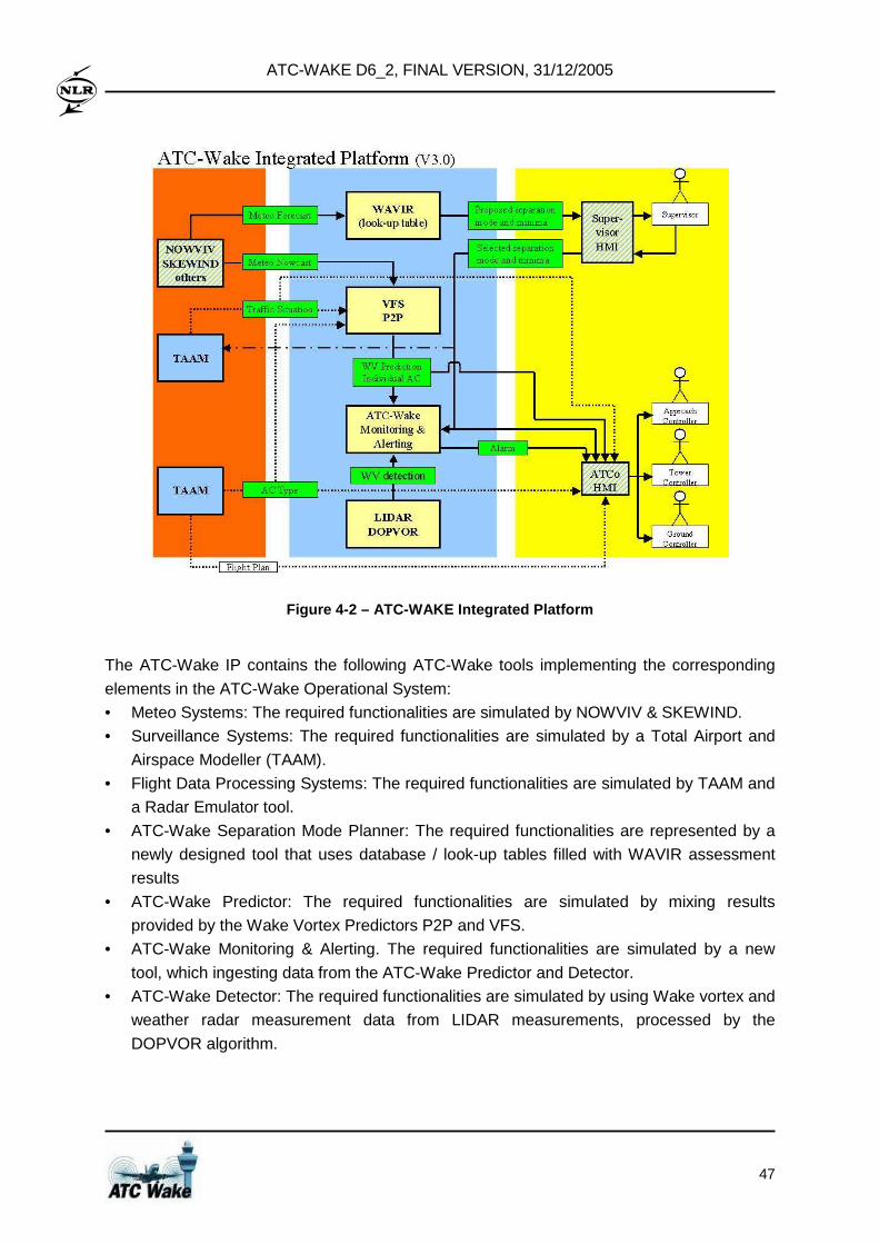
ATC-WAKE D6_2, FINAL VERSION, 31/12/2005
47
Figure 4-2 – ATC-WAKE Integrated Platform
The ATC-Wake IP contains the following ATC-Wake tools implementing the corresponding
elements in the ATC-Wake Operational System:
• Meteo Systems: The required functionalities are simulated by NOWVIV & SKEWIND.
• Surveillance Systems: The required functionalities are simulated by a Total Airport and
Airspace Modeller (TAAM).
• Flight Data Processing Systems: The required functionalities are simulated by TAAM and
a Radar Emulator tool.
• ATC-Wake Separation Mode Planner: The required functionalities are represented by a
newly designed tool that uses database / look-up tables filled with WAVIR assessment
results
• ATC-Wake Predictor: The required functionalities are simulated by mixing results
provided by the Wake Vortex Predictors P2P and VFS.
• ATC-Wake Monitoring & Alerting. The required functionalities are simulated by a new
tool, which ingesting data from the ATC-Wake Predictor and Detector.
• ATC-Wake Detector: The required functionalities are simulated by using Wake vortex and
weather radar measurement data from LIDAR measurements, processed by the
DOPVOR algorithm.
ATC-WAKE D6_2, FINAL VERSION, 31/12/2005
48
The relations between the various system components have been taken care of by defining
an Interface Requirements Specification diagram (see Figure 4-3) and developing the
required interfaces. The tools have been prepared by the consortium partners. The ATC-
Wake IP Working Environment supports the integrated and distributed use of the ATC-Wake
tools by the partners and other users.
Figure 4-3 – Interface Requirements Specification d iagram for the Integrated Platform
The ATC-Wake IP comprises a set of ATC-Wake tools integrated into an ATC-Wake IP
Working Environment. Integrated use means that the individual ATC-Wake tools proper are
wrapped and linked together in order to realise a single, coherent, and user-oriented test-bed
of the ATC IP. Distributed use means that the tools may be operated remotely, from a single
place, whereas they run on computers located with the various consortium partners’
premises. The Working Environment is realised using the SPINEware middleware which
provides and combines the notions of metacomputing (i.e., means for presenting a
distributed set of computing resources as a virtual single computer), tool wrapping (i.e.,
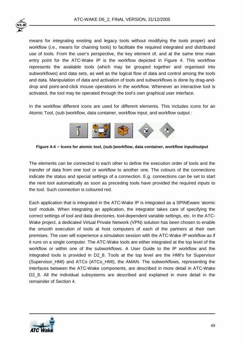
ATC-WAKE D6_2, FINAL VERSION, 31/12/2005
49
means for integrating existing and legacy tools without modifying the tools proper) and
workflow (i.e., means for chaining tools) to facilitate the required integrated and distributed
use of tools. From the user’s perspective, the key element of, and at the same time main
entry point for the ATC-Wake IP is the workflow depicted in Figure 4. This workflow
represents the available tools (which may be grouped together and organised into
subworkflows) and data sets, as well as the logical flow of data and control among the tools
and data. Manipulation of data and activation of tools and subworkflows is done by drag-and-
drop and point-and-click mouse operations in the workflow. Whenever an interactive tool is
activated, the tool may be operated through the tool’s own graphical user interface.
In the workflow different icons are used for different elements. This includes icons for an
Atomic Tool, (sub-)workflow, data container, workflow input, and workflow output :
Figure 4-4 – Icons for atomic tool, (sub-)workflow, data contain er, workflow input/output
The elements can be connected to each other to define the execution order of tools and the
transfer of data from one tool or workflow to another one. The colours of the connections
indicate the status and special settings of a connection. E.g. connections can be set to start
the next tool automatically as soon as preceding tools have provided the required inputs to
the tool. Such connection is coloured red.
Each application that is integrated in the ATC-Wake IP is integrated as a SPINEware 'atomic
tool' module. When integrating an application, the integrator takes care of specifying the
correct settings of tool and data directories, tool-dependent variable settings, etc. In the ATC-
Wake project, a dedicated Virtual Private Network (VPN) solution has been chosen to enable
the smooth execution of tools at host computers of each of the partners at their own
premises. The user will experience a simulation session with the ATC-Wake IP workflow as if
it runs on a single computer. The ATC-Wake tools are either integrated at the top level of the
workflow or within one of the subworkflows. A User Guide to the IP workflow and the
integrated tools is provided in D2_8. Tools at the top level are the HMI's for Supervisor
(Supervisor_HMI) and ATCo (ATCo_HMI), the AMAN. The subworkflows, representing the
interfaces between the ATC-Wake components, are described in more detail in ATC-Wake
D2_8. All the individual subsystems are described and explained in more detail in the
remainder of Section 4.
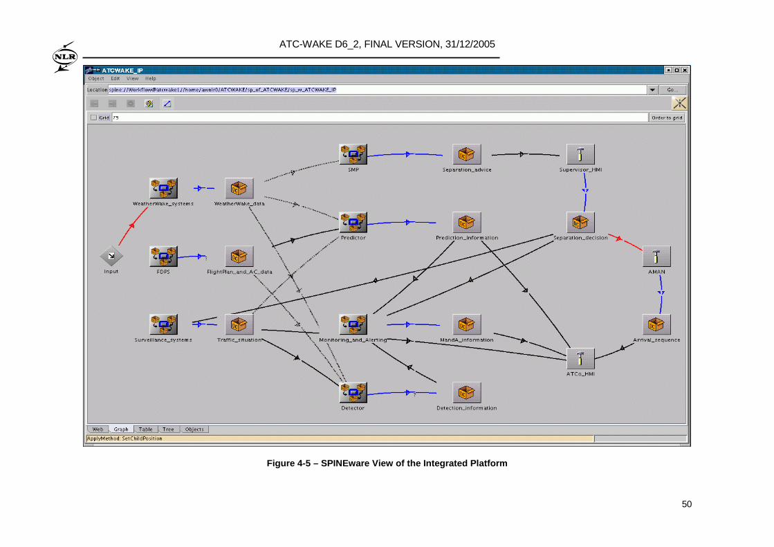
ATC-WAKE D6_2, FINAL VERSION, 31/12/2005
50
Figure 4-5 – SPINEware View of the Integrated Platf orm
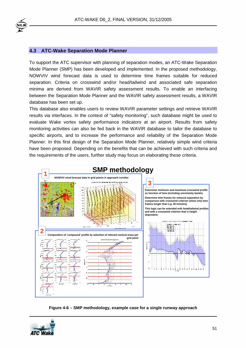
ATC-WAKE D6_2, FINAL VERSION, 31/12/2005
51
4.3 ATC-Wake Separation Mode Planner
To support the ATC supervisor with planning of separation modes, an ATC-Wake Separation
Mode Planner (SMP) has been developed and implemented. In the proposed methodology,
NOWVIV wind forecast data is used to determine time frames suitable for reduced
separation. Criteria on crosswind and/or head/tailwind and associated safe separation
minima are derived from WAVIR safety assessment results. To enable an interfacing
between the Separation Mode Planner and the WAVIR safety assessment results, a WAVIR
database has been set up.
This database also enables users to review WAVIR parameter settings and retrieve WAVIR
results via interfaces. In the context of “safety monitoring”, such database might be used to
evaluate Wake vortex safety performance indicators at an airport. Results from safety
monitoring activities can also be fed back in the WAVIR database to tailor the database to
specific airports, and to increase the performance and reliability of the Separation Mode
Planner. In this first design of the Separation Mode Planner, relatively simple wind criteria
have been proposed. Depending on the benefits that can be achieved with such criteria and
the requirements of the users, further study may focus on elaborating these criteria.
SMP methodologyNOWVIV wind forecast data in grid points in approac h corridor
Composition of ‘compound’ profile by selection of re levant vertical areas per grid point
Determine minimum and maximum crosswind profile as function of time (including uncertainty bands)
Determine time frames for reduced separation by comparison with crosswind criterion (show only time frames longer than e.g. 45 minutes).
This logic can be extended with head/tailwind profi les and with a crosswind criterion that is height dependent.
1
2
3
Figure 4-6 – SMP methodology, example case for a si ngle runway approach
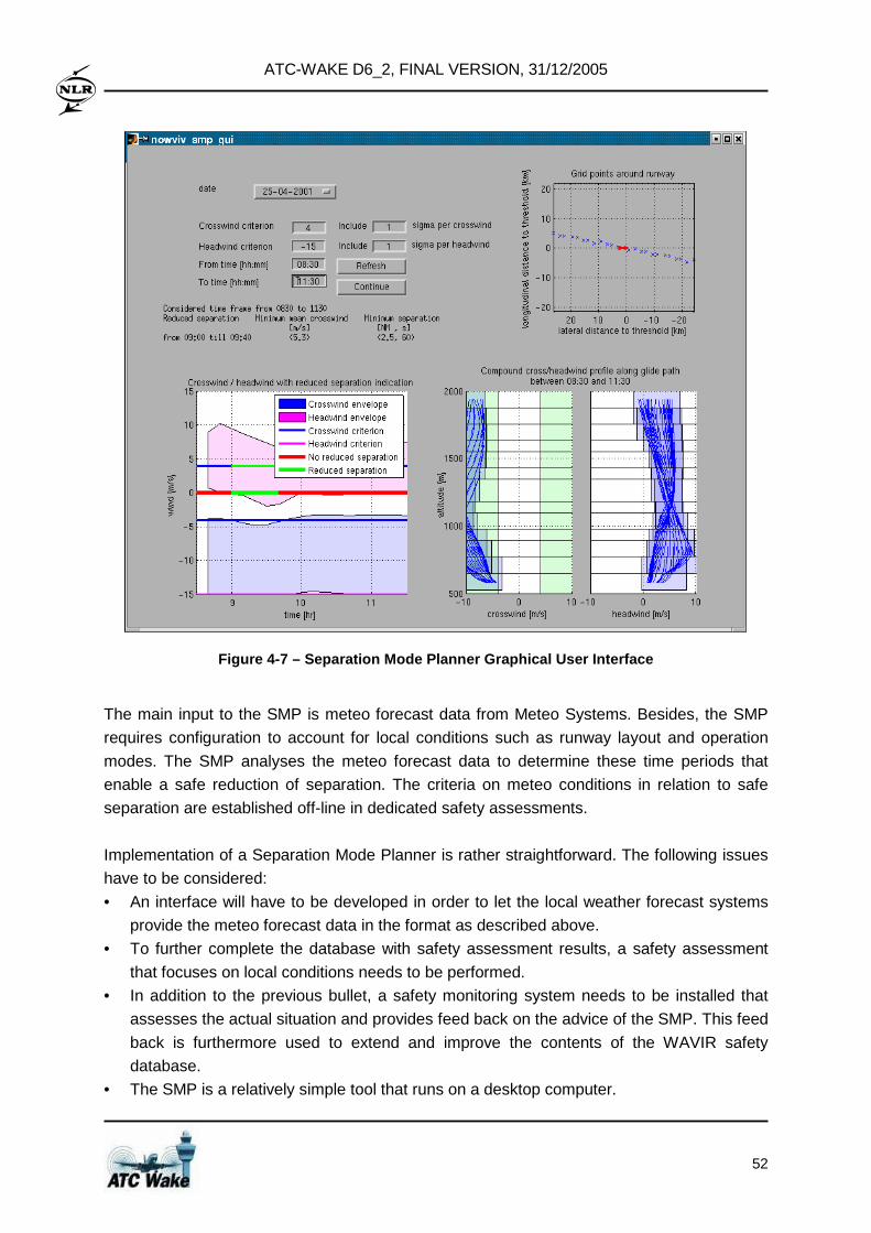
ATC-WAKE D6_2, FINAL VERSION, 31/12/2005
52
Figure 4-7 – Separation Mode Planner Graphical User Interface
The main input to the SMP is meteo forecast data from Meteo Systems. Besides, the SMP
requires configuration to account for local conditions such as runway layout and operation
modes. The SMP analyses the meteo forecast data to determine these time periods that
enable a safe reduction of separation. The criteria on meteo conditions in relation to safe
separation are established off-line in dedicated safety assessments.
Implementation of a Separation Mode Planner is rather straightforward. The following issues
have to be considered:
• An interface will have to be developed in order to let the local weather forecast systems
provide the meteo forecast data in the format as described above.
• To further complete the database with safety assessment results, a safety assessment
that focuses on local conditions needs to be performed.
• In addition to the previous bullet, a safety monitoring system needs to be installed that
assesses the actual situation and provides feed back on the advice of the SMP. This feed
back is furthermore used to extend and improve the contents of the WAVIR safety
database.
• The SMP is a relatively simple tool that runs on a desktop computer.
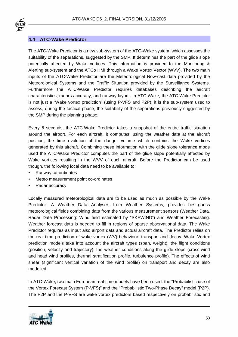
ATC-WAKE D6_2, FINAL VERSION, 31/12/2005
53
4.4 ATC-Wake Predictor
The ATC-Wake Predictor is a new sub-system of the ATC-Wake system, which assesses the
suitability of the separations, suggested by the SMP. It determines the part of the glide slope
potentially affected by Wake vortices. This information is provided to the Monitoring &
Alerting sub-system and the ATCo HMI through a Wake Vortex Vector (WVV). The two main
inputs of the ATC-Wake Predictor are the Meteorological Now-cast data provided by the
Meteorological Systems and the Traffic Situation provided by the Surveillance Systems.
Furthermore the ATC-Wake Predictor requires databases describing the aircraft
characteristics, radars accuracy, and runway layout. In ATC-Wake, the ATC-Wake Predictor
is not just a “Wake vortex prediction” (using P-VFS and P2P); it is the sub-system used to
assess, during the tactical phase, the suitability of the separations previously suggested by
the SMP during the planning phase.
Every 6 seconds, the ATC-Wake Predictor takes a snapshot of the entire traffic situation
around the airport. For each aircraft, it computes, using the weather data at the aircraft
position, the time evolution of the danger volume which contains the Wake vortices
generated by this aircraft. Combining these information with the glide slope tolerance mode
used the ATC-Wake Predictor computes the part of the glide slope potentially affected by
Wake vortices resulting in the WVV of each aircraft. Before the Predictor can be used
though, the following local data need to be available to:
• Runway co-ordinates
• Meteo measurement point co-ordinates
• Radar accuracy
Locally measured meteorological data are to be used as much as possible by the Wake
Predictor. A Weather Data Analyser, from Weather Systems, provides best-guess
meteorological fields combining data from the various measurement sensors (Weather Data,
Radar Data Processing: Wind field estimated by “SKEWIND”) and Weather Forecasting.
Weather forecast data is needed to fill in regions of sparse observational data. The Wake
Predictor requires as input also airport data and actual aircraft data. The Predictor relies on
the real-time prediction of wake vortex (WV) behaviour: transport and decay. Wake Vortex
prediction models take into account the aircraft types (span, weight), the flight conditions
(position, velocity and trajectory), the weather conditions along the glide slope (cross-wind
and head wind profiles, thermal stratification profile, turbulence profile). The effects of wind
shear (significant vertical variation of the wind profile) on transport and decay are also
modelled.
In ATC-Wake, two main European real-time models have been used: the “Probabilistic use of
the Vortex Forecast System (P-VFS)” and the “Probabilistic Two-Phase Decay” model (P2P).
The P2P and the P-VFS are wake vortex predictors based respectively on probabilistic and
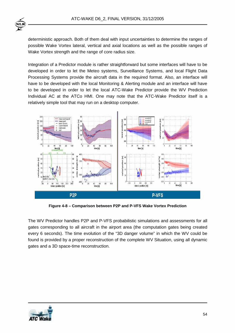
ATC-WAKE D6_2, FINAL VERSION, 31/12/2005
54
deterministic approach. Both of them deal with input uncertainties to determine the ranges of
possible Wake Vortex lateral, vertical and axial locations as well as the possible ranges of
Wake Vortex strength and the range of core radius size.
Integration of a Predictor module is rather straightforward but some interfaces will have to be
developed in order to let the Meteo systems, Surveillance Systems, and local Flight Data
Processing Systems provide the aircraft data in the required format. Also, an interface will
have to be developed with the local Monitoring & Alerting module and an interface will have
to be developed in order to let the local ATC-Wake Predictor provide the WV Prediction
Individual AC at the ATCo HMI. One may note that the ATC-Wake Predictor itself is a
relatively simple tool that may run on a desktop computer.
Figure 4-8 – Comparison between P2P and P-VFS Wake Vortex Prediction
The WV Predictor handles P2P and P-VFS probabilistic simulations and assessments for all
gates corresponding to all aircraft in the airport area (the computation gates being created
every 6 seconds). The time evolution of the “3D danger volume” in which the WV could be
found is provided by a proper reconstruction of the complete WV Situation, using all dynamic
gates and a 3D space-time reconstruction.
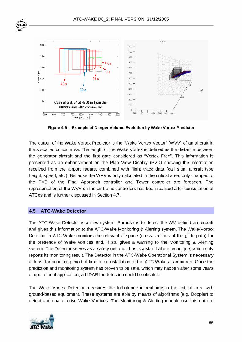
ATC-WAKE D6_2, FINAL VERSION, 31/12/2005
55
Figure 4-9 – Example of Danger Volume Evolution by Wake Vortex Predictor
The output of the Wake Vortex Predictor is the “Wake Vortex Vector” (WVV) of an aircraft in
the so-called critical area. The length of the Wake Vortex is defined as the distance between
the generator aircraft and the first gate considered as “Vortex Free”. This information is
presented as an enhancement on the Plan View Display (PVD) showing the information
received from the airport radars, combined with flight track data (call sign, aircraft type
height, speed, etc.). Because the WVV is only calculated in the critical area, only changes to
the PVD of the Final Approach controller and Tower controller are foreseen. The
representation of the WVV on the air traffic controllers has been realized after consultation of
ATCos and is further discussed in Section 4.7.
4.5 ATC-Wake Detector
The ATC-Wake Detector is a new system. Purpose is to detect the WV behind an aircraft
and gives this information to the ATC-Wake Monitoring & Alerting system. The Wake-Vortex
Detector in ATC-Wake monitors the relevant airspace (cross-sections of the glide path) for
the presence of Wake vortices and, if so, gives a warning to the Monitoring & Alerting
system. The Detector serves as a safety net and, thus is a stand-alone technique, which only
reports its monitoring result. The Detector in the ATC-Wake Operational System is necessary
at least for an initial period of time after installation of the ATC-Wake at an airport. Once the
prediction and monitoring system has proven to be safe, which may happen after some years
of operational application, a LIDAR for detection could be obsolete.
The Wake Vortex Detector measures the turbulence in real-time in the critical area with
ground-based equipment. These systems are able by means of algorithms (e.g. Doppler) to
detect and characterise Wake Vortices. The Monitoring & Alerting module use this data to
ATC-WAKE D6_2, FINAL VERSION, 31/12/2005
56
compare it with the predicted data. The Wake Vortex Detector detects for individual aircraft
the WV position, extend (“vortex vector”) and – if possible – also its strength in the pre-
defined arrival or departure area(s). Detection is performed using ground-based equipment
(pulsed LIDAR, and Doppler Radar processing called “DOPVOR”) which scan along the
critical area (ILS glide path) in pre-defined windows. No connection to airborne equipment is
assumed but detection may be complemented using airborne equipment.
Wake vortex detection by LiDAR Lidars are able to detect and monitor Wake Vortices in real time. Since Lidar is a fair weather
tool (it require a certain amount of visibility), it may be complemented by Radar techniques to
detect Wake Vortices. Ideally the whole glide path should be monitored for Wakes while the
focus should be on the Wake Vortex detection close to the surface where a Wake Vortex
encounter may be most critical. During the two measurement campaigns WakeOP and
WakeToul, Wake Vortices were scanned perpendicular to the flight path in order to
characterize the strength and position of the Wake Vortex. The 2µm pulsed Lidar system
also provides detailed information on the wind profile and, as a further product, the turbulent
state of the atmosphere. Operationally, such a Lidar system is used at Hongkong airport to
detect clear air turbulence along the glide path (however, not the whole glide path can be
covered by this system; the range is approximately 8.5 km).
Figure 4-10 – Example of Lidar scan result for Wake Vortex Monitoring
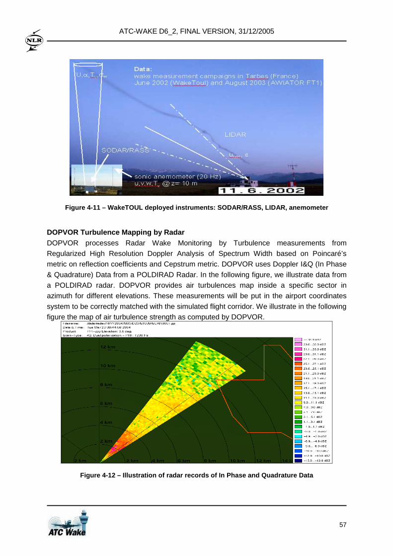
ATC-WAKE D6_2, FINAL VERSION, 31/12/2005
57
Figure 4-11 – WakeTOUL deployed instruments: SODAR/ RASS, LIDAR, anemometer
DOPVOR Turbulence Mapping by Radar DOPVOR processes Radar Wake Monitoring by Turbulence measurements from
Regularized High Resolution Doppler Analysis of Spectrum Width based on Poincaré’s
metric on reflection coefficients and Cepstrum metric. DOPVOR uses Doppler I&Q (In Phase
& Quadrature) Data from a POLDIRAD Radar. In the following figure, we illustrate data from
a POLDIRAD radar. DOPVOR provides air turbulences map inside a specific sector in
azimuth for different elevations. These measurements will be put in the airport coordinates
system to be correctly matched with the simulated flight corridor. We illustrate in the following
figure the map of air turbulence strength as computed by DOPVOR.
Figure 4-12 – Illustration of radar records of In P hase and Quadrature Data
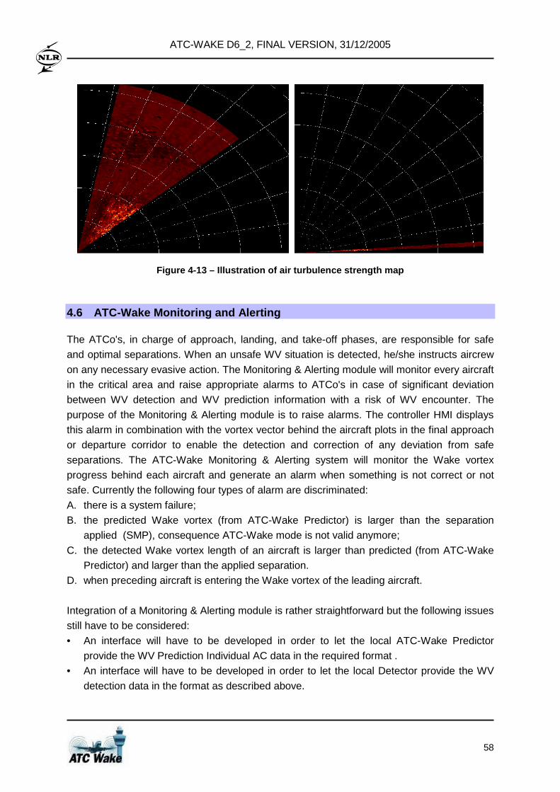
ATC-WAKE D6_2, FINAL VERSION, 31/12/2005
58
Figure 4-13 – Illustration of air turbulence streng th map
4.6 ATC-Wake Monitoring and Alerting
The ATCo's, in charge of approach, landing, and take-off phases, are responsible for safe
and optimal separations. When an unsafe WV situation is detected, he/she instructs aircrew
on any necessary evasive action. The Monitoring & Alerting module will monitor every aircraft
in the critical area and raise appropriate alarms to ATCo's in case of significant deviation
between WV detection and WV prediction information with a risk of WV encounter. The
purpose of the Monitoring & Alerting module is to raise alarms. The controller HMI displays
this alarm in combination with the vortex vector behind the aircraft plots in the final approach
or departure corridor to enable the detection and correction of any deviation from safe
separations. The ATC-Wake Monitoring & Alerting system will monitor the Wake vortex
progress behind each aircraft and generate an alarm when something is not correct or not
safe. Currently the following four types of alarm are discriminated:
A. there is a system failure;
B. the predicted Wake vortex (from ATC-Wake Predictor) is larger than the separation
applied (SMP), consequence ATC-Wake mode is not valid anymore;
C. the detected Wake vortex length of an aircraft is larger than predicted (from ATC-Wake
Predictor) and larger than the applied separation.
D. when preceding aircraft is entering the Wake vortex of the leading aircraft.
Integration of a Monitoring & Alerting module is rather straightforward but the following issues
still have to be considered:
• An interface will have to be developed in order to let the local ATC-Wake Predictor
provide the WV Prediction Individual AC data in the required format .
• An interface will have to be developed in order to let the local Detector provide the WV
detection data in the format as described above.
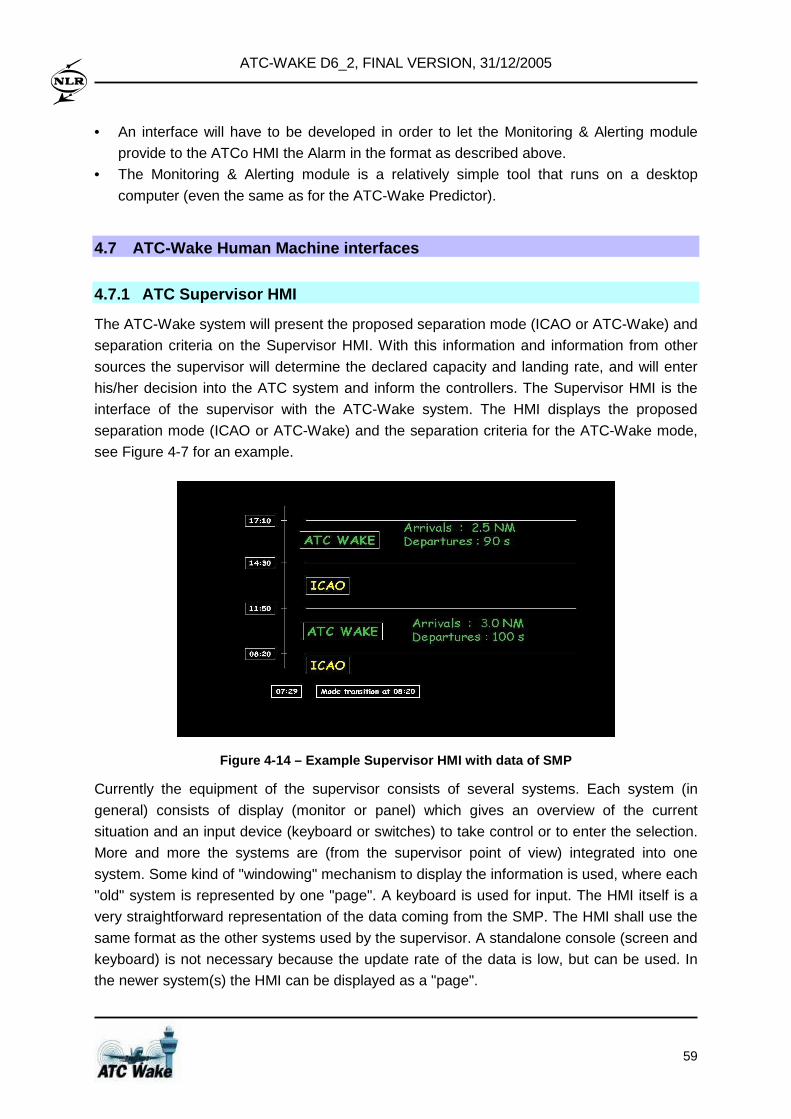
ATC-WAKE D6_2, FINAL VERSION, 31/12/2005
59
• An interface will have to be developed in order to let the Monitoring & Alerting module
provide to the ATCo HMI the Alarm in the format as described above.
• The Monitoring & Alerting module is a relatively simple tool that runs on a desktop
computer (even the same as for the ATC-Wake Predictor).
4.7 ATC-Wake Human Machine interfaces
4.7.1 ATC Supervisor HMI
The ATC-Wake system will present the proposed separation mode (ICAO or ATC-Wake) and
separation criteria on the Supervisor HMI. With this information and information from other
sources the supervisor will determine the declared capacity and landing rate, and will enter
his/her decision into the ATC system and inform the controllers. The Supervisor HMI is the
interface of the supervisor with the ATC-Wake system. The HMI displays the proposed
separation mode (ICAO or ATC-Wake) and the separation criteria for the ATC-Wake mode,
see Figure 4-7 for an example.
Figure 4-14 – Example Supervisor HMI with data of S MP
Currently the equipment of the supervisor consists of several systems. Each system (in
general) consists of display (monitor or panel) which gives an overview of the current
situation and an input device (keyboard or switches) to take control or to enter the selection.
More and more the systems are (from the supervisor point of view) integrated into one
system. Some kind of "windowing" mechanism to display the information is used, where each
"old" system is represented by one "page". A keyboard is used for input. The HMI itself is a
very straightforward representation of the data coming from the SMP. The HMI shall use the
same format as the other systems used by the supervisor. A standalone console (screen and
keyboard) is not necessary because the update rate of the data is low, but can be used. In
the newer system(s) the HMI can be displayed as a "page".
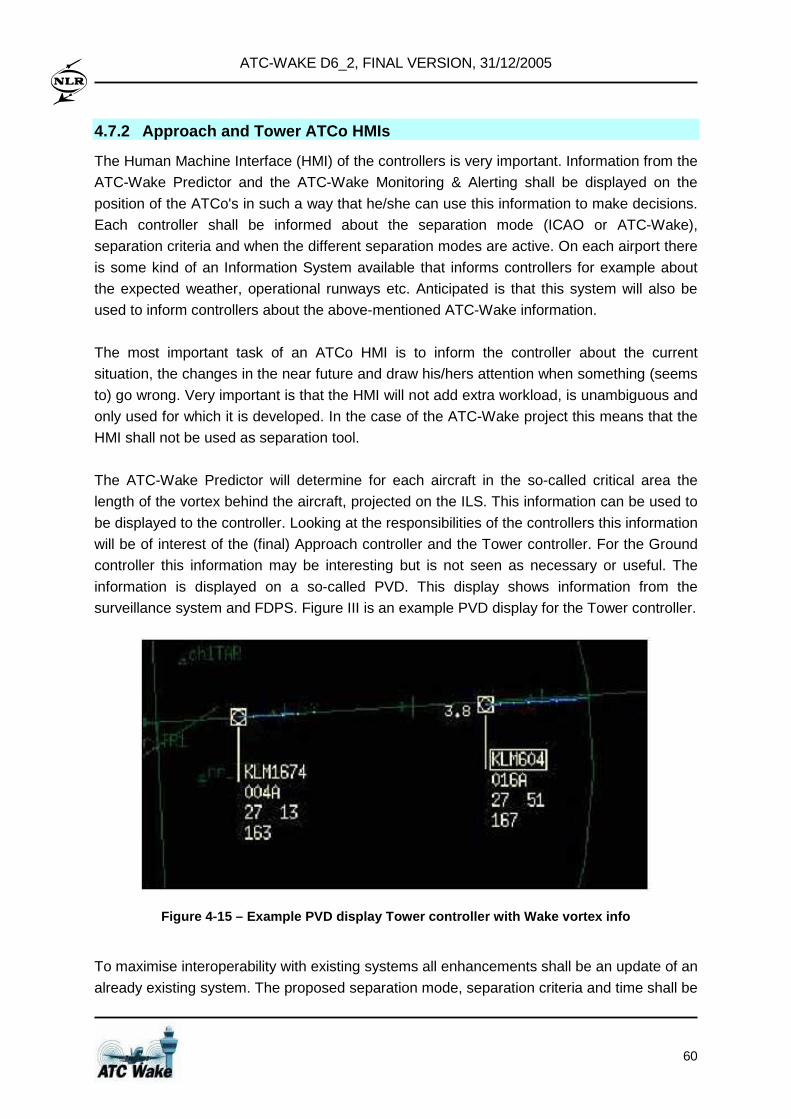
ATC-WAKE D6_2, FINAL VERSION, 31/12/2005
60
4.7.2 Approach and Tower ATCo HMIs
The Human Machine Interface (HMI) of the controllers is very important. Information from the
ATC-Wake Predictor and the ATC-Wake Monitoring & Alerting shall be displayed on the
position of the ATCo's in such a way that he/she can use this information to make decisions.
Each controller shall be informed about the separation mode (ICAO or ATC-Wake),
separation criteria and when the different separation modes are active. On each airport there
is some kind of an Information System available that informs controllers for example about
the expected weather, operational runways etc. Anticipated is that this system will also be
used to inform controllers about the above-mentioned ATC-Wake information.
The most important task of an ATCo HMI is to inform the controller about the current
situation, the changes in the near future and draw his/hers attention when something (seems
to) go wrong. Very important is that the HMI will not add extra workload, is unambiguous and
only used for which it is developed. In the case of the ATC-Wake project this means that the
HMI shall not be used as separation tool.
The ATC-Wake Predictor will determine for each aircraft in the so-called critical area the
length of the vortex behind the aircraft, projected on the ILS. This information can be used to
be displayed to the controller. Looking at the responsibilities of the controllers this information
will be of interest of the (final) Approach controller and the Tower controller. For the Ground
controller this information may be interesting but is not seen as necessary or useful. The
information is displayed on a so-called PVD. This display shows information from the
surveillance system and FDPS. Figure III is an example PVD display for the Tower controller.
Figure 4-15 – Example PVD display Tower controller with Wake vortex info
To maximise interoperability with existing systems all enhancements shall be an update of an
already existing system. The proposed separation mode, separation criteria and time shall be
ATC-WAKE D6_2, FINAL VERSION, 31/12/2005
61
presented as an extension on the Information System already available to the ATCo for
weather information and operational runways. For the Approach and Tower controller the
Wake Vortex Vector and distance to preceding aircraft shall be displayed on their PVD
according to the format in use. The Approach and Tower controller shall have the option to
turn the WV vector on or off. The surveillance system delivers a track-id for each track. The
ATC-Wake Predictor shall add the variable Wake vortex vector length to this track-id when it
is in the critical area. The software that drives the PVD will use this information to draw the
vector behind the aircraft. The same software shall calculate the slant range to the leading
aircraft and present this information in the micro-label. Also the ATC-Wake Monitoring &
Alerting system shall use the track-id to identify the aircraft involved and the corresponding
alarm, and send this information to the PVD software.
The system failure (alarm A) shall be handled according the common procedures at an
airport in case of a system failure. Currently it is not clear how to handle alarm type B. The
HMI shall use the same format as the other systems used by the ATCo. Only changes of the
Approach and Tower controller are foreseen.
4.8 Evaluation of Integrated System Design and Deve lopment
Following the definition of the Operational Concept and System Requirements, WP2 on
System Design and Evaluation has established an Integrated Platform as key intermediate
step before the ATC-Wake system can be installed locally at an airport.
The ATC-Wake Operational System comprises four new components, which interface with
several existing and/or enhanced ATC systems. New ATC-Wake components, together
constituting the Separation Advisory System (SAS), are:
• ATC-Wake Separation Mode Planner
• ATC-Wake Predictor
• ATC-Wake Monitoring and Alerting
• ATC-Wake Detector.
These components have been integrated successfully in the Integrated Platform, and it has
been shown that the functional data flow defined in WP1 on System Requirements for all
ATC-Wake Use Cases (Separation Mode Planning, Transition Phase, Approach Phase, and
Departure Phase) can be realized in an Operational ATC System.
The technical feasibility of the ATC-Wake system has been evaluated by experimental
simulations with the Integrated Platform. It has been shown that the functional integration of
the components is successful and it will be technically feasible to integrate wake vortex
prediction/detection information into existing ATC systems.
ATC-WAKE D6_2, FINAL VERSION, 31/12/2005
62
Air Traffic Controller Human Machine Interfaces have been designed, specified, and
tested successfully through two real-time simulation experiments with nine active controllers
from five European countries. It has been shown that these HMIs are compliant with the
HMIs currently used at key European airports (CdG and Schiphol).
Nevertheless, it should be mentioned that the Software Integration itself appeared to be
much more difficult than anticipated. Furthermore, there are still some key issues that will need to be addressed in more detail before the ATC-Wake system can be installed locally at an airport :
• The ATC-Wake Integrated Platform has been established using SPINEware middle-ware
technology, enabling distributed use of the ATC-Wake components prepared by the
consortium partners and running remotely at different sites. Next step will be to install all
systems together at a single site, and to demonstrate its use in real-time.
• The systems available for use as part of the ATC-Wake Detector (e.g. LiDAR and
SODAR systems) meet certain performance requirements. It is not completely clear
whether their accuracy, integrity, and reliability will be sufficient in all weather conditions.
Their complementary use should be better understood (see Section 7).
• The quality of the meteorological forecast (and now-casting) systems might need to be
enhanced allowing frequent updates of the information provided to the ATC-Wake
Separation Mode Planner and the ATC-Wake Predictor.
Finally, it shall be mentioned that the proof of technical feasibility itself is not sufficient to
draw a definite conclusion about the future use of ATC-Wake. Next steps will be to assess
the potential safety and capacity improvements (in Section 5) and the operational feasibility
(including interoperability with existing ATC-systems and usability and acceptability by the
future users (air traffic controllers and pilots) (in Section 6). A technological implementation
plan for IP exploitation is summarized in Section 7.
ATC-WAKE D6_2, FINAL VERSION, 31/12/2005
63
5 Safety and capacity analysis
5.1 Objectives
The overall objective of WP3 is to evaluate and quantify possible safety and capacity
improvements when using the ATC-Wake system. Safe and appropriate separation minima
are determined for single runways (approaches, departures, mixed mode operations) and
closely spaced parallel runways. A variety of combinations of leader and follower aircraft,
under different weather and operational conditions, will be evaluated. Such safety and
capacity analysis will be executed for the situation when using this integrated system in
combination with – and also without – instrumentation for on-board Wake vortex detection
warning and avoidance system (from I-Wake). A comparison with S-Wake results for single
runway approaches under current practice flight regulations shows the safety and capacity
benefits of the integrated system (developed in ATC-Wake) and of the on-board
instrumentation (developed in I-Wake).
This work package comprises the following objectives / activities:
• The definition of risk requirements and capacity aims;
• The execution of a qualitative safety assessment of the ATC-Wake operational concept
for different runway configurations;
• The development of a mathematical model for the behaviour of humans (controllers,
pilots) working with new Wake vortex avoidance systems;
• The extension of an existing Wake vortex induced risk model and the associated safety
and capacity analysis tool (evolving from S-Wake);
• The development and implementation of a Separation Mode Planner;
• The execution of a quantitative safety assessment (through fast-time simulations) of
different aircraft operations on various runway configurations);
• The validation of the safety assessment;
• The evaluation of safe separation distances and capacity.
5.2 Approach
The overall approach taken is to start with the derivation of capacity aims, using a series of
analytical tools and simulation platform developed by EUROCONTROL for providing
performance predictions for the future ATM system. Introducing and/or planning changes to
the ATM system cannot be done without showing that minimum safety requirements will be
satisfied. In this respect, the wake vortex risk requirements used for the ATC-Wake safety
assessments will be derived from (i.e. aim to satisfy) the ESARR 4 requirements posed by
the EUROCONTROL’s SRC.
ATC-WAKE D6_2, FINAL VERSION, 31/12/2005
64
The ATC-Wake safety assessment will be performed in two steps. The first step consists of a
qualitative safety assessment, so as to identify the hazards and safety bottlenecks
associated with the proposed operation. This allows for an improvement of the ATC-Wake
concept, which will then be analysed quantitatively through the use of the NLR Wake Vortex
Induced Risk assessment (WAVIR) methodology and toolset. This second step includes
estimation of the newly proposed ATC-Wake (reduced) separation minima under favourable
operational and weather conditions. Evaluation of Wake vortex separation distances have
been conducted using 3 approaches:
(1) Experimental flight test data,
(2) Historic operational data, and
(3) Analytical models.
As the ATC-Wake system and operation is still in the design phase, this study follows the
third approach. The intention is to build sufficient safety confidence, enabling the decision
makers to decide on operational testing and implementation.
5.3 Determining Wake vortex separation standards
Prior to the introduction of large wide-body jets, Wake vortex upsets or turbulence
encounters by a trailing aircraft were considered to be “prop-wash” or “jet wash” and not
considered a flight hazard. The introduction of large wide-body turbojet aircraft with
increased weight and wingspan in the late 1960’s changed this perception and initiated the
detailed study of Wake vortices and their impact on trailing aircraft. In mid 1969 a series of
flight test experiments were conducted by Boeing and the FAA to generate detailed
information on the Wake vortex phenomenon. By using smoke towers and probing aircraft,
the Wake vortices of a B747 and B707-320C were characterized.
This data provided the basis for Wake vortex separation rules adopted by ICAO/FAA:
• VFR rules – following aircraft remain above of the flight path of the leading aircraft
• IFR rules – minimum radar-controlled Wake separation distances were established for
the following aircraft based on the weight of the lead and follow aircraft
Although under IFR rules aircraft were categorized by weight, the data from these studies
identified that a more technically correct way to establish categories of aircraft is by wingspan
of the trailing aircraft. This was considered impractical to implement and was dropped in
favour of categorization by weight. With a few exceptions, weight exhibits relatively good
correlation with wingspan.
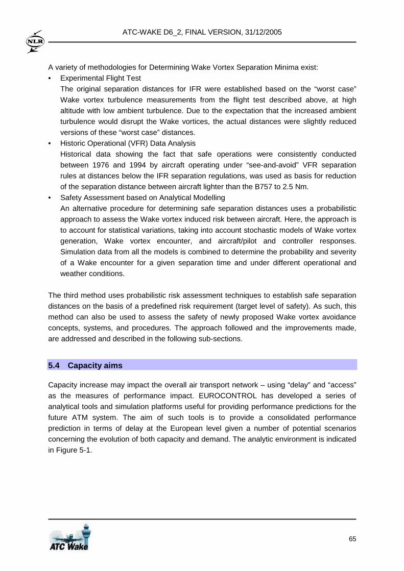
ATC-WAKE D6_2, FINAL VERSION, 31/12/2005
65
A variety of methodologies for Determining Wake Vortex Separation Minima exist:
• Experimental Flight Test
The original separation distances for IFR were established based on the “worst case”
Wake vortex turbulence measurements from the flight test described above, at high
altitude with low ambient turbulence. Due to the expectation that the increased ambient
turbulence would disrupt the Wake vortices, the actual distances were slightly reduced
versions of these “worst case” distances.
• Historic Operational (VFR) Data Analysis
Historical data showing the fact that safe operations were consistently conducted
between 1976 and 1994 by aircraft operating under “see-and-avoid” VFR separation
rules at distances below the IFR separation regulations, was used as basis for reduction
of the separation distance between aircraft lighter than the B757 to 2.5 Nm.
• Safety Assessment based on Analytical Modelling
An alternative procedure for determining safe separation distances uses a probabilistic
approach to assess the Wake vortex induced risk between aircraft. Here, the approach is
to account for statistical variations, taking into account stochastic models of Wake vortex
generation, Wake vortex encounter, and aircraft/pilot and controller responses.
Simulation data from all the models is combined to determine the probability and severity
of a Wake encounter for a given separation time and under different operational and
weather conditions.
The third method uses probabilistic risk assessment techniques to establish safe separation
distances on the basis of a predefined risk requirement (target level of safety). As such, this
method can also be used to assess the safety of newly proposed Wake vortex avoidance
concepts, systems, and procedures. The approach followed and the improvements made,
are addressed and described in the following sub-sections.
5.4 Capacity aims
Capacity increase may impact the overall air transport network – using “delay” and “access”
as the measures of performance impact. EUROCONTROL has developed a series of
analytical tools and simulation platforms useful for providing performance predictions for the
future ATM system. The aim of such tools is to provide a consolidated performance
prediction in terms of delay at the European level given a number of potential scenarios
concerning the evolution of both capacity and demand. The analytic environment is indicated
in Figure 5-1.
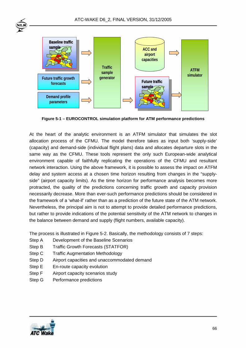
ATC-WAKE D6_2, FINAL VERSION, 31/12/2005
66
Baseline traffic sample
Future traffic growth forecasts
Demand profile parameters
Traffic sample
generatorFuture traffic sample
ACC and airport
capacities
ATFM simulator
Baseline traffic sampleBaseline traffic sampleBaseline traffic sample
Future traffic growth forecasts
Demand profile parameters
Traffic sample
generatorFuture traffic sampleFuture traffic sampleFuture traffic sample
ACC and airport
capacities
ATFM simulator
Figure 5-1 – EUROCONTROL simulation platform for AT M performance predictions
At the heart of the analytic environment is an ATFM simulator that simulates the slot
allocation process of the CFMU. The model therefore takes as input both ‘supply-side’
(capacity) and demand-side (individual flight plans) data and allocates departure slots in the
same way as the CFMU. These tools represent the only such European-wide analytical
environment capable of faithfully replicating the operations of the CFMU and resultant
network interaction. Using the above framework, it is possible to assess the impact on ATFM
delay and system access at a chosen time horizon resulting from changes in the “supply-
side” (airport capacity limits). As the time horizon for performance analysis becomes more
protracted, the quality of the predictions concerning traffic growth and capacity provision
necessarily decrease. More than ever-such performance predictions should be considered in
the framework of a ‘what-if’ rather than as a prediction of the future state of the ATM network.
Nevertheless, the principal aim is not to attempt to provide detailed performance predictions,
but rather to provide indications of the potential sensitivity of the ATM network to changes in
the balance between demand and supply (flight numbers, available capacity).
The process is illustrated in Figure 5-2. Basically, the methodology consists of 7 steps:
Step A Development of the Baseline Scenarios
Step B Traffic Growth Forecasts (STATFOR)
Step C Traffic Augmentation Methodology
Step D Airport capacities and unaccommodated demand
Step E En-route capacity evolution
Step F Airport capacity scenarios study
Step G Performance predictions
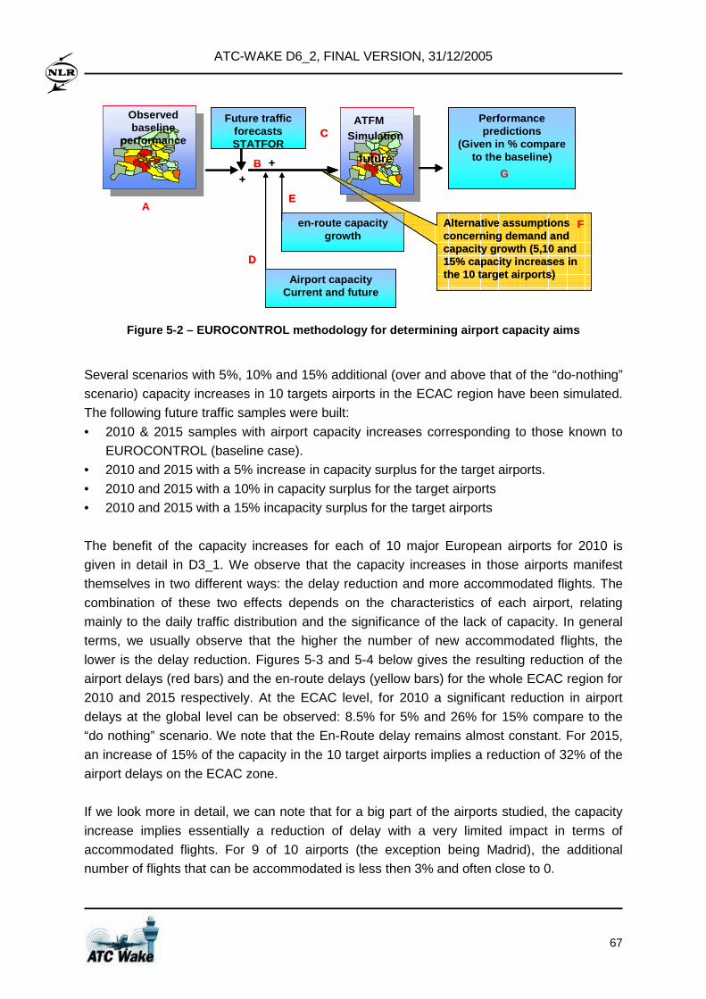
ATC-WAKE D6_2, FINAL VERSION, 31/12/2005
67
+
+
Observed baseline
performance
ATFMSimulation
2005future
en-route capacity growth
Future traffic forecastsSTATFOR
Performance predictions
(Given in % compare to the baseline)
Alternative assumptions concerning demand and capacity growth (5,10 and 15% capacity increases in the 10 target airports)
A
B
C
Airport capacity Current and future
D
E
G
F
+
+
Observed baseline
performance
ATFMSimulation
2005future
ATFMSimulation
2005future
en-route capacity growth
Future traffic forecastsSTATFOR
Performance predictions
(Given in % compare to the baseline)
Alternative assumptions concerning demand and capacity growth (5,10 and 15% capacity increases in the 10 target airports)
A
B
C
Airport capacity Current and future
D
E
G
F
Figure 5-2 – EUROCONTROL methodology for determinin g airport capacity aims
Several scenarios with 5%, 10% and 15% additional (over and above that of the “do-nothing”
scenario) capacity increases in 10 targets airports in the ECAC region have been simulated.
The following future traffic samples were built:
• 2010 & 2015 samples with airport capacity increases corresponding to those known to
EUROCONTROL (baseline case).
• 2010 and 2015 with a 5% increase in capacity surplus for the target airports.
• 2010 and 2015 with a 10% in capacity surplus for the target airports
• 2010 and 2015 with a 15% incapacity surplus for the target airports
The benefit of the capacity increases for each of 10 major European airports for 2010 is
given in detail in D3_1. We observe that the capacity increases in those airports manifest
themselves in two different ways: the delay reduction and more accommodated flights. The
combination of these two effects depends on the characteristics of each airport, relating
mainly to the daily traffic distribution and the significance of the lack of capacity. In general
terms, we usually observe that the higher the number of new accommodated flights, the
lower is the delay reduction. Figures 5-3 and 5-4 below gives the resulting reduction of the
airport delays (red bars) and the en-route delays (yellow bars) for the whole ECAC region for
2010 and 2015 respectively. At the ECAC level, for 2010 a significant reduction in airport
delays at the global level can be observed: 8.5% for 5% and 26% for 15% compare to the
“do nothing” scenario. We note that the En-Route delay remains almost constant. For 2015,
an increase of 15% of the capacity in the 10 target airports implies a reduction of 32% of the
airport delays on the ECAC zone.
If we look more in detail, we can note that for a big part of the airports studied, the capacity
increase implies essentially a reduction of delay with a very limited impact in terms of
accommodated flights. For 9 of 10 airports (the exception being Madrid), the additional
number of flights that can be accommodated is less then 3% and often close to 0.
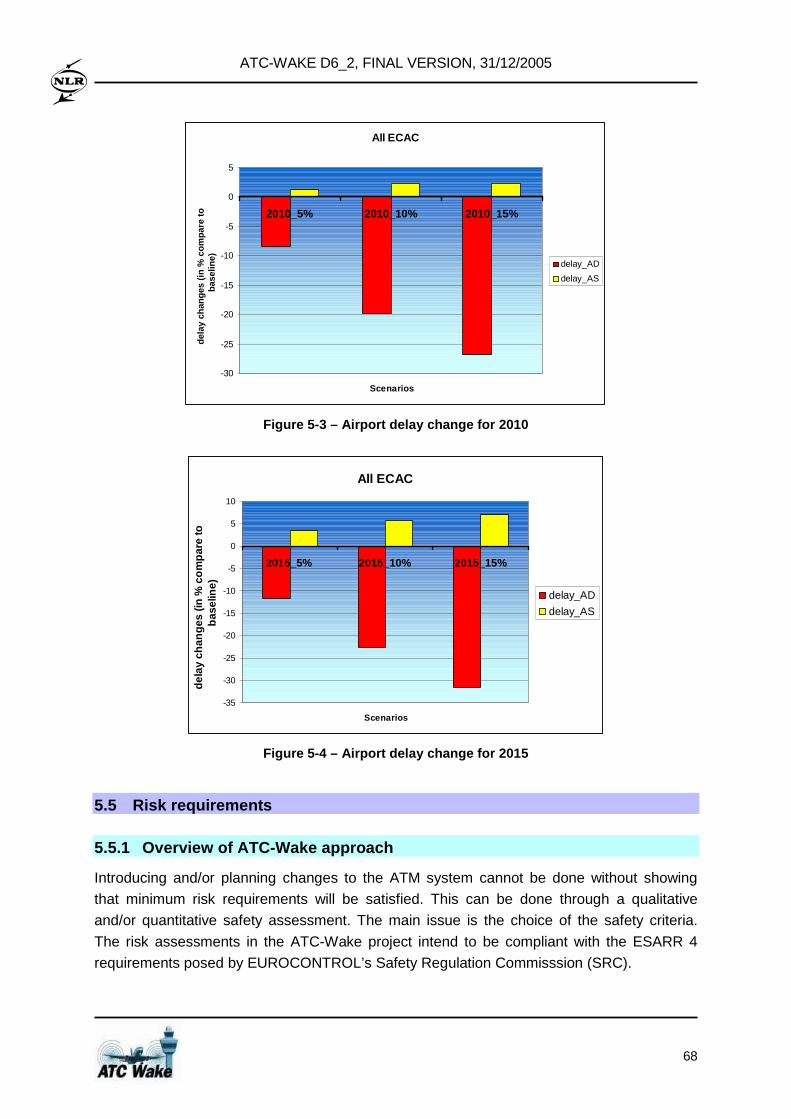
ATC-WAKE D6_2, FINAL VERSION, 31/12/2005
68
All ECAC
-30
-25
-20
-15
-10
-5
0
5
2010_5% 2010_10% 2010_15%
Scenarios
dela
y ch
ange
s (in
% c
ompa
re to
ba
selin
e) delay_AD
delay_AS
Figure 5-3 – Airport delay change for 2010
All ECAC
-35
-30
-25
-20
-15
-10
-5
0
5
10
2015_5% 2015_10% 2015_15%
Scenarios
dela
y ch
ange
s (in
% c
ompa
re to
ba
selin
e)
delay_AD
delay_AS
Figure 5-4 – Airport delay change for 2015
5.5 Risk requirements 5.5.1 Overview of ATC-Wake approach
Introducing and/or planning changes to the ATM system cannot be done without showing
that minimum risk requirements will be satisfied. This can be done through a qualitative
and/or quantitative safety assessment. The main issue is the choice of the safety criteria.
The risk assessments in the ATC-Wake project intend to be compliant with the ESARR 4
requirements posed by EUROCONTROL’s Safety Regulation Commisssion (SRC).
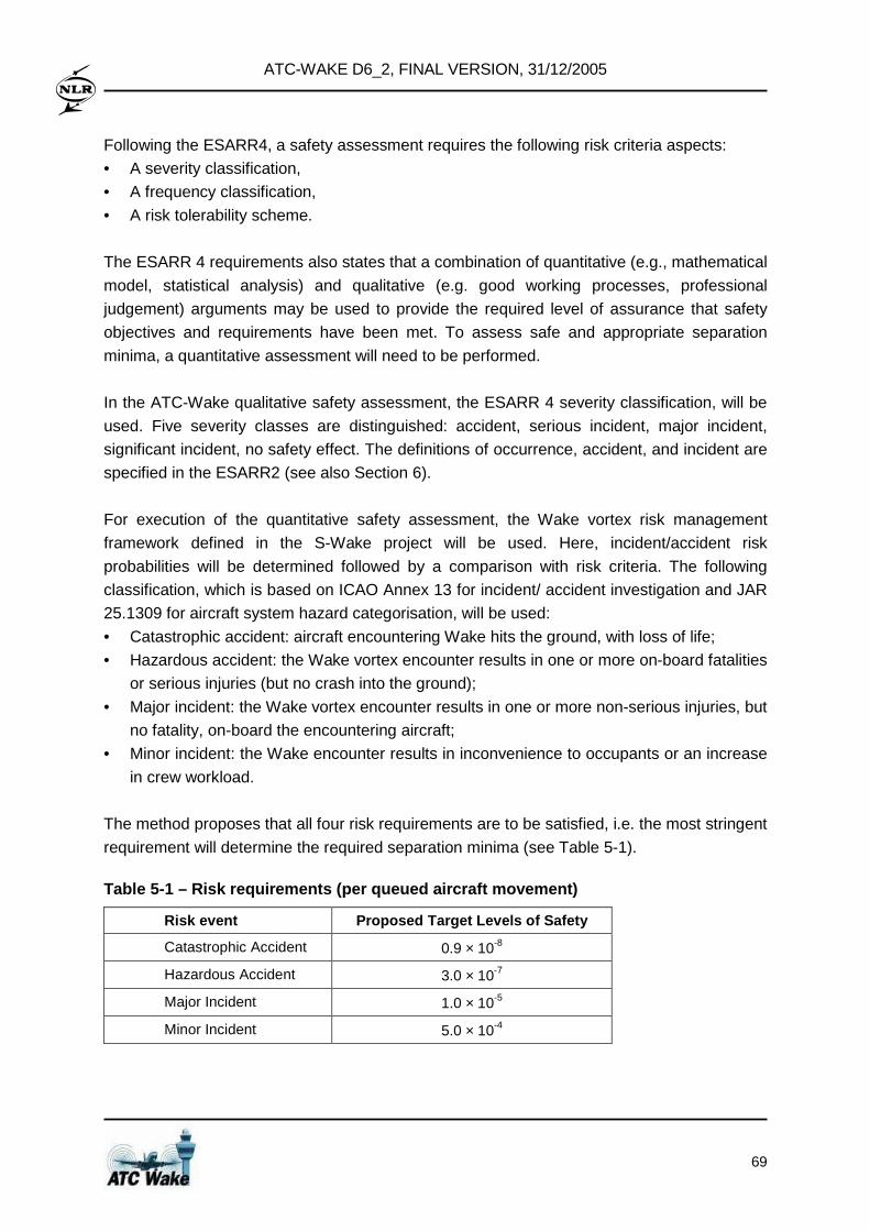
ATC-WAKE D6_2, FINAL VERSION, 31/12/2005
69
Following the ESARR4, a safety assessment requires the following risk criteria aspects:
• A severity classification,
• A frequency classification,
• A risk tolerability scheme.
The ESARR 4 requirements also states that a combination of quantitative (e.g., mathematical
model, statistical analysis) and qualitative (e.g. good working processes, professional
judgement) arguments may be used to provide the required level of assurance that safety
objectives and requirements have been met. To assess safe and appropriate separation
minima, a quantitative assessment will need to be performed.
In the ATC-Wake qualitative safety assessment, the ESARR 4 severity classification, will be
used. Five severity classes are distinguished: accident, serious incident, major incident,
significant incident, no safety effect. The definitions of occurrence, accident, and incident are
specified in the ESARR2 (see also Section 6).
For execution of the quantitative safety assessment, the Wake vortex risk management
framework defined in the S-Wake project will be used. Here, incident/accident risk
probabilities will be determined followed by a comparison with risk criteria. The following
classification, which is based on ICAO Annex 13 for incident/ accident investigation and JAR
25.1309 for aircraft system hazard categorisation, will be used:
• Catastrophic accident: aircraft encountering Wake hits the ground, with loss of life;
• Hazardous accident: the Wake vortex encounter results in one or more on-board fatalities
or serious injuries (but no crash into the ground);
• Major incident: the Wake vortex encounter results in one or more non-serious injuries, but
no fatality, on-board the encountering aircraft;
• Minor incident: the Wake encounter results in inconvenience to occupants or an increase
in crew workload.
The method proposes that all four risk requirements are to be satisfied, i.e. the most stringent
requirement will determine the required separation minima (see Table 5-1).
Table 5-1 – Risk requirements (per queued aircraft movement)
Risk event Proposed Target Levels of S afety
Catastrophic Accident 0.9 × 10⁻⁸
Hazardous Accident 3.0 × 10⁻⁷
Major Incident 1.0 × 10⁻⁵
Minor Incident 5.0 × 10⁻⁴
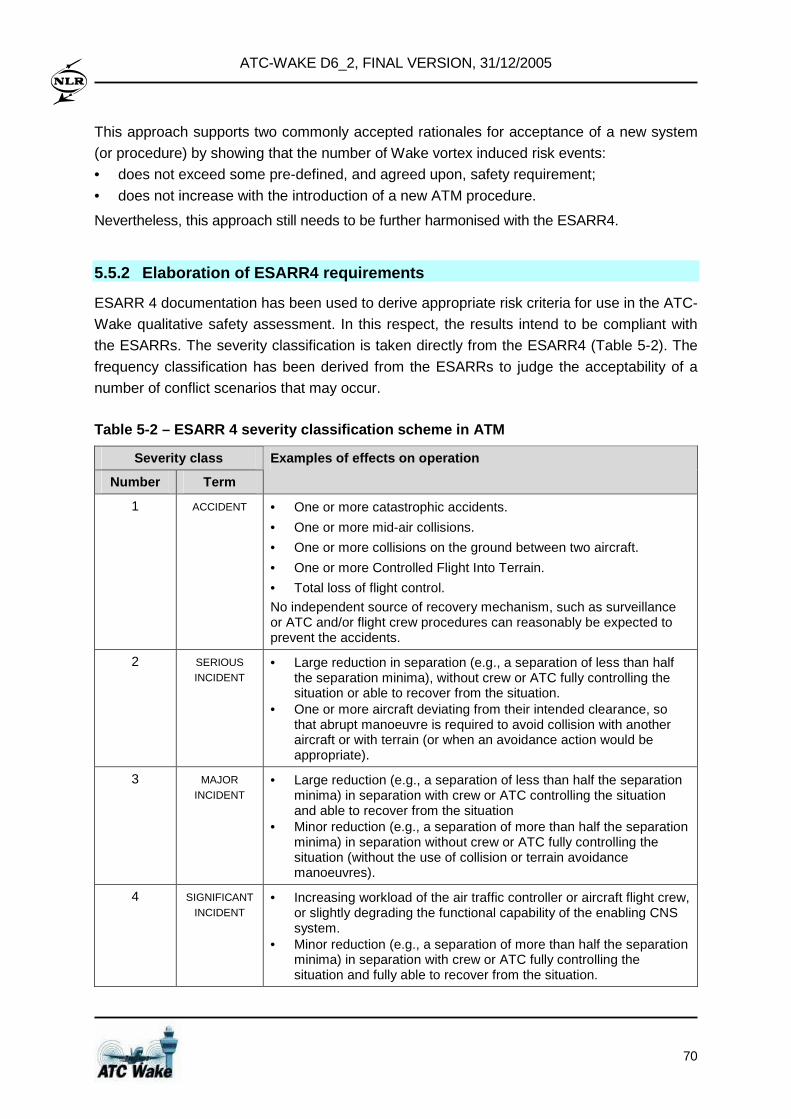
ATC-WAKE D6_2, FINAL VERSION, 31/12/2005
70
This approach supports two commonly accepted rationales for acceptance of a new system
(or procedure) by showing that the number of Wake vortex induced risk events:
• does not exceed some pre-defined, and agreed upon, safety requirement;
• does not increase with the introduction of a new ATM procedure.
Nevertheless, this approach still needs to be further harmonised with the ESARR4.
5.5.2 Elaboration of ESARR4 requirements
ESARR 4 documentation has been used to derive appropriate risk criteria for use in the ATC-
Wake qualitative safety assessment. In this respect, the results intend to be compliant with
the ESARRs. The severity classification is taken directly from the ESARR4 (Table 5-2). The
frequency classification has been derived from the ESARRs to judge the acceptability of a
number of conflict scenarios that may occur.
Table 5-2 – ESARR 4 severity classification scheme in ATM
Severity class
Number Term
Examples of effects on operation
1 ACCIDENT • One or more catastrophic accidents.
• One or more mid-air collisions.
• One or more collisions on the ground between two aircraft.
• One or more Controlled Flight Into Terrain.
• Total loss of flight control.
No independent source of recovery mechanism, such as surveillance or ATC and/or flight crew procedures can reasonably be expected to prevent the accidents.
2 SERIOUS INCIDENT
• Large reduction in separation (e.g., a separation of less than half the separation minima), without crew or ATC fully controlling the situation or able to recover from the situation.
• One or more aircraft deviating from their intended clearance, so that abrupt manoeuvre is required to avoid collision with another aircraft or with terrain (or when an avoidance action would be appropriate).
3 MAJOR INCIDENT
• Large reduction (e.g., a separation of less than half the separation minima) in separation with crew or ATC controlling the situation and able to recover from the situation
• Minor reduction (e.g., a separation of more than half the separation minima) in separation without crew or ATC fully controlling the situation (without the use of collision or terrain avoidance manoeuvres).
4 SIGNIFICANT INCIDENT
• Increasing workload of the air traffic controller or aircraft flight crew, or slightly degrading the functional capability of the enabling CNS system.
• Minor reduction (e.g., a separation of more than half the separation minima) in separation with crew or ATC fully controlling the situation and fully able to recover from the situation.
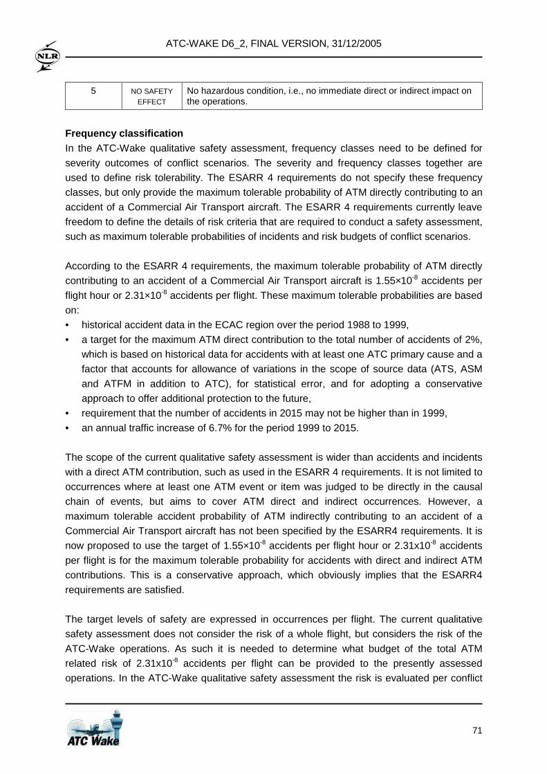
ATC-WAKE D6_2, FINAL VERSION, 31/12/2005
71
5 NO SAFETY EFFECT
No hazardous condition, i.e., no immediate direct or indirect impact on the operations.
Frequency classification In the ATC-Wake qualitative safety assessment, frequency classes need to be defined for
severity outcomes of conflict scenarios. The severity and frequency classes together are
used to define risk tolerability. The ESARR 4 requirements do not specify these frequency
classes, but only provide the maximum tolerable probability of ATM directly contributing to an
accident of a Commercial Air Transport aircraft. The ESARR 4 requirements currently leave
freedom to define the details of risk criteria that are required to conduct a safety assessment,
such as maximum tolerable probabilities of incidents and risk budgets of conflict scenarios.
According to the ESARR 4 requirements, the maximum tolerable probability of ATM directly
contributing to an accident of a Commercial Air Transport aircraft is 1.55×10⁻⁸ accidents per
flight hour or 2.31×10⁻⁸ accidents per flight. These maximum tolerable probabilities are based
on:
• historical accident data in the ECAC region over the period 1988 to 1999,
• a target for the maximum ATM direct contribution to the total number of accidents of 2%,
which is based on historical data for accidents with at least one ATC primary cause and a
factor that accounts for allowance of variations in the scope of source data (ATS, ASM
and ATFM in addition to ATC), for statistical error, and for adopting a conservative
approach to offer additional protection to the future,
• requirement that the number of accidents in 2015 may not be higher than in 1999,
• an annual traffic increase of 6.7% for the period 1999 to 2015.
The scope of the current qualitative safety assessment is wider than accidents and incidents
with a direct ATM contribution, such as used in the ESARR 4 requirements. It is not limited to
occurrences where at least one ATM event or item was judged to be directly in the causal
chain of events, but aims to cover ATM direct and indirect occurrences. However, a
maximum tolerable accident probability of ATM indirectly contributing to an accident of a
Commercial Air Transport aircraft has not been specified by the ESARR4 requirements. It is
now proposed to use the target of 1.55×10⁻⁸ accidents per flight hour or 2.31x10⁻⁸ accidents
per flight is for the maximum tolerable probability for accidents with direct and indirect ATM
contributions. This is a conservative approach, which obviously implies that the ESARR4
requirements are satisfied.
The target levels of safety are expressed in occurrences per flight. The current qualitative
safety assessment does not consider the risk of a whole flight, but considers the risk of the
ATC-Wake operations. As such it is needed to determine what budget of the total ATM
related risk of 2.31x10⁻⁸ accidents per flight can be provided to the presently assessed
operations. In the ATC-Wake qualitative safety assessment the risk is evaluated per conflict
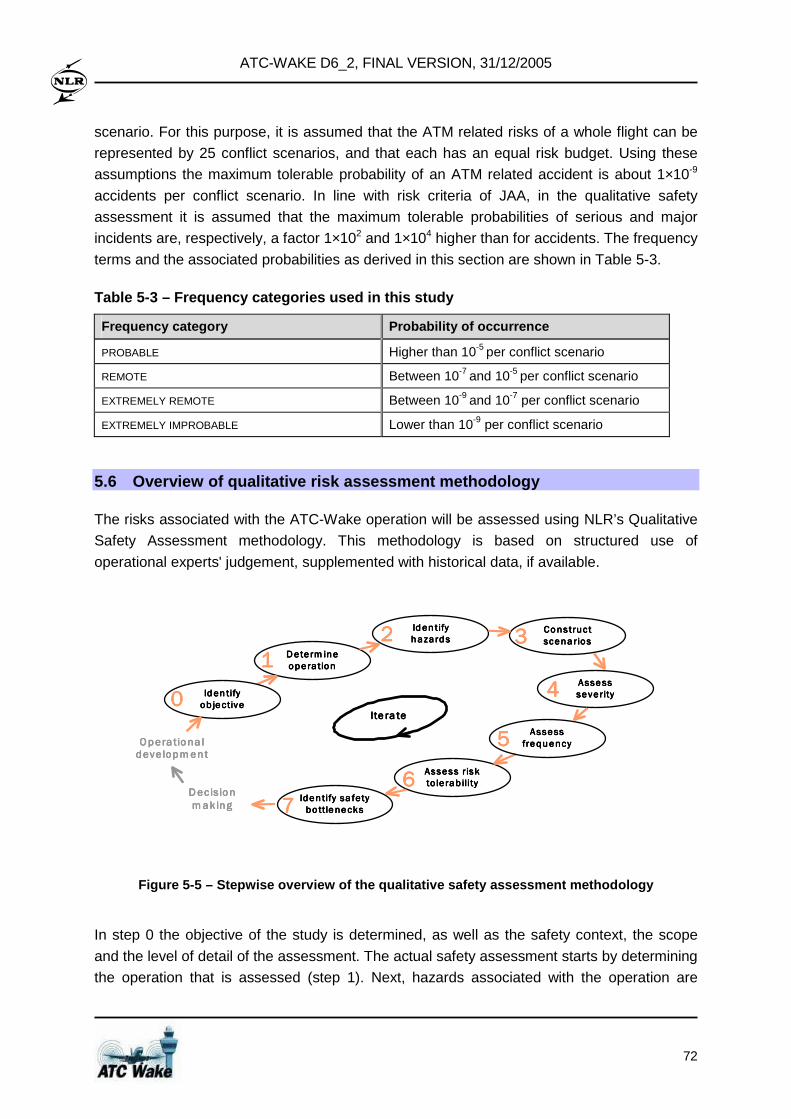
ATC-WAKE D6_2, FINAL VERSION, 31/12/2005
72
scenario. For this purpose, it is assumed that the ATM related risks of a whole flight can be
represented by 25 conflict scenarios, and that each has an equal risk budget. Using these
assumptions the maximum tolerable probability of an ATM related accident is about 1×10⁻⁹
accidents per conflict scenario. In line with risk criteria of JAA, in the qualitative safety
assessment it is assumed that the maximum tolerable probabilities of serious and major
incidents are, respectively, a factor 1×10² and 1×10⁴ higher than for accidents. The frequency
terms and the associated probabilities as derived in this section are shown in Table 5-3.
Table 5-3 – Frequency categories used in this study
Frequency category Probability of occurrence
PROBABLE Higher than 10-5 per conflict scenario
REMOTE Between 10-7 and 10-5 per conflict scenario
EXTREMELY REMOTE Between 10-9 and 10-7 per conflict scenario
EXTREMELY IMPROBABLE Lower than 10-9 per conflict scenario
5.6 Overview of qualitative risk assessment methodo logy
The risks associated with the ATC-Wake operation will be assessed using NLR’s Qualitative
Safety Assessment methodology. This methodology is based on structured use of
operational experts' judgement, supplemented with historical data, if available.
Determ ineDeterm ineDeterm ineDeterm ine
operationoperationoperationoperation1111
Assess riskAssess riskAssess riskAssess risk
to le rab ilityto le rab ilityto le rab ilityto le rab ility6666
AssessAssessAssessAssess
severityseverityseverityseverity4444
Identify sa fetyIdentify sa fetyIdentify sa fetyIdentify sa fety
bo ttlenecksbo ttlenecksbo ttlenecksbo ttlenecks7777
AssessAssessAssessAssess
frequencyfrequencyfrequencyfrequency5555
ConstructConstructConstructConstruct
scenariosscenariosscenariosscenarios3333Iden tifyIden tifyIden tifyIden tify
hazardshazardshazardshazards2222
Ite ra teIte ra teIte ra teIte ra te
Iden tifyIden tifyIden tifyIden tify
ob jectiveob jectiveob jectiveob jective0000
DecisionDecisionDecisionDecision
mak ingmak ingmak ingmak ing
Opera tiona lOpera tiona lOpera tiona lOpera tiona ldeve lopmentdeve lopmentdeve lopmentdeve lopment
Figure 5-5 – Stepwise overview of the qualitative s afety assessment methodology
In step 0 the objective of the study is determined, as well as the safety context, the scope
and the level of detail of the assessment. The actual safety assessment starts by determining
the operation that is assessed (step 1). Next, hazards associated with the operation are
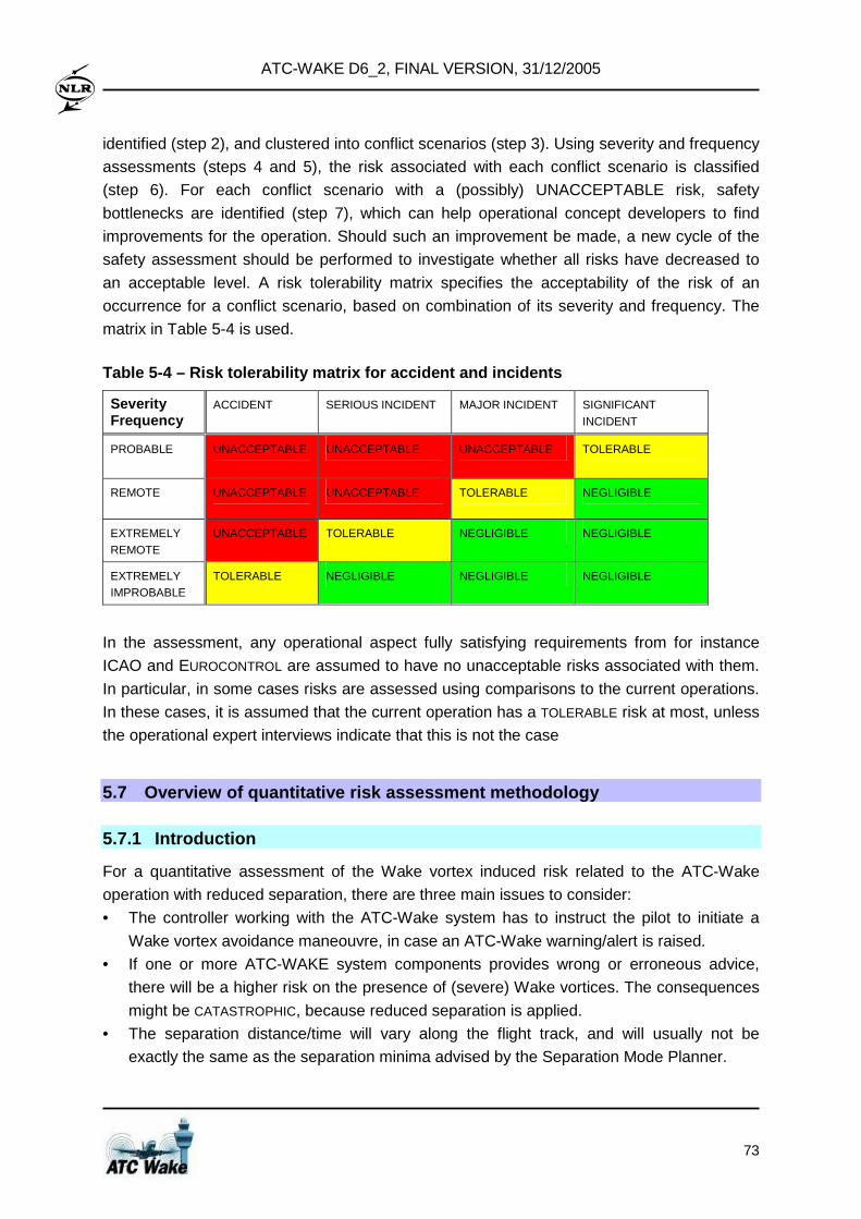
ATC-WAKE D6_2, FINAL VERSION, 31/12/2005
73
identified (step 2), and clustered into conflict scenarios (step 3). Using severity and frequency
assessments (steps 4 and 5), the risk associated with each conflict scenario is classified
(step 6). For each conflict scenario with a (possibly) UNACCEPTABLE risk, safety
bottlenecks are identified (step 7), which can help operational concept developers to find
improvements for the operation. Should such an improvement be made, a new cycle of the
safety assessment should be performed to investigate whether all risks have decreased to
an acceptable level. A risk tolerability matrix specifies the acceptability of the risk of an
occurrence for a conflict scenario, based on combination of its severity and frequency. The
matrix in Table 5-4 is used.
Table 5-4 – Risk tolerability matrix for accident a nd incidents
Severity Frequency
ACCIDENT SERIOUS INCIDENT MAJOR INCIDENT SIGNIFICANT INCIDENT
PROBABLE UNACCEPTABLE UNACCEPTABLE UNACCEPTABLE TOLERABLE
REMOTE UNACCEPTABLE UNACCEPTABLE TOLERABLE NEGLIGIBLE
EXTREMELY REMOTE
UNACCEPTABLE TOLERABLE NEGLIGIBLE NEGLIGIBLE
EXTREMELY IMPROBABLE
TOLERABLE NEGLIGIBLE NEGLIGIBLE NEGLIGIBLE
In the assessment, any operational aspect fully satisfying requirements from for instance
ICAO and EUROCONTROL are assumed to have no unacceptable risks associated with them.
In particular, in some cases risks are assessed using comparisons to the current operations.
In these cases, it is assumed that the current operation has a TOLERABLE risk at most, unless
the operational expert interviews indicate that this is not the case
5.7 Overview of quantitative risk assessment method ology 5.7.1 Introduction
For a quantitative assessment of the Wake vortex induced risk related to the ATC-Wake
operation with reduced separation, there are three main issues to consider:
• The controller working with the ATC-Wake system has to instruct the pilot to initiate a
Wake vortex avoidance maneouvre, in case an ATC-Wake warning/alert is raised.
• If one or more ATC-WAKE system components provides wrong or erroneous advice,
there will be a higher risk on the presence of (severe) Wake vortices. The consequences
might be CATASTROPHIC, because reduced separation is applied.
• The separation distance/time will vary along the flight track, and will usually not be
exactly the same as the separation minima advised by the Separation Mode Planner.
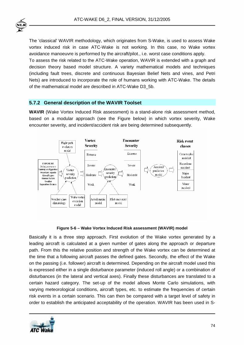
ATC-WAKE D6_2, FINAL VERSION, 31/12/2005
74
The 'classical' WAVIR methodology, which originates from S-Wake, is used to assess Wake
vortex induced risk in case ATC-Wake is not working. In this case, no Wake vortex
avoidance manoeuvre is performed by the aircraft/pilot., i.e. worst case conditions apply.
To assess the risk related to the ATC-Wake operation, WAVIR is extended with a graph and
decision theory based model structure. A variety mathematical models and techniques
(including fault trees, discrete and continuous Bayesian Belief Nets and vines, and Petri
Nets) are introduced to incorporate the role of humans working with ATC-Wake. The details
of the mathematical model are described in ATC-Wake D3_5b.
5.7.2 General description of the WAVIR Toolset
WAVIR (Wake Vortex Induced Risk assessment) is a stand-alone risk assessment method,
based on a modular approach (see the Figure below) in which vortex severity, Wake
encounter severity, and incident/accident risk are being determined subsequently.
Figure 5-6 – Wake Vortex Induced Risk assessment (W AVIR) model
Basically it is a three step approach. First evolution of the Wake vortex generated by a
leading aircraft is calculated at a given number of gates along the approach or departure
path. From this the relative position and strength of the Wake vortex can be determined at
the time that a following aircraft passes the defined gates. Secondly, the effect of the Wake
on the passing (i.e. follower) aircraft is determined. Depending on the aircraft model used this
is expressed either in a single disturbance parameter (induced roll angle) or a combination of
disturbances (in the lateral and vertical axes). Finally these disturbances are translated to a
certain hazard category. The set-up of the model allows Monte Carlo simulations, with
varying meteorological conditions, aircraft types, etc. to estimate the frequencies of certain
risk events in a certain scenario. This can then be compared with a target level of safety in
order to establish the anticipated acceptability of the operation. WAVIR has been used in S-
ATC-WAKE D6_2, FINAL VERSION, 31/12/2005
75
Wake to assess the Wake vortex safety of current practice single runway operations. In ATC-
Wake, WAVIR has been extended to cover the whole airport environment (including
departures). Here, the roles and reaction times of humans (pilots, controllers) working with
Wake vortex concepts and procedures is explicitly modelled and analysed.
5.8 Qualitative safety assessment 5.8.1 Introduction
A qualitative safety assessment has been performed to get a global overview of the risks
associated with the proposed ATC-Wake operation for single runway arrivals, single runway
departures and closely spaced parallel runway departures. Moreover, in this way safety
bottlenecks are fed back to the operation designers at an early stage, and this enables
further focussing in the safety modelling activities and quantitative safety assessment that
are also planned within this work package. In line with the ATC-Wake operation, the
assessment is restricted to the following sub-operations:
• end of cruise to final approach;
• arrivals to single runway;
• arrivals to closely spaced parallel runways; and
• departures from single runway.
The assessment has been limited to the risks air traffic participants are running, and for
which air traffic control bears responsibility. This for instance excludes risks experienced by
people living on the ground, or risks not related to ATC. The assessment did not only
concern Wake vortex risks; also other risks (as for instance collision risk) related to ATC-
Wake aspects of the operation were considered.
5.8.2 Identification of hazards and conflict scenar ios
In various brainstorming sessions with operational experts, hazards have been identified that
could occur in the considered operation. After the identification of hazards, these hazards
have been structured into conflict scenarios, which describe all relevant ways how these
hazards may lead to conflicts or worsen them. The conflict scenarios are:
I. Wake vortex encounter during departure
II. Wake vortex encounter during single runway arrival
III. Missed approach during single runway arrival
IV. Wake vortex encounter before ILS interception
V. Wake vortex encounter during arrivals on closely spaced parallel runway
VI. Missed approach during arrivals on closely spaced parallel runways
VII. Higher traffic rates in TMA, holding, sector, or on runway
VIII. Turbulence
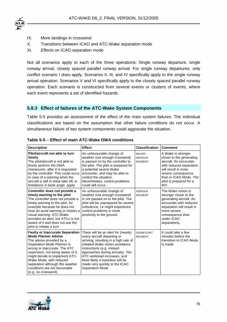
ATC-WAKE D6_2, FINAL VERSION, 31/12/2005
76
IX. More landings in crosswind
X. Transitions between ICAO and ATC-Wake separation mode
XI. Effects on ICAO separation mode
Not all scenarios apply to each of the three operations: Single runway departure, single
runway arrival, closely spaced parallel runway arrival. For single runway departures, only
conflict scenario I does apply. Scenarios II, III, and IV specifically apply to the single runway
arrival operation. Scenarios V and VI specifically apply to the closely spaced parallel runway
operation. Each scenario is constructed from several events or clusters of events, where
each event represents a set of identified hazards.
5.8.3 Effect of failures of the ATC-Wake System Com ponents
Table 5-5 provides an assessment of the effect of the main system failures. The individual
classifications are based on the assumption that other failure conditions do not occur. A
simultaneous failure of two system components could aggravate the situation.
Table 5-5 – Effect of main ATC-Wake DWA conditions
Description Effect Classification Comment
Pilot/aircraft not able to turn timely The pilot/aircraft is not able to timely perform the DWA maneouvre, after it is requested by the controller. This could occur in case of a warning when the aircraft is still in initial take off, ie limitations in bank angle apply
An unfavourable change of weather (not enough crosswind) is passed on by the controller to the pilot. The pilot is prepared for a potential severe Wake encounter, and may be able to control the situation. Nevertheless, control problems could still occur.
MAJOR -
SERIOUS INCIDENT
A Wake is stronger closer to the generating aircraft. An encounter with reduced separation will result in more severe consequence than in ICAO Mode. The pilot is prepared for a WV.
Controller does not provide a timely warning to the pilot The controller does not provide a timely warning to the pilot, for example because he does not hear an aural warning or misses a visual warning. ATC-Wake provides an alert, but ATCo is not aware of it and does not ask the pilot to initiate a turn
An unfavourable change of weather (not enough crosswind) is not passed on to the pilot. The pilot will be unprepared for severe turbulence, i.e might experience control problems in close proximity to the ground.
SERIOUS
INCIDENT The Wake vortex is stronger closer to the generating aircraft. An encounter with reduced separation will result in more severe consequence than under ICAO separations.
Faulty or Inaccurate Separation Mode Planner Advise The advise provided by a Separation Mode Planner is wrong or inaccurate. The ATC supervisor, not being aware of it, might decide to implement ATC-Wake Mode, with reduced separation although the weather conditions are not favourable (e.g. no crosswind).
There will be an alert for (nearly) every aircraft departing or arriving, resulting in a high rate of initiated Wake vortex avoidance instructions (e.g. missed approaches during arrivals). The ATC workload increases, and Most likely a transition will be made very quickly to the ICAO Separation Mode.
SIGNIFICANT
INCIDENT It could take a few minutes before the transition to ICAO Mode is made
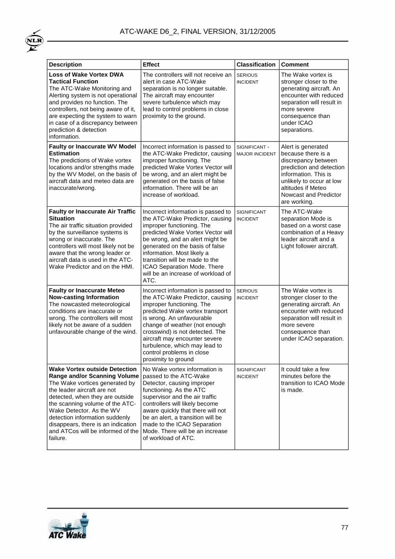
ATC-WAKE D6_2, FINAL VERSION, 31/12/2005
77
Description Effect Classification Comment
Loss of Wake Vortex DWA Tactical Function The ATC-Wake Monitoring and Alerting system is not operational and provides no function. The controllers, not being aware of it, are expecting the system to warn in case of a discrepancy between prediction & detection information.
The controllers will not receive an alert in case ATC-Wake separation is no longer suitable. The aircraft may encounter severe turbulence which may lead to control problems in close proximity to the ground.
SERIOUS
INCIDENT The Wake vortex is stronger closer to the generating aircraft. An encounter with reduced separation will result in more severe consequence than under ICAO separations.
Faulty or Inaccurate WV Model Estimation The predictions of Wake vortex locations and/or strengths made by the WV Model, on the basis of aircraft data and meteo data are inaccurate/wrong.
Incorrect information is passed to the ATC-Wake Predictor, causing improper functioning. The predicted Wake Vortex Vector will be wrong, and an alert might be generated on the basis of false information. There will be an increase of workload.
SIGNIFICANT - MAJOR INCIDENT
Alert is generated because there is a discrepancy between prediction and detection information. This is unlikely to occur at low altitudes if Meteo Nowcast and Predictor are working.
Faulty or Inaccurate Air Traffic Situation The air traffic situation provided by the surveillance systems is wrong or inaccurate. The controllers will most likely not be aware that the wrong leader or aircraft data is used in the ATC-Wake Predictor and on the HMI.
Incorrect information is passed to the ATC-Wake Predictor, causing improper functioning. The predicted Wake Vortex Vector will be wrong, and an alert might be generated on the basis of false information. Most likely a transition will be made to the ICAO Separation Mode. There will be an increase of workload of ATC.
SIGNIFICANT
INCIDENT The ATC-Wake separation Mode is based on a worst case combination of a Heavy leader aircraft and a Light follower aircraft.
Faulty or Inaccurate Meteo Now-casting Information The nowcasted meteorological conditions are inaccurate or wrong. The controllers will most likely not be aware of a sudden unfavourable change of the wind.
Incorrect information is passed to the ATC-Wake Predictor, causing improper functioning. The predicted Wake vortex transport is wrong. An unfavourable change of weather (not enough crosswind) is not detected. The aircraft may encounter severe turbulence, which may lead to control problems in close proximity to ground
SERIOUS
INCIDENT The Wake vortex is stronger closer to the generating aircraft. An encounter with reduced separation will result in more severe consequence than under ICAO separation.
Wake Vortex outside Detection Range and/or Scanning Volume The Wake vortices generated by the leader aircraft are not detected, when they are outside the scanning volume of the ATC-Wake Detector. As the WV detection information suddenly disappears, there is an indication and ATCos will be informed of the failure.
No Wake vortex information is passed to the ATC-Wake Detector, causing improper functioning. As the ATC supervisor and the air traffic controllers will likely become aware quickly that there will not be an alert, a transition will be made to the ICAO Separation Mode. There will be an increase of workload of ATC.
SIGNIFICANT
INCIDENT It could take a few minutes before the transition to ICAO Mode is made.
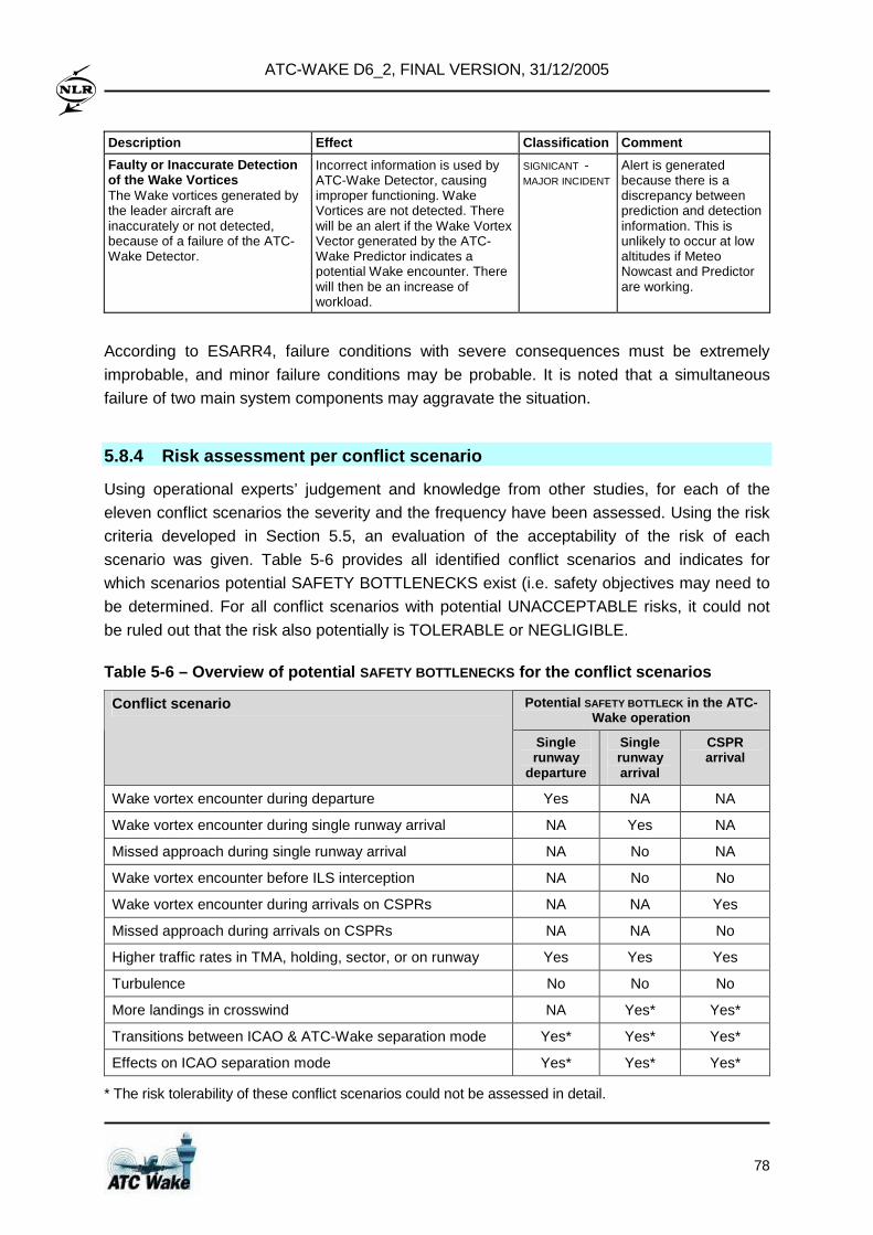
ATC-WAKE D6_2, FINAL VERSION, 31/12/2005
78
Description Effect Classification Comment
Faulty or Inaccurate Detection of the Wake Vortices The Wake vortices generated by the leader aircraft are inaccurately or not detected, because of a failure of the ATC-Wake Detector.
Incorrect information is used by ATC-Wake Detector, causing improper functioning. Wake Vortices are not detected. There will be an alert if the Wake Vortex Vector generated by the ATC-Wake Predictor indicates a potential Wake encounter. There will then be an increase of workload.
SIGNICANT - MAJOR INCIDENT
Alert is generated because there is a discrepancy between prediction and detection information. This is unlikely to occur at low altitudes if Meteo Nowcast and Predictor are working.
According to ESARR4, failure conditions with severe consequences must be extremely
improbable, and minor failure conditions may be probable. It is noted that a simultaneous
failure of two main system components may aggravate the situation.
5.8.4 Risk assessment per conflict scenario
Using operational experts’ judgement and knowledge from other studies, for each of the
eleven conflict scenarios the severity and the frequency have been assessed. Using the risk
criteria developed in Section 5.5, an evaluation of the acceptability of the risk of each
scenario was given. Table 5-6 provides all identified conflict scenarios and indicates for
which scenarios potential SAFETY BOTTLENECKS exist (i.e. safety objectives may need to
be determined. For all conflict scenarios with potential UNACCEPTABLE risks, it could not
be ruled out that the risk also potentially is TOLERABLE or NEGLIGIBLE.
Table 5-6 – Overview of potential SAFETY BOTTLENECKS for the conflict scenarios
Potential SAFETY BOTTLECK in the ATC-Wake operation
Conflict scenario
Single runway
departure
Single runway arrival
CSPR arrival
Wake vortex encounter during departure Yes NA NA
Wake vortex encounter during single runway arrival NA Yes NA
Missed approach during single runway arrival NA No NA
Wake vortex encounter before ILS interception NA No No
Wake vortex encounter during arrivals on CSPRs NA NA Yes
Missed approach during arrivals on CSPRs NA NA No
Higher traffic rates in TMA, holding, sector, or on runway Yes Yes Yes
Turbulence No No No
More landings in crosswind NA Yes* Yes*
Transitions between ICAO & ATC-Wake separation mode Yes* Yes* Yes*
Effects on ICAO separation mode Yes* Yes* Yes*
* The risk tolerability of these conflict scenarios could not be assessed in detail.
ATC-WAKE D6_2, FINAL VERSION, 31/12/2005
79
5.8.5 Identification of safety bottlenecks
The possibility of UNACCEPTABLE risk could not be ruled out in the conflict scenarios I, II,
V, VII, IX, X and XI. This is potentially caused by so-called safety bottlenecks: hazards which
cause the conflict scenario to have a risk that might be UNACCEPTABLE. The safety
bottlenecks in the concerned conflict scenarios are discussed next.
In conflict scenario I (Wake vortex encounter during departure), identified potential safety
bottlenecks are:
• Supervisors may not follow the advice of the ATC-Wake Separation Mode Planner and
tend to deviate to the unsafe side, for example for efficiency reasons;
• Controllers may not comply with the prescribed separation and give a take-off clearance
too early, for instance due to a timing error;
• Controllers may not pay sufficient attention to the visualisation tool and react properly on
an alert, because TWR controllers are used to work based on their outside view,
specifically in VMC.
In the departure operation the risk is mainly expected in the area just after lift-off, though also
the area around the first turn may bear a significant risk.
In conflict scenario II (Wake vortex encounter during single runway arrival), an identified
potential safety bottleneck is:
• Controllers may use the Wake vortex visualisation system as a separation tool (although
this is not the objective of the tool), possibly leading to insufficient spacing.
It is expected that the highest risk occurs on the final approach (from 4Nm to threshold) while
the area where the ILS intercept takes place is also prone to Wake encounters.
Conflict scenario V (Wake vortex encounter during arrivals on closely spaced parallel
runway) is expected to be less safety critical than conflict scenario II. Identified potential
safety bottlenecks are:
• Controllers may use the Wake vortex visualisation system as a separation tool (although
this is not the objective of the tool), possibly leading to insufficient spacing;
• The use of a single controller for the two runways.
In conflict scenario VII (Higher traffic rates in TMA), holding, sector or on runway, identified
potential safety bottlenecks are:
• Frequency congestion due to the expected increase in R/T load. This increase is
expected firstly because of the additional information that needs to be given to the pilots,
and secondly to the increase in traffic rates that is expected.
• Collision risk on the runway, because of the application of reduced separation criteria to
all pairs of aircraft, irrespective of the aircraft types. If the ATC-Wake mode separation
distance does not sufficiently take into account the runway occupancy time of Heavy
aircraft, this is expected to lead to an increased collision risk on the runway. If the ATC-
ATC-WAKE D6_2, FINAL VERSION, 31/12/2005
80
Wake mode separation distance would safely account for the runway occupancy time of
Heavy aircraft, then the use of this separation distance for all aircraft types is not
expected to support the capacity increase envisioned by the ATC-Wake operation.
In conflict scenario IX (More landings in crosswind) a potential safety bottleneck is:
• Adapted runway selection criteria may favour landing in crosswinds of 10 to 15 knots and
higher above landing in headwind.
In conflict scenario X (Transitions between ICAO and ATC-Wake separation mode) potential
safety bottlenecks are:
• Too frequent or sudden mode transitions;
• Too much information exchange in a transition.
In conflict scenario XI (Effects on ICAO separation mode) a potential safety bottleneck is:
• The possible use of the ATC-Wake visualisation system as a separation tool. This may
be the case if the system is available to the controllers in the ICAO separation mode.
For the other scenarios no UNACCEPTABLE risks were identified. These scenarios are:
III. Missed approach during single runway arrival
IV. Wake vortex encounter before ILS interception
VI. Missed approach during arrivals on closely spaced parallel runways
VIII. Turbulence
5.8.6 Enhancements of the ATC-Wake operation
Comments and recommendations on elements related to the ATC-Wake operation were
given by some operational and safety experts in the review of this study. These may be
valuable for the further design and implementation of the ATC-Wake operation as they may
contribute to the resolution or mitigation of the potential safety bottlenecks. The hazard
identification and the analysis of hazards and conflict scenarios have however been
performed for an operation in which these aspects were not (yet) present. Since for these
aspects it was not straightforward to identify whether they would introduce any new hazards
to the operation, they have not been taken into account. These aspects are:
• In addition to the assumption that airborne equipment for Wake vortex detection, as the I-
Wake system may in future function as a safety-net to the ATC-Wake system, it is
remarked that such an I-Wake system would not be considered as a potential mitigation
mean in a future safety assessment but would act as a last safety resort.
• In view of the not stabilised description of atmospheric conditions for which one of the two
envisaged separation modes (ICAO Mode or ATC-Wake Mode) must be used, it is
strongly recommended to focus the further elaboration of weather classes on
ATC-WAKE D6_2, FINAL VERSION, 31/12/2005
81
atmospheric conditions that are relatively easy to forecast (prediction of wind climatology
is easy, whereas atmospheric turbulence and stratification are difficult to forecast).
• In view of the visual contact between two consecutive landing aircraft that has to be
confirmed as soon as the second aircraft intercepts ILS, as proposed in the operation, it
is noted that this may be more important on final approach such that the following aircraft
can see if the preceding aircraft has vacated the runway or has initiated a go-around.
• In addition to what is proposed with respect to ATIS in the operation, it is very important
that ATIS information also includes information on the ATC Wake Procedure
(meteorological and visuals conditions) and the possibility that there might be an alert
due to low separation.
• In addition to what is proposed with respect to SMGCS in the operation, A-SMGCS may
be required as well for the ATC-Wake operation, to provide the controller with aircraft
position and identification on a radar display. Such facility may be required as higher
landing rates or departure rates may be expected in the ATC-Wake operation.
• In order to safely support reduced separation, the detection information shall also have a
high level of integrity and continuity of service in addition to accuracy. This substantiates
the need for an ATC-Wake monitoring and alerting system.
• In view of the information that "deviation from separation by the ATCo seems to be daily
practice", in the training for new operations it should be explained that current practice
operations were designed with large embedded safety buffers because of the
uncertainties of the systems and about the raw information. Less additional buffer is
expected on new operations that will be designed on more accurate raw data.
• TCAS is used to estimate distances with an accuracy of about 1 NM. However, bearing
information is only relative bearing and is very uncertain. Relative bearing must not be
used to estimate the track of the other aircraft. This is normally part of the TCAS training
but it should be emphasized for Wake vortex training. In fact, there could be a
requirement to have an airborne system enabling to monitor the spacing distance with the
preceding aircraft (see http://adsb.tc.faa.gov/WG4.htm).
5.9 Quantitative safety assessment 5.9.1 Overview of the simulation scenarios
The set up and results of the quantitative risk assessment of the ATC-Wake operation are
obtained using the quantitative risk assessment methodology described in Section 5.3. The
assessments have been performed for the "current practice", i.e. without the use of an ATC-
Wake system, and also for the proposed ATC-Wake operation. Three studies have been
carried out:
• Single runway arrivals
• Single runway departures
• Closely spaced parallel runway arrivals
ATC-WAKE D6_2, FINAL VERSION, 31/12/2005
82
Basically, the scenarios that have been set up differ in:
• Generator – follower aircraft combination;
• Wind velocity (direction and strength);
• Separation distance or time.
These are called ‘assessment parameters’. A simulation scenario is defined by all the
parameters and variables in the WAVIR tool-set. The main deterministic parameters and
stochastic variables and their values in the different scenarios are presented below.
Longitudinal positions along the flight track Analysis of wake induced risk is done in a number of longitudinal positions up to 10 Nm from
the runway thresholds. From the qualitative analysis it appears that the following areas might
be the most dangerous: the area close to the ground, the area encompassing the first turn in
the climb phase, and the area near ILS interception.
Wake vortex evolution model parameters The vortex pair behind the generator aircraft is modelled as two line vortices with a vortex
spacing, a vortex strength, and a core-radius. These parameters do depend on the
wingspan, weight and speed of the generator aircraft. Evolution of the vortex position is
modelled according to Corjon&Poinsot. This includes image vortices and secondary vortices
making the vortex pair to diverge and rebound near the ground respectively. Parameters
concerning secondary vortices are:
• strength of the secondary vortices as a fraction of the strength of the primary vortices;
and the
• rebound height
A secondary vortex appears as soon as the primary vortex has decreased to a certain
altitude: the rebound height. For the rebound height a fixed value of 0.6b0 will be used. The
strength of the secondary vortex is a fraction of the strength of the primary vortex. This
fraction is drawn from an uniform distribution between 0.3 and 0.7.
Decay model The decay function as defined by Sarpkaya will be used. Input parameters are the Brunt-
Väisälä frequency N and the Eddy Dissipation Rate (EDR).
Meteorological input parameters • Brunt-Väisälä frequency (N)
• Eddy Dissipation Rate (EDR)
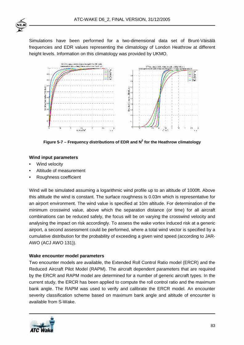
ATC-WAKE D6_2, FINAL VERSION, 31/12/2005
83
Simulations have been performed for a two-dimensional data set of Brunt-Väisälä
frequencies and EDR values representing the climatology of London Heathrow at different
height levels. Information on this climatology was provided by UKMO.
Figure 5-7 – Frequency distributions of EDR and N 2 for the Heathrow climatology
Wind input parameters • Wind velocity
• Altitude of measurement
• Roughness coefficient
Wind will be simulated assuming a logarithmic wind profile up to an altitude of 1000ft. Above
this altitude the wind is constant. The surface roughness is 0.03m which is representative for
an airport environment. The wind value is specified at 10m altitude. For determination of the
minimum crosswind value, above which the separation distance (or time) for all aircraft
combinations can be reduced safely, the focus will be on varying the crosswind velocity and
analysing the impact on risk accordingly. To assess the wake vortex induced risk at a generic
airport, a second assessment could be performed, where a total wind vector is specified by a
cumulative distribution for the probability of exceeding a given wind speed (according to JAR-
AWO (ACJ AWO 131)).
Wake encounter model parameters Two encounter models are available, the Extended Roll Control Ratio model (ERCR) and the
Reduced Aircraft Pilot Model (RAPM). The aircraft dependent parameters that are required
by the ERCR and RAPM model are determined for a number of generic aircraft types. In the
current study, the ERCR has been applied to compute the roll control ratio and the maximum
bank angle. The RAPM was used to verify and calibrate the ERCR model. An encounter
severity classification scheme based on maximum bank angle and altitude of encounter is
available from S-Wake.
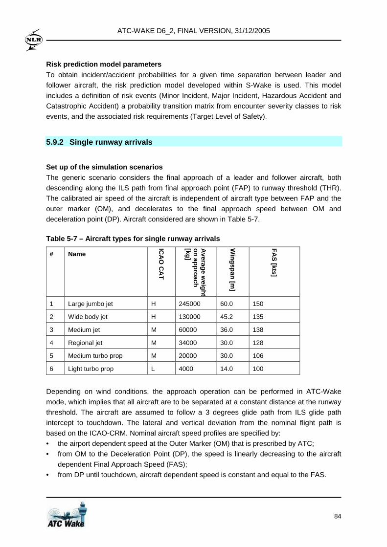
ATC-WAKE D6_2, FINAL VERSION, 31/12/2005
84
Risk prediction model parameters To obtain incident/accident probabilities for a given time separation between leader and
follower aircraft, the risk prediction model developed within S-Wake is used. This model
includes a definition of risk events (Minor Incident, Major Incident, Hazardous Accident and
Catastrophic Accident) a probability transition matrix from encounter severity classes to risk
events, and the associated risk requirements (Target Level of Safety).
5.9.2 Single runway arrivals
Set up of the simulation scenarios The generic scenario considers the final approach of a leader and follower aircraft, both
descending along the ILS path from final approach point (FAP) to runway threshold (THR).
The calibrated air speed of the aircraft is independent of aircraft type between FAP and the
outer marker (OM), and decelerates to the final approach speed between OM and
deceleration point (DP). Aircraft considered are shown in Table 5-7.
Table 5-7 – Aircraft types for single runway arriva ls
# Name
ICA
O C
AT
Average w
eight on approach [kg]
Wingspan [m
]
FA
S [kts]
1 Large jumbo jet H 245000 60.0 150
2 Wide body jet H 130000 45.2 135
3 Medium jet M 60000 36.0 138
4 Regional jet M 34000 30.0 128
5 Medium turbo prop M 20000 30.0 106
6 Light turbo prop L 4000 14.0 100
Depending on wind conditions, the approach operation can be performed in ATC-Wake
mode, which implies that all aircraft are to be separated at a constant distance at the runway
threshold. The aircraft are assumed to follow a 3 degrees glide path from ILS glide path
intercept to touchdown. The lateral and vertical deviation from the nominal flight path is
based on the ICAO-CRM. Nominal aircraft speed profiles are specified by:
• the airport dependent speed at the Outer Marker (OM) that is prescribed by ATC;
• from OM to the Deceleration Point (DP), the speed is linearly decreasing to the aircraft
dependent Final Approach Speed (FAS);
• from DP until touchdown, aircraft dependent speed is constant and equal to the FAS.
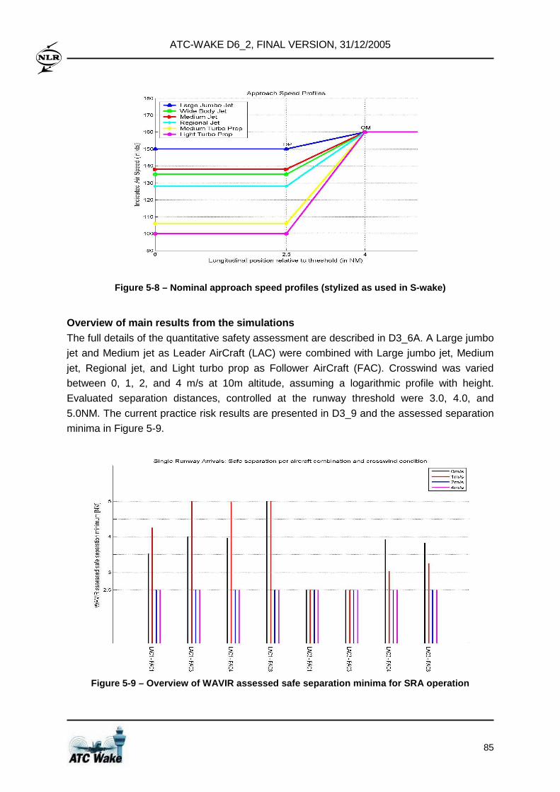
ATC-WAKE D6_2, FINAL VERSION, 31/12/2005
85
Figure 5-8 – Nominal approach speed profiles (styli zed as used in S-wake)
Overview of main results from the simulations The full details of the quantitative safety assessment are described in D3_6A. A Large jumbo
jet and Medium jet as Leader AirCraft (LAC) were combined with Large jumbo jet, Medium
jet, Regional jet, and Light turbo prop as Follower AirCraft (FAC). Crosswind was varied
between 0, 1, 2, and 4 m/s at 10m altitude, assuming a logarithmic profile with height.
Evaluated separation distances, controlled at the runway threshold were 3.0, 4.0, and
5.0NM. The current practice risk results are presented in D3_9 and the assessed separation
minima in Figure 5-9.
Figure 5-9 – Overview of WAVIR assessed safe separa tion minima for SRA operation
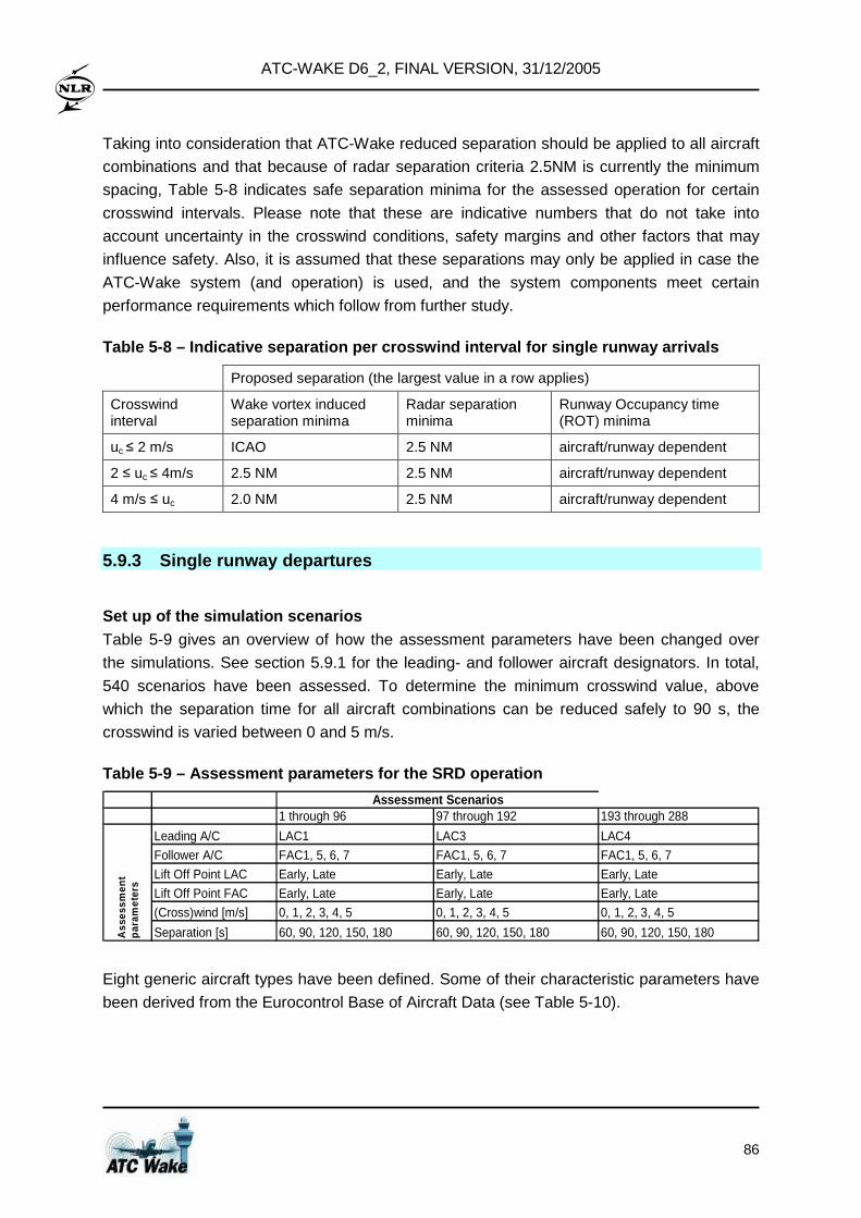
ATC-WAKE D6_2, FINAL VERSION, 31/12/2005
86
Taking into consideration that ATC-Wake reduced separation should be applied to all aircraft
combinations and that because of radar separation criteria 2.5NM is currently the minimum
spacing, Table 5-8 indicates safe separation minima for the assessed operation for certain
crosswind intervals. Please note that these are indicative numbers that do not take into
account uncertainty in the crosswind conditions, safety margins and other factors that may
influence safety. Also, it is assumed that these separations may only be applied in case the
ATC-Wake system (and operation) is used, and the system components meet certain
performance requirements which follow from further study.
Table 5-8 – Indicative separation per crosswind int erval for single runway arrivals
Proposed separation (the largest value in a row applies)
Crosswind interval
Wake vortex induced separation minima
Radar separation minima
Runway Occupancy time (ROT) minima
uc ≤ 2 m/s ICAO 2.5 NM aircraft/runway dependent
2 ≤ uc ≤ 4m/s 2.5 NM 2.5 NM aircraft/runway dependent
4 m/s ≤ uc 2.0 NM 2.5 NM aircraft/runway dependent
5.9.3 Single runway departures
Set up of the simulation scenarios Table 5-9 gives an overview of how the assessment parameters have been changed over
the simulations. See section 5.9.1 for the leading- and follower aircraft designators. In total,
540 scenarios have been assessed. To determine the minimum crosswind value, above
which the separation time for all aircraft combinations can be reduced safely to 90 s, the
crosswind is varied between 0 and 5 m/s.
Table 5-9 – Assessment parameters for the SRD opera tion
1 through 96 97 through 192 193 through 288
Leading A/C LAC1 LAC3 LAC4
Follower A/C FAC1, 5, 6, 7 FAC1, 5, 6, 7 FAC1, 5, 6, 7
Lift Off Point LAC Early, Late Early, Late Early, Late
Lift Off Point FAC Early, Late Early, Late Early, Late
(Cross)wind [m/s] 0, 1, 2, 3, 4, 5 0, 1, 2, 3, 4, 5 0, 1, 2, 3, 4, 5
Separation [s] 60, 90, 120, 150, 180 60, 90, 120, 150, 180 60, 90, 120, 150, 180
Assessment Scenarios
Ass
essm
ent
para
met
ers
Eight generic aircraft types have been defined. Some of their characteristic parameters have
been derived from the Eurocontrol Base of Aircraft Data (see Table 5-10).
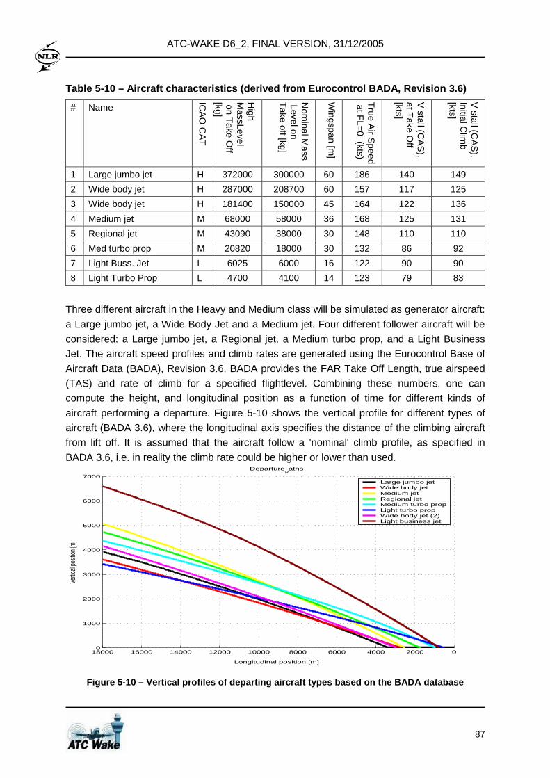
ATC-WAKE D6_2, FINAL VERSION, 31/12/2005
87
Table 5-10 – Aircraft characteristics (derived from Eurocontrol BADA, Revision 3.6)
# Name
ICA
O C
AT
High
MassLevel
on Take O
ff [kg]
Nom
inal Mass
Level on T
ake off [kg]
Wingspan [m
]
True A
ir Sp eed
at FL=
0 (kts) V
stall (CA
S),
at Take O
ff [kts]
V stall (C
AS
), Initial C
limb
[kts]
1 Large jumbo jet H 372000 300000 60 186 140 149
2 Wide body jet H 287000 208700 60 157 117 125
3 Wide body jet H 181400 150000 45 164 122 136
4 Medium jet M 68000 58000 36 168 125 131
5 Regional jet M 43090 38000 30 148 110 110
6 Med turbo prop M 20820 18000 30 132 86 92
7 Light Buss. Jet L 6025 6000 16 122 90 90
8 Light Turbo Prop L 4700 4100 14 123 79 83
Three different aircraft in the Heavy and Medium class will be simulated as generator aircraft:
a Large jumbo jet, a Wide Body Jet and a Medium jet. Four different follower aircraft will be
considered: a Large jumbo jet, a Regional jet, a Medium turbo prop, and a Light Business
Jet. The aircraft speed profiles and climb rates are generated using the Eurocontrol Base of
Aircraft Data (BADA), Revision 3.6. BADA provides the FAR Take Off Length, true airspeed
(TAS) and rate of climb for a specified flightlevel. Combining these numbers, one can
compute the height, and longitudinal position as a function of time for different kinds of
aircraft performing a departure. Figure 5-10 shows the vertical profile for different types of
aircraft (BADA 3.6), where the longitudinal axis specifies the distance of the climbing aircraft
from lift off. It is assumed that the aircraft follow a 'nominal' climb profile, as specified in
BADA 3.6, i.e. in reality the climb rate could be higher or lower than used.
0200040006000800010000120001400016000180000
1000
2000
3000
4000
5000
6000
7000
Departurepaths
Longitudinal position [m]
Vertic
al po
sition
[m]
Large jumbo jetWide body jetMedium jetRegional jetMedium turbo propLight turbo propWide body jet (2)Light business jet
Figure 5-10 – Vertical profiles of departing aircra ft types based on the BADA database
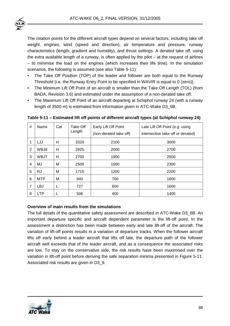
ATC-WAKE D6_2, FINAL VERSION, 31/12/2005
88
The rotation points for the different aircraft types depend on several factors, including take off
weight, engines, wind (speed and direction), air temperature and pressure, runway
characteristics (length, gradient and humidity), and thrust settings. A derated take off, using
the extra available length of a runway, is often applied by the pilot – at the request of airlines
– to minimise the load on the engines (which increases their life time). In the simulation
scenarios, the following is assumed (see also Table 5-11):
• The Take Off Position (TOP) of the leader and follower are both equal to the Runway
Threshold (i.e. the Runway Entry Point to be specified in WAVIR is equal to 0 (zero)).
• The Minimum Lift Off Point of an aircraft is smaller than the Take Off Length (TOL) (from
BADA, Revision 3.6) and estimated under the assumption of a non-derated take off.
• The Maximum Lift Off Point of an aircraft departing at Schiphol runway 24 (with a runway
length of 3500 m) is estimated from information given in ATC-Wake D3_6B.
Table 5-11 – Estimated lift off points of different aircraft types (at Schiphol runway 24)
# Name Cat Take Off Length
Early Lift Off Point
(non-derated take off)
Late Lift Off Point (e.g. using
intersection take off or derated)
1 LJJ H 3320 2100 3000
2 WBJ6 H 2925 2000 2700
3 WBJ7 H 2700 1900 2500
4 MJ M 2500 1500 2300
5 RJ M 1715 1200 2200
6 MTP M 940 700 1800
7 LBJ L 727 600 1600
8 LTP L 506 400 1400
Overview of main results from the simulations The full details of the quantitative safety assessment are described in ATC-Wake D3_6B. An
important departure specific and aircraft dependent parameter is the lift-off point. In the
assessment a distinction has been made between early and late lift-off of the aircraft. The
variation of lift-off points results in a variation of departure tracks. When the follower aircraft
lifts off early behind a leader aircraft that lifts off late, the departure path of the follower
aircraft well exceeds that of the leader aircraft, and as a consequence the associated risks
are low. To stay on the conservative side, the risk results have been maximised over the
variation in lift-off point before deriving the safe separation minima presented in Figure 5-11.
Associated risk results are given in D3_9.
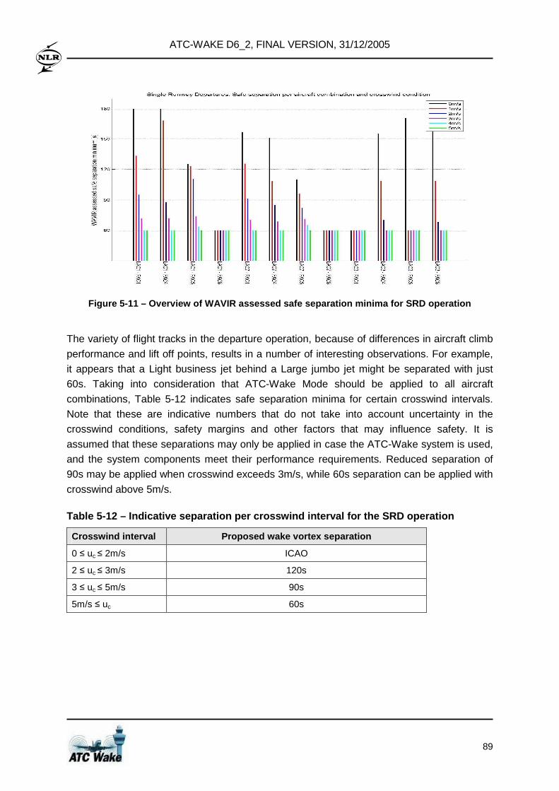
ATC-WAKE D6_2, FINAL VERSION, 31/12/2005
89
Figure 5-11 – Overview of WAVIR assessed safe separ ation minima for SRD operation
The variety of flight tracks in the departure operation, because of differences in aircraft climb
performance and lift off points, results in a number of interesting observations. For example,
it appears that a Light business jet behind a Large jumbo jet might be separated with just
60s. Taking into consideration that ATC-Wake Mode should be applied to all aircraft
combinations, Table 5-12 indicates safe separation minima for certain crosswind intervals.
Note that these are indicative numbers that do not take into account uncertainty in the
crosswind conditions, safety margins and other factors that may influence safety. It is
assumed that these separations may only be applied in case the ATC-Wake system is used,
and the system components meet their performance requirements. Reduced separation of
90s may be applied when crosswind exceeds 3m/s, while 60s separation can be applied with
crosswind above 5m/s.
Table 5-12 – Indicative separation per crosswind in terval for the SRD operation
Crosswind interval Proposed wake vortex separation
0 ≤ uc ≤ 2m/s ICAO
2 ≤ uc ≤ 3m/s 120s
3 ≤ uc ≤ 5m/s 90s
5m/s ≤ uc 60s
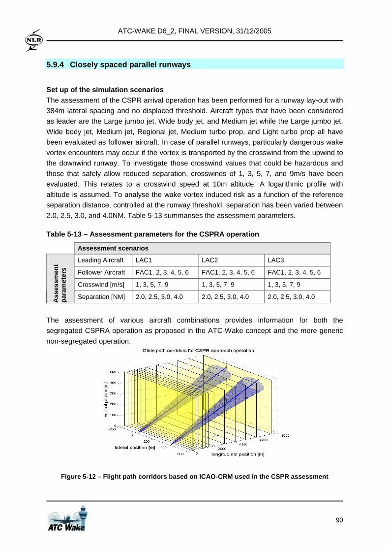
ATC-WAKE D6_2, FINAL VERSION, 31/12/2005
90
5.9.4 Closely spaced parallel runways
Set up of the simulation scenarios The assessment of the CSPR arrival operation has been performed for a runway lay-out with
384m lateral spacing and no displaced threshold. Aircraft types that have been considered
as leader are the Large jumbo jet, Wide body jet, and Medium jet while the Large jumbo jet,
Wide body jet, Medium jet, Regional jet, Medium turbo prop, and Light turbo prop all have
been evaluated as follower aircraft. In case of parallel runways, particularly dangerous wake
vortex encounters may occur if the vortex is transported by the crosswind from the upwind to
the downwind runway. To investigate those crosswind values that could be hazardous and
those that safely allow reduced separation, crosswinds of 1, 3, 5, 7, and 9m/s have been
evaluated. This relates to a crosswind speed at 10m altitude. A logarithmic profile with
altitude is assumed. To analyse the wake vortex induced risk as a function of the reference
separation distance, controlled at the runway threshold, separation has been varied between
2.0, 2.5, 3.0, and 4.0NM. Table 5-13 summarises the assessment parameters.
Table 5-13 – Assessment parameters for the CSPRA op eration
Assessment scenarios
Leading Aircraft LAC1 LAC2 LAC3
Follower Aircraft FAC1, 2, 3, 4, 5, 6 FAC1, 2, 3, 4, 5, 6 FAC1, 2, 3, 4, 5, 6
Crosswind [m/s] 1, 3, 5, 7, 9 1, 3, 5, 7, 9 1, 3, 5, 7, 9
Ass
essm
ent
para
met
ers
Separation [NM] 2.0, 2.5, 3.0, 4.0 2.0, 2.5, 3.0, 4.0 2.0, 2.5, 3.0, 4.0
The assessment of various aircraft combinations provides information for both the
segregated CSPRA operation as proposed in the ATC-Wake concept and the more generic
non-segregated operation.
Figure 5-12 – Flight path corridors based on ICAO-C RM used in the CSPR assessment
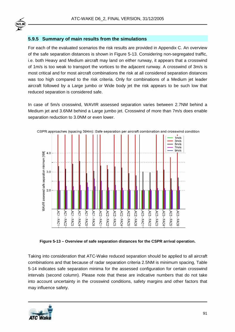
ATC-WAKE D6_2, FINAL VERSION, 31/12/2005
91
5.9.5 Summary of main results from the simulations
For each of the evaluated scenarios the risk results are provided in Appendix C. An overview
of the safe separation distances is shown in Figure 5-13. Considering non-segregated traffic,
i.e. both Heavy and Medium aircraft may land on either runway, it appears that a crosswind
of 1m/s is too weak to transport the vortices to the adjacent runway. A crosswind of 3m/s is
most critical and for most aircraft combinations the risk at all considered separation distances
was too high compared to the risk criteria. Only for combinations of a Medium jet leader
aircraft followed by a Large jumbo or Wide body jet the risk appears to be such low that
reduced separation is considered safe.
In case of 5m/s crosswind, WAVIR assessed separation varies between 2.7NM behind a
Medium jet and 3.6NM behind a Large jumbo jet. Crosswind of more than 7m/s does enable
separation reduction to 3.0NM or even lower.
Figure 5-13 – Overview of safe separation distances for the CSPR arrival operation.
Taking into consideration that ATC-Wake reduced separation should be applied to all aircraft
combinations and that because of radar separation criteria 2.5NM is minimum spacing, Table
5-14 indicates safe separation minima for the assessed configuration for certain crosswind
intervals (second column). Please note that these are indicative numbers that do not take
into account uncertainty in the crosswind conditions, safety margins and other factors that
may influence safety.
ATC-WAKE D6_2, FINAL VERSION, 31/12/2005
92
When considering segregated traffic, i.e. Heavy aircraft (like Large jumbo jet and Wide body
jet) are only allowed on the downwind runway, the worst case situation is when the vortices
of a Medium aircraft (like Medium jet) on the upwind runway are encountered by a Heavy
aircraft (like Wide body jet) on the downwind runway. Following the results as presented in
Figure 5-13, indicative separation minima then become as listed in the third column of Table
5-14. A less strict segregation of traffic, indicated as 'semi-segregated', may allow Medium
aircraft also on the downwind runway. Then, the worst case situation is when the vortices of
a Medium aircraft (like Medium jet) on the upwind runway are encountered by a Medium
aircraft (like Medium turbo prop) on the downwind runway and indicative separation minima
become as listed in the fourth column of Table 5-14.
Table 5-14 – Indicative separation per crosswind in terval for the CSPRA operation
Proposed separation
Crosswind interval
Non-segregated traffic
Segregated traffic (Heavy only on downwind runway)
Semi-segregated traffic (Heavy and Medium on downwind runway)
0 ≤ uc ≤ 1m/s 2.5NM 2.5NM 2.5NM
1 ≤ uc ≤ 4m/s ICAO 2.5NM ICAO
4 ≤ uc ≤ 6m/s 4.0NM 3.0NM 3.5NM
6 ≤ uc ≤ 8m/s 3.0NM 2.5NM 2.5NM
8m/s ≤ uc 2.5NM 2.5NM 2.5NM
In all three considered cases, reduced separation may be applied for especially weak
crosswinds (in between 0 and 1 m/s) and strong crosswinds (above 8m/s). Segregation of
traffic enables reduced separation for all crosswinds while for semi-segregated traffic ICAO
separation should be applied when the crosswind is in between 1 and 4m/s. Note that such
calculated crosswind intervals strongly depend on the runway spacing.
5.10 Overview of proposed ATC-Wake Mode separations
Indicative separation minima have been derived for each of the 3 ATC-Wake operations, and
indicative tables have been derived that link the prevailing crosswind speed to the separation
to be applied in ATC-Wake Mode. The results are summarised in Table 5-15. The crosswind
intervals have now been split up to bins of 1m/s width. A crosswind climatology based on
400,000 observations at about 10 European airports has been used to determine the
probabilities of occurrence of the crosswind interval. The data source itself is confidential.
Crosswind from left and right appeared to be equally likely. The resulting crosswind
probabilities listed in Table 5-15 give an indication about the likelihood of certain (wind)
conditions.
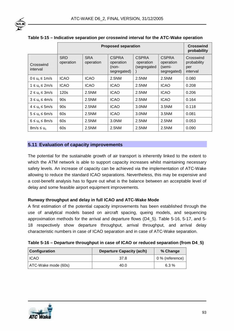
ATC-WAKE D6_2, FINAL VERSION, 31/12/2005
93
Table 5-15 – Indicative separation per crosswind in terval for the ATC-Wake operation
Proposed separation Crosswind probability
Crosswind interval
SRD operation
SRA operation
CSPRA operation (non- segregated)
CSPRA operation (segregated)
CSPRA operation (semi- segregated)
Crosswind probability per interval
0 ≤ uc ≤ 1m/s ICAO ICAO 2.5NM 2.5NM 2.5NM 0.080
1 ≤ uc ≤ 2m/s ICAO ICAO ICAO 2.5NM ICAO 0.208
2 ≤ uc ≤ 3m/s 120s 2.5NM ICAO 2.5NM ICAO 0.206
3 ≤ uc ≤ 4m/s 90s 2.5NM ICAO 2.5NM ICAO 0.164
4 ≤ uc ≤ 5m/s 90s 2.5NM ICAO 3.0NM 3.5NM 0.118
5 ≤ uc ≤ 6m/s 60s 2.5NM ICAO 3.0NM 3.5NM 0.081
6 ≤ uc ≤ 8m/s 60s 2.5NM 3.0NM 2.5NM 2.5NM 0.053
8m/s ≤ uc 60s 2.5NM 2.5NM 2.5NM 2.5NM 0.090
5.11 Evaluation of capacity improvements
The potential for the sustainable growth of air transport is inherently linked to the extent to
which the ATM network is able to support capacity increases whilst maintaining necessary
safety levels. An increase of capacity can be achieved via the implementation of ATC-Wake
allowing to reduce the standard ICAO separations. Nevertheless, this may be expensive and
a cost-benefit analysis has to figure out what is the balance between an acceptable level of
delay and some feasible airport equipment improvements.
Runway throughput and delay in full ICAO and ATC-Wa ke Mode A first estimation of the potential capacity improvements has been established through the
use of analytical models based on aircraft spacing, queing models, and sequencing
approximation methods for the arrival and departure flows (D4_5). Table 5-16, 5-17, and 5-
18 respectively show departure throughput, arrival throughput, and arrival delay
characteristic numbers in case of ICAO separation and in case of ATC-Wake separation.
Table 5-16 – Departure throughput in case of ICAO o r reduced separation (from D4_5)
Configuration Departure Capacity (ac/h) % Change
ICAO 37.8 0 % (reference)
ATC-Wake mode (60s) 40.0 6.3 %
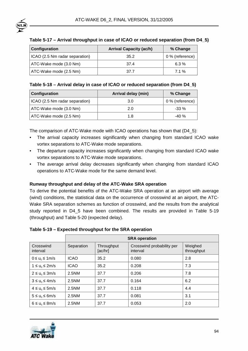
ATC-WAKE D6_2, FINAL VERSION, 31/12/2005
94
Table 5-17 – Arrival throughput in case of ICAO or reduced separation (from D4_5)
Configuration Arrival Capacity (ac/h) % Change
ICAO (2.5 Nm radar separation) 35.2 0 % (reference)
ATC-Wake mode (3.0 Nm) 37.4 6.3 %
ATC-Wake mode (2.5 Nm) 37.7 7.1 %
Table 5-18 – Arrival delay in case of ICAO or reduc ed separation (from D4_5)
Configuration Arrival delay (min) % Change
ICAO (2.5 Nm radar separation) 3.0 0 % (reference)
ATC-Wake mode (3.0 Nm) 2.0 -33 %
ATC-Wake mode (2.5 Nm) 1.8 -40 %
The comparison of ATC-Wake mode with ICAO operations has shown that (D4_5):
• The arrival capacity increases significantly when changing from standard ICAO wake
vortex separations to ATC-Wake mode separations.
• The departure capacity increases significantly when changing from standard ICAO wake
vortex separations to ATC-Wake mode separations.
• The average arrival delay decreases significantly when changing from standard ICAO
operations to ATC-Wake mode for the same demand level.
Runway throughput and delay of the ATC-Wake SRA ope ration To derive the potential benefits of the ATC-Wake SRA operation at an airport with average
(wind) conditions, the statistical data on the occurrence of crosswind at an airport, the ATC-
Wake SRA separation schemes as function of crosswind, and the results from the analytical
study reported in D4_5 have been combined. The results are provided in Table 5-19
(throughput) and Table 5-20 (expected delay).
Table 5-19 – Expected throughput for the SRA operat ion
SRA operation
Crosswind interval
Separation Throughput [ac/hr]
Crosswind probability per interval
Weighed throughput
0 ≤ uc ≤ 1m/s ICAO 35.2 0.080 2.8
1 ≤ uc ≤ 2m/s ICAO 35.2 0.208 7.3
2 ≤ uc ≤ 3m/s 2.5NM 37.7 0.206 7.8
3 ≤ uc ≤ 4m/s 2.5NM 37.7 0.164 6.2
4 ≤ uc ≤ 5m/s 2.5NM 37.7 0.118 4.4
5 ≤ uc ≤ 6m/s 2.5NM 37.7 0.081 3.1
6 ≤ uc ≤ 8m/s 2.5NM 37.7 0.053 2.0
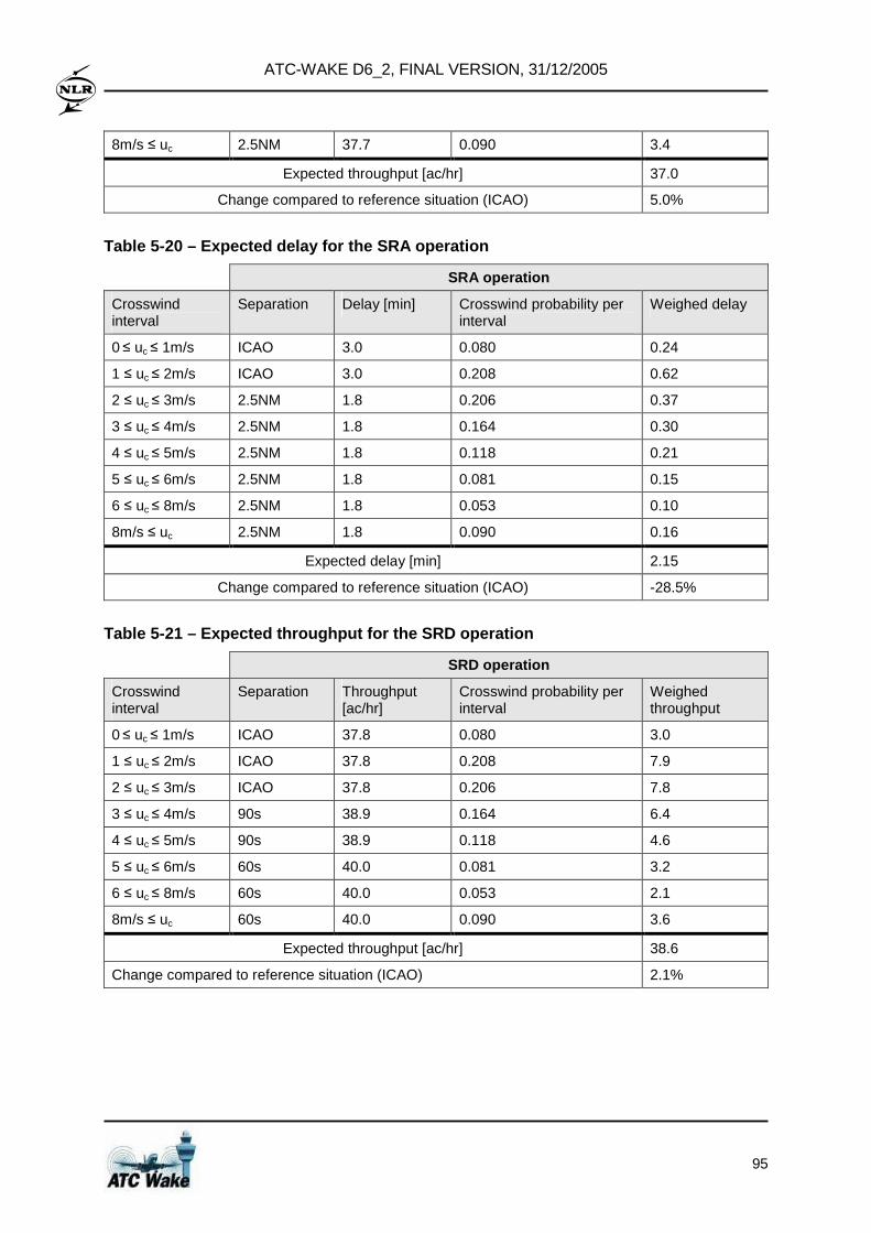
ATC-WAKE D6_2, FINAL VERSION, 31/12/2005
95
8m/s ≤ uc 2.5NM 37.7 0.090 3.4
Expected throughput [ac/hr] 37.0
Change compared to reference situation (ICAO) 5.0%
Table 5-20 – Expected delay for the SRA operation
SRA operation
Crosswind interval
Separation Delay [min] Crosswind probability per interval
Weighed delay
0 ≤ uc ≤ 1m/s ICAO 3.0 0.080 0.24
1 ≤ uc ≤ 2m/s ICAO 3.0 0.208 0.62
2 ≤ uc ≤ 3m/s 2.5NM 1.8 0.206 0.37
3 ≤ uc ≤ 4m/s 2.5NM 1.8 0.164 0.30
4 ≤ uc ≤ 5m/s 2.5NM 1.8 0.118 0.21
5 ≤ uc ≤ 6m/s 2.5NM 1.8 0.081 0.15
6 ≤ uc ≤ 8m/s 2.5NM 1.8 0.053 0.10
8m/s ≤ uc 2.5NM 1.8 0.090 0.16
Expected delay [min] 2.15
Change compared to reference situation (ICAO) -28.5%
Table 5-21 – Expected throughput for the SRD operat ion
SRD operation
Crosswind interval
Separation Throughput [ac/hr]
Crosswind probability per interval
Weighed throughput
0 ≤ uc ≤ 1m/s ICAO 37.8 0.080 3.0
1 ≤ uc ≤ 2m/s ICAO 37.8 0.208 7.9
2 ≤ uc ≤ 3m/s ICAO 37.8 0.206 7.8
3 ≤ uc ≤ 4m/s 90s 38.9 0.164 6.4
4 ≤ uc ≤ 5m/s 90s 38.9 0.118 4.6
5 ≤ uc ≤ 6m/s 60s 40.0 0.081 3.2
6 ≤ uc ≤ 8m/s 60s 40.0 0.053 2.1
8m/s ≤ uc 60s 40.0 0.090 3.6
Expected throughput [ac/hr] 38.6
Change compared to reference situation (ICAO) 2.1%
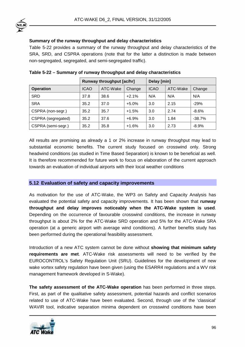
ATC-WAKE D6_2, FINAL VERSION, 31/12/2005
96
Summary of the runway throughput and delay characte ristics Table 5-22 provides a summary of the runway throughput and delay characteristics of the
SRA, SRD, and CSPRA operations (note that for the latter a distinction is made between
non-segregated, segregated, and semi-segregated traffic).
Table 5-22 – Summary of runway throughput and delay characteristics
Runway throughput [ac/hr] Delay [min]
Operation ICAO ATC-Wake Change ICAO ATC-Wake Change
SRD 37.8 38.6 +2.1% N/A N/A N/A
SRA 35.2 37.0 +5.0% 3.0 2.15 -29%
CSPRA (non-segr.) 35.2 35.7 +1.5% 3.0 2.74 -8.6%
CSPRA (segregated) 35.2 37.6 +6.9% 3.0 1.84 -38.7%
CSPRA (semi-segr.) 35.2 35.8 +1.6% 3.0 2.73 -8.9%
All results are promising as already a 1 or 2% increase in runway throughput may lead to
substantial economic benefits. The current study focused on crosswind only. Strong
headwind conditions (as studied in Time Based Separation) is known to be beneficial as well.
It is therefore recommended for future work to focus on elaboration of the current approach
towards an evaluation of individual airports with their local weather conditions
5.12 Evaluation of safety and capacity improvements
As motivation for the use of ATC-Wake, the WP3 on Safety and Capacity Analysis has
evaluated the potential safety and capacity improvements. It has been shown that runway throughput and delay improves noticeably when the A TC-Wake system is used .
Depending on the occurrence of favourable crosswind conditions, the increase in runway
throughput is about 2% for the ATC-Wake SRD operation and 5% for the ATC-Wake SRA
operation (at a generic airport with average wind conditions). A further benefits study has
been performed during the operational feasibility assessment.
Introduction of a new ATC system cannot be done without showing that minimum safety requirements are met . ATC-Wake risk assessments will need to be verified by the
EUROCONTROL’s Safety Regulation Unit (SRU). Guidelines for the development of new
wake vortex safety regulation have been given (using the ESARR4 regulations and a WV risk
management framework developed in S-Wake).
The safety assessment of the ATC-Wake operation has been performed in three steps.
First, as part of the qualitative safety assessment, potential hazards and conflict scenarios
related to use of ATC-Wake have been evaluated. Second, through use of the ‘classical’
WAVIR tool, indicative separation minima dependent on crosswind conditions have been
ATC-WAKE D6_2, FINAL VERSION, 31/12/2005
97
determined. As these indicative separation minima do not yet account for crosswind
uncertainty, as part of the third step, the setting of requirements for the ATC-Wake system
components was further investigated. It appears that the especially the Monitoring and
Alerting system and Meteorological Forecast and Now-casting systems are crucial and
sufficient accuracy and reliability shall be guaranteed.
WAVIR simulations for the SRA operation indicate th at reduced separation of 2.5 Nm might be applied safely in ATC-Wake Mode provided that crosswind is forecasted to be
above a certain limit. During ATC-Wake arrivals, the Monitoring and Alerting component will
anticipate potential wake encounters in time (and generate an alert); nevertheless if the
meteorological forecast information is not accurate and stable enough, this might be
achieved at the cost of a relatively large number of missed approaches. The simulations
indicate that, provided that certain requirements are met, about 30% of the approaches might
be performed with 2.5 Nm aircraft separation in case ATC-Wake is used.
WAVIR simulations for the SRD operation also indica te that reduced separation of 90 seconds can be applied safely in ATC-Wake Mode , provided that crosswind is forecasted
to be above a certain limit. If the accuracy of the wind forecast information is too low, the
Monitoring and Alerting component could provide a relatively large number of alerts. A
potential issue is that immediately after take off, i.e. at relatively low altitude, it will not be
feasible for the pilot to turn away from the wake vortex of a preceding aircraft. This implies
that the provision and use of meteorological now-casting information by the controller will be
very beneficial (and might even be needed), in order to support the pilot to prepare for a
potential encounter in case of a sudden change of the wind conditions.
Various activities have been performed to validate the safety assessment (including
verification and validation of the wake evolution models, wake encounter models, and aircraft
performance models). Nevertheless, it has become clear that the wake vortex phenomena
during departures is still not fully understood, i.e. further research would be needed before
the outcome of the departure safety assessment would be ready for approval by regulatory
authorities. The full Safety Case will need to take into account local wind conditions of the
airport envisaged for introduction of ATC-Wake as well.
ATC-WAKE D6_2, FINAL VERSION, 31/12/2005
98
6 Evaluation of Operational Feasibility
6.1 Objectives
The main objective of WP4 is to evaluate the operational feasibility of the proposed ATC-
Wake system for ATC operations, including the analysis of the interoperability with existing
ATC systems and the usability and acceptability by ATC Controllers. The operational
feasibility assessment of the operational concept and procedures consists of analysing
qualitatively and quantitatively the expected benefits and anticipated constraints from the
application in the current European airport operations environment and systems. The
following steps have been performed:
• Review of the operational concept and procedures, analysis of the issues raised by a
group of ATC Controllers’ involved in the real-time simulations and other issues raised by
the participants of the ATC-Wake project. Such assessment has covered the correctness,
usability and acceptability from ATC Controllers’ perspective of the ATC-Wake concept.
• Airport and airspace simulations: a series of fast-time simulations aiming at measuring
the size of the operational benefits for ATC-Wake has been performed, the simulations
have been prepared considering existing airport operations, a generic airport layout and
existing traffic samples.
• Evaluation of the necessary interoperability with existing ATC systems: the proposed
user and system requirements for ATC-Wake have been evaluated against existing
airport systems and the size of the required changes assessed.
6.2 Analysis of ATC-Wake operational concept and pr ocedures
A number of potential key issues have been identified in Section 3.10, and further
investigated during the operational feasibility assessment. Examples are :
• Transitions between ATC-Wake and ICAO separation modes
• Missed Approaches when ATC-Wake is applied
• Prevention of Encounters by using the Wake Vortex Vector
These issues have been addressed through questionnaires prepared for nine ATC
controllers (coming from 5 different countries) involved in the real-time simulation
experiments on the NLR Air Traffic Control research simulators (NARSIM). The main results
of the responses to the questionnaire are summarised here below:
• the ATC-Wake concept itself is relatively easy to understand;
• the controllers like to have the system operational continuously;
• the controllers like to have the ATC-Wake system as safety system; • it is suggested to eliminate the difference between ICAO and ATC-Wake;
• it is suggested to keep weight category information available in ATC-Wake mode;
ATC-WAKE D6_2, FINAL VERSION, 31/12/2005
99
• the ATC-Wake mode, with the same separation between all aircraft, is not useful when
the separation advised by the Separation Mode Planner is larger than 3 NM;
• the transition between ICAO and ATC-Wake modes and vice versa is no problem.
These main results are further motivated and explained in the remainder of Section 6.
But also some ATC Controllers had their doubts. The most important ones:
• even as they understand the concept, they keep doub ts about decline of the Wake vortex length along ILS when the aircraft comes clo ser to the runway
• controllers also had doubts that the pilots will follow their instructions when they put a
medium aircraft close (within the ATC-Wake separation) behind a heavy aircraft
Such results confirm that there are no major concerns with respect to the proposed
operational and user requirements. The ATC Controllers have recognised that the ATC-
Wake concept is an evolution from the current concept applied in Europe. The integration of
information on Wake vortex detection and prediction both for planning and tactical operations
has been positively received. The transition between ICAO standard separation and reduced
separation has been compared with the current meteorological transitions (wind direction or
visibility) that influence airport operations (change in runway directions, application of low
visibility procedures).
Two specific issues with respect to the missed approach procedure have emerged:
• The determination of the reduced separation distance to be applied in ATC-Wake Mode
shall consider Wake vortices generated by missed approaching aircraft (though it shall be
noted that the application of ATC-Wake is dependent on the existence and persistence of
crosswind and therefore it is reasonable to assume that the risk of a Wake vortex
encounter is not increased).
• The ATCo training shall be extended with cases where several missed approaches have
to be executed for aircraft following in-trail.
Nevertheless, as mentioned before, no changes to the current ATC working methods for
missed approaches are felt to be required.
To be useful as a safety net, the ATC-Wake system shall warn ATC Controllers about:
• WV information lack of integrity: provide alarms when there is a difference between
actually observed WV behaviour and predicted WV behaviour (position or decay);
• WV encounter prevention: provide the appropriate alarm to the ATC Controller when the
risk of encounter is detected for an aircraft, by monitoring the position of aircraft with
respect of the “danger area” of the preceding one.
ATC-WAKE D6_2, FINAL VERSION, 31/12/2005
100
6.3 Evaluation of acceptability of ATC-Wake
A high-level analysis of the acceptability issue both for Airport Operator and ATC Controllers
has been made by considering the main aspects for the application of the ATC-Wake
concept and comparing these with the current practice operations.
1) Responsibility for reduced separation : ATC-Wake assigns the responsibility of
reduced separations to the ATCO with acknowledgement of the Pilot. No change
compared to current operations, therefore most likely acceptable for all users.
2) Separation Minimum : ATC-Wake proposes a fixed minimum separation distance or time
covering all aircraft categories. This may imply that for air traffic rarely observed at the
considered airport (light aircraft or super heavy) exceptions are foreseen. Currently for
busy airports, homogeneous distributions of traffic are observed by periods (e.g. a peak
of arrivals of heavy aircraft (long haul) early in the morning followed by a peak of medium
aircraft (intra Europe). These traffic patterns facilitate the application of a common
separation minimum (ATC-Wake mode of separation), therefore most likely acceptable
for most airports and users.
3) Closely Spaced Parallel Runways : currently one single Tower Controller is responsible
for both runways. Therefore, the application of reduced separations and the introduction
of staggered approaches increase significantly the Tower Controller workload (especially
for the control of runway crossing and vacation). On each runway the separation between
two consecutive flights is roughly 5 NM, this gives enough time to allow the aircraft on the
other runway to cross the other runway and start taxiing. The workload is increased for
the Tower Controller in charge of the runway where the landings and crossings occur. So
two Tower Controllers should be established, no change being done to the rest of the
control chain: 1 INI ATCo, 1 Intermediate ATCo, 1 Ground ATCo. Hand over between
Tower Controllers (runway crossing) should be through a silent procedure.
4) Airport Infrastructure : high-speed exit taxiways are needed in order to enable the
increased runway throughput. In addition for parallel runways, the influence between
arrival and departure traffic (e.g. arrival flights having to cross the departure runway) and
between consecutive arrivals is a major concern and appropriate solutions such as
central taxiways are also needed. The central taxiway linking the high speed taxiways
must be built out of protected area of both taxiways to allow the landings to hold without
interfering with the protected area of the other runway. The crossing taxiways should be
built with an angle of 90° with the axis of the run way to shorten as much as possible the
time needed to cross and give the best possible visibility of the traffic to the crossing
flights.
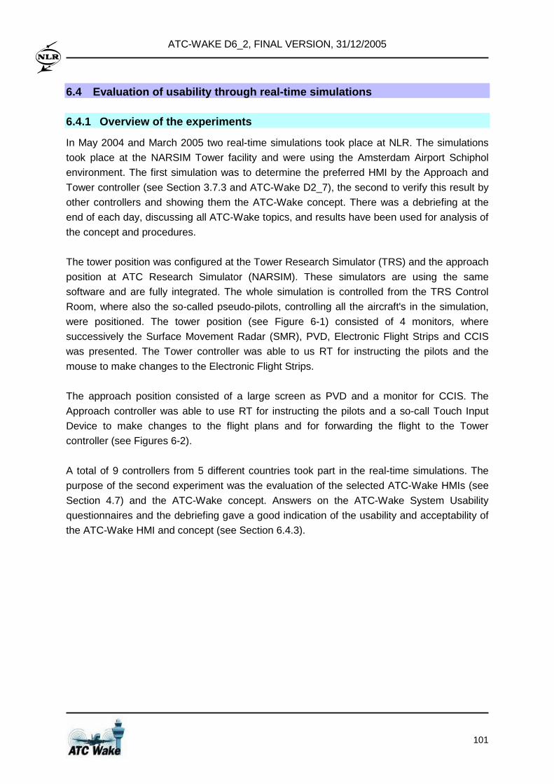
ATC-WAKE D6_2, FINAL VERSION, 31/12/2005
101
6.4 Evaluation of usability through real-time simul ations 6.4.1 Overview of the experiments
In May 2004 and March 2005 two real-time simulations took place at NLR. The simulations
took place at the NARSIM Tower facility and were using the Amsterdam Airport Schiphol
environment. The first simulation was to determine the preferred HMI by the Approach and
Tower controller (see Section 3.7.3 and ATC-Wake D2_7), the second to verify this result by
other controllers and showing them the ATC-Wake concept. There was a debriefing at the
end of each day, discussing all ATC-Wake topics, and results have been used for analysis of
the concept and procedures.
The tower position was configured at the Tower Research Simulator (TRS) and the approach
position at ATC Research Simulator (NARSIM). These simulators are using the same
software and are fully integrated. The whole simulation is controlled from the TRS Control
Room, where also the so-called pseudo-pilots, controlling all the aircraft's in the simulation,
were positioned. The tower position (see Figure 6-1) consisted of 4 monitors, where
successively the Surface Movement Radar (SMR), PVD, Electronic Flight Strips and CCIS
was presented. The Tower controller was able to us RT for instructing the pilots and the
mouse to make changes to the Electronic Flight Strips.
The approach position consisted of a large screen as PVD and a monitor for CCIS. The
Approach controller was able to use RT for instructing the pilots and a so-call Touch Input
Device to make changes to the flight plans and for forwarding the flight to the Tower
controller (see Figures 6-2).
A total of 9 controllers from 5 different countries took part in the real-time simulations. The
purpose of the second experiment was the evaluation of the selected ATC-Wake HMIs (see
Section 4.7) and the ATC-Wake concept. Answers on the ATC-Wake System Usability
questionnaires and the debriefing gave a good indication of the usability and acceptability of
the ATC-Wake HMI and concept (see Section 6.4.3).
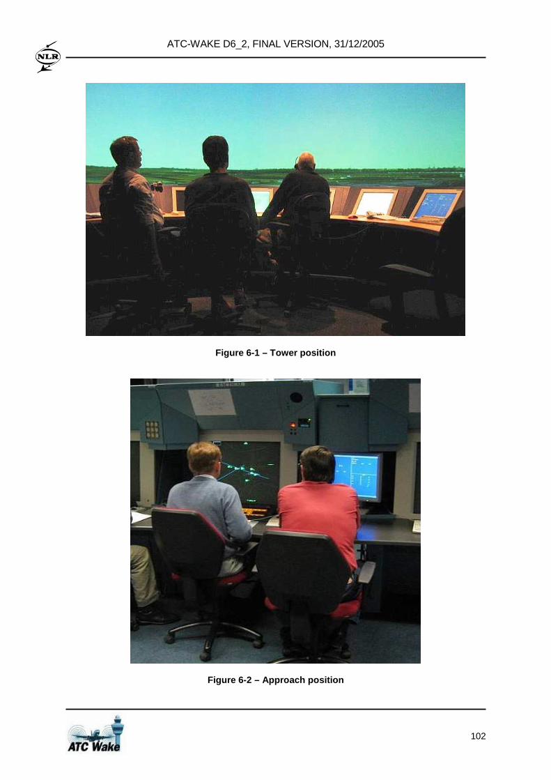
ATC-WAKE D6_2, FINAL VERSION, 31/12/2005
102
Figure 6-1 – Tower position
Figure 6-2 – Approach position
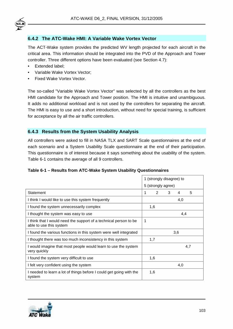
ATC-WAKE D6_2, FINAL VERSION, 31/12/2005
103
6.4.2 The ATC-Wake HMI: A Variable Wake Vortex Vect or
The ACT-Wake system provides the predicted WV length projected for each aircraft in the
critical area. This information should be integrated into the PVD of the Approach and Tower
controller. Three different options have been evaluated (see Section 4.7):
• Extended label;
• Variable Wake Vortex Vector;
• Fixed Wake Vortex Vector.
The so-called "Variable Wake Vortex Vector" was selected by all the controllers as the best
HMI candidate for the Approach and Tower position. The HMI is intuitive and unambiguous.
It adds no additional workload and is not used by the controllers for separating the aircraft.
The HMI is easy to use and a short introduction, without need for special training, is sufficient
for acceptance by all the air traffic controllers.
6.4.3 Results from the System Usability Analysis
All controllers were asked to fill in NASA TLX and SART Scale questionnaires at the end of
each scenario and a System Usability Scale questionnaire at the end of their participation.
This questionnaire is of interest because it says something about the usability of the system.
Table 6-1 contains the average of all 9 controllers.
Table 6-1 – Results from ATC-Wake System Usability Questionnaires
1 (strongly disagree) to
5 (strongly agree)
Statement 1 2 3 4 5
I think I would like to use this system frequently 4,0
I found the system unnecessarily complex 1,6
I thought the system was easy to use 4,4
I think that I would need the support of a technical person to be able to use this system
1
I found the various functions in this system were well integrated 3,6
I thought there was too much inconsistency in this system 1,7
I would imagine that most people would learn to use the system very quickly
4,7
I found the system very difficult to use 1,6
I felt very confident using the system 4,0
I needed to learn a lot of things before I could get going with the system
1,6
ATC-WAKE D6_2, FINAL VERSION, 31/12/2005
104
6.4.4 Conclusions of Real Time Simulations
The conclusions of the simulation are very promising. There is no contradiction between the
debriefing, questionnaire and observations. The ATC-Wake concept and system is easy to
understand and to work with. Controllers appreciate the Wake vortex vector behind an
aircraft, because this is the first time that what they already "know" about the behaviour of
Wake vortices is visualised. Further findings are:
• Transition between ICAO-mode and ATC-Wake mode is not really an issue according to
the controllers, because they are already used to such changes. A system displaying the
Wake Vortex 24 hours a day would be very helpful and eliminate the transition between
ICAO and ATC-Wake mode. The controller should be instructed at the beginning of its
shift to look what the separation criteria are and when these will change.
• Separation of aircraft at 2.5 NM on ILS is sometimes difficult; it seems that the "style" of
the controller (especially the Approach controller), has influence on the performance. The
"style" is a combination of how the controller has learned to control (this differs between
airports) and the capacity demand he/she is used to handle. Some Approach controllers
are not able to "deliver" the aircraft at 2.5 NM.
• When an Approach controller is informed about the wind condition and 2.5 Nm
separation, he/she generally makes the distance between a heavy and medium weight
category aircraft somewhat larger, in anticipation of the fact that a heavy aircraft needs
more time to leave the runway. When an Approach controller is instructed to apply 2.5
Nm separation for all aircraft, the workload of controllers and the number of go-arounds
increases noticeable. The increase of go arounds is related to the fact that the time
between the heavy clearing the runway and the other waiting for landing clearance
becomes smaller. Also, there appears to be a dependency on the location of the exits of
the runway. The increase in workload is less expected, because the traffic load of both
simulation runs is identical. It appears that controllers use the prescribed ATC-Wake
separation as minimum.
• To make optimal use of the ATC-Wake concept (2.5 Nm separation for arrivals),
controllers should be trained to handle the shorter separation, and the somewhat higher
traffic load (this applies especially to the Approach controller).
• During introduction of the ATC-Wake concept, controllers and pilots need to be
convinced that the smaller separation for arrivals and departures are safe to use.
6.5 Airport and airspace simulations 6.5.1 Aim of the fast-time simulations
The aim of the ATC-WAKE fast-time simulations (with TAAM) has been to assess the
potential benefits relating to capacity-efficiency of the considered airport as well as the
potential cost-savings for airlines that have been identified during the project set-up and to
provide indicators to size such benefits:
ATC-WAKE D6_2, FINAL VERSION, 31/12/2005
105
• Capacity – Efficiency : the application of reduced Wake vortex separation has the
potential to significantly increase the efficiency of arrival or departure movements by the
reduction of (intermediate) delays as well as to increase the maximum number of
movements per runway. • Cost savings for Airlines: savings resulting from aircraft delay absorption or the
increase of airport movements per hour impact significantly on airline costs.
6.5.2 Simulation scenarios and assumptions
The main assumptions made for the initial survey of potential simulations are:
• the correct (pre-determined) separation minimum determined during the planning of
operations is applicable for tactical operations (final approach or take-off);
• requirements associated to ATC-Wake operations (in particular visibility conditions) and
supporting systems are met,no technical failure is introduced during simulation.
• pilots will always comply with the reduction of separation for arrivals or departures.
• no operational error (human)
• the aircraft actual performances are compatible with corresponding TAAM model
The scenarios for fast-time simulations have been built using traffic samples from Paris –
Charles de Gaulle for arrival and departure movements. Such traffic sample has been
modified to introduce the reduced separations between aircraft (distance or time) following
the application of the ATC-Wake operational concept. For arrivals, reduced separation
between aircraft is simulated with three different values:
• 2.5 NM for all traffic in a sequence
• 3 NM for all traffic in a sequence
• 4 NM only between:
• Heavy followed by Medium/Light
• Medium followed by Light.
• ICAO standard separation otherwise
For departures, reduced separation between aircraft, for all traffic in a sequence, was
simulated with 3 different values:
• 60 seconds;
• 90 seconds;
• 120 seconds.
In addition 2 scenarios combining arrival and departure traffic have been identified, taking
into account runway crossing, ground movements and a transition in ATC-WAKE separation
mode (from reduced separations to ICAO standard separation and vice versa). The switch
between these two modes of aircraft separation was enabled by a transition plan. The traffic
sample used was collected from CFMU data, and included 1486 movements at the 26th of
ATC-WAKE D6_2, FINAL VERSION, 31/12/2005
106
June 2003 for Paris Charles de Gaulle (CdG) inbound and outbound traffic. In total 3 hours of
traffic was simulated (from 5 am to 8 am UTC). A full description of the traffic samples used
and adaptations made to facilitate assessment of the capacity benefits of ATC-Wake is given
in [D4_7].
6.5.3 Main results from the fast-time simulations
The fast time simulations allowed measuring the impact of reduced separations applied for
both departures and arrivals, in particular to measure the potential increase of number of
movements per hour and the reduction of the average delay per aircraft for the approach
phase or the taxi phase. The simulation results showed different results for arrivals and
departures. The main results are summarised in the following.
For arrivals, the reduction of separation leads indeed to an increase of the number of
landings per hour of in between 1 and 16 extra landings. This potentially represents a 34%
runway throughput increase. The application of reduced separations implied as well the
reduction of arrival delays by 13 minutes over three hours (reduction of the time of the
approach phase). It should be noted that the Runway Occupancy Time (ROT) was not
considered as a limiting factor in the simulations. This should be compared with fuel
consumption figures in order to draw the cost savings for airlines.
For departures , the application of reduced separation modes also showed significant
benefits in terms of run way throughput and delays. 120 seconds separation mode
(equivalent to the current ICAO separation minimum for 2 Medium aircraft) could be
considered valuable, either in terms of number of movements per hour with an increase of
8%, or in terms of delays with a decrease of the average delay of 18%. However, it is noted
that these values are directly related to the distribution of traffic in the sample used (20% of
Heavy in the traffic sample).
From the delay point of view the application of the same (reduced) separation time between
aircraft, independently of the aircraft category, will have a positive effect on delays, i.e. an
decrease of 30s of the separation time results in an increase of 13 minutes of the average
delay per aircraft (per hour).
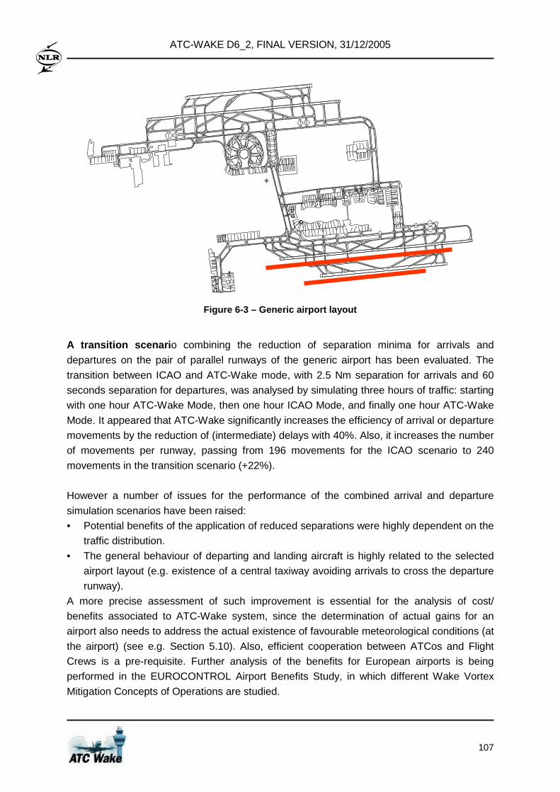
ATC-WAKE D6_2, FINAL VERSION, 31/12/2005
107
Figure 6-3 – Generic airport layout
A transition scenari o combining the reduction of separation minima for arrivals and
departures on the pair of parallel runways of the generic airport has been evaluated. The
transition between ICAO and ATC-Wake mode, with 2.5 Nm separation for arrivals and 60
seconds separation for departures, was analysed by simulating three hours of traffic: starting
with one hour ATC-Wake Mode, then one hour ICAO Mode, and finally one hour ATC-Wake
Mode. It appeared that ATC-Wake significantly increases the efficiency of arrival or departure
movements by the reduction of (intermediate) delays with 40%. Also, it increases the number
of movements per runway, passing from 196 movements for the ICAO scenario to 240
movements in the transition scenario (+22%).
However a number of issues for the performance of the combined arrival and departure
simulation scenarios have been raised:
• Potential benefits of the application of reduced separations were highly dependent on the
traffic distribution.
• The general behaviour of departing and landing aircraft is highly related to the selected
airport layout (e.g. existence of a central taxiway avoiding arrivals to cross the departure
runway).
A more precise assessment of such improvement is essential for the analysis of cost/
benefits associated to ATC-Wake system, since the determination of actual gains for an
airport also needs to address the actual existence of favourable meteorological conditions (at
the airport) (see e.g. Section 5.10). Also, efficient cooperation between ATCos and Flight
Crews is a pre-requisite. Further analysis of the benefits for European airports is being
performed in the EUROCONTROL Airport Benefits Study, in which different Wake Vortex
Mitigation Concepts of Operations are studied.
ATC-WAKE D6_2, FINAL VERSION, 31/12/2005
108
6.6 Evaluation of interoperability with existing AT C systems 6.6.1 Systems affected and introduced
The ATC-Wake system requirements specify four new ATC-Wake components, to be
integrated in the airport environment. It concerns the ATC-Wake Separation Mode Planner,
Predictor, Monitoring and Alert, and the Detector. The implementation effort needed for their
introduction is addressed in Section 7. Existing systems necessary from ATC-Wake point of
view, but for which no changes are needed are: flight data processing systems and
surveillance systems. Some improvements of meteo systems and supervisor HMI are
foreseen. Other ATC systems (meteorological forecast, flight planning and flight information,
and ATCo HMI) to be adapted are described below.
Meteorological Forecast Adequate meteorological forecast data has been identified as a major enabler for the
introduction of ATC-Wake. Existing meteorological systems for the aerodrome environment
offer a limited set of information concerning current wind, temperature, and visibility
conditions as well as tendencies. ATC-Wake operations require a number of supplementary
atmospheric sensing systems, such as wind profilers or temperature profilers, which provide
more accurate meteorological information (possibly even complemented by a specific
forecasting system).
Flight Planning and Flight Information The application of reduced separation in aerodrome operations requires changes to existing
systems used for the planning of arrivals. When a change of the Separation Mode (ICAO or
ATC-Wake) is decided, this shall be communicated to an Arrival Manager (AMAN), which
updates accordingly the timing of the approach phase (time over initial approach fix, landing
time) for each individual flight.
Human Machine Interface (HMI) The HMI of ATC Controllers needs to be updated for the introduction of Wake vortex
separation mode, and Wake vortex prediction and detection information (displayed as Wake
vortex vector and alerts). From a survey conducted by EUROCONTROL, it can be concluded
that currently only one of the participating airports has an operational arrival manager and no
airport has an automated tool for sequencing the take-off movements. The same survey also
addressed the (current) organisation of ATC services for approach and aerodrome
operations. The results show that the ATC-Wake actor/responsibility decomposition:
• Matches with existing job descriptions for the following actors: ATC/Tower Supervisor,
the Initial/Intermediate Approach Controller, the Tower and the Ground Controller.
• Matches with the Arrival Sequence Manager (ASM) function at airports London -
Heathrow, London – Gatwick, and Paris – Orly (at the other 7 investigated airports there
is no ASM).
ATC-WAKE D6_2, FINAL VERSION, 31/12/2005
109
6.6.2 Impact on current CONOPS
The main change implied by ATC-Wake (as compared with the current operational
procedures) is the transition from the fixed Wake vortex separation minima defined by ICAO
to the ATC-Wake separation minima, which is updated regularly (with at least a 40 minutes
pre-notice). From the ATC controller perspective such transition can be compared with a
runway configuration change (e.g. from west to east configuration) and therefore does not
represent a revolution for aerodrome operations.
Another significant change is the issue of Wake vortex related alerts (indicating the potential
risk of a Wake vortex encounter) by the ATC-Wake system. Such alerts do not exist in the
today operational procedures. Nevertheless, during the final approach operations, the main
actions required for ATC controllers will be limited to informing the pilot and supporting
his/her decision (i.e. to continue the approach or initiate a missed approach) by providing
guidance and/or separation with other traffic.
6.6.3 Impact of ATC-Wake on arrival and departure m anagement
To improve efficiency, airports are introducing arrival manager and departure manager tools
(so called AMAN and DMAN). These tools use the ICAO separation criteria as basis to
determine the optimal arrival and departure sequence. During ATC-Wake mode other
separation criteria are applied and by means of an analytical study an indication about the
impact of ATC-Wake mode on both tools has been assessed. The following has shown when
the ATC-Wake mode is compared with the ICAO mode:
• The arrival capacity increases significantly when changing from standard ICAO Wake
vortex separations to ATC-Wake mode separations.
• The departure capacity increases significantly when changing from standard ICAO Wake
vortex separations to ATC-Wake mode separations.
• The average arrival delay decreases significantly when changing from standard ICAO
operations to ATC-Wake mode for the same demand level.
6.7 Assessment of ATC-Wake Operational Feasibility
The assessment of operational feasibility for the implementation of ATC-WAKE operational
concept within Europe has been performed along several axis: • Correctness, usability and acceptability of the operational concept by ATC
Controllers: the operational concept is not a ‘revolution’ for ATC, it represents a sound
evolution from existing procedures (runway configuration and transition).
The real-time simulations performed by NLR indicates that the ATC-WAKE concept of
operations has been easily adopted by a team of ATC Controllers and positive feed-back
for its use in operations has been received.
ATC-WAKE D6_2, FINAL VERSION, 31/12/2005
110
In addition the size of the changes from operational perspective (airport infrastructure,
training) fits with the existing evolutions observed at European airports to cope with the
increasing traffic demand.
• Operational benefits : the fast-time simulations have allowed to assess the potential
gains for runway throughput and flight times considering a number of potential scenarios
for the reduction of minimum separation (distance or time) and the runway usage (arrivals
only, departures only, mixed mode). The potential gains following the application of
reduced separation are significant, varying between 10% and 30% increase of runway
throughput and between 10% and 40% reduction of the average delay per flight.
However the actual gains will be dependent on a number of factors:
• Favourable meteorological conditions: the transport of Wake vortex out of the arrival
or departure corridors is observed when a significant and persistent cross-wind exists
and to take benefit out of such situation a minimum 20min reliable wind forecast is
necessary to plan traffic. In addition good visibility conditions are required for reduced
separation operations;
• Traffic pressure: the application of reduced separation operations will deliver benefits
only when a high level of traffic exists and sufficient notice is made to ATC to plan
aircraft movements accordingly;
• Traffic distribution: potential benefits of the application of reduced separations are
highly dependent on the traffic distribution;
• Airport layout: the general behaviour of departing and landing aircraft is highly related
to the selected airport layout (e.g. existence of a central taxiway avoiding arrivals to
cross the departure runway) • Impact on existing ATC systems : the analysis of interoperability issues has confirmed
that the main changes to systems concern the implementation of specific atmospheric
sensing systems (e.g. weather radar or LIDAR), the introduction of ATC-WAKE tools for
ATC (separation mode planning, Wake vortex prediction, detection and monitoring tools). The impact on existing systems is low, mainly the arrival management tool (AMAN)
requires modification to support the fluent transitioning between ATC-WAKE reduced
separations and standard ICAO separations (depending on meteorological conditions).
As a main conclusion the ATC-WAKE operational feasibility analysis has allowed to build
confidence in the proposed operational concept for the application of reduced separations to
represent a sound evolution from existing ATC procedures and working practices, to deliver
significant benefits for runway throughput and average delay per flight without major rework
to the current ATC systems.
Nevertheless such positive conclusions on operational feasibility will need to be traded-off
against the actual weather ‘windows’ to perform such operations and the costs for the
acquisition and implementation of the new equipments or infrastructure required (Wake
vortex sensors, new atmospheric sensing systems, enhanced weather forecast capabilities).
ATC-WAKE D6_2, FINAL VERSION, 31/12/2005
111
7 Technological Implementation Plan
7.1 Introduction
The main exploitable project output is the ATC Wake Integrated Platform (IP), which contains
as further new exploitable ATC-Wake results:
• ATC-Wake Separation Mode Planner
• ATC-Wake Predictors
• ATC-Wake Monitoring and Alerts
• ATC-Wake Detectors
• Air Traffic Controller Human Machine Interfaces (HMIs).
The ATC-Wake Integrated Platform (IP) has been built using SPINEware middleware
technology, which provides an integrated view on an heterogeneous network of different
computer platforms enabling access to the different subsystems and tools of the different
partners. The IP is presented to users (research and development centres and industrial
organisations) as a user-centred working environment, and comprises all the designed and
implemented interfaces between the subsystems and tools of the individual partners. The
Intellectual Property Rights (IPRs) of these individual subsystems and tools are described in
ATC-Wake D5_1 (Dissemination & Use Plan). The ATC-Wake Integrated Platform has been
designed, specified, and implemented, and all four new components (Separation Mode
Planner, Predictor, Monitoring and Alerts, and Detectors) and their interfaces have been built
and tested. Already existing subsystems and tools have been upgraded following the
definition of the operational requirements, operational concept, users requirements and
system requirements.
The ATC-Wake IP has been demonstrated at the ATC-Wake User Group Meeting and the
EC Review Meeting on 7/8 April 2005 at the site of UCL, near Brussels. A further trial took
place at the ATC-Wake Final Meeting, again with the ATC-Wake User Group. Participating
air-traffic controllers were directly involved in selecting the best method for on-screen display
of aircraft position and Wake vortex information.
The ATC-Wake platform will enable European ATS providers, airport authorities, and ATM
research and development centres to join their efforts (and plan their investments) to
adequately adapt their airport systems and enhance the efficient use of airports restricted by
the Wake vortex problem. In this sense ATC-WAKE is a key enabler of the European ATM
strategy for the years 2000+ ; Wake Vortex is included in the Single European Sky ATM
Masterplan activities (joint Eurocontrol/EC SESAME project). ATC-Wake is also included in
the EUROCONTROL Wake Vortex Separations Management Plan and the
FAA/EUROCONTROL Action Plan 14 on Wake Vortex.
ATC-WAKE D6_2, FINAL VERSION, 31/12/2005
112
Besides direct application of the ATC-Wake results and outputs, two follow-up European
Research and Development projects are foreseen before actual capacity increase at airports
can be realised:
• CREDOS (or CROWS) : elaboration & testing of an operational concept for crosswind
departures through real-time ATC simulations, Wake vortex data collection and analysis,
risk assessment, construction of a safety case and human factors case, and a WV safety
management system. • ATC-Wake2 : installation and testing of an ATC-Wake system at selected airport(s),
through shadow-mode field trials and evaluation of the experiences with the new working
methods. The EC/IST recommends that this will be done as an integrated project
(together with I-Wake & TALIS). Therefore, results from I-Wake and their possible use
will be discussed in some more detail in Section 7.2
7.2 Broad dissemination and use
The ATC-Wake Public Reports and associated technical publications will be placed on the
ATC-Wake and WakeNet Europe public web-sites and will be distributed by e-mail to the
WakeNet 2 Europe and WakeNet USA communities. Dissemination of project results has
been achieved through presentations at conferences and publications (publications and
presentations resulting fully or partly from the ATC-Wake project and listed in the reference
list). The ATC-Wake Concept of Operations was presented by the European Wake Vortex
Conops development team in parallel with the US team who work on a similar concept
WakeVAS. A user group has been formally involved within ATC-Wake, and has been
consulted throughout the project: two ATS providers (NATS and DFS), the European
Association of Aerospace Industries (ASD), one aircraft manufacturer (Airbus), one ATM
development center (NASA), the cooperative effort between the European and US ATM
authorities (FAA/EUROCONTROL), and Canadian ATM organizations (Transport Canada
and Nav Canada). The outcomes of the study have the following application areas:
Installation and use of ATC-Wake system for reduced separation at airports For airports operating near their maximum throughput limits dynamic (weather dependent)
Wake vortex separation rules may lead to a substantial decrease in average delay time and
large potential economic savings. Potential gains will depend on the traffic mix, the prevailing
weather climatology at the particular airport and the available run-way topology. Essential
new elements for installation of an operational system with dynamic (weather dependent)
separation rules at an airport are the four ATC-Wake components: Separation Mode Planner,
Predictor, Monitoring and Alert, and Detector, as well as the new ATCo Human Machine
Interfaces, which have been tested at the NLR ATC research simulators. Crosswinds and
strong headwinds are candidates to be used in dynamic weather dependent Separation
Mode Planning. It is noted that results from S-Wake have been used to assess appropriate
reduced separation minima for a variety of aircraft operating at airports with ATC-Wake.
ATC-WAKE D6_2, FINAL VERSION, 31/12/2005
113
Possible harmonization and re-definition of Wake vo rtex separation rules The current arrival separation rules define separation minima depending on the MTOW of
the paired aircraft. At present different countries apply somewhat different rules for the
separation minima. ATC-Wake outcomes and tools can also be used for assessing the Wake
vortex safety and capacity implications of new Wake vortex operational concepts, based on a
different ruling (dynamic weather based separation instead of static separation rules). In this
respect, it is noted that EUROCONTROL has recently completed an Airports Benefits Study,
in which airport capacity enhancements of 3 new Wake Vortex Concepts of Operations
(ATC-Wake, Crosswind Departures, and Time Based Separation) for major European
airports have been estimated.
Safety and capacity improvements with a Very Large Transport Aircraft (VLTA) The tools developed in ATC-Wake can also be used to compare the levels of safety of a
future Very Large Transport Aircraft (VLTA) with current very heavy aircraft, when operating
at an airport with an ATC-Wake system in use (provided the Wake characteristics of the
VLTA are known, and also made available). The ATC-Wake tools used for analysis of the
capacity aims and expected improvements can also be used to evaluate the capacity
enhancements when a new VLTA operates at an airport with an ATC-Wake system. For all
such safety and capacity assessments it is expected that local weather and Wake data will
be needed to build the safety case.
7.3 Ground based Wake prediction, monitoring, alert ing capabilities
Which meteorological parameters have to be measured and/or forecasted for Wake vortex
warning systems and for (weather dependent) safety assessments? Mean wind (all three
wind components) and wind variability, turbulence, virtual potential temperature and vertical
wind shear are all known to influence the Wake development. However, some of these
parameters are difficult or impossible to forecast or even to measure. Therefore, one might
tailor specific solutions for specific applications. For example, a cross-wind now-casting
system for aircraft departures requires to observe and to forecast only a minimum set of
parameters, such as the horizontal wind components and associated temporal and spatial
variability, for a short time horizon on the order of 10 minutes. For the arrival concept of
operation, a longer time horizon of at least 40 minutes is required to enable arrival
sequencing.
Another approach relies on observation combined with statistics collected at the airfield
where the quantity of the measured parameter is assumed to persist (or to vary slowly) in
time with growing uncertainty allowances as the forecast lead time proceeds. The time
horizon for that method is maximum one hour. As such it is of importance to enhance the
quality of the forecasting algorithms. It is recommended to further develop test algorithms for
an optimum fusion of observation and forecast data in order to obtain best-guess fields of
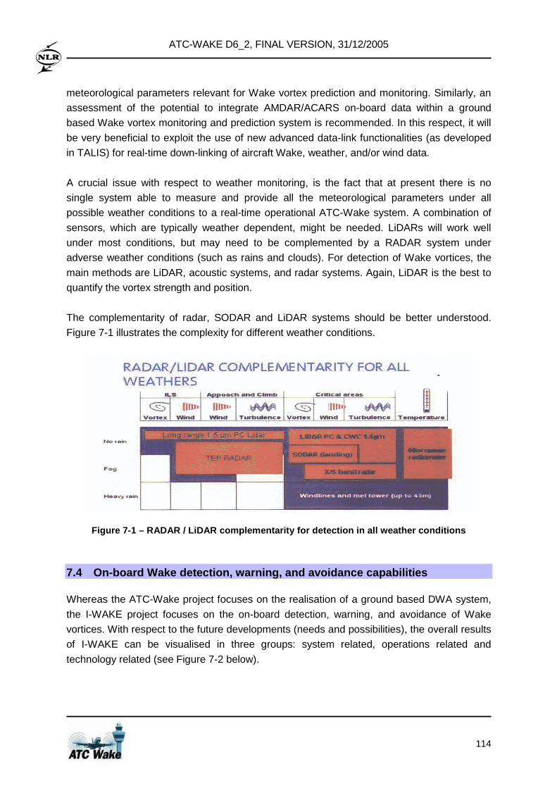
ATC-WAKE D6_2, FINAL VERSION, 31/12/2005
114
meteorological parameters relevant for Wake vortex prediction and monitoring. Similarly, an
assessment of the potential to integrate AMDAR/ACARS on-board data within a ground
based Wake vortex monitoring and prediction system is recommended. In this respect, it will
be very beneficial to exploit the use of new advanced data-link functionalities (as developed
in TALIS) for real-time down-linking of aircraft Wake, weather, and/or wind data.
A crucial issue with respect to weather monitoring, is the fact that at present there is no
single system able to measure and provide all the meteorological parameters under all
possible weather conditions to a real-time operational ATC-Wake system. A combination of
sensors, which are typically weather dependent, might be needed. LiDARs will work well
under most conditions, but may need to be complemented by a RADAR system under
adverse weather conditions (such as rains and clouds). For detection of Wake vortices, the
main methods are LiDAR, acoustic systems, and radar systems. Again, LiDAR is the best to
quantify the vortex strength and position.
The complementarity of radar, SODAR and LiDAR systems should be better understood.
Figure 7-1 illustrates the complexity for different weather conditions.
Figure 7-1 – RADAR / LiDAR complementarity for dete ction in all weather conditions
7.4 On-board Wake detection, warning, and avoidance capabilities
Whereas the ATC-Wake project focuses on the realisation of a ground based DWA system,
the I-WAKE project focuses on the on-board detection, warning, and avoidance of Wake
vortices. With respect to the future developments (needs and possibilities), the overall results
of I-WAKE can be visualised in three groups: system related, operations related and
technology related (see Figure 7-2 below).
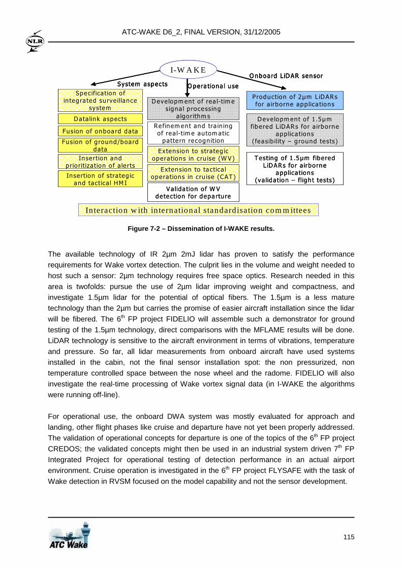
ATC-WAKE D6_2, FINAL VERSION, 31/12/2005
115
I-W A K EOnboard L iDAR sensor
System aspects Opera tional use
Production of 2µm L iDARsfor a irborne app lica tions
Development o f 1 .5µm fibered L iDARs for a irborne
applica tions(feasib ility – ground tests)
Testing of 1 .5µm fibered L iDARs for a irborne
applica tions(va lidation – flight tests)
Development o f rea l-tim e signa l p rocessing
a lgorithm s
Refinem ent and tra in ing of rea l-tim e autom atic
patte rn recogn ition
Extension to strateg ic operations in cru ise (WV)
Extension to tactica l operations in cru ise (CAT)
Va lida tion of W V detection for departure
Specification o f in tegrated surve illance
system
Data link aspects
Fusion of onboard data
Fusion of g round/board data
Insertion andprioritization o f a lerts
Insertion of strateg ic and tactica l HM I
In teraction w ith in ternational standardisation com mittees
I-W A K EOnboard L iDAR sensor
System aspects Opera tional use
I-W A K EOnboard L iDAR sensor
System aspects Opera tional use
Production of 2µm L iDARsfor a irborne app lica tions
Development o f 1 .5µm fibered L iDARs for a irborne
applica tions(feasib ility – ground tests)
Testing of 1 .5µm fibered L iDARs for a irborne
applica tions(va lidation – flight tests)
Development o f rea l-tim e signa l p rocessing
a lgorithm s
Refinem ent and tra in ing of rea l-tim e autom atic
patte rn recogn ition
Extension to strateg ic operations in cru ise (WV)
Extension to tactica l operations in cru ise (CAT)
Va lida tion of W V detection for departure
Specification o f in tegrated surve illance
system
Data link aspects
Fusion of onboard data
Fusion of g round/board data
Insertion andprioritization o f a lerts
Insertion of strateg ic and tactica l HM I
In teraction w ith in ternational standardisation com mittees
Figure 7-2 – Dissemination of I-WAKE results.
The available technology of IR 2µm 2mJ lidar has proven to satisfy the performance
requirements for Wake vortex detection. The culprit lies in the volume and weight needed to
host such a sensor: 2µm technology requires free space optics. Research needed in this
area is twofolds: pursue the use of 2µm lidar improving weight and compactness, and
investigate 1.5µm lidar for the potential of optical fibers. The 1.5µm is a less mature
technology than the 2µm but carries the promise of easier aircraft installation since the lidar
will be fibered. The 6th FP project FIDELIO will assemble such a demonstrator for ground
testing of the 1.5µm technology, direct comparisons with the MFLAME results will be done.
LiDAR technology is sensitive to the aircraft environment in terms of vibrations, temperature
and pressure. So far, all lidar measurements from onboard aircraft have used systems
installed in the cabin, not the final sensor installation spot: the non pressurized, non
temperature controlled space between the nose wheel and the radome. FIDELIO will also
investigate the real-time processing of Wake vortex signal data (in I-WAKE the algorithms
were running off-line).
For operational use, the onboard DWA system was mostly evaluated for approach and
landing, other flight phases like cruise and departure have not yet been properly addressed.
The validation of operational concepts for departure is one of the topics of the 6th FP project
CREDOS; the validated concepts might then be used in an industrial system driven 7th FP
Integrated Project for operational testing of detection performance in an actual airport
environment. Cruise operation is investigated in the 6th FP project FLYSAFE with the task of
Wake detection in RVSM focused on the model capability and not the sensor development.
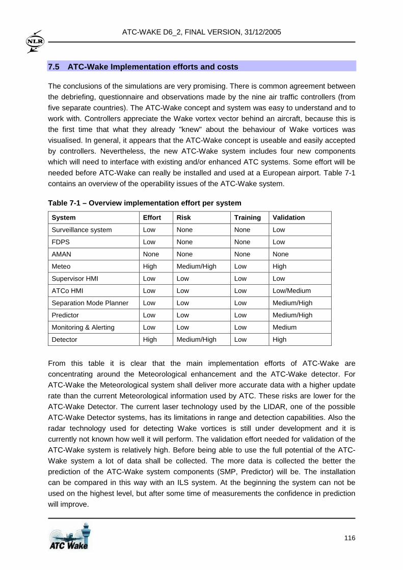
ATC-WAKE D6_2, FINAL VERSION, 31/12/2005
116
7.5 ATC-Wake Implementation efforts and costs
The conclusions of the simulations are very promising. There is common agreement between
the debriefing, questionnaire and observations made by the nine air traffic controllers (from
five separate countries). The ATC-Wake concept and system was easy to understand and to
work with. Controllers appreciate the Wake vortex vector behind an aircraft, because this is
the first time that what they already "knew" about the behaviour of Wake vortices was
visualised. In general, it appears that the ATC-Wake concept is useable and easily accepted
by controllers. Nevertheless, the new ATC-Wake system includes four new components
which will need to interface with existing and/or enhanced ATC systems. Some effort will be
needed before ATC-Wake can really be installed and used at a European airport. Table 7-1
contains an overview of the operability issues of the ATC-Wake system.
Table 7-1 – Overview implementation effort per syst em
System Effort Risk Training Validation
Surveillance system Low None None Low
FDPS Low None None Low
AMAN None None None None
Meteo High Medium/High Low High
Supervisor HMI Low Low Low Low
ATCo HMI Low Low Low Low/Medium
Separation Mode Planner Low Low Low Medium/High
Predictor Low Low Low Medium/High
Monitoring & Alerting Low Low Low Medium
Detector High Medium/High Low High
From this table it is clear that the main implementation efforts of ATC-Wake are
concentrating around the Meteorological enhancement and the ATC-Wake detector. For
ATC-Wake the Meteorological system shall deliver more accurate data with a higher update
rate than the current Meteorological information used by ATC. These risks are lower for the
ATC-Wake Detector. The current laser technology used by the LIDAR, one of the possible
ATC-Wake Detector systems, has its limitations in range and detection capabilities. Also the
radar technology used for detecting Wake vortices is still under development and it is
currently not known how well it will perform. The validation effort needed for validation of the
ATC-Wake system is relatively high. Before being able to use the full potential of the ATC-
Wake system a lot of data shall be collected. The more data is collected the better the
prediction of the ATC-Wake system components (SMP, Predictor) will be. The installation
can be compared in this way with an ILS system. At the beginning the system can not be
used on the highest level, but after some time of measurements the confidence in prediction
will improve.
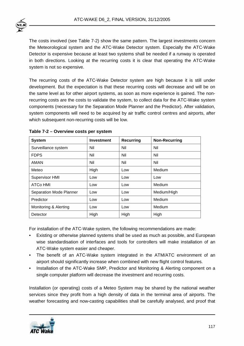
ATC-WAKE D6_2, FINAL VERSION, 31/12/2005
117
The costs involved (see Table 7-2) show the same pattern. The largest investments concern
the Meteorological system and the ATC-Wake Detector system. Especially the ATC-Wake
Detector is expensive because at least two systems shall be needed if a runway is operated
in both directions. Looking at the recurring costs it is clear that operating the ATC-Wake
system is not so expensive.
The recurring costs of the ATC-Wake Detector system are high because it is still under
development. But the expectation is that these recurring costs will decrease and will be on
the same level as for other airport systems, as soon as more experience is gained. The non-
recurring costs are the costs to validate the system, to collect data for the ATC-Wake system
components (necessary for the Separation Mode Planner and the Predictor). After validation,
system components will need to be acquired by air traffic control centres and airports, after
which subsequent non-recurring costs will be low.
Table 7-2 – Overview costs per system
System Investment Recurring Non-Recurring
Surveillance system Nil Nil Nil
FDPS Nil Nil Nil
AMAN Nil Nil Nil
Meteo High Low Medium
Supervisor HMI Low Low Low
ATCo HMI Low Low Medium
Separation Mode Planner Low Low Medium/High
Predictor Low Low Medium
Monitoring & Alerting Low Low Medium
Detector High High High
For installation of the ATC-Wake system, the following recommendations are made:
• Existing or otherwise planned systems shall be used as much as possible, and European
wise standardisation of interfaces and tools for controllers will make installation of an
ATC-Wake system easier and cheaper.
• The benefit of an ATC-Wake system integrated in the ATM/ATC environment of an
airport should significantly increase when combined with new flight control features.
• Installation of the ATC-Wake SMP, Predictor and Monitoring & Alerting component on a
single computer platform will decrease the investment and recurring costs.
Installation (or operating) costs of a Meteo System may be shared by the national weather
services since they profit from a high density of data in the terminal area of airports. The
weather forecasting and now-casting capabilities shall be carefully analysed, and proof that
ATC-WAKE D6_2, FINAL VERSION, 31/12/2005
118
this will meet operational requirements shall be provided. Looking at the other systems, the
following statements can be made:
• No improvements of the existing systems are needed for use of ATC-Wake. All the
functionality for the enhanced systems is mature enough to start field trials.
• The ATC-Wake SMP and Predictor systems are mature enough and deliver the
functionalities needed for ATC-Wake. The ATC-Wake Monitoring & Alerting system can
be used as is, but fine-tuning and training of the alarm functionality might be needed
(through shadow-mode field trails or real-time simulations).
• The ATC-Wake Detector system needs improvement (see also Section 7.3) and is also
relatively expensive. The performance of a LIDAR system as stand-alone Detector is too
limited. The ATC-Wake detector system shall be able to assess strength/position of the
Wake vortex behind an aircraft with sufficient accuracy.
• The quality of weather forecasting and nowcasting can be enhanced by more frequent
updates of the initial and boundary conditions provided as input.
7.6 Economic development and further exploitation
The work performed in ATC-Wake contributes directly to several objectives of the EC Information Society Technologies (IST) Programme for creating a User Friendly
Information Society. For Key Action I – Systems and services for the Citizen , the project
addresses objective I.5 Transport and Tourism by developing and building an integrated
ATC Wake vortex safety and capacity platform with the aim to improve safety. This allows
more efficient and comfortable transport, resulting in airport capacity increase. Research is
focused on sub-task I.5.2 Integrated vehicle infrastructure systems which aims to improve
safety, security, comfort and efficiency in all modes of passenger and freight transport and to
improve mobility management, through more interaction between in-vehicle systems and
infrastructure systems (transport, navigation, communication, etc.). In this sense, the ATC-
Wake platform might be used by ATS providers, airport authorities, ATM industry, and ATM
research and development centres to facilitate their efforts in the search process to adequate
solutions to the Wake vortex problem. From the industrial viewpoint the platform is a
necessary building block to build up such a new ATC system at European airports.
Each organisation has developed its own plans for exploitation of its results, because each
organisation has its own exploitation objectives. The research institutes and ATM research
and development centre will exploit results by transferring knowledge to industry, all players
in the Air Traffic Management world (e.g. airports, ATS providers, policy makers, air traffic
controllers, pilots) and enhancing their capabilities for competing for similar national and EU
funded projects. The university will exploit the project along education (enhancing courses
offered by them in subjects related to the project objectives, and research (enhancing the
capabilities for competing for similar national and EU projects). Finally, industry will exploit
the results by developing the designed platform further towards the integrated ATC system
ATC-WAKE D6_2, FINAL VERSION, 31/12/2005
119
operational at airports. The detailed plans for exploitation of the ATC-Wake main project
results and the plans of the partners are described in ATC-Wake D5_3.
The general scheme for exploitation of results can be synthesised as shown in Table 7-3.
Although the ground based ATC-Wake system architecture will be at the heart of a Wake
vortex prediction and monitoring system that facilitates reduced separation at airports under
favourable wind conditions, it is anticipated that instrumentation for Wake detection on-board
(such as I-Wake) will provide further safety benefits. The architecture of such ground/
airborne system is already under investigation in FLYSAFE; nevertheless operational testing
and shadow mode field trials at an airport are not planned. The best would be an 7th FP
Integrated Project where the newly developed Wake vortex concepts of operations will be
tested through shadow mode field trials, i.e. with direct involvement of airports and Air Traffic
Control centres.
A crucial issue to consider before actual implementation will be possible, is the provision of
sufficient proof that performance requirements will be met. In this respect, it is noted that,
since 2005, the application of the European Operational Concept Validation Methodology (E-
OCVM) and the use of the Validation Data Repository (VDR) is required by all new ATM-
related projects, in particular within the collaboration between the EC and EUROCONTROL
in the ATM Master Plan and also along the ACARE Strategic Research Agenda SRA-2. The
E-OCVM aims to provide a common approach to all projects contributing to the validation of
operational concepts from early identification to full pre-operational validation as a pre-
requisite for industrialisation and operational introduction. A Safety Case, Human Factors
Case, Benefits Case, and a Technology Case will need to be produced before ATC-Wake
can be implemented.
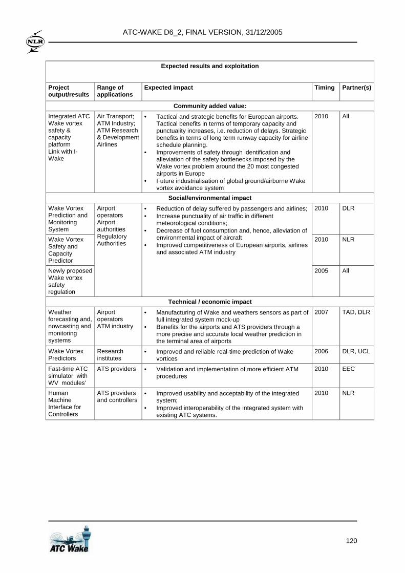
ATC-WAKE D6_2, FINAL VERSION, 31/12/2005
120
Expected results and exploitation
Project output/results
Range of applications
Expected impact Timing Partner(s)
Community added value:
Integrated ATC Wake vortex safety & capacity platform Link with I-Wake
Air Transport; ATM Industry; ATM Research & Development Airlines
• Tactical and strategic benefits for European airports. Tactical benefits in terms of temporary capacity and punctuality increases, i.e. reduction of delays. Strategic benefits in terms of long term runway capacity for airline schedule planning.
• Improvements of safety through identification and alleviation of the safety bottlenecks imposed by the Wake vortex problem around the 20 most congested airports in Europe
• Future industrialisation of global ground/airborne Wake vortex avoidance system
2010 All
Social/environmental impact
Wake Vortex Prediction and Monitoring System
2010 DLR
Wake Vortex Safety and Capacity Predictor
2010 NLR
Newly proposed Wake vortex safety regulation
Airport operators Airport authorities Regulatory Authorities
• Reduction of delay suffered by passengers and airlines; • Increase punctuality of air traffic in different
meteorological conditions; • Decrease of fuel consumption and, hence, alleviation of
environmental impact of aircraft • Improved competitiveness of European airports, airlines
and associated ATM industry
2005 All
Technical / economic impact
Weather forecasting and, nowcasting and monitoring systems
Airport operators ATM industry
• Manufacturing of Wake and weathers sensors as part of full integrated system mock-up
• Benefits for the airports and ATS providers through a more precise and accurate local weather prediction in the terminal area of airports
2007 TAD, DLR
Wake Vortex Predictors
Research institutes
• Improved and reliable real-time prediction of Wake vortices
2006 DLR, UCL
Fast-time ATC simulator with WV modules’
ATS providers • Validation and implementation of more efficient ATM procedures
2010 EEC
Human Machine Interface for Controllers
ATS providers and controllers
• Improved usability and acceptability of the integrated system;
• Improved interoperability of the integrated system with existing ATC systems.
2010 NLR
ATC-WAKE D6_2, FINAL VERSION, 31/12/2005
121
8 Conclusions and recommendations
8.1 Conclusions
The IST project ATC-Wake has developed an integrated platform for ATC (Air Traffic
Control) that will allow variable aircraft separation distances, as opposed to the fixed
distances presently applied at airports. A variety of existing subsystems have been
integrated within the ATC-Wake Integrated Platform (IP), which was used to:
• To evaluate the interoperability of the ATC-Wake system with existing ATC systems
currently used at various European airports;
• To assess the safety and capacity improvements that can be obtained by local
installation of the integrated system at various European airports;
• To evaluate operational usability and acceptability of the ATC-Wake system;
• To make a plan and to assess cost elements for further development, implementation
and exploitation of the ATC-Wake IP (and other results).
This platform is an essential step that will lead to installation of an integrated ATC decision
support system at airports, enabling air traffic controllers to apply new optimised weather
based aircraft separation. The ATC-Wake system integrates weather and Wake sensors,
weather forecasting and now-casting systems, Wake vortex prediction system, separation
mode planner, and air traffic controller interfaces.
WP1: ATC-WAKE OPERATIONAL CONCEPT AND SYSTEM REQUIR EMENTS As a first step towards use of an ATC-Wake system at airports, the operational concept and
requirements for the application of reduced aircraft separation under favourable weather
conditions have been established. During the development and evaluation of the
requirements, a number of key issues have been identified for further analysis:
• Transitions between ATC-Wake and ICAO separation modes;
• Aircraft separation and sector loading;
• Missed approaches when ATC-Wake is applied;
• Evaluation of safety requirements;
• Evaluation of capacity benefits;
• Evaluation of operational feasibility;
• Assessment of the ATC-Wake system performance requirements;
• Potential use of WV instrumentation on-board aircraft (and down-linking of WV data).
During the remainder of ATC-Wake, these issues have been further investigated, and it
appears that there are no major show-stoppers for continuation. However, it has to be
mentioned that sufficiently stable and reliable meteorological forecast/now-cast data and WV
detection information is a prerequisite for safe implementation of ATC-Wake.
ATC-WAKE D6_2, FINAL VERSION, 31/12/2005
122
The reduced Wake Vortex separation, targeted under crosswind conditions, is: • 2.5 Nm separation between all aircraft on the same final approach path • 90 seconds between all aircraft departing on the sa me runway.
WP2: ATC-WAKE SYSTEM DESIGN AND DEVELOPMENT Following the definition of the Operational Concept and System Requirements, WP2 on
System Design and Evaluation has established an Integrated Platform as key intermediate
step before the ATC-Wake system can be installed locally at an airport.
The ATC-Wake Operational System comprises four new components, which interface with
several existing and/or enhanced ATC systems. New ATC-Wake components, together
constituting the Separation Advisory System (SAS), are:
• ATC-Wake Separation Mode Planner
• ATC-Wake Predictor
• ATC-Wake Monitoring and Alerting
• ATC-Wake Detector.
These components have been integrated successfully in the Integrated Platform, and it has
been shown that the functional data flow defined in WP1 on System Requirements for all
ATC-Wake Use Cases (Separation Mode Planning, Transition Phase, Approach Phase, and
Departure Phase) can be realized in an Operational ATC System.
The technical feasibility of the ATC-Wake system has been evaluated by experimental
simulations with the Integrated Platform. It has been shown that the functional integration of
the components is successful and it will be technically feasible to integrate wake vortex
prediction/detection information into existing ATC systems. Air Traffic Controller Human Machine Interfaces have been designed, specified, and
tested successfully through two real-time simulation experiments with nine active controllers
from five European countries. It has been shown that these HMIs are compliant with the
HMIs currently used at key European airports (CdG and Schiphol).
Nevertheless, it should be mentioned that the Software Integration itself appeared to be
much more difficult than anticipated. Furthermore, there are still some key issues that will need to be addressed in more detail before the ATC-Wake system can be installed locally at an airport :
• The ATC-Wake Integrated Platform has been established using SPINEware middle-ware
technology, enabling distributed use of the ATC-Wake components prepared by the
consortium partners and running remotely at different sites. Next step will be to install all
systems together at a single site, and to demonstrate its use in real-time.
ATC-WAKE D6_2, FINAL VERSION, 31/12/2005
123
• The systems available for use as part of the ATC-Wake Detector (e.g. LiDAR and
SODAR systems) meet certain performance requirements. It is not completely clear
whether their accuracy, integrity, and reliability will be sufficient in all weather conditions.
Their complementary use should be better understood (see Section 7).
• The quality of the meteorological forecast (and now-casting) systems might need to be
enhanced allowing frequent updates of the information provided to the ATC-Wake
Separation Mode Planner and the ATC-Wake Predictor.
WP3: POTENTIAL SAFETY AND CAPACITY IMPROVEMENTS As motivation for the use of ATC-Wake, the WP3 on Safety and Capacity Analysis has evaluated the potential safety and capacity improvements. It has been shown that runway throughput and delay improves noticeably when the A TC-Wake system is used .
Depending on the occurrence of favorable crosswind conditions, the increase in runway
throughput is about 2% for the ATC-Wake SRD operation and 5% for the ATC-Wake SRA
operation (at a generic airport with average wind conditions).
Introduction of a new ATC system cannot be done without showing that minimum safety requirements are met . ATC-Wake risk assessments intend to be compliant with ESARR4
requirements posed by EUROCONTROL’s Safety Regulation Unit (SRU). Guidelines for the
development of new wake vortex safety regulation have been given (using a WV risk
management framework developed in S-Wake).
The safety assessment of the ATC-Wake operation has been performed in three steps.
First, as part of the qualitative safety assessment, potential hazards and conflict scenarios
related to use of ATC-Wake have been evaluated. Second, through use of the ‘classical’
WAVIR tool, indicative separation minima dependent on crosswind conditions have been
determined. As these indicative separation minima do not yet account for crosswind
uncertainty, as part of the third step, the setting of requirements for the ATC-Wake system
components was further investigated. It appears that especially the Monitoring and Alerting
system and Meteorological Forecast and Now-casting systems are crucial and sufficient
accuracy and reliability shall be guaranteed.
WAVIR simulations for the SRA operation indicate th at reduced separation of 2.5 Nm can be applied safely in ATC-Wake Mode provided that crosswind is forecasted to be
above a certain limit. During ATC-Wake arrivals, the Monitoring and Alerting component will
anticipate potential wake encounters in time (and generate an alert); nevertheless if the
meteorological forecast information is not accurate and stable enough, this might be
achieved at the cost of a relatively large number of missed approaches. The simulations
indicate that, provided that certain requirements are met, about 30% of the approaches might
be performed with 2.5 Nm aircraft separation in case ATC-Wake is used.
ATC-WAKE D6_2, FINAL VERSION, 31/12/2005
124
WAVIR simulations for the SRD operation also indica te that reduced separation of 90 seconds can be applied safely in ATC-Wake Mode , provided that crosswind is forecasted
to be above a certain limit. If the accuracy of the wind forecast information is too low, the
Monitoring and Alerting component could provide a relatively large number of alerts. A
potential issue is that immediately after take off, i.e. at relatively low altitude, it will not be
feasible for the pilot to turn away from the wake vortex of a preceding aircraft. Provision and
use of meteorological now-casting information by the controller will be very beneficial during
the second departure phase, in order to support the pilot to prepare for a potential encounter
in case of a sudden change of the wind conditions.
Various activities have been performed to validate the safety assessment (including
verification and validation of the wake evolution models, wake encounter models, and aircraft
performance models). Nevertheless, it has become clear that the wake vortex phenomena
during departures is still not fully understood, i.e. further research would be needed before
the outcome of the departure safety assessment will be ready for approval by regulatory
authorities. The full Safety Case will need to take into account local wind conditions of the
airport envisaged for introduction of ATC-Wake as well.
WP4: ASSESSMENT OF OPERATIONAL FEASIBILITY The assessment of operational feasibility for the implementation of ATC-WAKE operational
concept within Europe has been performed along several axis:
• Correctness, usability and acceptability of the operational concept by ATC
Controllers: the operational concept is not a ‘revolution’ for ATC, it represents a sound
evolution from existing procedures (runway configuration and transition). The real-time
simulations performed by NLR indicates that the ATC-WAKE concept of operations has
been easily adopted by a team of ATC Controllers and positive feed-back for its use in
operations has been received. In addition the size of the changes from operational
perspective (airport infrastructure, training) fits with the existing evolutions observed at
European airports to cope with the increasing traffic demand. • Operational benefits : the fast-time simulations have allowed to assess the potential
gains for runway throughput and flight times considering a number of potential scenarios
for the reduction of minimum separation (distance or time) and the runway usage (arrivals
only, departures only, mixed mode). The potential gains following the application of
reduced separation are significant, varying between 10% and 30% increase of runway
throughput and between 10% and 40% reduction of the average delay per flight.
However the actual gains will be dependent on a number of factors:
– Favourable meteorological conditions: the transport of Wake vortex out of the arrival
or departure corridors is observed when a significant and persistent cross-wind exists
and to take benefit out of such situation a minimum 20min reliable wind forecast is
necessary to plan traffic. In addition good visibility conditions are required for reduced
separation operations;
ATC-WAKE D6_2, FINAL VERSION, 31/12/2005
125
– Traffic pressure: the application of reduced separation operations will deliver benefits
only when a high level of traffic exists and sufficient notice is made to ATC to plan
aircraft movements accordingly;
– Traffic distribution: potential benefits of the application of reduced separations are
highly dependent on the traffic distribution;
– Airport layout: the general behaviour of departing and landing aircraft is highly related
to the selected airport layout (e.g. existence of a central taxiway avoiding arrivals to
cross the departure runway) • Impact on existing ATC systems : the analysis of interoperability issues has confirmed
that the main changes to systems concern the implementation of specific atmospheric
sensing systems (e.g. weather radar or LIDAR), the introduction of ATC-WAKE tools for
ATC (separation mode planning, Wake vortex prediction, detection and monitoring tools). The impact on existing systems is low, mainly the arrival management tool (AMAN)
requires modification to support the fluent transitioning between ATC-WAKE reduced
separations and standard ICAO separations (depending on meteorological conditions).
As main conclusion the ATC-Wake technical and operational feasibility analyses and the
safety and capacity studies have build sufficient confidence in the operational concept and
system design for the application of reduced separations to represent a sound evolution from
existing ATC procedures & working practices, to deliver significant benefits for runway
throughput and average delay per flight without major rework to the current ATC systems,
while maintaining safety. Next step will be to complete the validation through production of a
Safety Case, Human Factors Case, Benefits Case, and a Technology Case towards
installation of the ATC-Wake at one or more European airports. The best would be to
continue with airport shadow mode field trials, i.e. with direct involvement of airports and Air
Traffic Control centres.
8.2 Recommendations
The positive conclusions on technical and operational feasibility as well as potential safety
and capacity improvements will need to be traded-off against the actual weather ‘windows’ to
perform such operations and costs for the acquisition and implementation of the new
equipments or infrastructure required (Wake vortex sensors, new atmospheric sensing
systems, enhanced weather forecast capabilities). In this context, a number of
recommendations for complete validation of ATC-Wake have been identified.
First the requirements for the validation of the use of wake vortex detection and monitoring
systems at the targeted airport have to be specified:
• Perform a year long measurement campaign that allows gathering a significant
sample of correlated weather (wind and temperature profiles), wake vortex and aircraft
data that will serve as a basis for performance and safety assessment.
ATC-WAKE D6_2, FINAL VERSION, 31/12/2005
126
• Assess the performance of Wake Vortex sensors in the critical areas in particular in
the landing and take-off areas
– Are systems requirements and quality of service achievable?
– Focus on hazardous situations: Are alert cases always detected? What is the rate of
false alerts?
– Confirm the sensor specification from manufacturers.
• Assess the performance of Wake Vortex predictors in the critical areas
– Are systems requirements and quality of service achievable?
– What is the level of accuracy of the predicted "Danger Areas" position and extent?
– What is the level of integrity that needed for ATC-Wake operations?
– What are the best options for the collection of required input to WV Short-Term
Prediction?
Second, for the application of reduced aircraft separations , based on collected data, the
following analysis shall be performed in the context of a local Safety Case :
• Characterise conditions for reduced WV separation ( at the targeted airport): – Are the proposed aircraft separations and decision criteria applicable to the targeted
airport? What are the limitations? What are the uncertainties?
– What is the risk of WV encounters in comparison with current operations?
Third, the assessment of operational benefits shall be ref ined using a repository of
information for the main external factors influencing ATC-Wake operations:
• Weather conditions (visibility and wind) and their fluctuations, weather forecast limitations
(at the targeted airport).
• Traffic demand: what are the limitations of traffic tactical re-planning to best use the non-
permanent reduction of separation?
Fourth, the transition towards the ATC-Wake operational con cept shall be assessed ,
intermediate steps of the application of reduced separations in well defined conditions,
delivering less benefits but available on a shorter time frame and supported by a subset only
of ATC-Wake systems, may represent significant incentives for Airport Operators and pave
the way for a complete ATC-Wake implementation.
ATC-WAKE D6_2, FINAL VERSION, 31/12/2005
127
9 References [D1_1] G. Astégiani (TRANSSIM), D. Casanova, E. Isambert (M3 Systems), J. van Engelen
(NLR), V. Treve (UCL); ATC-Wake Operational Requirements [D1_2] G. Astégiani (TRANSSIM), D. Casanova, E. Isambert (M3 Systems), J. van Engelen
(NLR), V. Treve (UCL); ATC-Wake Operational Concept and Procedures [D1_3] G. Astégiani (TRANSSIM), D. Casanova, E. Isambert (M3 Systems), J. van Engelen
(NLR), V. Treve (UCL); ATC-Wake User Requirements [D1_4] G. Astégiani (TRANSSIM), D. Casanova, E. Isambert (M3 Systems), J. van Engelen
(NLR), V. Treve (UCL); ATC-Wake System Requirements [D1_5] G. Astégiani (TRANSSIM), D. Casanova, E. Isambert (M3 Systems), J. van Engelen
(NLR), V. Treve (UCL); ATC-Wake Final Report for WP1000 System Requirements [D2_1] M. Frech, T. Gerz, F. Holzäpfel (DLR), F. Barbaresco (Thales AD), V. Treve (UCL),
M.J.A. van Eenige (NLR); Architecture Concept and Global Design of the ATC-Wake Integrated Platform
[D2_2] F. Barbaresco (Thales AD), M. Frech (DLR), V. Treve (UCL), M.J.A. van Eenige, G.B. van Baren, T.H. Verhoogt (NLR); ATC-Wake Qualitative Assessment and Selection of Technical Concepts
[D2_3] M. Frech (DLR), F. Barbaresco (Thales AD), V. Treve (UCL), G.B. van Baren (NLR); Interface Requirement Specifications of the ATC-Wake Integrated Platform
[D2_4] M. Frech (DLR), F. Barbaresco (Thales AD), V. Treve (UCL); Software Specification Report of ATC-Wake Integrated Platform
[D2_5] M. Frech, L. Birke (DLR), F. Barbaresco (Thales AD); ATC-Wake weather and wake vortex subsystems and tools
[D2_6] M. Frech, L. Birke (DLR), F. Barbaresco (Thales AD); Specification report of the ATC-Wake IP emulators
[D2_7] T.H. Verhoogt (NLR); Design and Specification of ATC-Wake Controller Human Machine Interfaces
[D2_8] F. Barbaresco (Thales AD), G.B. van Baren, E. Baalbergen, J. van Putten (NLR), M. Frech (DLR), O. Desenfans (UCL); ATC-Wake Integrated Platform Installation and User's Guide
[D2_9] F. Barbaresco (Thales AD), M. Frech (DLR), O. Desenfans (UCL), G.B. van Baren (NLR); Software Test Description of the ATC-Wake Integrated Platform
[D2_10] F. Barbaresco, J.C. Deltour (Thales AD), G.B. van Baren, E. Baalbergen (NLR), M. Frech (DLR), O. Desenfans (UCL); Software Test Report of the Integrated Platform
[D2_11] M. Frech (DLR), G.B. van Baren (NLR), O. Desenfans (UCL), F. Barbaresco (Thales AD); Technical feasibility of building the ATC-Wake Operational System
[D2_12] F. Barbaresco (Thales AD), M. Frech, T. Gerz (DLR), G.B. van Baren, T.H. Verhoogt, L.J.P. Speijker (NLR), A. Vidal (EEC), O. Desenfans, G. Winckelmans (UCL), H. Barny (Thales Avionics); ATC-Wake Final Report for WP2000 Integrated System Design and Evaluation
[D3_1] M. Dalichampt, N. Rafalimanana, A. Vidal (EEC), L.J.P. Speijker (NLR); ATC-Wake Risk requirements and capacity aims
ATC-WAKE D6_2, FINAL VERSION, 31/12/2005
128
[D3_2] S.H. Stroeve, E.A. Bloem (NLR); Mathematical model for pilot and controller performance models during ATC-Wake single runway arrivals
[D3_3] J.J. Scholte, G.B. van Baren, S.H. Stroeve (NLR); ATC-Wake Qualitative safety assessment of the ATC-Wake operation
[D3_4] A.C. de Bruin, G.B. van Baren (NLR), V. Treve (UCL), F. Holzäpfel (DLR); Validation of the ATC-Wake risk assessment sub-models
[D3_5a] G.B. van Baren, P. Hoogers (NLR), M. Frech (DLR); ATC-Wake Separation Mode Planner
[D3_5b] L.J.P. Speijker, G.B. van Baren, S.H. Stroeve (NLR), V. Angeles-Morales, D. Kurowicka, R.M. Cooke (TU Delft); ATC-Wake Risk assessment model and toolset
[D3_6a] S.H. Stroeve, G.J. Bakker, P.W. Hoogers, E.A. Bloem, G.B. van Baren (NLR); Safety assessment of ATC-Wake single runway arrivals
[D3_6b] L.J.P. Speijker, M.J. Verbeek, M.K.H. Giesberts (NLR), R.M. Cooke (TU Delft); Safety assessment of ATC-Wake single runway departures
[D3_6c] G.B. van Baren, M.J. Verbeek (NLR); Safety assessment of ATC-Wake arrivals on closely spaced parallel runways
[D3_7] P.J. van der Geest, J.A. Post, S.H. Stroeve (NLR); Validation of ATC-Wake aircraft performance models
[D3_8] G.B. van Baren, L.J.P. Speijker (NLR); Evaluation of safe separation distances and capacity
[D3_9] L.J.P. Speijker, G.B. van Baren (NLR), A. Vidal (Eurocontrol), R.M. Cooke (TU Delft), M. Frech (DLR), O. Desenfans (UCL); ATC-Wake safety and capacity analysis.
[D4_1] G. Astégiani (TRANSSIM), D. Casanova, E. Isambert (M3 Systems), V. Treve (UCL); Identification of airport simulation aims
[D4_2] A. Benedettini (Deloitte/Air Service UK), E. Isambert, D. Casanova (M3 Systems), G. Astégiani (TRANSSIM), V. Treve (UCL), L. Sillard, F. Vergne (EEC); Definition of airport and airspace simulation scenarios
[D4_3] A. Bennedettini (Deloitte/Air Service UK), E. Isambert, D. Casanova (M3 Systems), G. Astégianl (TRANSSIM), V. Treve (UCL), L. Sillard (EEC), F. Vergne (EEC); Analysis of airspace and airport simulation scenarios
[D4_4] E. Isambert D. Casanova (M3 Systems), G. Astégiani (TRANSSIM), A. Vidal (EEC); Evaluation of ATC-Wake operational concept, procedures, and requirements
[D4_5] T.H. Verhoogt, R.J.D. Verbeek (NLR), A. Vidal (EEC), T. Gerz (DLR), O. Desenfans (UCL); ATC-Wake Interoperability with existing ATC systems
[D4_6] G. Astégiani (TRANSSIM), D. Casanova, E. Isambert (M3 Systems), T.H. Verhoogt (NLR), A. Vidal (EEC); Evaluation of ATC-Wake Usability and Acceptability
[D4_7] A. Vidal (EEC), A. Benedettini (Deloitte/AS UK), D. Casanova, E. Isambert (M3 Systems), T.H. Verhoogt, L.J.P. Speijker (NLR), G. Astégiani (TRANSSIM), M. Frech (DLR), O. Desenfans (UCL); ATC-Wake Operational Feasibility
[D5_3] K. Pham, F. Barbaresco (Thales A.D.), L.J.P. Speijker (NLR), T. Gerz (DLR), A. Vidal (Eurocontrol), L. Mutuel, H. Barny (Thales Avionics), G. Winckelmans (UCL), ATC-Wake Final Technological Implementation Plan (TIP)
ATC-WAKE D6_2, FINAL VERSION, 31/12/2005
129
Appendix A ATC-Wake Requirements Matrix
This section contains the ATC-WAKE operational user and systems requirements that have
been devised during WP1000 and has been updated following the results from the validation
trials. The following attributes have been assigned to the requirements: – ID : Unique identification X – nn, X denoting the specific category (OR for operational
requirement, UR for user requirement, SR for system requirement) and nn the reference
number – Description : title of the requirement, followed by the requirement text
– Status :
– P - Proposed: requirement has been requested by a source;
– A - Approved: requirement has been analysed and has been allocated;
– IA - In analysis: proposed requirement is analysed for possible approval or rejection;
– D - Designed: requirement has been incorporated in design;
– IM - Implemented: requirement has been implemented;
– V - Verified: requirement has been verified;
– E- dEleted: requirement has been deleted (including an explanation);
– R- Rejected: proposed requirement has been rejected;
– Stalled: in case of unforeseen problems during the implementation,
– Priority : a classification of the requirement: essential (Ess), desirable (Des) or nice-
to-have (Nth)
Supplementary information are provided as notes :
– Source : a reference to the source of the requirement in WP1000 deliverables
– Traced to : dependency between requirements (especially system requirements)
– Verification method: the method for verifying that the requirement has been met:
inspection, analysis, feasibility test (operational or technical)
Operational Requirements
ID Description Status Priority
OP - 01 Hazard Prediction Capability IA Ess
The ATC-WAKE system shall predict Wake Vortex behaviour : • for planned arrival and departure traffic • in pre-defined (critical) areas
Note : Prediction – Detection Areas see Section 3 : in these areas, follower aircraft may be potentially hit by WV from leader ( arriving or departure) aircraft.
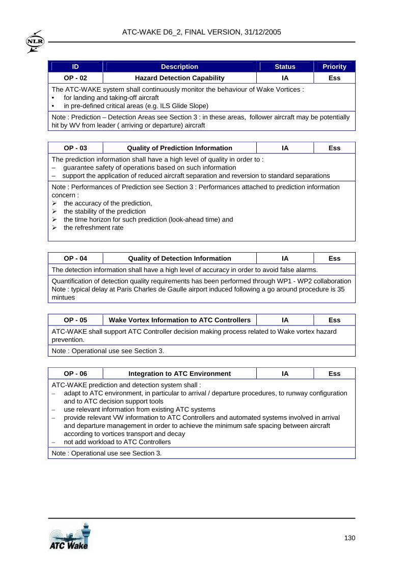
ATC-WAKE D6_2, FINAL VERSION, 31/12/2005
130
ID Description Status Priority
OP - 02 Hazard Detection Capability IA Ess
The ATC-WAKE system shall continuously monitor the behaviour of Wake Vortices : • for landing and taking-off aircraft • in pre-defined critical areas (e.g. ILS Glide Slope)
Note : Prediction – Detection Areas see Section 3 : in these areas, follower aircraft may be potentially hit by WV from leader ( arriving or departure) aircraft
OP - 03 Quality of Prediction Information IA Ess
The prediction information shall have a high level of quality in order to : – guarantee safety of operations based on such information – support the application of reduced aircraft separation and reversion to standard separations
Note : Performances of Prediction see Section 3 : Performances attached to prediction information concern : � the accuracy of the prediction, � the stability of the prediction � the time horizon for such prediction (look-ahead time) and � the refreshment rate
OP - 04 Quality of Detection Information IA Ess
The detection information shall have a high level of accuracy in order to avoid false alarms.
Quantification of detection quality requirements has been performed through WP1 - WP2 collaboration Note : typical delay at Paris Charles de Gaulle airport induced following a go around procedure is 35 mintues
OP - 05 Wake Vortex Information to ATC Controllers IA Ess
ATC-WAKE shall support ATC Controller decision making process related to Wake vortex hazard prevention.
Note : Operational use see Section 3.
OP - 06 Integration to ATC Environment IA Ess
ATC-WAKE prediction and detection system shall : – adapt to ATC environment, in particular to arrival / departure procedures, to runway configuration
and to ATC decision support tools – use relevant information from existing ATC systems – provide relevant VW information to ATC Controllers and automated systems involved in arrival
and departure management in order to achieve the minimum safe spacing between aircraft according to vortices transport and decay
– not add workload to ATC Controllers
Note : Operational use see Section 3.
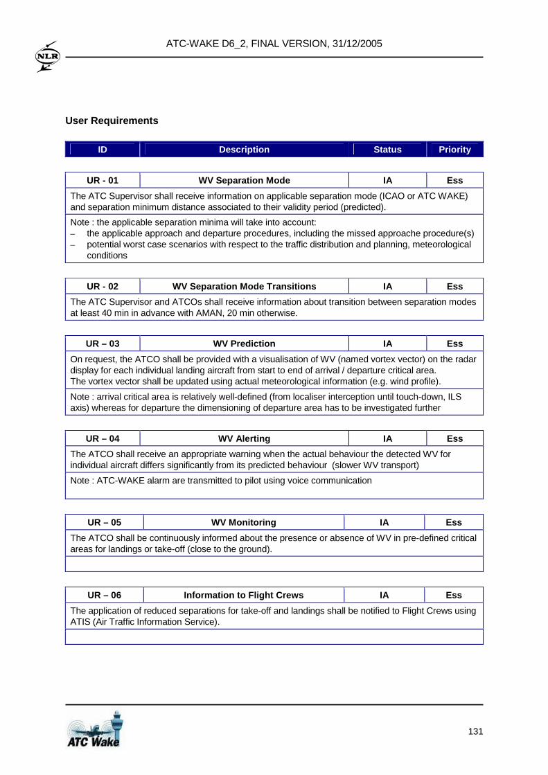
ATC-WAKE D6_2, FINAL VERSION, 31/12/2005
131
User Requirements
ID Description Status Priority
UR - 01 WV Separation Mode IA Ess
The ATC Supervisor shall receive information on applicable separation mode (ICAO or ATC WAKE) and separation minimum distance associated to their validity period (predicted).
Note : the applicable separation minima will take into account: – the applicable approach and departure procedures, including the missed approache procedure(s) – potential worst case scenarios with respect to the traffic distribution and planning, meteorological
conditions
UR - 02 WV Separation Mode Transitions IA Ess
The ATC Supervisor and ATCOs shall receive information about transition between separation modes at least 40 min in advance with AMAN, 20 min otherwise.
UR – 03 WV Prediction IA Ess
On request, the ATCO shall be provided with a visualisation of WV (named vortex vector) on the radar display for each individual landing aircraft from start to end of arrival / departure critical area. The vortex vector shall be updated using actual meteorological information (e.g. wind profile).
Note : arrival critical area is relatively well-defined (from localiser interception until touch-down, ILS axis) whereas for departure the dimensioning of departure area has to be investigated further
UR – 04 WV Alerting IA Ess
The ATCO shall receive an appropriate warning when the actual behaviour the detected WV for individual aircraft differs significantly from its predicted behaviour (slower WV transport)
Note : ATC-WAKE alarm are transmitted to pilot using voice communication
UR – 05 WV Monitoring IA Ess
The ATCO shall be continuously informed about the presence or absence of WV in pre-defined critical areas for landings or take-off (close to the ground).
UR – 06 Information to Flight Crews IA Ess
The application of reduced separations for take-off and landings shall be notified to Flight Crews using ATIS (Air Traffic Information Service).
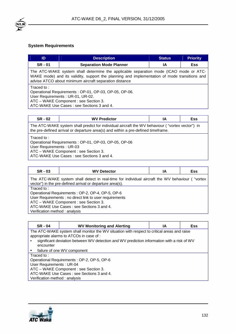
ATC-WAKE D6_2, FINAL VERSION, 31/12/2005
132
System Requirements
ID Description Status Priority
SR - 01 Separation Mode Planner IA Ess
The ATC-WAKE system shall determine the applicable separation mode (ICAO mode or ATC-WAKE mode) and its validity, support the planning and implementation of mode transitions and advise ATCO about minimum aircraft separation distance
Traced to : Operational Requirements : OP-01, OP-03, OP-05, OP-06. User Requirements : UR-01, UR-02. ATC – WAKE Component : see Section 3. ATC-WAKE Use Cases : see Sections 3 and 4.
SR - 02 WV Predictor IA Ess
The ATC-WAKE system shall predict for individual aircraft the WV behaviour ( “vortex vector”) in the pre-defined arrival or departure area(s) and within a pre-defined timeframe.
Traced to : Operational Requirements : OP-01, OP-03, OP-05, OP-06 User Requirements : UR-03 ATC – WAKE Component : see Section 3. ATC-WAKE Use Cases : see Sections 3 and 4.
SR - 03 WV Detector IA Ess
The ATC-WAKE system shall detect in real-time for individual aircraft the WV behaviour ( “vortex vector”) in the pre-defined arrival or departure area(s). Traced to : Operational Requirements : OP-2, OP-4, OP-5, OP-6 User Requirements : no direct link to user requirements ATC – WAKE Component : see Section 3. ATC-WAKE Use Cases : see Sections 3 and 4. Verification method : analysis
SR - 04 WV Monitoring and Alerting IA Ess The ATC-WAKE system shall monitor the WV situation with respect to critical areas and raise appropriate alarms to ATCOs in case of : • significant deviation between WV detection and WV prediction information with a risk of WV
encounter • failure of one WV component Traced to : Operational Requirements : OP-2, OP-5, OP-6 User Requirements : UR-04 ATC – WAKE Component : see Section 3. ATC-WAKE Use Cases : see Sections 3 and 4. Verification method : analysis