Embed Size (px)
Citation preview
Electronics and Communications in Japan, Part 1, Vol. 77, No. 8, 1994 Tmnsirted from D e a l Joho Twahin Gakkai Ronbunrhi. Vol. 76-%I, No. 11. November 1993, pp. 869-881
ATM-Oriented Multimedia LAN Architecture
Hiroshi Suzuki, Atsushi Iwata, Chinatsu Ikeda and Naoki Mori, Members
C & C Systems Research Laboratories, NEC Corporation, Kawasaki, Japan 216
SUMMARY
The shared media local area networks (LAN) such as EthernetEDDI has the bottleneck of bandwidth scal- ability. ATMLAN based on asynchronous transfer mode (ATM) switch is considered interesting at present as the next-generation multimedia LAN to dissolve th is bottle- neck. The re.search and development of ATM has mostly been promoted for application to the public network. With respect to LAN, a new investigation is needed which includes the architecture since there are various requirements such as compatibility to the existing proto- col, the simplification of the network control, and the drastic reduction of the system cost.
This paper proposes the ATM-oriented multimedia LAN (ATOMLAN) architecture which meets the fore- mentioned requirements. The proposed architecture has the following three features: (1) the ATMLAN address- ing, considering the affinity to the existing protocol and the efficient internetworking; (2) the high-speed COMS-
tion control to realize a high throughput for the con- nectionless-type data transfer; and (3) the simple and efficient traffic control for the high-speed burst-multi- media service. Using the proposed architecture, a seam- less high-speed multimedia network can be realized, from the desk-top to the broadband network.
Keywords: ATM; LAN; address; signaling; traf- fic control.
1. Introduction
1.1. ATMLAN and its necessity
With the recent rapid development of the desk-top computers into the high-speed/multimedia configuration, there has been an increasing demand for the high-speed multimedia local area networks (LAN), which has the broadband to provide the throughput of several tens to several hundreds Mbit/s per terminal, and which can support the quality control for the multimedia. For this requirement, an effort is made to realize a high-speed LAN by extending the shared multimedia-type LAN, such as the conventional Ethernet/FDDI, as in the case of FFOL [7]. There are the following limits of perfor- mance in the realization of the high-speed multimedia LAN by extending the shared multimedia-type LAN.
(1) Bandwidth bottleneck. When terminals on LAN execute simultaneously the high-speed applications of several tens Mbit/s, LAN to contain those must have the network capacity of Gbit/s. If such a system is real- ized by the shared media-type LAN, WS interfaces con- nected to LAN must also have the interface rate of Gbit/s, which increases the cost.
(2) Lack of consistency in access control. In ex- panding the network capacity /size by the shared media- type LAN, the optimal media access method must be modified from token-ring to multiple-token-ring, for
69 ISSN 1042-0967/94/0008-0069 Q 1995 Scripta Technics, Inc.
example, from the viewpoint of the distance dependency and the uniformity of service.
(2) In the connection-oriented ATM, how can the conventional connectionless service be supported?
(3) Complexity of multimedia traffic control. When the quality control of priority control is used for the CBR traffic, the control becomes complex, as in the case where the movable boundary technique is applied,
In contrast to such an approach, the star-type mesh high-speed LAN using the switch, as in the case of Auto- net [14], also is considered interesting as a means to dissolve the aforementioned bottleneck. Among those, ATMLAN using the asynchronous transfer mode devel- oped for the public network (B-ISDN/ATM) technique is considered promising from the viewpoint of the support of the high-speed multimedia and the connection to the broadband network. Intensive effort toward standardiza- tion is being made from the industrial sector, as is seen in the case of ATM Forum [8].
ATMLAN in this sense has the topology of stadmesh type. The terminal is of the star type and is contained in the switch (local switch). The local switches are connected by mesh or by the backbone switch. In such a star-type topology, the speed of each rate can be reduced to the value as is required between the terminal and the switch, as long as the switch has the capacity of Gbith. This helps to reduce the cost of the terminal interface. The ATM switch with the capacity of 100 Mbitls to Gbitls has already been developed [15]. Conse- quently, a high-speed, largecapacity network can be realized by the uniform access method. By increasing the number of switches, the network capacity can be expand- ed accordingly.
1.2. Technical problems in ATMLAN
It should be noted, however, that research and development of ATM have mostly been promoted taking into account the public network. When the ATM tech- nique is to be applied to LAN, there are great differences in the requirements, especially in terms of the protocol, network control, and system cost. Thus, new investiga- tions which include the architecture are needed between the public and private networks from the viewpoint of the compatibility to the existing LAN.
It seems especially important to solve the following three technical problems.
(1) In starlmesh-type LAN, how can a simple routinglintemetworking be realized?
(3) In the public network, how can the complicat- ed traffic control be simplified? Especially, how can the congestion control for the high-speed bursty data traffic be realized?
More precisely, problem (1) is how to realize the simple data transfer function based on broadcast realized by the shared media and the intemetworking function realized by the router, using the ATMLAN with the star- type topology. In other words, the keys are the high- speed local routing function as the bridging elements and the intemetworking technique among the wider area ATMLAN as the routing element.
With respect to problem (2), the mesh connection of the permanent connections (PVClVP) and the method using the connectionless server have been proposed [5, 111. The method by PVC can be used for the connection between routers. It is not suited to the case due to the number of VC where each desk-top computer requires a connection for each application. The method using the connectionless server can be used when the system han- dles mostly interactive data and the throughput is low, as in the present situation. However, when the high-speed data service is increased, a bottleneck is produced in the throughput in improving the end-to-end performance, unless the switch-based, high-speed router [19] or other elaborations are included. For those problems, Cidon and Gopal [3] and Roberts et al. [13] propose methods for high-speed connection settings. A problem then is that the simplification of the protocol is limited, since both the bandwidth reservation and the speed improvement of the connection route setting are considered. In other words, a simpler procedure is desired.
With respect to problem (3) of ATM traffic con- trol, a very strict service quality as well as a complex call acceptance/policing control in the public network are required since there is an accounting process. Thus, it is considered desirable to simplify the traffic control to be supported in LAN and to reduce the cost by providing the terminal protocol with the flow control function, as in the case of TCP/IP protocol. Only the high-speed bursty traffic will flow into the network in LAN directly from the computer without the policing control. Then a framework is required which can efficiently prevent the congestion by a simple control.
70
PVC/SVC
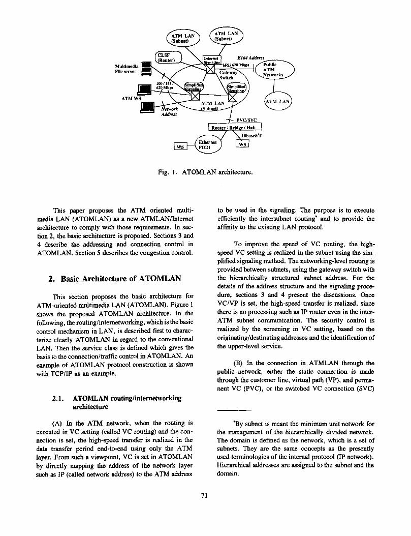
Fig. 1. ATOMLAN architecture.
Th~s paper proposes the ATM oriented multi- media LAN (ATOMLAN) as a new ATMLANIInternet architecture to comply with those requirements. In sec- tion 2, the basic architecture is proposed. Sections 3 and 4 describe the addressing and connection control in ATOMLAN. Section 5 describes the congestion control.
2. Basic Architecture of ATOMLAN
This section proposes the basic architecture for ATM-oriented multimedia LAN (ATOMLAN). Figure 1 shows the proposed ATOMLAN architecture. In the following, the routing/internetworking , which is the basic control mechanism in LAN, is described first to charac- terize clearly ATOMLAN in regard to the conventional LAN. Then the service class is defined which gives the basis to the connection/traffic control in ATOMLAN. An example of ATOMLAN protocol construction is shown with TCP/IP as an example.
2.1. ATOMLAN routing/intemetworking architecture
(A) In the ATM network, when the routing is executed in VC setting (called VC routing) and the con- nection is set, the high-speed transfer is realized in the data transfer period end-to-end using only the ATM layer. From such a viewpoint, VC is set in ATOMLAN by directly mapping the address of the network layer such as IP (called network address) to the ATM address
to be used in the signaling. The purpose is to execute efficiently the intersubnet routing' and to provide the affinity to the existing LAN protocol.
To improve the speed of VC routing, the high- speed VC setting is realized in the subnet using the sim- plified signaling method. The networking-level routing is provided between subnets, using the gateway switch with the hierarchically structured subnet address. For the details of the address structure and the signaling proce- dure, sections 3 and 4 present the discussions. Once VClVP is set, the high-speed transfer is realized, since there is no processing such as IP router even in the inter- ATM subnet communication. The security control is realized by the screening in VC setting, based on the originating/destinating addresses and the identification of the upper-level service.
(B) In the connection in ATMLAN through the public network, either the static connection is made through the customer line, virtual path (VP), and perma- nent VC (PVC), or the switched VC connection (SVC)
-By subnet is meant the minimum unit network for the management of the hierarchically divided network. The domain is defined as the network, which is a set of subnets. They are the same concepts as the presently used terminologies of the internal protocol (IP network). Hierarchical addresses are assigned to the subnet and the domain.
71
Low IosqLow delay
CL : PVC mode CO :SVC mode CO : SVC mode
Fig. 2. ATOMLAN service class and connection control.
is made by the address conversion to the public network using the gateway switch,
(C) The connection to the conventional-type LAN such as EthernetlFDDI is made through the router or bridge. ATM addresses are allocated to the routerhridge in the same way as to the terminal, and the SVClPVC connection between routershridges is realized.
Generally, it is considered that ATMLAN has a more significant role as the backbone for the convention- al Ethernet/FDDI, etc., in the introduction phase. As dis- cussed in the foregoing, in the ATOMLAN proposed in this paper however, the signaling processing itself con- tains the routinglinternetworking function by the network layer protocol, which is used at present by Internet and is employed directly in the desk-top computer. By this elaboration, ATOMLAN can act as a front-end LAN to contain directly the desk-top computer for which a fur- ther speed improvement is expected and as the conven- tional router. Then a significant feature is produced that the seamless internetworking archtecture is provided which extends from the desk-top computer to the wide- area Internet.
2.2. Service class and connection control
The service class is defined in the following, which gives the basis for the connection control and the traffic control in ATOMLAN. The following three service classes are supported to cope with the increasing stream- type services, such as the high-speed file transfer and audio/video, in addition to the conventional interactive
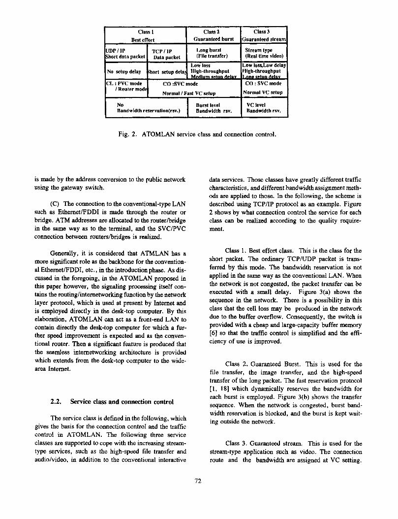
data services. Those classes have greatly different traffic characteristics, and different bandwidth assignment meth- ods are applied to those. In the following, the scheme is described using TCP/IP protocol as an example. Figure 2 shows by what connection control the service for each class can be realized according to the quality require- men t .
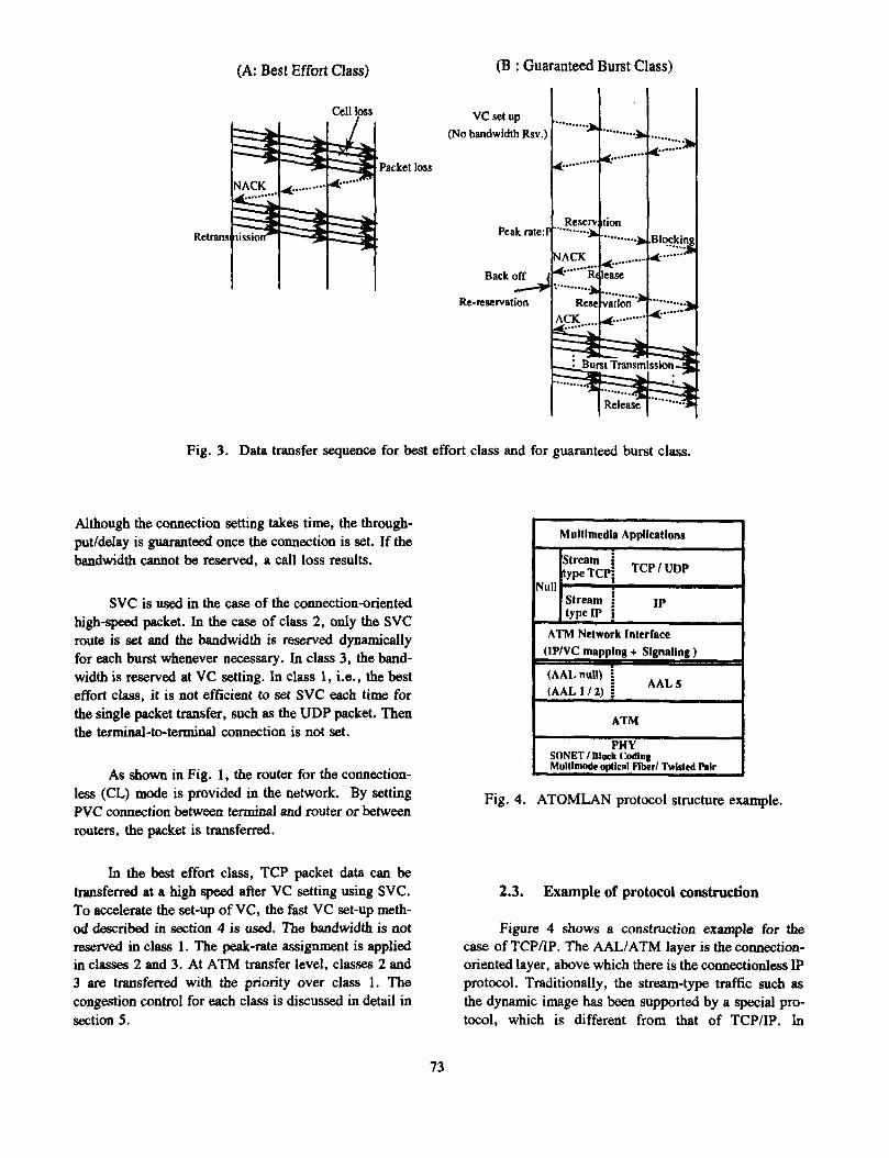
Class 1. Best effort class. This is the class for the short packet. The ordinary TCPlUDP packet is trans- f e n d by this mode. The bandwidth reservation is not applied in the same way as the conventional LAN. When the network is not congested, the packet transfer can be executed with a small delay. Figure 3(a) shows the sequence in the network. There is a possibility in this class that the cell loss may be produced in the network due to the buffer overflow. Consequently, the switch is provided with a cheap and large-capacity buffer memory [a] so that the traffic control is simplified and the effi- ciency of use is improved.
Class 2. Guaranteed Burst. This is used for the file transfer, the image transfer, and the high-speed transfer of the long packet. The fast reservation protocol [l, 181 which dynamically reserves the bandwidth for each burst is employed. Figure 3(b) shows the transfer sequence. When the network is congested, burst band- width reservation is blocked, and the burst is kept wait- ing outside the network.
Class 3. Guaranteed stream. This is used for the stream-type application such as video. The connection route and the bandwidth are assigned at VC setting.
72
(A: Best Effort Class)
Cell loss
(B : Guaranteed Burst Class)
(NO bandwidth Rsv.)
Re-mservation
Fig. 3. Data transfer sequence for best effort class and for guaranteed burst class.
Although the connection setting takes time, the through- put/delay is guaranteed once the connection is set. If the bandwidth cannot be reserved, a call loss results.
SVC is used in the case of the connection-oriented high-speed packet. In the case of class 2, only the SVC route is set and the bandwidth is reserved dynamically for each burst whenever necessary. In class 3, the band- width is reserved at VC setting. In class 1, i.e., the best effort class, it is not efficient to set SVC each time for the single packet transfer, such as the UDP packet. Then the terminal-to-terminal connection is not set.
As shown in Fig. 1, the router for the connection- less (CL) mode is provided in the network. By setting PVC connection between terminal and router or between routers, the packet is transferred.
In the best effort class, TCP packet data can be transferred at a high speed after VC setting using SVC. To accelerate the set-up of VC, the fast VC set-up meth- od described in section 4 is used. The bandwidth is not reserved in class 1. The peak-rate assignment is applied in classes 2 and 3. At ATM transfer level, classes 2 and 3 are transferred with the priority over class 1. The congestion control for each class is discussed in detail in section 5.
Multimedia Applications 1 I [ream 1 Ip I Null
type TCpf TCP ’ UDP
Stream type IP
I ATM Network Interface 1
(AALnull) (AAL1/2) i - AALS
ATM
SONEI I Dlock Coding Mulllmode oplicat Fiber/ Twisted Rir
Fig. 4. ATOMLAN protocol structure example.
2.3. Example of protocol construction
Figure 4 shows a construction example for the case of TCP/IP. The AALIATM layer is the connection- oriented layer, above which there is the connectionless 1P protocol. Traditionally, the stream-type traffic such as the dynamic image has been supported by a special pro- tocol, which is different from that of TCPIIP. In
73

Signaling Handler as Router sentially important role in the foregoing signaling/VC routing. This section proposes an addressing method in ATOMLAN. The ATM address is the address used in the signaling in the connection setting to identify the private ATM network access point.
VC Setup phase: Internetwok capable signaling
3.1. Standardization and problems
Data transfer phase : Hardware switching
Fig. 5. Internetwork capable signaling and high- speed data transfer with hardware switching.
ATOMLAN, TCP/IP is extended to include the stream- type TCP/IP [20], where the bandwidth reservation function and the quality assurance function is supported so that the foregoing traffic can be handled in a unified way with the data packet.
The ATM interface layer has the mapping table for the object IP address and VC. If VC is set to the object host, the packet is transferred by that VC. If there is no VC to the object IP address host, the signaling for SVC setting is started. At the same time, the bandwidth is reserved according to the required quality. As AAL, AAL5 [8] is used in a unified way, which can simplify the processings for both data and signaling, to reduce the cost of the interface. It may be sensible to use AALnull, etc., for the stream-type, where the user can give specifi- cations in the flexible way. The speed of the physical layer is 100 to 620 Mbitls. It is effective to apply the framing by SONET/Block coding and to reduce the cost by the multimode fiber or twisted line transmission.
3. ATOMLAN Addressing Oriented To-
Seamless Network ward
As pointed out in section 2.1, ATOMLAN has the seamless internetworking function from the desk-top computer to the wide-area broadband Internet. When an inter-LAN connection is to be made as in Fig. 5 , the signaling handler of the gateway switch acts as the conventional router in the signaling phase. Once VC is set end-to-end, the high-speed data transfer is executed by the hardware switch. ATM addressing plays the es-
In ATM Forum, it is agreed to use NSAP address [4] of OSI as the ATM UNI address in the private net- work. A method is adopted whereby the media access control (MAC) layer address (called MAC address) of the data link sublayer, which has been used in the con- ventional LAN, and the newly defined hierarchically network number are combined to be used as the system identifier field value of NASP address. An optional method also is specified [12, 161 where the network address is mapped directly to NASP.
When MAC address is used as ATM UNI address, the address resolution (AR) must be executed which determines the ATM UNI address from the destination network address. To realize the end-to-end VC setting through ATM subnet, however, AR must be executed over subnets as is shown in Fig. 6(A) and the existing concurrent-type AR protocol cannot directly be utilized. Then it is necessary to place AR servers in a hierarchical way and to transfer the AR protocol packet. The network must have the routing function by network addressing for the AR protocol packet transfer in addition to the VC routing function by MAC address. Then the procedure for VC setting also becomes complicated. Even if the problem concerning AR is solved, there must be some hierarchical address information to set VC at a high speed between switches in ATM subnet, since MAC address does not have a hierarchical structure.
3.2. ATM UNI address using network address
Based on the aforementioned reasoning, the net- work address with subnet/domain address structure is used directly as ATM UNI address in ATOMLAN as the ATM UNI address method suited to the internetworking without requiring a complex AR procedure on the termi- nal side. If the existing network address, such as IP, IPX, and Apple Talk, is used directly as ATM UNI address, the internetworking by ATM can be realized by the minimum modification of the terminal-side protocol. Consequently, the address composed as
[address type] + [network address]
74
SwitchlARP swver
:ceding
B psckel
(B)
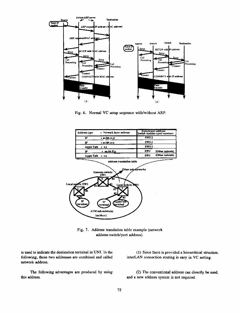
Fig. 6. Normal VC setup sequence with/without ARP.
IP + aa.bb.m.d ! sw2-2
t IP + aa.bb.cc.e I SW3-2 AppleTalk t x.y SWJ-1 I IP t aa.bb.fl.g I SWI (Other subnets) AppleTaIk t 7-L SWI (Olher subnets)
a d d r w translation table
ATM sub-networks
Fig. 7. Address translation table example (network address-switch/port address).
is used to indicate the destination terminal in UNI. In the following, those two addresses are combined and called network address.
The following advantages are produced by using this address.
(1) Since there is provided a hierarchical structure, interLAN connection routing is easy in VC setting.
(2) The conventional address can directly be used, and a new address system is not required.
75
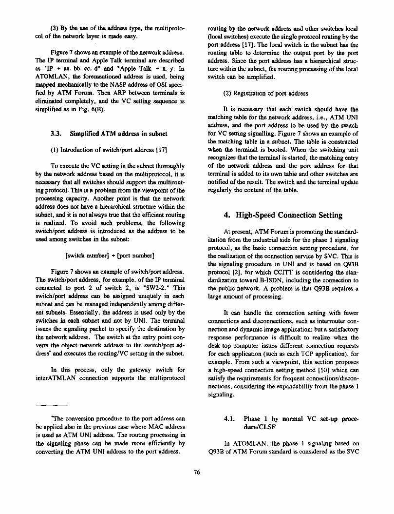
(3) By the use of the address type, the multiproto- col of the network layer is made easy.
Figure 7 shows an example of the network address. The IP terminal and Apple Talk terminal are described as "IP + aa. bb. cc. d" and "Apple Talk + x. y. In ATOMLAN, the forementioned address is used, being mapped mechanically to the NASP address of OSI speci- fied by ATM Forum. Then ARP between terminals is eliminated completely, and the VC setting sequence is simplified as in Fig. 6(B).
3.3. Simplified ATM address in subnet
(1) Introduction of switchlport address [ 171
To execute the VC setting in the subnet thoroughly by the network address based on the multiprotocol, it is necessary that all switches should support the multirout- ing protocol. This is a problem from the viewpoint of the processing capacity. Another point is that the network address does not have a hierarchical structure within the subnet, and it is not always true that the efficient routing is realized. To avoid such problems, the following switch/port address is introduced as the address to be used among switches in the subnet:
[switch number] + [port number]
Figure 7 shows an example of switchlport address. The switchlport address, for example, of the IP terminal C O M ~ C ~ ~ to port 2 of switch 2, is "SW2-2." This switch/port address can be assigned uniquely in each subnet and can be managed independently among differ- ent subnets. Essentially, the address is used only by the switches in each subnet and not by UNI. The terminal issues the signaling packet to specify the destination by the network address. The switch at the entry point con- verts the object network address to the switch/port ad- dress' and executes the routing/VC setting in the subnet.
In this process, only the gateway switch for interATMLAN connection supports the multiprotocol
routing by the network address and other switches local (local switches) execute the single protocol routing by the port address [17]. The local switch in the subnet has the routing table to determine the output port by the port address. Since the port address has a hierarchical struc- ture withii the subnet, the routing processing of the local switch can be simplified.
(2) Registration of port address
It is necessary that each switch should have the matching table for the network address, i.e., ATM UNI address, and the port address to be used by the switch for VC setting signalling. Figure 7 shows an example of the matching table in a subnet. The table is constructed when the terminal is booted. When the switching unit recognizes that the terminal is started, the matching entry of the network address and the port address for that terminal is added to its own table and other switches are notified of the result. The switch and the terminal update regularly the content of the table.
4. High-speed Connection Setting
At present, ATM Forum is promoting the standard- ization from the industrial side for the phase 1 signaling protocol, as the basic connection setting procedure, for the realization of the connection service by SVC. This is the signaling procedure in UNI and is based on Q93B protocol [2], for which CCITT is considering the stan- dardization toward B-ISDN, including the connection to the public network. A problem is that Q93B requires a large amount of processing.
It can handle the connection setting with fewer connections and disconnections, such as interrouter con- nection and dynamic image application; but a satisfactory response performance is difficult to realize when the desk-top computer issues different connection requests for each application (such as each TCP application), for example. From such a viewpoint, this section proposes a high-speed connection setting method [lo] which c a ~ ~ satisfy the requirements for frequent connections/discon- nections, considering the expandability from the phase 1 signaling.
The conversion procedure to the port address can be applied also in the previous case where MAC address is used as ATM UNI address. The routing processing in the signaling phase can be made more efficiently by converting the ATM UNI address to the port address.
4.1. Phase 1 by normal VC set-up pme- dure/CLSF
In ATOMLAN, the phase 1 signaling based on Q93B of ATM Forum standard is considered as the SVC
76
set-up procedure with fewer connections/disconnetions. It is called normal VC set-up procedure. The normal VC &-up procedure c811 directly be applied to the VC &-up of class 3, but a satisfactory performance is not obtained for class 1/2 since there is a severe requirement for the response time.
Use of connection server.
For class 112, one or more connectionless servers (CLSFhouter) is provided for each subnet as is shown in Fig. 1. VC is set beforehand in a star from the terminals to CLSF, and CLSF executes the point-to-point trans- ferlpoint-to-multipoint transfer by IP routing. The data transfer between ATM subnets is executed by realizing the internetworking by the permanent multistage WMW-
tion among CLSF. However, it should be noted that the present routing bottleneck is maintained directly by this approach. When the high-speed data communication service is increased further in the future, the load will concentrate to CLSF, which sets the limit of perfor- mance.
4.2. Phase 2 introducing fast VC set-up meth- Od
To avoid the aforementioned bottleneck of the connectionless server, the SVC set-up procedure itself is improved in speed also for the service of class 1/2. The method is called the fast VC set-up method. As a method to set-up VC at a high speed, there is already a method to set-up VC on the expected path beforehand and to reduce the number of signaling stages in the intermediate switches between the transmitting and the receiving terminals. The connection set-up time at the input and output switches, however, cannot be reduced only by setting up VC. Another method, which seems useful, is not to release the once-set connection, but to retain the connection for a certain time-out period, in the same way as the caching method for the object MAC address in ARP. This method also has a problem in that a larger number of VC is needed when the time-out is set longer, thereby increasing the waste of resources.
In the following, the reduction of the VC setting time itself is considered. The essential idea in the pro- posed high-speed VC set-up method is to execute the connection set-up by the hardware by separating the bandwidth. The best effort class is the class without the bandwidth reservation. Consequently, it suffices that the connection route set-up is accelerated. The idea of the source routing, which is one of the packet route selection
methods, is introduced into VC routing, and the hard- ware-oriented connection set-up is r e a l i d .
For the class 2, i.e., the guaranteed burst class, the connection set-up is executed without the bandwidth reservation in the call set-up phase, as shown in Fig. 3. Then the fast reservation protocol [ 1, 181 is used, where the reservation is allocated only to the peak bandwidth immediately before and after the burst transfer. Since the bandwidth is reserved only for the already set COM~C-
tion, the speed of the hardware can be improved. The fast VC set-up proposed in this section differs from the fast reservation protocol in the following point. The latter aims at the acceleration of the bandwidth reservation on the already set connection, while the former aims at only the acceleration of the connection set-up, without execut- ing the bandwidth reservation. In both methods, the bandwidth and the connection are controlled separately, but the purposes of application are essentially different.
The proposed fast VC set-up method is realized by combining the source route cache and the self-VC set-up. The fast VC set-up method executes only the connection route set-up, and does not ensure the bandwidth of the set-up VC. Consequently, the method is applied essen- tially to the class 1, i.e., the best effort class, where VC is set up for each TCP connection. The method can also be applied to class 2 in the connection route set-up phase, since the bandwidth reservation is not executed. The operation in this method is described in the follow- ing.
Source-route cache.
In the conventional Q93B protocol, each switch analyzes the object address and determines the output port by referring to the route table. To reduce the delay in the route set-up, the intermediate route is specified by the source side in the proposed method. The information concerning the intermediate route is acquired by the source by the extended normal VC set-up method, which is the standard connection set-up procedure, without using any special route search procedure. When VC is set up by the normal VC set-up method based on the destination IP address, the intermediate route information between the transmitter and the receiver is sent to the terminal or the switch to which the terminal is connected (called terminal-connected switch) and the information is cachdd, by the terminal or the terminal connected switch.
When the terminal sets up a new VC, if there exists a route information needed by that VC in the foregoing cachd, that route information is sent together
77
SETUP message with Source route info. Source Snitch Switch Destination - 1 I I I
Source route ache table
(A) Source routing VC Setup
Free VCI
Self VC Setup
L
Fig. 8. Fast VC setup scheme.
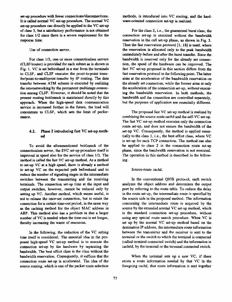
with the SETUP message, as shown in Fig. 8(A). Even if there does not exist a route information needed by VC in the cache of the terminal, if such exists in the cache of the terminal-connected switch, the information is convert- ed into the SETUP message with the route information by the tenninalannected switch for the SETUP message sent by the terminal by the normal VC Setup, and the result is sent to the next switch. In either case, each switch can set up VC with a high-speed routing without referring to the routing table. After setting up VC, the ordinary data transfer is executed.
There can be two methods to represent the routing information. One is to represent the route by the list of intermediate switch numbers, and the other is to repre- sent the route by the list of the port numbers in the switch. Figure 8(A) is an example where the terminal specifies the intermediate port numbers. In the example of this figure, the source route information of "Port1 - Port2 - Pod," which is the concatenation of the port numbers of the intermediate switches, is put on the SET- UP message to set the connection to the destination terminal IP3. In this case, the connection set-up time can be reduced without executing the normal VC set-up by increasing the cach6 holding time of the source route. It is necessary to set adaptively the time-out for the route cache according to the update interval of the route table so that the system can follow the change of the network configuration or the change of the route information.
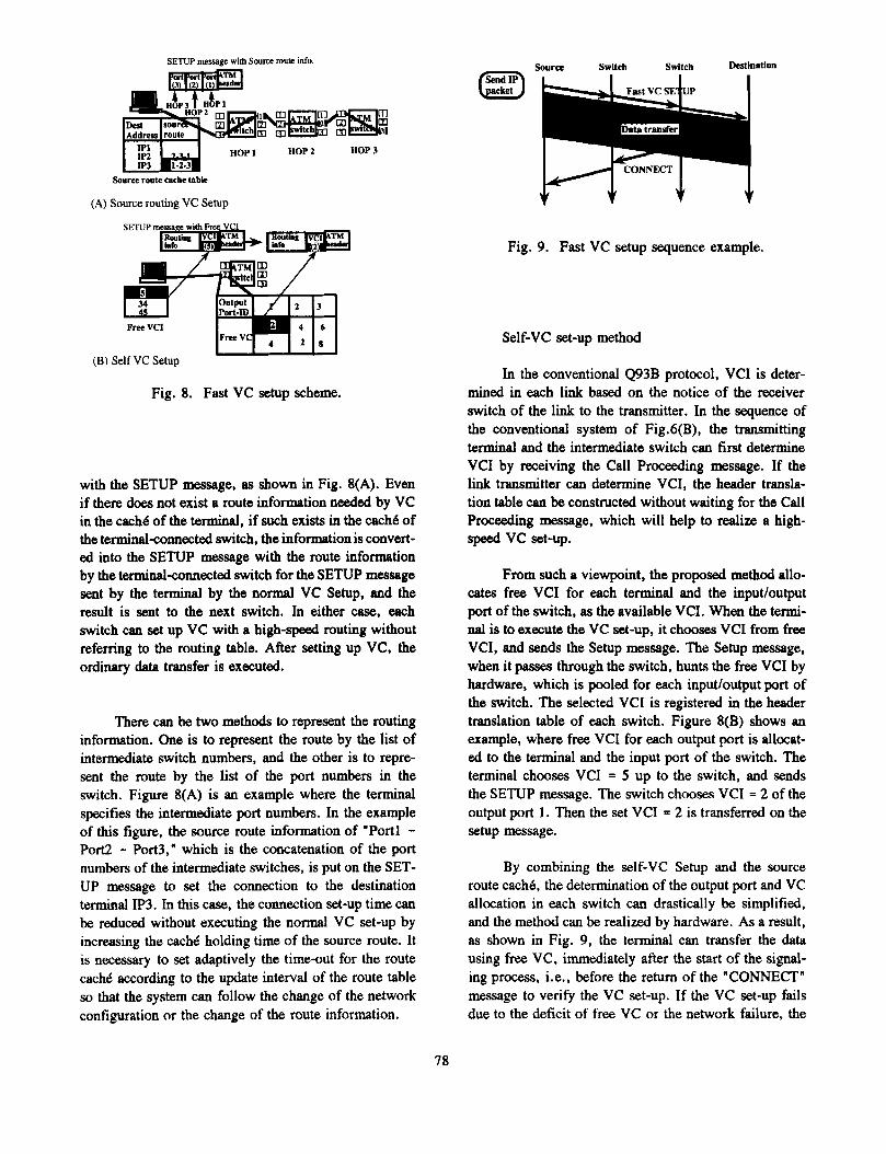
Fig. 9. Fast VC setup sequence example.
Self-VC set-up methd
In the conventional Q93B protocol, VCI is deter- mined in each link based on the notice of the receiver switch of the link to the transmitter. In the sequence of the conventional system of Fig.6(B), the transmitting terminal and the intermediate switch can first determine VCI by receiving the Call Proceeding message. If the link transmitter can determine VCI, the header transla- tion table can be constructed without waiting for the Call Proceeding message, which will help to realize a high- speed vc set-up.
From such a viewpoint, the proposed method allo- cates free VCI for each terminal and the inputloutput port of the switch, as the available VCI. When the termi- nal is to execute the VC set-up, it chooses VCI from free VCI, and sends the Setup message. The Setup message, when it passes through the switch, hunts the free VCI by hardware, which is pooled for each input/output port of the switch. The selected VCI is registered in the header translation table of each switch. Figure 8(B) shows an example, where free VCI for each output port is allocat- ed to the terminal and the input port of the switch. The terminal chooses VCI = 5 up to the switch, and sends the SETUP message. The switch chooses VCI = 2 of the output port 1. Then the set VCI = 2 is transferred on the setup message.
By combining the self-VC Setup and the source route cach6, the determination of the output port and VC allocation in each switch can drastically be simplified, and the method can be realized by hardware. As a result, as shown in Fig. 9, the terminal can transfer the data using free VC, immediately after the start of the signal- ing process, i.e., before the return of the "CONNECT" message to verify the VC set-up. If the VC set-up fails due to the deficit of free VC or the network failure, the
78
procedure is switched to the normal VC Setup and the VC set-up is executed.
preventive control, which predicts the quality and pre- vents the congestion.
The n o d VC Setup based on Q93B of Fig. 6(B) and the data transfer sequence based on the fast VC set- up method of Fig. 9 are compared as follows. In the normal VC Setup, the VC set-up procedure is of a low speed and the data transfer is blocked until the CON- NECT message is received. However, in the fast VC set- up method, the processing in the switch node is simpli- fied and is processed by the hardware. Then the data transfer can be started immediately after the transfer of SETUP message. As a result, the transmission efficiency can be improved when the data transfer time is de- creased. Another point is that the connection set-up is not affected by the round-trip propagation delay, even if it is of a wide area. This helps to realize the highly efficient transfer. Thus, in the fast VC set-up method, the same response time as in the use of the connectionless server is realized. Since the connection is actually specified, the succseding packets are transferred with a high speed, thereby eliminating the bottleneck for the performance as is observed in CLSF.
5. ATOMLAN Congestion Control Method
5.1. Basic principle of congestion control
As discussed in section 2, among the service class- es supported by ATOMLAN, the guaranteed stream class (class 3) executes the peak rate allocation at the call level. The best effort class (class 1) and the guaranteed burst class (class 2) are the classes for which the statisti- cal multiplexing is applied at the cell level and the burst level, respectively. Since a congestion arises in the high- ly loaded situation, how to prevent the congestion is one of the most important issues. Since there is no accounting process in LAN, the quality requirement/assurance is not decided strictly between the network operator and the network user. It is possible to provide the flow control function to the terminal side protocol. The costdown on the side of the network is required as far as possible. From such a viewpoint, it is desired to simplify the traffic control on the network side as far as possible.
From such a viewpoint, ATOMLAN adopted the shaping method only for the self-peak rate, which can easily be realized by the hardware of the network inter- face. Accordingly, the congestion control for the service classes 1 and 2 also is based on the peak-rate control. To simplify the control as far as possible, the following reactive control is proposed, rather than the complex
5.2. Reactive congestion control method
5.2.1. Congestion control method for class 1
The use of the reactive control is considered, where a congestion is detected, and the transmission ratelpeak rate is reduced, so that the cell loss rate can be reduced. The following two methods are considered.
[a] Reactive control for each VC
The congestion is detected using NACK signal, time-out and ECN [22] end-to-end. The rate is adjusted stepwise according to the extent of congestion, and is determined by the past number of transmission suc- cess /failures.
[b] Reactive control for each link
The node monitors the buffer size. If the content reaches a certain threshold, the backpressure signal is returned to the previous stage to avoid the buffer over- flow. Then the transmission rate of the previous node is reduced. The rate is defined as multirates.
The reactive control for each VC is executed end- to-end, after a congestion occurs. Then the cell loss becomes inevitable in the highly loaded situation which leads to the deterioration of the throughput. It seems necessary to apply the reactive control (back-pressure control) to each link in class 1 [21]. The backpressure control is applied only to class 1, so that the traffic in classes 2 and 3 with higher priorities is not affected.
5.2.2. Congestion control for class 2
In class 2, when the bandwidth is reserved for each burst, the congestion detection or adaptive bandwidth allocation according to the left bandwidth in the network can be applied using the control cells to be used in the reservation. The reactive congestion control is realized by those functions. The congestions is detected and the peak rate is determined for each case as follows.
(a) Failure in bandwidth reservation. As in the reactive control for VC in class 1, the congestion is detected based on the failure in the bandwidth allocation. The peak rate is adjusted by multirate, and is determined
79
by the numbers of successes and failures of the band- width reservation.
(b) The peak rate is adjusted adaptively according to the left bandwidth. The bandwidth to be allocated is determined adaptively by observing the left bandwidth of the passed nodes at the bandwidth reservation and by compromising between the request for the bandwidth and the minimum bandwidths which must be allocated.
5.3. Evaluation of basic performance of reac- tive control
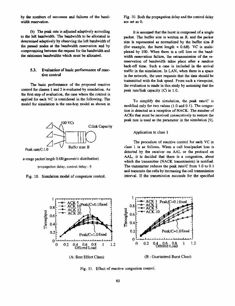
The basic performance of the proposed reactive control for classes 1 and 2 is evaluated by simulation. As the first step of evaluation, the case where the control is applied for each VC is considered in the following. The model for simulation is the one-hop model as shown in
A\" vcs C:link Capacity
Buffer size: B Peak rate/C: 1 .O
average packet length OhB(geometric distribution)
propagation delay, control delay : 0
Fig. 10. Simulation model of congestion control.
Fig. 10. Both the propagation delay and the control delay are set as 0.
It is assumed that the burst is composed of a single packet. The buffer size is written as B, and the packet size is represented as normalized by the buffer size B (for example, the burst length = 0.6B). VC is multi- plexed by 100. When there is a cell loss or the band- width reservation failure, the retransmission of the re- reservation of bandwidth takes place after a random back-off time. Such a case is included in the amval traffic in the simulation. In LAN, when there is a space in the network, the user requests that the data should be transmitted with the link speed. From such a viewpoint, the evaluation is made in this study by assuming that the peak ratellink capacity (C) is 1.0.
To simplify the simulation, the peak ratelC is modified only for two values (1 .O and 0.1). The conges- tion is detected as a reception of NACK. The number of ACKs that must be received consecutively to restore the peak rate is used as the parameter in the simulation [9].
Application to class 1
The procedure of reactive control for each VC in class 1 is as follows. When a cell lodpacket loss is detected by the receiver on AAL or the protocol on AAL, it is decided that there is a congestion, about which the transmitter (NACK transmission) is notified. The transmitter reduces the peak ratelC from 1 .O to 0.1 and transmits the cells by increasing the cell transmission interval. If the transmission succeeds for the specified
1
0.8
8 0.6 1 0.4
0.2
U s
(A: Best Effort Class)
0.6 0.8 1 1.2 Oe2 '8ffered Load
(B : Guaranteed Burst Class)
Fig. 11. Effect of reactive congestion control.
80
number of times (receptions of ACK), the process is returned to the original state.
6. Conclusions
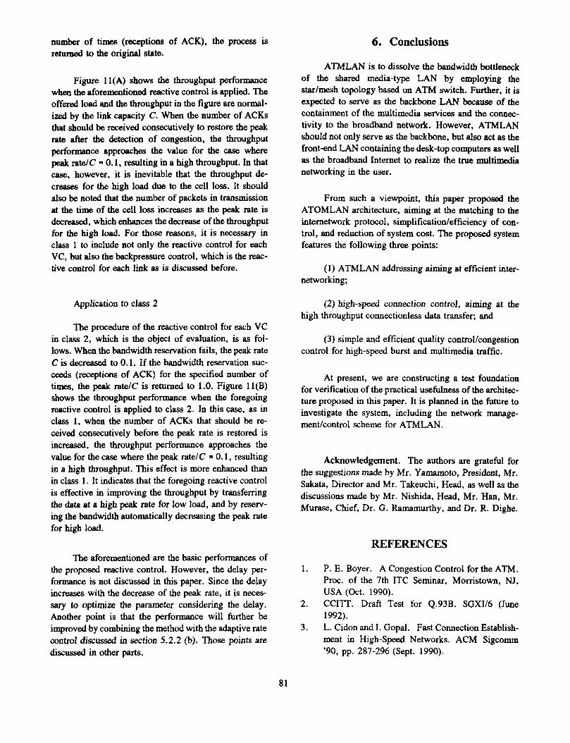
Figure 11(A) shows the throughput performance when the aforementioned reactive control is applied. The offered load and the throughput in the figure are normal- ized by the link capacity C. When the number of ACKs that should be received consecutively to restore the peak rate after the detection of congestion, the throughput performance approaches the value for the case where peak ratelC = 0.1, resulting in a high throughput. In that case, however, it is inevitable that the throughput de- creases for the high load due to the cell loss. It should also be noted that the number of packets in transmission at the time of the cell loss increases as the peak rate is decreased, which enhances the decrease of the throughput for the high load. For those reasons, it is necessary in class 1 to include not only the reactive control for each VC, but also the backpressure control, which is the reac- tive control for each link as is discussed before.
Application to class 2
The procedure of the reactive control for each VC in class 2, which is the object of evaluation, is as fol- lows. When the bandwidth reservation fails, the peak rate C is decreased to 0.1. If the bandwidth reservation suc- ceeds (receptions of ACK) for the specified number of times, the peak ratelC is returned to 1.0. Figure 11(B) shows the throughput performance when the foregoing reactive control is applied to class 2. In this case, as in class 1, when the number of ACKs that should be re- ceived consecutively before the peak rate is restored is increased, the throughput performance approaches the value for the case where the peak rate/C = 0.1, resulting in a high throughput. This effect is more enhanced than in class 1. It indicates that the foregoing reactive control is effective in improving the throughput by transfemng the data at a high peak rate for low load, and by reserv- ing the bandwidth automatically decreasing the peak rate for high load.
The aforementioned are the basic performances of the proposed reactive control. However, the delay per- formance is not discussed in this paper. Since the delay increases with the decrease of the peak rate, it is neces- sary to optimize the parameter considering the delay. Another point is that the performance will further be improved by combining the method with the adaptive rate control discussed in section 5.2.2 (b). Those points are discussed in other parts.
ATMLAN is to dissolve the bandwidth bottleneck of the shared media-type LAN by employing the star/mesh topology based on ATM switch. Further, it is expected to serve as the backbone LAN because of the containment of the multimedia services and the connec- tivity to the broadband network. However, ATMLAN should not only serve as the backbone, but also act as the front-end LAN containing the desk-top computers as well as the broadband Internet to realize the true multimedia networking in the user.
From such a viewpoint, this paper proposed the ATOMLAN architecture, aiming at the matching to the internetwork protocol, simplification/efficiency of con- trol, and duction of system cost. The proposed system features the following three points:
(1) ATMLAN addressing aiming at efficient inter- networking;
(2) high-speed connection control, aiming at the high throughput connectionless data transfer; and
(3) simple and efficient quality control/congestion control for high-speed burst and multimedia traffic.
At present, we are constructing a test foundation for verification of the practical usefulness of the architec- ture proposed in this paper. It is planned in the future to investigate the system, including the network manage- mentkontrol scheme for ATMLAN.
Acknowledgement. The authors are grateful for the suggestions made by Mr. Yamamoto, President, Mr. Sakata, Director and Mr. Takeuchi, Head, as well as the discussions made by Mr. Nishida, Head, Mr. Han, Mr. Murase, Chief, Dr. G. Ramamurthy, andDr. R. Dighe.
1.
2.
3.
REFERENCES
P. E. Boyer. A Congestion Control for the ATM. Proc. of the 7th ITC Seminar, Morristown, NJ, USA (Oct. 1990). CCITT. Draft Test for Q.93B. SGXI/6 (June 1992). L. Cidon and I. Gopal. Fast Connection Establish- ment in High-speed Networks. ACM Sigcomm '90, pp. 287-296 (Sept. 1990).
81
4.
5 .
6.
7.
8.
9.
10.
1 1 .
12.
13.
R. Colella, E. Gardner, and R. Callon. Guidelines for OSI NSAP Allocation in the Internet. RFC 1237 (July 1991). Esaki, Natsubori, and Saito. Realization of data transfer in ATMLAN. Papers of Technical Group on Information Networks, I.E.I.C.E., Japan, IN93- 6 (March 1993). Han, Suzuki, and Yamada. ATM switch with expandable buffer capacity: XATOM. Papers of Technical Group in Switching Systems Engineer- ing, I.E.I.C.E., Japan, SSE93-6 (April 1993).
on LAN. ACM SIGCOM Computer Communica- tion Review, 21, 2 (1991). ATM UNI specification draft (ver. 1 . 4). ATM Forum (April 1992). Ikeda, Murase, and Suzuki. A study of traffic control method in ATOMLAN. Papers of Techni- cal Group on Information Networks, I.E.I.C.E., Japan, IN92-189 (Feb. 1993). Iwata, Mori, and Suzuki. Protocol architecture for ATMLAN. Ibid., IN92-109 (Feb. 1993). Kubo, Saito, and Saito. Design of ATM-LAN architecture. Papers of Technical Group on Switch- ing Systems Engineering, I.E.I.C.E., Japan, SSE92-59 (Sept. 1993). T. Lyon, F. Liaw, and A. Romanow. Network Layer Architecture for ATM Networks. ATM Forum 92-1 19 (July 1992). L. Roberts, T. MacDonald, and G. Bernstein. Fast Select Virtual Circuit Routing for B-ISDN Net- works, Proc. of ISS’92, 1, p. 12 (Oct. 1992).
R. L. Frink and F. ROSS. FFOL-An FDDI Follow
14.
15.
16.
17.
18.
19.
20.
21.
22.
AUTHORS
M. D. Schroeder and A. Birrell. Autonet: A High-speed, Self-Configuring Local Area Network Using Point-to-Point Links. IEEE J. Sel. Areas
N. Sugaya, H. Nagano. A 1.28-Gbps 16 x 16 CMOS Chip for an Output-Buffer ATM Switch. 1992 Symposium on VLSI Circuits, pp. 76-77 (June 1992). H. Suzuki. Addressing and Routing for Private and Public ATM Networks. ATM-Forum 92-302 (Dec. 1992). H. Suzuki and F. Liaw. Routing Schemes for multiple network address types. ATM-Forum 93- 396 (Jan. 1993). H. Suzuki and F. A. Tobagi. Fast Bandwidth Reservation Scheme with Multilink and Multipath Routing in ATM Networks. Infocom’92, 10A, 2 (May 1992). Taniguchi, Nishida, and Suzuki. Architecture and performance evaluation for internet node processor in high-speed internet environment. Trans. (B-I) I.E.I.C.E., Japan, J76-B-I, 11 , pp. 859-867 (Nov. 1993). C. Topolcic. Experimental Internet Stream Proto- col: Version 2 (ST-11). RFC 1190 (Oct. 1990). G. Ramamurthy and R. Dighe. Access Control Functions for ATMLAN. ATM Forum 93-428 (Feb. 1993). M. W e d , 0. A. Magd, and H. Gilbert. Traffic Management for B-ISDN Services. IEEE Network Mag. (Sept. 1992).
commun., 9, 8 (Oct. 1991).
Hiroshi Suzuki received his B.S. and M.S. degrees in 1984 and 1986, respectively, from Osaka University, and his Ph.D. later. He then affiliated with NEC C&C System Lab. He was a Visiting Researcher during 1990-199 1 at Stanford University, U.S.A. He is engaged in research on broadband ISDN, high-speed packet switching, traffic control, and high- speed computer network architecture. He is a member of IEEE.
82
AUTHORS (from left to right, continued)
Atsushi Iwata received his B.S. and M.S. degrees in 1988 and 1990, respectively, from the University of Tokyo and affiliated with NEC C&C System Lab. He is engaged in research on ATM communication system and computer communication protocol, and presently in research on architecture and performance evaluation of high-speed computer network, such as ATM-LAN. He is a member of IEEE.
Chinatsu Ikeda received her B.S. degree in 1987 from the Department of Electrical Engineering, Fac. Sci. Tech., Keio University, and affiliated with NEC C&C System Lab. She is engaged in research on LAN architecture, performance evaluation method for communication system, and traffic control in high-speed network.
Naoki Mori received his B.S. and M.S. degrees in 1990 and 1992, respectively, from Kyoto University and affiliated with NEC C&C System Lab. Presently, he is engaged in research on network protocol, ATM-LAN architecture and performance evaluation of protocol.
83