Embed Size (px)
Citation preview

42080B-MCU-10/2013
USER GUIDE
Atmel PROTO1 Xplained Pro
Preface
The Atmel® PROTO1 Xplained Pro extension board is a development boardthat can be used to prototype small circuits and easy connect it to Xplained ProMCU boards through one of the standard extension headers. It includes an IDchip and will be recognized by Atmel Studio. It can also be used to interfaceolder Xplained top-modules like sensor boards. There is a separate connectoravailable to connect external power to a Xplained Pro series evaluation kits. Thissection can be separated from the prototype section to be used standalone ornot at all.
Atmel PROTO1 Xplained Pro [USER GUIDE]42080B-MCU-10/2013
2
Table of Contents
Preface .......................................................................................... 1
1. Introduction .............................................................................. 31.1. Features .............................................................................. 31.2. Kit Overview ......................................................................... 3
2. Getting Started ........................................................................ 52.1. Three Steps to Start Exploring the Atmel Xplained Pro Platform ...... 52.2. Connecting PROTO1 Xplained Pro to the Xplained Pro MCU
Board. ................................................................................. 52.3. Documentation for Atmel PROTO1 Xplained Pro ......................... 5
3. Xplained Pro ............................................................................ 63.1. Hardware Identification System ................................................ 63.2. Standard Headers and Connectors ........................................... 6
3.2.1. Xplained Pro Standard Extension Header ...................... 63.2.2. Power header ........................................................... 7
4. Hardware user guide .............................................................. 84.1. Connectors .......................................................................... 8
4.1.1. PROTO1 Xplained Pro Extension Headers ..................... 84.1.2. Power Header .......................................................... 84.1.3. External Power Terminal Block Header .......................... 8
4.2. PROTO1 Xplained Pro ID System ............................................ 94.3. Connecting the PROTO1 Xplained Pro .................................... 10
4.3.1. Connecting Xplained Extension Boards ........................ 114.3.2. Using PROTO1 Xplained Pro With a Solderless
Breadboard ............................................................ 11
5. Hardware Revision History and Knonwn Issues ................... 135.1. Identifying Product ID and Revision ......................................... 135.2. Revision 2 .......................................................................... 13
6. Document revision history ..................................................... 14
7. Evaluation board/kit important notice .................................... 15
Atmel PROTO1 Xplained Pro [USER GUIDE]42080B-MCU-10/2013
3
1. Introduction
1.1 Features
● Prototyping area with 10 x 20 = 200 PADs
● 100mil spacing to ease through-hole component prototyping
● Square PADs to ease SMD passive component prototyping
● Fits mini solderless breadboards for fast and simple prototyping
● Xplained Pro hardware identification system
● Can be used as an vertical extender for Xplained Pro standard extionsion modules
● Support for Xplained series extension modules
1.2 Kit OverviewThe Atmel PROTO1 Xplained Pro board is a generic prototyping extension board for the Xplained Pro platform.It connects to any standard extension header on any Xplained Pro MCU board and thus is offers an easyway to do prototyping with the Xplained Pro platform. It can be used to prototype small designs that canbe connected to the Xplained Pro MCU series of kits. The prototype area consist of 200 free square padswith 100mil (2.54mm) spacing that can be used to protoype both through-hole components as well as SMDcomponents like resistors, capacitors, inductors... The protoyping area is marked with letters and numbers onboth sides of the board so it is easy to identify each pad with a coordinate to make precise connections. Powerin the form of GND and VCC_TARGET (is distributed horizontally along the lower side of the prototype for easyconnection across the board. The prototyping area offers also space to fit a solderless breadboard on top. Apopular size of these boards is 45mm x 35mm and provides 170 solderless points.
The top section of the board is a break-away section that can be used to connect external power to theXplained Pro MCU bord with a screw terminal block. It also distributes GND, VCC_TARGET, and VCC_USB(+5V) from the Xplained Pro MCU board that can easily be connected to the prototyping area.
The lower section of the board has a right angled header on the left side that connects to Xplained Pro MCUboards, a prototyping area in the middle and another connector on the right side that provides easy access tothe extension header signals. The vertical header on the right hand side can be used to connect the extensionsignals to the prototyping area or to connect extension modules of the Xplained platform e.g. sensor boards, orthe RZ600 radio kit. More information on how to connect Xplained extensions is available in the hardware usersguide section of this guide.
The Atmel PROTO1 Xplained Pro supports the Xplained Pro hardware identification system.

Atmel PROTO1 Xplained Pro [USER GUIDE]42080B-MCU-10/2013
4
Figure 1-1. PROTO1 Xplained Pro Extension Board, Top View.
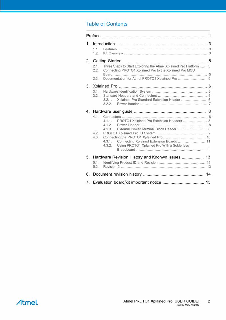
Figure 1-2. PROTO1 Xplained Pro Extension Board, Bottom View.

Atmel PROTO1 Xplained Pro [USER GUIDE]42080B-MCU-10/2013
5
2. Getting Started
2.1 Three Steps to Start Exploring the Atmel Xplained Pro Platform
1. Download and install Atmel Studio.
2. Launch Atmel Studio.
3. Connect PROTO1 Xplained Pro to an Xplained Pro MCU board and connect a USB cable to DEBUG USBport on the Xplained Pro MCU board.
2.2 Connecting PROTO1 Xplained Pro to the Xplained Pro MCU Board.To start using the PROTO1 Xplained Pro extension board you will need an Xplained Pro MCU board with atleast one standard 20-pin extension header. The PROTO1 Xplained Pro can be connected to any of theseextension headers. After the PROTO1 Xplained Pro has been connected to an extension header the XplainedPro MCU board can be powered in the normal way as described in the help for this kit.
Warning If any modifications are done to the PROTO1 Xplained Pro prototype circuit, please check thatthere are no short-circuits on the power lines before connecting it to the Xplained Pro MCU boardin order to avoid any damage.
2.3 Documentation for Atmel PROTO1 Xplained ProThe following list contains links to the most relevant documents and software for the PROTO1 Xplained Pro.
1. Xplained Pro products 1 - Atmel Xplained Pro is a series of small-sized and easy-to-use evaluation kitsfor 8- and 32-bit Atmel microcontrollers. It consists of a series of low cost MCU boards for evaluation anddemonstration of features and capabilities of different MCU families.
2. PROTO1 Xplained Pro User Guide 2 - PDF version of this User Guide.
3. PROTO1 Xplained Pro Design Documentation 3 - Package containing schematics, BOM, assemblydrawings, 3D plots, layer plots etc.
4. Atmel Studio 4 - Free Atmel IDE for development of C/C++ and assembler code for Atmelmicrocontrollers.
1 http://www.atmel.com/XplainedPro2 http://www.atmel.com/Images/Atmel-42080-PROTO1-Xplained-Pro_User-Guide.pdf3 http://www.atmel.com/Images/Atmel-42080-PROTO1-Xplained-Pro_User-Guide.zip4 http://www.atmel.com/atmelstudio

Atmel PROTO1 Xplained Pro [USER GUIDE]42080B-MCU-10/2013
6
3. Xplained ProXplained Pro is an evaluation platform that provides the full Atmel microcontroller experience. The platformconsists of a series of Microcontroller (MCU) boards and extension boards that are integrated with AtmelStudio, have Atmel Software Framework (ASF) drivers and demo code, support data streaming and more.Xplained Pro MCU boards support a wide range of Xplained Pro extension boards that are connected througha set of standardized headers and connectors. Each extension board has an identification (ID) chip to uniquelyidentify which boards are mounted on a Xplained Pro MCU board. This information is used to present relevantuser guides, application notes, datasheets and example code through Atmel Studio. Available Xplained ProMCU and extension boards can be purchased in the Atmel Web Store1.
3.1 Hardware Identification SystemAll Xplained Pro compatible extension boards have an Atmel ATSHA204 CryptoAuthentication™ chip mounted.This chip contains information that identifies the extension with its name and some extra data. When anXplained Pro extension board is connected to an Xplained Pro MCU board the information is read and sentto Atmel Studio. The Atmel Kits extension, installed with Atmel Studio, will give relevant information, codeexamples and links to relevant documents. Table 3-1, “Xplained Pro ID Chip Content” on page 6 shows thedata fields stored in the ID chip with example content.
Table 3-1. Xplained Pro ID Chip Content
Data Field Data Type Example ContentManufacturer ASCII string Atmel’\0’
Product Name ASCII string Segment LCD1 Xplained Pro’\0’
Product Revision ASCII string 02’\0’
Product Serial Number ASCII string 1774020200000010’\0’
Minimum Voltage [mV] uint16_t 3000
Maximum Voltage [mV] uint16_t 3600
Maximum Current [mA] uint16_t 30
3.2 Standard Headers and Connectors
3.2.1 Xplained Pro Standard Extension HeaderAll Xplained Pro kits have one or more dual row, 20-pin, 100mil extension headers. Xplained Pro MCU boardshave male headers while Xplained Pro extensions have their female counterparts. Note that all pins are notalways connected. However, all the connected pins follow the defined pin-out described in Table 3-2, “XplainedPro Extension Header” on page 6. The extension headers can be used to connect a wide variety ofXplained Pro extensions to Xplained Pro MCU boards and to access the pins of the target MCU on XplainedPro MCU board directly.
Table 3-2. Xplained Pro Extension Header
Pin number Name Description1 ID Communication line to the ID chip on extension board.
2 GND Ground.
3 ADC(+) Analog to digital converter , alternatively positive part ofdifferential ADC.
4 ADC(-) Analog to digital converter , alternatively negative part ofdifferential ADC.
5 GPIO1 General purpose I/O.
6 GPIO2 General purpose I/O.
7 PWM(+) Pulse width modulation , alternatively positive part ofdifferential PWM.
8 PWM(-) Pulse width modulation , alternatively positive part ofdifferential PWM.
1 http://store.atmel.com/

Atmel PROTO1 Xplained Pro [USER GUIDE]42080B-MCU-10/2013
7
Pin number Name Description9 IRQ/GPIO Interrupt request line and/or general purpose I/O.
10 SPI_SS_B/GPIO Slave select for SPI and/or general purpose I/O.
11 TWI_SDA Data line for two-wire interface. Always implemented, bustype.
12 TWI_SCL Clock line for two-wire interface. Always implemented, bustype.
13 USART_RX Receiver line of Universal Synchronous and Asynchronousserial Receiver and Transmitter.
14 USART_TX Transmitter line of Universal Synchronous andAsynchronous serial Receiver and Transmitter.
15 SPI_SS_A Slave select for SPI. Should be unique if possible.
16 SPI_MOSI Master out slave in line of Serial peripheral interface. Alwaysimplemented, bus type.
17 SPI_MISO Master in slave out line of Serial peripheral interface. Alwaysimplemented, bus type.
18 SPI_SCK Clock for Serial peripheral interface. Always implemented,bus type.
19 GND Ground.
20 VCC Power for extension board.
3.2.2 Power headerThe right-angled female power header (marked PWR) will connect to a similar header if the PROTO1 XplainedPro is connected to the EXT1 extension header on the the Xplained Pro MCU board. It can be used to powerthe Xplained Pro MCU board from an external source or to get internal power from the Xplaiend Pro MCUboard to the PROTO1 Xplained Pro

Atmel PROTO1 Xplained Pro [USER GUIDE]42080B-MCU-10/2013
8
4. Hardware user guide
4.1 ConnectorsThis chapter describes the implementation of the relevant connectors and headers on PROTO1 Xplained Proand their connection to the external devices. The tables of connections in this chapter also describes whichsignals are shared between the headers and on-board functionality.
4.1.1 PROTO1 Xplained Pro Extension HeadersThe PROTO1 Xplained Pro has two 20-pin headers. One is angled (left side of the board) and is intended to beconnected to a Xplained Pro MCU board, standard extension header. The other is a vertical header (right sideof the board) that can be used to connect signals to the prototype area or to attach other extension modules toit. The signals are identical on both, except for the ID signal, which is slightly different. The rest of the signalsfollow the standard extension header pinout specified in Xplained Pro Standard Extension Header on page 6.The different ID signals are described in section “PROTO1 Xplained Pro ID System” on page 9.
Figure 4-1. Extension Header Connector.
4.1.2 Power HeaderThe four pin power header on the PROTO1 Xplained Pro extension board is used to probe the voltage on theboard. The pins of the header are marked in silk screen with VCC for target voltage and GND for ground.
Note The two pin power header should not be used to apply power to the PROTO1 Xplained Pro. Theboard will get power from the Xplained Pro MCU board through the 20-pin extension connector.
Table 4-1. Power Header.
Silk screen marking DescriptionVCC Target voltage, main voltage of the PROTO1 Xplained Pro extension board
GND Ground
EP5V0 External 5.0V supplied to the Xplained Pro MCU board
VP5V0 VCC_USB,
4.1.3 External Power Terminal Block HeaderThe PROTO1 Xplained Pro features a two pin terminal block header to connect external power to the board.To connect a cable to it, just insert it (remove the insulation from the end first) through the holes at the bottom

Atmel PROTO1 Xplained Pro [USER GUIDE]42080B-MCU-10/2013
9
entry of the connector. An internal springblade will lock the wire in place. To release it again, insert a smallscrewdriver or similar into the top hole to release the tension of the springblade and pull the wire out. This isshown in Table 4-3, “Power Connector.” on page 9.
Table 4-2. Power Connector.
Silk screen marking Pin on Power connectorEP5V0 1
GND 2
Table 4-3. Power Connector.
4.2 PROTO1 Xplained Pro ID SystemThe PROTO1 Xplained Pro board has the Xplained Pro hardware identification system implemented. Whenthe board is connected via an Atmel Xplained Pro MCU board to Atmel Studio it will be identified and relevantinformation like the user guide will be shown. By default the ID device on the board is connected to the rightangled extension header and the ID X pin of the vertical extension header on the right side of the board isunconnected. It is however possible to connect the ID X signal to the right angled extension header with thehardware changes described below. This makes it possible to use the PROTO1 Xplained Pro as an right angleextender for extension boards and Atmel Studio vill recognize their ID. In order to do so, the PROTO1 XplainedPro ID needs to be disconnected and the ID X signal needs to be connected. To disconnect the PROTO1Xplained Pro ID just cut the cut-strap marked as ID PROTO1 (see Figure 4-2, “ID PROTO1.” on page 9) onthe bottom side of the PCB.
Figure 4-2. ID PROTO1.
To connect the ID X signal, just solder a zero ohm resistor or a piece of wire to the open strap marked as ID X(see Figure 4-3, “ID X.” on page 9) on the bottom side of the PCB.
Figure 4-3. ID X.

Atmel PROTO1 Xplained Pro [USER GUIDE]42080B-MCU-10/2013
10
Now any connected Xplained Pro extension modules that are plugged into the vertical extension header onthe right side of the board will be detected by Atmel Studio, the PROTO1 Xplained Pro extension board will notlonger be detected.
4.3 Connecting the PROTO1 Xplained ProThe lower part of the PROTO1 Xplained Pro board can be connected to all Xplained Pro MCU evalutation kitsstandard extension headers. If the upper break-off part, containing the additional power section, should beused, it is required to connect the board to the EXT1 header in order to connect to the Power header as well(see Figure 4-4, “Example Connection.” on page 10). To break off the upper section of the board break italong the V-CUT score line across the PCB.
Figure 4-4. Example Connection.
The connection indicated below (See Figure 4-5, “Not Recommended PROTO1 Xplained ProConnection.” on page 10) may cause the power plug to short some of the EXT1 pins if it is connectedexternally. To avoid this, either move the PROTO1 Xplained Pro to another extension connector or break awaythe power section.
Figure 4-5. Not Recommended PROTO1 Xplained Pro Connection.

Atmel PROTO1 Xplained Pro [USER GUIDE]42080B-MCU-10/2013
11
Note Note that any remaining mousebite residues should be filed or cut away for optimum fit.
4.3.1 Connecting Xplained Extension BoardsIt is also possible to interface Xplained top-modules via the PROTO1 Xplained Pro board. The signal layout onthe extension connector below the white line, i.e. pins 11 - 20 is identical to the J1 connector (communicationconnector) on the Xplained series MCU boards (see Figure 4-6, “External Connector.” on page 11).
Figure 4-6. External Connector.
So for Xplained series top-modules that only uses this connector can be attached. Note that the extensionconnector on the Xplained Pro MCU board might not have all signals available due to lack of pin resources.This needs to be checked for each case. A mounting example is shown in the Figure 4-7, “Xplained SeriesSensor Board Mounted on PROTO1 Xplained Pro” on page 11 with a sensor board.
Figure 4-7. Xplained Series Sensor Board Mounted on PROTO1 Xplained Pro
4.3.2 Using PROTO1 Xplained Pro With a Solderless BreadboardIt is possible to mount a 170 Tie-points solderless breadboard (size 47mm x 35mm) on to the prototype sectionon the PROTO1 Xplained Pro board to ease prototyping (see Figure 4-8, “Solderless Breadboard Mounted on

Atmel PROTO1 Xplained Pro [USER GUIDE]42080B-MCU-10/2013
12
PROTO1 Xplained Pro.” on page 12). It lacks any GND/VCC rails so they needs to be connected directly.These boards can be found at a low cost from lots of vendors on internet.
Figure 4-8. Solderless Breadboard Mounted on PROTO1 Xplained Pro.
Atmel PROTO1 Xplained Pro [USER GUIDE]42080B-MCU-10/2013
13
5. Hardware Revision History and Knonwn Issues
5.1 Identifying Product ID and RevisionThe revision and product identifier of Xplained Pro boards can be found in two ways, through Atmel Studio orby looking at the sticker on the bottom side of the PCB.By connecting a Xplained Pro MCU board to a computer with Atmel Studio running, an information window willpop up. The first six digits of the serial number, which is listed under kit details, contain the product identifierand revision. Information about connected Xplained Pro extension boards will also appear in the Atmel Kitswindow.The same information can be found on the sticker on the bottom side of the PCB. Most kits will print theidentifier and revision in plain text as A09-nnnn\rr where nnnn is the identifier and rr is the revision. Boards withlimited space have a sticker with only a QR-code which contains a serial number string.The serial number string has the following format:
"nnnnrrssssssssss" n = product identifier r = revision s = serial number
The kit identifier for PROTO1 Xplained Pro is 1890.
5.2 Revision 2Revision 2 of PROTO1 Xplained Pro is the initial released version.PROTO1 Xplained Pro boards with a serial number that ends with a number lower than 19048 may have awrong revision programmed into the Xplained Pro ID chip. This will only affect the information displayed by theAtmel Kits extension in Atmel Studio. It will not affect the operation of the board.

Atmel PROTO1 Xplained Pro [USER GUIDE]42080B-MCU-10/2013
14
6. Document revision history
Documentrevision
Date Comment
42080B 09/2013 Added errata about revision 2 of the board.
42080A 25/02/2013 First release
Atmel PROTO1 Xplained Pro [USER GUIDE]42080B-MCU-10/2013
15
7. Evaluation board/kit important notice
This evaluation board/kit is intended for use for FURTHER ENGINEERING, DEVELOPMENT,DEMONSTRATION, OR EVALUATION PURPOSES ONLY. It is not a finished product and may not (yet)comply with some or any technical or legal requirements that are applicable to finished products, including,without limitation, directives regarding electromagnetic compatibility, recycling (WEEE), FCC, CE or UL(except as may be otherwise noted on the board/kit). Atmel supplied this board/kit "AS IS," without anywarranties, with all faults, at the buyer's and further users' sole risk. The user assumes all responsibilityand liability for proper and safe handling of the goods. Further, the user indemnifies Atmel from all claimsarising from the handling or use of the goods. Due to the open construction of the product, it is the user'sresponsibility to take any and all appropriate precautions with regard to electrostatic discharge and any othertechnical or legal concerns.EXCEPT TO THE EXTENT OF THE INDEMNITY SET FORTH ABOVE, NEITHER USER NORATMEL SHALL BE LIABLE TO EACH OTHER FOR ANY INDIRECT, SPECIAL, INCIDENTAL, ORCONSEQUENTIAL DAMAGES.No license is granted under any patent right or other intellectual property right of Atmel covering or relatingto any machine, process, or combination in which such Atmel products or services might be or are used.

Atmel Corporation 1600 Technology Drive, San Jose, CA 95110 USA T: (+1)(408) 441.0311 F: (+1)(408) 436.4200 | www.atmel.com
© 2013 Atmel Corporation. All rights reserved. / Rev.: 42080B-MCU-10/2013
Atmel®, Atmel logo and combinations thereof, Enabling Unlimited Possibilities®, and others are registered trademarks or trademarks of AtmelCorporation or its subsidiaries. Other terms and product names may be trademarks of others.
Disclaimer: The information in this document is provided in connection with Atmel products. No license, express or implied, by estoppel or otherwise, to any intellectual property right is grantedby this document or in connection with the sale of Atmel products. EXCEPT AS SET FORTH IN THE ATMEL TERMS AND CONDITIONS OF SALES LOCATED ON THE ATMEL WEBSITE,ATMEL ASSUMES NO LIABILITY WHATSOEVER AND DISCLAIMS ANY EXPRESS, IMPLIED OR STATUTORY WARRANTY RELATING TO ITS PRODUCTS INCLUDING, BUT NOTLIMITED TO, THE IMPLIED WARRANTY OF MERCHANTABILITY, FITNESS FOR A PARTICULAR PURPOSE, OR NON-INFRINGEMENT. IN NO EVENT SHALL ATMEL BE LIABLE FORANY DIRECT, INDIRECT, CONSEQUENTIAL, PUNITIVE, SPECIAL OR INCIDENTAL DAMAGES (INCLUDING, WITHOUT LIMITATION, DAMAGES FOR LOSS AND PROFITS, BUSINESSINTERRUPTION, OR LOSS OF INFORMATION) ARISING OUT OF THE USE OR INABILITY TO USE THIS DOCUMENT, EVEN IF ATMEL HAS BEEN ADVISED OF THE POSSIBILITY OFSUCH DAMAGES. Atmel makes no representations or warranties with respect to the accuracy or completeness of the contents of this document and reserves the right to make changes tospecifications and products descriptions at any time without notice. Atmel does not make any commitment to update the information contained herein. Unless specifically provided otherwise,Atmel products are not suitable for, and shall not be used in, automotive applications. Atmel products are not intended, authorized, or warranted for use as components in applications intendedto support or sustain life.


![Atmel AT02657: XMEGA-E5 Xplained Software User Guideww1.microchip.com/downloads/en/AppNotes/Atmel... · Atmel AT02657: XMEGA-E5 Xplained Software User Guide [APPLICATION NOTE] 42085A−AVR−04/2013](https://img.pdfslide.net/doc/110x75/5f88ba81f6b36722b04d705d/atmel-at02657-xmega-e5-xplained-software-user-atmel-at02657-xmega-e5-xplained.jpg)


![Atmel SAM R21 Xplained Pro (USER GUIDE) - Mouser Electronics · Atmel SAM R21 Xplained Pro [USER GUIDE] 42243A-MCU-02/2014 6 3. Xplained Pro Xplained Pro is an evaluation platform](https://img.pdfslide.net/doc/110x75/5c7395a209d3f2123b8b83c4/atmel-sam-r21-xplained-pro-user-guide-mouser-atmel-sam-r21-xplained-pro.jpg)