Embed Size (px)
Citation preview
42220A-MCU-02/2014
USER GUIDE
Atmel SAM D21 Xplained Pro
Preface
The Atmel® SAM D21 Xplained Pro evaluation kit is a hardware platform toevaluate the ATSAMD21J18A microcontroller.Supported by the Atmel Studio integrated development platform, the kit provideseasy access to the features of the Atmel ATSAMD21J18A and explains how tointegrate the device in a custom design.The Xplained Pro MCU series evaluation kits include an on-board EmbeddedDebugger, and no external tools are necessary to program or debug theATSAMD21J18A.The Xplained Pro extension kits offers additional peripherals to extend thefeatures of the board and ease the development of custom designs.
Atmel SAM D21 Xplained Pro [USER GUIDE]42220A-MCU-02/2014
2
Table of Contents
Preface .......................................................................................... 1
1. Introduction .............................................................................. 31.1. Features .............................................................................. 31.2. Kit Overview ......................................................................... 3
2. Getting Started ........................................................................ 52.1. Quick-start ........................................................................... 52.2. Connecting the Kit ................................................................. 52.3. Design Documentation and Related Links .................................. 5
3. Xplained Pro ............................................................................ 63.1. Embedded Debugger ............................................................. 63.2. Hardware Identification System ................................................ 63.3. Power Supply ....................................................................... 7
3.3.1. Measuring SAM D21 Power Consumption ...................... 73.4. Standard Headers and Connectors ........................................... 7
3.4.1. Xplained Pro Standard Extension Header ...................... 73.4.2. Xplained Pro Power Header ........................................ 8
4. Hardware User Guide ........................................................... 104.1. Connectors ......................................................................... 10
4.1.1. I/O Extension Headers ............................................. 104.2. Peripherals ......................................................................... 11
4.2.1. Crystal ................................................................... 114.2.2. Mechanical Buttons .................................................. 124.2.3. LED ...................................................................... 124.2.4. USB ...................................................................... 124.2.5. Serial Flash ............................................................ 12
4.3. Embedded Debugger Implementation ...................................... 134.3.1. Serial Wire Debug ................................................... 134.3.2. Virtual COM Port ..................................................... 134.3.3. Atmel Data Gateway Interface ................................... 13
5. Hardware Revision History and Known Issues ..................... 145.1. Identifying Product ID and Revision ......................................... 145.2. Revision 2 .......................................................................... 14
6. Document Revision History ................................................... 15
7. Evaluation Board/Kit Important Notice .................................. 16
Atmel SAM D21 Xplained Pro [USER GUIDE]42220A-MCU-02/2014
3
1. Introduction
1.1 Features
● Atmel ATSAMD21J18A microcontroller
● Embedded debugger (EDBG)
● USB interface
● Programming and debugging on board SAM D21 through Serial Wire Debug (SWD)
● Virtual COM-port interface to target via UART
● Atmel Data Gateway Interface (DGI) to target via SPI and TWI
● Four GPIOs connected to target for code instrumentation
● Digital I/O
● Two mechanical buttons (user and reset button)
● One user LED
● Three extension headers
● Three possible power sources
● External power
● Embedded debugger USB
● Target USB
● 32kHz crystal
● USB interface, device and reduced host mode
● 8Mbit Serial Flash
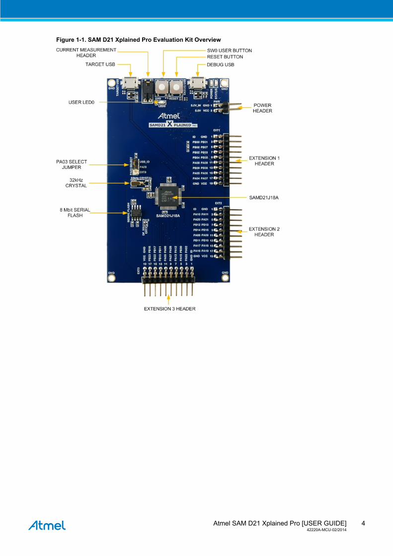
1.2 Kit OverviewThe Atmel SAM D21 Xplained Pro evaluation kit is a hardware platform to evaluate the Atmel ATSAMD21J18A.
The kit offers a set of features that enables the ATSAMD21J18A user to get started using the ATSAMD21J18Aperipherals right away and to get an understanding of how to integrate the device in their own design.
Atmel SAM D21 Xplained Pro [USER GUIDE]42220A-MCU-02/2014
4
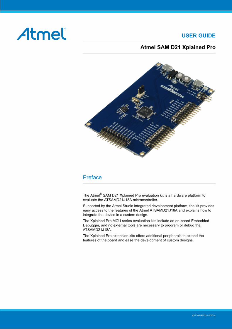
Figure 1-1. SAM D21 Xplained Pro Evaluation Kit Overview
Atmel SAM D21 Xplained Pro [USER GUIDE]42220A-MCU-02/2014
5
2. Getting Started
2.1 Quick-start3 Steps to start exploring the Atmel Xplained Pro Platform
● Download and install Atmel Studio1
● Launch Atmel Studio
● Connect a Micro-B cable to the DEBUG USB port
2.2 Connecting the KitWhen connecting Atmel SAM D21 Xplained Pro to your computer for the first time, the operating system will doa driver software installation. The driver file supports both 32-bit and 64-bit versions of Microsoft® Windows®
XP and Windows 7.Once connected the green power LED will be lit and Atmel Studio will autodetect which Xplained Proevaluation- and extension kit(s) that's connected. You'll be presented with relevant information like datasheetsand kit documentation. You also have the option to launch Atmel Software Framework (ASF) exampleapplications. The target device is programmed and debugged by the on-board Embedded Debugger andno external programmer or debugger tool is needed. Refer to the Atmel Studio user guide2 for informationregarding how to compile and program the kit.
2.3 Design Documentation and Related LinksThe following list contains links to the most relevant documents and software for SAM D21 Xplained Pro.
1. Xplained Pro products 3 - Atmel Xplained Pro is a series of small-sized and easy-to-use evaluation kitsfor 8- and 32-bit Atmel microcontrollers. It consists of a series of low cost MCU boards for evaluation anddemonstration of features and capabilities of different MCU families.
2. SAM D21 Xplained Pro User Guide 4 - PDF version of this User Guide.
3. SAM D21 Xplained Pro Design Documentation 5 - Package containing schematics, BOM, assemblydrawings, 3D plots, layer plots etc.
4. EDBG User Guide 6 - User guide containing more information about the onboard Embedded Debugger.
5. Atmel Studio 7 - Free Atmel IDE for development of C/C++ and assembler code for Atmelmicrocontrollers.
6. IAR Embedded Workbench® 8 for ARM®. This is a commercial C/C++ compiler that is available for ARM.There is a 30 day evaluation version as well as a code size limited kick-start version available from theirwebsite. The code size limit is 16KB for devices with M0, M0+ and M1 cores and 32KB for devices withother cores.
7. Atmel sample store 9 - Atmel sample store where you can order samples of devices.
1 http://www.atmel.com/atmelstudio2 http://www.atmel.com/atmelstudio3 http://www.atmel.com/XplainedPro4 http://www.atmel.com/Images/Atmel-42220-SAMD21-Xplained-Pro_User-Guide.pdf5 http://www.atmel.com/Images/Atmel-42220-SAMD21-Xplained-Pro_User-Guide.zip6 http://www.atmel.com/Images/Atmel-42096-Microcontrollers-Embedded-Debugger_User-Guide.pdf7 http://www.atmel.com/atmelstudio8 http://www.iar.com/en/Products/IAR-Embedded-Workbench/ARM/9 http://www.atmel.com/system/samplesstore
Atmel SAM D21 Xplained Pro [USER GUIDE]42220A-MCU-02/2014
6
3. Xplained ProXplained Pro is an evaluation platform that provides the full Atmel microcontroller experience. The platformconsists of a series of Microcontroller (MCU) boards and extension boards that are integrated with AtmelStudio, have Atmel Software Framework (ASF) drivers and demo code, support data streaming and more.Xplained Pro MCU boards support a wide range of Xplained Pro extension boards that are connected througha set of standardized headers and connectors. Each extension board has an identification (ID) chip to uniquelyidentify which boards are mounted on a Xplained Pro MCU board. This information is used to present relevantuser guides, application notes, datasheets and example code through Atmel Studio. Available Xplained ProMCU and extension boards can be purchased in the Atmel Web Store1.
3.1 Embedded DebuggerThe SAM D21 Xplained Pro contains the Atmel Embedded Debugger (EDBG) for on-board debugging. TheEDBG is a composite USB device of three interfaces; a debugger, Virtual COM Port and Data GatewayInterface (DGI).In conjunction with Atmel Studio, the EDBG debugger interface can program and debug the ATSAMD21J18A.On the SAM D21 Xplained Pro, the SWD interface is connected between the EDBG and the ATSAMD21J18A.The Virtual COM Port is connected to a UART port on the ATSAMD21J18A (see section “Embedded DebuggerImplementation” on page 13 for pinout), and provides an easy way to communicate with the targetapplication through simple terminal software. It offers variable baud rate, parity and stop bit settings. Note thatthe settings on the target device UART must match the settings given in the terminal software.The DGI consists of several physical data interfaces for communication with the host computer. See section“Embedded Debugger Implementation” on page 13 for available interfaces and pinout. Communicationover the interfaces are bidirectional. It can be used to send events and values from the ATSAMD21J18A, oras a generic printf-style data channel. Traffic over the interfaces can be timestamped on the EDBG for moreaccurate tracing of events. Note that timestamping imposes an overhead that reduces maximal throughput. TheDGI uses a proprietary protocol, and is thus only compatible with Atmel Studio.The EDBG controls two LEDs on SAM D21 Xplained Pro, a power LED and a status LED. Table 3-1, “EDBGLED Control” on page 6 shows how the LEDs are controlled in different operation modes.
Table 3-1. EDBG LED Control
Operation mode Power LED Status LEDNormal operation Power LED is lit when power is
applied to the board.Activity indicator, LED flashesevery time something happens onthe EDBG.
Bootloader mode (idle) The power LED and the status LED blinks simultaneously.
Bootloader mode (firmwareupgrade)
The power LED and the status LED blinks in an alternating pattern.
For further documentation on the EDBG, see the EDBG User Guide2.
3.2 Hardware Identification SystemAll Xplained Pro compatible extension boards have an Atmel ATSHA204 CryptoAuthentication™ chip mounted.This chip contains information that identifies the extension with its name and some extra data. When anXplained Pro extension board is connected to an Xplained Pro MCU board the information is read and sentto Atmel Studio. The Atmel Kits extension, installed with Atmel Studio, will give relevant information, codeexamples and links to relevant documents. Table 3-2, “Xplained Pro ID Chip Content” on page 6 shows thedata fields stored in the ID chip with example content.
Table 3-2. Xplained Pro ID Chip Content
Data Field Data Type Example ContentManufacturer ASCII string Atmel’\0’
Product Name ASCII string Segment LCD1 Xplained Pro’\0’
Product Revision ASCII string 02’\0’
Product Serial Number ASCII string 1774020200000010’\0’
1 http://store.atmel.com/CBC.aspx?q=c:1001132 http://www.atmel.com/Images/Atmel-42096-Microcontrollers-Embedded-Debugger_User-Guide.pdf
Atmel SAM D21 Xplained Pro [USER GUIDE]42220A-MCU-02/2014
7
Data Field Data Type Example ContentMinimum Voltage [mV] uint16_t 3000
Maximum Voltage [mV] uint16_t 3600
Maximum Current [mA] uint16_t 30
3.3 Power SupplyThe SAM D21 Xplained Pro kit can be powered either by USB or by an external power source through the 4-pin power header, marked PWR. This connector is described in “Xplained Pro Power Header” on page 8.The available power sources and specifications are listed in Table 3-3, “Power Sources for SAM D21 XplainedPro” on page 7.
Table 3-3. Power Sources for SAM D21 Xplained Pro
Power input Voltage requirements Current requirements Connector markingExternal power 5V ± 2 % (± 100mV) for
USB host operation.4.3V to 5.5V if USB hostoperation is not required
Recommendedminimum is 1A tobe able to provideenough current forconnected USBdevices and the boarditself. Recommendedmaximum is 2A dueto the input protectionmaximum currentspecification.
PWR
Embedded debuggerUSB
4.4V to 5.25V(according to USB spec)
500mA (according toUSB spec)
DEBUG USB
Target USB 4.4V to 5.25V(according to USB spec)
500mA (according toUSB spec)
TARGET USB
The kit will automatically detect which power sources are available and choose which one to use according tothe following priority:
1. External power
2. Embedded debugger USB
3. Target USB
Note External power is required when the 500mA through the USB connector is not enough to power aconnected USB device in a USB host application.
3.3.1 Measuring SAM D21 Power ConsumptionAs part of an evaluation of the SAM D21 it can be of interest to measure its power consumption. Because thedevice has a separate power plane (VCC_MCU_P3V3) on this board it is possible to measure the currentconsumption by measuring the current that is flowing into this plane. The VCC_MCU_P3V3 plane is connectedvia a jumper to the main power plane (VCC_TARGET_P3V3) and by replacing the jumper with an ammeter it ispossible to determine the current consumption. To locate the current measurement header, refer to Figure 1-1,“SAM D21 Xplained Pro Evaluation Kit Overview” on page 4.
Warning Do not power the board without having the jumper or an ammeter mounted. This can cause theSAM D21 to be powered through its I/O pins and cause undefined operation of the device.
3.4 Standard Headers and Connectors
3.4.1 Xplained Pro Standard Extension HeaderAll Xplained Pro kits have one or more dual row, 20-pin, 100mil extension headers. Xplained Pro MCU boardshave male headers while Xplained Pro extensions have their female counterparts. Note that all pins are not
Atmel SAM D21 Xplained Pro [USER GUIDE]42220A-MCU-02/2014
8
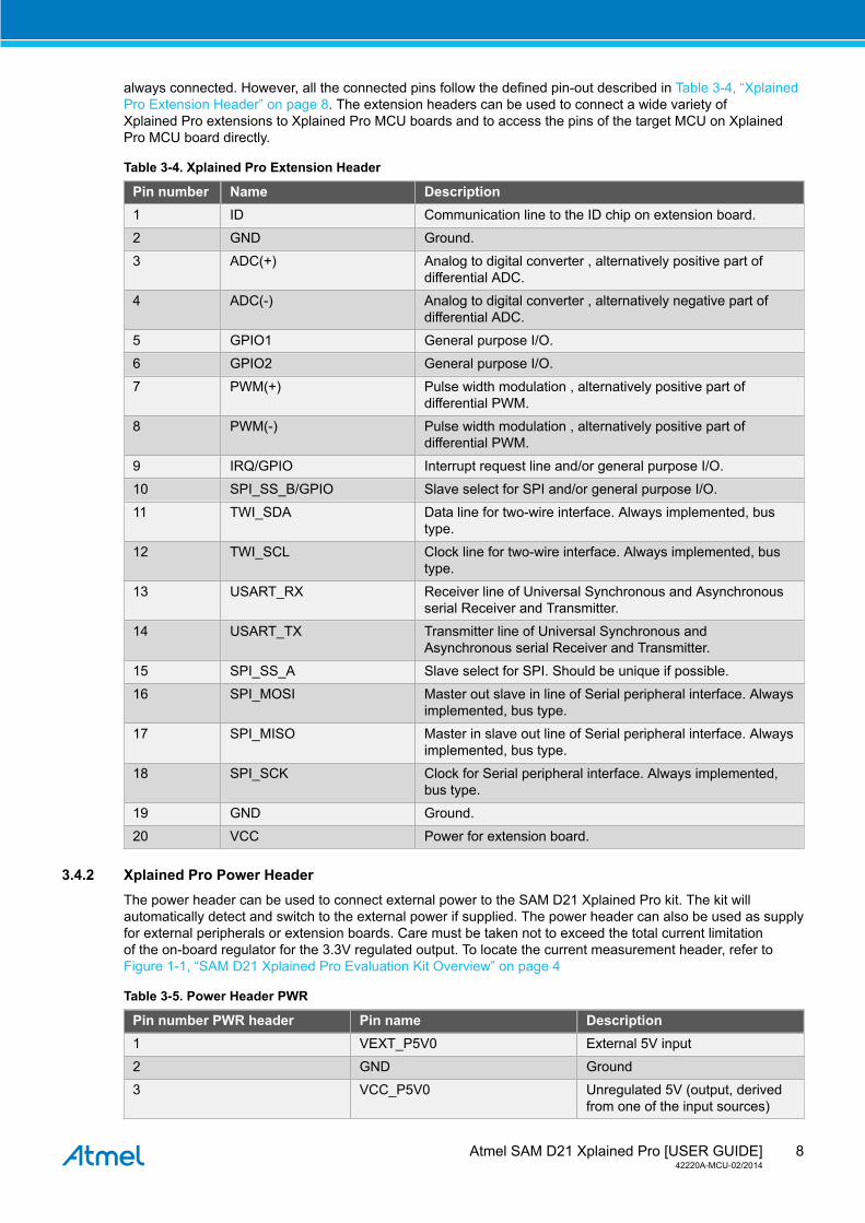
always connected. However, all the connected pins follow the defined pin-out described in Table 3-4, “XplainedPro Extension Header” on page 8. The extension headers can be used to connect a wide variety ofXplained Pro extensions to Xplained Pro MCU boards and to access the pins of the target MCU on XplainedPro MCU board directly.
Table 3-4. Xplained Pro Extension Header
Pin number Name Description1 ID Communication line to the ID chip on extension board.
2 GND Ground.
3 ADC(+) Analog to digital converter , alternatively positive part ofdifferential ADC.
4 ADC(-) Analog to digital converter , alternatively negative part ofdifferential ADC.
5 GPIO1 General purpose I/O.
6 GPIO2 General purpose I/O.
7 PWM(+) Pulse width modulation , alternatively positive part ofdifferential PWM.
8 PWM(-) Pulse width modulation , alternatively positive part ofdifferential PWM.
9 IRQ/GPIO Interrupt request line and/or general purpose I/O.
10 SPI_SS_B/GPIO Slave select for SPI and/or general purpose I/O.
11 TWI_SDA Data line for two-wire interface. Always implemented, bustype.
12 TWI_SCL Clock line for two-wire interface. Always implemented, bustype.
13 USART_RX Receiver line of Universal Synchronous and Asynchronousserial Receiver and Transmitter.
14 USART_TX Transmitter line of Universal Synchronous andAsynchronous serial Receiver and Transmitter.
15 SPI_SS_A Slave select for SPI. Should be unique if possible.
16 SPI_MOSI Master out slave in line of Serial peripheral interface. Alwaysimplemented, bus type.
17 SPI_MISO Master in slave out line of Serial peripheral interface. Alwaysimplemented, bus type.
18 SPI_SCK Clock for Serial peripheral interface. Always implemented,bus type.
19 GND Ground.
20 VCC Power for extension board.
3.4.2 Xplained Pro Power HeaderThe power header can be used to connect external power to the SAM D21 Xplained Pro kit. The kit willautomatically detect and switch to the external power if supplied. The power header can also be used as supplyfor external peripherals or extension boards. Care must be taken not to exceed the total current limitationof the on-board regulator for the 3.3V regulated output. To locate the current measurement header, refer toFigure 1-1, “SAM D21 Xplained Pro Evaluation Kit Overview” on page 4
Table 3-5. Power Header PWR
Pin number PWR header Pin name Description1 VEXT_P5V0 External 5V input
2 GND Ground
3 VCC_P5V0 Unregulated 5V (output, derivedfrom one of the input sources)
Atmel SAM D21 Xplained Pro [USER GUIDE]42220A-MCU-02/2014
9
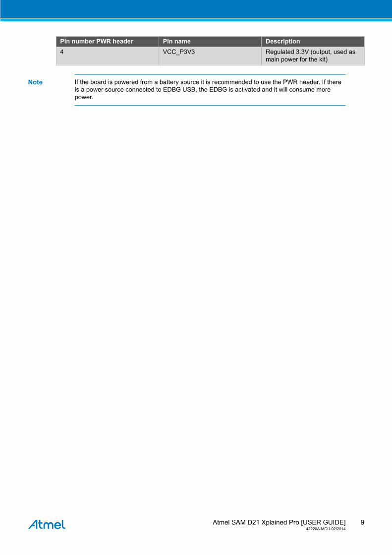
Pin number PWR header Pin name Description4 VCC_P3V3 Regulated 3.3V (output, used as
main power for the kit)
Note If the board is powered from a battery source it is recommended to use the PWR header. If thereis a power source connected to EDBG USB, the EDBG is activated and it will consume morepower.
Atmel SAM D21 Xplained Pro [USER GUIDE]42220A-MCU-02/2014
10
4. Hardware User Guide
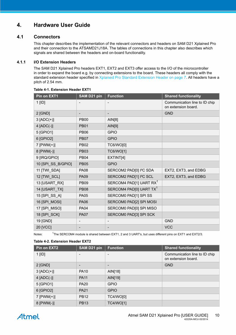
4.1 ConnectorsThis chapter describes the implementation of the relevant connectors and headers on SAM D21 Xplained Proand their connection to the ATSAMD21J18A. The tables of connections in this chapter also describes whichsignals are shared between the headers and on-board functionality.
4.1.1 I/O Extension HeadersThe SAM D21 Xplained Pro headers EXT1, EXT2 and EXT3 offer access to the I/O of the microcontrollerin order to expand the board e.g. by connecting extensions to the board. These headers all comply with thestandard extension header specified in Xplained Pro Standard Extension Header on page 7. All headers have apitch of 2.54 mm.
Table 4-1. Extension Header EXT1
Pin on EXT1 SAM D21 pin Function Shared functionality1 [ID] - - Communication line to ID chip
on extension board.
2 [GND] - - GND
3 [ADC(+)] PB00 AIN[8]
4 [ADC(-)] PB01 AIN[9]
5 [GPIO1] PB06 GPIO
6 [GPIO2] PB07 GPIO
7 [PWM(+)] PB02 TC6/WO[0]
8 [PWM(-)] PB03 TC6/WO[1]
9 [IRQ/GPIO] PB04 EXTINT[4]
10 [SPI_SS_B/GPIO] PB05 GPIO
11 [TWI_SDA] PA08 SERCOM2 PAD[0] I²C SDA EXT2, EXT3, and EDBG
12 [TWI_SCL] PA09 SERCOM2 PAD[1] I²C SCL EXT2, EXT3, and EDBG
13 [USART_RX] PB09 SERCOM4 PAD[1] UART RX1
14 [USART_TX] PB08 SERCOM4 PAD[0] UART TX1
15 [SPI_SS_A] PA05 SERCOM0 PAD[1] SPI SS
16 [SPI_MOSI] PA06 SERCOM0 PAD[2] SPI MOSI
17 [SPI_MISO] PA04 SERCOM0 PAD[0] SPI MISO
18 [SPI_SCK] PA07 SERCOM0 PAD[3] SPI SCK
19 [GND] - - GND
20 [VCC] - - VCC
Notes: 1The SERCOM4 module is shared between EXT1, 2 and 3 UART's, but uses different pins on EXT1 and EXT2/3.
Table 4-2. Extension Header EXT2
Pin on EXT2 SAM D21 pin Function Shared functionality1 [ID] - - Communication line to ID chip
on extension board.
2 [GND] - - GND
3 [ADC(+)] PA10 AIN[18]
4 [ADC(-)] PA11 AIN[19]
5 [GPIO1] PA20 GPIO
6 [GPIO2] PA21 GPIO
7 [PWM(+)] PB12 TC4/WO[0]
8 [PWM(-)] PB13 TC4/WO[1]
Atmel SAM D21 Xplained Pro [USER GUIDE]42220A-MCU-02/2014
11
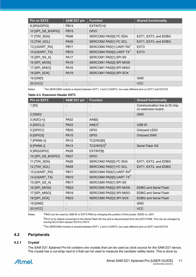
Pin on EXT2 SAM D21 pin Function Shared functionality9 [IRQ/GPIO] PB14 EXTINT[14]
10 [SPI_SS_B/GPIO] PB15 GPIO
11 [TWI_SDA] PA08 SERCOM2 PAD[0] I²C SDA EXT1, EXT3, and EDBG
12 [TWI_SCL] PA09 SERCOM2 PAD[1] I²C SCL EXT1, EXT3, and EDBG
13 [USART_RX] PB11 SERCOM4 PAD[1] UART RX1 EXT3
14 [USART_TX] PB10 SERCOM4 PAD[0] UART TX1 EXT3
15 [SPI_SS_A] PA17 SERCOM1 PAD[1] SPI SS
16 [SPI_MOSI] PA18 SERCOM1 PAD[2] SPI MOSI
17 [SPI_MISO] PA16 SERCOM1 PAD[0] SPI MISO
18 [SPI_SCK] PA19 SERCOM1 PAD[3] SPI SCK
19 [GND] - - GND
20 [VCC] - - VCC
Notes: 1The SERCOM4 module is shared between EXT1, 2 and 3 UART's, but uses different pins on EXT1 and EXT2/3.
Table 4-3. Extension Header EXT3
Pin on EXT3 SAM D21 pin Function Shared functionality1 [ID] - - Communication line to ID chip
on extension board.
2 [GND] - - GND
3 [ADC(+)] PA02 AIN[0]
4 [ADC(-)] PA03 AIN[1]1 USB ID
5 [GPIO1] PB30 GPIO Onboard LED0
6 [GPIO2] PA15 GPIO Onboard SW0
7 [PWM(+)] PA12 TC2/WO[0]
8 [PWM(-)] PA13 TC2/WO[1]2 Serial Flash SS
9 [IRQ/GPIO] PA28 EXTINT[8]
10 [SPI_SS_B/GPIO] PA27 GPIO
11 [TWI_SDA] PA08 SERCOM2 PAD[0] I²C SDA EXT1, EXT2, and EDBG
12 [TWI_SCL] PA09 SERCOM2 PAD[1] I²C SCL EXT1, EXT2, and EDBG
13 [USART_RX] PB11 SERCOM4 PAD[1] UART RX3
14 [USART_TX] PB10 SERCOM4 PAD[0] UART TX3
15 [SPI_SS_A] PB17 SERCOM5 PAD[1] SPI SS
16 [SPI_MOSI] PB22 SERCOM5 PAD[2] SPI MOSI EDBG and Serial Flash
17 [SPI_MISO] PB16 SERCOM5 PAD[0] SPI MISO EDBG and Serial Flash
18 [SPI_SCK] PB23 SERCOM5 PAD[3] SPI SCK EDBG and Serial Flash
19 [GND] - - GND
20 [VCC] - - VCC
Notes: 1PA03 can be used by USB ID or EXT3 PIN4 by changing the position of the jumper JS300 on J307.2PA13 is by default connected to the Serial Flash SS line and is disconnected from the EXT3 PIN8. This can be changed bymoving the 0-Ohm resistor R314 to R313.3The SERCOM4 module is shared between EXT1, 2 and 3 UART's, but uses different pins on EXT1 and EXT2/3.
4.2 Peripherals
4.2.1 CrystalThe SAM D21 Xplained Pro kit contains one crystals that can be used as clock source for the SAM D21 device.The crystal has a cut-strap next to it that can be used to measure the oscillator safety factor. This is done by
Atmel SAM D21 Xplained Pro [USER GUIDE]42220A-MCU-02/2014
12
cutting the strap and adding a resistor across the strap. More information about oscillator allowance and safetyfactor can be found in appnote AVR41001.
Table 4-4. External 32.768kHz Crystals
Pin on SAM D21 FunctionPA00 XIN32
PA01 XOUT32
4.2.2 Mechanical Buttons
SAM D21 Xplained Pro contains two mechanical buttons. One button is the RESET button connected to theSAM D21 reset line and the other is a generic user configurable button. When a button is pressed it will drivethe I/O line to GND.
Table 4-5. Mechanical Buttons
Pin on SAM D21 Silkscreen textRESETN RESET
PA15 SW0
4.2.3 LED
There is one yellow LED available on the SAM D21 Xplained Pro board that can be turned on and off. The LEDcan be activated by driving the connected I/O line to GND.
Table 4-6. LED Connections
Pin on SAM D21 LEDPB30 Yellow LED0
4.2.4 USB
The SAM D21 Xplained Pro has a micro USB receptable for use with the SAM D21 USB module. To be able todetect when a USB cable is connected, a GPIO is used to detect the VBUS voltage on the connector. The USBID line is used to detect if a host mode cable is connected and will automatically switch on the power to theUSB connector. The I/O connected to USB ID can be used to read the status of the line or manually overridethe voltage output. For other modes on the USB ID lines, refer to the USB organization specifications.
Table 4-7. USB Connections
Pin on SAM D21 USBPA14 VBUS Detection
PA03 USB ID
PA24 USB D-
PA25 USB D+
4.2.5 Serial Flash
The SAM D21 Xplained Pro has an onboard 8Mbit serial flash for non-voltatile storage of data.
Table 4-8. Serial Flash Connections
Pin on SAM D21 Function Serial Flash Shared functionalityPA13 GPIO #CS EXT3 PIN8 (default
disconnected)
PB22 SERCOM5 PAD[2] SPI MOSI SI EXT3 and EDBG
PB16 SERCOM5 PAD[0] SPI MISO SO EXT3 and EDBG
PB23 SERCOM5 PAD[3] SPI SCK SCK EXT3 and EDBG
1 http://www.atmel.com/images/doc8333.pdf
Atmel SAM D21 Xplained Pro [USER GUIDE]42220A-MCU-02/2014
13
4.3 Embedded Debugger ImplementationSAM D21 Xplained Pro contains an Embedded Debugger (EDBG) that can be used to program and debug theATSAMD21J18A using Serial Wire Debug (SWD). The Embedded Debugger also include a Virtual Com portinterface over UART, an Atmel Data Gateway Interface over SPI and TWI and it monitors four of the SAM D21GPIOs. Atmel Studio can be used as a front end for the Embedded Debugger.
4.3.1 Serial Wire DebugThe Serial Wire Debug (SWD) use two pins to communicate with the target. For further information on how touse the programming and debugging capabilities of the EDBG, see “Embedded Debugger” on page 6.
Table 4-9. SWD Connections
Pin on SAM D21 FunctionPA30 SWD clock
PA31 SWD data
4.3.2 Virtual COM PortThe Embedded Debugger acts as a Virtual Com Port gateway by using one of the ATSAMD21J18A UARTs.For further information on how to use the Virtual COM port see “Embedded Debugger” on page 6.
Table 4-10. Virtual COM Port Connections
Pin on SAM D21 FunctionPA22 SERCOM3 PAD[0] UART TXD (SAM D21 TX line)
PA23 SERCOM3 PAD[1] UART RXD (SAM D21 RX line)
4.3.3 Atmel Data Gateway InterfaceThe Embedded Debugger features an Atmel Data Gateway Interface (DGI) by using either a SPI or I²C port.The DGI can be used to send a variety of data from the SAM D21 to the host PC. For further information onhow to use the DGI interface see “Embedded Debugger” on page 6.
Table 4-11. DGI Interface Connections when using SPI
Pin on SAM D21 FunctionPB31 SERCOM5 PAD[1] SPI SS (Slave select) (SAM D21 is Master)
PB16 SERCOM5 PAD[0] SPI MISO (Master In, Slave Out)
PB22 SERCOM5 PAD[2] SPI MOSI (Master Out, Slave in)
PB23 SERCOM5 PAD[3] SPI SCK (Clock Out)
Table 4-12. DGI Interface Connections when using I²C
Pin on SAM D21 FunctionPA08 SERCOM2 PAD[0] SDA (Data line)
PA09 SERCOM2 PAD[1] SCL (Clock line)
Four GPIO lines are connected to the Embedded Debugger. The EDBG can monitor these lines and timestamp pin value changes. This makes it possible to accurately time stamp events in the SAM D21 applicationcode. For further information on how to configure and use the GPIO monitoring features see “EmbeddedDebugger” on page 6.
Table 4-13. GPIO Lines Connected to the EDBG
Pin on SAM D21 FunctionPA27 GPIO0
PA28 GPIO1
PA20 GPIO2
PA21 GPIO3
Atmel SAM D21 Xplained Pro [USER GUIDE]42220A-MCU-02/2014
14
5. Hardware Revision History and Known Issues
5.1 Identifying Product ID and RevisionThe revision and product identifier of Xplained Pro boards can be found in two ways, through Atmel Studio orby looking at the sticker on the bottom side of the PCB.By connecting a Xplained Pro MCU board to a computer with Atmel Studio running, an information window willpop up. The first six digits of the serial number, which is listed under kit details, contain the product identifierand revision. Information about connected Xplained Pro extension boards will also appear in the Atmel Kitswindow.The same information can be found on the sticker on the bottom side of the PCB. Most kits will print theidentifier and revision in plain text as A09-nnnn\rr where nnnn is the identifier and rr is the revision. Boards withlimited space have a sticker with only a QR-code which contains a serial number string.The serial number string has the following format:
"nnnnrrssssssssss" n = product identifier r = revision s = serial number
The kit identifier for SAM D21 Xplained Pro is 2130.
5.2 Revision 2Revision 2 of SAM D21 Xplained Pro is the initial released version.
Atmel SAM D21 Xplained Pro [USER GUIDE]42220A-MCU-02/2014
15
6. Document Revision History
Documentrevision
Date Comment
42220A 02/2014 Initial document release
Atmel SAM D21 Xplained Pro [USER GUIDE]42220A-MCU-02/2014
16
7. Evaluation Board/Kit Important Notice
This evaluation board/kit is intended for use for FURTHER ENGINEERING, DEVELOPMENT,DEMONSTRATION, OR EVALUATION PURPOSES ONLY. It is not a finished product and may not (yet)comply with some or any technical or legal requirements that are applicable to finished products, including,without limitation, directives regarding electromagnetic compatibility, recycling (WEEE), FCC, CE or UL(except as may be otherwise noted on the board/kit). Atmel supplied this board/kit "AS IS," without anywarranties, with all faults, at the buyer's and further users' sole risk. The user assumes all responsibilityand liability for proper and safe handling of the goods. Further, the user indemnifies Atmel from all claimsarising from the handling or use of the goods. Due to the open construction of the product, it is the user'sresponsibility to take any and all appropriate precautions with regard to electrostatic discharge and any othertechnical or legal concerns.EXCEPT TO THE EXTENT OF THE INDEMNITY SET FORTH ABOVE, NEITHER USER NORATMEL SHALL BE LIABLE TO EACH OTHER FOR ANY INDIRECT, SPECIAL, INCIDENTAL, ORCONSEQUENTIAL DAMAGES.No license is granted under any patent right or other intellectual property right of Atmel covering or relatingto any machine, process, or combination in which such Atmel products or services might be or are used.

Atmel Corporation 1600 Technology Drive, San Jose, CA 95110 USA T: (+1)(408) 441.0311 F: (+1)(408) 436.4200 | www.atmel.com
© 2014 Atmel Corporation. All rights reserved. / Rev.: 42220A-MCU-02/2014
Atmel®, Atmel logo and combinations thereof, Enabling Unlimited Possibilities®, AVR®, and others are registered trademarks or trademarks of AtmelCorporation or its subsidiaries. Windows® is a registered trademark of Microsoft Corporation in U.S. and or other countries. ARM®, Cortex® and others isa registered trademark of ARM Ltd. Other terms and product names may be trademarks of others.
Disclaimer: The information in this document is provided in connection with Atmel products. No license, express or implied, by estoppel or otherwise, to any intellectual property right is grantedby this document or in connection with the sale of Atmel products. EXCEPT AS SET FORTH IN THE ATMEL TERMS AND CONDITIONS OF SALES LOCATED ON THE ATMEL WEBSITE,ATMEL ASSUMES NO LIABILITY WHATSOEVER AND DISCLAIMS ANY EXPRESS, IMPLIED OR STATUTORY WARRANTY RELATING TO ITS PRODUCTS INCLUDING, BUT NOTLIMITED TO, THE IMPLIED WARRANTY OF MERCHANTABILITY, FITNESS FOR A PARTICULAR PURPOSE, OR NON-INFRINGEMENT. IN NO EVENT SHALL ATMEL BE LIABLE FORANY DIRECT, INDIRECT, CONSEQUENTIAL, PUNITIVE, SPECIAL OR INCIDENTAL DAMAGES (INCLUDING, WITHOUT LIMITATION, DAMAGES FOR LOSS AND PROFITS, BUSINESSINTERRUPTION, OR LOSS OF INFORMATION) ARISING OUT OF THE USE OR INABILITY TO USE THIS DOCUMENT, EVEN IF ATMEL HAS BEEN ADVISED OF THE POSSIBILITY OFSUCH DAMAGES. Atmel makes no representations or warranties with respect to the accuracy or completeness of the contents of this document and reserves the right to make changes tospecifications and products descriptions at any time without notice. Atmel does not make any commitment to update the information contained herein. Unless specifically provided otherwise,Atmel products are not suitable for, and shall not be used in, automotive applications. Atmel products are not intended, authorized, or warranted for use as components in applications intendedto support or sustain life.


![Atmel AT01639: XMEGA-C3 Xplained Software …ww1.microchip.com/downloads/en/AppNotes/Atmel-42090...Atmel AT01639: XMEGA-C3 Xplained Software User Guide [APPLICATION NOTE] 42090A−AVR−02/2013](https://img.pdfslide.net/doc/110x75/5ee0c5daad6a402d666be2b6/atmel-at01639-xmega-c3-xplained-software-ww1-atmel-at01639-xmega-c3-xplained.jpg)


![Atmel | SMART SAMA5D3 Series - Microchip Technologyww1.microchip.com/downloads/en/DeviceDoc/Atmel-11269-32...SAMA5D3 Xplained [USER GUIDE] Atmel-11269D-ATARM-SAMA5D3-Xplained-XPLD-User](https://img.pdfslide.net/doc/110x75/5aedd4107f8b9a3669917d67/atmel-smart-sama5d3-series-microchip-xplained-user-guide-atmel-11269d-atarm-sama5d3-xplained-xpld-user.jpg)

![Atmel AT02657: XMEGA-E5 Xplained Software User Guideww1.microchip.com/downloads/en/AppNotes/Atmel... · Atmel AT02657: XMEGA-E5 Xplained Software User Guide [APPLICATION NOTE] 42085A−AVR−04/2013](https://img.pdfslide.net/doc/110x75/5f88ba81f6b36722b04d705d/atmel-at02657-xmega-e5-xplained-software-user-atmel-at02657-xmega-e5-xplained.jpg)

![Atmel AT06475: SAM D21 USB - Microchip Technologyww1.microchip.com/downloads/.../Atmel-42261-SAM-D21... · AT06475: SAM D21 USB [APPLICATION NOTE] 42261A−ARM−03/2014 4 Figure](https://img.pdfslide.net/doc/110x75/5eb8bb248958705a235105a3/atmel-at06475-sam-d21-usb-microchip-at06475-sam-d21-usb-application-note-42261aaarma032014.jpg)