Embed Size (px)
Citation preview

Journal of Microscopy, Vol. 226, Pt 3 June 2007, pp. 207–217
Received 20 July 2006; accepted 13 February 2007
Atomic force microscope (AFM) combined with theultramicrotome: a novel device for the serial section tomographyand AFM/TEM complementary structural analysis of biologicaland polymer samples
A N T O N E . E F I M OV∗, A L E X A N D E R G : T O N E V I T S K Y†,M A R I A D I T T R I C H‡ & NA D E Z DA B . M AT S KO §∗NT-MDT Co., Moscow, Russia
†Scientific Research Institute of Transplantology and Artificial Organs, Moscow, Russia
‡Swiss Federal Institute of Aquatic Science and Technology (EAWAG), Kastanienbaum, Switzerland
§Electron Microscopy Centre Zurich (EMEZ), ETH-Zurich, Switzerland
Keywords. AFM, cells, microtomy, polymers, TEM, 3D serial sectiontomography.
Summary
A new device (NTEGRA Tomo) that is based on the integrationof the scanning probe microscope (SPM) (NT-MDT NTEGRASPM) and the Ultramicrotome (Leica UC6NT) is presented.This integration enables the direct monitoring of a blockface surface immediately following each sectioning cycleof ultramicrotome sectioning procedure. Consequently, thisdevice can be applied for a serial section tomography of the widerange of biological and polymer materials. The automation ofthe sectioning/scanning cycle allows one to acquire up to 10consecutive sectioned layer images per hour. It also permits tobuild a 3-D nanotomography image reconstructed from severaltens of layer images within one measurement session. Thethickness of the layers can be varied from 20 to 2000 nm, andcan be controlled directly by its interference colour in water.
Additionally, the NTEGRA Tomo with its nanometerresolution is a valid instrument narrowing and highlightingan area of special interest within volume of the sample. Forembedded biological objects the ultimate resolution of SPMmostly depends on the quality of macromolecular preservationof the biomaterial during sample preparation procedure. Formost polymer materials it is comparable to transmissionelectron microscopy (TEM).
Correspondence to: Dr. Nadezda B. Matsko, Forschungsinsstitut fur
Elektronenmikroskopie, und Feinstrukturforschung (FELMI-ZFE), Steyrergasse
17, A-8010 Graz, Austria. Tel: +43 (0)316 8738335; fax: +43 (0)316 811596;
e-mail: [email protected]
The NTEGRA Tomo can routinely collect complementary AFMand TEM images. The block face of biological or polymersample is investigated by AFM, whereas the last ultrathinsection is analyzed with TEM after a staining procedure. Usingthe combination of both of these ultrastructural methodsfor the analysis of the same particular organelle or polymerconstituent leads to a breakthrough in AFM/TEM imageinterpretation. Finally, new complementary aspects of theobject’s ultrastructure can be revealed.
1. Introduction
The ability of modern high-resolution electron microscopesto produce images at near atomic resolution has led totremendous progress in many fields of biological and materialresearch. However, the vast majority of images are 2Dprojections of a 3D structure. Nowadays the third dimensionbecomes increasingly important for the comprehensiveunderstanding of the object’s ultrastructure (Midgley &Weyland, 2003). In addition, for many applications in biologyand polymer science 3D analysis has to be performed within alayer of up to several hundred micrometers thick.
At present 3D structure can be reconstructed with theresolution in the nanometers range using either tilt-series-based or serial ultrathin sections tomography. A tilt-series-based tomography can be obtained with transmission electronmicroscopy (TEM) (Horowitz et al., 1997; Medalia et al., 1997;Perkins et al., 1997), transmission X-ray microscopy (TXM)(Kaestner et al., 2003; Sutton et al., 2003), energy-filteredTEM (EFTEM) (Midgley & Weyland, 2003), atom probe field ion
C© 2007 The AuthorsJournal compilation C© 2007 The Royal Microscopical Society

2 0 8 A . E . E F I M OV E T A L .
microscopy (APFIM) (Miller, 2000) and high-angle annular-dark field scanning transmission electron microscopy (HAADFSTEM) (Koguchi et al., 2001).
Serial ultrathin sections tomography is based on 3DTEM (Howard & Eins, 1984) or AFM (Chen et al., 2005)reconstruction of serial ultrathin sections or, alternatively,block-face imaging combined with serial sectioning inside thechamber of a scanning electron microscope (SEM) (Denk &Horstmann, 2004; Heymann et al., 2006). The sectioningprocedure can be also performed using focused ion beams (FIBtomography) (Holzer et al., 2004).
However, these currently available methods have drawbacksthat limit their applications. Thin samples in the 100-nmrange are necessary for a tilt-series-based tomography. Thisrequirement complicates the application of these methodsfor reconstruction of larger volume structures. Furthermore,the necessity to use only electron- and photon-transparentmaterials strictly limits the number (types) of specimens, whichare acceptable for such analysis.
Serial ultrathin sections tomography is suitable for thereconstruction of the large specimens. However, this methodfaces two severe problems. First, serial sections preparationhere is very time-consuming. Second is a low electronmicroscopy contrast of biological and polymer materialsbecause the light elements they consist of scatter the incidentelectrons rather weakly. The first problem may be solved bycomplete automation of the microtomy (Denk & Horstmann,2004). Applying high voltages, and staining may enhancethe weak scattering. However, high voltages usually leadto the beam damage of the samples. Staining of the wholesample can considerably improve the contrast, but the heavymetal salts, which are used for such purpose have a finitesize and can penetrate deep into the sample only when thecellular macromolecule matrix are partially or completelyremoved. Therefore only those fixation methods, which areaggressive to macromolecules like classical chemical fixationfollowed by rapid dehydration, can provide a sufficient blockstaining of biological samples (Hunziker et al., 1984; Hayat,2000). For polymer samples staining with different chemicals(e.g. OsO4, RuO4) is normally used. However, this procedurecan change the native structure of the phases (Sawyer &Grubb, 1996). Therefore, the block staining for EM is oneof the most serious limitations for the gentle fixation ofthe biological tissue/polymer composites, and, thus, for theirproper structural preservation.
By contrast, the analysis of the block face of polymermaterials with AFM does not require the staining of thespecimen. The reason for this is the different principle of animage contrast formation in EM and AFM. In EM an imagecontrast is formed by the sufficiently scattering structuresfrom 15- to 90-nm-thick volume of a section (TEM analysis)or 10–100 nm surface layer of block (SEM analysis atlow energies) (Reimer, 1993). As a result, only the cellconstituents, which react with the staining agents, and which
can be reached by the latter, are detected. Where as, imagecontrast in the AFM is due to a height corrugation or aphase shift generated by surface inhomogeneities (Matsko &Mueller, 2004). Such inhomogenities appear on the surfaceof the block face due to copolymerized cell components(mainly macromolecules) (Matsko, 2006). All of them canbe observed without staining on the plane of the section,and not in the 2D projection, like with TEM. Consequently,the correlative AFM/TEM structural analysis provides newultrastructural aspects of a macromolecular arrangement of abiosamples.
In this article we describe a new instrument (NTEGRATomo),whichisbasedontheintegrationofNT-MDT’sNTEGRASPM platform and the Leica UC6NT ultramicrotome. Our goalwas to develop the device, which enables the direct monitoringof the block face structure of the specimen while it is withinthe cycle of the ultramicrotome sectioning procedure. Thiscombinationof instrumentshasanadvantageinthefastsearchof an area of special interest of the sample by scanning theblock face each time a layer was removed by the microtomeknife. The efficiency of this area detection for biologicalspecimens depends on the quality of their macromolecularpreservation during sample preparation procedure. For mostpolymer materials it is comparable with TEM.
Three-dimensional reconstruction in the NTEGRA Tomocan be obtained by automated block-face imaging combinedwith serial sectioning by the ultramicrotome. The step sizecan be varied from 20 to 2000 nm according to themicrotome adjustments, and can be controlled directly by itsinterference colour in the water. Automation and optimizationof sectioning/scanning cycle allow one to acquire up to10 consequent layer images per hour and to perform thenanotomography from several tens of layer images within onemeasuring session.
With this new instrument (the NTEGRA Tomo) TEM andAFM complementary pairs of images can be routinely preparedand analyzed. The block face of the biological or polymersample was prepared for AFM while the last ultrathin sectionwas collected, post-stained and used for TEM. Finally thesame ultrastructure will be investigated by two complementarymethods, allowing for correspondence of stained structure andtheir macromolecular/phase composition.
2. Materials and methods
2.1. High- pressure freezing
Adult C. elegans, kind gifts of Prof. M. Gotti, ETH Zurich,and cyanobacteria Synechococcus PCC 7942, from chemostatecultures grown in Z/10 medium were washed (Dittrich andSibler, 2005; Obst et al., 2006) and high-pressure frozen asdescribed earlier (Hohenberg et al., 1994)
Life cat’s mite Otodectes cynotis was mounted in aluminiumplatelets filled with hexadecane and immediately frozen.
C© 2007 The AuthorsJournal compilation C© 2007 The Royal Microscopical Society, Journal of Microscopy, 226, 207–217

A F M C O M B I N E D W I T H T H E U LT R A M I C RO T O M E 2 0 9
All freezing procedures were performed by a HPM 010 high-pressure freezer (Bal-Tec, Principality of Liechtenstein).
2.2. Freeze-substitution and embedding
Epoxy freeze-substitution was performed in water-free acetonecontaining 15% of the complete Araldite/Epon formulation[49% w/w Araldite/Epon stock solution, 49% w/w HardenerDDSA (Fluka) and 2% w/w Accelerator DMP-30 (Fluka). TheAraldite/Epon stock solution consisted of 41% w/w Epoxy-Einbettungsmittel (Fluka), 54% w/w Durcupan ACM (Fluka)and 5% w/w Dibutylphthalate (Fluka)].
The standard freeze-substitution regime, where the sampleswere kept at −90◦C, −60◦C and −30◦C for 8 h at eachtemperature, and finally warmed to 0◦C, was used (VanHarreveld & Crowell, 1964). Between the steps, thetemperature was raised by 1◦C/min.
All samples were embedded in Araldite/Epon embeddingmixture. Infiltration was performed stepwise (33% resin inwater-free acetone for 4 h, 66% resin in acetone for 4 h, 100%resin overnight in a desiccator evacuated with a membranepump to 10 mbar to maintain dry conditions). All sampleswere polymerized at 60◦C for 3 days.
2.3. Transmission electron microscopy
Ultrathin sections (10–50 nm) were obtained using a LeicaUltracutEmicrotome(Leica,Austria)equippedwithadiamondknife (Diatome, Switzerland). Sections for TEM analysis werecollected on kollodium/carbon coated grids, stained withuranyl acetate and lead citrate (Reynolds, 1963) and examinedin a EM 912 Omega (Zeiss, Oberkochen BRD) electronmicroscope equipped with a ProScan 1 k × 1 k slow scan CCDcamera (Proscan, Munich, BRD).
3. Results and discussion
3.1. AFM head – principle and construction
To achieve the goals outlined in the Introduction, a specialAFM head was designed. This AFM head is placed directly onthe ultramicrotome (Leica UC6NT series) knife holder over theknife. This construction allows the investigation of the blockface surface when the ultramicrotome arm is in the highestposition. The principle of combined AFM and UMT operationis shown on Fig. 1.
The cantilever tip scans the block face surface using ahorizontally oriented piezotube scanner with the scanningrange of 100 × 100 × 10 µm. The scanner is equipped withcapacitance displacement sensors for all three coordinates andhas the closed-loop control of probe positioning in the scanningplane. To detect the probe displacement we use standard opticalcantilever deflection registration system, which consists of asemiconductor laser and a four-section photodiode.
The major components of the instrument are illustrated inFig. 2. AFM head with three support legs is clamped with spring
Fig. 1. Schematic illustration of a combination of AFM measuring system,with sectioning part of the microtome. 1 – sample; 2 – sample holder; 3– ultramicrotome arm; 4 – ultramicrotome knife; 5 – AFM scanner; 6 –holder for AFM probe and and 7 – AFM probe.
Fig. 2. NTEGRA Tomo AFM head in measuring (A) and sectioning (B)positions. 1 – AFM probe; 2 – sample; 3 – ultramicrotome knife; 4 – springlocks; 5 – support platform; 6 – stepper motor for probe approach; 7 –positioning microscrews; 8 – polysapphire plate; 9 – support pivots; 10 –motorized rear screw and 11 – ultramicrotome arm support.
C© 2007 The AuthorsJournal compilation C© 2007 The Royal Microscopical Society, Journal of Microscopy, 226, 207–217
2 1 0 A . E . E F I M OV E T A L .
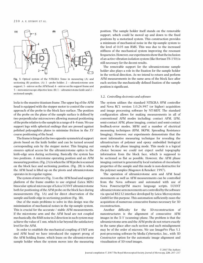
Fig. 3. Optical system of the NTEGRA Tomo in measuring (A) andsectioning (B) position. (A) 1 –probe holder; 2 – ultramicrotome armsupport; 3 – mirror on the AFM head; 4 – mirror on the support frame and5 – stereomicroscope objective lens; (B) 1 – ultramicrotome knife and 2 –sectioned sample.
locks to the massive titanium frame. The upper leg of the AFMhead is equipped with the stepper motor to control the coarseapproach of the probe to the block face surface. The positionof the probe on the plane of the sample surface is defined bytwo perpendicular microscrews allowing manual positioningof the probe relative to the sample in a range of 4–8 mm. We usesupport legs with spherical endings that are pressed againstpolished polysapphire plates to minimize friction in the XYcoarse positioning of the head.
The frame is hinged at the two opposite symmetrical supportpivots based on the knife holder and can be turned aroundcorresponding axis by the stepper motor. This hinging outensures optical access for the ultramicrotome optics to theknife-edge area during sectioning. Basically the system hastwo positions. A microtome operating position and an AFMmeasuringposition.(Fig.2A)iswhentheAFMprobeisscannedon the block face and sectioning position. (Fig. 2B) is whenthe AFM head is lifted up on the pivots and ultramicrotomeoperates in its regular regime.
The system of mirrors (Fig. 3) on the AFM head and supportplatform of the frame enables to use original (Leica MZ6)binocular optical microscope of Leica UC6NT ultramicrotomeboth for positioning of the AFM probe on the block face duringmeasurements (Fig. 3A) and for direct observation of thesample and knife edge in sectioning position (Fig. 3B).
One of the main problems to solve in this design was theminimization of mechanical noises in the tip-sample system.This is crucial for the accurate / stable AFM measurements.If the microtome arm and the AFM head are not coupledmechanically, the RMS noise in Z direction in such system mayachieve the value of 1 nm, which is far beyond the satisfactorylevel for the AFM.
In order to establish the mechanical coupling of UMT armand AFM head we have introduced the support prong ofthe AFM holding frame, which leans on the ultramicrotomesample holder when the system moves into the measuring
position. The sample holder itself stands on the removablesupport, which could be moved up and down to the fixedpositions by a motorized system. This construction providesa minimum of mechanical noise in the tip-sample system tothe level of 0.05 nm RMS. This was due to the increasedstiffness of the mechanical system improving the resonantfrequencies. However, our experiments show that the inclusionof an active vibration isolation system (like Hertzan TS-150) isstill necessary for the decent results.
The removable support for the ultramicrotome sampleholder also plays a role in the fixation for the sample holderin the vertical direction. As we intend to return and performAFM measurements in the same area of the block face aftereach section the mechanically defined fixation of the sampleposition is significant.
3.2. Controlling electronics and software
The system utilizes the standard NTEGRA SPM controllerand Nova RC1 version 1.0.26.997 (or higher) acquisitionand image processing software by NT-MDT. The standardconfiguration allows for making measurements in all ofconventional AFM modes including: contact AFM, LFM,semi-contact AFM, phase imaging, contact and semi-contactfeedback-error modes, MFM and a number of electricalmeasuring techniques (EFM, SKPM, Spreading ResistanceImaging). However, our experiments demonstrate that themost informative measuring technique for revealing theultrastructure of polymer and epoxy embedded biologicalsamples is the phase imaging mode. This mode is a logicalchoice because we could not expect useful topographyinformation from the block face, which is supposed tobe sectioned as flat as possible. However, the AFM phaseimaging contrast is generated by local variation of viscoelasticproperties of the sample and this mode is non-destructive forthe polymer samples (Magonov & Reneker: 1997).
The operation of ultramicrotome arm and AFM headmovements as well as AFM measurements can be controlledfrom the Nova software and automated with use ofNova PowerscriptTM macro language scripts. UC6NTultramicrotome arm movements are controlled by the softwarevia special RS232 interface developed by Leica MicrosystemsGmbH for this purpose. This automation sufficiently eases theacquisition of numerous consecutive frames necessary for 3Dreconstruction.
Another difficulty for the 3D-reconstruction ofnanostructures is the alignment of consecutive AFMimages in the X-Y (scanning) plane. The problem is that theultramicrotome arm and the AFM probe do not return exactlyin the same place after each section and such misalignmentmay be of the order of microns. We use ImagePro Plus 5.1post-processing software by Media Cybernetics, Inc., with 3DConstructor option for the automatic image alignment andvisualization of 3D voxel images.
C© 2007 The AuthorsJournal compilation C© 2007 The Royal Microscopical Society, Journal of Microscopy, 226, 207–217
A F M C O M B I N E D W I T H T H E U LT R A M I C RO T O M E 2 1 1
3.3. Identification of specified area of interest within the sample
The investigation of the ultrastructural aspects of the biologicalobjects often requires finding an area of interest for TEManalysiswithinalargevolumeorareaofthesample.Sometimesthe searching procedure becomes extremely complicated,especially when the goal is to detect the tinniest cellulardetails like local networks of neurons or rarely distributedphases/defects within polymer composites. The thing thatcontributes to this effect is a disability to make a primaryscreening of the area of a sample, which is currently under thesectioning,withtheresolutioncomparabletoTEM.Tillnowtherough screening is performed through light microscope (LM)(semi-thin sections) (Roessler et al., 1991; Schwarz, 1994)or confocal laser scanning microscope (CLSM) (block face)(Biel et al., 2003). For the latter a fluorescent dye should beincluded in early steps of a sample preparation procedure. Suchtechniques allow one to detect structural details not smallerthan a several hundreds of nanometers, and cannot be usedfor the observation of most of cellular constituents, bacteriaetc. For polymers such methods cannot be used at all due toabsence of the intense fluorescent labelling within a samplevolume.
Therefore, a more sophisticated approach to find the areaof interest is based on usual ultrathin section preparationfollowing to TEM examination. However, such proceduresometimes takes weeks of a hard work and newer gives theguarantee of success.
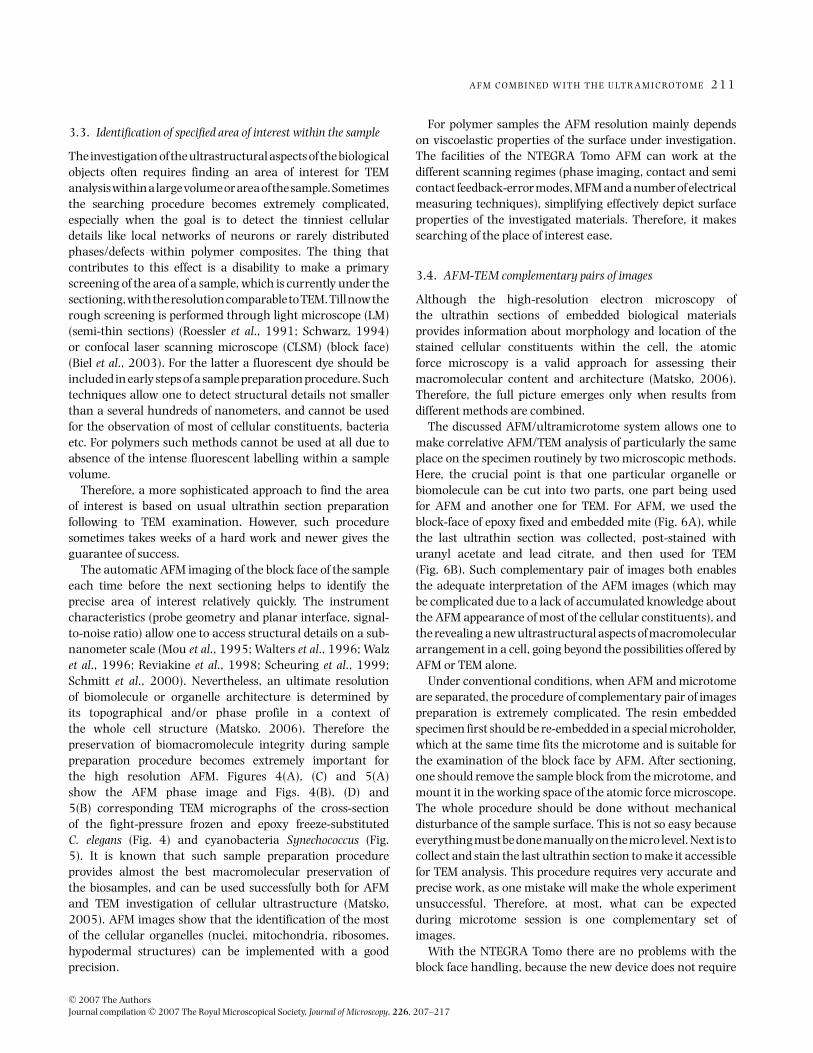
The automatic AFM imaging of the block face of the sampleeach time before the next sectioning helps to identify theprecise area of interest relatively quickly. The instrumentcharacteristics (probe geometry and planar interface, signal-to-noise ratio) allow one to access structural details on a sub-nanometer scale (Mou et al., 1995; Walters et al., 1996; Walzet al., 1996; Reviakine et al., 1998; Scheuring et al., 1999;Schmitt et al., 2000). Nevertheless, an ultimate resolutionof biomolecule or organelle architecture is determined byits topographical and/or phase profile in a context ofthe whole cell structure (Matsko, 2006). Therefore thepreservation of biomacromolecule integrity during samplepreparation procedure becomes extremely important forthe high resolution AFM. Figures 4(A), (C) and 5(A)show the AFM phase image and Figs. 4(B), (D) and5(B) corresponding TEM micrographs of the cross-sectionof the fight-pressure frozen and epoxy freeze-substitutedC. elegans (Fig. 4) and cyanobacteria Synechococcus (Fig.5). It is known that such sample preparation procedureprovides almost the best macromolecular preservation ofthe biosamples, and can be used successfully both for AFMand TEM investigation of cellular ultrastructure (Matsko,2005). AFM images show that the identification of the mostof the cellular organelles (nuclei, mitochondria, ribosomes,hypodermal structures) can be implemented with a goodprecision.
For polymer samples the AFM resolution mainly dependson viscoelastic properties of the surface under investigation.The facilities of the NTEGRA Tomo AFM can work at thedifferent scanning regimes (phase imaging, contact and semicontact feedback-error modes, MFM and a number of electricalmeasuring techniques), simplifying effectively depict surfaceproperties of the investigated materials. Therefore, it makessearching of the place of interest ease.
3.4. AFM-TEM complementary pairs of images
Although the high-resolution electron microscopy ofthe ultrathin sections of embedded biological materialsprovides information about morphology and location of thestained cellular constituents within the cell, the atomicforce microscopy is a valid approach for assessing theirmacromolecular content and architecture (Matsko, 2006).Therefore, the full picture emerges only when results fromdifferent methods are combined.
The discussed AFM/ultramicrotome system allows one tomake correlative AFM/TEM analysis of particularly the sameplace on the specimen routinely by two microscopic methods.Here, the crucial point is that one particular organelle orbiomolecule can be cut into two parts, one part being usedfor AFM and another one for TEM. For AFM, we used theblock-face of epoxy fixed and embedded mite (Fig. 6A), whilethe last ultrathin section was collected, post-stained withuranyl acetate and lead citrate, and then used for TEM(Fig. 6B). Such complementary pair of images both enablesthe adequate interpretation of the AFM images (which maybe complicated due to a lack of accumulated knowledge aboutthe AFM appearance of most of the cellular constituents), andthe revealing a new ultrastructural aspects of macromoleculararrangement in a cell, going beyond the possibilities offered byAFM or TEM alone.
Under conventional conditions, when AFM and microtomeare separated, the procedure of complementary pair of imagespreparation is extremely complicated. The resin embeddedspecimen first should be re-embedded in a special microholder,which at the same time fits the microtome and is suitable forthe examination of the block face by AFM. After sectioning,one should remove the sample block from the microtome, andmount it in the working space of the atomic force microscope.The whole procedure should be done without mechanicaldisturbance of the sample surface. This is not so easy becauseeverything must be done manually on the micro level. Next is tocollect and stain the last ultrathin section to make it accessiblefor TEM analysis. This procedure requires very accurate andprecise work, as one mistake will make the whole experimentunsuccessful. Therefore, at most, what can be expectedduring microtome session is one complementary set ofimages.
With the NTEGRA Tomo there are no problems with theblock face handling, because the new device does not require
C© 2007 The AuthorsJournal compilation C© 2007 The Royal Microscopical Society, Journal of Microscopy, 226, 207–217
2 1 2 A . E . E F I M OV E T A L .
Fig. 4. Corresponding (A, C) AFM phase (block face) and (B, D) TEM (ultrathin section) images of the cross section of the adult C. elegans which are high-pressure frozen and freeze-substituted in acetone containing 20% Epon/Araldite mixture. Black arrows point to mitochondrial and nucleus membranes.Phase variation: 0◦–15◦ in (A, C). Scale bars equal 500 nm in (A, B), and 200 nm in (C, D). N nucleus, m mitochondria, bm body-wall muscles, ERendoplasmic reticulum, cm cell membrane.
a special holder for AFM examination, and after sectioningthe procedure of AFM approaching the block face surface isdone automatically. The ultrathin section preparation remainsalmost the same. However, the efficiency of the complementaryset of image preparation is greatly increased due to the
increased ability to produce several AFM images of the blockface during one microtome session (consequent AFM scanning– section preparation). At the end of microtome session onecan have several ultrathin sections, which have been alreadyanalyzed by the AFM, and a few of them can be well situated on
C© 2007 The AuthorsJournal compilation C© 2007 The Royal Microscopical Society, Journal of Microscopy, 226, 207–217

A F M C O M B I N E D W I T H T H E U LT R A M I C RO T O M E 2 1 3
Fig. 5. Corresponding (A) AFM phase (block face) and (B) TEM (ultrathin section) images of cyanobacterias Synechococcus which are high-pressure frozenand freeze-substituted in acetone containing 20% Epon/Araldite mixture. Phase variation: 0◦–20◦ in (A). Scale bars equal 500 nm. TH thylakoid, Ppolyphosphate granule.
Fig. 6. AFM phase (A)/TEM (B) complementary pairs of images of a longitudinal section of cat‘s mite Otodectes cynotis, high-pressure frozen and freeze-substituted in acetone containing 20% Epon/Araldite mixture. Phase variation: 0◦–4◦ in (A). Scale bars equal 500 nm. N nucleus, m mitochondria, cmcell membrane, ch chitin.
C© 2007 The AuthorsJournal compilation C© 2007 The Royal Microscopical Society, Journal of Microscopy, 226, 207–217

2 1 4 A . E . E F I M OV E T A L .
the grid and properly stained to allow them to be successfullyexamined by TEM.
3.5. 3D image reconstruction and control of section thickness
AFM 3D structural analysis (analogous to the serial sectioningTEM reconstruction) implies that the sections are imagedbefore being cut, i.e. by repeatedly scanning the block face. Twoimportant technical requirements for this technique should bementioned.
First is the alignment of the images with regard to theirdisplacement in the scanning plane. The x-y displacement ofthe probe-sample relative position is generated by a numberof factors including: mechanical repeatability of the systempositioning, thermal and other drifts and block face relaxationafter sectioning. The total mismatch of the images from frameto frame may reach several microns. We utilize ImagePro Plus5.1 3D Constructor software for automatic image alignmentby a correlation-based algorithm. For 3D reconstruction ona smaller scale when the scan size is comparable to typicalmismatch values we were first acquiring the larger areaoverview image in order to locate the feature of interest andthen zooming in on the smaller area. As the AFM scanner ofNTEGRA Tomo is equipped with closed loop control based oncapacitance sensors the measurement does not introduce anysignificant additional error.
The second important requirement is the control ofsection thickness. This is still a limiting factor for high-resolution 3D imaging via ultramicrotomy. After sectioningAFMmeasurementsstill take5–10minand,therefore, thermaldrift and block face relaxation can lead to errors comparablewith the thickness of ultrathin (10–50 nm) section. Howeverthere is a well-established technique for section thicknesscontrol based on optical detection of the interference colourin light reflected from the section while it is floating onthe surface of a liquid in the knife trough (Hayat, 2000).Moreover this technique is the only one, which enables one todirectly measure the thickness of the section during sectioningprocedure with accuracy of a 10-nm range. The AFM headconstruction allows one the optical access to the knife-edgearea during sectioning, thus colours of the sections may beobserved in the regular way. To systematize section colour datavideo images from the optical microscope after each sectioncan be acquired and stored in the computer. The Nova imagedatabase system (NT-MDT) allows one to assign an opticalimage to a corresponding AFM image. Then even if sectionthickness varies from one 2D image to another this informationis still available for the software analysis and reconstruction.
Figure 7 illustrates the AFM 3D reconstruction of ABS/PA6(Acrylonitrile-butadiene-styrene/polyamide 6) polymer blendstructure. No special sample preparation was performed onABS/PA6 samples besides regular ultramicrotome trimming.Serial acquisition of consequent phase images was performedin automatic regime controlled by macrolanguage software
Fig. 7. 3D AFM reconstructed ABS/PA6 (Acrylonitrile-butadiene-styrene/polyamide 6) polymer blend structure. The green phase revealssubmicron spherical clusters of ABS in PA6 matrix. The resulted volumeimage contains 350 × 200 × 25 voxels what corresponds to physical sizeof 8.75 × 5.0 × 1.0 µm. (B) Orthogonal slices of the ABS/PA6 for 3Dvisualization. The ImagePro Plus 5.1 3D Constructor software was usedfor the automatic image alignment by the correlation-based algorithm.
script without any additional adjustments. Thus final areacut off of 7.5 µm in vertical and 3.75 µm in horizontaldirections correspondingly gives an idea of resulting frame-to-frame probe positioning accuracy that is defined by themechanical stability of the system and by the drifts ofvarious origin. Average acquisition time per one sectioning-measuring cycle was about 6 min. We have acquired 25consequent 512 × 512 pixels AFM phase images of the 12.5 ×12.5 µm block face area after ultramicrotome sectioning withset section thickness of 40 nm. An obtained series of 25 frameswas processed with use of ImagePro Plus 5.1 3D Constructorsoftware for automatic image alignment and visualization of
C© 2007 The AuthorsJournal compilation C© 2007 The Royal Microscopical Society, Journal of Microscopy, 226, 207–217
A F M C O M B I N E D W I T H T H E U LT R A M I C RO T O M E 2 1 5
3D voxel image. The resulting volume image contains 350 ×200 × 25 voxels, which corresponds to a physical size of8.75 × 5.0 × 1.0 µm. The 3D volume image reveals sub-micron spherical clusters of ABS in PA6 matrix. Assuming thatthe polymer blend structure is isotropic and ABS clusters aresphericalwecanalsohavehereaninherentproofofcorrectness3D reconstruction. The regular circle shape of ABS clustersobserved in the z-x and z-y plane sections of reconstructed 3Dvolume image proves that the 40 nm uniform spacing betweenthe layers we used is a reasonable approximation.
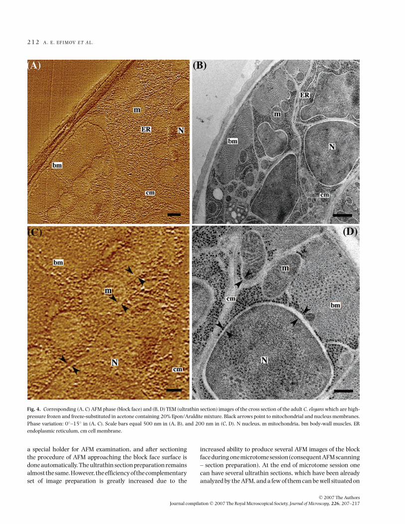
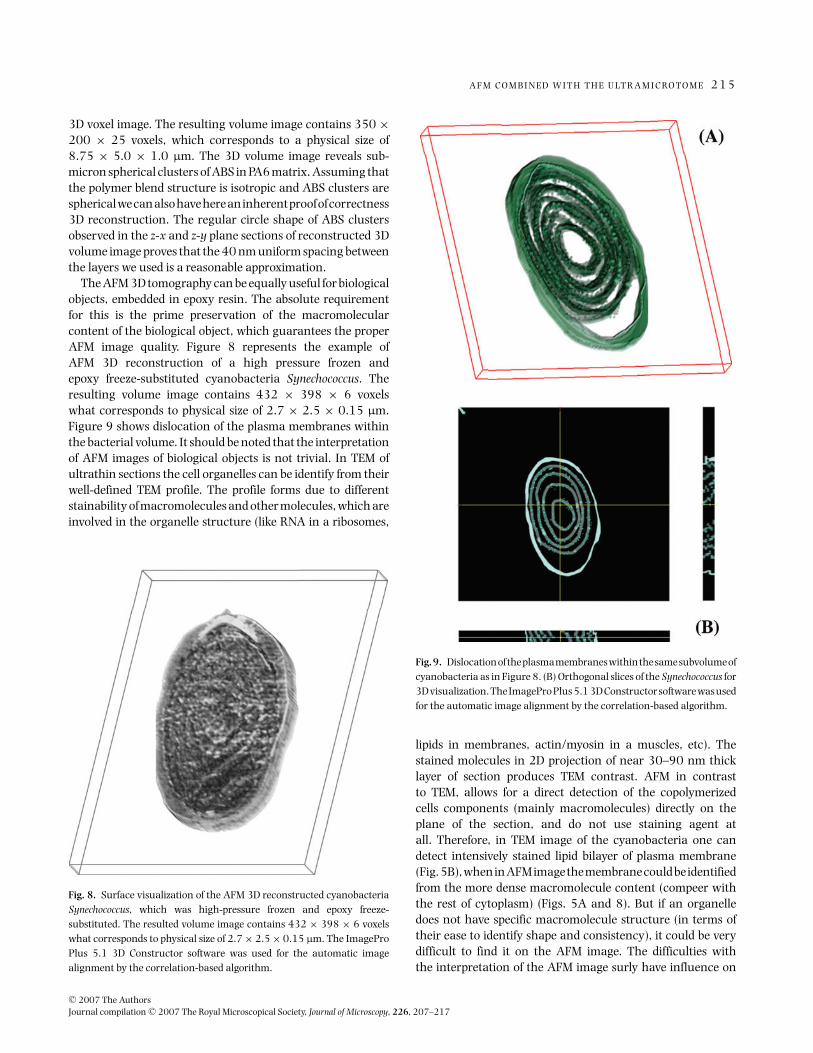
The AFM 3D tomography can be equally useful for biologicalobjects, embedded in epoxy resin. The absolute requirementfor this is the prime preservation of the macromolecularcontent of the biological object, which guarantees the properAFM image quality. Figure 8 represents the example ofAFM 3D reconstruction of a high pressure frozen andepoxy freeze-substituted cyanobacteria Synechococcus. Theresulting volume image contains 432 × 398 × 6 voxelswhat corresponds to physical size of 2.7 × 2.5 × 0.15 µm.Figure 9 shows dislocation of the plasma membranes withinthe bacterial volume. It should be noted that the interpretationof AFM images of biological objects is not trivial. In TEM ofultrathin sections the cell organelles can be identify from theirwell-defined TEM profile. The profile forms due to differentstainability of macromolecules and other molecules, which areinvolved in the organelle structure (like RNA in a ribosomes,
Fig. 8. Surface visualization of the AFM 3D reconstructed cyanobacteriaSynechococcus, which was high-pressure frozen and epoxy freeze-substituted. The resulted volume image contains 432 × 398 × 6 voxelswhat corresponds to physical size of 2.7 × 2.5 × 0.15 µm. The ImageProPlus 5.1 3D Constructor software was used for the automatic imagealignment by the correlation-based algorithm.
Fig.9. Dislocationoftheplasmamembraneswithinthesamesubvolumeofcyanobacteria as in Figure 8. (B) Orthogonal slices of the Synechococcus for3D visualization. The ImagePro Plus 5.1 3D Constructor software was usedfor the automatic image alignment by the correlation-based algorithm.
lipids in membranes, actin/myosin in a muscles, etc). Thestained molecules in 2D projection of near 30–90 nm thicklayer of section produces TEM contrast. AFM in contrastto TEM, allows for a direct detection of the copolymerizedcells components (mainly macromolecules) directly on theplane of the section, and do not use staining agent atall. Therefore, in TEM image of the cyanobacteria one candetect intensively stained lipid bilayer of plasma membrane(Fig. 5B), when in AFM image the membrane could be identifiedfrom the more dense macromolecule content (compeer withthe rest of cytoplasm) (Figs. 5A and 8). But if an organelledoes not have specific macromolecule structure (in terms oftheir ease to identify shape and consistency), it could be verydifficult to find it on the AFM image. The difficulties withthe interpretation of the AFM image surly have influence on
C© 2007 The AuthorsJournal compilation C© 2007 The Royal Microscopical Society, Journal of Microscopy, 226, 207–217
2 1 6 A . E . E F I M OV E T A L .
the interpretation of the whole AFM 3D tomography profile.From our point of view, this is the only limitation to using3D AFM tomography routinely in biology. Nevertheless, theunique opportunity provided by AFM in the detection of themacromolecular distribution within cell volume leads to adeeper understanding of entire cellular ultrastructure, goingfar beyond the possibility offered by TEM alone. This one-to-onecorrespondence of stained structure and their macromolecularcomposition in three dimensions should give the biologist avery powerful method to analyze nanoscale biostructure in thefuture.
4. Conclusion
Using a combination of different imaging methods in structuralbiology or polymer science almost always gives more, thaneach method alone. The new instrument described here, theNTEGRA Tomo, which is the conjugation of the conventionalSPM with the microtome, is the good illustration of such anidea. Apart from facilities, offered by each of these instruments,the NTEGRA Tomo provides a number of additional options,which can be appreciated in ultrastructural investigation on awide range of biological or polymer materials.
The first is the use this instrument for Serial SectionTomography. 3D reconstruction in the NTEGRA Tomo canbe obtained by automated block-face imaging combined withserial sectioning by the ultramicrotome. The step size can bevaried from 20 to 2000 nm thick, the sectioning/scanningcycle permitted to acquire up to 10 sequential images per hourand to obtain the nanotomography image reconstructed fromseveral tens of layer images within one measuring session.
The second is that the NTEGRA Tomo is a valid instrumentfor the precise detection (imaging) of an area of specialinterest within the volume of the sample with resolution ona nanometers scale. Although for embedded biological objectsan ultimate resolution of SPM depends mostly on the qualityof macromolecular preservation of the biomaterial duringsample preparation procedure, for most of polymer materialsit is comparable to TEM.
The possibility to routinely produce AFM/TEM comple-mentary sets of images for the correlative ultrastructuralanalysis of the biological or polymer materials is the thirdevident advantage of the NTEGRA Tomo. The NTEGRA Tomois proving to be an exciting tool, which is equally usefulfor the routine measurements of processes such as samplequality control, and for the more complex scientific sampleinvestigations.
Acknowledgements
We are very grateful to NT-MDT workshop for precisionmachining, Leica Microsystems, Austria, and NT-MDTcomputer group for the development of electronic hardwareand fruitful collaboration, Viktor Bykov, Sergey Saunin,Dmitriy Sokolov for fruitful discussions. We would like to thank
Martin Mueller for his decisive support during this work. Thehelp provided by Andrey B. Matsko, Marshall W. Bates andArtem Rudenko in the preparation of the manuscript is alsohighly appreciated.
References
Biel, S.S., Kawaschinski, K., Wittern, K.P., Hintze, U. & Wepf, R. (2003)From tissue to cellular ultrastructure: closing the gap between micro-and nanostructural imaging. J. Microsc. 212, 91–99.
Chen, Y., Cai, J., Zhao, T., Wang, C., Dong, S., Luo, S. & Chen, Z.W. (2005)Atomic force microscopy imaging and 3-D recostructions of serial thinsections of a single cell and its interior structures. Ultramicroscopy. 103,173–182.
Dittrich, M. & Sibler, S. (2005) Characterizing of cell surface groups of twopicocyanobacteria strains. J. Coll. Interface Sci. 286, 487–495.
Denk, W. & Horstmann, H. (2004) Serial block-face scanning electronmicroscopy to reconstruct three-dimensional tissue nanostructure. PloSBiol. 2(11), 1900–1909.
Hayat, M.A. (2000) Principles and Techniques of Electron Microscopy:Biological Applications, 4th ed. Cambridge University Press, New Jersey.
Heymann, J., Hayles, M., Gestmann, I., Giannuzzi, L., Lich, B. &Subramaniam, S. (2006) Site-specific 3D imaging of cells and tissueswith a dual beam microscope. J. Struct. Biol. 155(1), 63–73.
Hohenberg, H., Mannweiler, K. & Mueller, M. (1994) High-pressurefreezing of cell suspensions in cellulose capillary tubes. J. Microsc.175(1), 34–43.
Holzer, L., Indutnyi, F., Gasser, P., Munch, B. & Wegmann, M. (2004)Three-dimensional analysis of porous BaTiO3 ceramics using FIBnanotomography. J. Microsc. 216, 84–95.
Kaestner, A., Lehmann, P., Wyss, P. & Fluhler, H. (2003) Synchrotrontomography to map the pore structure of sandsamples. Geophys. Res.Abstracts. 5, 11095.
Koguchi, M., Kakibayashi, H., Tsuneta, R., Yamaoka, M., Niino, T., Tanaka,N., Kase, K. & Iwaki, M. (2001) Three-dimensional STEM for observingnanostructures. J. Electron Microsc. 50, 235–241.
Matsko, N. & Mueller, M. (2004) AFM of biological material embedded inepoxy resin. J. Struct. Biol. 146, 334–343.
Matsko, N. & Mueller, M. (2005) Epoxy resin as fixative during freeze-substitution. J. Struct. Biol. 152, 92–103.
Matsko, N.B. (2007) Atomic force microscopy applied to studymacromolecular content of embedded biologycal material.Ultramicroscopy, 107(2–3), 95–105.
Midgley, P.A. & Weyland, M. (2003) 3D electron microscopy in the physicalsciences: the development of Z-contrast and EFTEM tomography.Ultramicroscopy. 96, 413–431.
Miller, M.K. (2000) Atom-probe Tomography: Analysis at the Atomic level.Kluwer Academic/Plenum Press, New York.
Mou, J., Yang, J. & Shao, Z. (1995) Atomic force microscopy of cholera toxinB-oligomers bound to bilayers of biologically relevant lipids. J. Mol. Biol.248, 507–512.
Obst, M., Dittrich, M. & Kuehn, H. (2006) Calcium absorption and changesof the surface microtopography of cyanobacteria studied by AFM, CFMand TEM with respect to biogenic calcite nucleation. Geochem. Geophys.Geosyst. 7, 1–15.
Reimer, L. (1993) Image Formation in Low-Voltage Scanning ElectronMicroscopy (ed. by D. O’Shea). SPIE Optical Engineering Press,Washington D.C. TT12.
C© 2007 The AuthorsJournal compilation C© 2007 The Royal Microscopical Society, Journal of Microscopy, 226, 207–217

A F M C O M B I N E D W I T H T H E U LT R A M I C RO T O M E 2 1 7
Reviakine, I., Bergsma-Schutter, W. & Brisson, A. (1998) Growth of protein2-D crystals on supported planar lipid bilayers imaged in situ by AFM.J. Struct. Biol. 121, 356–361.
Reynolds, E. (1963) The use of lead citrate at high pH as an electron-opaquestain in electron microscopy. J. Cell Biol. 17, 208–212.
Roessler, F., Grossenbacher, R., Stanisic, M. & Walt, H. (1991) Correlativehistological and ultrastructural study of unusual changes in humantracheobronchial epithelium. Laryngoscope. 101, 473–479.
Sawyer, L.C. & Grubb, D.T. (1996) Polymer Microscopy. 2nd ed. Alden Press,Oxford.
Scheuring, S., Ringler, P., Borgina, M., Stahlberg, H., Muller, D.J., Agre, P.& Engel, A. (1999) High resolution AFM topographs of the Escherichiacoli water channel aquaporin Z. EMBO J. 18, 4981–4987.
Schmitt, L., Ludwig, M., Gaub, H.E. & Tampe, R. (2000) A metal-chelatingmicroscopy tip as a new toolbox for single-molecule experiments byatomic force microscopy. Biophys. J. 78, 3275–3285.
Schwarz, H. (1994) Immunolabelling of ultrathin resin sections forfluorescence and electron microscopy. Electron Microscopy 1994 ICEM13-Paris Les editions de physique, Les Ulis, France (ed. by B. Jouffrey & C.Colliex), 3, 233–256.
Sutton, S.R., Newville, M. & Rivers, M.L. (2003) Synchrotron X-raymicroscope analysis. Geophys. Res. Abstracts. 5, 13260.
Van Harreveld, A. & Crowell, J. (1964) Electron microscopy after rapidfreezing on a metal surface and substitution fixation. Anat. Rec. 149,381–386.
Walters, D.A., Cleveland, J.P., Thomson, N.H., Hansma, P.K., Wendman,M.A., Gurley, G. & Elings, V. (1996) Short cantilevers for atomic forcemicroscopy. Rev. Sci. Instrum. 67, 3583–3590.
Walz, T., Tittmann, P., Fuchs, K.H., Muller, D.J., Smith, B.L., Agre, P., Gross,H. & Engel, A. (1996) Surface topographies at subnanometer-resolutionreveal asymmetry and sidedness of aquaporin-1. J. Mol. Biol. 264, 907–918.
C© 2007 The AuthorsJournal compilation C© 2007 The Royal Microscopical Society, Journal of Microscopy, 226, 207–217