Embed Size (px)
Citation preview
v3.8x
WWW.HORUSVISION.COM 1 650-588-8862
ATrag User Manual
Version 3.8x for 1X, 2X and MX
November 5, 2009 © 2009 Horus Vision, LLC. All rights reserved. U.S. Patent No. 6,453,595
v3.8x
WWW.HORUSVISION.COM 2 650-588-8862
Contents
1. REQUIREMENTS.................................................................................................... 4
2. ATRAG VERSIONS................................................................................................. 5 1X – Basic Targeting Software for Hunting....................................................................... 5 2X – Advanced Targeting Software for Professionals ...................................................... 6 MX – Tactical Aiming Software ......................................................................................... 6
3. FIRST TIME START UP.......................................................................................... 7 Setting ATrag to Run from Soft (application) Button......................................................... 8 Creating Default INI and GUN Files.................................................................................. 8 Quitting the Program......................................................................................................... 8
4. UNITS OF MEASURE ............................................................................................. 9
5. PROGRAM CONTROLS....................................................................................... 10 Hard Buttons on the PDA................................................................................................ 10 General Controls on the Main Screen............................................................................. 10 General Controls on Parameter Assist Screens ............................................................. 12 Correcting Mistakes in Fields.......................................................................................... 13 The Main Menu ............................................................................................................... 13
6. BASIC USAGE – FIRST SHOT TARGET STRIKE!.............................................. 14 Gun and Ammo Data Screen.......................................................................................... 14 Atmospheric and Environmental Data Screen ................................................................ 14 Target Data Screen......................................................................................................... 15 Parameter Limits............................................................................................................. 16 Setting Up a Solution for Your Scope ............................................................................. 16 Relative Click Memory for Clicking Scopes .................................................................... 17
7. RANGE CARD ...................................................................................................... 18 Range Card Display........................................................................................................ 18 Range Card Setup .......................................................................................................... 18
8. PARAMETER ASSIST SCREENS........................................................................ 20 Target Range Assist ....................................................................................................... 20 Target Speed Assist........................................................................................................ 20 Muzzle Velocity vs. Temperature Interpolation ............................................................... 21 C1 Ballistic Coefficient vs. Distance Interpolation........................................................... 21
9. TRUING DROP.................................................................................................... 220 Main Menu ...................................................................................................................... 20 Truing Drop Screen......................................................................................................... 20 Finding Transonic Range from Range Card ................................................................... 21 Miscellaneous Functions................................................................................................. 21
10. GUNLISTS............................................................................................................. 21 What is a Gun and GunList?........................................................................................... 25 Switching Guns from the GunList ................................................................................... 25 Selecting Multiple Guns .................................................................................................. 26 Where is My Data Stored? Why Did My Changes Disappear?...................................... 26
v3.8x
WWW.HORUSVISION.COM 3 650-588-8862
Store a New Gun in the GunList ..................................................................................... 27 Modify a Gun Entry in the GunList .................................................................................. 27 Delete One or More Guns from the GunList ................................................................... 27 Add a Note to a Gun Entry.............................................................................................. 27 Saving and Retrieving the GunList on Memory Chip ...................................................... 27 Gun Files in easy to Read INI format.............................................................................. 28
11. CORIOLIS / MAGNUS AND SPIN DRIFT ............................................................. 29 Additional Gun and Load Parameters............................................................................. 30 Additional Target Parameters ......................................................................................... 30
12. MULTIPLE TARGETS........................................................................................... 31
13. DUAL WIND SPEED ............................................................................................. 32
14. INCLINATION ANGLE DUAL DISPLAY............................................................... 33
15. SORD .................................................................................................................... 34 SORD Setup Screen....................................................................................................... 34 SORD Display Screen .................................................................................................... 34
16. COMING SOON .................................................................................................... 35 Moon Phase, Sun/Moon Rise/Set Times ........................................................................ 35 ATrag for Second Plane Scopes..................................................................................... 35 Common Object Size Library .......................................................................................... 35
17. APPENDIX A – MUZZLE VELOCITY AND BALLISTIC COEFFICIENT’S .......... 36
18. APPENDIX B – ADDITIONAL NOTES FOR NOMAD AND RECON PDAS ........ 39 Power Button – Turn On/Off & Instant On ...................................................................... 39 Power Menu and Soft Reset ........................................................................................... 39 Clean Boot or Hard Reset............................................................................................... 40 Windows and OK Buttons ............................................................................................... 40 Soft Buttons .................................................................................................................... 40 Navigation Buttons.......................................................................................................... 40 Numeric Buttons Nomad................................................................................................. 41
v3.8x
WWW.HORUSVISION.COM 4 650-588-8862
1. REQUIREMENTS The current ATrag software, version 3.8x, has been tested to run on most handheld Personal Digital Assistants (PDAs) running PocketPC (version 2003 SE or later). For your protection and ours, programs from Horus Vision are copy-protected to preserve your security and our Intellectual
Property interests. ATrag is distributed on either Secured Digital (SD) or Compact Flash (CF) memory chips (CF only available for PocketPCs), so your PDA must support a SD or CF expansion slot. Each program is encoded with a unique serial number tied to the specific memory chip it is shipped on. If the program is copied from the chip, or is run without its corresponding chip in the expansion slot, it will not run. Because hardware varies between manufacturers, especially where the expansion slot is concerned, it is impossible to test every model on the market. If you experience any difficulties, please do not hesitate to contact us at 650-588-8862 or email us at [email protected]. We will do our best to accommodate all inquires.
v3.8x
WWW.HORUSVISION.COM 5 650-588-8862
2. ATRAG VERSIONS ATrag’s proprietary targeting formulas are based on William Davis’ life work as a US Army ballistics expert at ARDEC. During his career, he has put hundreds of thousands of live rounds into refining these calculations. The underlying algorithm has been cultivated by Davis to be accurate whether you are lobbing paintballs at 40 yards or reaching out beyond 3,000 yards with boat tail bullets. Our own extensive field trails have proven Davis’ calculations valid to 2,600 yards. These formulas take in all the factors governing bullet flight from the point of launch to target strike. Included amongst these are bullet weight, shape, and drag contributors, muzzle velocity, rifling twist rate and direction (as viewed from the chamber end of the barrel). Atmospheric considerations such as air density, humidity and range-wind are addressed, along with Earth ‘rotation effects’ (coriolis) and, of course, the location and behavior of the target. We built ATrag to be instantly and intuitively familiar so these parameters are entered through easy-to-use interfaces that makes sense the very first time you pick it up. Lightning-fast results are delivered in an equally uncluttered display. Think of it as an advanced fire control system in the palm of your hand. No matter what scope, gun, or load you might be shooting, ATrag is simply the best shooting assistance you could ever personally own.
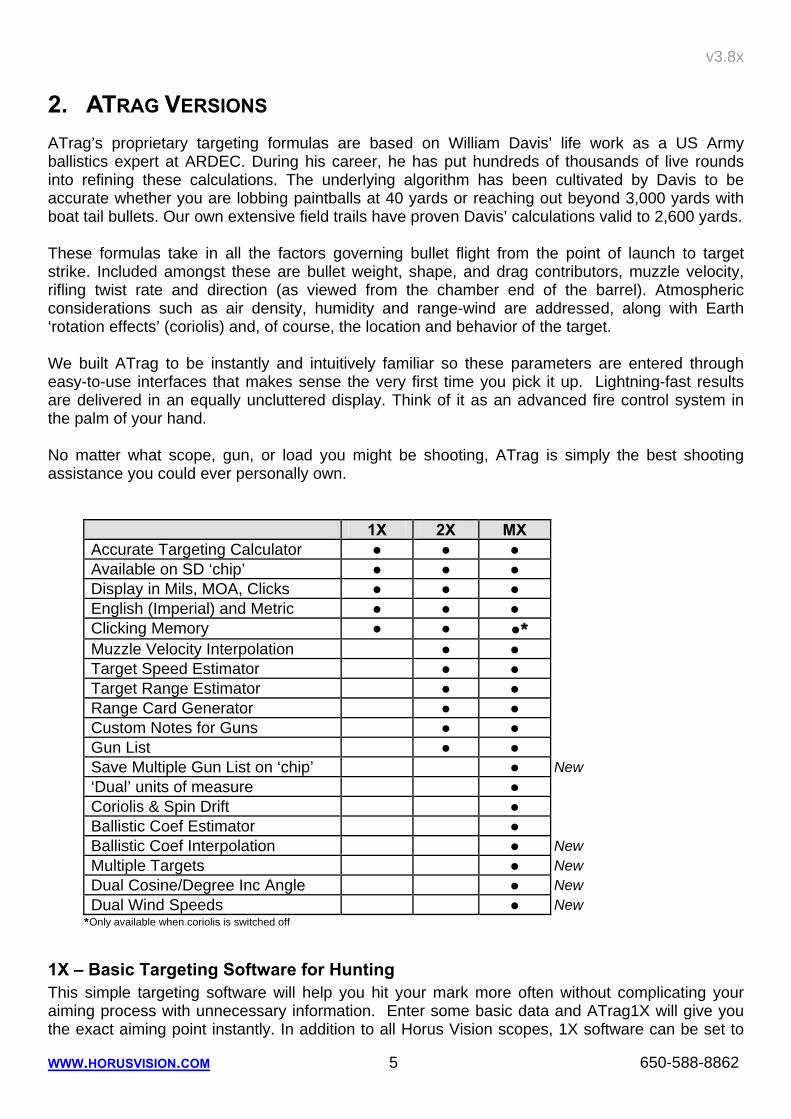
1X 2X MX Accurate Targeting Calculator ● ● ● Available on SD ‘chip’ ● ● ● Display in Mils, MOA, Clicks ● ● ● English (Imperial) and Metric ● ● ● Clicking Memory ● ● ●* Muzzle Velocity Interpolation ● ● Target Speed Estimator ● ● Target Range Estimator ● ● Range Card Generator ● ● Custom Notes for Guns ● ● Gun List ● ● Save Multiple Gun List on ‘chip’ ● New ‘Dual’ units of measure ● Coriolis & Spin Drift ● Ballistic Coef Estimator ● Ballistic Coef Interpolation ● New Multiple Targets ● New Dual Cosine/Degree Inc Angle ● New Dual Wind Speeds ● New
*Only available when coriolis is switched off
1X – Basic Targeting Software for Hunting This simple targeting software will help you hit your mark more often without complicating your aiming process with unnecessary information. Enter some basic data and ATrag1X will give you the exact aiming point instantly. In addition to all Horus Vision scopes, 1X software can be set to
v3.8x
WWW.HORUSVISION.COM 6 650-588-8862
work with any scope. Results can be shown in mils, TMOA, SMOA or in the exact number of elevation and windage clicks for knob adjustments. 1X also remembers your zero setting by showing relative changes across multiple adjustments.
2X – Advanced Targeting Software for Professionals Going beyond basic shooting, your calculation needs become more dependent on informed, accurate information. The 2X version incorporates ‘Assist Screens’ to help provide more accurate ranging, target-speed, and muzzle velocity information. We also recognize that advanced shooters will most likely wish to use more than one rifle per hunting trip or range activity, or indeed, simply wish to test and record multiple loads in the one firearm. Horus Vision’s 2X Advanced Targeting Software allows the shooter to store/save multiple gun/loads for easy switching between firearms and loads. For instance, you are shooting a .50 Cal. gun with both supersonic and subsonic loads. If you had the ability to save, and recall each load as discrete profiles, then you could simply switch profiles at the same time you switch rounds, without having to re-enter all the information. Along with keeping lists of profiles, the lists can be stored and retrieved as separate files on the program chip. ATrag2X also provides you with a come-up (range) card feature that allows you to easily generate shooting cards that can be taped to your gun for use in circumstances where you simply cannot, or do not want to use your PDA (hand held computer). Instead of having to re-enter the range for every different shot taken from a given gun/load combination, 2X displays a complete table of holdover values for different engagement ranges for that particular gun/load combination.
MX – Tactical Aiming Software At extremely long ranges where spin-drift, earth rotation and Magnus effects play a greater role, the MX version accommodates these effects. The MX also has a “dual” units feature that allows the shooter to use all parameters in English units but distances are expressed in Metric. This is handy for mil dot scopes. MX has features for engaging multiple targets, the ability to “bracket” with dual wind speed values, and an increase of parameter limits for even more extreme conditions. It also compensates for changes in C1 values over the flight of the bullet.
v3.8x
WWW.HORUSVISION.COM 7 650-588-8862
3. FIRST TIME START UP All ATrag software shipped on SD or CF memory cards are shipped setup and ready to use. If you bought a PDA from Horus Vision, the PDA should arrive fully charged with the chip already inserted in the expansion slot. The entire unit is fully prepped to run right out of the box. If you ordered the software chip on its own, then you will need to insert it into the PDA’s memory expansion slot. This will differ on each individual PDA. Please refer to your User’s Manual that came with the PDA that you own.
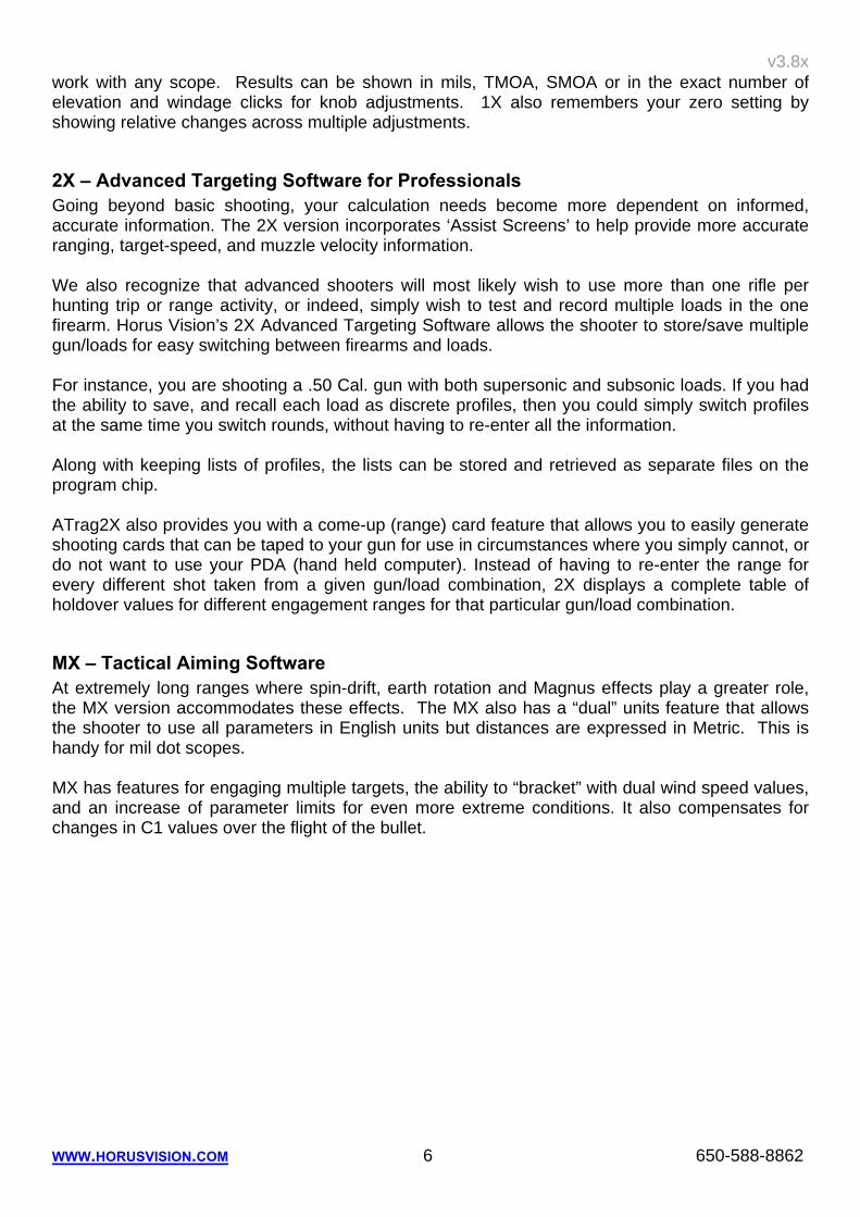
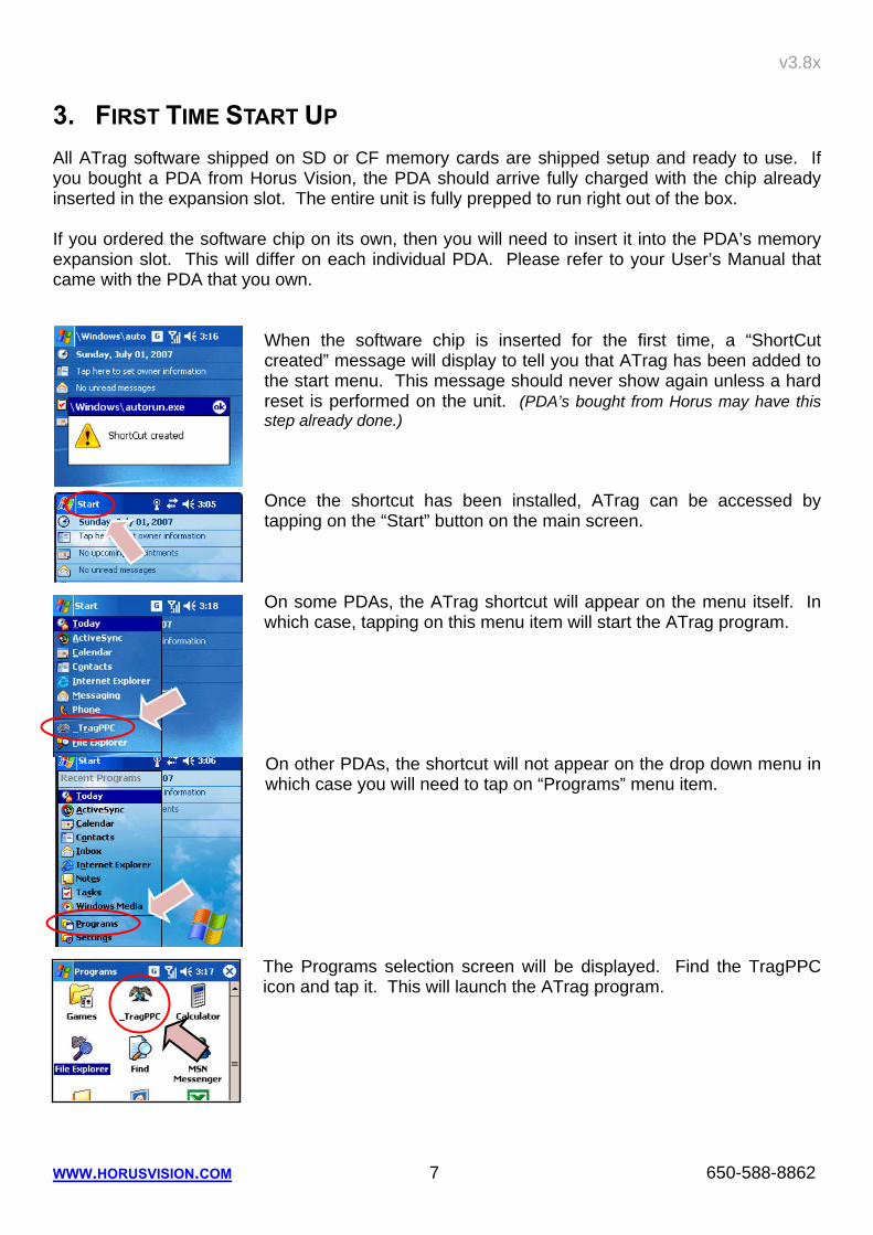
When the software chip is inserted for the first time, a “ShortCut created” message will display to tell you that ATrag has been added to the start menu. This message should never show again unless a hard reset is performed on the unit. (PDA’s bought from Horus may have this step already done.) Once the shortcut has been installed, ATrag can be accessed by tapping on the “Start” button on the main screen. On some PDAs, the ATrag shortcut will appear on the menu itself. In which case, tapping on this menu item will start the ATrag program. On other PDAs, the shortcut will not appear on the drop down menu in which case you will need to tap on “Programs” menu item. The Programs selection screen will be displayed. Find the TragPPC icon and tap it. This will launch the ATrag program.
v3.8x
WWW.HORUSVISION.COM 8 650-588-8862
Setting ATrag to Run from Soft (application) Button Most PDAs will allow you to assign programs to the buttons on either side of the Navigation Buttons. This is usually done through a System’s Settings screen. See your PDA user manual on how to access this screen. On the Recon and Nomad, ATrag is preset to launch from the right soft button (see appendix B).
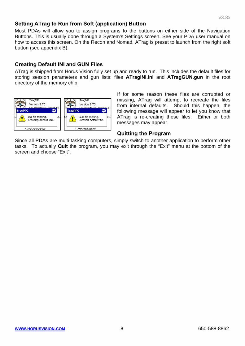
Creating Default INI and GUN Files ATrag is shipped from Horus Vision fully set up and ready to run. This includes the default files for storing session parameters and gun lists: files ATragINI.ini and ATragGUN.gun in the root directory of the memory chip.
If for some reason these files are corrupted or missing, ATrag will attempt to recreate the files from internal defaults. Should this happen, the following message will appear to let you know that ATrag is re-creating these files. Either or both messages may appear.
Quitting the Program Since all PDAs are multi-tasking computers, simply switch to another application to perform other tasks. To actually Quit the program, you may exit through the “Exit” menu at the bottom of the screen and choose “Exit”.
v3.8x
WWW.HORUSVISION.COM 9 650-588-8862
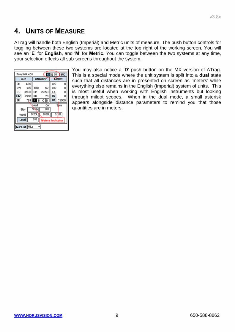
4. UNITS OF MEASURE ATrag will handle both English (Imperial) and Metric units of measure. The push button controls for toggling between these two systems are located at the top right of the working screen. You will see an ‘E’ for English, and ‘M’ for Metric. You can toggle between the two systems at any time, your selection effects all sub-screens throughout the system.
You may also notice a ‘D’ push button on the MX version of ATrag. This is a special mode where the unit system is split into a dual state such that all distances are in presented on screen as ‘meters’ while everything else remains in the English (Imperial) system of units. This is most useful when working with English instruments but looking through mildot scopes. When in the dual mode, a small asterisk appears alongside distance parameters to remind you that those quantities are in meters.
v3.8x
WWW.HORUSVISION.COM 10 650-588-8862
5. PROGRAM CONTROLS All PDAs now use the display screen as its primary user interface. Not only does it display information, it is also a Touch Screen that can accept general commands to direct the program, for both navigating around and across screens, and for input of data. A convenient way to enter data is via the PDA’s ‘graffiti’ area of the touch screen (please read your PDA documentation on how to do this for it really is worth learning). Each ATrag version provides on-screen controls to ease the need to learn ‘graffiti’ wherever it can.
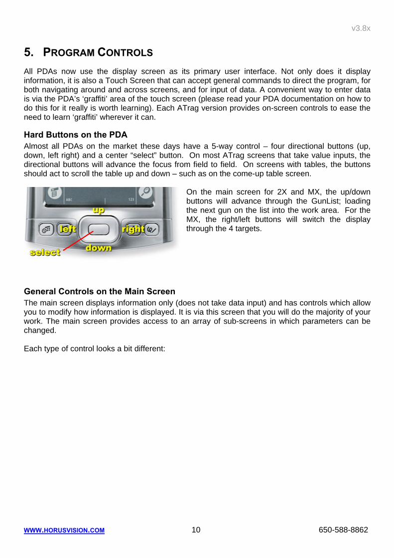
Hard Buttons on the PDA Almost all PDAs on the market these days have a 5-way control – four directional buttons (up, down, left right) and a center “select” button. On most ATrag screens that take value inputs, the directional buttons will advance the focus from field to field. On screens with tables, the buttons should act to scroll the table up and down – such as on the come-up table screen.
On the main screen for 2X and MX, the up/down buttons will advance through the GunList; loading the next gun on the list into the work area. For the MX, the right/left buttons will switch the display through the 4 targets.
General Controls on the Main Screen The main screen displays information only (does not take data input) and has controls which allow you to modify how information is displayed. It is via this screen that you will do the majority of your work. The main screen provides access to an array of sub-screens in which parameters can be changed. Each type of control looks a bit different:
v3.8x
WWW.HORUSVISION.COM 11 650-588-8862
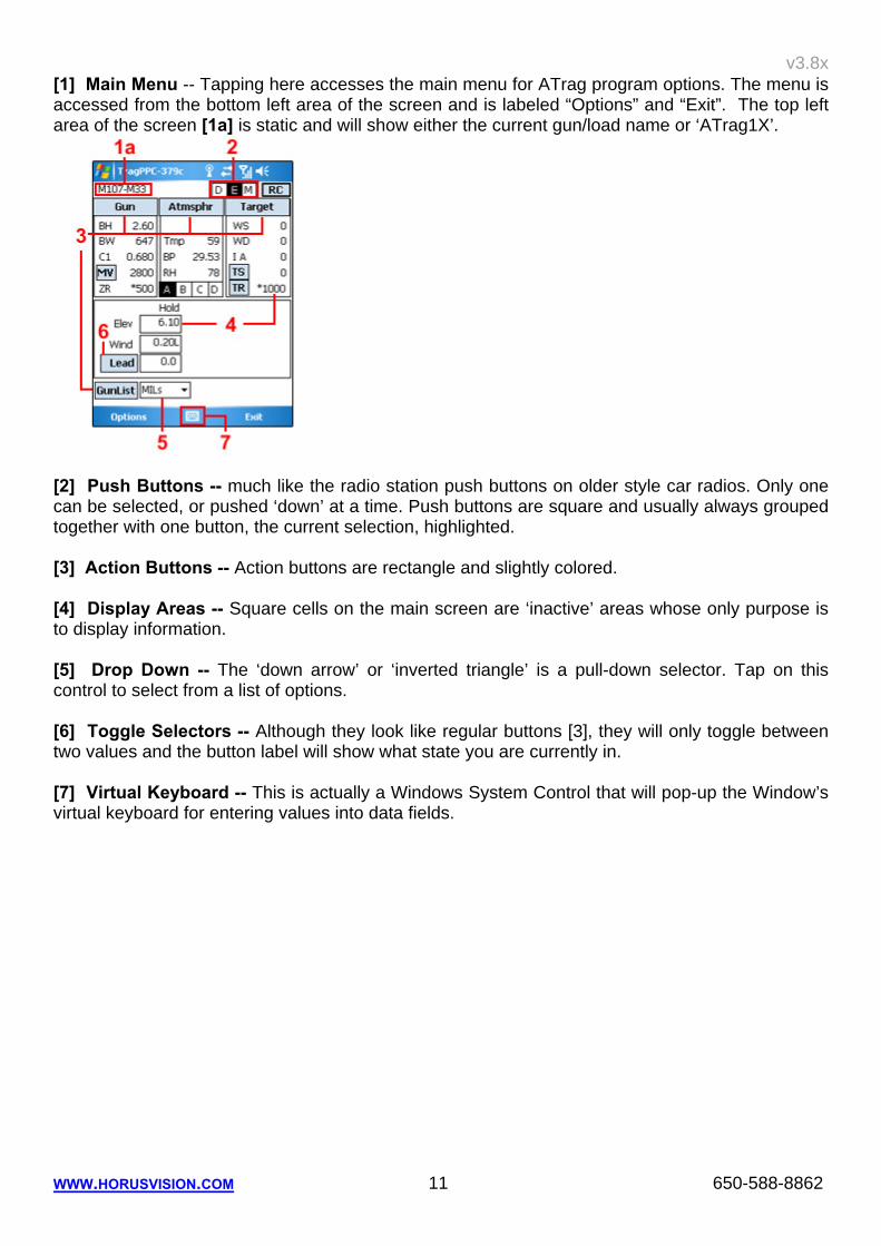
[1] Main Menu -- Tapping here accesses the main menu for ATrag program options. The menu is accessed from the bottom left area of the screen and is labeled “Options” and “Exit”. The top left area of the screen [1a] is static and will show either the current gun/load name or ‘ATrag1X’.
[2] Push Buttons -- much like the radio station push buttons on older style car radios. Only one can be selected, or pushed ‘down’ at a time. Push buttons are square and usually always grouped together with one button, the current selection, highlighted. [3] Action Buttons -- Action buttons are rectangle and slightly colored. [4] Display Areas -- Square cells on the main screen are ‘inactive’ areas whose only purpose is to display information. [5] Drop Down -- The ‘down arrow’ or ‘inverted triangle’ is a pull-down selector. Tap on this control to select from a list of options. [6] Toggle Selectors -- Although they look like regular buttons [3], they will only toggle between two values and the button label will show what state you are currently in. [7] Virtual Keyboard -- This is actually a Windows System Control that will pop-up the Window’s virtual keyboard for entering values into data fields.
v3.8x
WWW.HORUSVISION.COM 12 650-588-8862
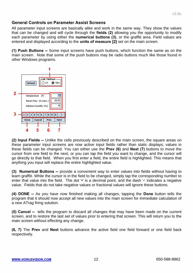
General Controls on Parameter Assist Screens All parameter input screens are basically alike and work in the same way. They show the values that can be changed and will cycle through the fields (2) allowing you the opportunity to modify each parameter by using either the numerical buttons (3), or the graffiti area. Field values are entered and displayed according to the units of measure [2] set on the main screen. (1) Push Buttons -- Some input screens have push buttons, which function the same as on the main screen. Note that some of the push buttons may be radio buttons much like those found in other Windows programs.
(2) Input Fields -- Unlike the cells previously described on the main screen, the square areas on these parameter input screens are now active input fields rather than static displays; values in these fields can be changed. You can either use the Prev (6) and Next (7) buttons to move the cursor from one field to the next, or you can tap the field you want to change, and the cursor will go directly to that field. When you first enter a field, the entire field is highlighted. This means that anything you input will replace the entire highlighted value. (3) Numerical Buttons -- provide a convenient way to enter values into fields without having to learn graffiti. While the cursor is in the field to be changed, simply tap the corresponding number to enter that value into the field. The dot ‘•’ is a decimal point, and the dash ‘-‘ indicates a negative value. Fields that do not take negative values or fractional values will ignore these buttons. (4) DONE -- As you have now finished making all changes, tapping the Done button tells the program that it should now accept all new values into the main screen for immediate calculation of a new ATrag firing solution. (5) Cancel -- tells the program to discard all changes that may have been made on the current screen, and to restore the last set of values prior to entering that screen. This will return you to the main screen without effecting any change. (6, 7) The Prev and Next buttons advance the active field one field forward or one field back respectively.
v3.8x
WWW.HORUSVISION.COM 13 650-588-8862
Correcting Mistakes in Fields Most active input fields have auto ‘error checking’ to ensure that values entered are compatible with the parameter involved. If you make a mistake, simply exit the field by tapping the Done button (4), then re-enter it to try again. Or you can learn how to erase a single number using a graffiti stroke. Or move out of the field, accept the error message, and try entering a new value.
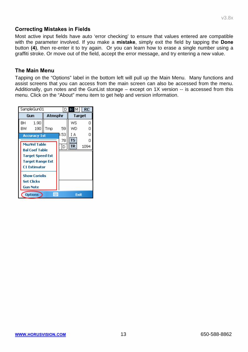
The Main Menu Tapping on the “Options” label in the bottom left will pull up the Main Menu. Many functions and assist screens that you can access from the main screen can also be accessed from the menu. Additionally, gun notes and the GunList storage – except on 1X version -- is accessed from this menu. Click on the “About” menu item to get help and version information.
v3.8x
WWW.HORUSVISION.COM 14 650-588-8862
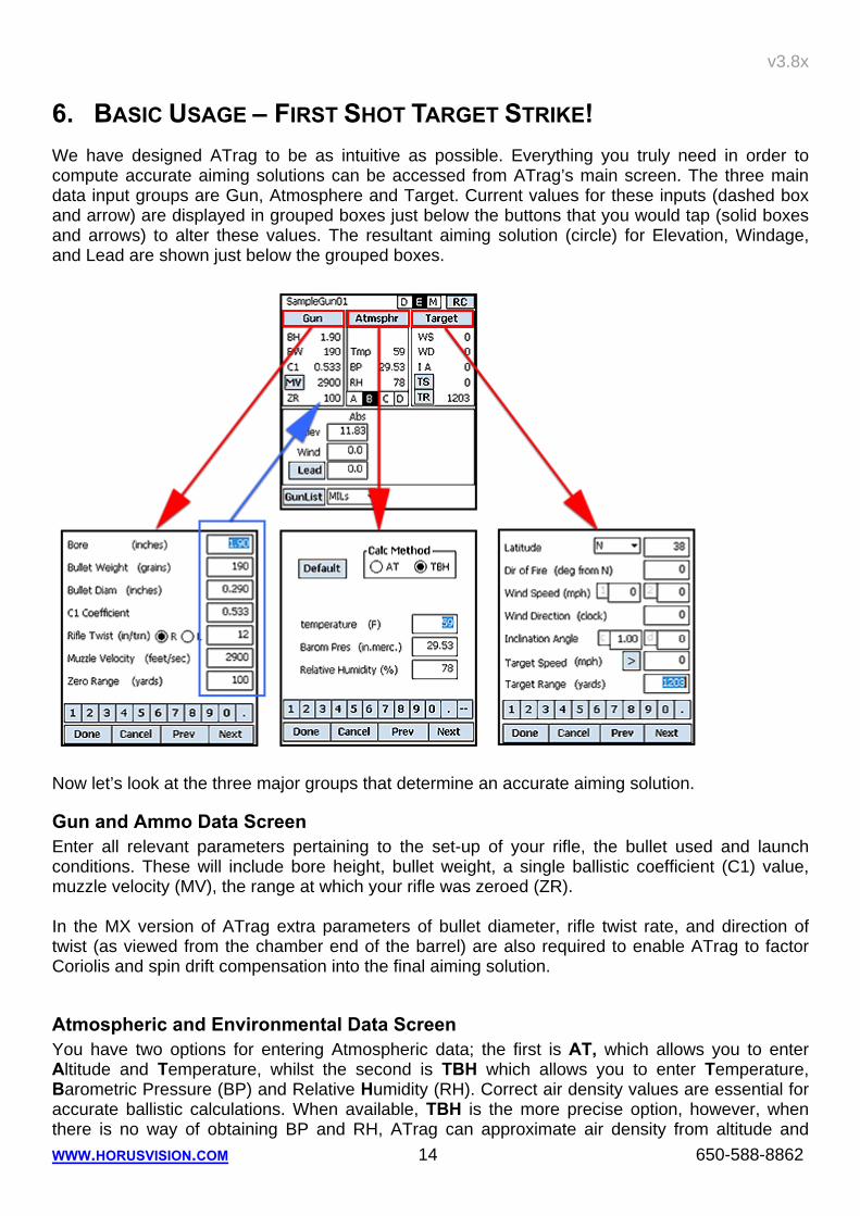
6. BASIC USAGE – FIRST SHOT TARGET STRIKE! We have designed ATrag to be as intuitive as possible. Everything you truly need in order to compute accurate aiming solutions can be accessed from ATrag’s main screen. The three main data input groups are Gun, Atmosphere and Target. Current values for these inputs (dashed box and arrow) are displayed in grouped boxes just below the buttons that you would tap (solid boxes and arrows) to alter these values. The resultant aiming solution (circle) for Elevation, Windage, and Lead are shown just below the grouped boxes.
Now let’s look at the three major groups that determine an accurate aiming solution.
Gun and Ammo Data Screen Enter all relevant parameters pertaining to the set-up of your rifle, the bullet used and launch conditions. These will include bore height, bullet weight, a single ballistic coefficient (C1) value, muzzle velocity (MV), the range at which your rifle was zeroed (ZR). In the MX version of ATrag extra parameters of bullet diameter, rifle twist rate, and direction of twist (as viewed from the chamber end of the barrel) are also required to enable ATrag to factor Coriolis and spin drift compensation into the final aiming solution.
Atmospheric and Environmental Data Screen You have two options for entering Atmospheric data; the first is AT, which allows you to enter Altitude and Temperature, whilst the second is TBH which allows you to enter Temperature, Barometric Pressure (BP) and Relative Humidity (RH). Correct air density values are essential for accurate ballistic calculations. When available, TBH is the more precise option, however, when there is no way of obtaining BP and RH, ATrag can approximate air density from altitude and
v3.8x
WWW.HORUSVISION.COM 15 650-588-8862
temperature. These parameters must be entered as closely as possible to the time of the shot as air temperature changes of even 10º F can put you off target at longer ranges.
Target Data Screen While data for the Gun and Atmosphere groups can be set into the PDA prior to engaging the target, it is only when you have your target in sight that you will be able to enter ‘moment of truth’ data such as wind speed, wind direction, uphill/downhill angle, distance to target as well as target speed and direction. The Target Speed’s right chevron ‘>’ indicates the direction the target is moving when seen through the scope (in this case, left to right). Tapping this chevron will toggle the direction. Wind Direction is expressed in clock points. This illustration shows how to determine the direction. Wind direction always uses the ‘axis of the barrel bore’ as its frame of reference, hence the wind direction is a ‘relative’ direction rather than an absolute direction. Within this ‘axis of the
bore’ reference system, wind is always described in terms of where it is coming from. So the direction of a right-to-left wind is therefore deemed to be coming from 3 o’clock and a wind blowing directly into your face would be coming from 12 o’clock.
In the MX version, extra parameters are provided for Magnus and coriolis corrections. Target Location is expressed as Hemisphere (North or South) and Latitude (0º at the equator to 90º at the poles).
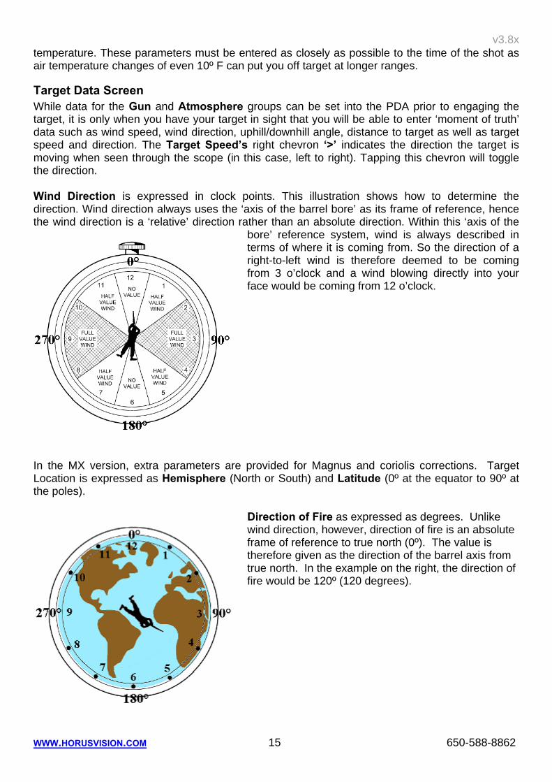
Direction of Fire as expressed as degrees. Unlike wind direction, however, direction of fire is an absolute frame of reference to true north (0º). The value is therefore given as the direction of the barrel axis from true north. In the example on the right, the direction of fire would be 120º (120 degrees).
v3.8x
WWW.HORUSVISION.COM 16 650-588-8862
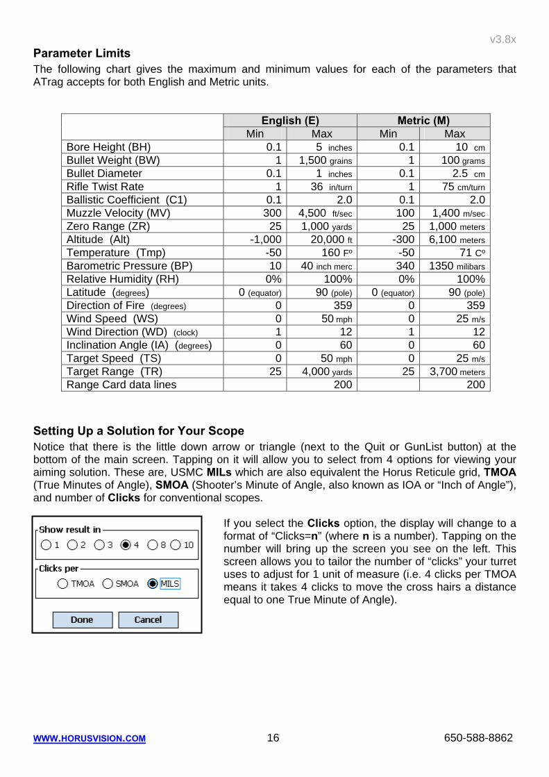
Parameter Limits The following chart gives the maximum and minimum values for each of the parameters that ATrag accepts for both English and Metric units.
English (E) Metric (M) Min Max Min Max
Bore Height (BH) 0.1 5 inches 0.1 10 cmBullet Weight (BW) 1 1,500 grains 1 100 gramsBullet Diameter 0.1 1 inches 0.1 2.5 cmRifle Twist Rate 1 36 in/turn 1 75 cm/turnBallistic Coefficient (C1) 0.1 2.0 0.1 2.0Muzzle Velocity (MV) 300 4,500 ft/sec 100 1,400 m/secZero Range (ZR) 25 1,000 yards 25 1,000 metersAltitude (Alt) -1,000 20,000 ft -300 6,100 metersTemperature (Tmp) -50 160 Fº -50 71 CºBarometric Pressure (BP) 10 40 inch merc 340 1350 milibarsRelative Humidity (RH) 0% 100% 0% 100%Latitude (degrees) 0 (equator) 90 (pole) 0 (equator) 90 (pole)Direction of Fire (degrees) 0 359 0 359Wind Speed (WS) 0 50 mph 0 25 m/sWind Direction (WD) (clock) 1 12 1 12Inclination Angle (IA) (degrees) 0 60 0 60Target Speed (TS) 0 50 mph 0 25 m/sTarget Range (TR) 25 4,000 yards 25 3,700 metersRange Card data lines 200 200
Setting Up a Solution for Your Scope Notice that there is the little down arrow or triangle (next to the Quit or GunList button) at the bottom of the main screen. Tapping on it will allow you to select from 4 options for viewing your aiming solution. These are, USMC MILs which are also equivalent the Horus Reticule grid, TMOA (True Minutes of Angle), SMOA (Shooter’s Minute of Angle, also known as IOA or “Inch of Angle”), and number of Clicks for conventional scopes.
If you select the Clicks option, the display will change to a format of “Clicks=n” (where n is a number). Tapping on the number will bring up the screen you see on the left. This screen allows you to tailor the number of “clicks” your turret uses to adjust for 1 unit of measure (i.e. 4 clicks per TMOA means it takes 4 clicks to move the cross hairs a distance equal to one True Minute of Angle).
v3.8x
WWW.HORUSVISION.COM 17 650-588-8862
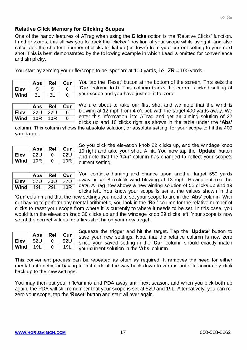
Relative Click Memory for Clicking Scopes One of the handy features of ATrag when using the Clicks option is the ‘Relative Clicks’ function. In other words, this allows you to track the ‘clicked’ position of your scope while using it, and also calculates the shortest number of clicks to dial up (or down) from your current setting to your next shot. This is best demonstrated by the following example in which Lead is omitted for convenience and simplicity. You start by zeroing your rifle/scope to be ‘spot on’ at 100 yards, i.e., ZR = 100 yards.
You tap the ‘Reset’ button at the bottom of the screen. This sets the ‘Cur’ column to 0. This column tracks the current clicked setting of your scope and you have just set it to ‘zero’. We are about to take our first shot and we note that the wind is blowing at 12 mph from 4 o’clock with the target 400 yards away. We enter this information into ATrag and get an aiming solution of 22 clicks up and 10 clicks right as shown in the table under the ‘Abs’
column. This column shows the absolute solution, or absolute setting, for your scope to hit the 400 yard target.
So you click the elevation knob 22 clicks up, and the windage knob 10 right and take your shot. A hit. You now tap the ‘Update’ button and note that the ‘Cur’ column has changed to reflect your scope’s current setting.
You continue hunting and chance upon another target 650 yards away, in an 8 o’clock wind blowing at 13 mph. Having entered this data, ATrag now shows a new aiming solution of 52 clicks up and 19 clicks left. You know your scope is set at the values shown in the
‘Cur’ column and that the new settings you need to set your scope to are in the ‘Abs’ column. With out having to perform any mental arithmetic, you look in the ‘Rel’ column for the relative number of clicks to reset your scope from where it is currently to where it needs to be set. In this case, you would turn the elevation knob 30 clicks up and the windage knob 29 clicks left. Your scope is now set at the correct values for a first-shot hit on your new target.
Squeeze the trigger and hit the target. Tap the ‘Update’ button to save your new settings. Note that the relative column is now zero since your saved setting in the ‘Cur’ column should exactly match your current solution in the ‘Abs’ column.
This convenient process can be repeated as often as required. It removes the need for either mental arithmetic, or having to first click all the way back down to zero in order to accurately click back up to the new settings. You may then put your rifle/ammo and PDA away until next season, and when you pick both up again, the PDA will still remember that your scope is set at 52U and 19L. Alternatively, you can re-zero your scope, tap the ‘Reset’ button and start all over again.
Abs Rel Cur Elev 5 5 0 Wind 3L 3L 0
Abs Rel Cur Elev 22U 22U 0 Wind 10R 10R 0
Abs Rel Cur Elev 22U 0 22U Wind 10R 0 10R
Abs Rel Cur Elev 52U 30U 22U Wind 19L 29L 10R
Abs Rel Cur Elev 52U 0 52U Wind 19L 0 19L
v3.8x
WWW.HORUSVISION.COM 18 650-588-8862
7. RANGE CARD Range Card Display
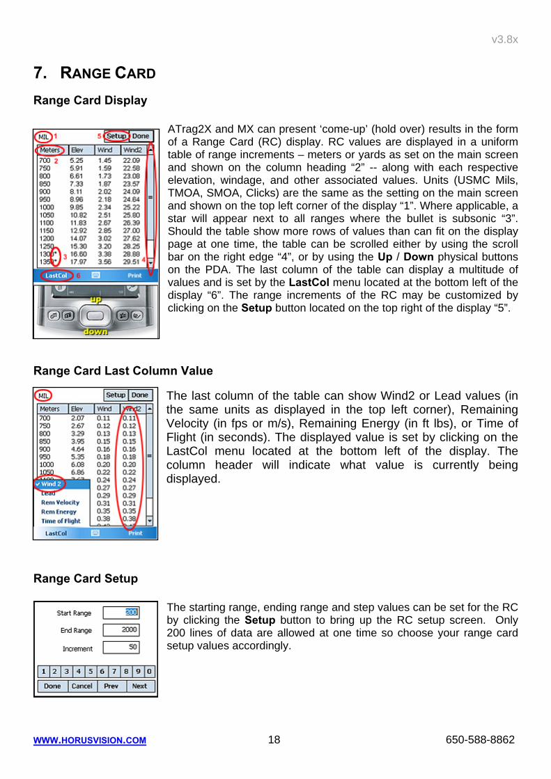
ATrag2X and MX can present ‘come-up’ (hold over) results in the form of a Range Card (RC) display. RC values are displayed in a uniform table of range increments – meters or yards as set on the main screen and shown on the column heading “2” -- along with each respective elevation, windage, and other associated values. Units (USMC Mils, TMOA, SMOA, Clicks) are the same as the setting on the main screen and shown on the top left corner of the display “1”. Where applicable, a star will appear next to all ranges where the bullet is subsonic “3”. Should the table show more rows of values than can fit on the display page at one time, the table can be scrolled either by using the scroll bar on the right edge “4”, or by using the Up / Down physical buttons on the PDA. The last column of the table can display a multitude of values and is set by the LastCol menu located at the bottom left of the display “6”. The range increments of the RC may be customized by clicking on the Setup button located on the top right of the display “5”.
Range Card Last Column Value
The last column of the table can show Wind2 or Lead values (in the same units as displayed in the top left corner), Remaining Velocity (in fps or m/s), Remaining Energy (in ft lbs), or Time of Flight (in seconds). The displayed value is set by clicking on the LastCol menu located at the bottom left of the display. The column header will indicate what value is currently being displayed.
Range Card Setup
The starting range, ending range and step values can be set for the RC by clicking the Setup button to bring up the RC setup screen. Only 200 lines of data are allowed at one time so choose your range card setup values accordingly.
v3.8x
WWW.HORUSVISION.COM 19 650-588-8862
Saving/Printing Range Card
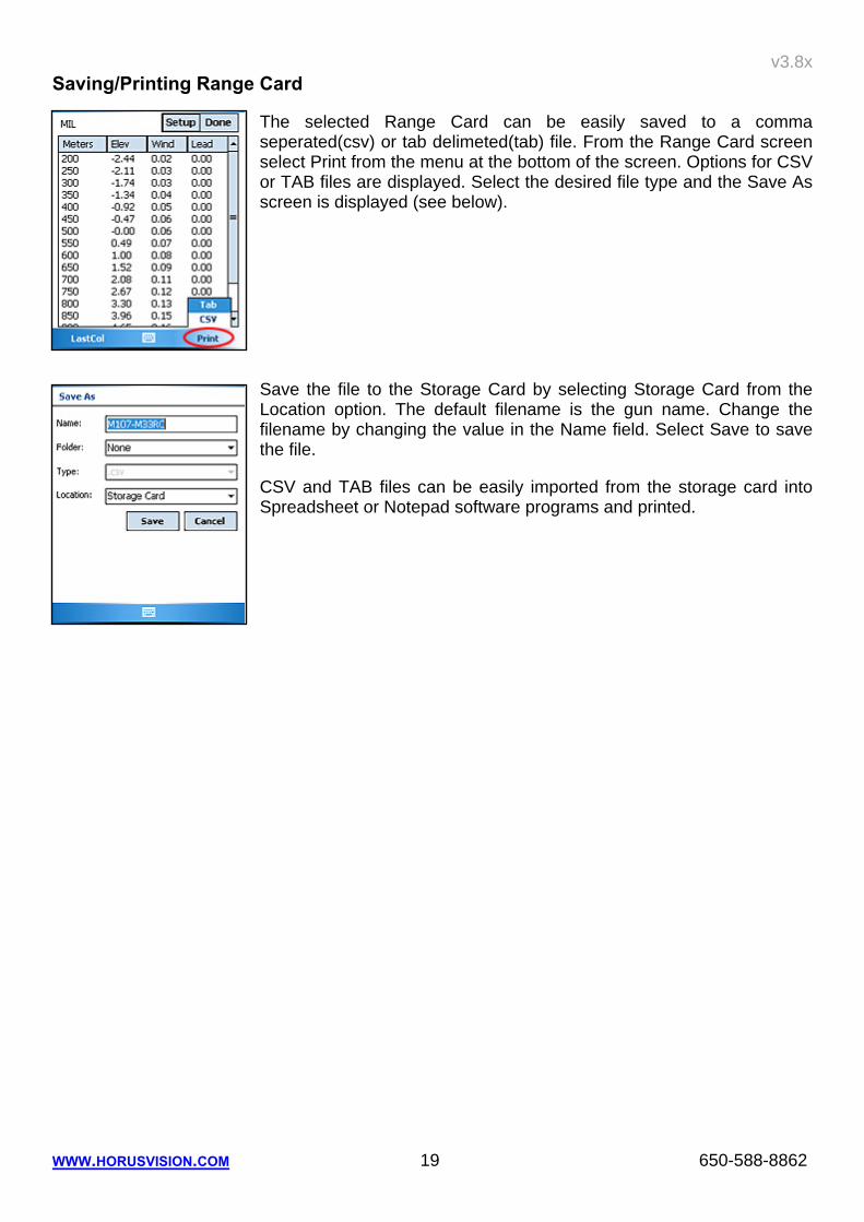
The selected Range Card can be easily saved to a comma seperated(csv) or tab delimeted(tab) file. From the Range Card screen select Print from the menu at the bottom of the screen. Options for CSV or TAB files are displayed. Select the desired file type and the Save As screen is displayed (see below).
Save the file to the Storage Card by selecting Storage Card from the Location option. The default filename is the gun name. Change the filename by changing the value in the Name field. Select Save to save the file.
CSV and TAB files can be easily imported from the storage card into Spreadsheet or Notepad software programs and printed.
v3.8x
WWW.HORUSVISION.COM 20 650-588-8862
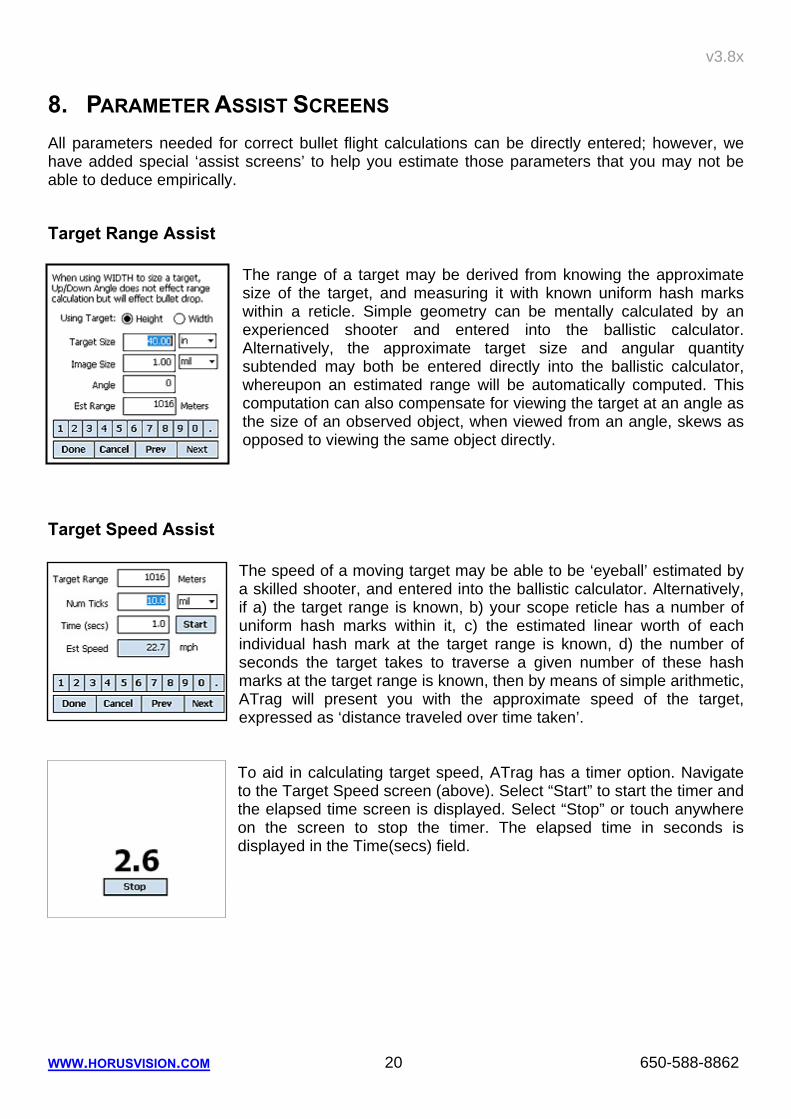
8. PARAMETER ASSIST SCREENS All parameters needed for correct bullet flight calculations can be directly entered; however, we have added special ‘assist screens’ to help you estimate those parameters that you may not be able to deduce empirically.
Target Range Assist The range of a target may be derived from knowing the approximate size of the target, and measuring it with known uniform hash marks within a reticle. Simple geometry can be mentally calculated by an experienced shooter and entered into the ballistic calculator. Alternatively, the approximate target size and angular quantity subtended may both be entered directly into the ballistic calculator, whereupon an estimated range will be automatically computed. This computation can also compensate for viewing the target at an angle as the size of an observed object, when viewed from an angle, skews as opposed to viewing the same object directly.
Target Speed Assist
The speed of a moving target may be able to be ‘eyeball’ estimated by a skilled shooter, and entered into the ballistic calculator. Alternatively, if a) the target range is known, b) your scope reticle has a number of uniform hash marks within it, c) the estimated linear worth of each individual hash mark at the target range is known, d) the number of seconds the target takes to traverse a given number of these hash marks at the target range is known, then by means of simple arithmetic, ATrag will present you with the approximate speed of the target, expressed as ‘distance traveled over time taken’.
To aid in calculating target speed, ATrag has a timer option. Navigate to the Target Speed screen (above). Select “Start” to start the timer and the elapsed time screen is displayed. Select “Stop” or touch anywhere on the screen to stop the timer. The elapsed time in seconds is displayed in the Time(secs) field.
v3.8x
WWW.HORUSVISION.COM 21 650-588-8862
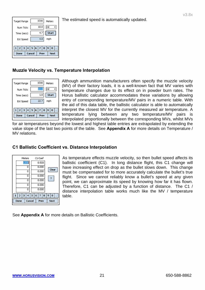
The estimated speed is automatically updated.
Muzzle Velocity vs. Temperature Interpolation
Although ammunition manufacturers often specify the muzzle velocity (MV) of their factory loads, it is a well-known fact that MV varies with temperature changes due to its effect on in powder burn rates. The Horus ballistic calculator accommodates these variations by allowing entry of corresponding temperature/MV pairs in a numeric table. With the aid of this data table, the ballistic calculator is able to automatically interpret the closest MV for the currently measured air temperature. A temperature lying between any two temperature/MV pairs is interpolated proportionally between the corresponding MVs, whilst MVs
for air temperatures beyond the lowest and highest table entries are extrapolated by extending the value slope of the last two points of the table. See Appendix A for more details on Temperature / MV relations.
C1 Ballistic Coefficient vs. Distance Interpolation As temperature effects muzzle velocity, so then bullet speed affects its ballistic coefficient (C1). In long distance flight, this C1 change will have increasing effect on drop as the bullet slows down. This change must be compensated for to more accurately calculate the bullet’s true flight. Since we cannot reliably know a bullet’s speed at any given point, we can approximate its speed by knowing how far it has flown. Therefore, C1 can be adjusted by a function of distance. The C1 / distance interpolation table works much like the MV / temperature table.
See Appendix A for more details on Ballistic Coefficients.
v3.8x
WWW.HORUSVISION.COM 22 650-588-8862
9. TRUING DROP VALUES ATragMX has a tool for determining true muzzle velocity (MV) or ballistic coefficient (C1), referred to here as “Truing Drop”. As discussed in previous chapters, the ATrag series of programs yields accurate elevation holds for your particular gun and cartridge in any given set of conditions. The more accurate the information going in, the more likely the firing solution provided by ATrag will be a first-round, center hit. Often when deployed or in the field developing data for a new gun or load, information such as MV and C1 isn’t readily available. The knowledge either the MV or C1 component along with actual bullet drop at one or more ranges can be used to determine the missing element. For example, if the shooter has a static C1 value from manufacturer-published tables, he can shoot at known distances (beyond zero range) and physically measure drop from point of aim. Those 2 variables- C1 and drop- can then be input into ATragMX and a true muzzle velocity derived. Likewise, input of a known MV and drop value can yield a true C1 value. Trag uses these 3 variables as the foundation for very accurate firing solutions when conducting field or tactical shooting at all distances.
Main Menu
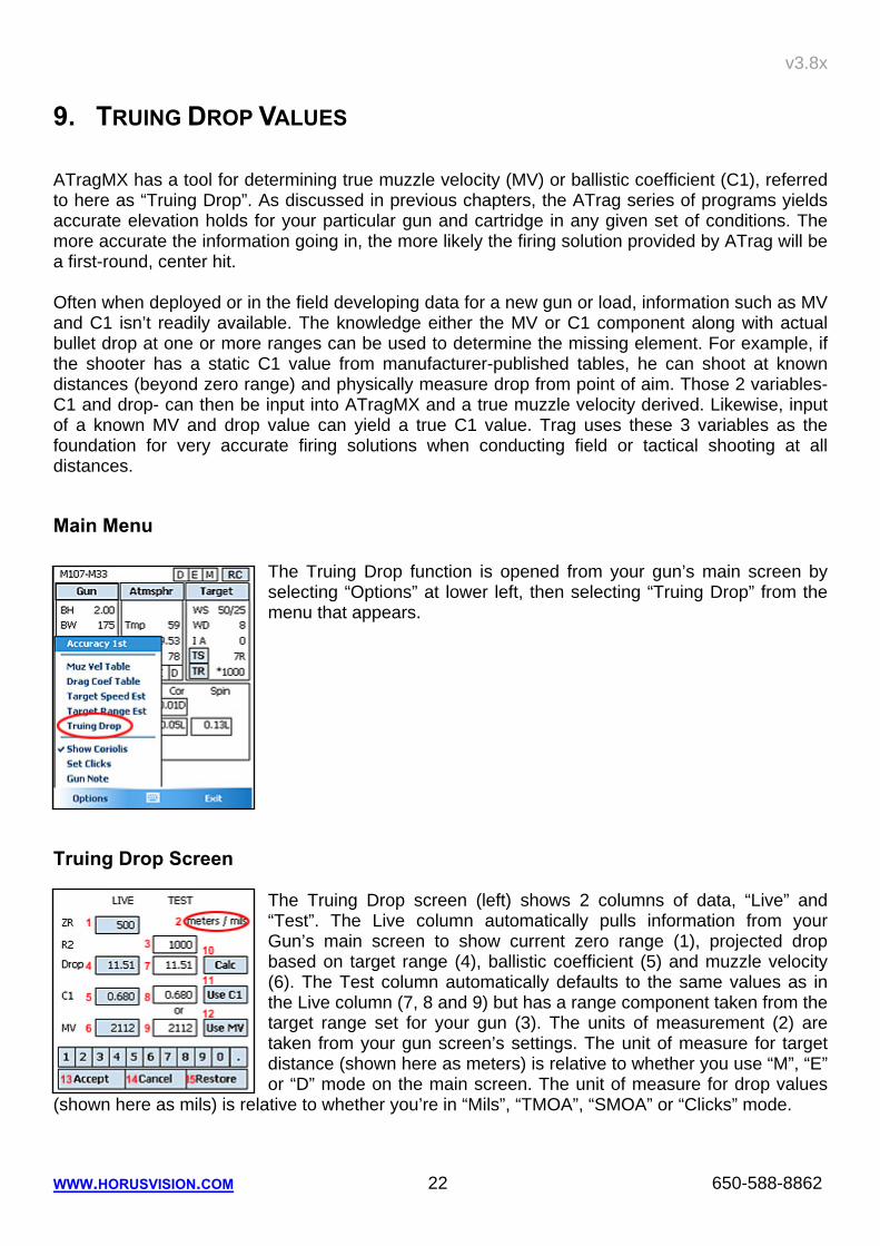
The Truing Drop function is opened from your gun’s main screen by selecting “Options” at lower left, then selecting “Truing Drop” from the menu that appears.
Truing Drop Screen
The Truing Drop screen (left) shows 2 columns of data, “Live” and “Test”. The Live column automatically pulls information from your Gun’s main screen to show current zero range (1), projected drop based on target range (4), ballistic coefficient (5) and muzzle velocity (6). The Test column automatically defaults to the same values as in the Live column (7, 8 and 9) but has a range component taken from the target range set for your gun (3). The units of measurement (2) are taken from your gun screen’s settings. The unit of measure for target distance (shown here as meters) is relative to whether you use “M”, “E” or “D” mode on the main screen. The unit of measure for drop values
(shown here as mils) is relative to whether you’re in “Mils”, “TMOA”, “SMOA” or “Clicks” mode.
v3.8x
WWW.HORUSVISION.COM 23 650-588-8862
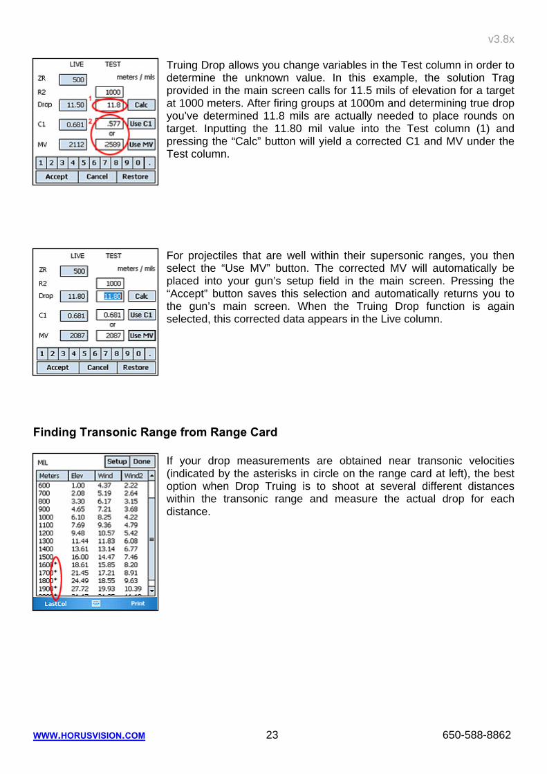
Truing Drop allows you change variables in the Test column in order to determine the unknown value. In this example, the solution Trag provided in the main screen calls for 11.5 mils of elevation for a target at 1000 meters. After firing groups at 1000m and determining true drop you’ve determined 11.8 mils are actually needed to place rounds on target. Inputting the 11.80 mil value into the Test column (1) and pressing the “Calc” button will yield a corrected C1 and MV under the Test column.
For projectiles that are well within their supersonic ranges, you then select the “Use MV” button. The corrected MV will automatically be placed into your gun’s setup field in the main screen. Pressing the “Accept” button saves this selection and automatically returns you to the gun’s main screen. When the Truing Drop function is again selected, this corrected data appears in the Live column.
Finding Transonic Range from Range Card If your drop measurements are obtained near transonic velocities (indicated by the asterisks in circle on the range card at left), the best option when Drop Truing is to shoot at several different distances within the transonic range and measure the actual drop for each distance.
v3.8x
WWW.HORUSVISION.COM 24 650-588-8862
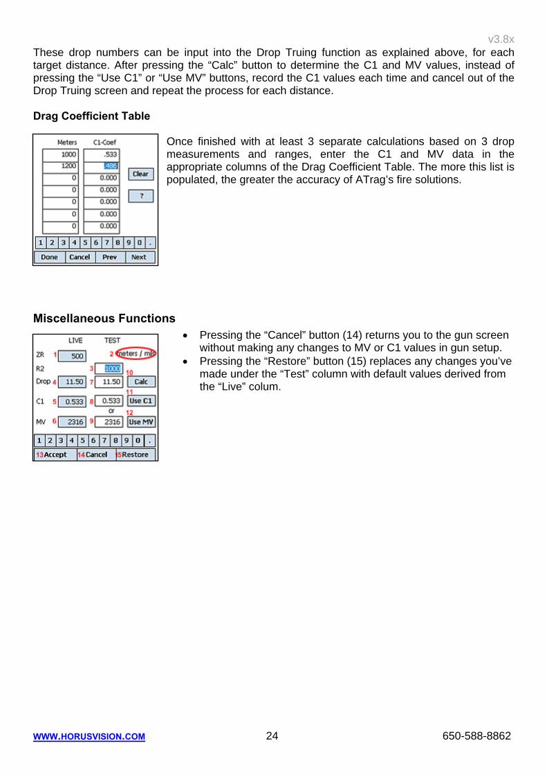
These drop numbers can be input into the Drop Truing function as explained above, for each target distance. After pressing the “Calc” button to determine the C1 and MV values, instead of pressing the “Use C1” or “Use MV” buttons, record the C1 values each time and cancel out of the Drop Truing screen and repeat the process for each distance. Drag Coefficient Table
Once finished with at least 3 separate calculations based on 3 drop measurements and ranges, enter the C1 and MV data in the appropriate columns of the Drag Coefficient Table. The more this list is populated, the greater the accuracy of ATrag’s fire solutions.
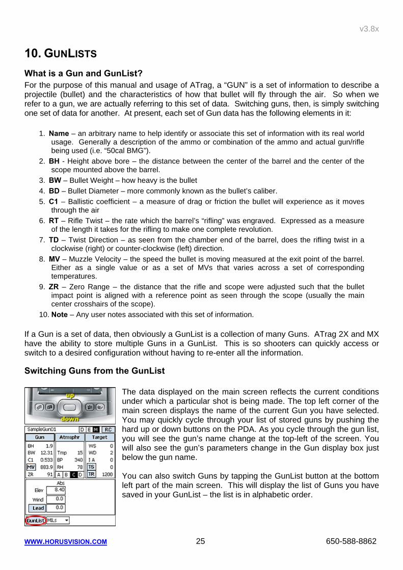
Miscellaneous Functions • Pressing the “Cancel” button (14) returns you to the gun screen
without making any changes to MV or C1 values in gun setup. • Pressing the “Restore” button (15) replaces any changes you’ve
made under the “Test” column with default values derived from the “Live” colum.
v3.8x
WWW.HORUSVISION.COM 25 650-588-8862
10. GUNLISTS What is a Gun and GunList? For the purpose of this manual and usage of ATrag, a “GUN” is a set of information to describe a projectile (bullet) and the characteristics of how that bullet will fly through the air. So when we refer to a gun, we are actually referring to this set of data. Switching guns, then, is simply switching one set of data for another. At present, each set of Gun data has the following elements in it:
1. Name – an arbitrary name to help identify or associate this set of information with its real world usage. Generally a description of the ammo or combination of the ammo and actual gun/rifle being used (i.e. “50cal BMG”).
2. BH - Height above bore – the distance between the center of the barrel and the center of the scope mounted above the barrel.
3. BW – Bullet Weight – how heavy is the bullet 4. BD – Bullet Diameter – more commonly known as the bullet’s caliber. 5. C1 – Ballistic coefficient – a measure of drag or friction the bullet will experience as it moves
through the air 6. RT – Rifle Twist – the rate which the barrel’s “rifling” was engraved. Expressed as a measure
of the length it takes for the rifling to make one complete revolution. 7. TD – Twist Direction – as seen from the chamber end of the barrel, does the rifling twist in a
clockwise (right) or counter-clockwise (left) direction. 8. MV – Muzzle Velocity – the speed the bullet is moving measured at the exit point of the barrel.
Either as a single value or as a set of MVs that varies across a set of corresponding temperatures.
9. ZR – Zero Range – the distance that the rifle and scope were adjusted such that the bullet impact point is aligned with a reference point as seen through the scope (usually the main center crosshairs of the scope).
10. Note – Any user notes associated with this set of information. If a Gun is a set of data, then obviously a GunList is a collection of many Guns. ATrag 2X and MX have the ability to store multiple Guns in a GunList. This is so shooters can quickly access or switch to a desired configuration without having to re-enter all the information.
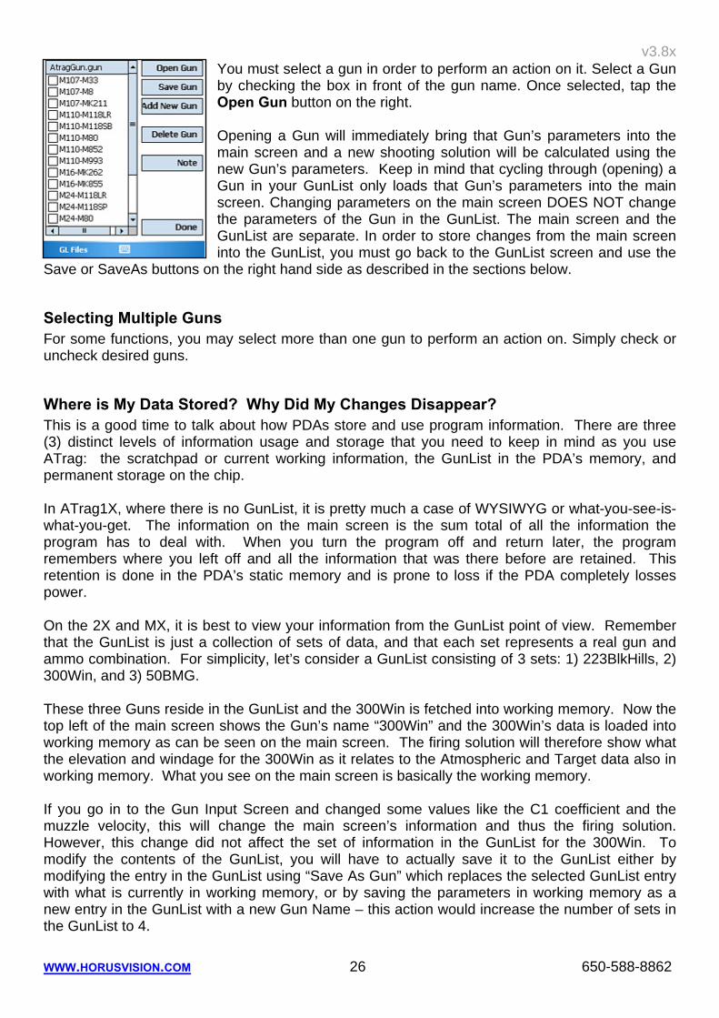
Switching Guns from the GunList
The data displayed on the main screen reflects the current conditions under which a particular shot is being made. The top left corner of the main screen displays the name of the current Gun you have selected. You may quickly cycle through your list of stored guns by pushing the hard up or down buttons on the PDA. As you cycle through the gun list, you will see the gun’s name change at the top-left of the screen. You will also see the gun’s parameters change in the Gun display box just below the gun name. You can also switch Guns by tapping the GunList button at the bottom left part of the main screen. This will display the list of Guns you have saved in your GunList – the list is in alphabetic order.
v3.8x
WWW.HORUSVISION.COM 26 650-588-8862
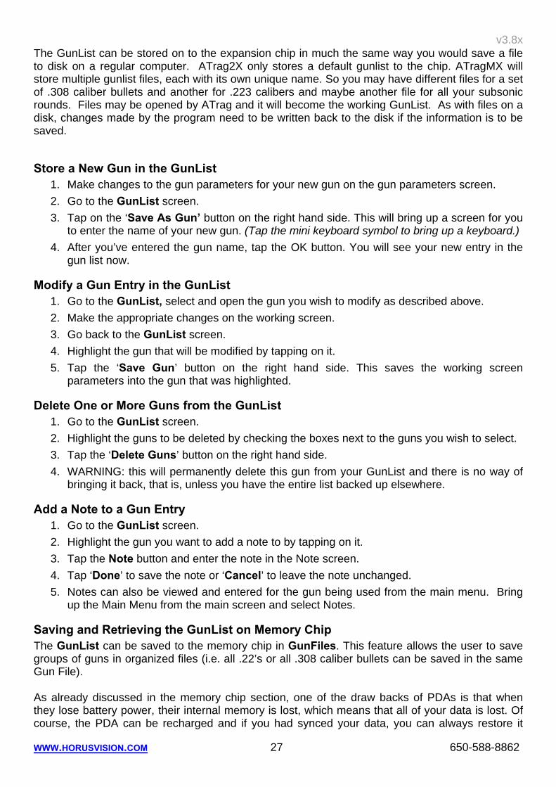
You must select a gun in order to perform an action on it. Select a Gun by checking the box in front of the gun name. Once selected, tap the Open Gun button on the right. Opening a Gun will immediately bring that Gun’s parameters into the main screen and a new shooting solution will be calculated using the new Gun’s parameters. Keep in mind that cycling through (opening) a Gun in your GunList only loads that Gun’s parameters into the main screen. Changing parameters on the main screen DOES NOT change the parameters of the Gun in the GunList. The main screen and the GunList are separate. In order to store changes from the main screen into the GunList, you must go back to the GunList screen and use the
Save or SaveAs buttons on the right hand side as described in the sections below.
Selecting Multiple Guns For some functions, you may select more than one gun to perform an action on. Simply check or uncheck desired guns.
Where is My Data Stored? Why Did My Changes Disappear? This is a good time to talk about how PDAs store and use program information. There are three (3) distinct levels of information usage and storage that you need to keep in mind as you use ATrag: the scratchpad or current working information, the GunList in the PDA’s memory, and permanent storage on the chip. In ATrag1X, where there is no GunList, it is pretty much a case of WYSIWYG or what-you-see-is-what-you-get. The information on the main screen is the sum total of all the information the program has to deal with. When you turn the program off and return later, the program remembers where you left off and all the information that was there before are retained. This retention is done in the PDA’s static memory and is prone to loss if the PDA completely losses power. On the 2X and MX, it is best to view your information from the GunList point of view. Remember that the GunList is just a collection of sets of data, and that each set represents a real gun and ammo combination. For simplicity, let’s consider a GunList consisting of 3 sets: 1) 223BlkHills, 2) 300Win, and 3) 50BMG. These three Guns reside in the GunList and the 300Win is fetched into working memory. Now the top left of the main screen shows the Gun’s name “300Win” and the 300Win’s data is loaded into working memory as can be seen on the main screen. The firing solution will therefore show what the elevation and windage for the 300Win as it relates to the Atmospheric and Target data also in working memory. What you see on the main screen is basically the working memory. If you go in to the Gun Input Screen and changed some values like the C1 coefficient and the muzzle velocity, this will change the main screen’s information and thus the firing solution. However, this change did not affect the set of information in the GunList for the 300Win. To modify the contents of the GunList, you will have to actually save it to the GunList either by modifying the entry in the GunList using “Save As Gun” which replaces the selected GunList entry with what is currently in working memory, or by saving the parameters in working memory as a new entry in the GunList with a new Gun Name – this action would increase the number of sets in the GunList to 4.
v3.8x
WWW.HORUSVISION.COM 27 650-588-8862
The GunList can be stored on to the expansion chip in much the same way you would save a file to disk on a regular computer. ATrag2X only stores a default gunlist to the chip. ATragMX will store multiple gunlist files, each with its own unique name. So you may have different files for a set of .308 caliber bullets and another for .223 calibers and maybe another file for all your subsonic rounds. Files may be opened by ATrag and it will become the working GunList. As with files on a disk, changes made by the program need to be written back to the disk if the information is to be saved.
Store a New Gun in the GunList 1. Make changes to the gun parameters for your new gun on the gun parameters screen. 2. Go to the GunList screen. 3. Tap on the ‘Save As Gun’ button on the right hand side. This will bring up a screen for you
to enter the name of your new gun. (Tap the mini keyboard symbol to bring up a keyboard.) 4. After you’ve entered the gun name, tap the OK button. You will see your new entry in the
gun list now.
Modify a Gun Entry in the GunList 1. Go to the GunList, select and open the gun you wish to modify as described above. 2. Make the appropriate changes on the working screen. 3. Go back to the GunList screen. 4. Highlight the gun that will be modified by tapping on it. 5. Tap the ‘Save Gun’ button on the right hand side. This saves the working screen
parameters into the gun that was highlighted.
Delete One or More Guns from the GunList 1. Go to the GunList screen. 2. Highlight the guns to be deleted by checking the boxes next to the guns you wish to select. 3. Tap the ‘Delete Guns’ button on the right hand side. 4. WARNING: this will permanently delete this gun from your GunList and there is no way of
bringing it back, that is, unless you have the entire list backed up elsewhere.
Add a Note to a Gun Entry 1. Go to the GunList screen. 2. Highlight the gun you want to add a note to by tapping on it. 3. Tap the Note button and enter the note in the Note screen. 4. Tap ‘Done’ to save the note or ‘Cancel’ to leave the note unchanged. 5. Notes can also be viewed and entered for the gun being used from the main menu. Bring
up the Main Menu from the main screen and select Notes.
Saving and Retrieving the GunList on Memory Chip The GunList can be saved to the memory chip in GunFiles. This feature allows the user to save groups of guns in organized files (i.e. all .22’s or all .308 caliber bullets can be saved in the same Gun File). As already discussed in the memory chip section, one of the draw backs of PDAs is that when they lose battery power, their internal memory is lost, which means that all of your data is lost. Of course, the PDA can be recharged and if you had synced your data, you can always restore it
v3.8x
WWW.HORUSVISION.COM 28 650-588-8862
from your computer. However, if you are in the field, or if you wish to carry your data around with you without a PDA, there are no good solutions for this. ATrag 2X and MX overcome this by allowing you to store your GunList to the memory chip in GunFiles (2X only allows a default file). Saving gun data in files on the same memory chip as the program allows the user to carry his gun data around no matter which PDA he is using. To prevent loss of GunList data, GunFiles can be backed up by copying the files from the chip to a PC can.
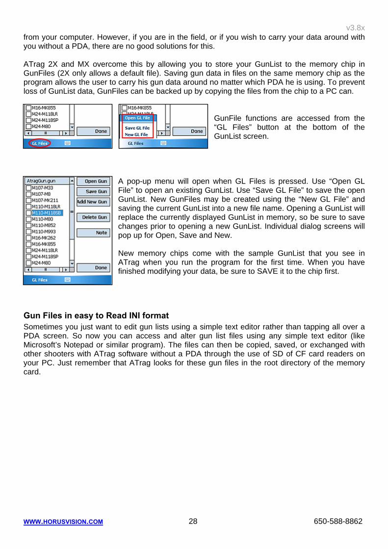
GunFile functions are accessed from the “GL Files” button at the bottom of the GunList screen.
A pop-up menu will open when GL Files is pressed. Use “Open GL File” to open an existing GunList. Use “Save GL File” to save the open GunList. New GunFiles may be created using the “New GL File” and saving the current GunList into a new file name. Opening a GunList will replace the currently displayed GunList in memory, so be sure to save changes prior to opening a new GunList. Individual dialog screens will pop up for Open, Save and New. New memory chips come with the sample GunList that you see in ATrag when you run the program for the first time. When you have finished modifying your data, be sure to SAVE it to the chip first.
Gun Files in easy to Read INI format Sometimes you just want to edit gun lists using a simple text editor rather than tapping all over a PDA screen. So now you can access and alter gun list files using any simple text editor (like Microsoft’s Notepad or similar program). The files can then be copied, saved, or exchanged with other shooters with ATrag software without a PDA through the use of SD of CF card readers on your PC. Just remember that ATrag looks for these gun files in the root directory of the memory card.
v3.8x
WWW.HORUSVISION.COM 29 650-588-8862
11. CORIOLIS / MAGNUS AND SPIN DRIFT In extreme distance shooting (1200 yards plus), the time of flight of the bullet through the air can be long enough for the Earth’s rotation (Coriolis) to ‘move’ your target from the position it was in when you pulled the trigger – causing you to miss by a yard or more. Similarly at that range, the bullets own rotation around its longitudinal axes can also ‘pull’ the bullet out of it’s aimed flight path (spin drift). Much the same way that a curve ball behaves, except that the movement is in an increasing spiral pattern. ATragMX version compensates for these deviations.
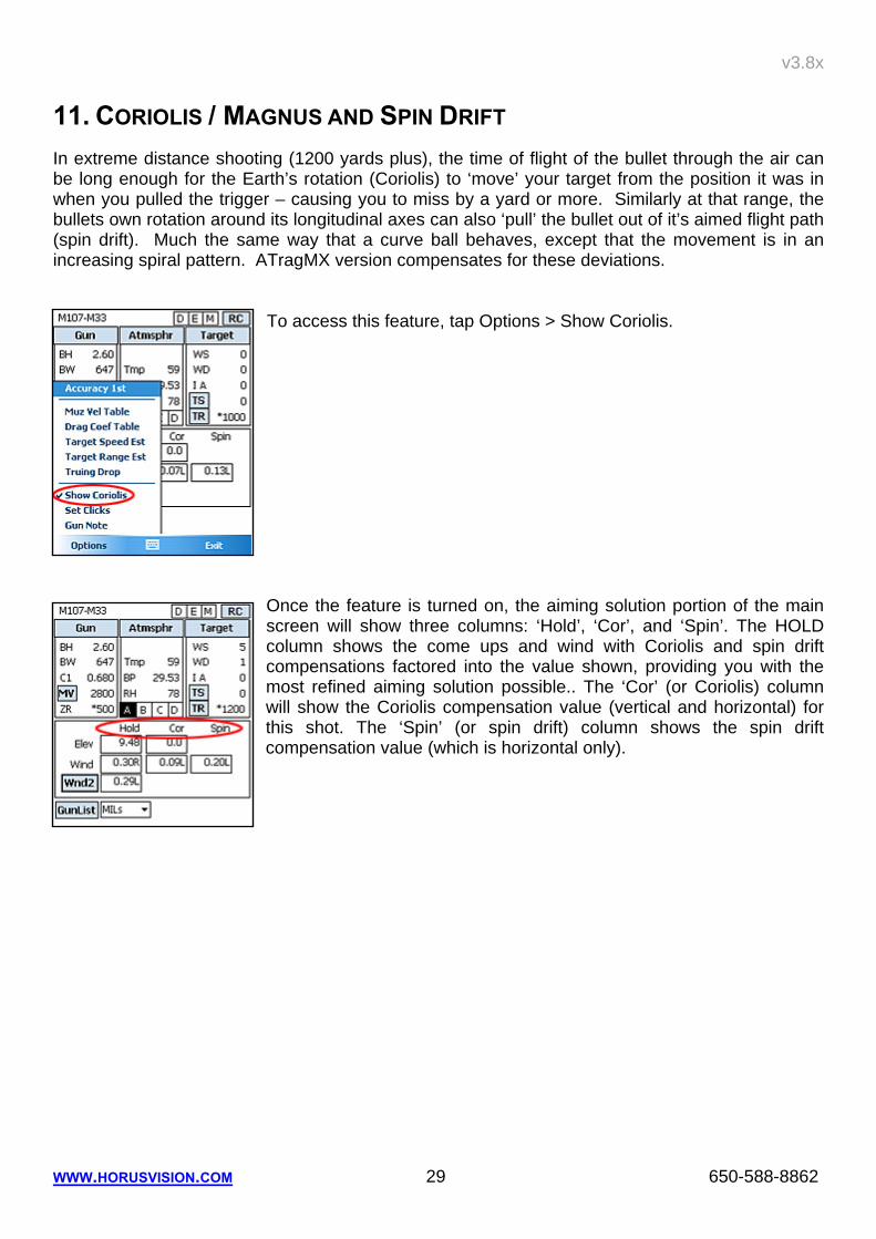
To access this feature, tap Options > Show Coriolis.
Once the feature is turned on, the aiming solution portion of the main screen will show three columns: ‘Hold’, ‘Cor’, and ‘Spin’. The HOLD column shows the come ups and wind with Coriolis and spin drift compensations factored into the value shown, providing you with the most refined aiming solution possible.. The ‘Cor’ (or Coriolis) column will show the Coriolis compensation value (vertical and horizontal) for this shot. The ‘Spin’ (or spin drift) column shows the spin drift compensation value (which is horizontal only).
v3.8x
WWW.HORUSVISION.COM 30 650-588-8862
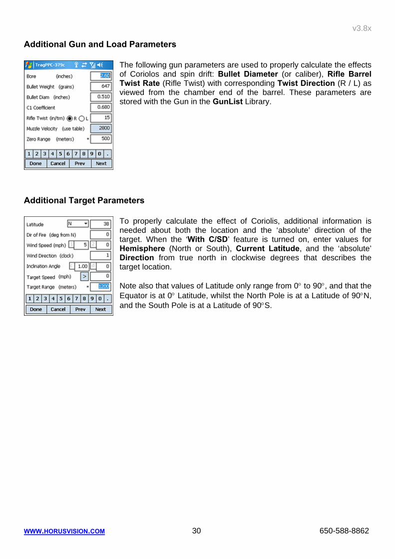
Additional Gun and Load Parameters
The following gun parameters are used to properly calculate the effects of Coriolos and spin drift: Bullet Diameter (or caliber), Rifle Barrel Twist Rate (Rifle Twist) with corresponding Twist Direction (R / L) as viewed from the chamber end of the barrel. These parameters are stored with the Gun in the GunList Library.
Additional Target Parameters To properly calculate the effect of Coriolis, additional information is needed about both the location and the ‘absolute’ direction of the target. When the ‘With C/SD’ feature is turned on, enter values for Hemisphere (North or South), Current Latitude, and the ‘absolute’ Direction from true north in clockwise degrees that describes the target location. Note also that values of Latitude only range from 0° to 90°, and that the Equator is at 0° Latitude, whilst the North Pole is at a Latitude of 90°N, and the South Pole is at a Latitude of 90°S.
v3.8x
WWW.HORUSVISION.COM 31 650-588-8862
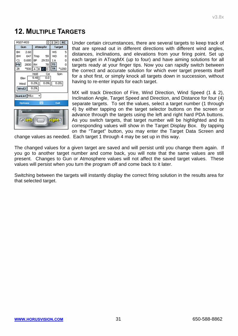
12. MULTIPLE TARGETS Under certain circumstances, there are several targets to keep track of that are spread out in different directions with different wind angles, distances, inclinations, and elevations from your firing point. Set up each target in ATragMX (up to four) and have aiming solutions for all targets ready at your finger tips. Now you can rapidly switch between the correct and accurate solution for which ever target presents itself for a shot first, or simply knock all targets down in succession, without having to re-enter inputs for each target. MX will track Direction of Fire, Wind Direction, Wind Speed (1 & 2), Inclination Angle, Target Speed and Direction, and Distance for four (4) separate targets. To set the values, select a target number (1 through 4) by either tapping on the target selector buttons on the screen or advance through the targets using the left and right hard PDA buttons. As you switch targets, that target number will be highlighted and its corresponding values will show in the Target Display Box. By tapping on the “Target” button, you may enter the Target Data Screen and
change values as needed. Each target 1 through 4 may be set up in this way. The changed values for a given target are saved and will persist until you change them again. If you go to another target number and come back, you will note that the same values are still present. Changes to Gun or Atmosphere values will not affect the saved target values. These values will persist when you turn the program off and come back to it later. Switching between the targets will instantly display the correct firing solution in the results area for that selected target.
v3.8x
WWW.HORUSVISION.COM 32 650-588-8862
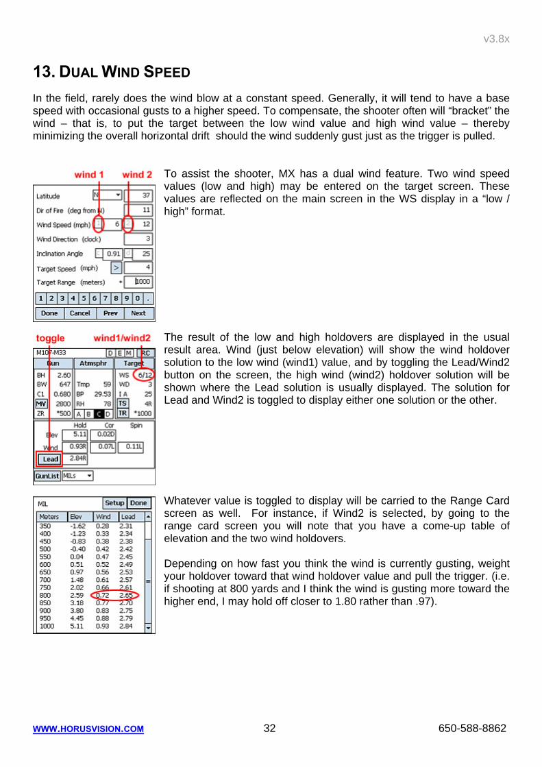
13. DUAL WIND SPEED In the field, rarely does the wind blow at a constant speed. Generally, it will tend to have a base speed with occasional gusts to a higher speed. To compensate, the shooter often will “bracket” the wind – that is, to put the target between the low wind value and high wind value – thereby minimizing the overall horizontal drift should the wind suddenly gust just as the trigger is pulled.
To assist the shooter, MX has a dual wind feature. Two wind speed values (low and high) may be entered on the target screen. These values are reflected on the main screen in the WS display in a “low / high” format. The result of the low and high holdovers are displayed in the usual result area. Wind (just below elevation) will show the wind holdover solution to the low wind (wind1) value, and by toggling the Lead/Wind2 button on the screen, the high wind (wind2) holdover solution will be shown where the Lead solution is usually displayed. The solution for Lead and Wind2 is toggled to display either one solution or the other. Whatever value is toggled to display will be carried to the Range Card screen as well. For instance, if Wind2 is selected, by going to the range card screen you will note that you have a come-up table of elevation and the two wind holdovers. Depending on how fast you think the wind is currently gusting, weight your holdover toward that wind holdover value and pull the trigger. (i.e. if shooting at 800 yards and I think the wind is gusting more toward the higher end, I may hold off closer to 1.80 rather than .97).
v3.8x
WWW.HORUSVISION.COM 33 650-588-8862
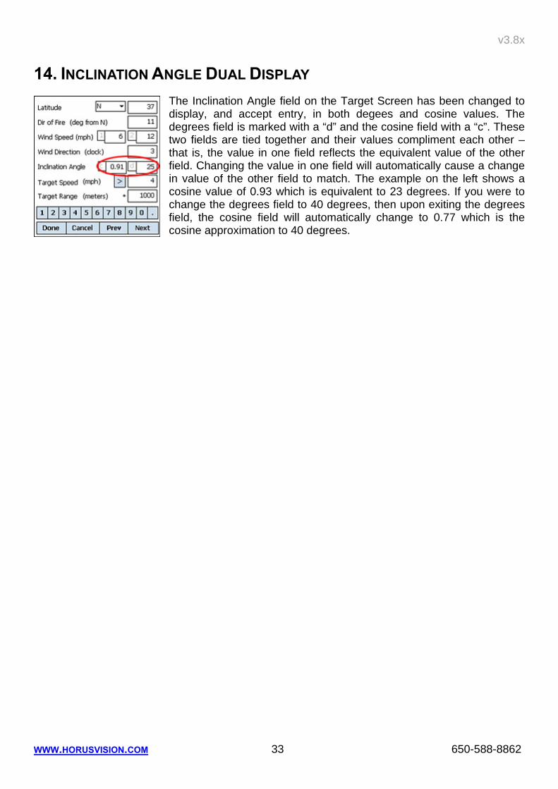
14. INCLINATION ANGLE DUAL DISPLAY The Inclination Angle field on the Target Screen has been changed to display, and accept entry, in both degees and cosine values. The degrees field is marked with a “d” and the cosine field with a “c”. These two fields are tied together and their values compliment each other – that is, the value in one field reflects the equivalent value of the other field. Changing the value in one field will automatically cause a change in value of the other field to match. The example on the left shows a cosine value of 0.93 which is equivalent to 23 degrees. If you were to change the degrees field to 40 degrees, then upon exiting the degrees field, the cosine field will automatically change to 0.77 which is the cosine approximation to 40 degrees.
v3.8x
WWW.HORUSVISION.COM 34 650-588-8862
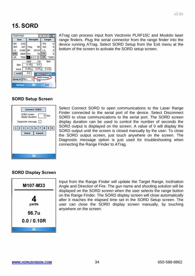
15. SORD ATrag can process input from Vectronix PLRF15C and Moskito laser range finders. Plug the serial connector from the range finder into the device running ATrag. Select SORD Setup from the Exit menu at the bottom of the screen to activate the SORD setup screen.
SORD Setup Screen
Select Connect SORD to open communications to the Laser Range Finder connected to the serial port of the device. Select Disconnect SORD to close communications to the serial port. The SORD screen display duration can be used to control the number of seconds the SORD output is displayed on the screen. A value of 0 will display the SORD output until the screen is closed manually by the user. To close the SORD output screen, just touch anywhere on the screen. The Diagnostic message option is just used for troubleshooting when connecting the Range Finder to ATrag.
SORD Display Screen
Input from the Range Finder will update the Target Range, Inclination Angle and Direction of Fire. The gun name and shooting solution will be displayed on the SORD screen when the user selects the range button on the Range Finder. The SORD display screen will close automatically after it reaches the elapsed time set in the SORD Setup screen. The user can close the SORD display screen manually, by touching anywhere on the screen.
v3.8x
WWW.HORUSVISION.COM 35 650-588-8862
16. COMING SOON Thought we’d give you a sneak preview of upcoming features.
Moon Phase, Sun/Moon Rise/Set Times Available light conditions are crucial for stalking and shooting. Knowing how much daylight and moon light there will be can make the difference between success and failure. Knowing the time, date and location, ATrag will be able to provide a portable almanac of celestial information anywhere in the world.
ATrag for Second Plane Scopes If you own a second Plane scope, ATrag will be able to handle it. Why not? The relationships between zoom magnification and distance are well known and easily (for a computer) to calculate.
Common Object Size Library Your target is in your sites, but in such a way that you cannot get a good reference on its size, making ranging difficult. But wait, the target is right next to an old VW minibus. A couple of taps later, ATrag tells you that the minibus is 62 inches tall. You plug this into the range estimator, telling ATrag that it measures 2.3 mils in the scope, et voila, you have the range to target. We have located a library of sizes for thousands of common objects – including many not so common objects such as the lengths of all known foreign rifles. With this library, you should never be at a loss for objects to range by.
v3.8x
WWW.HORUSVISION.COM 36 650-588-8862
17. APPENDIX A – MUZZLE VELOCITY AND BALLISTIC COEFFICIENT’S Historic Overview All the problems with Muzzle Velocity and Ballistic Coefficient’s have existed for the last 100 years. Riflemen used a “guesstimation” method and titrated their data with records kept in data books. For generations, optics that featured mil-dot/clicking scopes were mass produced sometimes little attention was given to calibration of the reticle and elevation and windage adjustments. To further complicate matters, the vast majority of these scopes were in the second focal plane. When the Horus system made its appearance, the rifleman realized a vast improvement in the ability to engage targets at any range. For the first time the rifleman had an accurate highly calibrated reticle combined with software designed specifically for aiming/targeting. Riflemen began to realize the problems with published Muzzle Velocity and Ballistic Coefficient’s values. To shoot accurately you, the rifleman, must have accurate reliable data for Muzzle Velocity and Ballistic Coefficient’s. Muzzle Velocity
Horus Vision’s ATrag 2X & MX software allows for entry of seven different temperatures with their respective M.V. to obtain accurate, repeatable results. When engaging long range targets, you should make an effort to enter accurate chronographic data that reflects M.V. over the full range of temperatures that you expect to encounter in your area of operation. One or two points of chronographing will not yield accurate results over a large temperature range. As the range limits of extended range shooting are expanded by knowledgeable riflemen, the need for accurate and reliable data for M.V. and B.C. is absolutely paramount for Horus Vision software to yield accurate, repeatable aiming point data. Accurate data in combination with the Horus riflescope and ATrag software will give the rifleman a tactical, lethal advantage at extended ranges. Horus ATrag software have 3 areas of data entry:
a. Gun b. Atmosphere c. Target
I focused on the area of “gun” info because it addresses M.V. and B.C. Inaccurate data in either of these categories can lead to inaccurate shot placement. Worse yet, as your target range increases your inability to hit the target increases exponentially. Muzzle Velocity is a prime culprit of error. A single M.V. figure taken from a manual or box of ammo is usually based on a 24” barrel length under standard meteorological conditions. The manufacturers M.V. figures should only be used as a starting point. In the real world you will be engaging in targets in variable temperature conditions. M.V. increases or decreases with respect to temperature. Unfortunately, gun powder does not burn at a constant rate regardless of temperature changes. The colder the temperature, the slower the powder burns yielding a reduced or slower M.V. The hotter the temperature, the faster it burns yielding an increased M.V.
v3.8x
WWW.HORUSVISION.COM 37 650-588-8862
All gun powders react differently to temperature changes. I have personally chronographed some cartridges that remained at one M.V. + 5 ft./sec over a range of 19˚ F. However, once I exceeded an upper limit, the M.V. jumped 23 ft./sec with a 1˚ change. The powder that yields a perfect linear relationship for temperature and M.V. does not exist. That is the reason the long range rifleman must take chronographic data from the broad spectrum of temperatures he will encounter. For obtaining the most accurate data for M.V., do the following:
1. Select a rifle in excellent condition. If there is any question, have it checked by a competent gunsmith.
2. Use only one rifle. Your barrel length will then be a constant. 3. Select the ammo of your choice. Use all ammo from the same lot. 4. Use a high quality chronograph (i.e. Ohler 35P) 5. You must chronograph cartridges over a large temperature range. 6. Before each chronograph set, be sure the rifle and ammo are at the same temperature
(Raytech infrared instrument is a good measurement device). 7. To obtain a temperature spread in a single day, shoot at various times of the day.
a. early morning b. mid-day c. late afternoon d. evening
8. Personally, I find chronographing at a specific outside temperature of say 10˚ F difficult to accomplish especially if I am doing my work in the summer. Therefore, I use a modified method to obtain muzzle velocity data.
a. I put my rifle and ammo in my home freezer. I place a thermometer next to the rifle and ammo. Ammo must be at same temperature as rifle.
b. I wrap the gun and ammo in several heavy blankets and let it freeze for at least 24 hours. I set the freezer temperature control 5 to 10 degrees colder than my decided testing temperature.
c. Going to the range, I leave the rifle and ammo wrapped. I always take an extra gun to test the chronograph to insure it is working properly.
d. When ready, I unwrap the rifle and ammo. If I have done everything correctly, the rifle and ammo is still frozen and the thermometer should read 10˚ F.
e. I fire three to four shots and use that average. When employing the modified method for warm to hot temperature, I use hot water bottles and towels. I wrap the gun and ammo up until I reach the desired temperature, then I do my chronographing. Ballistic Coefficient’s: B.C.’s are also capable of producing errors. Figures for B.C. are usually found in manuals, brochures or books. They are seldom, if ever, found on the box of ammo/cartridges. B.C.’s are usually calculated by the manufacturer of the bullets. There is no central agency to validate given B.C. values.
v3.8x
WWW.HORUSVISION.COM 38 650-588-8862
It should be noted that some bullet manufacturer do an excellent job in calculating B.C. values. Others use the “guesstimation” method based on size and shape alone. A few probably inflate B.C. values to make their bullets look better. (Please read the article on Ballistic Coefficient by Bill Davis on the HorusVision website.) With the Horus system, the rifleman must have an absolutely accurate B.C. figure to reliably engage at long range. How do you determine if your B.C. value for your bullet/cartridge needs adjusting? Enter your newly calculated M.V. number along with the current weather conditions. Select a target at 400-600 yards that you have very accurately measured the distance from muzzle to target. Use your hand held PDA with ATrag to calculate the exact come up (the line to hold on using the Horus scope/reticle). Fire 3 or more shots. If you hit the target your B.C. value is O.K. You are finished. In the event your bullets grouped high or low, you must adjust your B.C. value (example: your starting B.C. is .640 try .660 and so on). If the group was low, try lower B.C. value (example: your starting B.C. is .640 try .590 and so on). Go back to your PDA and try different B.C. values until you find one that exactly corresponds to the live fire come up. Example 1: Having accurately entered all data into the ATrag and then zeroed your rifle at, for example, 100 yards, you notice that upon firing at progressively increasing ranges, the bullet’s point of impact (POI) is increasingly falling below the point of aim (POA). With all other data entry operations having been performed correctly, it is quite evident that the manufacturer’s specified BC has, in fact, been over stated! Remedy: With your rifle already zeroed at 100 yards, you use the ATrag calculator to give your aiming solution for a 400 yard target face, then fire a group (or indeed, just a single shot), and whilst maintaining the original 400 yard aiming solution sight picture, make a written (or mental) note of the actual Horus coordinates of the group's mean POI. Now go back into 'Gun' and stepwise reduce (or increase if BC is too low, ie, POI is high) the input BC until the Horus reading generated for the 400 yard target, becomes the actual Horus coordinates recorded for the group's mean POI at 400 yards. Example 2: For any number of reasons, you're out in the field, ready to party on, except there's no BC! Remedy: Having accurately entered all other data into the ATrag, and then zeroed your rifle at, for example, 100 yards, simply maintain the 100 yard Horus sight picture (ie, using the main cross-hair), but now lay it on a POA at, for example 400 yards. Fire a single shot (or group if necessary), and record the mean fall of shot below the 400 yard POA. ATrag will then provide a dialog box which prompts the shooter to enter this mean fall of shot (E or M) below the 400 yard POA, whereupon ATrag will immediately generate the real, dynamic BC for that projectile, over that flight range.
v3.8x
WWW.HORUSVISION.COM 39 650-588-8862
18. APPENDIX B – ADDITIONAL NOTES FOR NOMAD AND RECON PDAS
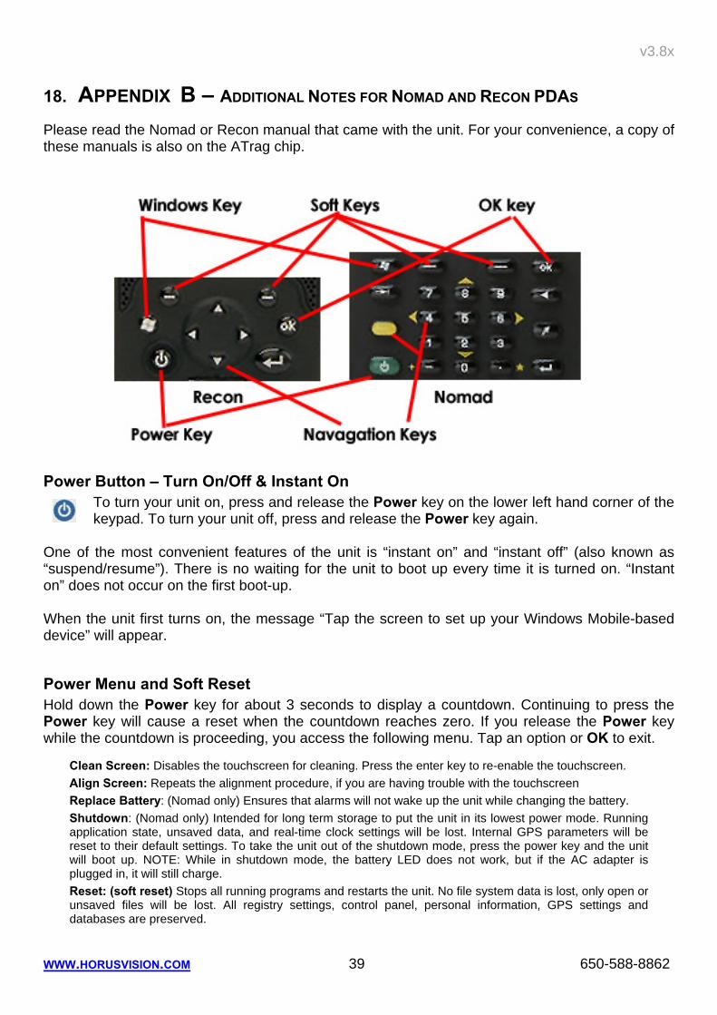
Please read the Nomad or Recon manual that came with the unit. For your convenience, a copy of these manuals is also on the ATrag chip.
Power Button – Turn On/Off & Instant On To turn your unit on, press and release the Power key on the lower left hand corner of the keypad. To turn your unit off, press and release the Power key again.
One of the most convenient features of the unit is “instant on” and “instant off” (also known as “suspend/resume”). There is no waiting for the unit to boot up every time it is turned on. “Instant on” does not occur on the first boot-up. When the unit first turns on, the message “Tap the screen to set up your Windows Mobile-based device” will appear.
Power Menu and Soft Reset Hold down the Power key for about 3 seconds to display a countdown. Continuing to press the Power key will cause a reset when the countdown reaches zero. If you release the Power key while the countdown is proceeding, you access the following menu. Tap an option or OK to exit.
Clean Screen: Disables the touchscreen for cleaning. Press the enter key to re-enable the touchscreen. Align Screen: Repeats the alignment procedure, if you are having trouble with the touchscreen Replace Battery: (Nomad only) Ensures that alarms will not wake up the unit while changing the battery. Shutdown: (Nomad only) Intended for long term storage to put the unit in its lowest power mode. Running application state, unsaved data, and real-time clock settings will be lost. Internal GPS parameters will be reset to their default settings. To take the unit out of the shutdown mode, press the power key and the unit will boot up. NOTE: While in shutdown mode, the battery LED does not work, but if the AC adapter is plugged in, it will still charge. Reset: (soft reset) Stops all running programs and restarts the unit. No file system data is lost, only open or unsaved files will be lost. All registry settings, control panel, personal information, GPS settings and databases are preserved.
v3.8x
WWW.HORUSVISION.COM 40 650-588-8862
Clean Boot or Hard Reset
[ WARNING: All application software, (installed by the factory and the customer) licenses, settings and user data will be cleared if you perform this function! All data and programs stored on the SD or CF chip, however, should stay intact. ]
On Nomad: To perform a clean boot – or Hard Reset – hold down the Power key and press the right soft key to display a countdown. Continue to hold down both keys until it counts down to zero, followed by a brief appearance of the boot screen. Continue to hold both keys down until a screen appears warning that if you continue, this operation will clear the persistent store. Follow the instructions on the screen ONLY if you want to completely clear your unit. On Recon: Hold down the Power key to display a countdown. Continue to hold down the Power key until it counts down to zero and beeps twice. Then immediately hold down the Start and OK keys simultaneously. After a few seconds, a screen will come up warning that if you continue, this operation will clear the persistent store including all user data, applications and settings. Follow the instructions on the screen ONLY if you want to completely clear your unit
Windows and OK Buttons Just like on a regular desktop or laptop running windows, this button will pop up the Start Menu. Programs can be launched as new windows and will hide the windows below it. The OK button closes the top most window. It acts on any window that has an “X” button or “ok” button in its top right corner.
Soft Buttons The Soft Buttons may be set to launch any installed program on the PDA. This is usually done through the System Settings screen. Press Start, select Settings, tap on the Buttons icon. Recons and Nomads come from Horus with the left soft button set to launch File Explorer and the right soft button to launch ATrag.
Navigation Buttons The navigation buttons on the Recon works pretty much the same way as all the 5-way buttons on any PDA. The Nomad requires that you hold down the yellow function key and simultaneously press the 2, 4, 6 and 8 keys to work the same way as the down, left, right and up buttons of a 5-way arrangement.
v3.8x
WWW.HORUSVISION.COM
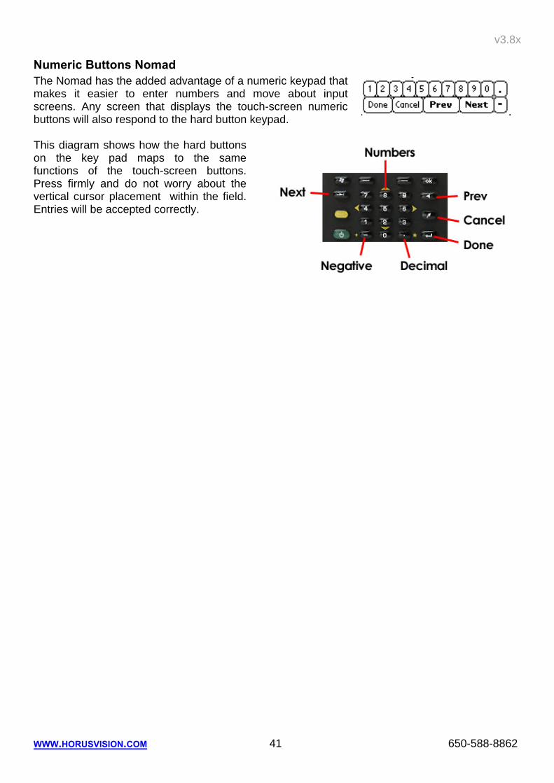
Numeric Buttons Nomad The Nomad has the added advantage of a numeric keypad that makes it easier to enter numbers and move about input screens. Any screen that displays the touch-screen numeric buttons will also respond to the hard button keypad. This diagram shows how the hard buttons on the key pad maps to the same functions of the touch-screen buttons. Press firmly and do not worry about the vertical cursor placement within the field. Entries will be accepted correctly.
41 650-588-8862