Embed Size (px)
Citation preview
www.schneider-electric.comMN
A01
M00
1EN
, V1.
00, 1
2.20
10
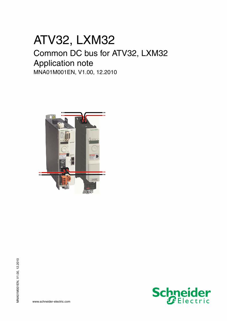
ATV32, LXM32Common DC bus for ATV32, LXM32Application noteMNA01M001EN, V1.00, 12.2010
2 Common DC bus for ATV32, LXM32
Important information ATV32, LXM32
MN
A01
M00
1EN
, V1.
00, 1
2.20
10
Important information
This document is part of the product.
Carefully read this document and observe all instructions.
Keep this document for future reference.
Hand this document and all other pertinent product documentation over to all users of the product.
Carefully read and observe all safety instructions and the chapter "Be-fore you begin - safety information".
Some products are not available in all countries.Please consult the latest catalog for information on the availability of products.
Subject to technical modifications without notice.
All details provided are technical data which do not constitute warranted qualities.
Most of the product designations are registered trademarks of their re-spective owners, even if this is not explicitly indicated.
MN
A01
M00
1EN
, V1.
00, 1
2.20
10
ATV32, LXM32 Table of contents
Common DC bus for ATV32, LXM32 3
Table of contents
Important information. . . . . . . . . . . . . . . . . . . . . . . . . . . . . . . . . 2
Table of contents . . . . . . . . . . . . . . . . . . . . . . . . . . . . . . . . . . . . 3
About this manual. . . . . . . . . . . . . . . . . . . . . . . . . . . . . . . . . . . . 5
1 Introduction . . . . . . . . . . . . . . . . . . . . . . . . . . . . . . . . . . . . . . . . . 7
2 Before you begin - safety information. . . . . . . . . . . . . . . . . . . . 9
2.1 Qualification of personnel . . . . . . . . . . . . . . . . . . . . . . . . 9
2.2 Intended use . . . . . . . . . . . . . . . . . . . . . . . . . . . . . . . . . . 9
2.3 Hazard categories . . . . . . . . . . . . . . . . . . . . . . . . . . . . . 10
2.4 Basic information. . . . . . . . . . . . . . . . . . . . . . . . . . . . . . 11
2.5 DC bus voltage measurement . . . . . . . . . . . . . . . . . . . . 13
2.6 Standards and terminology . . . . . . . . . . . . . . . . . . . . . . 13
3 Technical Data . . . . . . . . . . . . . . . . . . . . . . . . . . . . . . . . . . . . . . 15
3.1 Firmware version. . . . . . . . . . . . . . . . . . . . . . . . . . . . . . 15
3.2 Drive data . . . . . . . . . . . . . . . . . . . . . . . . . . . . . . . . . . . 153.2.1 Permissible device types for common DC bus . . . . . 153.2.2 ATV32: DC bus data . . . . . . . . . . . . . . . . . . . . . . . . . 163.2.3 LXM32: DC bus data . . . . . . . . . . . . . . . . . . . . . . . . 21
3.3 Fuses. . . . . . . . . . . . . . . . . . . . . . . . . . . . . . . . . . . . . . . 243.3.1 Mains fuse . . . . . . . . . . . . . . . . . . . . . . . . . . . . . . . . 243.3.2 Fuse for DC bus . . . . . . . . . . . . . . . . . . . . . . . . . . . . 24
3.4 Cables for DC bus . . . . . . . . . . . . . . . . . . . . . . . . . . . . . 26
3.5 Braking resistor . . . . . . . . . . . . . . . . . . . . . . . . . . . . . . . 273.5.1 External braking resistors (accessories). . . . . . . . . . 27
3.6 Mains filter . . . . . . . . . . . . . . . . . . . . . . . . . . . . . . . . . . . 28
3.7 Mains reactors. . . . . . . . . . . . . . . . . . . . . . . . . . . . . . . . 28
4 Engineering . . . . . . . . . . . . . . . . . . . . . . . . . . . . . . . . . . . . . . . . 29
4.1 EMC specifics . . . . . . . . . . . . . . . . . . . . . . . . . . . . . . . . 29
4.2 Mounting distances . . . . . . . . . . . . . . . . . . . . . . . . . . . . 30
4.3 Energy balance . . . . . . . . . . . . . . . . . . . . . . . . . . . . . . . 304.3.1 Energy absorption . . . . . . . . . . . . . . . . . . . . . . . . . . 31
4.4 Prerequisites for a common DC bus . . . . . . . . . . . . . . . 33
4 Common DC bus for ATV32, LXM32
Table of contents ATV32, LXM32
MN
A01
M00
1EN
, V1.
00, 1
2.20
10
4.5 Structure of a common DC bus . . . . . . . . . . . . . . . . . . 344.5.1 Common mains fuses . . . . . . . . . . . . . . . . . . . . . . . 344.5.2 Separate mains fuses . . . . . . . . . . . . . . . . . . . . . . . 364.5.3 DC supply via a drive . . . . . . . . . . . . . . . . . . . . . . . . 384.5.4 DC supply via DC power supply unit . . . . . . . . . . . . 41
4.6 Accessories for the common DC bus . . . . . . . . . . . . . . 434.6.1 Braking resistors . . . . . . . . . . . . . . . . . . . . . . . . . . . 434.6.2 Mains reactor . . . . . . . . . . . . . . . . . . . . . . . . . . . . . . 484.6.3 External mains filter . . . . . . . . . . . . . . . . . . . . . . . . . 504.6.4 Mains reactor and external mains filter . . . . . . . . . . 514.6.5 Cables for DC bus . . . . . . . . . . . . . . . . . . . . . . . . . . 51
5 Installation. . . . . . . . . . . . . . . . . . . . . . . . . . . . . . . . . . . . . . . . . . 53
5.1 Cables for DC bus . . . . . . . . . . . . . . . . . . . . . . . . . . . . 54
5.2 Wiring the DC bus . . . . . . . . . . . . . . . . . . . . . . . . . . . . 565.2.1 Connecting the DC bus . . . . . . . . . . . . . . . . . . . . . . 58
5.3 Checking installation. . . . . . . . . . . . . . . . . . . . . . . . . . . 59
6 Commissioning. . . . . . . . . . . . . . . . . . . . . . . . . . . . . . . . . . . . . . 61
6.1 Commissioning procedure . . . . . . . . . . . . . . . . . . . . . . 62
6.2 LXM32: Setting the braking resistor parameters . . . . . 63
7 Accessories and spare parts . . . . . . . . . . . . . . . . . . . . . . . . . . 65
7.1 DC bus accessories . . . . . . . . . . . . . . . . . . . . . . . . . . . 65
7.2 DC fuses. . . . . . . . . . . . . . . . . . . . . . . . . . . . . . . . . . . . 65
7.3 External braking resistors . . . . . . . . . . . . . . . . . . . . . . . 66
8 Glossary . . . . . . . . . . . . . . . . . . . . . . . . . . . . . . . . . . . . . . . . . . . 67
8.1 Units and conversion tables . . . . . . . . . . . . . . . . . . . . . 678.1.1 Length . . . . . . . . . . . . . . . . . . . . . . . . . . . . . . . . . . . 678.1.2 Mass . . . . . . . . . . . . . . . . . . . . . . . . . . . . . . . . . . . . 678.1.3 Force . . . . . . . . . . . . . . . . . . . . . . . . . . . . . . . . . . . . 678.1.4 Power . . . . . . . . . . . . . . . . . . . . . . . . . . . . . . . . . . . . 678.1.5 Rotation . . . . . . . . . . . . . . . . . . . . . . . . . . . . . . . . . . 688.1.6 Torque . . . . . . . . . . . . . . . . . . . . . . . . . . . . . . . . . . . 688.1.7 Moment of inertia . . . . . . . . . . . . . . . . . . . . . . . . . . . 688.1.8 Temperature. . . . . . . . . . . . . . . . . . . . . . . . . . . . . . . 688.1.9 Conductor cross section . . . . . . . . . . . . . . . . . . . . . 68
8.2 Terms and Abbreviations . . . . . . . . . . . . . . . . . . . . . . . 69
9 Index . . . . . . . . . . . . . . . . . . . . . . . . . . . . . . . . . . . . . . . . . . . . . . 71
MN
A01
M00
1EN
, V1.
00, 1
2.20
10
ATV32, LXM32 About this manual
Common DC bus for ATV32, LXM32 5
About this manual
This document describes how several Schneider Electric drives types ATV32 and LXM32 can share a common DC bus.This application note replaces application note MNA01D001.
The information provided in this document supplements the manuals. Before beginning, carefully read the manuals of products used.
Source manuals The latest versions of the manuals can be downloaded from the Internet at:
http://www.schneider-electric.com
Corrections and suggestions We always try to further optimize our manuals. We welcome your sug-gestions and corrections.
Please get in touch with us by e-mail:[email protected].
Work steps If work steps must be performed consecutively, this sequence of steps is represented as follows:
� Special prerequisites for the following work steps
� Step 1
� Specific response to this work step
� Step 2
If a response to a work step is indicated, this allows you to verify that the work step has been performed correctly.
Unless otherwise stated, the individual steps must be performed in the specified sequence.
Making work easier Information on making work easier is highlighted by this symbol:
Sections highlighted this way provide supplementary information on making work easier.
SI units SI units are the original values. Converted units are shown in brackets behind the original value; they may be rounded.
Example:Minimum conductor cross section: 1.5 mm2 (AWG 14)
Glossary Explanations of special technical terms and abbreviations.
Index List of keywords with references to the corresponding page numbers.
6 Common DC bus for ATV32, LXM32
About this manual ATV32, LXM32
MN
A01
M00
1EN
, V1.
00, 1
2.20
10
MN
A01
M00
1EN
, V1.
00, 1
2.20
10
ATV32, LXM32 1 Introduction
Common DC bus for ATV32, LXM32 7
11 Introduction
A drive system requires energy for acceleration or constant movement that must be supplied to the system. During deceleration, a motor acts as a generator. A considerable portion of the kinetic energy is re-gener-ated as electrical energy.
Since electrical energy can only be stored to a limited extent in a single drive, a drive uses a braking resistor to transform the excess energy into thermal energy.
Use of electrical energy If an application uses several drive systems, the regenerated energy can be used to accelerate other motors. The regenerated power can be used efficiently during anti-cyclical operation, i.e. one motor decelerates while another motor accelerates at the same time. The energy can be ex-changed when the DC buses of the drives are connected.
Drives supporting the use of acommon DC bus
The following drives can be operated via a common DC bus:
• Single-phase drives with single-phase drives
– ATV32••••M2 with ATV32••••M2
– ATV32••••M2 with LXM32••••M2
– LXM32••••M2 with LXM32••••M2
• Three-phase drives with three-phase drives
– ATV32••••N4 with ATV32••••N4
– LXM32••••N4 with LXM32••••N4
– ATV32••••N4 with LXM32••••N4
It is not permissible to operate single-phase drives in combination with three-phase drives.

8 Common DC bus for ATV32, LXM32
1 Introduction ATV32, LXM32
MN
A01
M00
1EN
, V1.
00, 1
2.20
10
MN
A01
M00
1EN
, V1.
00, 1
2.20
10
ATV32, LXM32 2 Before you begin - safety information
Common DC bus for ATV32, LXM32 9
22 Before you begin - safety information
The information provided in this document supplements the manuals. Before beginning, carefully read the manuals of products used.
2.1 Qualification of personnel
Only appropriately trained persons who are familiar with and understand the contents of this manual and all other pertinent product documenta-tion are authorized to work on and with this product. In addition, these persons must have received safety training to recognize and avoid haz-ards involved. These persons must have sufficient technical training, knowledge and experience and be able to foresee and detect potential hazards that may be caused by using the product, by changing the set-tings and by the mechanical, electrical and electronic equipment of the entire system in which the product is used.
All persons working on and with the product must be fully familiar with all applicable standards, directives, and accident prevention regulations when performing such work.
2.2 Intended use
The functions described in this document are only intended for use for the products described in this document.
The product may only be used in compliance with all applicable safety regulations and directives, the specified requirements and the technical data.
Prior to using the product, you must perform a risk assessment in view of the planned application. Based on the results, the appropriate safety measures must be implemented.
Since the product is used as a component in an entire system, you must ensure the safety of persons by means of the design of this entire sys-tem (for example, machine design).
Operate the product only with the specified cables and accessories. Use only genuine accessories and spare parts.
The product must NEVER be operated in explosive atmospheres (haz-ardous locations, Ex areas).
Any use other than the use explicitly permitted is prohibited and can re-sult in hazards.
Electrical equipment should be installed, operated, serviced, and main-tained only by qualified personnel.
10 Common DC bus for ATV32, LXM32
2 Before you begin - safety information ATV32, LXM32
MN
A01
M00
1EN
, V1.
00, 1
2.20
10
2.3 Hazard categories
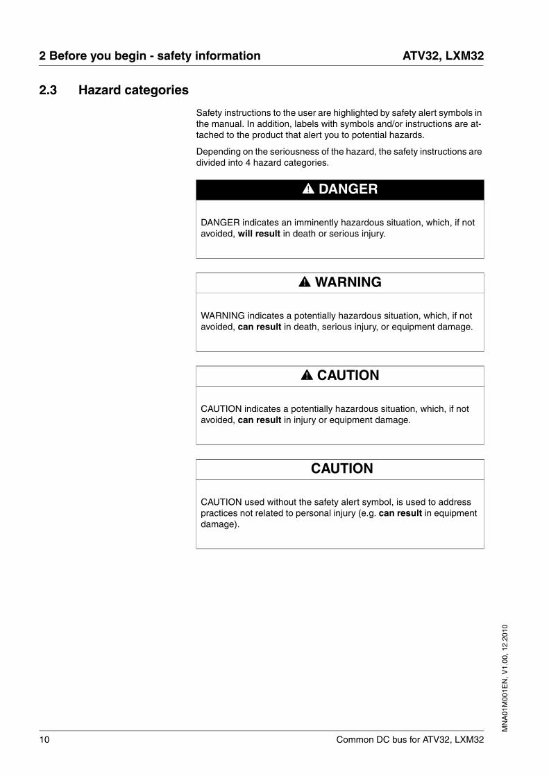
Safety instructions to the user are highlighted by safety alert symbols in the manual. In addition, labels with symbols and/or instructions are at-tached to the product that alert you to potential hazards.
Depending on the seriousness of the hazard, the safety instructions are divided into 4 hazard categories.
@ DANGER
DANGER indicates an imminently hazardous situation, which, if not avoided, will result in death or serious injury.
@ WARNING
WARNING indicates a potentially hazardous situation, which, if not avoided, can result in death, serious injury, or equipment damage.
@ CAUTION
CAUTION indicates a potentially hazardous situation, which, if not avoided, can result in injury or equipment damage.
CAUTION
CAUTION used without the safety alert symbol, is used to address practices not related to personal injury (e.g. can result in equipment damage).
MN
A01
M00
1EN
, V1.
00, 1
2.20
10
ATV32, LXM32 2 Before you begin - safety information
Common DC bus for ATV32, LXM32 11
2.4 Basic information
@ DANGERHAZARD OF ELECTRIC SHOCK, EXPLOSION OR ARC FLASH
• Only appropriately trained persons who are familiar with and understand the contents of this manual and all other pertinent product documentation and who have received safety training to recognize and avoid hazards involved are authorized to work on and with this drive system. Installation, adjustment, repair and maintenance must be performed by qualified personnel.
• The system integrator is responsible for compliance with all local and national electrical code requirements as well as all other applicable regulations with respect to grounding of all equipment.
• Many components of the product, including the printed circuit board, operate with mains voltage. Do not touch. Only use electri-cally insulated tools.
• Do not touch unshielded components or terminals with voltage present.
• The motor generates voltage when the shaft is rotated. Prior to performing any type of work on the drive system, block the motor shaft to prevent rotation.
• AC voltage can couple voltage to unused conductors in the motor cable. Insulate both ends of unused conductors in the motor cable.
• Do not short across the DC bus terminals or the DC bus capaci-tors.
• Before performing work on the drive system:
– Disconnect all power, including external control power that may be present.
– Place a "DO NOT TURN ON" label on all power switches.
– Lock all power switches in the open position.
– Wait 15 minutes to allow the DC bus capacitors to discharge. Measure the voltage on the DC bus as per chapter "DC bus voltage measurement" and verify the voltage is < 42 Vdc. The DC bus LED is not an indicator of the absence of DC bus volt-age.
• Install and close all covers before applying voltage.
Failure to follow these instructions will result in death or serious injury.
12 Common DC bus for ATV32, LXM32
2 Before you begin - safety information ATV32, LXM32
MN
A01
M00
1EN
, V1.
00, 1
2.20
10
@ WARNINGLOSS OF CONTROL
• The designer of any control scheme must consider the potential failure modes of control paths and, for certain critical functions, provide a means to achieve a safe state during and after a path failure. Examples of critical control functions are emergency stop, overtravel stop, power outage and restart.
• Separate or redundant control paths must be provided for critical functions.
• System control paths may include communication links. Consid-eration must be given to the implication of unanticipated transmis-sion delays or failures of the link.
• Observe all accident prevention regulations and local safety guidelines. 1)
• Each implementation of the product must be individually and thor-oughly tested for proper operation before being placed into serv-ice.
Failure to follow these instructions can result in death or serious injury.
1) For USA: Additional information, refer to NEMA ICS 1.1 (latest edition), “Safety Guidelines for the Application, Installation, and Maintenance of Solid State Con-trol” and to NEMA ICS 7.1 (latest edition), “Safety Standards for Construction and Guide for Selection, Installation and Operation of Adjustable-Speed Drive Sys-tems”.
MN
A01
M00
1EN
, V1.
00, 1
2.20
10
ATV32, LXM32 2 Before you begin - safety information
Common DC bus for ATV32, LXM32 13
2.5 DC bus voltage measurement
Disconnect all power prior to starting work on the product.
The DC bus voltage can exceed 800 Vdc. Use a properly rated voltage-sensing device for measuring. Procedure:
� Disconnect the voltage supply to all connections.
� Wait 15 minutes to allow the DC bus capacitors to discharge.
� Measure the DC bus voltage between the DC bus terminals to verify that the voltage is < 42 Vdc.
� If the DC bus capacitors do not discharge properly, contact your local Schneider Electric representative. Do not repair or operate the product.
The DC bus LED is not an indicator of the absence of DC bus voltage.
2.6 Standards and terminology
Technical terms, terminology and the corresponding descriptions in this manual are intended to use the terms or definitions of the pertinent standards.
In the area of drive systems, this includes, but is not limited to, terms such as "safety function", "safe state", "fault", "fault reset", "failure", "er-ror", "error message", "warning", "warning message", etc.
Among others, these standards include:
• IEC 61800 series: "Adjustable speed electrical power drive sys-tems"
• IEC 61158 series: "Industrial communication networks - Fieldbus specifications"
• IEC 61784 series: "Industrial communication networks - Profiles"
• IEC 61508 series: "Functional safety of electrical/electronic/pro-grammable electronic safety-related systems"
Also see the glossary at the end of this manual.
@ DANGERHAZARD OF ELECTRIC SHOCK, EXPLOSION OR ARC FLASH
• Only appropriately trained persons who are familiar with and understand the safety instructions in the chapter "Before you begin - safety information" may perform the measurement.
Failure to follow these instructions will result in death or serious injury.
14 Common DC bus for ATV32, LXM32
2 Before you begin - safety information ATV32, LXM32
MN
A01
M00
1EN
, V1.
00, 1
2.20
10
MN
A01
M00
1EN
, V1.
00, 1
2.20
10
ATV32, LXM32 3 Technical Data
Common DC bus for ATV32, LXM32 15
33 Technical Data
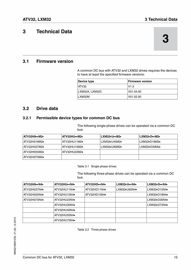
3.1 Firmware version
A common DC bus with ATV32 and LXM32 drives requires the devices to have at least the specified firmware versions:
3.2 Drive data
3.2.1 Permissible device types for common DC bus
The following single-phase drives can be operated via a common DC bus:
Table 3.1 Single-phase drives
The following three-phase drives can be operated via a common DC bus:
Table 3.2 Three-phase drives
Device type Firmware version
ATV32 V1.3
LXM32A, LXM32C V01.04.00
LXM32M V01.02.00
ATV32H0••M2• ATV32HU••M2• LXM32•U••M2• LXM32•D••M2•
ATV32H018M2• ATV32HU11M2• LXM32•U45M2• LXM32•D18M2•
ATV32H037M2• ATV32HU15M2• LXM32•U90M2• LXM32•D30M2•
ATV32H055M2• ATV32HU22M2•
ATV32H075M2•
ATV32H0••N4• ATV32HU••N4• ATV32HD••N4• LXM32•U••N4• LXM32•D••N4•
ATV32H037N4• ATV32HU11N4• ATV32HD11N4• LXM32•U60N4• LXM32•D12N4•
ATV32H055N4• ATV32HU15N4• ATV32HD15N4• LXM32•D18N4•
ATV32H075N4• ATV32HU22N4• LXM32•D30N4•
ATV32HU30N4• LXM32•D72N4•
ATV32HU40N4•
ATV32HU55N4•
ATV32HU75N4•
16 Common DC bus for ATV32, LXM32
3 Technical Data ATV32, LXM32
MN
A01
M00
1EN
, V1.
00, 1
2.20
10
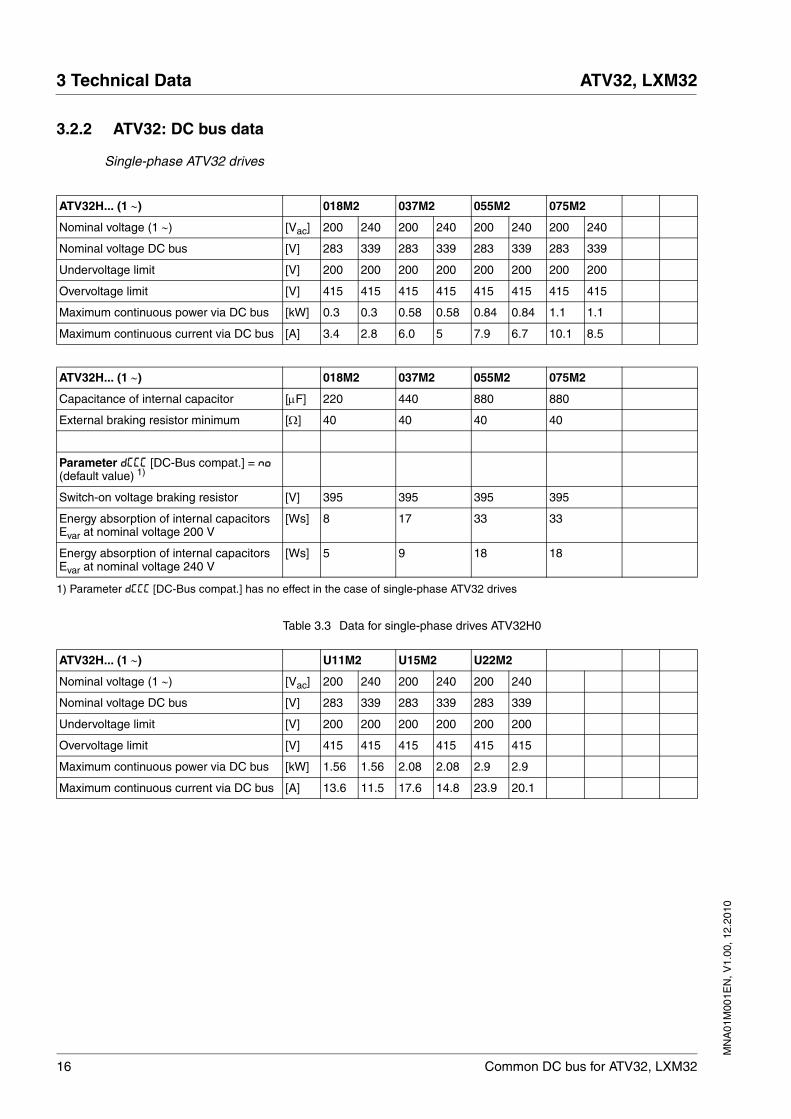
3.2.2 ATV32: DC bus data
Single-phase ATV32 drives
Table 3.3 Data for single-phase drives ATV32H0
ATV32H... (1 ∼) 018M2 037M2 055M2 075M2
Nominal voltage (1 ∼) [Vac] 200 240 200 240 200 240 200 240
Nominal voltage DC bus [V] 283 339 283 339 283 339 283 339
Undervoltage limit [V] 200 200 200 200 200 200 200 200
Overvoltage limit [V] 415 415 415 415 415 415 415 415
Maximum continuous power via DC bus [kW] 0.3 0.3 0.58 0.58 0.84 0.84 1.1 1.1
Maximum continuous current via DC bus [A] 3.4 2.8 6.0 5 7.9 6.7 10.1 8.5
ATV32H... (1 ∼) 018M2 037M2 055M2 075M2
Capacitance of internal capacitor [μF] 220 440 880 880
External braking resistor minimum [Ω] 40 40 40 40
Parameter dCCC [DC-Bus compat.] = NO (default value) 1)
Switch-on voltage braking resistor [V] 395 395 395 395
Energy absorption of internal capacitors Evar at nominal voltage 200 V
[Ws] 8 17 33 33
Energy absorption of internal capacitors Evar at nominal voltage 240 V
[Ws] 5 9 18 18
1) Parameter dCCC [DC-Bus compat.] has no effect in the case of single-phase ATV32 drives
ATV32H... (1 ∼) U11M2 U15M2 U22M2
Nominal voltage (1 ∼) [Vac] 200 240 200 240 200 240
Nominal voltage DC bus [V] 283 339 283 339 283 339
Undervoltage limit [V] 200 200 200 200 200 200
Overvoltage limit [V] 415 415 415 415 415 415
Maximum continuous power via DC bus [kW] 1.56 1.56 2.08 2.08 2.9 2.9
Maximum continuous current via DC bus [A] 13.6 11.5 17.6 14.8 23.9 20.1
MN
A01
M00
1EN
, V1.
00, 1
2.20
10
ATV32, LXM32 3 Technical Data
Common DC bus for ATV32, LXM32 17
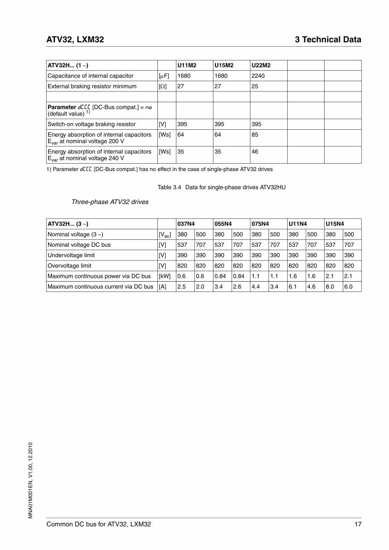
Table 3.4 Data for single-phase drives ATV32HU
Three-phase ATV32 drives
ATV32H... (1 ∼) U11M2 U15M2 U22M2
Capacitance of internal capacitor [μF] 1680 1680 2240
External braking resistor minimum [Ω] 27 27 25
Parameter dCCC [DC-Bus compat.] = NO (default value) 1)
Switch-on voltage braking resistor [V] 395 395 395
Energy absorption of internal capacitors Evar at nominal voltage 200 V
[Ws] 64 64 85
Energy absorption of internal capacitors Evar at nominal voltage 240 V
[Ws] 35 35 46
1) Parameter dCCC [DC-Bus compat.] has no effect in the case of single-phase ATV32 drives
ATV32H... (3 ∼) 037N4 055N4 075N4 U11N4 U15N4
Nominal voltage (3 ∼) [Vac] 380 500 380 500 380 500 380 500 380 500
Nominal voltage DC bus [V] 537 707 537 707 537 707 537 707 537 707
Undervoltage limit [V] 390 390 390 390 390 390 390 390 390 390
Overvoltage limit [V] 820 820 820 820 820 820 820 820 820 820
Maximum continuous power via DC bus [kW] 0.6 0.6 0.84 0.84 1.1 1.1 1.6 1.6 2.1 2.1
Maximum continuous current via DC bus [A] 2.5 2.0 3.4 2.6 4.4 3.4 6.1 4.6 8.0 6.0
18 Common DC bus for ATV32, LXM32
3 Technical Data ATV32, LXM32
MN
A01
M00
1EN
, V1.
00, 1
2.20
10
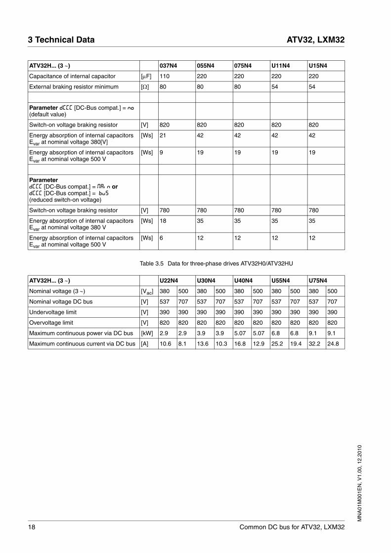
Table 3.5 Data for three-phase drives ATV32H0/ATV32HU
ATV32H... (3 ∼) 037N4 055N4 075N4 U11N4 U15N4
Capacitance of internal capacitor [μF] 110 220 220 220 220
External braking resistor minimum [Ω] 80 80 80 54 54
Parameter dCCC [DC-Bus compat.] = NO (default value)
Switch-on voltage braking resistor [V] 820 820 820 820 820
Energy absorption of internal capacitors Evar at nominal voltage 380[V]
[Ws] 21 42 42 42 42
Energy absorption of internal capacitors Evar at nominal voltage 500 V
[Ws] 9 19 19 19 19
ParameterdCCC [DC-Bus compat.] = Main ordCCC [DC-Bus compat.] = bus(reduced switch-on voltage)
Switch-on voltage braking resistor [V] 780 780 780 780 780
Energy absorption of internal capacitors Evar at nominal voltage 380 V
[Ws] 18 35 35 35 35
Energy absorption of internal capacitors Evar at nominal voltage 500 V
[Ws] 6 12 12 12 12
ATV32H... (3 ∼) U22N4 U30N4 U40N4 U55N4 U75N4
Nominal voltage (3 ∼) [Vac] 380 500 380 500 380 500 380 500 380 500
Nominal voltage DC bus [V] 537 707 537 707 537 707 537 707 537 707
Undervoltage limit [V] 390 390 390 390 390 390 390 390 390 390
Overvoltage limit [V] 820 820 820 820 820 820 820 820 820 820
Maximum continuous power via DC bus [kW] 2.9 2.9 3.9 3.9 5.07 5.07 6.8 6.8 9.1 9.1
Maximum continuous current via DC bus [A] 10.6 8.1 13.6 10.3 16.8 12.9 25.2 19.4 32.2 24.8
MN
A01
M00
1EN
, V1.
00, 1
2.20
10
ATV32, LXM32 3 Technical Data
Common DC bus for ATV32, LXM32 19
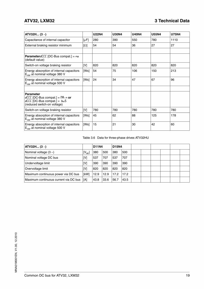
Table 3.6 Data for three-phase drives ATV32HU
ATV32H... (3 ∼) U22N4 U30N4 U40N4 U55N4 U75N4
Capacitance of internal capacitor [μF] 280 390 550 780 1110
External braking resistor minimum [Ω] 54 54 36 27 27
ParameterdCCC [DC-Bus compat.] = NO (default value)
Switch-on voltage braking resistor [V] 820 820 820 820 820
Energy absorption of internal capacitors Evar at nominal voltage 380 V
[Ws] 54 75 106 150 213
Energy absorption of internal capacitors Evar at nominal voltage 500 V
[Ws] 24 34 47 67 96
ParameterdCCC [DC-Bus compat.] = Main ordCCC [DC-Bus compat.] = bus(reduced switch-on voltage)
Switch-on voltage braking resistor [V] 780 780 780 780 780
Energy absorption of internal capacitors Evar at nominal voltage 380 V
[Ws] 45 62 88 125 178
Energy absorption of internal capacitors Evar at nominal voltage 500 V
[Ws] 15 21 30 42 60
ATV32H... (3 ∼) D11N4 D15N4
Nominal voltage (3 ∼) [Vac] 380 500 380 500
Nominal voltage DC bus [V] 537 707 537 707
Undervoltage limit [V] 390 390 390 390
Overvoltage limit [V] 820 820 820 820
Maximum continuous power via DC bus [kW] 12.9 12.9 17.2 17.2
Maximum continuous current via DC bus [A] 43.8 33.6 56.7 43.5
20 Common DC bus for ATV32, LXM32
3 Technical Data ATV32, LXM32
MN
A01
M00
1EN
, V1.
00, 1
2.20
10
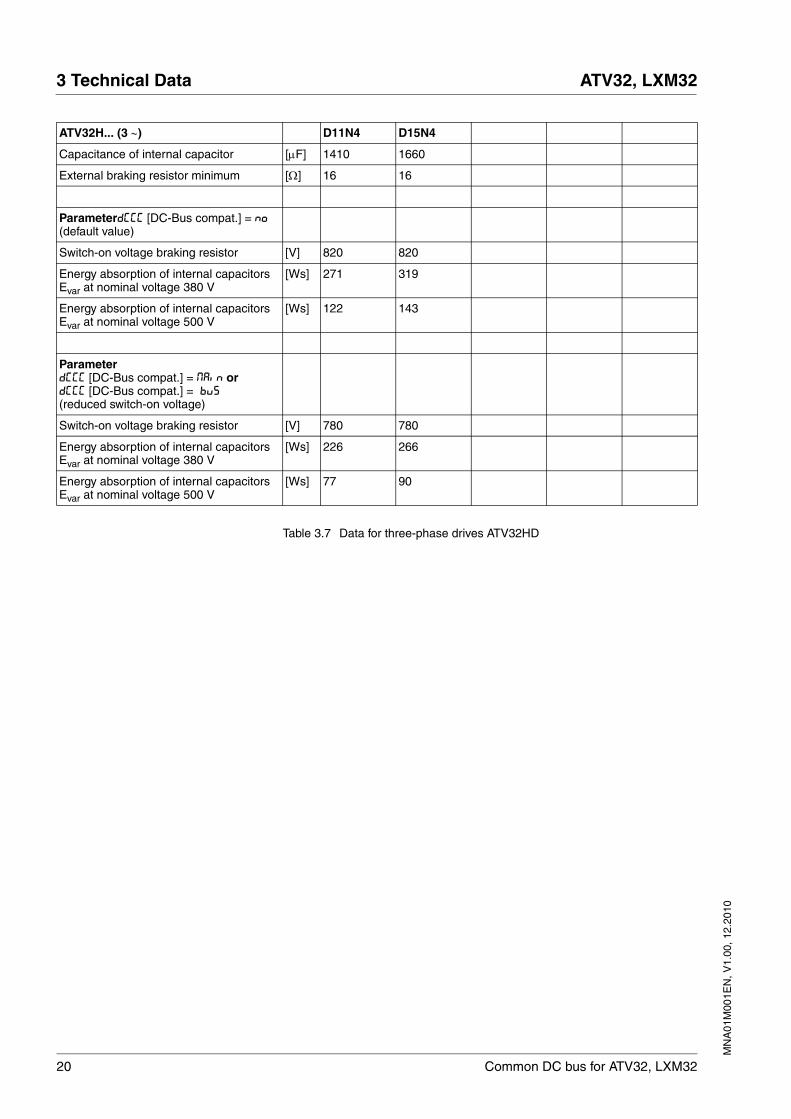
Table 3.7 Data for three-phase drives ATV32HD
ATV32H... (3 ∼) D11N4 D15N4
Capacitance of internal capacitor [μF] 1410 1660
External braking resistor minimum [Ω] 16 16
ParameterdCCC [DC-Bus compat.] = NO (default value)
Switch-on voltage braking resistor [V] 820 820
Energy absorption of internal capacitors Evar at nominal voltage 380 V
[Ws] 271 319
Energy absorption of internal capacitors Evar at nominal voltage 500 V
[Ws] 122 143
ParameterdCCC [DC-Bus compat.] = Main ordCCC [DC-Bus compat.] = bus(reduced switch-on voltage)
Switch-on voltage braking resistor [V] 780 780
Energy absorption of internal capacitors Evar at nominal voltage 380 V
[Ws] 226 266
Energy absorption of internal capacitors Evar at nominal voltage 500 V
[Ws] 77 90
MN
A01
M00
1EN
, V1.
00, 1
2.20
10
ATV32, LXM32 3 Technical Data
Common DC bus for ATV32, LXM32 21
3.2.3 LXM32: DC bus data
Single-phase LXM32 drives
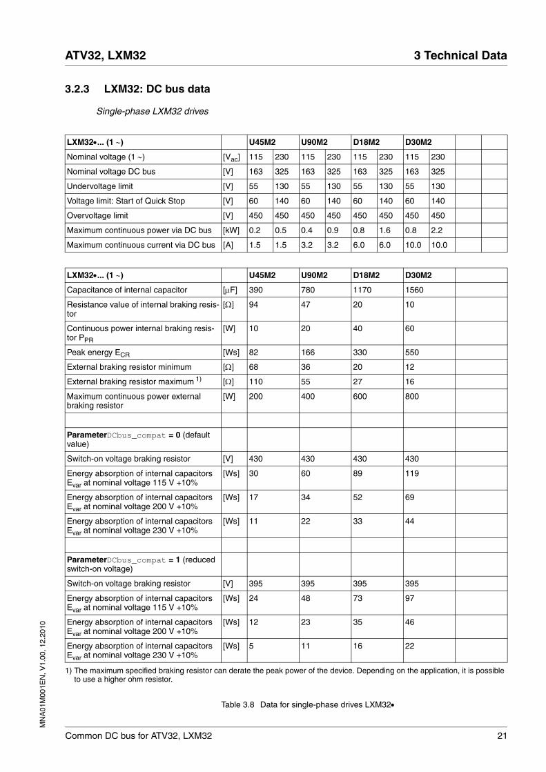
Table 3.8 Data for single-phase drives LXM32•
LXM32•... (1 ∼) U45M2 U90M2 D18M2 D30M2
Nominal voltage (1 ∼) [Vac] 115 230 115 230 115 230 115 230
Nominal voltage DC bus [V] 163 325 163 325 163 325 163 325
Undervoltage limit [V] 55 130 55 130 55 130 55 130
Voltage limit: Start of Quick Stop [V] 60 140 60 140 60 140 60 140
Overvoltage limit [V] 450 450 450 450 450 450 450 450
Maximum continuous power via DC bus [kW] 0.2 0.5 0.4 0.9 0.8 1.6 0.8 2.2
Maximum continuous current via DC bus [A] 1.5 1.5 3.2 3.2 6.0 6.0 10.0 10.0
LXM32•... (1 ∼) U45M2 U90M2 D18M2 D30M2
Capacitance of internal capacitor [μF] 390 780 1170 1560
Resistance value of internal braking resis-tor
[Ω] 94 47 20 10
Continuous power internal braking resis-tor PPR
[W] 10 20 40 60
Peak energy ECR [Ws] 82 166 330 550
External braking resistor minimum [Ω] 68 36 20 12
External braking resistor maximum 1) [Ω] 110 55 27 16
Maximum continuous power external braking resistor
[W] 200 400 600 800
ParameterDCbus_compat = 0 (default value)
Switch-on voltage braking resistor [V] 430 430 430 430
Energy absorption of internal capacitors Evar at nominal voltage 115 V +10%
[Ws] 30 60 89 119
Energy absorption of internal capacitors Evar at nominal voltage 200 V +10%
[Ws] 17 34 52 69
Energy absorption of internal capacitors Evar at nominal voltage 230 V +10%
[Ws] 11 22 33 44
ParameterDCbus_compat = 1 (reduced switch-on voltage)
Switch-on voltage braking resistor [V] 395 395 395 395
Energy absorption of internal capacitors Evar at nominal voltage 115 V +10%
[Ws] 24 48 73 97
Energy absorption of internal capacitors Evar at nominal voltage 200 V +10%
[Ws] 12 23 35 46
Energy absorption of internal capacitors Evar at nominal voltage 230 V +10%
[Ws] 5 11 16 22
1) The maximum specified braking resistor can derate the peak power of the device. Depending on the application, it is possible to use a higher ohm resistor.
22 Common DC bus for ATV32, LXM32
3 Technical Data ATV32, LXM32
MN
A01
M00
1EN
, V1.
00, 1
2.20
10
Three-phase LXM32 drives
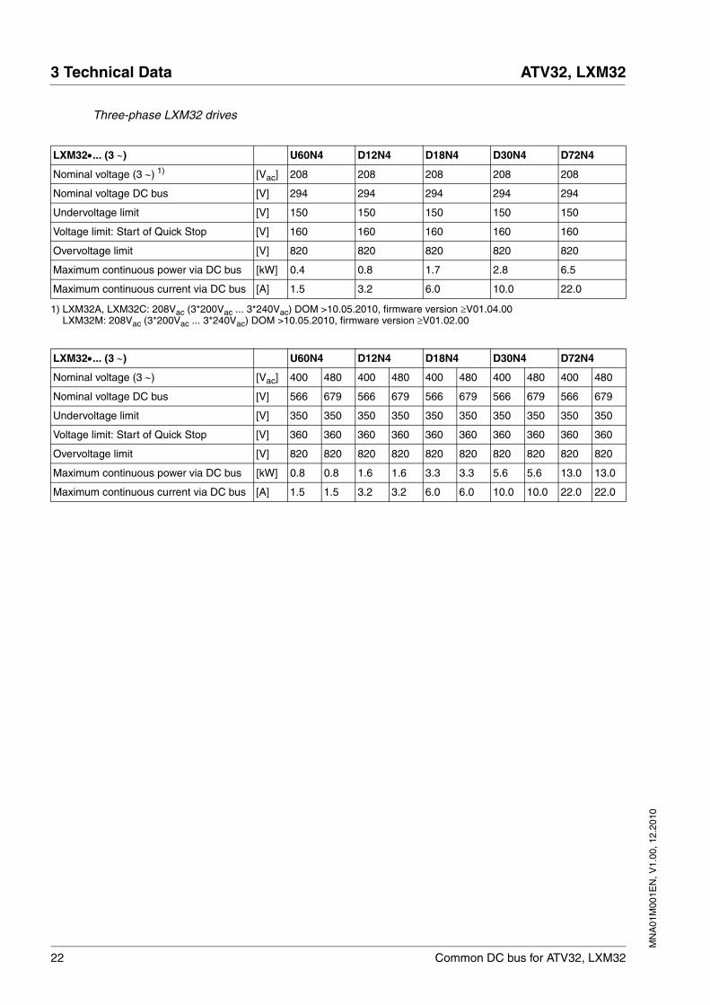
LXM32•... (3 ∼) U60N4 D12N4 D18N4 D30N4 D72N4
Nominal voltage (3 ∼) 1) [Vac] 208 208 208 208 208
Nominal voltage DC bus [V] 294 294 294 294 294
Undervoltage limit [V] 150 150 150 150 150
Voltage limit: Start of Quick Stop [V] 160 160 160 160 160
Overvoltage limit [V] 820 820 820 820 820
Maximum continuous power via DC bus [kW] 0.4 0.8 1.7 2.8 6.5
Maximum continuous current via DC bus [A] 1.5 3.2 6.0 10.0 22.0
1) LXM32A, LXM32C: 208Vac (3*200Vac ... 3*240Vac) DOM >10.05.2010, firmware version ≥V01.04.00LXM32M: 208Vac (3*200Vac ... 3*240Vac) DOM >10.05.2010, firmware version ≥V01.02.00
LXM32•... (3 ∼) U60N4 D12N4 D18N4 D30N4 D72N4
Nominal voltage (3 ∼) [Vac] 400 480 400 480 400 480 400 480 400 480
Nominal voltage DC bus [V] 566 679 566 679 566 679 566 679 566 679
Undervoltage limit [V] 350 350 350 350 350 350 350 350 350 350
Voltage limit: Start of Quick Stop [V] 360 360 360 360 360 360 360 360 360 360
Overvoltage limit [V] 820 820 820 820 820 820 820 820 820 820
Maximum continuous power via DC bus [kW] 0.8 0.8 1.6 1.6 3.3 3.3 5.6 5.6 13.0 13.0
Maximum continuous current via DC bus [A] 1.5 1.5 3.2 3.2 6.0 6.0 10.0 10.0 22.0 22.0
MN
A01
M00
1EN
, V1.
00, 1
2.20
10
ATV32, LXM32 3 Technical Data
Common DC bus for ATV32, LXM32 23
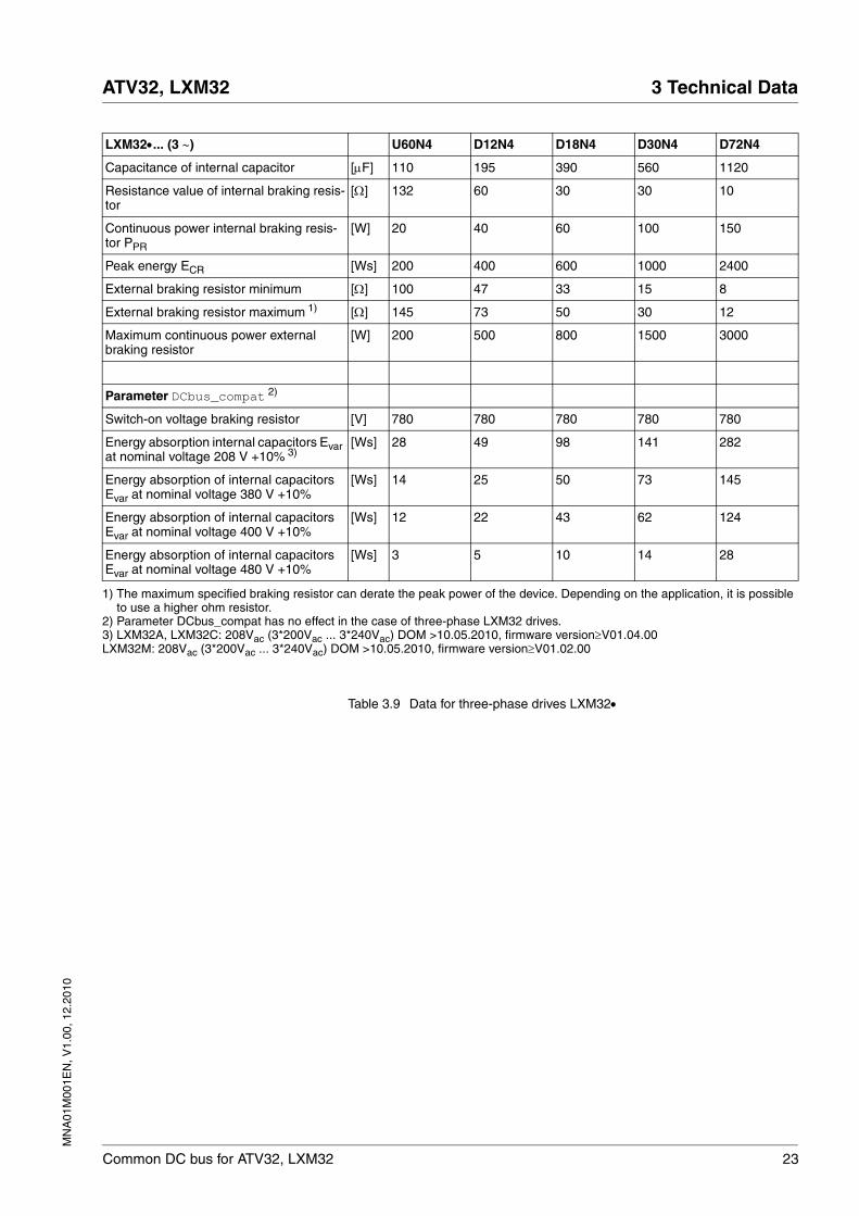
Table 3.9 Data for three-phase drives LXM32•
LXM32•... (3 ∼) U60N4 D12N4 D18N4 D30N4 D72N4
Capacitance of internal capacitor [μF] 110 195 390 560 1120
Resistance value of internal braking resis-tor
[Ω] 132 60 30 30 10
Continuous power internal braking resis-tor PPR
[W] 20 40 60 100 150
Peak energy ECR [Ws] 200 400 600 1000 2400
External braking resistor minimum [Ω] 100 47 33 15 8
External braking resistor maximum 1) [Ω] 145 73 50 30 12
Maximum continuous power external braking resistor
[W] 200 500 800 1500 3000
Parameter DCbus_compat 2)
Switch-on voltage braking resistor [V] 780 780 780 780 780
Energy absorption internal capacitors Evar at nominal voltage 208 V +10% 3)
[Ws] 28 49 98 141 282
Energy absorption of internal capacitors Evar at nominal voltage 380 V +10%
[Ws] 14 25 50 73 145
Energy absorption of internal capacitors Evar at nominal voltage 400 V +10%
[Ws] 12 22 43 62 124
Energy absorption of internal capacitors Evar at nominal voltage 480 V +10%
[Ws] 3 5 10 14 28
1) The maximum specified braking resistor can derate the peak power of the device. Depending on the application, it is possible to use a higher ohm resistor.
2) Parameter DCbus_compat has no effect in the case of three-phase LXM32 drives.3) LXM32A, LXM32C: 208Vac (3*200Vac ... 3*240Vac) DOM >10.05.2010, firmware version≥V01.04.00LXM32M: 208Vac (3*200Vac ... 3*240Vac) DOM >10.05.2010, firmware version≥V01.02.00
24 Common DC bus for ATV32, LXM32
3 Technical Data ATV32, LXM32
MN
A01
M00
1EN
, V1.
00, 1
2.20
10
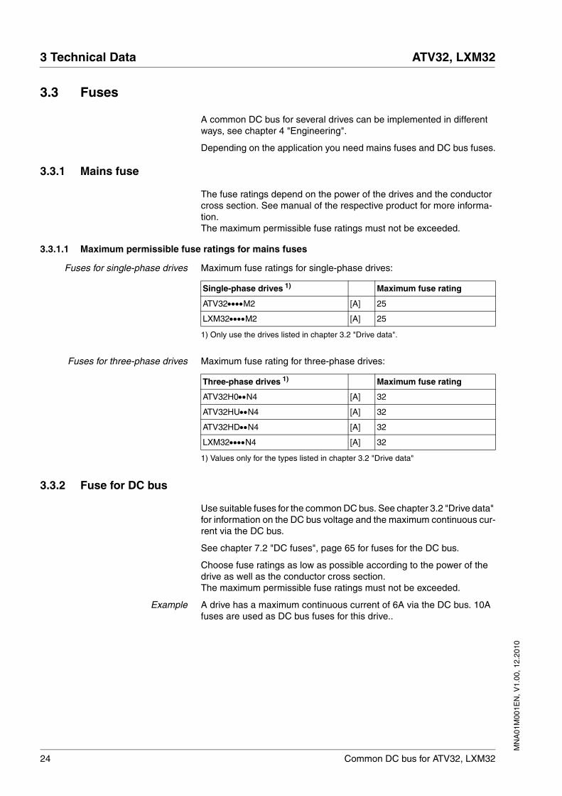
3.3 Fuses
A common DC bus for several drives can be implemented in different ways, see chapter 4 "Engineering".
Depending on the application you need mains fuses and DC bus fuses.
3.3.1 Mains fuse
The fuse ratings depend on the power of the drives and the conductor cross section. See manual of the respective product for more informa-tion.The maximum permissible fuse ratings must not be exceeded.
3.3.1.1 Maximum permissible fuse ratings for mains fuses
Fuses for single-phase drives Maximum fuse ratings for single-phase drives:
Fuses for three-phase drives Maximum fuse rating for three-phase drives:
3.3.2 Fuse for DC bus
Use suitable fuses for the common DC bus. See chapter 3.2 "Drive data" for information on the DC bus voltage and the maximum continuous cur-rent via the DC bus.
See chapter 7.2 "DC fuses", page 65 for fuses for the DC bus.
Choose fuse ratings as low as possible according to the power of the drive as well as the conductor cross section.The maximum permissible fuse ratings must not be exceeded.
Example A drive has a maximum continuous current of 6A via the DC bus. 10A fuses are used as DC bus fuses for this drive..
Single-phase drives 1)
1) Only use the drives listed in chapter 3.2 "Drive data".
Maximum fuse rating
ATV32••••M2 [A] 25
LXM32••••M2 [A] 25
Three-phase drives 1)
1) Values only for the types listed in chapter 3.2 "Drive data"
Maximum fuse rating
ATV32H0••N4 [A] 32
ATV32HU••N4 [A] 32
ATV32HD••N4 [A] 32
LXM32••••N4 [A] 32
MN
A01
M00
1EN
, V1.
00, 1
2.20
10
ATV32, LXM32 3 Technical Data
Common DC bus for ATV32, LXM32 25
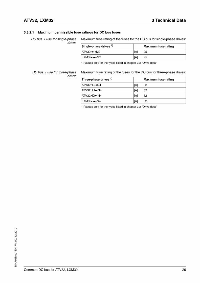
3.3.2.1 Maximum permissible fuse ratings for DC bus fuses
DC bus: Fuse for single-phasedrives
Maximum fuse rating of the fuses for the DC bus for single-phase drives:
DC bus: Fuse for three-phasedrives
Maximum fuse rating of the fuses for the DC bus for three-phase drives:
Single-phase drives 1)
1) Values only for the types listed in chapter 3.2 "Drive data"
Maximum fuse rating
ATV32••••M2 [A] 25
LXM32••••M2 [A] 25
Three-phase drives 1)
1) Values only for the types listed in chapter 3.2 "Drive data"
Maximum fuse rating
ATV32H0••N4 [A] 32
ATV32HU••N4 [A] 32
ATV32HD••N4 [A] 32
LXM32••••N4 [A] 32
26 Common DC bus for ATV32, LXM32
3 Technical Data ATV32, LXM32
MN
A01
M00
1EN
, V1.
00, 1
2.20
10
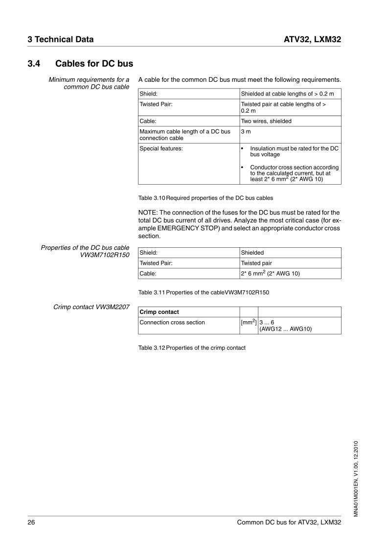
3.4 Cables for DC bus
Minimum requirements for acommon DC bus cable
A cable for the common DC bus must meet the following requirements.
Table 3.10Required properties of the DC bus cables
NOTE: The connection of the fuses for the DC bus must be rated for the total DC bus current of all drives. Analyze the most critical case (for ex-ample EMERGENCY STOP) and select an appropriate conductor cross section.
Properties of the DC bus cableVW3M7102R150
Table 3.11Properties of the cableVW3M7102R150
Crimp contact VW3M2207
Table 3.12Properties of the crimp contact
Shield: Shielded at cable lengths of > 0.2 m
Twisted Pair: Twisted pair at cable lengths of > 0.2 m
Cable: Two wires, shielded
Maximum cable length of a DC bus connection cable
3 m
Special features: • Insulation must be rated for the DC bus voltage
• Conductor cross section according to the calculated current, but at least 2* 6 mm2 (2* AWG 10)
Shield: Shielded
Twisted Pair: Twisted pair
Cable: 2* 6 mm2 (2* AWG 10)
Crimp contact
Connection cross section [mm2] 3 ... 6(AWG12 ... AWG10)
MN
A01
M00
1EN
, V1.
00, 1
2.20
10
ATV32, LXM32 3 Technical Data
Common DC bus for ATV32, LXM32 27
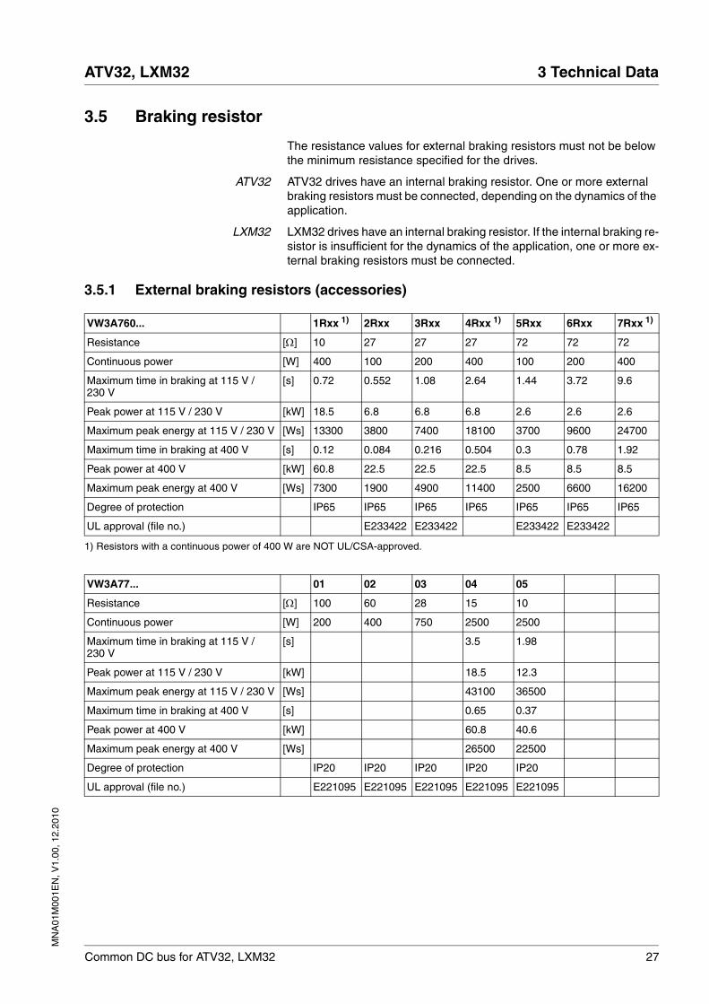
3.5 Braking resistor
The resistance values for external braking resistors must not be below the minimum resistance specified for the drives.
ATV32 ATV32 drives have an internal braking resistor. One or more external braking resistors must be connected, depending on the dynamics of the application.
LXM32 LXM32 drives have an internal braking resistor. If the internal braking re-sistor is insufficient for the dynamics of the application, one or more ex-ternal braking resistors must be connected.
3.5.1 External braking resistors (accessories)
VW3A760... 1Rxx 1) 2Rxx 3Rxx 4Rxx 1) 5Rxx 6Rxx 7Rxx 1)
Resistance [Ω] 10 27 27 27 72 72 72
Continuous power [W] 400 100 200 400 100 200 400
Maximum time in braking at 115 V / 230 V
[s] 0.72 0.552 1.08 2.64 1.44 3.72 9.6
Peak power at 115 V / 230 V [kW] 18.5 6.8 6.8 6.8 2.6 2.6 2.6
Maximum peak energy at 115 V / 230 V [Ws] 13300 3800 7400 18100 3700 9600 24700
Maximum time in braking at 400 V [s] 0.12 0.084 0.216 0.504 0.3 0.78 1.92
Peak power at 400 V [kW] 60.8 22.5 22.5 22.5 8.5 8.5 8.5
Maximum peak energy at 400 V [Ws] 7300 1900 4900 11400 2500 6600 16200
Degree of protection IP65 IP65 IP65 IP65 IP65 IP65 IP65
UL approval (file no.) E233422 E233422 E233422 E233422
1) Resistors with a continuous power of 400 W are NOT UL/CSA-approved.
VW3A77... 01 02 03 04 05
Resistance [Ω] 100 60 28 15 10
Continuous power [W] 200 400 750 2500 2500
Maximum time in braking at 115 V / 230 V
[s] 3.5 1.98
Peak power at 115 V / 230 V [kW] 18.5 12.3
Maximum peak energy at 115 V / 230 V [Ws] 43100 36500
Maximum time in braking at 400 V [s] 0.65 0.37
Peak power at 400 V [kW] 60.8 40.6
Maximum peak energy at 400 V [Ws] 26500 22500
Degree of protection IP20 IP20 IP20 IP20 IP20
UL approval (file no.) E221095 E221095 E221095 E221095 E221095
28 Common DC bus for ATV32, LXM32
3 Technical Data ATV32, LXM32
MN
A01
M00
1EN
, V1.
00, 1
2.20
10
3.6 Mains filter
The fuse rating upstream of the common external mains filter must not be greater than the nominal current of the external mains filter.
NOTE: Three-phase mains filters do not have a neutral conductor con-nection; they are only approved for three-phase devices.
See the manual of the respective product for information on external mains filters.
3.7 Mains reactors
If one drive requires a mains reactor, then all drives connected via the DC bus must be equipped with mains reactors.
The fuse rating upstream of the common mains reactor must not be greater than the nominal current of the mains reactor.
See the manual of the respective product for information on mains reac-tors.
MN
A01
M00
1EN
, V1.
00, 1
2.20
10
ATV32, LXM32 4 Engineering
Common DC bus for ATV32, LXM32 29
44 Engineering
This chapter provides engineering information for a common DC bus for several drives.
ATV32: See the "Altivar 32 - Installation manual" for vital engineering in-formation concerning the ATV32 drive.
LXM32: See the Engineering chapter in the LXM32 product manual for vital engineering information concerning the LXM32 drive.
4.1 EMC specifics
If drives are to be operated via a common DC bus, the following aspects must be considered in terms of EMC:
• Keep DC bus cables as short as possible.
• Shielded DC bus cables must be used at a cable length of > 0.2 m. In the case of shielded DC bus cables, connect the cable shield to the shield connection (large surface area contact).
@ WARNINGDESTRUCTION OF SYSTEM COMPONENTS AND LOSS OF CONTROL
Incorrect use of a parallel connection of the DC bus may destroy the drives immediately or after a delay.
• Note the requirements concerning the use of a parallel DC bus connection.
Failure to follow these instructions can result in death, serious injury or equipment damage.
Page
4.1 "EMC specifics" 29
4.2 "Mounting distances" 30
4.3 "Energy balance" 30
4.4 "Prerequisites for a common DC bus" 33
4.5 "Structure of a common DC bus"
• 4.5.1 "Common mains fuses"
• 4.5.2 "Separate mains fuses"
• 4.5.3 "DC supply via a drive"
• 4.5.4 "DC supply via DC power supply unit"
34
4.6 "Accessories for the common DC bus" 43
30 Common DC bus for ATV32, LXM32
4 Engineering ATV32, LXM32
MN
A01
M00
1EN
, V1.
00, 1
2.20
10
4.2 Mounting distances
When planning mounting distances, consider the space required for the DC bus cables.
4.3 Energy balance
To be able to estimate the effect of a planned interconnection of drives, you should create an energy balance of the individual drives over a movement cycle.A movement cycle consists of the following phases: acceleration, con-tinuous movement and deceleration.
The energy generated during deceleration can be used by other drives connected via a common DC bus. Excess energy must be absorbed by the braking resistors.
MN
A01
M00
1EN
, V1.
00, 1
2.20
10
ATV32, LXM32 4 Engineering
Common DC bus for ATV32, LXM32 31
4.3.1 Energy absorption
Energy absorption is influenced by the following factors:
• DC bus capacitors Evar in the drive
• Electrical losses of the drive system Eel
• Mechanical losses of the facility and the drive system Emech
• Braking resistor EB
The energy Evar is the square difference between the voltage prior to de-celeration and the response threshold.
The energy absorption through the DC bus capacitors is lowest when the voltage is highest. In the calculation, use the values of the highest mains voltage.
Electrical losses Eel The electrical losses Eel of the drive system can be estimated on the ba-sis of the peak power of the drive. The maximum power dissipation is ap-proximately 10% of the peak power at a typical efficiency of 90%. If the current during deceleration is lower, the power dissipation is reduced ac-cordingly.
Mechanical losses Emech The mechanical losses result from friction during operation of the sys-tem. Mechanical losses are negligible if the time required by the system to coast to a stop without a driving force is considerably longer than the time required to decelerate the system. The mechanical losses can be calculated from the load torque and the velocity from which the motor is to stop.
Braking resistor Two characteristic values determine the energy absorption of a braking resistor.
• The continuous power PPR is the amount of energy that can be con-tinuously absorbed without overloading the braking resistor.
• The maximum energy ECR limits the maximum short-term power that can be absorbed.
32 Common DC bus for ATV32, LXM32
4 Engineering ATV32, LXM32
MN
A01
M00
1EN
, V1.
00, 1
2.20
10
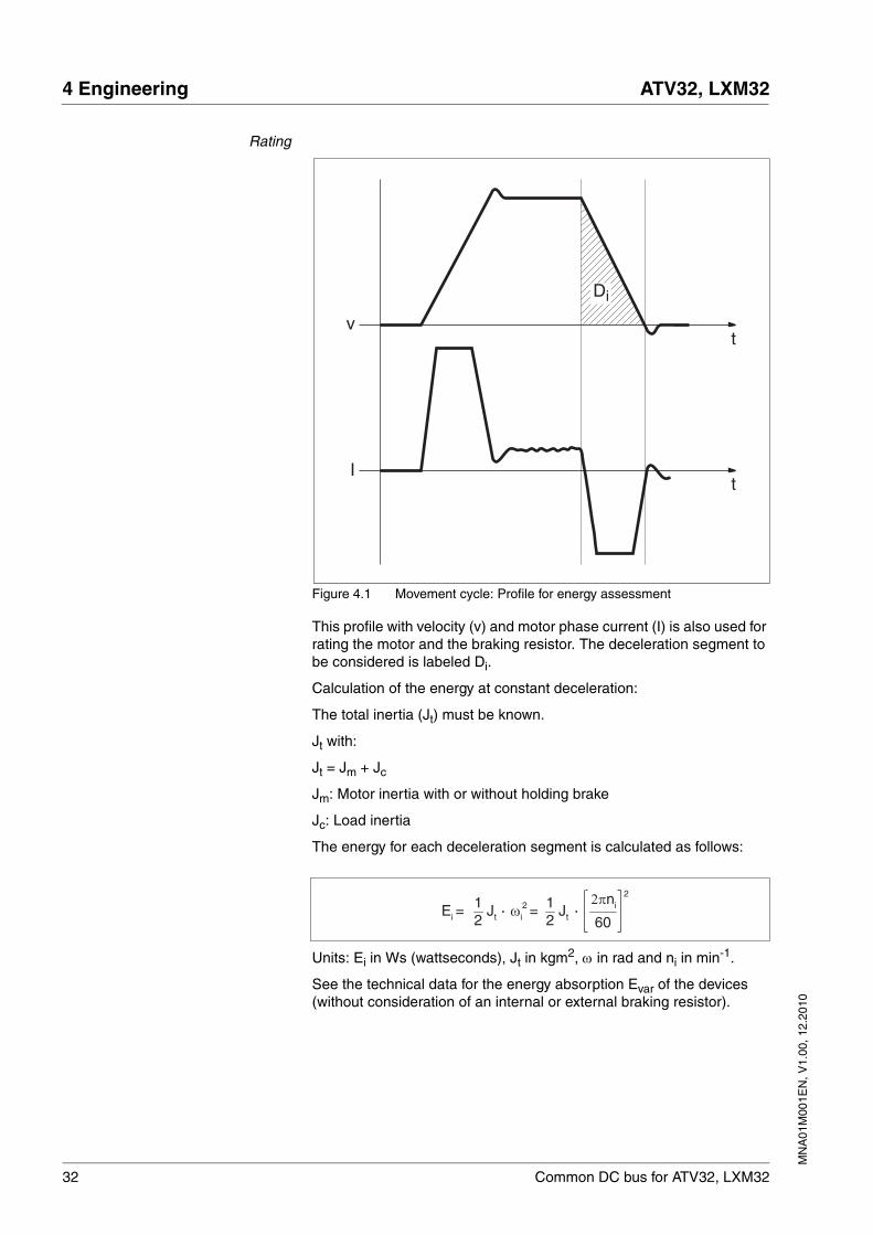
Rating
Figure 4.1 Movement cycle: Profile for energy assessment
This profile with velocity (v) and motor phase current (I) is also used for rating the motor and the braking resistor. The deceleration segment to be considered is labeled Di.
Calculation of the energy at constant deceleration:
The total inertia (Jt) must be known.
Jt with:
Jt = Jm + Jc
Jm: Motor inertia with or without holding brake
Jc: Load inertia
The energy for each deceleration segment is calculated as follows:
Units: Ei in Ws (wattseconds), Jt in kgm2, ω in rad and ni in min-1.
See the technical data for the energy absorption Evar of the devices (without consideration of an internal or external braking resistor).
v
I
t
t
Di
2πni 2
60ωi
2 = Ei = Jt12
Jt12
MN
A01
M00
1EN
, V1.
00, 1
2.20
10
ATV32, LXM32 4 Engineering
Common DC bus for ATV32, LXM32 33
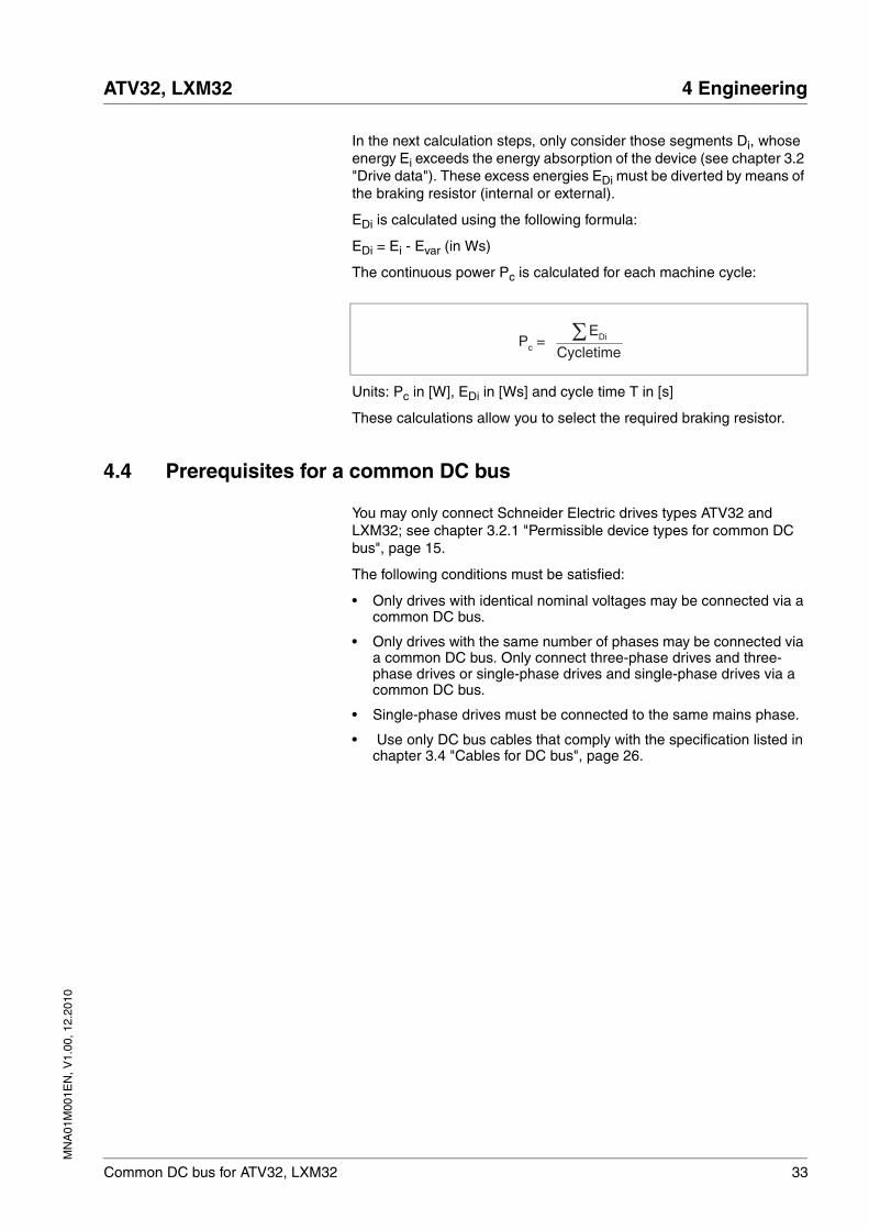
In the next calculation steps, only consider those segments Di, whose energy Ei exceeds the energy absorption of the device (see chapter 3.2 "Drive data"). These excess energies EDi must be diverted by means of the braking resistor (internal or external).
EDi is calculated using the following formula:
EDi = Ei - Evar (in Ws)
The continuous power Pc is calculated for each machine cycle:
Units: Pc in [W], EDi in [Ws] and cycle time T in [s]
These calculations allow you to select the required braking resistor.
4.4 Prerequisites for a common DC bus
You may only connect Schneider Electric drives types ATV32 and LXM32; see chapter 3.2.1 "Permissible device types for common DC bus", page 15.
The following conditions must be satisfied:
• Only drives with identical nominal voltages may be connected via a common DC bus.
• Only drives with the same number of phases may be connected via a common DC bus. Only connect three-phase drives and three-phase drives or single-phase drives and single-phase drives via a common DC bus.
• Single-phase drives must be connected to the same mains phase.
• Use only DC bus cables that comply with the specification listed in chapter 3.4 "Cables for DC bus", page 26.
Pc = CycletimeΣEDi
34 Common DC bus for ATV32, LXM32
4 Engineering ATV32, LXM32
MN
A01
M00
1EN
, V1.
00, 1
2.20
10
4.5 Structure of a common DC bus
The structure of a common DC bus can differ according the require-ments. See the concepts below:
• Common mains fuse
• Separate mains fuses
• DC supply via a drive
• DC supply via DC power supply unit
4.5.1 Common mains fuses
All drives are connected to the mains supply via common mains fuses.
Conditions For DC bus connections for drives with common mains fuses the follow-ing conditions must be met:
• All drives have common mains fuses.
• The current of all drives supplied via the DC bus must not exceed the maximum values listed in the following table, even when regen-eration conditions are present. If the following maximum values are exceeded DC fuses must be used.
• Only drives with an identical number of phases may be connected via a common DC bus. Only connect three-phase drives and three-phase drives or single-phase drives and single-phase drives via a common DC bus.
• Only drives with identical nominal voltages may be connected via a common DC bus.
• ••M2 drives: Connect single-phase drives only to the same phase.
• Activate mains phase monitoring for all drives.
• If you want to operate ATV32•••• and LXM32•••• drives via a com-mon DC bus, you must activate the following parameters for each device:
• ATV32••••: The power of the ATV32•••• drives sharing a common DC bus may differ by a maximum of one level in continuous power. See chapter 3.2 "Drive data" for the maximum power of the drives.
• ATV32••••: Set the type of DC bus connection via parameter dCCM [DC-Bus chaining]. Additional conditions may apply for setting this parameter, see Altivar 32 Programming manual.
Single-phase drives ••M2 Three-phase drives ••N4
Maximum input current of all con-nected drives: 25 A.
Maximum input current of all con-nected drives: 32 A.
Single-phase drives ••M2 Three-phase drives ••N4
Maximum DC bus current: 25 A. Maximum DC bus current: 32 A.
Drive Parameter
ATV32•••• dCCC [DC-Bus compat.]
LXM32•••• DCbus_compat
MN
A01
M00
1EN
, V1.
00, 1
2.20
10
ATV32, LXM32 4 Engineering
Common DC bus for ATV32, LXM32 35
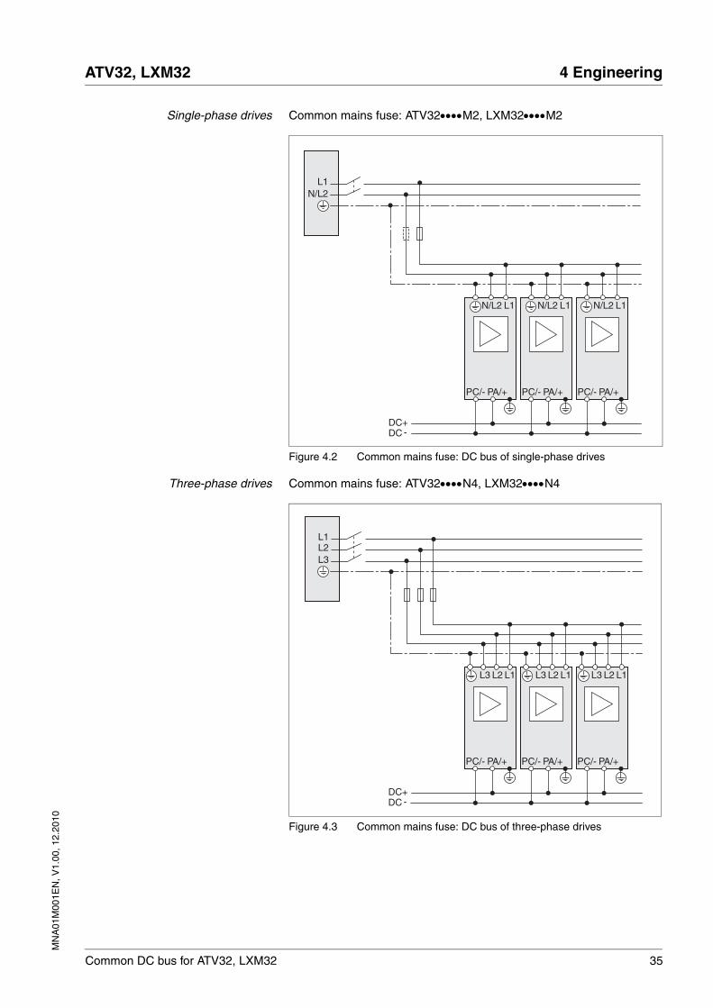
Single-phase drives Common mains fuse: ATV32••••M2, LXM32••••M2
Figure 4.2 Common mains fuse: DC bus of single-phase drives
Three-phase drives Common mains fuse: ATV32••••N4, LXM32••••N4
Figure 4.3 Common mains fuse: DC bus of three-phase drives
PC/- PA/+ PC/- PA/+ PC/- PA/+
DC+DC -
N/L2L1
N/L2 L1 N/L2 L1 N/L2 L1
PC/- PA/+ PC/- PA/+ PC/- PA/+
DC+DC -
L3L2L1
L2 L1L3 L2 L1L3L2 L1L3
36 Common DC bus for ATV32, LXM32
4 Engineering ATV32, LXM32
MN
A01
M00
1EN
, V1.
00, 1
2.20
10
4.5.2 Separate mains fuses
Each drive is connected to the mains supply via its own mains fuses.
Conditions The following conditions must be met for the DC bus connection of drives with separate mains fuses:
• Each individual drive requires its own mains fuses; see chapter 3.3.1 "Mains fuse", page 24.
• Separate fuses for the DC bus must be used for each individual drive. See chapter 3.3.2 "Fuse for DC bus", page 24 for permissible fuse ratings.
• Only drives with an identical number of phases may be connected via a common DC bus. Only connect three-phase drives and three-phase drives or single-phase drives and single-phase drives via a common DC bus.
• Only drives with identical nominal voltages may be connected via a common DC bus.
• ••M2 drives: Connect single-phase drives only to the same phase.
• Activate mains phase monitoring for all drives.
• If you want to operate ATV32•••• and LXM32•••• drives via a com-mon DC bus, you must activate the following parameters for each device:
• ATV32••••: The power of the ATV32•••• drives sharing a common DC bus may differ by a maximum of one level in continuous power. See chapter 3.2 "Drive data" for the maximum power of the drives.
• ATV32••••: Set the type of DC bus connection via parameter dCCM [DC-Bus chaining]. Additional conditions may apply for setting this parameter, see Altivar 32 Programming manual.
NOTE: The connection of the fuses for the DC bus must be rated for the total DC bus current of all drives. Analyze the most critical case in your application (for example EMERGENCY STOP) and select an appropri-ate conductor cross section.
Drive Parameter
ATV32•••• dCCC [DC-Bus compat.]
LXM32•••• DCbus_compat
MN
A01
M00
1EN
, V1.
00, 1
2.20
10
ATV32, LXM32 4 Engineering
Common DC bus for ATV32, LXM32 37
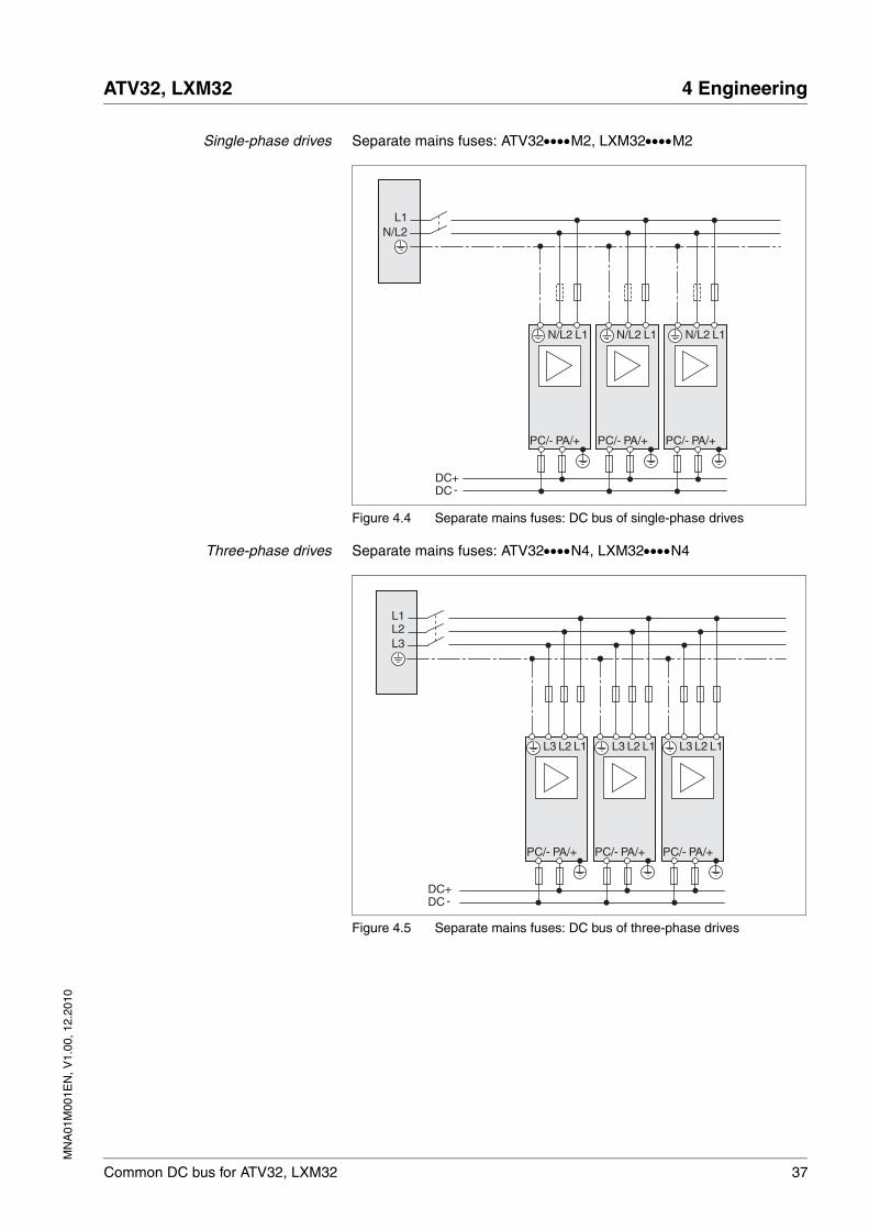
Single-phase drives Separate mains fuses: ATV32••••M2, LXM32••••M2
Figure 4.4 Separate mains fuses: DC bus of single-phase drives
Three-phase drives Separate mains fuses: ATV32••••N4, LXM32••••N4
Figure 4.5 Separate mains fuses: DC bus of three-phase drives
N/L2 L1
N/L2L1
N/L2 L1N/L2 L1
PC/- PA/+ PC/- PA/+ PC/- PA/+
DC+DC -
PC/- PA/+ PC/- PA/+ PC/- PA/+
L3L2L1
L2 L1L3 L2 L1L3L2 L1L3
DC+DC -
38 Common DC bus for ATV32, LXM32
4 Engineering ATV32, LXM32
MN
A01
M00
1EN
, V1.
00, 1
2.20
10
4.5.3 DC supply via a drive
The drives are supplied via an appropriately rated drive via the DC bus.
Conditions The following conditions must be met for the DC bus connection of drives with one supplying drive:
• Fuses must be used for the DC bus. See chapter 3.3.2 "Fuse for DC bus", page 24 for permissible fuse ratings.
• Only drives with an identical number of phases may be connected via a common DC bus. Only connect three-phase drives and three-phase drives or single-phase drives and single-phase drives via a common DC bus.
• Only drives with identical nominal voltages may be connected via a common DC bus.In the case of LXM32•••• drives, set the same voltage for all drives with the parameter MON_MainsVolt.
• If you want to operate ATV32•••• and LXM32•••• drives via a com-mon DC bus, you must activate the following parameters for each device:
• ATV32••••: Set the type of DC bus connection via parameter dCCM [DC-Bus chaining]. Additional conditions may apply for setting this parameter, see Altivar 32 Programming manual.
NOTE: The connection of the fuses for the DC bus must be rated for the total DC bus current of all drives. Analyze the most critical case in your application (for example EMERGENCY STOP) and select an appropri-ate conductor cross section.
Drive Parameter
ATV32•••• dCCC [DC-Bus compat.]
LXM32•••• DCbus_compat
MN
A01
M00
1EN
, V1.
00, 1
2.20
10
ATV32, LXM32 4 Engineering
Common DC bus for ATV32, LXM32 39
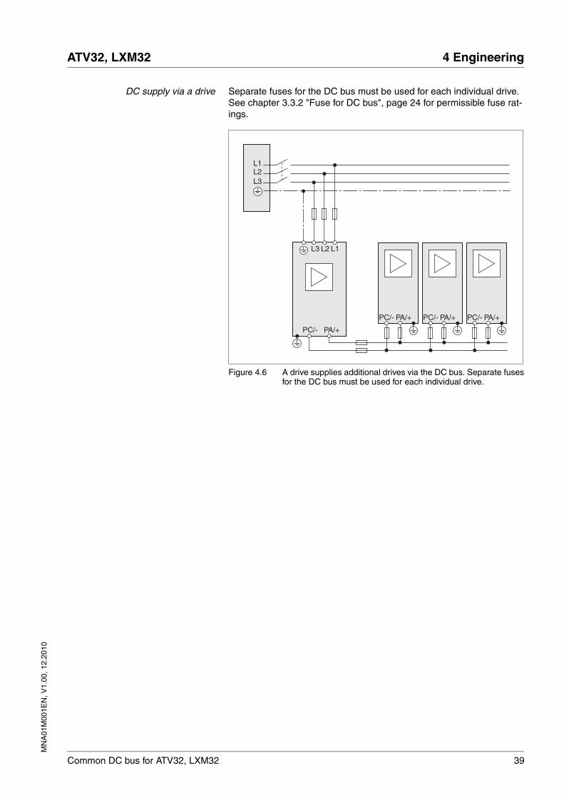
DC supply via a drive Separate fuses for the DC bus must be used for each individual drive. See chapter 3.3.2 "Fuse for DC bus", page 24 for permissible fuse rat-ings.
Figure 4.6 A drive supplies additional drives via the DC bus. Separate fusesfor the DC bus must be used for each individual drive.
L3L2L1
L2 L1L3
PC/- PA/+ PC/- PA/+ PC/- PA/+
PC/- PA/+
40 Common DC bus for ATV32, LXM32
4 Engineering ATV32, LXM32
MN
A01
M00
1EN
, V1.
00, 1
2.20
10
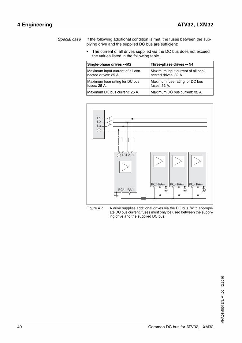
Special case If the following additional condition is met, the fuses between the sup-plying drive and the supplied DC bus are sufficient:
• The current of all drives supplied via the DC bus does not exceed the values listed in the following table.
Figure 4.7 A drive supplies additional drives via the DC bus. With appropri-ate DC bus current, fuses must only be used between the supply-ing drive and the supplied DC bus.
Single-phase drives ••M2 Three-phase drives ••N4
Maximum input current of all con-nected drives: 25 A.
Maximum input current of all con-nected drives: 32 A.
Maximum fuse rating for DC bus fuses: 25 A.
Maximum fuse rating for DC bus fuses: 32 A.
Maximum DC bus current: 25 A. Maximum DC bus current: 32 A.
L3L2L1
L2 L1L3
PC/- PA/+ PC/- PA/+ PC/- PA/+
PC/- PA/+
MN
A01
M00
1EN
, V1.
00, 1
2.20
10
ATV32, LXM32 4 Engineering
Common DC bus for ATV32, LXM32 41
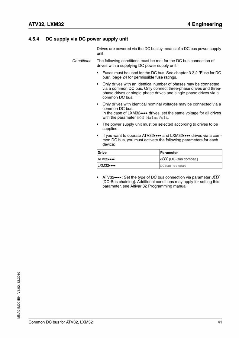
4.5.4 DC supply via DC power supply unit
Drives are powered via the DC bus by means of a DC bus power supply unit.
Conditions The following conditions must be met for the DC bus connection of drives with a supplying DC power supply unit:
• Fuses must be used for the DC bus. See chapter 3.3.2 "Fuse for DC bus", page 24 for permissible fuse ratings.
• Only drives with an identical number of phases may be connected via a common DC bus. Only connect three-phase drives and three-phase drives or single-phase drives and single-phase drives via a common DC bus.
• Only drives with identical nominal voltages may be connected via a common DC bus.In the case of LXM32•••• drives, set the same voltage for all drives with the parameter MON_MainsVolt.
• The power supply unit must be selected according to drives to be supplied.
• If you want to operate ATV32•••• and LXM32•••• drives via a com-mon DC bus, you must activate the following parameters for each device:
• ATV32••••: Set the type of DC bus connection via parameter dCCM [DC-Bus chaining]. Additional conditions may apply for setting this parameter, see Altivar 32 Programming manual.
Drive Parameter
ATV32•••• dCCC [DC-Bus compat.]
LXM32•••• DCbus_compat
42 Common DC bus for ATV32, LXM32
4 Engineering ATV32, LXM32
MN
A01
M00
1EN
, V1.
00, 1
2.20
10
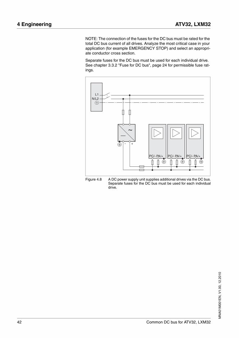
NOTE: The connection of the fuses for the DC bus must be rated for the total DC bus current of all drives. Analyze the most critical case in your application (for example EMERGENCY STOP) and select an appropri-ate conductor cross section.
Separate fuses for the DC bus must be used for each individual drive. See chapter 3.3.2 "Fuse for DC bus", page 24 for permissible fuse rat-ings.
Figure 4.8 A DC power supply unit supplies additional drives via the DC bus.Separate fuses for the DC bus must be used for each individualdrive.
N/L2L1
~
+-
PC/- PA/+ PC/- PA/+ PC/- PA/+
MN
A01
M00
1EN
, V1.
00, 1
2.20
10
ATV32, LXM32 4 Engineering
Common DC bus for ATV32, LXM32 43
4.6 Accessories for the common DC bus
4.6.1 Braking resistors
Excess energy in the common DC bus must be absorbed by the braking resistors. Depending on the application, one or more braking resistors can be connected. Consider the internal braking resistors of LXM32 drives in your calculations.
NOTE: If ATV32 drives and LXM32 drives are connected via the DC bus, the external braking resistors must be connected to the LXM32 drive with the greatest nominal power.
NOTE: If drives with a different nominal power are connected via the DC bus, you must connect braking resistors to the drive with the greatest nominal power. See the manual of the respective product for more infor-mation.
4.6.1.1 Rating the braking resistor
@ WARNINGMOTOR WITHOUT BRAKING EFFECT
An insufficient braking resistor causes overvoltage on the DC bus and switches off the power stage. The motor is no longer actively deceler-ated.
• Verify that the braking resistor has a sufficient rating.
• Check the parameter settings for the braking resistor.
• Check the I2t value under the most critical condition by perform-ing a test run. The device switches off at an I2t value of 100%.
• When performing the calculation and the test run, take into account the fact that the DC bus capacitors can absorb less brak-ing energy at higher mains voltages.
Failure to follow these instructions can result in death, serious injury or equipment damage.
@ WARNINGHOT SURFACES
The braking resistor may heat up to over 250°C (480°F) during oper-ation.
• Avoid contact with the hot braking resistor.
• Do not allow flammable or heat-sensitive parts in the immediate vicinity of the braking resistor.
• Provide for good heat dissipation.
• Check the temperature of the braking resistor under the most crit-ical condition by performing a test run.
Failure to follow these instructions can result in death, serious injury or equipment damage.
44 Common DC bus for ATV32, LXM32
4 Engineering ATV32, LXM32
MN
A01
M00
1EN
, V1.
00, 1
2.20
10
Braking resistors are required for dynamic applications. During deceler-ation, the kinetic energy is transformed into electrical energy in the mo-tor. The electrical energy increases the DC bus voltage. The braking resistor is activated when the defined threshold value is exceeded. The braking resistor transforms electrical energy into heat. If highly dynamic deceleration is required, the braking resistor must be well adapted to the system.
See also chapter 4.3 "Energy balance", page 30 for rating information.
LXM32: Internal braking resistor A braking resistor to absorb braking energy is integrated in LXM32 drives. The device is shipped with the internal braking resistor active.
If the braking energy of all drives sharing a common DC bus is greater than the energy the internal braking resistors can absorb, you must use an external braking resistor. Consider the most extreme case of your ap-plication in calculating the braking energy.Example: In the case of an EMERGENCY STOP, all drives decelerate si-multaneously; the braking resistors must be able to absorb the entire braking energy.
External braking resistor
An external braking resistor is required in applications in which the brak-ing energy is greater than the energy that can be absorbed by the drives sharing a common DC bus. Consider the most extreme case of your ap-plication in calculating the braking energy.Example: In the case of an EMERGENCY STOP, all drives decelerate si-multaneously; the braking resistors must be able to absorb the entire braking energy.
LXM32: Monitoring LXM32 drives monitor the power of the connected braking resistor. The load on the braking resistor can be read out.The connection of the external braking resistor is short-circuit protected. There is no protection in the case of a ground fault.
Further information on the subject Page
Technical data chapter 3.5 "Braking resistor" 27
Commissioning chapter 6.2 "LXM32: Setting the braking resis-tor parameters"
63
MN
A01
M00
1EN
, V1.
00, 1
2.20
10
ATV32, LXM32 4 Engineering
Common DC bus for ATV32, LXM32 45
Calculation of external brakingresistor
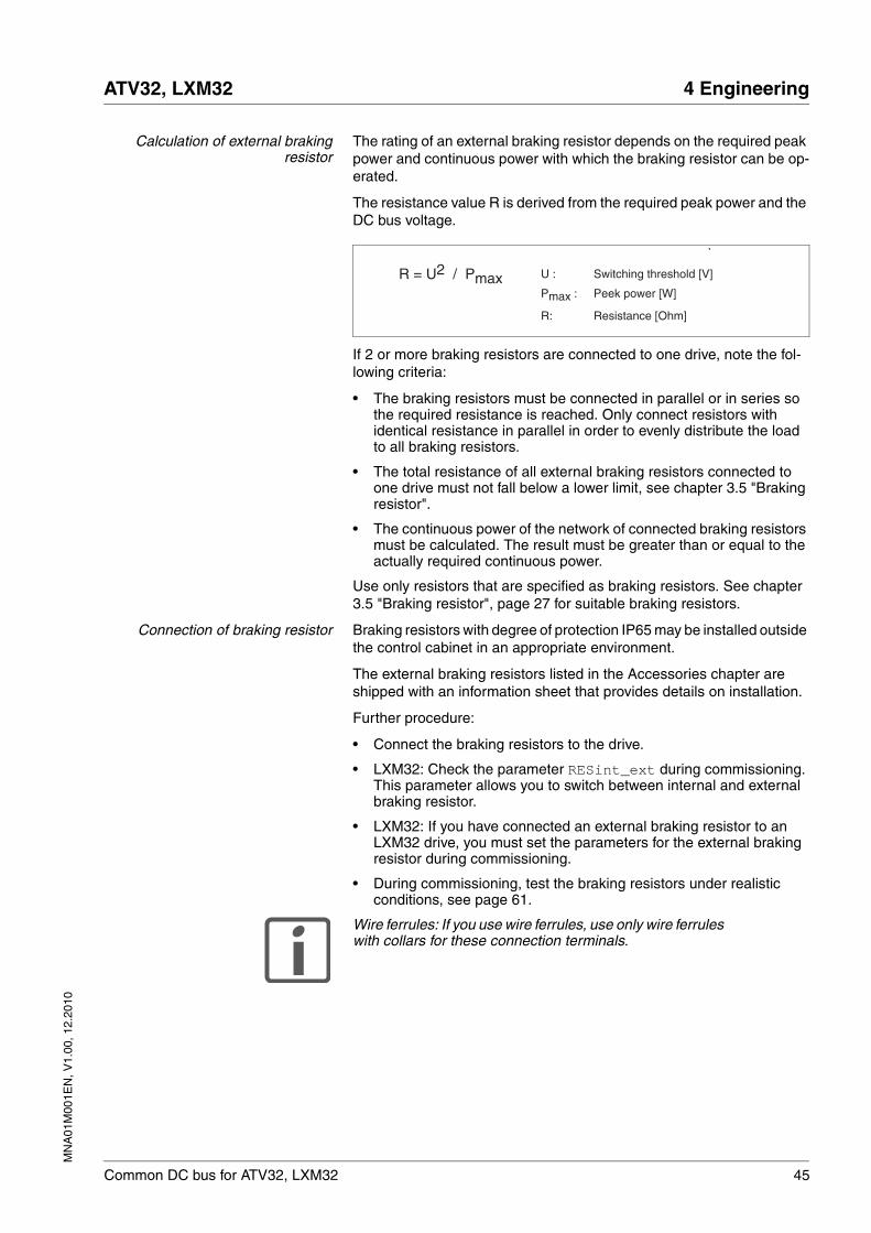
The rating of an external braking resistor depends on the required peak power and continuous power with which the braking resistor can be op-erated.
The resistance value R is derived from the required peak power and the DC bus voltage.
If 2 or more braking resistors are connected to one drive, note the fol-lowing criteria:
• The braking resistors must be connected in parallel or in series so the required resistance is reached. Only connect resistors with identical resistance in parallel in order to evenly distribute the load to all braking resistors.
• The total resistance of all external braking resistors connected to one drive must not fall below a lower limit, see chapter 3.5 "Braking resistor".
• The continuous power of the network of connected braking resistors must be calculated. The result must be greater than or equal to the actually required continuous power.
Use only resistors that are specified as braking resistors. See chapter 3.5 "Braking resistor", page 27 for suitable braking resistors.
Connection of braking resistor Braking resistors with degree of protection IP65 may be installed outside the control cabinet in an appropriate environment.
The external braking resistors listed in the Accessories chapter are shipped with an information sheet that provides details on installation.
Further procedure:
• Connect the braking resistors to the drive.
• LXM32: Check the parameter RESint_ext during commissioning. This parameter allows you to switch between internal and external braking resistor.
• LXM32: If you have connected an external braking resistor to an LXM32 drive, you must set the parameters for the external braking resistor during commissioning.
• During commissioning, test the braking resistors under realistic conditions, see page 61.
Wire ferrules: If you use wire ferrules, use only wire ferrules with collars for these connection terminals.
R = U2 / Pmax U : Switching threshold [V]
Pmax : Peek power [W]
R: Resistance [Ohm]
46 Common DC bus for ATV32, LXM32
4 Engineering ATV32, LXM32
MN
A01
M00
1EN
, V1.
00, 1
2.20
10
4.6.1.2 Rating information
To rate the braking resistor, calculate the proportion contributing to ab-sorbing braking energy.
An external braking resistor is required if the kinetic energy that must be absorbed exceeds the total of the internal proportions, including the in-ternal braking resistor.
The energy Evar is the square difference between the voltage before the deceleration process and the response threshold.
The voltage prior to the deceleration process depends on the mains volt-age. The energy absorption by the DC bus capacitors is lowest when the mains voltage is highest. In the calculation, use the values for the high-est mains voltage.
Energy absorption braking resistor Two characteristic values determine the energy absorption of the brak-ing resistor.
• The continuous power PPR is the amount of energy that can be con-tinuously absorbed without overloading the braking resistor.
• The maximum energy ECR limits the maximum short-term power that can be absorbed.
If the continuous power was exceeded for a specific time, the braking re-sistor must remain without load for a corresponding period.
The characteristic values PPR and ECR of the internal braking resistor can be found in chapter 3 "Technical Data".
See page 31 for information on assessing the electrical and mechanical losses.
Example: LXM32 drive Deceleration of a rotary motor with the following data:
• Initial speed of rotation: n = 4000 min-1
• Rotor inertia: JR = 4 kgcm2
• Load inertia: JL = 6 kgcm2
Calculation of the energy to be absorbed:
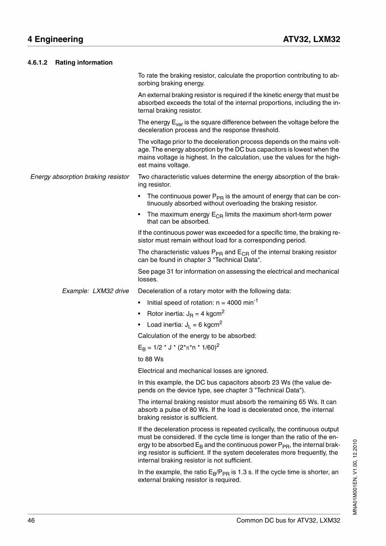
EB = 1/2 * J * (2*π*n * 1/60)2
to 88 Ws
Electrical and mechanical losses are ignored.
In this example, the DC bus capacitors absorb 23 Ws (the value de-pends on the device type, see chapter 3 "Technical Data").
The internal braking resistor must absorb the remaining 65 Ws. It can absorb a pulse of 80 Ws. If the load is decelerated once, the internal braking resistor is sufficient.
If the deceleration process is repeated cyclically, the continuous output must be considered. If the cycle time is longer than the ratio of the en-ergy to be absorbed EB and the continuous power PPR, the internal brak-ing resistor is sufficient. If the system decelerates more frequently, the internal braking resistor is not sufficient.
In the example, the ratio EB/PPR is 1.3 s. If the cycle time is shorter, an external braking resistor is required.
MN
A01
M00
1EN
, V1.
00, 1
2.20
10
ATV32, LXM32 4 Engineering
Common DC bus for ATV32, LXM32 47
Selecting an external brakingresistor
The selection is made in two steps:
• The maximum energy during deceleration must be less than the peak energy that the internal braking resistor can absorb: (EDi)<(ECr). In addition, the continuous power of the internal braking resistor must not be exceeded: (PC)<(PPr). If these conditions are met, then the internal braking resistor is sufficient.
• If one of the conditions is not met, you must use an external braking resistor. The braking resistor must be rated in such a way that the conditions are met. The resistance of the braking resistor must be between the specified minimum and maximum values, since other-wise the load can no longer be decelerated or the product might be destroyed.
See chapter 3.5 "Braking resistor", page 28 for technical data on the ex-ternal braking resistors.
48 Common DC bus for ATV32, LXM32
4 Engineering ATV32, LXM32
MN
A01
M00
1EN
, V1.
00, 1
2.20
10
4.6.2 Mains reactor
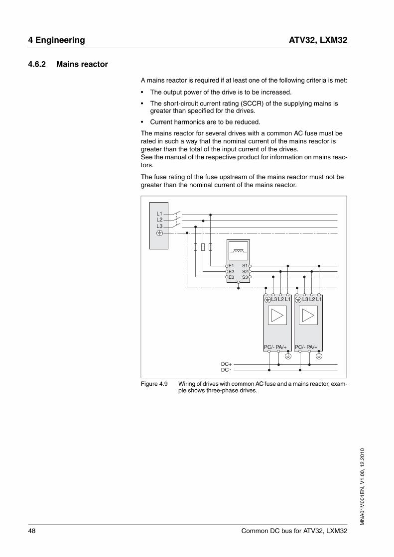
A mains reactor is required if at least one of the following criteria is met:
• The output power of the drive is to be increased.
• The short-circuit current rating (SCCR) of the supplying mains is greater than specified for the drives.
• Current harmonics are to be reduced.
The mains reactor for several drives with a common AC fuse must be rated in such a way that the nominal current of the mains reactor is greater than the total of the input current of the drives.See the manual of the respective product for information on mains reac-tors.
The fuse rating of the fuse upstream of the mains reactor must not be greater than the nominal current of the mains reactor.
Figure 4.9 Wiring of drives with common AC fuse and a mains reactor, exam-ple shows three-phase drives.
PC/- PA/+ PC/- PA/+
DC+DC -
L3L2L1
L2 L1L3 L2 L1L3
S2S3
S1
E3E2E1
MN
A01
M00
1EN
, V1.
00, 1
2.20
10
ATV32, LXM32 4 Engineering
Common DC bus for ATV32, LXM32 49
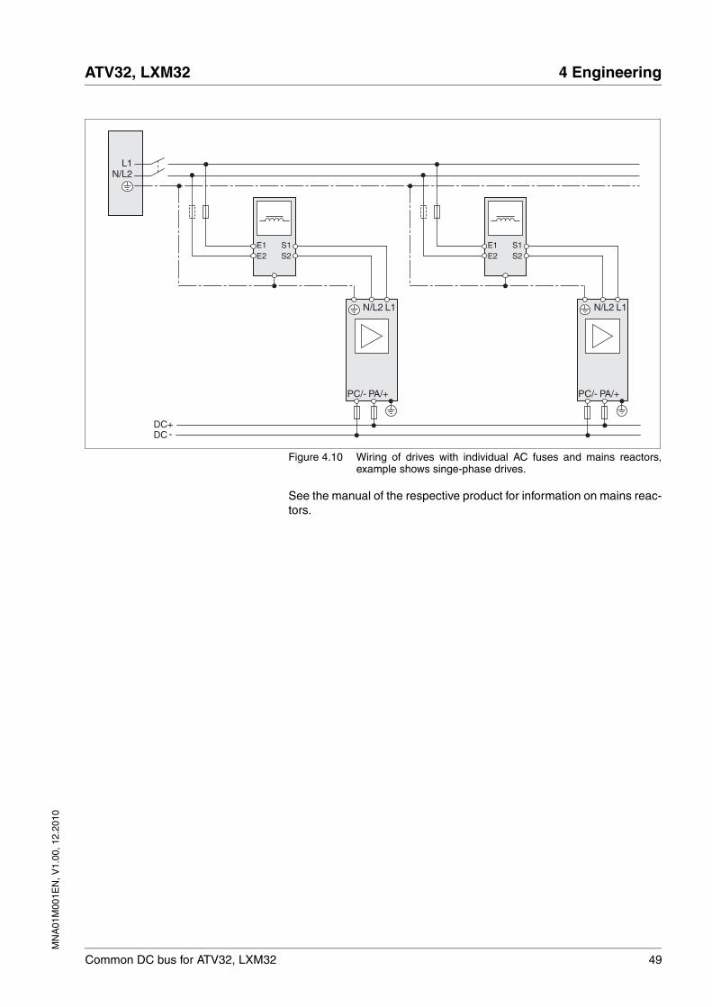
Figure 4.10 Wiring of drives with individual AC fuses and mains reactors,example shows singe-phase drives.
See the manual of the respective product for information on mains reac-tors.
N/L2L1
S2S1
E2E1
PC/- PA/+
DC+DC -
N/L2 L1
S2S1
E2E1
PC/- PA/+
N/L2 L1
50 Common DC bus for ATV32, LXM32
4 Engineering ATV32, LXM32
MN
A01
M00
1EN
, V1.
00, 1
2.20
10
4.6.3 External mains filter
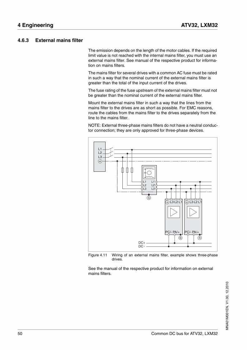
The emission depends on the length of the motor cables. If the required limit value is not reached with the internal mains filter, you must use an external mains filter. See manual of the respective product for informa-tion on mains filters.
The mains filter for several drives with a common AC fuse must be rated in such a way that the nominal current of the external mains filter is greater than the total of the input current of the drives.
The fuse rating of the fuse upstream of the external mains filter must not be greater than the nominal current of the external mains filter.
Mount the external mains filter in such a way that the lines from the mains filter to the drives are as short as possible. For EMC reasons, route the cables from the mains filter to the drives separately from the line to the mains filter.
NOTE: External three-phase mains filters do not have a neutral conduc-tor connection; they are only approved for three-phase devices.
Figure 4.11 Wiring of an external mains filter, example shows three-phasedrives.
See the manual of the respective product for information on external mains filters.
PC/- PA/+ PC/- PA/+
DC+DC -
L3L2L1
L2 L1L3 L2 L1L3
L3L2L1
L3'L2'L1'
MN
A01
M00
1EN
, V1.
00, 1
2.20
10
ATV32, LXM32 4 Engineering
Common DC bus for ATV32, LXM32 51
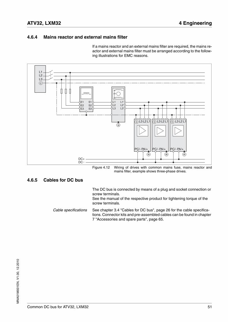
4.6.4 Mains reactor and external mains filter
If a mains reactor and an external mains filter are required, the mains re-actor and external mains filter must be arranged according to the follow-ing illustrations for EMC reasons.
Figure 4.12 Wiring of drives with common mains fuse, mains reactor andmains filter, example shows three-phase drives.
4.6.5 Cables for DC bus
The DC bus is connected by means of a plug and socket connection or screw terminals.See the manual of the respective product for tightening torque of the screw terminals.
Cable specifications See chapter 3.4 "Cables for DC bus", page 26 for the cable specifica-tions. Connector kits and pre-assembled cables can be found in chapter 7 "Accessories and spare parts", page 65.
PC/- PA/+ PC/- PA/+ PC/- PA/+
DC+DC -
L3L2L1
L2 L1L3 L2 L1L3
S2S3
S1
E3E2E1
L3L2L1
L3'L2'L1'
L2 L1L3

52 Common DC bus for ATV32, LXM32
4 Engineering ATV32, LXM32
MN
A01
M00
1EN
, V1.
00, 1
2.20
10
MN
A01
M00
1EN
, V1.
00, 1
2.20
10
ATV32, LXM32 5 Installation
Common DC bus for ATV32, LXM32 53
55 Installation
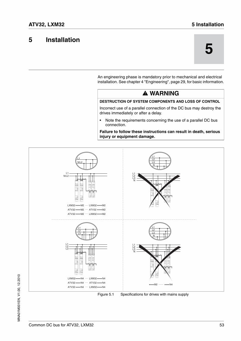
An engineering phase is mandatory prior to mechanical and electrical installation. See chapter 4 "Engineering", page 29, for basic information.
Figure 5.1 Specifications for drives with mains supply
@ WARNINGDESTRUCTION OF SYSTEM COMPONENTS AND LOSS OF CONTROL
Incorrect use of a parallel connection of the DC bus may destroy the drives immediately or after a delay.
• Note the requirements concerning the use of a parallel DC bus connection.
Failure to follow these instructions can result in death, serious injury or equipment damage.
L1
L3L2
L1
L3L2
L1
N/L2
L1
L3L2
N
L1N/L2
L1
L3L2
N
L1
L3L2
N
M2 ATV32 M2
LXM32 M2LXM32 M2
LXM32 M2M2ATV32
ATV32
LXM32 N4
ATV32ATV32
ATV32
LXM32
LXM32
N4
N4
N4
N4N4N4M2
L1
L3L2
N
54 Common DC bus for ATV32, LXM32
5 Installation ATV32, LXM32
MN
A01
M00
1EN
, V1.
00, 1
2.20
10
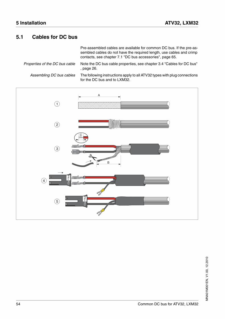
5.1 Cables for DC bus
Pre-assembled cables are available for common DC bus. If the pre-as-sembled cables do not have the required length, use cables and crimp contacts, see chapter 7.1 "DC bus accessories", page 65.
Properties of the DC bus cable Note the DC bus cable properties, see chapter 3.4 "Cables for DC bus" , page 26.
Assembling DC bus cables The following instructions apply to all ATV32 types with plug connections for the DC bus and to LXM32.
4
3
A
1
2
5
C
B
PC
/-P
A/+
PC
/-P
A/+

MN
A01
M00
1EN
, V1.
00, 1
2.20
10
ATV32, LXM32 5 Installation
Common DC bus for ATV32, LXM32 55
� (1) Strip the cable jacket, length A.
� (2) Slide back the shield braiding. Open the shield braiding and twist it to a shield connection.
� (3) Shorten the twisted shield connection to length B and insulate the shield braiding with heat shrink tube.Crimp the crimp contacts to the two stripped conductors. The strip-ping length is C. See chapter 7.1 "DC bus accessories", page 65 for information on the crimping tool.
� (4) Crimp a fork-type cable lug to the shield connection wire.Push the crimp contacts into the connector housing. Polarity: the red wire is PA/+, the black wire is PC/-.
� (5) Secure the shield with heat shrink tube.
Part Length in mm (inches)
A Cable jacket 130 (5.2)
B Length of shield connection 60 (2.5)
C Stripping length crimp contact 6 (0.25)
Diameter ring-type cable lug / fork-type cable lug
For M5 screw
56 Common DC bus for ATV32, LXM32
5 Installation ATV32, LXM32
MN
A01
M00
1EN
, V1.
00, 1
2.20
10
5.2 Wiring the DC bus
The DC bus is connected by means of a plug and socket connection or screw terminals.
Cable specifications See chapter 3.4 "Cables for DC bus", page 26 for the cable specifica-tions. Pre-assembled cables and connector kits can be found in chapter 7 "Accessories and spare parts", page 65.
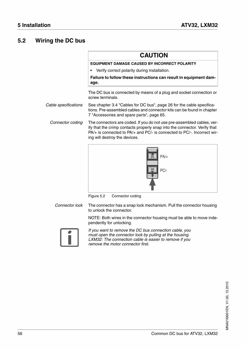
Connector coding The connectors are coded. If you do not use pre-assembled cables, ver-ify that the crimp contacts properly snap into the connector. Verify that PA/+ is connected to PA/+ and PC/- is connected to PC/-. Incorrect wir-ing will destroy the devices.
Figure 5.2 Connector coding
Connector lock The connector has a snap lock mechanism. Pull the connector housing to unlock the connector.
NOTE: Both wires in the connector housing must be able to move inde-pendently for unlocking.
If you want to remove the DC bus connection cable, you must open the connector lock by pulling at the housing. LXM32: The connection cable is easier to remove if you remove the motor connector first.
CAUTIONEQUIPMENT DAMAGE CAUSED BY INCORRECT POLARITY
• Verify correct polarity during installation.
Failure to follow these instructions can result in equipment dam-age.
PA/+
PC/-
MN
A01
M00
1EN
, V1.
00, 1
2.20
10
ATV32, LXM32 5 Installation
Common DC bus for ATV32, LXM32 57
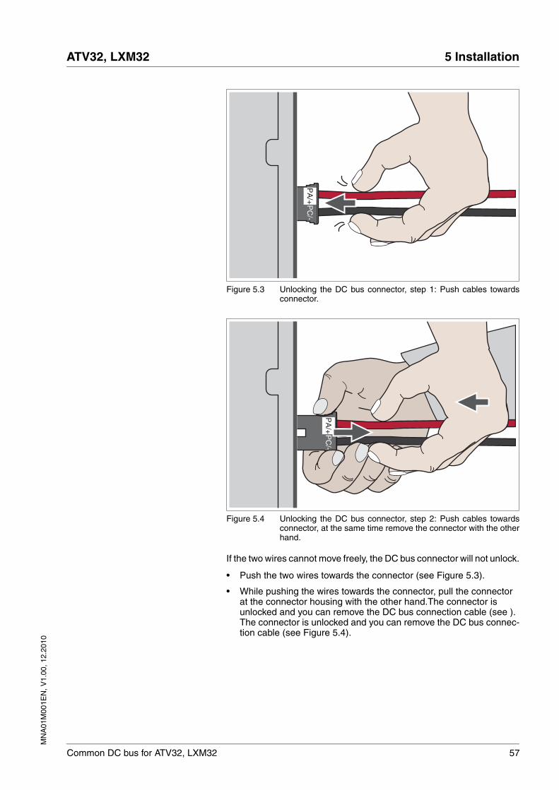
Figure 5.3 Unlocking the DC bus connector, step 1: Push cables towardsconnector.
Figure 5.4 Unlocking the DC bus connector, step 2: Push cables towardsconnector, at the same time remove the connector with the otherhand.
If the two wires cannot move freely, the DC bus connector will not unlock.
• Push the two wires towards the connector (see Figure 5.3).
• While pushing the wires towards the connector, pull the connector at the connector housing with the other hand.The connector is unlocked and you can remove the DC bus connection cable (see ). The connector is unlocked and you can remove the DC bus connec-tion cable (see Figure 5.4).
PC
/-P
A/+
PC
/-P
A/+
58 Common DC bus for ATV32, LXM32
5 Installation ATV32, LXM32
MN
A01
M00
1EN
, V1.
00, 1
2.20
10
5.2.1 Connecting the DC bus
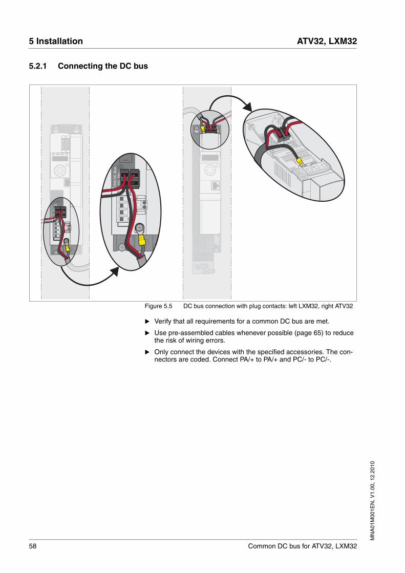
Figure 5.5 DC bus connection with plug contacts: left LXM32, right ATV32
� Verify that all requirements for a common DC bus are met.
� Use pre-assembled cables whenever possible (page 65) to reduce the risk of wiring errors.
� Only connect the devices with the specified accessories. The con-nectors are coded. Connect PA/+ to PA/+ and PC/- to PC/-.
CN
9 D
C B
usP
C/-
PA
/+
WV
U
ESC
CN
9 D
C B
usP
C/-
PA
/+
WV
U
ESC
MN
A01
M00
1EN
, V1.
00, 1
2.20
10
ATV32, LXM32 5 Installation
Common DC bus for ATV32, LXM32 59
5.3 Checking installation
� Verify that all requirements for a common DC bus are met. (Chapter 4.5 "Structure of a common DC bus")
� Verify that Y capacitors are activated (factory setting), see manual of the respective product.
� Verify that the wiring complies with the specifications as per chapter 4 "Engineering".
� Verify that the fuses used are correct. The maximum permissible fuse ratings must not be exceeded. See chapter 3.3.1 "Mains fuse", page 24 and chapter 3.3.2 "Fuse for DC bus", page 24 for the fuse ratings.
� Verify proper wiring. Verify that PA/+ is only connected to PA/+. Ver-ify that PC/- is only connected to PC/-.
� Verify that the shield is connected to a large surface area if you use shielded DC bus cables.
� Verify that the connector locks are properly snapped in.

60 Common DC bus for ATV32, LXM32
5 Installation ATV32, LXM32
MN
A01
M00
1EN
, V1.
00, 1
2.20
10
MN
A01
M00
1EN
, V1.
00, 1
2.20
10
ATV32, LXM32 6 Commissioning
Common DC bus for ATV32, LXM32 61
66 Commissioning
For commissioning, follow the commissioning instructions for the indi-vidual devices in the manual of the respective product.
@ WARNINGDESTRUCTION OF SYSTEM COMPONENTS AND LOSS OF CONTROL
Incorrect use of a parallel connection of the DC bus may destroy the drives immediately or after a delay.
• Note the requirements concerning the use of a parallel DC bus connection.
Failure to follow these instructions can result in death, serious injury or equipment damage.
62 Common DC bus for ATV32, LXM32
6 Commissioning ATV32, LXM32
MN
A01
M00
1EN
, V1.
00, 1
2.20
10
6.1 Commissioning procedure
Commissioning steps:
� Verify proper installation of the drives and the connections for the common DC bus, see chapter 5.3 "Checking installation", page 59.
� Switch on the controller supply voltage simultaneously for all devices since the braking resistor controller needs the controller supply voltage.
� Activate mains phase monitoring for the drives with mains supply.
� Verify that only drives with identical nominal voltages have been connected.LXM32: Set the same voltage for all LXM32•••• drives.
� If you want to operate ATV32•••• and LXM32•••• drives via a com-mon DC bus, you must activate the following parameters for each device:
� ATV32••••: Set the type of DC bus connection via parameter dCCM [DC-Bus chaining]. Additional conditions may apply for setting this parameter, see Altivar 32 programming manual.
� LXM32: Set the parameters for the braking resistors of LXM32•••• drives, see page 63.
� Commission the drives, see the descriptions in the manuals for the individual products.
Drive Parameter
LXM32 MON_MainsVolt
Drive Parameter
ATV32 dCCC [DC-Bus compat.]
LXM32 DCbus_compat
Drive Parameter
ATV32 dCCm [DC-Bus chaining]
Drive Parameter
LXM32 RESint_extRESext_PRESext_RRESext_ton
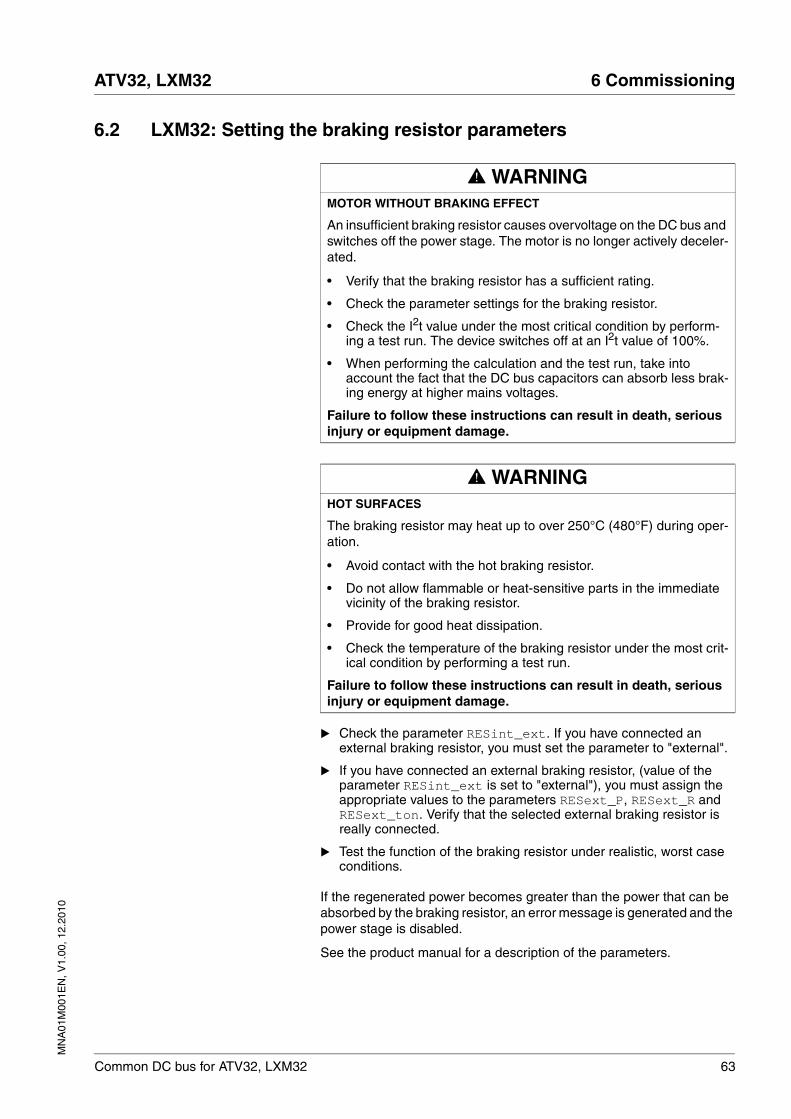
MN
A01
M00
1EN
, V1.
00, 1
2.20
10
ATV32, LXM32 6 Commissioning
Common DC bus for ATV32, LXM32 63
6.2 LXM32: Setting the braking resistor parameters
� Check the parameter RESint_ext. If you have connected an external braking resistor, you must set the parameter to "external".
� If you have connected an external braking resistor, (value of the parameter RESint_ext is set to "external"), you must assign the appropriate values to the parameters RESext_P, RESext_R and RESext_ton. Verify that the selected external braking resistor is really connected.
� Test the function of the braking resistor under realistic, worst case conditions.
If the regenerated power becomes greater than the power that can be absorbed by the braking resistor, an error message is generated and the power stage is disabled.
See the product manual for a description of the parameters.
@ WARNINGMOTOR WITHOUT BRAKING EFFECT
An insufficient braking resistor causes overvoltage on the DC bus and switches off the power stage. The motor is no longer actively deceler-ated.
• Verify that the braking resistor has a sufficient rating.
• Check the parameter settings for the braking resistor.
• Check the I2t value under the most critical condition by perform-ing a test run. The device switches off at an I2t value of 100%.
• When performing the calculation and the test run, take into account the fact that the DC bus capacitors can absorb less brak-ing energy at higher mains voltages.
Failure to follow these instructions can result in death, serious injury or equipment damage.
@ WARNINGHOT SURFACES
The braking resistor may heat up to over 250°C (480°F) during oper-ation.
• Avoid contact with the hot braking resistor.
• Do not allow flammable or heat-sensitive parts in the immediate vicinity of the braking resistor.
• Provide for good heat dissipation.
• Check the temperature of the braking resistor under the most crit-ical condition by performing a test run.
Failure to follow these instructions can result in death, serious injury or equipment damage.
64 Common DC bus for ATV32, LXM32
6 Commissioning ATV32, LXM32
MN
A01
M00
1EN
, V1.
00, 1
2.20
10
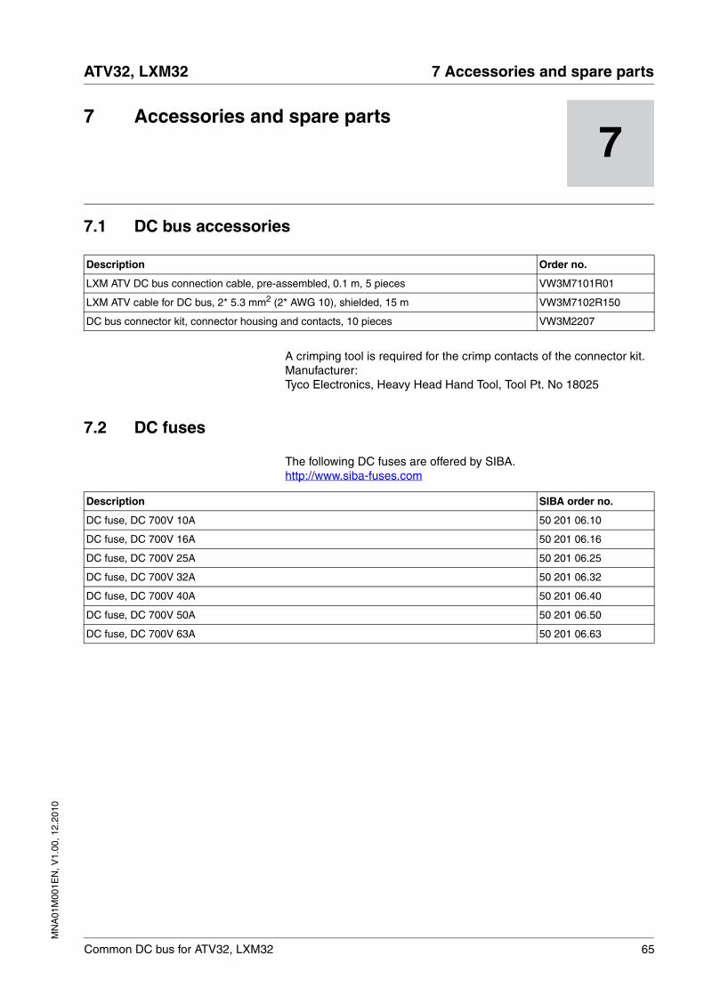
MN
A01
M00
1EN
, V1.
00, 1
2.20
10
ATV32, LXM32 7 Accessories and spare parts
Common DC bus for ATV32, LXM32 65
77 Accessories and spare parts
7.1 DC bus accessories
A crimping tool is required for the crimp contacts of the connector kit. Manufacturer:Tyco Electronics, Heavy Head Hand Tool, Tool Pt. No 18025
7.2 DC fuses
The following DC fuses are offered by SIBA.http://www.siba-fuses.com
Description Order no.
LXM ATV DC bus connection cable, pre-assembled, 0.1 m, 5 pieces VW3M7101R01
LXM ATV cable for DC bus, 2* 5.3 mm2 (2* AWG 10), shielded, 15 m VW3M7102R150
DC bus connector kit, connector housing and contacts, 10 pieces VW3M2207
Description SIBA order no.
DC fuse, DC 700V 10A 50 201 06.10
DC fuse, DC 700V 16A 50 201 06.16
DC fuse, DC 700V 25A 50 201 06.25
DC fuse, DC 700V 32A 50 201 06.32
DC fuse, DC 700V 40A 50 201 06.40
DC fuse, DC 700V 50A 50 201 06.50
DC fuse, DC 700V 63A 50 201 06.63
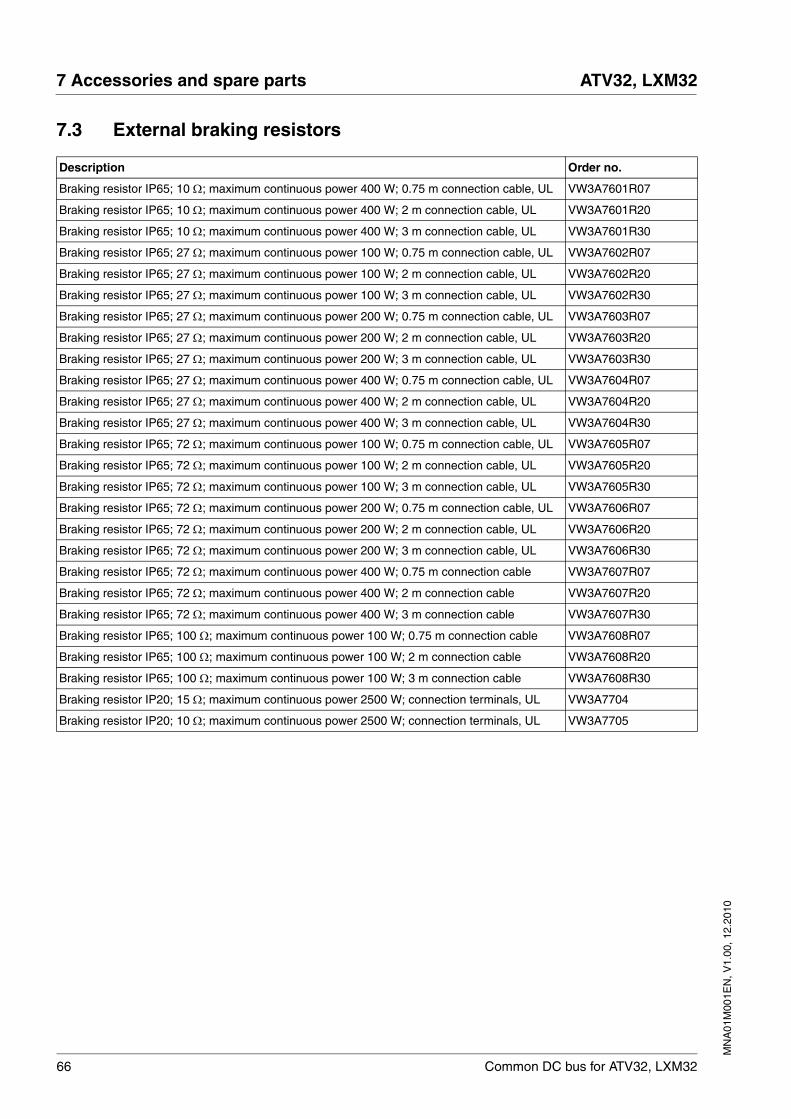
66 Common DC bus for ATV32, LXM32
7 Accessories and spare parts ATV32, LXM32
MN
A01
M00
1EN
, V1.
00, 1
2.20
10
7.3 External braking resistors
Description Order no.
Braking resistor IP65; 10 Ω; maximum continuous power 400 W; 0.75 m connection cable, UL VW3A7601R07
Braking resistor IP65; 10 Ω; maximum continuous power 400 W; 2 m connection cable, UL VW3A7601R20
Braking resistor IP65; 10 Ω; maximum continuous power 400 W; 3 m connection cable, UL VW3A7601R30
Braking resistor IP65; 27 Ω; maximum continuous power 100 W; 0.75 m connection cable, UL VW3A7602R07
Braking resistor IP65; 27 Ω; maximum continuous power 100 W; 2 m connection cable, UL VW3A7602R20
Braking resistor IP65; 27 Ω; maximum continuous power 100 W; 3 m connection cable, UL VW3A7602R30
Braking resistor IP65; 27 Ω; maximum continuous power 200 W; 0.75 m connection cable, UL VW3A7603R07
Braking resistor IP65; 27 Ω; maximum continuous power 200 W; 2 m connection cable, UL VW3A7603R20
Braking resistor IP65; 27 Ω; maximum continuous power 200 W; 3 m connection cable, UL VW3A7603R30
Braking resistor IP65; 27 Ω; maximum continuous power 400 W; 0.75 m connection cable, UL VW3A7604R07
Braking resistor IP65; 27 Ω; maximum continuous power 400 W; 2 m connection cable, UL VW3A7604R20
Braking resistor IP65; 27 Ω; maximum continuous power 400 W; 3 m connection cable, UL VW3A7604R30
Braking resistor IP65; 72 Ω; maximum continuous power 100 W; 0.75 m connection cable, UL VW3A7605R07
Braking resistor IP65; 72 Ω; maximum continuous power 100 W; 2 m connection cable, UL VW3A7605R20
Braking resistor IP65; 72 Ω; maximum continuous power 100 W; 3 m connection cable, UL VW3A7605R30
Braking resistor IP65; 72 Ω; maximum continuous power 200 W; 0.75 m connection cable, UL VW3A7606R07
Braking resistor IP65; 72 Ω; maximum continuous power 200 W; 2 m connection cable, UL VW3A7606R20
Braking resistor IP65; 72 Ω; maximum continuous power 200 W; 3 m connection cable, UL VW3A7606R30
Braking resistor IP65; 72 Ω; maximum continuous power 400 W; 0.75 m connection cable VW3A7607R07
Braking resistor IP65; 72 Ω; maximum continuous power 400 W; 2 m connection cable VW3A7607R20
Braking resistor IP65; 72 Ω; maximum continuous power 400 W; 3 m connection cable VW3A7607R30
Braking resistor IP65; 100 Ω; maximum continuous power 100 W; 0.75 m connection cable VW3A7608R07
Braking resistor IP65; 100 Ω; maximum continuous power 100 W; 2 m connection cable VW3A7608R20
Braking resistor IP65; 100 Ω; maximum continuous power 100 W; 3 m connection cable VW3A7608R30
Braking resistor IP20; 15 Ω; maximum continuous power 2500 W; connection terminals, UL VW3A7704
Braking resistor IP20; 10 Ω; maximum continuous power 2500 W; connection terminals, UL VW3A7705
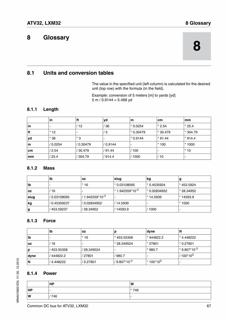
MN
A01
M00
1EN
, V1.
00, 1
2.20
10
ATV32, LXM32 8 Glossary
Common DC bus for ATV32, LXM32 67
88 Glossary
8.1 Units and conversion tables
The value in the specified unit (left column) is calculated for the desired unit (top row) with the formula (in the field).
Example: conversion of 5 meters [m] to yards [yd]5 m / 0.9144 = 5.468 yd
8.1.1 Length
8.1.2 Mass
8.1.3 Force
8.1.4 Power
in ft yd m cm mm
in - / 12 / 36 * 0.0254 * 2.54 * 25.4
ft * 12 - / 3 * 0.30479 * 30.479 * 304.79
yd * 36 * 3 - * 0.9144 * 91.44 * 914.4
m / 0.0254 / 0.30479 / 0.9144 - * 100 * 1000
cm / 2.54 / 30.479 / 91.44 / 100 - * 10
mm / 25.4 / 304.79 / 914.4 / 1000 / 10 -
lb oz slug kg g
lb - * 16 * 0.03108095 * 0.4535924 * 453.5924
oz / 16 - * 1.942559*10-3 * 0.02834952 * 28.34952
slug / 0.03108095 / 1.942559*10-3 - * 14.5939 * 14593.9
kg / 0.45359237 / 0.02834952 / 14.5939 - * 1000
g / 453.59237 / 28.34952 / 14593.9 / 1000 -
lb oz p dyne N
lb - * 16 * 453.55358 * 444822.2 * 4.448222
oz / 16 - * 28.349524 * 27801 * 0.27801
p / 453.55358 / 28.349524 - * 980.7 * 9.807*10-3
dyne / 444822.2 / 27801 / 980.7 - / 100*103
N / 4.448222 / 0.27801 / 9.807*10-3 * 100*103 -
HP W
HP - * 746
W / 746 -
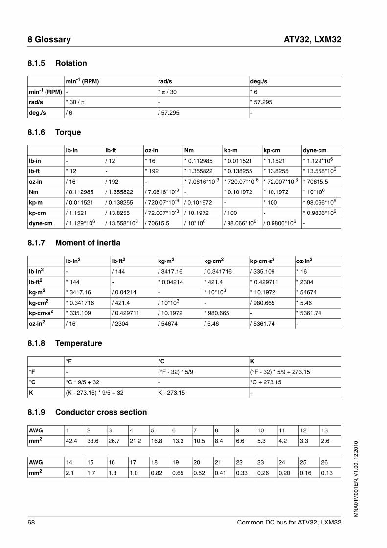
68 Common DC bus for ATV32, LXM32
8 Glossary ATV32, LXM32
MN
A01
M00
1EN
, V1.
00, 1
2.20
10
8.1.5 Rotation
8.1.6 Torque
8.1.7 Moment of inertia
8.1.8 Temperature
8.1.9 Conductor cross section
min-1 (RPM) rad/s deg./s
min-1 (RPM) - * π / 30 * 6
rad/s * 30 / π - * 57.295
deg./s / 6 / 57.295 -
lb·in lb·ft oz·in Nm kp·m kp·cm dyne·cm
lb·in - / 12 * 16 * 0.112985 * 0.011521 * 1.1521 * 1.129*106
lb·ft * 12 - * 192 * 1.355822 * 0.138255 * 13.8255 * 13.558*106
oz·in / 16 / 192 - * 7.0616*10-3 * 720.07*10-6 * 72.007*10-3 * 70615.5
Nm / 0.112985 / 1.355822 / 7.0616*10-3 - * 0.101972 * 10.1972 * 10*106
kp·m / 0.011521 / 0.138255 / 720.07*10-6 / 0.101972 - * 100 * 98.066*106
kp·cm / 1.1521 / 13.8255 / 72.007*10-3 / 10.1972 / 100 - * 0.9806*106
dyne·cm / 1.129*106 / 13.558*106 / 70615.5 / 10*106 / 98.066*106 / 0.9806*106 -
lb·in2 lb·ft2 kg·m2 kg·cm2 kp·cm·s2 oz·in2
lb·in2 - / 144 / 3417.16 / 0.341716 / 335.109 * 16
lb·ft2 * 144 - * 0.04214 * 421.4 * 0.429711 * 2304
kg·m2 * 3417.16 / 0.04214 - * 10*103 * 10.1972 * 54674
kg·cm2 * 0.341716 / 421.4 / 10*103 - / 980.665 * 5.46
kp·cm·s2 * 335.109 / 0.429711 / 10.1972 * 980.665 - * 5361.74
oz·in2 / 16 / 2304 / 54674 / 5.46 / 5361.74 -
°F °C K
°F - (°F - 32) * 5/9 (°F - 32) * 5/9 + 273.15
°C °C * 9/5 + 32 - °C + 273.15
K (K - 273.15) * 9/5 + 32 K - 273.15 -
AWG 1 2 3 4 5 6 7 8 9 10 11 12 13
mm2 42.4 33.6 26.7 21.2 16.8 13.3 10.5 8.4 6.6 5.3 4.2 3.3 2.6
AWG 14 15 16 17 18 19 20 21 22 23 24 25 26
mm2 2.1 1.7 1.3 1.0 0.82 0.65 0.52 0.41 0.33 0.26 0.20 0.16 0.13
MN
A01
M00
1EN
, V1.
00, 1
2.20
10
ATV32, LXM32 8 Glossary
Common DC bus for ATV32, LXM32 69
8.2 Terms and Abbreviations
See chapter 2.6 "Standards and terminology" for information on the per-tinent standards on which many terms are based. Some terms and ab-breviations may have specific meanings with regard to the standards.
AC Alternating current
DC Direct current
DC bus Circuit that supplies the power stage with energy (direct voltage).
Drive system System consisting of controller, power stage and motor.
EMC Electromagnetic compatibility
Error Discrepancy between a computed, observed or measured value or con-dition and the specified or theoretically correct value or condition.
Error class Classification of errors into groups. The different error classes allow for specific responses to errors, for example by severity.
Factory setting Factory settings when the product is shipped
Fault Fault is a state that can be caused by an error. Further information can be found in the pertinent standards such as IEC 61800-7, ODVA Com-mon Industrial Protocol (CIP).
Fault reset A function used to restore the drive to an operational state after a de-tected error is cleared by removing the cause of the error so that the er-ror is no longer active.
Parameter Device data and values that can be read and set (to a certain extent) by the user.
PELV Protective Extra Low Voltage, low voltage with isolation. For more infor-mation: IEC 60364-4-41
Persistent Indicates whether the value of the parameter remains in the memory af-ter the device is switched off.
Power stage The power stage controls the motor. The power stage generates current for controlling the motor on the basis of the positioning signals from the controller.
Quick Stop Function which can be used for fast deceleration of the motor via a com-mand or in the event of an error.
Warning If the term is used outside the context of safety instructions, a warning alerts to a potential problem that was detected by a monitoring function. A warning does not cause a transition of the operating state.
70 Common DC bus for ATV32, LXM32
8 Glossary ATV32, LXM32
MN
A01
M00
1EN
, V1.
00, 1
2.20
10
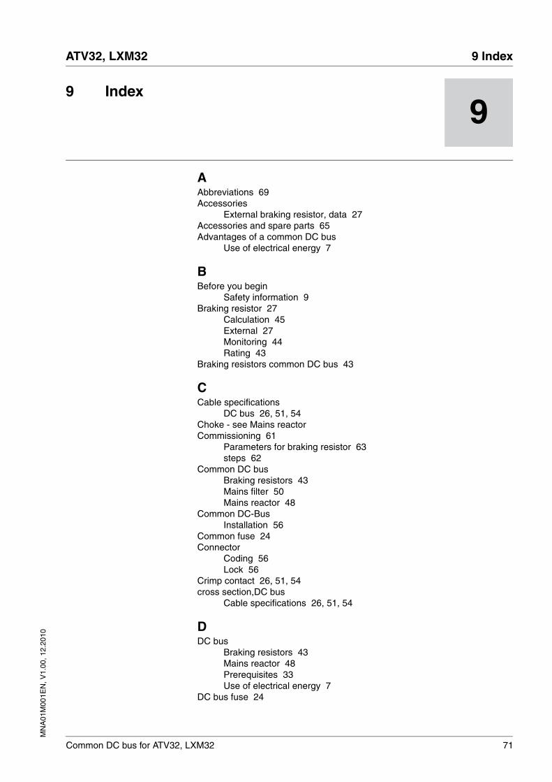
MN
A01
M00
1EN
, V1.
00, 1
2.20
10
ATV32, LXM32 9 Index
Common DC bus for ATV32, LXM32 71
99 Index
AAbbreviations 69Accessories
External braking resistor, data 27Accessories and spare parts 65Advantages of a common DC bus
Use of electrical energy 7
BBefore you begin
Safety information 9Braking resistor 27
Calculation 45External 27Monitoring 44Rating 43
Braking resistors common DC bus 43
CCable specifications
DC bus 26, 51, 54Choke - see Mains reactorCommissioning 61
Parameters for braking resistor 63steps 62
Common DC busBraking resistors 43Mains filter 50Mains reactor 48
Common DC-BusInstallation 56
Common fuse 24Connector
Coding 56Lock 56
Crimp contact 26, 51, 54cross section,DC bus
Cable specifications 26, 51, 54
DDC bus
Braking resistors 43Mains reactor 48Prerequisites 33Use of electrical energy 7
DC bus fuse 24
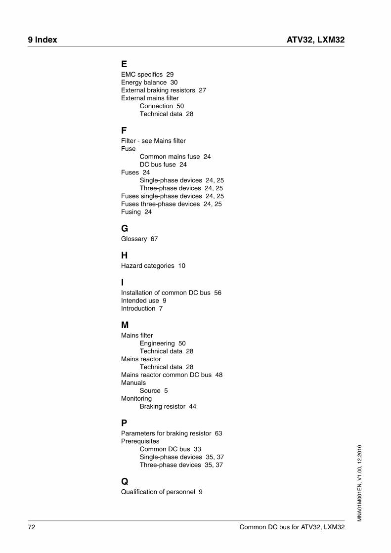
72 Common DC bus for ATV32, LXM32
9 Index ATV32, LXM32
MN
A01
M00
1EN
, V1.
00, 1
2.20
10
EEMC specifics 29Energy balance 30External braking resistors 27External mains filter
Connection 50Technical data 28
FFilter - see Mains filterFuse
Common mains fuse 24DC bus fuse 24
Fuses 24Single-phase devices 24, 25Three-phase devices 24, 25
Fuses single-phase devices 24, 25Fuses three-phase devices 24, 25Fusing 24
GGlossary 67
HHazard categories 10
IInstallation of common DC bus 56Intended use 9Introduction 7
MMains filter
Engineering 50Technical data 28
Mains reactorTechnical data 28
Mains reactor common DC bus 48Manuals
Source 5Monitoring
Braking resistor 44
PParameters for braking resistor 63Prerequisites
Common DC bus 33Single-phase devices 35, 37Three-phase devices 35, 37
QQualification of personnel 9
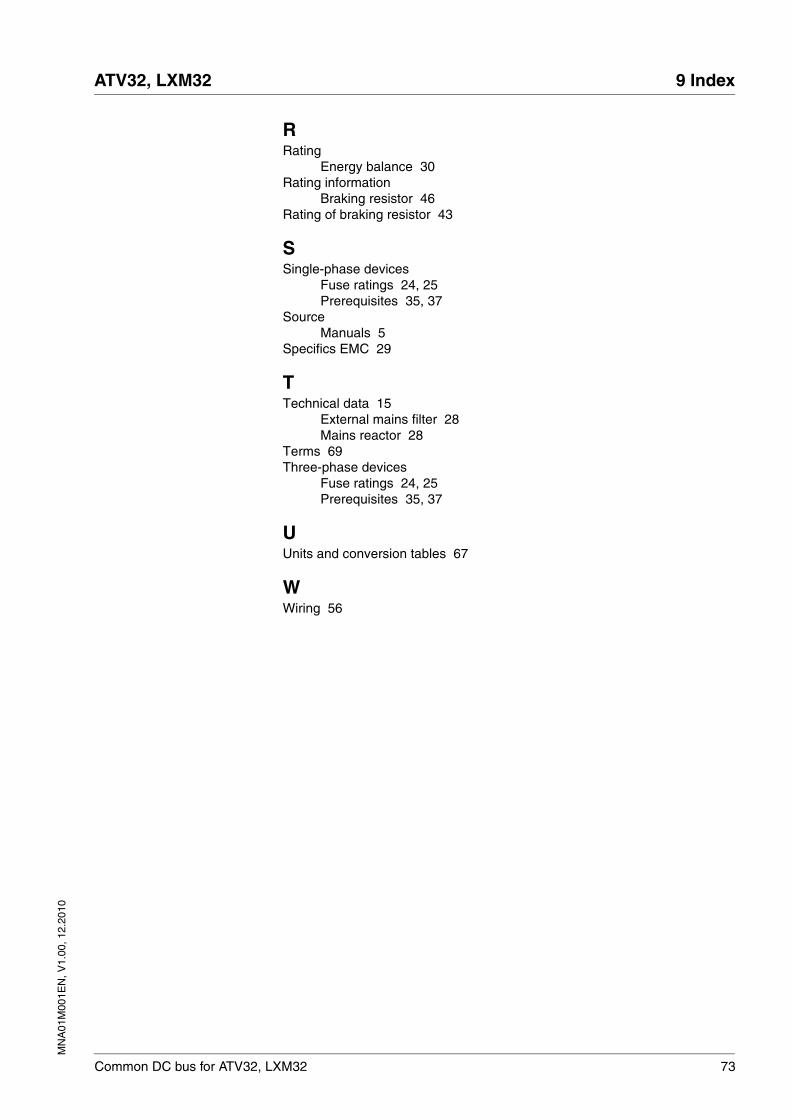
MN
A01
M00
1EN
, V1.
00, 1
2.20
10
ATV32, LXM32 9 Index
Common DC bus for ATV32, LXM32 73
RRating
Energy balance 30Rating information
Braking resistor 46Rating of braking resistor 43
SSingle-phase devices
Fuse ratings 24, 25Prerequisites 35, 37
SourceManuals 5
Specifics EMC 29
TTechnical data 15
External mains filter 28Mains reactor 28
Terms 69Three-phase devices
Fuse ratings 24, 25Prerequisites 35, 37
UUnits and conversion tables 67
WWiring 56
74 Common DC bus for ATV32, LXM32
9 Index ATV32, LXM32
MN
A01
M00
1EN
, V1.
00, 1
2.20
10