Embed Size (px)
Citation preview

0

IMPORTANT NOTICES
COPYRIGHTS
No part of this manual may be reproduced, stored in a retrieval system or
transmitted, in any form or by any means, electronic, mechanical, photocopying,
recording, or otherwise, without the prior written permission of Autel.
DISCLAIMER
All information, illustrations, and specifications in this manual are based on the
latest information available at the time of publication. Autel reserves the right to
make changes at any time without notice. Further, Autel shall not be liable for
errors contained herein or for incidental or consequential damages (including lost
profits).
All software screens shown in this manual are examples. Actual test screens vary
for each vehicle being tested.
TRADEMARKS
Autel®
, MaxiDAS®, MaxiScan
®, MaxiVideo
TM, MaxiRecorder
TM, MaxiTPMS
®,
MaxiSysTM
, and MaxiCheckTM
are trademarks of Autel Intelligent Technology
Co., Ltd, registered in China, the United States and other countries. All other
marks are trademarks or registered trademarks of their respective holders.
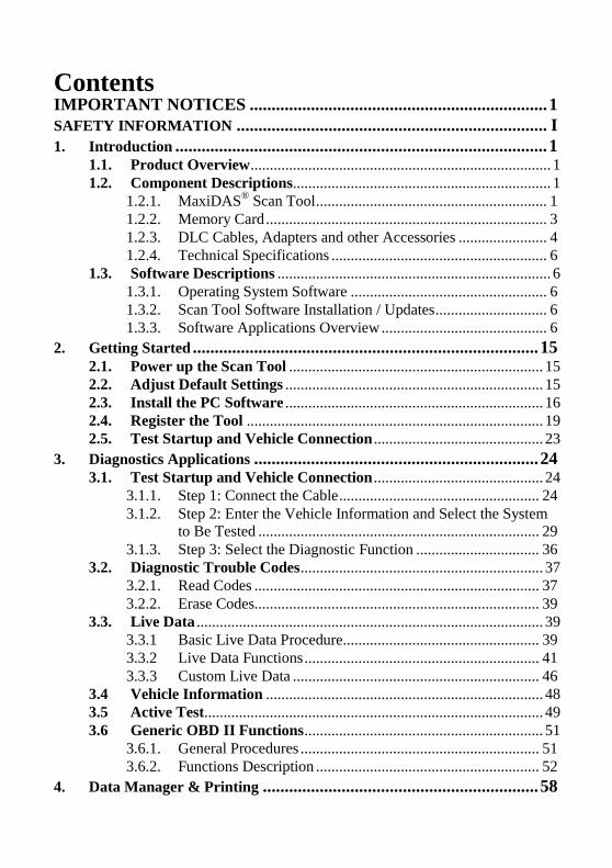
Contents IMPORTANT NOTICES .................................................................... 1 SAFETY INFORMATION ....................................................................... I 1. Introduction ..................................................................................... 1
1.1. Product Overview .............................................................................. 1 1.2. Component Descriptions ................................................................... 1
1.2.1. MaxiDAS® Scan Tool ............................................................ 1
1.2.2. Memory Card ......................................................................... 3 1.2.3. DLC Cables, Adapters and other Accessories ....................... 4 1.2.4. Technical Specifications ........................................................ 6
1.3. Software Descriptions ....................................................................... 6 1.3.1. Operating System Software ................................................... 6 1.3.2. Scan Tool Software Installation / Updates ............................. 6 1.3.3. Software Applications Overview ........................................... 6
2. Getting Started ............................................................................... 15 2.1. Power up the Scan Tool .................................................................. 15 2.2. Adjust Default Settings ................................................................... 15 2.3. Install the PC Software ................................................................... 16 2.4. Register the Tool ............................................................................. 19 2.5. Test Startup and Vehicle Connection ............................................ 23
3. Diagnostics Applications ................................................................. 24 3.1. Test Startup and Vehicle Connection ............................................ 24
3.1.1. Step 1: Connect the Cable .................................................... 24 3.1.2. Step 2: Enter the Vehicle Information and Select the System
to Be Tested ......................................................................... 29 3.1.3. Step 3: Select the Diagnostic Function ................................ 36
3.2. Diagnostic Trouble Codes ............................................................... 37 3.2.1. Read Codes .......................................................................... 37 3.2.2. Erase Codes.......................................................................... 39
3.3. Live Data .......................................................................................... 39 3.3.1 Basic Live Data Procedure ................................................... 39 3.3.2 Live Data Functions ............................................................. 41 3.3.3 Custom Live Data ................................................................ 46
3.4 Vehicle Information ........................................................................ 48 3.5 Active Test ........................................................................................ 49 3.6 Generic OBD II Functions .............................................................. 51
3.6.1. General Procedures .............................................................. 51 3.6.2. Functions Description .......................................................... 52
4. Data Manager & Printing ............................................................... 58
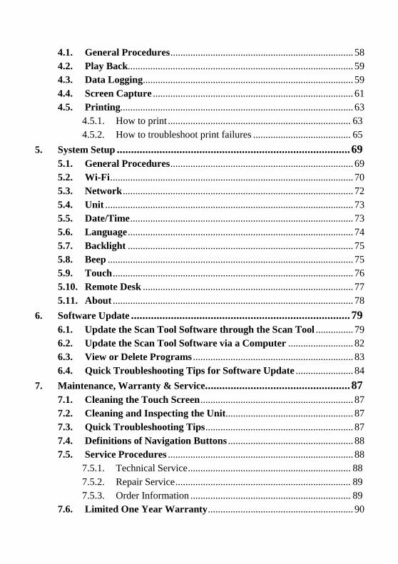
4.1. General Procedures ......................................................................... 58
4.2. Play Back.......................................................................................... 59
4.3. Data Logging .................................................................................... 59
4.4. Screen Capture ................................................................................ 61
4.5. Printing............................................................................................. 63
4.5.1. How to print ......................................................................... 63
4.5.2. How to troubleshoot print failures ....................................... 65
5. System Setup .................................................................................. 69 5.1. General Procedures ......................................................................... 69
5.2. Wi-Fi ................................................................................................. 70
5.3. Network ............................................................................................ 72
5.4. Unit ................................................................................................... 73
5.5. Date/Time ......................................................................................... 73
5.6. Language .......................................................................................... 74
5.7. Backlight .......................................................................................... 75
5.8. Beep .................................................................................................. 75
5.9. Touch ................................................................................................ 76
5.10. Remote Desk .................................................................................... 77
5.11. About ................................................................................................ 78
6. Software Update ............................................................................. 79 6.1. Update the Scan Tool Software through the Scan Tool ............... 79
6.2. Update the Scan Tool Software via a Computer .......................... 82
6.3. View or Delete Programs ................................................................ 83
6.4. Quick Troubleshooting Tips for Software Update ....................... 84
7. Maintenance, Warranty & Service................................................... 87 7.1. Cleaning the Touch Screen ............................................................. 87
7.2. Cleaning and Inspecting the Unit................................................... 87
7.3. Quick Troubleshooting Tips ........................................................... 87
7.4. Definitions of Navigation Buttons .................................................. 88
7.5. Service Procedures .......................................................................... 88
7.5.1. Technical Service ................................................................. 88
7.5.2. Repair Service ...................................................................... 89
7.5.3. Order Information ................................................................ 89
7.6. Limited One Year Warranty .......................................................... 90

I
SAFETY INFORMATION
DANGER: When an engine is operating, keep the service area WELL
VENTILATED or attach a building exhaust removal system to the engine exhaust
system. Engines produce carbon monoxide, an odorless, poisonous gas that
causes slower reaction time and can lead to serious personal injury or loss of life.
SAFETY DEFINITIONS
Follow all DANGER, WARNING, IMPORTANT, and NOTE messages in this
manual. These safety messages are defined as follows:
DANGER or WARNING: Means you risk bodily harm and /or possible
loss of life.
IMPORTANT: Means the information demands special attention or that you
risk damage to the vehicle or the tool.
NOTE: Provides clarity and helpful tips.
WARNINGS AND IMPORTANTS:
The safety messages cover situations Autel is aware of. Autel cannot know, evaluate or advise you as to all of the possible hazards. You must be certain that any conditions or service procedures encountered do not jeopardize your personal safety.
Always perform automotive testing in a safe environment.
Wear safety eye protection that meets ANSI standards.
Keep clothing, hair, hands, tools, test equipment, etc. away from all moving
or hot engine parts.
Operate the vehicle in a well ventilated work area: Exhaust gases are
poisonous.
Put the transmission in PARK (for automatic transmission) or NEUTRAL
(for manual transmission) and make sure the parking brake is engaged.

Put blocks in front of the drive wheels and never leave the vehicle
unattended while running tests.
Use extreme caution when working around the ignition coil, distributor cap,
ignition wires and spark plugs. These components create hazardous voltages
when the engine is running.
Keep a fire extinguisher suitable for gasoline/ chemical/ electrical fires
nearby.
Don’t connect or disconnect any test equipment while the ignition is on or
the engine is running.
Keep the scan tool dry, clean, free from oil/water or grease. Use a mild
detergent on a clean cloth to clean the outside of the scan tool, when
necessary.
Do not drive the vehicle and operate the scan tool at the same time. Any
distractions may cause an accident.
Refer to the service manual for the vehicle being serviced and adhere to all
diagnostic procedures and precautions. Failure to do so could result in
personal injury or otherwise unneeded repair.
To avoid damaging the scan tool or generating false data, make sure the
vehicle battery is fully charged and the connection to the vehicle DLC is
clean and secure.
Do not place the scan tool on the distributor of a vehicle. Strong
electro-magnetic interference can damage the scan tool.
1
1. Introduction
1.1. Product Overview
The MaxiDAS® Diagnostic System is the easiest-to-use scan tool which
features simple touch screen navigation. It is ingeniously designed to create
the functionality of the OEM tools used by automotive manufacturer’s
dealers, empowering independent garages to provide comprehensive
servicing in their own workshops without relying on dealer availability.
MaxiDAS® has a memory card that contains the operating system and scan
software applications. It can help you diagnose symptoms, codes, and
complaints quickly and efficiently by reading diagnostic trouble codes, and
viewing live data stream, freeze frame data, and vehicle information from
the vehicle’s ECUs. It can also perform such special functions as actuation
tests, immobilizer key coding and adaptation on the vehicle. You can save
recorded data readings, capture an image of the current screen and print
information.
1.2. Component Descriptions
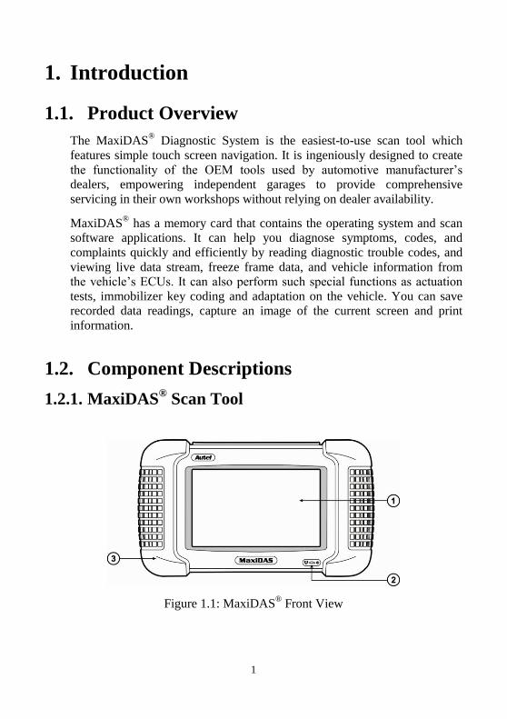
1.2.1. MaxiDAS® Scan Tool
Figure 1.1: MaxiDAS® Front View
2
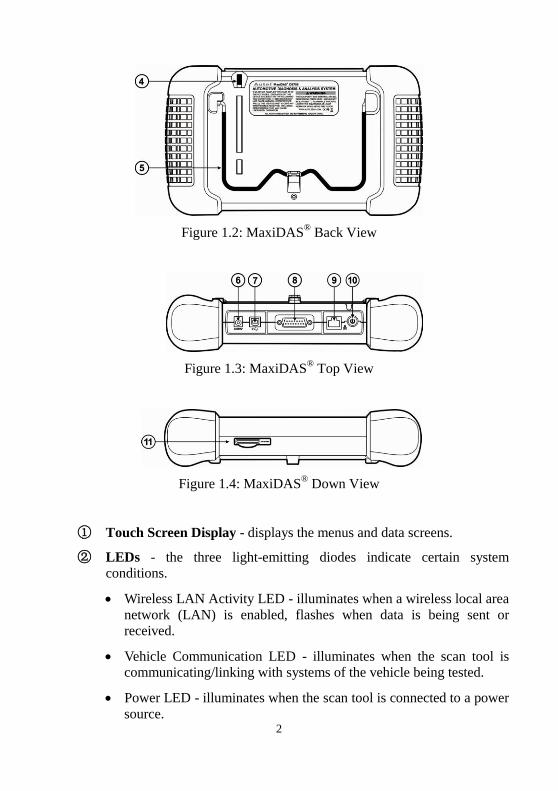
Figure 1.2: MaxiDAS® Back View
Figure 1.3: MaxiDAS® Top View
Figure 1.4: MaxiDAS® Down View
① Touch Screen Display - displays the menus and data screens.
② LEDs - the three light-emitting diodes indicate certain system
conditions.
Wireless LAN Activity LED - illuminates when a wireless local area
network (LAN) is enabled, flashes when data is being sent or
received.
Vehicle Communication LED - illuminates when the scan tool is
communicating/linking with systems of the vehicle being tested.
Power LED - illuminates when the scan tool is connected to a power
source.
3
③ Rubber Boot - protects the scan tool from accidental damage if
dropped.
④ Stylus Pen - selects items and enters information.
⑤ Stand - flips out for setting the scan tool in an upright position.
⑥ External DC Power Port - connects the 12 volt power adapter to
power the tool for updating, printing, Internet access, and etc. when
disconnected from the vehicle.
⑦ USB (universal serial bus) Port - connects peripheral devices such as
printers, and portable USB Drives.
⑧ DB15-Pin Port - connects the vehicle DLC cable.
⑨ RS 232 Serial Port - connects the PC serial cable.
⑩ On / Off Button - turns the scan tool on and off.
NOTE: No internal battery power is provided with this scan tool.
○11 SD Card Slot - holds the System SD Card.
NOTE: Do not remove memory card from the scan tool unless performing software updates to card.
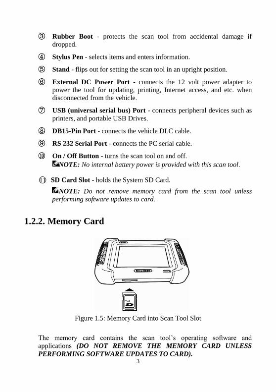
1.2.2. Memory Card
Figure 1.5: Memory Card into Scan Tool Slot
The memory card contains the scan tool’s operating software and
applications (DO NOT REMOVE THE MEMORY CARD UNLESS
PERFORMING SOFTWARE UPDATES TO CARD).
4
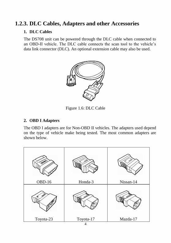
1.2.3. DLC Cables, Adapters and other Accessories
1. DLC Cables
The DS708 unit can be powered through the DLC cable when connected to
an OBD-II vehicle. The DLC cable connects the scan tool to the vehicle’s
data link connector (DLC). An optional extension cable may also be used.
Figure 1.6: DLC Cable
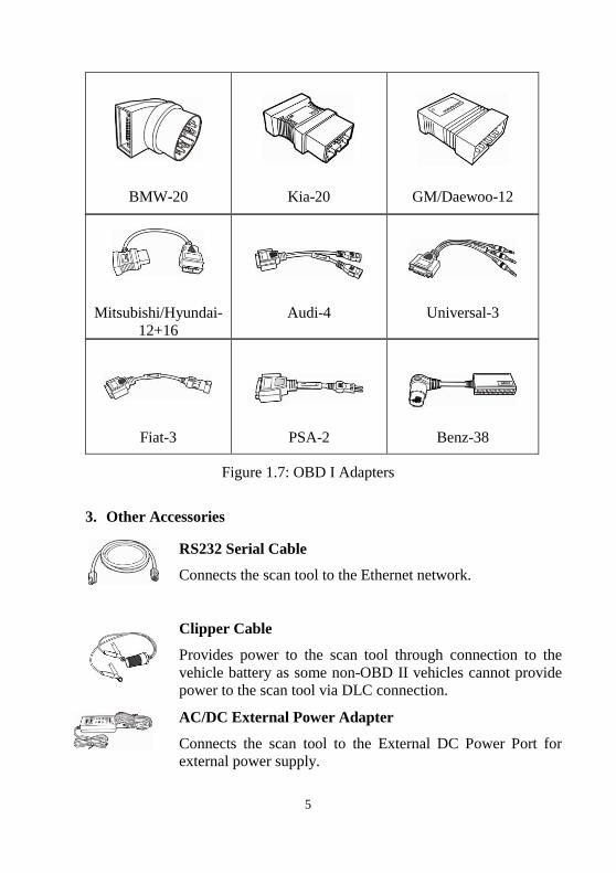
2. OBD I Adapters
The OBD I adapters are for Non-OBD II vehicles. The adapters used depend
on the type of vehicle make being tested. The most common adapters are
shown below.
OBD-16
Honda-3
Nissan-14
Toyota-23
Toyota-17
Mazda-17
5
BMW-20
Kia-20
GM/Daewoo-12
Mitsubishi/Hyundai-
12+16
Audi-4
Universal-3
Fiat-3
PSA-2
Benz-38
Figure 1.7: OBD I Adapters
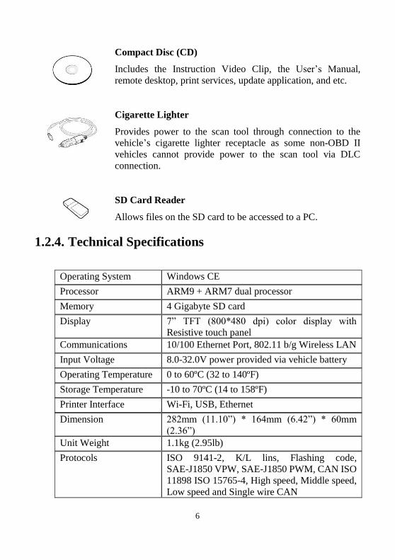
3. Other Accessories
RS232 Serial Cable
Connects the scan tool to the Ethernet network.
Clipper Cable
Provides power to the scan tool through connection to the
vehicle battery as some non-OBD II vehicles cannot provide
power to the scan tool via DLC connection.
AC/DC External Power Adapter
Connects the scan tool to the External DC Power Port for
external power supply.
6
Compact Disc (CD)
Includes the Instruction Video Clip, the User’s Manual,
remote desktop, print services, update application, and etc.
Cigarette Lighter
Provides power to the scan tool through connection to the
vehicle’s cigarette lighter receptacle as some non-OBD II
vehicles cannot provide power to the scan tool via DLC
connection.
SD Card Reader
Allows files on the SD card to be accessed to a PC.
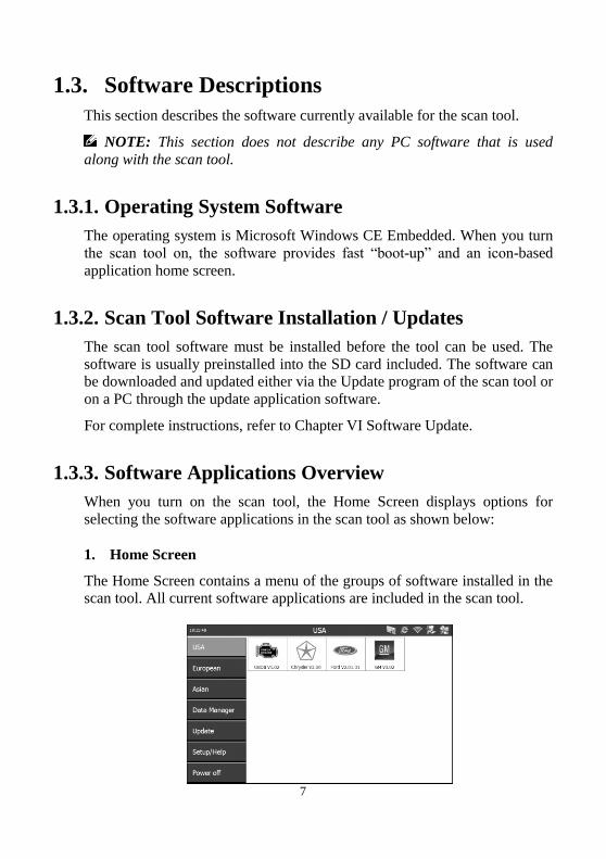
1.2.4. Technical Specifications
Operating System Windows CE
Processor ARM9 + ARM7 dual processor
Memory 4 Gigabyte SD card
Display 7” TFT (800*480 dpi) color display with
Resistive touch panel
Communications 10/100 Ethernet Port, 802.11 b/g Wireless LAN
Input Voltage 8.0-32.0V power provided via vehicle battery
Operating Temperature 0 to 60ºC (32 to 140ºF)
Storage Temperature -10 to 70ºC (14 to 158ºF)
Printer Interface Wi-Fi, USB, Ethernet
Dimension 282mm (11.10”) * 164mm (6.42”) * 60mm
(2.36”)
Unit Weight 1.1kg (2.95lb)
Protocols ISO 9141-2, K/L lins, Flashing code, SAE-J1850 VPW, SAE-J1850 PWM, CAN ISO
11898 ISO 15765-4, High speed, Middle speed,
Low speed and Single wire CAN
7
1.3. Software Descriptions
This section describes the software currently available for the scan tool.
NOTE: This section does not describe any PC software that is used
along with the scan tool.
1.3.1. Operating System Software
The operating system is Microsoft Windows CE Embedded. When you turn
the scan tool on, the software provides fast “boot-up” and an icon-based
application home screen.
1.3.2. Scan Tool Software Installation / Updates
The scan tool software must be installed before the tool can be used. The
software is usually preinstalled into the SD card included. The software can
be downloaded and updated either via the Update program of the scan tool or
on a PC through the update application software.
For complete instructions, refer to Chapter VI Software Update.
1.3.3. Software Applications Overview
When you turn on the scan tool, the Home Screen displays options for
selecting the software applications in the scan tool as shown below:
1. Home Screen
The Home Screen contains a menu of the groups of software installed in the
scan tool. All current software applications are included in the scan tool.
8
Figure 1.8: Home Screen
With the Home Screen displayed, you use either the stylus pen or a finger to
select an option to display the icons to choose. The options on the Home
Screen are described in the next few sections as follows:
USA
European
Asian
Data Manager
Update
Setup/Help
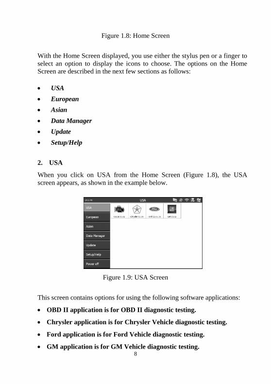
2. USA
When you click on USA from the Home Screen (Figure 1.8), the USA
screen appears, as shown in the example below.
Figure 1.9: USA Screen
This screen contains options for using the following software applications:
OBD II application is for OBD II diagnostic testing.
Chrysler application is for Chrysler Vehicle diagnostic testing.
Ford application is for Ford Vehicle diagnostic testing.
GM application is for GM Vehicle diagnostic testing.
9
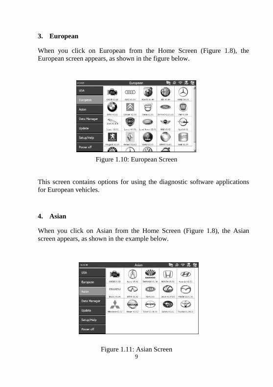
3. European
When you click on European from the Home Screen (Figure 1.8), the
European screen appears, as shown in the figure below.
Figure 1.10: European Screen
This screen contains options for using the diagnostic software applications
for European vehicles.
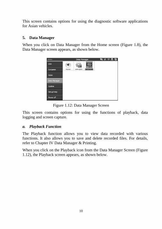
4. Asian
When you click on Asian from the Home Screen (Figure 1.8), the Asian
screen appears, as shown in the example below.
Figure 1.11: Asian Screen
10
This screen contains options for using the diagnostic software applications
for Asian vehicles.
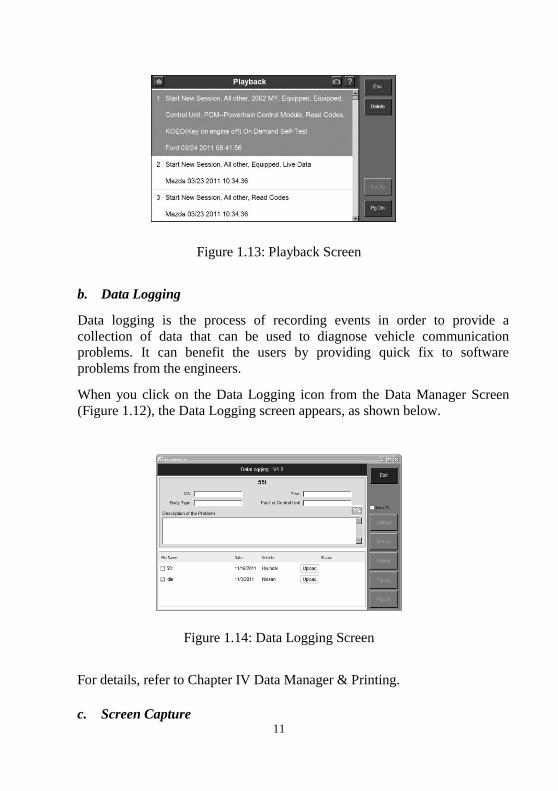
5. Data Manager
When you click on Data Manager from the Home screen (Figure 1.8), the
Data Manager screen appears, as shown below.
Figure 1.12: Data Manager Screen
This screen contains options for using the functions of playback, data
logging and screen capture.
a. Playback Function
The Playback function allows you to view data recorded with various
functions. It also allows you to save and delete recorded files. For details,
refer to Chapter IV Data Manager & Printing.
When you click on the Playback icon from the Data Manager Screen (Figure
1.12), the Playback screen appears, as shown below.
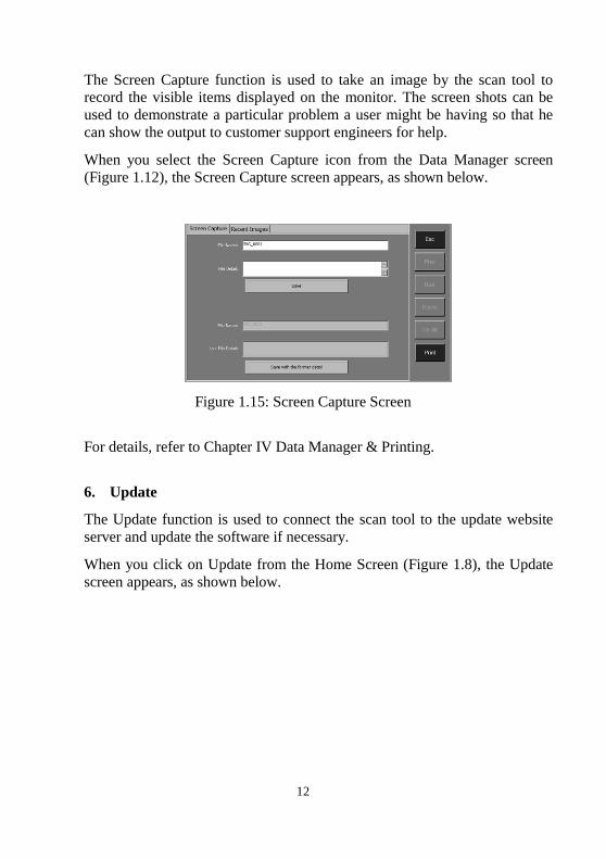
11
Figure 1.13: Playback Screen
b. Data Logging
Data logging is the process of recording events in order to provide a
collection of data that can be used to diagnose vehicle communication
problems. It can benefit the users by providing quick fix to software
problems from the engineers.
When you click on the Data Logging icon from the Data Manager Screen
(Figure 1.12), the Data Logging screen appears, as shown below.
Figure 1.14: Data Logging Screen
For details, refer to Chapter IV Data Manager & Printing.
c. Screen Capture
12
The Screen Capture function is used to take an image by the scan tool to
record the visible items displayed on the monitor. The screen shots can be
used to demonstrate a particular problem a user might be having so that he
can show the output to customer support engineers for help.
When you select the Screen Capture icon from the Data Manager screen
(Figure 1.12), the Screen Capture screen appears, as shown below.
Figure 1.15: Screen Capture Screen
For details, refer to Chapter IV Data Manager & Printing.
6. Update
The Update function is used to connect the scan tool to the update website
server and update the software if necessary.
When you click on Update from the Home Screen (Figure 1.8), the Update
screen appears, as shown below.
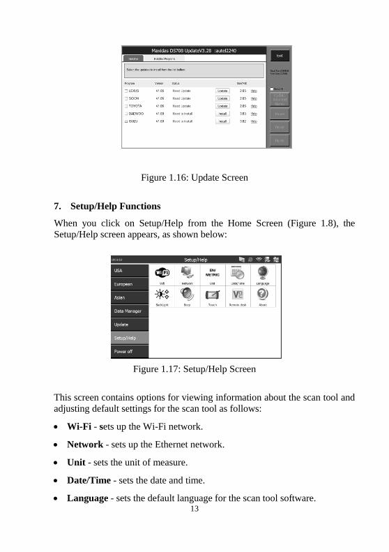
13
Figure 1.16: Update Screen
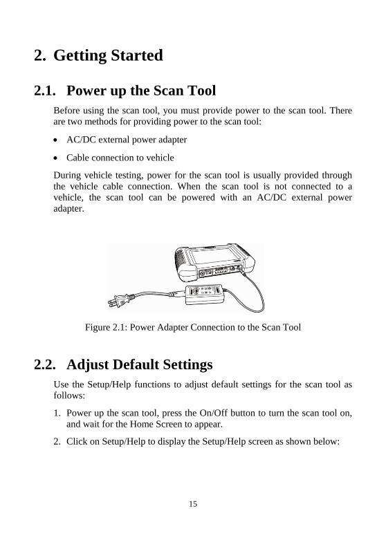
7. Setup/Help Functions
When you click on Setup/Help from the Home Screen (Figure 1.8), the
Setup/Help screen appears, as shown below:
Figure 1.17: Setup/Help Screen
This screen contains options for viewing information about the scan tool and
adjusting default settings for the scan tool as follows:
Wi-Fi - sets up the Wi-Fi network.
Network - sets up the Ethernet network.
Unit - sets the unit of measure.
Date/Time - sets the date and time.
Language - sets the default language for the scan tool software.

14
Backlight - adjusts the backlight of the screen.
Beep - sets the beep of the scan tool.
Touch - calibrates the touch screen.
Remote Desk - sets the remote desk.
About - provides information about the scan tool, such as software
version, operating system software version, hardware version, product
serial No., etc.
For more information, refer to Chapter V System Setup.
15
2. Getting Started
2.1. Power up the Scan Tool
Before using the scan tool, you must provide power to the scan tool. There
are two methods for providing power to the scan tool:
AC/DC external power adapter
Cable connection to vehicle
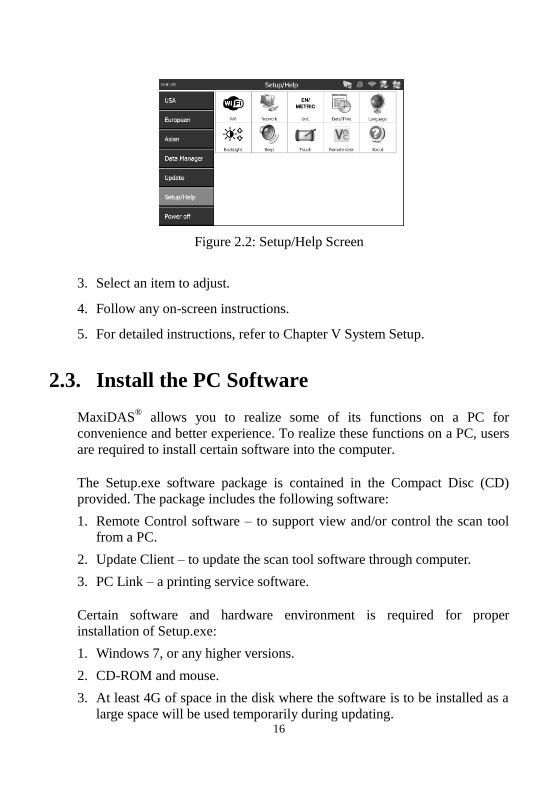
During vehicle testing, power for the scan tool is usually provided through
the vehicle cable connection. When the scan tool is not connected to a
vehicle, the scan tool can be powered with an AC/DC external power
adapter.
Figure 2.1: Power Adapter Connection to the Scan Tool
2.2. Adjust Default Settings
Use the Setup/Help functions to adjust default settings for the scan tool as
follows:
1. Power up the scan tool, press the On/Off button to turn the scan tool on,
and wait for the Home Screen to appear.
2. Click on Setup/Help to display the Setup/Help screen as shown below:
16
Figure 2.2: Setup/Help Screen
3. Select an item to adjust.
4. Follow any on-screen instructions.
5. For detailed instructions, refer to Chapter V System Setup.
2.3. Install the PC Software
MaxiDAS® allows you to realize some of its functions on a PC for
convenience and better experience. To realize these functions on a PC, users
are required to install certain software into the computer.
The Setup.exe software package is contained in the Compact Disc (CD)
provided. The package includes the following software:
1. Remote Control software – to support view and/or control the scan tool
from a PC.
2. Update Client – to update the scan tool software through computer.
3. PC Link – a printing service software.
Certain software and hardware environment is required for proper
installation of Setup.exe:
1. Windows 7, or any higher versions.
2. CD-ROM and mouse.
3. At least 4G of space in the disk where the software is to be installed as a
large space will be used temporarily during updating.
17
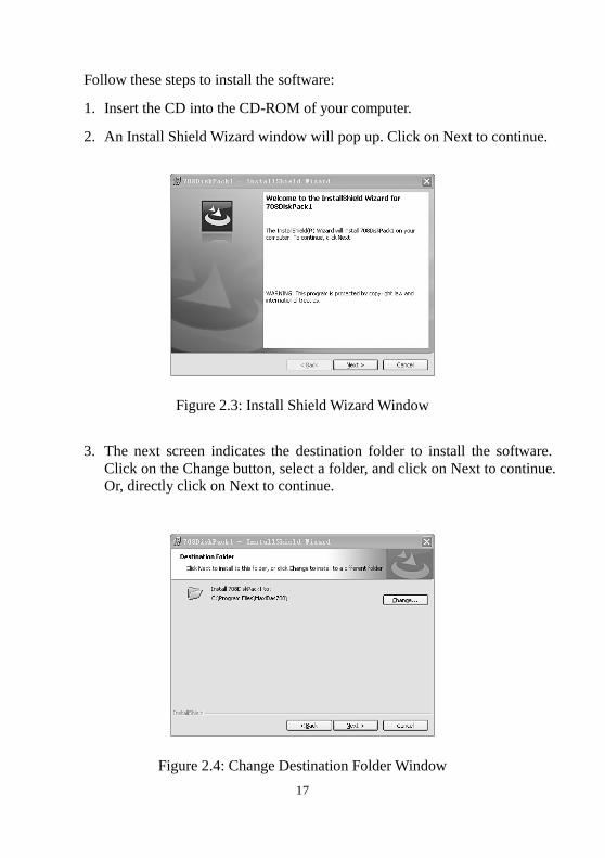
Follow these steps to install the software:
1. Insert the CD into the CD-ROM of your computer.
2. An Install Shield Wizard window will pop up. Click on Next to continue.
Figure 2.3: Install Shield Wizard Window
3. The next screen indicates the destination folder to install the software.
Click on the Change button, select a folder, and click on Next to continue.
Or, directly click on Next to continue.
Figure 2.4: Change Destination Folder Window
18
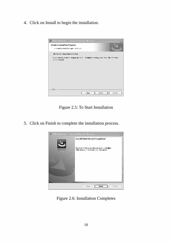
4. Click on Install to begin the installation.
Figure 2.5: To Start Installation
5. Click on Finish to complete the installation process.
Figure 2.6: Installation Completes
19
2.4. Register the Tool
User would enjoy our service Only after you had registered the tool on our
website:www.maxidas.com. Then you could download software, update
online, retrieve information and get warranty service. Before you finish
registration, a message will pop up every time the tool is powered on.
There are three ways to register the scan tool. Prior to registration, please
confirm your network is working properly.
A. Register on Internet
1. Log on the website www.maxidas.com.
2. Click on the Update tool bar at the top of the screen, and then select
User Register. Or,
Click on the Updates column in the lower right corner of the screen,
and select Register.
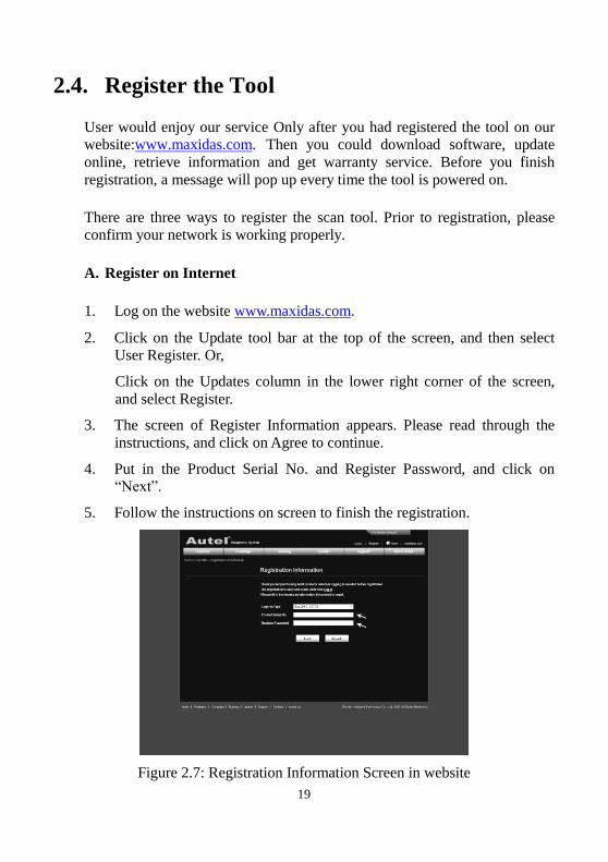
3. The screen of Register Information appears. Please read through the
instructions, and click on Agree to continue.
4. Put in the Product Serial No. and Register Password, and click on
“Next”.
5. Follow the instructions on screen to finish the registration.
Figure 2.7: Registration Information Screen in website
20
NOTE: Please use the System/Help > About function to find out the
Product Serial No. and Register Password. For details, please refer to
the Section 5.11 About. Or, you could find the information on the pop-up
registration MessageBox (Figure 2.8).
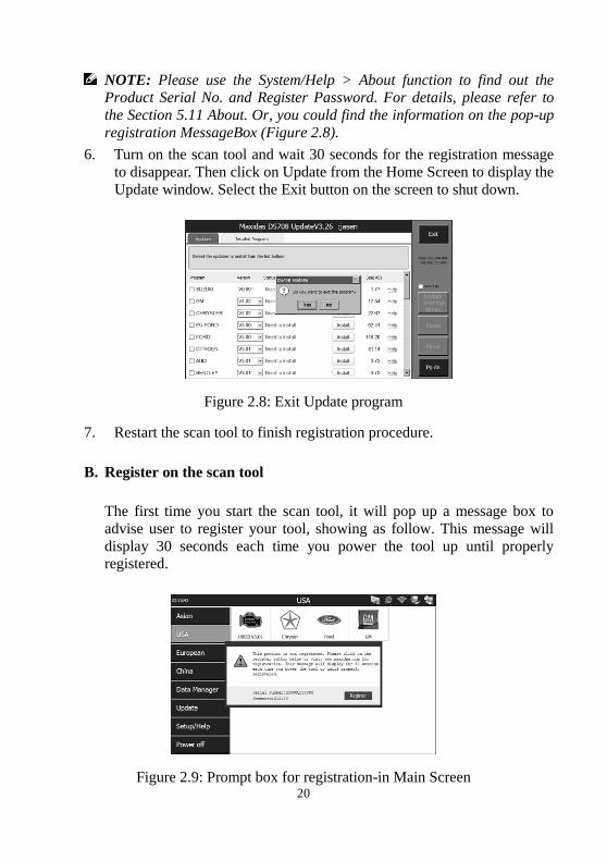
6. Turn on the scan tool and wait 30 seconds for the registration message
to disappear. Then click on Update from the Home Screen to display the
Update window. Select the Exit button on the screen to shut down.
Figure 2.8: Exit Update program
7. Restart the scan tool to finish registration procedure.
B. Register on the scan tool
The first time you start the scan tool, it will pop up a message box to
advise user to register your tool, showing as follow. This message will
display 30 seconds each time you power the tool up until properly
registered.
Figure 2.9: Prompt box for registration-in Main Screen
21
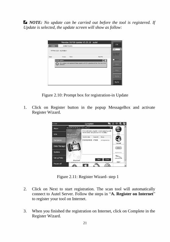
NOTE: No update can be carried out before the tool is registered. If
Update is selected, the update screen will show as follow:
Figure 2.10: Prompt box for registration-in Update
1. Click on Register button in the popup MessageBox and activate
Register Wizard.
Figure 2.11: Register Wizard- step 1
2. Click on Next to start registration. The scan tool will automatically
connect to Autel Server. Follow the steps in “A. Register on Internet”
to register your tool on Internet.
3. When you finished the registration on Internet, click on Complete in the
Register Wizard.
22
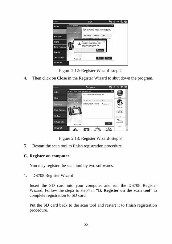
Figure 2.12: Register Wizard- step 2
4. Then click on Close in the Register Wizard to shut down the program.
Figure 2.13: Register Wizard- step 3
5. Restart the scan tool to finish registration procedure.
C. Register on computer
You may register the scan tool by two softwares.
1. DS708 Register Wizard
Insert the SD card into your computer and run the DS708 Register
Wizard. Follow the step2 to step4 in “B. Register on the scan tool” to
complete registration to SD card.
Put the SD card back to the scan tool and restart it to finish registration
procedure.

23
2. DS708 Update
Insert the SD card into your computer and run the DS708 Update. There
is a Register option in the log-in window (figure 6.3). When click on it, it
will automatically link to DS708 Register Wizard. Follow the step2 to
step4 in “B. Register on the scan tool” to complete registration to SD
card.
Put the SD card back to the scan tool and restart it to finish registration
procedure.
2.5. Test Startup and Vehicle Connection
Step 1: Connect the Cable.
Step 2: Enter the Vehicle information.
Step 3: Select the Diagnostic Function.
For details, please refer to Section 3.1 Test Startup and Vehicle Connection.
24
3. Diagnostics Applications
3.1. Test Startup and Vehicle Connection
3.1.1. Step 1: Connect the Cable
The method used to connect the scan tool to a vehicle’s DLC depends on the
vehicle’s configuration as follows:
A vehicle equipped with an On Board Diagnostics Two (OBD II) vehicle
management system supplies both communication and 12-volt power
through a standardized J-1962 data link connection (DLC).
A vehicle not equipped with an OBD II system supplies communication
through a DLC connection and sometimes supplies 12-volt power
through the cigarette lighter receptacle or a connection to the battery.
a. OBD II Vehicle Cable Connection
This type of connection generally requires the 15-pin main cable and an
OBD II adapter. To connect the 15-pin main cable, please follow these steps:
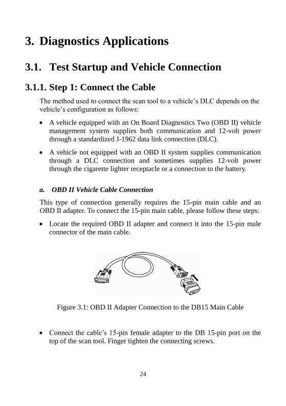
Locate the required OBD II adapter and connect it into the 15-pin male
connector of the main cable.
Figure 3.1: OBD II Adapter Connection to the DB15 Main Cable
Connect the cable’s 15-pin female adapter to the DB 15-pin port on the
top of the scan tool. Finger tighten the connecting screws.
25
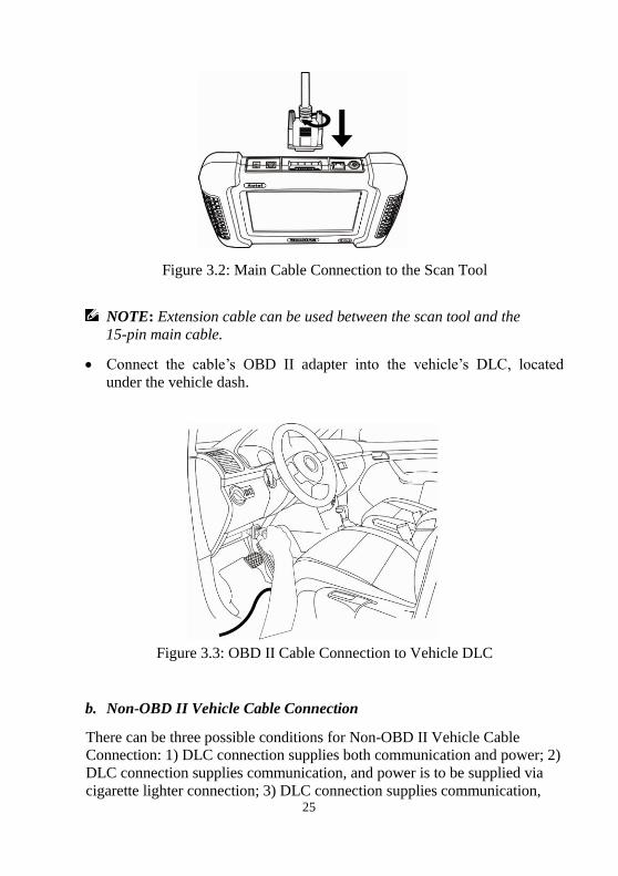
Figure 3.2: Main Cable Connection to the Scan Tool
NOTE: Extension cable can be used between the scan tool and the
15-pin main cable.
Connect the cable’s OBD II adapter into the vehicle’s DLC, located
under the vehicle dash.
Figure 3.3: OBD II Cable Connection to Vehicle DLC
b. Non-OBD II Vehicle Cable Connection
There can be three possible conditions for Non-OBD II Vehicle Cable
Connection: 1) DLC connection supplies both communication and power; 2)
DLC connection supplies communication, and power is to be supplied via
cigarette lighter connection; 3) DLC connection supplies communication,
26
and power is to be supplied through cable connection to vehicle battery.
This type of connection generally requires the vehicle-specific OBD I
adapter and the 15-pin main cable. To connect the DB15 main cable or
another similar cable, please follow these steps:
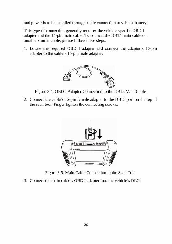
1. Locate the required OBD I adapter and connect the adapter’s 15-pin
adapter to the cable’s 15-pin male adapter.
Figure 3.4: OBD I Adapter Connection to the DB15 Main Cable
2. Connect the cable’s 15-pin female adapter to the DB15 port on the top of
the scan tool. Finger tighten the connecting screws.
Figure 3.5: Main Cable Connection to the Scan Tool
3. Connect the main cable’s OBD I adapter into the vehicle’s DLC.
27
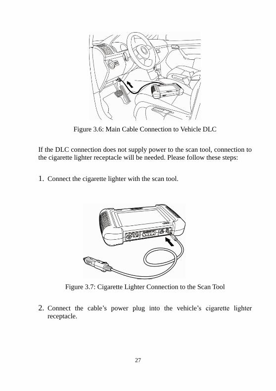
Figure 3.6: Main Cable Connection to Vehicle DLC
If the DLC connection does not supply power to the scan tool, connection to
the cigarette lighter receptacle will be needed. Please follow these steps:
1. Connect the cigarette lighter with the scan tool.
Figure 3.7: Cigarette Lighter Connection to the Scan Tool
2. Connect the cable’s power plug into the vehicle’s cigarette lighter
receptacle.

28
Figure 3.8: Plug into the Vehicle’s Cigarette Lighter Receptacle
NOTE: The vehicle’s DLC is not always located under the dash as shown
above.
NOTE: Some adapters may have more than one adapter or may have test leads instead of an adapter. Whatever the case, make the required
connections to the vehicle’s DLC.
If the cigarette lighter connection does not provide power either, connection
to the vehicle’s battery is necessary. Follow these steps:
1. Connect the cigarette lighter to the clipper cable.
Figure 3.9: Connection between Cigarette Lighter and Clipper Cable
2. Connect the clipper cable to the vehicle’s battery.
NOTE: The vehicle’s battery is usually located beside the engine.
NOTE: Please connect the red clipper to the anode and the black clipper
to the cathode.
29
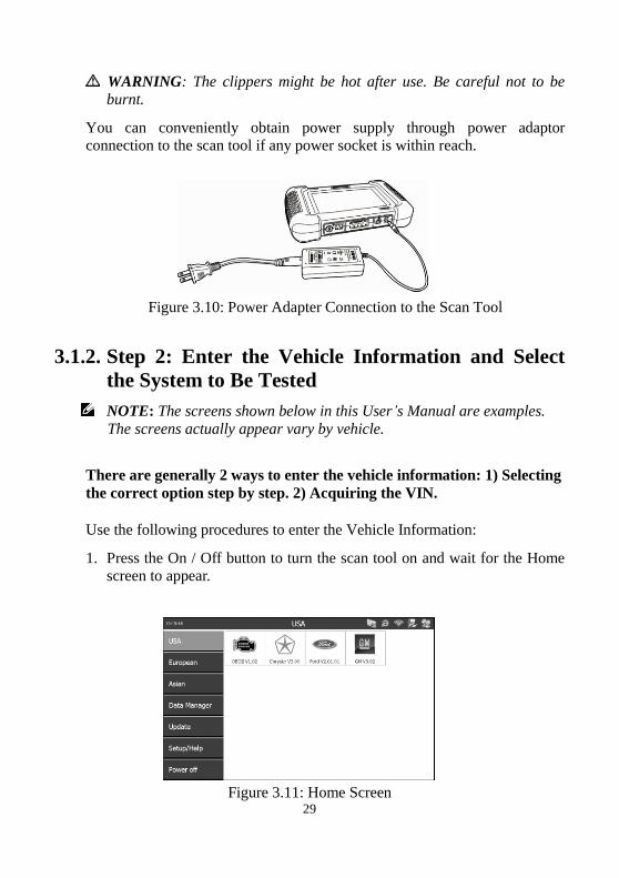
WARNING: The clippers might be hot after use. Be careful not to be
burnt.
You can conveniently obtain power supply through power adaptor
connection to the scan tool if any power socket is within reach.
Figure 3.10: Power Adapter Connection to the Scan Tool
3.1.2. Step 2: Enter the Vehicle Information and Select
the System to Be Tested
NOTE: The screens shown below in this User’s Manual are examples.
The screens actually appear vary by vehicle.
There are generally 2 ways to enter the vehicle information: 1) Selecting
the correct option step by step. 2) Acquiring the VIN.
Use the following procedures to enter the Vehicle Information:
1. Press the On / Off button to turn the scan tool on and wait for the Home
screen to appear.
Figure 3.11: Home Screen
30
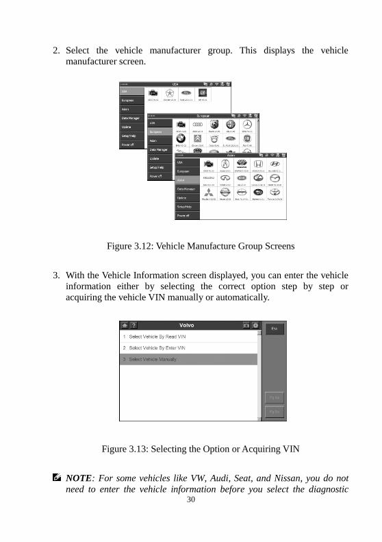
2. Select the vehicle manufacturer group. This displays the vehicle
manufacturer screen.
Figure 3.12: Vehicle Manufacture Group Screens
3. With the Vehicle Information screen displayed, you can enter the vehicle
information either by selecting the correct option step by step or
acquiring the vehicle VIN manually or automatically.
Figure 3.13: Selecting the Option or Acquiring VIN
NOTE: For some vehicles like VW, Audi, Seat, and Nissan, you do not
need to enter the vehicle information before you select the diagnostic
31
testing. For most others, you must enter the vehicle information before
you can do any testing. For vehicles like BENZ, both selecting the option
manually and acquiring the VIN are available for you to enter the vehicle
information.
Do one of the following:
To select the correct option step by step, go to step 4 and then step 6.
To acquire the vehicle VIN manually or automatically, go to step 5 and
then step 6.
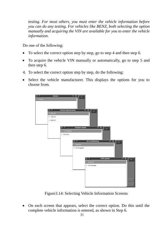
4. To select the correct option step by step, do the following:
Select the vehicle manufacturer. This displays the options for you to
choose from.
Figure3.14: Selecting Vehicle Information Screens
On each screen that appears, select the correct option. Do this until the
complete vehicle information is entered, as shown in Step 6.
32
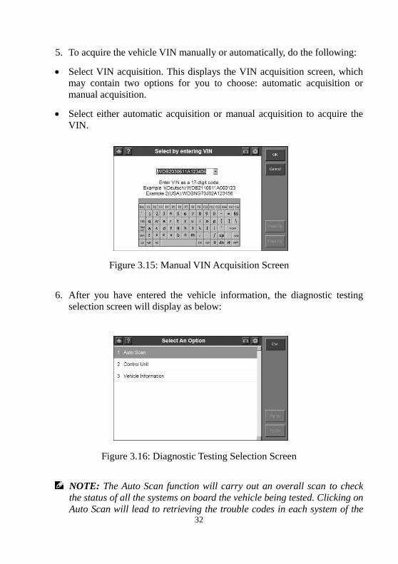
5. To acquire the vehicle VIN manually or automatically, do the following:
Select VIN acquisition. This displays the VIN acquisition screen, which
may contain two options for you to choose: automatic acquisition or
manual acquisition.
Select either automatic acquisition or manual acquisition to acquire the
VIN.
Figure 3.15: Manual VIN Acquisition Screen
6. After you have entered the vehicle information, the diagnostic testing
selection screen will display as below:
Figure 3.16: Diagnostic Testing Selection Screen
NOTE: The Auto Scan function will carry out an overall scan to check
the status of all the systems on board the vehicle being tested. Clicking on
Auto Scan will lead to retrieving the trouble codes in each system of the
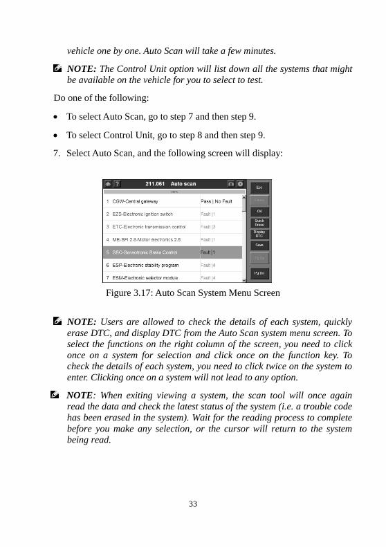
33
vehicle one by one. Auto Scan will take a few minutes.
NOTE: The Control Unit option will list down all the systems that might be available on the vehicle for you to select to test.
Do one of the following:
To select Auto Scan, go to step 7 and then step 9.
To select Control Unit, go to step 8 and then step 9.
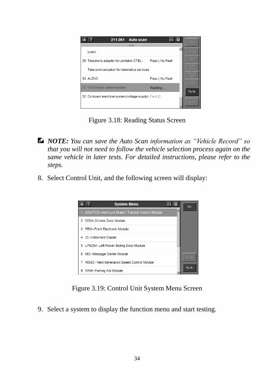
7. Select Auto Scan, and the following screen will display:
Figure 3.17: Auto Scan System Menu Screen
NOTE: Users are allowed to check the details of each system, quickly
erase DTC, and display DTC from the Auto Scan system menu screen. To select the functions on the right column of the screen, you need to click
once on a system for selection and click once on the function key. To check the details of each system, you need to click twice on the system to
enter. Clicking once on a system will not lead to any option.
NOTE: When exiting viewing a system, the scan tool will once again
read the data and check the latest status of the system (i.e. a trouble code
has been erased in the system). Wait for the reading process to complete
before you make any selection, or the cursor will return to the system being read.
34
Figure 3.18: Reading Status Screen
NOTE: You can save the Auto Scan information as “Vehicle Record” so
that you will not need to follow the vehicle selection process again on the
same vehicle in later tests. For detailed instructions, please refer to the steps.
8. Select Control Unit, and the following screen will display:
Figure 3.19: Control Unit System Menu Screen
9. Select a system to display the function menu and start testing.
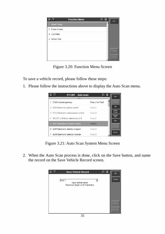
35
Figure 3.20: Function Menu Screen
To save a vehicle record, please follow these steps:
1. Please follow the instructions above to display the Auto Scan menu.
Figure 3.21: Auto Scan System Menu Screen
2. When the Auto Scan process is done, click on the Save button, and name
the record on the Save Vehicle Record screen.
36
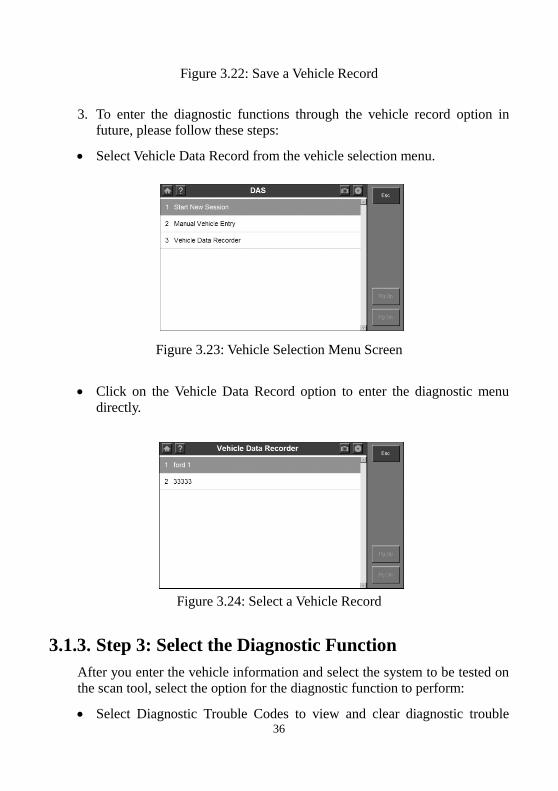
Figure 3.22: Save a Vehicle Record
3. To enter the diagnostic functions through the vehicle record option in
future, please follow these steps:
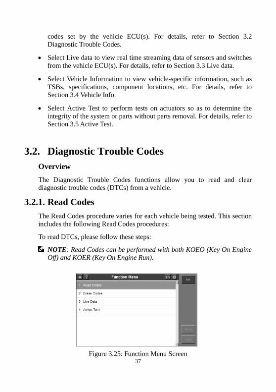
Select Vehicle Data Record from the vehicle selection menu.
Figure 3.23: Vehicle Selection Menu Screen
Click on the Vehicle Data Record option to enter the diagnostic menu
directly.
Figure 3.24: Select a Vehicle Record
3.1.3. Step 3: Select the Diagnostic Function
After you enter the vehicle information and select the system to be tested on
the scan tool, select the option for the diagnostic function to perform:
Select Diagnostic Trouble Codes to view and clear diagnostic trouble
37
codes set by the vehicle ECU(s). For details, refer to Section 3.2
Diagnostic Trouble Codes.
Select Live data to view real time streaming data of sensors and switches
from the vehicle ECU(s). For details, refer to Section 3.3 Live data.
Select Vehicle Information to view vehicle-specific information, such as
TSBs, specifications, component locations, etc. For details, refer to
Section 3.4 Vehicle Info.
Select Active Test to perform tests on actuators so as to determine the
integrity of the system or parts without parts removal. For details, refer to
Section 3.5 Active Test.
3.2. Diagnostic Trouble Codes
Overview
The Diagnostic Trouble Codes functions allow you to read and clear
diagnostic trouble codes (DTCs) from a vehicle.
3.2.1. Read Codes
The Read Codes procedure varies for each vehicle being tested. This section
includes the following Read Codes procedures:
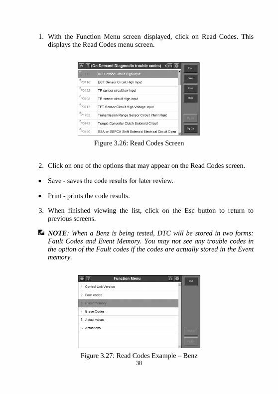
To read DTCs, please follow these steps:
NOTE: Read Codes can be performed with both KOEO (Key On Engine Off) and KOER (Key On Engine Run).
Figure 3.25: Function Menu Screen
38
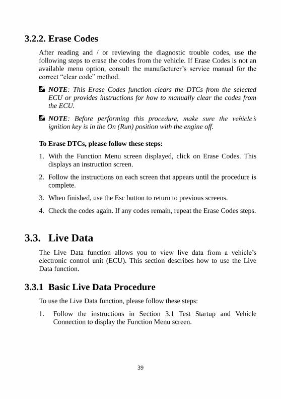
1. With the Function Menu screen displayed, click on Read Codes. This
displays the Read Codes menu screen.
Figure 3.26: Read Codes Screen
2. Click on one of the options that may appear on the Read Codes screen.
Save - saves the code results for later review.
Print - prints the code results.
3. When finished viewing the list, click on the Esc button to return to
previous screens.
NOTE: When a Benz is being tested, DTC will be stored in two forms: Fault Codes and Event Memory. You may not see any trouble codes in
the option of the Fault codes if the codes are actually stored in the Event memory.
Figure 3.27: Read Codes Example – Benz
39
3.2.2. Erase Codes
After reading and / or reviewing the diagnostic trouble codes, use the
following steps to erase the codes from the vehicle. If Erase Codes is not an
available menu option, consult the manufacturer’s service manual for the
correct “clear code” method.
NOTE: This Erase Codes function clears the DTCs from the selected
ECU or provides instructions for how to manually clear the codes from the ECU.
NOTE: Before performing this procedure, make sure the vehicle’s
ignition key is in the On (Run) position with the engine off.
To Erase DTCs, please follow these steps:
1. With the Function Menu screen displayed, click on Erase Codes. This
displays an instruction screen.
2. Follow the instructions on each screen that appears until the procedure is
complete.
3. When finished, use the Esc button to return to previous screens.
4. Check the codes again. If any codes remain, repeat the Erase Codes steps.
3.3. Live Data
The Live Data function allows you to view live data from a vehicle’s
electronic control unit (ECU). This section describes how to use the Live
Data function.
3.3.1 Basic Live Data Procedure
To use the Live Data function, please follow these steps:
1. Follow the instructions in Section 3.1 Test Startup and Vehicle
Connection to display the Function Menu screen.
40
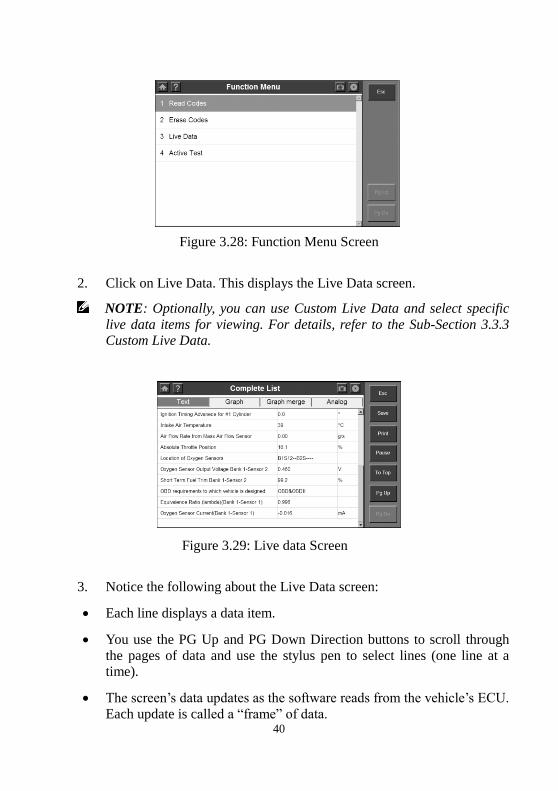
Figure 3.28: Function Menu Screen
2. Click on Live Data. This displays the Live Data screen.
NOTE: Optionally, you can use Custom Live Data and select specific
live data items for viewing. For details, refer to the Sub-Section 3.3.3 Custom Live Data.
Figure 3.29: Live data Screen
3. Notice the following about the Live Data screen:
Each line displays a data item.
You use the PG Up and PG Down Direction buttons to scroll through
the pages of data and use the stylus pen to select lines (one line at a
time).
The screen’s data updates as the software reads from the vehicle’s ECU.
Each update is called a “frame” of data.
41
You can stop and start the live readings at any time by clicking on the
Pause button. When you stop the readings, the data “freezes” on the
screen.
The function keys and options at the top and on the right of the screen
allow you to perform several other functions on the screen. For details,
refer to Sub-Section 3.3.2 Live Data Functions.
4. When you are finished using the screen, click on ESC to return to the
Function Menu screen.
3.3.2 Live Data Functions
Functions Overview
There are several functions you can use on the Live Data screen. Most of the
functions are activated with the function buttons at the top and on the right
of the screen.
These functions, described in detail on the next few pages, include the
following:
Text/Graph / Graph Merge/Analog– depending on the type of data on a
line, changes the view of a selected line from digital to graphical or
analog.
Record Data – records the data for viewing again at a later time.
To Top – moves a selected data item to the top of the screen.
Print – prints the data currently displayed.
1. Text/ Graph / Graph Merge / Analog
The Text/ Graph / Graph Merge / Analog function allows you to change the
display type of the data on the Live Data screen. Depending on the type of
data on the screen, you can change the data from digital to a graphical or
analog gauge display.
42
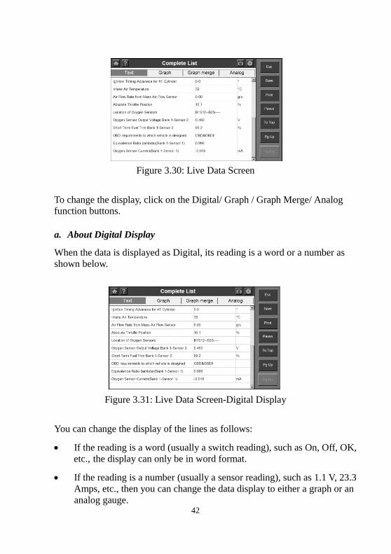
Figure 3.30: Live Data Screen
To change the display, click on the Digital/ Graph / Graph Merge/ Analog
function buttons.
a. About Digital Display
When the data is displayed as Digital, its reading is a word or a number as
shown below.
Figure 3.31: Live Data Screen-Digital Display
You can change the display of the lines as follows:
If the reading is a word (usually a switch reading), such as On, Off, OK,
etc., the display can only be in word format.
If the reading is a number (usually a sensor reading), such as 1.1 V, 23.3
Amps, etc., then you can change the data display to either a graph or an
analog gauge.
43
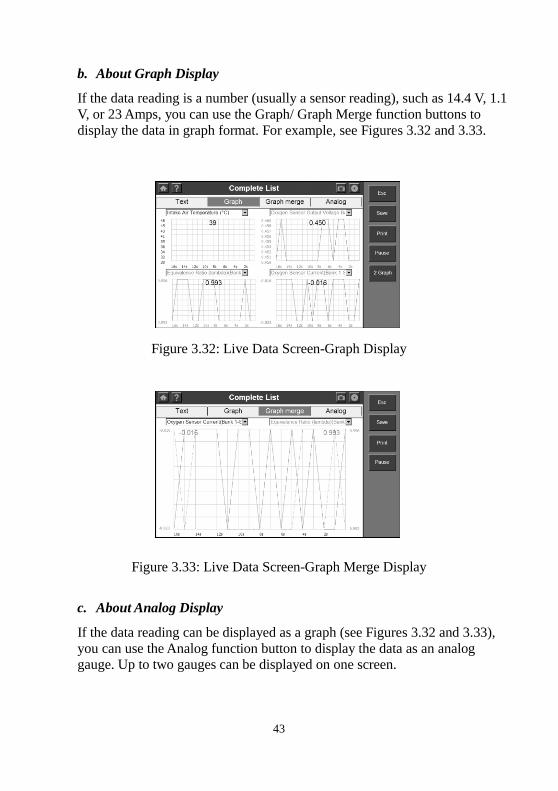
b. About Graph Display
If the data reading is a number (usually a sensor reading), such as 14.4 V, 1.1
V, or 23 Amps, you can use the Graph/ Graph Merge function buttons to
display the data in graph format. For example, see Figures 3.32 and 3.33.
Figure 3.32: Live Data Screen-Graph Display
Figure 3.33: Live Data Screen-Graph Merge Display
c. About Analog Display
If the data reading can be displayed as a graph (see Figures 3.32 and 3.33),
you can use the Analog function button to display the data as an analog gauge. Up to two gauges can be displayed on one screen.

44
Figure 3.34: Live Data Screen - Analog Display
2. Record Data
The Record function allows you to save data files to the SD card and then
use the Playback function to view the saved files.
NOTE: The length of time for each frame varies per vehicle. Generally, one frame of data is about 1/4 of a second, or 4 frames per second.
To record to SD Card, please follow these steps:
1. Follow the steps in the Sub-Section 3.3.1 Basic Live Data Procedure to
display the Live Data screen.
Figure 3.35: Live Data Screen - Record Function
NOTE: The recording will include all data lines in the list but not only the data viewable on the screen.
2. Click on the Save function button. This does the following:
45
Temporarily shades the Save function button.
Automatically records the frames of data that occur after clicking on the
button.
NOTE: You can record any number of files as long as they fit on the free space on the SD card. To stop recording, just click on the Stop function
button.
3. When the recording stops, continue viewing live data or use the ESC
button to return to previous screens.
4. To view the saved data file, refer to Section 4.2 Playback.
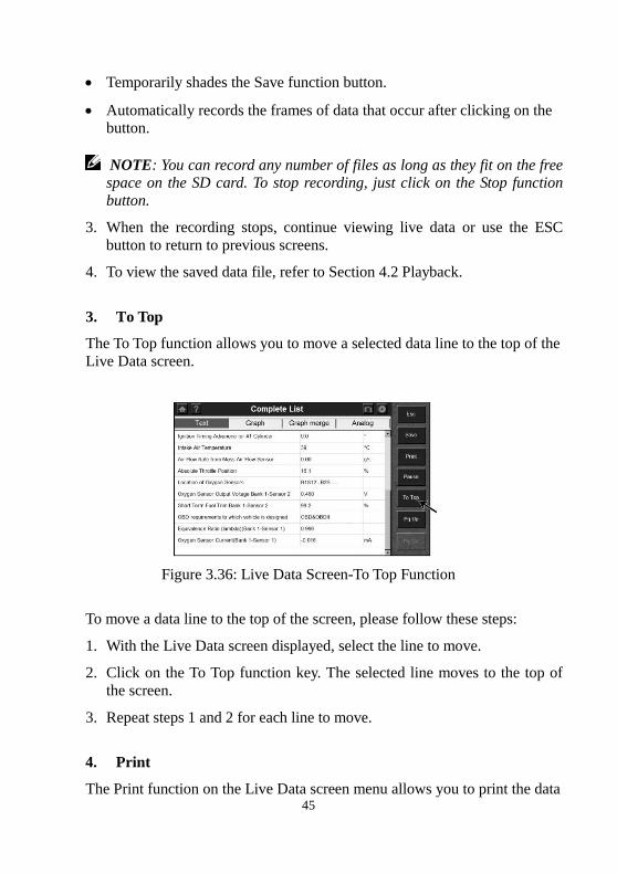
3. To Top
The To Top function allows you to move a selected data line to the top of the
Live Data screen.
Figure 3.36: Live Data Screen-To Top Function
To move a data line to the top of the screen, please follow these steps:
1. With the Live Data screen displayed, select the line to move.
2. Click on the To Top function key. The selected line moves to the top of
the screen.
3. Repeat steps 1 and 2 for each line to move.
4. Print
The Print function on the Live Data screen menu allows you to print the data
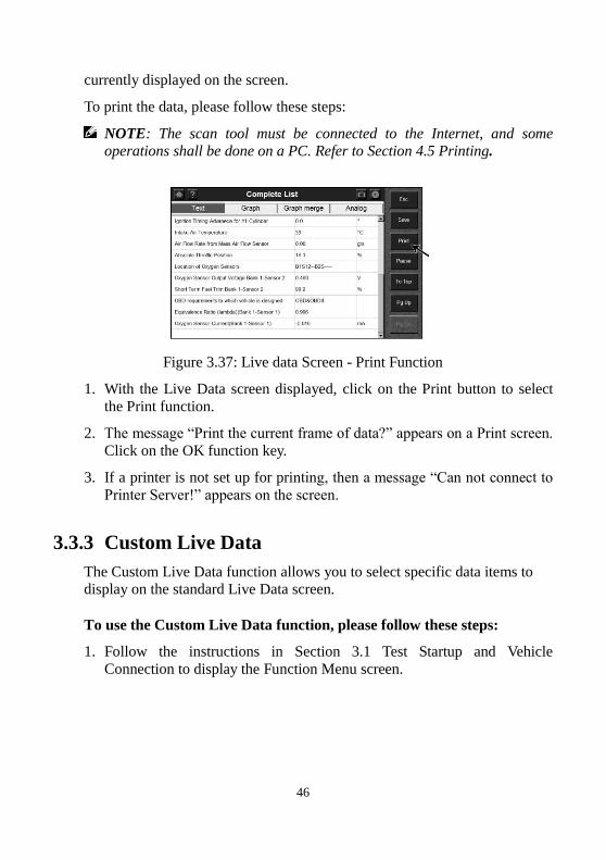
46
currently displayed on the screen.
To print the data, please follow these steps:
NOTE: The scan tool must be connected to the Internet, and some operations shall be done on a PC. Refer to Section 4.5 Printing.
Figure 3.37: Live data Screen - Print Function
1. With the Live Data screen displayed, click on the Print button to select
the Print function.
2. The message “Print the current frame of data?” appears on a Print screen.
Click on the OK function key.
3. If a printer is not set up for printing, then a message “Can not connect to
Printer Server!” appears on the screen.
3.3.3 Custom Live Data
The Custom Live Data function allows you to select specific data items to
display on the standard Live Data screen.
To use the Custom Live Data function, please follow these steps:
1. Follow the instructions in Section 3.1 Test Startup and Vehicle
Connection to display the Function Menu screen.
47
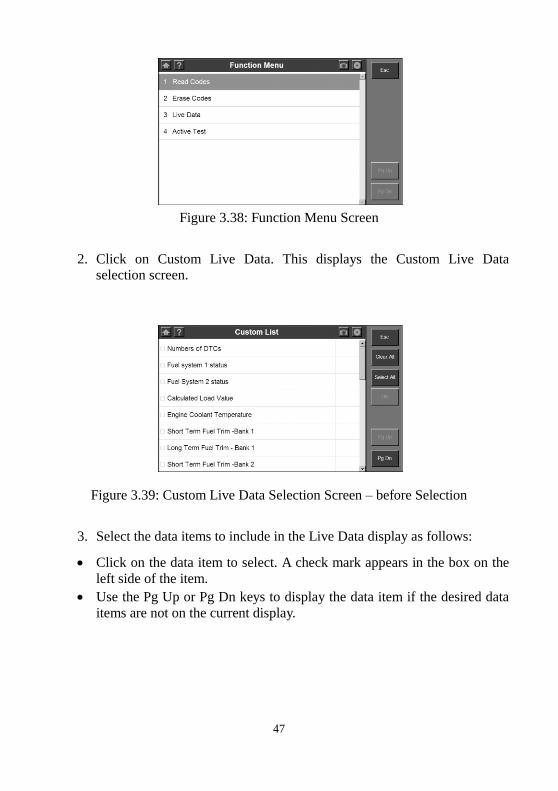
Figure 3.38: Function Menu Screen
2. Click on Custom Live Data. This displays the Custom Live Data
selection screen.
Figure 3.39: Custom Live Data Selection Screen – before Selection
3. Select the data items to include in the Live Data display as follows:
Click on the data item to select. A check mark appears in the box on the
left side of the item.
Use the Pg Up or Pg Dn keys to display the data item if the desired data
items are not on the current display.
48
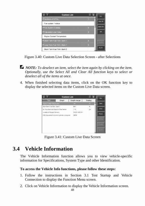
Figure 3.40: Custom Live Data Selection Screen - after Selections
NOTE: To deselect an item, select the item again by clicking on the item. Optionally, use the Select All and Clear All function keys to select or
deselect all of the items at once.
4. When finished selecting data items, click on the OK function key to
display the selected items on the Custom Live Data screen.
Figure 3.41: Custom Live Data Screen
3.4 Vehicle Information
The Vehicle Information function allows you to view vehicle-specific
information for Specifications, System Type and other Identification.
To access the Vehicle Info functions, please follow these steps:
1. Follow the instructions in Section 3.1 Test Startup and Vehicle
Connection to display the Function Menu screen.
2. Click on Vehicle Information to display the Vehicle Information screen.
49
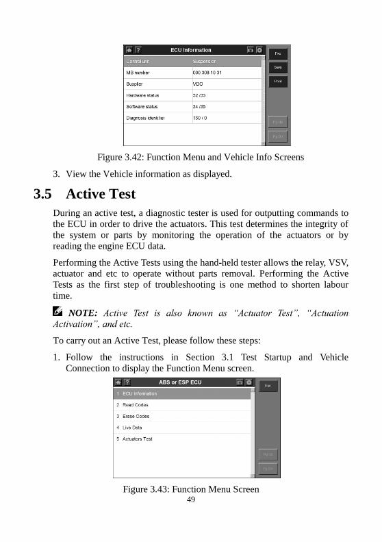
Figure 3.42: Function Menu and Vehicle Info Screens
3. View the Vehicle information as displayed.
3.5 Active Test
During an active test, a diagnostic tester is used for outputting commands to
the ECU in order to drive the actuators. This test determines the integrity of
the system or parts by monitoring the operation of the actuators or by
reading the engine ECU data.
Performing the Active Tests using the hand-held tester allows the relay, VSV,
actuator and etc to operate without parts removal. Performing the Active
Tests as the first step of troubleshooting is one method to shorten labour
time.
NOTE: Active Test is also known as “Actuator Test”, “Actuation Activation”, and etc.
To carry out an Active Test, please follow these steps:
1. Follow the instructions in Section 3.1 Test Startup and Vehicle
Connection to display the Function Menu screen.
Figure 3.43: Function Menu Screen
50
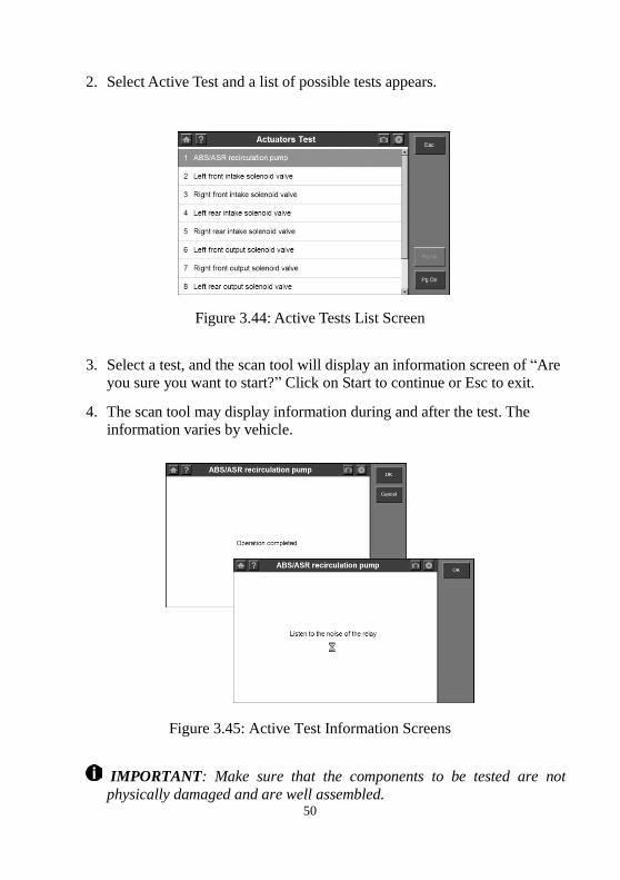
2. Select Active Test and a list of possible tests appears.
Figure 3.44: Active Tests List Screen
3. Select a test, and the scan tool will display an information screen of “Are
you sure you want to start?” Click on Start to continue or Esc to exit.
4. The scan tool may display information during and after the test. The
information varies by vehicle.
Figure 3.45: Active Test Information Screens
IMPORTANT: Make sure that the components to be tested are not
physically damaged and are well assembled.
51
WARNING: Please stop repairing the components to be tested before the
test starts and keep a certain distance during the test.
3.6 Generic OBD II Functions
The OBD II Diagnostics function is a fast-access option that allows you to
carry out a quick test on the engine system of OBD II vehicles.
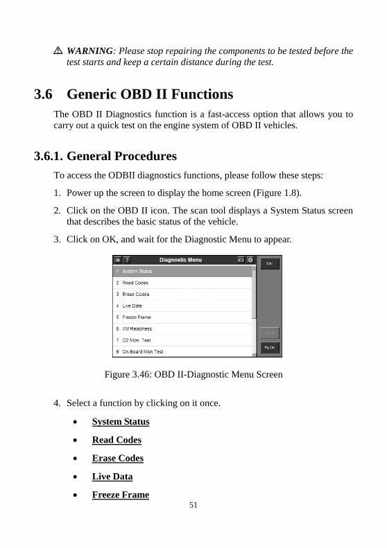
3.6.1. General Procedures
To access the ODBII diagnostics functions, please follow these steps:
1. Power up the screen to display the home screen (Figure 1.8).
2. Click on the OBD II icon. The scan tool displays a System Status screen
that describes the basic status of the vehicle.
3. Click on OK, and wait for the Diagnostic Menu to appear.
Figure 3.46: OBD II-Diagnostic Menu Screen
4. Select a function by clicking on it once.
System Status
Read Codes
Erase Codes
Live Data
Freeze Frame
52
I/M Readiness
O2 Mon. Test
On-Board Mon. Test
Component Test
Vehicle Info.
Modules Present
DTC Lookup
NOTE: Some functions are supported only on certain vehicle makes.
3.6.2. Functions Description
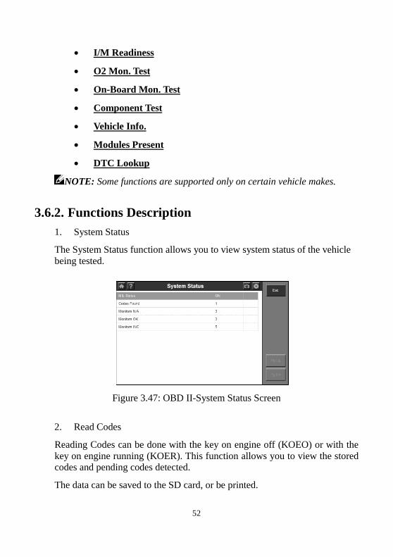
1. System Status
The System Status function allows you to view system status of the vehicle
being tested.
Figure 3.47: OBD II-System Status Screen
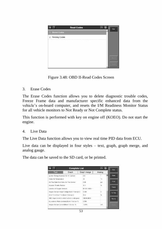
2. Read Codes
Reading Codes can be done with the key on engine off (KOEO) or with the
key on engine running (KOER). This function allows you to view the stored codes and pending codes detected.
The data can be saved to the SD card, or be printed.
53
Figure 3.48: OBD II-Read Codes Screen
3. Erase Codes
The Erase Codes function allows you to delete diagnostic trouble codes,
Freeze Frame data and manufacturer specific enhanced data from the
vehicle’s on-board computer, and resets the I/M Readiness Monitor Status
for all vehicle monitors to Not Ready or Not Complete status.
This function is performed with key on engine off (KOEO). Do not start the
engine.
4. Live Data
The Live Data function allows you to view real time PID data from ECU.
Live data can be displayed in four styles – text, graph, graph merge, and
analog gauge.
The data can be saved to the SD card, or be printed.
54
Figure 3.49: OBD II-Live Data Screen
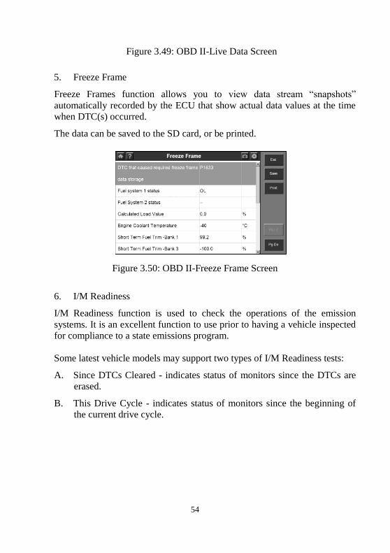
5. Freeze Frame
Freeze Frames function allows you to view data stream “snapshots”
automatically recorded by the ECU that show actual data values at the time
when DTC(s) occurred.
The data can be saved to the SD card, or be printed.
Figure 3.50: OBD II-Freeze Frame Screen
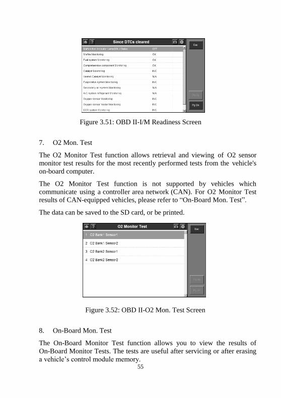
6. I/M Readiness
I/M Readiness function is used to check the operations of the emission
systems. It is an excellent function to use prior to having a vehicle inspected
for compliance to a state emissions program.
Some latest vehicle models may support two types of I/M Readiness tests:
A. Since DTCs Cleared - indicates status of monitors since the DTCs are
erased.
B. This Drive Cycle - indicates status of monitors since the beginning of
the current drive cycle.
55
Figure 3.51: OBD II-I/M Readiness Screen
7. O2 Mon. Test
The O2 Monitor Test function allows retrieval and viewing of O2 sensor
monitor test results for the most recently performed tests from the vehicle's
on-board computer.
The O2 Monitor Test function is not supported by vehicles which
communicate using a controller area network (CAN). For O2 Monitor Test
results of CAN-equipped vehicles, please refer to “On-Board Mon. Test”.
The data can be saved to the SD card, or be printed.
Figure 3.52: OBD II-O2 Mon. Test Screen
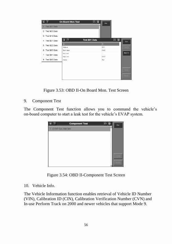
8. On-Board Mon. Test
The On-Board Monitor Test function allows you to view the results of
On-Board Monitor Tests. The tests are useful after servicing or after erasing
a vehicle’s control module memory.
56
Figure 3.53: OBD II-On Board Mon. Test Screen
9. Component Test
The Component Test function allows you to command the vehicle’s
on-board computer to start a leak test for the vehicle’s EVAP system.
Figure 3.54: OBD II-Component Test Screen
10. Vehicle Info.
The Vehicle Information function enables retrieval of Vehicle ID Number
(VIN), Calibration ID (CIN), Calibration Verification Number (CVN) and
In-use Perform Track on 2000 and newer vehicles that support Mode 9.
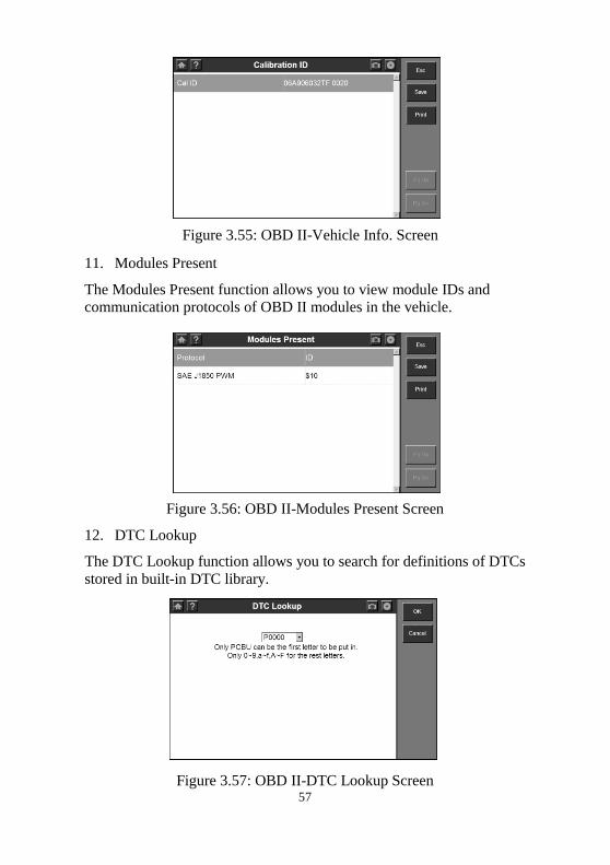
57
Figure 3.55: OBD II-Vehicle Info. Screen
11. Modules Present
The Modules Present function allows you to view module IDs and
communication protocols of OBD II modules in the vehicle.
Figure 3.56: OBD II-Modules Present Screen
12. DTC Lookup
The DTC Lookup function allows you to search for definitions of DTCs
stored in built-in DTC library.
Figure 3.57: OBD II-DTC Lookup Screen
58
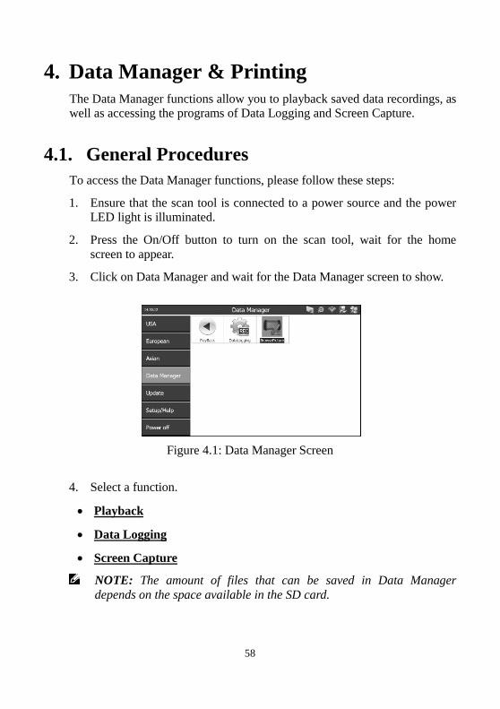
4. Data Manager & Printing
The Data Manager functions allow you to playback saved data recordings, as
well as accessing the programs of Data Logging and Screen Capture.
4.1. General Procedures
To access the Data Manager functions, please follow these steps:
1. Ensure that the scan tool is connected to a power source and the power
LED light is illuminated.
2. Press the On/Off button to turn on the scan tool, wait for the home
screen to appear.
3. Click on Data Manager and wait for the Data Manager screen to show.
Figure 4.1: Data Manager Screen
4. Select a function.
Playback
Data Logging
Screen Capture
NOTE: The amount of files that can be saved in Data Manager
depends on the space available in the SD card.
59
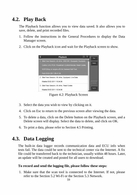
4.2. Play Back
The Playback function allows you to view data saved. It also allows you to
save, delete, and print recorded files.
1. Follow the instructions in the General Procedures to display the Data
Manager screen.
2. Click on the Playback icon and wait for the Playback screen to show.
Figure 4.2: Playback Screen
3. Select the data you wish to view by clicking on it.
4. Click on Esc to return to the previous screen after viewing the data.
5. To delete a data, click on the Delete button on the Playback screen, and a
Delete screen will display. Select the data to delete, and click on OK.
6. To print a data, please refer to Section 4.5 Printing.
4.3. Data Logging
The built-in data logger records communication data and ECU info when
tests fail. The data could be sent to the technical center via the Internet. A fix
file could be transferred back to the technician, usually within 48 hours. Later,
an update will be created and posted for all users to download.
To record and send the logging file, please follow these steps:
1. Make sure that the scan tool is connected to the Internet. If not, please
refer to the Section 5.2 Wi-Fi or the Section 5.3 Network.
60
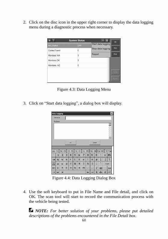
2. Click on the disc icon in the upper right corner to display the data logging
menu during a diagnostic process when necessary.
Figure 4.3: Data Logging Menu
3. Click on “Start data logging”, a dialog box will display.
Figure 4.4: Data Logging Dialog Box
4. Use the soft keyboard to put in File Name and File detail, and click on
OK. The scan tool will start to record the communication process with the vehicle being tested.
NOTE: For better solution of your problems, please put detailed descriptions of the problems encountered in the File Detail box.
61
5. Click on the disc icon in the upper right corner to display the data logging
menu, and click on “Stop data logging” to stop recording.
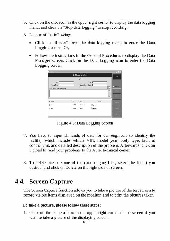
6. Do one of the following:
Click on “Report” from the data logging menu to enter the Data
Logging screen. Or,
Follow the instructions in the General Procedures to display the Data
Manager screen. Click on the Data Logging icon to enter the Data
Logging screen.
Figure 4.5: Data Logging Screen
7. You have to input all kinds of data for our engineers to identify the
fault(s), which include vehicle VIN, model year, body type, fault at
control unit, and detailed description of the problem. Afterwards, click on
Upload to send your problems to the Autel technical center.
8. To delete one or some of the data logging files, select the file(s) you
desired, and click on Delete on the right side of screen.
4.4. Screen Capture
The Screen Capture function allows you to take a picture of the test screen to
record visible items displayed on the monitor, and to print the pictures taken.
To take a picture, please follow these steps:
1. Click on the camera icon in the upper right corner of the screen if you
want to take a picture of the displaying screen.
62
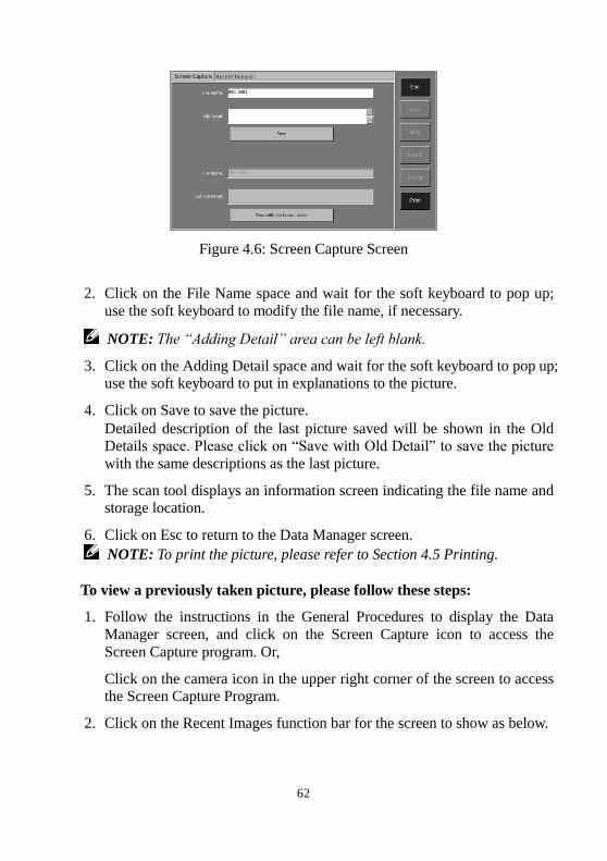
Figure 4.6: Screen Capture Screen
2. Click on the File Name space and wait for the soft keyboard to pop up;
use the soft keyboard to modify the file name, if necessary.
NOTE: The “Adding Detail” area can be left blank.
3. Click on the Adding Detail space and wait for the soft keyboard to pop up;
use the soft keyboard to put in explanations to the picture.
4. Click on Save to save the picture.
Detailed description of the last picture saved will be shown in the Old
Details space. Please click on “Save with Old Detail” to save the picture
with the same descriptions as the last picture.
5. The scan tool displays an information screen indicating the file name and
storage location.
6. Click on Esc to return to the Data Manager screen.
NOTE: To print the picture, please refer to Section 4.5 Printing.
To view a previously taken picture, please follow these steps:
1. Follow the instructions in the General Procedures to display the Data
Manager screen, and click on the Screen Capture icon to access the
Screen Capture program. Or,
Click on the camera icon in the upper right corner of the screen to access
the Screen Capture Program.
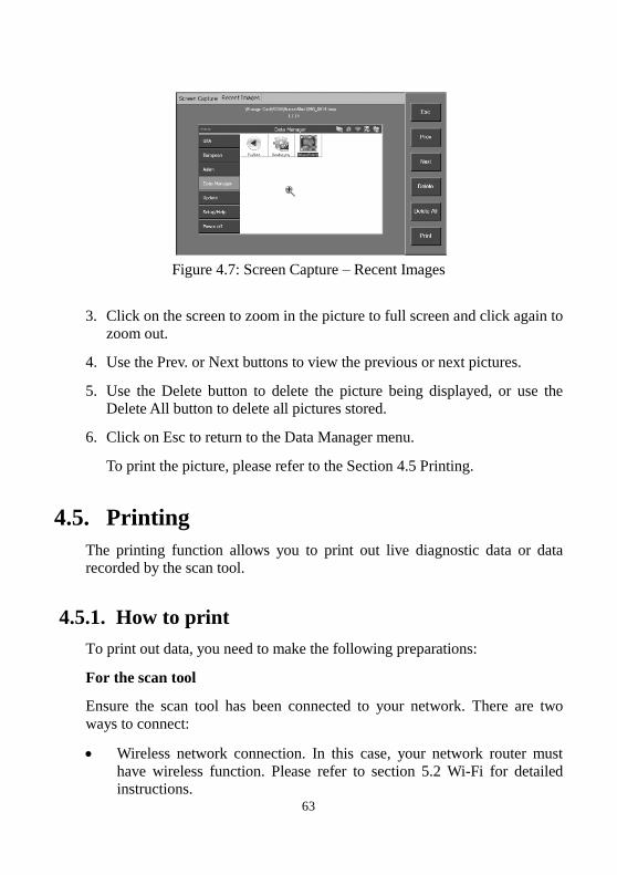
2. Click on the Recent Images function bar for the screen to show as below.
63
Figure 4.7: Screen Capture – Recent Images
3. Click on the screen to zoom in the picture to full screen and click again to
zoom out.
4. Use the Prev. or Next buttons to view the previous or next pictures.
5. Use the Delete button to delete the picture being displayed, or use the
Delete All button to delete all pictures stored.
6. Click on Esc to return to the Data Manager menu.
To print the picture, please refer to the Section 4.5 Printing.
4.5. Printing
The printing function allows you to print out live diagnostic data or data
recorded by the scan tool.
4.5.1. How to print
To print out data, you need to make the following preparations:
For the scan tool
Ensure the scan tool has been connected to your network. There are two
ways to connect:
Wireless network connection. In this case, your network router must
have wireless function. Please refer to section 5.2 Wi-Fi for detailed
instructions.
64
Cable network connection. Connect the scan tool to network router with
a RS232 Serial Cable supplied. Please refer to section 5.3 Network for
detailed instructions.
For the computer
Ensure that the Print Server software has been properly installed to your
computer. Please refer to Section 2.3 Install the PC Software for
detailed instructions.
Ensure that the computer has been properly connected to a printer.
Run the Print Server software on computer.
To print the data, follow these steps:
1. When the live data is printable, a Print function key appears in the right
column of the screen.
NOTE: Now only the data in text is printable. If you want to print some
information which is unprintable, you can use the Screen Capture
function to take a picture of the test screen, then print the picture taken.
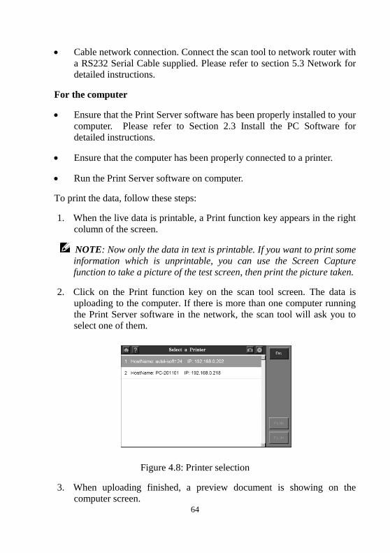
2. Click on the Print function key on the scan tool screen. The data is
uploading to the computer. If there is more than one computer running
the Print Server software in the network, the scan tool will ask you to
select one of them.
Figure 4.8: Printer selection
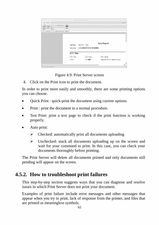
3. When uploading finished, a preview document is showing on the
computer screen.
65
Figure 4.9: Print Server screen
4. Click on the Print icon to print the document.
In order to print more easily and smoothly, there are some printing options
you can choose.
Quick Print : quick-print the document using current options.
Print : print the document in a normal procedure.
Test Print: print a text page to check if the print function is working
properly.
Auto print:
Checked: automatically print all documents uploading
Unchecked: stack all documents uploading up on the screen and
wait for your command to print. In this case, you can check your
documents thoroughly before printing.
The Print Server will delete all documents printed and only documents still
pending will appear on the screen.
4.5.2. How to troubleshoot print failures
This step-by-step section suggests ways that you can diagnose and resolve
issues in which Print Server does not print your document.
Examples of print failure include error messages and other messages that
appear when you try to print, lack of response from the printer, and files that
are printed as meaningless symbols.

66
To resolve print failure, you must determine its cause. Causes typically fit
one of four major categories:
Damaged documents or damaged content in documents
The Print Server program
The printer driver
Connectivity/hardware
It is important not to assume too quickly what the cause of your printing
problem may be. Instead, rely on systematic troubleshooting to reveal the
real cause.
Perform the following easy tests to help determine the type of cause that you
are experiencing.
Step 1: Test Printing in Other Documents
Damaged documents or documents that contain damaged graphics or
damaged fonts can cause print errors. Before you reinstall drivers or
software, test the ability of the Print Server program to print. To do this,
perform this test:
Open a new blank document in Print Server.
Click on the Test Print button to print the test document.
The success or failure of the preceding test shows whether the Print Server
can print in general.
If you receive no errors in the test document, but you still cannot print your
original document, it is likely that your original document is damaged.
This may be true even if you can print the same document on another
computer. This is because there are many situations in which the symptoms
of file damage appear on some computers and not on others.
Again, it is important to rely on systematic troubleshooting, rather than
assuming what the cause of the problem is. Therefore, if you cannot print a
particular document, but you can print other documents in the Print Server,
you probably have a damaged document and should troubleshoot the problem accordingly.
If the Print Server cannot print at all, go to Step 2.
67
Step 2: Test Printing in Other Programs
Understanding the scope of the printing problem may reveal its cause. For
example, some printing problems only affect the Print Server, and other
printing problems affect several or all of your Microsoft Windows programs.
The following tests can help determine whether this issue involves multiple
programs or whether the symptoms are unique to the Print Server.
Test the print function in your Office programs or Web browser. You also
can try to print a test page for your printer. To do all these, please refer to
Microsoft Windows and Office applications Manuals.
If you cannot print a test page, or if you cannot print in several or all of your
Windows programs, you may have a printer driver problem, a Windows
problem, or a hardware/connectivity problem. In this case, go to Step 4.
If you can print without problems in all your programs except the Print
Server, go to Step 3.
Step 3: Test Printing with Different Printer Drivers
If the Print Server is the only program on your computer that cannot print,
you may think that it is the cause of the problem. It is important to remember
that the Print Server is a very printer-intensive program. This means that a
minor problem with the printer driver could affect the Print Server.
To determine whether the printer driver is the cause of the problem, you can
test different drivers and try to print to another printer. If no other printer is
available, contact the manufacturer to find out whether there is an updated
version of the driver.
If the printing problem occurs with a different printer driver, go to Step 4.
Step 4: Print Overhaul
At this point, you have verified that the printing problem is not limited to a
particular document or a particular printer driver, and that the problem is
limited to the Print Server program. You will need to check the whole
system thoroughly.

68
1. Check the hardware connection status. If using a wireless connection,
make sure the distance between the scan tool and router is less than 3
feet. If connection problem persists, please try the cable connection.
2. Check the Print Server program. Reinstall it if needed.
If the print problem persists, please contact Autel Tech Support or your local
selling agent.
69
5. System Setup The System Setup functions allow you to adjust default setting and view
information about MaxiDAS® DS708.
5.1. General Procedures
To access the System Setup functions, please carefully follow the steps
below:
1. Ensure that the scan tool is connected to a power source and the power
LED light is illuminated.
2. Press the ON/OFF button to turn on the scan tool and wait for the home
screen to appear.
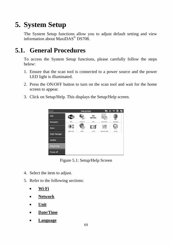
3. Click on Setup/Help. This displays the Setup/Help screen.
Figure 5.1: Setup/Help Screen
4. Select the item to adjust.
5. Refer to the following sections:
Wi-Fi
Network
Unit
Date/Time
Language
70
Backlight
Beep
Touch
Remote Desk
About
Printing
5.2. Wi-Fi
The Wi-Fi function allows you to use wireless network connection on the
scan tool.
1. Follow the instructions in the General Procedures to display the
Setup/Help screen.
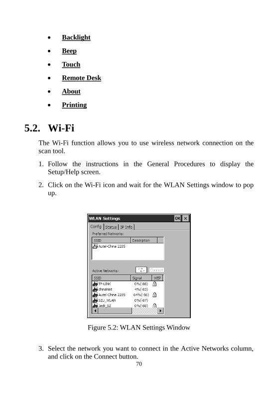
2. Click on the Wi-Fi icon and wait for the WLAN Settings window to pop
up.
Figure 5.2: WLAN Settings Window
3. Select the network you want to connect in the Active Networks column,
and click on the Connect button.
71
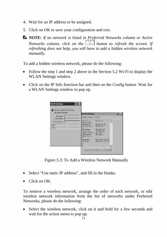
4. Wait for an IP address to be assigned.
5. Click on OK to save your configuration and exit.
NOTE: If no network is listed in Preferred Networks column or Active
Networks column, click on the button to refresh the screen. If refreshing does not help, you will have to add a hidden wireless network
manually.
To add a hidden wireless network, please do the following:
Follow the step 1 and step 2 above in the Section 5.2 Wi-Fi to display the
WLAN Settings window.
Click on the IP Info function bar and then on the Config button. Wait for
a WLAN Settings window to pop up.
Figure 5.3: To Add a Wireless Network Manually
Select “Use static IP address”, and fill in the blanks.
Click on OK.
To remove a wireless network, arrange the order of each network, or edit wireless network information from the list of networks under Preferred
Networks, please do the following:
Select the wireless network, click on it and hold for a few seconds and
wait for the action menu to pop up.
72
Select the action which you would accomplish.
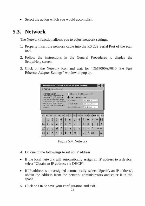
5.3. Network
The Network function allows you to adjust network settings.
1. Properly insert the network cable into the RS 232 Serial Port of the scan
tool.
2. Follow the instructions in the General Procedures to display the
Setup/Help screen.
3. Click on the Network icon and wait for “DM9000A/9010 ISA Fast
Ethernet Adapter Settings” window to pop up.
Figure 5.4: Network
4. Do one of the followings to set up IP address:
If the local network will automatically assign an IP address to a device,
select “Obtain an IP address via DHCP”.
If IP address is not assigned automatically, select “Specify an IP address”,
obtain the address from the network administrators and enter it in the
space.
5. Click on OK to save your configuration and exit.
73
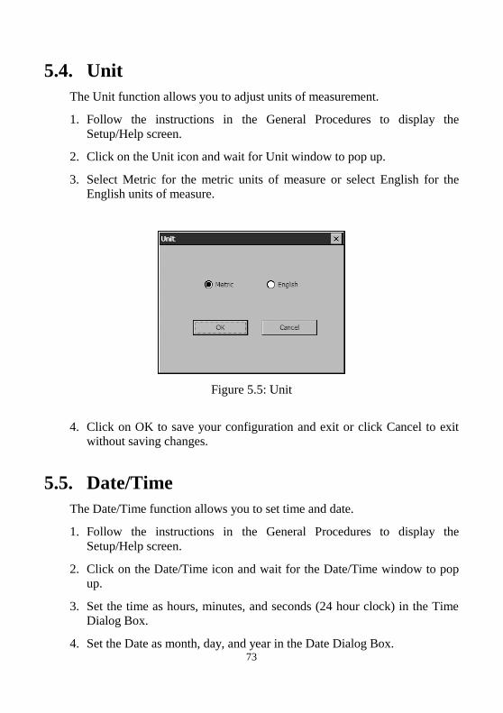
5.4. Unit
The Unit function allows you to adjust units of measurement.
1. Follow the instructions in the General Procedures to display the
Setup/Help screen.
2. Click on the Unit icon and wait for Unit window to pop up.
3. Select Metric for the metric units of measure or select English for the
English units of measure.
Figure 5.5: Unit
4. Click on OK to save your configuration and exit or click Cancel to exit
without saving changes.
5.5. Date/Time
The Date/Time function allows you to set time and date.
1. Follow the instructions in the General Procedures to display the
Setup/Help screen.
2. Click on the Date/Time icon and wait for the Date/Time window to pop
up.
3. Set the time as hours, minutes, and seconds (24 hour clock) in the Time
Dialog Box.
4. Set the Date as month, day, and year in the Date Dialog Box.
74
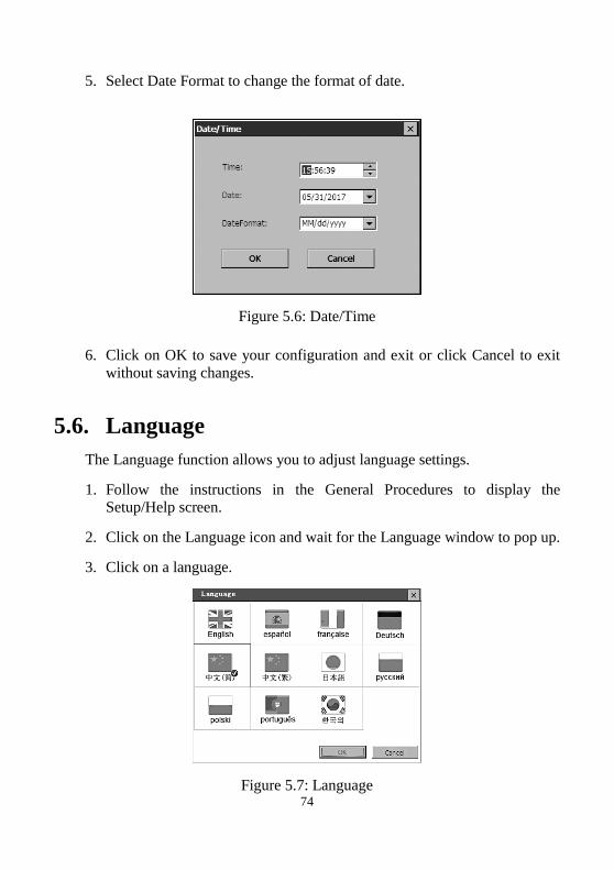
5. Select Date Format to change the format of date.
Figure 5.6: Date/Time
6. Click on OK to save your configuration and exit or click Cancel to exit
without saving changes.
5.6. Language
The Language function allows you to adjust language settings.
1. Follow the instructions in the General Procedures to display the
Setup/Help screen.
2. Click on the Language icon and wait for the Language window to pop up.
3. Click on a language.
Figure 5.7: Language
75
4. Click on OK to save your configuration and exit or Cancel to exit without
saving changes.
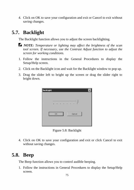
5.7. Backlight
The Backlight function allows you to adjust the screen backlighting.
NOTE: Temperature or lighting may affect the brightness of the scan tool screen. If necessary, use the Contrast Adjust function to adjust the
screen for working conditions.
1. Follow the instructions in the General Procedures to display the
Setup/Help screen.
2. Click on the Backlight icon and wait for the Backlight window to pop up.
3. Drag the slider left to bright up the screen or drag the slider right to
bright down.
Figure 5.8: Backlight
4. Click on OK to save your configuration and exit or click Cancel to exit
without saving changes.
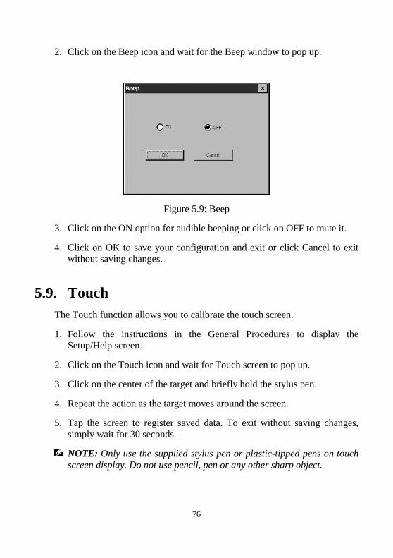
5.8. Beep
The Beep function allows you to control audible beeping.
1. Follow the instructions in General Procedures to display the Setup/Help
screen.
76
2. Click on the Beep icon and wait for the Beep window to pop up.
Figure 5.9: Beep
3. Click on the ON option for audible beeping or click on OFF to mute it.
4. Click on OK to save your configuration and exit or click Cancel to exit
without saving changes.
5.9. Touch
The Touch function allows you to calibrate the touch screen.
1. Follow the instructions in the General Procedures to display the
Setup/Help screen.
2. Click on the Touch icon and wait for Touch screen to pop up.
3. Click on the center of the target and briefly hold the stylus pen.
4. Repeat the action as the target moves around the screen.
5. Tap the screen to register saved data. To exit without saving changes,
simply wait for 30 seconds.
NOTE: Only use the supplied stylus pen or plastic-tipped pens on touch
screen display. Do not use pencil, pen or any other sharp object.
77
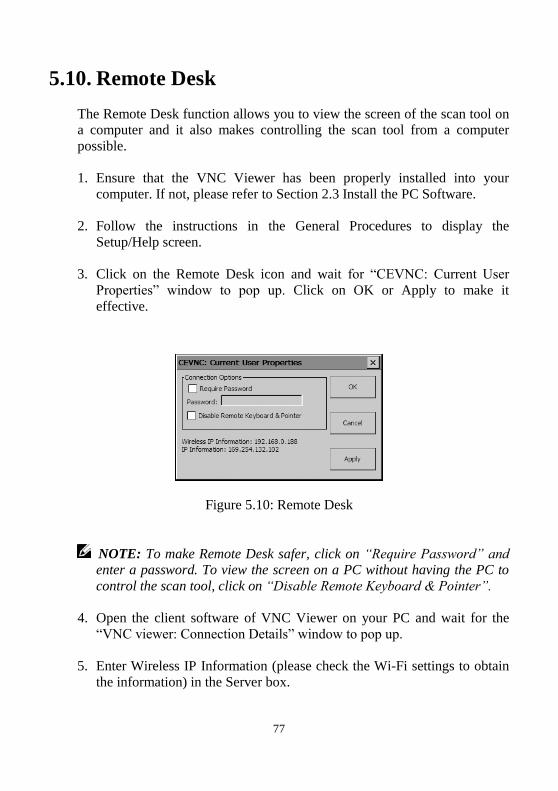
5.10. Remote Desk
The Remote Desk function allows you to view the screen of the scan tool on
a computer and it also makes controlling the scan tool from a computer
possible.
1. Ensure that the VNC Viewer has been properly installed into your
computer. If not, please refer to Section 2.3 Install the PC Software.
2. Follow the instructions in the General Procedures to display the
Setup/Help screen.
3. Click on the Remote Desk icon and wait for “CEVNC: Current User
Properties” window to pop up. Click on OK or Apply to make it
effective.
Figure 5.10: Remote Desk
NOTE: To make Remote Desk safer, click on “Require Password” and enter a password. To view the screen on a PC without having the PC to
control the scan tool, click on “Disable Remote Keyboard & Pointer”.
4. Open the client software of VNC Viewer on your PC and wait for the
“VNC viewer: Connection Details” window to pop up.
5. Enter Wireless IP Information (please check the Wi-Fi settings to obtain
the information) in the Server box.
78
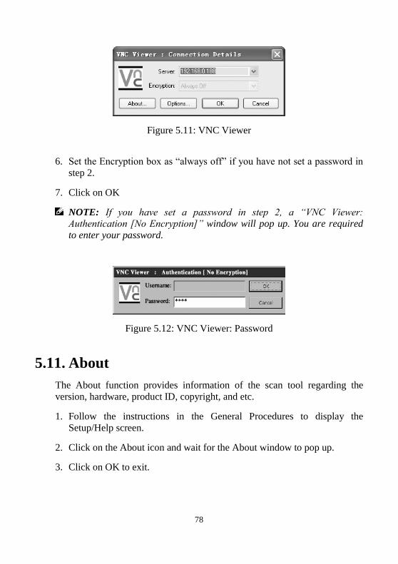
Figure 5.11: VNC Viewer
6. Set the Encryption box as “always off” if you have not set a password in
step 2.
7. Click on OK
NOTE: If you have set a password in step 2, a “VNC Viewer: Authentication [No Encryption]” window will pop up. You are required
to enter your password.
Figure 5.12: VNC Viewer: Password
5.11. About
The About function provides information of the scan tool regarding the
version, hardware, product ID, copyright, and etc.
1. Follow the instructions in the General Procedures to display the
Setup/Help screen.
2. Click on the About icon and wait for the About window to pop up.
3. Click on OK to exit.
79
6. Software Update
Autel frequently releases software updates that you can download. The
Update feature makes it very easy to determine and get exactly what you
need.
The Update allows you to update the scan tool software either through the
scan tool or via a computer.
6.1. Update the Scan Tool Software through the
Scan Tool
1. Ensure that the scan tool is connected to a power source and the power
LED light is illuminated.
2. Press the ON/OFF button to turn on the scan tool and wait for the home
screen to appear.
3. Connect the scan tool to the Internet. (Please refer to the Section 5.2
Wi-Fi or the Section 5.3 Network.)
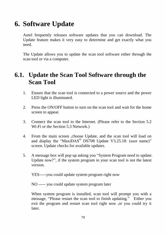
4. From the main screen ,choose Update, and the scan tool will load on
and display the “MaxiDAS® DS708 Update V3.25.18: (user name)”
screen. Update checks for available updates.
5. A message box will pop up asking you “System Program need to update.
Update now?”, if the system program in your scan tool is not the latest
version.
YES-----you could update system program right now
NO ----- you could update system program later
When system program is installed, scan tool will prompt you with a message, “Please restart the scan tool to finish updating.” Either you
exit the program and restart scan tool right now ,or you could try it
later.
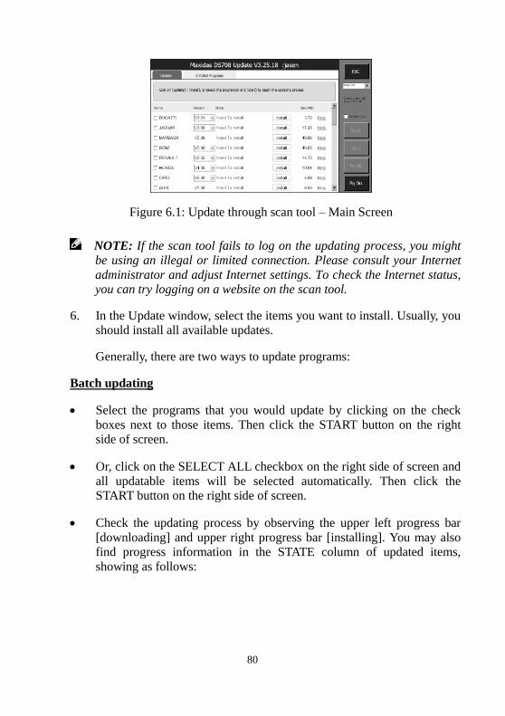
80
Figure 6.1: Update through scan tool – Main Screen
NOTE: If the scan tool fails to log on the updating process, you might be using an illegal or limited connection. Please consult your Internet
administrator and adjust Internet settings. To check the Internet status, you can try logging on a website on the scan tool.
6. In the Update window, select the items you want to install. Usually, you
should install all available updates.
Generally, there are two ways to update programs:
Batch updating
Select the programs that you would update by clicking on the check
boxes next to those items. Then click the START button on the right
side of screen.
Or, click on the SELECT ALL checkbox on the right side of screen and
all updatable items will be selected automatically. Then click the
START button on the right side of screen.
Check the updating process by observing the upper left progress bar
[downloading] and upper right progress bar [installing]. You may also
find progress information in the STATE column of updated items,
showing as follows:
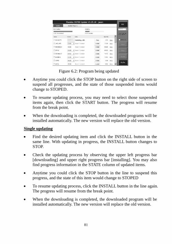
81
Figure 6.2: Program being updated
Anytime you could click the STOP button on the right side of screen to
suspend all progresses, and the state of those suspended items would
change to STOPED.
To resume updating process, you may need to select those suspended
items again, then click the START button. The progress will resume
from the break point.
When the downloading is completed, the downloaded programs will be
installed automatically. The new version will replace the old version.
Single updating
Find the desired updating item and click the INSTALL button in the
same line. With updating in progress, the INSTALL button changes to
STOP.
Check the updating process by observing the upper left progress bar
[downloading] and upper right progress bar [installing]. You may also
find progress information in the STATE column of updated items.
Anytime you could click the STOP button in the line to suspend this
progress, and the state of this item would change to STOPED
To resume updating process, click the INSTALL button in the line again.
The progress will resume from the break point.
When the downloading is completed, the downloaded program will be
installed automatically. The new version will replace the old version.
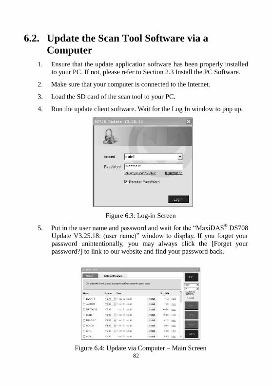
82
6.2. Update the Scan Tool Software via a
Computer
1. Ensure that the update application software has been properly installed
to your PC. If not, please refer to Section 2.3 Install the PC Software.
2. Make sure that your computer is connected to the Internet.
3. Load the SD card of the scan tool to your PC.
4. Run the update client software. Wait for the Log In window to pop up.
Figure 6.3: Log-in Screen
5. Put in the user name and password and wait for the “MaxiDAS® DS708
Update V3.25.18: (user name)” window to display. If you forget your
password unintentionally, you may always click the [Forget your
password?] to link to our website and find your password back.
Figure 6.4: Update via Computer – Main Screen
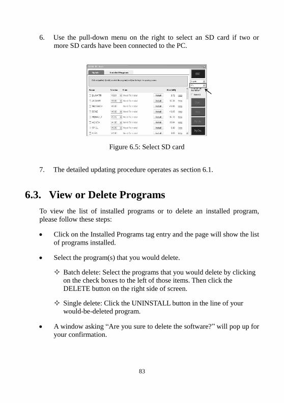
83
6. Use the pull-down menu on the right to select an SD card if two or
more SD cards have been connected to the PC.
Figure 6.5: Select SD card
7. The detailed updating procedure operates as section 6.1.
6.3. View or Delete Programs
To view the list of installed programs or to delete an installed program,
please follow these steps:
Click on the Installed Programs tag entry and the page will show the list
of programs installed.
Select the program(s) that you would delete.
Batch delete: Select the programs that you would delete by clicking
on the check boxes to the left of those items. Then click the
DELETE button on the right side of screen.
Single delete: Click the UNINSTALL button in the line of your
would-be-deleted program.
A window asking “Are you sure to delete the software?” will pop up for your confirmation.
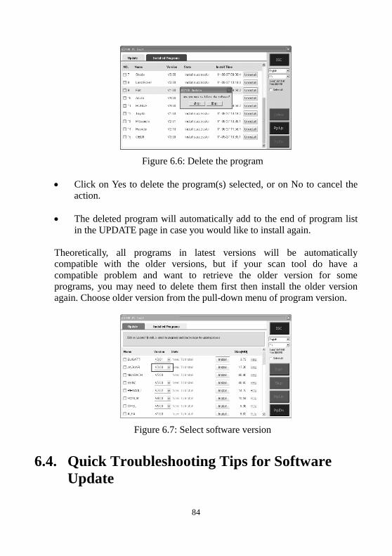
84
Figure 6.6: Delete the program
Click on Yes to delete the program(s) selected, or on No to cancel the
action.
The deleted program will automatically add to the end of program list
in the UPDATE page in case you would like to install again.
Theoretically, all programs in latest versions will be automatically
compatible with the older versions, but if your scan tool do have a
compatible problem and want to retrieve the older version for some
programs, you may need to delete them first then install the older version
again. Choose older version from the pull-down menu of program version.
Figure 6.7: Select software version
6.4. Quick Troubleshooting Tips for Software
Update
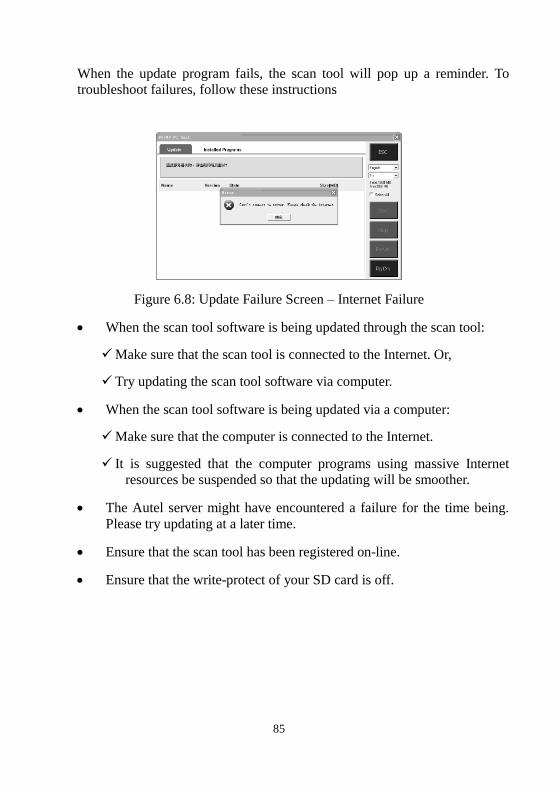
85
When the update program fails, the scan tool will pop up a reminder. To
troubleshoot failures, follow these instructions
Figure 6.8: Update Failure Screen – Internet Failure
When the scan tool software is being updated through the scan tool:
Make sure that the scan tool is connected to the Internet. Or,
Try updating the scan tool software via computer.
When the scan tool software is being updated via a computer:
Make sure that the computer is connected to the Internet.
It is suggested that the computer programs using massive Internet
resources be suspended so that the updating will be smoother.
The Autel server might have encountered a failure for the time being.
Please try updating at a later time.
Ensure that the scan tool has been registered on-line.
Ensure that the write-protect of your SD card is off.
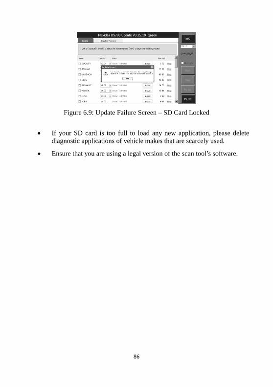
86
Figure 6.9: Update Failure Screen – SD Card Locked
If your SD card is too full to load any new application, please delete
diagnostic applications of vehicle makes that are scarcely used.
Ensure that you are using a legal version of the scan tool’s software.

87
7. Maintenance, Warranty & Service
7.1. Cleaning the Touch Screen
The touch screen can be cleaned with a soft cloth and alcohol or a mild
window cleaner.
IMPORTANT: Do not use any abrasive cleansers or automotive
chemicals on the touch screen.
7.2. Cleaning and Inspecting the Unit
When using the MaxiDAS® DS708 unit, make sure to do the following:
1. Check the housing, wiring, and adaptors for dirt and damage before and
after each use.
2. At the end of each working day, clean the MaxiDAS® DS708 housing,
wiring, and adapters with a clean damp cloth.
IMPORTANT: Do not use any abrasive cleansers or automotive
chemicals on the MaxiDAS®
DS708 unit.
7.3. Quick Troubleshooting Tips
1. Ensure that the scan tool is connected to a power source and the Power
LED light is illuminated.
2. Ensure that the SD card is inserted into the scan tool.
3. Ensure that the scan tool has been registered.
4. Ensure that the system software and diagnostic application software are
properly updated.
5. Ensure that the scan tool is connected to the Internet.
6. Check all cables, connections and indicators to see if the signal is being
received.
7. Do not use the scan tool beside microwave ovens, cordless phones and
some medical or scientific instruments to prevent signal interference.
8. Ensure that the computer installed with the PCLink software is connected
to a printer.
88
9. Ensure that the computer is connected to a network if any of the scan
tool’s functions are to be realized on the computer.
NOTE: If your problems persist, please contact Autel Tech Support or
your local selling agent.
7.4. Definitions of Navigation Buttons
The house icon appears in the upper left corner of the screen. Clicking
once leads to the home screen of the scan tool.
The question mark icon appears in the upper left corner of the screen.
Clicking once leads to the website of www.auteltech.com.
The camera icons appear in the upper right corner of the screen.
Clicking once leads to screen capture.
The Internet icon appears in the upper right corner of the screen.
Clicking once leads to the internet surfer.
The signal icon appears in the upper right corner of the screen. The icon
indicates the status of WLAN settings, and it is green when the scan
tool is connected to Wi-Fi.
The computer icon appears in the upper right corner of the screen. The
icon indicates the status of Ethernet. The red cross disappears when the
scan tool is connected to wired network.
The disc icon appears in the upper right corner of the screen. Clicking
once leads to the data logging menu.
The computer and radar icon appears in the upper right corner of the
screen. Clicking once leads to the remote desk settings. The red cross
disappears when the remote desk function is engaged.
7.5. Service Procedures
7.5.1. Technical Service

89
7.5.2. Repair Service
7.5.3. Order Information
Replacement and optional parts can be ordered directly from your Autel
authorized tool supplier.
Your order should include the following information:
Quantity
Part number
Item description

90
7.6. Limited One Year Warranty
Autel warrants to its customers that this product will be free from all defects
in materials and workmanship for a period of one (1) year from the date of the
original purchase, subject to the following terms and conditions:
1. The sole responsibility of Autel under the Warranty is limited to either the
repair or, at the option of Autel, replacement of the scan tool at no charge
with Proof of Purchase. The sales receipt may be used for this purpose.
2. This warranty does not apply to damages caused by improper use,
accident, flood, lightning, or if the product was altered or repaired by
anyone other than the Manufacturer’s Service Center.
3. Autel shall not be liable for any incidental or consequential damages
arising from the use, misuse, or mounting of the scan tool. Some states do
not allow limitations on how long an implied warranty lasts, so the above
limitations may not apply to you.
4. All information in this manual is based on the latest information available
at the time of publication and no warranty can be made for its accuracy or
completeness. Autel reserves the right to make changes at any time
without notice.