Embed Size (px)
Citation preview

Supplemental Files
Tutorial files on enclosed CD
3ds Max Design 2012®Autodesk
Fundamentals®
SDCP U B L I C A T I O N S
www.SDCpublications.comBetter Textbooks. Lower Prices.
Schroff Development Corporation

Visit our website to learn more about this and other books:
3–1
Chapter 3Basic Modeling Techniques
This chapter introduces:
Model with PrimitivesApplying TransformsSub-Object ModeReference Coordinate Systems and Transform CentersCloning and GroupingPoly Modeling with Graphite ToolsStatistics in Viewport

3–2
Basic Modeling Techniques
© Do not duplicate. 3–3
3.1 Model with Primitives
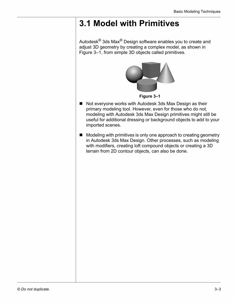
Autodesk® 3ds Max® Design software enables you to create and adjust 3D geometry by creating a complex model, as shown in Figure 3–1, from simple 3D objects called primitives.
Figure 3–1
Not everyone works with Autodesk 3ds Max Design as their primary modeling tool. However, even for those who do not, modeling with Autodesk 3ds Max Design primitives might still be useful for additional dressing or background objects to add to your imported scenes.
Modeling with primitives is only one approach to creating geometry in Autodesk 3ds Max Design. Other processes, such as modeling with modifiers, creating loft compound objects or creating a 3D terrain from 2D contour objects, can also be done.
Autodesk 3ds Max Design 2012 Fundamentals
3–4 © Do not duplicate.
Practice 3a Modeling with Primitives Estimated time for completion: 10 minutes.
In this practice you will model the base for the parking lot light fixtures. You will continue with this model in other practices.
1. Open Modeling with Primitives.max from your Class Files folder. If you get a dialog box that mentions a File Load: Mismatch, click
to accept the default values.
2. In the Command Panel, select the Create tab ( ). Click
(Geometry) and verify Standard Primitives displays in the drop-down list. In the Object Type rollout, click .
3. If the Keyboard Entry rollout is collapsed, click to expand it.
4. In the Keyboard Entry rollout leave the X, Y, Z coordinates at 0’0”. Set the Radius to 1’0” and the Height to 3’0”. Click . You can either enter the values directly in the respective fields or use the spinner arrows to increase or decrease the values.
5. Click (Zoom Extents) to get a closer look at the base. Note that it zooms into the cylinder in the Perspective viewport only, because that is the active viewport (yellow border).
6. With the cylinder still selected, in the Command Panel, select the
Modify tab ( ). At the top of the modifier list, in the name field, rename the object from Cylinder001 to LP Base.
Note: After creating an object, you cannot change the parameters in the Keyboard Entry rollout. Changing the parameters in the Keyboard Entry rollout
and clicking adds a second object. If you created another object, in
the Quick Access Toolbar, click once to undo the creation of second object.
After creating an object, use the Modify tab ( ) to change the parameters. Select the object if necessary, and select the Modify tab.Note: After entering a value in a field, either click in another edit field or press <Enter> to see its affect in the viewports.
Basic Modeling Techniques
© Do not duplicate. 3–5
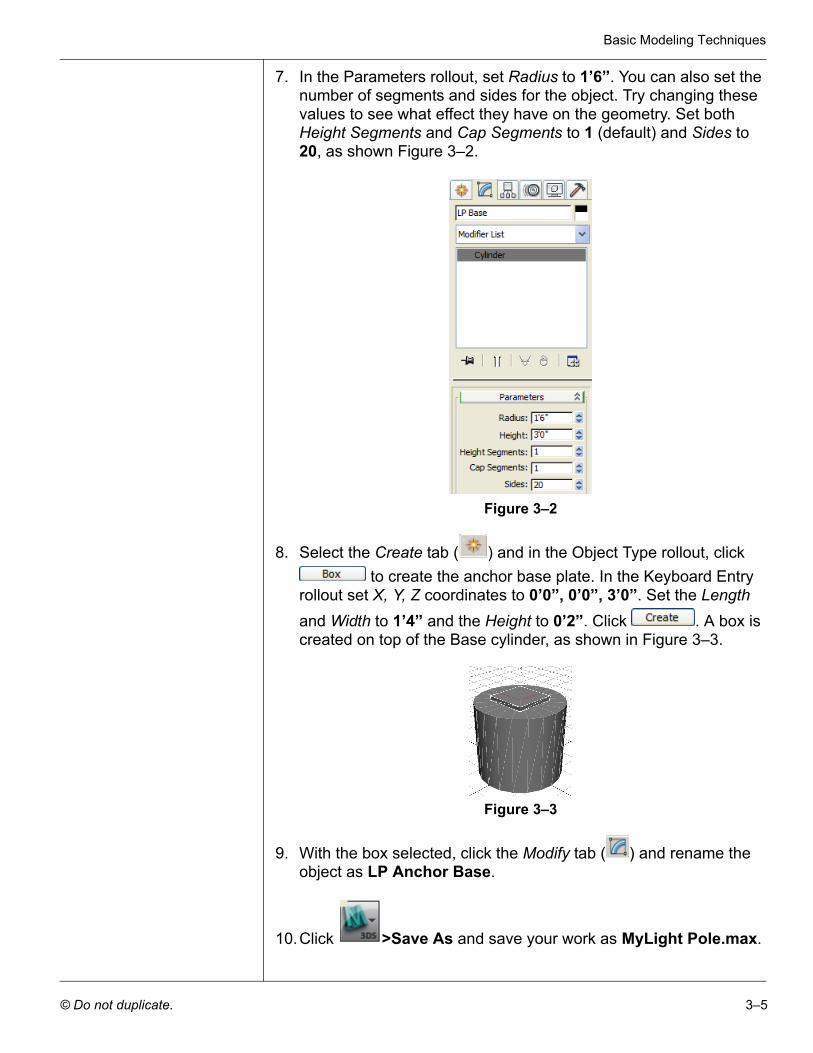
7. In the Parameters rollout, set Radius to 1’6”. You can also set the number of segments and sides for the object. Try changing these values to see what effect they have on the geometry. Set both Height Segments and Cap Segments to 1 (default) and Sides to 20, as shown Figure 3–2.
Figure 3–2
8. Select the Create tab ( ) and in the Object Type rollout, click to create the anchor base plate. In the Keyboard Entry
rollout set X, Y, Z coordinates to 0’0”, 0’0”, 3’0”. Set the Length and Width to 1’4” and the Height to 0’2”. Click . A box is created on top of the Base cylinder, as shown in Figure 3–3.
Figure 3–3
9. With the box selected, click the Modify tab ( ) and rename the object as LP Anchor Base.
10.Click >Save As and save your work as MyLight Pole.max.
Autodesk 3ds Max Design 2012 Fundamentals
3–6 © Do not duplicate.
3.2 Applying Transforms
Many CAD and 3D graphic programs consider Move, Rotate, and Scale as modify options similar to Stretch, Break, and Trim. However, in Autodesk 3ds Max Design there is a significant distinction between modifiers and transforms.
Modifiers add geometric and property alterations to objects. They are listed in the Modifier Stack and their parameter values are available for adjustment afterwards.
Transforms are used to translate (move) and scale objects in the scene. The three Autodesk 3ds Max Design transforms are Move, Rotate, and Scale. Transforms are conducted by accessing a transform mode and typing new values or graphically transforming objects on the screen.
Transforms are applied to objects after basic parameters and modifiers have been taken into account (except world-space modifiers). For example, if you scale a box, the Length parameter shown in the Modifier Stack does not take into account the effects of the scale transform.
An object can have any number of modifiers, but only has a single set of transform values at any time.
Transforms and almost all object and modifier parameters can be animated in Autodesk 3ds Max Design. For example, a walkthrough animation can be created using Move Transform to move the camera or its target or both.
Transform modes are initiated by selecting the required buttons in the Main toolbar or by using the Transform modes in the right-click quad menu.
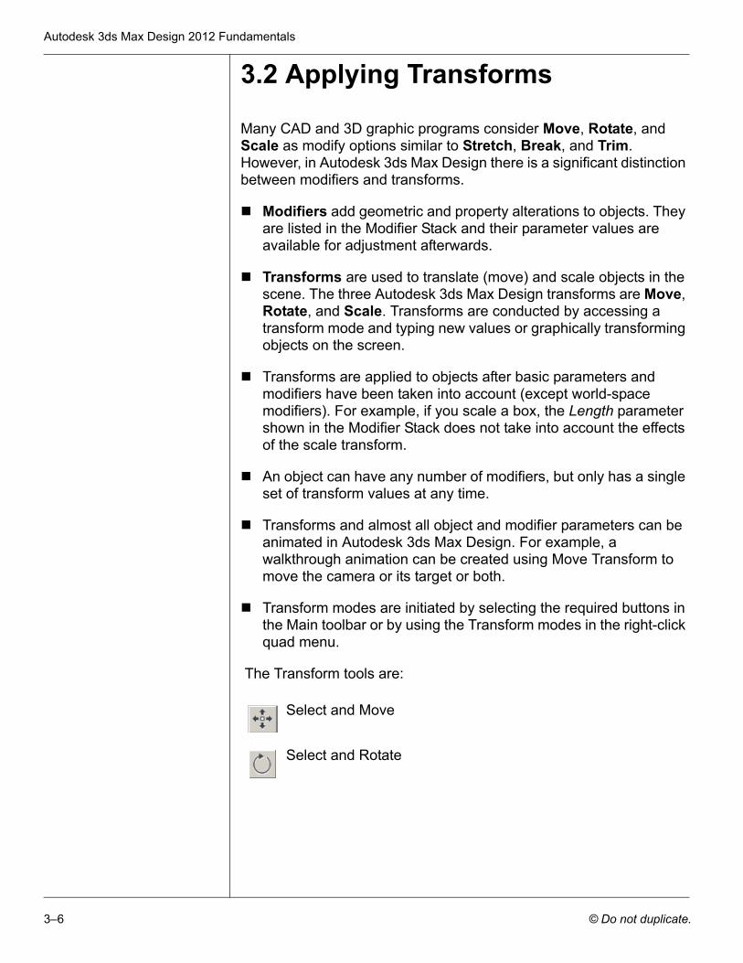
The Transform tools are:
Select and Move
Select and Rotate
Basic Modeling Techniques
© Do not duplicate. 3–7
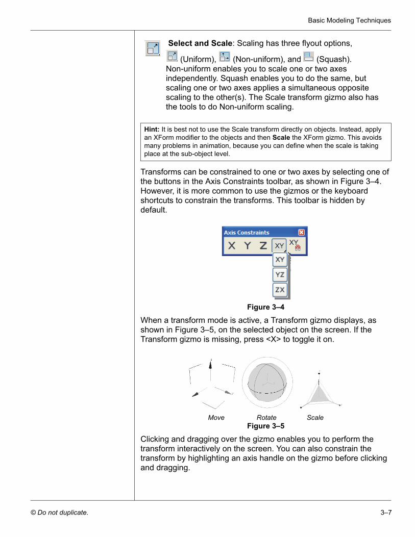
Transforms can be constrained to one or two axes by selecting one of the buttons in the Axis Constraints toolbar, as shown in Figure 3–4. However, it is more common to use the gizmos or the keyboard shortcuts to constrain the transforms. This toolbar is hidden by default.
Figure 3–4
When a transform mode is active, a Transform gizmo displays, as shown in Figure 3–5, on the selected object on the screen. If the Transform gizmo is missing, press <X> to toggle it on.
Move Rotate ScaleFigure 3–5
Clicking and dragging over the gizmo enables you to perform the transform interactively on the screen. You can also constrain the transform by highlighting an axis handle on the gizmo before clicking and dragging.
Select and Scale: Scaling has three flyout options,
(Uniform), (Non-uniform), and (Squash). Non-uniform enables you to scale one or two axes independently. Squash enables you to do the same, but scaling one or two axes applies a simultaneous opposite scaling to the other(s). The Scale transform gizmo also has the tools to do Non-uniform scaling.
Hint: It is best not to use the Scale transform directly on objects. Instead, apply an XForm modifier to the objects and then Scale the XForm gizmo. This avoids many problems in animation, because you can define when the scale is taking place at the sub-object level.
Autodesk 3ds Max Design 2012 Fundamentals
3–8 © Do not duplicate.
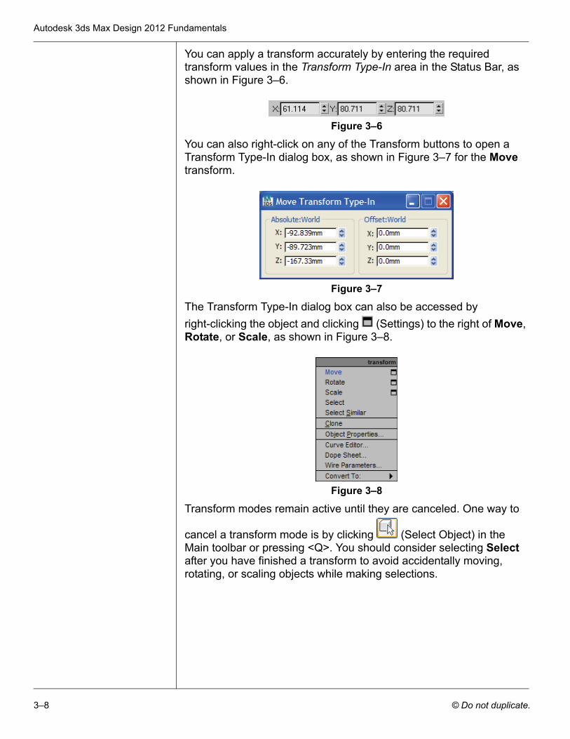
You can apply a transform accurately by entering the required transform values in the Transform Type-In area in the Status Bar, as shown in Figure 3–6.
Figure 3–6
You can also right-click on any of the Transform buttons to open a Transform Type-In dialog box, as shown in Figure 3–7 for the Move transform.
Figure 3–7
The Transform Type-In dialog box can also be accessed by right-clicking the object and clicking (Settings) to the right of Move, Rotate, or Scale, as shown in Figure 3–8.
Figure 3–8
Transform modes remain active until they are canceled. One way to
cancel a transform mode is by clicking (Select Object) in the Main toolbar or pressing <Q>. You should consider selecting Select after you have finished a transform to avoid accidentally moving, rotating, or scaling objects while making selections.
Basic Modeling Techniques
© Do not duplicate. 3–9
Practice 3b Modeling with Modifiers and Transforms
Estimated time for completion: 20-30 minutes.
In this practice you will refine the parking lot lighting fixture with Modifiers, then use Transforms to locate objects in the correct scene positions.
Task 1 - Extrude and Adjust the Light Pole.
To create the rectangular light pole, create a 2D cross-section shape and then extrude it into a 3D object. This approach is another way to create 3D geometry.
1. Continue working with the file created in the previous practice, MyLightPole.max. If you did not complete it, open Modeling with Modifiers and Transforms.max from your Class Files folder.
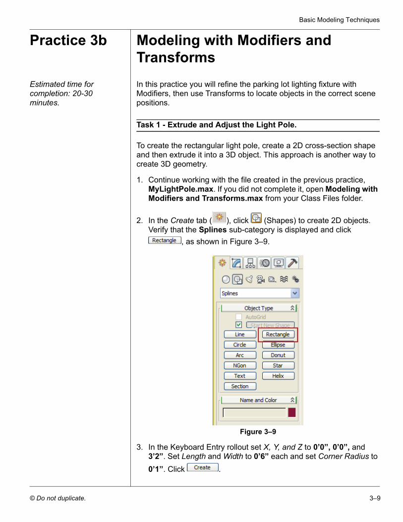
2. In the Create tab ( ), click (Shapes) to create 2D objects. Verify that the Splines sub-category is displayed and click
, as shown in Figure 3–9.
Figure 3–9
3. In the Keyboard Entry rollout set X, Y, and Z to 0’0”, 0’0”, and 3’2”. Set Length and Width to 0’6” each and set Corner Radius to 0’1”. Click .
Autodesk 3ds Max Design 2012 Fundamentals
3–10 © Do not duplicate.
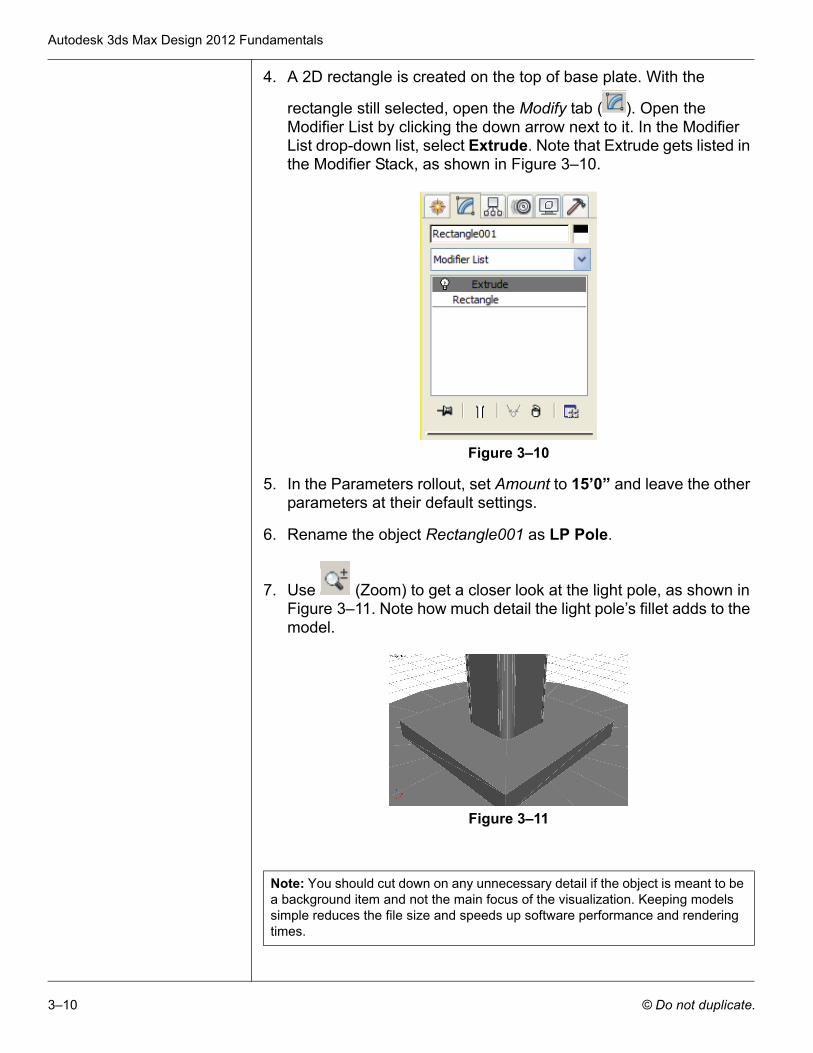
4. A 2D rectangle is created on the top of base plate. With the
rectangle still selected, open the Modify tab ( ). Open the Modifier List by clicking the down arrow next to it. In the Modifier List drop-down list, select Extrude. Note that Extrude gets listed in the Modifier Stack, as shown in Figure 3–10.
Figure 3–10
5. In the Parameters rollout, set Amount to 15’0” and leave the other parameters at their default settings.
6. Rename the object Rectangle001 as LP Pole.
7. Use (Zoom) to get a closer look at the light pole, as shown in Figure 3–11. Note how much detail the light pole’s fillet adds to the model.
Figure 3–11
Note: You should cut down on any unnecessary detail if the object is meant to be a background item and not the main focus of the visualization. Keeping models simple reduces the file size and speeds up software performance and rendering times.
Basic Modeling Techniques
© Do not duplicate. 3–11
The Extrude modifier is listed directly above the Rectangle object in the Modifier Stack. The rectangle’s parameters are still accessible and can be changed after the extrude is added.
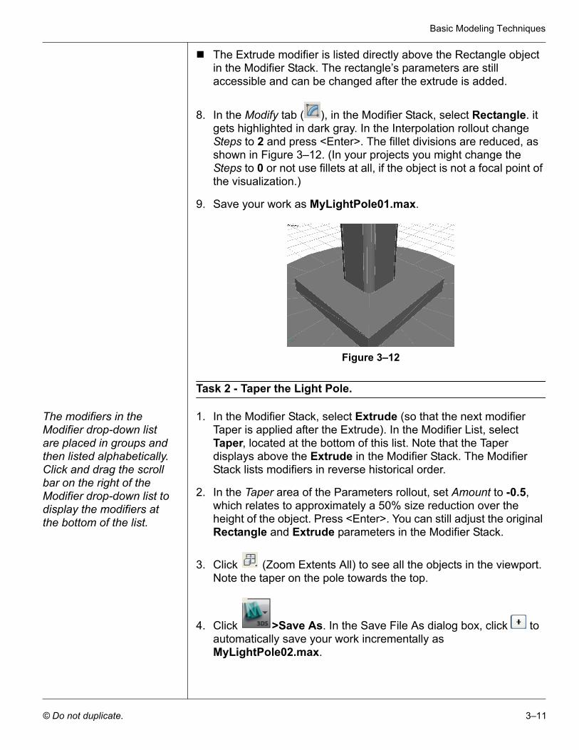
8. In the Modify tab ( ), in the Modifier Stack, select Rectangle. it gets highlighted in dark gray. In the Interpolation rollout change Steps to 2 and press <Enter>. The fillet divisions are reduced, as shown in Figure 3–12. (In your projects you might change the Steps to 0 or not use fillets at all, if the object is not a focal point of the visualization.)
9. Save your work as MyLightPole01.max.
Figure 3–12
Task 2 - Taper the Light Pole.
The modifiers in the Modifier drop-down list are placed in groups and then listed alphabetically. Click and drag the scroll bar on the right of the Modifier drop-down list to display the modifiers at the bottom of the list.
1. In the Modifier Stack, select Extrude (so that the next modifier Taper is applied after the Extrude). In the Modifier List, select Taper, located at the bottom of this list. Note that the Taper displays above the Extrude in the Modifier Stack. The Modifier Stack lists modifiers in reverse historical order.
2. In the Taper area of the Parameters rollout, set Amount to -0.5, which relates to approximately a 50% size reduction over the height of the object. Press <Enter>. You can still adjust the original Rectangle and Extrude parameters in the Modifier Stack.
3. Click (Zoom Extents All) to see all the objects in the viewport. Note the taper on the pole towards the top.
4. Click >Save As. In the Save File As dialog box, click to automatically save your work incrementally as MyLightPole02.max.
Autodesk 3ds Max Design 2012 Fundamentals
3–12 © Do not duplicate.
Task 3 - Create the Fixture Housing and Globe.
Previously you created primitives by keying in exact values in the Keyboard Entry rollout. Now you will roughly size the primitive shapes by clicking and dragging with the mouse in the viewport.
1. In the Create tab ( ), click (Geometry). In the Standard Primitives drop-down list, select Extended Primitives as a sub-category. In the Object Type rollout, click .
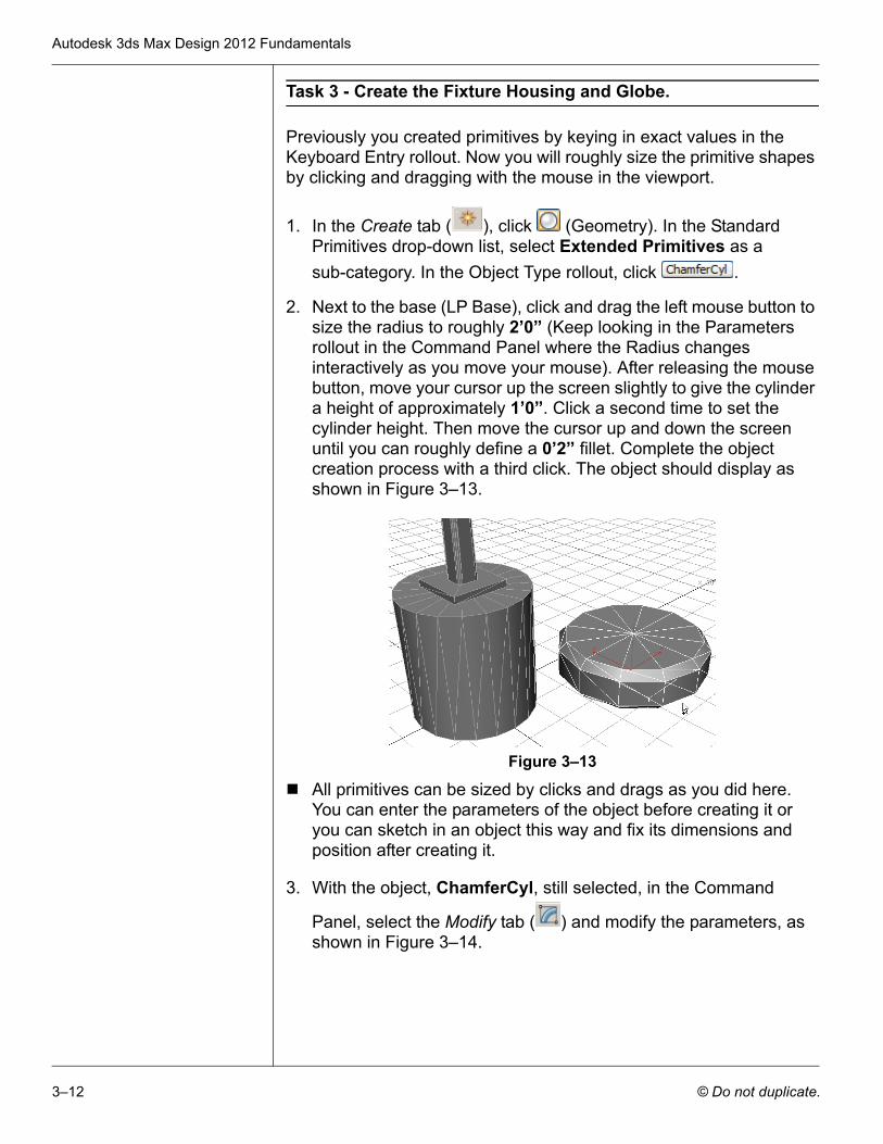
2. Next to the base (LP Base), click and drag the left mouse button to size the radius to roughly 2’0” (Keep looking in the Parameters rollout in the Command Panel where the Radius changes interactively as you move your mouse). After releasing the mouse button, move your cursor up the screen slightly to give the cylinder a height of approximately 1’0”. Click a second time to set the cylinder height. Then move the cursor up and down the screen until you can roughly define a 0’2” fillet. Complete the object creation process with a third click. The object should display as shown in Figure 3–13.
Figure 3–13
All primitives can be sized by clicks and drags as you did here. You can enter the parameters of the object before creating it or you can sketch in an object this way and fix its dimensions and position after creating it.
3. With the object, ChamferCyl, still selected, in the Command
Panel, select the Modify tab ( ) and modify the parameters, as shown in Figure 3–14.
Basic Modeling Techniques
© Do not duplicate. 3–13
Figure 3–14
4. Name the object LP Fixture Housing.
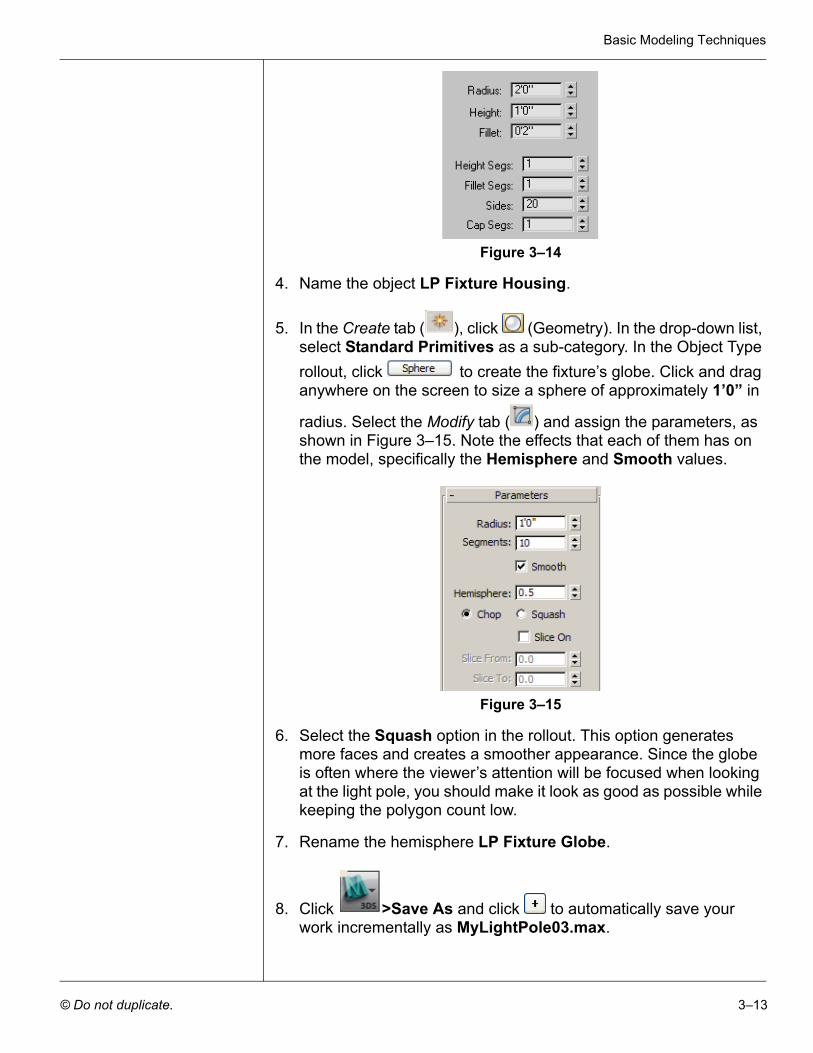
5. In the Create tab ( ), click (Geometry). In the drop-down list, select Standard Primitives as a sub-category. In the Object Type rollout, click to create the fixture’s globe. Click and drag anywhere on the screen to size a sphere of approximately 1’0” in
radius. Select the Modify tab ( ) and assign the parameters, as shown in Figure 3–15. Note the effects that each of them has on the model, specifically the Hemisphere and Smooth values.
Figure 3–15
6. Select the Squash option in the rollout. This option generates more faces and creates a smoother appearance. Since the globe is often where the viewer’s attention will be focused when looking at the light pole, you should make it look as good as possible while keeping the polygon count low.
7. Rename the hemisphere LP Fixture Globe.
8. Click >Save As and click to automatically save your work incrementally as MyLightPole03.max.
Autodesk 3ds Max Design 2012 Fundamentals
3–14 © Do not duplicate.
Task 4 - Use Transforms to Position Objects.
To complete this practice you will rotate and move the light pole fixture housing and globe into position.
1. Select the LP Fixture Housing (the chamfered cylinder) and in
the Main toolbar, click (Select and Move).
2. In the Main toolbar, set the Reference Coordinate System to
World by selecting it from the drop-down list and click (Use Pivot Point Center), as shown in Figure 3–16.
Figure 3–16
If the Transform gizmo is missing, press <X> to toggle it on.
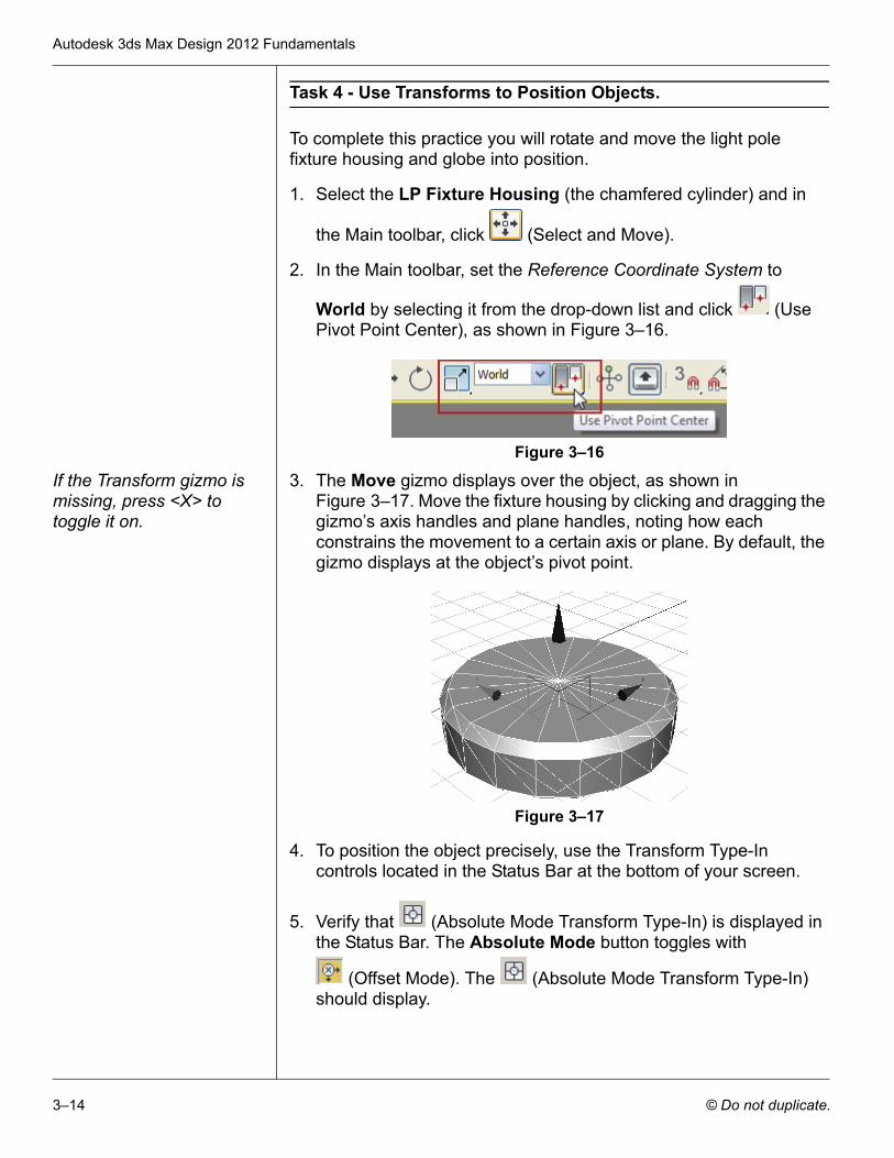
3. The Move gizmo displays over the object, as shown in Figure 3–17. Move the fixture housing by clicking and dragging the gizmo’s axis handles and plane handles, noting how each constrains the movement to a certain axis or plane. By default, the gizmo displays at the object’s pivot point.
Figure 3–17
4. To position the object precisely, use the Transform Type-In controls located in the Status Bar at the bottom of your screen.
5. Verify that (Absolute Mode Transform Type-In) is displayed in the Status Bar. The Absolute Mode button toggles with
(Offset Mode). The (Absolute Mode Transform Type-In) should display.
Basic Modeling Techniques
© Do not duplicate. 3–15
If the values are entered in Offset Mode, they are added to the current coordinates. Offset Mode is useful if you want to move an object a certain distance but are not sure what the resulting coordinates will be.
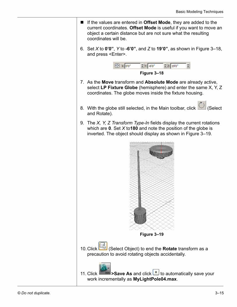
6. Set X to 0’0”, Y to -6’0”, and Z to 19’0”, as shown in Figure 3–18, and press <Enter>.
Figure 3–18
7. As the Move transform and Absolute Mode are already active, select LP Fixture Globe (hemisphere) and enter the same X, Y, Z coordinates. The globe moves inside the fixture housing.
8. With the globe still selected, in the Main toolbar, click (Select and Rotate).
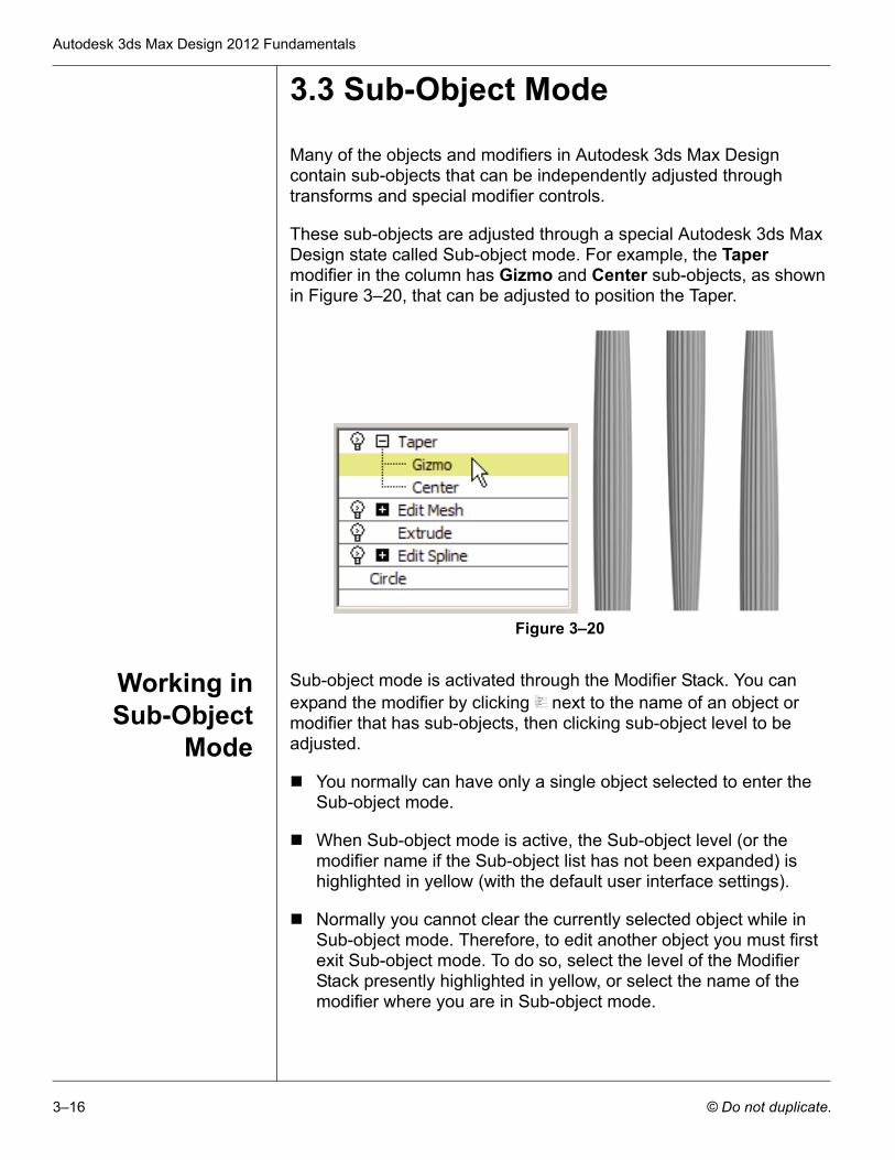
9. The X, Y, Z Transform Type-In fields display the current rotations which are 0. Set X to180 and note the position of the globe is inverted. The object should display as shown in Figure 3–19.
Figure 3–19
10.Click (Select Object) to end the Rotate transform as a precaution to avoid rotating objects accidentally.
11. Click >Save As and click to automatically save your work incrementally as MyLightPole04.max.
Autodesk 3ds Max Design 2012 Fundamentals
3–16 © Do not duplicate.
3.3 Sub-Object Mode
Many of the objects and modifiers in Autodesk 3ds Max Design contain sub-objects that can be independently adjusted through transforms and special modifier controls.
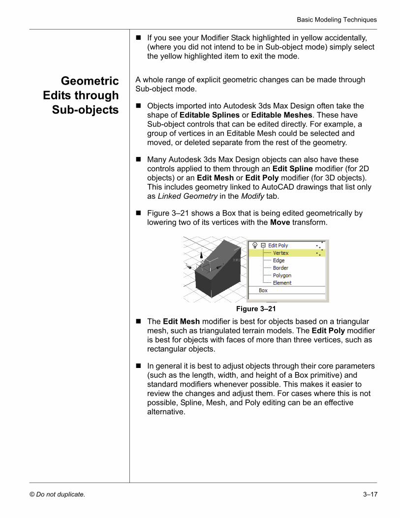
These sub-objects are adjusted through a special Autodesk 3ds Max Design state called Sub-object mode. For example, the Taper modifier in the column has Gizmo and Center sub-objects, as shown in Figure 3–20, that can be adjusted to position the Taper.
Figure 3–20
Working inSub-Object
Mode
Sub-object mode is activated through the Modifier Stack. You can expand the modifier by clicking next to the name of an object or modifier that has sub-objects, then clicking sub-object level to be adjusted.
You normally can have only a single object selected to enter the Sub-object mode.
When Sub-object mode is active, the Sub-object level (or the modifier name if the Sub-object list has not been expanded) is highlighted in yellow (with the default user interface settings).
Normally you cannot clear the currently selected object while in Sub-object mode. Therefore, to edit another object you must first exit Sub-object mode. To do so, select the level of the Modifier Stack presently highlighted in yellow, or select the name of the modifier where you are in Sub-object mode.
Basic Modeling Techniques
© Do not duplicate. 3–17
If you see your Modifier Stack highlighted in yellow accidentally, (where you did not intend to be in Sub-object mode) simply select the yellow highlighted item to exit the mode.
GeometricEdits through
Sub-objects
A whole range of explicit geometric changes can be made through Sub-object mode.
Objects imported into Autodesk 3ds Max Design often take the shape of Editable Splines or Editable Meshes. These have Sub-object controls that can be edited directly. For example, a group of vertices in an Editable Mesh could be selected and moved, or deleted separate from the rest of the geometry.
Many Autodesk 3ds Max Design objects can also have these controls applied to them through an Edit Spline modifier (for 2D objects) or an Edit Mesh or Edit Poly modifier (for 3D objects). This includes geometry linked to AutoCAD drawings that list only as Linked Geometry in the Modify tab.
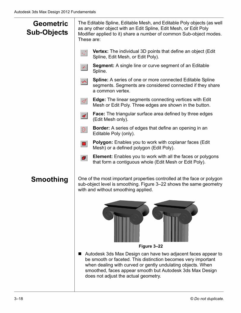
Figure 3–21 shows a Box that is being edited geometrically by lowering two of its vertices with the Move transform.
Figure 3–21
The Edit Mesh modifier is best for objects based on a triangular mesh, such as triangulated terrain models. The Edit Poly modifier is best for objects with faces of more than three vertices, such as rectangular objects.
In general it is best to adjust objects through their core parameters (such as the length, width, and height of a Box primitive) and standard modifiers whenever possible. This makes it easier to review the changes and adjust them. For cases where this is not possible, Spline, Mesh, and Poly editing can be an effective alternative.
Autodesk 3ds Max Design 2012 Fundamentals
3–18 © Do not duplicate.
GeometricSub-Objects
The Editable Spline, Editable Mesh, and Editable Poly objects (as well as any other object with an Edit Spline, Edit Mesh, or Edit Poly Modifier applied to it) share a number of common Sub-object modes. These are:
Smoothing One of the most important properties controlled at the face or polygon sub-object level is smoothing. Figure 3–22 shows the same geometry with and without smoothing applied.
Figure 3–22
Autodesk 3ds Max Design can have two adjacent faces appear to be smooth or faceted. This distinction becomes very important when dealing with curved or gently undulating objects. When smoothed, faces appear smooth but Autodesk 3ds Max Design does not adjust the actual geometry.
Vertex: The individual 3D points that define an object (Edit Spline, Edit Mesh, or Edit Poly).
Segment: A single line or curve segment of an Editable Spline.
Spline: A series of one or more connected Editable Spline segments. Segments are considered connected if they share a common vertex.
Edge: The linear segments connecting vertices with Edit Mesh or Edit Poly. Three edges are shown in the button.
Face: The triangular surface area defined by three edges (Edit Mesh only).
Border: A series of edges that define an opening in an Editable Poly (only).
Polygon: Enables you to work with coplanar faces (Edit Mesh) or a defined polygon (Edit Poly).
Element: Enables you to work with all the faces or polygons that form a contiguous whole (Edit Mesh or Edit Poly).
Basic Modeling Techniques
© Do not duplicate. 3–19
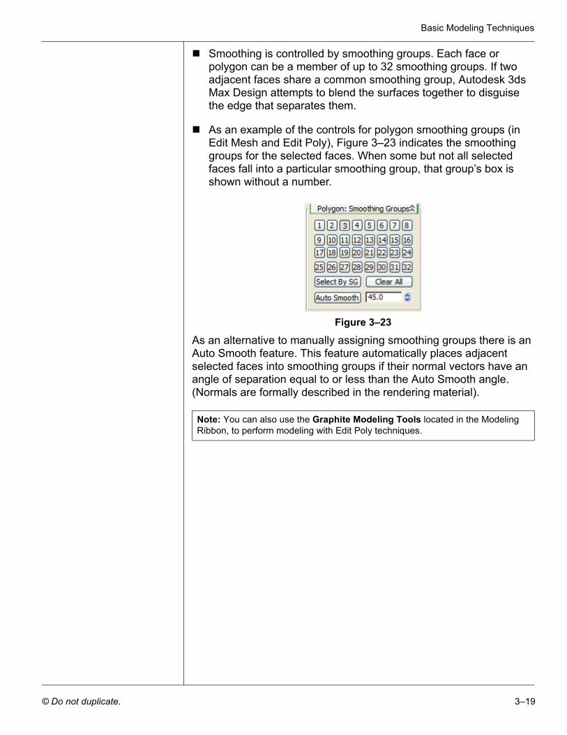
Smoothing is controlled by smoothing groups. Each face or polygon can be a member of up to 32 smoothing groups. If two adjacent faces share a common smoothing group, Autodesk 3ds Max Design attempts to blend the surfaces together to disguise the edge that separates them.
As an example of the controls for polygon smoothing groups (in Edit Mesh and Edit Poly), Figure 3–23 indicates the smoothing groups for the selected faces. When some but not all selected faces fall into a particular smoothing group, that group’s box is shown without a number.
Figure 3–23
As an alternative to manually assigning smoothing groups there is an Auto Smooth feature. This feature automatically places adjacent selected faces into smoothing groups if their normal vectors have an angle of separation equal to or less than the Auto Smooth angle. (Normals are formally described in the rendering material).
Note: You can also use the Graphite Modeling Tools located in the Modeling Ribbon, to perform modeling with Edit Poly techniques.
Autodesk 3ds Max Design 2012 Fundamentals
3–20 © Do not duplicate.
Practice 3c Modeling with Edit Poly in Sub-Object Mode
Estimated time for completion: 10 minutes.
In this practice you will add some detail to the concrete base of the light pole by chamfering (beveling) the outside top of the cylinder.
1. Continue with the file created in the previous practice MyLightPole04.max. If you did not complete it, open Modeling with Edit Poly in Sub-Object Mode.max from your Class Files folder.
2. Select LP Base and click (Zoom Extents Selected).
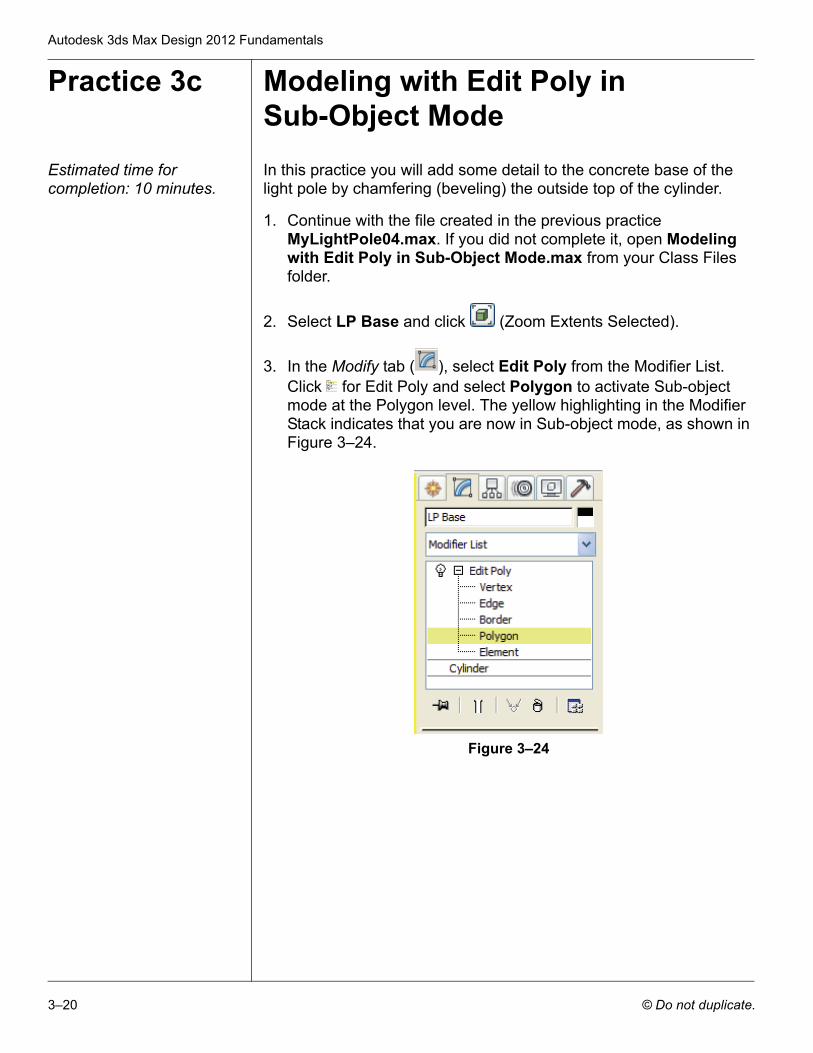
3. In the Modify tab ( ), select Edit Poly from the Modifier List. Click for Edit Poly and select Polygon to activate Sub-object mode at the Polygon level. The yellow highlighting in the Modifier Stack indicates that you are now in Sub-object mode, as shown in Figure 3–24.
Figure 3–24
Basic Modeling Techniques
© Do not duplicate. 3–21
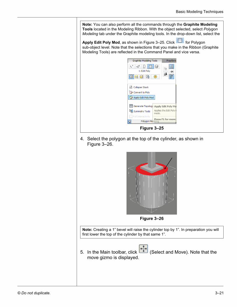
4. Select the polygon at the top of the cylinder, as shown in Figure 3–26.
Figure 3–26
5. In the Main toolbar, click (Select and Move). Note that the move gizmo is displayed.
Note: You can also perform all the commands through the Graphite Modeling Tools located in the Modeling Ribbon. With the object selected, select Polygon Modeling tab under the Graphite modeling tools. In the drop-down list, select the
Apply Edit Poly Mod, as shown in Figure 3–25. Click for Polygon sub-object level. Note that the selections that you make in the Ribbon (Graphite Modeling Tools) are reflected in the Command Panel and vice versa.
Figure 3–25
Note: Creating a 1” bevel will raise the cylinder top by 1”. In preparation you will first lower the top of the cylinder by that same 1”.
Autodesk 3ds Max Design 2012 Fundamentals
3–22 © Do not duplicate.
6. In the Status Bar, click (Absolute Mode Transform) to change
into (Offset Mode Transform) and set Z to -0’1” and press <Enter>. The cylinder geometry is adjusted.
7. In the Command Panel, in the Edit Polygons rollout, next to , click (Settings), as shown in Figure 3–27. You might
have to scroll down to locate this rollout.
Figure 3–27
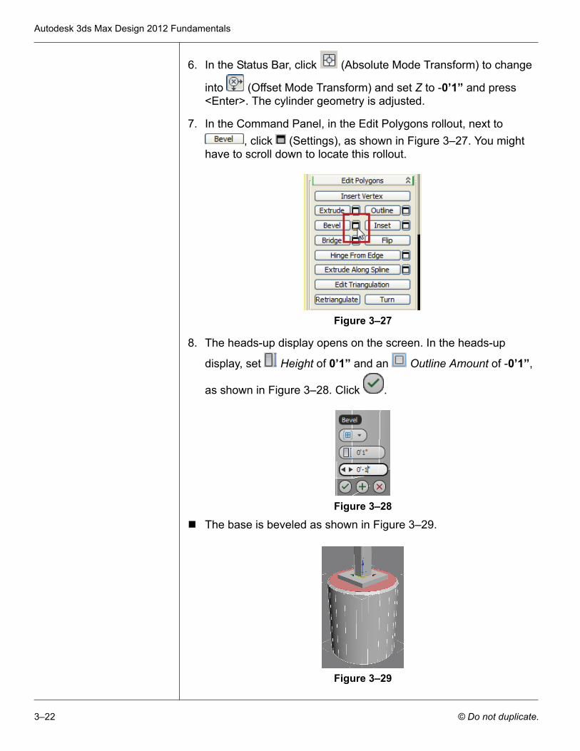
8. The heads-up display opens on the screen. In the heads-up
display, set Height of 0’1” and an Outline Amount of -0’1”,
as shown in Figure 3–28. Click .
Figure 3–28
The base is beveled as shown in Figure 3–29.
Figure 3–29
Basic Modeling Techniques
© Do not duplicate. 3–23
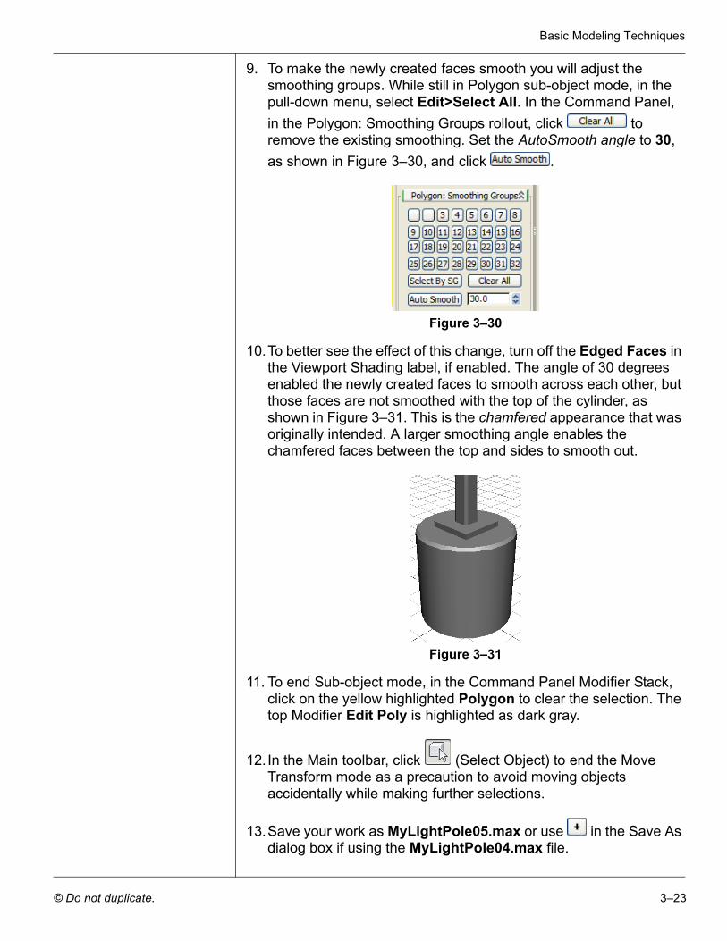
9. To make the newly created faces smooth you will adjust the smoothing groups. While still in Polygon sub-object mode, in the pull-down menu, select Edit>Select All. In the Command Panel, in the Polygon: Smoothing Groups rollout, click to remove the existing smoothing. Set the AutoSmooth angle to 30, as shown in Figure 3–30, and click .
Figure 3–30
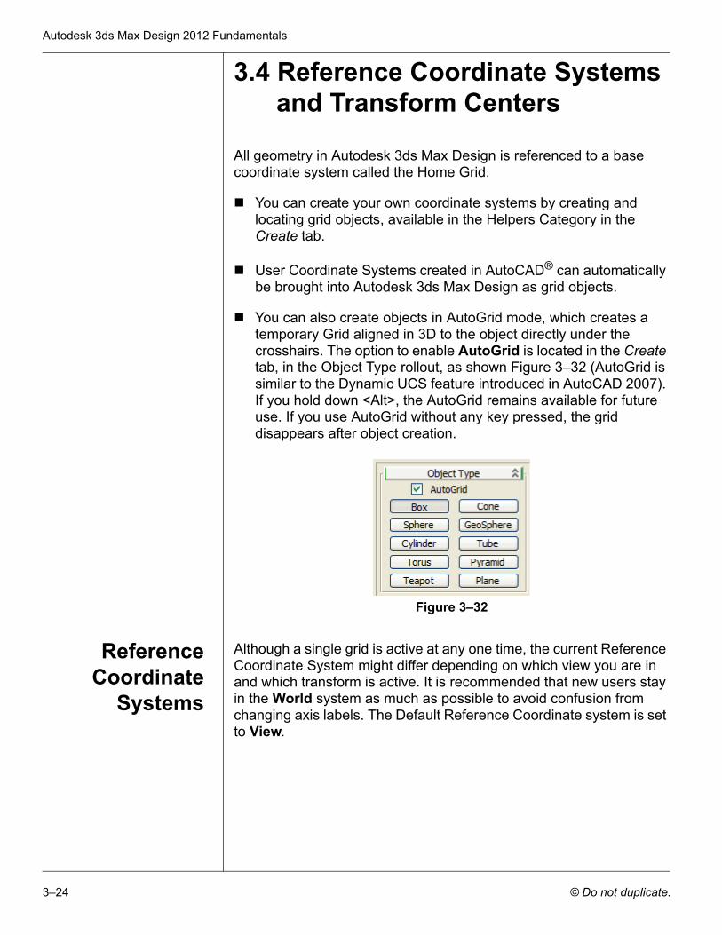
10.To better see the effect of this change, turn off the Edged Faces in the Viewport Shading label, if enabled. The angle of 30 degrees enabled the newly created faces to smooth across each other, but those faces are not smoothed with the top of the cylinder, as shown in Figure 3–31. This is the chamfered appearance that was originally intended. A larger smoothing angle enables the chamfered faces between the top and sides to smooth out.
Figure 3–31
11. To end Sub-object mode, in the Command Panel Modifier Stack, click on the yellow highlighted Polygon to clear the selection. The top Modifier Edit Poly is highlighted as dark gray.
12. In the Main toolbar, click (Select Object) to end the Move Transform mode as a precaution to avoid moving objects accidentally while making further selections.
13.Save your work as MyLightPole05.max or use in the Save As dialog box if using the MyLightPole04.max file.
Autodesk 3ds Max Design 2012 Fundamentals
3–24 © Do not duplicate.
3.4 Reference Coordinate Systems and Transform Centers
All geometry in Autodesk 3ds Max Design is referenced to a base coordinate system called the Home Grid.
You can create your own coordinate systems by creating and locating grid objects, available in the Helpers Category in the Create tab.
User Coordinate Systems created in AutoCAD® can automatically be brought into Autodesk 3ds Max Design as grid objects.
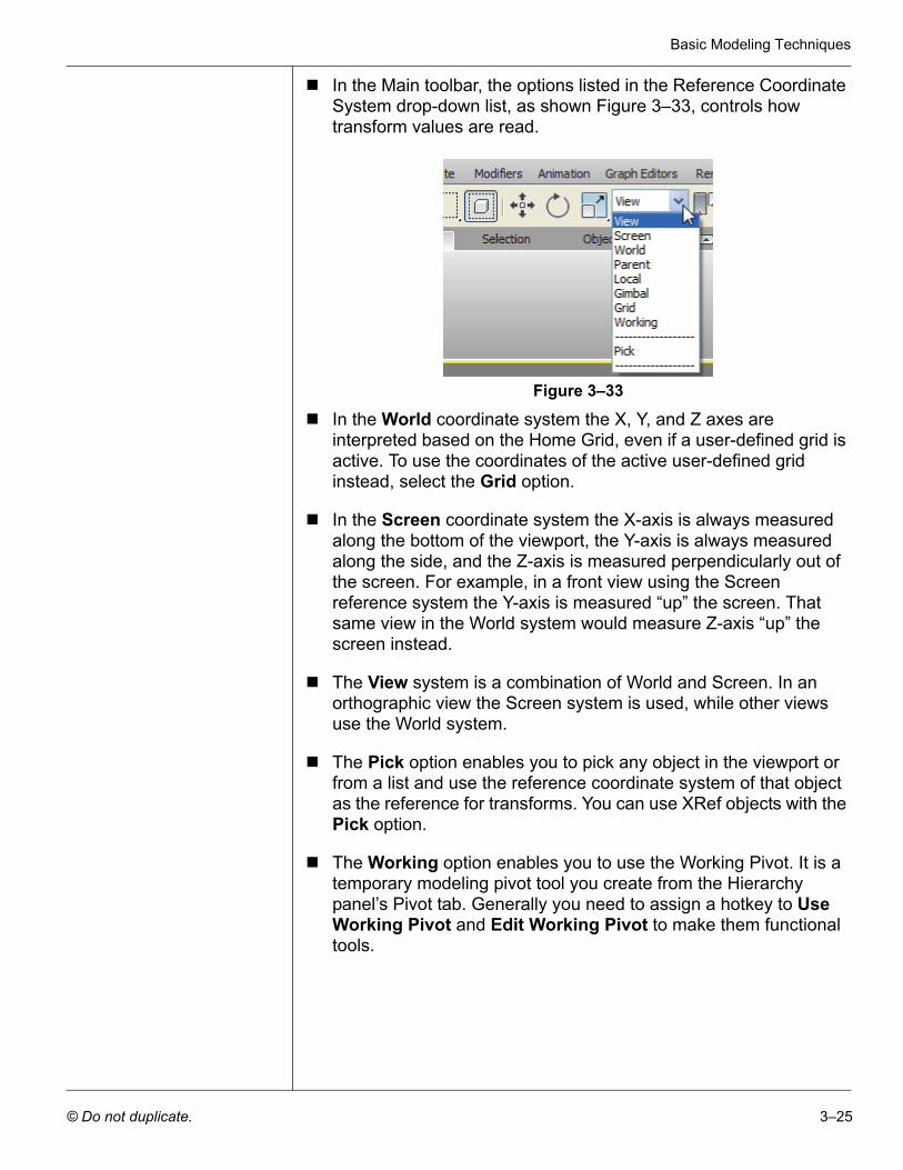
You can also create objects in AutoGrid mode, which creates a temporary Grid aligned in 3D to the object directly under the crosshairs. The option to enable AutoGrid is located in the Create tab, in the Object Type rollout, as shown Figure 3–32 (AutoGrid is similar to the Dynamic UCS feature introduced in AutoCAD 2007). If you hold down <Alt>, the AutoGrid remains available for future use. If you use AutoGrid without any key pressed, the grid disappears after object creation.
Figure 3–32
ReferenceCoordinate
Systems
Although a single grid is active at any one time, the current Reference Coordinate System might differ depending on which view you are in and which transform is active. It is recommended that new users stay in the World system as much as possible to avoid confusion from changing axis labels. The Default Reference Coordinate system is set to View.
Basic Modeling Techniques
© Do not duplicate. 3–25
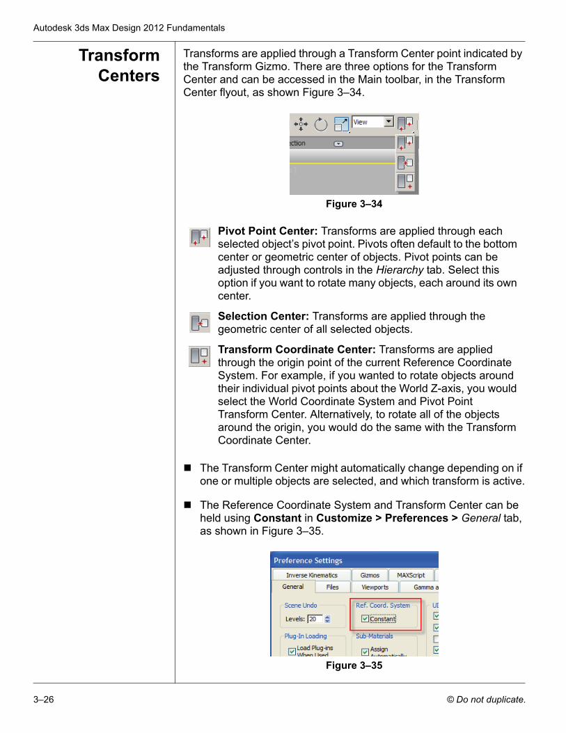
In the Main toolbar, the options listed in the Reference Coordinate System drop-down list, as shown Figure 3–33, controls how transform values are read.
Figure 3–33
In the World coordinate system the X, Y, and Z axes are interpreted based on the Home Grid, even if a user-defined grid is active. To use the coordinates of the active user-defined grid instead, select the Grid option.
In the Screen coordinate system the X-axis is always measured along the bottom of the viewport, the Y-axis is always measured along the side, and the Z-axis is measured perpendicularly out of the screen. For example, in a front view using the Screen reference system the Y-axis is measured “up” the screen. That same view in the World system would measure Z-axis “up” the screen instead.
The View system is a combination of World and Screen. In an orthographic view the Screen system is used, while other views use the World system.
The Pick option enables you to pick any object in the viewport or from a list and use the reference coordinate system of that object as the reference for transforms. You can use XRef objects with the Pick option.
The Working option enables you to use the Working Pivot. It is a temporary modeling pivot tool you create from the Hierarchy panel’s Pivot tab. Generally you need to assign a hotkey to Use Working Pivot and Edit Working Pivot to make them functional tools.
Autodesk 3ds Max Design 2012 Fundamentals
3–26 © Do not duplicate.
TransformCenters
Transforms are applied through a Transform Center point indicated by the Transform Gizmo. There are three options for the Transform Center and can be accessed in the Main toolbar, in the Transform Center flyout, as shown Figure 3–34.
Figure 3–34
The Transform Center might automatically change depending on if one or multiple objects are selected, and which transform is active.
The Reference Coordinate System and Transform Center can be held using Constant in Customize > Preferences > General tab, as shown in Figure 3–35.
Figure 3–35
Pivot Point Center: Transforms are applied through each selected object’s pivot point. Pivots often default to the bottom center or geometric center of objects. Pivot points can be adjusted through controls in the Hierarchy tab. Select this option if you want to rotate many objects, each around its own center.
Selection Center: Transforms are applied through the geometric center of all selected objects.
Transform Coordinate Center: Transforms are applied through the origin point of the current Reference Coordinate System. For example, if you wanted to rotate objects around their individual pivot points about the World Z-axis, you would select the World Coordinate System and Pivot Point Transform Center. Alternatively, to rotate all of the objects around the origin, you would do the same with the Transform Coordinate Center.
Basic Modeling Techniques
© Do not duplicate. 3–27
Practice 3d Modeling with Coordinate SystemsEstimated time for completion: 10 minutes.
For the next step in the Light Pole model you will add the Light Pole Mounting Arm.
1. Continue with the file MyLightPole05.max created in the previous practice. If you did not complete it, open Modeling with Coordinate Systems.max from your Class Files folder.
2. Click (Maximize Viewport) to display multiple viewports.
3. The Front viewport is unavailable. Click on one of the Top viewports, click in the Point of View label (Top), and select Front. Make sure that the Front viewport is active.
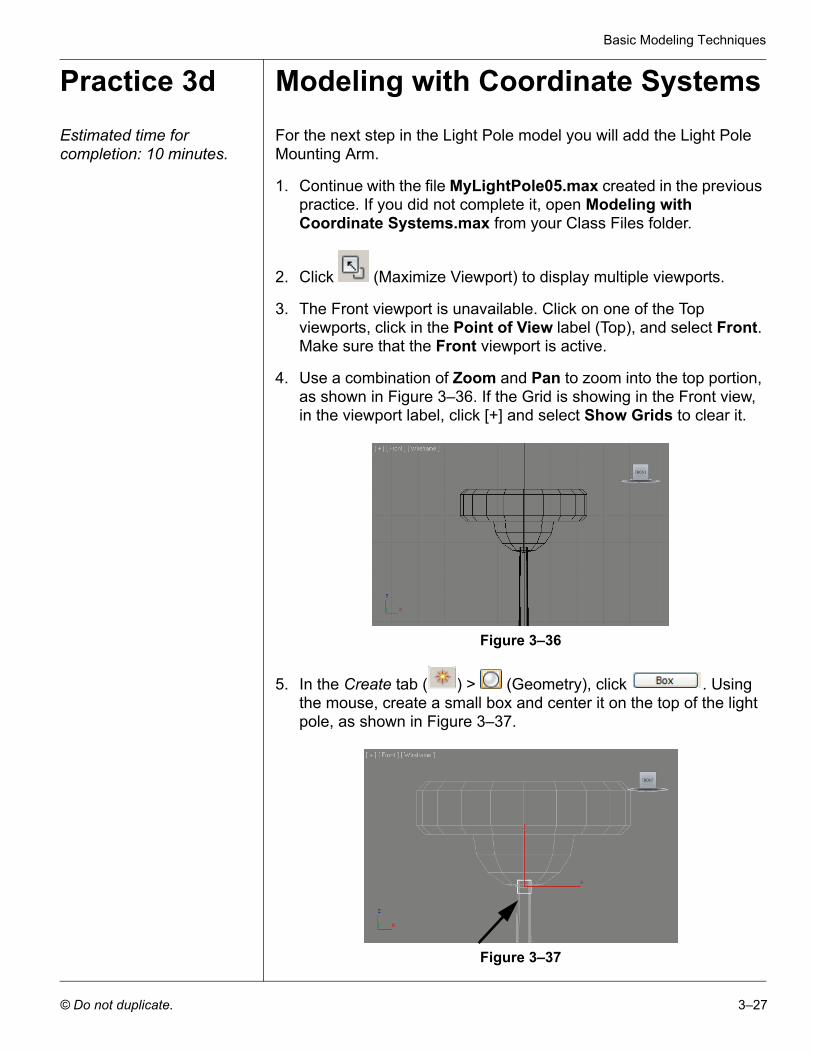
4. Use a combination of Zoom and Pan to zoom into the top portion, as shown in Figure 3–36. If the Grid is showing in the Front view, in the viewport label, click [+] and select Show Grids to clear it.
Figure 3–36
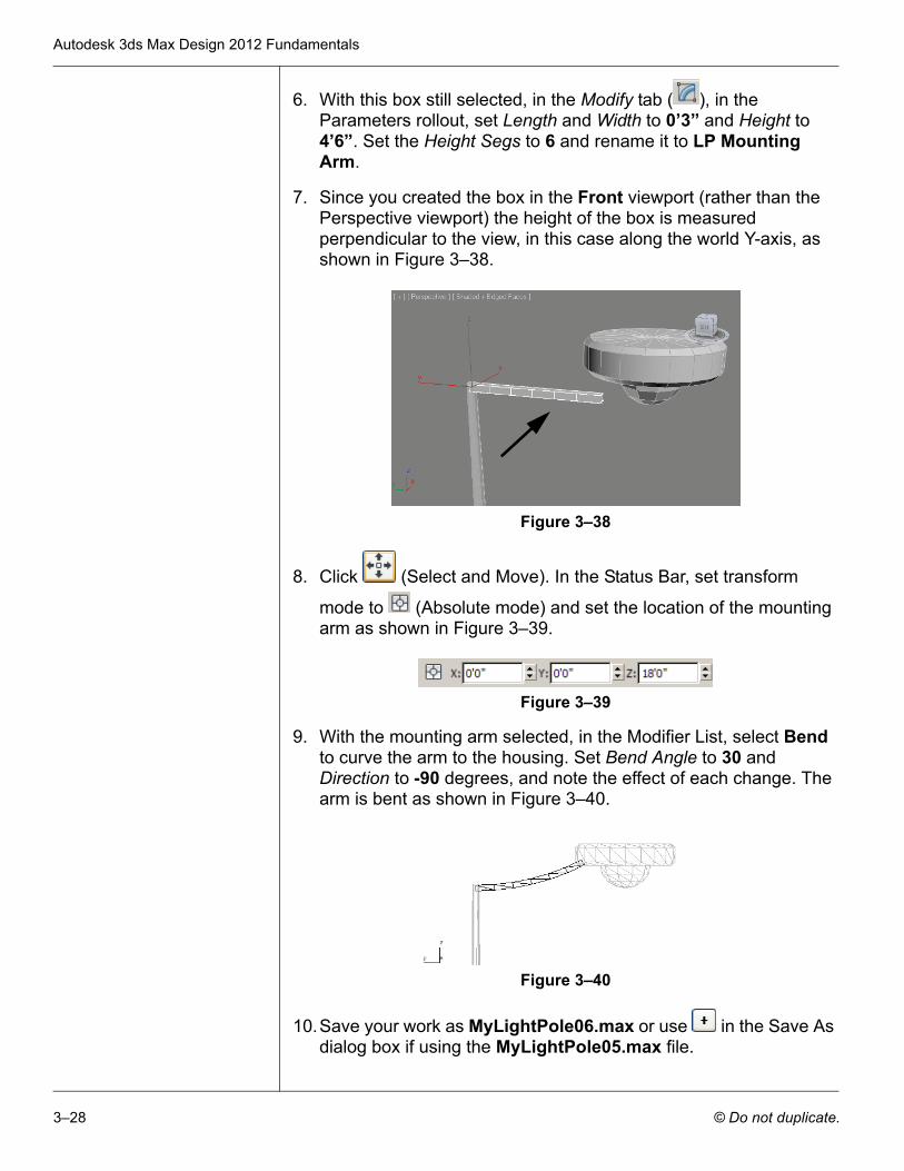
5. In the Create tab ( ) > (Geometry), click . Using the mouse, create a small box and center it on the top of the light pole, as shown in Figure 3–37.
Figure 3–37
Autodesk 3ds Max Design 2012 Fundamentals
3–28 © Do not duplicate.
6. With this box still selected, in the Modify tab ( ), in the Parameters rollout, set Length and Width to 0’3” and Height to 4’6”. Set the Height Segs to 6 and rename it to LP Mounting Arm.
7. Since you created the box in the Front viewport (rather than the Perspective viewport) the height of the box is measured perpendicular to the view, in this case along the world Y-axis, as shown in Figure 3–38.
Figure 3–38
8. Click (Select and Move). In the Status Bar, set transform
mode to (Absolute mode) and set the location of the mounting arm as shown in Figure 3–39.
Figure 3–39
9. With the mounting arm selected, in the Modifier List, select Bend to curve the arm to the housing. Set Bend Angle to 30 and Direction to -90 degrees, and note the effect of each change. The arm is bent as shown in Figure 3–40.
Figure 3–40
10.Save your work as MyLightPole06.max or use in the Save As dialog box if using the MyLightPole05.max file.
Basic Modeling Techniques
© Do not duplicate. 3–29
3.5 Cloning and Grouping
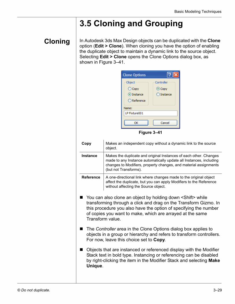
Cloning In Autodesk 3ds Max Design objects can be duplicated with the Clone option (Edit > Clone). When cloning you have the option of enabling the duplicate object to maintain a dynamic link to the source object. Selecting Edit > Clone opens the Clone Options dialog box, as shown in Figure 3–41.
Figure 3–41
You can also clone an object by holding down <Shift> while transforming through a click and drag on the Transform Gizmo. In this procedure you also have the option of specifying the number of copies you want to make, which are arrayed at the same Transform value.
The Controller area in the Clone Options dialog box applies to objects in a group or hierarchy and refers to transform controllers. For now, leave this choice set to Copy.
Objects that are instanced or referenced display with the Modifier Stack text in bold type. Instancing or referencing can be disabled by right-clicking the item in the Modifier Stack and selecting Make Unique.
Copy Makes an independent copy without a dynamic link to the source object.
Instance Makes the duplicate and original Instances of each other. Changes made to any Instance automatically update all Instances, including changes to Modifiers, property changes, and material assignments (but not Transforms).
Reference A one-directional link where changes made to the original object affect the duplicate, but you can apply Modifiers to the Reference without affecting the Source object.
Autodesk 3ds Max Design 2012 Fundamentals
3–30 © Do not duplicate.
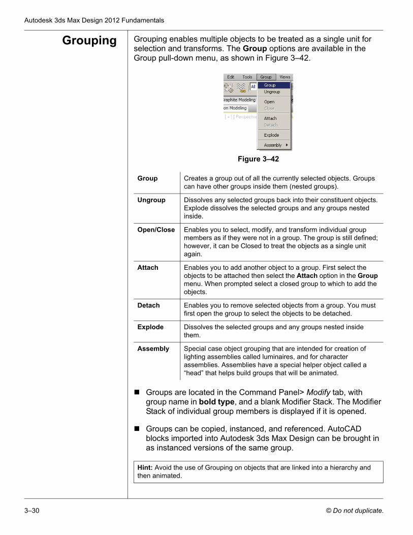
Grouping Grouping enables multiple objects to be treated as a single unit for selection and transforms. The Group options are available in the Group pull-down menu, as shown in Figure 3–42.
Figure 3–42
Groups are located in the Command Panel> Modify tab, with group name in bold type, and a blank Modifier Stack. The Modifier Stack of individual group members is displayed if it is opened.
Groups can be copied, instanced, and referenced. AutoCAD blocks imported into Autodesk 3ds Max Design can be brought in as instanced versions of the same group.
Group Creates a group out of all the currently selected objects. Groups can have other groups inside them (nested groups).
Ungroup Dissolves any selected groups back into their constituent objects. Explode dissolves the selected groups and any groups nested inside.
Open/Close Enables you to select, modify, and transform individual group members as if they were not in a group. The group is still defined; however, it can be Closed to treat the objects as a single unit again.
Attach Enables you to add another object to a group. First select the objects to be attached then select the Attach option in the Group menu. When prompted select a closed group to which to add the objects.
Detach Enables you to remove selected objects from a group. You must first open the group to select the objects to be detached.
Explode Dissolves the selected groups and any groups nested inside them.
Assembly Special case object grouping that are intended for creation of lighting assemblies called luminaires, and for character assemblies. Assemblies have a special helper object called a “head” that helps build groups that will be animated.
Hint: Avoid the use of Grouping on objects that are linked into a hierarchy and then animated.
Basic Modeling Techniques
© Do not duplicate. 3–31
Practice 3e Cloning and GroupingEstimated time for completion: 10 minutes.
In this practice you will complete the model of the light pole using Cloning and Groups.
1. Continue with the file MyLightPole06.max created in the previous practice. If you did not complete it, open Cloning and Grouping.max from your Class Files folder.
2. Click (Select by Name) or press <H> (shortcut key) to open the Select From Scene dialog box. In the dialog box, click
(Display Geometry) and select LP Fixture Housing, LP Globe, and LP Mounting Arm (hold down <Ctrl> to select
multiple items). Click to close the dialog box. All three items are now selected in the scene.
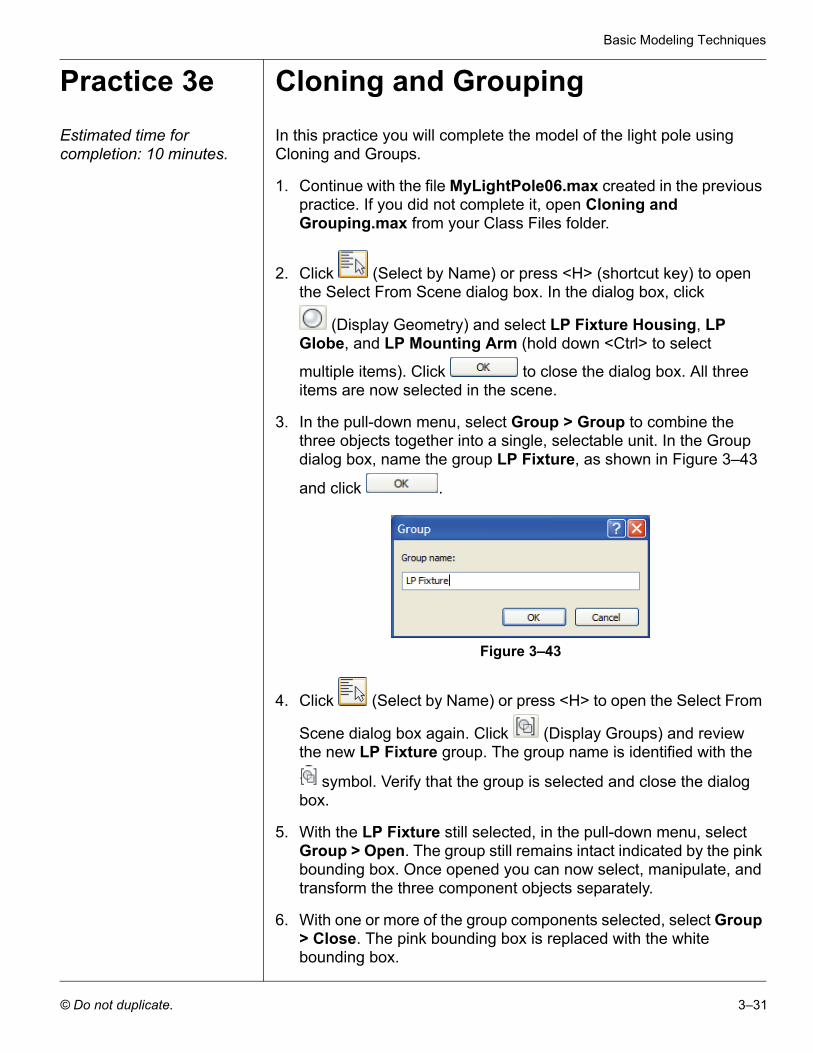
3. In the pull-down menu, select Group > Group to combine the three objects together into a single, selectable unit. In the Group dialog box, name the group LP Fixture, as shown in Figure 3–43
and click .
Figure 3–43
4. Click (Select by Name) or press <H> to open the Select From
Scene dialog box again. Click (Display Groups) and review the new LP Fixture group. The group name is identified with the
symbol. Verify that the group is selected and close the dialog box.
5. With the LP Fixture still selected, in the pull-down menu, select Group > Open. The group still remains intact indicated by the pink bounding box. Once opened you can now select, manipulate, and transform the three component objects separately.
6. With one or more of the group components selected, select Group > Close. The pink bounding box is replaced with the white bounding box.
Autodesk 3ds Max Design 2012 Fundamentals
3–32 © Do not duplicate.
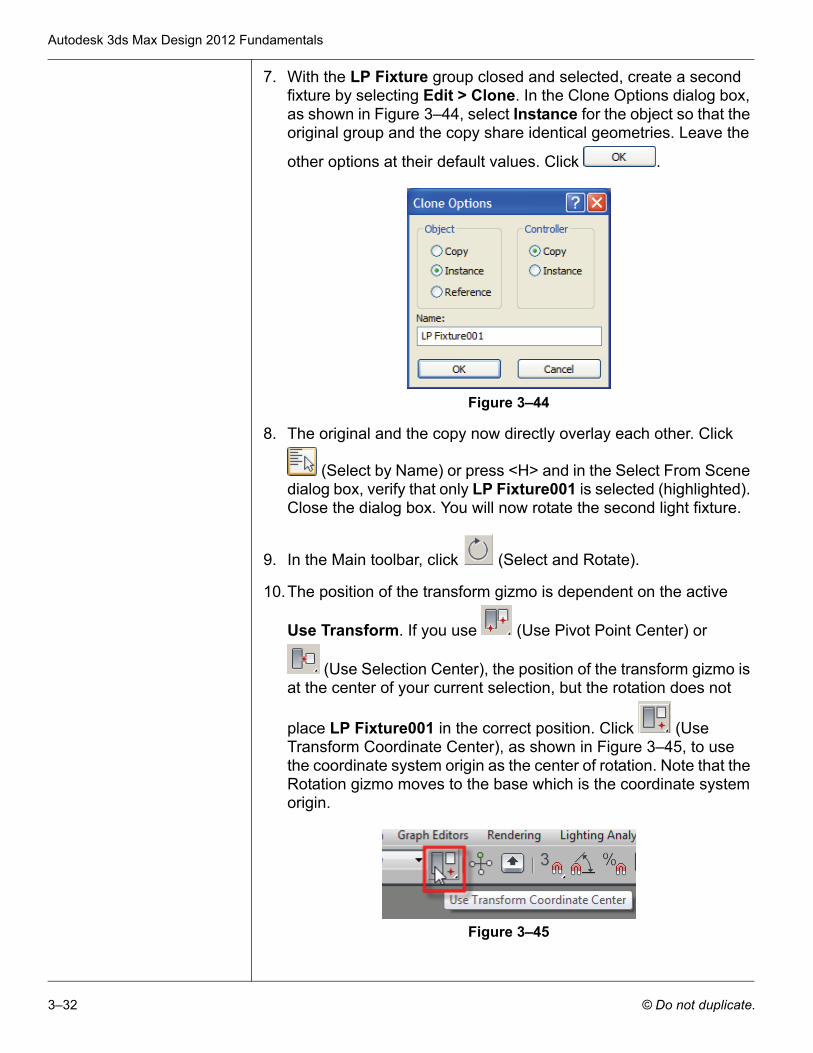
7. With the LP Fixture group closed and selected, create a second fixture by selecting Edit > Clone. In the Clone Options dialog box, as shown in Figure 3–44, select Instance for the object so that the original group and the copy share identical geometries. Leave the
other options at their default values. Click .
Figure 3–44
8. The original and the copy now directly overlay each other. Click
(Select by Name) or press <H> and in the Select From Scene dialog box, verify that only LP Fixture001 is selected (highlighted). Close the dialog box. You will now rotate the second light fixture.
9. In the Main toolbar, click (Select and Rotate).
10.The position of the transform gizmo is dependent on the active
Use Transform. If you use (Use Pivot Point Center) or
(Use Selection Center), the position of the transform gizmo is at the center of your current selection, but the rotation does not
place LP Fixture001 in the correct position. Click (Use Transform Coordinate Center), as shown in Figure 3–45, to use the coordinate system origin as the center of rotation. Note that the Rotation gizmo moves to the base which is the coordinate system origin.
Figure 3–45
Basic Modeling Techniques
© Do not duplicate. 3–33
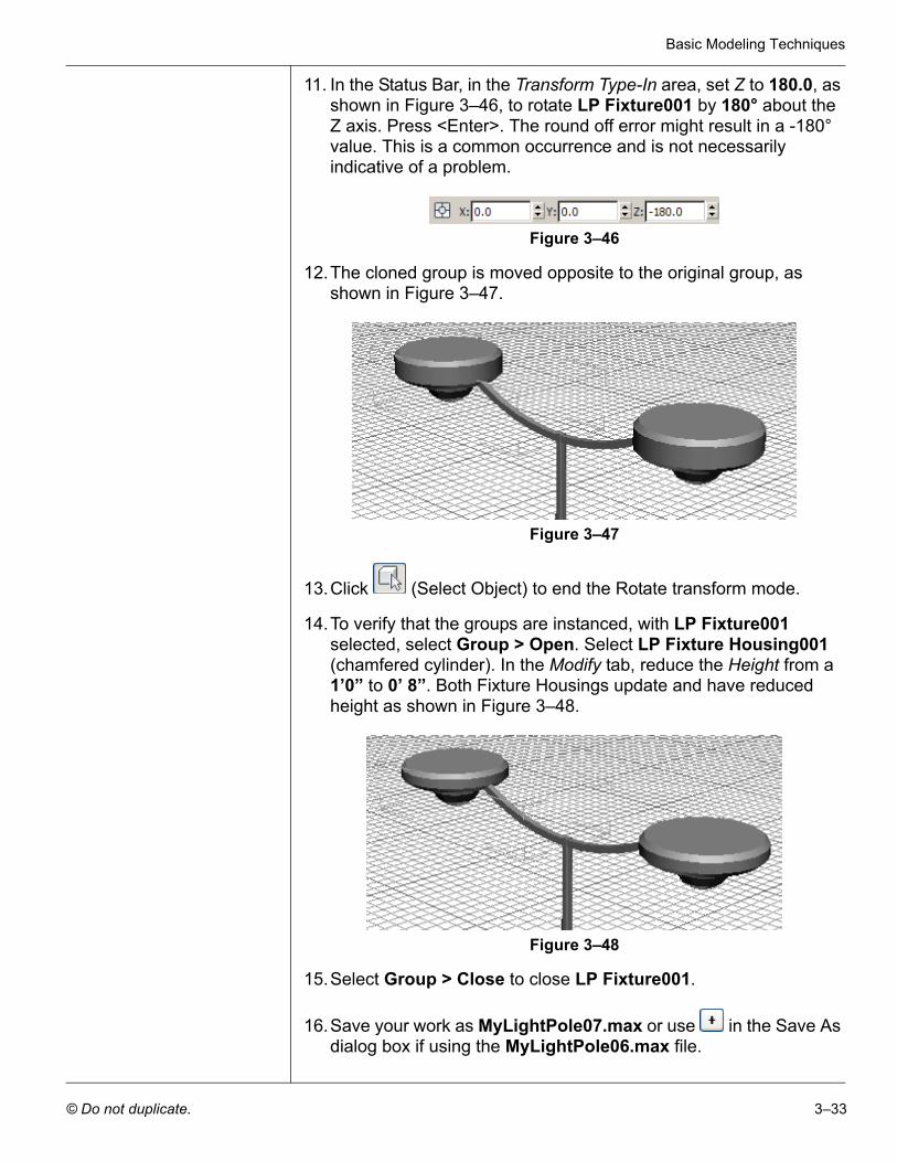
11. In the Status Bar, in the Transform Type-In area, set Z to 180.0, as shown in Figure 3–46, to rotate LP Fixture001 by 180° about the Z axis. Press <Enter>. The round off error might result in a -180° value. This is a common occurrence and is not necessarily indicative of a problem.
Figure 3–46
12.The cloned group is moved opposite to the original group, as shown in Figure 3–47.
Figure 3–47
13.Click (Select Object) to end the Rotate transform mode.
14.To verify that the groups are instanced, with LP Fixture001 selected, select Group > Open. Select LP Fixture Housing001 (chamfered cylinder). In the Modify tab, reduce the Height from a 1’0” to 0’ 8”. Both Fixture Housings update and have reduced height as shown in Figure 3–48.
Figure 3–48
15.Select Group > Close to close LP Fixture001.
16.Save your work as MyLightPole07.max or use in the Save As dialog box if using the MyLightPole06.max file.
Autodesk 3ds Max Design 2012 Fundamentals
3–34 © Do not duplicate.
3.6 Poly Modeling with Graphite Tools
Autodesk 3ds Max Design is a powerful environment for creating 3D models of virtually anything you can imagine. The “box modeling” technique is probably the most popular method of construction. It is also called polygon modeling or mesh modeling. Essentially it is the interactive creation of vertices, edges, faces, and surfaces in a free and artistic way. The term box modeling comes from the common practice of starting by building a box. The original components of the box are manipulated to create the entire model. You could as easily start with a plane, or any other 3D primitive, or a 2D Shape object.
Box modeling can be performed using either the Edit Mesh or Edit Poly modifiers, or be converted to an Editable Mesh or Editable Poly object. Any of these methods give you the access to the sub-object levels needed to do this type of modeling. The Edit Poly modifier is the most recent modeling technology added to Autodesk 3ds Max Design, so it should be the preferred choice in many cases. However, if you find unexpected results using Edit Poly, you can always convert the object to an editable mesh or editable poly object and discard the modifier. You can also use the Edit Mesh modifier which is the older technology and should be the most stable.
Basic Modeling Techniques
© Do not duplicate. 3–35
Practice 3f Box Modeling an ArmchairEstimated time for completion: 40 minutes.
In this practice you will learn some of the tools and techniques of box modeling using the Edit Poly modifier.
Task 1 - Model the Armchair.
1. Click > Reset to reset Autodesk 3ds Max Design.
2. In the Create tab ( ) > (Geometry), click in the Object Type rollout to activate the Box tool.
3. Click (Maximize Viewport) to display multiple viewports.
4. In the Perspective viewport, click and drag to define the length and width of the rectangle. Click and continue moving the mouse upwards to define the height.
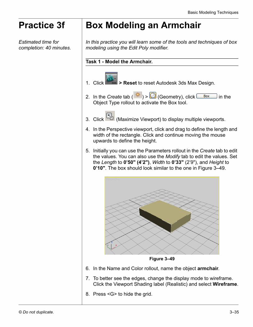
5. Initially you can use the Parameters rollout in the Create tab to edit the values. You can also use the Modify tab to edit the values. Set the Length to 0’50" (4’2"), Width to 0’33" (2’9"), and Height to 0’10". The box should look similar to the one in Figure 3–49.
Figure 3–49
6. In the Name and Color rollout, name the object armchair.
7. To better see the edges, change the display mode to wireframe. Click the Viewport Shading label (Realistic) and select Wireframe.
8. Press <G> to hide the grid.
Autodesk 3ds Max Design 2012 Fundamentals
3–36 © Do not duplicate.
9. If the Graphite Modeling Ribbon is only displaying tabs, click to display the commands in the panel.
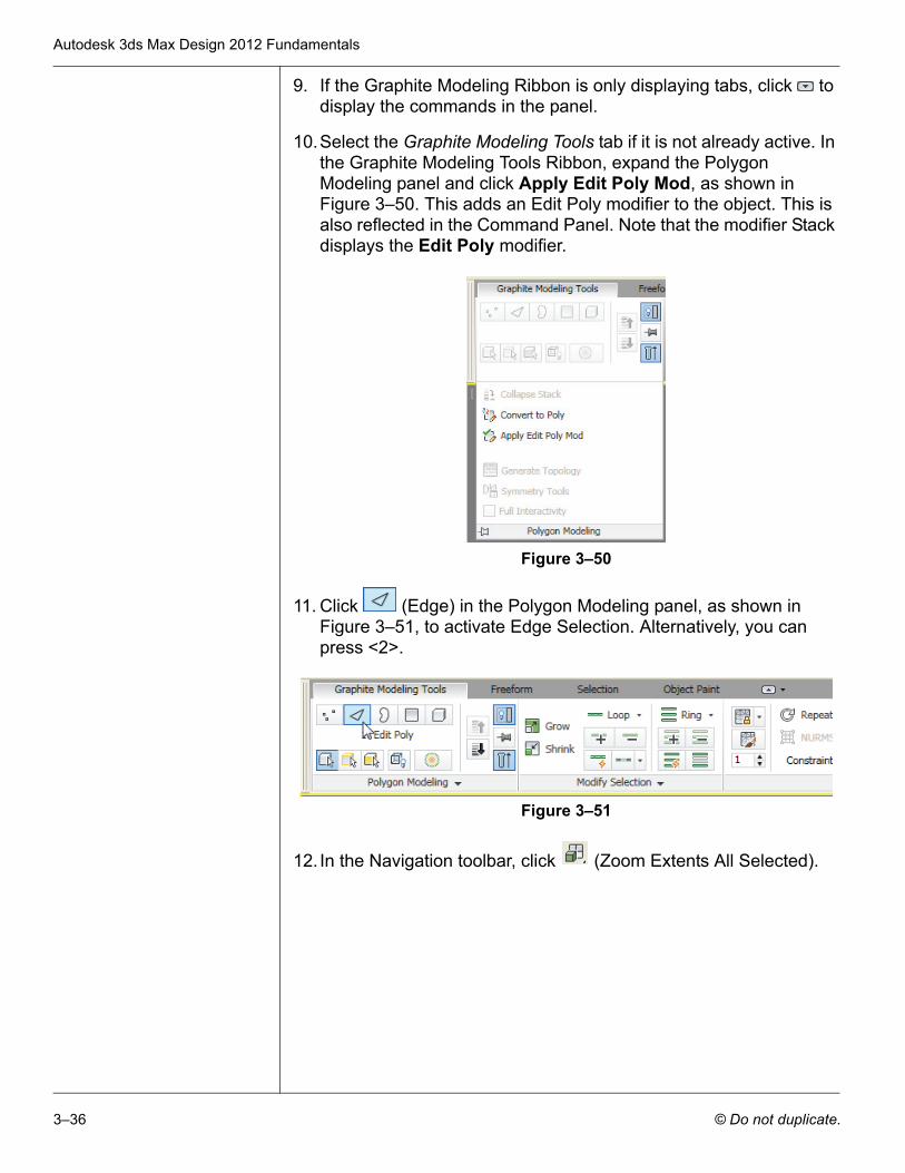
10.Select the Graphite Modeling Tools tab if it is not already active. In the Graphite Modeling Tools Ribbon, expand the Polygon Modeling panel and click Apply Edit Poly Mod, as shown in Figure 3–50. This adds an Edit Poly modifier to the object. This is also reflected in the Command Panel. Note that the modifier Stack displays the Edit Poly modifier.
Figure 3–50
11. Click (Edge) in the Polygon Modeling panel, as shown in Figure 3–51, to activate Edge Selection. Alternatively, you can press <2>.
Figure 3–51
12. In the Navigation toolbar, click (Zoom Extents All Selected).
Basic Modeling Techniques
© Do not duplicate. 3–37
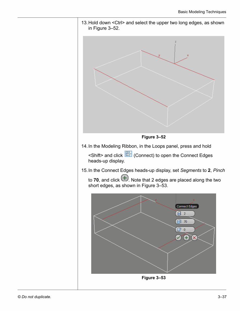
13.Hold down <Ctrl> and select the upper two long edges, as shown in Figure 3–52.
Figure 3–52
14. In the Modeling Ribbon, in the Loops panel, press and hold
<Shift> and click (Connect) to open the Connect Edges heads-up display.
15. In the Connect Edges heads-up display, set Segments to 2, Pinch
to 70, and click . Note that 2 edges are placed along the two short edges, as shown in Figure 3–53.
Figure 3–53
Autodesk 3ds Max Design 2012 Fundamentals
3–38 © Do not duplicate.
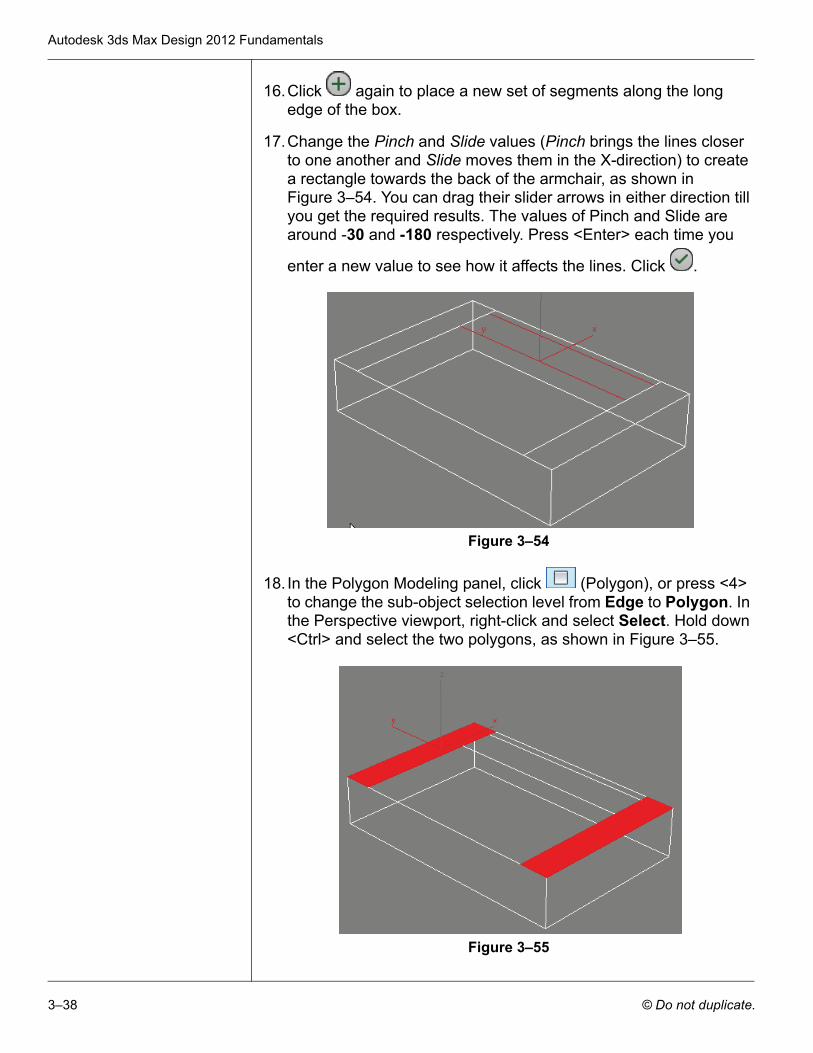
16.Click again to place a new set of segments along the long edge of the box.
17.Change the Pinch and Slide values (Pinch brings the lines closer to one another and Slide moves them in the X-direction) to create a rectangle towards the back of the armchair, as shown in Figure 3–54. You can drag their slider arrows in either direction till you get the required results. The values of Pinch and Slide are around -30 and -180 respectively. Press <Enter> each time you
enter a new value to see how it affects the lines. Click .
Figure 3–54
18. In the Polygon Modeling panel, click (Polygon), or press <4> to change the sub-object selection level from Edge to Polygon. In the Perspective viewport, right-click and select Select. Hold down <Ctrl> and select the two polygons, as shown in Figure 3–55.
Figure 3–55
Basic Modeling Techniques
© Do not duplicate. 3–39
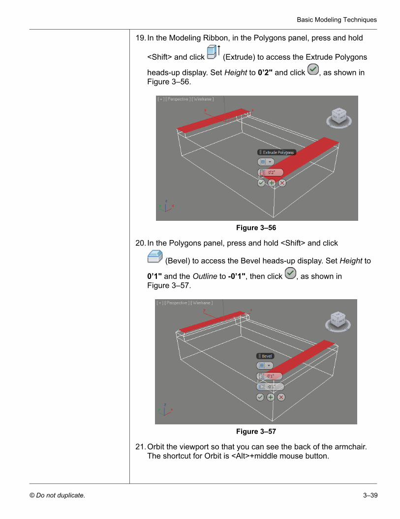
19. In the Modeling Ribbon, in the Polygons panel, press and hold
<Shift> and click (Extrude) to access the Extrude Polygons
heads-up display. Set Height to 0’2" and click , as shown in Figure 3–56.
Figure 3–56
20. In the Polygons panel, press and hold <Shift> and click
(Bevel) to access the Bevel heads-up display. Set Height to
0’1" and the Outline to -0’1", then click , as shown in Figure 3–57.
Figure 3–57
21.Orbit the viewport so that you can see the back of the armchair. The shortcut for Orbit is <Alt>+middle mouse button.
Autodesk 3ds Max Design 2012 Fundamentals
3–40 © Do not duplicate.
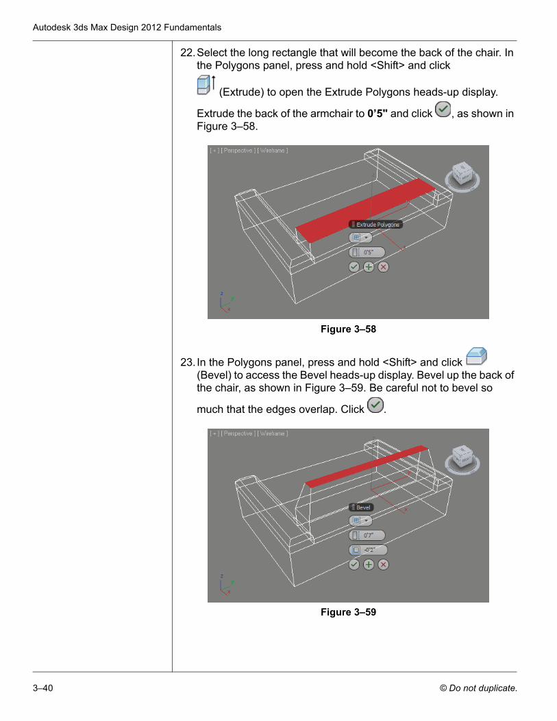
22.Select the long rectangle that will become the back of the chair. In the Polygons panel, press and hold <Shift> and click
(Extrude) to open the Extrude Polygons heads-up display.
Extrude the back of the armchair to 0’5" and click , as shown in Figure 3–58.
Figure 3–58
23. In the Polygons panel, press and hold <Shift> and click (Bevel) to access the Bevel heads-up display. Bevel up the back of the chair, as shown in Figure 3–59. Be careful not to bevel so
much that the edges overlap. Click .
Figure 3–59
Basic Modeling Techniques
© Do not duplicate. 3–41
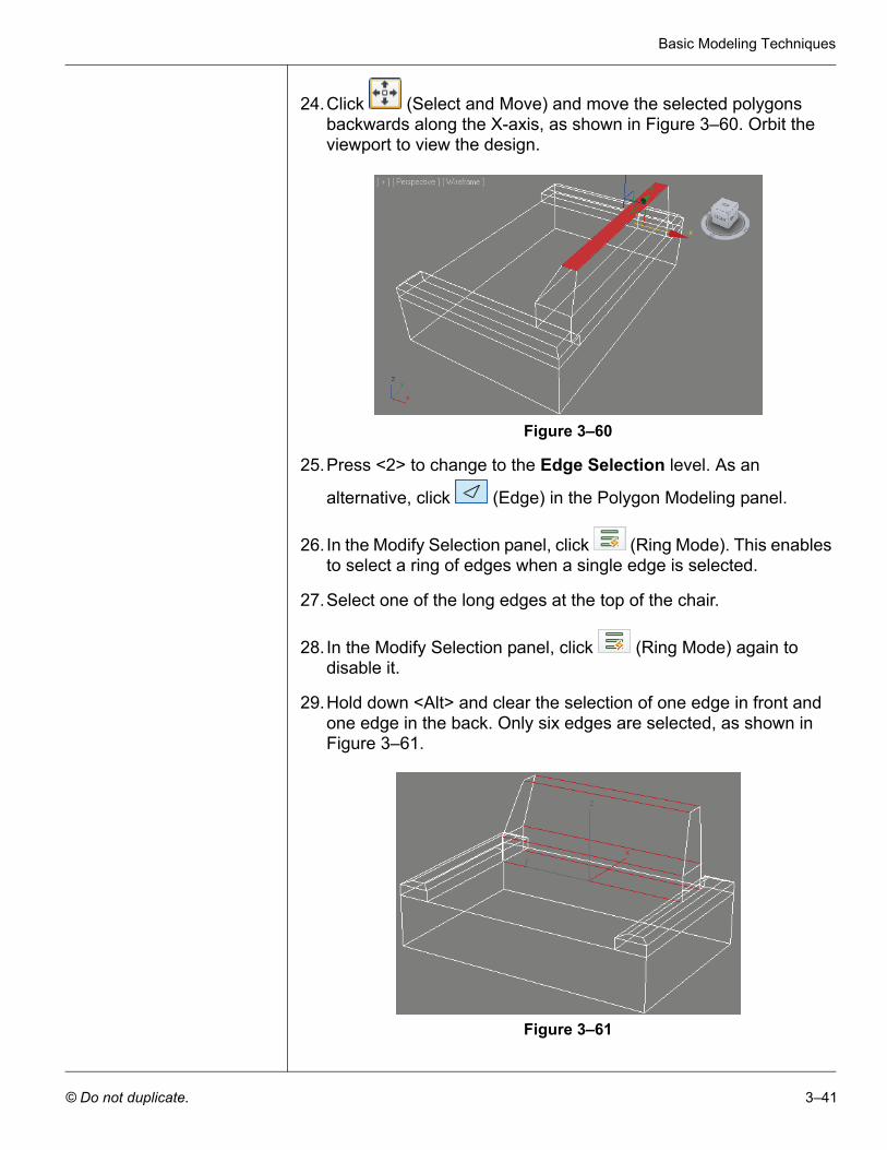
24.Click (Select and Move) and move the selected polygons backwards along the X-axis, as shown in Figure 3–60. Orbit the viewport to view the design.
Figure 3–60
25.Press <2> to change to the Edge Selection level. As an
alternative, click (Edge) in the Polygon Modeling panel.
26. In the Modify Selection panel, click (Ring Mode). This enables to select a ring of edges when a single edge is selected.
27.Select one of the long edges at the top of the chair.
28. In the Modify Selection panel, click (Ring Mode) again to disable it.
29.Hold down <Alt> and clear the selection of one edge in front and one edge in the back. Only six edges are selected, as shown in Figure 3–61.
Figure 3–61
Autodesk 3ds Max Design 2012 Fundamentals
3–42 © Do not duplicate.
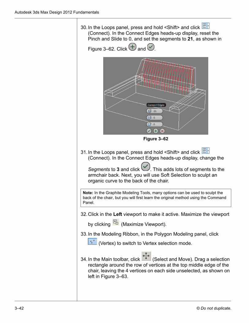
30. In the Loops panel, press and hold <Shift> and click (Connect). In the Connect Edges heads-up display, reset the Pinch and Slide to 0, and set the segments to 21, as shown in
Figure 3–62. Click and .
Figure 3–62
31. In the Loops panel, press and hold <Shift> and click (Connect). In the Connect Edges heads-up display, change the
Segments to 3 and click . This adds lots of segments to the armchair back. Next, you will use Soft Selection to sculpt an organic curve to the back of the chair.
32.Click in the Left viewport to make it active. Maximize the viewport
by clicking (Maximize Viewport).
33. In the Modeling Ribbon, in the Polygon Modeling panel, click
(Vertex) to switch to Vertex selection mode.
34. In the Main toolbar, click (Select and Move). Drag a selection rectangle around the row of vertices at the top middle edge of the chair, leaving the 4 vertices on each side unselected, as shown on left in Figure 3–63.
Note: In the Graphite Modeling Tools, many options can be used to sculpt the back of the chair, but you will first learn the original method using the Command Panel.
Basic Modeling Techniques
© Do not duplicate. 3–43
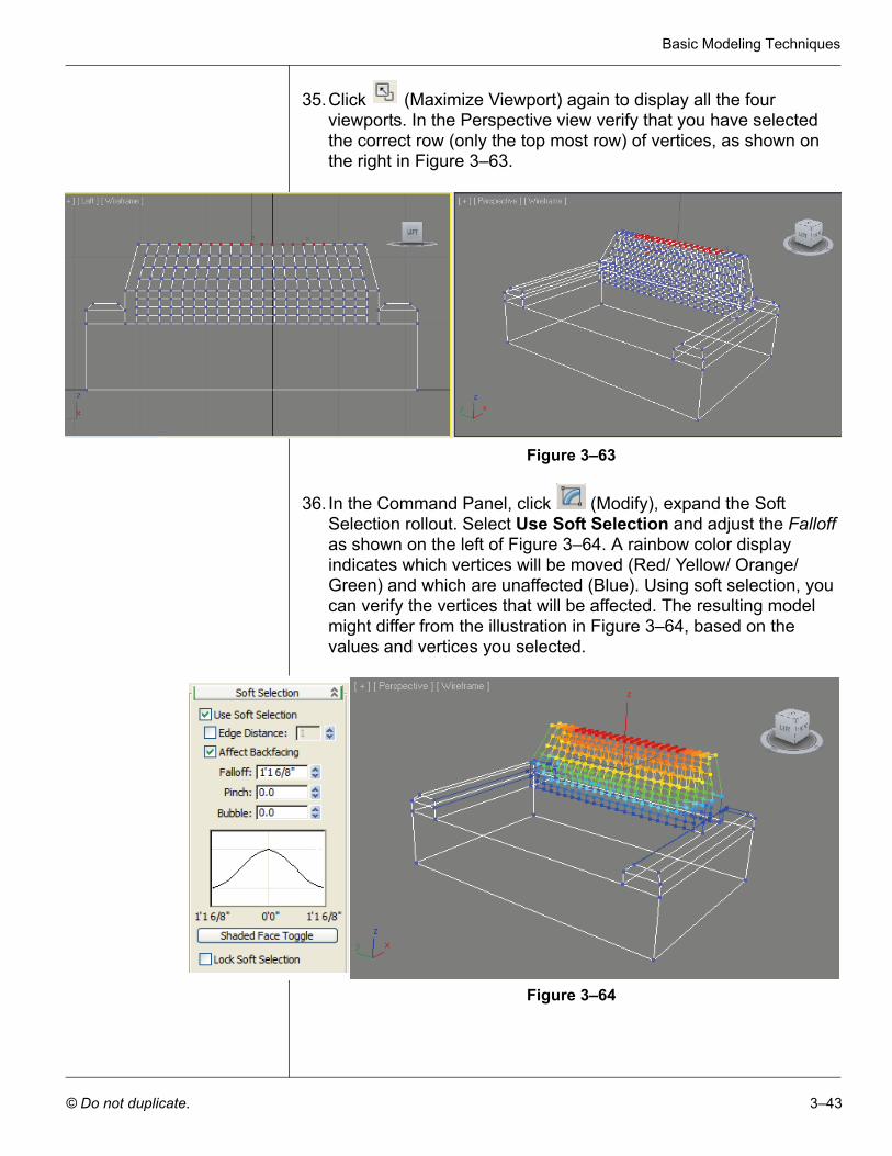
35.Click (Maximize Viewport) again to display all the four viewports. In the Perspective view verify that you have selected the correct row (only the top most row) of vertices, as shown on the right in Figure 3–63.
Figure 3–63
36. In the Command Panel, click (Modify), expand the Soft Selection rollout. Select Use Soft Selection and adjust the Falloff as shown on the left of Figure 3–64. A rainbow color display indicates which vertices will be moved (Red/ Yellow/ Orange/ Green) and which are unaffected (Blue). Using soft selection, you can verify the vertices that will be affected. The resulting model might differ from the illustration in Figure 3–64, based on the values and vertices you selected.
Figure 3–64
Autodesk 3ds Max Design 2012 Fundamentals
3–44 © Do not duplicate.
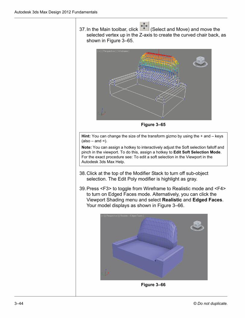
37. In the Main toolbar, click (Select and Move) and move the selected vertex up in the Z-axis to create the curved chair back, as shown in Figure 3–65.
Figure 3–65
38.Click at the top of the Modifier Stack to turn off sub-object selection. The Edit Poly modifier is highlight as gray.
39.Press <F3> to toggle from Wireframe to Realistic mode and <F4> to turn on Edged Faces mode. Alternatively, you can click the Viewport Shading menu and select Realistic and Edged Faces. Your model displays as shown in Figure 3–66.
Figure 3–66
Hint: You can change the size of the transform gizmo by using the + and – keys (also – and =).Note: You can assign a hotkey to interactively adjust the Soft selection falloff and pinch in the viewport. To do this, assign a hotkey to Edit Soft Selection Mode. For the exact procedure see: To edit a soft selection in the Viewport in the Autodesk 3ds Max Help.
Basic Modeling Techniques
© Do not duplicate. 3–45
40.Select Rendering > Environment to open the Environment and Effects dialog box. In the Background area, click on the Color swatch and select White (color) in the Color Selector dialog box.
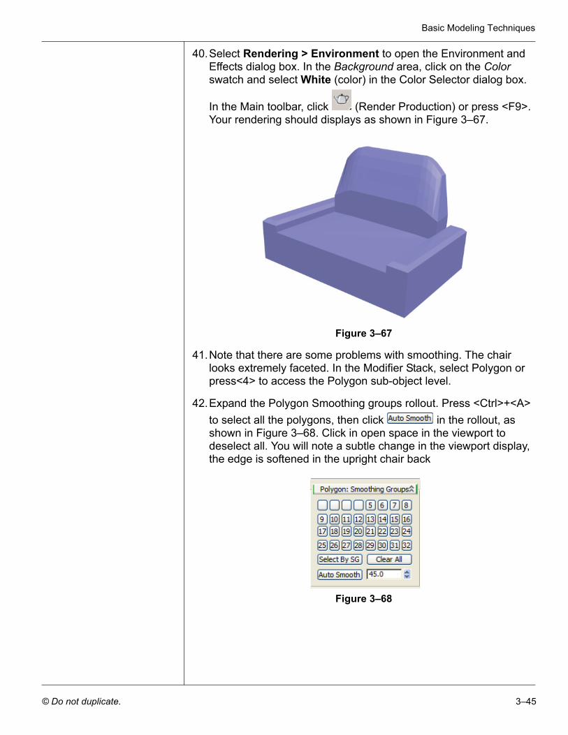
In the Main toolbar, click (Render Production) or press <F9>. Your rendering should displays as shown in Figure 3–67.
Figure 3–67
41.Note that there are some problems with smoothing. The chair looks extremely faceted. In the Modifier Stack, select Polygon or press<4> to access the Polygon sub-object level.
42.Expand the Polygon Smoothing groups rollout. Press <Ctrl>+<A> to select all the polygons, then click in the rollout, as shown in Figure 3–68. Click in open space in the viewport to deselect all. You will note a subtle change in the viewport display, the edge is softened in the upright chair back
Figure 3–68
Autodesk 3ds Max Design 2012 Fundamentals
3–46 © Do not duplicate.
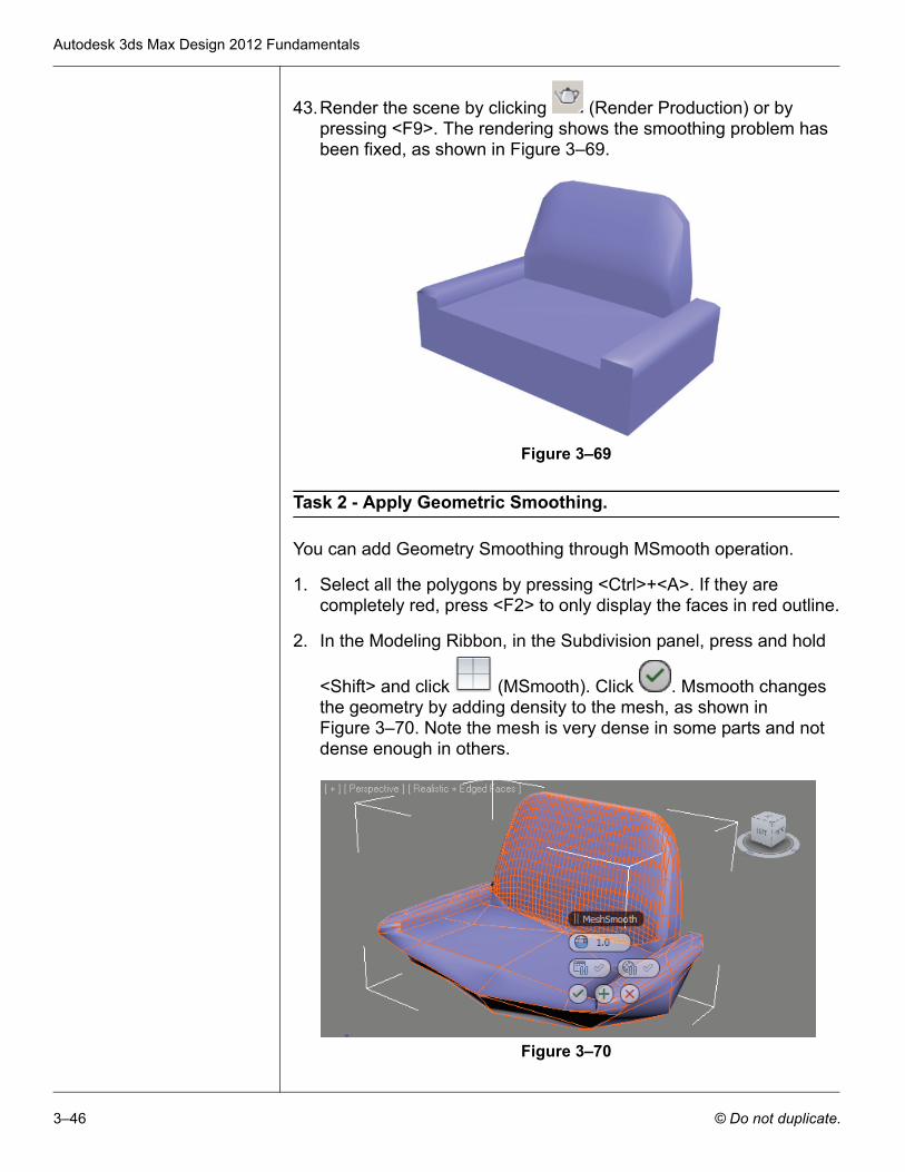
43.Render the scene by clicking (Render Production) or by pressing <F9>. The rendering shows the smoothing problem has been fixed, as shown in Figure 3–69.
Figure 3–69
Task 2 - Apply Geometric Smoothing.
You can add Geometry Smoothing through MSmooth operation.
1. Select all the polygons by pressing <Ctrl>+<A>. If they are completely red, press <F2> to only display the faces in red outline.
2. In the Modeling Ribbon, in the Subdivision panel, press and hold
<Shift> and click (MSmooth). Click . Msmooth changes the geometry by adding density to the mesh, as shown in Figure 3–70. Note the mesh is very dense in some parts and not dense enough in others.
Figure 3–70
Basic Modeling Techniques
© Do not duplicate. 3–47
Task 3 - Subdivide the Seat.
The back is dense, but the seat is not. You need to select all the polygons that need subdivision and then add a Subdivide modifier to them.
1. Verify that the Polygon level is still active and all the polygons are still selected. If not, press <Ctrl>+<A>. Also press <F2> to display the faces as completely red.
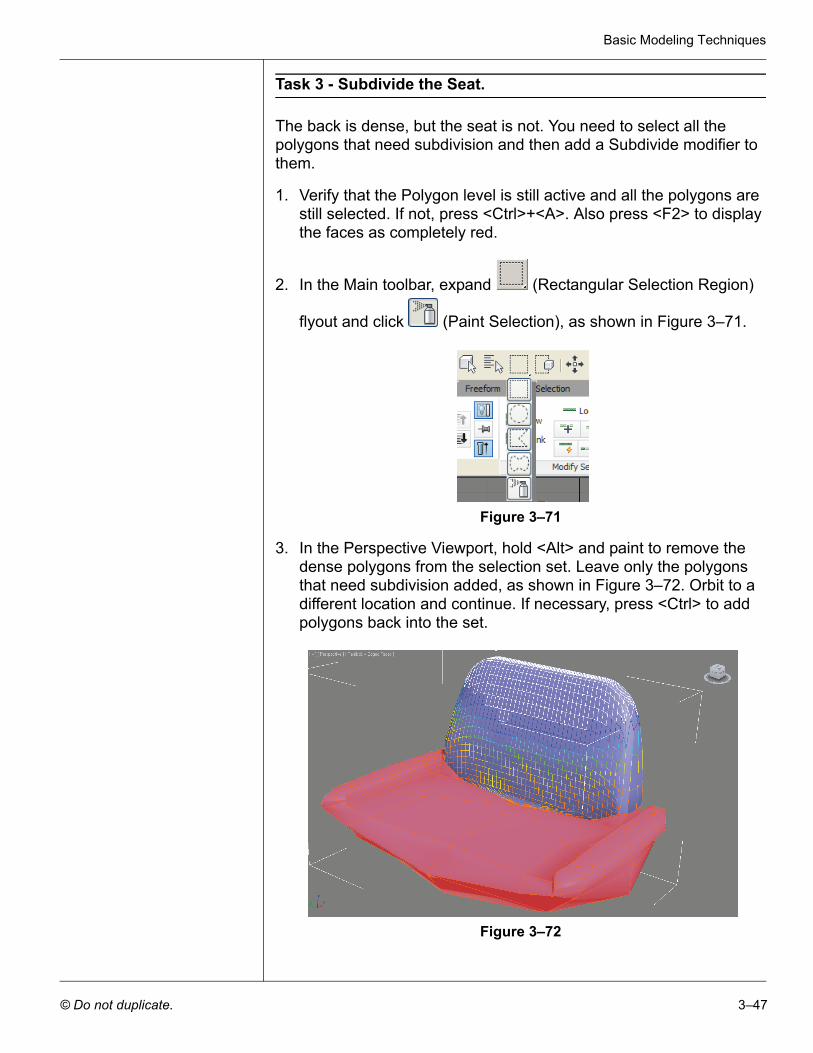
2. In the Main toolbar, expand (Rectangular Selection Region)
flyout and click (Paint Selection), as shown in Figure 3–71.
Figure 3–71
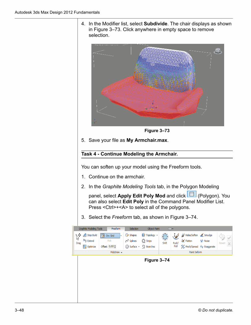
3. In the Perspective Viewport, hold <Alt> and paint to remove the dense polygons from the selection set. Leave only the polygons that need subdivision added, as shown in Figure 3–72. Orbit to a different location and continue. If necessary, press <Ctrl> to add polygons back into the set.
Figure 3–72
Autodesk 3ds Max Design 2012 Fundamentals
3–48 © Do not duplicate.
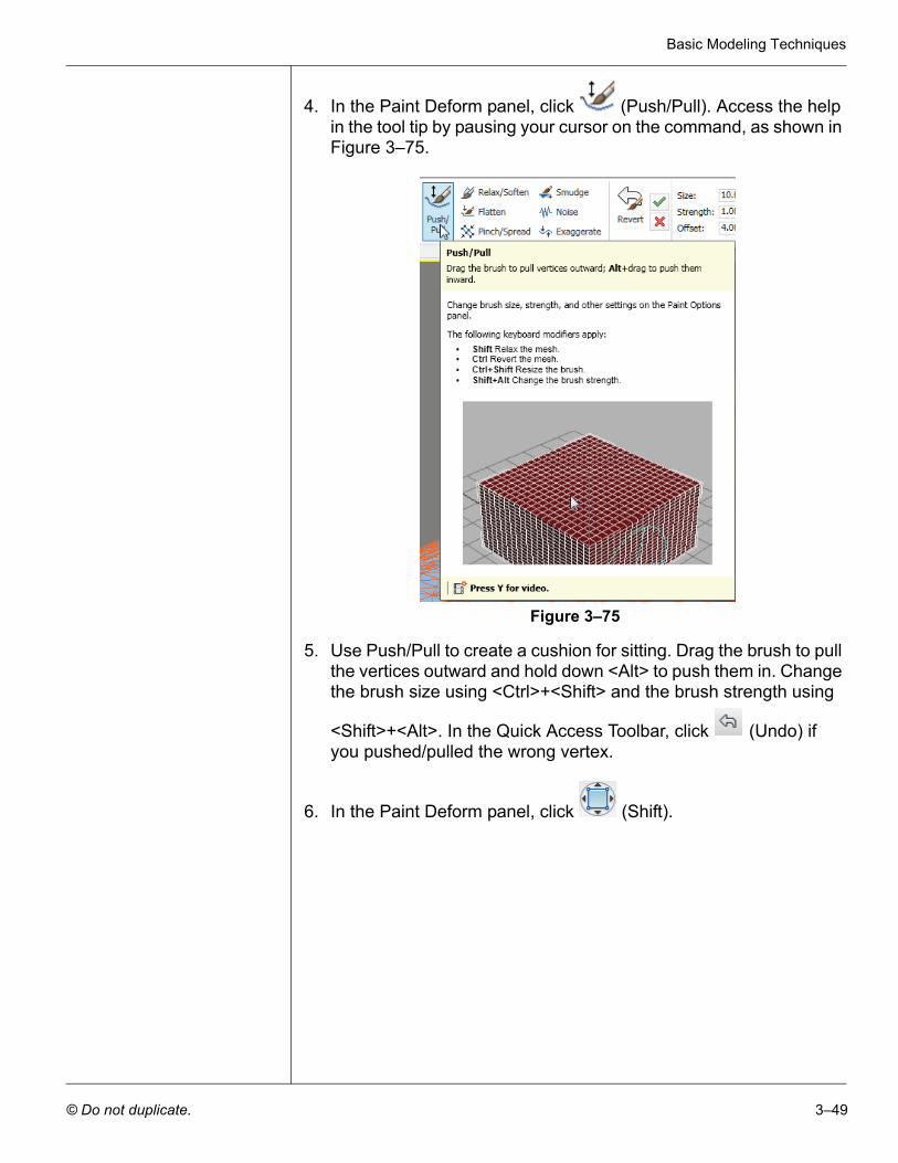
4. In the Modifier list, select Subdivide. The chair displays as shown in Figure 3–73. Click anywhere in empty space to remove selection.
Figure 3–73
5. Save your file as My Armchair.max.
Task 4 - Continue Modeling the Armchair.
You can soften up your model using the Freeform tools.
1. Continue on the armchair.
2. In the Graphite Modeling Tools tab, in the Polygon Modeling
panel, select Apply Edit Poly Mod and click (Polygon). You can also select Edit Poly in the Command Panel Modifier List. Press <Ctrl>+<A> to select all of the polygons.
3. Select the Freeform tab, as shown in Figure 3–74.
Figure 3–74
Basic Modeling Techniques
© Do not duplicate. 3–49
4. In the Paint Deform panel, click (Push/Pull). Access the help in the tool tip by pausing your cursor on the command, as shown in Figure 3–75.
Figure 3–75
5. Use Push/Pull to create a cushion for sitting. Drag the brush to pull the vertices outward and hold down <Alt> to push them in. Change the brush size using <Ctrl>+<Shift> and the brush strength using
<Shift>+<Alt>. In the Quick Access Toolbar, click (Undo) if you pushed/pulled the wrong vertex.
6. In the Paint Deform panel, click (Shift).
Autodesk 3ds Max Design 2012 Fundamentals
3–50 © Do not duplicate.
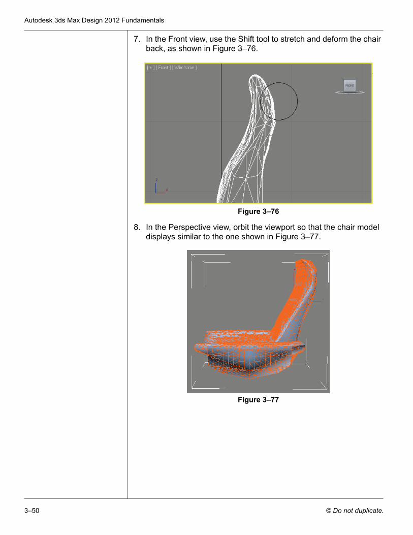
7. In the Front view, use the Shift tool to stretch and deform the chair back, as shown in Figure 3–76.
Figure 3–76
8. In the Perspective view, orbit the viewport so that the chair model displays similar to the one shown in Figure 3–77.
Figure 3–77
Basic Modeling Techniques
© Do not duplicate. 3–51
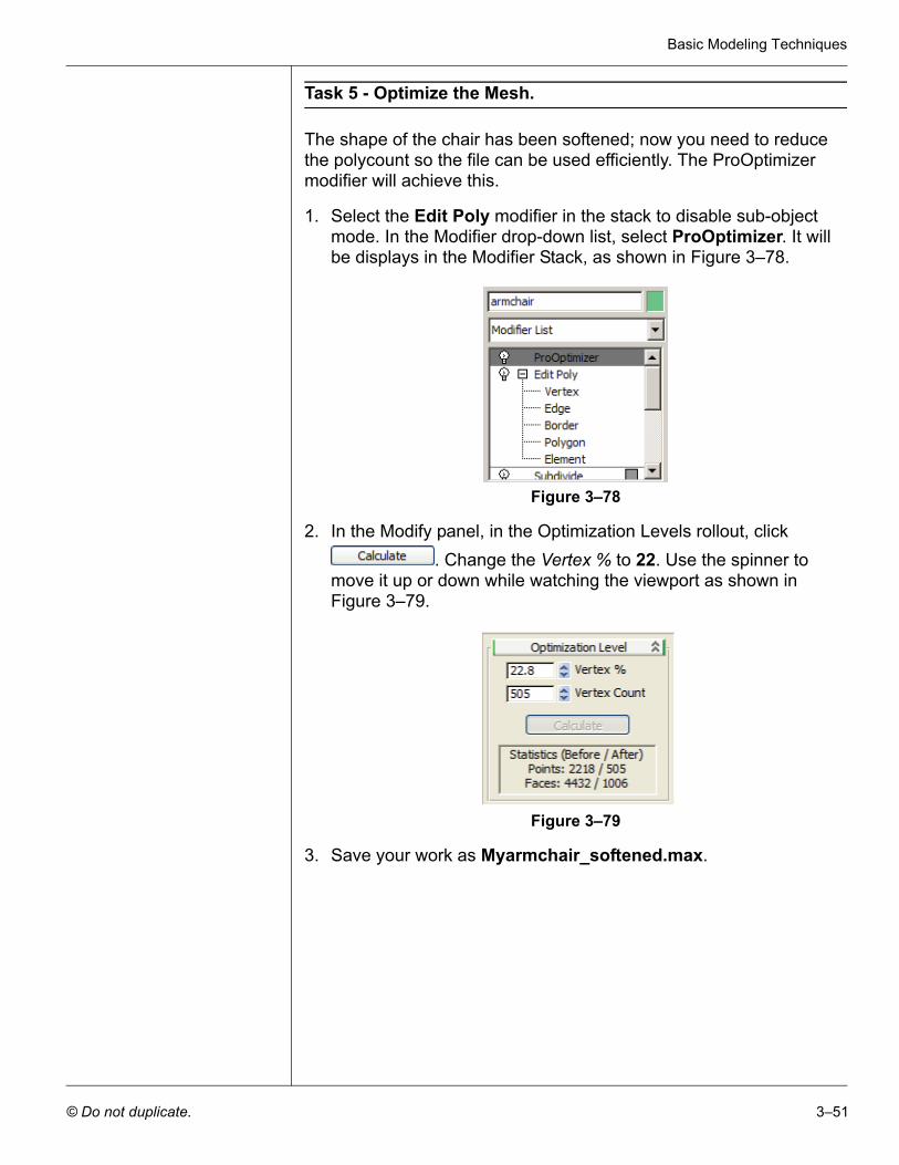
Task 5 - Optimize the Mesh.
The shape of the chair has been softened; now you need to reduce the polycount so the file can be used efficiently. The ProOptimizer modifier will achieve this.
1. Select the Edit Poly modifier in the stack to disable sub-object mode. In the Modifier drop-down list, select ProOptimizer. It will be displays in the Modifier Stack, as shown in Figure 3–78.
Figure 3–78
2. In the Modify panel, in the Optimization Levels rollout, click . Change the Vertex % to 22. Use the spinner to
move it up or down while watching the viewport as shown in Figure 3–79.
Figure 3–79
3. Save your work as Myarmchair_softened.max.
Autodesk 3ds Max Design 2012 Fundamentals
3–52 © Do not duplicate.
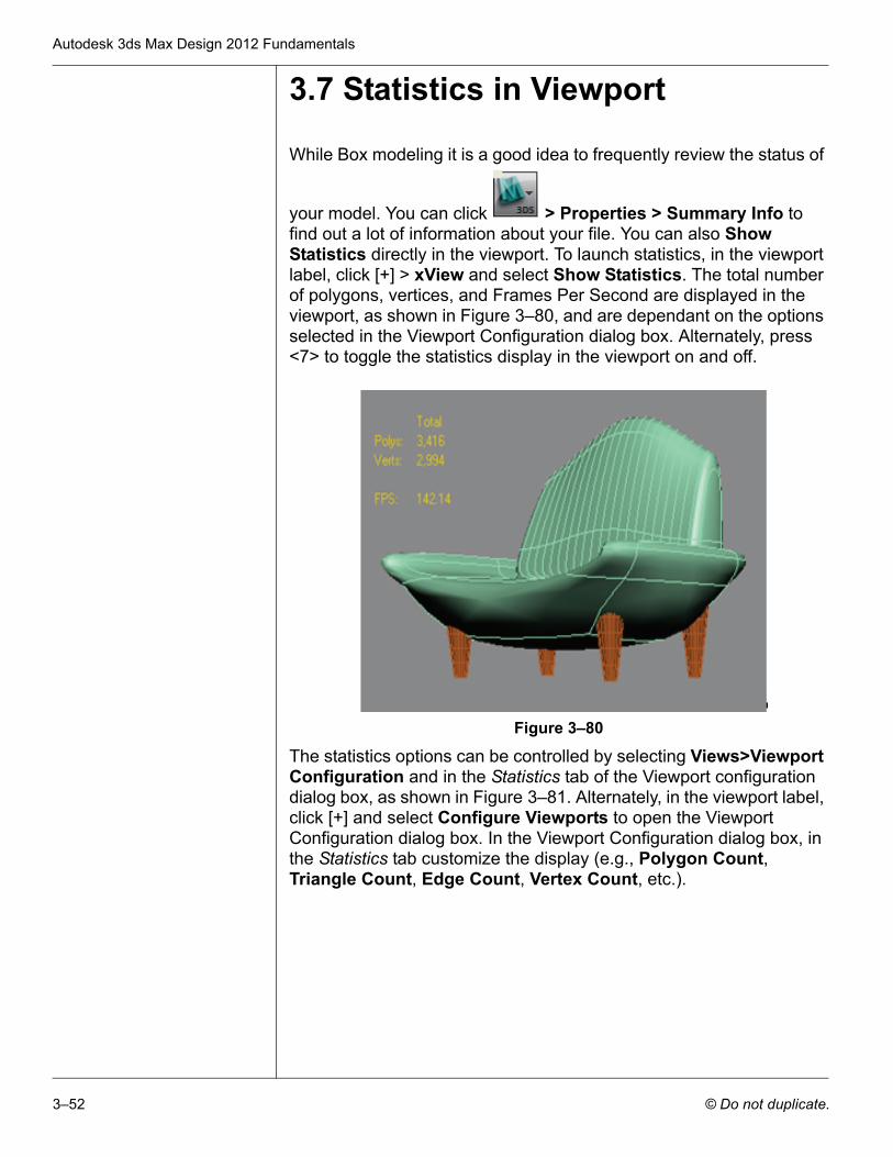
3.7 Statistics in Viewport
While Box modeling it is a good idea to frequently review the status of
your model. You can click > Properties > Summary Info to find out a lot of information about your file. You can also Show Statistics directly in the viewport. To launch statistics, in the viewport label, click [+] > xView and select Show Statistics. The total number of polygons, vertices, and Frames Per Second are displayed in the viewport, as shown in Figure 3–80, and are dependant on the options selected in the Viewport Configuration dialog box. Alternately, press <7> to toggle the statistics display in the viewport on and off.
Figure 3–80
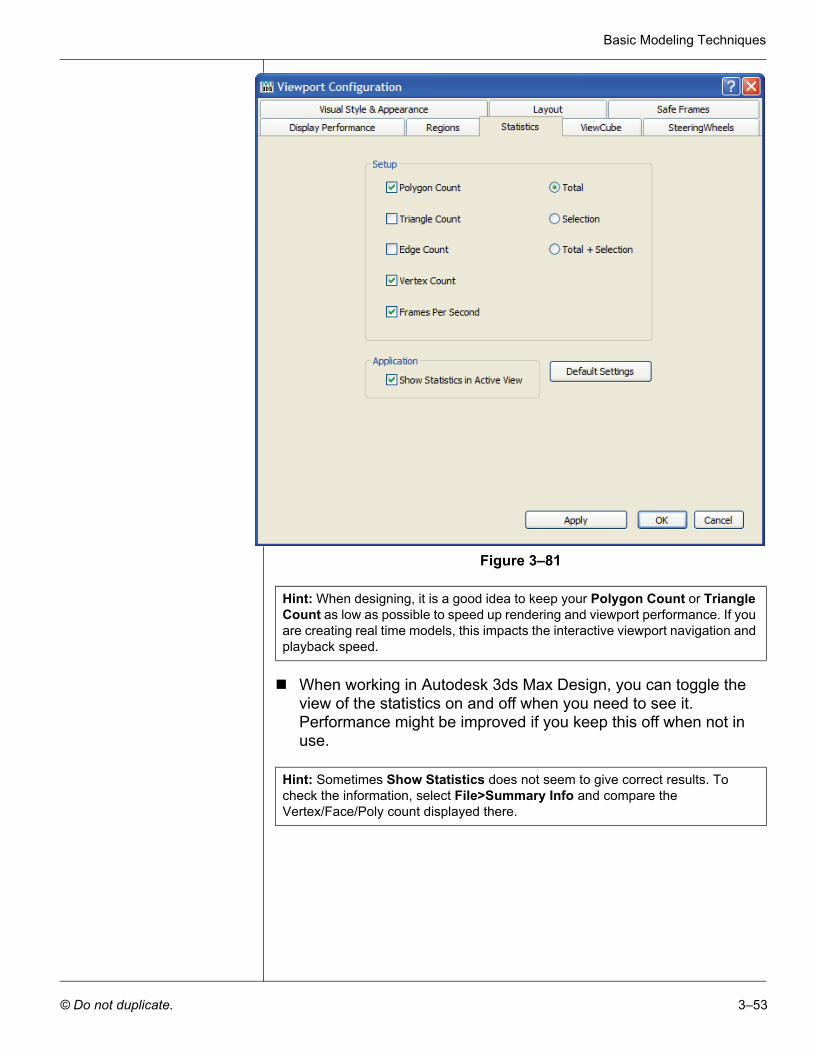
The statistics options can be controlled by selecting Views>Viewport Configuration and in the Statistics tab of the Viewport configuration dialog box, as shown in Figure 3–81. Alternately, in the viewport label, click [+] and select Configure Viewports to open the Viewport Configuration dialog box. In the Viewport Configuration dialog box, in the Statistics tab customize the display (e.g., Polygon Count, Triangle Count, Edge Count, Vertex Count, etc.).
Basic Modeling Techniques
© Do not duplicate. 3–53
Figure 3–81
When working in Autodesk 3ds Max Design, you can toggle the view of the statistics on and off when you need to see it. Performance might be improved if you keep this off when not in use.
Hint: When designing, it is a good idea to keep your Polygon Count or Triangle Count as low as possible to speed up rendering and viewport performance. If you are creating real time models, this impacts the interactive viewport navigation and playback speed.
Hint: Sometimes Show Statistics does not seem to give correct results. To check the information, select File>Summary Info and compare the Vertex/Face/Poly count displayed there.
Autodesk 3ds Max Design 2012 Fundamentals
3–54 © Do not duplicate.
Chapter Review Questions
1. Where can you change the parameters of an object after you have created it?
2. How do you display the transform (Move, Rotate, or Scale) gizmo if it is missing on the object in the viewport?
3. How do you access Sub-object modes to modify an object or a modifier of an object?
4. How are the X, Y, and Z axis measured in the Screen Coordinate system?
5. Which cloning option would you use when you want the changes made to the source object to affect the duplicate object, but when any changes are made to the duplicate, they do not affect the source object?