Embed Size (px)
Citation preview
Autodesk DirectConnect 2009 R2
Contents
Chapter 1 Autodesk DirectConnect 2009 R2 . . . . . . . . . . . . . . . . . 1
Chapter 2 What is Autodesk DirectConnect? . . . . . . . . . . . . . . . . . 3Supported products and translators . . . . . . . . . . . . . . . . . . . . 4
Chapter 3 What's new this release . . . . . . . . . . . . . . . . . . . . . . 15What's new . . . . . . . . . . . . . . . . . . . . . . . . . . . . . . . . 15Improvements . . . . . . . . . . . . . . . . . . . . . . . . . . . . . . . 16
Chapter 4 Find the latest information on the Web . . . . . . . . . . . . . 19
Chapter 5 Installing and Licensing . . . . . . . . . . . . . . . . . . . . . . 21Installing Autodesk DirectConnect . . . . . . . . . . . . . . . . . . . . 21Software deployment using group policies for Windows . . . . . . . . . 23Licensing Autodesk DirectConnect . . . . . . . . . . . . . . . . . . . . 27Importing Files . . . . . . . . . . . . . . . . . . . . . . . . . . . . . . 27
Chapter 6 Translator details . . . . . . . . . . . . . . . . . . . . . . . . . 29CATIA® V5 . . . . . . . . . . . . . . . . . . . . . . . . . . . . . . . . . 30CATIA® V4 . . . . . . . . . . . . . . . . . . . . . . . . . . . . . . . . . 33Autodesk Inventor® . . . . . . . . . . . . . . . . . . . . . . . . . . . 36
i
DWG DXF . . . . . . . . . . . . . . . . . . . . . . . . . . . . . . . . . 39IGES . . . . . . . . . . . . . . . . . . . . . . . . . . . . . . . . . . . . 41Open Inventor and Cosmo . . . . . . . . . . . . . . . . . . . . . . . . 46JT . . . . . . . . . . . . . . . . . . . . . . . . . . . . . . . . . . . . . . 48Pro/ENGINEER® . . . . . . . . . . . . . . . . . . . . . . . . . . . . . . 51SolidWorks® . . . . . . . . . . . . . . . . . . . . . . . . . . . . . . . . 54STEP . . . . . . . . . . . . . . . . . . . . . . . . . . . . . . . . . . . . 56STL . . . . . . . . . . . . . . . . . . . . . . . . . . . . . . . . . . . . . 58UGS NX . . . . . . . . . . . . . . . . . . . . . . . . . . . . . . . . . . 60
Chapter 7 Where to find imported data . . . . . . . . . . . . . . . . . . . 69For Autodesk AliasStudio . . . . . . . . . . . . . . . . . . . . . . . . . 69For Autodesk Maya 2009 . . . . . . . . . . . . . . . . . . . . . . . . . 70For Autodesk Showcase . . . . . . . . . . . . . . . . . . . . . . . . . . 70For Autodesk Opticore Realizer . . . . . . . . . . . . . . . . . . . . . . 71For Autodesk Opticore Studio . . . . . . . . . . . . . . . . . . . . . . . 72
Chapter 8 Glossary . . . . . . . . . . . . . . . . . . . . . . . . . . . . . . 73
Chapter 9 PCRE and BSD Licenses . . . . . . . . . . . . . . . . . . . . . . 75PCRE License . . . . . . . . . . . . . . . . . . . . . . . . . . . . . . . 75The BSD (Berkeley Software Distribution) license . . . . . . . . . . . . 76
Chapter 10 Legal Notice . . . . . . . . . . . . . . . . . . . . . . . . . . . . 77Trademarks . . . . . . . . . . . . . . . . . . . . . . . . . . . . . . . . 77
Index . . . . . . . . . . . . . . . . . . . . . . . . . . . . . . . . 79
ii | Contents
Autodesk DirectConnect2009 R2
What's new this release (page15)
Autodesk Inventor® (page36)CATIA® V4 (page 33)CATIA® V5 (page 30)
Open Inventor and Cosmo(page 46)
IGES (page 41)DWG DXF (page 39)
1
1
JT (page 48) SolidWorks® (page 54)Pro/ENGINEER® (page 51)
UGS NX (page 60)STL (page 58)STEP (page 56)
2 | Chapter 1 Autodesk DirectConnect 2009 R2
What is AutodeskDirectConnect?
Autodesk® DirectConnect’s a family of data translators that lets you import CAD data into:
■ Autodesk® AliasStudio™
■ Autodesk® Maya®
■ Autodesk® Showcase™
■ Autodesk® Opticore Realizer
■ Autodesk® Opticore Studio
Each Autodesk DirectConnect translator lets you import a specific CAD file format into oneor more of the Autodesk software products listed above. In addition, you can export someCAD file formats from some products with Autodesk® DirectConnect.
2
3
Supported products and translatorsClick any of the following Autodesk products to find:
■ File formats currently supported for import by Autodesk DirectConnect
■ The Autodesk products and bit versions that support them at the time ofthis release
■ Which file formats require additional Autodesk DirectConnect licenses onwhich products
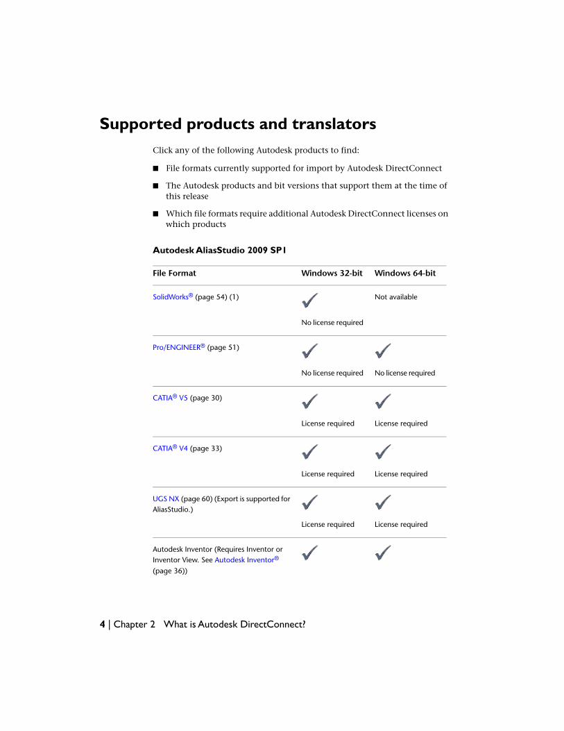
Autodesk AliasStudio 2009 SP1
Windows 64-bitWindows 32-bitFile Format
Not availableSolidWorks® (page 54) (1)
No license required
Pro/ENGINEER® (page 51)
No license requiredNo license required
CATIA® V5 (page 30)
License requiredLicense required
CATIA® V4 (page 33)
License requiredLicense required
UGS NX (page 60) (Export is supported forAliasStudio.)
License requiredLicense required
Autodesk Inventor (Requires Inventor orInventor View. See Autodesk Inventor®
(page 36))
4 | Chapter 2 What is Autodesk DirectConnect?
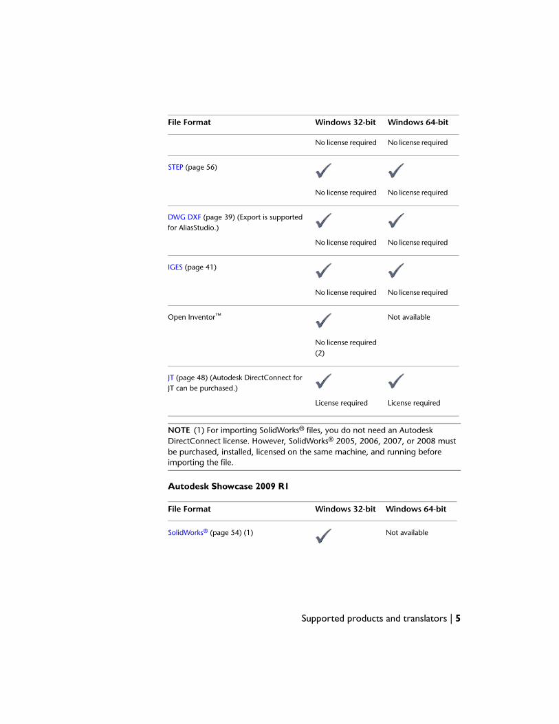
Windows 64-bitWindows 32-bitFile Format
No license requiredNo license required
STEP (page 56)
No license requiredNo license required
DWG DXF (page 39) (Export is supportedfor AliasStudio.)
No license requiredNo license required
IGES (page 41)
No license requiredNo license required
Not availableOpen Inventor™
No license required(2)
JT (page 48) (Autodesk DirectConnect forJT can be purchased.)
License requiredLicense required
NOTE (1) For importing SolidWorks® files, you do not need an AutodeskDirectConnect license. However, SolidWorks® 2005, 2006, 2007, or 2008 mustbe purchased, installed, licensed on the same machine, and running beforeimporting the file.
Autodesk Showcase 2009 R1
Windows 64-bitWindows 32-bitFile Format
Not availableSolidWorks® (page 54) (1)
Supported products and translators | 5
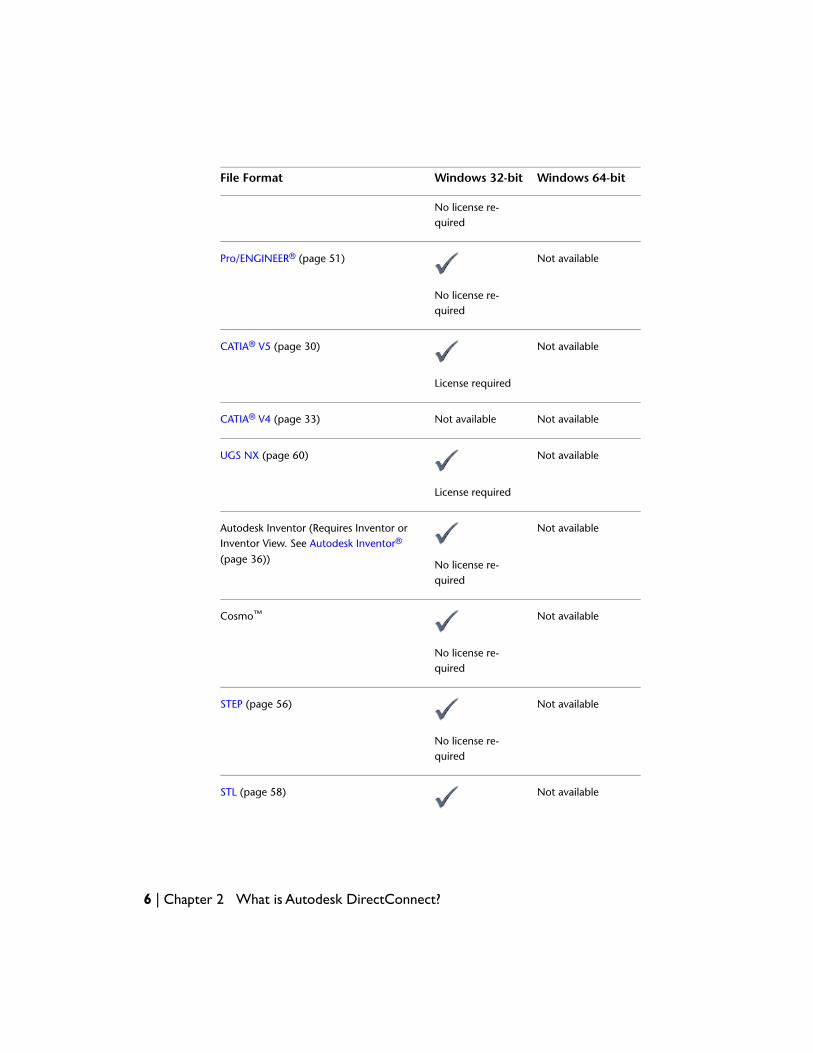
Windows 64-bitWindows 32-bitFile Format
No license re-quired
Not availablePro/ENGINEER® (page 51)
No license re-quired
Not availableCATIA® V5 (page 30)
License required
Not availableNot availableCATIA® V4 (page 33)
Not availableUGS NX (page 60)
License required
Not availableAutodesk Inventor (Requires Inventor orInventor View. See Autodesk Inventor®
(page 36)) No license re-quired
Not availableCosmo™
No license re-quired
Not availableSTEP (page 56)
No license re-quired
Not availableSTL (page 58)
6 | Chapter 2 What is Autodesk DirectConnect?
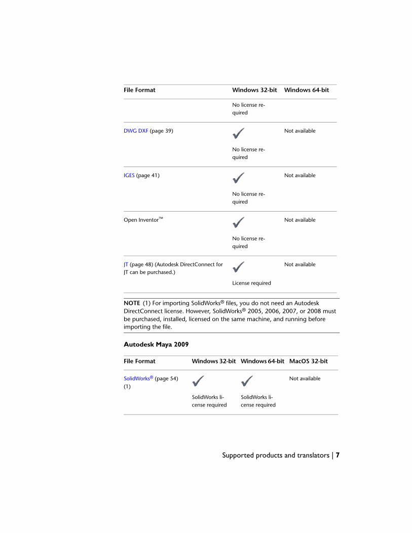
Windows 64-bitWindows 32-bitFile Format
No license re-quired
Not availableDWG DXF (page 39)
No license re-quired
Not availableIGES (page 41)
No license re-quired
Not availableOpen Inventor™
No license re-quired
Not availableJT (page 48) (Autodesk DirectConnect forJT can be purchased.)
License required
NOTE (1) For importing SolidWorks® files, you do not need an AutodeskDirectConnect license. However, SolidWorks® 2005, 2006, 2007, or 2008 mustbe purchased, installed, licensed on the same machine, and running beforeimporting the file.
Autodesk Maya 2009
MacOS 32-bitWindows 64-bitWindows 32-bitFile Format
Not availableSolidWorks® (page 54)(1)
SolidWorks li-cense required
SolidWorks li-cense required
Supported products and translators | 7
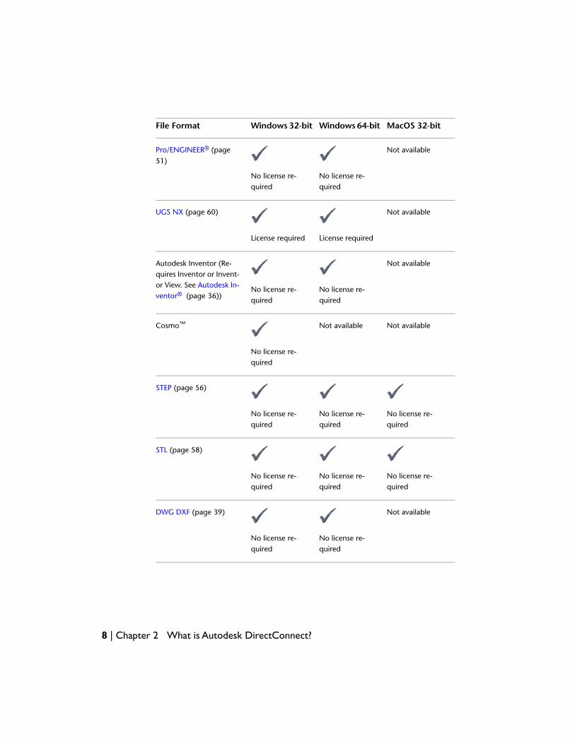
MacOS 32-bitWindows 64-bitWindows 32-bitFile Format
Not availablePro/ENGINEER® (page51)
No license re-quired
No license re-quired
Not availableUGS NX (page 60)
License requiredLicense required
Not availableAutodesk Inventor (Re-quires Inventor or Invent-or View. See Autodesk In-ventor® (page 36))
No license re-quired
No license re-quired
Not availableNot availableCosmo™
No license re-quired
STEP (page 56)
No license re-quired
No license re-quired
No license re-quired
STL (page 58)
No license re-quired
No license re-quired
No license re-quired
Not availableDWG DXF (page 39)
No license re-quired
No license re-quired
8 | Chapter 2 What is Autodesk DirectConnect?
MacOS 32-bitWindows 64-bitWindows 32-bitFile Format
IGES (page 41)
No license re-quired
No license re-quired
No license re-quired
Not availableNot availableOpen Inventor™
No license re-quired
Not availableNot availableNot availableJT (page 48)
NOTE (1) For importing SolidWorks® files, you do not need an AutodeskDirectConnect license. However, SolidWorks® 2005, 2006, 2007, or 2008 mustbe purchased, installed, licensed on the same machine, and running beforeimporting the file.
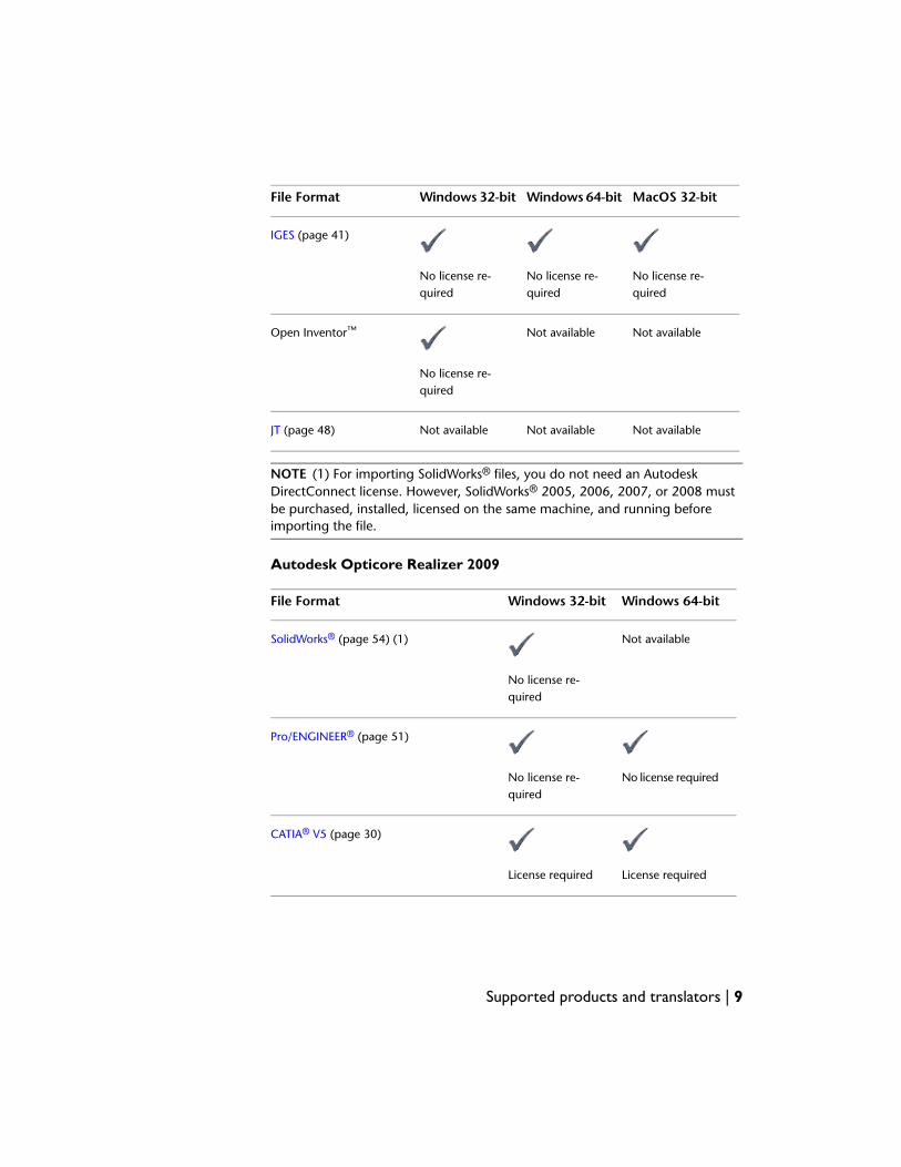
Autodesk Opticore Realizer 2009
Windows 64-bitWindows 32-bitFile Format
Not availableSolidWorks® (page 54) (1)
No license re-quired
Pro/ENGINEER® (page 51)
No license requiredNo license re-quired
CATIA® V5 (page 30)
License requiredLicense required
Supported products and translators | 9
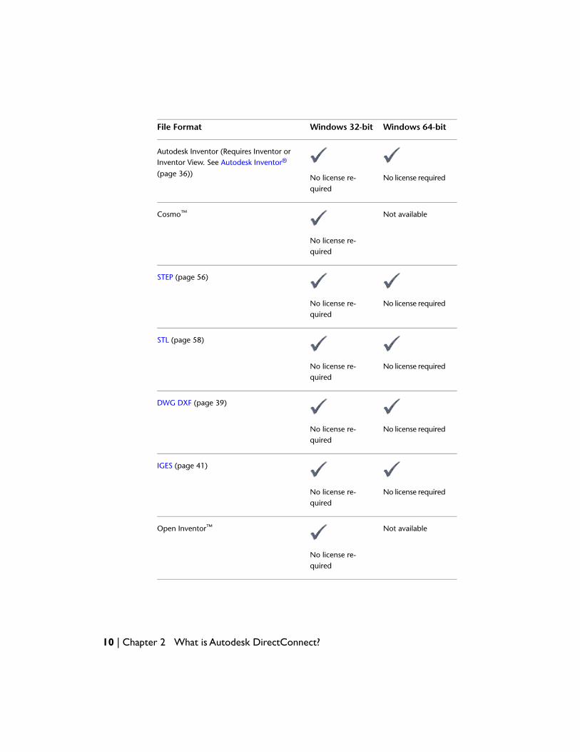
Windows 64-bitWindows 32-bitFile Format
Autodesk Inventor (Requires Inventor orInventor View. See Autodesk Inventor®
(page 36)) No license requiredNo license re-quired
Not availableCosmo™
No license re-quired
STEP (page 56)
No license requiredNo license re-quired
STL (page 58)
No license requiredNo license re-quired
DWG DXF (page 39)
No license requiredNo license re-quired
IGES (page 41)
No license requiredNo license re-quired
Not availableOpen Inventor™
No license re-quired
10 | Chapter 2 What is Autodesk DirectConnect?
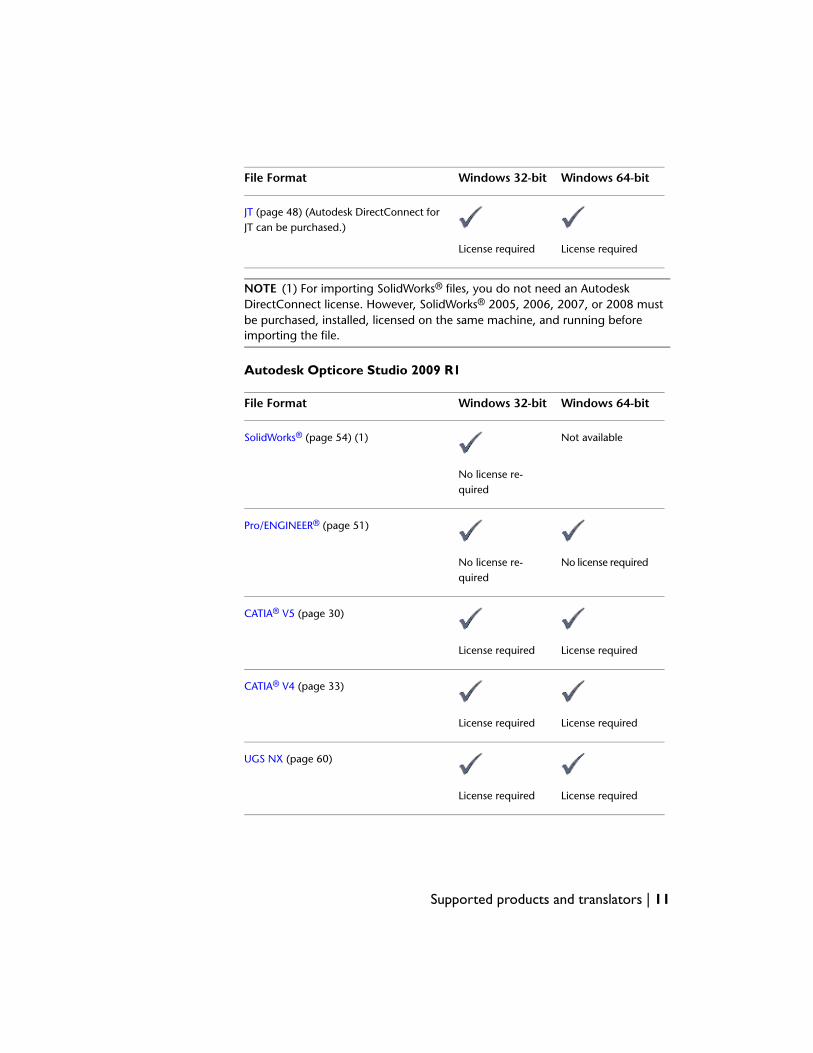
Windows 64-bitWindows 32-bitFile Format
JT (page 48) (Autodesk DirectConnect forJT can be purchased.)
License requiredLicense required
NOTE (1) For importing SolidWorks® files, you do not need an AutodeskDirectConnect license. However, SolidWorks® 2005, 2006, 2007, or 2008 mustbe purchased, installed, licensed on the same machine, and running beforeimporting the file.
Autodesk Opticore Studio 2009 R1
Windows 64-bitWindows 32-bitFile Format
Not availableSolidWorks® (page 54) (1)
No license re-quired
Pro/ENGINEER® (page 51)
No license requiredNo license re-quired
CATIA® V5 (page 30)
License requiredLicense required
CATIA® V4 (page 33)
License requiredLicense required
UGS NX (page 60)
License requiredLicense required
Supported products and translators | 11

Windows 64-bitWindows 32-bitFile Format
Autodesk Inventor (Requires Inventor orInventor View. See Autodesk Inventor®
(page 36)) No license requiredNo license re-quired
Not availableCosmo™
No license re-quired
STEP (page 56)
No license requiredNo license re-quired
STL (page 58)
No license requiredNo license re-quired
DWG DXF (page 39)
No license requiredNo license re-quired
IGES (page 41)
No license requiredNo license re-quired
Not availableOpen Inventor™
No license re-quired
12 | Chapter 2 What is Autodesk DirectConnect?

Windows 64-bitWindows 32-bitFile Format
JT (page 48) (Autodesk DirectConnect forJT can be purchased.)
License requiredLicense required
NOTE (1) For importing SolidWorks® files, you do not need an AutodeskDirectConnect license. However, SolidWorks® 2005, 2006, 2007, or 2008 mustbe purchased, installed, licensed on the same machine, and running beforeimporting the file.
Supported products and translators | 13

14
What's new this release
This section outlines enhancements for the DirectConnect 2009 R2 version (released 2008),in addition to various bug fixes.
What's newThe following improvements and enhancements have been made to AutodeskDirectConnect:
■ CATIA V4 import for AliasStudio 2009 SP1, Showcase 2009 R1, and OpticoreStudio 2009 R1.
■ Autodesk Inventor and Pro/Engineer import for Maya 2009 R1.
■ Group policy installation alignment.
■ UGNX import for Opticore Studio 2009 R1.
3
15
NOTE For licensing information, please see Supported products and translators(page 4).
ImprovementsCATIA V4
■ CATIA V4 data can now be imported into AliasStudio and converted to anAlias wire file.
CATIA V5
■ CATIA V5 Volume data can be imported into AliasStudio, even with Importby Layers on.
■ CATIA V5 data can now be imported into AliasStudio and converted toAlias wire files without causing tessellation problems.
■ The processing time for importing large CATIA V5 files in Showcase hasbeen greatly reduced.
UG and UGNX
■ UG assembly files containing trimmed curves with a hyperbola as its basiscurve can be imported.
■ Surfaces from imported data from UG are now interpreted correctly.
■ UG files with trim surfaces import correctly.
■ Trimming issues with UGNX have been fixed.
■ Parasolid trimmed filleted and planar data in UGNX are now trimmedcorrectly.
■ Parasolid data for UGNX is now interpreted correctly.
■ UGNX3 and UGNX4 files are imported properly into AliasStudio 2009.
■ The installation process has changed to make it faster and easier to get upand running.
■ Translation of CATIA V5 entities, such as fillet, chamfer, offsets, sweptsurface, and other procedurally-defined surfaces, has been improved.
16 | Chapter 3 What's new this release

■ For DWG files, you can now export different versions of the file , such as2007, 2004, 2000, or R14. For DXF, you can export 2007, 2004, 2000, orR12 versions of the file. The default exported version will be 2007.
■ Imported CATIA V5 surface quality has greatly improved.
■ If working on Vista and wanting to use the DirectConnect Inventortranslator, you must run the Inventor View as “Administrator”, before thedata can be translated.
NOTE Running the Inventor View as “Administrator” is different from runningit from an Administrator Account.
Improvements | 17

18

Find the latestinformation on the Web
For the most up-to-date information on Autodesk DirectConnect (including which CADformats are currently supported, system requirements, and how to purchase translator licenses),go to one of the following URLs:
For Autodesk AliasStudio:
■ http://www.autodesk.com/aliasstudio-directconnect
For Autodesk Maya:
■ http://www.autodesk.com/maya-directconnect
For Autodesk Showcase:
■ http://www.autodesk.com/showcase-directconnect
Japanese documentation is also provided at these URLs.
4
19

20
Installing and Licensing
Installing Autodesk DirectConnectInstalling with host software
Autodesk DirectConnect software installs automatically when the followingAutodesk software is installed:
■ Autodesk AliasStudio
■ Autodesk Maya
■ Autodesk Showcase
For information on installing these software products, refer to their respectiveinstallation guides.
Autodesk DirectConnect software is provided on the media with the followingAutodesk software, in the Autodesk DirectConnect 2009 folder, and must beinstalled manually:
■ Autodesk Opticore Realizer
■ Autodesk Opticore Studio
NOTE When installing DirectConnect, ensure you install the same version, suchas 32-bit or 64-bit, as your Autodesk Opticore Realizer or Studio.
NOTE DirectConnect Help is only supported on Microsoft Internet Explorer.Performance on other browsers may not provide consistent results.
5
21
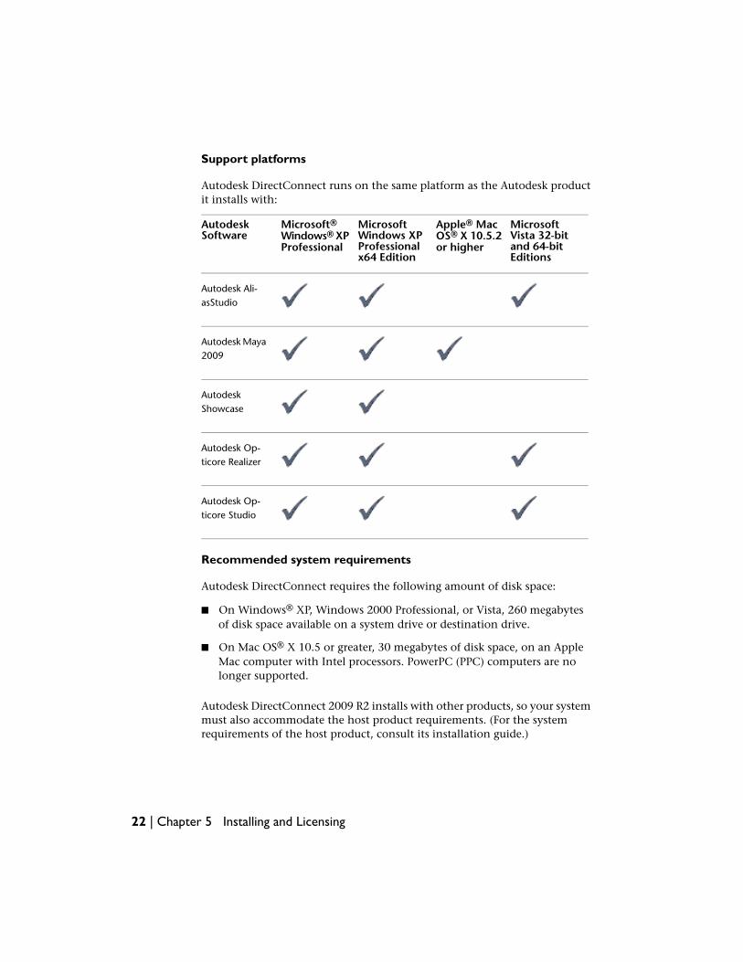
Support platforms
Autodesk DirectConnect runs on the same platform as the Autodesk productit installs with:
MicrosoftVista 32-bitand 64-bitEditions
Apple® MacOS® X 10.5.2or higher
MicrosoftWindows XPProfessionalx64 Edition
Microsoft®Windows® XPProfessional
AutodeskSoftware
Autodesk Ali-asStudio
Autodesk Maya2009
AutodeskShowcase
Autodesk Op-ticore Realizer
Autodesk Op-ticore Studio
Recommended system requirements
Autodesk DirectConnect requires the following amount of disk space:
■ On Windows® XP, Windows 2000 Professional, or Vista, 260 megabytesof disk space available on a system drive or destination drive.
■ On Mac OS® X 10.5 or greater, 30 megabytes of disk space, on an AppleMac computer with Intel processors. PowerPC (PPC) computers are nolonger supported.
Autodesk DirectConnect 2009 R2 installs with other products, so your systemmust also accommodate the host product requirements. (For the systemrequirements of the host product, consult its installation guide.)
22 | Chapter 5 Installing and Licensing
NOTE For the most up-to-date information on hardware qualifications, go tohttp://www.alias.com/eng/support/qualified_hardware/.
Setting up additional software (Autodesk Maya 2009)
NOTE Maya 2008 does not support the DirectConnect 2009 translator; however,it does support DirectConnect 2008. Seehttp://www.autodesk.com/maya-directconnect.
After you install your Maya 2009 software, load a plug-in to use AutodeskDirectConnect translators:
1 In Maya 2009, select Window > Settings/Preferences > Plug-in Manager.
2 Click the DirectConnect plug-in to enable all of the AutodeskDirectConnect translators:
■ Windows: DirectConnect.mll
■ Mac OS X: DirectConnect.lib
A check mark appears in the box.
Installing upgrades
You can download and install newer versions of Autodesk DirectConnect asthey become available on the Web.
1 Find the newest version on the Web and download its exe file. (See Findthe latest information on the Web (page 19).)
2 Remove the older version of Autodesk DirectConnect from your system.(In Windows, select Start > Settings > Control Panel and click the Addor Remove Programs choice.
3 Double-click the exe file you downloaded.
Software deployment using group policies forWindows
Disclaimer
The description of methods presented here is provided to aid those lookingfor a straight forward, Microsoft supported means for deployment of software
Software deployment using group policies for Windows | 23
over a Local Area Network. If the Microsoft Group Policy based mechanismdoes not provide sufficient control or features for the size or complexity ofyour network environment, we recommend that you consider more advancedMicrosoft solutions, or other third party solutions.
Introduction
Microsoft’s Active Directory technology provides the capability for softwareto be remotely installed from a server distribution point to client computers.The client computers must be members of an Organizational Unit (OU) inthe Active Directory. Software deployment is controlled by configuring theSoftware Installation policy of the Group Policy Object (GPO) associated withthat OU. The software installation occurs automatically at boot time; no userintervention is required.
Prerequisites
■ Active Directory must be installed and properly configured.
■ Client computers must have Microsoft Installer (MSI) version 3.0 or newerinstalled.
Configuration process
There are three main steps to deploying software using group policies:
1 Create a Distribution Point.
2 Assign the application to client computers.
3 Verify the installation.
NOTE Consult Microsoft Knowledge Base Article #816102 for more details,including information on how to redeploy or remove a package.
Create a distribution point
A distribution point is a shared network location containing the package(s)to install.
To create a distribution list
1 Log on to the appointed server as Administrator.
24 | Chapter 5 Installing and Licensing
2 Create a shared network folder.
3 Grant permissions as appropriate, Permission to modify the contents ofthis folder should typically be granted to an administrator or select groupof users; all other users should be restricted to read access.
4 Copy the .msi files for the package(s) to be deployed into this folder.
Assign a package to client computers
The Software Installation section of the Group Policy object specifies thesoftware packages to be deployed.
To assign a package for deployment
1 From the Windows Start menu on the server, click All Programs (orPrograms) > Administrative Tools > Active Directory Users and Computers.
2 Browse to the desired Organizational Unit (OU) in the Active Directorytree, right-click, and click Properties. The Properties dialog box for theOU selected displays.
NOTE For the Group Policy Object to take effect, the desired client computerobjects must be members of the OU selected.
3 Select the Group Policy tab and click New. Enter a name for the GPO.For example, “AliasStudio Computer Assigned Installation”. The GPO iscreated and added to the Group Policy Object Links list.
4 In the Group Policy Object Links list, click the GPO you just created, thenEdit.
5 In the left pane of the Group Policy Object Editor, under computerConfiguration, click the plus sign (+) next to the Software Settings folderto expand it.
6 Under Software Settings, right-click Software Installation, then click New> Package.
7 enter the UNC path to the desired package located in the distributionpoint created in the previous section, then click Open. For example,\server\share\AliasStudio.msi
NOTE Do not browse to the network location. You must type the UNC pathinto the “File name” text box.
Software deployment using group policies for Windows | 25
8 Select Assigned and click OK. Wait until an entry for the package isdisplayed in the right pane of the Group Policy window.
9 Repeat steps 7 and 8 for all packages to be deployed.
10 Close the Group Policy window and any other open Active Directorywindows.
The package is now assigned to all computers that are members of theOU for which the GPO has been created. The next time a computer inthe OU is restarted, the program will be installed and available for allusers of the computer.
NOTE Windows XP is shipped with Fast Logon Optimization enabled. Dueto this feature, two reboots are required before the software will be installed.Microsoft Knowledge Base Article #305293 describes the Fast LogonOptimization feature, along with instructions on how to disable it.
Test and verify the deployment
When a computer is restarted, the operating system displays messages aboutgroup policy, generally just before or after the Windows Login dialog box isdisplayed. These messages include the following:
■ Windows starting up
■ Applying computer settings
■ Installing managed software
■ Applying software installation settings
■ Loading your personal settings
■ Applying your personal settings
To verify that the package has been correctly assigned to a computer, restarta computer that is in the OU for which the GPO was created. The program isinstalled during the boot sequence, before the login prompt is displayed. Afterlogging in, the user should find the application under the Programs menu inthe same location as if it had been locally installed.
NOTE If problems arise, an entry is logged in the system’s Event Viewer underApplications.
26 | Chapter 5 Installing and Licensing
References
■ Microsoft Knowledge Base Article #816102: How to use Group Policy toRemotely Install Software in Windows Server 2003
■ Microsoft Knowledge Base Article #305293: Description of Windows XPProfessional Fast Logon Optimization Feature
Licensing Autodesk DirectConnectPurchasing and installing a license
1 To see if you need a license, go to Supported products and translators(page 4).
2 Purchase the Autodesk DirectConnect license, if necessary. Forinformation on how to purchase a license, go to the DirectConnect Websites. (See Find the latest information on the Web (page 19).)
NOTE For details on licensing (including how to use hardware locks andinstall floating licenses), refer to the installation and licensing documentationfor the Autodesk product you purchased.
3 From the Windows Start menu, select Programs > Autodesk >DirectConnect > Licensing and follow the instructions.
NOTE For details on licensing (including how to use hardware locks andinstall floating licenses), refer to the installation and licensing documentationfor the Autodesk product you purchased.
4 To verify the license installation, try to import a file (see the next topic).
Importing Files
NOTE When importing data into Showcase, you can filter the data, selecting onlythe portions you want.
When importing CAD files, the process is not always the same from onesoftware package to another. This section provides instructions on how to dothis in your Autodesk software.
Licensing Autodesk DirectConnect | 27
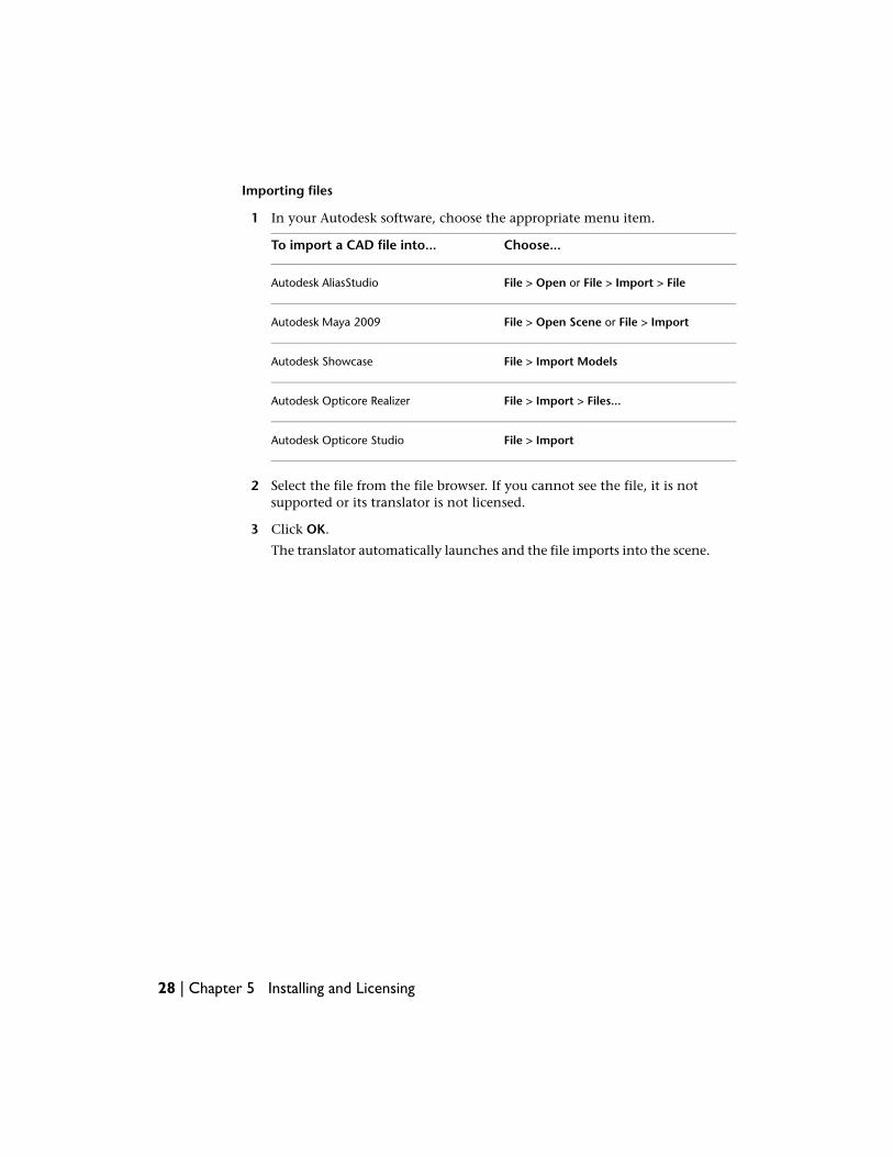
Importing files
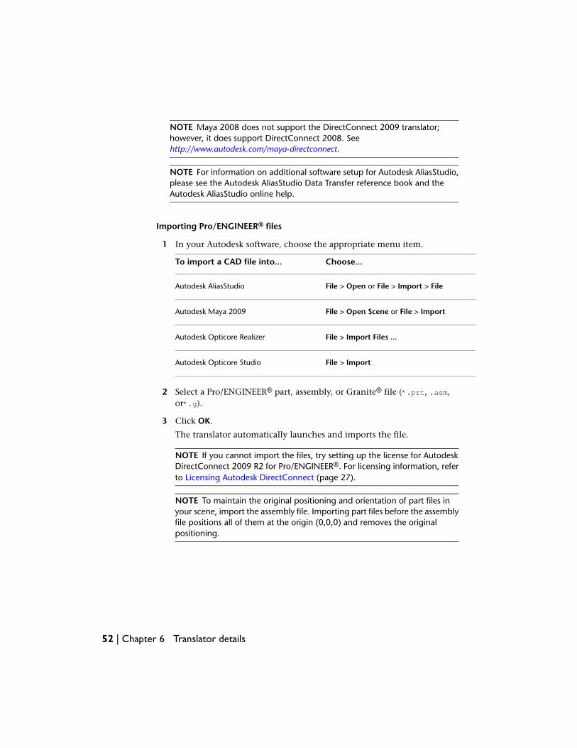
1 In your Autodesk software, choose the appropriate menu item.
Choose...To import a CAD file into...
File > Open or File > Import > FileAutodesk AliasStudio
File > Open Scene or File > ImportAutodesk Maya 2009
File > Import ModelsAutodesk Showcase
File > Import > Files...Autodesk Opticore Realizer
File > ImportAutodesk Opticore Studio
2 Select the file from the file browser. If you cannot see the file, it is notsupported or its translator is not licensed.
3 Click OK.
The translator automatically launches and the file imports into the scene.
28 | Chapter 5 Installing and Licensing

Translator details 6
29
CATIA® V5
CATIA® is computer-aided design software from Dassault Systèmes.
The software supports this format for Windows 32-bit and 64-bit operatingsystems.
NOTE For information on the Autodesk products that support this format andwhether you require a license, see Supported products and translators (page 4).
Software prerequisites
■ Install the Autodesk product where you plan to import files, using thisformat. (The Autodesk DirectConnect software installs at the same time.)
■ The software typically requires a license to import CATIA V5 files. For moreinformation on how to purchase a license, go to the DirectConnect Websites. (See Find the latest information on the Web (page 19).)To install a license, refer to the Install_DirectConnect.pdf document foundon the installation CD.
30 | Chapter 6 Translator details
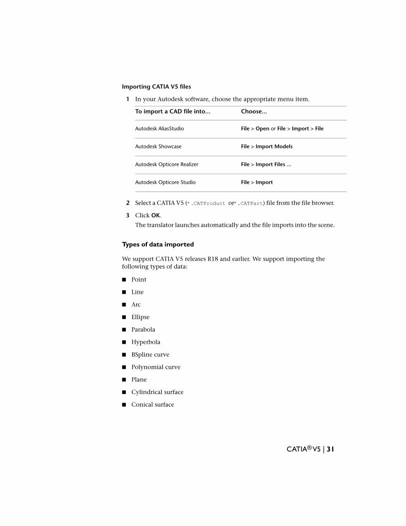
Importing CATIA V5 files
1 In your Autodesk software, choose the appropriate menu item.
Choose...To import a CAD file into...
File > Open or File > Import > FileAutodesk AliasStudio
File > Import ModelsAutodesk Showcase
File > Import Files ...Autodesk Opticore Realizer
File > ImportAutodesk Opticore Studio
2 Select a CATIA V5 (*.CATProduct or*.CATPart) file from the file browser.
3 Click OK.
The translator launches automatically and the file imports into the scene.
Types of data imported
We support CATIA V5 releases R18 and earlier. We support importing thefollowing types of data:
■ Point
■ Line
■ Arc
■ Ellipse
■ Parabola
■ Hyperbola
■ BSpline curve
■ Polynomial curve
■ Plane
■ Cylindrical surface
■ Conical surface
CATIA® V5 | 31
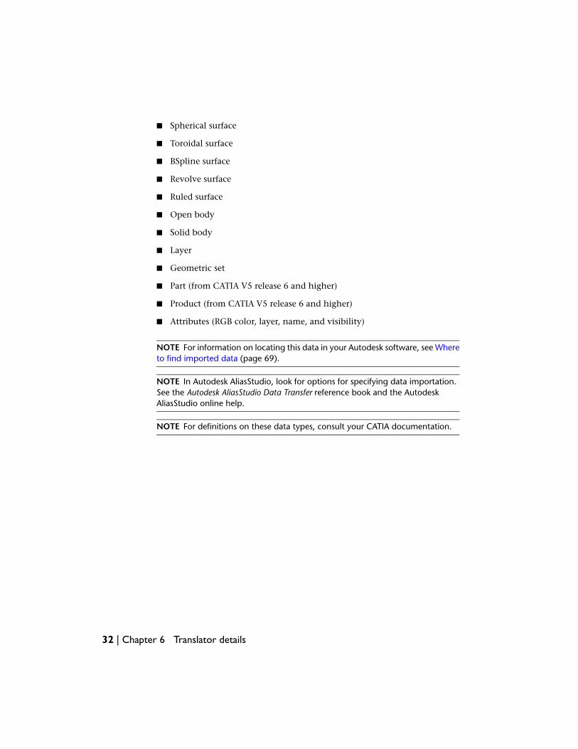
■ Spherical surface
■ Toroidal surface
■ BSpline surface
■ Revolve surface
■ Ruled surface
■ Open body
■ Solid body
■ Layer
■ Geometric set
■ Part (from CATIA V5 release 6 and higher)
■ Product (from CATIA V5 release 6 and higher)
■ Attributes (RGB color, layer, name, and visibility)
NOTE For information on locating this data in your Autodesk software, see Whereto find imported data (page 69).
NOTE In Autodesk AliasStudio, look for options for specifying data importation.See the Autodesk AliasStudio Data Transfer reference book and the AutodeskAliasStudio online help.
NOTE For definitions on these data types, consult your CATIA documentation.
32 | Chapter 6 Translator details
CATIA® V4
CATIA® is computer-aided design software from Dassault Systèmes.DirectConnect supports the importing of CATIA V4 geometric sets, attributes,such as names, layers, RGB colors, and visibility, as well as the following CATIAV4 file types:
■ .model
■ .mdl
■ .session
■ .exp
■ .dlv
■ .dlv3
■ .dlv4
NOTE DirectConnect supports CATIA model and export files produced with CATIAV4.xx and earlier V3RX Levels.
The software supports this format for Windows 32-bit and 64-bit operatingsystems.
NOTE For information on the Autodesk products that support this format andwhether you require a license, see Supported products and translators (page 4).
CATIA® V4 | 33
Software prerequisites
■ Install the Autodesk product where you plan to import files, using thisformat. (The Autodesk DirectConnect software installs at the same time.)
■ The software typically requires a license to import CATIA V4 files. For moreinformation on how to purchase a license, go to the DirectConnect Websites. (See Find the latest information on the Web (page 19).)To install a license, refer to the Install_DirectConnect.pdf document foundon the installation CD.
Importing CATIA V4 files
1 In your Autodesk software, choose the appropriate menu item.
Choose...To import a CAD file into...
File > Open or File > Import > FileAutodesk AliasStudio 2009 R1
File > Import ModelsAutodesk Showcase 2009 R1
File > ImportAutodesk Opticore Studio 2009 R1
2 Select a CATIA V4 (*.model, *.mdl, *.session, *.exp, *.dlvor *.dlv3)file from the file browser.
3 Click OK.
The translator launches automatically and the file imports into the scene.
Types of entities imported
We support importing the following SPACE (SP) entities:
■ Point (Type 1)
■ Line (Type 2)
■ Parametric curve (Type 3)
■ Plane (Type 4)
■ Parametric surface (Type 5)
■ Face (Type 6)
34 | Chapter 6 Translator details
■ Volume (Type 7)
■ Transformation (Type 9)
■ Edge (Type 12)
■ Circle (Type 20)
■ Ellipse (Type 21)
■ Parabola (Type 22)
■ Hyperbola (Type 23)
■ Compisite curve (Type 24)
■ Exact solid (Type 17, secondary type 2)
■ Parametric Skin (Type 35)
■ NURB Curve (Type 46)
■ NURB Surface (Type 47)
NOTE For information on locating this data in your Autodesk software, see Whereto find imported data (page 69).
NOTE In Autodesk AliasStudio, look for options for specifying data importation.See the Autodesk AliasStudio Data Transfer reference book and the AutodeskAliasStudio online help.
NOTE For definitions on these data types, consult your CATIA documentation.
CATIA® V4 | 35

Autodesk Inventor®
Autodesk DirectConnect lets you import Autodesk Inventor® part (*.ipt) andassembly (*.iam) files into supported Autodesk software, provided you haveInventor 2009 or the free Inventor View installed and licensed on yourmachine. We do not require an Autodesk Direct Connect license.
The software supports this format for Windows 32-bit operating systems.
Notes
■ Though Inventor data cannot be imported into a 64-bit version ofDirectConnect on a 64-bit OS, you can use the 32-bit version ofDirectConnect on a 64-bit OS to import Inventor files via DirectConnect.
■ To enable this translator on systems where no licensed Autodesk Inventor2009 product is available, download and install the free Inventor View2009 product fromhttp://usa.autodesk.com/adsk/servlet/index?id=10535296&siteID=123112.
■ Once the DirectConnect Inventor translator is installed, run it and selectFile > Open, before using DirectConnect to translate your data.However, if working on Vista and using the DirectConnect Inventortranslator, you must run the Inventor View as “administrator”, before thedata can be translated.
36 | Chapter 6 Translator details
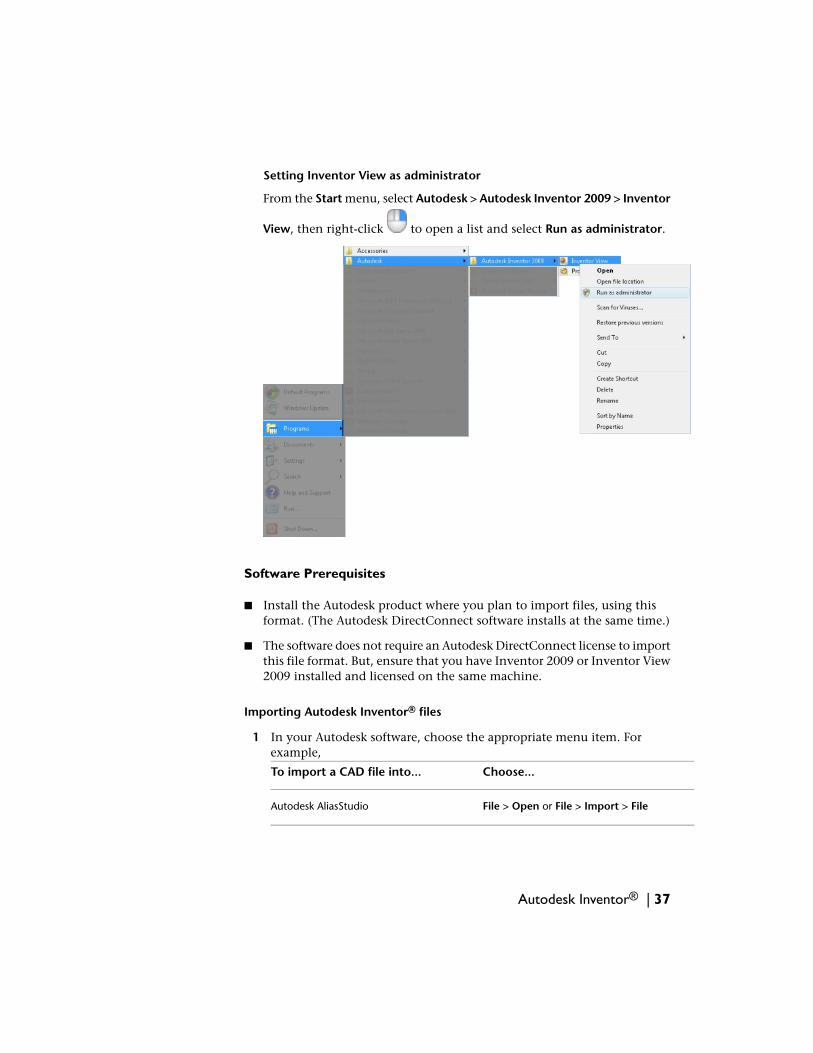
Setting Inventor View as administrator
From the Start menu, select Autodesk > Autodesk Inventor 2009 > Inventor
View, then right-click to open a list and select Run as administrator.
Software Prerequisites
■ Install the Autodesk product where you plan to import files, using thisformat. (The Autodesk DirectConnect software installs at the same time.)
■ The software does not require an Autodesk DirectConnect license to importthis file format. But, ensure that you have Inventor 2009 or Inventor View2009 installed and licensed on the same machine.
Importing Autodesk Inventor® files
1 In your Autodesk software, choose the appropriate menu item. Forexample,
Choose...To import a CAD file into...
File > Open or File > Import > FileAutodesk AliasStudio
Autodesk Inventor® | 37
Choose...To import a CAD file into...
File > Open Scene or File > ImportAutodesk Maya 2009
File > Import ModelsAutodesk Showcase
File > Import Files ...Autodesk Opticore Realizer
File > ImportAutodesk Opticore Studio
2 Browse to and select an Autodesk Inventor part or assembly file (*.iptor *.iam).
3 Click OK.
The translator automatically launches and imports the file.
NOTE To maintain the original positioning and orientation of part files inyour scene, import the assembly file. Importing part files before the assemblyfile positions all of them at the origin (0,0,0) and removes the originalpositioning.
Types of data imported
We import NURBS for this file format. The software maintains followingadditional information on import:
■ BREP Bodies
■ Data organization
■ Tolerances and units
■ Material Colors and simple transparency
NOTE For information on locating this data in your Autodesk software, see Whereto find imported data (page 69).
Limitations
■ WorkSources, Display Meshes, and 2D/3D Sketches get automaticallyexcluded when importing an Autodesk Inventor® file.
38 | Chapter 6 Translator details
■ Some cylindrical surfaces (pipes) do not trim properly.
DWG DXF
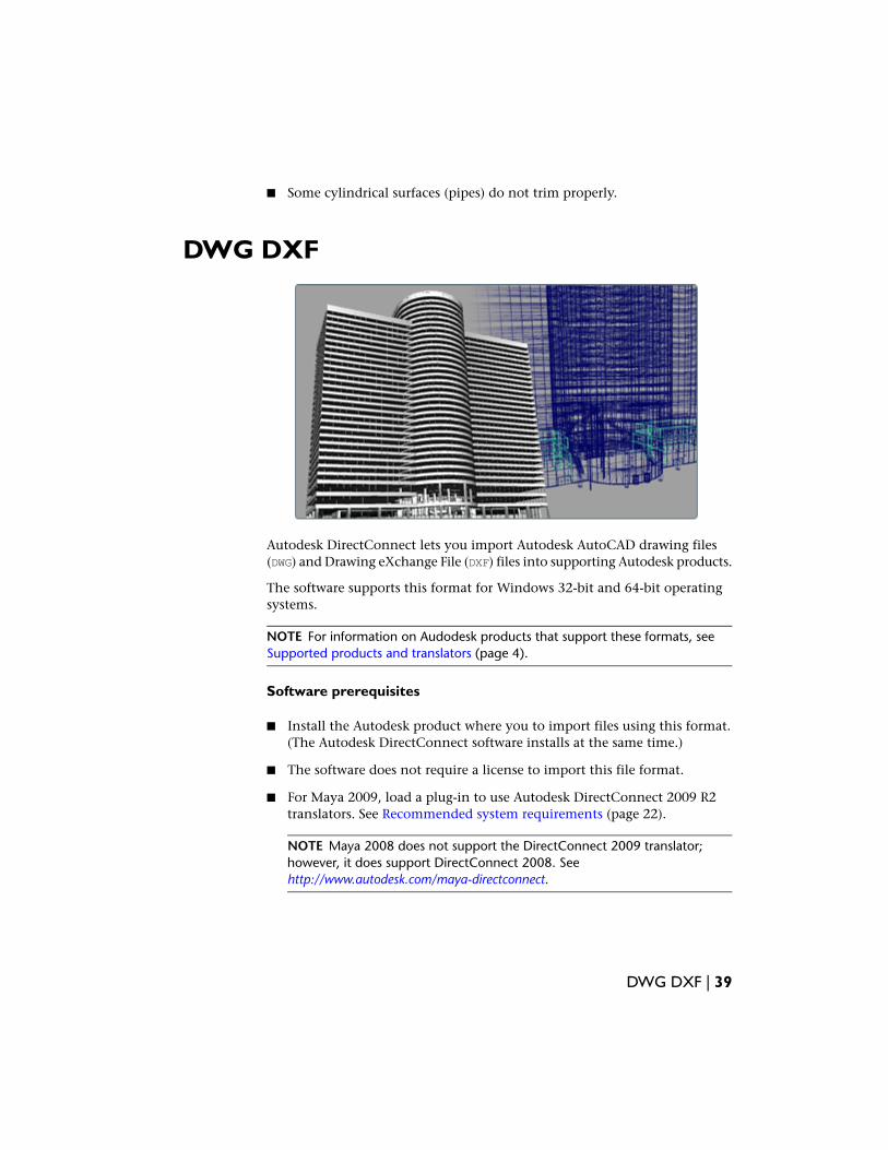
Autodesk DirectConnect lets you import Autodesk AutoCAD drawing files(DWG) and Drawing eXchange File (DXF) files into supporting Autodesk products.
The software supports this format for Windows 32-bit and 64-bit operatingsystems.
NOTE For information on Audodesk products that support these formats, seeSupported products and translators (page 4).
Software prerequisites
■ Install the Autodesk product where you to import files using this format.(The Autodesk DirectConnect software installs at the same time.)
■ The software does not require a license to import this file format.
■ For Maya 2009, load a plug-in to use Autodesk DirectConnect 2009 R2translators. See Recommended system requirements (page 22).
NOTE Maya 2008 does not support the DirectConnect 2009 translator;however, it does support DirectConnect 2008. Seehttp://www.autodesk.com/maya-directconnect.
DWG DXF | 39
Importing DWG/DXF files
1 In your Autodesk software, choose the appropriate menu item.
Choose...To import a CAD file into...
File > Open or File > Import > FileAutodesk AliasStudio
File > Open Scene or File > ImportAutodesk Maya 2009
File > Import ModelsAutodesk Showcase
File > Import Files ...Autodesk Opticore Realizer
File > ImportAutodesk Opticore Studio
2 Browse and select a DWG (.dwg) or DXF (.dxf) file.
3 Click OK.
The translator automatically launches and imports the file.
Types of data imported
We support the following types of DWG and DXF data:
■ Lines, arcs, and splines
■ Extruded curves
■ Extrusions
■ Layers
■ Meshes
■ Surfaces
■ Text
■ 3D solids
■ Materials
40 | Chapter 6 Translator details
NOTE For information on locating this data in your Autodesk software, see Whereto find imported data (page 69).
NOTE In Autodesk AliasStudio, look for options for specifying data importation.See the Autodesk AliasStudio Data Transfer reference book and the AutodeskAliasStudio online help.
NOTE DWG and DXF both support curves and round trip data export when wantcurves is set to ON. If they are not coming in, please check to ensure that wantcurves is enabled.
Exporting DWG/DXF files (Autodesk AliasStudio)
1 In your Autodesk software, choose the appropriate menu:
Choose ...To export a CAD file from ...
File > Save AsAutodesk AliasStudio
2 For details on the available options, use the Autodesk AliasStudio help.
IGES
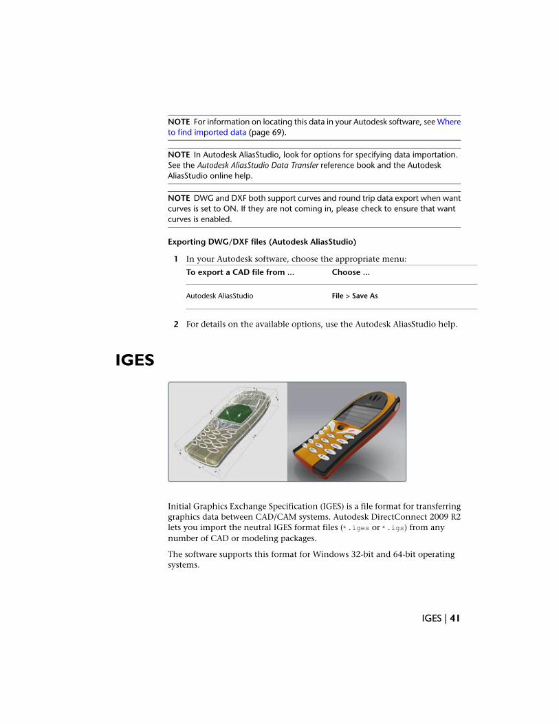
Initial Graphics Exchange Specification (IGES) is a file format for transferringgraphics data between CAD/CAM systems. Autodesk DirectConnect 2009 R2lets you import the neutral IGES format files (*.iges or *.igs) from anynumber of CAD or modeling packages.
The software supports this format for Windows 32-bit and 64-bit operatingsystems.
IGES | 41
For information on the Autodesk products that support this format, go toSupported products and translators (page 4).
NOTE Maya 2009 supports this translator on the Mac OS X operating system.
Software prerequisites
■ Install one of Autodesk AliasStudio, Autodesk Maya 2009, or AutodeskShowcase. (The Autodesk DirectConnect software installs at the same time.)
■ The software does not require a license to import this file format.
■ For Maya 2009, load a plug-in to use Autodesk DirectConnect 2009 R2translators. See Recommended system requirements (page 22).
NOTE Maya 2008 does not support the DirectConnect 2009 translator;however, it does support DirectConnect 2008. Seehttp://www.autodesk.com/maya-directconnect.
NOTE For information on additional software setup for Autodesk AliasStudio,please see the Autodesk AliasStudio Data Transfer reference book and theAutodesk AliasStudio online help.
Additional software setup (Autodesk AliasStudio)
For Autodesk AliasStudio Version 13.0.2, set the IGES system environmentvariable to use the latest IGES translator:
1 From your Windows toolbar, select Start > Settings > Control Panel.
2 Double click System. The Systems Properties window opens.
3 Click the Advanced tab.
4 Click theEnvironment Variables button.
5 Click New and enter the following information:
■ For Variable name, IGES
■ For Variable value, 1
42 | Chapter 6 Translator details
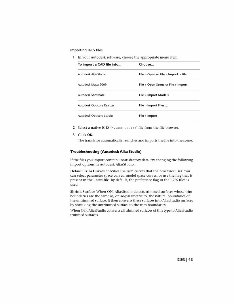
Importing IGES files
1 In your Autodesk software, choose the appropriate menu item.
Choose...To import a CAD file into...
File > Open or File > Import > FileAutodesk AliasStudio
File > Open Scene or File > ImportAutodesk Maya 2009
File > Import ModelsAutodesk Showcase
File > Import Files ...Autodesk Opticore Realizer
File > ImportAutodesk Opticore Studio
2 Select a native IGES (*.iges or .igs) file from the file browser.
3 Click OK.
The translator automatically launches and imports the file into the scene.
Troubleshooting (Autodesk AliasStudio)
If the files you import contain unsatisfactory data, try changing the followingimport options in Autodesk AliasStudio:
Default Trim Curves Specifies the trim curves that the processor uses. Youcan select parameter space curves, model space curves, or use the flag that ispresent in the .IGES file. By default, the preference flag in the IGES files isused.
Shrink Surface When ON, AliasStudio detects trimmed surfaces whose trimboundaries are the same as, or iso-parametric to, the natural boundaries ofthe untrimmed surface. It then converts these surfaces into AliasStudio surfacesby shrinking the untrimmed surface to the trim boundaries.
When OFF, AliasStudio converts all trimmed surfaces of this type to AliasStudiotrimmed surfaces.
IGES | 43
Types of data imported
The Autodesk DirectConnect 2009 R2 for IGES translator imports ASCII formatIGES files with or without linefeed characters at the end of each record. Thesoftware does not support Binary IGES files.
The software imports NURBS for this file format and maintains the followinginformation on import:
■ Surfaces and curves
■ Data organization (groups, layers, visibility, and instances)
■ Units
■ Colors
NOTE For information on this data in your Autodesk software, see Where to findimported data (page 69).
NOTE Check the options in AliasStudio to specifying data importation. See theAutodesk AliasStudio Data Transfer reference book and the Autodesk AliasStudioonline help.
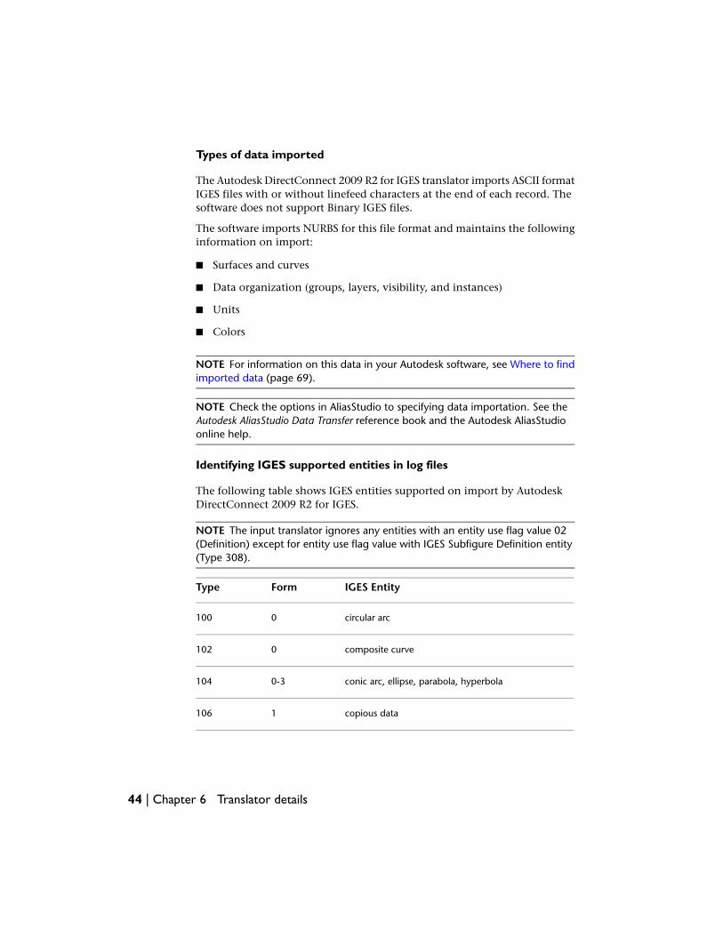
Identifying IGES supported entities in log files
The following table shows IGES entities supported on import by AutodeskDirectConnect 2009 R2 for IGES.
NOTE The input translator ignores any entities with an entity use flag value 02(Definition) except for entity use flag value with IGES Subfigure Definition entity(Type 308).
IGES EntityFormType
circular arc0100
composite curve0102
conic arc, ellipse, parabola, hyperbola0-3104
copious data1106
44 | Chapter 6 Translator details
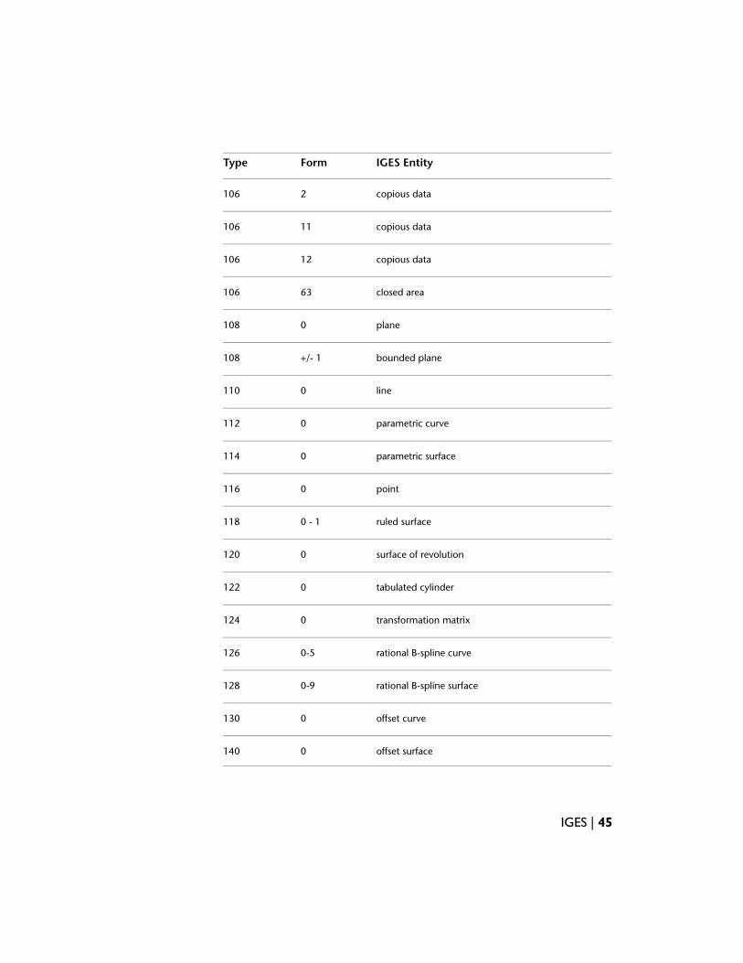
IGES EntityFormType
copious data2106
copious data11106
copious data12106
closed area63106
plane0108
bounded plane+/- 1108
line0110
parametric curve0112
parametric surface0114
point0116
ruled surface0 - 1118
surface of revolution0120
tabulated cylinder0122
transformation matrix0124
rational B-spline curve0-5126
rational B-spline surface0-9128
offset curve0130
offset surface0140
IGES | 45
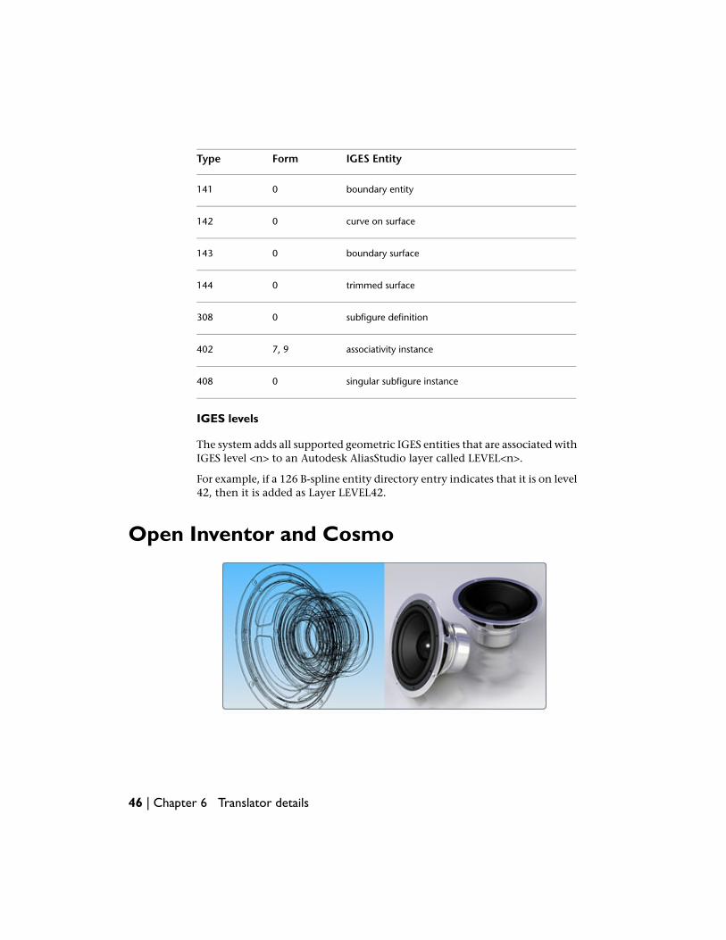
IGES EntityFormType
boundary entity0141
curve on surface0142
boundary surface0143
trimmed surface0144
subfigure definition0308
associativity instance7, 9402
singular subfigure instance0408
IGES levels
The system adds all supported geometric IGES entities that are associated withIGES level <n> to an Autodesk AliasStudio layer called LEVEL<n>.
For example, if a 126 B-spline entity directory entry indicates that it is on level42, then it is added as Layer LEVEL42.
Open Inventor and Cosmo
46 | Chapter 6 Translator details
Autodesk DirectConnect 2009 R2 lets you import Open Inventor™ ASCII orbinary files (*.iv) or Cosmo™ scene binary files (*.csb) into supportedAutodesk software.
(Open Inventor is a 3D file format from Silicon Graphics Inc. with no relationto Autodesk Inventor® software.)
NOTE For information on the Autodesk products that support these formats, seethe Supported products and translators (page 4).
Software prerequisites
■ Install the Autodesk product where you plan to import files using theseformats. (The Autodesk DirectConnect software installs at the same time.)
■ The software does not require a license to import these file formats.
Importing Open Inventor or Cosmo files
1 Choose the appropriate menu choice.
Choose...To import a CAD file into...
File > Open or File > Import > FileAutodesk AliasStudio
File > Open Scene or File > ImportAutodesk Maya 2009
File > Import ModelsAutodesk Showcase
File > Import Files ...Autodesk Opticore Realizer
File > ImportAutodesk Opticore Studio
2 Browse to and select an Open Inventor (*.iv) or Cosmo (.csb) file.
3 Click OK.
The translator automatically launches and imports the file.
Open Inventor and Cosmo | 47
Type of data imported
The software imports polygons and NURBS for these file formats and maintainsthe following information on import:
■ Data organization (parent, child, and groups)
■ Units
■ Materials
■ Textures
■ Polygonal Shapes
■ Tranformation nodes
NOTE For information on locating this data in your Autodesk software, see Whereto find imported data (page 69).
Limitations
■ When importing Open Inventor files, the system automatically excludeslines, cameras, lights, manipulators, tolerances, and animation.
■ The software only supports this format for Windows 32-bit operatingsystems.
JT
48 | Chapter 6 Translator details
The JT Open Program develops and supports the DirectModel format JT. It isa format for the visualization of 3D models.
The software supports this format for Windows 32-bit and 64-bit operatingsystems.
NOTE For information on the Autodesk products that support this format and ifyou need a license, go to Supported products and translators (page 4).
Software prerequisites
■ Install the Autodesk product where you plan to import files using theseformats. (The Autodesk DirectConnect software installs at the same time.)
■ The software requires a license.For more information on how to purchase a license, go to theDirectConnect Web site. (See Find the latest information on the Web (page19).) To install a license, refer to the Install_DirectConnect.pdf documentfound on the installation CD.
Importing JT files
1 In your Autodesk software, choose the appropriate menu item.
Choose...To import a CAD file into...
File > Open or File > Import > FileAutodesk AliasStudio
File > Import ModelsAutodesk Showcase
File > Import Files ...Autodesk Opticore Realizer
File > ImportAutodesk Opticore Studio
2 Select a (*.jt) file from the file browser.
3 Click OK.
The translator automatically launches and imports the file into the scene.
JT | 49
Type of data imported
The software maintains the following information when importing JT files:
■ Precise geometric data conversion
■ Data organization (parent and child hierarchal data, visibility, andinstances)
■ Units
■ Levels of detail (degrees of tesselation)
■ Materials (brightness (shininess), ambient color, specular color, diffusecolor, and emission color)
■ Textures (embedded image files)
■ XTBREP and BREP topology
NOTE For information on locating this data in your Autodesk software, see Whereto find imported data (page 69).
NOTE In Autodesk AliasStudio, look for options for specifying data importation.See the Autodesk AliasStudio Data Transfer reference book and the AutodeskAliasStudio online help.
Limitations
■ Import options are not available.
■ The software automatically excludes curve geometry and animation whenimporting a JT file.
50 | Chapter 6 Translator details
Pro/ENGINEER®
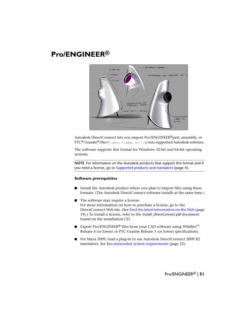
Autodesk DirectConnect lets you import Pro/ENGINEER®part, assembly, orPTC® Granite® files (*.prt, *.asm, or *.g) into supported Autodesk software.
The software supports this format for Windows 32-bit and 64-bit operatingsystems.
NOTE For information on the Autodesk products that support this format and ifyou need a license, go to Supported products and translators (page 4).
Software prerequisites
■ Install the Autodesk product where you plan to import files using theseformats. (The Autodesk DirectConnect software installs at the same time.)
■ The software may require a license.For more information on how to purchase a license, go to theDirectConnect Web site. (See Find the latest information on the Web (page19).) To install a license, refer to the Install_DirectConnect.pdf documentfound on the installation CD.
■ Export Pro/ENGINEER® files from your CAD software using Wildfire™
Release 4 (or lower) or PTC Granite Release 5 (or lower) specifications.
■ For Maya 2009, load a plug-in to use Autodesk DirectConnect 2009 R2translators. See Recommended system requirements (page 22).
Pro/ENGINEER® | 51
NOTE Maya 2008 does not support the DirectConnect 2009 translator;however, it does support DirectConnect 2008. Seehttp://www.autodesk.com/maya-directconnect.
NOTE For information on additional software setup for Autodesk AliasStudio,please see the Autodesk AliasStudio Data Transfer reference book and theAutodesk AliasStudio online help.
Importing Pro/ENGINEER® files
1 In your Autodesk software, choose the appropriate menu item.
Choose...To import a CAD file into...
File > Open or File > Import > FileAutodesk AliasStudio
File > Open Scene or File > ImportAutodesk Maya 2009
File > Import Files ...Autodesk Opticore Realizer
File > ImportAutodesk Opticore Studio
2 Select a Pro/ENGINEER® part, assembly, or Granite® file (*.prt, .asm,or*.g).
3 Click OK.
The translator automatically launches and imports the file.
NOTE If you cannot import the files, try setting up the license for AutodeskDirectConnect 2009 R2 for Pro/ENGINEER®. For licensing information, referto Licensing Autodesk DirectConnect (page 27).
NOTE To maintain the original positioning and orientation of part files inyour scene, import the assembly file. Importing part files before the assemblyfile positions all of them at the origin (0,0,0) and removes the originalpositioning.
52 | Chapter 6 Translator details
Type of data imported
The software imports NURBS for this file format and maintains the followingdata on import:
■ Precise geometric surface and topology information
■ Data organization
■ Tolerances and units.
NOTE For information on locating this data in your Autodesk software, see Whereto find imported data (page 69).
NOTE In Autodesk AliasStudio, look for options for specifying data importation.See the Autodesk AliasStudio Data Transfer reference book and the AutodeskAliasStudio online help.
Limitations
■ The software changes node names based on geometry, assembly, or partnames.
■ When importing a Pro/ENGINEER® file, the software automatically excludesconstruction history, lines, and animation.
■ Granite does not support layers or curves.
Pro/ENGINEER® | 53
SolidWorks®
Autodesk DirectConnect 2009 R2 lets you import SolidWorks® part andassembly files (*.sldprt and *.sldasm) into supported Autodesk software,provided you have SolidWorks® installed, licensed on your machine, andrunning. The software does not require an Autodesk DirectConnect license.
NOTE For information on the Autodesk products that support this format and ifyou need a license, go to Supported products and translators (page 4).
Software prerequisites
■ Install the Autodesk product where you plan to import files using theseformats. (The Autodesk DirectConnect software installs at the same time.)
■ The software does not require an Autodesk DirectConnect license to importthis file format. Install and license SolidWorks® Versions 2005, 2006, 2007,or 2008 on the same machine.
■ For Maya 2009, load a plug-in to use Autodesk DirectConnect 2009 R2translators. See Recommended system requirements (page 22).
NOTE Maya 2008 does not support the DirectConnect 2009 translator;however, it does support DirectConnect 2008. Seehttp://www.autodesk.com/maya-directconnect.
54 | Chapter 6 Translator details
NOTE For information on additional software setup for Autodesk AliasStudio,please see the Autodesk AliasStudio Data Transfer reference book and theAutodesk AliasStudio online help.
Importing SolidWorks® files
1 In your Autodesk software, choose the appropriate menu item.
Choose...To import a CAD file into...
File > Open or File > Import > FileAutodesk AliasStudio
File > Open Scene or File > ImportAutodesk Maya 2009
File > Import ModelsAutodesk Showcase
File > Import Files ...Autodesk Opticore Realizer
File > ImportAutodesk Opticore Studio
2 Select a SolidWorks® part or assembly file(*.sldprt or *.sldasm). (If youcannot see the files, start the SolidWorks® software, minimize its window,and then try again to open the files.)
3 Click OK.
The translator automatically launches and imports the file into the scene.
NOTE To maintain the original positioning and orientation of part files inyour scene, import the assembly file. Importing part files before the assemblyfile positions all of them at the origin (0,0,0) and removes the originalpositioning.
Type of data imported
The software imports NURBS for this file format and maintains the followinginformation on import:
■ Precise geometric surface and topology information
■ Data organization
SolidWorks® | 55
■ Tolerances and unit
■ Colors
NOTE For information on locating this data in your Autodesk software, see Whereto find imported data (page 69).
NOTE In Autodesk AliasStudio, look for options for specifying data importation.See the Autodesk AliasStudio Data Transfer reference book and the AutodeskAliasStudio online help.
Limitations
■ The software automatically excludes construction history, lines, andanimation when importing a SolidWorks® file.
■ The software only supports this format for Windows 32-bit operatingsystems.
STEP
Autodesk DirectConnect 2009 R2 lets you import STEP files (*.stpor *.step).The software does not require a Autodesk DirectConnect 2009 R2 license.
The software supports this format for Windows 32-bit and 64-bit operatingsystems.
56 | Chapter 6 Translator details
NOTE Maya 2009 supports this translator on the Mac OS X operating system.
NOTE For information on the Autodesk products that support this format, go toSupported products and translators (page 4).
Software prerequisites
■ Install the Autodesk product where you plan to import files using theseformats. (The Autodesk DirectConnect software installs at the same time.)
■ Export STEP files from the CAD software using AP203 or AP214specifications.
■ The software does not require a license to import this file format.For more information on how to purchase a license, go to theDirectConnect Web site. (See Find the latest information on the Web (page19).) To install a license, refer to the Install_DirectConnect.pdf documentfound on the installation CD.
Importing STEP files
1 In your Autodesk software, choose the appropriate menu item.
Choose...To import a CAD file into...
File > Open or File > Import > FileAutodesk AliasStudio
File > Open Scene or File > ImportAutodesk Maya 2009
File > Import ModelsAutodesk Showcase
File > Import Files ...Autodesk Opticore Realizer
File > ImportAutodesk Opticore Studio
2 Select a native STEP (*.stp or *.step) file from the file browser.
3 Click OK.
The translator automatically launches and imports the file into the scene.
STEP | 57
Type of data imported
The software imports NURBS for this file format and maintains the followinginformation on import:
■ Precise geometric surface and topology information (ISO 10303:42)
■ Data organization (layers)
■ Tolerances and units
■ Colors
NOTE For information on locating this data in your Autodesk software, see Whereto find imported data.
NOTE In Autodesk AliasStudio, look for options for specifying data importation.See the Autodesk AliasStudio Data Transfer reference book and the AutodeskAliasStudio online help.
Limitations
■ When importing a STEP file, the software automatically excludesconstruction lines, modeling curves, and animation.
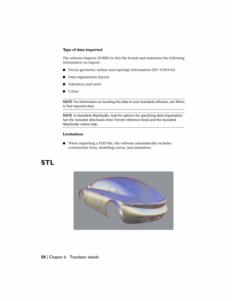
STL
58 | Chapter 6 Translator details
Autodesk DirectConnect 2009 R2 lets you import STL files. The software doesnot require a Autodesk DirectConnect 2009 R2 license.
The software supports this format for Windows 32-bit and 64-bit operatingsystems.
NOTE For information on the Autodesk products that support this format and ifyou need a license, go to Supported products and translators (page 4)section ofWhat is Autodesk DirectConnect?
Software prerequisites
■ Install the Autodesk product where you plan to import files using theseformats. (The Autodesk DirectConnect software installs at the same time.)
■ The software does not require a license.For Maya 2009, load a plug-in to used Autodesk DirectConnect translator.See Recommended system requirements (page 22).
NOTE Maya 2008 does not support the DirectConnect 2009 translator;however, it does support DirectConnect 2008. Seehttp://www.autodesk.com/maya-directconnect.
NOTE Maya 2009 supports this translator on the Macintoesh OS X operatingsystem.
Importing STL files
1 In your Autodesk software, choose the appropriate menu item.
Choose...To import a CAD file into...
File > Open Scene or File > ImportAutodesk Maya 2009
File > Import ModelsAutodesk Showcase
File > Import Files ...Autodesk Opticore Realizer
File > ImportAutodesk Opticore Studio
2 Select a native STL (Stereolithography) file from the file browser.
STL | 59
3 Click OK.
The translator automatically launches and imports the file into the scene.
Type of data imported
ASCII and binary STL files are supported.
NOTE For information on locating this data in your Autodesk software, see Whereto find imported data.
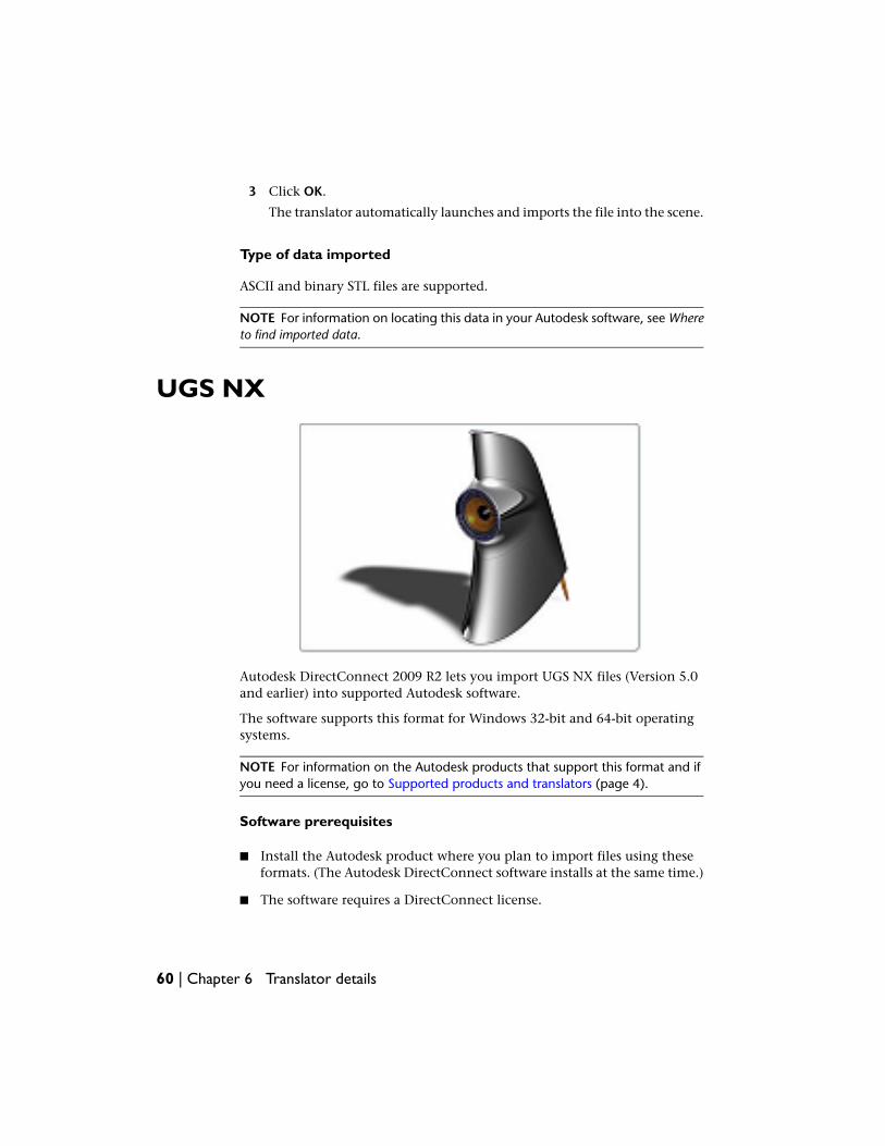
UGS NX
Autodesk DirectConnect 2009 R2 lets you import UGS NX files (Version 5.0and earlier) into supported Autodesk software.
The software supports this format for Windows 32-bit and 64-bit operatingsystems.
NOTE For information on the Autodesk products that support this format and ifyou need a license, go to Supported products and translators (page 4).
Software prerequisites
■ Install the Autodesk product where you plan to import files using theseformats. (The Autodesk DirectConnect software installs at the same time.)
■ The software requires a DirectConnect license.
60 | Chapter 6 Translator details
For more information on how to purchase a license, go to theDirectConnect Web site. (See Installing and Licensing (page 3).) To installa license, refer to the Install_DirectConnect.pdf document found on theinstallation CD.
Importing UGS NX files
1 In your Autodesk import files, choose the appropriate menu item.
Choose...To import a CAD file into...
File > Open or File > Import > FileAutodesk AliasStudio
File > Open Scene or File > ImportAutodesk Maya 2009
File > Import ModelsAutodesk Showcase
File > Import Files ...Autodesk Opticore Realizer
File > ImportAutodesk Opticore Studio
2 Select a (*.prt) file from the file browser. (The software supports UGSNX part and assembly (.prt) files version V13.0 to NX 5.0.)
NOTE There are options in Autodesk AliasStudio for you to specify dataimportation. For details, see the Autodesk AliasStudio Data Transfer referencebook and the Autodesk AliasStudio online help.
3 Click OK.
The translator automatically launches and imports the file into the scene.
Exporting UGS NX files (Autodesk AliasStudio)
To export UGS NX files from Autodesk AliasStudio:
1 In your Autodesk software, choose the appropriate menu:
Choose...To export a CAD file from...
File > Save AsAutodesk AliasStudio
UGS NX | 61
2 Go to the Autodesk AliasStudio documentation for more details on howto build a model in for maximum compatibility between UGS NX andAutodesk AliasStudio.
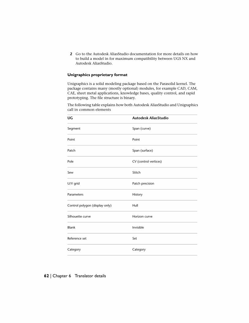
Unigraphics proprietary format
Unigraphics is a solid modeling package based on the Parasolid kernel. Thepackage contains many (mostly optional) modules, for example CAD, CAM,CAE, sheet metal applications, knowledge bases, quality control, and rapidprototyping. The file structure is binary.
The following table explains how both Autodesk AliasStudio and Unigraphicscall in common elements
Autodesk AliasStudioUG
Span (curve)Segment
PointPoint
Span (surface)Patch
CV (control vertices)Pole
StitchSew
Patch precisionU/V grid
HistoryParameters
HullControl polygon (display only)
Horizon curveSilhouette curve
InvisibleBlank
SetReference set
CategoryCategory
62 | Chapter 6 Translator details
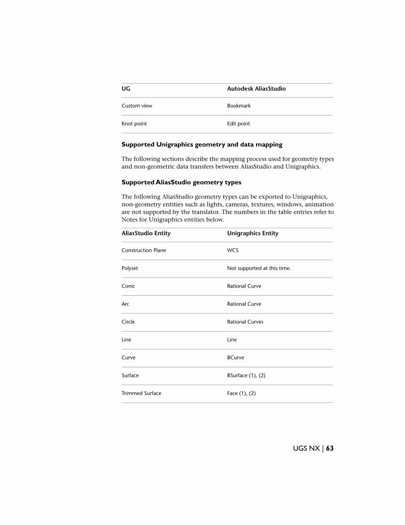
Autodesk AliasStudioUG
BookmarkCustom view
Edit pointKnot point
Supported Unigraphics geometry and data mapping
The following sections describe the mapping process used for geometry typesand non-geometric data transfers between AliasStudio and Unigraphics.
Supported AliasStudio geometry types
The following AliasStudio geometry types can be exported to Unigraphics,non-geometry entities such as lights, cameras, textures, windows, animationare not supported by the translator. The numbers in the table entries refer toNotes for Unigraphics entities below.
Unigraphics EntityAliasStudio Entity
WCSConstruction Plane
Not supported at this time.Polyset
Rational CurveConic
Rational CurveArc
Rational CurvesCircle
LineLine
BCurveCurve
BSurface (1), (2)Surface
Face (1), (2)Trimmed Surface
UGS NX | 63
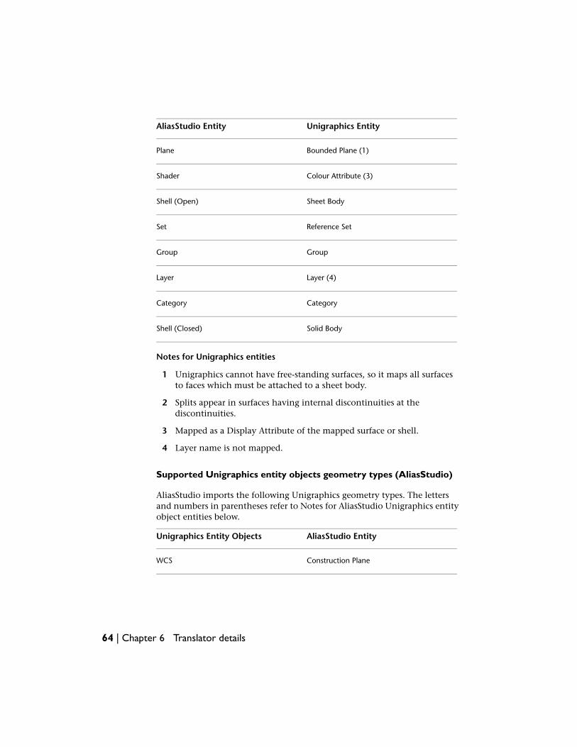
Unigraphics EntityAliasStudio Entity
Bounded Plane (1)Plane
Colour Attribute (3)Shader
Sheet BodyShell (Open)
Reference SetSet
GroupGroup
Layer (4)Layer
CategoryCategory
Solid BodyShell (Closed)
Notes for Unigraphics entities
1 Unigraphics cannot have free-standing surfaces, so it maps all surfacesto faces which must be attached to a sheet body.
2 Splits appear in surfaces having internal discontinuities at thediscontinuities.
3 Mapped as a Display Attribute of the mapped surface or shell.
4 Layer name is not mapped.
Supported Unigraphics entity objects geometry types (AliasStudio)
AliasStudio imports the following Unigraphics geometry types. The lettersand numbers in parentheses refer to Notes for AliasStudio Unigraphics entityobject entities below.
AliasStudio EntityUnigraphics Entity Objects
Construction PlaneWCS
64 | Chapter 6 Translator details
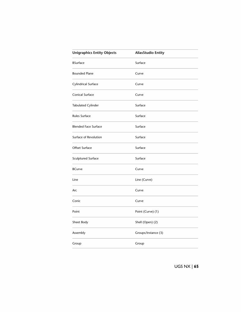
AliasStudio EntityUnigraphics Entity Objects
SurfaceBSurface
CurveBounded Plane
CurveCylindrical Surface
CurveConical Surface
SurfaceTabulated Cylinder
SurfaceRules Surface
SurfaceBlended Face Surface
SurfaceSurface of Revolution
SurfaceOffset Surface
SurfaceSculptured Surface
CurveBCurve
Line (Curve)Line
CurveArc
CurveConic
Point (Curve) (1)Point
Shell (Open) (2)Sheet Body
Groups/Instance (3)Assembly
GroupGroup
UGS NX | 65
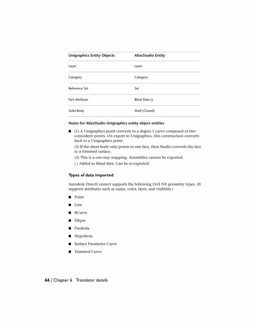
AliasStudio EntityUnigraphics Entity Objects
LayerLayer
CategoryCategory
SetReference Set
Blind Data ()Part Attribute
Shell (Closed)Solid Body
Notes for AliasStudio Unigraphics entity object entities
■ (1) A Unigraphics point converts to a degree 1 curve composed of twocoincident points. On export to Unigraphics, this construction convertsback to a Unigraphics point.
(2) If the sheet body only points to one face, then Studio converts the faceto a trimmed surface.
(3) This is a one-way mapping. Assemblies cannot be exported.
( ) Added as blind data. Can be re-exported.
Types of data imported
Autodesk DirectConnect supports the following UGS NX geometry types. (Itsupports attributes such as name, color, layer, and visibility.)
■ Point
■ Line
■ BCurve
■ Ellipse
■ Parabola
■ Hyperbola
■ Surface Parameter Curve
■ Trimmed Curve
66 | Chapter 6 Translator details
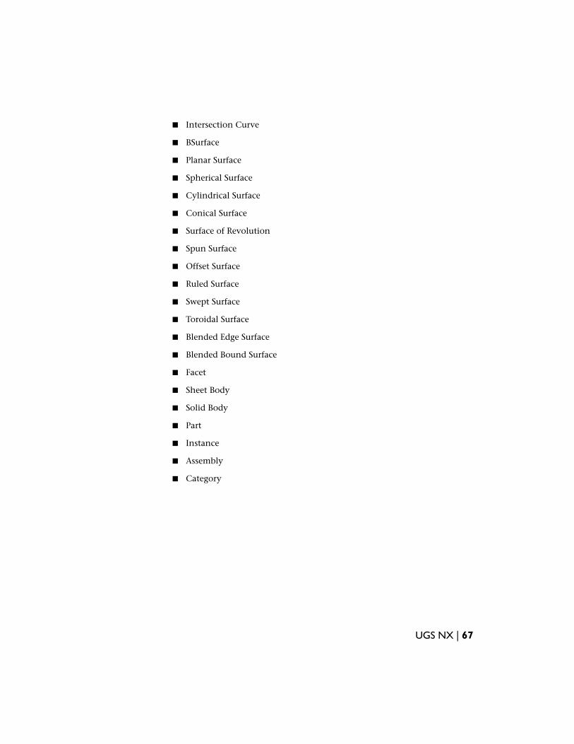
■ Intersection Curve
■ BSurface
■ Planar Surface
■ Spherical Surface
■ Cylindrical Surface
■ Conical Surface
■ Surface of Revolution
■ Spun Surface
■ Offset Surface
■ Ruled Surface
■ Swept Surface
■ Toroidal Surface
■ Blended Edge Surface
■ Blended Bound Surface
■ Facet
■ Sheet Body
■ Solid Body
■ Part
■ Instance
■ Assembly
■ Category
UGS NX | 67

68
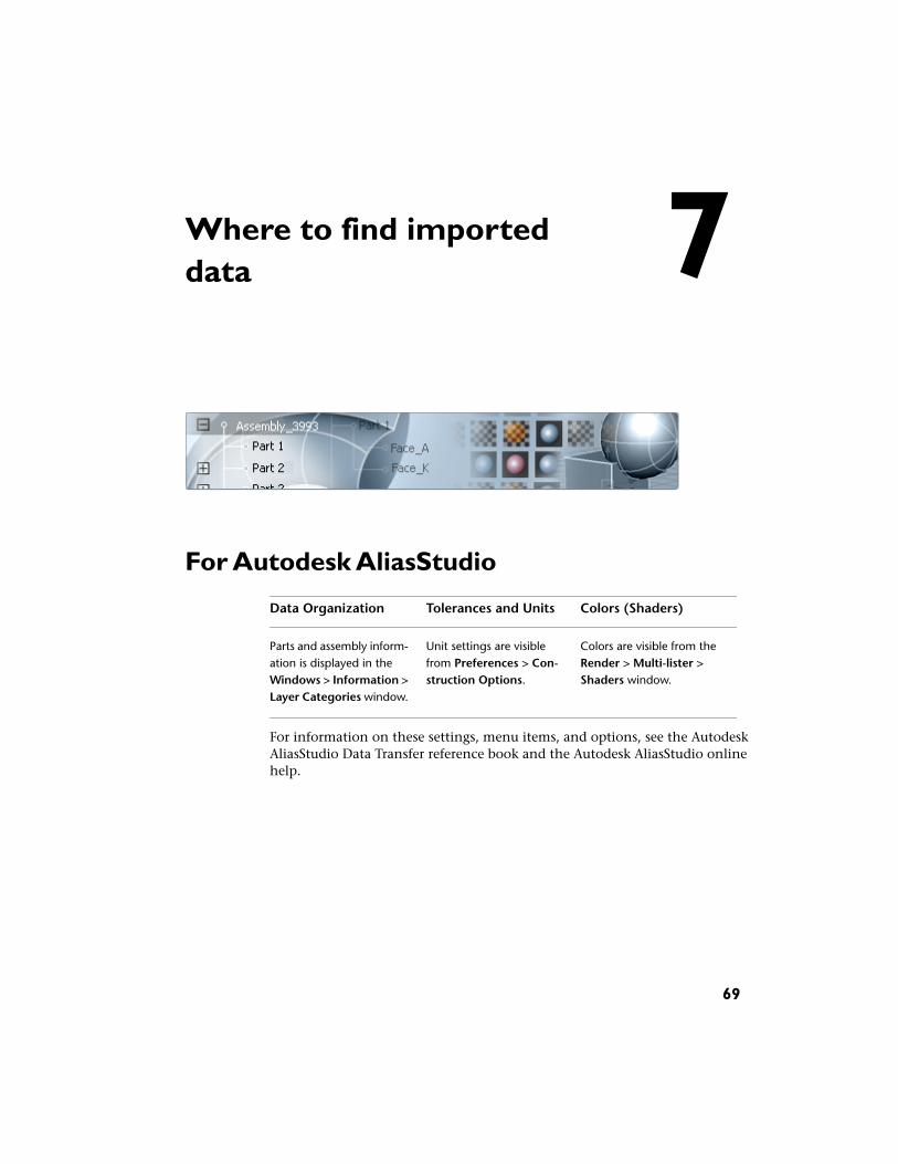
Where to find importeddata
For Autodesk AliasStudio
Colors (Shaders)Tolerances and UnitsData Organization
Colors are visible from theRender > Multi-lister >Shaders window.
Unit settings are visiblefrom Preferences > Con-struction Options.
Parts and assembly inform-ation is displayed in theWindows > Information >Layer Categories window.
For information on these settings, menu items, and options, see the AutodeskAliasStudio Data Transfer reference book and the Autodesk AliasStudio onlinehelp.
7
69
For Autodesk Maya 2009
NOTE Maya 2008 does not support the DirectConnect 2009 translator; however,it does support DirectConnect 2008. Seehttp://www.autodesk.com/maya-directconnect.
Colors (Shaders)Tolerances and UnitsData Organization
Colors are imported asshaders and are visible for
Unit settings are visiblefrom Window > Set-
Layer information is visiblefrom either the Display >
either the Window > Ren-tings/Preferences > Prefer-ences.
UI Elements > ChannelBox/Layer Editor menu or dering Editors > Hyper-
Open the Categories taband choose Settings to
the Window > Relation-ship Editors > DisplayLayers menu.
shade or Window > Ren-dering Editors > Multil-ister window.change the Working Units
and Tolerances.Part and assembly informa-tion is visible for either theWindow > Outliner menuor the Window > Hyper-graph menu.
For more information on these setting and menu items, see the AutodeskMaya online help.
For Autodesk Showcase
Colors (Shaders)Tolerances and UnitsData Organization
Colors are imported asmaterials and are visible
Unit settings are visible fromEdit > Model settings. Try
Layers, parts, and assemblyhierarchies appear in the
from Material > MaterialProperties.
setting the tessellation ornumber of levels of detail(LODs) on file import.
Organizer window (Scene> Organizer).This window shows the ori-ginal file hierarchy and lets To see the number of LODs
for a loaded file, select Op-you create your own ar-tions > Performance andrangements of objects. YouQuality. Next, click thecan view and change theLock display quality tostate of objects from visible
to hidden to deleted. button and move the slider
70 | Chapter 7 Where to find imported data
Colors (Shaders)Tolerances and UnitsData Organization
back and forth to see thedifferent LODs.
For more information on these settings and menu items, see the AutodeskShowcase online help.
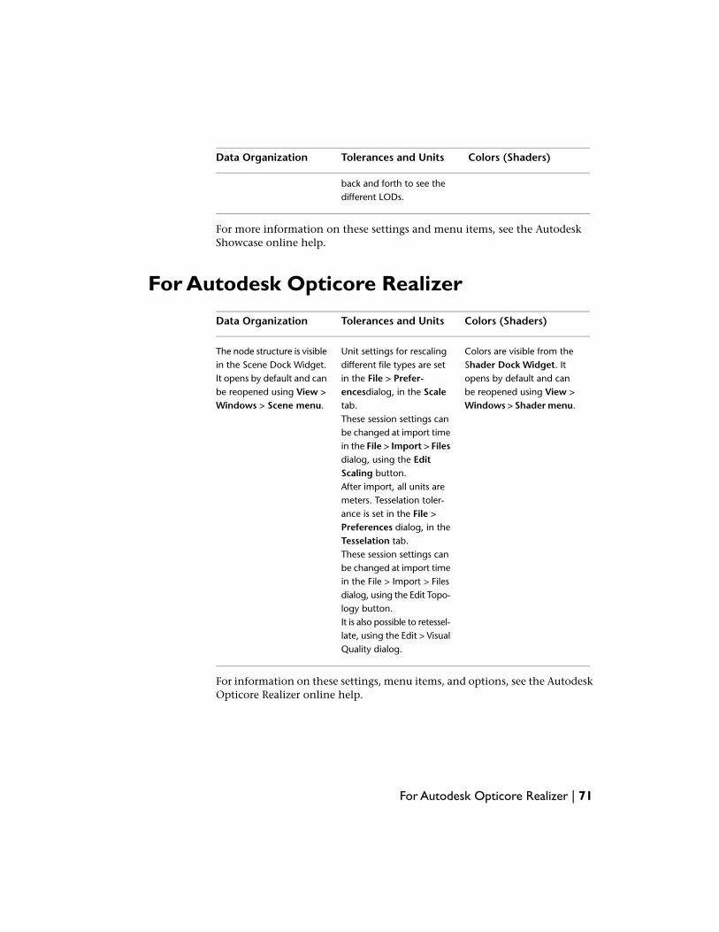
For Autodesk Opticore Realizer
Colors (Shaders)Tolerances and UnitsData Organization
Colors are visible from theShader Dock Widget. It
Unit settings for rescalingdifferent file types are set
The node structure is visiblein the Scene Dock Widget.
opens by default and canin the File > Prefer-It opens by default and canbe reopened using View >Windows > Shader menu.
encesdialog, in the Scaletab.
be reopened using View >Windows > Scene menu.
These session settings canbe changed at import timein the File > Import > Filesdialog, using the EditScaling button.After import, all units aremeters. Tesselation toler-ance is set in the File >Preferences dialog, in theTesselation tab.These session settings canbe changed at import timein the File > Import > Filesdialog, using the Edit Topo-logy button.It is also possible to retessel-late, using the Edit > VisualQuality dialog.
For information on these settings, menu items, and options, see the AutodeskOpticore Realizer online help.
For Autodesk Opticore Realizer | 71
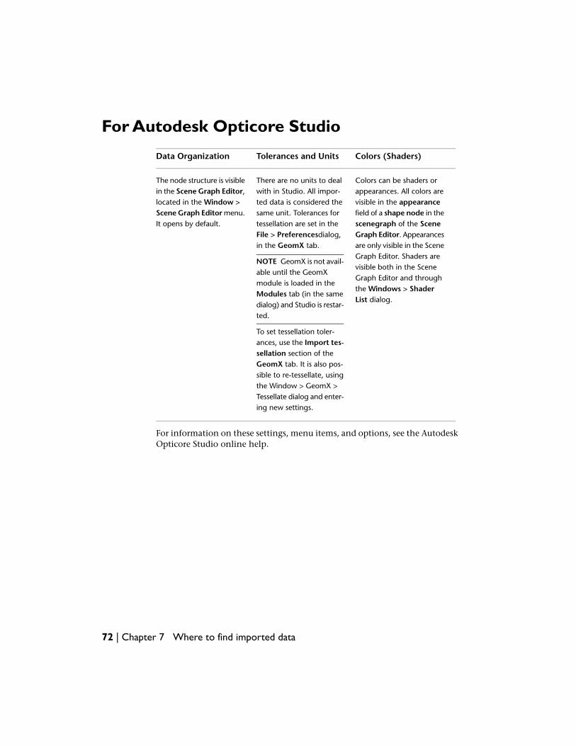
For Autodesk Opticore Studio
Colors (Shaders)Tolerances and UnitsData Organization
Colors can be shaders orappearances. All colors are
There are no units to dealwith in Studio. All impor-
The node structure is visiblein the Scene Graph Editor,
visible in the appearanceted data is considered thelocated in the Window >field of a shape node in thesame unit. Tolerances forScene Graph Editor menu.
It opens by default. scenegraph of the Scenetessellation are set in theGraph Editor. AppearancesFile > Preferencesdialog,
in the GeomX tab.
NOTE GeomX is not avail-able until the GeomXmodule is loaded in theModules tab (in the samedialog) and Studio is restar-ted.
are only visible in the SceneGraph Editor. Shaders arevisible both in the SceneGraph Editor and throughthe Windows > ShaderList dialog.
To set tessellation toler-ances, use the Import tes-sellation section of theGeomX tab. It is also pos-sible to re-tessellate, usingthe Window > GeomX >Tessellate dialog and enter-ing new settings.
For information on these settings, menu items, and options, see the AutodeskOpticore Studio online help.
72 | Chapter 7 Where to find imported data
Glossary
assembly An organizational file that fits together a collection of manufactured parts into acomplete model.
CATIA® V4 CATIA V4 is computer-aided design software from Dassault Systèmes. AutodeskDirectConnect allows the exchange of 3D model data from CATIA V4, using .model, .session,
.exp, .dlv, and .dlv3 files.
CATIA® V5 CATIA V5 is computer-aided design software from Dassault Systèmes. AutodeskDirectConnect allows the exchange of 3D model data from CATIA V5, using the native CATIApart (.CATPart) and product (.CATProduct) files.
Cosmo™ A legacy 3D file format from Silicon Graphics Inc. using efficient binary compressionand *.csb (Cosmo Scene Binary) files.
DRAW (DR) A two-dimensional entity defined in the drafting and detailing world.
DWG AutoCAD drawing file) A file format used by Autodesk® AutoCAD® software thatcontains lines, curves, and 3D data.
DXF (Drawing eXchange File) A file exchange format containing ASCII code and binaryrepresentations of the objects in a DWG file.
Granite® One A CAD technology platform for design collaboration using solid models.
IGES (Initial Graphics Exchange Specification) A file format for transferring graphics databetween CAD/CAM systems. A neutral file format that can be imported into any number ofCAD or modeling packages.
Inventor (Open Inventor™) Open Inventor™ is a legacy 3D file format from SiliconGraphicsInc. With no relation to Autodesk Inventor® software. OpenInventor is an object-oriented3D toolkit that describes complete 3D scenes which can be made interactive and that areoptimized for OpenGL. It is an ASCII or binary file format.
JT file The DirectModel format JT is developed and supported by the JT Open Program. It isa format for the visualization of 3D models.
8
73

parts Parts are organized into a collection of groups, which then forms a project hierarchy.
Pro/ENGINEER® A product from Parametric Technology Corporation. A solid modelingCAD/CAM/CAE software that requires positional construction tolerances.
SolidWorks® A product from SolidWorks Corporation. A solid modeling CAD/CAM/CAEsoftware that requires positional construction tolerances.
SPACE (SP) A three-dimensional entity defined in the 3D modeling world.
STEP An international standard for the exchange of geometric product definitions. STEPformats that are relevant to Autodesk products are AP203 (general mechanical CAD) andAP214 (automotive CAD).
STL An STL ("StereoLithography") file is a triangular representation of 3D surface geometry.The surface is tessellated or broken down logically into a series of small triangles (facets).Each facet is described by a perpendicular direction and three points representing the vertices(corners) of the triangle.
V3Rx A file format generated by an older versions of CATIA, before CATIA V4.
74 | Chapter 8 Glossary

PCRE and BSD Licenses
PCRE LicensePCRE (Perl-compatible regular expressions) is a library of functions to supportregular expressions whose syntax and semantics are as close as possible to thoseof the Perl 5 language.
Release 7 of PCRE is distributed under the terms of the "BSD" licence, as specifiedbelow. The documentation for PCRE, supplied in the "doc" directory, isdistributed under the same terms as the software itself.
The basic library functions are written in C and are freestanding. Also includedin the distribution is a set of C++ wrapper functions.
The Basic library functions
Written by: Philip Hazel
Email local part: ph10
Email domain: cam.ac.uk
University of Cambridge Computing Service, Cambridge, England.
Copyright (c) 1997-2008 University of Cambridge
All rights reserved.
The C++ wrapper functions
Contributed by: Google Inc.
Copyright (c) 2007-2008, Google Inc.
9
75
All rights reserved.
The BSD (Berkeley Software Distribution)license
Redistribution and use in source and binary forms, with or withoutmodification, are permitted provided that the following conditions are met:
■ Redistributions of source code must retain the above copyright notice, thislist of conditions and the following disclaimer.
■ Redistributions in binary form must reproduce the above copyright notice,this list of conditions and the following disclaimer in the documentationand/or other materials provided with the distribution.
■ Neither the name of the University of Cambridge nor the name of GoogleInc. nor the names of their contributors may be used to endorse or promoteproducts derived from this software without specific prior writtenpermission.
THIS SOFTWARE IS PROVIDED BY THE COPYRIGHT HOLDERS ANDCONTRIBUTORS "AS IS" AND ANY EXPRESS OR IMPLIED WARRANTIES,INCLUDING, BUT NOT LIMITED TO, THE IMPLIED WARRANTIES OFMERCHANTABILITY AND FITNESS FOR A PARTICULAR PURPOSE AREDISCLAIMED. IN NO EVENT SHALL THE COPYRIGHT OWNER ORCONTRIBUTORS BE LIABLE FOR ANY DIRECT, INDIRECT, INCIDENTAL,SPECIAL, EXEMPLARY, OR CONSEQUENTIAL DAMAGES (INCLUDING, BUTNOT LIMITED TO, PROCUREMENT OF SUBSTITUTE GOODS OR SERVICES;LOSS OF USE, DATA, OR PROFITS; OR BUSINESS INTERRUPTION) HOWEVERCAUSED AND ON ANY THEORY OF LIABILITY, WHETHER IN CONTRACT,STRICT LIABILITY, OR TORT (INCLUDING NEGLIGENCE OR OTHERWISE)ARISING IN ANY WAY OUT OF THE USE OF THIS SOFTWARE, EVEN IFADVISED OF THE POSSIBILITY OF SUCH DAMAGE.
76 | Chapter 9 PCRE and BSD Licenses
Legal Notice
Trademarks© 2008 Autodesk, Inc. All Rights Reserved. Except as otherwise permitted byAutodesk, Inc., this publication, or parts thereof, may not be reproduced in anyform, by any method, for any purpose.
Certain materials included in this publication are reprinted with the permissionof the copyright holder.
Trademarks
The following are registered trademarks or trademarks of Autodesk, Inc., in theUSA and/or other countries: 3DEC (design/logo), 3December, 3December.com,3ds Max, ADI, Alias, Alias (swirl design/logo), AliasStudio, Alias|Wavefront(design/logo), ATC, AUGI, AutoCAD, AutoCAD Learning Assistance, AutoCADLT, AutoCAD Simulator, AutoCAD SQL Extension, AutoCAD SQL Interface,Autodesk, Autodesk Envision, Autodesk Insight, Autodesk Intent, AutodeskInventor, Autodesk Map, Autodesk MapGuide, Autodesk Streamline, AutoLISP,AutoSnap, AutoSketch, AutoTrack, Backdraft, Built with ObjectARX (logo), Burn,Buzzsaw, CAiCE, Can You Imagine, Character Studio, Cinestream, Civil 3D,Cleaner, Cleaner Central, ClearScale, Colour Warper, Combustion,Communication Specification, Constructware, Content Explorer,Create>what's>Next> (design/logo), Dancing Baby (image), DesignCenter, DesignDoctor, Designer's Toolkit, DesignKids, DesignProf, DesignServer, DesignStudio,Design|Studio (design/logo), Design Web Format, DWF, DWG, DWG (logo),DWG Extreme, DWG TrueConvert, DWG TrueView, DXF, Ecotect, Exposure,Extending the Design Team, FBX, Filmbox, FMDesktop, Freewheel, GDX Driver,Gmax, Green Building Studio, Heads-up Design, Heidi, HumanIK, IDEA Server,i-drop, ImageModeler, iMOUT, Incinerator, Inventor, Inventor LT, Kaydara,
10
77

Kaydara (design/logo), Kynapse, Kynogon, LocationLogic, Lustre, Matchmover,Maya, Mechanical Desktop, MotionBuilder, Movimento, Mudbox, NavisWorks,ObjectARX, ObjectDBX, Open Reality, Opticore, Opticore Opus, PolarSnap,PortfolioWall, Powered with Autodesk Technology, Productstream,ProjectPoint, ProMaterials, RasterDWG, Reactor, RealDWG, Real-time Roto,REALVIZ, Recognize, Render Queue, Retimer,Reveal, Revit, Showcase,ShowMotion, SketchBook, SteeringWheels, Stitcher, StudioTools, Topobase,Toxik, TrustedDWG, ViewCube, Visual, Visual Construction, Visual Drainage,Visual Landscape, Visual Survey, Visual Toolbox, Visual LISP, Voice Reality,Volo, Vtour, Wiretap, and WiretapCentral.
The following are registered trademarks or trademarks of Autodesk CanadaCo. in the USA and/or Canada and other countries: Backburner, Discreet, Fire,Flame, Flint, Frost, Inferno, Multi-Master Editing, River, Smoke, Sparks, Stone,and Wire
The following are registered trademarks or trademarks of Moldflow Corp. inthe USA and/or other countries: Moldflow, MPA, MPA (design/logo), MoldflowPlastics Advisers, MPI, MPI (design/logo), Moldflow Plastics Insight, MPX,MPX (design/logo), Moldflow Plastics Xpert
All other brand names, product names or trademarks belong to their respectiveholders.
Disclaimer
THIS PUBLICATION AND THE INFORMATION CONTAINED HEREIN IS MADEAVAILABLE BY AUTODESK, INC. "AS IS." AUTODESK, INC. DISCLAIMS ALLWARRANTIES, EITHER EXPRESS OR IMPLIED, INCLUDING BUT NOT LIMITEDTO ANY IMPLIED WARRANTIES OF MERCHANTABILITY OR FITNESS FOR APARTICULAR PURPOSE REGARDING THESE MATERIALS.
Government Use
Published by:
Autodesk, Inc.
111 Mclnnis Parkway
San Rafael, CA 94903, USA
78 | Chapter 10 Legal Notice
Index
.asm 51
.csb 47
.g 51
.iam 36
.ipt 36
.iv 47
.prt 51
.sldasm 54
.sldprt 54
.spt 56
.STEP 56
A
assembly 73Autodesk AliasStudio 4, 19
supported translators 4web site 19
Autodesk AutoCAD drawing files 39Autodesk DirectConnect 4, 22, 27
installing 22licensing 27supported platforms 22supported translators 4
Autodesk Inventor 36translator 36
Autodesk Maya 4, 19, 23additional setup 23supported translators 4web site 19
Autodesk Showcase 4, 19supported translators 4web site 19
Autodesk SketchBook home page 1
B
Basic, library 75BSD 75
C
CATIA V4, definition 73CATIA V4, DRAW (DR) 73CATIA V4, SPACE 74CATIA V5 30–31, 33–34
import 31, 34translator 30, 33
CATIA V5, definition 73Cosmo 47
itranslator 47Cosmo, definition 73
D
data, where to find after import 69, 71–72
DR, definition 73DRAW, definition 73Drawing eXchange File 39DWG DXF 39
translator 39DWG, definition 73DXF, definition 73
F
file format 47.csb 47.iv 47
file formats 36.iam 36.ipt 36
files, import 27formats, summary 4
G
glossary 73
79 | Index
Granite One, definition 73
I
IGES 41translator 41
IGES, definition 73Import 31, 34
CATIA V5 31, 34import files 28imported data, where to find 69, 71–72Initial Graphics Exchange
Specification 41installing Autodesk DirectConnect 27installing host software 21Inventor (Open Inventor), definition 73
J
JT 49translator 49
JT, definition 73
L
license 4, 27purchase and install 27when required 4
license, BSD 75license, PCRE 75
M
Mac OS X platform 42, 57supported formats 42, 57
O
Open Inventor 47translator 47
organization of imported data 69, 71–72
P
parts, definition 74PCRE 75plug-in, Maya 23Pro/ENGINEER 51
translator 51Pro/ENGINEER, definition 74
S
shaders, where to find 69, 71–72SolidWorks 54
translator 54SolidWorks, definition 74SP, definition 74SPACE, definition 74STEP 56
translator 56STEP, definition 74STL 59
translator 59STL, definition 74summary, support formats 4support platforms 22system requirements 22
T
tolerances of imported data 69, 71–72translator 36, 39, 41, 47, 49, 51, 54, 56,
59–60Autodesk Inventor 36Cosmo 47DWG DXF 39IGES 41JT 49Open Inventor 47Pro/ENGINEER 51SolidWorks 54STEP 56STL 59UGS NX 60
troubleshooting 28, 43Autodesk AliasStudio import
options 43
80 | Index
can’t see CAD file to import 28
U
UGS NX 60translator 60
units of imported data 69, 71–72
V
V3Rx, definition 74
W
where to find imported data 69, 71–72Windows platform 22
Index | 81

82