Embed Size (px)
Citation preview
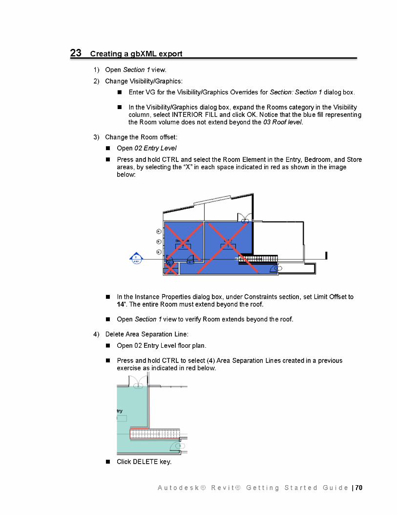
Autodesk® Revit® Getting Started Guide
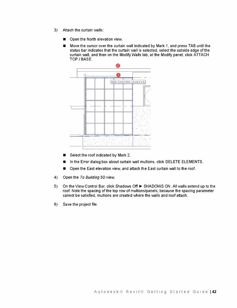
Autodesk® Revit® Getting Started Guide 11
Disclaimer A AUTODESK.
THIS PUBLICATION AND THE INFORMATION CONTAINED HEREIN IS MADE AVAILABLE BY AUTODESK, INC. "AS IS." AUTODESK, INC. DISCLAIMS ALL WARRANTIES, EITHER EXPRESS OR IMPLIED, INCLUDING BUT NOT LIMITED TO ANY IMPLIED WARRANTIES OF MERCHANTABILITY OR FITNESS FOR A PARTICULAR PURPOSE REGARDING THESE MATERIALS.
Trademarks
Autodesk, AutoCAD, DWG, and Revit are registered trademarks or trademarks of Autodesk, Inc., and/or its subsidiaries and/or affiliates in the USA and/or other countries. All other brand names, product names, or trademarks belong to their respective holders. Autodesk reserves the right to alter product offerings and specifications at any time without notice, and is not responsible for typographical or graphical errors that may appear in this document.
Document Licensing This curriculum is licensed under a Creative Commons Attribution-NonCommercial-ShareAlike 3.0 Unported License.
Please see the Autodesk Creative Commons FAQ for more information.
Introductory Notes
This Autodesk® Revit® Getting Started Guide was written using the 2015 version of this product and uses screen captures from the full Revit application that includes all disciplines (Architecture, Structure, and MEP). Please note that this tutorial may also be used with dedicated versions of Autodesk® Revit® Architecture or earlier versions of Revit going back to release 2012.
Nomenclature used in this tutorial:
Text entry required by user Bold Command, key entry, or button clicks ALL CAPS Selection of named items or elements Italics
Autodesk® Revit® Getting Started Guide 12
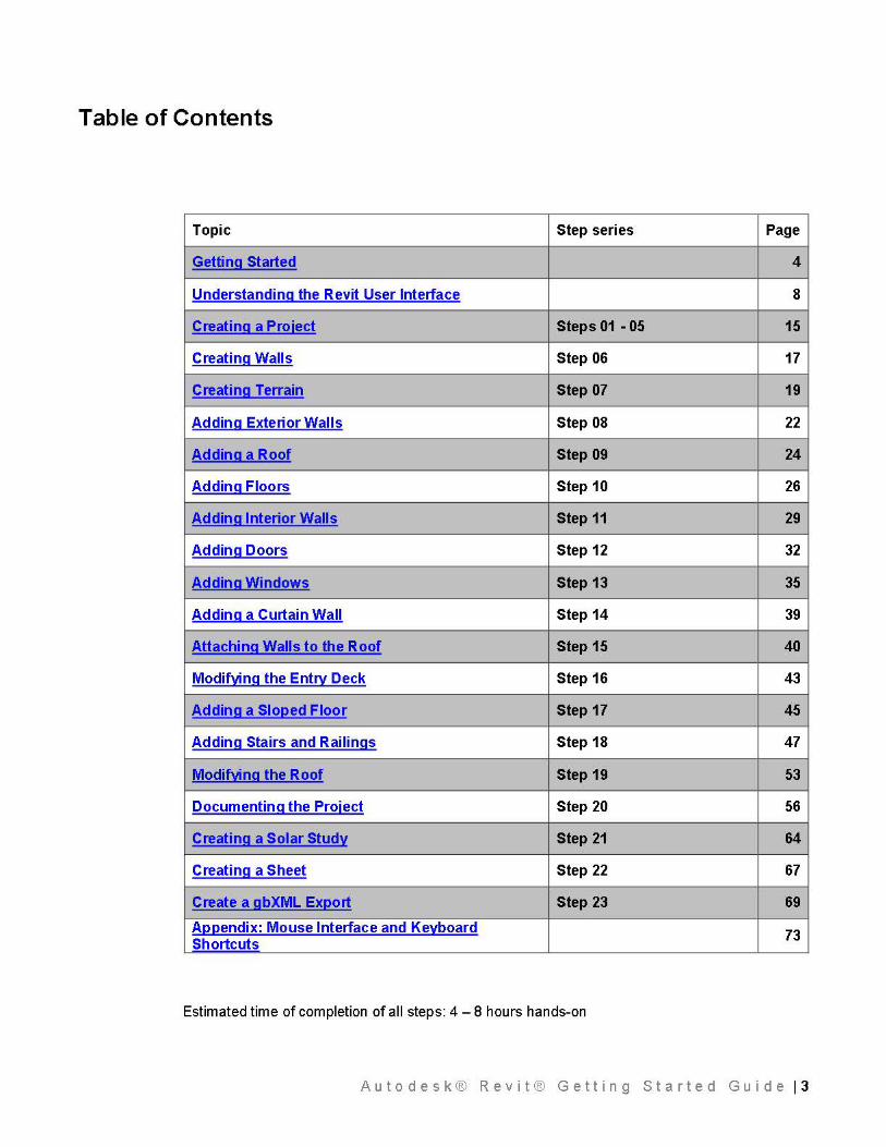
Table of Contents
Topic Step series Page
Getting Started 4
Understanding the Revit User Interface 8
Creating a Project Steps 01 - 05 15
Creating Walls Step 06 17
Creating Terrain Step 07 19
Adding Exterior Walls Step 08 22
Adding a Roof Step 09 24
Adding Floors Step 10 26
Adding Interior Walls Step 11 29
Adding Doors Step 12 32
Adding Windows Step 13 35
Adding a Curtain Wall Step 14 39
Attaching Walls to the Roof Step 15 40
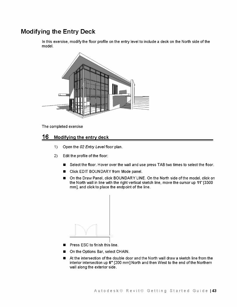
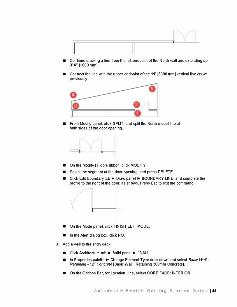
Modif~ng the Entrv Deck Step 16 43
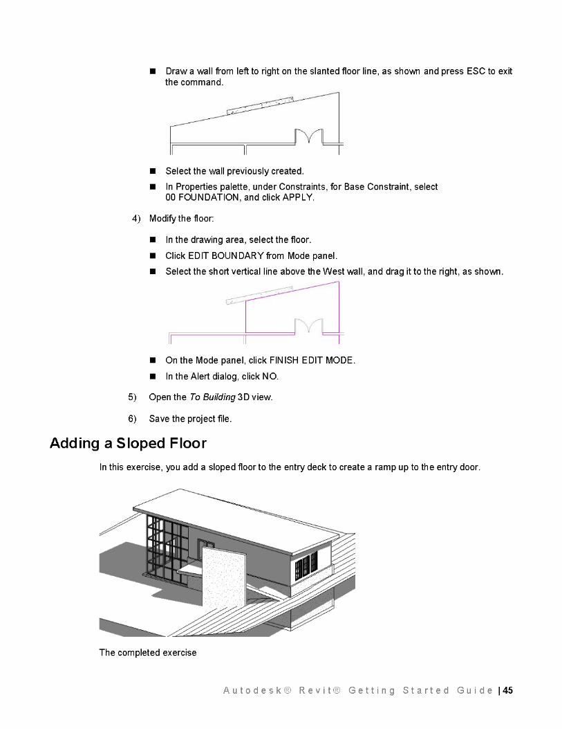
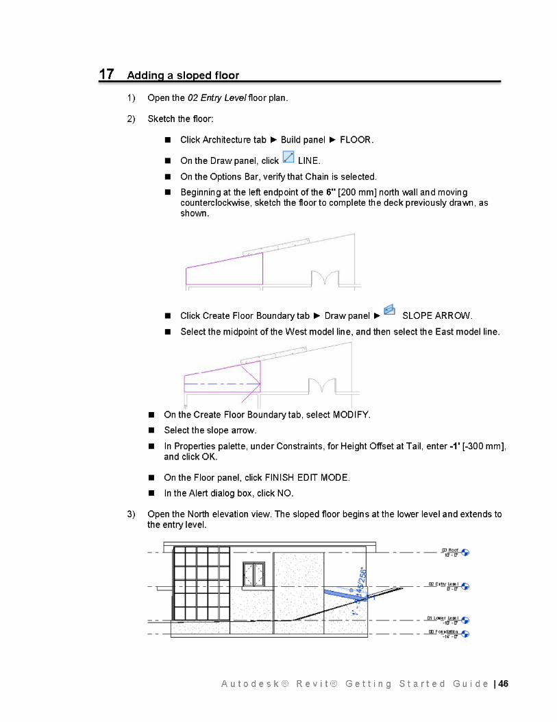
Adding a Slo(!ed Floor Step 17 45
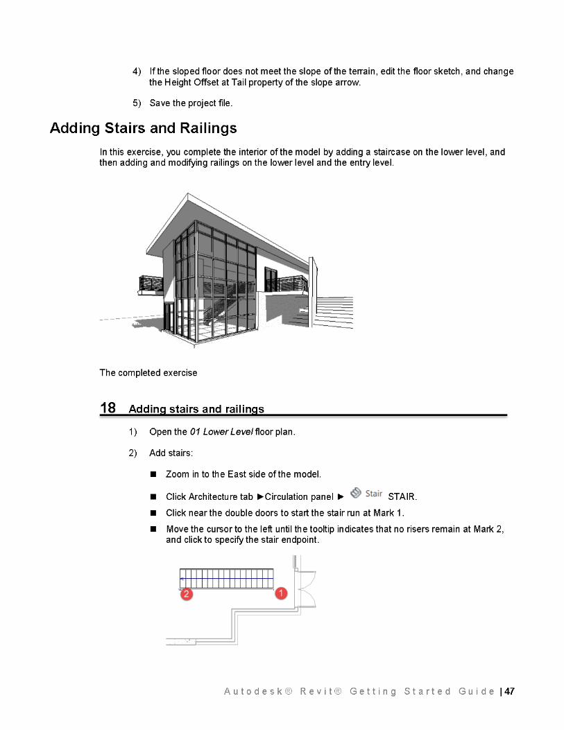
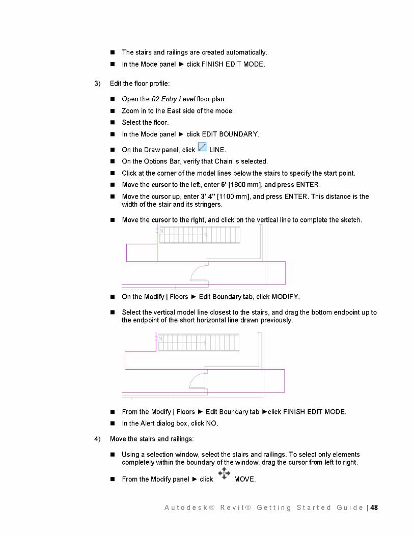
Adding Stairs and Railings Step 18 47
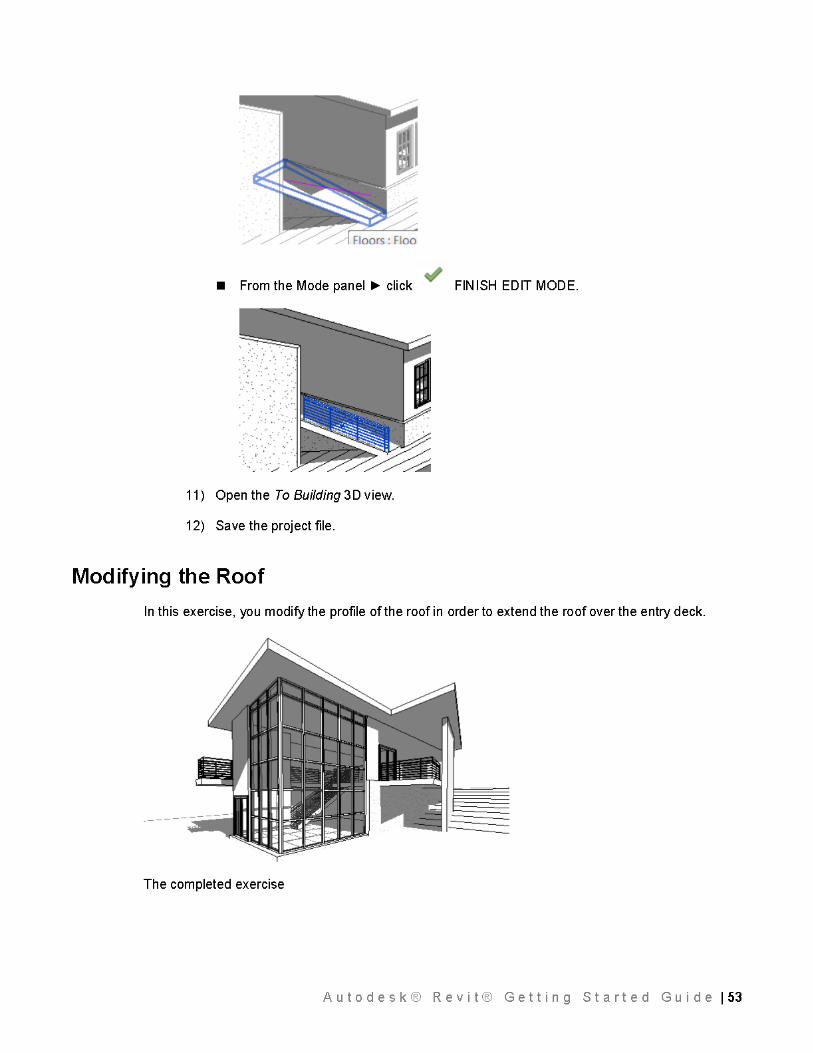
Modif~ng the Roof Step 19 53
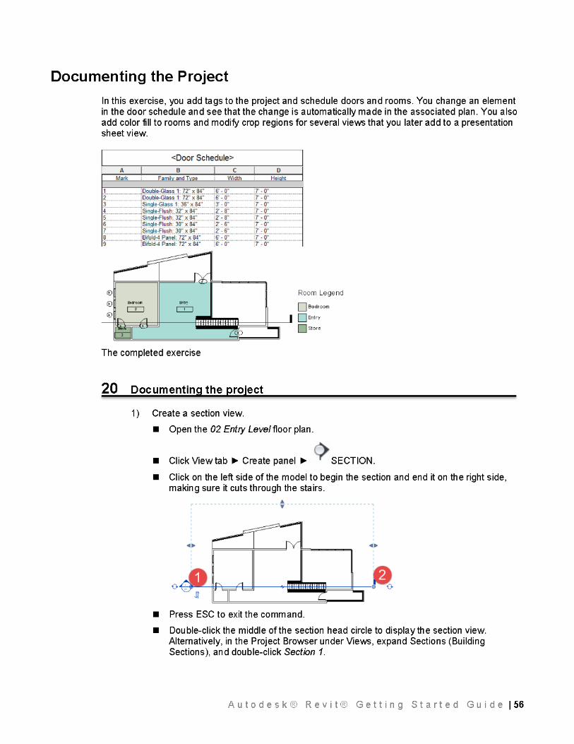
Documenting the Project Step 20 56
Creating a Solar Studl£ Step 21 64
Creating a Sheet Step 22 67
Create a gbXML EX(!Ort Step 23 69
A1rnendix: Mouse Interface and Ke~board 73 Shortcuts
Estimated time of completion of all steps: 4 - 8 hours hands-on
Autodesk® Revit® Getting Started Guide 13
Getting Started
Understanding the Basics
In this lesson, you learn what Autodesk Revit is and how its parametric change engine benefits you and your work. You begin \J\lith the fundamental concepts on which Revit is built. You learn the terminology, the hierarchy of elements, and how to perform some common tasks in the product.
Understanding the Concepts
What is Autodesk® Revit® 2015?
The Revit platform for building information modeling is a design and documentation system that supports the design, drawings, and schedules required for a building project. Building information modeling (BIM) delivers information about project design, scope, quantities, and phases when you need it.
In the Revit model, every dra\J\ling sheet, 20 and 30 view, and schedule is a presentation of information from the same underlying building model database. As you work in dra\J\ling and schedule views, Revit collects information about the building project and coordinates this information across all other representations of the project. The Revit parametric change engine automatically coordinates changes made anywhere-in model views, dra\J\ling sheets, schedules, sections, and plans.
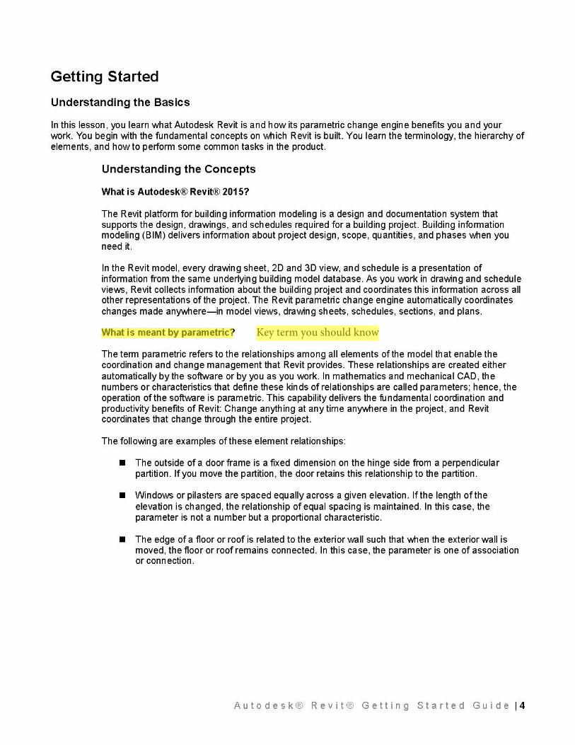
What is meant by parametric?
The term parametric refers to the relationships among all elements of the model that enable the coordination and change management that Revit provides. These relationships are created either automatically by the software or by you as you work. In mathematics and mechanical CAD, the numbers or characteristics th at define these kinds of relationships are called parameters; hence, the operation of the software is parametric. This capability delivers the fundamental coordination and productivity benefits of R evit: Ch an ge anything at any time anywhere in the project, and R evit coordinates that change through the entire project.
The follo\J\ling are examples of these element relationships:
• The outside of a door frame is a fixed dimension on the hinge side from a perpendicular partition. If you move the partition, the door retains this relationship to the partition.
• Windows or pilasters are spaced equally across a given elevation. If the length of the elevation is changed, the relationship of equal spacing is maintained. In this case, the parameter is not a number but a proportional characteristic.
• The edge of a floor or roof is related to the exterior wall such that when the exterior wall is moved, the floor or roof remains connected. In this case, the parameter is one of association or connection.
Autodesk® Revit® Getting Started Guide 14
Key term you should know
How does Autodesk® Revit® 2015 keep things updated?
A fundamental characteristic of a building information modeling application is the ability to coordinate changes and maintain consistency at all times. You do not have to intervene to update drawings or links. When you change something, Revit immediately determines \J\lhat is affected by the change and reflects that change to any affected elements.
Revit uses 2 key concepts that make it especially powerful and easy to use. The first is the capturing of relationships \J\lhile the designer works. The second is its approach to propagating building changes. The result of these concepts is software that works like you do, without requiring entry of data that is unimportant to your design.
Element behavior in a parametric modeler
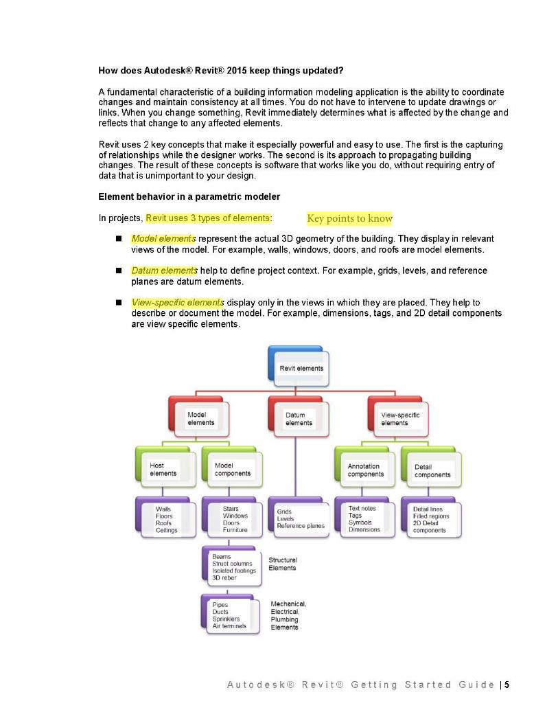
In projects, Revit uses 3 types of elements:
• Model elements represent the actual 30 geometry of the building. They display in relevant views of the model. For example, walls, windows, doors, and roofs are model elements.
• Datum elements help to define project context. For example, grids, levels, and reference planes are datum elements.
• View-specific elements display only in the views in \J\lhich they are placed. They help to describe or document the model. For example, dimensions, tags, and 20 detail components are view specific elements.
Host elements
Walls Floors Roofs Ceilings
Model e lements
Model components
Stairs Windows Doors Furn~ure
Beams Struct columns Isolated footings 30 rebar
I
Pipes Ducts Sprinklers Air terminals
Revit e lements
Datum elements
Grids Levels Reference planes
Structural Elements
Mechanical, Electrical, Plumbing Elements
Annotation
View-specific elements
Deta il components components
Text notes Detail lines Tags Filled regions Symbols 2D Detail Dimensions components
Autodesk® Revit® Getting Started Guide 15
Key points to know
There are 2 types of model elements:
• Hosts (or host elements) are generally built in place at the construction site. For example, walls and roofs are hosts.
• Model components are all the other types of elements in the building model. For example, windows, doors, and cabinets are model components.
There are 2 types of view-specific elements:
• Annotation elements are 20 components that document the model and maintain scale on paper. For example, dimensions, tags, and keynotes are annotation elements.
• Details are 20 items that provide details about the building model in a particular view. Examples include detail lines, filled regions, and 20 detail components.
This implementation provides flexibility for designers. Revit elements are designed to be created and modified by you directly; programming is not required. If you can draw, you can define new parametric elements in Revit.
In Revit, the elements determine their behavior largely from their context in the building. The context is determined by how you draw the component and the constraint relationships that are established with other components. Often, you do nothing to establish these relationships; they are implied by what you do and how you draw. In other cases, you can explicitly control them, by locking a dimension or aligning 2 walls, for example.
Understanding Autodesk® Revit® 2015 terms
Most of the terms used to identify objects in Revit are common, industry-standard terms familiar to most architects. However, some terms are unique to Revit. Understanding the following terms is crucial to understanding the software.
Project: In Revit, the project is the single database of information for your design-the building information model. The project file contains all information for the building design, from geometry to construction data. This information includes components used to design the model, views of the project, and drawings of the design. By using a single project file, Revit makes it easy for you to alter the design and have changes reflected in all associated areas (plan views, elevation views, section views, schedules, and so forth). Having only one file to track also makes it easier to manage the project.
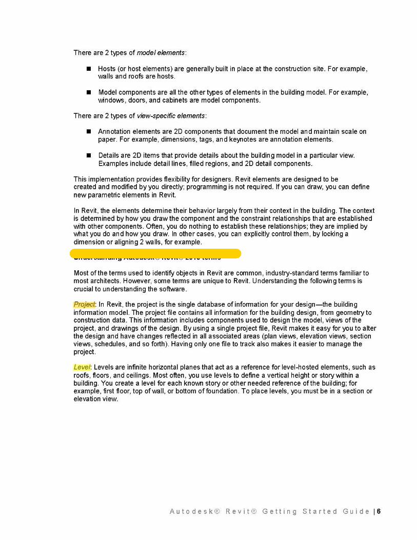
Level: Levels are infinite horizontal planes that act as a reference for level-hosted elements, such as roofs, floors, and ceilings. Most often, you use levels to define a vertical height or story within a building. You create a level for each known story or other needed reference of the building; for example, first floor, top of wall, or bottom of foundation. To place levels, you must be in a section or elevation view.
Autodesk® Revit® Getting Started Guide 16
-----
D
Level 2 work plane cutting through the 30 view with the corresponding floor plan next to it
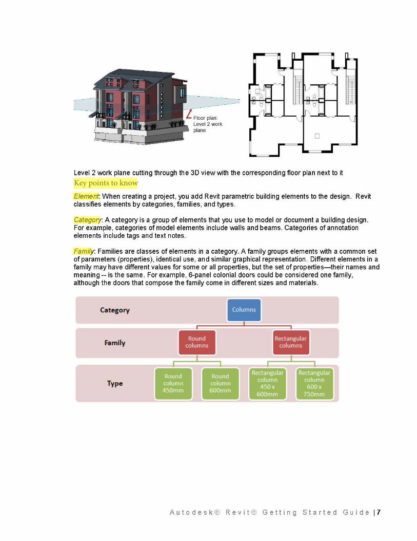
Element: When creating a project, you add Revit parametric building elements to the design. Revit classifies elements by categories, families, and types.
Category: A category is a group of elements that you use to model or document a building design. For example, categories of model elements include walls and beams. Categories of annotation elements include tags and text notes.
Family: Families are classes of elements in a category. A family groups elements with a common set of parameters (properties), identical use, and similar graphical representation. Different elements in a family may have different values for some or all properties, but the set of properties-their names and meaning-- is the same. For example, 6-panel colonial doors could be considered one family, although the doors that compose the family come in different sizes and materials.
Category
I I
Family •• ~~~~~~~~~~~~~~1~~~~~~~~~~-f·~~~~~
~~~~~~~~~;:::::::::::::J~~~~~l•~~~~~~~~~~~~~l-~~--
Type ••••
Autodesk® Revit® Getting Started Guide 17
Key points to know
There are 3 kinds of families:
• Loadable families can be loaded into a project and created from family templates. You can determine the set of properties and the graphical representation of the family.
• System families include walls, dimensions, ceilings, roofs, floors, and levels. They are not available for loading or creating as separate files.
• Revit predefines the set of properties and the graphical representation of system families.
• You can use the predefined types to generate new types that belong to this family within the project. For example, the behavior of a wall is predefined in the system. However, you can create different types of walls with different compositions.
• System families can be transferred between projects.
• In-place families are custom families that you create in the context of a project. Create an in-place family when your project needs unique geometry that you do not expect to reuse or geometry that mu st maintain one of more relationships to other project geometry.
• Because in-place families are intended for limited use in a project, each in-place family contains only a single type. You can create multiple in-place families in your projects, and you can place copies of the same in-place family element in your projects. Unlike system and standard component families, you cannot duplicate in-place family types to create multiple types.
Type: Each family can have several types. A type can be a specific size of a family, such as a 30" X 42" title block or a 32" x 84" door. A type can also be a style, such as default aligned or default angular style for dimensions.
Instance: Instances are the actual items (individual elements) that are placed in the project and have specific locations in the building (model instances) or on a drawing sheet (annotation instances).
Understanding the Revit User Interface
Rev it is a powerful CAD product for the Microsoft® Windows operating system. Its interface resembles those of other products for Windows featuring a ribbon that contains the tools used to complete tasks.
In the Revit interface, many of the components (such as walls, beams, and columns) are available at the click ofa button. You can place these components in the drawing and immediately determine whether they meet your design requirements.
The Revit interface is designed to simplify your workflow. With a few clicks, you can change the interface to better support the way that you work. For example, you can set the ribbon to one of the three display settings for optimum use of the interface. You can also display several project views at one time, or layer the views to see only the one on top.
Autodesk® Revit® Getting Started Guide 18
'"""""""' - --c::J [J cv. . .- 1i1Roo1 - llii) c...-~ w.1 Doo• E!J Co-• · ~ c .. "'9 f!l ,..,._ Gnd
Column • Roof •
c::J [J Cw . .- 1i1Roo1 - lij) c ...... ~ .... IJ~ - ;::, 0oot E!J c......- . ,,_ '"'"'9 f!l '"""" Gnd C> 1totnp II..
oc.-... S F- · !fi '-'<... ~S...· · ~ -
W•s(I)
Con:su•nts * ~ lQC.C:IOnllM (W.i•Gtnttrllnc: 8Me (onJCtWlt l~tl l .... Off1CI ·1500.0
~· J---11 • ~ ""• n~(rtf'P"'1 <)'"I o.O
1 2 3 4 5 6 7 8 9
TopConw""' U,,lO .... •tl-
"
fromVttd ICit(heft
lMtogS..bonPcnpc<Wc
w..~ 1)01
w,
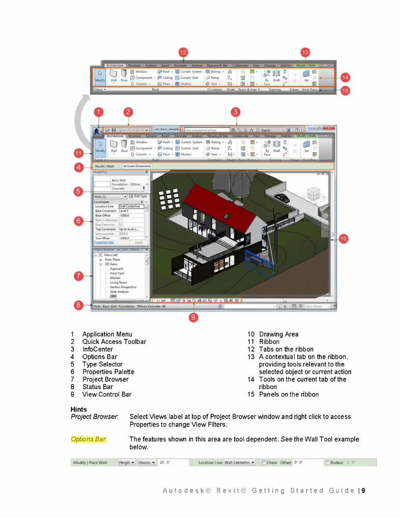
Application Menu Quick Access Toolbar lnfoCenter Options Bar Type Selector Properties Palette Project Browser Status Bar View Control Bar
10 Drawing Area 11 Ribbon 12 Tabs on the ribbon 13 A contextual tab on the ribbon,
providing tools relevant to the selected object or current action
14 Tools on the current tab of the ribbon
15 Panels on the ribbon
Hints Project Browser.
Options Bar.
Modify I Place Wall
Select Views label at top of Project Browser window and right click to access Properties to change View Filters.
The features sho\J\111 in this area are tool dependent. See the Wall Tool example below.
Heigh • Uncon • 20" o· Location Line: Wall Centerlin • D Chain Offset: o· o· ;:] Radius: r o·
Autodesk® Revit® Getting Started Guide 19
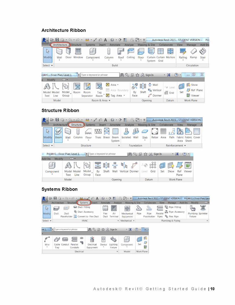
Architecture Ribbon
Modify Wall Door Window Component Column Roof Ceiling Floor Curtain Curtain Mullion Railing Ramp Stair System Grid
Select • Build Circulation
loo ~ ~ -tr .,Q, Sign In
IA) l \_ [CO] ~ ~ ~ [81 Area • "p
Model Model Model Room Room Tag Text Line Group Separator Room • ~ Tag Area
~* ~Wall ~ [ii'~ Show
By Shaft lll!, Vertical
!S Grid Set [} Ref Plane
Face r Dormer rm Viewer
Model Room & Area • Opening Datum Work Plane
Structure Ribbon
~ A Autodesk Revit 2015 • STUDENT VERSION 1 Insert Annotate & Site Collaborate View Mana
Column Floor Truss Brace Beam Isolated Wall Slab Rebar Area Path Fabric Fabric Cover Area Sheet System
Select • Structure Foundation Reinforcement •
llffi ~ i} 1'.4 .!::!:. Sign In
~ ]\_ [CO] l..:J ......... n
Component Model Model Model By Shaft Wall Vertical Dormer Grid Set Show Ref Viewer Plane Text line Group Face
Model Opening Datum Work Plane
Systems Ribbon
~ . io B · ~ ·..,...~ ..... Autodesk Revit 2015 · STUDENT VERSION · Projectl · Floor Plan: Lev
Architecture Structu Insert
6JD D ~ Duct Accessory uct uct
Placeholder ]) Conven to Flex Duct
Select • HVAC
r ~ tiiij Wliiii Q ~ Elllliiii .. . ~
Wire Cable Conduit Parallel Electrical Tray Conduits Equipment
Electrical
Flex Air Duct Terminal
Mechanical Equipment
& Site Collaborate View Mana e Add· lns Modi
Pipe
(=:; ClJ Pipe Fining c::::;
Pipe Parallel .'lit Pipe Accessory
Placeholder Pipes '110 Flex Pipe
~:I:
v Mechanical :w Plumbing & Piping
Plumbing Sprinkler I Fixture .
. ~ cv ·n
~ ~ 0 ~ rt. [} Device lighting Component Set
Fixture ~ Model Work Plane
Autodesk® Revit® Getting Started Guide 110
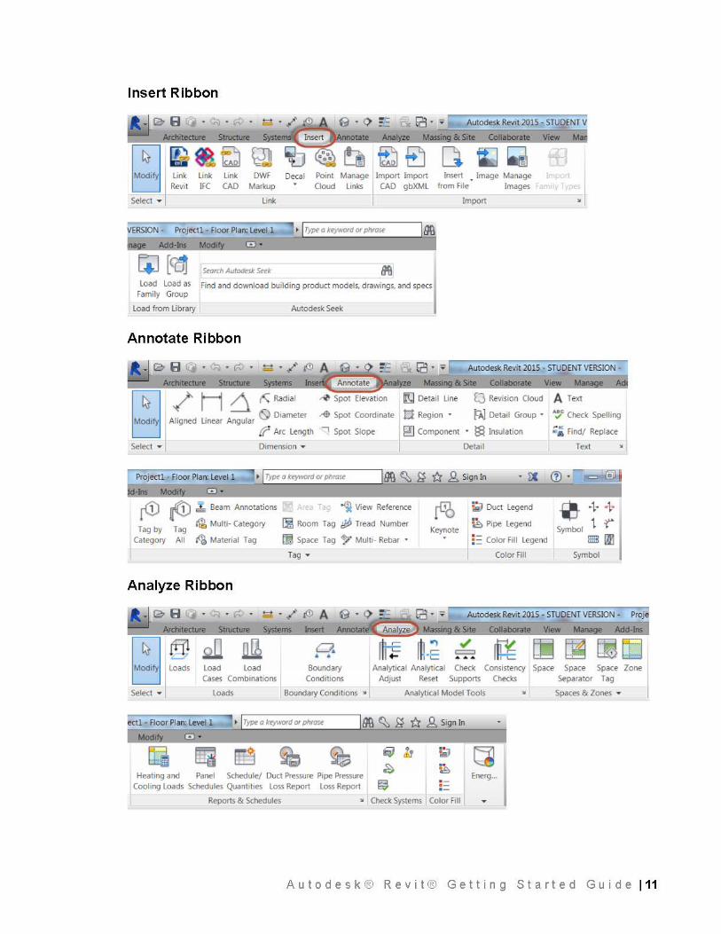
Insert Ribbon
~ro B r · '""' Autodesk Revit 2015 - STUDENT V Architecture Structure S em
~ !!~~Decal l:::j Revit IFC CAO Markup Point Cloud
Manage Import Import
links I CAO gbXML
Select • Link
VERSION - Project! - floor Plan: Level 1 .:.=-• .LI T_ype~o_k_eywo~-"'-o_r_p11_r_o_re~~---'IOO e Add-Ins Modi
Storch Autodt!sk St!tk
Load Load as Find and download building product models, drawings, and specs Family Group
Load from Library Autodesk Seek
Annotate Ribbon
& Site Collaborate Ma
Insert • Image Manage from file Images
Import
I~ { '° e . "' . "" . ~ . ,/ Autodesk Revit 2015 · STUDENT VERSION -
Architecture Structure & Site Collaborate View Mana e Ad
./ H 6 ~Radial -0 Spot Elevation CJ Revision Cloud A Text
Al igned Linear Angular 0 Diameter
ff Arc Length
~ Spot Coordinate tl Region • PJ.J Detail Group • ·~c Check Spell ing
.,..., Spot Slope
Select • Dimension •
~ Component • ~ Insulation
Detail
Project! - floor Plan: Level 1 1. Type a ktyword or phrost 00 ~ £f ti .Q. Sign In
d-lns Modi 8 •
~ ~ ""' Beam Annotations
T b T ~ Multi- Category
ag y ag Category All ~ Material Tag
Analyze Ribbon
t T ~ 1/: View Reference
~ Room Tag tJjJ Tread Number
@ Space Tag ~ Multi - Rebar •
Tag •
Keynote
r.;J Duct Legend
~ Pipe Legend
: :: Color Fill Legend
Color Fill
o;~ Find/ Replace
Text
0+ + Symbol 1 ~
I llllil m1
Symbol
. .-. ./ !$) A e · <> _,_ rcJ • • I ,,.---... Autodesk Revit 2015 • STUDENT VERSION - ProA
Select •
S ems Insert Annotate Analyze Massi & Site Collaborate View Mana e Add-Ins
Load Combinations
Loads
a • •
Boundary Conditions
Boundary Conditions •
./ = ... Analytical Analytical Ched< Consistency I Space Space Space Zone
Adjust Reset Supports Checks Separator Tag
Analytical Model Tools • Spaces & Zones •
bctl • f loor Plan: Level 1 ' • I Type a ktyword or phrost loo ~ £f ti .Q. Sign In
Modi
IT] Lid ~ ~ e h ~ ~ ~ ~
Heating and Panel Schedule/ Duct Pressure Pipe Pressure Energ ... Cooling Loads Schedules Quantities Loss Report Loss Report ~ ==
Reports & Schedules • Ched< Systems Color Fill
Autodesk® Revit® Getting Started Guide 111
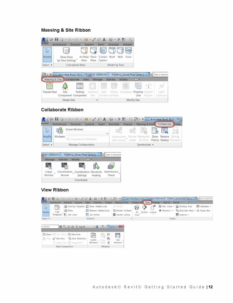
Massing & Site Ribbon
1 .::.~ 0 (JJ ~ Show Mass In-Place Place
by View Settings .
Mass Mass
Select • Conceptual Mass
Toposurface Site Parking Component Component ad
~(J~~ Curtain Roof Wall Floor System
Model by Face
Property Line
~ Type a keywor
(
Model Site Modify Site
Collaborate Ribbon
.. ·~ io B r · "" · "" · ~ · / ' i0 A G · ~ :-.: Architecture Structure S ems Insert
~ ~ Active Worlcset:
t:'J w,.:!, Select • Manage Collaboration
p ENT VERSION - Projectl - Floor Plan: Level 1 h Type a kt!yword
Mana e Add-Ins Modi
Copy/ Monitor
Coordination Coordination Reconcile Interference Review Settings Hosting Check
Coordinate
View Ribbon
Arcllitectur Struct ms lnse
Q :!'iil Visibility/ Graphics ~ Show Hidden Lines
View :t4 Filters lb] Remove Hidden lines
Templates .. ~E Thin Lines [!9 Cut Profile
Select • Grnph1cs
~•o_'""-'-°'-• __ _,100 ~ ~ ti .Q. Sign In [
• lX
b Sheet Q Mat<;hlme
r:f' :evisio; " -<jt View Refe<~nce I Sheet Composition
Switch Windows
Windows
g Rende< in Cloud
ii Rende< Gallery
User Intefface
Autodesk Revit 2015 - STUO
Synchronize •
30 Sectt0n Callout View
(Sll Plan Views - EE Schedules -
~ Elevation • ~ DupliC<lte View • of; Scope Box
[;I Legends •
Autodesk® Revit® Getting Started Guide 112
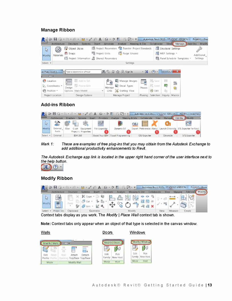
Manage Ribbon
ll'i Project Parameters l"ltl Trans-fer ProJect Standards
Select •
l:.. Coordinates
el Positjon •
ProJect Location
� Project Un,15 Purge Unused
""' Project Information J;I. Shared Parameters
Design
� t '
Options Main Mod�I
Des19n Options
Settings
� Manage Images
M = � Decal Types
anage • Links :g: Starting View
Manage ProJect
Add-ins Ribbon
� ,
External. □ Tools Select • External
Glue
MEP Settings •
t:'a Panel Schedule Templates •
Phases l� Edit
Phasmg Selection Inquiry Macros
Addrt10nal Settings
Mark 1: These are examples of free plug-ins that you may obtain from the Autodesk Exchange to add additional productivity enhancements to Revit.
The Autodesk Exchange app link is located in the upper right hand corner of the user interface next to the help button.
Modify Ribbon
A Architecture Structure S ems lnsert Annotate Anal ze Massi� & Site Collaborate View _M._ana__,,..__.
-- . [tb] [CoJ � � �:� .. ·;. : . � � Q Ql, ;·; � : tj I� I � 0 Join • � I +J+ OQ O ,=-I =' )( I =i • 1 t)J Select • Prope ·1es Chpboard Geometry Modify View Measure Crea e
Context tabs display as you work. The Modify I Place Wall context tab is shown.
Note: Context tabs only appear when an object of that type is selected in the canvas window.
Walls Windows
o.
Edit Edit Pick
��" Pick
Profile Family New Host amily New Host
Mode Mode Host Mode Hos
Aut o d e sk® Re v i t® Ge t t i ng St a r t e d Gui d e 113
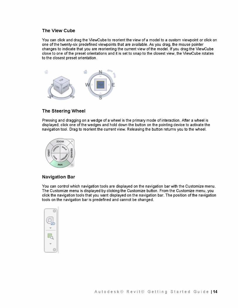
The View Cube
You can click and drag the ViewCube to reorient the view of a model to a custom viewpoint or click on one of the twenty-six predefined viewpoints that are available. As you drag, the mouse pointer changes to indicate that you are reorienting the current view of the model. If you drag the ViewCube close to one of the preset orientations and it is set to snap to the closest view, the ViewCube rotates to the closest preset orientation.
~E s
The Steering Wheel
Pressing and dragging on a wedge of a wheel is the primary mode of interaction. After a wheel is displayed, click one of the wedges and hold down the button on the pointing device to activate the navigation tool. Drag to reorient the current view. Releasing the button returns you to the wheel.
Navigation Bar
You can control which navigation tools are displayed on the navigation bar with the Customize menu. The Customize menu is displayed by clicking the Customize button. From the Customize menu, you click the navigation tools that you want displayed on the navigation bar. The position of the navigation tools on the navigation bar is predefined and cannot be changed .
...
... e
A u t o d e s k ® R e v i t ® G e t t i n g S t a rt e d G u i d e 114
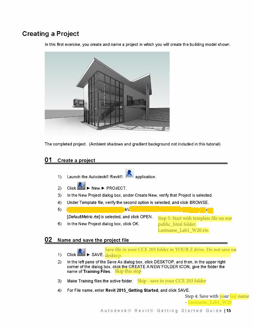
Step 5: Start with template file on our public_html folder:Lastname_Lab1_W20.rte.
Save file in your CCE 203 folder in YOUR Z drive. Do not save on desktop.
Skip - save in your CCE 203 folder
Step 4: Save with your last name - Lastname_Lab1_W20
Skip this step
03 Zoom to a view
1 ) In Project Browser, double-click Elevations (Building Elevation) ~ SOU TH .
2) Enter ZR, to zoom to a specific region. Note that the cursor changes to a magnifying glass.
3) In the drawing area, move the cursor diagonally and click to draw a rectangle around the level markers. The area within the rectangle is magnified to fill the drawing area so that you can work with the level marker text.
___ Le~el~
10' - Q"\J
___ Le~el 1 ~ O' - CT'\J
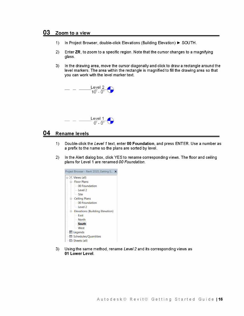
04 Rename levels
1) Double-click the Level 1 text, enter 00 Foundation, and press ENTER. Use a number as a prefix to the name so the plans are sorted by level.
2) In the Alert dialog box, click YES to rename corresponding views. The floor and ceiling plans for Level 1 are renamed 00 Foundation.
Project Browser - Revit 2015_Get1ing S... X
s :o: Views {all)
e Floor Plans
00 Foundation
Level 2
Site
& Ceiling Plans
00 Foundation
Level 2
& Elevations (Building Elevation)
East
North
South
West
la Legends
!El Schedules/Quantities
llii'.l Sheets (all)
3) Using the same method, rename Level 2 and its corresponding views as 01 Lower Level.
Autodesk® Revit® Getting Started Guide 116
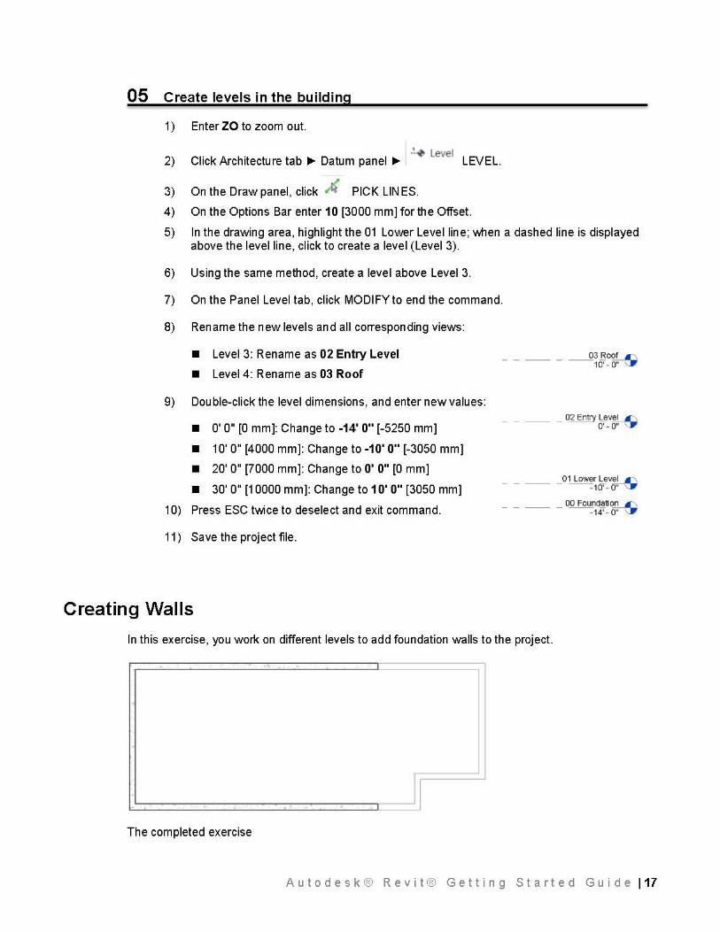
05 Create levels in the building
1) Enter ZO to zoom out.
.!-0 Level Click Architecture tab ~ Datum panel ~ LEVEL.
On the Draw panel, click ~~ PICK LIN ES.
On the Options Bar enter 10 [3000 mm] for the Offset.
2)
3)
4)
5) In the drawing area, highlight the 01 Lower Level line; \J\lhen a dashed line is displayed above the level line, click to create a level (Level 3).
Using the same method, create a level above Level 3. 6)
7)
8)
On the Panel Level tab, click MODIFY to end the command.
Rename the new levels and all corresponding views:
• Level 3: Rename as 02 Entry Level
• Level 4: Rename as 03 Roof
9) Double-click the level dimensions, and enter new values:
• O' O" [O mm]: Change to -14' O" [-5250 mm]
• 10' O" [4000 mm]: Change to -10' O" [-3050 mm]
• 20' O" [7000 mm]: Change to O' O" [O mm]
• 30' O" [10000 mm]: Change to 1 O' O" [3050 mm]
10) Press ESC twice to deselect and exit command.
11) Save the project file.
_ _ __ _ 02 Entry Level I'\ 0'-0"--......
_____ 01 Low~~~v~
_____ 00 Founcl~ti0..!2..._C-,
-14'- 0" \:IP
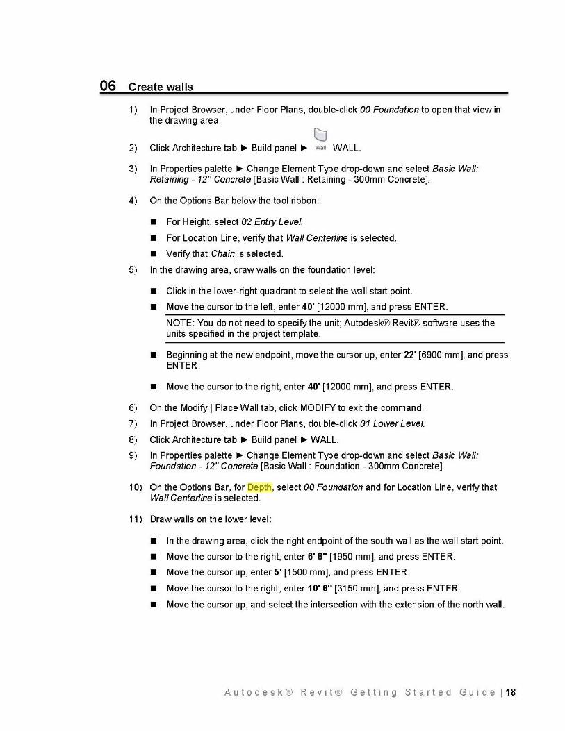
Creating Walls
In this exercise, you work on different levels to add foundation walls to the project.
- .. .
I 1 - -· I
The completed exercise
Autodesk® Revit® Getting Started Guide 117
06 Create walls
1) In Project Browser, under Floor Plans, double-click 00 Foundation to open that view in the drawing area.
CJ 2) Click Architecture tab ~ Build panel ~ wan WALL.
3) In Properties palette ~ Change Element Type drop-down and select Basic Wall: Retaining - 12" Concrete [Basic Wall: Retaining - 300mm Concrete].
4) On the Options Bar below the tool ribbon:
• For Height, select 02 Entry Level.
• For Location Line, verify that Wall Centerline is selected.
• Verify that Chain is selected.
5) In the drawing area, draw walls on the foundation level:
• Click in the lower-right quadrant to select the wall start point.
• Move the cursor to the left, enter 40' [12000 mm], and press ENTER.
NOTE: You do not need to specify the unit; Autodesk® Revit® software uses the units specified in the project template.
• Beginning at the new endpoint, move the cursor up, enter 22' [6900 mm], and press ENTER.
• Move the cursor to the right, enter 40' [12000 mm], and press ENTER.
6) On the Modify I Place Wall tab, click MODIFY to exit the command.
7) In Project Browser, under Floor Plans, double-click 01 Lower Level.
8) Click Architecture tab ~ Build panel ~WALL.
9) In Properties palette ~ Change Element Type drop-down and select Basic Wall: Foundation- 12" Concrete [Basic Wall: Foundation - 300mm Concrete].
10) On the Options Bar, for Depth, select 00 Foundation and for Location Line, verify that Wall Centerline is selected.
11) Draw walls on the lower level:
• In the drawing area, click the right endpoint of the south wall as the wall start point.
• Move the cursor to the right, enter 6' 6" [1950 mm], and press ENTER.
• Move the cursor up, enter 5' [1500 mm], and press ENTER.
• Move the cursor to the right, enter 10' 6" [3150 mm], and press ENTER.
• Move the cursor up, and select the intersection with the extension of the north wall.
Autodesk® Revit® Getting Started Guide 118
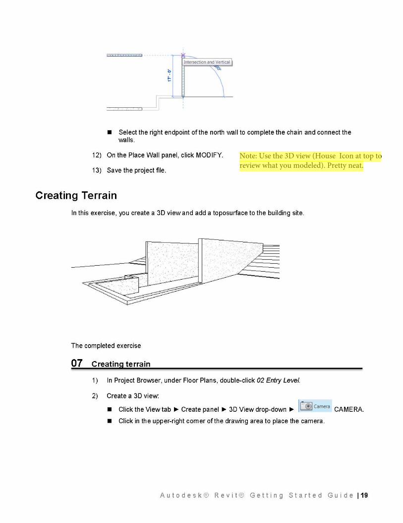
_____ ........ _ - 3
Intersection and Vertical
• Select the right endpoint of the north wall to complete the chain and connect the walls.
12) On the Place Wall panel, click MODIFY.
13) Save the project file.
Creating Terrain
In this exercise, you create a 30 view and add a toposurface to the building site .
. . ,.·
·• .r---- -
The completed exercise
07 Creating terrain
1)
2)
In Project Browser, under Floor Plans, double-click 02 Entry Level.
Create a 30 view:
• Click the View tab~ Create panel~ 30 View drop-down~ II @I camera CAMERA.
• Click in the upper-right comer of the drawing area to place the camera.
Autodesk® Revit® Getting Started Guide 119
Note: Use the 3D view (House Icon at top to review what you modeled). Pretty neat.
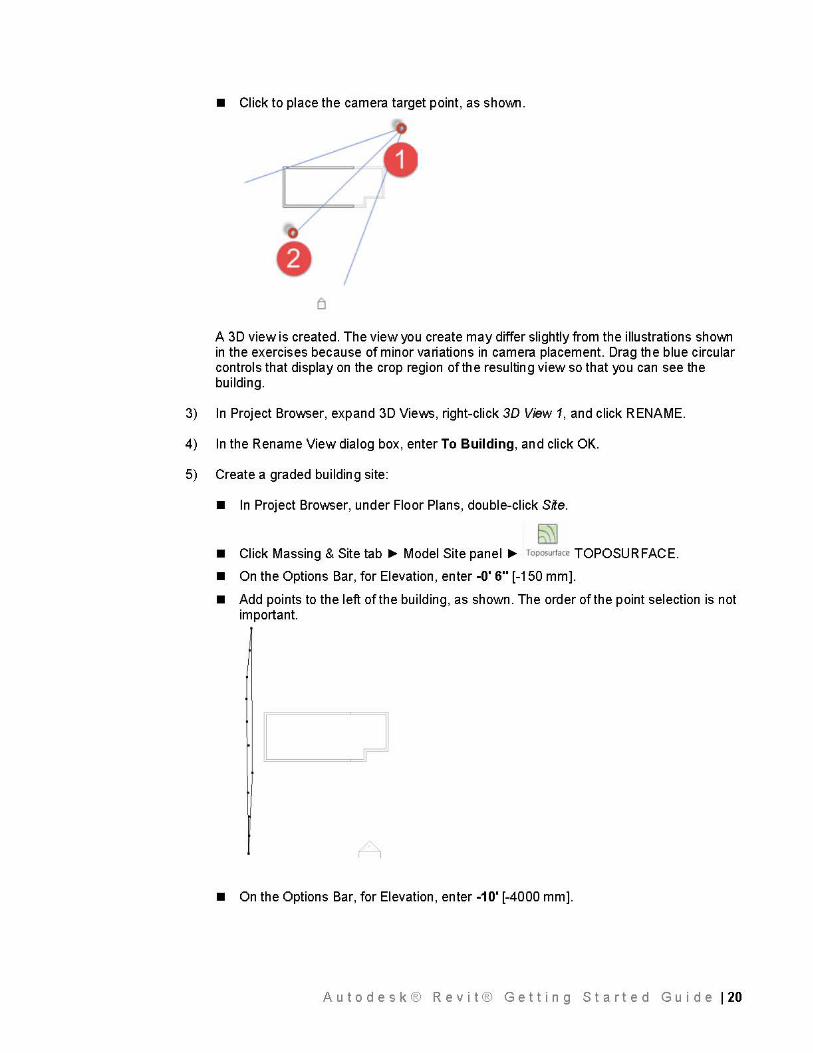
• Click to place the camera target point, as sho\J\111.
A 30 view is created. The view you create may differ slightly from the illustrations sho\J\111 in the exercises because of minor variations in camera placement. Drag the blue circular controls that display on the crop region of the resulting view so that you can see the building.
3) In Project Browser, expand 30 Views, right-click 3D View 1, and click RENAME.
4) In the Rename View dialog box, enter To Building, and click OK.
5) Create a graded building site:
• In Project Browser, under Floor Plans, double-click Site.
~ • Click Massing & Site tab ~ Model Site panel ~ roposurtace TOPOSURFACE.
• On the Options Bar, for Elevation, enter -0' 6" [-150 mm].
• Add points to the left of the building, as shown. The order of the point selection is not important.
• On the Options Bar, for Elevation, enter -10' [-4000 mm].
A u t o d e s k ® R e v i t ® G e t t i n g S t a r t e d G u i d e I 20
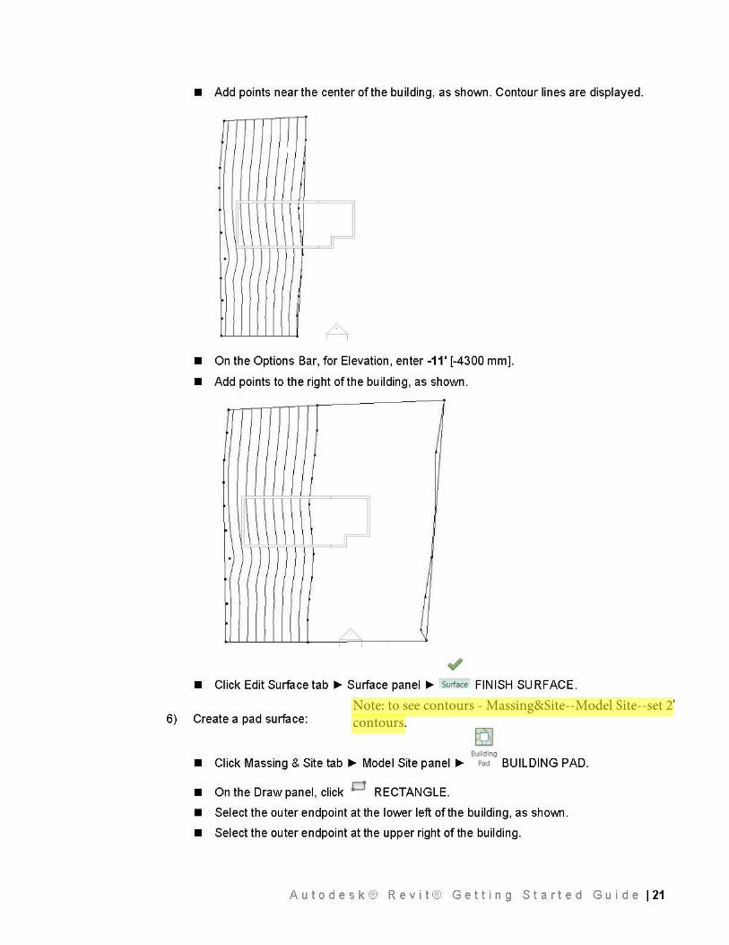
• Add points near the center of the bu ii ding, as shown. Contour lines are displayed.
I I
J I
·I
/-
• On the Options Bar, for Elevation, enter -11' [-4300 mm].
• Add points to the right of the building, as shown.
J
I \ I
~ • Click Edit Surface tab ~ Surface panel ~ surtace FINISH SU RF ACE.
6) Create a pad surface:
Building
• Click Massing & Site tab ~ Model Site panel ~ Pad BUILDING PAD.
• On the Draw panel, click p RECTANGLE.
• Select the outer endpoint at the lower left of the building, as shoWTI.
• Select the outer endpoint at the upper right of the building.
A u t o d e s k ® R e v i t ® G e t t i n g S t a r t e d G u i d e I 21
Note: to see contours - Massing&Site--Model Site--set 2' contours.
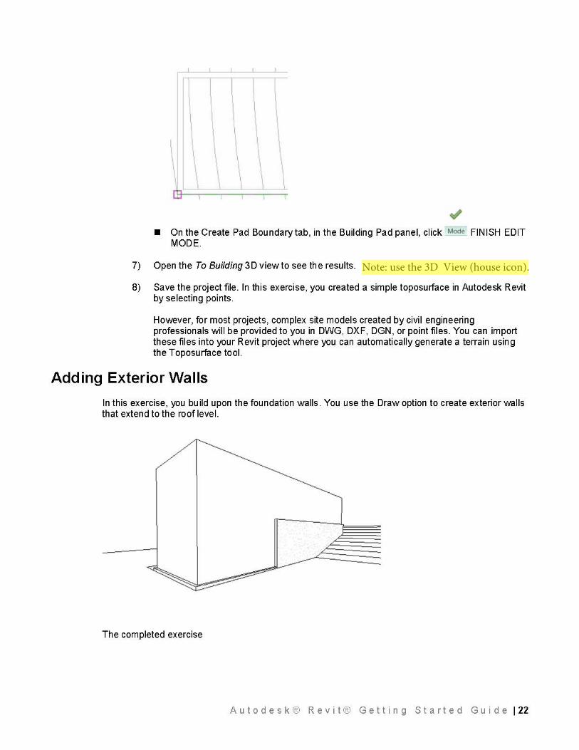
• On the Create Pad Boundary tab, in the Building Pad panel, click Mode FINISH EDIT MODE.
7) Open the To Building 3D view to see the results.
8) Save the project file. In this exercise, you created a simple toposurface in Autodesk Revit by selecting points.
However, for most projects, complex site models created by civil engineering professionals will be provided to you in DWG, DXF, DGN, or point files. You can import these files into your Revit project where you can automatically generate a terrain using the Toposurface tool.
Adding Exterior Walls
In this exercise, you build upon the foundation walls. You use the Draw option to create exterior walls that extend to the roof level.
The completed exercise
A u t o d e s k ® R e v i t ® G e t t i n g S t a r t e d G u i d e I 22
Note: use the 3D View (house icon).
08 Adding exterior walls
1) Add walls to the entry level:
• In Project Browser, under Floor Plans, double-click 02 Entry Level.
• Click Architecture tab ~ Build panel ~WALL.
• In Properties palette ~ Change Element Type drop-down and select Basic Wall: Generic - 6" [Basic Wall : Generic - 200mm].
• On the Options Bar: for Height, select 03 Roof, and for Location Line, select Core Face: Interior.
The Height setting defines how tall the wall is and establishes a relationship between the walls and the roof. After you draw the walls, if you change the roof height, the height of the walls will also change.
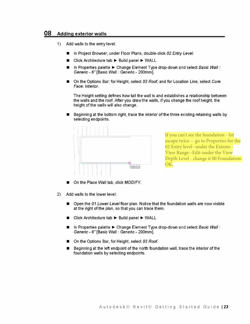
• Beginning at the bottom right, trace the interior of the three existing retaining walls by selecting endpoints.
_J
I I
• On the Place Wall tab, click MODIFY.
2) Add walls to the lower level:
• Open the 01 Lower Leve/floor plan. Notice that the foundation walls are now visible at the right of the plan, so that you can trace them.
• Click Architecture tab ~ Build panel ~WALL
• In Properties palette ~ Change Element Type drop-down and select Basic Wall: Generic - 6" [Basic Wall : Generic - 200mm].
• On the Options Bar, for Height, select 03 Roof.
• Beginning at the left endpoint of the north foundation wall, trace the interior of the foundation walls by selecting endpoints.
A u t o d e s k ® R e v i t ® G e t t i n g S t a r t e d G u i d e I 23
If you can't see the foundation - hit escape twice -- go to Properties for the 02 Entry level--under the Extents - View Range--Edit-under the View Depth Level - change it 00 Foundation-OK.
E9 I Endpoint l
~ ===:::2·:J:I =:::'...i•
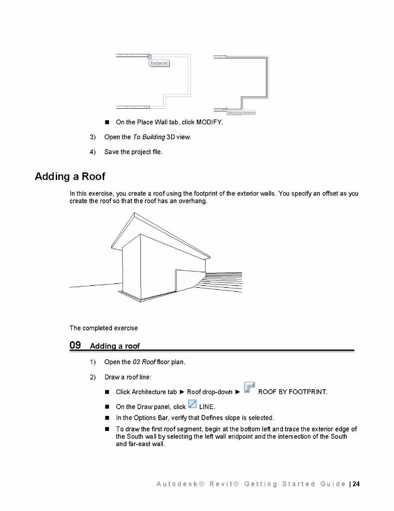
• On the Place Wall tab, click MODIFY.
3) Open the To Building 3D view.
4) Save the project file.
Adding a Roof
In this exercise, you create a roof using the footprint of the exterior walls. You specify an offset as you create the roof so that the roof has an overhang.
The completed exercise
09 Adding a roof
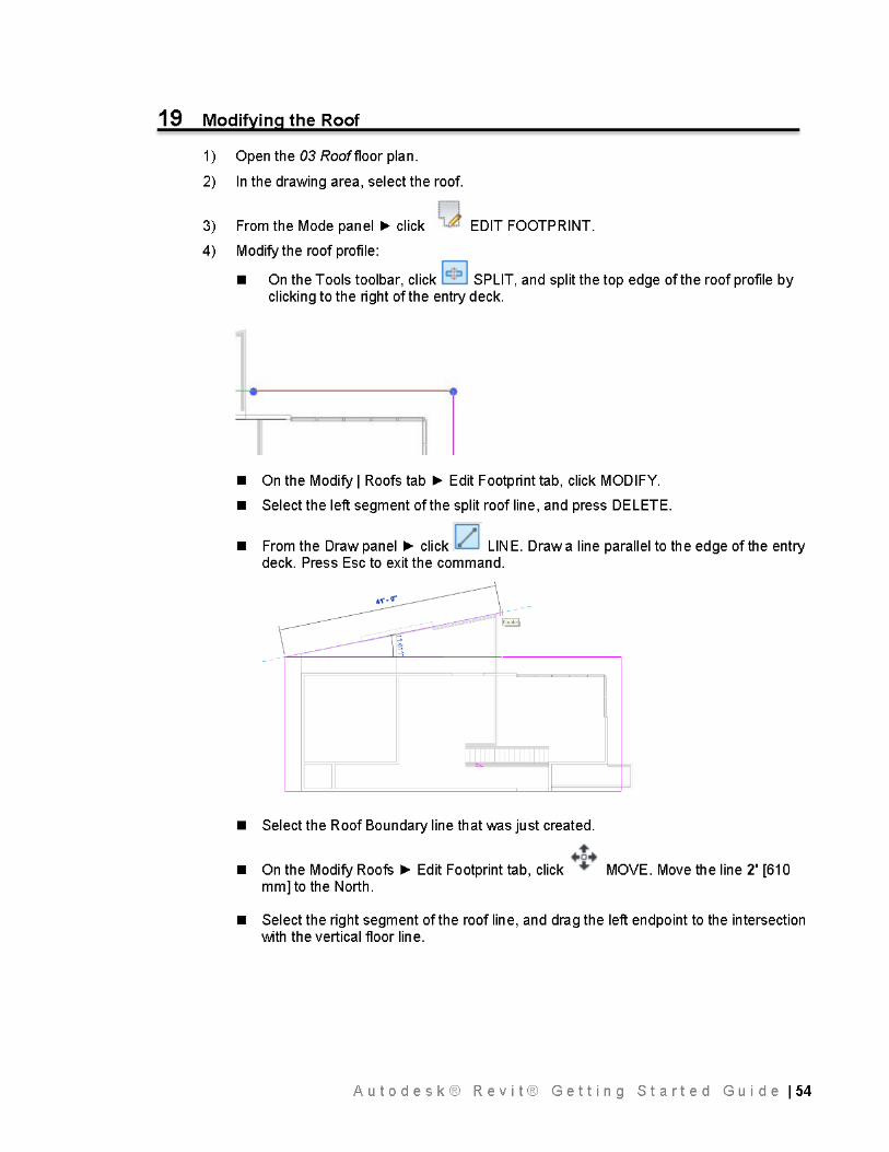
1 ) Open the 03 Roof floor plan.
2) Draw a roof line:
• Click Architecture tab ~ Roof drop-doWTI ~ ROOF BY FOOTPRINT.
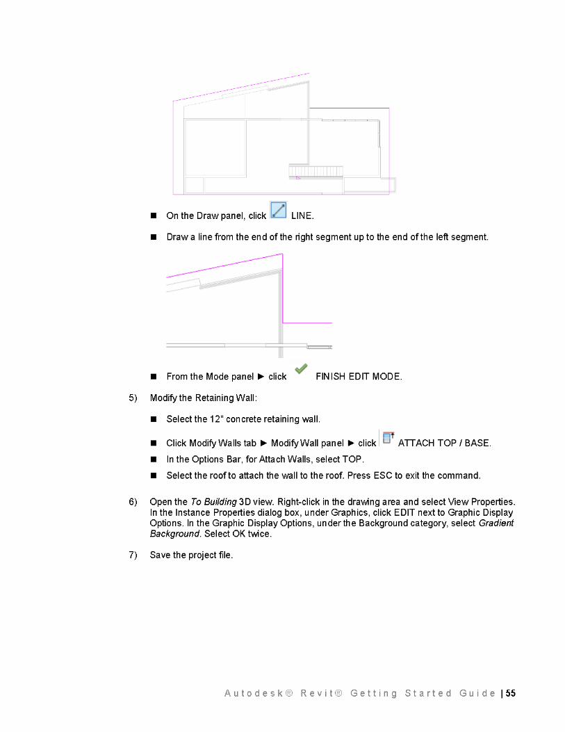
• On the Draw panel, click IZl LINE.
• In the Options Bar, verify that Defines slope is selected.
• To draw the first roof segment, begin at the bottom left and trace the exterior edge of the South wall by selecting the left wall endpoint and the intersection of the South and far-east wall.
A u t o d e s k ® R e v i t ® G e t t i n g S t a r t e d G u i d e I 24
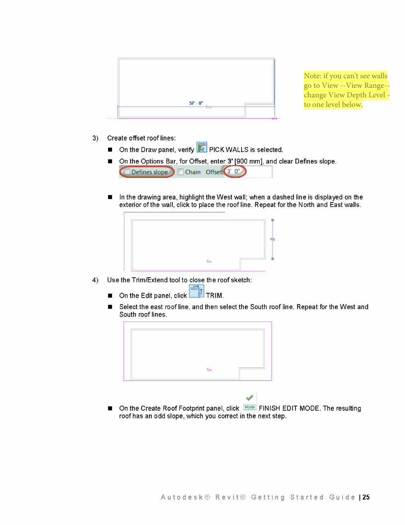
3)
57' - 0" =
Create offset roof lines:
• On the Draw panel, verify lliifl PICK WALLS is selected.
• On the 0 tions Bar, for Offset, enter 3' 900 mm], and clear Defines slope.
• In the drawing area, highlight the West wall; \J\lhen a dashed line is displayed on the exterior of the wall, click to place the roof line. Repeat for the North and East walls.
If 4) Use the Trim/Extend tool to close the roof sketch:
• On the Edit panel, click 1 =~1r l TRIM.
• Select the east roof line, and then select the South roof line. Repeat for the West and South roof lines.
• On the Create Roof Footprint panel, click ~e I FINISH EDIT MODE. The resulting roof has an odd slope, which you correct in the next step.
A u t o d e s k ® R e v i t ® G e t t i n g S t a r t e d G u i d e I 25
Note: if you can't see walls go to View --View Range--change View Depth Level - to one level below.
I
I I
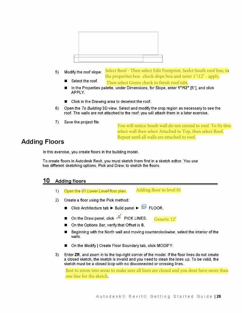
5) Modify the roof slope:
• Select the roof.
• In the Properties palette, under Dimensions, for Slope, enter 1"/12" [5°), and click APPLY.
• Click in the Drawing area to deselect the roof.
6) Open the To Building 3D view. Select and modify the crop region as necessary to see the roof. The walls are not attached to the roof; you will attach them in a later exercise.
7) Save the project file.
Adding Floors
In this exercise, you create floors in the building model.
To create floors in Autodesk Revit, you must sketch them first in a sketch editor. You use two different sketching options, Pick and Draw, to sketch the floors.
10 Adding floors
1 ) Open the 01 Lower Leve/ floor pl an.
2) Create a floor using the Pick method:
• Click Architecture tab~ Build panel~ ~ FLOOR.
• On the Draw panel, click "'~ PICK LINES.
• On the Options Bar, verify that Offset is 0.
• Beginning with the North wall and moving counterclockwise, select the interior of the walls.
• On the Modify I Create Floor Boundary tab, click MODIFY.
3) Enter ZR, and zoom in to the top-right corner of the model. If the floor lines do not create a closed sketch, the sketch is invalid and you need to clean the lines up. To be valid, the sketch must be a closed loop with no disconnected or crossing lines.
A u t o d e s k ® R e v i t ® G e t t i n g S t a r t e d G u i d e I 26
Select Roof - Then select Edit Footprint, Seelct South roof line, in the properites box- check slope box and neter 1"/12" - apply.Then select Green check to finish roof edit.
You will notice South wall do not extend to roof. To fix this: select wall then select Attached to Top, then select Roof. Repeat until all walls are attached to roof.
Generic 12"
Best to zoom into areas to make sure all lines are closed and you dont have more than one line for the sketch.
Adding floor to level 01
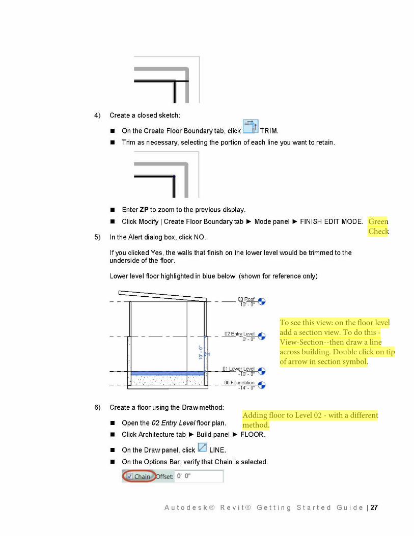
4) Create a closed sketch:
• On the Create Floor Boundary tab, click i =~,t J TRIM. • Trim as necessary, selecting the portion of each line you want to retain.
• Enter ZP to zoom to the previous display.
• Click Modify I Create Floor Boundary tab~ Mode panel~ FINISH EDIT MODE.
5) In the Alert dialog box, click NO.
If you clicked Yes, the walls that finish on the lower level would be trimmed to the underside of the floor.
Lower level floor highlighted in blue below. (shown for reference only)
~=======~;;;:;:::;l- --- O] RQ_QLI\ 10·~
_ _ _ _ 02 Enny Level IC\ o·~
-~~1--------+---t>t--~o-1 -r=~~Level IC\ - 10'~
: . : ·.· ' ? '
--i-i-~"~,·-·"-"· ._· _· : ~· ~: ~__.._·~· · _,__:· .........._+- _ 00 Fou!]_da~ -14'~
6) Create a floor using the Draw method:
• Open the 02 Entry Leve/floor plan.
• Click Architecture tab ~ Build panel ~ FLOOR.
• On the Draw panel, click IZI LINE.
• On the Options Bar, verify that Chain is selected .
../ Chain ffset: O' o·
A u t o d e s k ® R e v i t ® G e t t i n g S t a r t e d G u i d e I 27
Green Check
To see this view: on the floor level add a section view. To do this - View-Section--then draw a line across building. Double click on tip of arrow in section symbol.
Adding floor to Level 02 - with a different method.
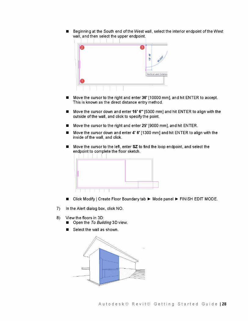
• Beginning at the South end of the West wall, select the interior endpoint of the West wall, and then select the upper endpoint. I I I I I
\ I
0
• Move the cursor to the right and enter 36' [10000 mm], and hit ENTER to accept. This is kno\J\111 as the direct distance entry method.
• Move the cursor do\J\111 and enter 16' 6" [5300 mm] and hit ENTER to align with the outside of the wall, and click to specify the point.
• Move the cursor to the right and enter 25' [9000 mm], and hit ENTER.
• Move the cursor do\J\111 and enter 4' 6' [1300 mm] and hit ENTER to align with the inside of the wall, and click.
• Move the cursor to the left, enter SZ to find the loop endpoint, and select the endpoint to complete the floor sketch.
J • Click Modify I Create Floor Boundary tab~ Mode panel~ FINISH EDIT MODE.
7) In the Alert dialog box, click NO.
8) View the floors in 3D: • Open the To Building 3D view.
• Select the wall as shown.
A u t o d e s k ® R e v i t ® G e t t i n g S t a r t e d G u i d e I 28
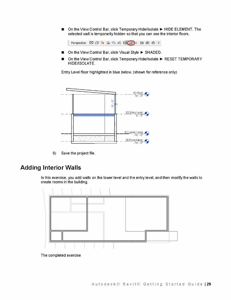
• On the View Control Bar, click Temporary H ide/lsolate ~ HI DE ELEM ENT. The selected wall is temporarily hidden so that you can see the interior floors.
• On the View Control Bar, click Visual Style~ SHADED.
• On the View Control Bar, click Temporary Hide/Isolate~ RESET TEMPORARY HI DE/ISOLATE.
Entry Level floor highlighted in blue below. (shoWTI for reference only)
-=-=========~;;;;;:::;i_ ___ OJ Roof IC\ 1 0·~
0 ;
----- --- +----- _ 02 Entry Level IC\ o·~
-~--t-1--------'---t-t--......-O l_L=ow~Level IC\ - 1 0'~
--~-~'"-· ."--': ·-~--'-'--··. _,._ .._. :~ . . _,__·~ ~'· '~ _ 00 Fouo_da~ -14'~
. . : . ; ·. ·
9) Save the project file.
Adding Interior Walls
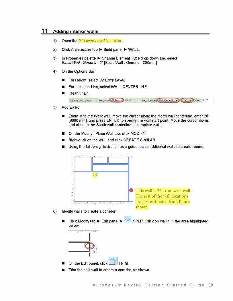
In this exercise, you add walls on the lower level and the entry level, and then modify the walls to create rooms in the building.
\ ~ ~
Ii J
\
I II II I I I I l I
I
l I The completed exercise
A u t o d e s k ® R e v i t ® G e t t i n g S t a r t e d G u i d e I 29
11 Adding interior walls
1 ) Open the 01 Lower Leve/ floor pl an.
2) Click Architecture tab ~ Build panel ~WALL.
3) In Properties palette ~ Change Element Type drop-do\J\111 and select Basic Wall: Generic - 6" [Basic Wall: Generic - 200mm].
4) On the Options Bar:
• For Height, select 02 Entry Level.
• For Location Line, select WALL CENTERLINE.
• Clear Chain.
Modify I Place Wall I Heigh • <92 Enn • ) 20 o· l ocation Line<Sf a11 Centerlin • ) ~ffset: ff O"
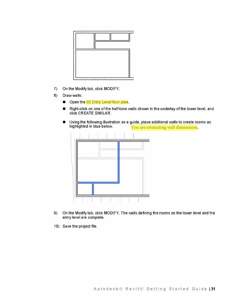
5) Add walls:
• Zoom in to the West wall, move the cursor along the North wall centerline, enter 26' [8000 mm], and press ENTER to specify the wall start point. Move the cursor down, and click on the South wall centerline to complete wall 1.
• On the Modify I Place Wall tab, click MODIFY.
• Right-click on the wall, and click CREATE SIMILAR.
• Using the following illustration as a guide, place additional walls to create rooms.
. . • .
I II I ; I I
0 '
... , . . . ... . . .. . .. ,
6) Modify walls to create a corridor:
• Click Modify tab ~ Edit panel ~ le!:> J SPLIT. Click on wall 1 in the area highlighted below.
• On the Edit panel, click 1 =~1r l TRIM.
• Trim the split wall to create a corridor, as sho\J\111.
A u t o d e s k ® R e v i t ® G e t t i n g S t a r t e d G u i d e I 30
This wall is 26' from west wall.The rest of the wall locations are just estimated from figure shown.
26'
I II I
7) On the Modify tab, click MODIFY.
8) Drawwalls:
• Open the 02 Entry Leve/floor plan.
• Right-click on one of the half-tone walls sho\J\111 in the underlay of the lower level, and click CREATE SIMILAR.
• Using the following illustration as a guide, place additional walls to create rooms as highlighted in blue below.
I I I
I
\ I
I
9) On the Modify tab, click MODIFY. The walls defining the rooms on the lower level and the entry level are complete.
10) Save the project file.
A u t o d e s k ® R e v i t ® G e t t i n g S t a r t e d G u i d e I 31
You are estimating wall dimensions.
Adding Doors
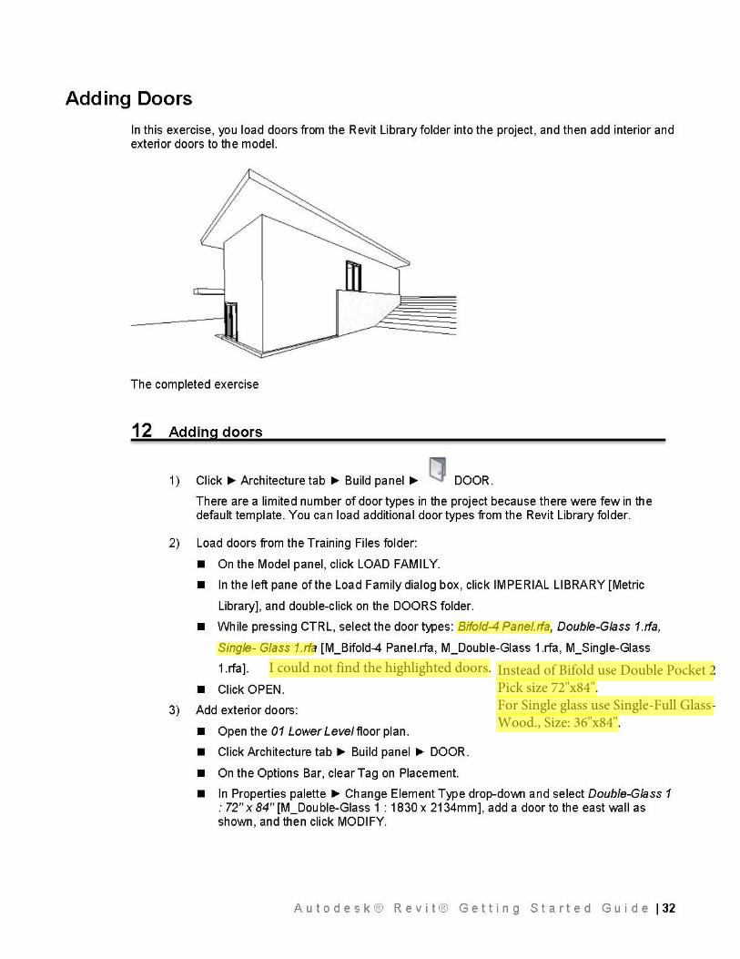
In this exercise, you load doors from the Revit Library folder into the project, and then add interior and exterior doors to the model.
The completed exercise
12 Adding doors
1) Click ~Architecture tab ~ Build panel ~ [J DOOR.
There are a limited number of door types in the project because there were few in the default template. You can load additional door types from the Revit Library folder.
2) Load doors from the Training Files folder:
• On the Model panel, click LOAD FAMILY.
• In the left pane of the Load Family dialog box, click IMPERIAL LIBRARY [Metric
Library], and double-click on the DOORS folder.
• While pressing CTRL, select the door types: Bifold-4 Panel.rfa, Double-Glass 1.rfa,
Single- Glass 1.rfa [M_Bifold-4 Panel.rfa, M_Double-Glass 1.rfa, M_Single-Glass
1.rfa].
• Click OPEN.
3) Add exterior doors:
• Open the 01 Lower Leve/floor plan.
• Click Architecture tab~ Build panel ~ DOOR.
• On the Options Bar, clear Tag on Placement.
• In Properties palette ~ Change Element Type drop-do\J\111 and select Double-Glass 1 : 72" x 84" [M_Double-Glass 1 : 1830 x 2134mm], add a door to the east wall as shown, and then click MODIFY.
A u t o d e s k ® R e v i t ® G e t t i n g S t a r t e d G u i d e I 32
I could not find the highlighted doors. Instead of Bifold use Double Pocket 2Pick size 72"x84".For Single glass use Single-Full Glass-Wood., Size: 36"x84".
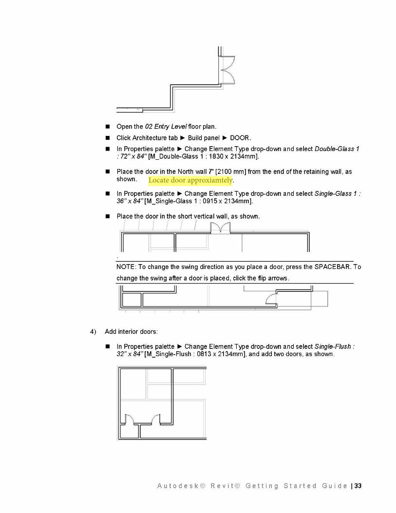
• Open the 02 Entry Leve/floor plan.
• Click Architecture tab..,.. Build panel ..,.. DOOR.
• In Properties palette ..,.. Change Element Type drop-down and select Double-Glass 1 : 72" x 84" [M_Double-Glass 1 : 1830 x 2134mm].
• Place the door in the North wall 7' [2100 mm] from the end of the retaining wall, as shown.
• In Properties palette ..,.. Change Element Type drop-down and select Single-Glass 1: 36" x 84" [M_Single-Glass 1 : 0915 x 2134mm].
• Place the door in the short vertical wall, as shown.
I I I I M
Ill I~ I II
NOTE: To change the swing direction as you place a door, press the SPACE BAR. To
change the swing after a door is placed, click the flip arrows.
1101 } (
II
4) Add interior doors:
• In Properties palette ..,.. Change Element Type drop-down and select Single-Flush: 32" x 84"[M_Single-Flush: 0813 x 2134mm], and add two doors, as shown.
A u t o d e s k ® R e v i t ® G e t t i n g S t a r t e d G u i d e I 33
Locate door approxiamtely.
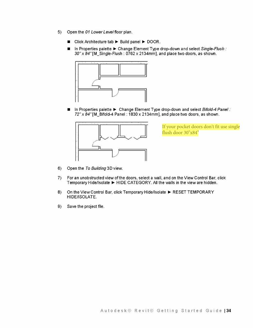
5) Open the 01 Lower Leve/floor plan.
• Click Architecture tab..,.. Build panel ..,.. DOOR.
• In Properties palette ..,.. Change Element Type drop-down and select Single-Flush: 30" x 84"[M_Single-Flush: 0762 x 2134mm], and place two doors, as shown.
. . .
• In Properties palette ..,.. Change Element Type drop-down and select Bifold-4 Panel: 72" x 84" [M_Bifold-4 Panel : 1830 x 2134mm], and place two doors, as shown.
. . .
I
6) Open the To Building 3D view.
7) For an unobstructed view of the doors, select a wall, and on the View Control Bar, click Temporary Hide/Isolate ..,.. HIDE CATEGORY. All the walls in the view are hidden.
8) On the View Control Bar, click Temporary Hide/Isolate ..,.. RESET TEMPORARY HI DE/ISOLATE.
9) Save the project file.
Autodesk® Revit® Getting Started Guide 134
If your pocket doors don't fit use single flush door 30"x84"
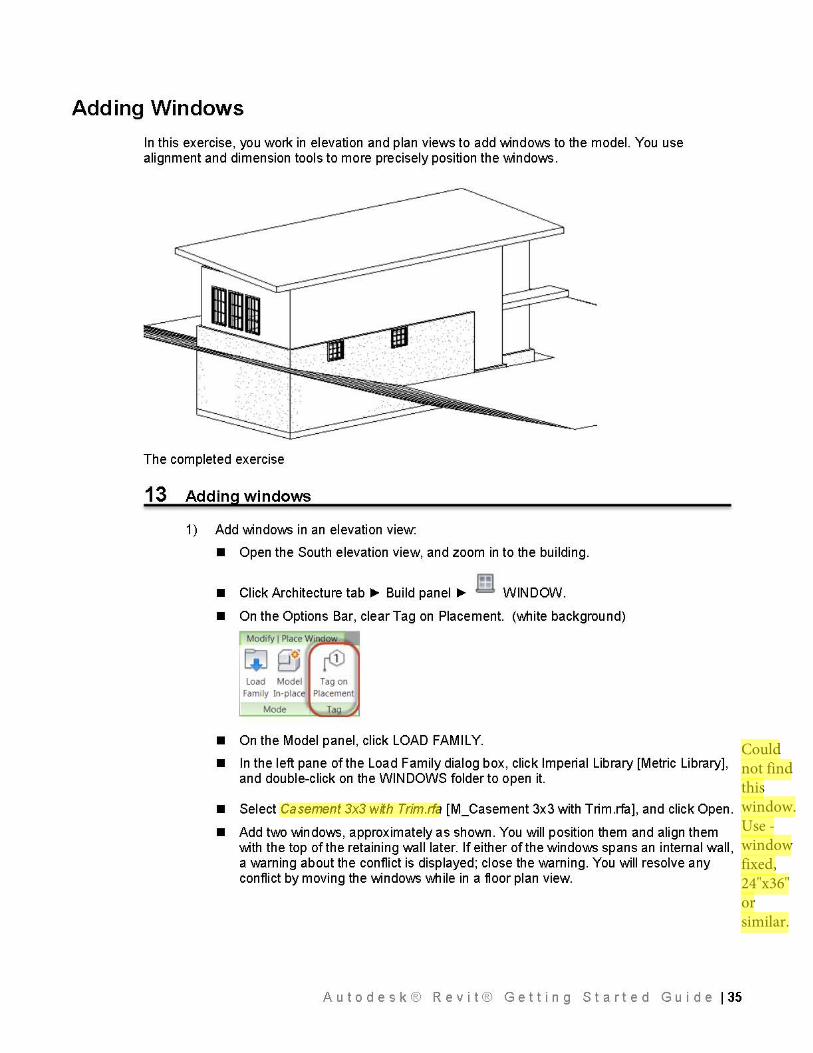
Adding Windows
In this exercise, you work in elevation and plan views to add windows to the model. You use alignment and dimension tools to more precisely position the windows.
The completed exercise
13 Adding windows
1) Add windows in an elevation view:
• Open the South elevation view, and zoom in to the building.
~ • Click Architecture tab..,.. Build panel ..,.. WINDOW.
• On the Options Bar, clear Tag on Placement. (white background)
r
li] 0 r<D Load Model Tag on
Family In-place Placement
Mode Tag
• On the Model panel, click LOAD FAMILY.
• In the left pane of the Load Family dialog box, click Imperial Library [Metric Library], and double-click on the WINDOWS folder to open it.
• Select Casement 3x3 with Trim.rfa [M_Casement 3x3 with Trim.rfa], and click Open.
• Add two windows, approximately as shown. You will position them and align them with the top of the retaining wall later. If either of the windows spans an internal wall, a warning about the conflict is displayed; close the warning. You will resolve any conflict by moving the windows while in a floor plan view.
A u t o d e s k ® R e v i t ® G e t t i n g S t a r t e d G u i d e I 35
Could not find this window. Use - window fixed, 24"x36" or similar.
2) Open the 01 Lower Leve/floor plan. Because the windows are at the top of the wall, they are above the current view range for the plan.
3) Modify the view range:
• In the Properties palette, under Extents, for View Range, click EDIT.
• In the View Range dialog box, for Cut plane Offset, enter 7' [2160 mm].
• Click OK. The windows are now visible in the South wall.
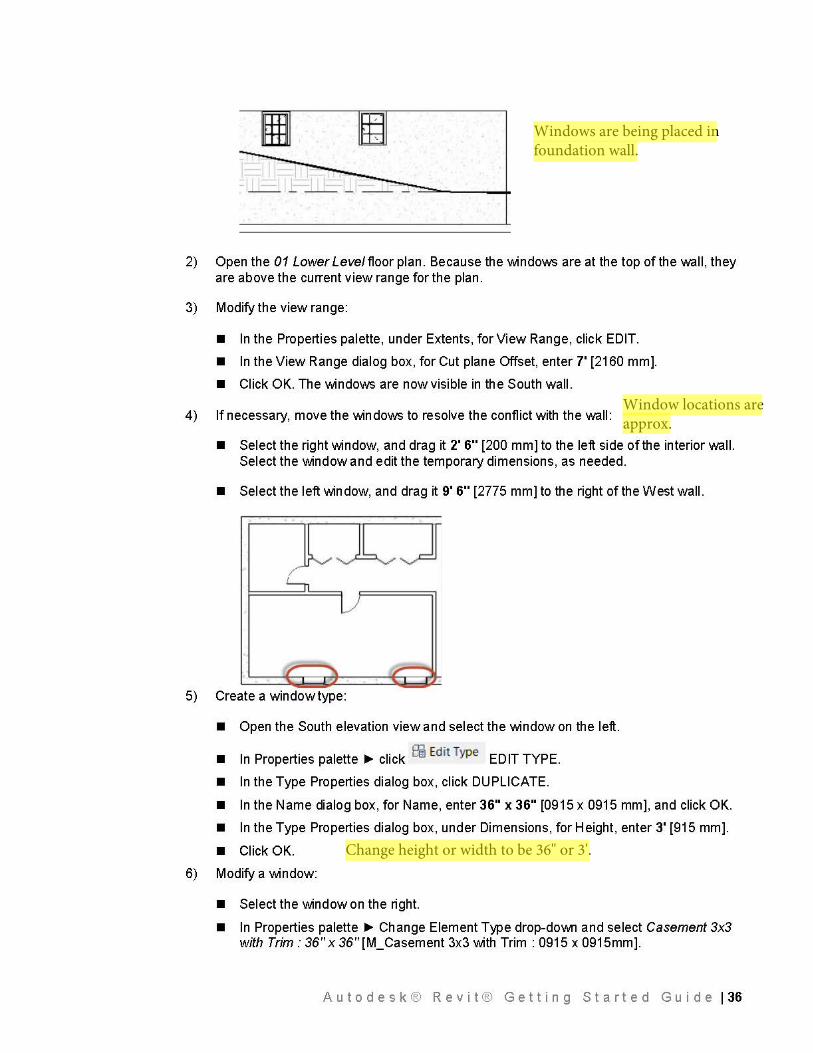
4) If necessary, move the windows to resolve the conflict with the wall:
• Select the right window, and drag it 2' 6" [200 mm] to the left side of the interior wall. Select the window and edit the temporary dimensions, as needed.
• Select the left window, and drag it 9' 6" [2775 mm] to the right of the West wall.
5) Create a window type:
• Open the South elevation view and select the window on the left.
• In Properties palette ~ click ffi Edit Type EDIT TYPE.
• In the Type Properties dialog box, click DUPLICATE.
• In the Name dialog box, for Name, enter 36" x 36" [0915 x 0915 mm], and click OK.
• In the Type Properties dialog box, under Dimensions, for Height, enter 3' [915 mm].
• Click OK.
6) Modify a window:
• Select the window on the right.
• In Properties palette ~ Change Element Type drop-do\J\111 and select Casement 3x3 with Trim: 36" x 36"[M_Casement 3x3 with Trim: 0915 x 0915mm].
A u t o d e s k ® R e v i t ® G e t t i n g S t a r t e d G u i d e I 36
Windows are being placed in foundation wall.
Window locations are approx.
Change height or width to be 36" or 3'.
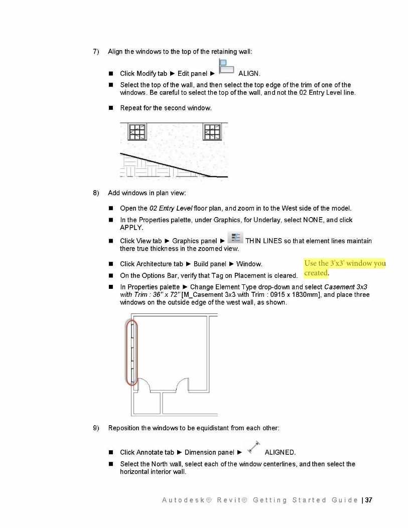
7) Align the windows to the top of the retaining wall:
• Click Modify tab~ Edit panel~ ID ALIGN.
• Select the top of the wall, and then select the top edge of the trim of one of the windows. Be careful to select the top of the wall, and not the 02 Entry Level line.
• Repeat for the second window.
~ · ~ .... ~m r'~~· -
8) Add windows in plan view:
• Open the 02 Entry Leve/floor plan, and zoom in to the West side of the model.
• In the Properties palette, under Graphics, for Underlay, select NONE, and click APPLY. --• Click View tab~ Graphics panel ~ : .:: THIN LINES so that element lines maintain there true thickness in the zoomed view.
• Click Architecture tab ~ Build panel ~Window.
• On the Options Bar, verify that Tag on Placement is cleared.
• In Properties palette ~ Change Element Type drop-do\J\111 and select Casement 3x3 with Trim: 36" x 72"[M_Casement 3x3 with Trim: 0915 x 1830mm], and place three windows on the outside edge of the west wall, as sho\J\111.
9) Reposition the windows to be equidistant from each other:
• Click Annotate tab~ Dimension panel~ / ALIGNED.
• Select the North wall, select each of the window centerlines, and then select the horizontal interior wall.
A u t o d e s k ® R e v i t ® G e t t i n g S t a r t e d G u i d e I 37
Use the 3'x3' window you created.
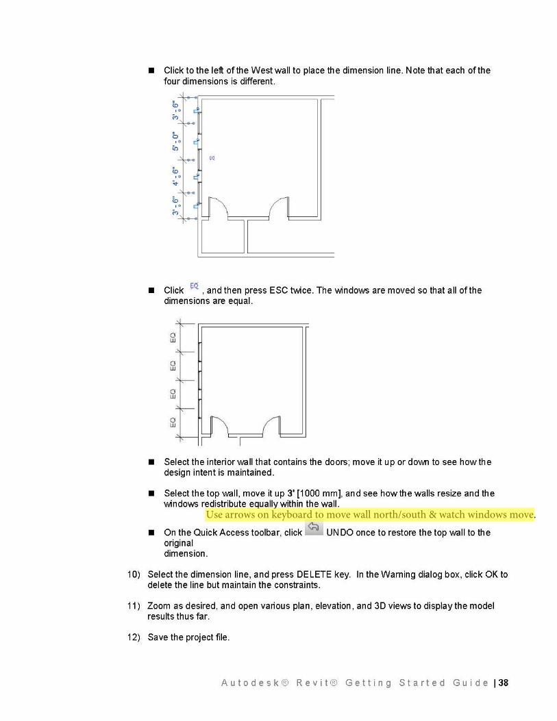
• Click to the left of the West wall to place the dimension line. Note that each of the four dimensions is different.
• Click ~ , and then press ESC twice. The windows are moved so that all of the dimensions are equal.
• Select the interior wall that contains the doors; move it up or do\J\111 to see how the design intent is maintained.
• Select the top wall, move it up 3' [1000 mm], and see how the walls resize and the windows redistribute equally within the wall.
• On the Quick Access toolbar, click ~ UN DO once to restore the top wall to the original dimension.
10) Select the dimension line, and press DELETE key. In the Warning dialog box, click OK to delete the line but maintain the constraints.
11) Zoom as desired, and open various plan, elevation, and 3D views to display the model results thus far.
12) Save the project file.
A u t o d e s k ® R e v i t ® G e t t i n g S t a r t e d G u i d e I 38
Use arrows on keyboard to move wall north/south & watch windows move.
Adding a Curtain Wall
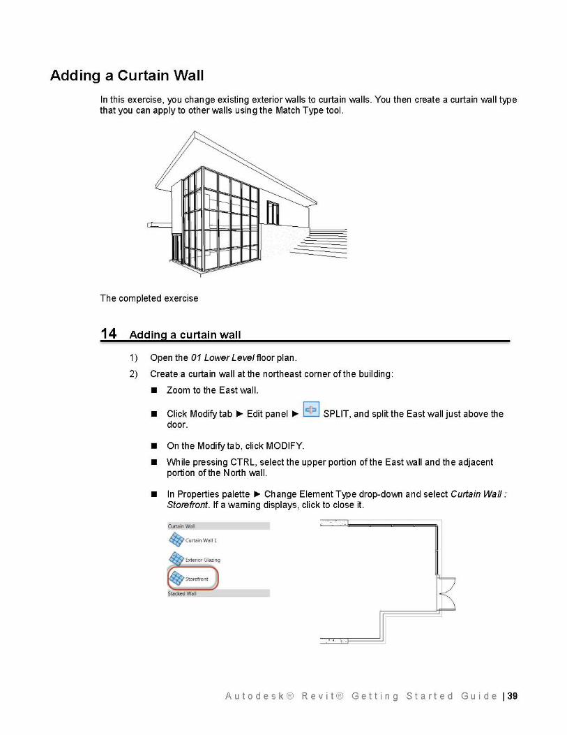
In this exercise, you change existing exterior walls to curtain walls. You then create a curtain wall type that you can apply to other walls using the Match Type tool.
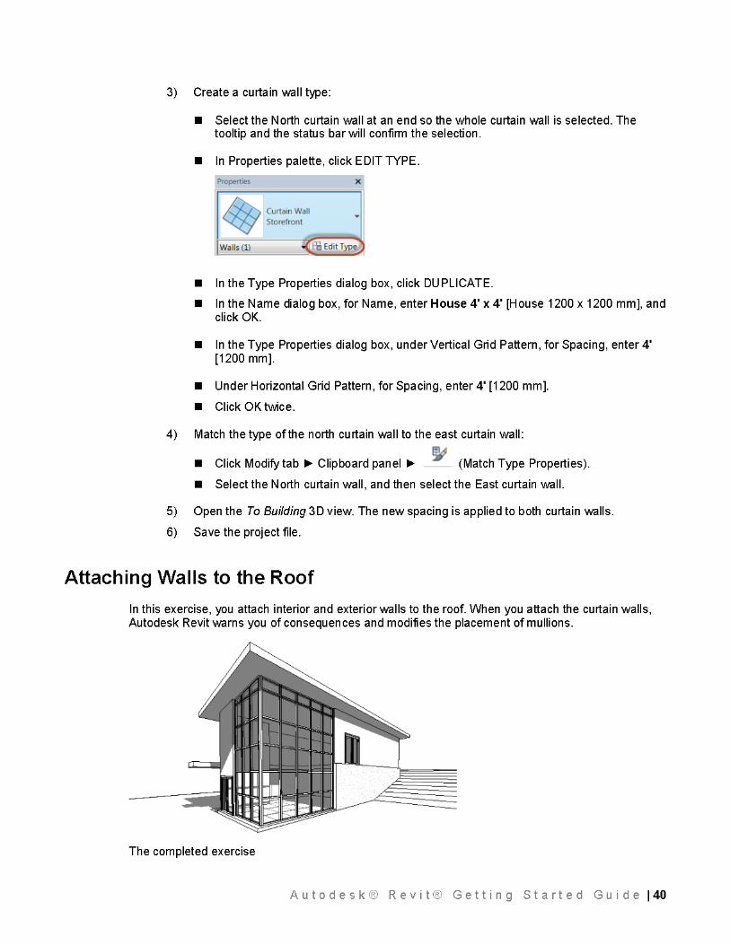
The completed exercise
14 Adding a curtain wall
1 ) Open the 01 Lower Leve/ floor pl an.
2) Create a curtain wall at the northeast corner of the building:
• Zoom to the East wall.
• Click Modify tab ~ Edit panel ~ le!~ I SPLIT, and split the East wall just above the door.
• On the Modify tab, click MODIFY.
• While pressing CTRL, select the upper portion of the East wall and the adjacent portion of the North wall.
• In Properties palette ~ Change Element Type drop-down and select Curtain Wall: Storefront. If a warning displays, click to close it.
Curtain Wall
~Curtain Wall l
Exterior Glazing
Storefront
A u t o d e s k ® R e v i t ® G e t t i n g S t a r t e d G u i d e I 39
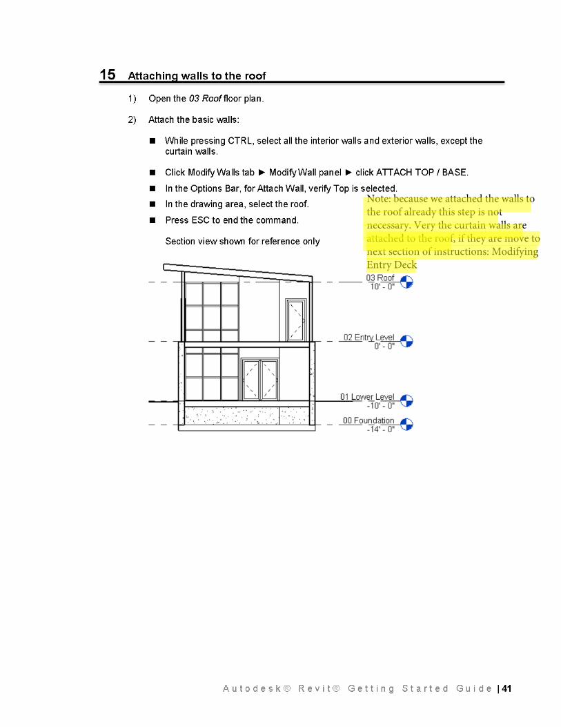
Note: because we attached the walls to the roof already this step is not necessary. Very the curtain walls are attached to the roof, if they are move to next section of instructions: Modifying Entry Deck
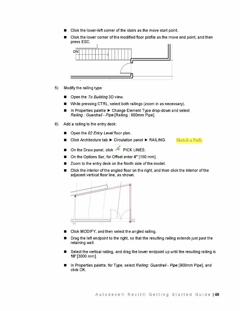
Sketch a Path.
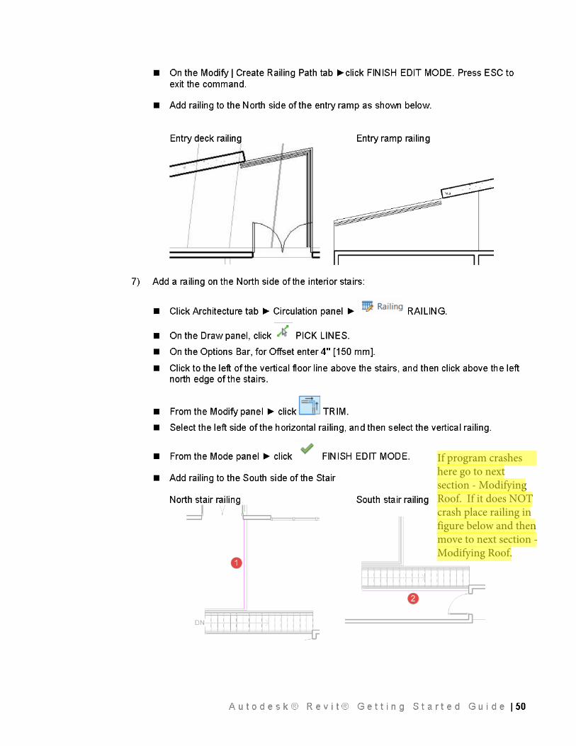
If program crashes here go to next section - Modifying Roof. If it does NOT crash place railing in figure below and then move to next section - Modifying Roof.
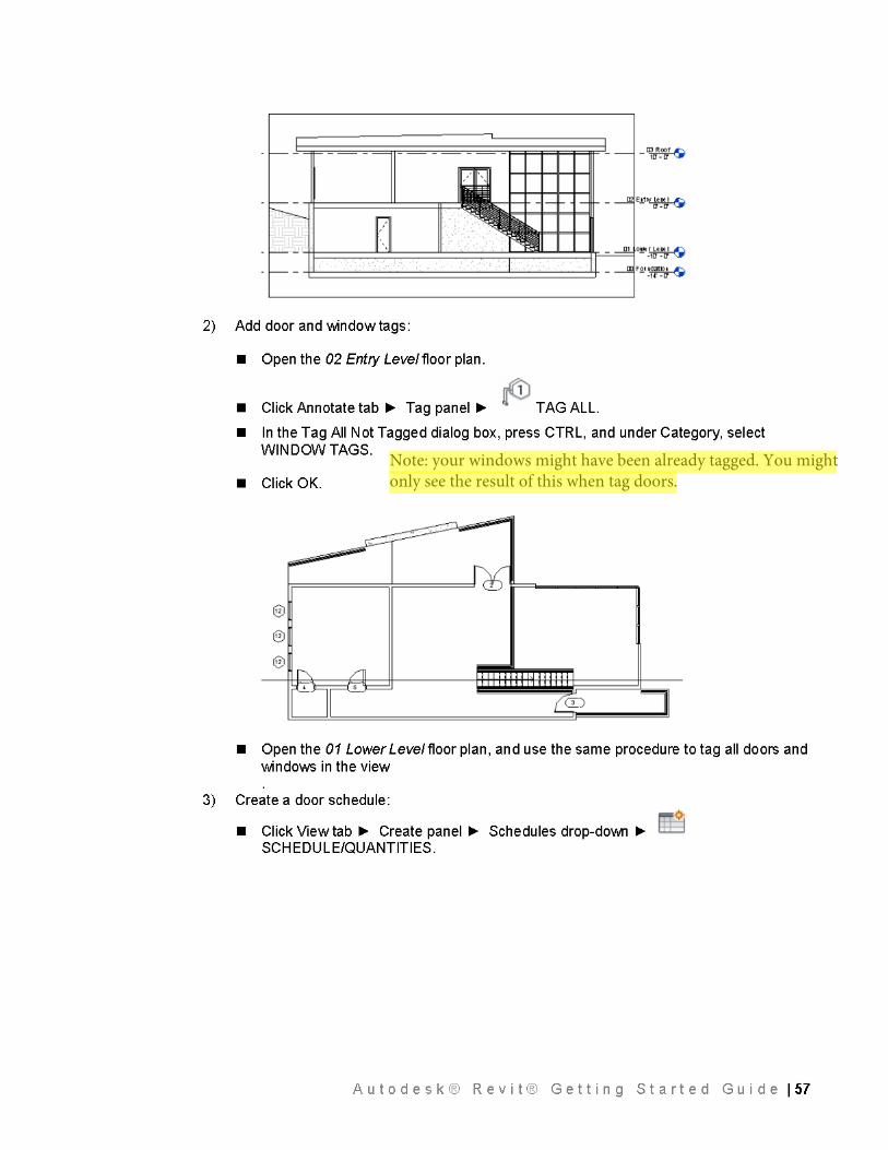
Note: your windows might have been already tagged. You might only see the result of this when tag doors.
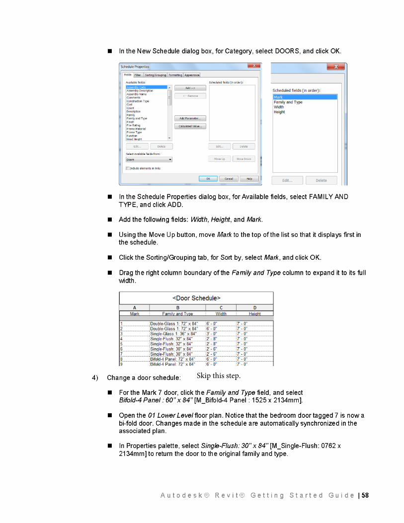
Skip this step.
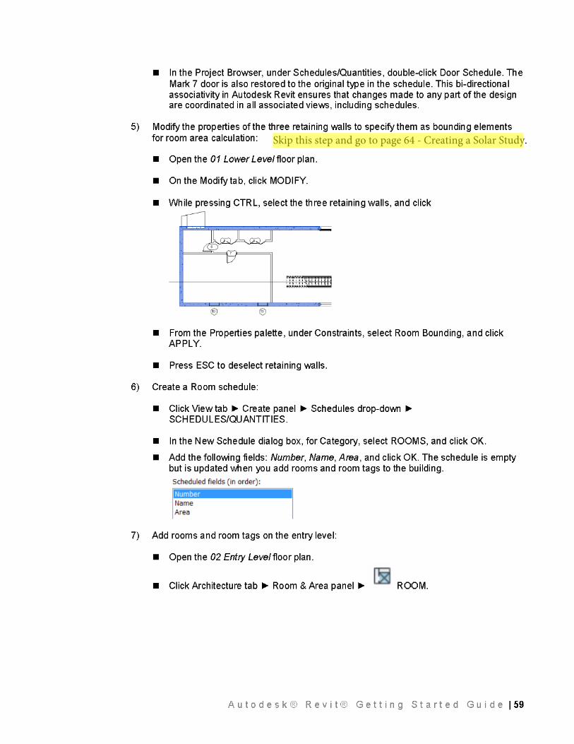
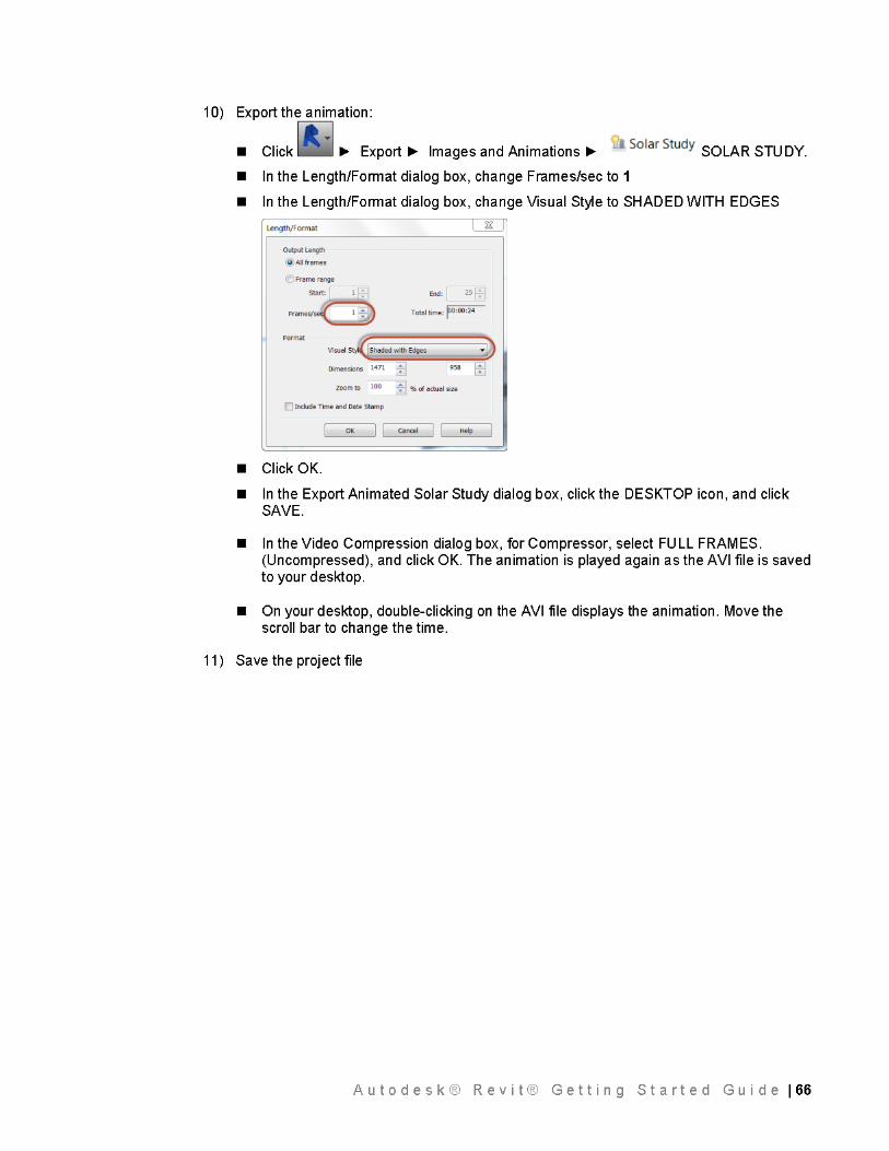
Skip this step and go to page 64 - Creating a Solar Study.
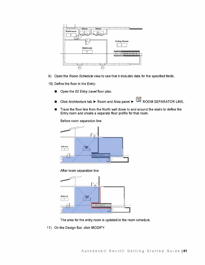
Start here again.
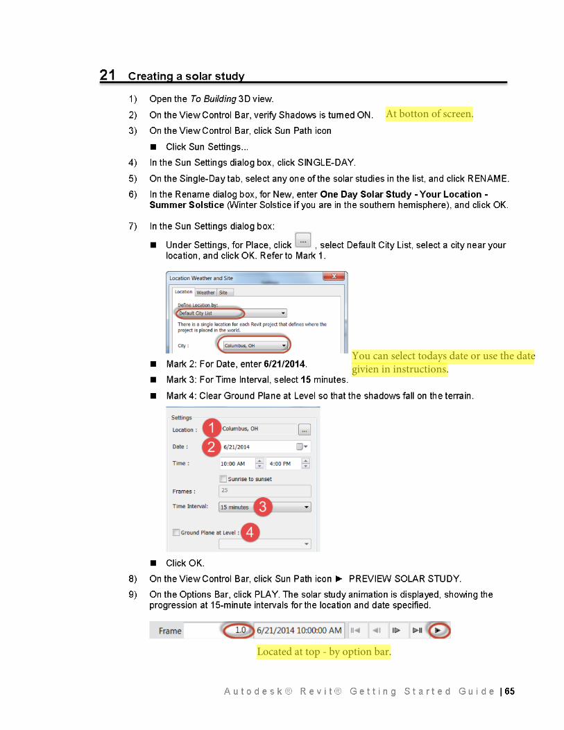
At botton of screen.
You can select todays date or use the date givien in instructions.
Located at top - by option bar.
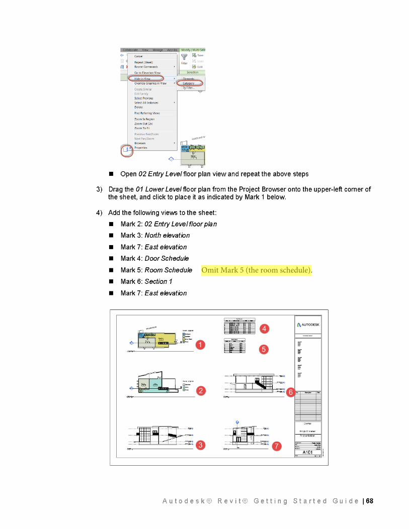
Omit Mark 5 (the room schedule).
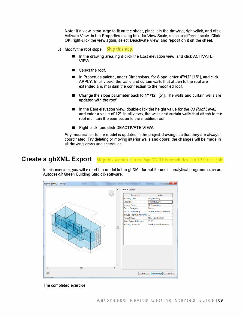
Skip this section. Go to Page 73. This concludes Lab 1!! Great job!
Skip this step.