Embed Size (px)
Citation preview
Progress in Nuclear Energy. 1982, Vol. 9, pp. 595-604 007%6530/82/03595-1055.00/0 Printed in Great Britain. All rights reserved. Copyright © 1982 Pergamon Press Ltd
A U T O M A T E D VIBRATION MONITORING SYSTEM FOR WWER-440 N U C L E A R POWER P L A N T
DIAGNOSTICS AND SURVEILLANCE
E. HOLLO, P . SIKLOSSY, ZS. TOTH
Institute for Electrical Power Research H-1368 Budapest, POB 233, Hungary
ABSTRACT
This paper summarizes activities and early experiences of Institute for Elec- trical Power Research concerning an automated vibration monitoring system /AVMS/ for WWER-440 nuclear power plant diagnostics and surveillance. Possibilities of using mechanical and flow induced vibration noise analysis for safety moni- toring, anomaly detection and failed condition diagnosis are discussed. Hard- ware configuration and software capabilitites of the particular AVMS system are described in details, as well as laboratory experiences, future software devel- opment and hardware improvement areas are presented.
KEYWORDS
WWER-type reactors; on-line surveillance; automatic vibration monitoring, flow induced vibrations.
INTRODUCTION
One approach toward improving the overall availability of a PWR nuclear power plant is continuous monitoring and evaluation of vibrational characteristics of critical machines and mechanical parts both in primary and secondary cir- cuits. The large number of critical machines, equipments and their components to be monitored results need for a computer based automated surveillance sys- tem. The complex vibration related information /acceleration, circuit pressure fluctuation/ of individual mechanical parts must be analyzed periodically, i.e. particular spectral amplitudes and frequencies must be identified, their sig- nificant change and modification clearly stated, and for further processing recorded on magnetic discs. Such an analysis work requires thorough knowledge of plant technology, as well as experts specialised in vibrational instrument- ation and computer software techniques.
In the field of general vibration analysis rapid advances can be observed in the near past. To apply the developed methods, techniques, and equipments in WWER-440 nuclear power plants and to assess vibrational characteristics of crit- ical mechanical parts, an a-priori theoretical and laboratory work has been car- ried out in our Institute since 1978 /Sikl6ssy, 1978, 1981; Marcsa, 1979; T6th, 1980; Hol16, 1980/. The a-priori work relates to
- definitions of design criteria of an AVMS system to be installed in WWER-440 NPPs /selection of mechanical parts to be monitored, field of vibrational
595

596 E. HOLL6, P. SIKL6SSY and Zs. T6TH
characteristics, diagnostic aims, etc./, - development of basic software algorithms and programs for both on-line and
off-line data evaulation, - laboratory measurements to gain experiences in stochastic signal transmis-
sion for long distances and to verify complete data channels /sensors-trans- mission lines-processor/,
- industrial measurements to test the date recording system within industrial circumstances /gas and steam turbine measurements/.
Following sections provide an overview of these a-priori expriences of the present AVMS system under development, and of the current research and devel- opment work.
DISCUSSION
In 1978 a joint R/D program was started by Institute for Electrical Power Re- search /VEIKI/ and Central Research Institute for Physics /KFKI/ to develop a plant diagnostic system for WWER-440 units. In the frame of this work KFKI in responsible for development of neutron noise diagnostic sub-system and VEIKI for design and installation of automated vibration monitoring sub-system both in primary and secondary circuits.
In details, VEIKI in responsible for overall AVMS system design, system hard- ware component selection, sensor and pre-amplifier installation, data proces- sing configuration installation, and software development. Presently all system components have been selected, measuring lines are under functional tests, the processor has been mainly assembled in VEIKI laboratory, and the basic software in under verification.
The plant diagnostic system under development is first time to be installed in PAKS Nuclear Power Station in Hungary.
WWER-440 UNIT CHARACTERISTICS
Some main characteristics of WWER-440 units are summarized in Table i.
TABLE 1 Main Characteristics of WWER-440 NPP Units
Gross electrical/thermal power 440 MW(e)/1375 MW (th)
Material/enrichment/cladding No. of assemblies/pins Active core height/diameter Control rods Reactor vessel material Reactor height/diameter/wall thickness
UO /3,5% /Zr-Nb 3 4 3 / 1 2 6 - h e x a g o n a l 2,5 m/2,88 m 37 pc. SS and boron SS clad carbon steel 13,4 m/3,6m/145 mm
No. of primary loops 6 Pressure 12,5 MPa Core inlet/outlet temperature 27OOC/3OO°C
No. of turbines 2 Speed 3OOO/min Steam conditions 4,5 MPa/255°C
From the aspect of vibration monitoring, number and structure of critical equi- pments where surveillance in considered desirable, are of special interests. Each WWER-440 unit has si~ primary loops, i.e. the reactor is served by six primary pumps, six steam generators, twelve main valves, one pressurizer, and the connecting pipelines. The secondary circuit comprises two identical turbine generator systems, each of 220 MWe capacity.
Nuclear processes are controlled by 37 control rod assemblies connected to the
WWER-440 nuclear power plant diagnostics and surveillance 597
top of the reactor wessel. Primary circulating pumps are vertical electric motor driven pumps, steam ge- nerators are of horizontal tank types. All main valves are completely opened during nominal operation, the pressurizer is operated by steam pressure con- trol. Steam turbines consist of a high and a low pressure house, the latter one is devided into two parts. Turbines are supplied by saturated steam and equipped by a steam drier/separator unit between high and low pressure parts.
GENERAL DESIGN CRITERIA
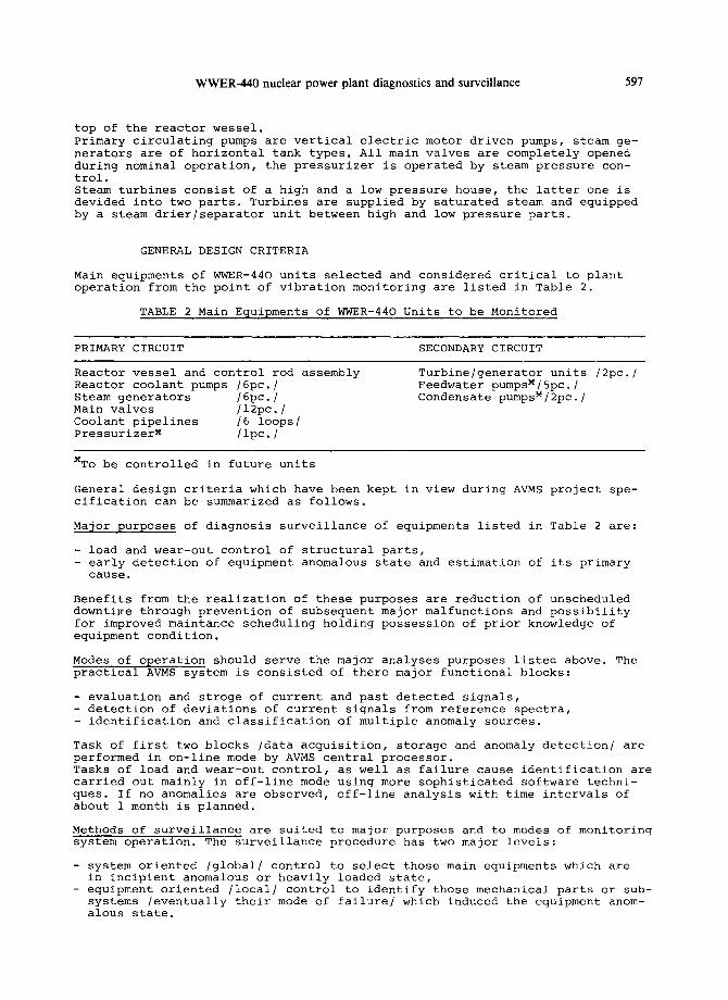
Main equipments of WWER-440 units selected and considered critical to plant operation from the point of vibration monitoring are listed in Table 2.
TABLE 2 Main Equipments of WWER-440 Units to be Monitored
PRIMARY CIRCUIT SECONDARY CIRCUIT
Reactor vessel and control rod assembly Reactor coolant pumps /6pc./ Steam generators /6pc./ Main valves /12pc./ Coolant pipelines /6 loops/ PressurizerX /ipc./
Turbine/generator units /2pc./ Feedwater pumpsX/5pc./ Condensate pumpsM/2pc./
MTo be controlled in future units
General design criteria which have been kept in view during AVMS project spe- cification can be summarized as follows.
Ma~or purposes of diagnosis surveillance of equipments listed in Table 2 are:
- load and wear-out control of structural parts, - early detection of equipment anomalous state and estimation of its primary
cause.
Benefits from the realization of these purposes are reduction of unscheduled downtime through prevention of subsequent major malfunctions and possibility for improved maintance scheduling holding possession of prior knowledge of equipment condition.
Modes of operation should serve the major analyses purposes listed above. The practical ArMS system is consisted of there major functional blocks:
- evaluation and stroge of current and past detected signals, - detection of deviations of current signals from reference spectra, - identification and classification of multiple anomaly sources.
Task of first two blocks /data acquisition, storage and anomaly detection/ are performed in on-line mode by AVMS central processor. Tasks of load and wear-out control, as well as failure cause identification are carried out mainly in off-line mode using more sophisticated software techni- ques. If no anomalies are observed, off-line analysis with time intervals of about 1 month is planned.
Methods of surveillance are suited to major purposes and to modes of monitoring system operation. The surveillance procedure has two major levels:
- system oriented /global/ control to select those main equipments which are in incipient anomalous or heavily loaded state,
- equipment oriented /local/ control to identify those mechanical parts or sub- systems /eventually their mode of failure/ which induced the equipment anom- alous state.
598 E. HOLL6, P. SIKLOSSY and Zs. T6TH
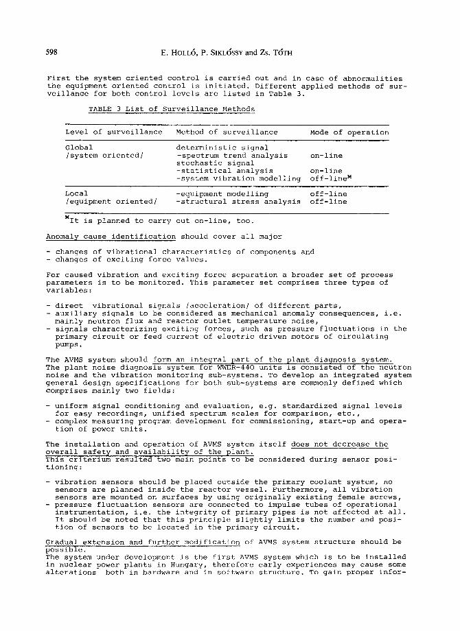
First the system oriented control is carried out and in case of abnormalities the equipment oriented control is initiated. Different applied methods of sur- veillance for both control levels are listed in Table 3.
TABLE 3 List of Surveillance Methods
Level of surveillance Method of surveillance Mode of operation
Global deterministic signal /system oriented/ -spectrum trend analysis on-line
stochastic signal -statistical analysis on-line -system vibration modelling off-line x
Local -equipment modelling off-line /equipment oriented/ -structural stress analysis off-line
MIt is planned to carry out on-line, too.
Anomaly cause identification should cover all major
- changes of vibrational characteristics of components and - changes of exciting force values.
For caused vibration and exciting force separation a broader set of process parameters is to be monitored. This parameter set comprises three types of variables:
- direct vibrational signals /acceleration/ of different parts, - auxiliary signals to be considered as mechanical anomaly consequences, i.e.
mainly neutron flux and reactor outlet temperature noise, - signals characterizing exciting forces, such as pressure fluctuations in the
primary circuit or feed current of electric driven motors of circulating pumps.
The AVMS system should form an integral part of the plant diagnosis system. The plant noise diagnosis system for WWER-440 units is consisted of the neutron noise and the vibration monitoring sub-systems. To develop an integrated system general design specifications for both sub-systems are commonly defined which comprises mainly two fields:
- uniform signal conditioning and evaluation, e.g. standardized signal levels for easy recordings, unified spectrum scales for comparison, etc.,
- complex measuring program development for commissioning, start-up and opera- tion of power units.
The installation and operation of AVMS system itself does not decrease the overall safety and availability of the plant. This criterium resulted two main points to be considered during sensor posi- tioning:
- vibration sensors should be placed outside the primary coolant system, no sensors are planned inside the reactor vessel. Furthermore, all vibration sensors are mounted on surfaces by using originally existing female screws,
- pressure fluctuation sensors are connected to impulse tubes of operational instrumentation, i.e. the integrity of primary pipes is not affected at all. It should be noted that this principle slightly limits the number and posi- tion of sensors to be located in the primary circuit.
Gradual extension and further modification of AVMS system structure should be possible. The system under development is the first AVMS system which is to be installed in nuclear power plants in Hungary, therefore early experiences may cause some alterations both in bardware and in software structure. To gain proper infor-
WWER-440 nuclear power plant diagnostics and surveillance 599
mation and to make possible these necessary modifications,
- one primary coolant loop is more widely instrumented to identify the dominant vibrational amplitudes, frequences, and directions for determination of the optimal number and location of installed sensors. This is done on shaft bear- ings of turbine/generator units, too, where multidirectional sensors are lo- cated,
- both hardware and software parts have modular structure, i.e. further meas- uring lines can be connected to the AVMS central processor and software ca- pabilities are expandable to a certain extent.
AVMS SYSTEM CHARACTERISTICS
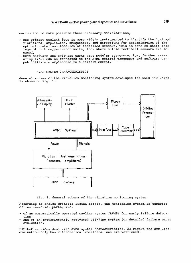
General schema of the vibration monitoring system developed for WWER-440 units is shown on Fig. i.
~,lfanume- X - Y ric Display Plotter , , Floppy L . . . . . . -~
Disc I- . . . . . .
AVMS System ~ Interface
l Signals Power
H Tope L - - Recorder F- -
Vibration Instrumentation ( sensors, amplifiers)
I NPP Process
Off-line Proces-
sor
Fig. i. General schema of the vibration monitoring system
According to design criteria listed before, the monitoring system is composed of two essential parts, i.e.
of an automatically operated on-line system /AVMS/ for early failure detec- tion, and of an intermittently activated off-line system for detailed failure cause evaluation.
Further sections deal with AVMS system characteristics. As regard the off-line evaluation only basic theoratical considerations are mentioned.
600 E. HOLL6, P. SIKL6SSY and Zs. T6TH
Hardware Description
Hardware configuration of the AVMS .system is consisted of two main parts, i.e.
- measuring chain instrumentation, comprising vibration accelerometer and primary pressure fluctuation sensors, signal preamplifiers, transmitting cable lines, and receiver amplifiers,
- data processing unit, containing multiplexers, A/D converters, fast arithmetic unit, digital computer interface, and associated control and display modules.
Instrumentation selection and installation. The sensor-cable-amplifier selec- tion is mainly determined by the following requirements:
- their technical characteristics would make the realization of surveillance functions possible with high reliability,
- specifications would satisfy encironmental requirements with long term sta- bility,
- possible standardized instrumentation with high signal to noise ratio com- patible with other process electronic equipments should be applied.
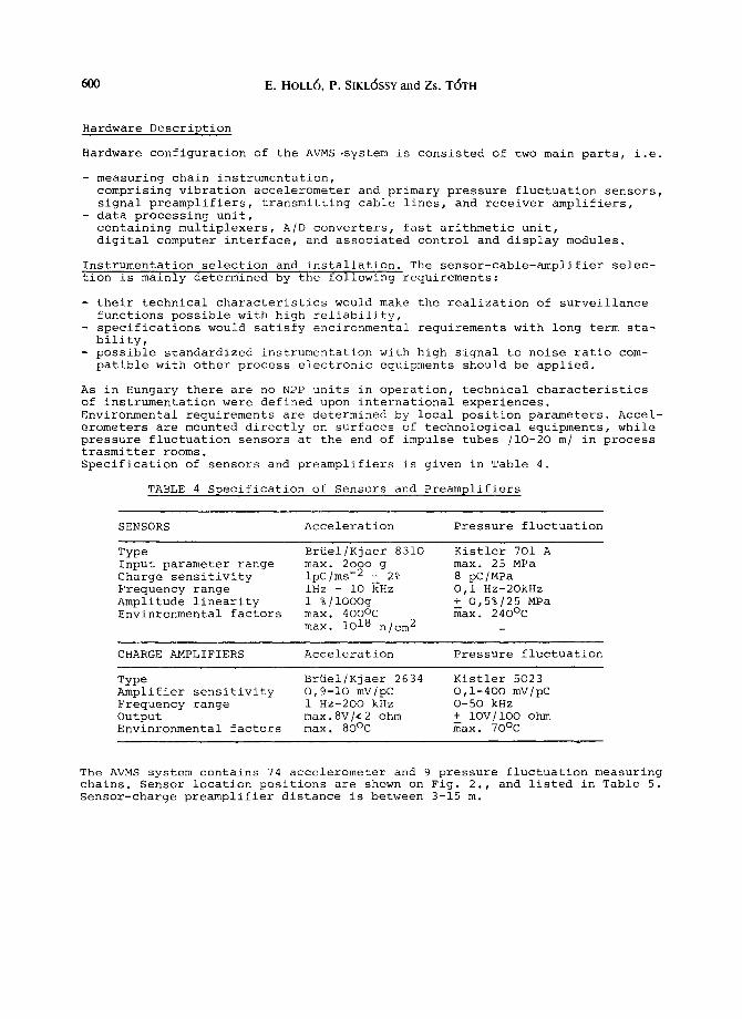
As in Hungary there are no NPP units in operation, technical characteristics of instrumentation were defined upon international experiences. Environmental requirements are determined by local position parameters. Accel- erometers are mounted directly on surfaces of technological equipments, while pressure fluctuation sensors at the end of impulse tubes /10-20 m/ in process trasmitter rooms. Specification of sensors and preamplifiers is given in Table 4.
TABLE 4 Specification of Sensors and Preamplifiers
SENSORS Acceleration Pressure fluctuation
Type Br~el/Kjaer 8310 Kistler 701 A Input parameter range max. 2ooo g max. 25 MPa Charge sensitivity ipC/ms -2 + 2% 8 pC/MPa Frequency range iHz - i0 kHz O,i Hz-2OkHz Amplitude linearity 1%/iOOOg + 0,5%/25 MPa Envinronmental factors max. 4ooOc max. 240°C
max. 1018 n/cm 2
CHARGE AMPLIFIERS Acceleration Pressure fluctuation
Type Br~el/Kjaer 2634 Kistler 5023 Amplifier sensitivity O,9-10 mV/pC O,1-400 mV/pC Frequency range 1 Hz-2OO kHz 0-50 kHz Output max.8V/,2 ohm + IOV/IOO ohm Envinronmental factors max. 80°C max. 70°C
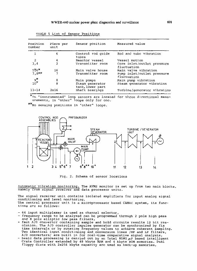
The AVMS system contains 74 accelerometer and 9 pressure fluctuation measuring chains. Sensor location positions are shown on Fig. 2., and listed in Table 5. Sensor-charge preamplifier distance is between 3-15 m.
WWER-440 nuclear power plant diagnostics and surveillance 601
TABLE 5 List of Sensor Positions
Position Piece per Sensor position Measured value number unit
1 6 Control rod guide Rod and tube vibration tubes
2 4 Reactor vessel 3t4 2 Transmitter room
5~6 M 16 7,8 ~ 7
9 x 8
i0 ~ 8
11-14 2x16
Main valve house Transmitter room
Main pumps Steam generator tank, lower part Shaft bearings
Vessel motion Core inlet/outlet pressure fluctuation Main valve vibration Pump inlet/outlet pressure fluctuation Main pump vibration Steam generator vibration
Turbine/generator vibration
MIn "instrumented" loop sensors are located urements, in "other" loops only for one.
XXNo sensing positions in "other" loops.
for three directional meas-
CONTROL ROD , ~ , PRESSURIZER ASSEMBLIES ~
\z__/__~ STEAM I I I I I I I " F I " GENERATOR
F VESSEL L, VALVE
2 4 5* 6* 7 9*8** 10"
TURBINE /GENERATOR UNIT
11 12 13 14
Fig. 2. Schema of sensor locations
Automatic vibration monitoring. The AVMS monitor is set up from two main blocks, namely from signal receiver and data processor units.
The signal receiver unit contains isolated amplifiers for input analog signal conditioning and level monitoring. The central processor unit is a microprocessor based CAMAC system, its func- tions are as follows:
- 64 input multiplexer is used as channel selector, - frequency range to be analyzed can be programmed through 2 pole high pass
and 8 pole elliptic low pass filters, fast A/D converter containing sample and hold circuits results 12 bit res- olution. The A/D controller impulse generator can be synchronized by fix time intervals or by rotating frequency values to achieve coherent sampling. Two identical input conditioning and conversion lines /HP and LP filters, A/D converters/ are built in for real-time comparative signal analysis, basic data processing is carried out by an Intel 8080~P based intelligent Crate Controller extended by 48 kbyte RAM and 4 kbyte ROM memories. Dual floppy discs with 2x256 kbyte capacity are used as back-up memories,
602 E. HOLL6, P. SIKL6SSY and Zs. T6TH
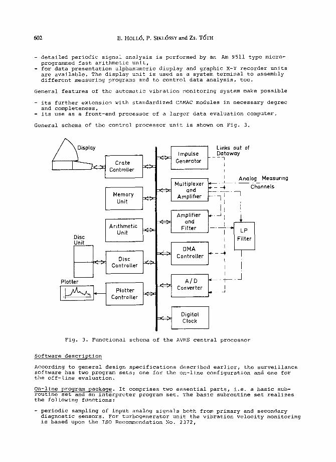
detailed periodic signal analysis is performed by an Am 9511 type micro- programmed fast arithmetic unit,
- for data presentation alphanumeric display and graphic X-Y recorder units are available. The display unit is used as a system terminal to assembly different measuring programs and to control data analysis, too.
General features of the automatic vibration monitoring system make possible
its further extension with standardized CAMAC modules in necessary degree and completeness,
- its use as a front-end processor of a larger data evaluation computer.
General schema of the control processor unit is shown on Fig. 3.
Display
Crate . . i , ~ - - L C o n t roller - -
Disc Unit [ 1..i
Plotter
.-'. J, Impulse "" I Generator
Multiplexer ~ '
Memory " ;- and -¢ . - - . -- . Amplif ier I Unit "" I
Controller I Disc . ' - . ! ~ " -4 Controller J "" I
I
- ' . ' - A / D ~ - - ,¢ - - - - - 1
Plotter ] Converter Controller ] " "
. . J Digital ~" " Clock
t Links out o f _ _D%taway
I I
I Analog Measuring Channels
Fig. 3. Functional schema of the AVMS central processor
Software description
According to general design specifications described earlier, the surveillance software has two program sets; one for the on-line configuration and one for the off-line evaluation.
On-line program package. It comprises two essential parts, i.e. a basic sub- routine set and an interpreter program set. The basic subroutine set realizes the following functions:
- periodic sampling of input analog signals both from primary and secondary diagnostic sensors. For turbogenerator unit the vibration velocity monitoring is based upon the ISO Recommendation No. 2372,
WWER-440 nuclear power plant diagnostics and surveillance 603
- programmed and delayed input selection through a 64 channel multiplexer with programmable measuring range,
- synchronized or timed A/D conversion in four frequency range between iHz-lOkHz,
- Fast Fourier Transform of 1024 sample values, Inverse Fourier Transform, calculation, averaging and storage of 400 line power spectral density func- tions,
- joint evaluation of two synchronized sample sets in frequency domain /CPSD, coherence function/, data and spectra presentation on alphanumeric display and plotter units.
The interpreter program set carries out a comparative spectrum analysis, i.e. a comparison of power spectral density function of currently measured signals with reference /zero level or averaged/ spectra. The spectrum analysis com- prises two methods, i.e.
for deterministic signals, such as turbogenerator or main primary circulating pump vibration, a spectrum trend analysis is used, for stochastic signals more detailed statistical parameter analysis based on spectrum peak shape identification will be applied.
In case of significant deviation automatic presentation of current and refer- ence spectra is initiated.
Off-line pro@ram packa@e. It has a system oriented and an equipment oriented part. The main surveillance method for both parts is based upon mechanical vi- bration modelling and detailed spectrum characteristics identification. This means that mathematical models describing system and equipment dynamics are set up, and characteristic spectrum amplitude and frequency changes are fitted to model constant variations.
The system vibration model of primary circuit is consisted of coupled discrete rigid and continuous elastic models of mechanical equipments /discrete - re- actor vessel, circulating pump, steam exchanger; continuous - pipeline/. The equipment vibration models are structurally concentrated elementary ones describing vibration characteristics of main equipment parts. To specify model parameters /mass, spring and damping values/ wide range ex- periments and measurements are planned during physical and energetic reactor start-up periods. In addition to vibration modeling mentioned above, auxiliary thermal and me- chanical stress calculations based on finite element methods are to be used periodically to decompose spectrum peaks and to detect characteristic changes.
EARLY EXPERIENCES AND FUTURE TRENDS OF DEVELOPMENT
Early experiences. Initial results of VEIKI in NPP vibration diagnostics and surveillance comprise preliminary experimental and conventional power plant measurements, as well as initial off-line interpretation of measured data.
Experimental measurements were carried out on a small-scale WWER-440 reactor vessel model built up in the Heat Techniques Laboratory of our Institute. The reactor vessel model is a 1:8 scale plastic one originally set up for low pres- sure thermodyraulics investigations. Now this model was used mainly for instru- mentation and off-line software test, not for plant reactor vessel parameter investigations. For these aims vibration acceleration and pressure fluctuation sensors were placed in its different points, the measured signals were recorded on magnetic tapes and evaluated in off-line mode by the pre-assembled AVMS cen- tral processor. Measurements were taken under several hydraulic operational conditions.
Plant measurements relate to rotating machinery vibration control, i.e. vibra- tion acceleration control performed on iO0 MW gas-turbine units of conventional power plants. Measuring lines were identical to ones to be used in WWER-440
604 E. HOLL6, P. SIKLOSSY and Zs. T6TH
units, gathered data were stored on magnetic tapes and evaluated in off-line mode.
During initial off-line spectrum interpretation following results have been gained. Model investigations:
- separation of amplitude peaks relating to two-mass pendulum motion of reac- tor vessel and core barrel model, to standing wave shaped in the pipeline after the circulating pump, and to exiting force resulting from pump rotation,
- determination of eigen frequencies of model parts from simple shaker tests, - identification of spectra changes during different hydraulic conditions, i.e.
with different flow rate and pump speed.
Plant measurements:
- verification of measuring channels for long-distance data transmission of signals with large frequency range,
- separation of amplitude peaks relating to different exeentricities, bearing and blade wear-out, etc.
As for further development of the vibration monitoring surveillance system for WWER-440 units, following points are considered to be essential.
Hardware improvement. It will mainly be carried out partly by making the sensor selection and location more complete, i.e. extension of monitoring functions for the pressurizer in the primary circuit, and for main feedwater and conden- sate pumps will be investigated. Furthermore, the use of displacement sensors instead of accelerometers on the reactor vessel is also under consideration.
Present AVMS central processor is constantly located in the diagnostic control room of the plant unit and performs general surveillance of each selected tech- nological equipment. Beside this central processor, simpler and portable, but more selective monitoring units for special purposes, e.g. for turbine/generator high frequency analysis or reactor vessel lower frequency monitoring are plan- ned to be developed. Moreover, on-line connection of the AVMS central unit and the data evaluation computer used for more detailed failure identification is to be set up.
Software development. It is aimed to widen both on-line and off-line functions of the diagnosis system. Improvement of automatic warning is planned by using data gained during start-up and commissioning measurements. This will comprise definition of proper process state moment when reference spectra should b 9 es- tablished and refinement of stochastic limit values for alarm signal presen- tation.
Off-line software modification based on measured data will improve the complet- ness of input-output /excitation-response/ parameter grouping, as well as ac- curacy of parameters used in mass-spring structural models of mechanical sub- systems. Area of existing structural models are to be widened, e.g. by rotating machinery models.
Also a more refined interpretation of spectra and their changes is planned to provide more accurate alarm level margins for the automatic surveillance.
REFERENCES
Sikl6ssy, P. (1978). Flow induced vibration in nuclear power plants. Proc. VEIKI (Budapest) r 15.97-O25-2.
Sikl6ssy, P. and Marcsa, L. (1979). Development of instrumentation for flow induced vibration measurements. Proc. VEIKI (Budapest), 93.98-005-2.
HolI6, E. and others (1980). Basic data for design of diagnostic chains used in NPPs. Proc. VEIKI (Budapest)F 93.99-O10-2.
T6th, Zs. and others (1980). Turbodiagnostic system. Proc. VEIKI, 94.99-006-2. Sikl6ssy, P. (1981). Description of STOCHA code. Proc. VEIKI, 93.90-O19-2.